Embed Size (px)
Citation preview

Modeling and analysis of parallel connected permanent magnet synchronous generators in a small hydropower plant
N. GAUTAM*, A. RENTSCHLER**, T. SCHNEIDER**, A. BINDER**
* AHEC, Indian Institute of Technology Roorkee, India
** Darmstadt University of Technology, Germany
Abstract- The simulation of parallel operation of grid connected permanent magnet synchronous hydro generators with damper using MATLAB/Simulink is presented. The mathematical model of the synchronous generator in terms of two axes d-q variables is used. The hydro turbines connected to each PM generator in a so-called matrix arrangement give input shaft torque to the rotor of each PM generator. Matrix like arrangement of these small turbine generator units allows generation of electric power from waste water in river barrages, but needs parallel operation of the machines. The influence of changing operating conditions like sudden load change, blocking of rotor of a generator and three phase short circuit are investigated for parallel operation of 4 machines. Investigations are done for 300 kVA, three phase, 24 poles, 1.9 kV permanent magnet synchronous generators. All stationary results obtained are verified by analytical calculations. Keywords- Dynamic Simulation, PMSM, Damper cage, HydroMatrix, Parallel-Operation, Grid-Connected
1 INTRODUCTION In existing hydropower plants, the energy of water
at the overflow of the dam is wasted. A new concept for hydropower plants is proposed by the VA Tech Hydro, Austria [1], [2]. Small water turbines (e.g. 300 kW) integrated with generators are arranged in matrix structure called HydroMatrix. For example 2×8, 3×3 or 4×4 turbines (meaning 2 rows of 8 units one above the other (Fig.1)) are integrated in the dam to transform the water energy into electric energy. So far the generators used for these matrix turbines are induction machines (Fig. 1). To get a higher efficiency, the induction machines should be substituted in the future by permanent magnet synchronous machines.
This paper deals with the question of the mutual
influence of the generators that are used in parallel in the matrix structure. A dynamic simulation model of the permanent magnet synchronous machine with damper is developed in MATLAB/Simulink. The influence of load changes, disconnection of machines from the grid, different fault conditions like 3-phase short circuit and blocking of the rotor is investigated for the parallel generator operation. Simulink supports the simulation of continuous, dispersed or mixed linear and non linear differential equations systems graphically and is used to investigate continuous and asymmetric working conditions in parallel connection.
Fig. 1. Jebel Aulia power plant, Sudan
(Source: VA Tech, Austria) 2 PMSM with rotor damper Permanent magnet synchronous machine (PMSM) is a class of synchronous machine which uses high quality magnet material in the rotor to produce the excitation field. It has the characteristics of high efficiency, simple structure and easy to control. The investigated machines have been built as prototypes in small power plant Agonitz, Austria. They consist of a slotted stator with the three phase distributed AC winding and the rotor containing not only the permanent magnets, but also a copper damper cylinder [2] for damping the
Proceedings of the 2006 IASME/WSEAS International Conference on Energy & Environmental Systems, Chalkida, Greece, May 8-10, 2006 (pp83-88)
oscillations of the rotor. Small PM synchronous machines operating with stiff grid (fixed voltage and frequency) may start asynchronously via the rotor cage and are pulled into the synchronism by the rotor permanent magnets. The PM generators in matrix are started via the turbine, so the damper cylinder can be reduced in size. Load steps at such PM synchronous machines will cause them to oscillate, but the oscillations will be damped by rotor damper. A 24 pole, 3 phase, cylindrical rotor permanent magnet synchronous machine with damper cylinder (Fig. 2) is constructed as straight flow turbine arrangement. The rotor is fixed to the turbine blades, being operated in water. The stator is sealed and arranged around the turbine rotor.
Fig. 2 PM Generator by VA-Tech Hydro, Austria
Mathematical model of PMSM with
The two axis (d-q) mode is developed for the PM
syn
1) he stator m.m.f. is sinusoidally distributed along
2) ical rotor permanent magnets buried below the damper cylinder are considered to generate constant flux linkage with stator winding,
4)
mat odel for the PM synchronous machine ith damper in d–q rotor reference frame:
3damper
l chronous machine with rotor damper by modifying
the mathematical model for the permanent magnet synchronous machine and the synchronous machine with damper cage given in [3]. The coordinate frame is the “two-axes“ or “d-q“ coordinate frame which orientates the equations to the rotor reference frame. The transformation from the stator to the rotor reference frame is the PARK-transformation. The following assumptions are made for the modelling:
Tthe air gap, The cylindr
3) The influence of stator slotting on air gap field is neglected Magnetic saturation and hysteresis of iron is neglected.
The following set of equations represents the hematical m
w A) Voltage equations
qLddIRU ψdsd dt
ψ⋅Ω−+⋅= (1)
dLqsq dtIRU ψqdψ
(2) ⋅Ω++⋅=
dtdIR D
DDψ
+⋅=0 (3)
dtd
IR QQQ
ψ+⋅=0
Stator core
Statorwinding
(4)
B) Flux linkage equations
Permanentmagnet
PMDdDddd IMIL Ψ+⋅+⋅=ψ (5)
QqQqqq IMIL ⋅+⋅=ψ (6)
PMddDDDD IMILψ +⋅ + ⋅ ψ= (7)
qqQQQQ IMIL ⋅+⋅=ψ (8)
equation Turbine blade
C) Torque
)(2
3dqqde IIpM ⋅−⋅⋅⋅= ψψ
D) Mechanical angular speed equation
(9)
mL p Ω⋅=Ω (10)
he PARK’s transformation equations [4] are used to
currents etc. om 3-phase system (U, V, W) into the system in rotor
E) PARK’s transformation equation
Ttransform the quantities like voltages, frreference frame (d, q, 0). The following transformation matrix (T) equ. is used:
Proceedings of the 2006 IASME/WSEAS International Conference on Energy & Environmental Systems, Chalkida, Greece, May 8-10, 2006 (pp83-88)
⎟⎟⎟
⎠
⎞
⎜⎜⎜
⎝
⎛⋅
⎟⎟⎟⎟⎟⎟⎟⎟
⎠
⎞
⎜⎜⎜⎜⎜⎜⎜⎜
⎝
⎛
⎟⎟⎠
⎞⎜⎜⎝
⎛−⋅−⎟⎟
⎠
⎞⎜⎜⎝
⎛−⋅−⋅−
⎟⎟⎠
⎞⎜⎜⎝
⎛−⋅⎟⎟
⎠
⎞⎜⎜⎝
⎛−⋅⋅
=⎟⎟⎟
⎠
⎞
⎜⎜⎜
⎝
⎛
W
V
U
o
q
d
UUU
UUU
31
31
31
34
sin32
32
sin32sin
32
34
cos32
32
cos32cos
32
πγ
πγγ
πγ
πγγ
(11)
Transformation form (d, q, 0) to (U, V, W):
⎟⎟⎟
⎠
⎞
⎜⎜⎜
⎝
⎛⋅
⎟⎟⎟⎟⎟⎟⎟
⎠
⎞
⎜⎜⎜⎜⎜⎜⎜
⎝
⎛
⎟⎠⎞
⎜⎝⎛ +⎟
⎠⎞
⎜⎝⎛ +
⎟⎠⎞
⎜⎝⎛ −⎟
⎠⎞
⎜⎝⎛ −=
⎟⎟⎟
⎠
⎞
⎜⎜⎜
⎝
⎛
o
q
d
W
V
U
UUU
UUU
03
2sin3
2sin
03
2cos3
2sin
0cossin
πγπγ
πγπγ
γγ
(12)
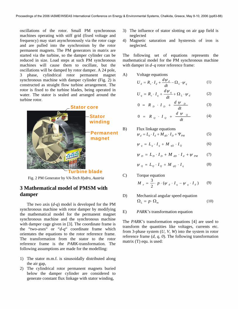
Based on the above mathematical equations, a model for PM synchronous machine with damper cylinder connected to a stiff grid is developed using MATLAB/Simulink. The machine is operated as a generator with input as rated shaft torque applied in the form of water flowing over the turbine and permanent magnet flux linkage ψPM of the magnets embodied in the rotor. Due to high PM flux linkage ψPM and the “weak” damper cylinder, asynchronous starting torque is not sufficient to overcome PM flux linkage braking. So it is not possible to start the machine from grid without any additional accelerating torque (Fig. 3). For simulation the synchronous machine is started with an accelerating torque equal to 75% rated shaft torque. This may be physically realized by water flowing on the blades of hydromatrix turbine. This accelerating shaft torque is applied for first 3 seconds and then rated shaft torque is applied.
- 8 0 0 0
- 6 0 0 0
- 4 0 0 0
- 2 0 0 0
0
2 0 0 0
4 0 0 0
6 0 0 0
8 0 0 0
1 0 0 0 0
0 5 0 1 0 0 1 5 0 2 0 0 2 5 0 3 0 0
R o t o r S p e e d ( r p m )
Torq
ue(N
m)
Fig. 3 Calculated speed vs torque characteristics for induction
machine IM and PMSM
As an alternative, a turbine P controller can be used. The turbine is accelerated by the water flow, with open generator terminals. After reaching the machine synchronous speed the machine is connected to grid. Fig. 4 shows the schematic for such turbine P controller.
ERROR+
-Kp
+-
* s1 1
J
Actualspeed
Ref.speed
activatorswitch (0,1)
electrictorque
Integrator Inertia
Fig. 4 Schematic for the turbine P controller
4 MODEL VERIFICATION
The accuracy of the developed model is verified in two steps by comparing with stationary analytical calculations. A) Machine as an induction machine (ψPM = 0),
considering only rotor damper cylinder.
Following stationary parameters are verified by comparing the simulation result with the analytically calculated values.
Table. 1 Verification as an induction machine Data
verified Analytical
value Simulation
value Diff.
% Static
breakdown torque
8616 Nm 8609 Nm 0.08
No load current
165.18 A 165.1 A 0.05
Slip at load of 5000 Nm
0.14 0.14 0.00
Current at load of
5000 Nm
176.08 A 176.18 A -0.07
IM
PM + IM damper
Proceedings of the 2006 IASME/WSEAS International Conference on Energy & Environmental Systems, Chalkida, Greece, May 8-10, 2006 (pp83-88)

B) As a synchronous machine
Table. 2 Verification as synchronous machine Data
verified Analytical
value Simulation
value Diff. %
Rated current
74.23 A 73.3 A 0.2
Rotor speed
250 rpm 250 rpm 0.00
Torque -11.2 kNm -11.2 kNm 0.00 The simulation results and the analytically calculated values show a good accordance for a single machine. The model is now extended to simulate the parallel operation of 4 permanent magnet synchronous generators. The generators are connected to the stiff grid via a 100 m cable as shown in Fig. 5. (Cable resistance (100 m) RC = 0.0178Ohm; Cable inductance (100 m) LC = 0.0274mH )
Fig. 5 Schematic for parallel operation of grid connected PM synchronous generators.
5 SIMULATION RESULTS AND ANALYSIS
A) Sudden load change on generator M1
Fig. 6 shows the dynamic curve for rotor speed of machine M1. After start up with 75% rated torque, the machine M1 is loaded with twice the rated load at instant t = 10s. Fig. 7 and Fig. 8 show the influence in rotor speed of this sudden load increase on other machines M2, M3 and M4 in parallel and zoomed speed view respectively. It is observed that fluctuation in speed of M1 is maximum and that of the other machines is negligible.
Fig. 6 Calculated speed of machine M1
Fig. 7 Speed of machine M2, M3, M4
Fig. 8 Zoomed view of Fig. 7
B) Blocking of rotor of generator M1 Fig. 9 shows the calculated speed of machine M1, when rotor of machine is blocked for example due to some wood piece strucking to the turbine blades, reducing its speed immediately to zero at instant t =
Proceedings of the 2006 IASME/WSEAS International Conference on Energy & Environmental Systems, Chalkida, Greece, May 8-10, 2006 (pp83-88)

15s. Here the machines are started with turbine P controller. Fig. 10 and 11 show the speed for the other machines M2, M3 and M4 in parallel and the zoomed speed view respectively. Rotor speed for these machines stabilizes to rated speed of 250 rpm after few transients.
Fig. 9 Calculated speed of machine M1
Fig. 10 Speed of machine M2, M3, M4
Fig. 11 Zoomed view for Fig. 8
Fig. 12 shows the torque for machine M1. It is clear that due to blocking, the machine M1 is de-
synchronized and its torque oscillates with very high value around the rated torque of -11.2 kNm. Fig. 13 and Fig. 14 show the corresponding transient torque curves for machines M2, M3 and M4 in parallel. The torque for these machines undergoes the electrical transients of grid frequency just after the blocking with very short time constant, which are superimposed on the long time constant mechanical transients.
Fig. 12 Calculated torque for machine M1
Fig. 13 Torque for machines M2, M3, M4
Fig. 14 Zoomed view of Fig. 13
Proceedings of the 2006 IASME/WSEAS International Conference on Energy & Environmental Systems, Chalkida, Greece, May 8-10, 2006 (pp83-88)

6 CONCLUSIONS
This paper addresses the method of modeling and simulation of parallel operation of PM synchronous generators with damper cylinder being employed as hydro generators. For transient simulations MATLAB/Simulink is used. The parallel operated generators are of rather small power (300kW per unit), being arranged as a so called “hydro matrix” turbine in river barrages. The influence of disturbances in operating conditions like blocking of rotor and sudden load change of one machine, and its effect on the other parallel generators is simulated. The fluctuations caused in speed and torque of these parallel generators due to these disturbances are well within the tolerable limits. Thus parallel operated PM synchronous generators can be considered as a suitable replacement for induction generators in hydromatrix turbine arrangement for future projects. 7 Nomenclature
I [A] electric current L [H] self inductance M [H] mutual inductance M [Nm] torque p [-] number of pole pairs t [s] time U [V] electric voltage ψ [Vs] magnetic flux linkage ΩL [1/s] rotor reference angular frequency Ωm [1/s] mechanical angular speed γ [rad] circumference angle
SUBSCRIPTS
d direct axis quantity D damper winding in direct axis e electric m mechanical q quadrature axis quantity Q damper winding in quadrature axis s stator quantities PM permanent magnet rotor
8 SIMULATION DATA Stator voltage Us 1905 V Rated current Is 52.5 A Synchronous voltage Up 1917 V Frequency f 50 Hz Number of poles 2p = 24 Power factor cosϕ 0.98 Rotor inertia J 397.71 kgm2
Main reactance Xh 7.25 Ohm Synchronous reactance Xs 16.26 Ohm Stator resistance Rs 1.226 Ohm Rotor resistance R’r 2.03 Ohm Rotor reactance X’r 0.49 Ohm Permanent magnet flux ΨPM 8.628 Wb Rated torque MN 11.23 kNm Rated power PN 294 kW 9 REFERENCES [1] Schneeberger, M.; Schmid, H.; StrafloMatrix – further refinement to the HYDROMATRIX technology. VA TECH HYDRO Gmbh & co, Austria, (www.hydromatrix.at). [2] Binder, A.; Schneider, T.; Permanent magnet synchronous generators for regenerative energy conversion – a survey, 11th European Conf. on Power Electronics and Applications (EPE), 11-14.9.2005, Dresden, Germany, CD-Rom, 10 pages, to appear [3] Schröder, D.; Elektrische Antriebe – Grundlagen. 2. ed., Springer, Berlin 2000. [4] Ong, C. M.; Dynamic simulation of electric machinery Prentice Hall PTR, 1998. [5] Pillay, P.; Krishnan, R.; Modelling, simulation and analysis of permanent magnet motor drives, part-I : The permanent magnet synchronous motor drive. IEEE Trans. on Ind. Appl. Vol. 25, No.2, pp. 265-273 March/April, 1989. [6] Xiaoyuan, W.; Na, R.; Simulation of asynchronous starting process of synchronous motors based on MATLAB/Simulink. 6th Int. Conf. on Electrical Machines and Systems-2003, Beijing, pp. 684-687. [7] Cui, X.; Funieru, B.; Binder, A.; PM Generator No-Load Additional Loss Calculation Using FE Models with an Equivalent Current Layer, Proc. Sixth Int. Conf. on Computational Electromagnetics (CEM2006), VDE Verlag, Aachen, Germany, April 4- 6, 2006. [8] Cui, X.; Funieru, B.; Binder, A.: Calculation of No-Load Additional Losses in the Rotor of StrafloMatrix™ Synchronous Turbine-Generators, Int. Symposium on Power Electronics, Electrical Drives, Automation and Motion (SPEEDAM 2006), Taormina, Italy, May 23-26, 2006. (to appear)
Proceedings of the 2006 IASME/WSEAS International Conference on Energy & Environmental Systems, Chalkida, Greece, May 8-10, 2006 (pp83-88)


![On the diameter of random planar graphsfusy/Talks/Aofa2010.pdf(modulo series-parallel operations) 3-connected graphs -> maps •[Whitney]: 3-connected planar graphs 3-connected maps](https://img.pdfslide.net/doc/110x75/5facd3f2b26cc4716248e5e1/on-the-diameter-of-random-planar-fusytalksaofa2010pdf-modulo-series-parallel.jpg)