Embed Size (px)
Citation preview
Modeling and Characterization
of On-Chip Transformers
Sunderarajan S. Mohan, C. Patrick Yue,
Maria del Mar Hershenson,
S. Simon Wong, and Thomas H. Lee
Center for Integrated Systems
Stanford University

OUTLINE
Motivation
Background
On-chip transformer realizations
Models
Experimental verification
Summary
MOTIVATION FOR TRANSFORMER MODELING
Essential for Radio Frequency Integrated Circuits (RFICs)
3-D field solvers are inconvenient
– Numerically expensive and cumbersome
– Good for verification but not for design
Scalable, analytical models
– Design guidelines and explore trade-offs
– Circuit design and optimization

SELF-INDUCTANCE
PSfrag replacements
Quantity Units
A
V
s
H
nH typical in RFOn-chip environ-ment

MUTUAL INDUCTANCE
PSfrag replacements

TRANSFORMERPSfrag replacements
Mutual coupling coefficient,
NON-IDEAL TRANSFORMER
PSfrag replacements
.
Series resistance.
Port-to-port & port-to-substrate capacitances
CONFIGURATIONS
PSfrag replacements
Three or four terminal device
Grounded terminals

TAPPED TRANSFORMER
PSfrag replacements
Inner
spiral
Outer spiral
Low
High ,
Top metal layer
Asymmetric
Low port-to-portcapacitance
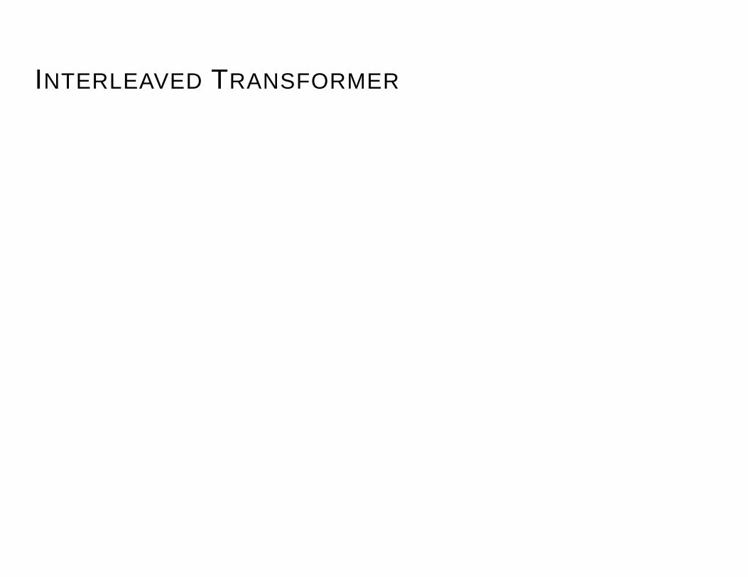
INTERLEAVED TRANSFORMER
PSfrag replacements
Primary Secondary
Medium
Low ,
Top metal layer
Symmetric
Medium port-to-portcapacitance

STACKED TRANSFORMER
PSfrag replacements
Top View
Side Viewtop spiral
bottom spiral
High
High ,
Multiple metal layers
Area efficient
High port-to-port &port-to-substratecapacitances
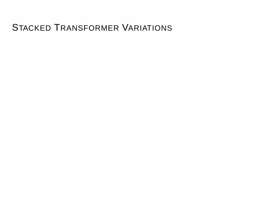
STACKED TRANSFORMER VARIATIONS
PSfrag replacements
Bottom spiral Top spiral
PSfrag replacements
Shift top and bottom spirals laterally or diagonally
Trade-off lower for reduced port-to-port capacitance
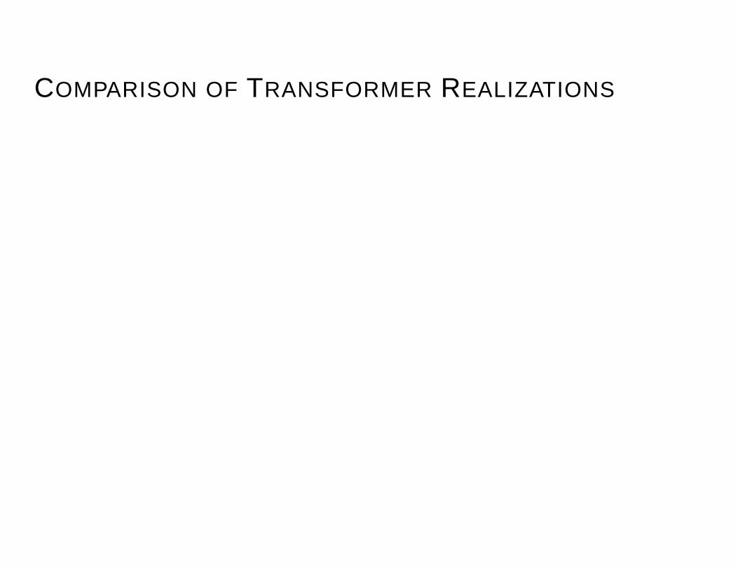
COMPARISON OF TRANSFORMER REALIZATIONS
Transformer Area Coupling Self- Self-resonant
type coefficient, inductance frequency
Tapped High Low Mid High
Interleaved High Mid Low High
Stacked Low High High Low
Non-idealities result in trade-offs
Optimal choice determined by circuit application
Transformer models needed for comparison

SELF-INDUCTANCE CALCULATIONPSfrag replacements
Absolute error
Indu
ctor
sex
ceed
ing
abs.
erro
r
modified Wheeler expression
PSfrag replacements
Verified by measurements (75) and 3-D field solver simulations (17,000)
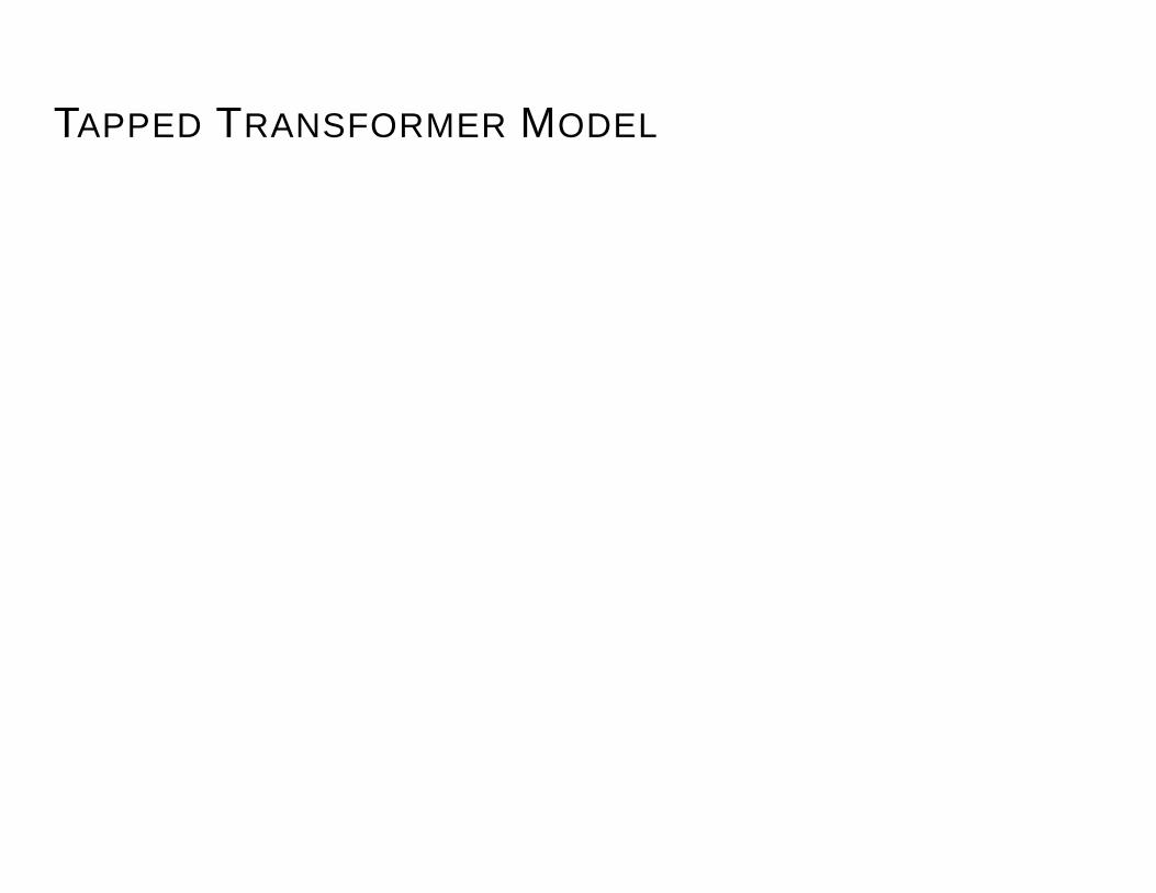
TAPPED TRANSFORMER MODEL
PSfrag replacements
Port1
Port2
PSfrag replacements(inner)
(outer)
Evaluate , , ,& by extending
previous work
Use modified Wheelerexpression for ,
Calculate
MUTUAL INDUCTANCE CALCULATION
Single inductor.
PSfrag replacements
Interleaved transformer.
PSfrag replacements
(primary) (secondary)
Tapped transformer.
PSfrag replacements (inner)
(outer)

FOR TAPPED AND INTERLEAVED TRANSFORMERS
1. Find , and
2. Determine from
3. Evaluate
STACKED TRANSFORMER MODEL
PSfrag replacements
Port1
Port2
PSfrag replacements
Evaluate , , ,, & by extending
previous work
Use modified Wheelerexpression for ,
Calculate

CURRENT SHEET APPROACH FOR
PSfrag replacements
Reduce complexity by
Use symmetry
Derive simple expression using electromagnetic theory

FOR STACKED TRANSFORMERSPSfrag replacements
predicted kmeasured k
Mut
ualC
oupl
ing
Coe
ffici
ent(
)
(for )PSfrag replacements
Metal and oxide thicknesses have only 2nd order effects on

FOR STACKED TRANSFORMERS
1. Find and
2. Determine
3. Evaluate

ACCURACY OF MODELS
Lumped model of distributed structure
Substrate not modeled
Patterned Ground Shield (PGS)
– Eliminates resistive and capacitive coupling to substrate
– Inductive coupling to substrate may degrade performanceat high frequencies
EXPERIMENTAL SET-UP
PSfrag replacements
S parameters
DUT
Coplanar GSG probes
HP8720Bnetwork analyzer
environment
port 1 port 2
port 3
PSfrag replacementsport 1
port 1
port 2
port 2
port 3
port 3

DIE PHOTO

EXPERIMENTAL VERIFICATION: TAPPED
,
,
,
0.8 1.2 1.6 2.0 2.4Frequency (GHz)
-1.0
-0.5
0.0
0.5
1.0
S 21
real(S21) measimag(S21) measreal(S21) calcimag(S21) calc
PSfrag replacements
Frequency(GHz)
0.8 1.2 1.6 2.0 2.4Frequency (GHz)
-1.0
-0.5
0.0
0.5
1.0
S 11
real(S11) measimag(S11) measreal(S11) calcimag(S11) calc
PSfrag replacements
Frequency(GHz)
0.8 1.2 1.6 2.0 2.4Frequency (GHz)
-1.0
-0.5
0.0
0.5
1.0
S 22 real(S22) measimag(S22) measreal(S22) calcimag(S22) calc
PSfrag replacements
Frequency(GHz)
Frequency(GHz)
EXPERIMENTAL VERIFICATION: STACKED 1Stacked transformer withtop spiral overlapping bot-tom one
, ,,
, ,
0.0 0.5 1.0 1.5Frequency (GHz)
-1.0
-0.5
0.0
0.5
1.0
S 21
real(S21) measimag(S21) measreal(S21) calcimag(S21) calc
PSfrag replacements
Frequency(GHz)
0.0 0.5 1.0 1.5Frequency (GHz)
-1.0
-0.5
0.0
0.5
1.0
S 11
real(S11) measimag(S11) measreal(S11) calcimag(S11) calc
PSfrag replacements
Frequency(GHz)
0.0 0.5 1.0 1.5Frequency (GHz)
-1.0
-0.5
0.0
0.5
1.0
S 22
real(S22) measimag(S22) measreal(S22) calcimag(S22) calc
PSfrag replacements
Frequency(GHz)
Frequency(GHz)

CONTRIBUTIONS
On-chip transformer models
Expressions for mutual inductance andmutual coupling coefficient
Models verified by measurements
Basis for design and optimization oftransformer circuits

ACKNOWLEDGMENTS
IBM fellowship support
NSF contract MIP-9313701
Rockwell InternationalDr. Christopher HullDr. Paramjit Singh
Staff of the Stanford Nanofabrication Facility
Industrial Sponsors of the Center for Integrated Systems