Embed Size (px)
Citation preview
THE ANNALS “DUNĂREA DE JOS” OF GALAŢI FASCICLE V, TECHOLOLOGIES IN MECANICAL ENGINEERING,
ISSN 1221-4566, 2011
95
MODELLING AND SIMULATION OF THE MANUFACTURING OF A TWISTED DRILL WITH THREE CURVED CUTTING EDGES, USING
THE SV& TOOLBOX SOFTWARE
Eng. Baroiu Nicusor1, Eng. Berbinschi Silviu1, PhD. Eng. Teodor Virgil1, Stud. Urse Cătălin1
1 “Dunărea de Jos” University of Galaţi, Romania [email protected]
ABSTRACT
The paper presents dedicated software – SV& Toolbox - developed with the purpose of designing, simulating and manufacturing a twisted drill with three curved egdes. With this purpose a few basic features are presented, concerning the development of the processing technology on machines with numerical control through the computer. KEYWORDS: multi-flute drill, modelling, simulation, manufacturing, CNC, SV& Toolbox
1. Introduction
Helical drills with three curved cutting edges are cutting tools with a complex geometry, as far as both the helical flute for chip disposal – geometry determined by de requirements to have a an efficient disposal of the cuts along the exterior part of the tool- and the geometry of the cutting edge. The surface development, which creates these geometries, is based on the fundamental coiling theory [5], after which various methods were developed, from analytical [7], complementary analytical, to grapho-analytical and graphical [1], [2].
In this paper, a method of geometry design is covered, for a twisted drill with three curved edges on a machine tool with numerical control assisted by a computer, based on the complex surface development with the help of other surfaces, conjugated by coiling through the SV& Toolbox [3], [4], [6] software pack.
In this case, the most simple geometrical shapes are employed (cylindrical – the basic shape of the semi-finished from which the drill will be made, taper – the basic shape of the grinding disk that generates the twisted flutes etc.), but which are subjected to some complicated displacements regulated after 5 or even 6 axes of variance, simultaneously interpolated.
The result is similar to that in which tool shaping is done by coiling, by using elements of matrix algebra, but with an extremely high flexibility, while the software product is able to generate codes for CNC machines.
2. The SV & Toolbox software pack – general description
The SV& Toolbox software (made by Tools Wizard GmbH Switzerland, member of System V&, Romania group), is an application optimized for any type of machine with numerical controls with minimum 5 axes, which is a processing system for electronic data (EDP), used to engineer and sharpen cutting tools. The applications are mathematically based to generate the cutting tools surfaces that rotate around their own axis together with the feed motion. The SV& Toolbox applications give a solution to the issue of producing and resharpening some cutting tools of the following type: classic end-mill cutters, profiling end-mill cutters-gear-tooth or disc type, conical cutters, standard twist drill, stepped drills, drill for deep boring, tap borers, various profiling blades etc. The applications have a modular character and can be personalized for any type of kinematics or of CNC of the tool machine, all reprocessing being made with standardized or specialized abrasive disks.
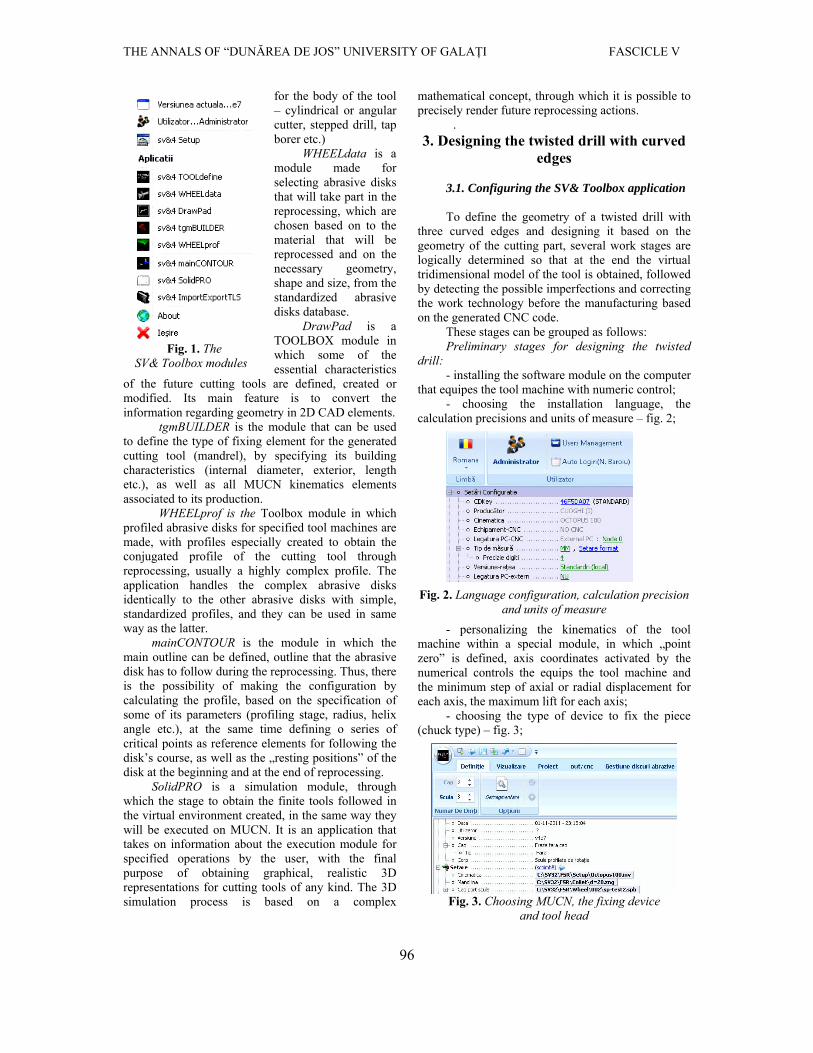
The defining modules of the application are: TOOLdefine, WHEELdata, DrawPad, tgmBUILDER, WHEELprof, mainCONTOUR, SolidPRO – figure 1.
TOOLDefine is the module in which one can create configurations of new cutting tools or the predefined ones can be used, already existent in the data base of the application, for both the active, head of the tool – the module contains in the standard version geometries for twisted drills and cutters, and
THE ANNALS OF “DUNĂREA DE JOS” UNIVERSITY OF GALAŢI FASCICLE V
96
for the body of the tool – cylindrical or angular cutter, stepped drill, tap borer etc.)
WHEELdata is a module made for selecting abrasive disks that will take part in the reprocessing, which are chosen based on to the material that will be reprocessed and on the necessary geometry, shape and size, from the standardized abrasive disks database.
DrawPad is a TOOLBOX module in which some of the essential characteristics
of the future cutting tools are defined, created or modified. Its main feature is to convert the information regarding geometry in 2D CAD elements.
tgmBUILDER is the module that can be used to define the type of fixing element for the generated cutting tool (mandrel), by specifying its building characteristics (internal diameter, exterior, length etc.), as well as all MUCN kinematics elements associated to its production.
WHEELprof is the Toolbox module in which profiled abrasive disks for specified tool machines are made, with profiles especially created to obtain the conjugated profile of the cutting tool through reprocessing, usually a highly complex profile. The application handles the complex abrasive disks identically to the other abrasive disks with simple, standardized profiles, and they can be used in same way as the latter.
mainCONTOUR is the module in which the main outline can be defined, outline that the abrasive disk has to follow during the reprocessing. Thus, there is the possibility of making the configuration by calculating the profile, based on the specification of some of its parameters (profiling stage, radius, helix angle etc.), at the same time defining o series of critical points as reference elements for following the disk’s course, as well as the „resting positions” of the disk at the beginning and at the end of reprocessing.
SolidPRO is a simulation module, through which the stage to obtain the finite tools followed in the virtual environment created, in the same way they will be executed on MUCN. It is an application that takes on information about the execution module for specified operations by the user, with the final purpose of obtaining graphical, realistic 3D representations for cutting tools of any kind. The 3D simulation process is based on a complex
mathematical concept, through which it is possible to precisely render future reprocessing actions.
. 3. Designing the twisted drill with curved
edges
3.1. Configuring the SV& Toolbox application
To define the geometry of a twisted drill with three curved edges and designing it based on the geometry of the cutting part, several work stages are logically determined so that at the end the virtual tridimensional model of the tool is obtained, followed by detecting the possible imperfections and correcting the work technology before the manufacturing based on the generated CNC code.
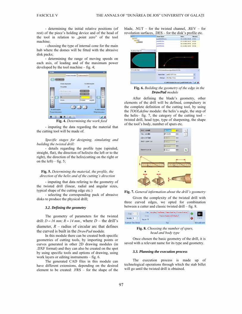
These stages can be grouped as follows: Preliminary stages for designing the twisted
drill: - installing the software module on the computer
that equipes the tool machine with numeric control; - choosing the installation language, the
calculation precisions and units of measure – fig. 2;
Fig. 2. Language configuration, calculation precision and units of measure
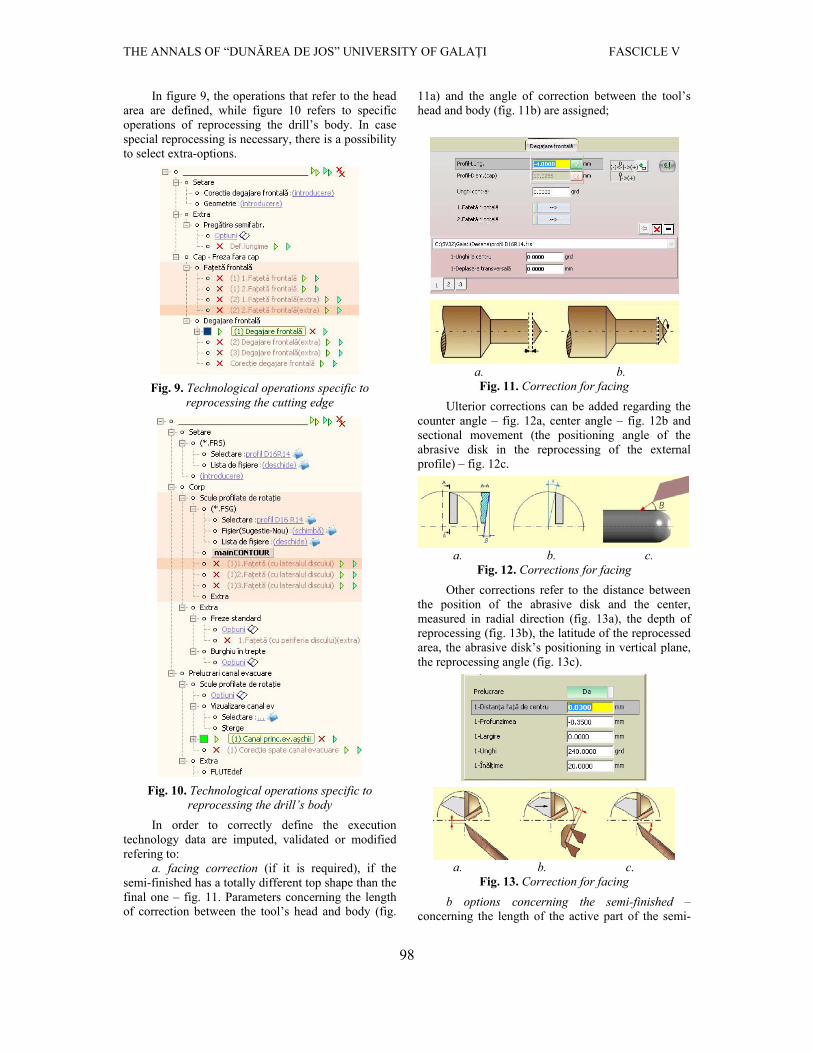
- personalizing the kinematics of the tool machine within a special module, in which „point zero” is defined, axis coordinates activated by the numerical controls the equips the tool machine and the minimum step of axial or radial displacement for each axis, the maximum lift for each axis;
- choosing the type of device to fix the piece (chuck type) – fig. 3;
Fig. 3. Choosing MUCN, the fixing device and tool head
Fig. 1. The
SV& Toolbox modules
FASCICLE V THE ANNALS OF “DUNĂREA DE JOS” UNIVERSITY OF GALAŢI
97
- determining the initial relative positions (of rest) of the piece’s holding device and of the head of the tool in relation to „point zero” of the tool machine;
- choosing the type of internal cone for the main hub where the domes will be fitted with the abrasive disk packs;
- determining the range of moving speeds on each axis, of leading and of the maximum power developed by the tool machine – fig. 4;
Fig. 4. Determining the work feed
- imputing the data regarding the material that the cutting tool will be made of.
Specific stages for designing, simulating and
building the twisted drill: - details regarding the profile type (spiraled,
straight, flat), the direction of helix(to the left or to the right), the direction of the helix(cutting on the right or on the left) – fig. 5;
Fig. 5. Determining the material, the profile, the direction of the helix and of the cutting’s direction
- imputing that data refering to the geometry of the twisted drill (linear, radial and angular sizes, typical shape of the cutting edge etc.)
- selecting the corresponding pack of abrasive disks to produce the physical drill;
3.2. Defining the geometry
The geometry of parameters for the twisted
drill: D 16 mm; R 14 mm , where D – the drill’s diameter, R – radius of circular arc that defines the curved is built in the DrawPad module.
In this module there can be created both specific geometries of cutting tools, by importing points or curves generated in other 2D drawing modules (in .DXF format) and they can also be created on the spot by using specific tools and options of drawing, using work layers or editing instruments – fig. 6.
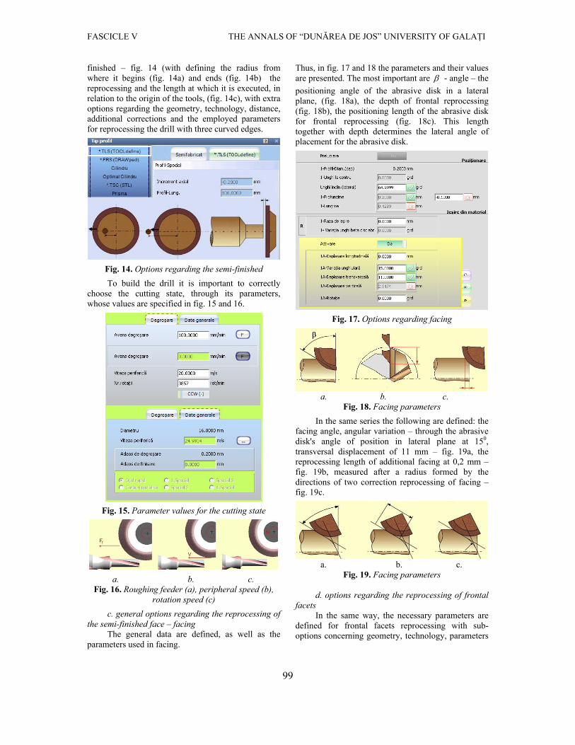
The generated CAD files in this module can have different extensions, depending on the desired element to be created: .FRS – for the shape of the
blade, .NUT – for the twisted channel, .REV – for revolution surfaces, .DES – for the disk’s profile etc.
Fig. 6. Building the geometry of the edge in the DrawPad module
After defining the blade’s geometry, other elements of the drill will be defined, compulsory in the complete definition of the cutting tool, by using the TOOLdefine module: the helix’s angle, the step of the helix– fig. 7, the category of the cutting tool – twisted drill, head type, type of sharpening, the shape of the tool’s body, number of spurs etc.
Fig. 7. General information about the drill’s geometry
Given the complexity of the twisted drill with three curved edges, we opted for combination between a cutter and classic twisted drill – fig. 8.
Fig. 8. Choosing the number of spurs, head and body type
Once chosen the basic geometry of the drill, it is saved with a relevant name for its type and geometry.
3.3. Planning the execution process
The execution process is made up of
technological operations through which the stab billet will go until the twisted drill is obtained.
THE ANNALS OF “DUNĂREA DE JOS” UNIVERSITY OF GALAŢI FASCICLE V
98
In figure 9, the operations that refer to the head area are defined, while figure 10 refers to specific operations of reprocessing the drill’s body. In case special reprocessing is necessary, there is a possibility to select extra-options.
Fig. 9. Technological operations specific to reprocessing the cutting edge
Fig. 10. Technological operations specific to reprocessing the drill’s body
In order to correctly define the execution technology data are imputed, validated or modified refering to:
a. facing correction (if it is required), if the semi-finished has a totally different top shape than the final one – fig. 11. Parameters concerning the length of correction between the tool’s head and body (fig.
11a) and the angle of correction between the tool’s head and body (fig. 11b) are assigned;
a. b. Fig. 11. Correction for facing
Ulterior corrections can be added regarding the counter angle – fig. 12a, center angle – fig. 12b and sectional movement (the positioning angle of the abrasive disk in the reprocessing of the external profile) – fig. 12c.
a. b. c.
Fig. 12. Corrections for facing
Other corrections refer to the distance between the position of the abrasive disk and the center, measured in radial direction (fig. 13a), the depth of reprocessing (fig. 13b), the latitude of the reprocessed area, the abrasive disk’s positioning in vertical plane, the reprocessing angle (fig. 13c).
a. b. c. Fig. 13. Correction for facing
b options concerning the semi-finished – concerning the length of the active part of the semi-
FASCICLE V THE ANNALS OF “DUNĂREA DE JOS” UNIVERSITY OF GALAŢI
99
finished – fig. 14 (with defining the radius from where it begins (fig. 14a) and ends (fig. 14b) the reprocessing and the length at which it is executed, in relation to the origin of the tools, (fig. 14c), with extra options regarding the geometry, technology, distance, additional corrections and the employed parameters for reprocessing the drill with three curved edges.
Fig. 14. Options regarding the semi-finished
To build the drill it is important to correctly choose the cutting state, through its parameters, whose values are specified in fig. 15 and 16.
Fig. 15. Parameter values for the cutting state
a. b. c. Fig. 16. Roughing feeder (a), peripheral speed (b),
rotation speed (c)
c. general options regarding the reprocessing of the semi-finished face – facing
The general data are defined, as well as the parameters used in facing.
Thus, in fig. 17 and 18 the parameters and their values are presented. The most important are - angle – the
positioning angle of the abrasive disk in a lateral plane, (fig. 18a), the depth of frontal reprocessing (fig. 18b), the positioning length of the abrasive disk for frontal reprocessing (fig. 18c). This length together with depth determines the lateral angle of placement for the abrasive disk.
Fig. 17. Options regarding facing
a. b. c.
Fig. 18. Facing parameters
In the same series the following are defined: the facing angle, angular variation – through the abrasive disk's angle of position in lateral plane at 150, transversal displacement of 11 mm – fig. 19a, the reprocessing length of additional facing at 0,2 mm – fig. 19b, measured after a radius formed by the directions of two correction reprocessing of facing – fig. 19c.
a. b. c.
Fig. 19. Facing parameters
d. options regarding the reprocessing of frontal facets
In the same way, the necessary parameters are defined for frontal facets reprocessing with sub-options concerning geometry, technology, parameters
THE ANNALS OF “DUNĂREA DE JOS” UNIVERSITY OF GALAŢI FASCICLE V
100
of cutting state and the needed corrections for this reprocessing.
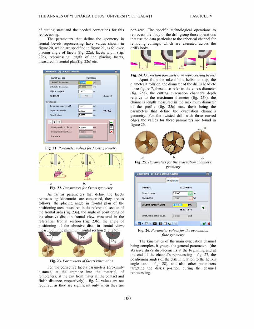
The parameters that define the geometry in frontal bevels reprocessing have values shown in figure 20, which are specified in figure 21, as follows: placing angle of facets (fig. 22a), facets width (fig. 22b), reprocessing length of the placing facets, measured in frontal plan(fig. 22c) etc.
Fig. 21. Parameter values for facets geometry
a. b. c. Fig. 22. Parameters for facets geometry
As far as parameters that define the facets reprocessing kinematics are concerned, they are as follows: the placing angle in frontal plan of the positioning area, measured in the referential section of the frontal area (fig. 23a), the angle of positioning of the abrasive disk, in frontal view, measured in the referential frontal section (fig. 23b), the angle of positioning of the abrasive disk, in frontal view, measured in the minimum frontal section (fig. 23c).
Fig. 23. Parameters of facets kinematics
For the corrective facets parameters (proximity distance, at the entrance into the material, of remoteness, at the exit from material, the contact and finish distance, respectively) - fig. 24 values are not required, as they are significant only when they are
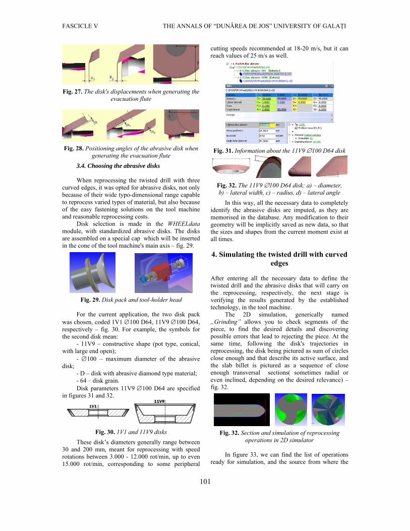
non-zero. The specific technological operations to reprocess the body of the drill group those operations that use the data particular to the spherical channel for removing cuttings, which are executed across the drill's body.
Fig. 24. Correction parameters in reprocessing bevels Apart from the rake of the helix, its step, the
diameter it rolls on, the diameter of the drill's head etc – see figure 7, these also refer to the core's diameter (fig. 25a), the cutting evacuation channel's depth relative to the maximum diameter (fig. 25b), the channel's length measured in the maximum diameter of the profile (fig. 25c) etc., these being the parameters that define the evacuation channel's geometry. For the twisted drill with three curved edges the values for these parameters are found in figure 26.
a. b. c.
Fig. 25. Parameters for the evacuation channel's geometry
Fig. 26. Parameter values for the evacuation flute geometry
The kinematics of the main evacuation channel being complex, it groups the general parameters (the abrasive disk's displacements at the beginning and at the end of the channel's reprocessing - fig. 27, the positioning angles of the disk in relation to the helix's angle etc. – fig. 28), and also other parameters targeting the disk's position during the channel reprocessing.
FASCICLE V THE ANNALS OF “DUNĂREA DE JOS” UNIVERSITY OF GALAŢI
101
Fig. 27. The disk's displacements when generating the evacuation flute
Fig. 28. Positioning angles of the abrasive disk when generating the evacuation flute
3.4. Choosing the abrasive disks
When reprocessing the twisted drill with three curved edges, it was opted for abrasive disks, not only because of their wide typo-dimensional range capable to reprocess varied types of material, but also because of the easy fastening solutions on the tool machine and reasonable reprocessing costs.
Disk selection is made in the WHEELdata module, with standardized abrasive disks. The disks are assembled on a special cap which will be inserted in the cone of the tool machine's main axis – fig. 29.
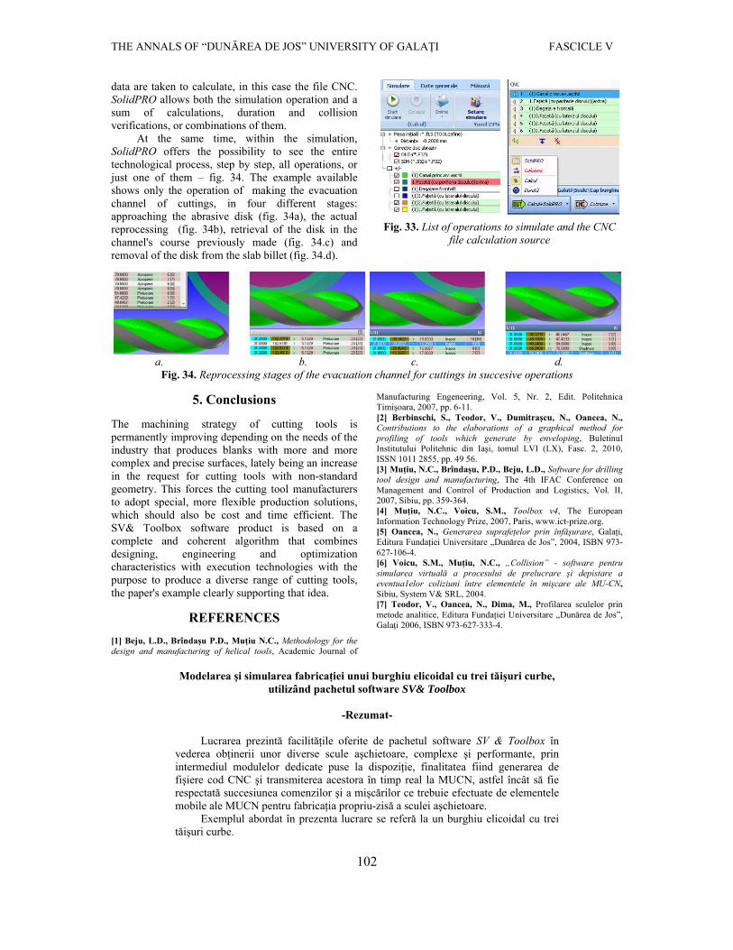
Fig. 29. Disk pack and tool-holder head For the current application, the two disk pack
was chosen, coded 1V1 100 D64, 11V9 100 D64, respectively – fig. 30. For example, the symbols for the second disk mean:
- 11V9 – constructive shape (pot type, conical, with large end open);
- 100 – maximum diameter of the abrasive disk;
- D – disk with abrasive diamond type material; - 64 – disk grain. Disk parameters 11V9 100 D64 are specified
in figures 31 and 32.
Fig. 30. 1V1 and 11V9 disks
These disk’s diameters generally range between 30 and 200 mm, meant for reprocessing with speed rotations between 3.000 - 12.000 rot/min, up to even 15.000 rot/min, corresponding to some peripheral
cutting speeds recommended at 18-20 m/s, but it can reach values of 25 m/s as well.
Fig. 31. Information about the 11V9 100 D64 disk
Fig. 32. The 11V9 100 D64 disk: a) – diameter, b) – lateral width, c) – radius, d) – lateral angle
In this way, all the necessary data to completely identify the abrasive disks are imputed, as they are memorised in the database. Any modification to their geometry will be implicitly saved as new data, so that the sizes and shapes from the current moment exist at all times. 4. Simulating the twisted drill with curved
edges
After entering all the necessary data to define the twisted drill and the abrasive disks that will carry on the reprocessing, respectively, the next stage is verifying the results generated by the established technology, in the tool machine.
The 2D simulation, generically named „Grinding” allows you to check segments of the piece, to find the desired details and discovering possible errors that lead to rejecting the piece. At the same time, following the disk's trajectories in reprocessing, the disk being pictured as sum of circles close enough and that describe its active surface, and the slab billet is pictured as a sequence of close enough transversal sections( sometimes radial or even inclined, depending on the desired relevance) – fig. 32.
Fig. 32. Section and simulation of reprocessing operations in 2D simulator
In figure 33, we can find the list of operations
ready for simulation, and the source from where the
THE ANNALS OF “DUNĂREA DE JOS” UNIVERSITY OF GALAŢI FASCICLE V
102
data are taken to calculate, in this case the file CNC. SolidPRO allows both the simulation operation and a sum of calculations, duration and collision verifications, or combinations of them.
At the same time, within the simulation, SolidPRO offers the possibility to see the entire technological process, step by step, all operations, or just one of them – fig. 34. The example available shows only the operation of making the evacuation channel of cuttings, in four different stages: approaching the abrasive disk (fig. 34a), the actual reprocessing (fig. 34b), retrieval of the disk in the channel's course previously made (fig. 34.c) and removal of the disk from the slab billet (fig. 34.d).
Fig. 33. List of operations to simulate and the CNC file calculation source
a. b. c. d.
Fig. 34. Reprocessing stages of the evacuation channel for cuttings in succesive operations
5. Conclusions The machining strategy of cutting tools is permanently improving depending on the needs of the industry that produces blanks with more and more complex and precise surfaces, lately being an increase in the request for cutting tools with non-standard geometry. This forces the cutting tool manufacturers to adopt special, more flexible production solutions, which should also be cost and time efficient. The SV& Toolbox software product is based on a complete and coherent algorithm that combines designing, engineering and optimization characteristics with execution technologies with the purpose to produce a diverse range of cutting tools, the paper's example clearly supporting that idea.
REFERENCES [1] Beju, L.D., Brîndaşu P.D., Muţiu N.C., Methodology for the design and manufacturing of helical tools, Academic Journal of
Manufacturing Engeneering, Vol. 5, Nr. 2, Edit. Politehnica Timişoara, 2007, pp. 6-11. [2] Berbinschi, S., Teodor, V., Dumitraşcu, N., Oancea, N., Contributions to the elaborations of a graphical method for profiling of tools which generate by enveloping, Buletinul Institutului Politehnic din Iaşi, tomul LVI (LX), Fasc. 2, 2010, ISSN 1011 2855, pp. 49 56. [3] Muţiu, N.C., Brîndaşu, P.D., Beju, L.D., Software for drilling tool design and manufacturing, The 4th IFAC Conference on Management and Control of Production and Logistics, Vol. II, 2007, Sibiu, pp. 359-364. [4] Muţiu, N.C., Voicu, S.M., Toolbox v4, The European Information Technology Prize, 2007, Paris, www.ict-prize.org. [5] Oancea, N., Generarea suprafeţelor prin înfăşurare, Galaţi, Editura Fundaţiei Universitare „Dunărea de Jos”, 2004, ISBN 973-627-106-4. [6] Voicu, S.M., Muţiu, N.C., „Collision” - software pentru simularea virtuală a procesului de prelucrare şi depistare a eventua1elor coliziuni între elementele în mişcare ale MU-CN, Sibiu, System V& SRL, 2004. [7] Teodor, V., Oancea, N., Dima, M., Profilarea sculelor prin metode analitice, Editura Fundaţiei Universitare „Dunărea de Jos”, Galaţi 2006, ISBN 973-627-333-4.
Modelarea şi simularea fabricaţiei unui burghiu elicoidal cu trei tăişuri curbe,
utilizând pachetul software SV& Toolbox
-Rezumat-
Lucrarea prezintă facilităţile oferite de pachetul software SV & Toolbox în vederea obţinerii unor diverse scule aşchietoare, complexe şi performante, prin intermediul modulelor dedicate puse la dispoziţie, finalitatea fiind generarea de fişiere cod CNC şi transmiterea acestora în timp real la MUCN, astfel încât să fie respectată succesiunea comenzilor şi a mişcărilor ce trebuie efectuate de elementele mobile ale MUCN pentru fabricaţia propriu-zisă a sculei aşchietoare.
Exemplul abordat în prezenta lucrare se referă la un burghiu elicoidal cu trei tăişuri curbe.