Embed Size (px)
Citation preview

Modelling of Emission and Modelling of Emission and Blocking maskBlocking mask
European Communications OfficeJean-Philippe Kermoal (ECO)
October 2010
EUROPEANCOMMUNICATIONSOFFICE
Nansensgade 19DK-1366 CopenhagenDenmark
Telephone: + 45 33 89 63 00Telefax: + 45 33 89 63 30
E-mail: [email protected] Site: http://www.ero.dk

SEAMCAT WorkshopJean-Philippe Kermoal / ECO
Page 2 05 October 2010
OutlineOutline
• Input to SEAMCAT• General• CDMA Unwanted emission mask
– BS example– UE example
• ACLR• Blocking mask• ACS• Emission floor

SEAMCAT WorkshopJean-Philippe Kermoal / ECO
Page 3 05 October 2010
Input to SEAMCATInput to SEAMCAT
• The emission mask defaults value • Remove the default using the Clear button.• Then use the add button to add the enough blank rows for
half of the emission mask.• Note the format of the data:
– Offset = MHz– Unwanted = dBc– Reference bandwidth = kHz

SEAMCAT WorkshopJean-Philippe Kermoal / ECO
Page 4 05 October 2010
Input to SEAMCATInput to SEAMCAT
• Then use the Sym button to get a symetric mask

SEAMCAT WorkshopJean-Philippe Kermoal / ECO
Page 5 05 October 2010
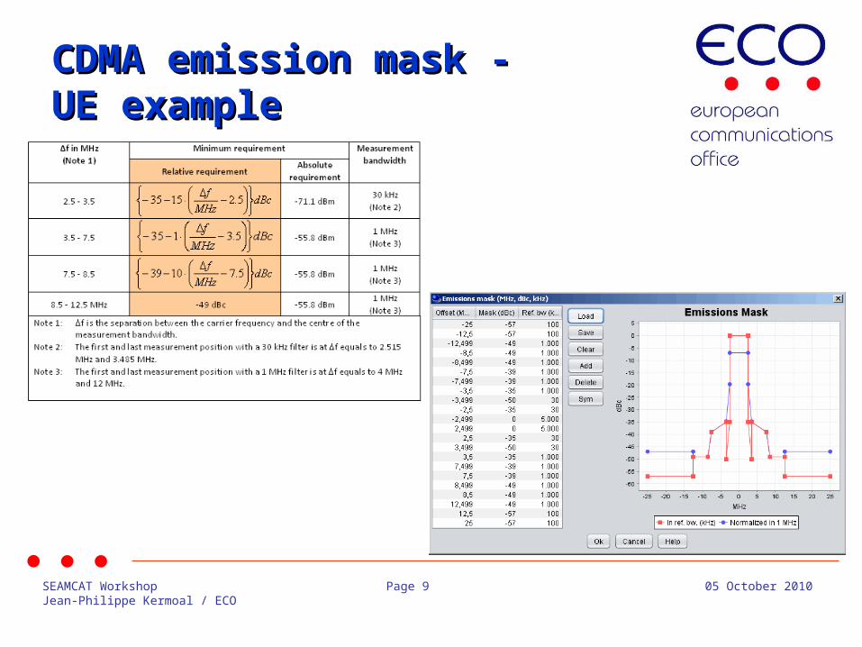
Reference/normalised Reference/normalised bandwidthbandwidth• Once SEAMCAT has generated the whole mask,
first check that the values are in the correct order.
• The unwanted emission diagram shows two masks
The red mask is the representation using the user defined reference bandwidth.
The blue mask is normalised to 1MHz measurement bandwidth. The user may normalise his input to 1MHz bandwidth but it can be useful to input the mask in the bandwidth defined in the standard and allow SEAMCAT to create normalised mask.

SEAMCAT WorkshopJean-Philippe Kermoal / ECO
Page 6 05 October 2010
Store your maskStore your mask• Spectrum mask can be saved as .txt file • it can be reused for other workspaces using
load buttons.

SEAMCAT WorkshopJean-Philippe Kermoal / ECO
Page 7 05 October 2010
GeneralGeneral
• The following range of attenuation is considered, for a system of 30dBm using a 20kHz emission bandwidth.
• The reference bandwidth for the attenuation is 10kHz.
• Within the emission bandwidth the reference bandwidth is taken equal to the emission bandwidth.
• Note: The technical specifications of the receiver and transmitter are commonly extracted from the ETSI standard (see http://www.etsi.org/WebSite/Standards/Standard.aspx)

SEAMCAT WorkshopJean-Philippe Kermoal / ECO
Page 8 05 October 2010
CDMA emission mask -CDMA emission mask -BS exampleBS example
• Assuming a BS Tx power of 43 dBm, and with addition of the ITU-R SM.329 limit above 12.5 MHz
Spectrum emission mask values, BS maximum output power P 43 dBm (TS25.104)
SEAMCAT WorkshopJean-Philippe Kermoal / ECO
Page 9 05 October 2010
CDMA emission mask -CDMA emission mask -UE exampleUE example

SEAMCAT WorkshopJean-Philippe Kermoal / ECO
Page 10 05 October 2010
ACIR = f(ACLR, ACS)ACIR = f(ACLR, ACS)
• ACIR = adjacent-channel interference ratio
• In UL, the dominant part of ACIR is due to the UE adjacent channel leakage (ACLR) i.e. ACSBS is very large compare to ACLRUE and ACIR ≈ ACLRUE.
• In DL, the dominant part of ACIR is due to the UE frequency selectivity (ACS) i.e. ACLRBS is very large compare to ACSUE and ACIR ≈ ACSUE
ACSACLR
ACIR11
1
SEAMCAT WorkshopJean-Philippe Kermoal / ECO
Page 11 05 October 2010
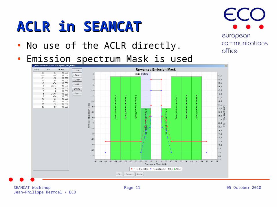
ACLR in SEAMCATACLR in SEAMCAT• No use of the ACLR directly. • Emission spectrum Mask is used

SEAMCAT WorkshopJean-Philippe Kermoal / ECO
Page 12 05 October 2010
Blocking MaskBlocking Mask
• User-defined mode
• Protection ratio• Sensitivity modes
fv
Receiver Mask
fI
Rx bandwidth
Rejection of the receiver
ACS(ETSI)
Blocking (ETSI)
+
Blocking:
Blocking Response =(PR and Sensitivity mode)
fv
Receiver Mask
fI
Rx bandwidth
Rejection of the receiver
Blocking Response = filtering (user defined mode)
Blocking:

SEAMCAT WorkshopJean-Philippe Kermoal / ECO
Page 13 05 October 2010
BS blocking MaskBS blocking Mask

SEAMCAT WorkshopJean-Philippe Kermoal / ECO
Page 14 05 October 2010
ACS in SEAMCATACS in SEAMCAT
• ACS is the same as the blocking attenuation input

SEAMCAT WorkshopJean-Philippe Kermoal / ECO
Page 15 05 October 2010
Emission FloorEmission Floor
• This emission floor mask (frequency offset (MHz), emission floor (dBm), reference bandwidth (MHz)).
• Useful when power control is used

SEAMCAT WorkshopJean-Philippe Kermoal / ECO
Page 16 05 October 2010
Thank you - Any Questions?Thank you - Any Questions?