Embed Size (px)
Citation preview
Annals of Nuclear Energy 61 (2013) 135–142
Contents lists available at SciVerse ScienceDirect
Annals of Nuclear Energy
journal homepage: www.elsevier .com/locate /anucene
Modelling of fission-product transport in the reactor coolant system
0306-4549/$ - see front matter � 2013 Elsevier Ltd. All rights reserved.http://dx.doi.org/10.1016/j.anucene.2013.02.035
Abbreviations: FP, fission product; ISTP, international source term programme;CHIP, chemistry of iodine in the primary; RCS, reactor coolant system; LWR, light–water reactor; AECL, Atomic Energy of Canada Ltd.; CANDU, CANada DeuteriumUranium; SG, steam generator; AMMD, aerodynamic mass-median diameter; GSD,geometric standard deviation..⇑ Corresponding author. Tel.: +33 4 42 19 94 79; fax: +33 4 42 19 91 67.
E-mail address: [email protected] (F. Cousin).
F. Cousin ⇑, M.P. Kissane, N. GiraultInstitut de Radioprotection et de Sûreté Nucléaire, PSN-RES/SAG, BP3, 13115 St. Paul Lez Durance, France
a r t i c l e i n f o a b s t r a c t
Article history:Received 18 October 2012Accepted 13 February 2013Available online 23 April 2013
Keywords:Fission productAerosolTransportSevere accidentModelling
The Phébus fission product (FP) programme studies the phenomenology of severe accidents in water-cooled nuclear reactors. Five tests were performed in the frame of the programme covering fuel-rod deg-radation and FP behaviour released via the coolant system into the containment. To model FP transportand behaviour in the coolant system, numerous physical and chemical phenomena have to be taken intoaccount. In the vapour phase, for example, FP speciation, vapour condensation and vapour/surface orvapour/aerosol reactions have to be considered. The aerosol phase has to be modelled with nucleation,growth and deposition processes. Finally, remobilisation phenomena like resuspension and revaporisa-tion have to be taken into account for delayed release into the containment. Four Phébus FP tests(FTP0, FPT1, FPT2, FPT3) have been modelled with the ASTEC/SOPHAEROS code. Modelling shows anoverall good estimation of retention for the main FPs (e.g., I, Cs, Mo). Furthermore, a strong connectionis revealed in the gaseous phase chemistry between I, Cs, Cd and Mo which has a great impact on gaseousiodine release into the containment. The Phébus FP test modelling also exposes disagreement on FPretention when laminar gaseous flow is not well developed. Finally, probably the most significant short-coming in modelling that Phébus-FP tests highlighted concerns vapour-phase iodine-chemistry model-ling at low temperature. The study of this latter point is on going with the experimental programmeISTP/CHIP.
� 2013 Elsevier Ltd. All rights reserved.
1. Introduction
The release of radioactive products outside a nuclear plant (con-stituting the source term) undergoing a severe accident dependson many different coupled phenomena. To evaluate isotopic inven-tory, chemical speciation and physical form of fission products(FPs) and other radionuclides outside the containment, severalsteps have to be followed. Firstly, FP release from fuel requiresevaluation where this will be influenced by temperature, core deg-radation and atmosphere conditions (Grégoire and Haste, thisissue; Brillant et al., this issue). Secondly, FP transport throughthe Reactor Coolant System (RCS) can affect FP speciation andthe physical form as well as the quantity of FPs released to thecontainment. Thirdly, FP behaviour in the containment has to betaken into account, especially that of iodine due to its volatileforms (transfers between liquid and gas phases, heterogeneouschemistry, etc.), Simondi-Teisseire et al. (this issue), Glowa et al.
(this issue). While the concern here specifically relates to light–water reactors (LWRs), some of what is described can apply toother technologies such as gas-cooled reactors.
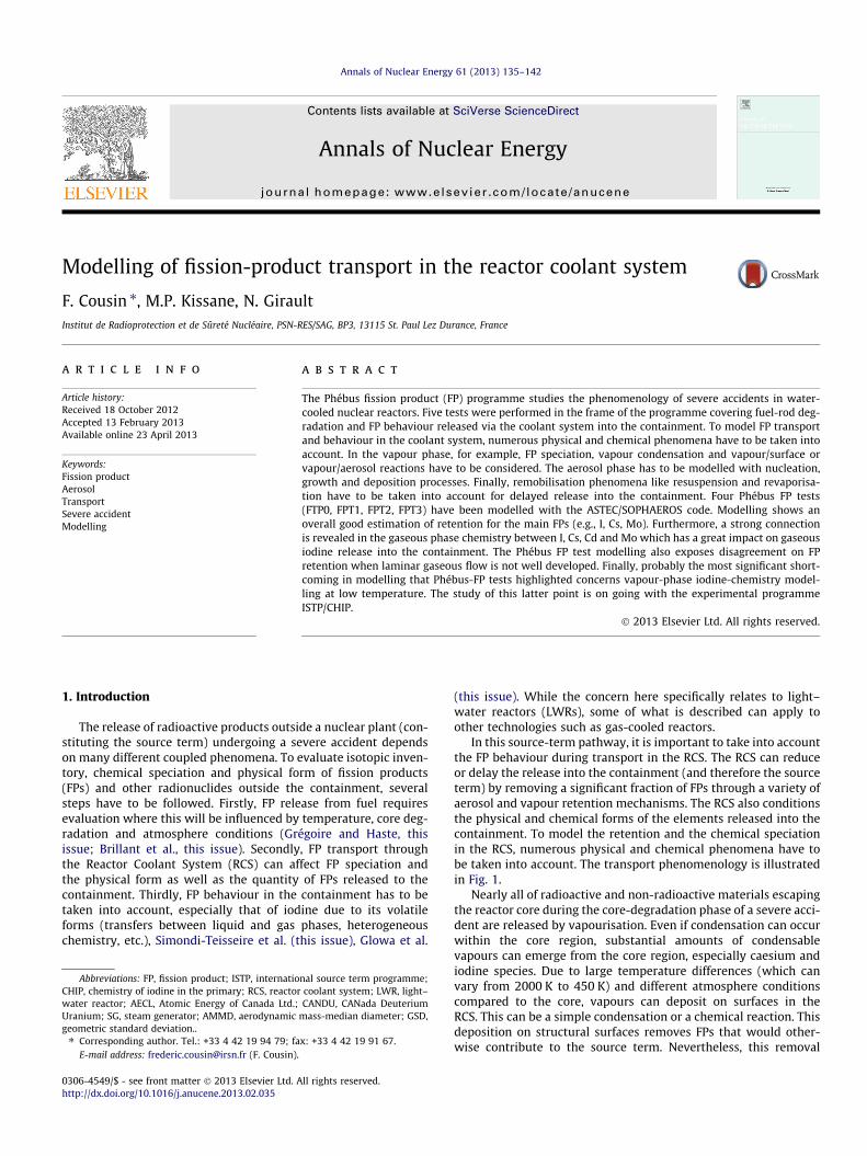
In this source-term pathway, it is important to take into accountthe FP behaviour during transport in the RCS. The RCS can reduceor delay the release into the containment (and therefore the sourceterm) by removing a significant fraction of FPs through a variety ofaerosol and vapour retention mechanisms. The RCS also conditionsthe physical and chemical forms of the elements released into thecontainment. To model the retention and the chemical speciationin the RCS, numerous physical and chemical phenomena have tobe taken into account. The transport phenomenology is illustratedin Fig. 1.
Nearly all of radioactive and non-radioactive materials escapingthe reactor core during the core-degradation phase of a severe acci-dent are released by vapourisation. Even if condensation can occurwithin the core region, substantial amounts of condensablevapours can emerge from the core region, especially caesium andiodine species. Due to large temperature differences (which canvary from 2000 K to 450 K) and different atmosphere conditionscompared to the core, vapours can deposit on surfaces in theRCS. This can be a simple condensation or a chemical reaction. Thisdeposition on structural surfaces removes FPs that would other-wise contribute to the source term. Nevertheless, this removal
Fig. 1. Idealised transport phenomenology of fission products and structural materials as flow cools in the RCS during a severe accident.
136 F. Cousin et al. / Annals of Nuclear Energy 61 (2013) 135–142
can be temporary since continued heating of the surface by con-vection or decay heat can revapourise condensed vapours; in addi-tion, more volatile species can evolve from the deposits due tochemical reactions especially if the gas-phase composition varies(e.g., from hydrogen rich to steam rich). Condensable vapourscan also lead to formation of aerosols and contribute to theirgrowth. Aerosols can also be deposited in the RCS due to severalphysical processes. The behaviour of an aerosol population in theRCS is, in particular, very sensitive to the size distribution of theparticles.
The Phebus FP programme (Von der Hardt and Tattegrain, 1992;Schwarz et al., 1999; Clément and Zeyen, this issue) investigatedLWR severe accidents by providing in-pile integral tests involvinga nearly-complete set of LWR severe-accident phenomena. Themain purpose of the programme was, by including interpretationof the tests with computer codes and models, to determinewhether any significant phenomena were being overlooked insource-term evaluations. Here, the data produced and their inter-pretations are especially helpful in improving the description andunderstanding of what happens during FP transport in the RCS.
The following discussion focuses on FP transport modelling.After a description of each phenomenon and possible modelling,several applications and results coming from Phebus programmewill be presented.
2. Vapour-phase phenomena
2.1. Vapour-phase chemistry
It is generally assumed that, at high temperature, thermody-namic chemical equilibrium in the gas phase is reached. Thisassumption provides the chemical speciation at a given tempera-ture, carrier-gas composition and concentrations of the differentvapour and gaseous species using an extensive thermochemicaldatabase (Kaye et al., 2010). Nevertheless, it is not possible toexplain the Phebus results, especially gaseous iodine released inthe containment, assuming chemical equilibrium in the gas phase(Kissane and Drosik, 2006). This is why possible chemical-kineticslimitations have to be taken into account in the gas-phasemodelling. In order to model these limitations, different iodinemechanisms have been considered (Xerri et al., 2012; Cantrelet al., this issue) for comparison with experimental results givenby the on-going ISTP/CHIP programme (Gouello et al., 2011).
2.2. Vapour condensation/evaporation on surfaces
Even if chemical equilibrium is not reached at low temperature,the time constant of gas-phase reactions is assumed to be suffi-ciently small compared with that of vapour condensation so that va-pour-phase chemistry is decoupled from other phenomena.Therefore the masses transferred between different phases are not
determined by equilibria, but are kinetics-controlled. The condensa-tion rate is proportional to a deviation from the equilibrium (i.e., thedifference between the partial pressure and the saturation pres-sure). This approach can also be used to describe revapourisation.
The condensation/evaporation velocities are calculated for eachvolatile species and wall (structural surface) by using the Chilton–Colburn analogy between heat and mass transfer.
2.3. Vapour condensation/evaporation onto aerosols
The condensation/evaporation rates onto aerosols can be de-scribed using a similar approach as that onto surfaces, though masstransfer is treated as purely diffusive. The condensation rate in thiscase will strongly depend on aerosol suspended mass and sizedistribution.
2.4. Vapour sorption
Sorption velocities are calculated for volatile species as a func-tion of wall temperature by using semi-empirical relationships.These are derived from experimental results used in the TRAPMELTcode (Elrick et al., 1984) or fitted from results of the DEVAP tests(Le Marois and Megnin, 1994) for CsOH, Te and SnTe or, notablyfor iodine species, came from the VICTORIA 2 code (Bixler, 1998)having been selected by AECL in the context of a collaborationbetween IRSN and the CANDU Owners’ Club (Dickson, 2001).
The trapping of volatile species by wall sorption can be dividedinto two steps: diffusive transport to the wall similar to thatinvolved in evaporation/condensation processes and sorption atthe surface.
Therefore, the equivalent wall sorption velocity is obtained byassuming that sorption and condensation/evaporation phenomenaact in parallel.
2.5. Homogeneous nucleation
Nucleation directly from vapour is usually predicted when theambient partial pressure of the condensable vapour exceeds theequilibrium partial pressure by about a factor of four. Quantitativeprediction of nucleation in the RCS is difficult. Pure nucleationtheories exist but it is difficult to extend them to multi-componentvapours. Existing theories predict that the nucleation rate is verysensitive to the surface free-energy of the embryonic nuclei. A goodcompromise between simplicity and accuracy (Martin, 1997) is theGirshick et al. (1990) model.
3. Aerosol phenomena
A comprehensive review of modelling techniques and experi-ments related to the nuclear-safety field has been provided byAllelein et al. (2009).
F. Cousin et al. / Annals of Nuclear Energy 61 (2013) 135–142 137
3.1. Aerosol size distribution
In the RCS, the aerosol population is polydisperse and charac-terised by a size class distribution. This distribution is driven bya general dynamic equation (Friedlander 1977; Seinfeld andPandis, 2006) which does not have an analytic solution. To solvethis equation, the distribution function is derived as a function ofthe particle diameter. Two approaches are generally used: themodal and sectional approaches.
In the modal approach, the distribution function is evaluatedusing analytic functions which represent the different domains orthe modes of the distribution. These analytic functions are arbi-trarily chosen. A lognormal function is commonly used (Binkowskiand Shankar 1995; Ackermann et al., 1998) where the number ofparticles, n, of diameter D is given by: nðln DÞ ¼ Nffiffiffiffi
2pp
lnrgexp
� ðln D�ln Dg Þ2
2ln2rg
� �where N is the total particle number concentration,
D, particle diameter and Dg and rg are respectively the geometricmedian diameter and standard deviation of the distribution.
The main limitation of this approach is that distribution form isimposed and the number of modes has to be chosen initially. Onthe other hand, the number of variables is reduced because onlythree variables (particle number, geometric median diameter andstandard deviation) are necessary to describe one mode.
In the sectional approach, the distribution function is describedby a finite number of size classes (Gelbard and Seinfeld, 1980;Gelbard et al., 1980). This description can be based on a distribu-tion function expressed in terms of the number, surface or volume(or mass). It depends on the goals of the study. In nuclear applica-tions, mass conservation is one of the most important parametersfor the correct evaluation of the source term. Therefore thedistribution function will be expressed in mass assuming constantaerosol density.
A comparison of different algorithms (Zhang et al., 1999) con-cluded that a sectional approach with a sufficient number of sizeclasses is more appropriate to study aerosol dynamics and physicalprocesses instead of the modal approach which is better suited to alarge-scale study.
3.2. Coagulation
When relative movements of aerosols bring particles into con-tact, they bind together as a result of surface free-energy or Vander Waals forces. Relative movements between aerosol particlescan be produced by three different mechanisms: Brownian motion,gravitational settling and turbulence.
For each phenomenon, the agglomeration kernels are calculatedbetween two particle size classes (i and j) in each control volume.
3.2.1. Brownian coagulationThe coagulation kernel Kb
i;j (m3 s�1) between two particle sizeclasses i and j can be given by the following relationship (Loyalka,1976; Williams and Loyalka, 1991):
Kbi;j ¼ 4pðri þ rjÞðDi
B þ DjBÞ
where DiB (m2 s�1) is the Brownian diffusivity of particle i, ri is the
radius of particle i.In this model, particles are considered spherical but a shape fac-
tor can be introduced. This model is applied in the continuum flowregime. For transition to the free molecular flow regime, anothermodel (Davies, 1966) is also available.
3.2.2. Gravitational agglomerationThe coagulation kernel Kg
i;j (m3 s�1) between two particle sizeclasses i and j is given by the following formula: Kg
i;j ¼ pc2nij
ðri þ rjÞ2jVsd;i � Vs
d;jj where c is the critical distance of initial separa-tion of the particles that will lead to grazing contact, nij is theagglomeration efficiency between particles of size classes i and j,
Kgi;j ¼ pc2nijðri þ rjÞ2j Vs
d;i � Vsd;jj is the gravitational-settling velocity
of particle size class i (m s�1).The formulation by Pruppacher and Klett (1978) can be used for
aerosol agglomeration efficiency in the RCS (other formulationshave been proposed that appear more realistic for particles largerthan those expected in the RCS, e.g., Buckley and Loyalka, 1995).
3.2.3. Turbulent agglomerationThe turbulent agglomeration kernel follows the Saffman and
Turner (1956) approach and is based on a quadratic combinationof the shear turbulent (sh) and inertial turbulent (in) kernels(Williams and Loyalka, 1991; Pruppacher and Klett, 1978)
The shear turbulent kernel Kshi;j (m3 s�1) is given by the following
relationship: Kshi;j ¼ 2
3 ðri þ rjÞ3ffiffiffiffiffiffiffiffi2pETmf
qwhere ET (m2 s�3) is the carrier
fluid turbulent dissipation energy density and mf (m2 s�1) is thecarrier fluid kinematic viscosity.
The inertial turbulent kernel Kini;j (m3 s�1) is determined by the
following relationship: Kini;j ¼ 2
ffiffiffiffiffiffiffi2pp c2
g nijðri þ rjÞ2jVsd;i � Vs
d;jjð8p15E3
TmfÞ1=4
where g is gravitational acceleration (m2 s�1).The resulting turbulent agglomeration kernel Kt
i;j (m3 s�1) isobtained by a quadratic combination.
3.3. Deposition
Due to several aerosol size classes, aerosol particles can bedeposited in the RCS by several phenomena. Aerosol particles aresmall enough to be affected by Brownian motion, temperature gra-dients, concentration gradients and electrostatic forces. They canbe also big enough to be separated from flow streams by inertiaor because of gravitational forces.
3.3.1. Brownian diffusionThe Brownian motion of particles is produced by stochastic
impulses imparted by collisions with gas molecules. Brownianmotion induces a diffusive behaviour of aerosol particles. Browniandiffusion is directly linked with the particle Brownian diffusivity:DB ¼ Cn�k�T
6p�l�r where Cn is the Cunningham slip correction factor, Tand l are the temperature and viscosity of the gas, k, Boltzmann’sconstant and r, particle radius. Consequently, deposition of aerosolparticles by diffusion is most important for very small particles(<0.1 lm).
3.3.2. ThermophoresisTemperature gradients in the gas phase can impart a net veloc-
ity to aerosol particles in a direction opposite to the gradient. TheTalbot formulation (Talbot et al., 1980) is widely used to calculateparticle deposition velocity Vth
d (m s�1):
Vthd ¼ �
mf
Tf
dTw
dr
2Cskf
kpþ CtKn
� �Cn
ð1þ 3CmKnÞ 1þ 2ðkf
kpþ CtKnÞ
h i fordTw
dr6 0
where dTwdr (K m�1) is the wall-fluid temperature gradient, mf (m2 s�1)
is the carrier-fluid kinematics viscosity, Tf (K) is the fluid tempera-ture, mf (J s�1 m�1 K�1) is the carrier-fluid thermal conductivity, mf
(J s�1 m�1 K�1) is the particle thermal conductivity, tSt is the mo-ment accommodation coefficient; tSt is the thermal-slip coefficient,tSt is the thermal accommodation coefficient and Kn is the Knudsennumber (the ratio of the molecular mean free path to particleradius).
138 F. Cousin et al. / Annals of Nuclear Energy 61 (2013) 135–142
3.3.3. DiffusiophoresisThe fluxes of condensing or chemically-reacting vapours
towards surfaces in the RCS can sweep along aerosol particles.The Waldmann (1961) model can be used to calculate the particlediffusiophoretic deposition velocity. This is based on the Stefanvelocity (Williams and Loyalka, 1991) with a correction factor(Waldmann, 1961). The very simple formulation of the correctionfactor is based on a theoretical approach which is consistent withthe free molecular regime and leads to a deposition velocity inde-pendent of the particle size.
3.3.4. Turbulent diffusionThis deposition mechanism is active only for turbulent flow
regimes, i.e., for Reynolds number higher than 2300 (Rew > 2300,transitional flows are not considered). The Davies formulation (Da-vies, 1966) can be used to calculate particle deposition velocity.
3.3.5. Gravitational settlingAerosol particles can settle on surfaces due to gravity. The
particle settling velocity is deduced from the Stokes velocity andvaries with the square of the particle diameter. Consequently, grav-itational settling is more important for large particles (>1 lm).
3.3.6. Convective deposition mechanismsDue to their inertia which limits their ability to follow the
carrier-gas flow, aerosol particles deposit on surfaces as a flowpasses through bends, sudden contractions or expansions in theflow channel whether the flow is laminar or turbulent. Because thisdeposition is due to aerosol inertia, it increases with aerosol sizeand flow velocity. However, high-velocity flows (leading to highparticle impact velocities) and particle materials of low elasticitycan produce particle bounce, i.e., the inertia-induced particle–sur-face impact cannot be considered to have a sticking efficiencyequal to unity. This phenomenon has been investigated for a longtime (e.g., Dahneke, 1973) and, while it may be relevant to specificaccident sequences producing the relevant conditions, it is not astandard feature of RCS modelling.
Turbulent eddy-impaction deposition can be calculated withthe empirically-based model of Liu and Agarwal (1974).
Due to tortuous pathways in the RCS, deposition in bends isimportant in the analysis of aerosol behaviour. To cover the rangeof conditions encountered, it is common in a model to combineseveral relationships giving the particle transmission efficiency,e.g., in bends of circular section, the experiments of Pui et al.(1987) for laminar and turbulent (Re = 10,000) flows are of interest.The choice of relationship depends on criteria that are functions ofthe flow Reynolds number or particle Stokes number. These criteriaare determined from experimental data and theoretical work.
For impaction in contractions, Ye and Pui (1990) and Chen andPui (1995) provide a simple expression for deposition efficiency interms of the Stokes number, the contraction ratio and the contrac-tion angle. The Ye and Pui model was developed for sudden (i.e.,90�) contractions but is also valid for less sudden ones. It is to benoted that these models are proposed for laminar flow but sometesting of the sudden contraction model in turbulent conditionsshows it to be credible (Ye and Pui, 1990).
3.4. Mechanical resuspension
Deposited aerosols can be resuspended if there is a significantacceleration in flow conditions. This mechanical resuspension hasto be taken into account since it restores deposited aerosols tothe fluid system; resuspended aerosols may contribute to an in-crease in the source term.
Mechanical resuspension takes place essentially for turbulentfluid flow conditions and is inhibited by humidity: the surrounding
atmosphere, the deposition surface, and the aerosol deposit itselfshould be dry for optimal resuspension. A first approach to com-pute resuspension compares forces acting on deposited aerosolswith aerodynamic removal forces. Resuspension occurs when theaerodynamic removal forces exceed the adhesive forces attachingthe particle to the surface. This force-balance approach gives noinformation on kinetics since a particle either meets the resuspen-sion criterion and resuspends or remains deposited. An alternativemodel can be applied giving information on kinetics which is basedon energy transfer between a turbulent gas flow and a depositedparticle and the drag force generating a moment about the pointof attachment: this is the rock’n’roll model (Reeks and Hall,2001). The particle is assumed to have only two points of contactwith the surface. Under the influence of fluctuating aerodynamicforces, the particle oscillates around the second point until it accu-mulates sufficient rotational energy to leave the first point defini-tively. Significant improvements have recently been made to therock’n’roll approach leading to greater realism and improvedagreement with kinetic data (Zhang et al., 2013).
4. Phebus test applications
Four Phebus tests (FPT0, FPT1, FPT2, FPT3) have been modelledwith several FP transport codes. One of them, the SOPHAEROSmodule (Cousin et al., 2008) developed at IRSN was applied to helpunderstand FP transport behaviour in the RCS.
SOPHAEROS is one of the modules in the ASTEC severe accidentcode (van Dorsselaere et al., 2003). This module takes account of allthe different phenomena presented in the previous section. It wasused to model each Phebus test: Kissane and Drosik (2006) studiedespecially the FPT0 and FPT1 tests whereas Girault et al. (2010) fo-cused on the FPT2 test; the FPT3 test was also modelled. Generalconclusions focusing on aerosol transport and overall depositionare presented in this section. Chemistry aspects in the RCS of thePhebus tests are the focus in Girault and Payot (this issue).
4.1. Global features
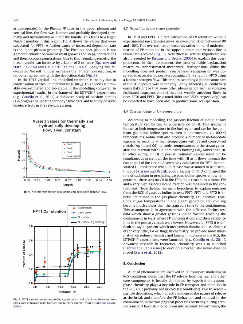
4.1.1. Overall retention in the RCSFP transport modelling of the various phenomena in the Phebus
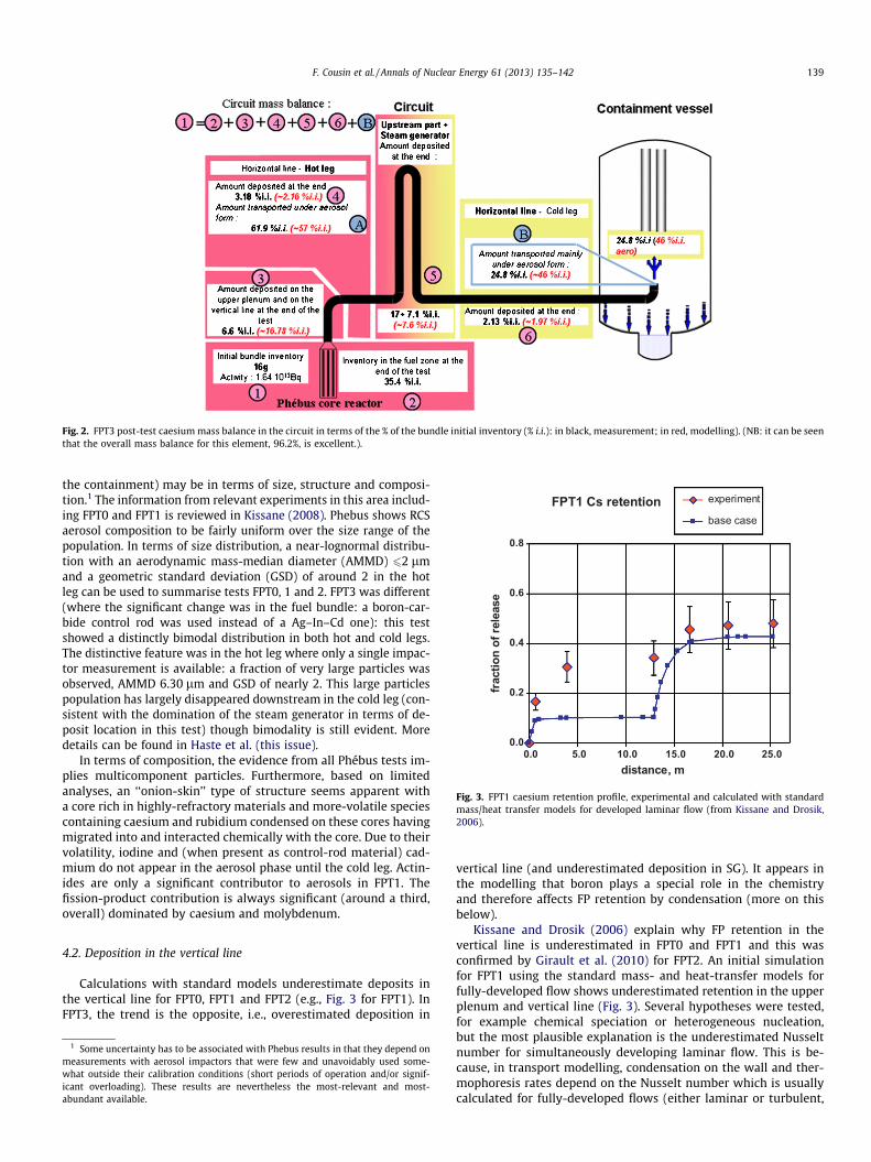
FP tests correctly reproduces overall retention in the RCS for testsFPT0, FPT1 and FPT2, e.g., Fig. 3 (from Kissane and Drosik, 2006)shows this result for caesium. Fig. 3 also highlights the two mainparts of the RCS that play a significant role in the FP retention:the upper plenum with the vertical line in the hot part of the circuitand the steam generator (SG) in the cold part. This overall retentionis less well reproduced in FPT3 where Fig. 2 presents the caesiummass balance for this test. Again, caesium retention mainly occursin the upper plenum and vertical line and in the SG but, for this test,the SG deposition dominated in the test (a total of 24.1% of the ini-tial bundle inventory). It is important to note that after about14,500 s into the FPT3 transient there is evidence that a significantbut varying partial flow blockage appeared in the SG (see Hasteet al., this issue) which must have enhanced FP retention in the up-stream SG. This partial blockage, rich in boron, cannot be repro-duced by the current standard modelling: in the SG, modellingpredicts retention due to condensation just at the entrance of SG;afterwards, retention is due mainly to aerosol deposition by ther-mophoresis. Therefore, while the modelling does show the mainretention to be in the vertical line and steam generator, not repro-ducing the partial blockage and its consequences contributes lar-gely to an overall retention which is lower than in the test (Fig. 2).
4.1.2. Aerosol characteristics in the RCSThe Phebus FP tests added a great deal of information on what
the prototypical characteristics of aerosol particles in the RCS (and
FPT1 Cs retention
0.0
0.2
0.4
0.6
0.8
0.0 5.0 10.0 15.0 20.0 25.0distance, m
frac
tion
of re
leas
eexperiment
base case
Fig. 3. FPT1 caesium retention profile, experimental and calculated with standardmass/heat transfer models for developed laminar flow (from Kissane and Drosik,2006).
Fig. 2. FPT3 post-test caesium mass balance in the circuit in terms of the % of the bundle initial inventory (% i.i.): in black, measurement; in red, modelling). (NB: it can be seenthat the overall mass balance for this element, 96.2%, is excellent.).
F. Cousin et al. / Annals of Nuclear Energy 61 (2013) 135–142 139
the containment) may be in terms of size, structure and composi-tion.1 The information from relevant experiments in this area includ-ing FPT0 and FPT1 is reviewed in Kissane (2008). Phebus shows RCSaerosol composition to be fairly uniform over the size range of thepopulation. In terms of size distribution, a near-lognormal distribu-tion with an aerodynamic mass-median diameter (AMMD) 62 lmand a geometric standard deviation (GSD) of around 2 in the hotleg can be used to summarise tests FPT0, 1 and 2. FPT3 was different(where the significant change was in the fuel bundle: a boron-car-bide control rod was used instead of a Ag–In–Cd one): this testshowed a distinctly bimodal distribution in both hot and cold legs.The distinctive feature was in the hot leg where only a single impac-tor measurement is available: a fraction of very large particles wasobserved, AMMD 6.30 lm and GSD of nearly 2. This large particlespopulation has largely disappeared downstream in the cold leg (con-sistent with the domination of the steam generator in terms of de-posit location in this test) though bimodality is still evident. Moredetails can be found in Haste et al. (this issue).
In terms of composition, the evidence from all Phébus tests im-plies multicomponent particles. Furthermore, based on limitedanalyses, an ‘‘onion-skin’’ type of structure seems apparent witha core rich in highly-refractory materials and more-volatile speciescontaining caesium and rubidium condensed on these cores havingmigrated into and interacted chemically with the core. Due to theirvolatility, iodine and (when present as control-rod material) cad-mium do not appear in the aerosol phase until the cold leg. Actin-ides are only a significant contributor to aerosols in FPT1. Thefission-product contribution is always significant (around a third,overall) dominated by caesium and molybdenum.
4.2. Deposition in the vertical line
Calculations with standard models underestimate deposits inthe vertical line for FPT0, FPT1 and FPT2 (e.g., Fig. 3 for FPT1). InFPT3, the trend is the opposite, i.e., overestimated deposition in
1 Some uncertainty has to be associated with Phebus results in that they depend onmeasurements with aerosol impactors that were few and unavoidably used some-what outside their calibration conditions (short periods of operation and/or signif-icant overloading). These results are nevertheless the most-relevant and most-abundant available.
vertical line (and underestimated deposition in SG). It appears inthe modelling that boron plays a special role in the chemistryand therefore affects FP retention by condensation (more on thisbelow).
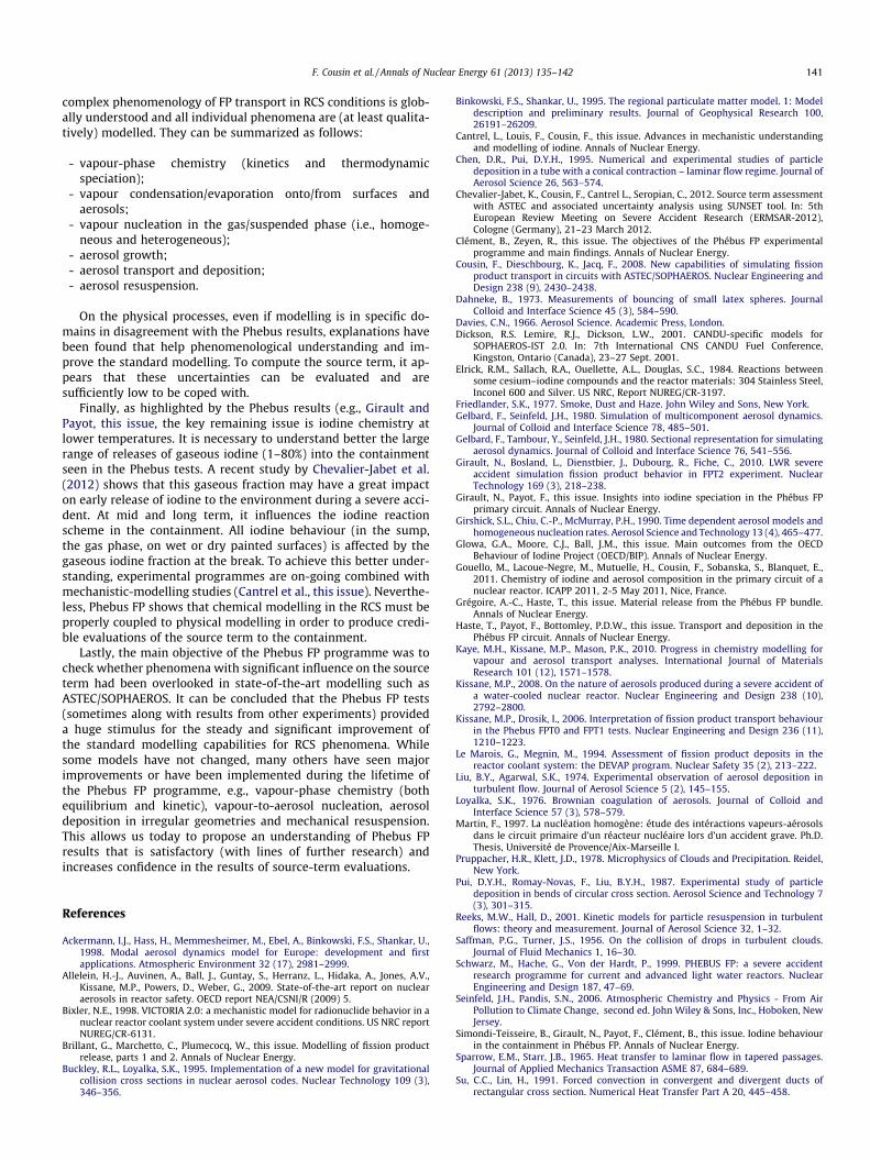
Kissane and Drosik (2006) explain why FP retention in thevertical line is underestimated in FPT0 and FPT1 and this wasconfirmed by Girault et al. (2010) for FPT2. An initial simulationfor FPT1 using the standard mass- and heat-transfer models forfully-developed flow shows underestimated retention in the upperplenum and vertical line (Fig. 3). Several hypotheses were tested,for example chemical speciation or heterogeneous nucleation,but the most plausible explanation is the underestimated Nusseltnumber for simultaneously developing laminar flow. This is be-cause, in transport modelling, condensation on the wall and ther-mophoresis rates depend on the Nusselt number which is usuallycalculated for fully-developed flows (either laminar or turbulent,
140 F. Cousin et al. / Annals of Nuclear Energy 61 (2013) 135–142
as appropriate). In the Phebus FP case, in the upper plenum andvertical line, the flow was laminar and probably developed ther-mally and hydraulically as it left the bundle. This leads to a largerNusselt number in this region: Fig. 4 shows the values that werecalculated for FPT1. A further cause of increased deposition rateis the upper plenum geometry. The Phebus upper plenum is nota smooth cylinder because of small grooves and steps, contractionsand thermocouple penetrations. Due to this irregular geometry, themass transfer can increase by a factor of 2 or more (Sparrow andStarr, 1965; Su and Lin, 1991; Tao et al., 2002). Applying this re-evaluated Nusselt number increases the FP retention resulting infar better agreement with the deposition data (Fig. 5).
In the FPT3 vertical line, modelled retention is mainly due tocondensation of caesium metaborate (CsBO2). This species is prob-ably overestimated and too stable in the modelling compared toexperimental results. In the frame of the ISTP/CHIP experiments(e.g., Gouello et al., 2011), a dedicated study of caesium boratesis in progress to update thermodynamic data and to study possiblekinetic effects in the relevant system.
Fig. 4. Nusselt number for developing and developed laminar flow.
FPT1 Cs retention
0.0
0.2
0.4
0.6
0.8
0.0 5.0 10.0 15.0 20.0 25.0distance, m
frac
tion
of re
leas
e
experimentbase caseNu undev.Nu undev. + geometry
Fig. 5. FPT1 caesium retention profile, experimental and calculated (base and twocases with enhanced mass transfer due to entry effects) (from Kissane and Drosik,2006).
4.3. Deposition in the steam generator
In FPT0 and FPT1, a direct calculation of FP retention withoutexperimental uncertainties gives an over-prediction between% 80and 100%. This overestimation becomes rather minor if underesti-mation of FP retention in the upper plenum and vertical line istaken into account (Fig. 5). Nevertheless, several hypotheses arealso presented by Kissane and Drosik (2006) to explain this over-prediction. In their assessment, the most probable explanationrelates to underestimated mechanical resuspension. While themodelling does not predict resuspension, resuspension was ob-served to occur during post-test purging of the circuit in FPT0 usinga laminar nitrogen flow. This implies two things: (i) that some partof the SG deposits was either very lightly adhered (i.e., could veryeasily flake off) or that some other phenomenon such as vibrationfacilitated resuspension; (ii) that the weakly turbulent flows intests FPT0 and FPT1 (Re around 4800 and 3500, respectively) canbe expected to have been able to produce some resuspension.
4.4. Gaseous iodine at low temperature
According to modelling, the gaseous fraction of iodine at lowtemperature can be due to a persistence of HI. This species isformed at high temperature in the fuel region and can be the dom-inant gas-phase iodine species even at intermediate (�1000 K)temperatures. Iodine will also produce a number of metal-iodidevapours by reacting at high temperature with Cs and control-rodmetals (Ag, In and Cd); at cooler temperatures in the steam gener-ator, the reaction with Cd dominates forming CdI2 rather than HI.In other words, for HI to persist, cadmium vapour must not besimultaneous present all the time with HI as it flows through thecooler part of the circuit. A sensitivity calculation for FPT1 demon-strated HI persistence when Cd release was assumed to be discon-tinuous (Kissane and Drosik, 2006). Results of FPT3 confirmed therole of cadmium in precluding gaseous iodine species at low tem-perature: there was no Cd in the FP bundle (except as a minor FP)and a very high gaseous iodine fraction was measured in the con-tainment. Nevertheless, the main hypothesis to explain emissionfrom the RCS of gaseous iodine in tests FPT0, FPT1 and FPT2 is ki-netic limitations in the gas-phase chemistry, i.e., chemical reac-tions at gas temperatures in the steam generator and cold legbecome much slower than the transport time to the containment.This assumption is in agreement with the different Phebus testdata which show a greater gaseous iodine fraction reaching thecontainment in tests where FP concentrations and their residencetime in the primary circuit were lowest. However, for FPT3 it is dif-ficult to say at present which mechanism dominated, i.e., absenceof (or very little) Cd or sluggish chemistry. To provide more infor-mation on iodine chemistry and kinetic limitations in the RCS, theISTP/CHIP experiments were launched (e.g., Gouello et al., 2011).Advanced research in theoretical chemistry was also launched(Cantrel et al., this issue) to develop a mechanistic iodine-kineticsmodel (Xerri et al., 2012).
5. Conclusion
A lot of phenomena are involved in FP transport modelling inRCS conditions. Given that the FP release from the fuel and othercore components is heavily dominated by vaporisation, vapour-phase chemistry plays a key role in FP transport and retention inthe RCS (but probably not in cold leg conditions). Due to aerosol-particle deposition, which directly influences the nature of releaseat the break and therefore the FP behaviour and removal in thecontainment, numerous physical processes occurring during aero-sol transport have also to be taken into account. Nevertheless, the
F. Cousin et al. / Annals of Nuclear Energy 61 (2013) 135–142 141
complex phenomenology of FP transport in RCS conditions is glob-ally understood and all individual phenomena are (at least qualita-tively) modelled. They can be summarized as follows:
- vapour-phase chemistry (kinetics and thermodynamicspeciation);
- vapour condensation/evaporation onto/from surfaces andaerosols;
- vapour nucleation in the gas/suspended phase (i.e., homoge-neous and heterogeneous);
- aerosol growth;- aerosol transport and deposition;- aerosol resuspension.
On the physical processes, even if modelling is in specific do-mains in disagreement with the Phebus results, explanations havebeen found that help phenomenological understanding and im-prove the standard modelling. To compute the source term, it ap-pears that these uncertainties can be evaluated and aresufficiently low to be coped with.
Finally, as highlighted by the Phebus results (e.g., Girault andPayot, this issue, the key remaining issue is iodine chemistry atlower temperatures. It is necessary to understand better the largerange of releases of gaseous iodine (1–80%) into the containmentseen in the Phebus tests. A recent study by Chevalier-Jabet et al.(2012) shows that this gaseous fraction may have a great impacton early release of iodine to the environment during a severe acci-dent. At mid and long term, it influences the iodine reactionscheme in the containment. All iodine behaviour (in the sump,the gas phase, on wet or dry painted surfaces) is affected by thegaseous iodine fraction at the break. To achieve this better under-standing, experimental programmes are on-going combined withmechanistic-modelling studies (Cantrel et al., this issue). Neverthe-less, Phebus FP shows that chemical modelling in the RCS must beproperly coupled to physical modelling in order to produce credi-ble evaluations of the source term to the containment.
Lastly, the main objective of the Phebus FP programme was tocheck whether phenomena with significant influence on the sourceterm had been overlooked in state-of-the-art modelling such asASTEC/SOPHAEROS. It can be concluded that the Phebus FP tests(sometimes along with results from other experiments) provideda huge stimulus for the steady and significant improvement ofthe standard modelling capabilities for RCS phenomena. Whilesome models have not changed, many others have seen majorimprovements or have been implemented during the lifetime ofthe Phebus FP programme, e.g., vapour-phase chemistry (bothequilibrium and kinetic), vapour-to-aerosol nucleation, aerosoldeposition in irregular geometries and mechanical resuspension.This allows us today to propose an understanding of Phebus FPresults that is satisfactory (with lines of further research) andincreases confidence in the results of source-term evaluations.
References
Ackermann, I.J., Hass, H., Memmesheimer, M., Ebel, A., Binkowski, F.S., Shankar, U.,1998. Modal aerosol dynamics model for Europe: development and firstapplications. Atmospheric Environment 32 (17), 2981–2999.
Allelein, H.-J., Auvinen, A., Ball, J., Guntay, S., Herranz, L., Hidaka, A., Jones, A.V.,Kissane, M.P., Powers, D., Weber, G., 2009. State-of-the-art report on nuclearaerosols in reactor safety. OECD report NEA/CSNI/R (2009) 5.
Bixler, N.E., 1998. VICTORIA 2.0: a mechanistic model for radionuclide behavior in anuclear reactor coolant system under severe accident conditions. US NRC reportNUREG/CR-6131.
Brillant, G., Marchetto, C., Plumecocq, W., this issue. Modelling of fission productrelease, parts 1 and 2. Annals of Nuclear Energy.
Buckley, R.L., Loyalka, S.K., 1995. Implementation of a new model for gravitationalcollision cross sections in nuclear aerosol codes. Nuclear Technology 109 (3),346–356.
Binkowski, F.S., Shankar, U., 1995. The regional particulate matter model. 1: Modeldescription and preliminary results. Journal of Geophysical Research 100,26191–26209.
Cantrel, L., Louis, F., Cousin, F., this issue. Advances in mechanistic understandingand modelling of iodine. Annals of Nuclear Energy.
Chen, D.R., Pui, D.Y.H., 1995. Numerical and experimental studies of particledeposition in a tube with a conical contraction – laminar flow regime. Journal ofAerosol Science 26, 563–574.
Chevalier-Jabet, K., Cousin, F., Cantrel L., Seropian, C., 2012. Source term assessmentwith ASTEC and associated uncertainty analysis using SUNSET tool. In: 5thEuropean Review Meeting on Severe Accident Research (ERMSAR-2012),Cologne (Germany), 21–23 March 2012.
Clément, B., Zeyen, R., this issue. The objectives of the Phébus FP experimentalprogramme and main findings. Annals of Nuclear Energy.
Cousin, F., Dieschbourg, K., Jacq, F., 2008. New capabilities of simulating fissionproduct transport in circuits with ASTEC/SOPHAEROS. Nuclear Engineering andDesign 238 (9), 2430–2438.
Dahneke, B., 1973. Measurements of bouncing of small latex spheres. JournalColloid and Interface Science 45 (3), 584–590.
Davies, C.N., 1966. Aerosol Science. Academic Press, London.Dickson, R.S. Lemire, R.J., Dickson, L.W., 2001. CANDU-specific models for
SOPHAEROS-IST 2.0. In: 7th International CNS CANDU Fuel Conference,Kingston, Ontario (Canada), 23–27 Sept. 2001.
Elrick, R.M., Sallach, R.A., Ouellette, A.L., Douglas, S.C., 1984. Reactions betweensome cesium–iodine compounds and the reactor materials: 304 Stainless Steel,Inconel 600 and Silver. US NRC, Report NUREG/CR-3197.
Friedlander, S.K., 1977. Smoke, Dust and Haze. John Wiley and Sons, New York.Gelbard, F., Seinfeld, J.H., 1980. Simulation of multicomponent aerosol dynamics.
Journal of Colloid and Interface Science 78, 485–501.Gelbard, F., Tambour, Y., Seinfeld, J.H., 1980. Sectional representation for simulating
aerosol dynamics. Journal of Colloid and Interface Science 76, 541–556.Girault, N., Bosland, L., Dienstbier, J., Dubourg, R., Fiche, C., 2010. LWR severe
accident simulation fission product behavior in FPT2 experiment. NuclearTechnology 169 (3), 218–238.
Girault, N., Payot, F., this issue. Insights into iodine speciation in the Phébus FPprimary circuit. Annals of Nuclear Energy.
Girshick, S.L., Chiu, C.-P., McMurray, P.H., 1990. Time dependent aerosol models andhomogeneous nucleation rates. Aerosol Science and Technology 13 (4), 465–477.
Glowa, G.A., Moore, C.J., Ball, J.M., this issue. Main outcomes from the OECDBehaviour of Iodine Project (OECD/BIP). Annals of Nuclear Energy.
Gouello, M., Lacoue-Negre, M., Mutuelle, H., Cousin, F., Sobanska, S., Blanquet, E.,2011. Chemistry of iodine and aerosol composition in the primary circuit of anuclear reactor. ICAPP 2011, 2-5 May 2011, Nice, France.
Grégoire, A.-C., Haste, T., this issue. Material release from the Phébus FP bundle.Annals of Nuclear Energy.
Haste, T., Payot, F., Bottomley, P.D.W., this issue. Transport and deposition in thePhébus FP circuit. Annals of Nuclear Energy.
Kaye, M.H., Kissane, M.P., Mason, P.K., 2010. Progress in chemistry modelling forvapour and aerosol transport analyses. International Journal of MaterialsResearch 101 (12), 1571–1578.
Kissane, M.P., 2008. On the nature of aerosols produced during a severe accident ofa water-cooled nuclear reactor. Nuclear Engineering and Design 238 (10),2792–2800.
Kissane, M.P., Drosik, I., 2006. Interpretation of fission product transport behaviourin the Phebus FPT0 and FPT1 tests. Nuclear Engineering and Design 236 (11),1210–1223.
Le Marois, G., Megnin, M., 1994. Assessment of fission product deposits in thereactor coolant system: the DEVAP program. Nuclear Safety 35 (2), 213–222.
Liu, B.Y., Agarwal, S.K., 1974. Experimental observation of aerosol deposition inturbulent flow. Journal of Aerosol Science 5 (2), 145–155.
Loyalka, S.K., 1976. Brownian coagulation of aerosols. Journal of Colloid andInterface Science 57 (3), 578–579.
Martin, F., 1997. La nucléation homogène: étude des intéractions vapeurs-aérosolsdans le circuit primaire d’un réacteur nucléaire lors d’un accident grave. Ph.D.Thesis, Université de Provence/Aix-Marseille I.
Pruppacher, H.R., Klett, J.D., 1978. Microphysics of Clouds and Precipitation. Reidel,New York.
Pui, D.Y.H., Romay-Novas, F., Liu, B.Y.H., 1987. Experimental study of particledeposition in bends of circular cross section. Aerosol Science and Technology 7(3), 301–315.
Reeks, M.W., Hall, D., 2001. Kinetic models for particle resuspension in turbulentflows: theory and measurement. Journal of Aerosol Science 32, 1–32.
Saffman, P.G., Turner, J.S., 1956. On the collision of drops in turbulent clouds.Journal of Fluid Mechanics 1, 16–30.
Schwarz, M., Hache, G., Von der Hardt, P., 1999. PHEBUS FP: a severe accidentresearch programme for current and advanced light water reactors. NuclearEngineering and Design 187, 47–69.
Seinfeld, J.H., Pandis, S.N., 2006. Atmospheric Chemistry and Physics - From AirPollution to Climate Change, second ed. John Wiley & Sons, Inc., Hoboken, NewJersey.
Simondi-Teisseire, B., Girault, N., Payot, F., Clément, B., this issue. Iodine behaviourin the containment in Phébus FP. Annals of Nuclear Energy.
Sparrow, E.M., Starr, J.B., 1965. Heat transfer to laminar flow in tapered passages.Journal of Applied Mechanics Transaction ASME 87, 684–689.
Su, C.C., Lin, H., 1991. Forced convection in convergent and divergent ducts ofrectangular cross section. Numerical Heat Transfer Part A 20, 445–458.

142 F. Cousin et al. / Annals of Nuclear Energy 61 (2013) 135–142
Talbot, L., Cheng, R.K., Schefer, R.W., Willis, D.R., 1980. Thermophoresis of particlesin a heated boundary layer. Journal of Fluid Mechanics 101, 737–758.
Tao, W.Q., Guo, Z.Y., Wang, B.X., 2002. Field synergy principle for enhancingconvective heat transfer – its extension and numerical verifications.International Journal of Heat and Mass Transfer 45, 3849–3856.
Van Dorsselaere, J.P., Jacq, F., Allelein, H.J., Schwinges, B., 2003. ASTEC code statusand applications. In: US NRC CSARP Meeting, Bethesda, USA, 5–7 May 2003.
Von der Hardt, P., Tattegrain, A., 1992. The Phebus fission product project. J. Nucl.Mater. 188 (C), 115–130.
Waldmann, L.Z., 1961. On the Motion of Spherical Particles in Non-HomogeneousGases. Rarefied Gas Dynamics, Academic Press, New York.
Williams, M.M.R., Loyalka, S.K., 1991. Aerosol Science – Theory and Practice.Pergamon Press, New York.
Xerri, B., Canneaux, S., Louis, F., Trincal, J., Cousin, F., Badawi, M., Cantrel, L., 2012. Abinitio calculations and iodine kinetic modeling in the reactor coolant system ofa pressurized water reactor in case of severe nuclear accident. Computationaland Theoretical Chemistry 990, 194–208.
Ye, Y., Pui, D.Y.H., 1990. Particle deposition in a tube with an abrupt contraction.Journal of Aerosol Science 21, 29–40.
Zhang, F., Reeks, M., Kissane, M.P., 2013. Particle resuspension in turbulentboundary layers and the influence of non-Gaussian removal forces. Journal ofAerosol Science, http://dx.doi.org/10.1016/j.jaerosci.2012.11.009.
Zhang, Y., Seigneur, C., Seinfeld, J.H., Jacobson, M.Z., Binkowski, F.S., 1999.Simulation of aerosol dynamics: a comparative review of algorithms used inair quality models. Aerosol Science and Technology 31, 487–514.