Embed Size (px)
Citation preview

457
Degradation of a LDPE film applied as a greenhouse cover design material: the effect of ageing and mechanical modelling
Degradación de un film de LDPE aplicado como material para el diseño de cubiertas de invernadero: efecto del envejecimiento y modelización mecánica
Eduardo Garzón (Main and Corresponding Author)
Universidad de Almería, Departamento de Ingeniería La Cañada de San Urbano s/n, 04120 Almería (Spain) [email protected]
Isabel María Ortiz Rodríguez Universidad de Almería, Departamento de Matemáticas La Cañada de San Urbano s/n, 04120 Almería (Spain) [email protected]
José Castillo Universidad Autónoma de Chapingo Km 38.5 Carretera México-Texcoco. Chapingo (Mexico) [email protected]
Pedro José Sánchez-Soto Universidad de Sevilla, Instituto de Ciencia de Materiales de Sevilla (ICMS) Centro Mixto Agencia Estatal Consejo Superior de Investigaciones Científicas (CSIC) c/ Américo Vespucio 49, Isla de la Cartuja, Parque Científico y Tecnológico Cartuja’93, 41092 Sevilla (Spain) [email protected] Manuscript Code: 1085 Date of Acceptance/Reception: 23.11.2018/13.03.2018 DOI: 10.7764/RDLC.17.3.457 Abstract In this work, we studied the mechanical performance of an LDPE film (0.22 mm in thickness) used as a material in the design of greenhouse covers. We investigated the effects of ageing at different periods of its service life and applying chemical substance treatments used as pesticides on greenhouse crops and after breakage using mechanical traction. Numerical simulations were performed using the finite element method. For this purpose, one section of the complete geometry of the greenhouse cover and different load conditions (1-5 kPa) were considered for the modelling. The performance of the polymer was assumed to be linearly elastic to simplify the governing equations. The study demonstrated that the LDPE film used was no longer effective as a greenhouse cover film due to the degradation of its mechanical properties. It was shown that the general performance of this film was in the plastic zone and its performance was non-linear. The results deduced from the present study are of interest because they show the material failure process of greenhouse covers in relation to the degradation process. Keywords: LDPE films, greenhouse covers, degradation, finite elements, mechanical properties. Resumen En este trabajo hemos estudiado el comportamiento mecánico de un film de LDPE (0.22 mm de espesor) usado como material para el diseño de cubiertas de invernaderos. Se ha investigado el efecto del envejecimiento en diferentes períodos de la vida útil, en los que se han aplicado tratamientos con sustancias químicas, utilizadas como pesticidas en cultivos de invernadero y después de la rotura mediante tracción mecánica. Las simulaciones numéricas se realizaron utilizando el método de elementos finitos. Para la modelización se ha considerado una sección de la geometría completa de la cubierta y diferentes condiciones de carga (1-5 kPa). Además, se asumió que el rendimiento del polímero era linealmente elástico para simplificar las ecuaciones. El estudio demostró que el film no estaba en condiciones de ser usado en la cubierta del invernadero debido a la pérdida de sus propiedades mecánicas. También se ha observado que el comportamiento general de la cubierta está en la zona plástica del material y, por tanto, tiene un comportamiento no lineal. Los resultados de las comparaciones realizadas son interesantes y de gran ayuda para ilustrar el proceso de falla del material de las cubiertas de invernadero en relación con el proceso de degradación. Palabras clave: films de LDPE, cubiertas de invernadero, degradación, elementos finitos, propiedades mecánicas.
Introduction: problem description and state of the art Scant information is available in the literature on the mechanical performance of low-density polyethylene (LDPE) under greenhouse film-cover working conditions (Briassoulis, 2004). Different experimental studies have measured the main parameters for characterizing this performance (Briassoulis & Schettini, 2000). However, to understand the tearing or

458
breaking, it was necessary to measure the stress and deformation of the material as well as its location. This task is highly complex and expensive to undertake experimentally since it requires the construction of model greenhouses, a large number of sensors and wind tunnels to generate the appropriate load conditions. Consequently, alternatives are sought to determine the stress and deformation. A widely used alternative is a stress-deformation numerical simulation because, in recent decades, the use of computers has facilitated mathematical simulation models, where governing equations are solved employing different methods, such as finite elements, finite differences, or finite volume (Fragos, Psychoudaki, & Malamataris, 1997; Reichrath & Davies, 2002; Mistriotis & Briassoulis, 2002; Tieleman, 2003; Shklyar & Arbel, 2004). Amongst these methods, the finite element method is the most widely used, as it offers the greatest versatility for these types of problems. Numerical simulation requires the characterization of the material’s mechanical properties, such as the elastic modulus, Poisson’s ratio, the fluence limit and elongation at break. These data are generally determined in laboratory tests made under standardized assays (Dilara & Briassoulis, 1998; Briassoulis, Aristopoulou, & Vitali, 2000). The most common of these is the ASTM D882 standard (ASTM D882, 1991) or its equivalent, ISO 527-3 (ISO 527-3, 1995), which is appropriate for films of less than 0.25 mm thickness and test specimens in the form of strips (Briassoulis & Aristopoulou, 2001). The mechanical performance of LDPE films in different combinations of strain and uniform pressure is investigated experimentally and numerically using the finite-element method. The properties of the materials used in the numerical models are based on measurements of the corresponding mechanical characteristics of the samples, performed in the laboratory using normalized methods. The comparisons are made between the numerical analysis and the experimental results obtained by the normalized procedure. The strain-deformation curve of the LDPE films, determined by tensile testing, provides information on the material’s elastic properties, the nature and extent of its plastic deformation, performance and tensile strength. Furthermore, the viscoelastic and mechanical performance of the LDPE film depend on time. In general, these films present a strain-deformation relationship that is typical of traction in ductile materials with a low elastic modulus, very significant elongation and high breaking resistance (Briassoulis, Waaijenberg, Gratraud, & von Elsner, 1997). Wald, Considine, & Turner (2013) carried out finite element simulations to calculate the elastic modulus of polymer films, combining the numerical simulation with experimental tests. Briassoulis (2004) and Briassoulis & Schettini (2000) carried out numerical simulations of polymer covers and compared them with data compiled experimentally, with favourable results. These researchers performed their simulations assuming a rectangular element, modelling its performance with that of a flat plate. Taking into account the above considerations, the mechanical performance of the LDPE film used is the subject of this study. It was modelled by finite elements at different periods of its service life. All these features are of wide-ranging interest in the design of greenhouse covers.
Methodology
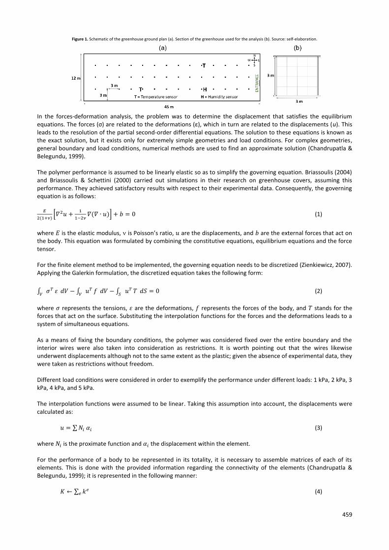
Material White extruded LDPE film sheeting, 0.22 mm in thickness, was used. The degradation of this polymer under field conditions was simulated by applying treatments every two weeks with chemical substances used as pesticides on greenhouse crops, such as permitrine and metham sodium. The test was carried out in a greenhouse located in Almería (south-east Spain). The greenhouse has a 3 m-high flat roof with an east-west longitudinal orientation. The interior supports (posts and cross members) are made of galvanized steel, 3.25 cm in diameter and 3 m apart. The overall dimensions of the greenhouse are 45 x 12 m, with a total surface area of 540 m2; as depicted in Figure 1a.
Numerical simulation of the mechanical performance For the numerical simulation, the finite element method was used (Chapra & Canale, 2007). Only one section of the complete geometry was taken into account, due to the high cost of computing the complete greenhouse. This section is presented in Figure 1b. The profiles of the structure are shown together with the interior wind-protection wire framework.
459
Figure 1. Schematic of the greenhouse ground plan (a). Section of the greenhouse used for the analysis (b). Source: self-elaboration.
In the forces-deformation analysis, the problem was to determine the displacement that satisfies the equilibrium equations. The forces (σ) are related to the deformations (ε), which in turn are related to the displacements (u). This leads to the resolution of the partial second-order differential equations. The solution to these equations is known as the exact solution, but it exists only for extremely simple geometries and load conditions. For complex geometries, general boundary and load conditions, numerical methods are used to find an approximate solution (Chandrupatla & Belegundu, 1999). The polymer performance is assumed to be linearly elastic so as to simplify the governing equation. Briassoulis (2004) and Briassoulis & Schettini (2000) carried out simulations in their research on greenhouse covers, assuming this performance. They achieved satisfactory results with respect to their experimental data. Consequently, the governing equation is as follows:
𝐸
2(1+𝜈)[𝛻2𝑢 +
1
1−2𝜈𝛻(𝛻 ∙ 𝑢)] + 𝑏 = 0
(1)
where 𝐸 is the elastic modulus, is Poisson’s ratio, 𝑢 are the displacements, and 𝑏 are the external forces that act on the body. This equation was formulated by combining the constitutive equations, equilibrium equations and the force tensor. For the finite element method to be implemented, the governing equation needs to be discretized (Zienkiewicz, 2007). Applying the Galerkin formulation, the discretized equation takes the following form:
∫ 𝜎𝑇𝑉
𝜀 𝑑𝑉 − ∫ 𝑢𝑇𝑉
𝑓 𝑑𝑉 − ∫ 𝑢𝑇𝑆
𝑇 𝑑𝑆 = 0
(2)
where 𝜎 represents the tensions, 𝜀 are the deformations, 𝑓 represents the forces of the body, and 𝑇 stands for the forces that act on the surface. Substituting the interpolation functions for the forces and the deformations leads to a system of simultaneous equations. As a means of fixing the boundary conditions, the polymer was considered fixed over the entire boundary and the interior wires were also taken into consideration as restrictions. It is worth pointing out that the wires likewise underwent displacements although not to the same extent as the plastic; given the absence of experimental data, they were taken as restrictions without freedom. Different load conditions were considered in order to exemplify the performance under different loads: 1 kPa, 2 kPa, 3 kPa, 4 kPa, and 5 kPa. The interpolation functions were assumed to be linear. Taking this assumption into account, the displacements were calculated as:
𝑢 = ∑ 𝑁𝑖 𝛼𝑖
(3) where 𝑁𝑖 is the proximate function and 𝛼𝑖 the displacement within the element. For the performance of a body to be represented in its totality, it is necessary to assemble matrices of each of its elements. This is done with the provided information regarding the connectivity of the elements (Chandrupatla & Belegundu, 1999); it is represented in the following manner:
𝐾 ← ∑ 𝑘𝑒𝑒
(4)

460
where K is the matrix of global stiffness of the body and ke is the stiffness matrix of the element. Similarly, the global load vector must be assembled:
𝐹 ← ∑ 𝑓𝑒𝑒
(5) where F represents the global load vector and f e is the force vector of each element.
Results and discussion The loads action was simulated taking into account the properties of the new polymer together with another simulation that considered a used polymer affected by material exposure. Figure 2a shows the results of the displacements, simulated with a 5 kPa load, reflecting that the maximum displacements occurred in the central sections of the wire framework. The comparison between the new and the used polymers revealed minor displacement in the latter due to elasticity loss caused by crystallization after UV-exposure. The results for the corresponding stress appear in Figure 2b. They show that the greatest stresses were at the ends, where there were restrictions of movement and, therefore, greater reactions when the stresses were compared. This occurred to a greater extent in the new polymer since the stresses depended on the displacements and, as mentioned above, these were greater in the new polymer.
Figure 2. Displacements resulting from a 5 kPa load simulation, for both the new and the used polymers (a). Results of the stress
found in the new and the used polymers (b). Source: self-elaboration.
(a)
(b)

461
Because of the boundary conditions, it is of particular interest to determine the displacement values in the centre of the sections (formed by the wire framework) since we expected these areas to present the maximum displacements. Figure 3a shows the displacement values in each area. The new polymer is compared with the old one for different loads. One can see that the maximum displacements occurred in the central region. We found that the same pattern continued both in the new and the used polymers. This is explained because the displacement pattern depends on the geometry, not on the nature of the sample material. The stresses were investigated in the same area. In addition, marks of yield stress point of the new and the used polymers were incorporated for comparison. The stresses in the central area are shown in Figure 3b. One can observe that the greatest stresses occurred where the polymer met the structure; i.e. at heights of 0 and 3 m. Nevertheless, the wire framework area also shows stress concentrations, and there are yield stress point marks. We found that, in the central area, both the new and the old polymers worked in the elastic zone under light-load conditions. In general, the working conditions of the polymer were in the upper zone at the yield stress point; i.e. in the plastic zone.
Figure 3. Displacements in the central section of the wire framework for the new polymer (NP) and the used polymer (UP) (a). Stresses in the central part of the wire framework for the new polymer and the used polymer (b). Source: self-
elaboration.
(a)
(b)

462
For a better visualization of the section values, Figure 4a presents the maximum displacement values according to the different load conditions. It should be noted that these varied linearly due to the loads. Figure 4b shows the maximum stresses that, like the displacements, varied linearly because of the loads. With regard to the breaking stress marks, it can be pointed out that the new polymer failed to reach this stress whereas the used polymer surpassed it with loads greater than 3 kPa; that is to say, the polymer would break under loads greater than this value.
Figure 4. Maximum displacement in the central area of the wire framework under the different load conditions (a). Maximum stresses in the central area of the wire framework under the different loads (b). Source: self-elaboration.
(a)
(b)
In contrast to the displacements, the greatest stresses were not found in the centre but in the lateral areas, where movement was restricted. Therefore, we evaluated the stresses in this area. It is worth mentioning that the displacements were not evaluated in this area since they registered a zero value for the restrictions. Figure 5a shows the stress values where these values were highest. In this zone, the polymer surpassed the yield stress point in most places with lighter loads; highlighting that the cover’s plastic zone was the area of greatest work. The maximum stresses in the lateral area appear in Figure 5b, which includes the marks for the breaking stress. Moreover, it was found that the new polymer was also vulnerable to breaking under the maximum loads in the lateral zone; likewise, the used polymer resisted lesser loads than in the central area. It was therefore expected that in this area, the polymer would generally break.

463
Figure 5. Stresses in the lateral area at different heights (a). Maximum stress in the lateral area under different load conditions (b). Source: self-elaboration.
(a)
(b)
Conclusions Numerical simulations can adequately represent the performance of greenhouse covers using LDPE, provided that the proper considerations are made. This study demonstrated that the pre-used LDPE was no longer in sufficiently good condition for use as a greenhouse cover film due to the degeneration of its mechanical properties. Similarly, it was shown that the general performance of the cover film was in the material’s plastic zone. Therefore, the initial linearity considerations offered only limited results since the plastic zone needs to be considered if more general results are sought; consequently, the performance is nonlinear. Nonetheless, the comparative results are very useful in illustrating the failure process in greenhouse covers caused by their degradation. Further work is in progress to study this material in greater detail under different load conditions.

464
References
ASTM D882 (1991). Standard test method for tensile properties of thin plastic sheeting. American Society for Testing and Materials. ASTM International. United States.
Briassoulis, D. (2004). Mechanical design requirements for low tunnel biodegradable and conventional films. Biosystems Engineering, 87(2), 209-223.
Briassoulis D. & Aristopoulou, A. (2001). Adaptation and harmonisation of standard testing methods for mechanical properties of low-density polyethylene (LDPE) films. Polymer Testing, 20(6), 615-634.
Briassoulis, D., Aristopoulou, A., & Vitali, M. (2000). Adaptation and harmonisation of standard testing methods for mechanical properties of low density polyethylene (LDPE) films. Paper 00- FB-007 presented at AgEng 2000 Conference, Warwick, U. K.
Briassoulis, D. & Schettini, E. (2000). Modelling the mechanical behaviour of greenhouse LDPE film using the finite element method. Paper 00-FB-038 presented at AgEng 2000 Conference, Warwick, U. K.
Briassoulis, D., Waaijenberg, D., Gratraud, J., & von Elsner, B. (1997). Mechanical properties of covering materials for greenhouses, part 1: general overview. Journal of Agricultural Engineering Research, 67, 81–96.
Chandrupatla, T.R. & Belegundu, A.D. (1999). Introducción al estudio del elemento finito en ingeniería. Prentice Hall Hispanoamericana. México.
Chapra, S. & Canale, R. (2007). Métodos numéricos para ingenieros. McGraw-Hill Interamericana. México.
Dilara, P.A. & Briassoulis, D. (1998). Standard testing methods for mechanical properties and degradation of low density polyethylene (LDPE) films used as greenhouse covering materials: a critical evaluation. Polymer Testing, 17, 549-585.
Fragos, V.P., Psychoudaki, S.P., & Malamataris, N.A. (1997). Computer-aided analysis of flow past a surface-mounted obstacle. International Journal for Numerical Methods in Fluids, 25(5), 495-512.
ISO 527-3: 1995. Plastics --Determination of tensile properties-- Part 3: Test conditions for films and sheets. International Organization for Standardization.
Mistriotis, A. & Briassoulis, D. (2002). Numerical estimation of the internal and external aerodynamic coefficients of a tunnel greenhouse structure with openings. Computers and Electronics in Agriculture, 34(1), 191-205.
Reichrath, S. & Davies, T.W. (2002). Computational fluid dynamics simulations and validation of the pressure distribution on the roof of a commercial multi-span Venlo-type glasshouse. Journal of Wind Engineering and Industrial Aerodynamics, 90(3), 139-149.
Shklyar, A. & Arbel, A. (2004). Numerical model of the three-dimensional isothermal flow patterns and mass fluxes in a pitched-roof greenhouse. Journal of Wind Engineering and Industrial Aerodynamics, 92(12), 1039-1059.
Tieleman, H.W. (2003). Wind tunnel simulation of wind loading on low-rise structures: a review. Journal of Wind Engineering and Industrial Aerodynamics, 91(12), 1627-1649.
Wald, M.J., Considine, J.M., & Turner, K.T. (2013). Determining the elastic modulus of compliant thin films supported on substrates from flat punch indentation measurements. Experimental Mechanics, 53, 931-941.
Zienkiewicz, O.M. (2007). El método de los elementos finitos. Editorial Reverté. España.