Embed Size (px)
Citation preview

11th World Congress on Computational Mechanics (WCCM XI)5th European Conference on Computational Mechanics (ECCM V)
6th European Conference on Computational Fluid Dynamics (ECFD VI)E. Onate, J. Oliver and A. Huerta (Eds)
MODELLING UNDER-EXPANDED JET SCREECH BY ILES
ALESSANDRO MANCINI∗, DANILO DI STEFANO†, EDWARD H. HALL‡
AND ALDO RONA§
Department of Engineering, University of Leicester, LE1 7RH, England∗ e-mail: [email protected], † e-mail: [email protected]‡ e-mail: [email protected], § e-mail: [email protected]
web page: http://www.le.ac.uk/eg/ar45
Key words: Implicit Large Eddy Simulations, Jet, Screech, Numerical Methods.
Abstract. Axisymmetric screech from an under-expanded contoured sonic nozzle is mod-elled by Implicit Large Eddy Simulations (ILES). A self-sustained shear-layer instabilitydevelops naturally, without artificial excitation, in the time-marching ILES simulation.This reproduces some of the main flow characteristics of the A2 axisymmetric screechmode documented in experiment. This includes a tonal pressure field, which is resolvedby the model. The axisymmetric modelling approach prevents the development of az-imuthal structures in the jet shear-layer downstream of the potential core, which areknown to be important features for controlling jet mixing and broad-band jet noise.
1 INTRODUCTION
High-speed fighter aircraft feature low-bypass engines where the dominant noise sourceis the aerodynamic jet noise, which can feature an intense tonal noise, commonly referredto as a screech tone. The origin of screech stems from operating the jet incorrectlyexpanded, whereupon a system of shock cells interacts with convected instabilities in thejet outer shear-layer, generating noise [1].
The selection of convectively amplifying shear-layer instabilities by upstream feed-back locks the noise generation process in a feed-back loop, which determines the tonalcharacteristic of screech. From a computational viewpoint, screech therefore involvesmainly a narrow band of the kinetic energy spectrum in the jet shear layer. This makesthe problem treatable by a numerical approach that resolves directly the relevant scalesof motion associated to screech and models the effects of any under-resolved smaller-scaledynamics on the resolved motion. Such an approach has been followed in the form of anImplicit Large Eddy Simulation (ILES).
Jet screech can feature a combination of axisymmetric modes, commonly denoted asA modes, and of spiral modes, or B modes, depending on the degree of incorrect expan-sion [2]. The most acoustically active source region in an incorrectly expanded jet stretches
1

Alessandro Mancini, Danilo Di Stefano, Edward H. Hall and Aldo Rona
from the proximity of the nozzle lip, where the high-frequency contribution mainly orig-inates from the interaction of small amplitude shear-layer disturbances with the intenseshocks and expansion waves, to the end of the jet potential core, where the shear-layerinstabilities, which have grown to finite amplitude, interact with the weaker shock-cellsystem. The shock-cell spacing close to the nozzle exit plane is mainly determined bythe inviscid compressible momentum-energy balance and is progressively affected by thegrowth rate of the jet shear layer at increasing axial distances.
Incorrectly expanded jets from nozzles operating close to their design Mach numbers,such as Mach 1 for convergent nozzles, exhibit an axisymmentric instability mode [3],leading to an axisymmetric screech noise pattern, when screech is present. At these con-ditions, a time-resolved simulation of the shock cells enclosed in the thin shear-layer in theearly stages of streamwise growth, close to the nozzle lip, is expected to be able to capturethe main mechanisms responsible for the generation of screech. This approach is imple-mented by performing an axisymmetric Implicit Large Eddy Simulation of an incorrectlyexpanded jet. The absence of the azimuthal degree of freedom in the computation limitsthe growth of secondary, spiral mode instabilities in the shear-layer. As a consequence,the shear-layer is expected to exhibit a reduced growth rate downstream of the end of thepotential core.
The aim of this research is to explore the use of axisymmetric Implicit Large Eddy Sim-ulations as a lower computational cost technique, compared to three-dimensional LargeEddy Simulations, for modelling the compressible flow dynamics of a screeching jet close tothe nozzle exit and for predicting the dominant narrow-band components of the radiatingunsteady pressure near-field.
2 FLOW CONDITIONS
Axisymmetic Implicit Large Eddy Simulations are obtained for a contoured convergentnozzle designed for parallel flow at exit. The nozzle design exit Mach number Me is 1.0.The simulation is designed to match the geometry and the experimental flow conditionstested by Andre [4]. At the nozzle exit plane, the inner nozzle diameter is 38 mm and thenozzle lip is 0.5 mm thick. The nozzle is supplied with unheated air at a nozzle pressureratio of 2.27, corresponding to a fully expanded isentropic exit Mach number Mj = 1.15.Over a range of nozzle operating conditions, experiments found the turbulence intensityat the nozzle exit plane to be about 2% [4]. The jet discharges in ambient quiescent airat pressure pa = 98 kPa and temperature Ta = 288.15 K. The Reynolds number based onthe nozzle exit diameter and flow conditions is 1.2× 10⁶. The air flow is modelled underconstant specific heat ideal gas assumptions, with the specific gas constant R = 287.058J/(kg K) and the specific heat ratio γ = 1.4.
2
Alessandro Mancini, Danilo Di Stefano, Edward H. Hall and Aldo Rona
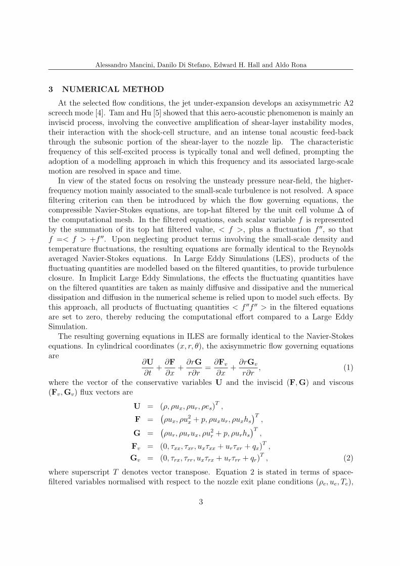
3 NUMERICAL METHOD
At the selected flow conditions, the jet under-expansion develops an axisymmetric A2screech mode [4]. Tam and Hu [5] showed that this aero-acoustic phenomenon is mainly aninviscid process, involving the convective amplification of shear-layer instability modes,their interaction with the shock-cell structure, and an intense tonal acoustic feed-backthrough the subsonic portion of the shear-layer to the nozzle lip. The characteristicfrequency of this self-excited process is typically tonal and well defined, prompting theadoption of a modelling approach in which this frequency and its associated large-scalemotion are resolved in space and time.
In view of the stated focus on resolving the unsteady pressure near-field, the higher-frequency motion mainly associated to the small-scale turbulence is not resolved. A spacefiltering criterion can then be introduced by which the flow governing equations, thecompressible Navier-Stokes equations, are top-hat filtered by the unit cell volume ∆ ofthe computational mesh. In the filtered equations, each scalar variable f is representedby the summation of its top hat filtered value, < f >, plus a fluctuation f ′′, so thatf =< f > +f ′′. Upon neglecting product terms involving the small-scale density andtemperature fluctuations, the resulting equations are formally identical to the Reynoldsaveraged Navier-Stokes equations. In Large Eddy Simulations (LES), products of thefluctuating quantities are modelled based on the filtered quantities, to provide turbulenceclosure. In Implicit Large Eddy Simulations, the effects the fluctuating quantities haveon the filtered quantities are taken as mainly diffusive and dissipative and the numericaldissipation and diffusion in the numerical scheme is relied upon to model such effects. Bythis approach, all products of fluctuating quantities < f ′′f ′′ > in the filtered equationsare set to zero, thereby reducing the computational effort compared to a Large EddySimulation.
The resulting governing equations in ILES are formally identical to the Navier-Stokesequations. In cylindrical coordinates (x, r, θ), the axisymmetric flow governing equationsare
∂U
∂t+
∂F
∂x+
∂rG
r∂r=
∂Fv
∂x+
∂rGv
r∂r, (1)
where the vector of the conservative variables U and the inviscid (F,G) and viscous(Fv,Gv) flux vectors are
U = (ρ, ρux, ρur, ρes)T ,
F =(ρux, ρu
2x + p, ρuxur, ρuxhs
)T,
G =(ρur, ρurux, ρu
2r + p, ρurhs
)T,
Fv = (0, τxx, τxr, uxτxx + urτxr + qx)T ,
Gv = (0, τrx, τrr, uxτrx + urτrr + qr)T , (2)
where superscript T denotes vector transpose. Equation 2 is stated in terms of space-filtered variables normalised with respect to the nozzle exit plane conditions (ρe, ue, Te),
3
Alessandro Mancini, Danilo Di Stefano, Edward H. Hall and Aldo Rona
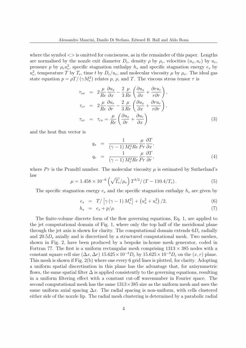
where the symbol<> is omitted for conciseness, as in the remainder of this paper. Lengthsare normalised by the nozzle exit diameter De, density ρ by ρe, velocities (ux, ur) by ue,pressure p by ρeu
2e, specific stagnation enthalpy hs and specific stagnation energy es by
u2e, temperature T by Te, time t by De/ue, and molecular viscosity µ by µe. The ideal gas
state equation p = ρT/ (γM2e ) relates p, ρ, and T . The viscous stress tensor τ is
τxx = 2µ
Re
∂ux
∂x− 2
3
µ
Re
(∂ux
∂x+
∂rur
r∂r
),
τrr = 2µ
Re
∂ur
∂r− 2
3
µ
Re
(∂ux
∂x+
∂rur
r∂r
),
τxr = τrx =µ
Re
(∂ux
∂r+
∂ur
∂x
)(3)
and the heat flux vector is
qx =1
(γ − 1)M2eRe
µ
Pr
∂T
∂x,
qr =1
(γ − 1)M2eRe
µ
Pr
∂T
∂r, (4)
where Pr is the Prandtl number. The molecular viscosity µ is estimated by Sutherland’slaw
µ = 1.458× 10⁻⁶(√
Te/µe
)T 3/2/ (T − 110.4/Te) . (5)
The specific stagnation energy es and the specific stagnation enthalpy hs are given by
es = T/[γ (γ − 1)M2
e
]+(u2x + u2
r
)/2, (6)
hs = es + p/ρ. (7)
The finite-volume discrete form of the flow governing equations, Eq. 1, are applied tothe jet computational domain of Fig. 1, where only the top half of the meridional planethrough the jet axis is shown for clarity. The computational domain extends 6De radiallyand 20.5De axially and is discretised by a structured computational mesh. Two meshes,shown in Fig. 2, have been produced by a bespoke in-house mesh generator, coded inFortran 77. The first is a uniform rectangular mesh comprising 1313× 385 nodes with aconstant square cell size (∆x,∆r) 15.625×10−3De by 15.625×10−3De on the (x, r) plane.This mesh is shown if Fig. 2(b) where one every 6 grid lines is plotted, for clarity. Adoptinga uniform spatial discretisation in this plane has the advantage that, for axisymmetricflows, the same spatial filter ∆ is applied consistently to the governing equations, resultingin a uniform filtering effect with a constant cut-off wavenumber in Fourier space. Thesecond computational mesh has the same 1313×385 size as the uniform mesh and uses thesame uniform axial spacing ∆x. The radial spacing is non-uniform, with cells clusteredeither side of the nozzle lip. The radial mesh clustering is determined by a parabolic radial
4

Alessandro Mancini, Danilo Di Stefano, Edward H. Hall and Aldo Rona
t
6D b4 (extrapolated)
b5−b7 (inviscid wall)
b3 (extrapolated)
b1 (symmetric)
b2 (extrapolated)
x
r
D
ue
e
ee
20.5De
Figure 1: Computational domain and boundary conditions.
size distribution function with the minimum ∆r = 2.63 × 10⁻³De located at the nozzlelip radius. The resulting mesh is shown in Fig. 2(a), where one every 6 grid lines in xand r is plotted, for clarity. This mesh non-uniformity in r enables a greater local spatialresolution close to the nozzle lip, where the shear-layer is radially thin, and reduces thecomputational resources required away from the jet axis, where long-wavelength acousticwaves are expected to radiate in the ambient flow.
On the radially stretched mesh, the nozzle internal diameter De and the nozzle lipthickness te have the same size as in experiment [4] at the nozzle exit plane. On theuniform mesh, the nozzle internal diameter De at the nozzle exit plane matches theexperiment but the nozzle lip is thicker than in experiment.
The jet flow is characterised by compressible features, such as shocks, expansion fans,and regions of significant flow shear. These features produce significant localised gradientsin the conservative variables. To resolve these features, a time-marching Total VariationDiminishing (TVD) scheme is used to integrate the space-filtered flow governing equationsin finite-volume form. The inviscid fluxes at the computational cell interfaces are evaluatedusing the second-order form of the Roe [6, 7] flux difference approximate Riemann solverin the interface-normal direction. Numerical stability is provided by applying the min-mod flux limiter. Second-order central differences are used to evaluate the viscous fluxesat the cell interfaces.
The computation is time-marched by a two-step Runge-Kutta scheme implemented inthe low storage form of Hu et al. [8]. The standard Runge-Kutta coefficients (1.0, 0.5) areused. A further description of this numerical integration procedure can be found in Ronaand Zhang [9].
Along the perimeter of the computational domain, boundary conditions are imposed as
5

Alessandro Mancini, Danilo Di Stefano, Edward H. Hall and Aldo Rona
0 5 10 15 206
4
2
0
2
4
6
(a)
r
x
(b)
u e
Figure 2: (a) Radially stretched computational mesh, (b) Uniform computational mesh.
shown in Fig. 1. A reflecting boundary b1 is imposed along the jet axis where Ui,−j = U∗i,j
for j = 1 and j = 2, where r = j∆r and U∗ = (ρ, ρux − ρux∆i, ρur − ρur∆j, ρes)T . The
open flow boundaries b2-b4 are treated by a linear extrapolation of flow state from thecomputational domain interior. The solid boundaries b5-b7 are modelled by the wallcondition rUi,−j = rU∗
i,j for j = 1 and j = 2 and U−i,j = U∗i,j for i = 1 and i = 2 for the
horizontal and vertical surfaces, respectively. At the nozzle inlet, a constant flow state(ρe, ue, Te,Me) is imposed throughout the computation.
At the start of the computation, the computational domain outside the nozzle is primedwith the ambient zero flow conditions and the jet is impulsively started by the nozzle inletsupersonic inflow. This abrupt start condition challenges the computational stability ofthe scheme, as it generates a downstream propagating bow shock outside the nozzle. Theflow was therefore uniformly time-marched by a variable time step corresponding to amaximum Courant number of 0.8. The variable time step is evaluated at every iterationas the maximum non-dimensional ∆t that gives the target Courant number, based onthe local computational cell geometry and the local flow conditions. The computationson the uniform and stretched meshes were time-marched to the non-dimensional timest = 15.5/De and t = 3.39/De, respectively, to obtain a stationary flow, as indicated bythe static pressure monitored at x = 1.5De on the jet axis and along the nozzle lip line.By t = 1/De, the bow shock has propagated through the downstream boundary b2 ofFig. 1 and a jet with an organised shock-cell pattern is developed.
6

Alessandro Mancini, Danilo Di Stefano, Edward H. Hall and Aldo Rona
During this initial transient, an axisymmetric self-sustained shear-layer instability de-veloped in the axisymmetric flow without forcing. The jet self-selected its shear-layermode frequency f and Strouhal number Str = fDe/ue. Fourier analysis of the monitoredstatic pressure on the uniform mesh simulation indicated two spectral peaks, with the low-est (fundamental) screech Strouhal number Str = 0.6958. The combination of the removalof the strong bow shock by its propagation through the computational boundaries andthe stabilising effect of the viscous dissipation allowed the computation to time-advanceat larger variable time-steps, compared to when the bow shock was present, still keepingthe constant Courant number of 0.8.
After the flow has settled into a self-sustained shear-layer fluctuation flow regime,characterised by a substantially time-invariant fundamental screech frequency, the time-averaged flow field was obtained from the time-dependent computation as a running av-erage of the primitive variables (ρ, ux, ur, p). On the uniform mesh, the running averagewas obtained between the non-dimensional times of t = 15.5/De and t = 17.15/De, corre-sponding to 30 periods T = 1/f of the measured screech mode frequency f = 5841 Hz [4].Root-mean-square averages of the primitive variables were obtained alongside the meanvalues. On the radially stretched mesh, a longer running average between non-dimensionaltimes of t = 3.39/De and t = 6.25/De was used.
4 RESULTS
4.1 Time-averaged flow predictions compared to experiment
Figure 3 shows the Mach number distribution, referenced to the local speed of soundc, along the jet axis. The numerical prediction from the uniform mesh, shown by the con-tinuous line, is compared with measurements by Andre [4], denoted by (◦). The locationand amplitude of the Prandtl-Mayer expansion fan at nozzle lip and the subsequent con-ical shock appear to be predicted well by just using an axisymmetric ILES computation.This is shown by the good match in axial location and value, between experiment andprediction, of the low Mach number at the nozzle exit, the sharp first static Mach num-ber peak, and the subsequent Mach number minimum. Further downstream, while thespacing between subsequent Mach number maxima and minima is in broad agreement,the amplitude of the streamwise Mach number fluctuations is lower in the predictionscompared to the experiment. This is likely to result from the axial precession of theshock cells, due to the shear-layer motion. The movement of the shock-cells during therunning average causes shock smearing in the time-averaged flow, reducing the amplitudeof the extrema in the axial Mach number distribution. As the shear-layer motion growsin amplitude with increasing downstream distance from the nozzle exit plane, the shockcells further away from the nozzle exit are more affected by this shock smearing processin the time-averaged flow, as indicated in Fig. 3. The same trend is displayed by thetime-averaged Mach number distribution predicted by the radially stretched ILES.
Table 1 shows the comparison between the shock cell lengths predicted by the ILES
7

Alessandro Mancini, Danilo Di Stefano, Edward H. Hall and Aldo Rona
x/De
M
0 2 4 6 8
1
1.1
1.2
1.3
1.4
Figure 3: Mach number distribution along the jet axis. (−) ILES uniform mesh flow prediction averagedover 30T , (− · −) ILES radially stretched mesh prediction averaged over 50T , (◦) experiment [4].
using the uniform mesh and the ones reported in the measurements [4]. Both measure-ments and predictions indicate a monotonic reduction in shock cell length with axialdistance. The shear layer grows in the downstream direction by entrainment of the lowspeed flow that surrounds it. Axial momentum transfer to the entrained fluid from thehigh-speed flow closer to the jet axis reduces the enclosed high-speed flow radius. Theboundary between the shear layer and the high-speed flow is therefore convex and theaxial velocity progressively reduces, due to the irreversible axial momentum loss throughthe shocks. This results in progressively more normal compression and expansion waves,which reduce the shock cell spacing in the axial direction. The predicted shock spacingis in broad agreement with experiment over the first three shock cells. Figure 3 indicatesthat the agreement in shock-cell length progressively decreases with increasing shock cellnumber. The shear layer thickness is smaller over the first three shock cells, increasingmonotonically in the positive axial direction. As the time-averaged shear layer thicknessis determined by the diffusive and dissipative effects in the flow momentum and, in theImplicit Large Eddy Simulation, these effects are numerical scheme dependent, furtherimprovements in the numerical mesh and in the limiter function are likely to improve thecurrent flow predictions.
Figure 4 shows the non-dimensional time-averaged density contours from the radiallystretched ILES, Fig. 4(a), and from the uniform mesh ILES, Fig. 4(b). The pattern ofalternating shock-cells close to the nozzle lip is shown in both simulations. The intensity
8

Alessandro Mancini, Danilo Di Stefano, Edward H. Hall and Aldo Rona
Table 1: Axial length of shock cells.
Shock spacing ILES uniform mesh ILES stretched mesh Measurement [4]L1/De 0.72 0.72 0.73L2/De 0.73 0.69 0.68L3/De 0.69 0.73 0.68Lavg/De 0.71 0.71 0.70
Figure 4: Non-dimensional time-averaged density contours. (a) radially stretched mesh ILES, (b)uniform mesh ILES. ρmin = 0.66ρe, ρmax = 1.03ρe, ∆ρ = 0.03ρe.
of the shocks and expansions are shown to decrease with increasing axial distance fromthe nozzle exit plane. The waviness of the contours furthest from the jet axis suggest thatthe running average time may have been insufficient for producing a time-independentstatistically converged mean flow. This feature is more evident in Fig. 4(b), where themean field is estimated over the shorter non-dimensional averaging time ∆t = 1.65/De.
4.2 Time-resolved flow predictions
Time-resolved flow predictions are obtained from both the uniform mesh simulation andfrom the radially stretched mesh simulation. The non-dimensional aerodynamic pressuremonitored on the jet axis in Fig. 5(a) is unsteady, displaying fluctuations that have arich yet narrow-band spectral content, as suggested by the presence of about 30 smoothpressure peaks over the non-dimensional sampling time of 1.65/De. The Discrete FourierTransform of the digital pressure history, shown in Fig. 5(b), confirms that the near-fieldaerodynamic pressure is characterised by one well-defined spectral peak. This compares totwo spectral peaks identified in experiment [4] at 5171 Hz and 5841 Hz, corresponding toStr = 0.617 and 0.697. The dominant Strouhal number tone from the current simulationis 0.6958. A spectrogram analysis reported by Andre suggests that the modes associated to
9

Alessandro Mancini, Danilo Di Stefano, Edward H. Hall and Aldo Rona
15.5 16 16.5 17
0.64
0.66
0.68
0.7
tDe
p/(
ρeu2 e
)
(a) Non-dimensional pressure history.
0 0.5 1 1.5 20
0.005
0.01
0.015
0.02
Str
|P(S
tr)|
(b) Non-dimensional pressure spectrum.
Figure 5: Pressure at (x, r) = (1.5De, 0) from the uniform mesh ILES.
these screech frequencies alternate over time and a similar mechanism has been observedby a similar spectrogram analysis of the numerical predictions from the uniform meshILES.
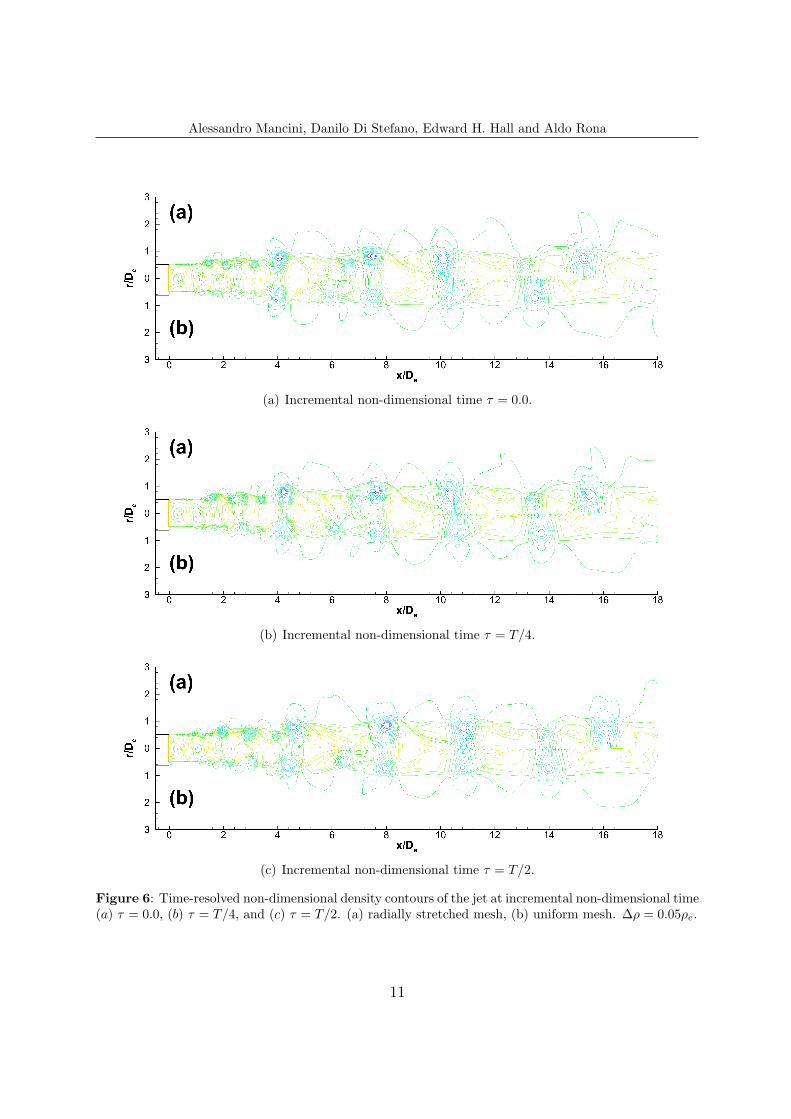
Time-resolved density snapshots of the under-expanded jet are reported in Fig. 6,covering three successive phases of the period T associated to the fundamental screech toneidentified in the pressure spectrum of each ILES simulation. In both the uniform mesh andradially stretched mesh results, an intense shear-layer flow dynamics is predicted. This ischaracterised by the roll-up of toroidal vortices downstream of the nozzle lip line that growin the streamwise direction as they are pushed by the core jet towards the downstreamcomputational domain boundary. The passage of the vortices through the shock cellsaffect the position of the pressure waves that precess over time about their time-averagedposition, confirming the inference of the ’shock smearing’ effect in the time-averaged axialMach number distribution from Fig. 3.
5 CONCLUSIONS
Axisymmetric Implicit Large Eddy Simulations are used as a reduced cost computa-tional model for predicting the narrow-band tonal flow dynamics of an under-expandedjet in screech. The model restricts the resolved instability modes in the jet to axisymmet-ric (varicose) shear-layer instabilities that interact with the shock-cell pattern, producinglarge-amplitude near-field pressure fluctuations. The mainly inviscid nature of screech,which mainly involves the shock cells in the neighbourhood of the nozzle outlet, enablesthe use of such a reduced model that does not resolve the complex three-dimensionalflow mixing characterizing the jet plume further downstream. Predictions of unsteadypressure and of time-averaged Mach number in broad qualitative agreement with theavailable experimental data indicate that, within limits, the axisymmetric simulation isa useful model for exploring the motion of the shear-layer and its interaction with theshock-cell structure.
10
Alessandro Mancini, Danilo Di Stefano, Edward H. Hall and Aldo Rona
(a) Incremental non-dimensional time τ = 0.0.
(b) Incremental non-dimensional time τ = T/4.
(c) Incremental non-dimensional time τ = T/2.
Figure 6: Time-resolved non-dimensional density contours of the jet at incremental non-dimensional time(a) τ = 0.0, (b) τ = T/4, and (c) τ = T/2. (a) radially stretched mesh, (b) uniform mesh. ∆ρ = 0.05ρe.
11

Alessandro Mancini, Danilo Di Stefano, Edward H. Hall and Aldo Rona
6 ACKNOWLEDGEMENT
This work has received support from the European Union Seventh Framework Pro-gramme FP7/2007-2013 under grant agreement no. 317142. This paper has used dig-itized experimental data kindly provided by Carlos Perez-Arroyo and Guillaume Puigt,CERFACS, France.
REFERENCES
[1] Harper-Bourne, M. and Fisher, M. The noise from shock waves in supersonic jets.AGARD Conference Proceedings 131, September 1973.
[2] Hubbard, H.H. Aeroacoustics of flight vehicles : theory and practice. NASA ReferencePublication 1258, Woodbury, NY, (1995).
[3] Raman, G. Advances in understanding supersonic jet noise screech: Review andperspective. Prog. Aerospace Sci. (1998) 34:45–106.
[4] Andre, B. Etude experimentale de l’effet du vol sur le bruit de choc de jets superson-iques sous-detendus. PhD, Ecole Centrale de Lyon, France, (2012).
[5] Tam, C. and Hu, F. On the three families of instability waves of high-speed jets.Journal of Fluid Mechanics (1989) 201:447–483.
[6] Roe, P. Approximate Riemann solvers, parameter vectors and difference schemes.Journal of Computational Physics (1981) 43:357–372.
[7] Roe, P. Characteristics-based schemes for the Euler equations. Annual Review ofFluid Mechanics (1986) 18:337–365.
[8] Hu, F., Hussaini, M., and Manthey, J. Application of low dissipation and dis-persion Runge-Kutta schemes to benchmark problems in computational aeroacous-tics. ICASE/LaRC workshop on benchmark problems in computational aeroacoustics(CAA), NASA Conference Publication 3300, (1995) 73–98.
[9] Rona, A. and Zhang, X. Time accurate numerical study of turbulent supersonic jets.Journal of Sound and Vibration (2004) 270:297–321.
12