Embed Size (px)
Citation preview

The henry Tool Co., ManufaCTured by henry Tools498 so. belvoir blvd., souTh euClid, oh 44121 u.s.a.
Ph: (216) 291-1011 or (800) 826-5257 ● Fax: (216) 291-5949 or (800) 303-2800Email: [email protected] ● WEbsitE: WWW.hEnrytools.com
General Safety and Maintenance Manual
MODELS49 RA49 RAZ49 RAC
ModelNumber
Exhaust Direction
ThrottleType
Speed PowerOutput
CaseMaterial
WeightLength Diameter Air
ConsumptionSpindle ThreadAluminum
49 RA
REAR
(L) Leveror(K) SafetyLever
12000to 14000R.P.M (13500rpm is standard)
0.9 H.P.(675 W)
Alumi-num
2 1/2 lbs1.1kg
8 5/16”-211mm
1 3/4”4.4cm
25 CFM(11.8 L/S)
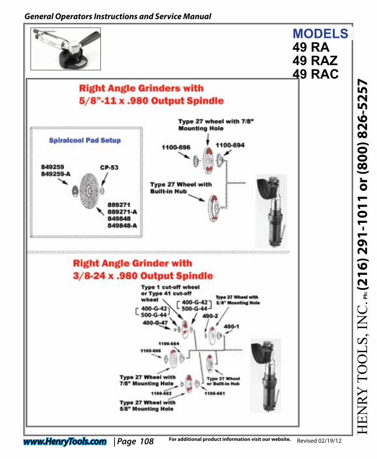
3/8-24 x 0.98 Inch
49 RAZ 5/8-11 x 0.98 Inch (25mm)
49 RAC1/4 Inch Burrs/Mounted Points
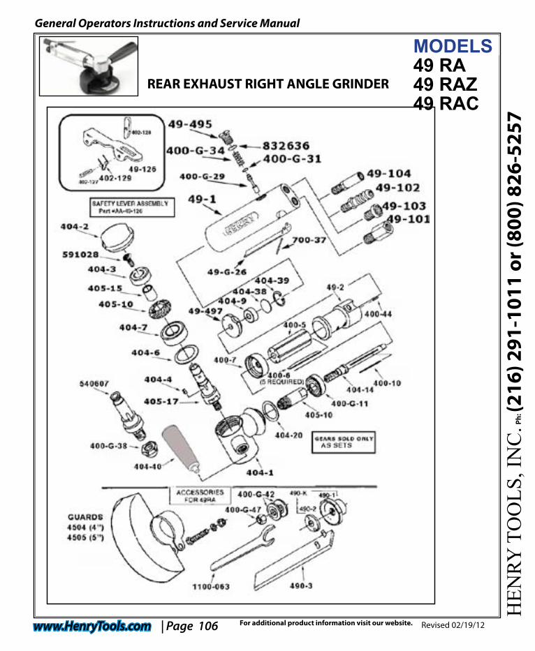
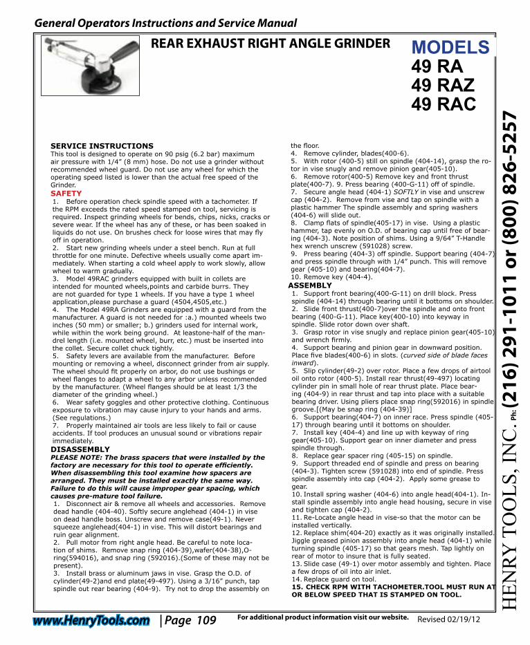
REAR EXHAUST RIGHT ANGLE GRINDER
MODEL 49 RA grinder featuring a rear exhaust.
HEN
RY T
OO
LS, I
NC
. Ph: (2
16) 2
91-1
011
or (8
00) 8
26-5
257
General Operators Instructions and Service Manual
www.HenryTools.com | Page 106 Revised 02/19/12For additional product information visit our website.
MODELS49 RA49 RAZ49 RAC
REAR EXHAUST RIGHT ANGLE GRINDER
HEN
RY T
OO
LS, I
NC
. Ph: (2
16) 2
91-1
011
or (8
00) 8
26-5
257
General Operators Instructions and Service Manual
www.HenryTools.com | Page 107 Revised 02/19/12For additional product information visit our website.
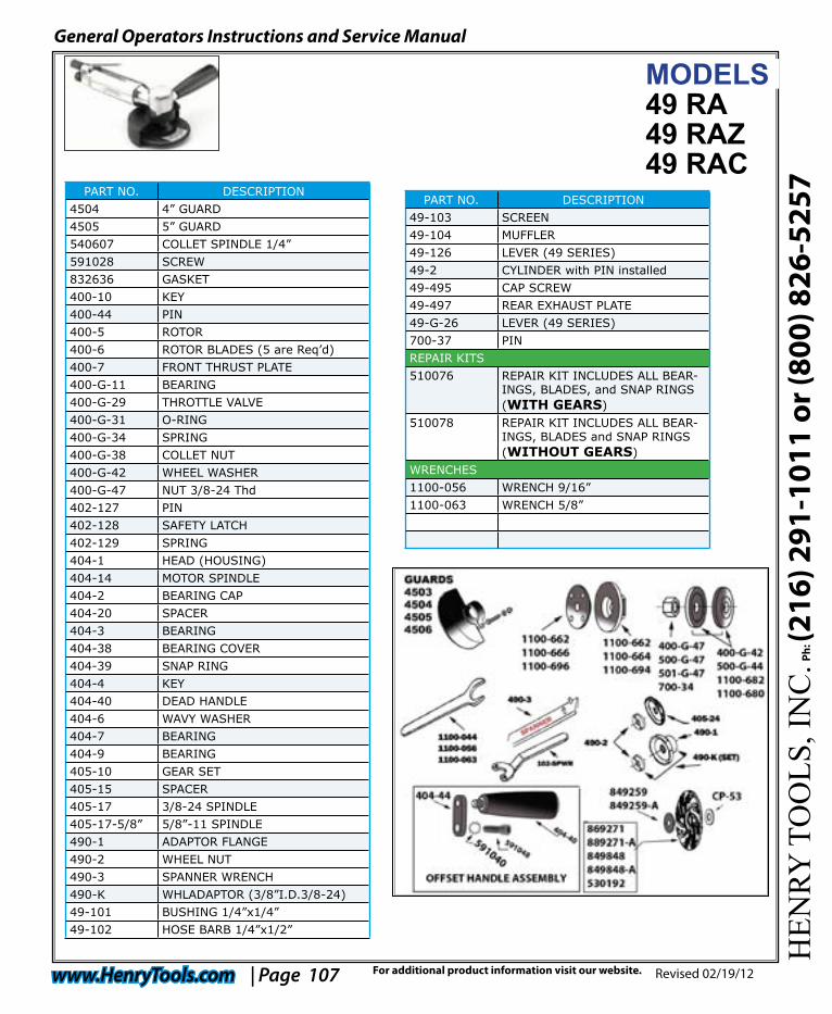
PART NO. DESCRIPTION4504 4” GUARD4505 5” GUARD540607 COLLET SPINDLE 1/4”591028 SCREW832636 GASKET400-10 KEY400-44 PIN400-5 ROTOR 400-6 ROTOR BLADES (5 are Req’d)400-7 FRONT THRUST PLATE400-G-11 BEARING400-G-29 THROTTLE VALVE400-G-31 O-RING400-G-34 SPRING400-G-38 COLLET NUT400-G-42 WHEEL WASHER400-G-47 NUT 3/8-24 Thd402-127 PIN402-128 SAFETY LATCH402-129 SPRING404-1 HEAD (HOUSING)404-14 MOTOR SPINDLE404-2 BEARING CAP404-20 SPACER404-3 BEARING 404-38 BEARING COVER404-39 SNAP RING404-4 KEY404-40 DEAD HANDLE404-6 WAVY WASHER404-7 BEARING404-9 BEARING405-10 GEAR SET405-15 SPACER405-17 3/8-24 SPINDLE405-17-5/8” 5/8”-11 SPINDLE490-1 ADAPTOR FLANGE490-2 WHEEL NUT490-3 SPANNER WRENCH490-K WHLADAPTOR (3/8”I.D.3/8-24)49-101 BUSHING 1/4”x1/4”49-102 HOSE BARB 1/4”x1/2”
PART NO. DESCRIPTION49-103 SCREEN49-104 MUFFLER49-126 LEVER (49 SERIES)49-2 CYLINDER with PIN installed49-495 CAP SCREW49-497 REAR EXHAUST PLATE49-G-26 LEVER (49 SERIES)700-37 PINREPAIR KITS510076 REPAIR KIT INCLUDES ALL BEAR-
INGS, BLADES, and SNAP RINGS (WITH GEARS)
510078 REPAIR KIT INCLUDES ALL BEAR-INGS, BLADES and SNAP RINGS (WITHOUT GEARS)
WRENCHES1100-056 WRENCH 9/16”1100-063 WRENCH 5/8”
MODELS49 RA49 RAZ49 RAC
HEN
RY T
OO
LS, I
NC
. Ph: (2
16) 2
91-1
011
or (8
00) 8
26-5
257
General Operators Instructions and Service Manual
www.HenryTools.com | Page 108 Revised 02/19/12For additional product information visit our website.
MODELS49 RA49 RAZ49 RAC
HEN
RY T
OO
LS, I
NC
. Ph: (2
16) 2
91-1
011
or (8
00) 8
26-5
257
General Operators Instructions and Service Manual
www.HenryTools.com | Page 109 Revised 02/19/12For additional product information visit our website.
SERVICE INSTRUCTIONSThis tool is designed to operate on 90 psig (6.2 bar) maximumair pressure with 1/4” (8 mm) hose. Do not use a grinder without recommended wheel guard. Do not use any wheel for which the operating speed listed is lower than the actual free speed of the Grinder.SAFETY1. Before operation check spindle speed with a tachometer. If the RPM exceeds the rated speed stamped on tool, servicing is required. Inspect grinding wheels for bends, chips, nicks, cracks or severe wear. If the wheel has any of these, or has been soaked in liquids do not use. On brushes check for loose wires that may fly off in operation. 2. Start new grinding wheels under a steel bench. Run at full throttle for one minute. Defective wheels usually come apart im-mediately. When starting a cold wheel apply to work slowly, allow wheel to warm gradually. 3. Model 49RAC grinders equipped with built in collets are intended for mounted wheels,points and carbide burrs. They are not guarded for type 1 wheels. If you have a type 1 wheel application,please purchase a guard (4504,4505,etc.) 4. The Model 49RA Grinders are equipped with a guard from the manufacturer. A guard is not needed for :a.) mounted wheels two inches (50 mm) or smaller; b.) grinders used for internal work, while within the work being ground. At leastone-half of the man-drel length (i.e. mounted wheel, burr, etc.) must be inserted into the collet. Secure collet chuck tightly. 5. Safety levers are available from the manufacturer. Before mounting or removing a wheel, disconnect grinder from air supply. The wheel should fit properly on arbor, do not use bushings or wheel flanges to adapt a wheel to any arbor unless recommended by the manufacturer. (Wheel flanges should be at least 1/3 the diameter of the grinding wheel.) 6. Wear safety goggles and other protective clothing. Continuous exposure to vibration may cause injury to your hands and arms.(See regulations.) 7. Properly maintained air tools are less likely to fail or cause accidents. If tool produces an unusual sound or vibrations repair immediately.DISASSEMBLYPLEASE NOTE: The brass spacers that were installed by the factory are necessary for this tool to operate efficiently. When disassembling this tool examine how spacers are arranged. They must be installed exactly the same way. Failure to do this will cause improper gear spacing, which causes pre-mature tool failure.1. Disconnect air & remove all wheels and accessories. Remove dead handle (404-40). Softly secure anglehead (404-1) in vise on dead handle boss. Unscrew and remove case(49-1). Never squeeze anglehead(404-1) in vise. This will distort bearings and ruin gear alignment.2. Pull motor from right angle head. Be careful to note loca-tion of shims. Remove snap ring (404-39),wafer(404-38),O-ring(594016), and snap ring (592016).(Some of these may not be present).3. Install brass or aluminum jaws in vise. Grasp the O.D. of cylinder(49-2)and end plate(49-497). Using a 3/16” punch, tap spindle out rear bearing (404-9). Try not to drop the assembly on
the floor.4. Remove cylinder, blades(400-6). 5. With rotor (400-5) still on spindle (404-14), grasp the ro-tor in vise snugly and remove pinion gear(405-10).6. Remove rotor(400-5) Remove key and front thrust plate(400-7). 9. Press bearing (400-G-11) off of spindle.7. Secure angle head (404-1) SOFTLY in vise and unscrew cap (404-2). Remove from vise and tap on spindle with a plastic hammer The spindle assembly and spring washers (404-6) will slide out.8. Clamp flats of spindle(405-17) in vise. Using a plastic hammer, tap evenly on O.D. of bearing cap until free of bear-ing (404-3). Note position of shims. Using a 9/64” T-Handle hex wrench unscrew (591028) screw.9. Press bearing (404-3) off spindle. Support bearing (404-7) and press spindle through with 1/4” punch. This will remove gear (405-10) and bearing(404-7).10. Remove key (404-4).
ASSEMBLY1. Support front bearing(400-G-11) on drill block. Press spindle (404-14) through bearing until it bottoms on shoulder.2. Slide front thrust(400-7)over the spindle and onto front bearing (400-G-11). Place key(400-10) into keyway in spindle. Slide rotor down over shaft. 3. Grasp rotor in vise snugly and replace pinion gear(405-10) and wrench firmly. 4. Support bearing and pinion gear in downward position. Place five blades(400-6) in slots. (curved side of blade faces inward).5. Slip cylinder(49-2) over rotor. Place a few drops of airtool oil onto rotor (400-5). Install rear thrust(49-497) locating cylinder pin in small hole of rear thrust plate. Place bear-ing (404-9) in rear thrust and tap into place with a suitable bearing driver. Using pliers place snap ring(592016) in spindle groove.[(May be snap ring (404-39)]6. Support bearing(404-7) on inner race. Press spindle (405-17) through bearing until it bottoms on shoulder. 7. Install key (404-4) and line up with keyway of ring gear(405-10). Support gear on inner diameter and press spindle through.8. Replace gear spacer ring (405-15) on spindle. 9. Support threaded end of spindle and press on bearing (404-3). Tighten screw (591028) into end of spindle. Press spindle assembly into cap (404-2). Apply some grease to gear. 10. Install spring washer (404-6) into angle head(404-1). In-stall spindle assembly into angle head housing, secure in vise and tighten cap (404-2).11. Re-Locate angle head in vise-so that the motor can be installed vertically.12. Replace shim(404-20) exactly as it was originally installed. Jiggle greased pinion assembly into angle head (404-1) while turning spindle (405-17) so that gears mesh. Tap lightly on rear of motor to insure that is fully seated. 13. Slide case (49-1) over motor assembly and tighten. Place a few drops of oil into air inlet.14. Replace guard on tool.15. CHECK RPM WITH TACHOMETER.TOOL MUST RUN AT OR BELOW SPEED THAT IS STAMPED ON TOOL.
MODELS49 RA49 RAZ49 RAC
REAR EXHAUST RIGHT ANGLE GRINDER