Embed Size (px)
Citation preview
MODERN BLIND STICK
SYED HAZIQ AFIF BIN SYED MOHD FAZLI
(08DEP17F2017)
MUHAMMAD HAIKAL IQMAL BIN JAMALUDDIN
(08DEP17F2018)
POLITEKNIK SULTAN SALAHUDDIN ABDUL AZIZ SHAH
DECEMBER 2019
FIN
AL
YE
AR
PR
OJE
CT
DIP
LO
MA
EL
EC
TR
ON
IC E
NG
INE
ER
ING
(CO
MM
UN
ICA
TIO
N) 2
019

MODERN BLIND STICK
WRITTEN BY :
SYED HAZIQ AFIF BIN SYED MOHD FAZLI
MUHAMMAD HAIKAL IQMAL BIN JAMALUDDIN
This Report is Submitted in Partial Fulfillment of the Requirement for
Diploma in Electronic Engineering (Communication)
JABATAN KEJURUTERAAN ELEKTRIK (JKE)
DECEMBER 2019
CONTENT
ENDORSEMENT…………………………………………………………………………........... I
DECLARATION OF ORIGINALITY………………………………………………………….. II
ACKNOWLEDGEMENT……………………………………………………………………… III
ABSTRACT……………………………………………………………………………………. IV
CHAPTER 1
INTRODUCTION
1.1. TITLE……………………………………………………………………………………….. 1
1.2. INTRODUCTION…………………………………………………………………............... 1
1.3. OBJECTIVES……………………………………………………………………………….. 2
1.4. PROBLEM STATEMENT………………………………………………………………….. 2
1.5. SIGNIFICANT OF PROJECT……………………………………………………………….2
1.6. SCOPE OF PROJECT………………………………………………………………………. 3
1.7. OVERVIEW………………………………………………………………………………… 3
1.8. COST OF PROJECT…………………………………………………………………………3
CHAPTER 2
LITERATURE REVIEW
2.1 Smart Walking Stick Using Ultrasonic Sensors and Arduino……………………………...... 4
2.2 A computerized Travel aid for the Active Guidance for the Blind Pedestrians………………4
2.3 A Multidimensional Walking Aid for Visually Impaired Using Ultrasonic Sensors with
Voice Guidance……………………………………………………………………………………5
2.4 Obstacle Detection, Artificial vision and Real-time assistance via GPS……………………...5
2.5 Implementation of Microcontroller Based Mobility Aid for Visually Impaired People……...6
CHAPTER 3
METHODOLOGY
3.1 BACKGROUND…………………………………………………………………………….. 7
3.2 PLANNING OF PROJECT FOR MODERN BLIND STICK………………………………. 7
3.3 GANTT CHART…………………………………………………………………………...... 8
3.4 FLOWCHART……………………………………………………………………………….. 8
3.5 BLOCK DIAGRAM…………………………………………………………………………. 9
BLOCK DIAGRAM
SCHEMATIC DIAGRAM
3.6 LIST OF COMPONENTS……………………………………………………………… 11-18
Arduino UNO R3
Relay
LED
Buzzer
Ultrasonic Sensor
GSM Module
GPS Module
LDR Module
CHAPTER 4
RESULT AND DISCUSSION
4.1 ANALYSIS PROJECT………………………………………………………. 19
4.2 LAYOUT SPECIFICATIONS………………………………………………. 20
4.3 DISCUSSION……………………………………………………………. 21-22
CHAPTER 5
CONCLUSION AND RECOMMENDATION
5.1 CONCLUSON……………………………………………………………….. 23
5.2 RECOMMENDATION……………………………………………………… 23
5.3 REFERENCE………………………………………………………………... 24
5.4 APPENDICE………………………………………………………………… 25
I
ENDORSEMENT :
I hereby acknowledge that I have read this report and I find that its contents meet the
requirements in terms of scope and quality for the award of the Diploma in Electronic
Engineering (COMMUNICATION)
Name of Supervisor: PN. AKMARYA SYUKHAIRILNISAH BINTI MOHD AKHIR
Date: DECEMBER 2019
Signature:
Name of Supervisor: PN. ZAITUN BINTI TAAT
Date: DECEMBER 2019
Signature:
Name of Supervisor: EN. KHAIRUL NAPISHAM BIN ABDUL RAZAK
Date: DECEMBER 2019
Signature:
Name of Supervisor: PN. ASTRAHUDA KAMARULAINI BINTI MOHD FAHMI
Date: DECEMBER 2019
Signature:
II
DECLARATION OF ORIGINALITY :
We confirmed our project report that we are submitting are entirely by our own work and
the sources or the materials we found has been clearly identified , properly acknowledge and
referred.
Project Title : Modern Blind Stick
Author Signature :
Author Name : SYED HAZIQ AFIF BIN SYED MOHD FAZLI
Registration Number : 08DEP172017
Date : 20/3/2019
Email : [email protected]
Author Signature :
Author Name : MUHAMMAD HAIKAL IQMAL BIN JAMALUDDIN
Registration Number : 08DEP17F2018
Date : 20/3/2019
Email : [email protected]

III
ACKNOWLEDGEMENT
All the praise and thanks to Allah S.W.T. . We are heartily and thankful to my supervisor Puan
Akmarya Syukhairilnisah Binti Mohd Akhir whose encouragement, guidance and support from
the beginning until we develop an understanding of the subject. We also would like to express our
gratitude and appreciation to all those who gave us the possibility to complete this final year project
report. A very special thanks to our final year project lecturer Puan Zaitun Binti Taat , Encik
Khairul Napisham Bin Abdul Razak and Puan Asthrahuda Kamarulaini Binti Mohd Fahmi whose
helped stimulating idea , suggestion and encouragement to complete our project especially in
writing this final year project report.
Special thanks go to each of us , Syed Haziq Afif Bin Syed Mohd Fazli and Muhammad Haikal
Iqmal Bin Jamaluddin who is work as a team to achieve a successfully Modern Blind Stick project.
Last but not least, many thanks go to our friend whose have given their full effort in helping the
team achieve the goals as well as their encouragement to maintain our progress and gave
suggestion about the Modern Blind Stick. We would to appreciate the guidance given by other
supervisor as well the panels especially in our project presentation that has improved our
presentation skills with their comment and tips.
IV
MODER BLIND STICK
ABSTRACT
The study focus on a simple method of detecting the obstacle and route by using an ultrasonic
sensor that can detect a hole or stair with maximum range about 2 meter. As we can see, blind
people is having their trouble to do their life routines because they can’t see even a single things.
With our idea, we want to help this kind of people to live their life freely. This modern blind stick
have a several feature that surely can help this blind people to navigate routes and detect an
obstacle that surely can make their life routines easier. The user just need to use the blind the
normal blind stick , the different is , blind people can detect a hole or stair more faster and easily .
Besides that , guardian or parent also can locate the location of the stick user using Global
Positioning System(GPS) and Global System for Mobile Communication (GSM) module .
Keywords: ultra sonic sensor, Global Positioning System(GPS), Global System for
Communication (GSM)

1
CHAPTER 1
INTRODUCTION
1.1 TITLE
- Modern Blind Stick .
1.2 INTRODUCTION
Nowadays, visually impaired person suffer from serious visual impairments preventing
them from travelling independently. Accordingly, they need to use a wide range of tools and
techniques to help them in their mobility. One of these techniques is orientation and mobility
specialist who helps the visually impaired and blind people and trains them to move on their own
independently and safely depending on their other remaining senses. Recently, many techniques
have been developed to enhance the mobility of blind people that rely on signal processing and
sensor technology. According to the literature, the mainly classified into two major aspects: sonar
input (infrared signals, or ultrasonic signals). The way these devices operate just like the radar
system that uses ultrasonic fascicle or sonar to detect the obstacle of fixed and moving objects.
The distance between the person and the obstacles is measured by the time of the wave travel.
However, all existing systems inform the blind of the presence of an object at a specific distance
in front of or near to him. Information about the object characteristics can create additional
knowledge to enhance space manifestation and memory of the blind. To overcome the above-
mentioned limitations, this work offers a simple, efficient, configurable electronic guidance system
for the blind and visually impaired persons to help them in their mobility regardless of where they
are, outdoor or indoor. The originality of the proposed system is that it utilizes an embedded vision
system of three simple ultrasonic sensors and brings together all reflective signals in order to codify
an obstacle through PIC microcontroller(Arduino Uno R3). Hence, in addition to distance the
proposed guidance system enables the determination of two main characteristics of the obstacle
which are material and shape. Furthermore, to assist in tracking the location, this modern blind
stick utilizes GPS to determine the location and send it via SMS to locate the location of the user
Modern Blind Stick.
2
1.3 OBJECTIVE
I. To develop a prototype hardware for modern blind stick.
II. To help the blind people navigate the route at their best.
III. To reduce the risk of injuries and lost for the visually impaired person.
IV. To creating a suitable software for the visually impaired person.
1.4 PROBLEM STATEMENT
I. Blind people can’t easily recognize obstacles or stairs while using normal blind stick .
II. No safety features on the normal blind stick .
III. Can’t locate the location of the normal blind stick user when they are having an emergency
problem or lost in a public area .
1.5 SIGNIFICANT OF PROJECT
To prevent and reduce the risk of injuries and lost of the visually impaired person.
1.6 SCOPE OF PROJECT
Visual impaired person that having trouble to navigate.
1.7 OVERVIEW
3
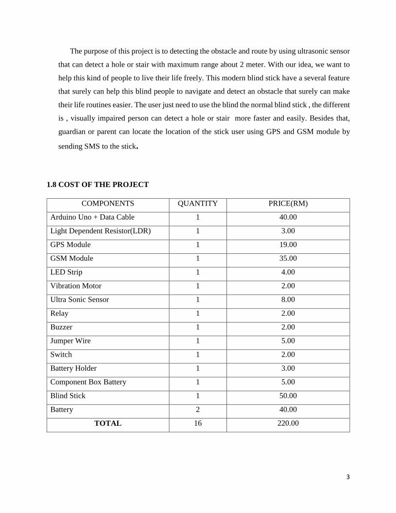
The purpose of this project is to detecting the obstacle and route by using ultrasonic sensor
that can detect a hole or stair with maximum range about 2 meter. With our idea, we want to
help this kind of people to live their life freely. This modern blind stick have a several feature
that surely can help this blind people to navigate and detect an obstacle that surely can make
their life routines easier. The user just need to use the blind the normal blind stick , the different
is , visually impaired person can detect a hole or stair more faster and easily. Besides that,
guardian or parent can locate the location of the stick user using GPS and GSM module by
sending SMS to the stick.
1.8 COST OF THE PROJECT
COMPONENTS QUANTITY PRICE(RM)
Arduino Uno + Data Cable 1 40.00
Light Dependent Resistor(LDR) 1 3.00
GPS Module 1 19.00
GSM Module 1 35.00
LED Strip 1 4.00
Vibration Motor 1 2.00
Ultra Sonic Sensor 1 8.00
Relay 1 2.00
Buzzer 1 2.00
Jumper Wire 1 5.00
Switch 1 2.00
Battery Holder 1 3.00
Component Box Battery 1 5.00
Blind Stick 1 50.00
Battery 2 40.00
TOTAL 16 220.00
4
CHAPTER 2
LITERATURE REVIEW
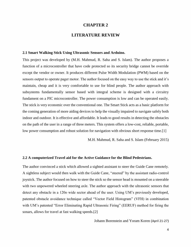
2.1 Smart Walking Stick Using Ultrasonic Sensors and Arduino.
This project was developed by (M.H. Mahmud, R. Saha and S. Islam). The author proposes a
function of a microcontroller that have code protected so its security bridge cannot be override
except the vendor or owner. It produces different Pulse Width Modulation (PWM) based on the
sensors output to operate pager motor. The author focused on the easy way to use the stick and it’s
maintain, cheap and it is very comfortable to use for blind people. The author approach with
subsystems fundamentally sensor based with integral scheme is designed with a circuitry
fundament on a PIC microcontroller. The power consumption is low and can be operated easily.
The stick is very economic over the conventional one. The Smart Stick acts as a basic platform for
the coming generation of more aiding devices to help the visually impaired to navigate safely both
indoor and outdoor. It is effective and affordable. It leads to good results in detecting the obstacles
on the path of the user in a range of three meters. This system offers a low-cost, reliable, portable,
low power consumption and robust solution for navigation with obvious short response time.[1]
M.H. Mahmud, R. Saha and S. Islam (February 2015)
2.2 A computerized Travel aid for the Active Guidance for the Blind Pedestrians.
The author convinced a stick which allowed a sighted assistant to steer the Guide Cane remotely.
A sightless subject would then walk with the Guide Cane, “steered” by the assistant radio-control
joystick. The author focused on how to steer the stick so the sensor head is mounted on a steerable
with two unpowered wheeled steering axle. The author approach with the ultrasonic sensors that
detect any obstacle in a 120o wide sector ahead of the user. Using UM’s previously developed,
patented obstacle avoidance technique called “Vector Field Histogram” (VFH) in combination
with UM’s patented “Error Eliminating Rapid Ultrasonic Firing” (EERUF) method for firing the
sonars, allows for travel at fast walking speeds.[2]
Johann Borenstein and Yoram Koren (April 21-27)
5
2.3 A Multidimensional Walking Aid for Visually Impaired Using Ultrasonic Sensors with
Voice Guidance.
The author propose that voice can being consequently activate by microcontroller when detect any
obstacle to warn the sightless subject. The author approach using with a 40 KHz signal sent out by
the ultrasonic transmitter. This will be reflected back to the ultrasonic receiver in case there is an
obstacle along the pathway of the stick, and this activates one of the input pin of the
microcontroller. Once this happened, the microcontroller will consequently activate the voice
recording microchip which then gives the relevant output via the speaker. The author focused on
how to make the voice guidance as a platform to ease and help the sightless subject.[3]
Olakanmi (August 2014)
2.4 Obstacle Detection, Artificial vision and Real-time assistance via GPS
The author convinced the Global Positioning System (GPS) is to identify the position and
orientation and location of the blind person any of those solutions rely on GPS technology. The
author focused on the GPS to make use of the data stored to compare with the destination location
of the user. By this it can trace out the distance from the destination and produce an alarm to alert
the user in advance. The author conclude The proposed combination of various working units
makes a real-time system that monitors position of the user and provides dual feedback making
navigation more safe and secure. The author approach with Microcontroller that intergrated using
Global Positioning System(GPS).[4]
Dambhare, Shruti and A.Sakhare (2011)
6
2.5 Implementation of Microcontroller Based Mobility Aid for Visually Impaired People
The author conviced the proposed that LDR gives a very high resistance value ranging up to 2MΩ
and in the day time or when there is sun light it give a low resistance ranging to 100Ω and
sometimes below. From the voltage divider network at day time the voltage from the LDR is lower
there by making pin 2 lower than pin 3 of the comparator giving an output voltage of 0V and at
night the VLDR is high making pin 2 greater and the comparator output 5V. The author focused
on how LDR can function on white cane with the proper circuit. The system consists of an
ultrasonic sensor for obstacle detection, a and a light dependent resistor for dark detection. Each
sensor is differentiated from one another through pattern of sounds.[5]
E. J. Chukwunazo and G. M. Onengiye (2015)
7
CHAPTER 3
METHODOLOGY
3.1 BACKGROUND
The methodology is the general research strategy that outlines the way in which research
is to be undertaken and among other things, identifies the methods to be used in it. These methods,
described in the methodology, define the means or modes of data collection or, sometimes how a
specific result is to be calculated.
For our project the information about the visually impaired people has been collected
throughout every source that leads to our project. All of this information has been used to do our
project which is Modern Blind Stick.
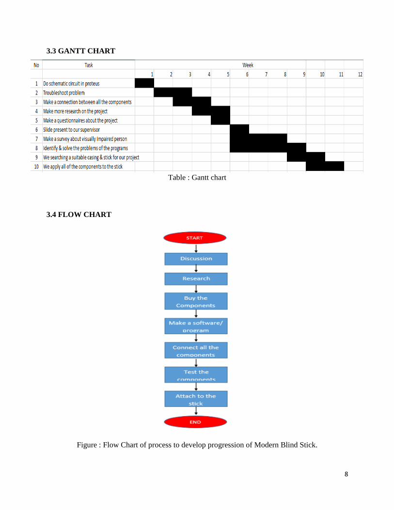
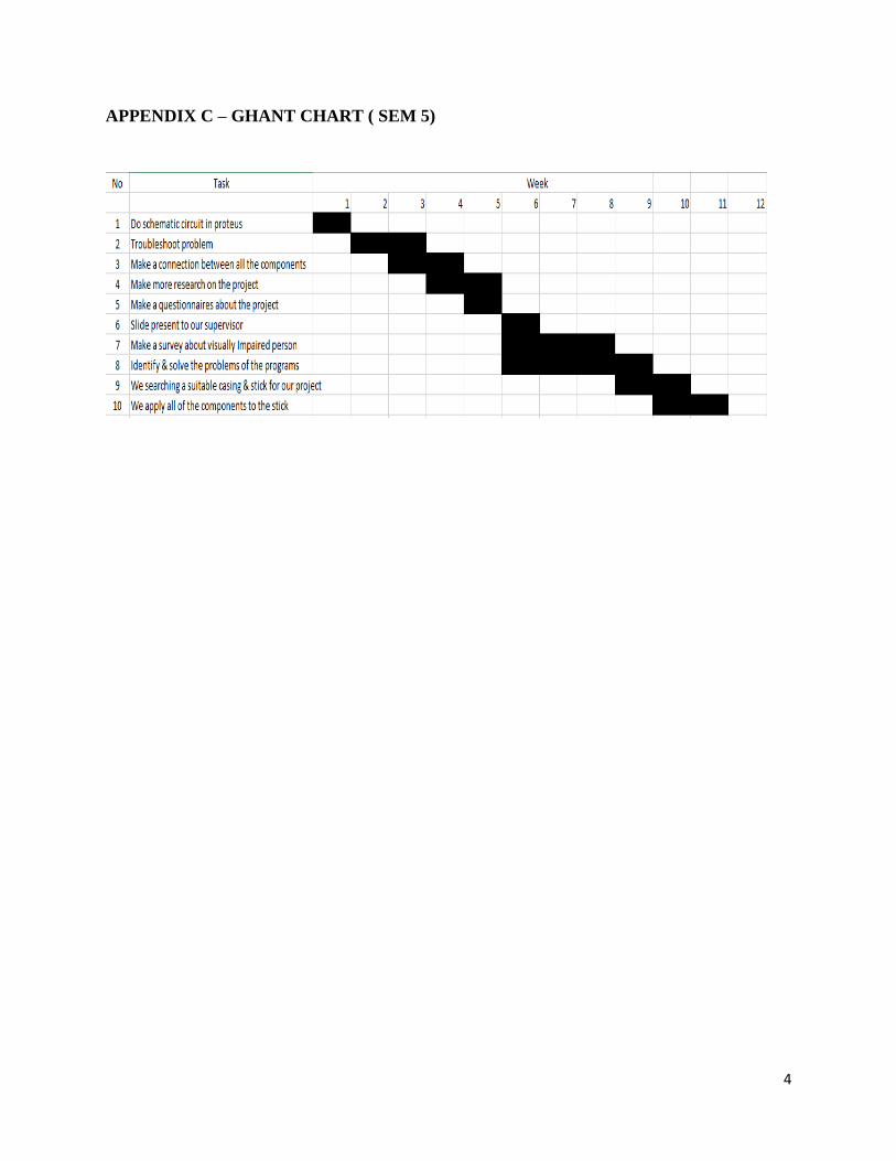
3.2 PLANNING OF PROJECT FOR MODERN BLIND STICK
In ensuring the Modern Blind Stick can be done appropriately, a project planning by using
Gantt charts has been prepared. In this Gantt chart, schedule of plan and subsequently report
progress within the project environment has been stated clearly. Initially, in this project, the scope
is defined with the appropriate methods for completing the project are determined.
8
3.3 GANTT CHART
Table : Gantt chart
3.4 FLOW CHART
Figure : Flow Chart of process to develop progression of Modern Blind Stick.
9
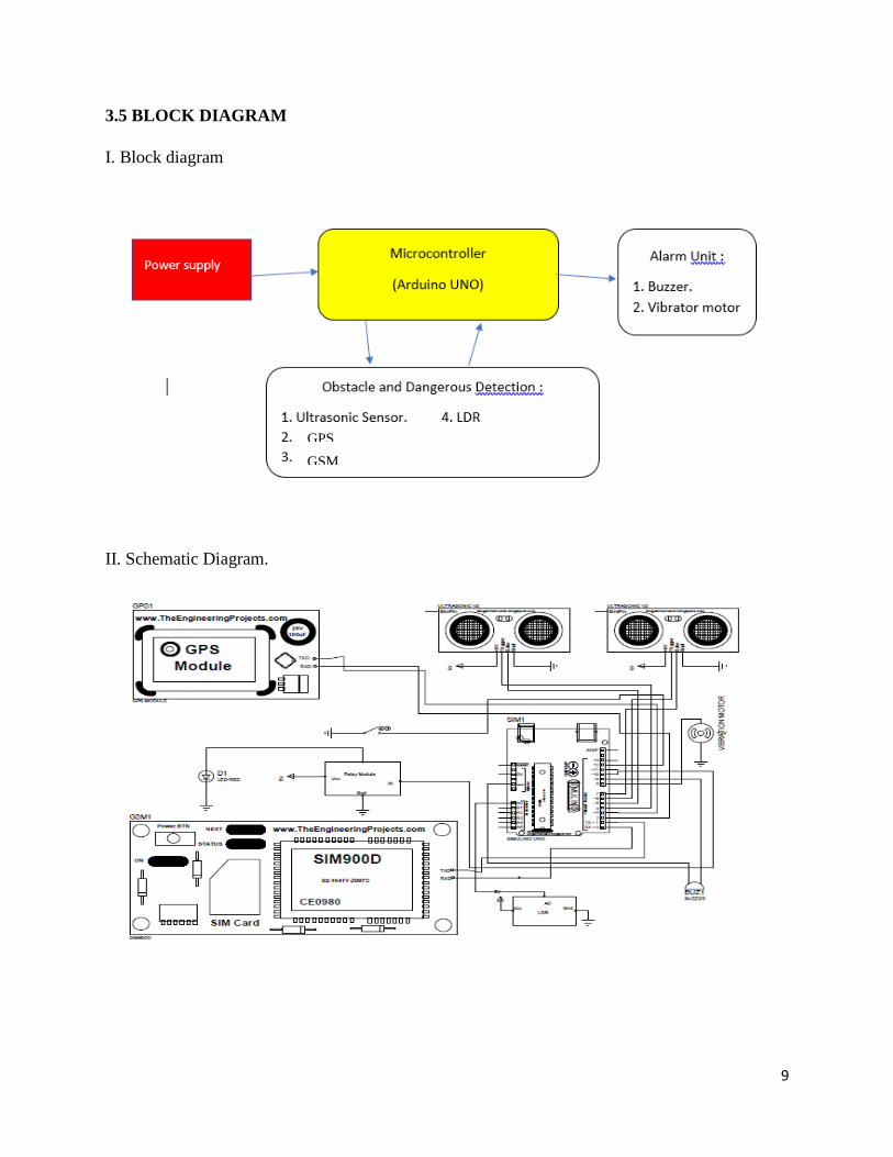
3.5 BLOCK DIAGRAM
I. Block diagram
II. Schematic Diagram.
GPS
GSM

10
HALFWAY PROJECT DESIGN - SEMESTER 4
1. Arduino UNO R3 4. LED
2. Protoboard 5. Buzzer
3. Jumper Wires 6. Ultrasonic Sensor
HALFWAY PROJECT DESIGN - SEMESTER 5
1. Arduino UNO R3 4. LED 7. GSM Module
2. Relay Module 5. Buzzer 8. GPS Module
3. Jumper Wires 6. Ultrasonic Sensor 9. LDR Module
11
3.6 LIST OF COMPONENTS
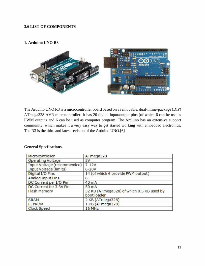
1. Arduino UNO R3
The Arduino UNO R3 is a microcontroller board based on a removable, dual-inline-package (DIP)
ATmega328 AVR microcontroller. It has 20 digital input/output pins (of which 6 can be use as
PWM outputs and 6 can be used as computer program. The Arduino has an extensive support
community, which makes it a very easy way to get started working with embedded electronics.
The R3 is the third and latest revision of the Arduino UNO.[6]
General Specfications.
12
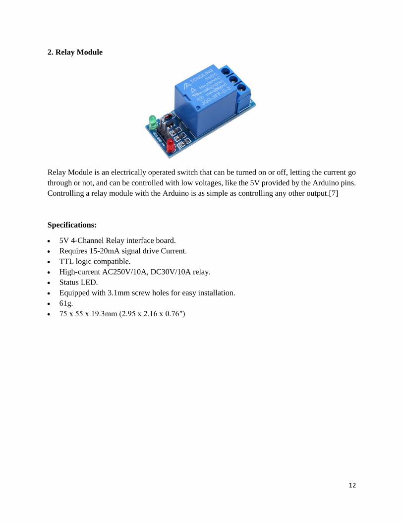
2. Relay Module
Relay Module is an electrically operated switch that can be turned on or off, letting the current go
through or not, and can be controlled with low voltages, like the 5V provided by the Arduino pins.
Controlling a relay module with the Arduino is as simple as controlling any other output.[7]
Specifications:
5V 4-Channel Relay interface board.
Requires 15-20mA signal drive Current.
TTL logic compatible.
High-current AC250V/10A, DC30V/10A relay.
Status LED.
Equipped with 3.1mm screw holes for easy installation.
61g.
75 x 55 x 19.3mm (2.95 x 2.16 x 0.76″)

13
3. Light Emitting Diode(LED)
A light-emitting diode (LED) is a semiconductor light source that emits light when current flows
through it. Electrons in the semiconductor recombine with electron holes, releasing energy in the
form of photons. The color of the light (corresponding to the energy of the photons) is determined
by the energy required for electrons to cross the band gap of the semiconductor.[5] White light is
obtained by using multiple semiconductors or a layer of light-emitting phosphor on the
semiconductor device.[8]
Specification of LED.
WAVELENGTH RANGE (NM)
COLOUR VF @ 20MA MATERIAL
< 400 Ultraviolet 3.1 - 4.4 Aluminium nitride (AlN) Aluminium gallium nitride (AlGaN) Aluminium gallium indium nitride (AlGaInN)
400 - 450 Violet 2.8 - 4.0 Indium gallium nitride (InGaN)
450 - 500 Blue 2.5 - 3.7 Indium gallium nitride (InGaN) Silicon carbide (SiC)
500 - 570 Green 1.9 - 4.0 Gallium phosphide (GaP) Aluminium gallium indium phosphide (AlGaInP) Aluminium gallium phosphide (AlGaP)
570 - 590 Yellow 2.1 - 2.2 Gallium arsenide phosphide (GaAsP) Aluminium gallium indium phosphide (AlGaInP) Gallium phosphide (GaP)
590 - 610 Orange / amber 2.0 - 2.1 Gallium arsenide phosphide (GaAsP) Aluminium gallium indium phosphide (AlGaUInP) Gallium phosphide (GaP)
610 - 760 Red 1.6 - 2.0 Aluminium gallium arsenide (AlGaAs) Gallium arsenide phosphide (GaAsP) Aluminium gallium indium phosphide (AlGaInP) Gallium phosphide (GaP)
> 760 Infrared < 1.9 Gallium arsenide (GaAs) Aluminium gallium arsenide (AlGaAs)
14
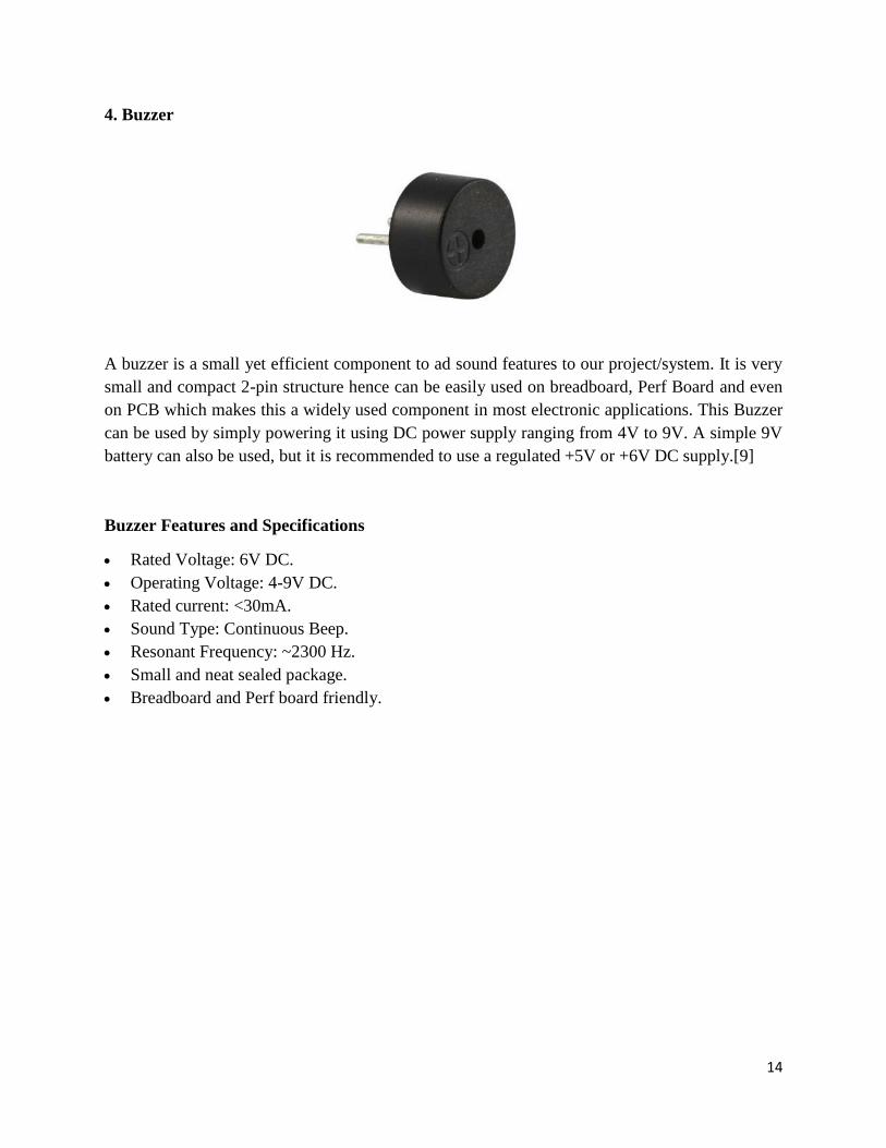
4. Buzzer
A buzzer is a small yet efficient component to ad sound features to our project/system. It is very
small and compact 2-pin structure hence can be easily used on breadboard, Perf Board and even
on PCB which makes this a widely used component in most electronic applications. This Buzzer
can be used by simply powering it using DC power supply ranging from 4V to 9V. A simple 9V
battery can also be used, but it is recommended to use a regulated +5V or +6V DC supply.[9]
Buzzer Features and Specifications
Rated Voltage: 6V DC.
Operating Voltage: 4-9V DC.
Rated current: <30mA.
Sound Type: Continuous Beep.
Resonant Frequency: ~2300 Hz.
Small and neat sealed package.
Breadboard and Perf board friendly.
15
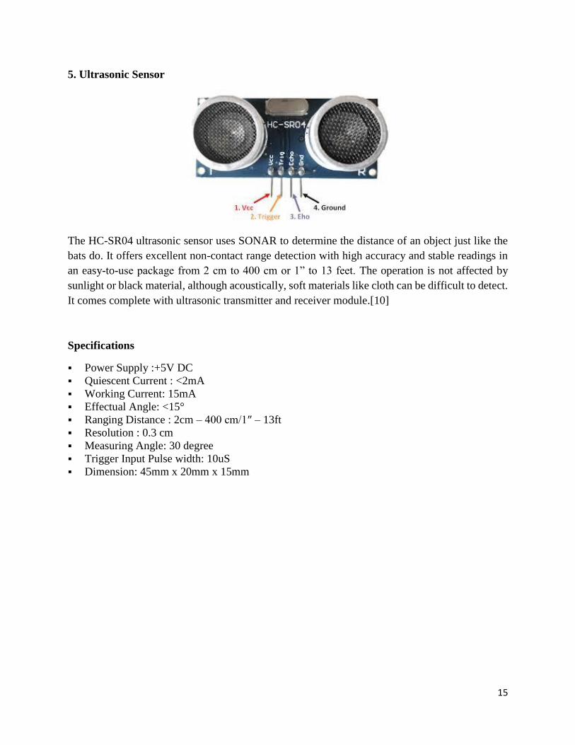
5. Ultrasonic Sensor
The HC-SR04 ultrasonic sensor uses SONAR to determine the distance of an object just like the
bats do. It offers excellent non-contact range detection with high accuracy and stable readings in
an easy-to-use package from 2 cm to 400 cm or 1” to 13 feet. The operation is not affected by
sunlight or black material, although acoustically, soft materials like cloth can be difficult to detect.
It comes complete with ultrasonic transmitter and receiver module.[10]
Specifications
Power Supply :+5V DC
Quiescent Current : <2mA
Working Current: 15mA
Effectual Angle: <15°
Ranging Distance : 2cm – 400 cm/1″ – 13ft
Resolution : 0.3 cm
Measuring Angle: 30 degree
Trigger Input Pulse width: 10uS
Dimension: 45mm x 20mm x 15mm
16
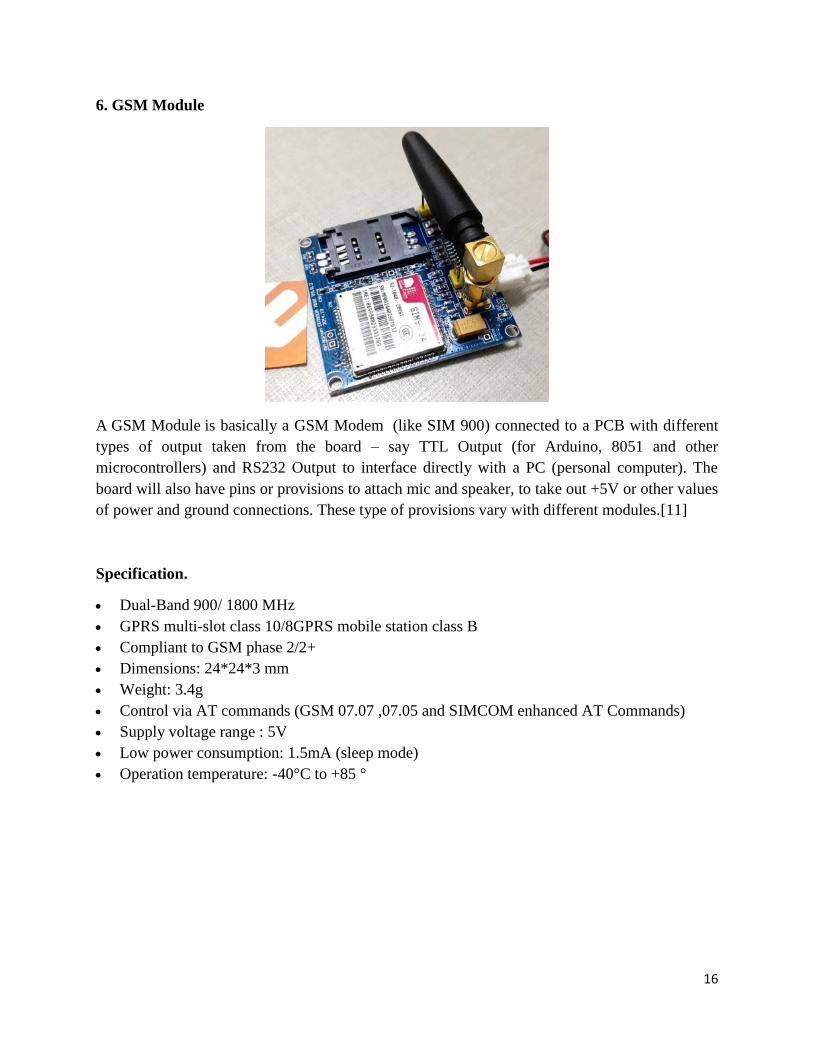
6. GSM Module
A GSM Module is basically a GSM Modem (like SIM 900) connected to a PCB with different
types of output taken from the board – say TTL Output (for Arduino, 8051 and other
microcontrollers) and RS232 Output to interface directly with a PC (personal computer). The
board will also have pins or provisions to attach mic and speaker, to take out +5V or other values
of power and ground connections. These type of provisions vary with different modules.[11]
Specification.
Dual-Band 900/ 1800 MHz
GPRS multi-slot class 10/8GPRS mobile station class B
Compliant to GSM phase 2/2+
Dimensions: 24*24*3 mm
Weight: 3.4g
Control via AT commands (GSM 07.07 ,07.05 and SIMCOM enhanced AT Commands)
Supply voltage range : 5V
Low power consumption: 1.5mA (sleep mode)
Operation temperature: -40°C to +85 °
17
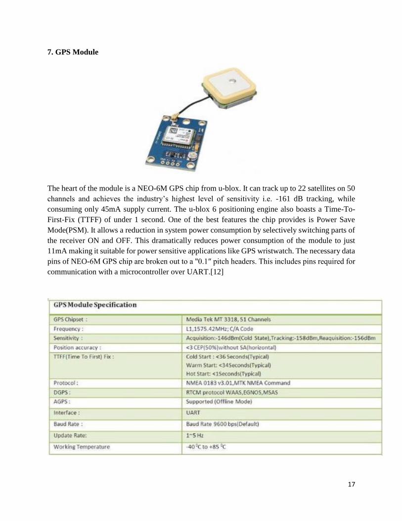
7. GPS Module
The heart of the module is a NEO-6M GPS chip from u-blox. It can track up to 22 satellites on 50
channels and achieves the industry’s highest level of sensitivity i.e. -161 dB tracking, while
consuming only 45mA supply current. The u-blox 6 positioning engine also boasts a Time-To-
First-Fix (TTFF) of under 1 second. One of the best features the chip provides is Power Save
Mode(PSM). It allows a reduction in system power consumption by selectively switching parts of
the receiver ON and OFF. This dramatically reduces power consumption of the module to just
11mA making it suitable for power sensitive applications like GPS wristwatch. The necessary data
pins of NEO-6M GPS chip are broken out to a "0.1″ pitch headers. This includes pins required for
communication with a microcontroller over UART.[12]

18
8. Light Dependent Resistor(LDR) Module
The LDR Sensor Module is used to detect the presence of light / measuring the intensity of light.
The output of the module goes high in the presence of light and it becomes low in the absence of
light. The sensitivity of the signal detection can be adjusted using potentiometer.[13]
Specification:
Input Voltage: DC 3.3V to 5V
Output: Analog and Digital
Sensitivity adjustable

19
CHAPTER 4
RESULT AND DISCUSSION
4.1 ANALYSIS PROJECT
After we designed and programmed the Modern Blind Stick to the needed standard, this innovation
product has been functioning well. We tested the Modern Blind Stick with certain obstacles, hazard
, range and distance and it work successfully as we programed the Modern Blind Stick.
Analysis about the point of view about the visually impaired person walk at the public. First
analysis is the visually impaired person to walk at the public independently. Second, the real time
location of the visually impaired person at the public. Third, the safety of the visually impaired
person at the public. The analysis shows the problems as the visually impaired person the risk
when walking at the public .
20
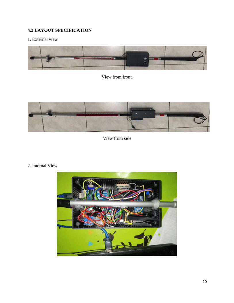
4.2 LAYOUT SPECIFICATION
1. External view
View from front.
View from side
2. Internal View
21
4.3 DISCUSSION
Based on the theory, Visual impaired person or also known as vision impairment or vision
loss, is a decreased ability to see to a degree that causes problems not fixable by usual means, such
as glasses Some also include those who have a decreased ability to see because they do not have
access to glasses or contact lenses. Visual impairment is often defined as a best corrected visual
acuity of worse than either 20/40 or 20/60. The term blindness is used for complete or nearly
complete vision loss.[6] Visual impairment may cause people difficulties with normal daily
activities such as driving, reading, socializing, and walking.
The most common causes of visual impairment globally are uncorrected refractive
errors (43%), cataracts (33%), and glaucoma (2%). Refractive errors include near-
sightedness, far-sightedness, presbyopia, and astigmatism. Cataracts are the most common cause
of blindness. Other disorders that may cause visual problems include age-related macular
degeneration, diabetic retinopathy, corneal clouding, childhood blindness, and a number
of infections. Visual impairment can also be caused by problems in the brain due
to stroke, premature birth, or trauma among others. These cases are known as cortical visual
impairment. Screening for vision problems in children may improve future vision and educational
achievement. Screening adults without symptoms is of uncertain benefit. Diagnosis is by an eye
exam.
The World Health Organization (WHO) estimates that 80% of visual impairment is either
preventable or curable with treatment. This includes cataracts, the infections river
blindness and trachoma, glaucoma, diabetic retinopathy, uncorrected refractive errors, and some
cases of childhood blindness. Many people with significant visual impairment benefit from vision
rehabilitation, changes in their environment, and assistive devices.
As of 2015 there were 940 million people with some degree of vision loss. 246 million had low
vision and 39 million were blind. The majority of people with poor vision are in the developing
world and are over the age of 50 years. Rates of visual impairment have decreased since the
1990s. Visual impairments have considerable economic costs both directly due to the cost of
treatment and indirectly due to decreased ability to work.
The solution for visually impaired person to walking is by using ‘White Cane’. A white cane is a
device used by many people who are blind or visually impaired. A white cane primarily allows its
user to scan their surroundings for obstacles or orientation marks, but is also helpful for onlookers
in identifying the user as blind or visually impaired and taking appropriate care. The latter is the
reason for the cane's white color, which in many jurisdictions is mandatory.
While the white cane is commonly accepted as a "symbol of blindness", different countries still
have different rules concerning what constitutes a "cane for the blind". In the United Kingdom and
also in Malaysia, the white cane indicates that the individual has a visual impairment but normal
hearing; with red bands added, it indicates that the user is deafblind.

22
Based on our research, many visually impaired person suffer from serious visual impairments
preventing them from travelling independently. They need to use a wide range of tools and
techniques to help them in their mobility. One of these techniques is orientation and mobility
specialist who helps the visually impaired and blind people and trains them to move on their own
independently and safely depending on their other remaining senses.
Nowadays, as a parent or guardian, we don’t want our children or our care’s get into trouble when
walking at public or somewhere else. Vision loss has a significant impact on their lives for those
who experience it as well as on their families, their friends, and society. The complete loss or the
deterioration of existing eyesight can feel frightening and overwhelming, leaving those affected to
wonder about their ability to maintain their independence, pay for needed medical care, retain
employment, and provide for themselves and their families. It’s a high risk to live in a lifetime.
So we create a product that can help the visually impaired person to walk at the public
independently. The Modern Blind Stick function is to help the visually impaired person walk more
easier and more independent. Modern Blind Stick also can help this blind people to navigate routes
and detect an obstacle that surely can make their life routines easier. The user just need to use the
blind the normal blind stick , the different is , blind people can detect a hole or stair more faster
and easily . Besides that , guardian or parent also can locate the location of the stick user using
Global Positioning System(GPS) and Global System for Mobile Communication (GSM) module.
To assist in tracking the location, this Modern Blind Stick utilizes GPS to determine the location
and send it via SMS to locate the location of the user Modern Blind Stick.
23
CHAPTER 5
CONCLUSION AND RECOMMENDATION
5.1 CONCLUSION
In the end of our project, we can conclude that our project can reduce the number of risk
and injuries for the visually impaired person when walking at public. Nowadays, even at young
age experience the visually impairment. This thing cannot be taken so lightly as they know how
much risk could it be. If the number of risk and injuries increasing rapidly, the kid or the person
will loss their spirit to walk independently.
The Modern Blind Stick acts as a basic platform for the coming generation of more aiding devices
to help the visually impaired to navigate safely both indoor and outdoor. It is effective and
affordable. It leads to good results in detecting the obstacles on the path of the user in a range of
two meters. Though the system is hard-wired with sensors and other components, it's light in
weight. Further aspects of this system can be improved via wireless connectivity between the
system components, thus, increasing the range of the ultrasonic sensor and implementing a
technology for determining the speed of approaching obstacles.
5.2 RECOMMENDATION
In the future, we hope that our project can be commercialize as there are many benefit such as to
reduce the number of risk and injuries for the visually impaired people. Our life are very priceless
and cannot be replace. Because we all just live only once, so seize our life with positive vibes. We
hope we can improvise our project if there is a thing that can make our product more quality than
before.
24
5.3 REFERENCE
1. https://www.researchgate.net/publication/272080365_The_Prevalence_and_Causes_of_Visual
Impairment_and_Blindness_Among_Older_Adults_in_the_City_of_Lodz_Poland
2. https://pdfs.semanticscholar.org/8919/29ae290dcacc84f0b0002ea101eac63c11e2.pdf
3. http://www.mecs-press.net/ijisa/ijisa-v6-n8/v6n8-6.html
4. https://www.semanticscholar.org/paper/Smart-stick-for-Blind%3A-Obstacle-Detection%2C-
vision-Dambhare
5. https://pdfs.semanticscholar.org/35a4/74e95b193963f2bb4dbca220a76af40a13ee.pdf
6. https://store.arduino.cc/usa/arduino-uno-rev3
7. https://randomnerdtutorials.com/guide-for-relay-module-with-arduino/
8. https://en.wikipedia.org/wiki/Light-emitting_diode
9. https://components101.com/buzzer-pinout-working-datasheet
10. https://www.tutorialspoint.com/arduino/arduino_ultrasonic_sensor.htm
11. https://www.mybotic.com.my/products/SIM900A-GSM-GPRS-Module/1783
12. https://create.arduino.cc/projecthub/ruchir1674/how-to-interface-gps-module-neo-6m-with-
arduino-8f90ad
13. https://wiki.eprolabs.com/index.php?title=LDR_module
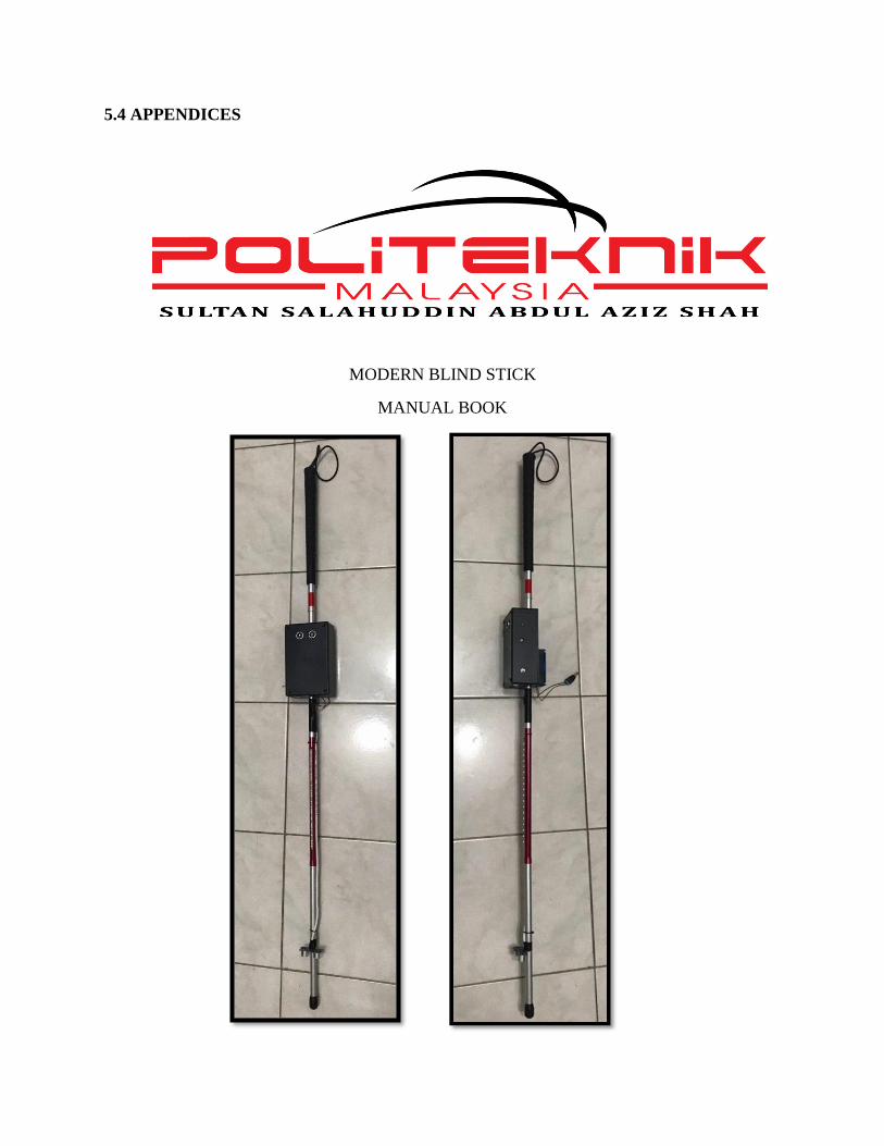
5.4 APPENDICES
MODERN BLIND STICK
MANUAL BOOK
1
TEAM MEMBERS :
1. SYED HAZIQ AFIF BIN SYED MOHD FAZLI (08DEP17F2017)
2. MUHAMMAD HAIKAL IQMAL BIN JAMALUDDIN (08DEP17F2018)
SUPERVISOR NAME :
1. PN AKMARYA SYUKHAIRILNISAH BT MOHD AKHIR
2. PN ZAITUN BINTI TAAT
3. PN ASTRAHUDA KAMARULAINI BT MOHF FAHMI
4. EN KHAIROL NAPISHAM BI ABD RAZAK
2
SOP OF OPERATION TO USE THE MODERN BLIND STICK
1.0 OBJECTIVE : -Develop a hardware prototype for modern blind stick
-To help the blind people navigate the route at their best
-Design and construct the stick to build a “modern blind stck”
- Build software that suitable with the blind people
2.0 SCOPE : -Visual impaired person that having trouble to navigate.
3.0 CAUTION : -BEFORE READING THE PROCEDURE, MAKE SURE
READ EVERY LINE FOR THE MODERN BLIND STICK
TO WORK PROPERLY
4.0 PROCEDURE :
OPERATIONAL PROCEDURE
1. Make sure the stick have been put the enough power supply
2. Is easier to use the stick at the crowd place
3. Make sure the led turn red to make sure the system is ready
4. Make sure the GSM and GPS is activate to locate the location
5. To change the “MODE” pull the switch button
6. Modern Blind Stick buzzer will sound when the system is started
7. Modern blind stick will sound when its detect a hole
8. The LED will be on when at the dark place
9. To locate the location , send sms to the modern blind stick
10. Make sure the both sim have enough credit to get the feedback
TURNING OFF THE MODERN BLIND STICK
11. To turn off the modern blind stick , just pull of the power supply.
12. Put it at the safe place to avoid any excident.
3
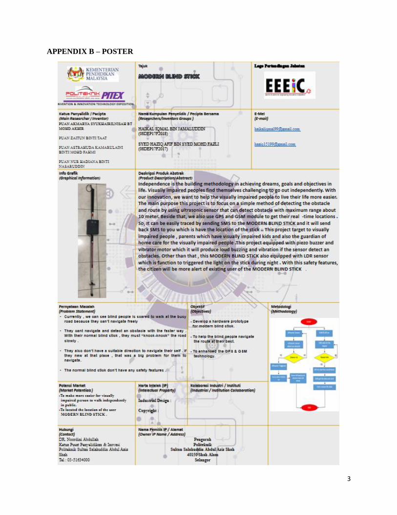
APPENDIX B – POSTER
4
APPENDIX C – GHANT CHART ( SEM 5)
5
APPENDIX D – AKUAN SUMPAH
COPYRIGHT ACT 1987
IN THE MATTER OF Section 26A (3) (b), Copyright Act
1987 (Act 332)
and
IN THE MATTER of the Copyright
(Voluntary Notification) Regulations 2012 [P.U.(A)
160]
STATUTORY DECLARATION I, WAN ROSEMEHAH BINTI WAN OMAR (NRIC No.:740506-03-6080)of full age and care of Politeknik
Sultan Salahuddin Abdul Aziz Shah, Persiaran Usahawan, Seksyen U1, 40150 Shah Alam,
Selangor, Malaysia sincerely and solemnly declare as follows:
1. I am the Head of Research and Innovation Unit, Politeknik Sultan Salahuddin Abdul
Aziz Shah, a higher learning institution incorporated under the laws of Malaysia with an
address at Persiaran Usahawan, Seksyen U1, 40150 Shah Alam, Selangor, Malaysia
(hereinafter referred as “PSA”).
2. I am duly authorized to make this Statutory Declaration on behalf of PSA. Unless otherwise
stated, the fact herein are within my knowledge or derived from the records of PSA to which
I have access.
3. I am advised and verily believe that copyright subsists in the following works title “MODERN
BLIND STICK” (hereinafter referred as “the Works”) identified accordingly below:
Exhibit No. Author and IC No. Date Completed
PSA- MODERN BLIND
STICK -JKE
1) SYED HAZIQ AFIF BIN SYED MOHD FAZLI (990115086445)
2) MUHAMMAD HAIKAL IQMAL BIN JAMALUDDIN (991004045581)
01/03/2019
The authors listed above shall collectively be referred to as the “Authors”.
4. I am advised and verily believe that copyright subsist in the Works by virtue of the following
facts:
i. The authors, were and are at all material times citizens of Malaysia, and the Works were
created and completed in Malaysia on the date set out in paragraph 3 above. The Works

6
qualify for copyright protection under the Copyright Act 1987 by virtue of Section 3 and 10
of the copyright Act, 1987.
ii. That sufficient and substantial skill, effort and time has been expanded on the Works by
the Authors to render them original in character under Section 7(3)(a) of the Copyright Act
1987.
iii. That the Works have been reduced to material form as required under Section 7(3) (b) of
the Copyright Act 1987 as at the date of completion as set out in paragraph 3 above.
5. I am advised and verily believe that at all material times PSA is the owner of the copyrights
subsisting in the said Works by virtue of the following facts:
i. that at all material times, the Authors were and are employees of PSA and the Works
were created by the Authors in the course of employment with PSA,
ii. that at all material times, the Authors were and are students of PSA and the Works were
created by the Authors in the course of fulfilment the study with PSA,
iii. that at all material times, the Works were created, developed, generated using material,
funds and other resources owned by PSA.
iv. that at all material times, the Works were created with support and supervision of
employees of PSA, and
v. that at all material times, the Works were commissioned or created under direct request
of PSA.
By virtue of Section 26(2)(a) and (b) of the Copyright Act 1987, the copyright of the said Works
are deemed to be transferred to PSA.
6. PSA now asserts copyright in the Works and hereby claims ownership in the copyright
subsisting in the Works at all material times.
7. The Works is eligible for copyright protection as literary work under the Copyright Act 1987
and by the virtue of the Copyright (Application to Other Countries) Regulations 1990, the
Berne Convention for the Protection of Literary and Artistic Works 1886 extends copyright
protection for the Works to all member countries of the Berne Convention.
8. PSA not at any time authorized any third party in Malaysia or elsewhere to reproduce any
part of the Works,
7
and I make this solemn declaration conscientiously believing the same to be true and by virtue of
Section 26A(3)(b) Copyright 1987 and the Statutory Declaration 1960.
Subscribed and solemnly declared by the abovenamed)
WAN ROSEMEHAH BINTI WAN OMAR (NRIC No.: 740506-03-6080)
at Shah Alam on )
Before me,
Commissioner for Oaths
COPYRIGHT ACT 1987
IN THE MATTER OF Section 26A (3) (b), Copyright Act
1987 (Act 332)
and
IN THE MATTER of the Copyright
(Voluntary Notification) Regulations 2012 [P.U.(A)
160]

8
APPENDIX E – SURVEY QUESTION
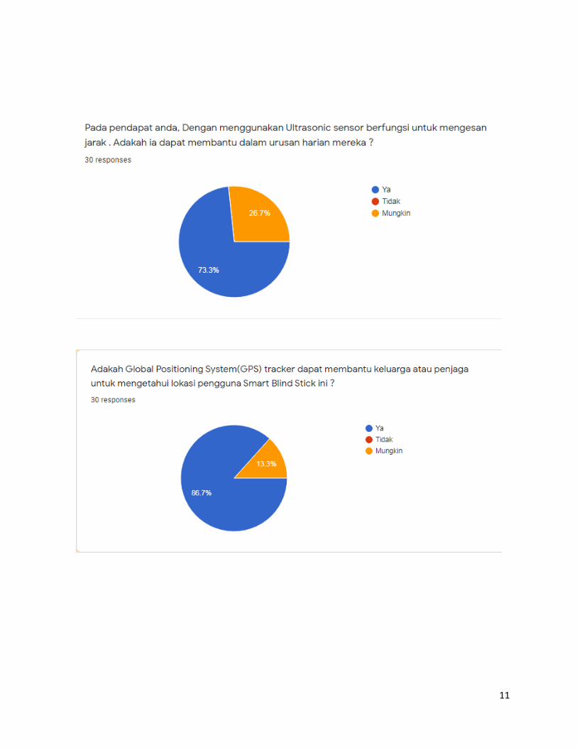
9
10
11
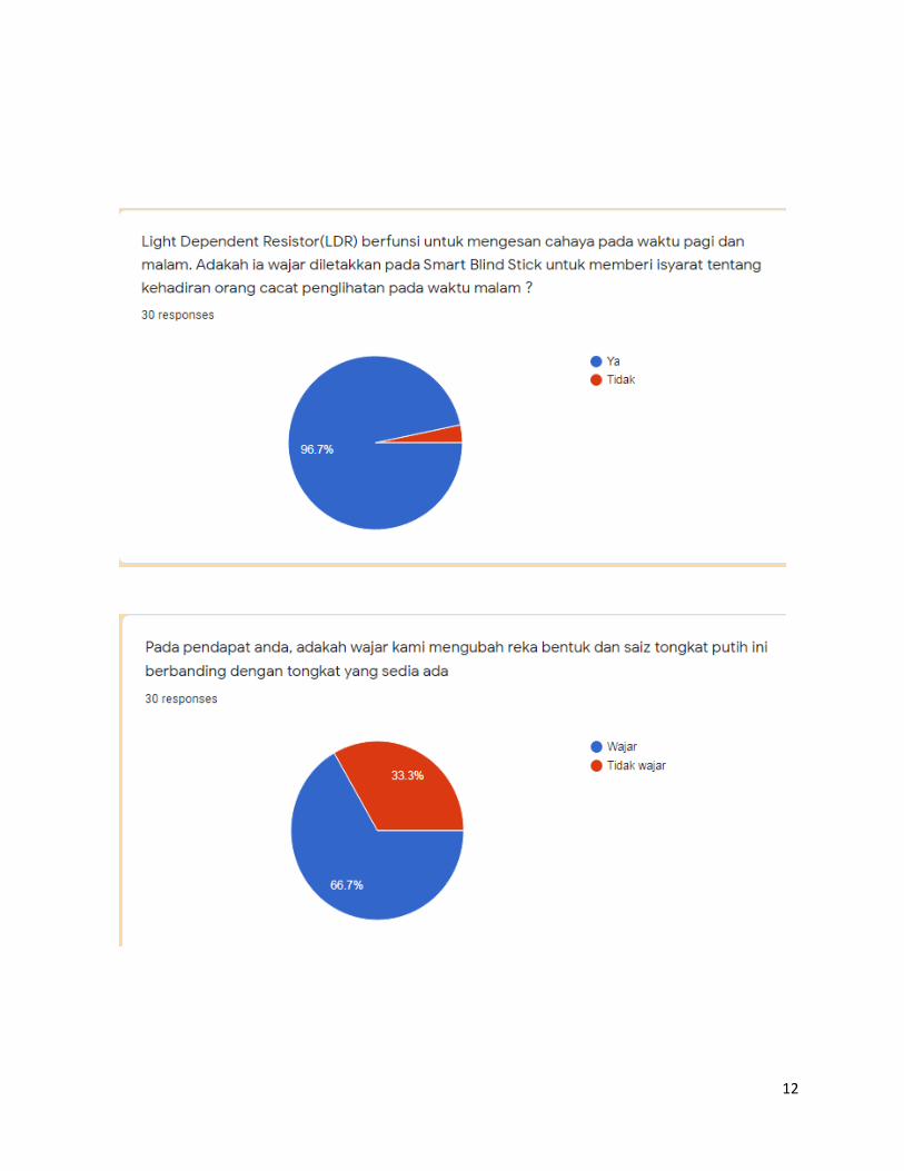
12
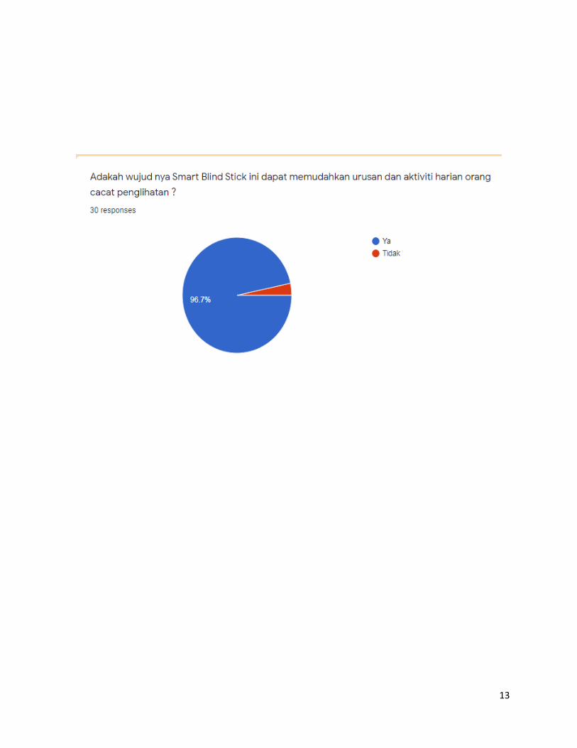
13
14
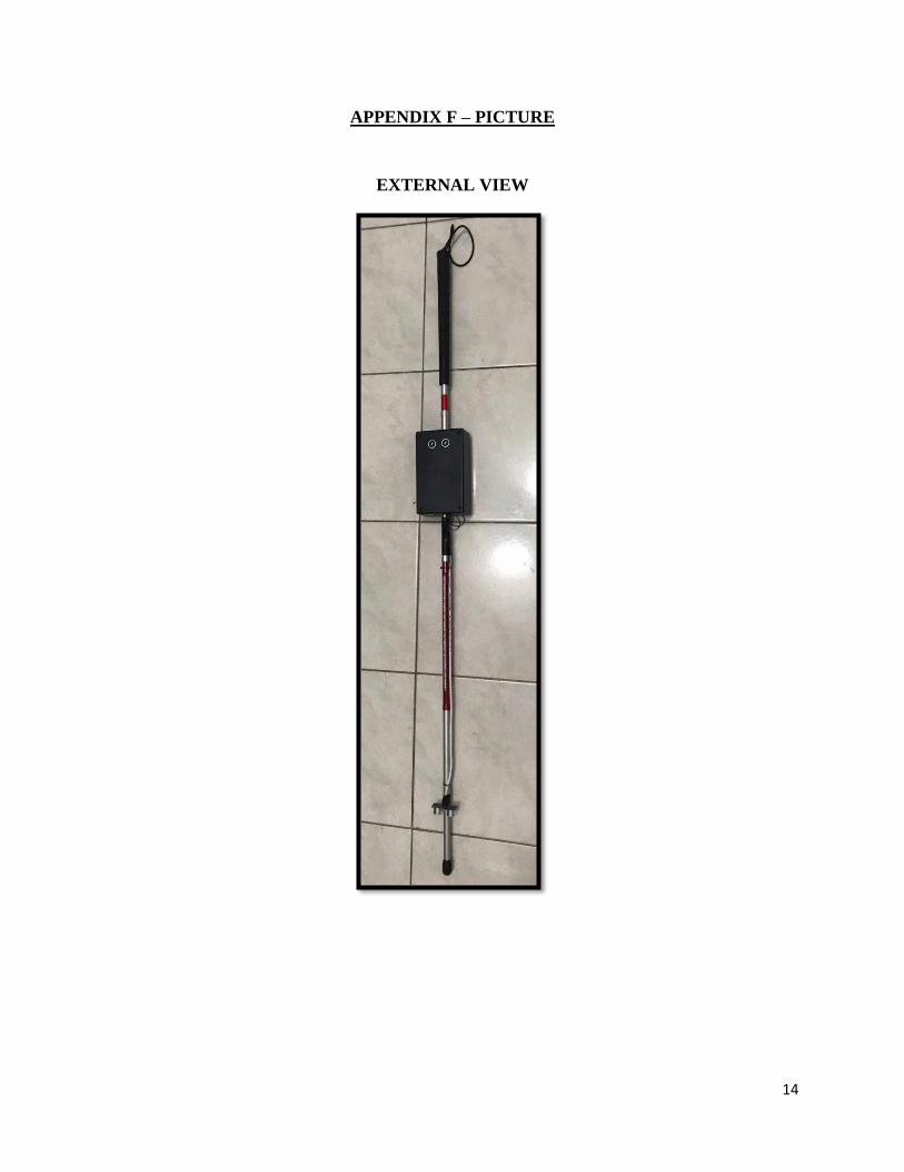
APPENDIX F – PICTURE
EXTERNAL VIEW

15
INTERNAL VIEW
16
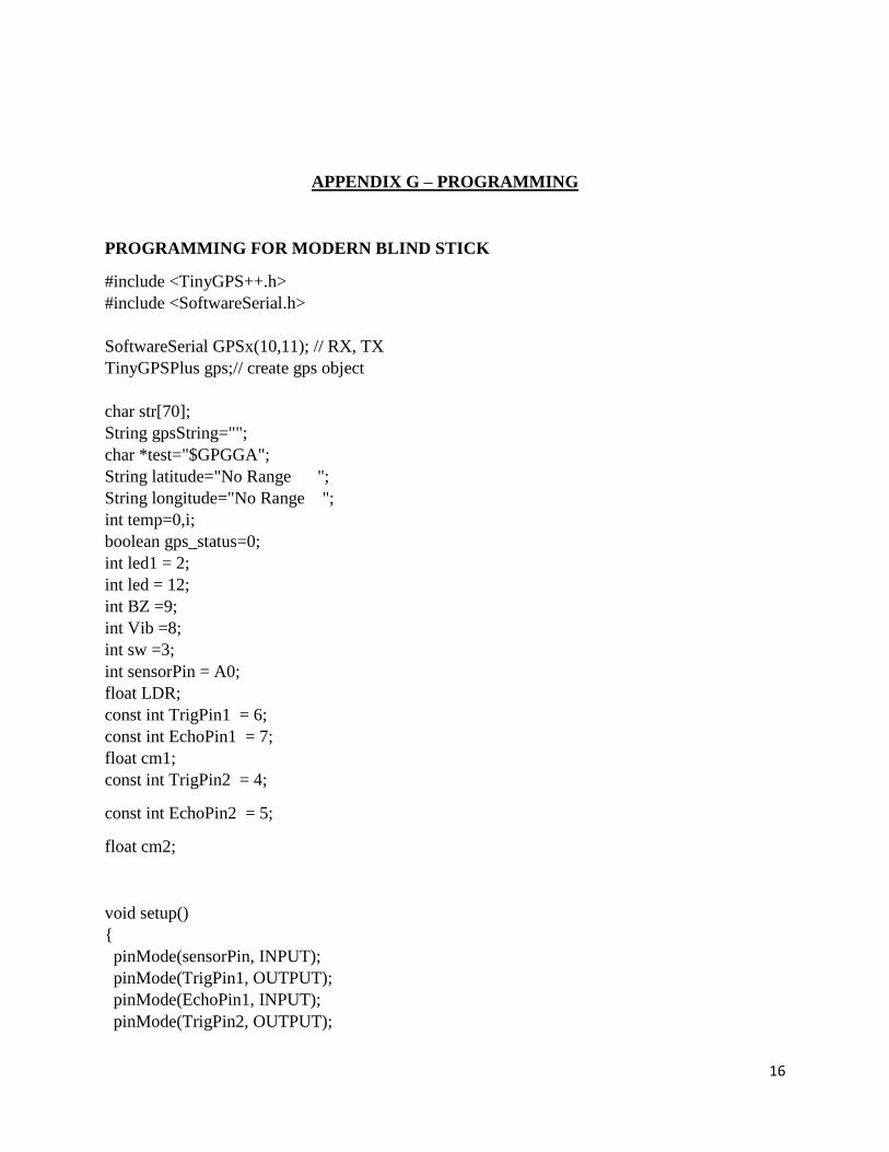
APPENDIX G – PROGRAMMING
PROGRAMMING FOR MODERN BLIND STICK
#include <TinyGPS++.h>
#include <SoftwareSerial.h>
SoftwareSerial GPSx(10,11); // RX, TX
TinyGPSPlus gps;// create gps object
char str[70];
String gpsString="";
char *test="$GPGGA";
String latitude="No Range ";
String longitude="No Range ";
int temp=0,i;
boolean gps_status=0;
int led1 = 2;
int led = 12;
int BZ =9;
int Vib =8;
int sw =3;
int sensorPin = A0;
float LDR;
const int TrigPin1 = 6;
const int EchoPin1 = 7;
float cm1;
const int TrigPin2 = 4;
const int EchoPin2 = 5;
float cm2;
void setup()
pinMode(sensorPin, INPUT);
pinMode(TrigPin1, OUTPUT);
pinMode(EchoPin1, INPUT);
pinMode(TrigPin2, OUTPUT);
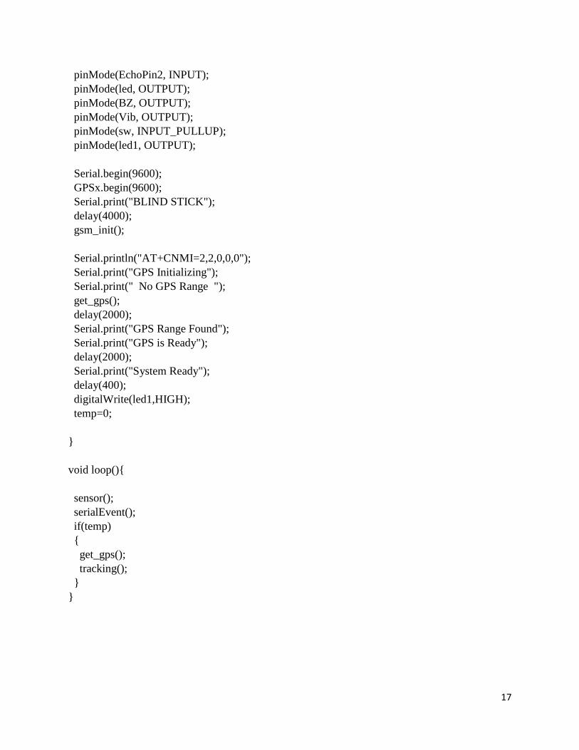
17
pinMode(EchoPin2, INPUT);
pinMode(led, OUTPUT);
pinMode(BZ, OUTPUT);
pinMode(Vib, OUTPUT);
pinMode(sw, INPUT_PULLUP);
pinMode(led1, OUTPUT);
Serial.begin(9600);
GPSx.begin(9600);
Serial.print("BLIND STICK");
delay(4000);
gsm_init();
Serial.println("AT+CNMI=2,2,0,0,0");
Serial.print("GPS Initializing");
Serial.print(" No GPS Range ");
get_gps();
delay(2000);
Serial.print("GPS Range Found");
Serial.print("GPS is Ready");
delay(2000);
Serial.print("System Ready");
delay(400);
digitalWrite(led1,HIGH);
temp=0;
void loop()
sensor();
serialEvent();
if(temp)
get_gps();
tracking();
18
void sensor()
LDR = analogRead(sensorPin);
//Serial.print("LDR=");
//Serial.print(LDR);
//Serial.println();
//delay(50);
//*********************************************************
digitalWrite(TrigPin1, LOW);
delayMicroseconds(2);
digitalWrite(TrigPin1, HIGH);
delayMicroseconds(10);
digitalWrite(TrigPin1, LOW);
cm1 = pulseIn(EchoPin1, !(LOW)) / 58.0; //map the time to centimeter//
cm1 = (int(cm1 * 100.0)) / 100.0; //keep two digits after the decimal point
//Serial.print("cm1=");
//Serial.print(cm1);
//Serial.println();
// delay(500);
//************************************************************
digitalWrite(TrigPin2, LOW);
delayMicroseconds(2);
digitalWrite(TrigPin2, HIGH);
delayMicroseconds(10);
digitalWrite(TrigPin2, LOW);
cm2 = pulseIn(EchoPin2, !(LOW)) / 58.0; //map the time to centimeter//
cm2 = (int(cm2 * 100.0)) / 100.0; //keep two digits after the decimal point
//Serial.print("cm2=");
//Serial.print(cm2);
//Serial.println();
// delay(500);
if (cm1<=50)
if (digitalRead(sw)==1)
digitalWrite(Vib,LOW);
digitalWrite(BZ,HIGH);
else
digitalWrite(Vib,HIGH);
digitalWrite(BZ,LOW);
19
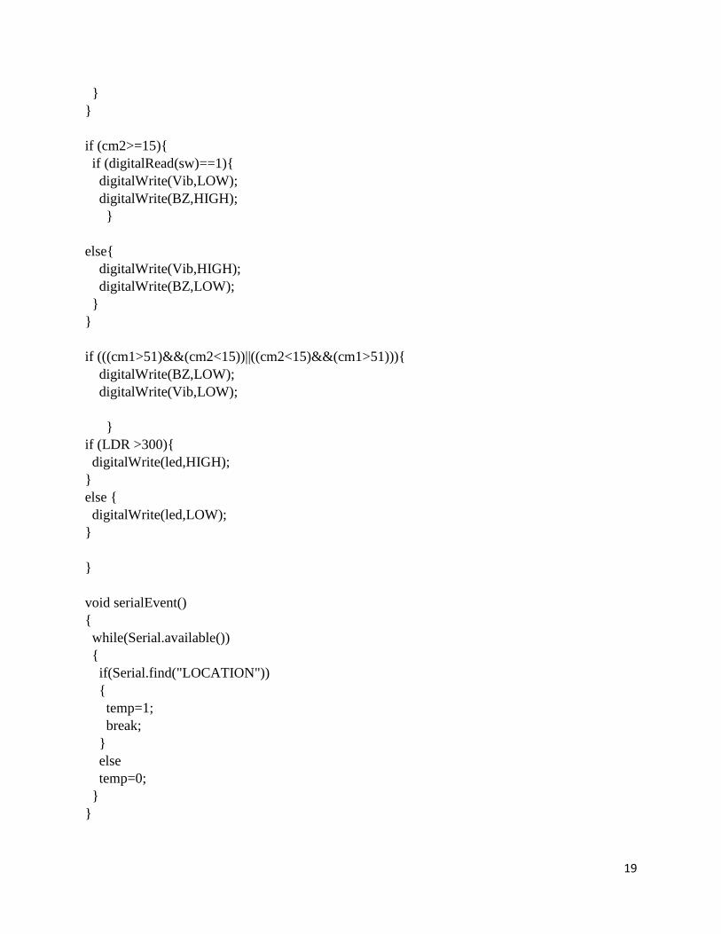
if (cm2>=15)
if (digitalRead(sw)==1)
digitalWrite(Vib,LOW);
digitalWrite(BZ,HIGH);
else
digitalWrite(Vib,HIGH);
digitalWrite(BZ,LOW);
if (((cm1>51)&&(cm2<15))||((cm2<15)&&(cm1>51)))
digitalWrite(BZ,LOW);
digitalWrite(Vib,LOW);
if (LDR >300)
digitalWrite(led,HIGH);
else
digitalWrite(led,LOW);
void serialEvent()
while(Serial.available())
if(Serial.find("LOCATION"))
temp=1;
break;
else
temp=0;
20
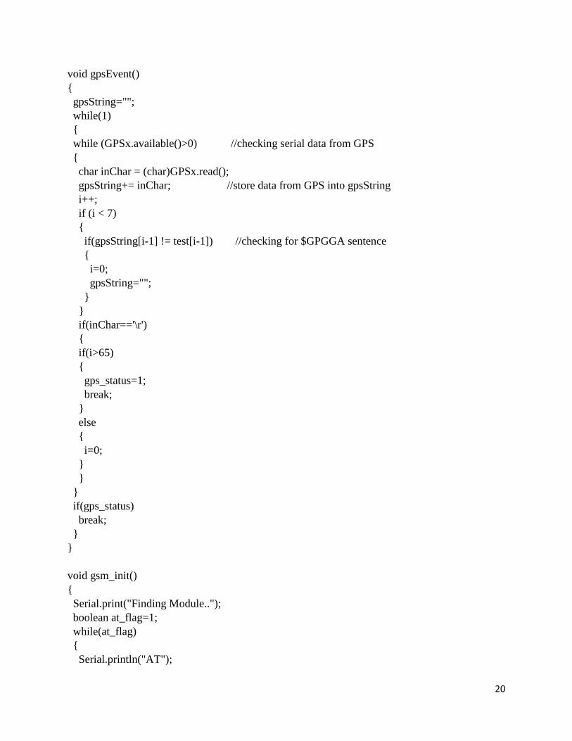
void gpsEvent()
gpsString="";
while(1)
while (GPSx.available()>0) //checking serial data from GPS
char inChar = (char)GPSx.read();
gpsString+= inChar; //store data from GPS into gpsString
i++;
if (i < 7)
if(gpsString[i-1] != test[i-1]) //checking for $GPGGA sentence
i=0;
gpsString="";
if(inChar=='\r')
if(i>65)
gps_status=1;
break;
else
i=0;
if(gps_status)
break;
void gsm_init()
Serial.print("Finding Module..");
boolean at_flag=1;
while(at_flag)
Serial.println("AT");
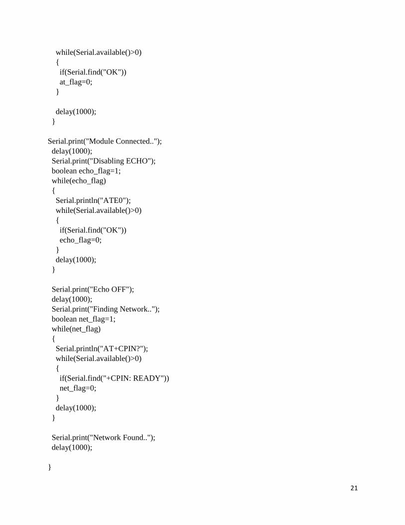
21
while(Serial.available()>0)
if(Serial.find("OK"))
at_flag=0;
delay(1000);
Serial.print("Module Connected..");
delay(1000);
Serial.print("Disabling ECHO");
boolean echo_flag=1;
while(echo_flag)
Serial.println("ATE0");
while(Serial.available()>0)
if(Serial.find("OK"))
echo_flag=0;
delay(1000);
Serial.print("Echo OFF");
delay(1000);
Serial.print("Finding Network..");
boolean net_flag=1;
while(net_flag)
Serial.println("AT+CPIN?");
while(Serial.available()>0)
if(Serial.find("+CPIN: READY"))
net_flag=0;
delay(1000);
Serial.print("Network Found..");
delay(1000);
22
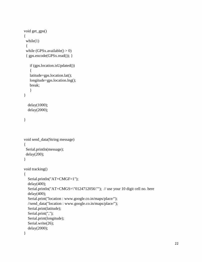
void get_gps()
while(1)
while (GPSx.available() > 0)
gps.encode(GPSx.read());
if (gps.location.isUpdated())
latitude=gps.location.lat();
longitude=gps.location.lng();
break;
delay(1000);
delay(2000);
void send_data(String message)
Serial.println(message);
delay(200);
void tracking()
Serial.println("AT+CMGF=1");
delay(400);
Serial.println("AT+CMGS=\"0124712056\""); // use your 10 digit cell no. here
delay(400);
Serial.print("location : www.google.co.in/maps/place/");
//send_data("location : www.google.co.in/maps/place/");
Serial.print(latitude);
Serial.print(",");
Serial.print(longitude);
Serial.write(26);
delay(2000);

23
APPENDIX H – DIGEST PAPER
MODERN BLIND STICK
Lecturer : i) Puan Akmarya Syukhairilnisah Bt Mohd Akhir ii) Puan Zaitun Bt Taat iii) Puan
Astrahuda Kamarulaini Bt Mohd Fahmi iv) En Khairol Napisham Bin Abd Razak
Name : i) Syed Haziq Afif Bi Syed Mohd Fazli ii)Muhammad Haikal Iqmal Bin Jamaluddin
Email : i) [email protected]
ABSTRACT :
The study focus on a simple method of detecting the obstacle and route by using a ultrasonic
sensor that can detect a hole or stair with maximum range about 15 meter. As we can see, blind
people is having their trouble to do their life routines because they can’t see even a single things .
With our idea , we want to help this kind of people to live their life freely. This modern blind stick
have a several feature that surely can help this blind people to navigate routes and detect an
obstacle that surely can make their life routines more easy. The user just need to use the blind the
normal blind stick , the different is , blind people can detect a hole or stair and more faster and
early . Beside that , guardian or parent can know the location of the stick user using GPS and GSM
module .
1.0 INTRODUCTION
Nowadays , as we can see , we can see visual impared person always use their normal blind
stick to do their activity like normal person. They use the stick to navigate their route because
they cant even see a single things . As a community , we aware and really want to help them to
make their life more easy and faster. With the normal blind stick , they will use it and bring it
wherever they go . The stick is most important to them in their life . Some community feel
uneasy with them because they are not like normal person . To them they just make their life
more complicated . The result with this statement , it make visual impared person didn’t have a
place like normal person.
24
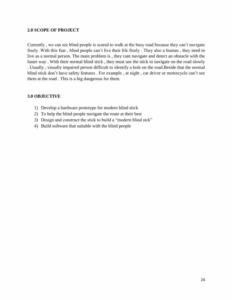
2.0 SCOPE OF PROJECT
Currently , we can see blind people is scared to walk at the busy road because they can’t navigate
freely .With this fear , blind people can’t live their life freely . They also a human , they need to
live as a normal person. The main problem is , they cant navigate and detect an obstacle with the
faster way . With their normal blind stick , they must use the stick to navigate on the road slowly
. Usually , visually impaired person difficult to identify a hole on the road.Beside that the normal
blind stick don’t have safety features . For example , at night , car driver or motorcycle can’t see
them at the road . This is a big dangerous for them.
3.0 OBJECTIVE
1) Develop a hardware prototype for modern blind stick
2) To help the blind people navigate the route at their best
3) Design and construct the stick to build a “modern blind stck”
4) Build software that suitable with the blind people

25
METHODOLOGY
FLOWCHART :
BLOCK DIAGRAM
YES NO NO
YES
START
Ultrasonic Sensor
Ultrasonic sensor
detect a hole
Distance <15
Ultrasonic Triggered
Source code in Arduino
run
Buzzer will beeping and
vibration motor will
vibrate
GSM & GPS on
GSM waits for the
request
Request Valid
GPS On (Get the coordinates)
GSM get the data and send
Users receive the data
END
26
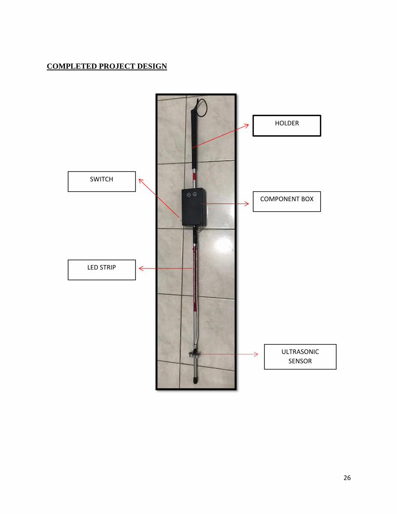
COMPLETED PROJECT DESIGN
LED STRIP
ULTRASONIC
SENSOR
COMPONENT BOX
SWITCH
HOLDER
27
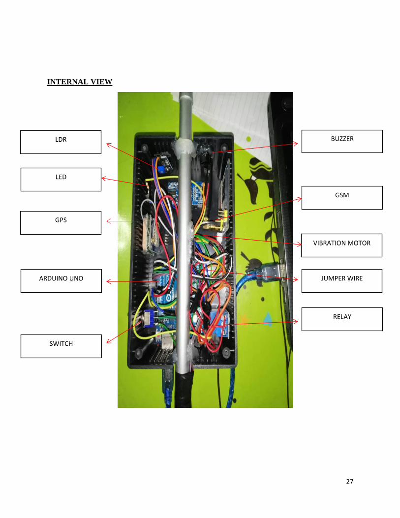
INTERNAL VIEW
GPS
GSM
ARDUINO UNO
LDR
RELAY
SWITCH
BUZZER
VIBRATION MOTOR
LED
JUMPER WIRE
28
LIST OF COMPONENT USED
1. Arduino uno
The Arduino Uno is an open-source microcontroller board based on the Microchip
ATmega328P microcontroller and developed by Arduino.cc.The board is equipped with
sets of digital and analog input/output (I/O) pins that may be interfaced to various
expansion boards (shields) and other circuits.[1] The board has 14 digital I/O pins (six
capable of PWM output), 6 analog I/O pins, and is programmable with the Arduino IDE
(Integrated Development Environment), via a type B USB cable. It can be powered by the
USB cable or by an external 9-volt battery, though it accepts voltages between 7 and 20
volts. It is also similar to the Arduino Nano and Leonardo.The hardware reference design
is distributed under a Creative Commons Attribution Share-Alike 2.5 license and is
available on the Arduino website. Layout and production files for some versions of the
hardware are also available.
2. Ultrasonic Sensor
As the name indicates, ultrasonic sensors measure distance by using ultrasonic waves.
The sensor head emits an ultrasonic wave and receives the wave reflected back from the
target. Ultrasonic Sensors measure the distance to the target by measuring the time between
the emission and reception.
3. GPS
The Global Positioning System (GPS), originally NAVSTAR GPS,is a satellite-based
radionavigation system owned by the United States government and operated by the United
States Space Force It is one of the global navigation satellite systems (GNSS) that provides
geolocation and time information to a GPS receiver anywhere on or near the Earth where
there is an unobstructed line of sight to four or more GPS satellites.Obstacles such as
mountains and buildings block the relatively weak GPS signals.
4. GSM
The Global System for Mobile Communications (GSM) is a standard developed by the
European Telecommunications Standards Institute (ETSI) to describe the protocols for
second-generation (2G) digital cellular networks used by mobile devices such as mobile
phones and tablets. It was first deployed in Finland in December 1991.[2] By the mid-
2010s, it became a global standard for mobile communications achieving over 90% market
share, and operating in over 193 countries and territories.
29
5. Buzzer
A buzzer or beeper is an audio signalling device,[1] which may be mechanical,
electromechanical, or piezoelectric (piezo for short). Typical uses of buzzers and beepers
include alarm devices, timers, and confirmation of user input such as a mouse click or
keystroke.
6. LED
A light-emitting diode (LED) is a semiconductor light source that emits light when current
flows through it. Electrons in the semiconductor recombine with electron holes, releasing
energy in the form of photons. The color of the light (corresponding to the energy of the
photons) is determined by the energy required for electrons to cross the band gap of the
semiconductor.[5] White light is obtained by using multiple semiconductors or a layer of
light-emitting phosphor on the semiconductor device
7. Switch
In electrical engineering, a switch is an electrical component that can disconnect or connect
the conducting path in an electrical circuit, interrupting the electric current or diverting it
from one conductor to another.[1][2] The most common type of switch is an
electromechanical device consisting of one or more sets of movable electrical contacts
connected to external circuits. When a pair of contacts is touching current can pass between
them, while when the contacts are separated no current can flow.
8. LDR
A photoresistor (acronymed LDR for Light Decreasing Resistance, or light-dependent
resistor, or photo-conductive cell) is an active component that decreases resistance with
respect to receiving luminosity (light) on the component's sensitive surface. The resistance
of a photoresistor decreases with increase in incident light intensity
30
LITERATURE REVIEW
STATISTICS :
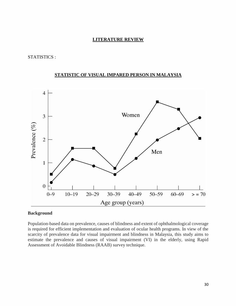
STATISTIC OF VISUAL IMPARED PERSON IN MALAYSIA
Background
Population-based data on prevalence, causes of blindness and extent of ophthalmological coverage
is required for efficient implementation and evaluation of ocular health programs. In view of the
scarcity of prevalence data for visual impairment and blindness in Malaysia, this study aims to
estimate the prevalence and causes of visual impairment (VI) in the elderly, using Rapid
Assessment of Avoidable Blindness (RAAB) survey technique.
31
Methods
Malaysia was divided into six regions, with each region consisting of 50 clusters. Multistage
cluster sampling method was used and each cluster contained 50 residents aged 50 years and above.
Eligible subjects were interviewed and pertinent demographic details, barriers to cataract surgery,
medical and ocular history was noted. Subjects had visual acuity assessment with tumbling ‘E’
Snellen optotypes and ocular examination with direct ophthalmoscope. The primary cause of VI
was documented. Results were calculated for individual zones and weighted average was used to
obtain overall prevalence for the country. Inter-regional and overall prevalence for blindness,
severe VI and moderate VI were determined. Causes of VI, cataract surgical coverage and barriers
to cataract surgery were assessed.
Results
A total of 15,000 subjects were examined with a response rate of 95.3%. The age and gender-
adjusted prevalence of blindness, severe visual impairment and moderate visual impairment were
1.2% (95% Confidence Interval: 1.0–1.4%), 1.0% (95%CI: 0.8–1.2%) and 5.9% (5.3–6.5%)
respectively. Untreated cataract (58.6%), diabetic retinopathy (10.4%) and glaucoma (6.6%) were
the commonest causes of blindness. Overall, 86.3% of the causes of blindness were avoidable.
Cataract surgical coverage (CSC) in persons for blindness, severe visual impairment and moderate
visual impairment was 90%, 86% and 66% respectively.
32
CONCLUSSION
We conclude that our project are useful to the visually impaired person and family or guardian that
have visually impaired kids. This project help the visually impaired person to walk at the public
more easily and safely . With our safety features, we can reduces the risk of the visually impaired
walk in public. Therefore, we creating this project is to help the visually impaired person to live
as a normal person.
REFFERENCE
1) https://journals.plos.org/plosone/article?id=10.1371/journal.pone.0198799
2) http://www.ghrnet.org/index.php/IJOR/article/view/2068/2425
3) https://en.wikipedia.org/wiki/Photoresistor
4) https://en.wikipedia.org/wiki/Switch
5) https://en.wikipedia.org/wiki/Light-emitting_diode