Embed Size (px)
Citation preview
Modern Digital Switch Subscriber Loop Block Diagram
Subscriber Line Interface Card/Chip (SLIC) Some BORSCHT Explanations Digital Switch Advantages
Page 3
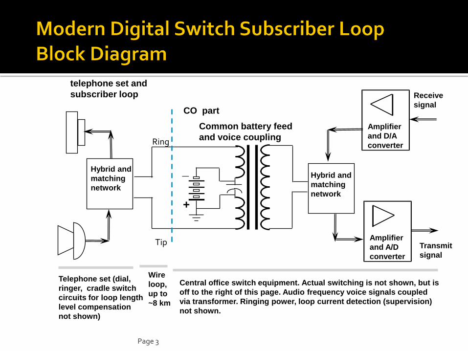
Hybrid and
matching
network
Hybrid and
matching
network
_
+
Telephone set (dial,
ringer, cradle switch
circuits for loop length
level compensation
not shown)
Wire
loop,
up to
~8 km
Central office switch equipment. Actual switching is not shown, but is
off to the right of this page. Audio frequency voice signals coupled
via transformer. Ringing power, loop current detection (supervision)
not shown.
Amplifier
and A/D
converter
Amplifier
and D/A
converter
Transmit
signal
Receive
signal CO part
telephone set and
subscriber loop
Common battery feed
and voice coupling
Tip
Ring
Page 4
Due to large volume of use, integrated circuits are available which perform most of these BORSCHT functions
ICs designed for line card in switch and chips for use in a low-cost telephone set are both available
Spoken acronym SLIC /slIk/ sounds like another acronym, Subscriber Line Concentrator (SLC). Ask for fully spelled out version if context is not clear!
Page 5
Battery Feed via split winding on audio coupling transformer
Over-voltage (lighting, power line crossing) protection primarily based on arc-over at spark gaps installed where outdoor wiring enters subscriber premises and CO building. Enclosed gas spark gaps provide uniform electrical “breakdown” at ~300 volts
between wires or wire-to-ground
▪ Hermetic enclosure prevents variations due to air pressure and humidity, a problem in older lightning arrestor devices
Non-linear series resistance devices limit high current surges due to lightning or accidental “cross” with power voltage wiring
▪ Light bulbs or “heat coils”
▪ Positive Temperature Coefficient (PTC) resistors using conductive polymer plastics
Not on subscriber loop circuit card, except for PTC resistor.
Page 6
Ringing voltage from ringing generator via electro-mechanical relay contacts on tip & ring
Supervision (dc loop current sensing) via various methods: Sensing relay coil in series with subscriber loop. Loop current actuates separate
relay contacts.
▪ Inductance of relay coil affects frequency response somewhat, but can be bypassed for audio frequencies via a capacitor
Non-linear magnetic material (“saturable magnetic core”) with loop current coil and sensing coil
▪ Loop current changes magnetization point behavior
▪ Sensing coil’s small signal inductance decreases when loop current is on.
▪ Smaller, less costly, less effect on voice signal.
Page 7
CODEC (COder/DECoder) in switch (except for ISDN sets):
Low pass filter the audio on analog side of A/D conversion
▪ Active RC filter, switched capacitor filter, or CCD (charge control diode array) transversal filter are different analog technologies
▪ Purpose is to attenuate audio power above about 3.5 kHz
Then “measure” voltage, 8000 samples/second for coding
Encode each voltage sample as a compressed digitally coded 8 bit sign-magnitude binary code
▪ Mu-law approximately logarithmic compression rule used in North America and Japan
▪ A-law log-linear compression rule used in other national PSTN systems
Digital/Analog conversion in opposite direction as well Hybrid or directional coupler is analog device using multiple windings on transformers,
together with a “matching network” composed of resistors and capacitors
Separates incoming and outgoing electrical waveforms on 2-wire subscriber loop into separate unidirectional signals with good but not perfect accuracy
All digital transmission operations in a digital switch comprise two opposite-flowing unidirectional signal paths
Page 8
Electro-mechanical relay installed in the line card can switch subscriber loop temporarily to an auxiliary test device
Main test operation is to measure (tiny) microamperes of “leakage” current between wires and from each wire to ground ▪ High leakage current indicates imminent failure due to moisture in cable, damaged insulation,
etc.
Testing is usually done circa 2 AM when traffic is minimal
▪ Even so, if subscriber lifts handset or a call comes in, test is suspended until loop is again idle
Suspicious test results are automatically reported to repair crafts persons
▪ Tremendous reduction in staff is feasible when their repair work can be scheduled, rather than waiting for an emergency, unexpected customer complaint, or loop failure!
▪ Most repairs are thus done before customer notices noisy line problems!
▪ Consequently, most unexpected failures today are due to human error or accident, rather than slow cable deterioration
Page 9
Automatic test reduces staff costs significantly
Predominant cost saving in many cases!! Feature-rich, increases income of public telephone
company by selling optional “vertical” features (e.g. Call waiting, conference, etc.)
Inter-works with digital trunks (T-1 etc.) without use of channel banks
Smaller size allows more CO capacity growth in same building
Less electric power consumption, reduces operating costs somewhat
Page 10
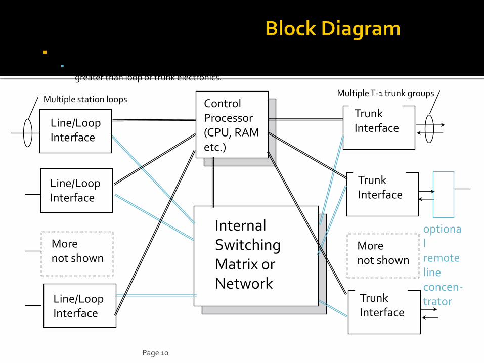
Internal Switching Matrix or Network
Control Processor and Switching Matrix are duplicated for reliability
Line and trunk interface cards are not duplicated because failure rate on outside plan wiring is greater than loop or trunk electronics.
Internal Switching Matrix or Network
Line/Loop Interface
Trunk Interface
Control Processor (CPU, RAM etc.)
Line/Loop Interface
Line/Loop Interface
Trunk Interface
Trunk Interface
More not shown
More not shown
Multiple station loops Multiple T-1 trunk groups
optional remote line concen- trator
Page 11
Each end office switch has at least 3 translation tables in its control processor 1. Internal line appearance number (ILAN) translated to directory number (DN)
▪ Identifies billing number for originated calls, and for calling line ID
▪ ILAN is a proprietary number indicating the rack, shelf and circuit card number of a line
2. Inverse table of above: DN to ILAN
▪ Used to route incoming call to proper destination line
3. Translates from NPA/NXX (or just NXX) into the proper outgoing trunk group to reach that destination.
Two inverse tables are used for fast look-up Like using both a Spanish-English and a separate English-Spanish dictionary for
human language ‘translation’
Tiny switches (example: 16 lines) use just one table and perform exhaustive search for the “inverse” translation function
Additions, removals, and changes in DNs are made by entries in these tables, not by rewiring the external subscriber loops.
Page 12
A switch can be configured with only trunk interfaces (no line interfaces). Applications include everything except traditional end central office use: Tandem or transit switch use in local or long-distance network
A cellular or Personal Communication System (PCS) radio system switch
▪ Connections to base radio stations are via trunks (e.g., T-1)
Historically, a switch can be configured with only line interfaces (no trunks) for use as an “intercom” or PAX inside a building. Seldom installed today since a standard PBX with both inside and outside connections is less costly than “two track” systems.
A line module can be located remote from the switch location when a distant cluster of subscribers needs service.
▪ Connects to main switch via T-1 links thru a trunk interface
▪ Subscriber Line Concentrator (SLC-96) is an example of this.
▪ PBX also performs this function, but has different signaling and is typically subscriber owned. PBX and SLC systems are not covered here In detail.