Embed Size (px)
Citation preview

4-l
Chapter 4 Modes of Gas Turbine Component Life Consumption
bY (C. Eady)
Page
1. Introduction
2. Gas Turbine Engine Failure Mechanisms
2.1. Mechanical Fatigue 2.1.1. Low Cycle Fatigue
2.2. High Cycle Fatigue (HCF) 2.2.1. Engine Configuration 2.2.2. Intake Effects 2.2.3. Out of Balance
2.3. Thermo-Mechanical Fatigue
2.4. Creep 2.4.1. Stress Rupture
2.5. Corrosion 2.5.1. Corrosion Fatigue
2.6. Erosion
2.7. Fretting, Galling and Wear
3. External Causes of Life Consumption 3.1. Manufacturing and Material Defects
3.1.1. Components not to Drawing 3.1.2. Manufacturing Process Control 3.1.3. Surface Conditioning 3.1.4. Stress-Raisers
3.2. Build or Maintenance Errors
3.3. Foreign Object Damage 3.3.1. Limit Exceedance
4-3
4-3
4-3 4-4
4-5 4-5 4-6 4-6 4-6
4-7 4-7
4-7 4-8 4-8
4-9
4-10
4-10 4-10 4-10 4-10 4-11
4-11 4-11 4-11
4. Summary 4-12
5. References 4-12


4-3
1. INTRODUCTION
In this chapter the main failure modes of mechanical components are shown in pictures of real components, and described in simple physical terms.
Critical components, for which safe operating lives are defined, include the major rotating parts, the turbo- machinery disks and shafts, and structural casings subjected to high loads. In addition to the major components, other components in the rotating assemblies, such as spacers, cover-plates and seals, may also be designated as critical. To avoid unacceptable risk of catastrophic failure it is necessary to monitor the life usage of critical components and retire them from service before their allocated life has been exceeded.
under the control of engine manufacturers, operators and maintainers, they could be described as avoidable. In reality, however, this is difficult to achieve.
The accuracy of the process for determining safe component life and the monitoring of its consumption may have a major impact upon the safety of the engine or on its life cycle cost. Engine design-features and operational environments that most undermine safety or are most costly, financially or in maintenance effort, must be identified. Only then can managers assess the potential benefit of proposed modifications to the design or changes to operating practices. Even minor changes to operating practice, which may have little or no operational impact, can significantly lower life usage rates and bring the benefits of higher availability and reduced life cycle cost.
A thorough understanding of the failure mechanisms Monitoring systems can only monitor phenomena that affecting gas turbine components is essential if the failure they can detect and measure. Therefore, great care is modes, the safe-life, and the life usage of each component required during the design and introduction of any system, are to be accurately determined and safely monitored. to ensure that it meets the needs of people at all levels in Those failure mechanisms are: the operator’s organisation.
Low cycle fatigue; High cycle fatigue; Thermo-mechanical fatigue; Creep; Overstress; Corrosion; Erosion; Fretting and Wear.
2.1. MECHANICAL FATIGUE
In most practical aerospace engineering situations, the applied stresses are not steady. Instead, the loading fluctuates, often in a random manner. Under conditions of cyclic stress, it is frequently found that failure occurs at lower stress levels than would be expected, were a steady stress applied. This phenomenon is fatigue and causes the vast majority of in-service failures.
The ability of a component to resist the effects of any of these failure mechanisms is a function of the material properties, the component design and the operating environment. These features of the component are effectively fixed by the design and application of the following 3 phases:
The process of fatigue is usually divided into the
engine and cannot be affected by the way in which the engine is operated or maintained. As such the chosen engine cycle, its configuration and the selected operating environment may be considered to be intrinsic factors which impact on the rate of component life usage. Conversely, there are external factors which also have an influence on the rate of component life consumption but which can be reduced during engine manufacture, operation and maintenance. Best maintenance practice, no matter how good, can at best only
2. GAS TURBINE ENGINE FAILURE MECHANISMS
Crack Propagation (Striations)
Overload Zone
Figure 1 - Characteristic fatigue fracture
Crack ini (Nucleati
.tiation
.on)
c . . . . Crack initiation (primary stage); restore component and system pertormance to me levels . that were intrinsic to the original design.
Crack propagation (secondary stage); . Unstable crack propagation (tertiary stage).
The external factors affecting life usage rate are:
. Manufacturing and material defects; Figure 1 shows the features of a characteristic fatigue fracture. The number of stress cycles to failure is
. Build and maintenance errors; dependent upon the material type, component processing,
. Foreign Object Damage (FOD); load history, design, and the degree of loading. . Limit exceedances. Since these four engine damage sources are effectively The fatigue behaviour of a material is normally plotted on

4-4
an S-N graph. Here S is the average stress range applied (in simple harmonic motion), and N the number of cycles to failure, at that combination of mean stress and stress range. Fatigue failure is a statistical phenomenon and accurate measurement of the fatigue properties of a material requires a large number of tests to ascertain the failure probability distribution at each applied mean stress and fluctuating stress amplitude. A characteristic S-N plot for zero mean stress, showing the mean failure curve and the failure distributions, is given in figure 2.
Component fatigue life is not only dependent upon the choice of material and the magnitude of the mean and
Figure 2 - S-N diagram.
cyclic stresses. Materials production and processing can have a significant impact on component performance in service. Microstructural variables such as changes in grain size, alloying and the presence of non- metallic inclusions will affect the fatigue life. Fatigue behaviour is also very sensitive to:
. Random stress fluctuations;
. Stress concentrations;
. Surface finish;
. Residual stresses;
. Corrosive environments,
The effect of the above factors is that severe fatigue life penalties can be imposed through inadequate component design or inappropriate material selection for a given operating environment.
Figure 3 - Fatigue crack growth
The design loads for gas turbine components are mainly in the elastic region of the stress/strain curve of the material. In some cases, cyclic softening can cause highly localised plastic deformation. This happens when high stress concentrations cause yielding, which then reduces the local stress to levels where yielding no longer occurs,
The traditional approach to fatigue, for which the S-N curve was designed, chiefly concerned itself with failure after a large number of cycles. At higher stresses and lower cycles, the fatigue life reduces progressively and the scale of the plastic deformation creates difficulty in interpreting test results. In this region of Low Cycle Fatigue (LCF), sometimes termed high-strain fatigue, the materials tests are based on constant strain cycling rather than constant stress cycling.
the number of times that a cyclic load is applied that is of particular importance. Rather the amount of damage accumulated during each application of the load. For critical gas-turbine components, it is appropriate to differentiate between LCF and HCF by identifying the driver of the cyclic loading. LCF is typically driven by pilot demands and the application of relatively large loads whereas HCF is typically driven by sources of vibration and the application of relatively small loads.
2.1.1. Low CYCLE FATIGUE
The transition point from LCF to High Cycle Fatigue (HCF) is generally assumed to occur where the total strain comprises equal proportions of elastic and plastic strain. However, for convenience, LCF is often considered to lead to failure in less than lo5 cycles and HCF to lead to failure after more than 10’ cycles. The intermediate range may be considered to fall into either region, depending on the design application. It must be remembered that it is not
If the amplitude of the cyclic stresses applied to a component is very high (LCF), the accumulated strain energy per reversal will be significantly higher than for an HCF loading cycle. For this reason, under LCF, a component will spend a very small proportion of its life in the primary, crack initiation stage and the majority of its life in the secondary, crack propagation phase of fatigue failure. As a result, since crack initiation is often governed by random imperfections in the microstructure, the scatter in LCF data is lower than that for HCF data, as can be seen in figure 2. Under such high loading, it is also

4-5
possible that plastic deformation around a concentration each time they pass. The passing frequency depends upon feature will redistribute (‘shake down’) the stress to a less the number of obstructions and the rotational speed of the damaging amplitude and leave the component under stage. For example, each blade on a turbine assembly
rotating at 19406 RPM behind a set of 34 nozzle guide residual compressive stress whilst stationary.
Most of the critical components within gas- turbine engines, the turbo-machinery disks and shafts, and pressure vessels such as the combustion chamber outer casing, are subjected to very high loading cycles and are, therefore, life limited by LCF. The mechanical loading on these components is caused by:
. Centrifugal forces and thermal loads on the disks;
. Torsion and bending forces on the shafts;
. High pressures within the casings;
. Thermal gradients within components
The cyclic nature of these forces is due to variations in engine power setting. One complete, or major, cycle is experienced when the engine is accelerated from standstill to maximum engine rotational speed and then returned to standstill. Minor cycles of varying size are experienced for all other throttle movements. LCF for a gas turbine can therefore be characterised as loading cycles ;ure 4 - Fatigue crack growth l- Fig caused by variations in rotational speed, temperature distribution in parts, or engine internal pressure, which are most often due to throttle movement. The appearance of typical LCF failures is shown in figures 3,4 and 5.
2.2. HIGH CYCLE FATIGUE (HCF)
Fatigue failure occurs when either the material fracture toughness is exceeded by the combination of applied stress and crack size, or a critical crack size is attained in a highly stressed region of a component. The process to achieve either of these conditions involves crack initiation and sub-critical crack propagation. Whilst components under an LCF regime spend the majority of their lives in the crack propagation phase, for HCF, crack initiation often tends to be the time-consuming process. Low amplitude, high frequency loading cycles (HCF) could quickly propagate a LCF initiated crack to failure.
HCF is primarily a function of engine design. A Figure 5 - Fatigue failure in an LP blade attachment lug
comnonent that fails in HCF does so because it has been vanes will experience 39.6 million loading cycles per L
subjected to a large number (> IO’) of stress cycles (where hour. It is, therefore, important that the stress amplitude is
compressor blades are subjected to high cycle very small so that the blades are operating below the
aerodynamic loading this is known as flutter). A number fatigue limit set by the curve in figure 2.
of factors can cause high frequency loading of components. These are generally known as drivers and
Campbell Spoke Diagrams are used to identify regions
their causes are listed below. where problems might occur. A blade design has its natural frequency calculated or measured. Corrections are
2.2.1. ENGINE CONFIGURATION applied to account for a natural frequency drop due to temoerature rise and the stiffening effect due to radial
The layout of the engine itself is the cause of many HCF A ’ centrrfugal forces. The overall effect is usually for the drivers. The presence of both upstream and downstream natural frequency of the blade to rise as engine speed obstructions in the gas path can create perturbations in the increases. flow that will cause the turbo-machinery blades to deflect
4-6
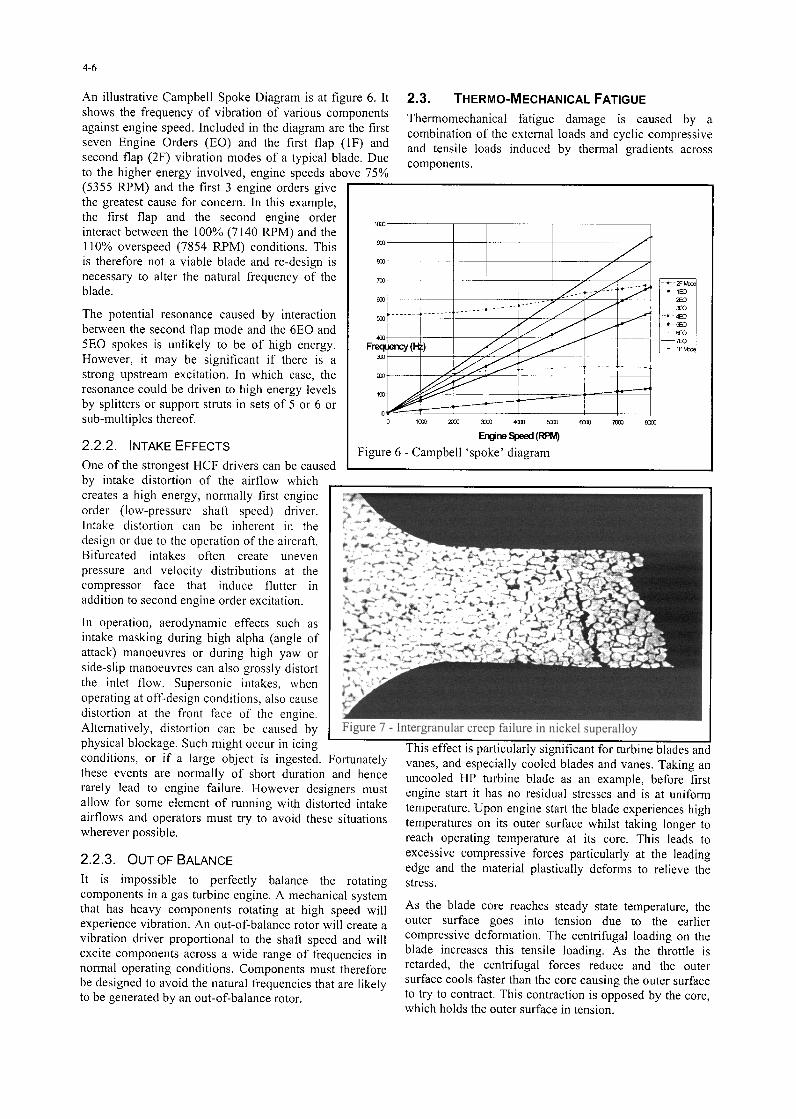
An illustrative Campbell Spoke Diagram is at figure 6. It 2.3. THERMO-MECHANICAL FATIGUE shows the frequency of vibration of various components against engine speed. Included in the diagram are the first
Thermomechanical fatigue damage is caused by a
seven Engine Orders (EO) and the first flap (1F) and combination of the external loads and cyclic compressive
second flap (2F) vibration modes of a typical blade. Due and tensile loads induced by thermal gradients across
to the higher energy involved, engine speeds above 75% components.
(5355 RPM) and the first 3 engine orders give the greatest cause for concern. In this example, the first flap and the second engine order interact between the 100% (7140 RPM) and the
um I
110% overspeed (7854 RPM) conditions. This is therefore not a viable blade and re-design is necessary to alter the natural frequency of the blade.
The potential resonance caused by interaction between the second flap mode and the 6E0 and 5E0 spokes is unlikely to be of high energy. However, it may be significant if there is a strong upstream excitation. In which case, the resonance could be driven to high energy levels by splitters or support struts in sets of 5 or 6 or sub-multiples thereof.
2.2.2. INTAKE EFFECTS
One of the strongest HCF drivers can be caused
F
Figure 6 - Campbell ‘spoke’ diagram
by intake distortion of the airflow which creates a high energy, normally first engine order (low-pressure shaft speed) driver. Intake distortion can be inherent in the design or due to the operation of the aircraft. Bifurcated intakes often create uneven pressure and velocity distributions at the compressor face that induce flutter in addition to second engine order excitation.
In operation, aerodynamic effects such as intake masking during high alpha (angle of attack) manoeuvres or during high yaw or side-slip manoeuvres can also grossly distort the inlet flow. Supersonic intakes, when operating at off-design conditions, also cause distortion at the front face of the engine. Alternatively, distortion can be caused by physical blockage. Such might occur in icing conditions, or if a large object is ingested. Fortunately these events are normally of short duration and hence rarely lead to engine failure. However designers must allow for some element of running with distorted intake airflows and operators must try to avoid these situations wherever possible.
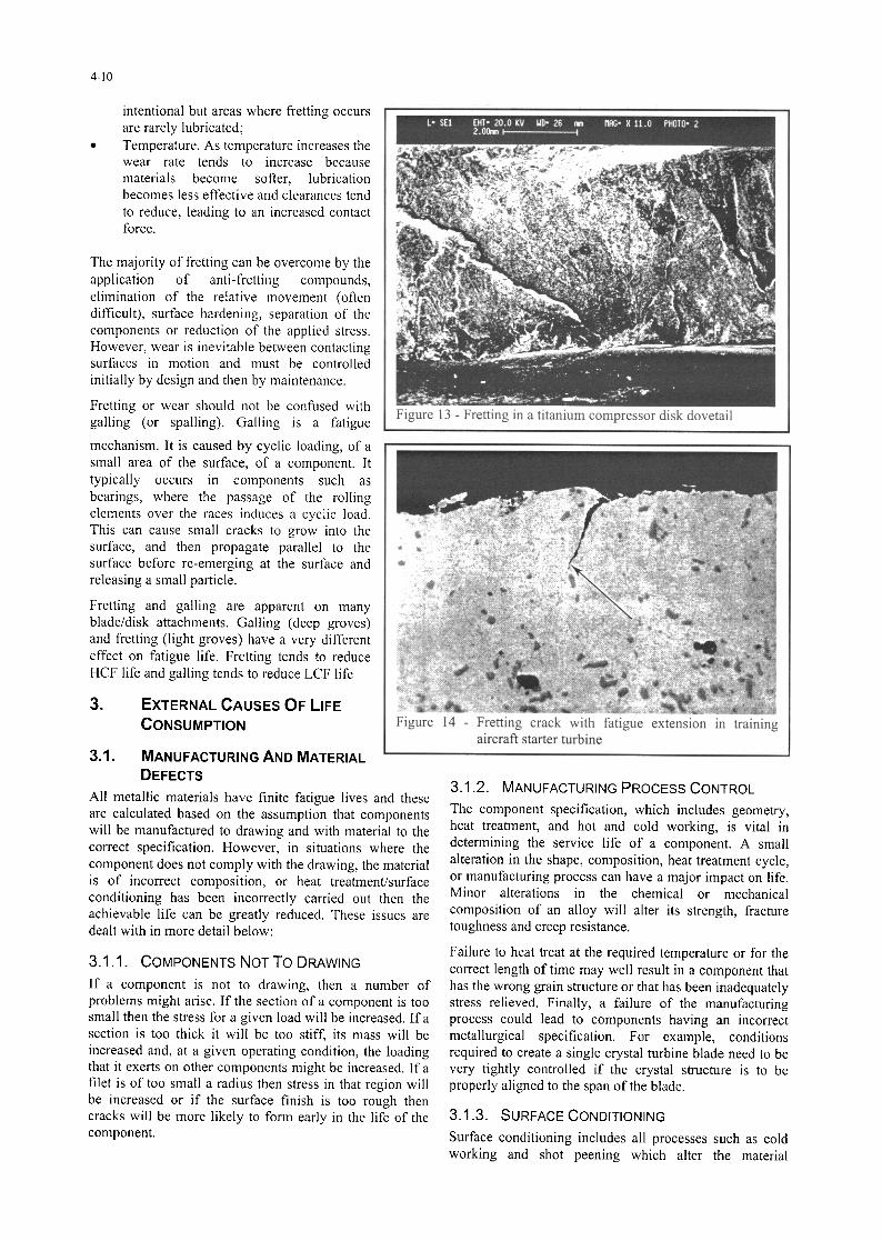
Figure 7 - Intergranular creep failure in nickel superalloy
2.2.3. OUT OF BALANCE
It is impossible to perfectly balance the rotating components in a gas turbine engine. A mechanical system that has heavy components rotating at high speed will experience vibration. An out-of-balance rotor will create a vibration driver proportional to the shaft speed and will excite components across a wide range of frequencies in normal operating conditions. Components must therefore be designed to avoid the natural frequencies that are likely to be generated by an out-of-balance rotor.
This effect is particularly significant for turbine blades an vanes, and especially cooled blades and vanes. Taking an uncooled HP turbine blade as an example, before first engine start it has no residual stresses and is at uniform temperature. Upon engine start the blade experiences high temperatures on its outer surface whilst taking longer to reach operating temperature at its core. This leads to excessive compressive forces particularly at the leading edge and the material plastically deforms to relieve the stress.
As the blade core reaches steady state temperature, the outer surface goes into tension due to the earlier compressive deformation. The centrifugal loading on the blade increases this tensile loading. As the throttle is retarded, the centrifugal forces reduce and the outer surface cools faster than the core causing the outer surface to try to contract. This contraction is opposed by the core, which holds the outer surface in tension.

When the engine is shutdown and reaches the ambient temperature throughout, there remains a tensile stress in the outer surface of many components. This process enhances the level of tensile stress cycling experienced by the blade, particularly in the thinner sections such as the leading and trailing edges, where temperature changes occur most rapidly.
It can therefore be seen that the blade goes through a stress sequence with every change of temperature. The scale of the load imposed is proportional to the temperature gradient induced in the blade and this is a function of the rate of throttle movement. Therefore, for long engine life throttle movements should be made as slowly as possible.
Thrust producing engines, such as turbo-jets or turbo-fans, operate at varying speeds and temperatures. The thermal and mechanical load cycles tend to happen simultaneously. However, since the thermal loading
4-l
forms part of the total extension reached in a given time and so affects the choice of clearances.
. The Secondary Stage shows creep occurring at a relatively constant rate; this is the important part of the curve for most applications.
. The Tertiary Stage shows an acceleration of the creep rate to failure; this stage should be avoided in operation but the transition from the Secondary Stage to the Tertiary can be difficult to predict.
2.4.1. STRESS RUPTURE For design purposes, so-called stress rupture curves are used to simplify creep modelling. These are obtained by measuring the time to failure of a specimen under constant load and temperature conditions. The curves are simply a plot of the log of time to failure against temperature for various loads. The result is usually a straight line and this representation simplifies the calculations.
affects the degree of mechanical loading, engine life usage counters really need Thermal Transient Algorithms (TTA) in order to most accurately monitor fatigue life consumption.
Some torque producing engines such as turbo-props and turbo-shafts, may have one shaft running at constant speed whilst the temperature varies. In such cases, the mechanical load cycles are easily monitored. On the other hand, changes in torque demand are achieved by altering engine- running temperature. Hence, thermal fatigue effects predominate and must be monitored, to ensure safe and efficient engine operation.
Log time
Figure 8 - The three stages of creep
For critical components such as turbo- machinery disks, the transient thermal effects may only be significant during major throttle modulations. However, the disks do suffer a temperature gradient from bore to rim. This gradient is usually a cooler bore to a hotter rim, especially for turbines and the HP sections of compressors, but it may go the other way for LP compressors with anti-icing air or balancing air within the shaft. Whichever way the thermal gradient operates, it will also effect material properties. The thermal gradient will produce a stress field that varies across the radius due to the temperature differences and the coefficient of expansion.
2.5. CORROSION Irreversible damage can be caused to engine components in aggressive environments. Corrosive elements can be introduced to the engine in the fuel (eg sulphur) and in the inlet airflow (eg airborne pollutants or sodium chloride from marine environments).
2.4. CREEP Creep is a time-dependent inelastic deformation of metals and alloys, which occurs under stress, at temperatures above about 0.5 of the melting point temperature. The higher the temperature and the greater the load, the faster will be the rate of deformation. In a gas turbine the components which suffer most from creep are the hot parts of turbine disks and the turbine blades. However, blades tend to fail due to impact with adjacent rows or casings rather than purely due to creep. Figure 7 shows a typical failure.
Corrosion can be controlled through careful selection of materials, the application of coatings, and the maintenance of the surface finish throughout the life of the engine. Regular water washing after each sortie, if necessary, should be considered for engines operated in corrosive atmospheres.
Corrosion may reduce the life of an aero engine in 3 ways.
Figure 8 shows the three stages of creep.
. The Primary Stage depicts rapid extension at a decreasing rate; this is of interest to the designer as it
. By reducing the load bearing area. Corrosion causes loss of material, and can weaken a component so much that it fails under normal loading. Corrosion on this scale is usually easy to detect during routine inspection. Much more difficult to detect is a small corrosion pit that acts as a stress raiser hence causing a premature LCF or HCF failure. Any breakdown in sealing effectiveness within the turbine section may also permit hot gas ingress to the disk void areas and result in material degradation.
. By reducing aerodynamic efficiency. If aerodynamic surfaces, particularly blades and vanes and to a lesser extent walls and diffusers, suffer corrosion

4-8
they are roughened. The effect of this is to alter the nature of the airflow over them and hence reduce their efficiency. Any reduction in efficiency of the turbo-machinery will result in a loss of thrust at a given cycle temperature or require that temperature to be raised to maintain thrust. In either event, the life of the engine will be reduced due to premature rejection for low thrust or excessive operating temperature.
. By causing a blockage. With aluminium based materials, the products of corrosion can occupy six times the volume of the non-corroded material. Therefore, in extreme cases, the corrosion will result in severe restrictions to cooling passages and possible bursting of thin-walled sections. The disruption of cooling flows may also cause hot spots to develop and lead to early creep failure.
Although corrosive action can remove enough material to directly affect the performance of a component, the mechanical integrity of high strength components is likely to be jeopardised long before any visible evidence of corrosive attack. This is due to the creation of sites from which fatigue cracks can propagate. Examples of the effects of corrosion are shown in figures 9, 10 and 11.
2.51. CORROSION FATIGUE The response of different alloys to combined stress and corrosion varies greatly but those that fail usually do so without any gross corrosion. When there is a combination of a corrosive environment and a fluctuating stress, a hazardous condition described as corrosion fatigue can occur. The effect of corrosion fatigue is usually to reduce the fatigue life much more severely than would be expected by the separate consideration of the two mechanisms.
The first stage of corrosion fatigue is usually pitting of the surface layer of the material. This weakening allows micro cracks to form and the second stage establishes corrosion in these cracks. In this way, both the crack initiation phase and the propagation phase of fatigue failure are accelerated by the corrosive process as good material is removed and the cracks are wedged with the products of corrosion. Electrolysis at a crack tip may cause atomic hydrogen, which can penetrate the metal lattice and cause hydrogen embrittlement. This may further accelerate crack growth.
2.6. EROSION Erosion is the cumulative damage to components in the airstream caused by small hard particles carried in the gas path. What differentiates erosion from any other damage mechanism is the scale and nature of each individual damage event. Individually each event is inconsequential in terms of performance loss or reduction in mechanical strength. However, when very many events take place at one particular area of a component then the performance or strength of that component can be severely compromised. Erosion is often most apparent in compressors, particularly those used in
aircraft that routinely operate in dusty/sandy conditions. Helicopter engines are the worst affected, since by their very nature, they are prone to operate in dust clouds generated by the rotor downwash.
The typical effects of erosion within a gas-turbine engine are:
. To remove material from the rotor tips increasing tip clearance and reducing performance;
. To remove material from the leading edge of turbine blades as shown in figure 12;
. To reduce the chord width of the blades thus reducing aerodynamic performance.
Figure 9 - Salt corrosion of PT blade of aero- derivative gas turbine in marine environment
1 Figure 10 - Corrosion in nickel sunerallov

. Due to the vulnerability of helicopter engines to erosion, many are fitted with inlet particle separators, which, at the cost of some engine performance, remove many of the potentially eroding particles from the air before they reach the compressor. Both helicopter engines and turbo-fan engines in aircraft that fly low over the sea suffer from erosion due to the continual impact of salt crystals on the leading edges of fan and compressor blades.
Erosion rate is a function of the following. . Operating environment; . Component materials; . Design; . Protective coatings.
Figure 11 - Corrosion and spalling of thermal barrier coating in marine gas turbine caused by poor combustion
Predominately, erosion by inlet-airborne material is a compressor problem but it also affects other components in the airstream such as those in the by-pass duct. As particulates pass through the compressor, they are graded and the finer elements may be drawn into the cooling system. Not only does this process erode the internal air-washed parts, but it may lead to the glassification of sand particles in the turbine. When this happens molten silica solidifies on suitably ‘cooler’ surfaces, impedes cooling flows and may cause component failure due to overheating.
Particulates are frequently generated within the engine from:
. Erosion of abradable seal coatings by rotor blades;
. Hard carbon produced in the combustion section.
Although the critical components are not generally affected by the particulates carried in the mainstream flow, carry-through of hard particles into the cooling passages will remove material, particularly surface treatments, exposing the parent metal to corrosion.
2.7. FRETTING, GALLING AND WEAR
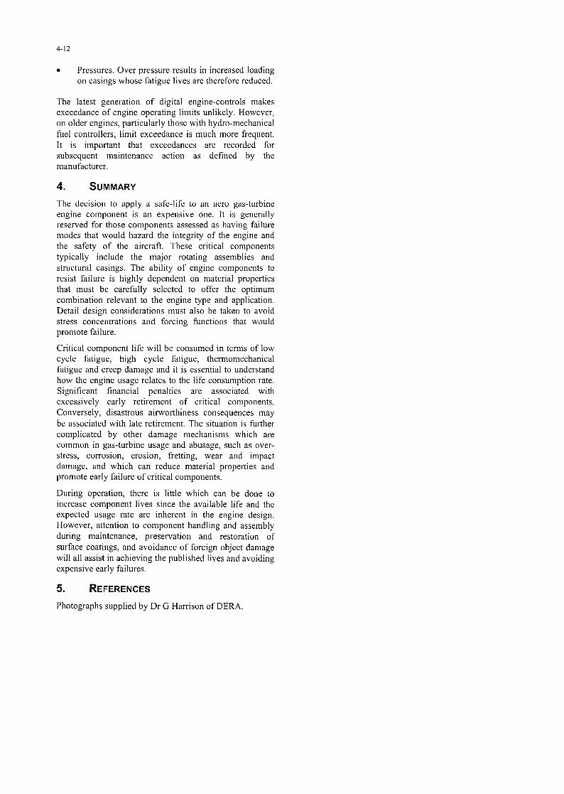
There are two sources of damage to contacting surfaces: fretting and wear. Fretting, shown magnified in figure 13, is due to oscillatory motion of very small amplitude, much smaller than may occur with normal wear. This can occur in joints that are bolted, keyed, press fitted, shrunk or riveted. Fretting also affects splines, couplings, clutches, spindles and seals. The effects of fretting are accelerated because the debris produced is trapped at the wear site and, whilst it may not lead to component failure, fretting produces small surface cracks which can propagate to a conventional fatigue failure. The start of such a crack is shown in figure 14.
Figure 12 - Erosion of marine GT PT blade due to carbon in the gas stream from poor combustion
Wear will occur whenever two or more contacting components experience relative motion. Unlike fretting, wear is the result of large scale, unavoidable movement between two components. Typical examples of wear include a piston in the bore of an actuator, bearings, air and oil seals, and blade tips on abradable seals. The rate of wear is determined by a number of factors:
. Relative hardness of contacting materials. The softer material will wear more rapidly;
. Contact force. The higher the contact-force, the greater the wear rate;
. Lubrication. Lubrication is normally provided to control wear in components where relative motion is
4-10
intentional but areas where fretting occurs are rarely lubricated;
. Temperature. As temperature increases the wear rate tends to increase because materials become softer, lubrication becomes less effective and clearances tend to reduce, leading to an increased contact force.
The majority of fretting can be overcome by the application of anti-fretting compounds, elimination of the relative movement (often difficult), surface hardening, separation of the components or reduction of the applied stress. However, wear is inevitable between contacting surfaces in motion and must be controlled initially by design and then by maintenance.
Fretting or wear should not be confused with galling (or spalling). Galling is a fatigue
mechanism. It is caused by cyclic loading, of a small area of the surface, of a component. It typically occurs in components such as bearings, where the passage of the rolling elements over the races induces a cyclic load. This can cause small cracks to grow into the surface, and then propagate parallel to the surface before re-emerging at the surface and releasing a small particle.
Figure 13 - Fretting in a titanium compressor disk dovetail
Fretting and galling are apparent on many blade/disk attachments. Galling (deep groves) and fretting (light groves) have a very different effect on fatigue life. Fretting tends to reduce HCF life and galling tends to reduce LCF life
3. EXTERNAL CAUSES OF LIFE CONSUMPTION
3.1. MANUFACTURING AND MATERIAL DEFECTS
Figure 14 - Fretting crack with fatigue extension in training aircraft starter turbine
All metallic materials have finite fatigue lives and these 3.1.2. MANUFACTURING PROCESS CONTROL
are calculated based on the assumption that components The component specification, which includes geometry,
will be manufactured to drawing and with material to the heat treatment, and hot and cold working, is vital in
correct specification. However, in situations where the determining the service life of a component. A small
component does not comply with the drawing, the material alteration in the shape, composition, heat treatment cycle,
is of incorrect composition, or heat treatment/surface or manufacturing process can have a major impact on life.
conditioning has been incorrectly carried out then the Minor alterations in the chemical or mechanical
achievable life can be greatly reduced. These issues are composition of an alloy will alter its strength, fracture
dealt with in more detail below: toughness and creep resistance.
3.1 .I. COMPONENTS NOT To DRAWING
If a component is not to drawing, then a number of problems might arise. If the section of a component is too small then the stress for a given load will be increased. If a section is too thick it will be too stiff, its mass will be increased and, at a given operating condition, the loading that it exerts on other components might be increased. If a filet is of too small a radius then stress in that region will be increased or if the surface finish is too rough then cracks will be more likely to form early in the life of the component.
Failure to heat treat at the required temperature or for the correct length of time may well result in a component that has the wrong grain structure or that has been inadequately stress relieved. Finally, a failure of the manufacturing process could lead to components having an incorrect metallurgical specification. For example, conditions required to create a single crystal turbine blade need to be very tightly controlled if the crystal structure is to be properly aligned to the span of the blade.
3.1.3. SURFACE CONDITIONING
Surface conditioning includes all processes such as cold working and shot peening which alter the material

4-11
properties of the surface of the material. Most commonly, in gas turbine components, surface conditioning is used to impart a residual compressive stress into the surface of the component in areas where cracks are most likely to form. The effect of this is to inhibit crack initiation and thus extend life. If the chosen technique is not carried out sufficiently then the full benefit is not achieved. If it is over done then the surface can become excessively work hardened and brittle, or sub-surface tensile stresses may be generated, making it more prone to cracking.
. Use of reverse thrust;
. Helicopter downwash;
. Inlet vortices.
There are other ways in which FOD can occur:
3.1.4. STRESS-RAISERS
Stress-raisers are features at the surface of, or embedded within, a component that cause stress contours to deviate from their normal (design) orientation, parallel to the direction of load, and to intensify around the tip of the feature. This is shown at figure 15. At the tip of the feature, in this case shown as a notch in the surface, there is a high stress concentration. The fatigue life will therefore be much reduced and a crack will start to propagate from this point.
. Objects left in intakes during maintenance;
. Objects, particularly fasteners, from either the parent aircraft or an aircraft in close formation, typically during air-to-air refuelling;
. Bird ingestion;
. Ice ingestion.
Helicopters, due to their downwash and operation from unprepared sites, and combat aircraft, due to high specific thrust, low by-pass ratios and intake positioning, are worst affected by FOD.
Once damage is caused it will fall into one of these categories:
Stress-raisers can be caused in a large number of ways.
. They can be present at manufacture as inclusions in the metal melt;
. Tools can leave scratches during machining; Lack of care during transport, storage or handling.
3.2. BUILD OR MAINTENANCE ERRORS
One of the most effective ways to shorten the life of an engine right from the beginning is to build it incorrectly. Many mistakes can be made during the build or maintenance of an aero-engine. Some of these are listed below.
. Acceptable with no maintenance necessary;
. Acceptable but only after the damaged component has been blended or cropped to remove a stress raiser;
. Unacceptable, either the damaged blade will have to be changed in-situ, where this is possible, or the engine will have to be removed for repair;
. Catastrophic, leading to in-flight loss of an engine. This occasionally happens when aerodynamically induced blade flutter causes crack initiation and a HCF blade failure occurs.
Whatever the category of the FOD it may reduce the life of the engine. Even if acceptable, it will contribute to performance loss or cumulative damage and hence premature engine rejection.
3.3.1. LIMIT EXCEEDANCE
Typical limit exceedances are listed below.
. Incorrect tolerances;
. Incorrect clearances;
. Incorrect torque loading;
. Insufficient cleanliness leading to blocked oil ways or dirt in bearings;
. Failure to apply lubricants; .
. Incorrect assembly;
. Incorrect adjustment.
All of these can, and have, led to reduced engine life through early component failure or performance loss. All ’ build and maintenance errors are avoidable but still occur regularly.
3.3. FOREIGN OBJECT DAMAGE
Foreign Object Damage (FOD) is an inevitable part of engine operations. Gas turbines have a high air mass-flow- rate and loose articles that are close to the intake of the engine are likely to be ingested. A gas turbine is able to lift objects from the ground in some circumstances. However, ingestion is much more likely to occur when a particle is already in motion. This motion can be due to a number of factors the most common of which are listed below.
.
. Jet efflux of another aircraft;
. Thrown up by aircraft wheels;
. High winds;
Absolute Temperature. Any exceedance of a temperature limit will result in life being consumed at a greater than planned rate. An exceedance of an absolute temperature limit may result in damage to the turbine and/or combustion section. Time at Temperature. Most engines have temperature settings (ratings) that should only be used for limited periods. These include take-off, climb, combat, and emergency limits. The stress rupture life of the turbine blades will have been calculated on the assumption that these limits will not be exceeded. The longer the time spent at these elevated temperatures and hence rotational speeds (in the case of turbo-jets, turbo-fans and turbo-prop gas generators) the greater will be the rate of creep life consumption. It should be noted that current generation FADECs do not prevent time-at- temperature limits being exceeded. Rotational speeds. Whilst engines are designed to survive overspeeds of up to 122’33, lifing calculations are based on speed limits being observed. Therefore, overspeeds result in increased dynamic loads that consume fatigue and creep life at a very high rate.
4-12
. Pressures. Over pressure results in increased loading on casings whose fatigue lives are therefore reduced.
The latest generation of digital engine-controls makes exceedance of engine operating limits unlikely. However, on older engines, particularly those with hydro-mechanical fuel controllers, limit exceedance is much more frequent. It is important that exceedances are recorded for subsequent maintenance action as defined by the manufacturer.
4. SUMMARY
The decision to apply a safe-life to an aero gas-turbine engine component is an expensive one. It is generally reserved for those components assessed as having failure modes that would hazard the integrity of the engine and the safety of the aircraft. These critical components typically include the major rotating assemblies and structural casings. The ability of engine components to resist failure is highly dependent on material properties that must be carefully selected to offer the optimum combination relevant to the engine type and application. Detail design considerations must also be taken to avoid stress concentrations and forcing functions that would promote failure.
Critical component life will be consumed in terms of low cycle fatigue, high cycle fatigue, thermomechanical fatigue and creep damage and it is essential to understand how the engine usage relates to the life consumption rate. Significant financial penalties are associated with excessively early retirement of critical components. Conversely, disastrous airworthiness consequences may be associated with late retirement. The situation is further complicated by other damage mechanisms which are common in gas-turbine usage and abusage, such as over- stress, corrosion, erosion, fretting, wear and impact damage, and which can reduce material properties and promote early failure of critical components.
During operation, there is little which can be done to increase component lives since the available life and the expected usage rate are inherent in the engine design. However, attention to component handling and assembly during maintenance, preservation and restoration of surface coatings, and avoidance of foreign object damage will all assist in achieving the published lives and avoiding expensive early failures.
5. REFERENCES
Photographs supplied by Dr G Harrison of DERA.