Embed Size (px)
Citation preview

MODIFICATION OF STRESS INTENSITY FACTOR EQUATION FOR CORNER
CRACKS FROM A HOLE UNDER REMOTE BENDING
W. Zhao and J. C. Newman, Jr.
April 1996
The stress intensity factor equations for several typical crack configurations and loading
conditions, developed by Newman and Raju [1-3], have been widely used in various damage
tolerance analyses, and combined into a number of popular computer programs for life prediction
of fatigue crack propagation. These equations greatly facilitate the damage tolerance analysis by
not only providing the stress intensity factor solutions in a closed form, but also extending the
solutions beyond the range in which the finite element solutions were available.
All the equations have been used successfully with one exception: small comer cracks (a/t
< 0.2) emanating from a hole under remote bending [3]. Figure 1 shows the configuration in
question and the definition of related parameters to be used. A recent study using a
three-dimensional weight function method [4], which provides independent solutions for comer
cracks emanating from a hole, has shown that significant error in the equation exists for small
comer cracks under remote bending. The reason for the loss of accuracy was an invalid
assumption made on the limiting behavior as alt -+ O. Figure 2 shows an example of comparisons
between the equation [3] and the weight function solutions [4]. It is noted that, at the time of the
equation development [1-3], many engineering judgments and assumptions were necessary
1
because available solutions were far from sufficient for developing equations, especially for small
comer cracks from a hole subjected to remote bending.
The objective of the present work is to improve the accuracy of the bending equation for
comer cracks emanating from holes [3] using a modification based on the weight function
solutions [4]. The modifications are carried out in such a way that the change in the functional
form of the original equation [3] will be kept to a minimum. The applicable range of the modified
equation will stay the same as before.
The nomenclature in [3] is followed and given below for convenience.
a, c = semi-axes of a quarter-elliptical crack
b = half plate width
Fch = dimensionless stress intensity factor for comer crack at a hole under bending
h = half plate height
Hch = bending multiplier for comer crack at a hole
K = stress intensity factor
Q = shape factor of an ellipse
r = hole radius
Sb = remote outer fiber bending stress, 3M/b/e
St = remote tensile stress
t = plate thickness
2
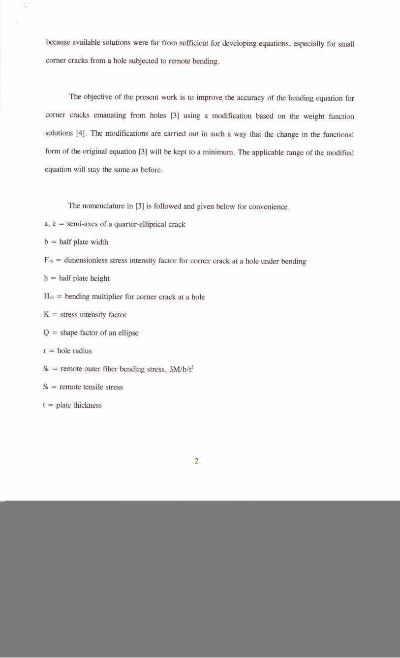
<p = parametric angle of an elliptical crack
To start with, the original equation [3] is listed in the following.
K = (SI + HchSb).J1mIQ FCh(al c, alt, r It, rib, c I b, ¢)
For alc :s;1:
aM/ = 1.13 - 0.09
c
M2 = -0.54 + 0.890.2+!!.
c
M3=0.5- 1 +14(1-ay,0.65 + !!.- c
c
g/ = 1+[0.1 +0.35(a /](1-sin¢/t
3
(1)
(3) S
(5)5
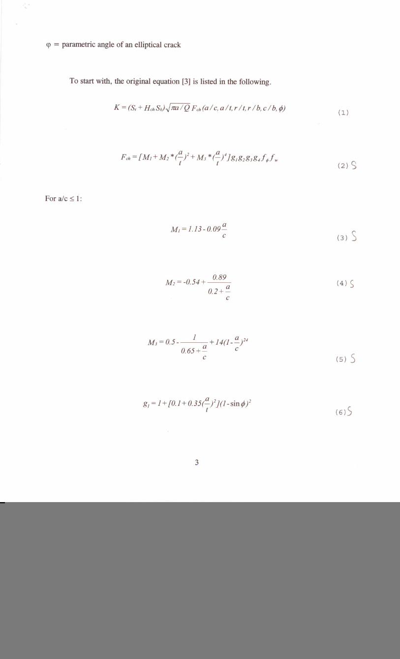
1+ 0.358)" + 1.425).,2 -1.578).,3 + 2.156 X'
g2 = 1+ 0.13 ).,2
).,= 11+ (c Ir) cos{[0.85 - 0.25(a Itf25JrftJ
g3 = (1+ 0.04 a)[1 + 0.1 (1- cosrft/J[0.85 + 0.15(a f25Jc t
a a ag-/ = 1- O.7(1--)(-- 0.2)(1--)
tee
f¢ = [(a I c/ cos2 rft+sin2rft/25
fw = (sec(1U')sec[ 7r(2r + nc) ra 0.52b 4(b-c) + 2nc VtJJ
4
(8) S
(10) 5
(12) 5
(13) 5ct~ 5
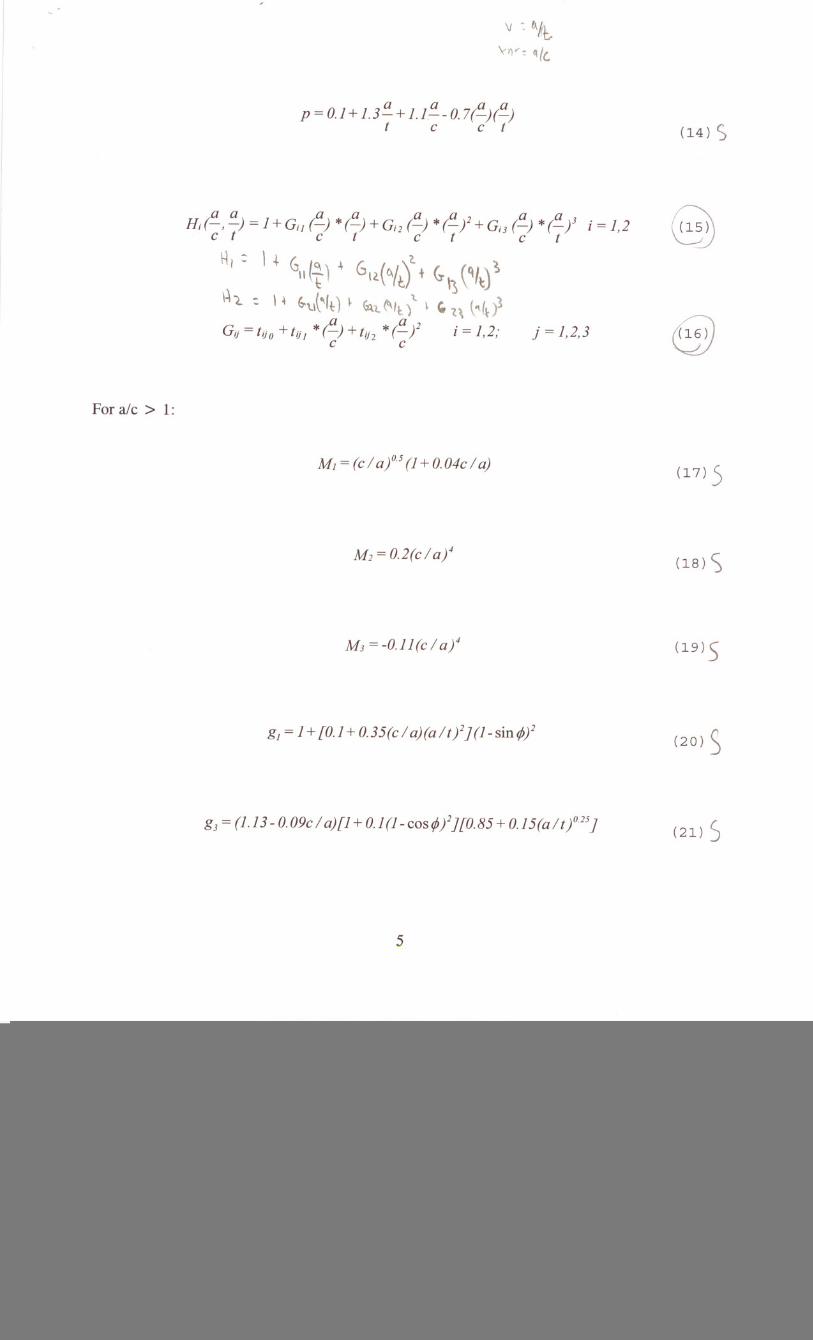
For ale> 1:
V : fJ..h•.
\-IV: q(c.
a a a ap = 0.1 + 1.3'- + 1.I--O.7(-) (-)
tee t
i = 1,2
j = 1,2,3
M, = (c I af5 (1+ 0.04c I a)
M2 = 0.2(c I a/,
M3 = -0.11 (c I a/,
g, = 1+ [0.1 + 0.35(c I aHa It/](1-sinrjJ/
g3 = (1.13 - 0.09c I a)[1 + 0.1 (1- cas rjJ/][O.85 + 0.15(a Itf25]
5
(14) S
(17) 5
(18) S
(19) 5
(20) S
(21) S

f¢ = [(e / a/ sin2¢+ cos2¢/25
e ap = 0.2+-+ 0.6 *(-)
a t
(22) 5
(23) 5
(24) 5
i = 1,2; j = 1,2,3
Equation (1) shows that the bending solution is obtained by combining a bending
multiplier, Hch, with the tension solution, Fch. (For tension, all the equations related to Fchwill be
the same as shown here, with only one exception of eq.(8).) Thus, of interest to the present work
are the equations (13)-(16), (24) and (25), among which eqs.(15), (16) and (25) are necessary to
modify .
It is also noted that the above bending related equations do not contain rlt as a variable in
them, which implies that rlt has the same effect on bending solution as it does on tension.
However, the weight function solutions [4] show that it is helpful to introduce rlt into the bending
related equations. This is achieved by introducing two fine-tuning functions, It (i= 1,2), into the
Hi functions.
6

Without going into the detail, the modified equations are given below, using the same
equation numbers with an Im I attached.
i = 1,2; j = 0,1,2,3 (16m)
The fine tuning functions in eq.(l5m) are:
i = 1,2; j = 0,1,2,3 (25m)
(R1)
(R1)
Though the same functional form is used in the modified equation, attention should be paid to
eq.(25m), in which the variable is ale, instead of cia as in eq.(25). The coefficients in eqs.(l6m)and
7
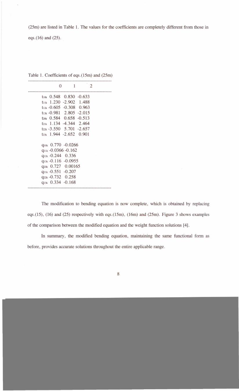
(25m) are listed in Table 1. The values for the coefficients are completely different from those in
eqs.(16) and (25).
Table 1. Coefficients of eqs.(15m) and (25m)
o 1 2
tlOk0.548 0.830 -0.633tllk 1.230 -2.902 1.488tl2k-0.605 -0.308 0.963t13k-0.981 2.805 -2.015t:20k0.584 0.658 -0.513t:21k1.134 -4.344 2.464U2k-3.550 5.701 -2.657t:23k1.944 -2.652 0.901
qlOk0.770 -0.0266qllk -0.0366 -0.162ql2k-0.244 0.336ql3k-0.116 -0.0955q20k0.727 0.00165q2lk-0.551 -0.207q22k-0.732 0.258q23k0.334 -0.168
The modification to bending equation is now complete, which is obtained by replacing
eqs.(15), (16) and (25) respectively with eqs.(15m), (16m) and (25m). Figure 3 shows examples
of the comparison between the modified equation and the weight function solutions [4].
In summary, the modified bending equation, maintaining the same functional form as
before, provides accurate solutions throughout the entire applicable range.
8
References
[1] J.e. Newman, Jr. and I.S. Raju, Analyses of surface cracks in finite plates under tension andbending loads. NASA TP-1578 (1979).
[2] J.C. Newman Jr.and I.S. Raju, Stress intensity factor equations for cracks in threedimensional finite bodies. ASTM STP 791,(Edited by J.C. Lewis and G. Sines), 1-238 1-256 (1983).
[3] J .C. Newman Jr.and I.S. Raju, Stress intensity factor equations for cracks in three-dimensional finite bodies subjected to tension and bending loads. in Computational Methodsin the Mechanics of Fracture, (Edited by S.N. Atluri), 312-334 (1986).
[4] W. Zhao, J.e. Newman, Jr., M.A. Sutton, X.R. Wu and K.N. Shivakumar, Analysis ofcomer cracks at hole by a 3-D weight function method with stresses from finite elementanalysis. NASA TM-II0144 (1995).
[5] I.S. Raju and J.e. Newman, Jr., Stress intensity factors for two symmetric comer cracks.ASTM STP 677, C.W. Smith, Ed., 411-430 (1979).
9