Embed Size (px)
Citation preview
SPECIFICATION SHEET
1009, rue du Parc IndustrielLévis (Québec) G6Z 1C5 CanadaTel.: 1-888-839-4624Fax.: 1-877-839-7057 [email protected]
2019-01Revision 2 PRINTED IN CANADA
© 2019 Contraste Lighting M.L. Inc. All rights reserved
Contrast Lighting M.L. Inc. reserves the right to make changes in specifications and/or to discontinue any product at any time without notice or obligation and will not be liable for any consequences resulting from the use of this publication.
Project
Notes
Fixture Type
Date
Modul-AimTM MOD1
PAGE 1/14
Modular Base Unit (Patent Pending)
DESCRIPTION
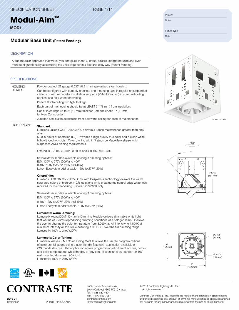
A true modular approach that will let you configure linear, L, cross, square, staggered units and even more configurations by assembling the units together in a fast and easy way (Patent Pending).
SPECIFICATIONS
HOUSING DETAILS
Powder coated, 22 gauge 0.036" (0.91 mm) galvanized steel housing. Can be configured with butterfly brackets and mounting bars in regular or suspended ceilings or with remodeler installation supports (Patent Pending) in standard ceiling applications only when renovating. Perfect fit into ceiling. No light leakage. Each part of the housing should be at LEAST 3" (76 mm) from insulation. Can fit in ceilings up to 2" (51 mm) thick for Remodeler and 1" (51 mm) for New Construction.Junction box is also accessible from below the ceiling for ease of maintenance.
LIGHT ENGINE Standard: Lumileds Luxeon CoB 1205 GEN3, delivers a lumen maintenance greater than 70% after50,000 hours of operation (L70). Provides a high quality true color and a clean white light without hot spots. Color binning within 3 steps on MacAdam ellipse which surpasses ANSI binning requirements.
Offered in 2,700K, 3,000K, 3,500K and 4,000K. 90+ CRI.
Several driver models available offering 3 dimming options: ELV: 120V to 277V (20W and 40W) 0-10V: 120V to 277V (20W and 40W)Lutron Ecosystem addressable: 120V to 277V (20W)
CrispWhite: Lumileds LUXEON CoB 1205 GEN2 with CrispWhite Technology delivers the warm saturated colors of high 90 + CRI solutions while creating the natural crisp whiteness required for merchandising. Offered in 3,000K only.
Several driver models available offering 3 dimming options: ELV: 120V to 277V (20W and 40W) 0-10V: 120V to 277V (20W and 40W)Lutron Ecosystem addressable: 120V to 277V (20W)
Lumenetix Warm Dimming: Lumenetix Araya DDM1 Dynamic Dimming Module delivers dimmable white light that warms as it dims reproducing dimming conditions of a halogen lamp. It allows the user to change the color temperature from 3,050K at full intensity to 1,800K at minimum intensity all this while ensuring a 90+ CRI over the full dimming range.Lumenetix: 100V to 240V (20W)
Lumenetix Color Tuning: Lumenetix Araya CTM1 Color Tuning Module allows the user to program millions of color combinations using a user friendly Bluetooth application available on iOS mobile devices. The application allows programming of different scenes, colors, and color temperatures while the day-to-day control is ensured by standard 0-10V wall mounted dimmers. 90+ CRI. Lumenetix: 100V to 240V (20W)
Ø 3-1/8"(79 mm)
Ø 4-1/2"(114 mm)
40°
7-9/16"(191 mm)
6"(152 mm)
6"(152 mm)
359°
MOD1-11XX-XXX
SPECIFICATION SHEET
1009, rue du Parc IndustrielLévis (Québec) G6Z 1C5 CanadaTel.: 1-888-839-4624Fax.: 1-877-839-7057 [email protected]
2019-01Revision 2 PRINTED IN CANADA
© 2019 Contraste Lighting M.L. Inc. All rights reserved
Contrast Lighting M.L. Inc. reserves the right to make changes in specifications and/or to discontinue any product at any time without notice or obligation and will not be liable for any consequences resulting from the use of this publication.
Modul-AimTM MOD1
SPECIFICATIONS (CONT’D)
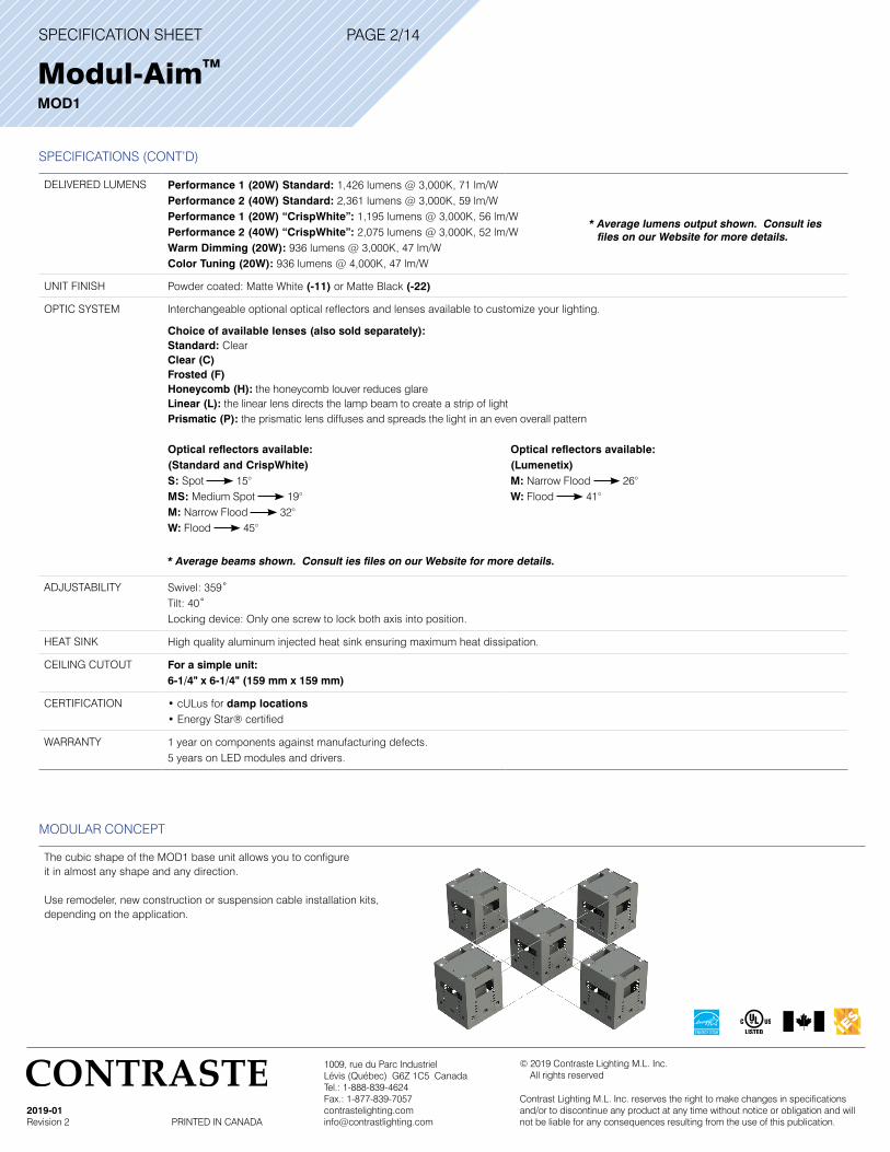
DELIVERED LUMENS Performance 1 (20W) Standard: 1,426 lumens @ 3,000K, 71 lm/WPerformance 2 (40W) Standard: 2,361 lumens @ 3,000K, 59 lm/WPerformance 1 (20W) “CrispWhite”: 1,195 lumens @ 3,000K, 56 lm/WPerformance 2 (40W) “CrispWhite”: 2,075 lumens @ 3,000K, 52 lm/WWarm Dimming (20W): 936 lumens @ 3,000K, 47 lm/WColor Tuning (20W): 936 lumens @ 4,000K, 47 lm/W
UNIT FINISH Powder coated: Matte White (-11) or Matte Black (-22)
OPTIC SYSTEM Interchangeable optional optical reflectors and lenses available to customize your lighting.
Choice of available lenses (also sold separately):Standard: ClearClear (C) Frosted (F) Honeycomb (H): the honeycomb louver reduces glare Linear (L): the linear lens directs the lamp beam to create a strip of light Prismatic (P): the prismatic lens diffuses and spreads the light in an even overall pattern
Optical reflectors available:(Standard and CrispWhite)S: Spot 15°MS: Medium Spot 19° M: Narrow Flood 32°W: Flood 45°
Optical reflectors available:(Lumenetix)M: Narrow Flood 26°W: Flood 41°
ADJUSTABILITY Swivel: 359˚Tilt: 40˚Locking device: Only one screw to lock both axis into position.
HEAT SINK High quality aluminum injected heat sink ensuring maximum heat dissipation.
CEILING CUTOUT For a simple unit: 6-1/4" x 6-1/4" (159 mm x 159 mm)
CERTIFICATION • cULus for damp locations• Energy Star® certified
WARRANTY 1 year on components against manufacturing defects.5 years on LED modules and drivers.
PAGE 2/14
MODULAR CONCEPT
The cubic shape of the MOD1 base unit allows you to configure it in almost any shape and any direction.
Use remodeler, new construction or suspension cable installation kits, depending on the application.
* Average lumens output shown. Consult ies files on our Website for more details.
* Average beams shown. Consult ies files on our Website for more details.
SPECIFICATION SHEET
1009, rue du Parc IndustrielLévis (Québec) G6Z 1C5 CanadaTel.: 1-888-839-4624Fax.: 1-877-839-7057 [email protected]
2019-01Revision 2 PRINTED IN CANADA
© 2019 Contraste Lighting M.L. Inc. All rights reserved
Contrast Lighting M.L. Inc. reserves the right to make changes in specifications and/or to discontinue any product at any time without notice or obligation and will not be liable for any consequences resulting from the use of this publication.
Modul-AimTM MOD1
PAGE 3/14
MODULAR CONCEPT (CONT’D)
General limitations • Maximum of 20 units per electrical circuit
• 8-1/2" clearance in height required in the ceiling
• Each unit weighs 5 pounds. Respect you national and local building codes regarding weight permitted in a ceiling
• Modul-Aim product configurator is available on our Website to help you calculate required installation kits based on your configuration
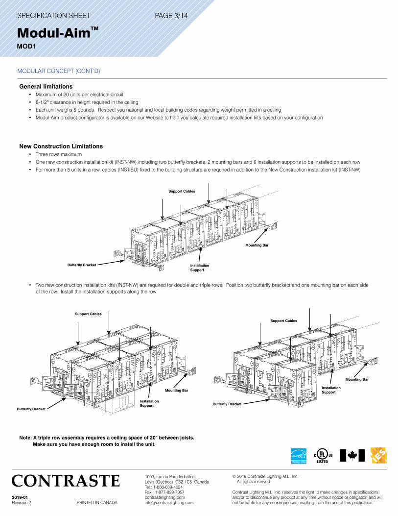
New Construction Limitations • Three rows maximum
• One new construction installation kit (INST-NW) including two butterfly brackets, 2 mounting bars and 6 installation supports to be installed on each row
• For more than 5 units in a row, cables (INST-SU) fixed to the building structure are required in addition to the New Construction installation kit (INST-NW)
• Two new construction installation kits (INST-NW) are required for double and triple rows. Position two butterfly brackets and one mounting bar on each side of the row. Install the installation supports along the row
Note: A triple row assembly requires a ceiling space of 20" between joists. Make sure you have enough room to install the unit.
Support Cables
Butterfly Bracket
Mounting Bar
Installation Support
Support Cables
Support Cables
Installation Support
Installation SupportMounting Bar
Mounting Bar
Butterfly BracketButterfly Bracket
SPECIFICATION SHEET
1009, rue du Parc IndustrielLévis (Québec) G6Z 1C5 CanadaTel.: 1-888-839-4624Fax.: 1-877-839-7057 [email protected]
2019-01Revision 2 PRINTED IN CANADA
© 2019 Contraste Lighting M.L. Inc. All rights reserved
Contrast Lighting M.L. Inc. reserves the right to make changes in specifications and/or to discontinue any product at any time without notice or obligation and will not be liable for any consequences resulting from the use of this publication.
Modul-AimTM MOD1
PAGE 4/14
MODULAR CONCEPT (CONT’D)
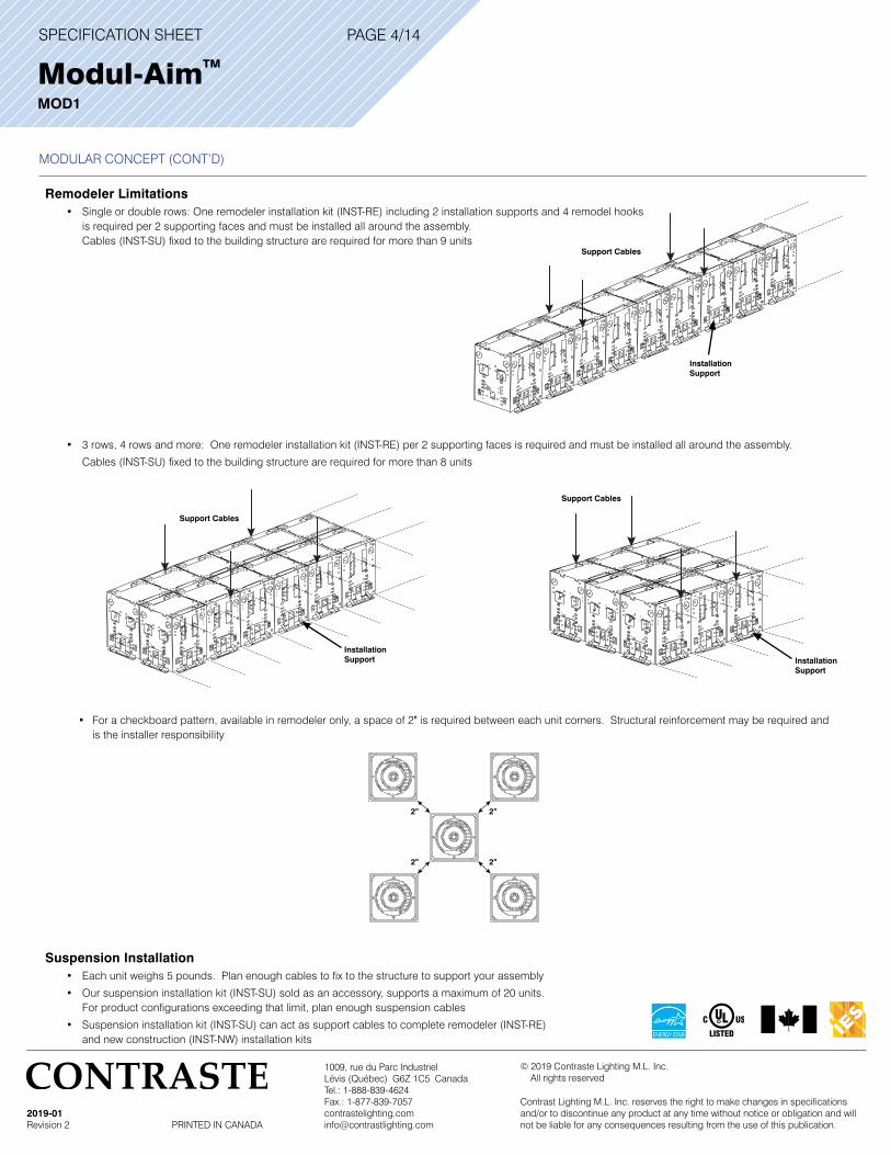
Remodeler Limitations • Single or double rows: One remodeler installation kit (INST-RE) including 2 installation supports and 4 remodel hooks is required per 2 supporting faces and must be installed all around the assembly. Cables (INST-SU) fixed to the building structure are required for more than 9 units
• 3 rows, 4 rows and more: One remodeler installation kit (INST-RE) per 2 supporting faces is required and must be installed all around the assembly.
Cables (INST-SU) fixed to the building structure are required for more than 8 units
• For a checkboard pattern, available in remodeler only, a space of 2" is required between each unit corners. Structural reinforcement may be required and is the installer responsibility
Suspension Installation • Each unit weighs 5 pounds. Plan enough cables to fix to the structure to support your assembly
• Our suspension installation kit (INST-SU) sold as an accessory, supports a maximum of 20 units. For product configurations exceeding that limit, plan enough suspension cables
• Suspension installation kit (INST-SU) can act as support cables to complete remodeler (INST-RE) and new construction (INST-NW) installation kits
Support Cables
Installation Support
Installation Support Installation
Support
Support Cables
Support Cables
2"2"
2"2"
SPECIFICATION SHEET
1009, rue du Parc IndustrielLévis (Québec) G6Z 1C5 CanadaTel.: 1-888-839-4624Fax.: 1-877-839-7057 [email protected]
2019-01Revision 2 PRINTED IN CANADA
© 2019 Contraste Lighting M.L. Inc. All rights reserved
Contrast Lighting M.L. Inc. reserves the right to make changes in specifications and/or to discontinue any product at any time without notice or obligation and will not be liable for any consequences resulting from the use of this publication.
Modul-AimTM MOD1
PAGE 5/14
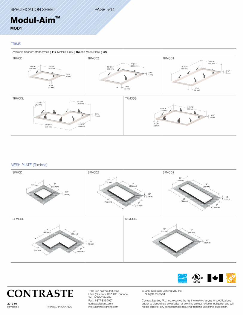
TRIMS
Available finishes: Matte White (-11), Metallic Grey (-15) and Matte Black (-22)
TRMOD1 TRMOD2 TRMOD3
TRMODL TRMODS
MESH PLATE (Trimless)
SFMOD1 SFMOD2 SFMOD3
SFMODL SFMODS
11"(279 mm) 6"
(154 mm)
1/2"(13 mm)
11"(279 mm) 12"
(306 mm)
17"(432 mm)
1/2"(13 mm)
6"(154 mm)
11"(279 mm)
18"(459 mm)
23"(584 mm)
1/2"(13 mm)
6"(154 mm)
17"(432 mm) 12"
(306 mm)
11"(279 mm)
1/2"(13 mm)
6"(154 mm)
17"(432 mm) 12"
(306 mm)
1/2"(13 mm)
3/16"(4 mm)
7-15/16"(202 mm)
19-15/16"(507 mm)
1-1/4"(32 mm)
3/16"(4 mm)
7-15/16"(202 mm)
13-15/16"(355 mm)
7-15/16"(202 mm)
13-15/16"(355 mm)
3/16"(4 mm)
13-15/16"(355 mm)13-15/16"
(355 mm)
1-1/4 "(32 mm)
3/16"(4 mm)
1-1/4"(32 mm)
7-15/16"(202 mm)
7-15/16"(202 mm)
7-15/16"(202 mm)13-15/16"
(355 mm)
3/16"(4 mm)
1-1/4"(32 mm)
SPECIFICATION SHEET
1009, rue du Parc IndustrielLévis (Québec) G6Z 1C5 CanadaTel.: 1-888-839-4624Fax.: 1-877-839-7057 [email protected]
2019-01Revision 2 PRINTED IN CANADA
© 2019 Contraste Lighting M.L. Inc. All rights reserved
Contrast Lighting M.L. Inc. reserves the right to make changes in specifications and/or to discontinue any product at any time without notice or obligation and will not be liable for any consequences resulting from the use of this publication.
Modul-AimTM MOD1
PAGE 6/14
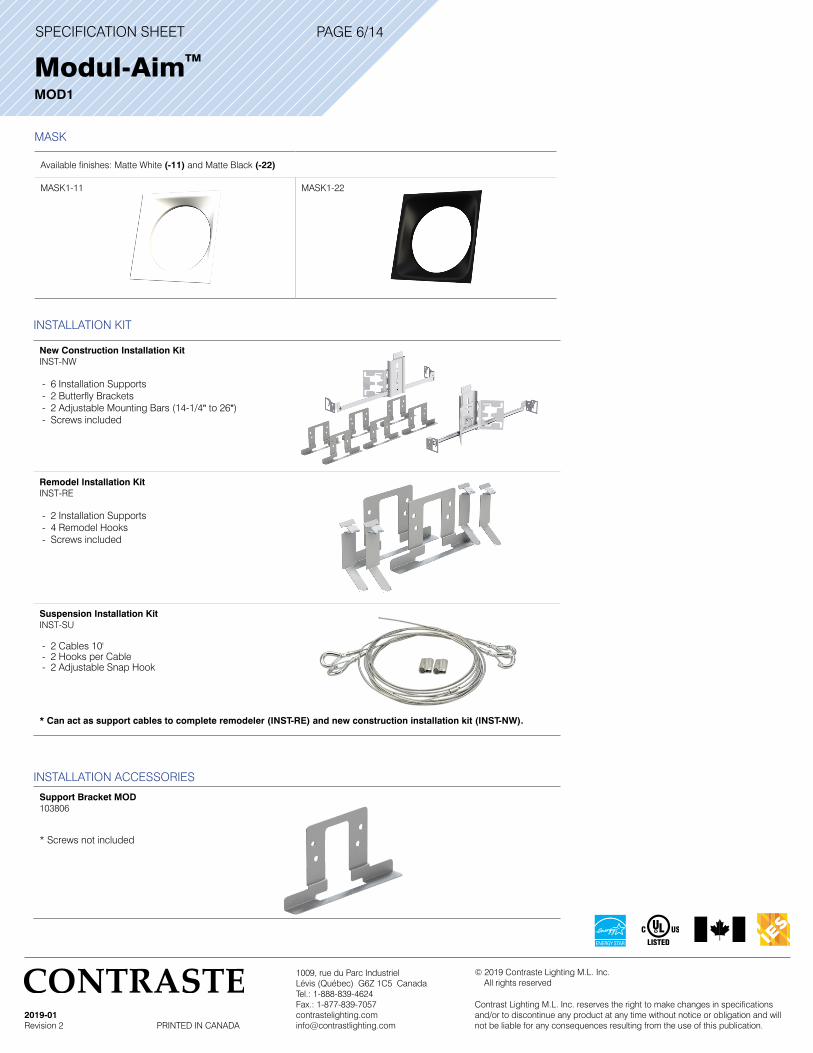
INSTALLATION KIT
New Construction Installation KitINST-NW
- 6 Installation Supports - 2 Butterfly Brackets - 2 Adjustable Mounting Bars (14-1/4" to 26") - Screws included
Remodel Installation KitINST-RE
- 2 Installation Supports - 4 Remodel Hooks - Screws included
Suspension Installation KitINST-SU
- 2 Cables 10' - 2 Hooks per Cable - 2 Adjustable Snap Hook
* Can act as support cables to complete remodeler (INST-RE) and new construction installation kit (INST-NW).
MASK
Available finishes: Matte White (-11) and Matte Black (-22)
MASK1-11 MASK1-22
INSTALLATION ACCESSORIES
Support Bracket MOD103806
* Screws not included

SPECIFICATION SHEET
1009, rue du Parc IndustrielLévis (Québec) G6Z 1C5 CanadaTel.: 1-888-839-4624Fax.: 1-877-839-7057 [email protected]
2019-01Revision 2 PRINTED IN CANADA
© 2019 Contraste Lighting M.L. Inc. All rights reserved
Contrast Lighting M.L. Inc. reserves the right to make changes in specifications and/or to discontinue any product at any time without notice or obligation and will not be liable for any consequences resulting from the use of this publication.
ORDERING CODES for Modular Base Unit with CrispWhite Technology
MODEL FINISHES DRIVER PERFORMANCE COLOR TEMPERATURES BEAMS CRISPWHITE
OPTION
MOD1 -30 -C
MOD1 Modular Base Unit -11
-22
Matte White
Matte Black
E
D
A
ELV
0-10V
Lutron Ecosystem Addressable
1
2
20W (1,195 Lumens delivered)
40W (2,075 Lumens delivered)
-30 3,000K S
MS
M
W
Spot 15°
Medium Spot 19°
Narrow Flood 32°
Flood 45°
-C CrispWhite Technology
Installation kits, trim, mask and trimless mesh plate to be ordered separately based on your configuration.
MODULAR BASE UNIT WITH CRISPWHITE TECHNOLOGY
CODIFICATION EXAMPLE
M O D 1 - 1 1 E 1 - 3 0 S - C
MODEL FINISH
DRIVER
PERFORMANCE
COLOR TEMPERATURE
BEAM
CRISPWHITE OPTION
PAGE 7/14
MODULAR BASE UNIT WITH STANDARD LIGHT ENGINE CODIFICATION EXAMPLE
M O D 1 - 1 1 E 2 - 3 5 S
MODEL FINISH
DRIVER COLOR TEMPERATURE
PERFORMANCEBEAM
ORDERING CODES for Modular Base Unit with Standard Light Engine
MODEL FINISHES DRIVER PERFORMANCE COLOR TEMPERATURES BEAMS
MOD1
MOD1 Modular Base Unit -11
-22
Matte White
Matte Black
E
D
A
ELV
0-10V
Lutron Ecosystem Addressable
1
2
20W (1,426 Lumens delivered)
40W (2,361 Lumens delivered)
-27
-30
-35
-40
2,700K
3,000K
3,500K
4,000K
S
MS
M
W
Spot 15°
Medium Spot 19°
Narrow Flood 32°
Flood 45°
Installation kits, trim, mask and trimless mesh plate to be ordered separately based on your configuration.
Modul-AimTM MOD1
(Available with Performance 1 only)
(Available with Performance 1 only)
SPECIFICATION SHEET
1009, rue du Parc IndustrielLévis (Québec) G6Z 1C5 CanadaTel.: 1-888-839-4624Fax.: 1-877-839-7057 [email protected]
2019-01Revision 2 PRINTED IN CANADA
© 2019 Contraste Lighting M.L. Inc. All rights reserved
Contrast Lighting M.L. Inc. reserves the right to make changes in specifications and/or to discontinue any product at any time without notice or obligation and will not be liable for any consequences resulting from the use of this publication.
PAGE 8/14
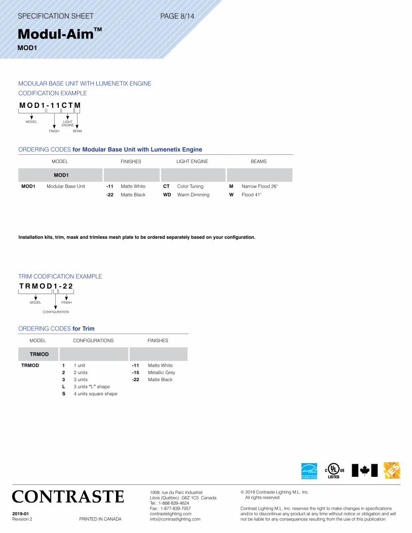
TRIM CODIFICATION EXAMPLE
T R M O D 1 - 2 2
MODEL
CONFIGURATION
FINISH
ORDERING CODES for Trim
MODEL CONFIGURATIONS FINISHES
TRMOD
TRMOD 1
2
3
L
S
1 unit
2 units
3 units
3 units “L” shape
4 units square shape
-11
-15
-22
Matte White
Metallic Grey
Matte Black
MODULAR BASE UNIT WITH LUMENETIX ENGINE
CODIFICATION EXAMPLE
ORDERING CODES for Modular Base Unit with Lumenetix Engine
MODEL FINISHES LIGHT ENGINE BEAMS
MOD1
MOD1 Modular Base Unit -11
-22
Matte White
Matte Black
CT
WD
Color Tuning
Warm Dimming
M
W
Narrow Flood 26°
Flood 41°
Installation kits, trim, mask and trimless mesh plate to be ordered separately based on your configuration.
M O D 1 - 1 1 C T M
MODEL
FINISH
LIGHT ENGINE
BEAM
Modul-AimTM MOD1
SPECIFICATION SHEET
1009, rue du Parc IndustrielLévis (Québec) G6Z 1C5 CanadaTel.: 1-888-839-4624Fax.: 1-877-839-7057 [email protected]
2019-01Revision 2 PRINTED IN CANADA
© 2019 Contraste Lighting M.L. Inc. All rights reserved
Contrast Lighting M.L. Inc. reserves the right to make changes in specifications and/or to discontinue any product at any time without notice or obligation and will not be liable for any consequences resulting from the use of this publication.
Modul-AimTM MOD1
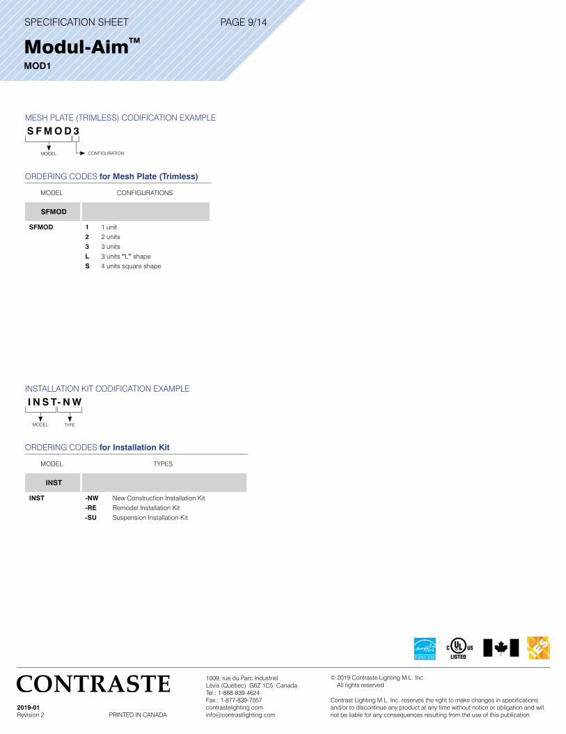
MESH PLATE (TRIMLESS) CODIFICATION EXAMPLE
S F M O D 3
MODEL CONFIGURATION
ORDERING CODES for Mesh Plate (Trimless)
MODEL CONFIGURATIONS
SFMOD
SFMOD 1
2
3
L
S
1 unit
2 units
3 units
3 units “L” shape
4 units square shape
INSTALLATION KIT CODIFICATION EXAMPLE
I N S T- N W
MODEL TYPE
ORDERING CODES for Installation Kit
MODEL TYPES
INST
INST -NW
-RE
-SU
New Construction Installation Kit
Remodel Installation Kit
Suspension Installation Kit
PAGE 9/14
SPECIFICATION SHEET
1009, rue du Parc IndustrielLévis (Québec) G6Z 1C5 CanadaTel.: 1-888-839-4624Fax.: 1-877-839-7057 [email protected]
2019-01Revision 2 PRINTED IN CANADA
© 2019 Contraste Lighting M.L. Inc. All rights reserved
Contrast Lighting M.L. Inc. reserves the right to make changes in specifications and/or to discontinue any product at any time without notice or obligation and will not be liable for any consequences resulting from the use of this publication.
Modul-AimTM MOD1
PAGE 10/14
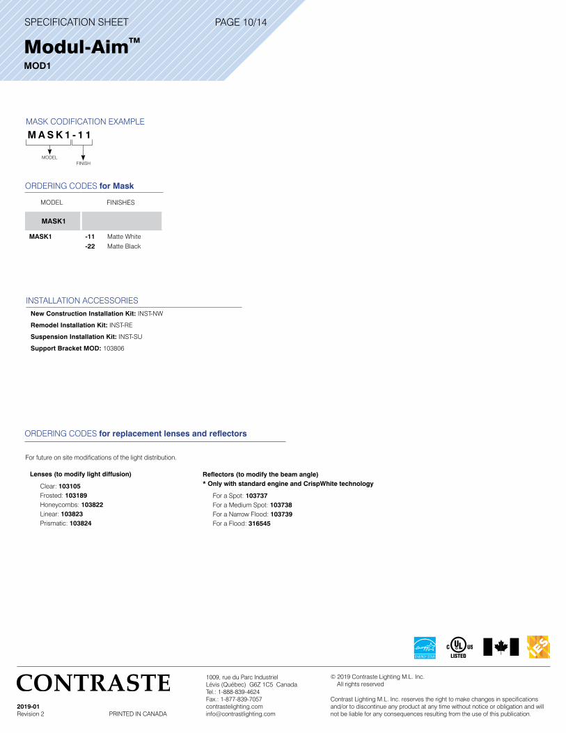
INSTALLATION ACCESSORIESNew Construction Installation Kit: INST-NW
Remodel Installation Kit: INST-RE
Suspension Installation Kit: INST-SU
Support Bracket MOD: 103806
For future on site modifications of the light distribution.
Lenses (to modify light diffusion) Clear: 103105 Frosted: 103189 Honeycombs: 103822 Linear: 103823 Prismatic: 103824
Reflectors (to modify the beam angle) * Only with standard engine and CrispWhite technology
For a Spot: 103737 For a Medium Spot: 103738 For a Narrow Flood: 103739 For a Flood: 316545
ORDERING CODES for replacement lenses and reflectors
MASK CODIFICATION EXAMPLE
M A S K 1 - 1 1
MODELFINISH
ORDERING CODES for Mask
MODEL FINISHES
MASK1
MASK1 -11
-22
Matte White
Matte Black

SPECIFICATION SHEET
1009, rue du Parc IndustrielLévis (Québec) G6Z 1C5 CanadaTel.: 1-888-839-4624Fax.: 1-877-839-7057 [email protected]
2019-01Revision 2 PRINTED IN CANADA
© 2019 Contraste Lighting M.L. Inc. All rights reserved
Contrast Lighting M.L. Inc. reserves the right to make changes in specifications and/or to discontinue any product at any time without notice or obligation and will not be liable for any consequences resulting from the use of this publication.
PHOTOMETRIC DATA
Modul-AimTM MOD1
PAGE 11/14
LUMINAIRE COEFFICIENT OF UTILIZATION - %RCC % 80 50 30RWC % 50 30 50 30 50 30RCR 0 119 119 111 111 106 106
2 108 105 103 101 100 98 4 99 95 96 93 94 92 6 92 88 90 87 89 86 8 87 82 85 82 84 8110 82 78 81 77 80 77
Zonal Cavity Method Effective Floor Cavity Reflectance 20%
3,000K, 90 + of CRI, Spot, Performance 1
CANDLEPOWER DISTRIBUTIONCandelas
ZONAL LUMEN SUMMARYZONE LUMENS %LUMINAIRE0-30 1,288.4 90.4%0-40 1,414.5 99.2%0-60 1,425.5 100%60-90 0 0%
0-90 1,425.5 100%
MULTIPLE UNIT DATA - (RCR 2)SPACING
ON CENTERINITIAL
FOOTCANDLESWATTS/SQ. FT.
5' 72 0.906' 40 0.517' 28 0.358' 28 0.359' 18 0.23
38' x 38' x 10' Room. Workplan located 2-1/2' (30").Reflection factor of 80%/50%/30%.
DEGREES/VERTICAL CANDELAS
0 12,0525 9,111
10 3,08215 1,16820 70425 61330 526
CANDELAS DISTRIBUTIONDEGREES/VERTICAL CANDELAS
40 2050 360 070 080 090 0
Distance FC DIA06’ 334.8 1.5’
08’ 188.3 2.0’
10’ 120.5 2.5’
12’ 83.7 3.0’
14’ 61.5 3.5’
16’ 47.1 4.0’
LIGHT CONE
Beam: 14.2˚ Beam Edge defined as 50% of Maximum Nadir Candlepower.15°
30°
45°
60°
75°
90°
2,167
6,500
10,833
0°
LUMINAIRE COEFFICIENT OF UTILIZATION - %RCC % 80 50 30RWC % 50 30 50 30 50 30RCR 0 119 119 111 111 106 106
2 108 105 103 101 100 98 4 99 95 96 93 94 92 6 92 88 90 87 89 86 8 87 82 85 82 84 8110 82 78 81 77 80 77
Zonal Cavity Method Effective Floor Cavity Reflectance 20%
3,000K, 90 + of CRI, Spot, Performance 2
CANDLEPOWER DISTRIBUTIONCandelas
ZONAL LUMEN SUMMARYZONE LUMENS %LUMINAIRE0-30 2,133.1 90.4%0-40 2,341.9 99.2%0-60 2,360.1 100%60-90 0 0%
0-90 2,360.1 100%
MULTIPLE UNIT DATA - (RCR 2)SPACING
ON CENTERINITIAL
FOOTCANDLESWATTS/SQ. FT.
5' 119 1.726' 67 0.967' 46 0.678' 46 0.679' 30 0.43
38' x 38' x 10' Room. Workplan located 2-1/2' (30").Reflection factor of 80%/50%/30%.
DEGREES/VERTICAL CANDELAS
0 19,9545 15,084
10 5,10315 1,93420 1,16525 1,01630 871
CANDELAS DISTRIBUTIONDEGREES/VERTICAL CANDELAS
40 3350 560 070 080 090 0
Distance FC DIA06’ 554.3 1.5’
08’ 311.8 2.0’
10’ 199.5 2.5’
12’ 138.6 3.0’
14’ 101.8 3.5’
16’ 77.9 4.0’
LIGHT CONE
Beam: 14.2˚ Beam Edge defined as 50% of Maximum Nadir Candlepower.15°
30°
45°
60°
75°
90°
3,333
10,000
16,667
0°
Modul-AimPerformance 1 LED 3,000K Spot
CBCP / Lumens 12,052 / 1,425.5
Watts 120V 277V20.42W 21.92W
Operating AMPS 0.17A 0.07ALumen Maintenance L70 @ 50,000 Hrs CRI 90+Lumens/Watt 69.8Spacing Criteria 0.25
Modul-AimPerformance 2 LED 3,000K Spot
CBCP / Lumens 19,954 / 2,360.1
Watts 120V 277V38.7W 39.2W
Operating AMPS 0.32A 0.14ALumen Maintenance L70 @ 50,000 Hrs CRI 90+Lumens/Watt 60.9Spacing Criteria 0.25
SPECIFICATION SHEET
1009, rue du Parc IndustrielLévis (Québec) G6Z 1C5 CanadaTel.: 1-888-839-4624Fax.: 1-877-839-7057 [email protected]
2019-01Revision 2 PRINTED IN CANADA
© 2019 Contraste Lighting M.L. Inc. All rights reserved
Contrast Lighting M.L. Inc. reserves the right to make changes in specifications and/or to discontinue any product at any time without notice or obligation and will not be liable for any consequences resulting from the use of this publication.
PAGE 12/14
PHOTOMETRIC DATA
Modul-AimTM MOD1
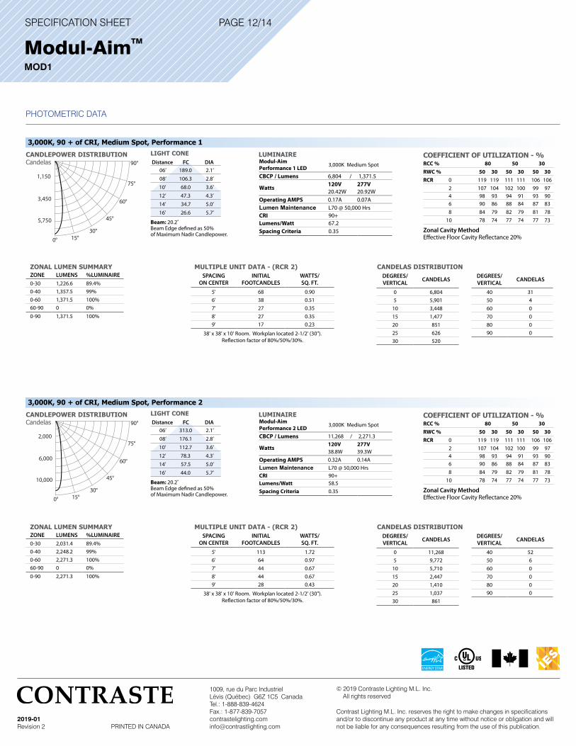
LUMINAIRE COEFFICIENT OF UTILIZATION - %RCC % 80 50 30RWC % 50 30 50 30 50 30RCR 0 119 119 111 111 106 106
2 107 104 102 100 99 97 4 98 93 94 91 93 90 6 90 86 88 84 87 83 8 84 79 82 79 81 7810 78 74 77 74 77 73
Zonal Cavity Method Effective Floor Cavity Reflectance 20%
3,000K, 90 + of CRI, Medium Spot, Performance 1
CANDLEPOWER DISTRIBUTIONCandelas
ZONAL LUMEN SUMMARYZONE LUMENS %LUMINAIRE0-30 1,226.6 89.4%0-40 1,357.5 99%0-60 1,371.5 100%60-90 0 0%
0-90 1,371.5 100%
MULTIPLE UNIT DATA - (RCR 2)SPACING
ON CENTERINITIAL
FOOTCANDLESWATTS/SQ. FT.
5' 68 0.906' 38 0.517' 27 0.358' 27 0.359' 17 0.23
38' x 38' x 10' Room. Workplan located 2-1/2' (30").Reflection factor of 80%/50%/30%.
DEGREES/VERTICAL CANDELAS
0 6,8045 5,901
10 3,44815 1,47720 85125 62630 520
CANDELAS DISTRIBUTIONDEGREES/VERTICAL CANDELAS
40 3150 460 070 080 090 0
Modul-AimPerformance 1 LED 3,000K Medium Spot
CBCP / Lumens 6,804 / 1,371.5
Watts 120V 277V20.42W 20.92W
Operating AMPS 0.17A 0.07ALumen Maintenance L70 @ 50,000 Hrs CRI 90+Lumens/Watt 67.2Spacing Criteria 0.35
Distance FC DIA06’ 189.0 2.1’
08’ 106.3 2.8’
10’ 68.0 3.6’
12’ 47.3 4.3’
14’ 34.7 5.0’
16’ 26.6 5.7’
LIGHT CONE
Beam: 20.2˚ Beam Edge defined as 50% of Maximum Nadir Candlepower.
15°30°
45°
60°
75°
90°
1,150
3,450
5,750
0°
LUMINAIRE COEFFICIENT OF UTILIZATION - %RCC % 80 50 30RWC % 50 30 50 30 50 30RCR 0 119 119 111 111 106 106
2 107 104 102 100 99 97 4 98 93 94 91 93 90 6 90 86 88 84 87 83 8 84 79 82 79 81 7810 78 74 77 74 77 73
Zonal Cavity Method Effective Floor Cavity Reflectance 20%
3,000K, 90 + of CRI, Medium Spot, Performance 2
CANDLEPOWER DISTRIBUTIONCandelas
ZONAL LUMEN SUMMARYZONE LUMENS %LUMINAIRE0-30 2,031.4 89.4%0-40 2,248.2 99%0-60 2,271.3 100%60-90 0 0%
0-90 2,271.3 100%
MULTIPLE UNIT DATA - (RCR 2)SPACING
ON CENTERINITIAL
FOOTCANDLESWATTS/SQ. FT.
5' 113 1.726' 64 0.977' 44 0.678' 44 0.679' 28 0.43
38' x 38' x 10' Room. Workplan located 2-1/2' (30").Reflection factor of 80%/50%/30%.
DEGREES/VERTICAL CANDELAS
0 11,2685 9,772
10 5,71015 2,44720 1,41025 1,03730 861
CANDELAS DISTRIBUTIONDEGREES/VERTICAL CANDELAS
40 5250 660 070 080 090 0
Modul-AimPerformance 2 LED 3,000K Medium Spot
CBCP / Lumens 11,268 / 2,271.3
Watts120V 277V38.8W 39.3W
Operating AMPS 0.32A 0.14ALumen Maintenance L70 @ 50,000 Hrs CRI 90+Lumens/Watt 58.5Spacing Criteria 0.35
Distance FC DIA06’ 313.0 2.1’
08’ 176.1 2.8’
10’ 112.7 3.6’
12’ 78.3 4.3’
14’ 57.5 5.0’
16’ 44.0 5.7’
LIGHT CONE
Beam: 20.2˚ Beam Edge defined as 50% of Maximum Nadir Candlepower.15°
30°
45°
60°
75°
90°
2,000
6,000
10,000
0°
SPECIFICATION SHEET
1009, rue du Parc IndustrielLévis (Québec) G6Z 1C5 CanadaTel.: 1-888-839-4624Fax.: 1-877-839-7057 [email protected]
2019-01Revision 2 PRINTED IN CANADA
© 2019 Contraste Lighting M.L. Inc. All rights reserved
Contrast Lighting M.L. Inc. reserves the right to make changes in specifications and/or to discontinue any product at any time without notice or obligation and will not be liable for any consequences resulting from the use of this publication.
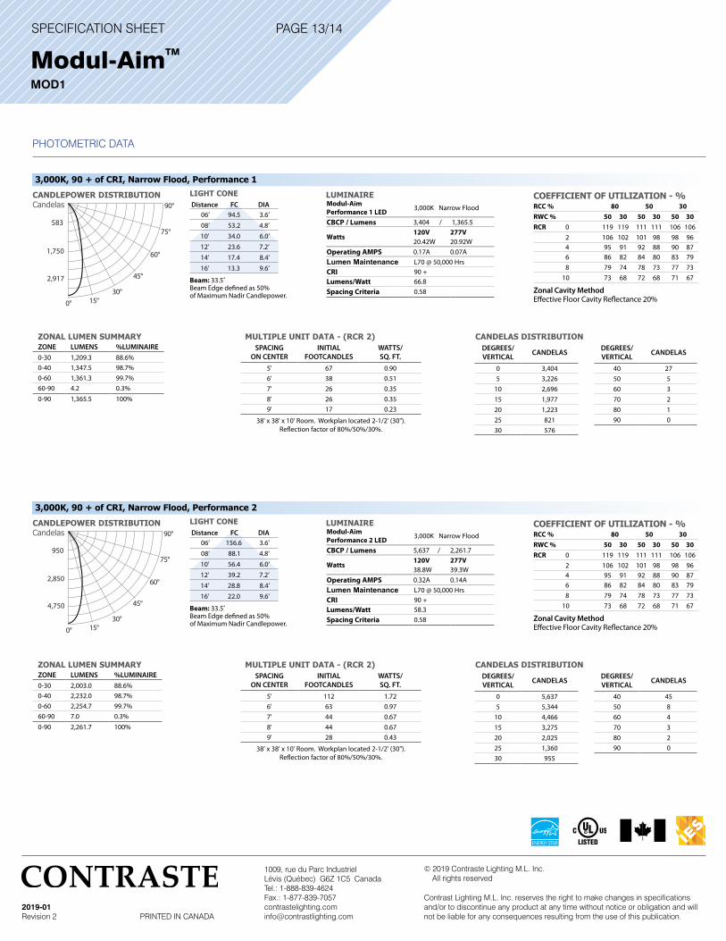
PAGE 13/14
PHOTOMETRIC DATA
Modul-AimTM MOD1
LUMINAIRE COEFFICIENT OF UTILIZATION - %RCC % 80 50 30RWC % 50 30 50 30 50 30RCR 0 119 119 111 111 106 106
2 106 102 101 98 98 96 4 95 91 92 88 90 87 6 86 82 84 80 83 79 8 79 74 78 73 77 7310 73 68 72 68 71 67
Zonal Cavity Method Effective Floor Cavity Reflectance 20%
3,000K, 90 + of CRI, Narrow Flood, Performance 1
CANDLEPOWER DISTRIBUTIONCandelas
ZONAL LUMEN SUMMARYZONE LUMENS %LUMINAIRE0-30 1,209.3 88.6%0-40 1,347.5 98.7%0-60 1,361.3 99.7%60-90 4.2 0.3%
0-90 1,365.5 100%
MULTIPLE UNIT DATA - (RCR 2)SPACING
ON CENTERINITIAL
FOOTCANDLESWATTS/SQ. FT.
5' 67 0.906' 38 0.517' 26 0.358' 26 0.359' 17 0.23
38' x 38' x 10' Room. Workplan located 2-1/2' (30").Reflection factor of 80%/50%/30%.
DEGREES/VERTICAL CANDELAS
0 3,4045 3,226
10 2,69615 1,97720 1,22325 82130 576
CANDELAS DISTRIBUTIONDEGREES/VERTICAL CANDELAS
40 2750 560 370 280 190 0
Modul-AimPerformance 1 LED 3,000K Narrow Flood
CBCP / Lumens 3,404 / 1,365.5
Watts120V 277V20.42W 20.92W
Operating AMPS 0.17A 0.07ALumen Maintenance L70 @ 50,000 Hrs CRI 90 +Lumens/Watt 66.8Spacing Criteria 0.58
Distance FC DIA06’ 94.5 3.6’
08’ 53.2 4.8’
10’ 34.0 6.0’
12’ 23.6 7.2’
14’ 17.4 8.4’
16’ 13.3 9.6’
LIGHT CONE
Beam: 33.5˚ Beam Edge defined as 50% of Maximum Nadir Candlepower.
15°30°
45°
60°
75°
90°
583
1,750
2,917
0°
LUMINAIRE COEFFICIENT OF UTILIZATION - %RCC % 80 50 30RWC % 50 30 50 30 50 30RCR 0 119 119 111 111 106 106
2 106 102 101 98 98 96 4 95 91 92 88 90 87 6 86 82 84 80 83 79 8 79 74 78 73 77 7310 73 68 72 68 71 67
Zonal Cavity Method Effective Floor Cavity Reflectance 20%
3,000K, 90 + of CRI, Narrow Flood, Performance 2
CANDLEPOWER DISTRIBUTIONCandelas
ZONAL LUMEN SUMMARYZONE LUMENS %LUMINAIRE0-30 2,003.0 88.6%0-40 2,232.0 98.7%0-60 2,254.7 99.7%60-90 7.0 0.3%
0-90 2,261.7 100%
MULTIPLE UNIT DATA - (RCR 2)SPACING
ON CENTERINITIAL
FOOTCANDLESWATTS/SQ. FT.
5' 112 1.726' 63 0.977' 44 0.678' 44 0.679' 28 0.43
38' x 38' x 10' Room. Workplan located 2-1/2' (30").Reflection factor of 80%/50%/30%.
DEGREES/VERTICAL CANDELAS
0 5,6375 5,344
10 4,46615 3,27520 2,02525 1,36030 955
CANDELAS DISTRIBUTIONDEGREES/VERTICAL CANDELAS
40 4550 860 470 380 290 0
Modul-AimPerformance 2 LED 3,000K Narrow Flood
CBCP / Lumens 5,637 / 2,261.7
Watts120V 277V38.8W 39.3W
Operating AMPS 0.32A 0.14ALumen Maintenance L70 @ 50,000 Hrs CRI 90 +Lumens/Watt 58.3Spacing Criteria 0.58
Distance FC DIA06’ 156.6 3.6’
08’ 88.1 4.8’
10’ 56.4 6.0’
12’ 39.2 7.2’
14’ 28.8 8.4’
16’ 22.0 9.6’
LIGHT CONE
Beam: 33.5˚ Beam Edge defined as 50% of Maximum Nadir Candlepower.15°
30°
45°
60°
75°
90°
950
2,850
4,750
0°
SPECIFICATION SHEET
1009, rue du Parc IndustrielLévis (Québec) G6Z 1C5 CanadaTel.: 1-888-839-4624Fax.: 1-877-839-7057 [email protected]
2019-01Revision 2 PRINTED IN CANADA
© 2019 Contraste Lighting M.L. Inc. All rights reserved
Contrast Lighting M.L. Inc. reserves the right to make changes in specifications and/or to discontinue any product at any time without notice or obligation and will not be liable for any consequences resulting from the use of this publication.
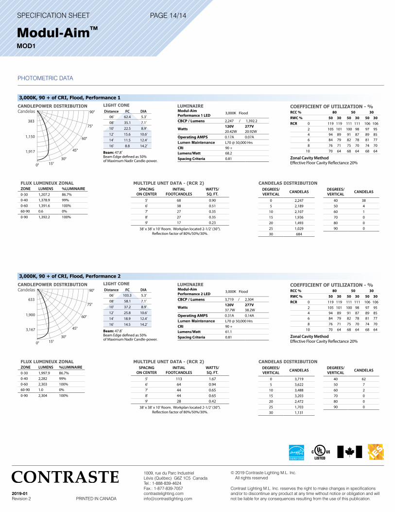
PAGE 14/14
PHOTOMETRIC DATA
Modul-AimTM MOD1
LUMINAIRE COEFFICIENT OF UTILIZATION - %RCC % 80 50 30RWC % 50 30 50 30 50 30RCR 0 119 119 111 111 106 106
2 105 101 100 98 97 95 4 94 89 91 87 89 85 6 84 79 82 78 81 77 8 76 71 75 70 74 7010 70 64 68 64 68 64
Zonal Cavity Method Effective Floor Cavity Reflectance 20%
3,000K, 90 + of CRI, Flood, Performance 1
CANDLEPOWER DISTRIBUTIONCandelas
FLUX LUMINEUX ZONALZONE LUMENS %LUMINAIRE0-30 1,207.2 86.7%0-40 1,378.9 99%0-60 1,391.6 100%60-90 0.6 0%
0-90 1,392.2 100%
MULTIPLE UNIT DATA - (RCR 2)SPACING
ON CENTERINITIAL
FOOTCANDLESWATTS/SQ. FT.
5' 68 0.906' 38 0.517' 27 0.358' 27 0.359' 17 0.23
38' x 38' x 10' Room. Workplan located 2-1/2' (30").Reflection factor of 80%/50%/30%.
DEGREES/VERTICAL CANDELAS
0 2,2475 2,189
10 2,10715 1,93620 1,49325 1,02930 684
CANDELAS DISTRIBUTIONDEGREES/VERTICAL CANDELAS
40 3850 460 170 080 090 0
Modul-AimPerformance 1 LED 3,000K Flood
CBCP / Lumens 2,247 / 1,392.2
Watts120V 277V20.42W 20.92W
Operating AMPS 0.17A 0.07ALumen Maintenance L70 @ 50,000 Hrs CRI 90 +Lumens/Watt 68.2Spacing Criteria 0.81
Distance FC DIA06’ 62.4 5.3’
08’ 35.1 7.1’
10’ 22.5 8.9’
12’ 15.6 10.6’
14’ 11.5 12.4’
16’ 8.8 14.2’
LIGHT CONE
Beam: 47.8˚ Beam Edge defined as 50% of Maximum Nadir Candle-power.
15°30°
45°
60°
75°
90°
383
1,150
1,917
0°
LUMINAIRE COEFFICIENT OF UTILIZATION - %RCC % 80 50 30RWC % 50 30 50 30 50 30RCR 0 119 119 111 111 106 106
2 105 101 100 98 97 95 4 94 89 91 87 89 85 6 84 79 82 78 81 77 8 76 71 75 70 74 7010 70 64 68 64 68 64
Zonal Cavity Method Effective Floor Cavity Reflectance 20%
3,000K, 90 + of CRI, Flood, Performance 2
CANDLEPOWER DISTRIBUTIONCandelas
FLUX LUMINEUX ZONALZONE LUMENS %LUMINAIRE0-30 1,997.9 86.7%0-40 2,282 99%0-60 2,303 100%60-90 1.0 0%
0-90 2,304 100%
MULTIPLE UNIT DATA - (RCR 2)SPACING
ON CENTERINITIAL
FOOTCANDLESWATTS/SQ. FT.
5' 113 1.676' 64 0.947' 44 0.658' 44 0.659' 28 0.42
38' x 38' x 10' Room. Workplan located 2-1/2' (30").Reflection factor of 80%/50%/30%.
DEGREES/VERTICAL CANDELAS
0 3,7195 3,622
10 3,48815 3,20320 2,47225 1,70330 1,131
CANDELAS DISTRIBUTIONDEGREES/VERTICAL CANDELAS
40 6250 760 270 080 090 0
Modul-AimPerformance 2 LED 3,000K Flood
CBCP / Lumens 3,719 / 2,304
Watts120V 277V37.7W 38.2W
Operating AMPS 0.31A 0.14ALumen Maintenance L70 @ 50,000 Hrs CRI 90 +Lumens/Watt 61.1Spacing Criteria 0.81
Distance FC DIA06’ 103.3 5.3’
08’ 58.1 7.1’
10’ 37.2 8.9’
12’ 25.8 10.6’
14’ 18.9 12.4’
16’ 14.5 14.2’
LIGHT CONE
Beam: 47.8˚ Beam Edge defined as 50% of Maximum Nadir Candle-power.15°
30°
45°
60°
75°
90°
633
1,900
3,167
0°