Embed Size (px)
Citation preview
Module 1: Part 2
Diode Circuits

Learning Objectives
After studying this module, the reader should have the ability to:
In general, apply the diode piecewise linear model in the analysis of diode circuits.
Analyze diode rectifier circuits, including the calculation of ripple voltage.
Analyze Zener diode circuits, including the effect of a Zener resistance.
Determine the output signal for a given input signal of diode clipper and clamper circuits.
Analyze circuits with multiple diodes by making initial assumptions and then verifying these initial assumptions
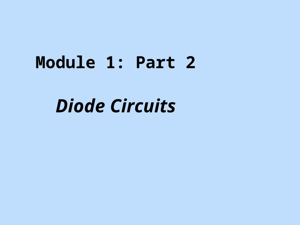
Diode in series with ac power source: (a) circuit and (b) voltage transfer characteristics

Half-wave rectifier circuit: (a) Sinusoidal input voltage, (b) output voltage, and (c) diode voltage
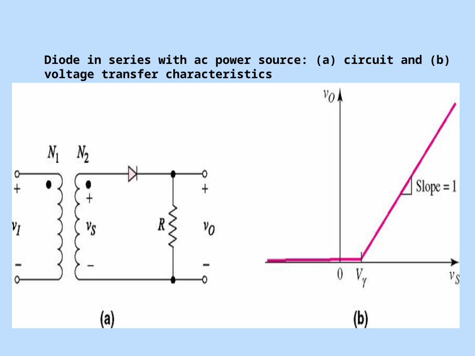
Full-wave rectifier: (a) circuit with center-tapped transformer, (b) voltage transfer characteristics, and (c) input and output waveforms
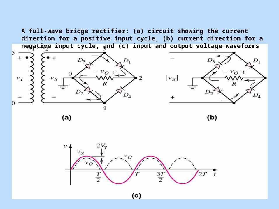
A full-wave bridge rectifier: (a) circuit showing the current direction for a positive input cycle, (b) current direction for a negative input cycle, and (c) input and output voltage waveforms
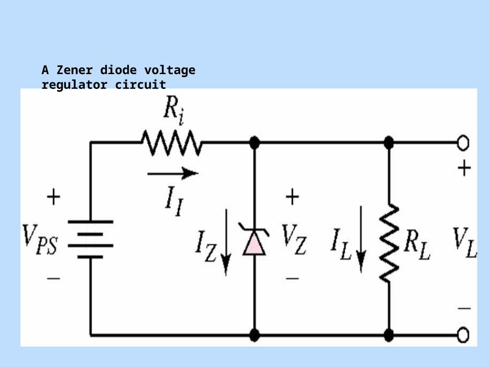
A Zener diode voltage regulator circuit
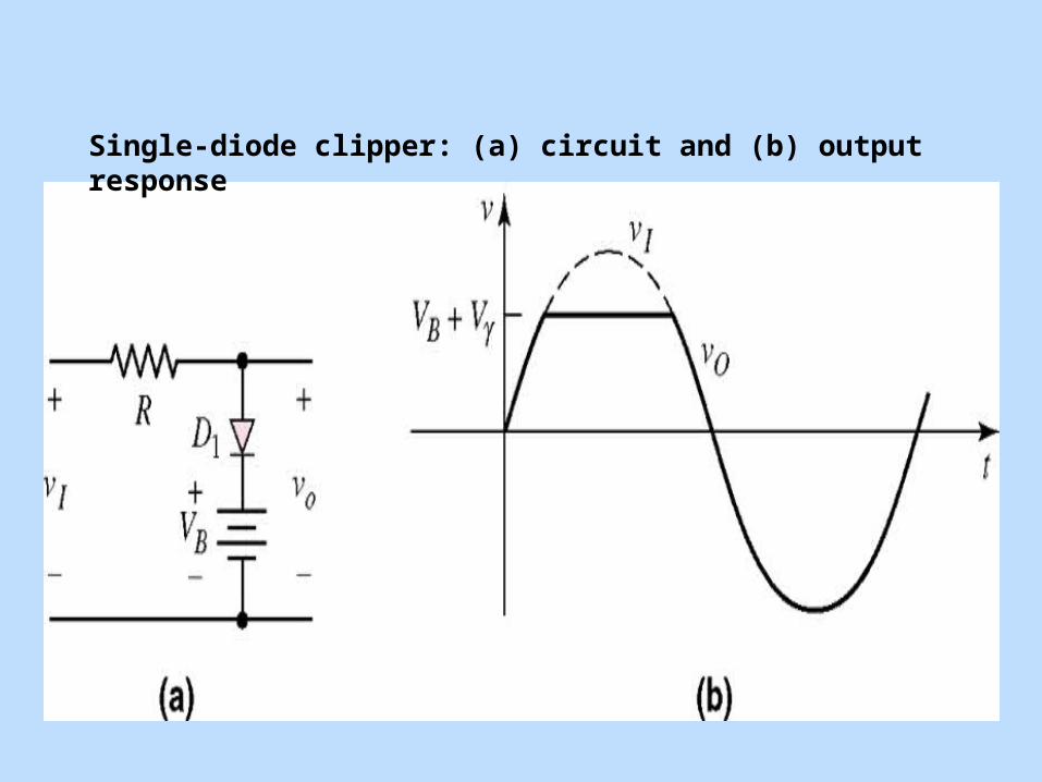
Single-diode clipper: (a) circuit and (b) output response
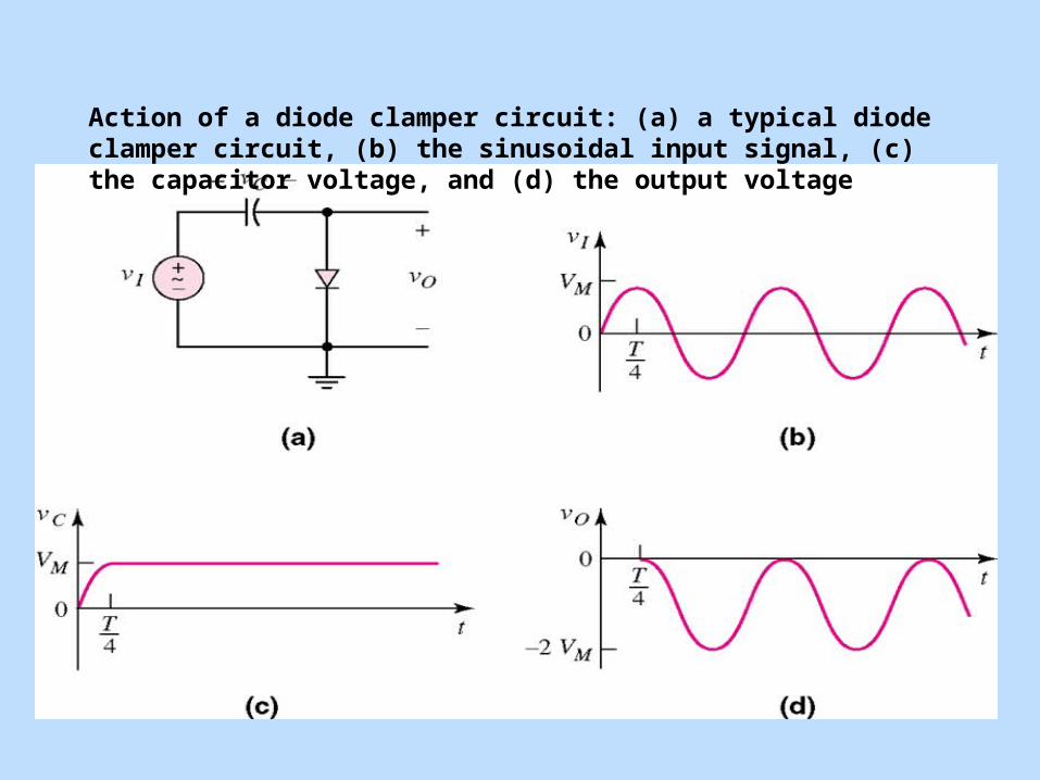
Action of a diode clamper circuit: (a) a typical diode clamper circuit, (b) the sinusoidal input signal, (c) the capacitor voltage, and (d) the output voltage

A two-diode circuit
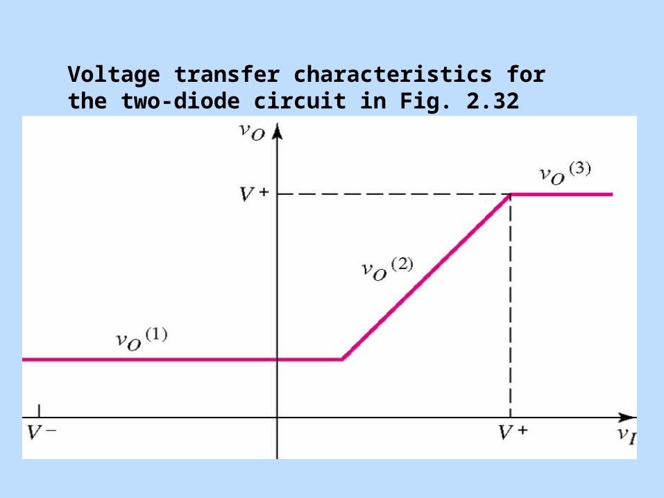
Voltage transfer characteristics for the two-diode circuit in Fig. 2.32