Embed Size (px)
Citation preview
PROPRIETARY RIGHTS STATEMENT This document contains information, which is proprietary to the MODURBAN Consortium. Neither this document nor the information contained herein shall be used, duplicated or communicated by any means to any third party,
in whole or in parts, except with prior written consent of the MODURBAN consortium.
MODURBAN FP6 Project: IP 516380
EC Contract n°: TIP4-CT-2005-516380
MODONBOARD SUBPROJECT
– DELIVERABLE REPORT –
Deliverable ID: D11 Deliverable Title: Intelligent driving prototyping Responsible partner: ALSTOM
Contributors: WP2 Partners
MODURBAN Contract: TIP4-CT-2005-516380 Deliverable Report – WP2 – D11
Doc Name: Intelligent Driving Prototyping Date: 03/03/2009 ID: DEL_MODONBOARD-D11_ALSTOM_WP2_090303 Security: PUBLIC Revision: V4 Page 2/30
Document Information
Document Name: Intelligent driving Prototyping Document ID: D11 Revision: V4 Revision Date: 2009-03-02 Author: ALSTOM Security: PUBLIC
Approvals
Name Company Date Visa
Technical Management Committee
B. VON WULLERSTORFF G. POITRASSON-RIVIERE
D. DIMMER G. LEGOFF
L. LINDQVIST U. HENNING / A. PRICE
M. NOCK JP RICHARD / D. COINEAU
Y. AMSLER C. GOUTORBE
UNIFE ALSTOM THALES
ANSALDO STS BOMBARDIER
SIEMENS KNORR BREMSE
RATP UITP ALMA
03/03/09 OK
Coordinator B. VON WULLERSTORFF UNIFE 03/03/09 OK
Subproject Coordinator G. POITRASSON-RIVIERE ALSTOM 03/03/09 OK
Quality Manager
B. VON WULLERSTORFF C. GOUTORBE
UNIFE ALMA
03/03/09 OK
Documents history
Revision Date Modification Author
V1_A 061222 Creation ALSTOM V2 08-06-03 Upgrade ALSTOM
V2-B 08-11-24 Review ALSTOM V3 09-01-26 Review ALSTOM V4 09-03-02 Review ALSTOM
MODURBAN Contract: TIP4-CT-2005-516380 Deliverable Report – WP2 – D11
Doc Name: Intelligent Driving Prototyping Date: 03/03/2009 ID: DEL_MODONBOARD-D11_ALSTOM_WP2_090303 Security: PUBLIC Revision: V4 Page 3/30
The scope of the document applies to:
Metro and Light Rail With specific
adaptation(s)/recommendation(s) (1)
Metro systems
only With no
differenciation For metro For Light Rail
Light Rail only
X (1) – Put a [D] if these adaptations/recommendations are present in the document and a [L] if they will have to be detailed later.
MODURBAN Contract: TIP4-CT-2005-516380 Deliverable Report – WP2 – D11
Doc Name: Intelligent Driving Prototyping Date: 03/03/2009 ID: DEL_MODONBOARD-D11_ALSTOM_WP2_090303 Security: PUBLIC Revision: V4 Page 4/30
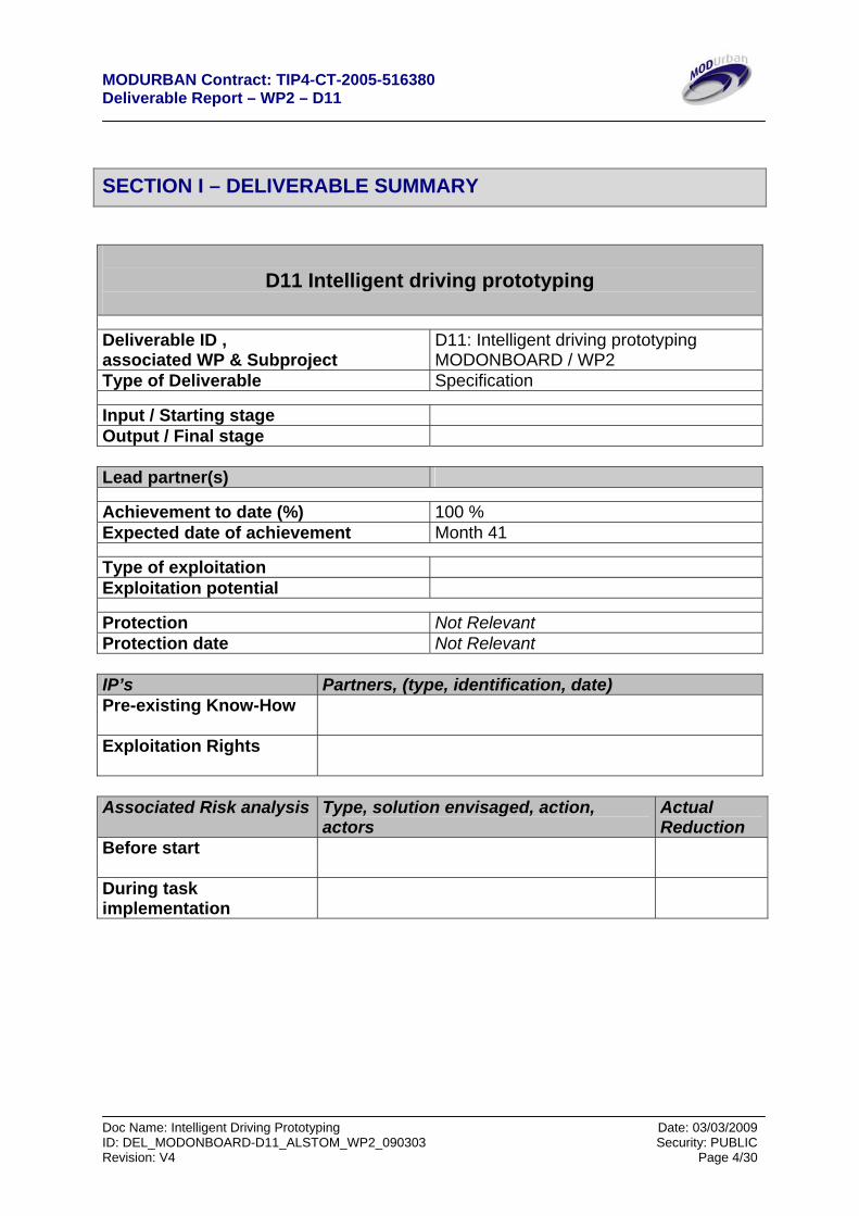
SECTION I – DELIVERABLE SUMMARY
D11 Intelligent driving prototyping
Deliverable ID , associated WP & Subproject
D11: Intelligent driving prototyping MODONBOARD / WP2
Type of Deliverable Specification
Input / Starting stage Output / Final stage Lead partner(s)
Achievement to date (%) 100 % Expected date of achievement Month 41
Type of exploitation Exploitation potential
Protection Not Relevant Protection date Not Relevant IP’s Partners, (type, identification, date) Pre-existing Know-How
Exploitation Rights
Associated Risk analysis Type, solution envisaged, action,
actors Actual Reduction
Before start
During task implementation
MODURBAN Contract: TIP4-CT-2005-516380 Deliverable Report – WP2 – D11
Doc Name: Intelligent Driving Prototyping Date: 03/03/2009 ID: DEL_MODONBOARD-D11_ALSTOM_WP2_090303 Security: PUBLIC Revision: V4 Page 5/30
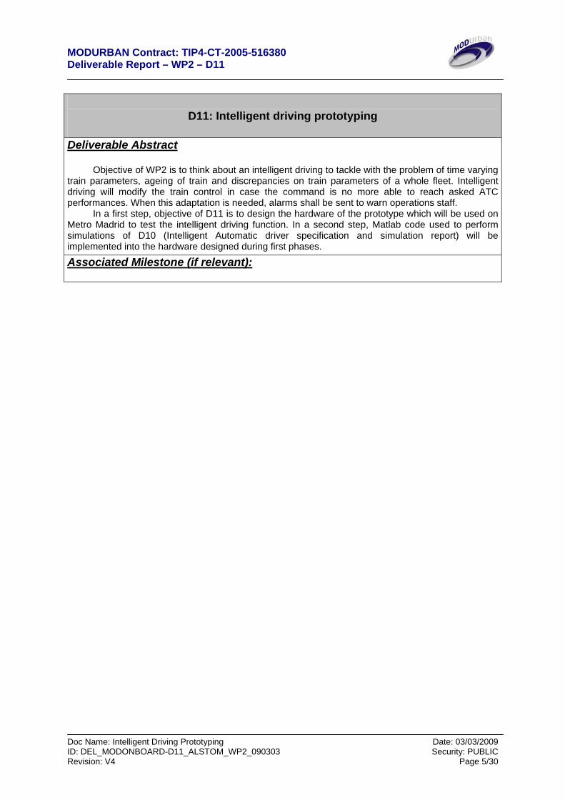
D11: Intelligent driving prototyping Deliverable Abstract
Objective of WP2 is to think about an intelligent driving to tackle with the problem of time varying train parameters, ageing of train and discrepancies on train parameters of a whole fleet. Intelligent driving will modify the train control in case the command is no more able to reach asked ATC performances. When this adaptation is needed, alarms shall be sent to warn operations staff.
In a first step, objective of D11 is to design the hardware of the prototype which will be used on Metro Madrid to test the intelligent driving function. In a second step, Matlab code used to perform simulations of D10 (Intelligent Automatic driver specification and simulation report) will be implemented into the hardware designed during first phases.
Associated Milestone (if relevant):
MODURBAN Contract: TIP4-CT-2005-516380 Deliverable Report – WP2 – D11
Doc Name: Intelligent Driving Prototyping Date: 03/03/2009 ID: DEL_MODONBOARD-D11_ALSTOM_WP2_090303 Security: PUBLIC Revision: V4 Page 6/30
TABLE OF CONTENT
1. INTRODUCTION................................................................................................. 9
1.1. Document Organisation: ........................................................................................................................ 9
1.2. Objectives: ............................................................................................................................................... 9
1.3. Conventions:............................................................................................................................................ 9
1.4. Glossary ................................................................................................................................................. 10
2. PROTOTYPE INTRODUCTION........................................................................ 11
2.1. General description .............................................................................................................................. 11
2.2. Personal Computer description ........................................................................................................... 12
2.3. Interface with odometry system .......................................................................................................... 12
2.4. Interface with TCMS............................................................................................................................ 12
2.5. Interface with Vital I/O ........................................................................................................................ 12
2.6. Interface with non Vital I/O................................................................................................................. 12
3. PROTOTYPE DESCRIPTION........................................................................... 13
3.1. Rapid Prototyping System presentation ............................................................................................. 13
3.2. Software tools ........................................................................................................................................ 13
3.3. Software description............................................................................................................................. 14
3.4. I/O definition ......................................................................................................................................... 16 3.4.1. Input Signals ...................................................................................................................................... 16 3.4.2. Output signals .................................................................................................................................... 16
3.5. RPS interface synoptic.......................................................................................................................... 18
3.6. Electrical connections ........................................................................................................................... 18 3.6.1. High voltage signals........................................................................................................................... 18 3.6.2. Low voltage signals ........................................................................................................................... 19
3.7. Summary ............................................................................................................................................... 19 3.7.1. Electrical needs .................................................................................................................................. 19 3.7.2. Connectors: ........................................................................................................................................ 20
4. MATLAB CODE IMPLEMENTATION............................................................... 20
4.1. Introduction .......................................................................................................................................... 20
4.2. Algorithm .............................................................................................................................................. 22
MODURBAN Contract: TIP4-CT-2005-516380 Deliverable Report – WP2 – D11
Doc Name: Intelligent Driving Prototyping Date: 03/03/2009 ID: DEL_MODONBOARD-D11_ALSTOM_WP2_090303 Security: PUBLIC Revision: V4 Page 7/30
4.3. Description of the different blocks: ..................................................................................................... 23 4.3.1. Inputs block........................................................................................................................................ 23 4.3.2. Tests block ......................................................................................................................................... 23 4.3.3. Generality and description of Motoring and Braking Blocks, PID anti windup description and implementation in Simulink ............................................................................................................................. 23 4.3.4. Intelligent driving block..................................................................................................................... 24 4.3.5. Outputs block ..................................................................................................................................... 24
4.4. Human Machine Interface ................................................................................................................... 26
5. TESTS............................................................................................................... 26
5.1. Functional tests ..................................................................................................................................... 26 5.1.1. Software tests ..................................................................................................................................... 26 5.1.2. Hardware tests.................................................................................................................................... 27
5.2. On track preliminary test procedure .................................................................................................. 27 5.2.1. Static phase ........................................................................................................................................ 27 5.2.2. On track tests...................................................................................................................................... 28 5.2.3. On track equipment positioning ......................................................................................................... 29 5.2.4. Demonstration preliminary scenario .................................................................................................. 30
MODURBAN Contract: TIP4-CT-2005-516380 Deliverable Report – WP2 – D11
Doc Name: Intelligent Driving Prototyping Date: 03/03/2009 ID: DEL_MODONBOARD-D11_ALSTOM_WP2_090303 Security: PUBLIC Revision: V4 Page 8/30
TABLE OF FIGURES
Figure 1. Prototype general Architecture Erreur ! Signet non défini.1
Figure 2. On board RPS synoptic Erreur ! Signet non défini.3
Figure 3. RPS general architecture Erreur ! Signet non défini.4
Figure 4. Software synopsis Erreur ! Signet non défini.5
Figure 5. Electrical connections to the rolling stocks, waves on alimentation lines represent breakers Erreur ! Signet non défini.8
Figure 6. Diagram of the different function of the model Erreur ! Signet non défini.1
Figure 7. Run sequence Erreur ! Signet non défini.8
Figure 8. Example of a run 29
Figure 9. On tracks placement of Eurobalise, safety marks departure positon and stopping position 29
MODURBAN Contract: TIP4-CT-2005-516380 Deliverable Report – WP2 – D11
Doc Name: Intelligent Driving Prototyping Date: 03/03/2009 ID: DEL_MODONBOARD-D11_ALSTOM_WP2_090303 Security: PUBLIC Revision: V4 Page 9/30
SECTION 2 – DELIVERABLE DETAILED DESCRIPTION
1. INTRODUCTION Objectives of this document are first to define the design of the hardware prototype needed to perform test on intelligent driving function. In a second part, it will include report on the implementation onto hardware of the matlab code used to perform simulation of the intelligent driving as defined in D10 document.
1.1. Document Organisation: This document is made of 5 clauses: Introduction: This section addresses the objectives of the document. Prototype introduction: This section gives a simplified hardware architecture of the prototype. It then describes rolling stock data interface used to control the train. Prototype specification: This section specifies each hardware modules and their configurations. Matlab code implementation: This section describes how matlab code used for intelligent driving simulation is implemented into the hardware previously designed. Tests: this section describes the different test to be made to validate the final demonstration and propose a preliminary scenario for it
1.2. Objectives: This document forms is part of the Work Package 2 “Onboard Intelligent Driving” which objectives are, according to the [DOW] to define and develop an intelligent automatic driving for the ATO in order to tackle with the problem of time varying train parameters, ageing of trains and discrepancies between trains in a fleet. D11 fully describes the prototype which will be used on Metro-Madrid to test the intelligent driving function.
1.3. Conventions: All physical quantity data referred in this document are described using the international system of units, in accordance with standard for Use of the International System of Units (The Modern Metric System, IEEE/ASTM SI 10-2002). All physical quantity data referred in this document are symbolised using the American National Standard Mathematical Signs and Symbols for Use in Physical Sciences and Technology (IEEE 260.3).
MODURBAN Contract: TIP4-CT-2005-516380 Deliverable Report – WP2 – D11
Doc Name: Intelligent Driving Prototyping Date: 03/03/2009 ID: DEL_MODONBOARD-D11_ALSTOM_WP2_090303 Security: PUBLIC Revision: V4 Page 10/30
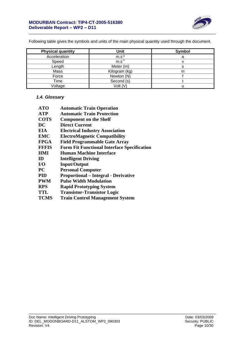
Following table gives the symbols and units of the main physical quantity used through the document.
Physical quantity Unit Symbol Acceleration m.s-² a
Speed m.s-1 v Length Meter (m) s Mass Kilogram (kg) m Force Newton (N) f Time Second (s) t
Voltage Volt (V) u
1.4. Glossary
ATO Automatic Train Operation ATP Automatic Train Protection COTS Component on the Shelf DC Direct Current EIA Electrical Industry Association EMC ElectroMagnetic Compatibility FPGA Field Programmable Gate Array FFFIS Form Fit Functional Interface Specification HMI Human Machine Interface ID Intelligent Driving I/O Input/Output PC Personal Computer PID Proportional – Integral - Derivative PWM Pulse Width Modulation RPS Rapid Prototyping System TTL Transistor-Transistor Logic TCMS Train Control Management System
MODURBAN Contract: TIP4-CT-2005-516380 Deliverable Report – WP2 – D11
Doc Name: Intelligent Driving Prototyping Date: 03/03/2009 ID: DEL_MODONBOARD-D11_ALSTOM_WP2_090303 Security: PUBLIC Revision: V4 Page 11/30
2. Prototype introduction
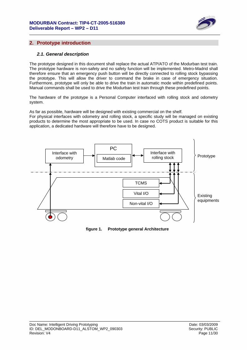
2.1. General description The prototype designed in this document shall replace the actual ATP/ATO of the Modurban test train. The prototype hardware is non-safety and no safety function will be implemented. Metro-Madrid shall therefore ensure that an emergency push button will be directly connected to rolling stock bypassing the prototype. This will allow the driver to command the brake in case of emergency situation. Furthermore, prototype will only be able to drive the train in automatic mode within predefined points. Manual commands shall be used to drive the Modurban test train through these predefined points. The hardware of the prototype is a Personal Computer interfaced with rolling stock and odometry system. As far as possible, hardware will be designed with existing commercial on the shelf. For physical interfaces with odometry and rolling stock, a specific study will be managed on existing products to determine the most appropriate to be used. In case no COTS product is suitable for this application, a dedicated hardware will therefore have to be designed.
figure 1. Prototype general Architecture
PC
Matlab codeInterface with
odometry Interface with rolling stock
TCMS
Vital I/O
Non-vital I/O
Prototype
Existing equipments
MODURBAN Contract: TIP4-CT-2005-516380 Deliverable Report – WP2 – D11
Doc Name: Intelligent Driving Prototyping Date: 03/03/2009 ID: DEL_MODONBOARD-D11_ALSTOM_WP2_090303 Security: PUBLIC Revision: V4 Page 12/30
2.2. Personal Computer description
The personal computer shall perform the following functions:
- Drive the train: to perform this function, the matlab code already defined in D10 will be implemented with no modification of the control function. The follow up of a running type and the service brake application while the train is stopped will also be implemented. Several running types will be defined according to the test track and the real line available for testing.
- Inform the engineer: this function will provide and interface with the engineer performing
the tests as speed, covered distance, command values. The set of information shall be defined later on.
- Start/stop: this command will start/stop the automatic command when prototype receives a
command from the driver through a push button or in case of an emergency brake request.
- Application of a disturbance on the command: In order to allow testing of the robustness of
the intelligent driving, it is necessary to add a disturbance directly onto the command. This disturbance will be set by modifying a parameter in the PC.
2.3. Interface with odometry system
Metro Madrid has to provide the complete existing FFFIS interface between existing odometry system and the existing ATP/ATO. The use of this interface will then be defined in this paragraph.
2.4. Interface with TCMS Metro Madrid has to provide the complete existing FFFIS interface between existing TCMS and existing ATP/ATO. This interface will be used to command the train. The use of this interface will then be defined in this paragraph.
2.5. Interface with Vital I/O
Metro Madrid has to provide the complete existing FFFIS interface between existing Vital I/O and existing ATP/ATO. This interface is needed to cut-off commands while an emergency brake is being applied. The use of this interface will then be defined in this paragraph.
2.6. Interface with non Vital I/O Metro Madrid has to provide the complete existing FFFIS interface between existing non Vital I/O and existing ATP/ATO. This interface will be used for instance to have the Start/stop information. The use of this interface will then be defined in this paragraph.
MODURBAN Contract: TIP4-CT-2005-516380 Deliverable Report – WP2 – D11
Doc Name: Intelligent Driving Prototyping Date: 03/03/2009 ID: DEL_MODONBOARD-D11_ALSTOM_WP2_090303 Security: PUBLIC Revision: V4 Page 13/30
3. Prototype description
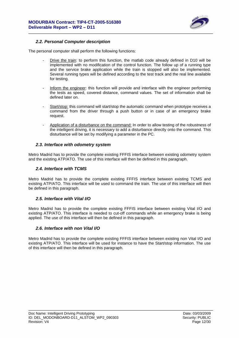
3.1. Rapid Prototyping System presentation The RPS is a compact portable system that replaces the ATO/ATP. It’s composed of a PC panel touch screen to host an HMI and the Matlab/Simulink environment, a target PC to host the real time kernel and drives the interfaces board. The RPS has to be plugged and unplugged easily. The following diagram shows a view of the system.
figure 2. On board RPS synoptic
N.B: As the RPS isn’t security safe, it requires a driver in case of failure. The driver will always have the priority on the system. An interface with the pilot is foreseen and could be numerical or not.
3.2. Software tools The model is implemented in a Matlab/Simulink platform using real-time Work-shop toolboxes and xPC target to manage I/O interfaces.
Alim(s) (220V)
Odometer
Top EuroBalise
Target PC
Cartes
I/O
PC Supervisor + HMI Touch screen
Screen 2 TRA
IN I
nter
face
Braking/Traction
Eurobalise Board
Antennae Eurobalise Pilote
Interface
ALSTOM Metro Madrid
MODURBAN Contract: TIP4-CT-2005-516380 Deliverable Report – WP2 – D11
Doc Name: Intelligent Driving Prototyping Date: 03/03/2009 ID: DEL_MODONBOARD-D11_ALSTOM_WP2_090303 Security: PUBLIC Revision: V4 Page 14/30
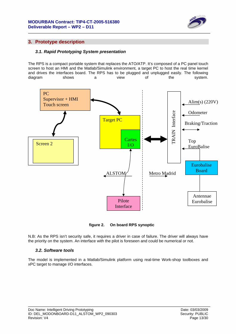
figure 3. RPS general architecture
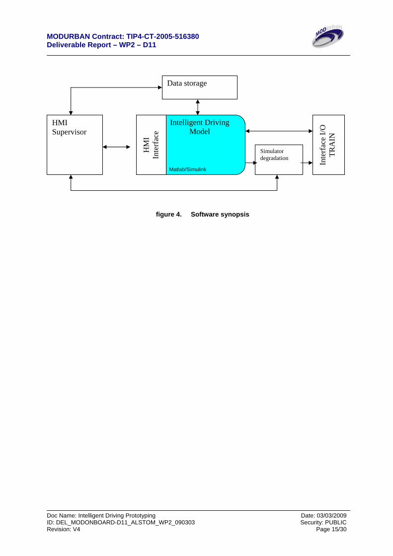
3.3. Software description
The software architecture comprises several modules:
• HMI management, • data storage, • degradation simulator, • Intelligent Driving • I/O real time management system.
PC SUPERVISOR Environnement Matlab Simulink
Real Time Workshop
xPC Target (Matlab)
TARGET PC (X86) + I/O Boards
HMI (Visual C++)
MODURBAN Contract: TIP4-CT-2005-516380 Deliverable Report – WP2 – D11
Doc Name: Intelligent Driving Prototyping Date: 03/03/2009 ID: DEL_MODONBOARD-D11_ALSTOM_WP2_090303 Security: PUBLIC Revision: V4 Page 15/30
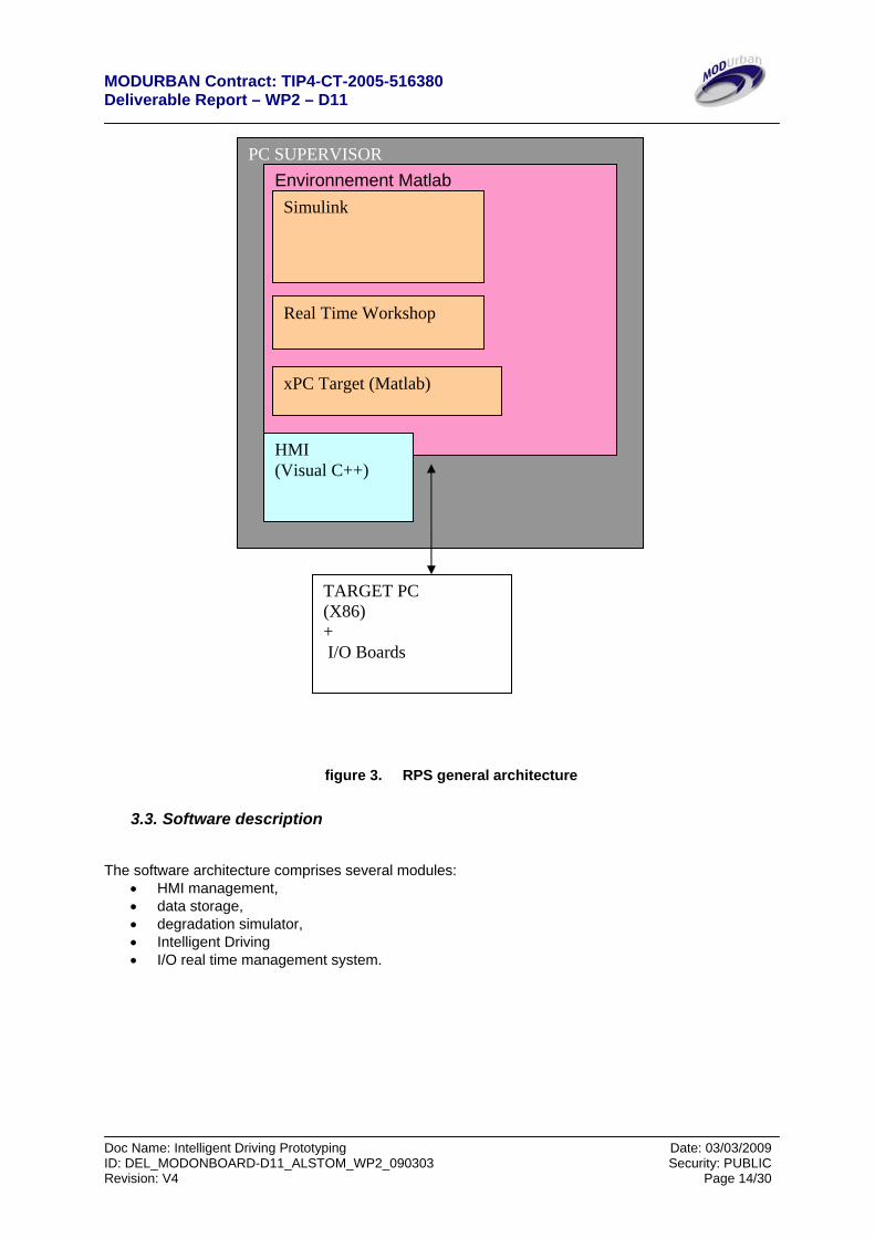
figure 4. Software synopsis
Intelligent Driving Model
Matlab/Simulink
HM
I In
terf
ace
HMI Supervisor
Inte
rfac
e I/O
TR
AIN
Simulator degradation
Data storage
MODURBAN Contract: TIP4-CT-2005-516380 Deliverable Report – WP2 – D11
Doc Name: Intelligent Driving Prototyping Date: 03/03/2009 ID: DEL_MODONBOARD-D11_ALSTOM_WP2_090303 Security: PUBLIC Revision: V4 Page 16/30
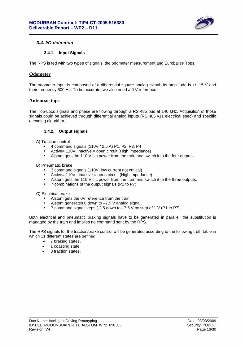
3.4. I/O definition
3.4.1. Input Signals The RPS is fed with two types of signals: the odometer measurement and Eurobalise Tops. Odometer The odometer input is composed of a differential square analog signal. Its amplitude is +/- 15 V and their frequency 600 Hz. To be accurate, we also need a 0 V reference. Antennae tops The Top-Locs signals and phase are flowing through a RS 485 bus at 140 kHz. Acquisition of those signals could be achieved through differential analog inputs (RS 485 v11 electrical spec) and specific decoding algorithm.
3.4.2. Output signals
A) Traction control 4 command signals (110V / 2,5 A) P1, P2, P3, P4 Active= 110V inactive = open circuit (High impedance) Alstom gets the 110 V c.c power from the train and switch it to the four outputs.
B) Pneumatic brake
3 command signals (110V, low current not critical) Active= 110V , inactive = open circuit (High impedance) Alstom gets the 110 V c.c power from the train and switch it to the three outputs. 7 combinations of the output signals (P1 to P7)
C) Electrical brake
Alstom gets the 0V reference from the train Alstom generates 0 down to –7,5 V analog signal 7 command signal steps (-2,5 down to –7,5 V by step of 1 V (P1 to P7)
Both electrical and pneumatic braking signals have to be generated in parallel; the substitution is managed by the train and implies no command sent by the RPS. The RPS signals for the traction/brake control will be generated according to the following truth table in which 11 different states are defined:
• 7 braking states, • 1 coasting state • 3 traction states.
MODURBAN Contract: TIP4-CT-2005-516380 Deliverable Report – WP2 – D11
Doc Name: Intelligent Driving Prototyping Date: 03/03/2009 ID: DEL_MODONBOARD-D11_ALSTOM_WP2_090303 Security: PUBLIC Revision: V4 Page 17/30
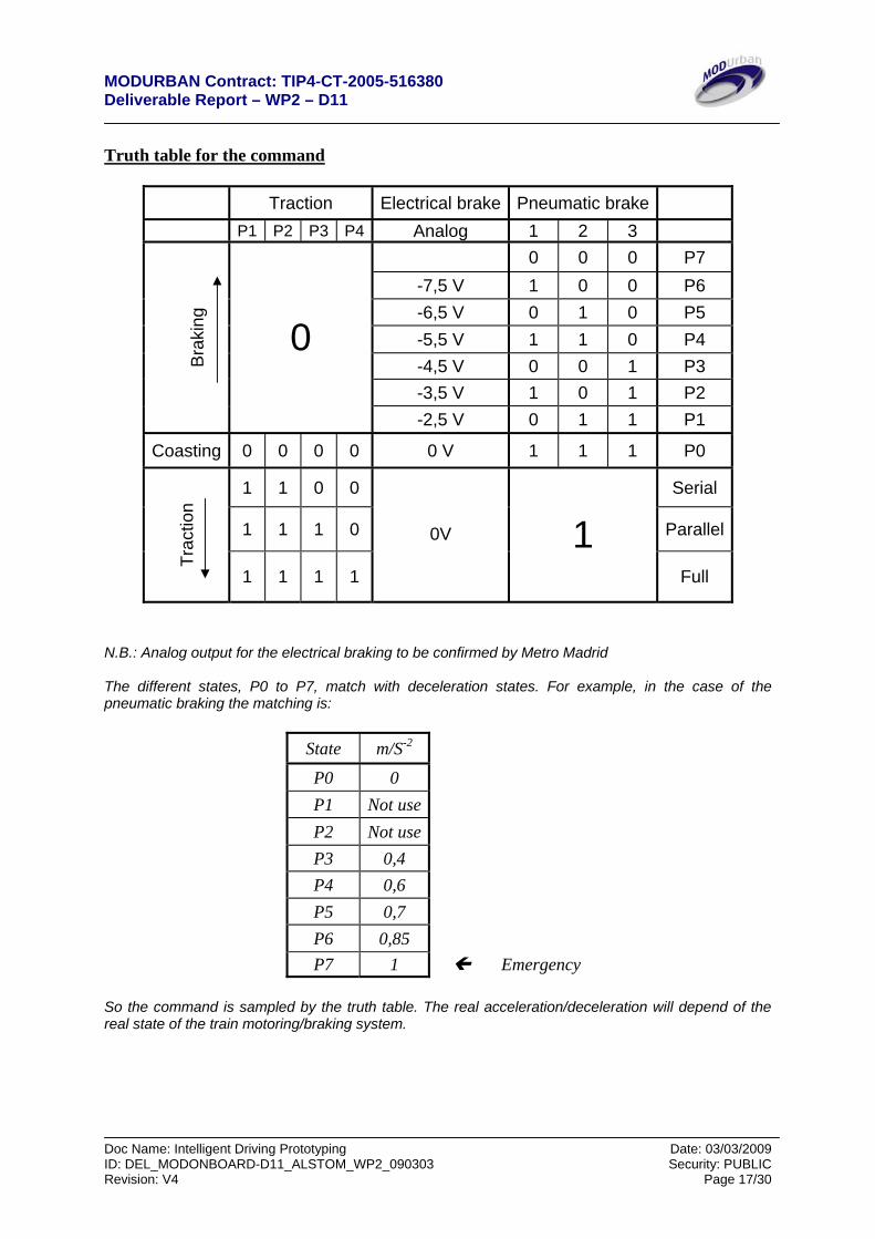
Truth table for the command
Traction Electrical brake Pneumatic brake P1 P2 P3 P4 Analog 1 2 3
0 0 0 P7 -7,5 V 1 0 0 P6 -6,5 V 0 1 0 P5 -5,5 V 1 1 0 P4 -4,5 V 0 0 1 P3 -3,5 V 1 0 1 P2
B
raki
ng
0
-2,5 V 0 1 1 P1
Coasting 0 0 0 0 0 V 1 1 1 P0
1 1 0 0 Serial
1 1 1 0 Parallel
Trac
tion
1 1 1 1
0V 1 Full
N.B.: Analog output for the electrical braking to be confirmed by Metro Madrid The different states, P0 to P7, match with deceleration states. For example, in the case of the pneumatic braking the matching is:
State m/S-2
P0 0 P1 Not useP2 Not useP3 0,4 P4 0,6 P5 0,7 P6 0,85 P7 1 Emergency
So the command is sampled by the truth table. The real acceleration/deceleration will depend of the real state of the train motoring/braking system.
MODURBAN Contract: TIP4-CT-2005-516380 Deliverable Report – WP2 – D11
Doc Name: Intelligent Driving Prototyping Date: 03/03/2009 ID: DEL_MODONBOARD-D11_ALSTOM_WP2_090303 Security: PUBLIC Revision: V4 Page 18/30
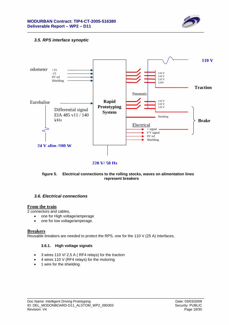
3.5. RPS interface synoptic
figure 5. Electrical connections to the rolling stocks, waves on alimentation lines represent breakers
3.6. Electrical connections From the train 2 connectors and cables,
• one for High voltage/amperage • one for low voltage/amperage.
Breakers Reusable breakers are needed to protect the RPS, one for the 110 V (25 A) interfaces.
3.6.1. High voltage signals
• 3 wires 110 V/ 2,5 A ( RF4 relays) for the traction • 4 wires 110 V (RF4 relays) for the motoring • 1 wire for the shielding.
Traction
Rapid Prototyping
System
+15 -15 0V ref Shielding
+ signal 0 V signal 0V ref Shielding
110 V 110 V 110 V Shielding
110 V 110 V 110 V 110V
Pneumatic
Electrical Brake
110 V
24 V alim /100 W
220 V/ 50 Hz
odometer
Eurobalise Differential signal EIA 485 v11 / 140 kHz
MODURBAN Contract: TIP4-CT-2005-516380 Deliverable Report – WP2 – D11
Doc Name: Intelligent Driving Prototyping Date: 03/03/2009 ID: DEL_MODONBOARD-D11_ALSTOM_WP2_090303 Security: PUBLIC Revision: V4 Page 19/30
3.6.2. Low voltage signals
• Antennae top Two wire for the RS 485 connection • Odometer; 2 signals + 0 ref
4 wires • 0 V ref • Shielding • 0 V signal • + V signal
Alimentation • Need of an alimentation in 110V for the pneumatic breaking and the traction • 24 V/ 100 W for the antennae beacon • 220 V to power the RPS hardware
To protect the different entities we recommend using breakers on the entire alimentation sources.
3.7. Summary
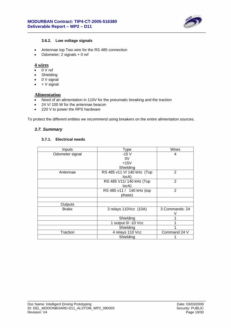
3.7.1. Electrical needs
Inputs Type Wires Odometer signal -15 V
0V +15V
Shielding
4
Antennae RS 485 v11 V/ 140 kHz (Top locA)
2
RS 485 V11/ 140 kHz (Top locA)
2
RS 485 v11 / 140 kHz (top phase)
2
Outputs Brake 3 relays 110Vcc (10A) 3 Commands: 24
V Shielding 1 1 output 0/ -10 Vcc 1 Shielding 1
Traction 4 relays 110 Vcc Command 24 V Shielding 1
MODURBAN Contract: TIP4-CT-2005-516380 Deliverable Report – WP2 – D11
Doc Name: Intelligent Driving Prototyping Date: 03/03/2009 ID: DEL_MODONBOARD-D11_ALSTOM_WP2_090303 Security: PUBLIC Revision: V4 Page 20/30
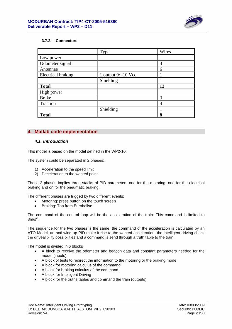
3.7.2. Connectors:
Type Wires Low power Odometer signal 4 Antennae 6 Electrical braking 1 output 0/ -10 Vcc 1 Shielding 1 Total 12 High power Brake 3 Traction 4 Shielding 1 Total 8
4. Matlab code implementation
4.1. Introduction This model is based on the model defined in the WP2-10. The system could be separated in 2 phases:
1) Acceleration to the speed limit 2) Deceleration to the wanted point
Those 2 phases implies three stacks of PID parameters one for the motoring, one for the electrical braking and on for the pneumatic braking. The different phases are trigged by two different events:
• Motoring: press button on the touch screen • Braking: Top from Eurobalise
The command of the control loop will be the acceleration of the train. This command is limited to 3m/s2. The sequence for the two phases is the same: the command of the acceleration is calculated by an ATO Model, an anti wind up PID make it rise to the wanted acceleration, the intelligent driving check the drivealibility possibilities and a command is send through a truth table to the train. The model is divided in 6 blocks
• A block to receive the odometer and beacon data and constant parameters needed for the model (inputs)
• A block of tests to redirect the information to the motoring or the braking mode • A block for motoring calculus of the command • A block for braking calculus of the command • A block for Intelligent Driving • A block for the truths tables and command the train (outputs)
MODURBAN Contract: TIP4-CT-2005-516380 Deliverable Report – WP2 – D11
Doc Name: Intelligent Driving Prototyping Date: 03/03/2009 ID: DEL_MODONBOARD-D11_ALSTOM_WP2_090303 Security: PUBLIC Revision: V4 Page 21/30
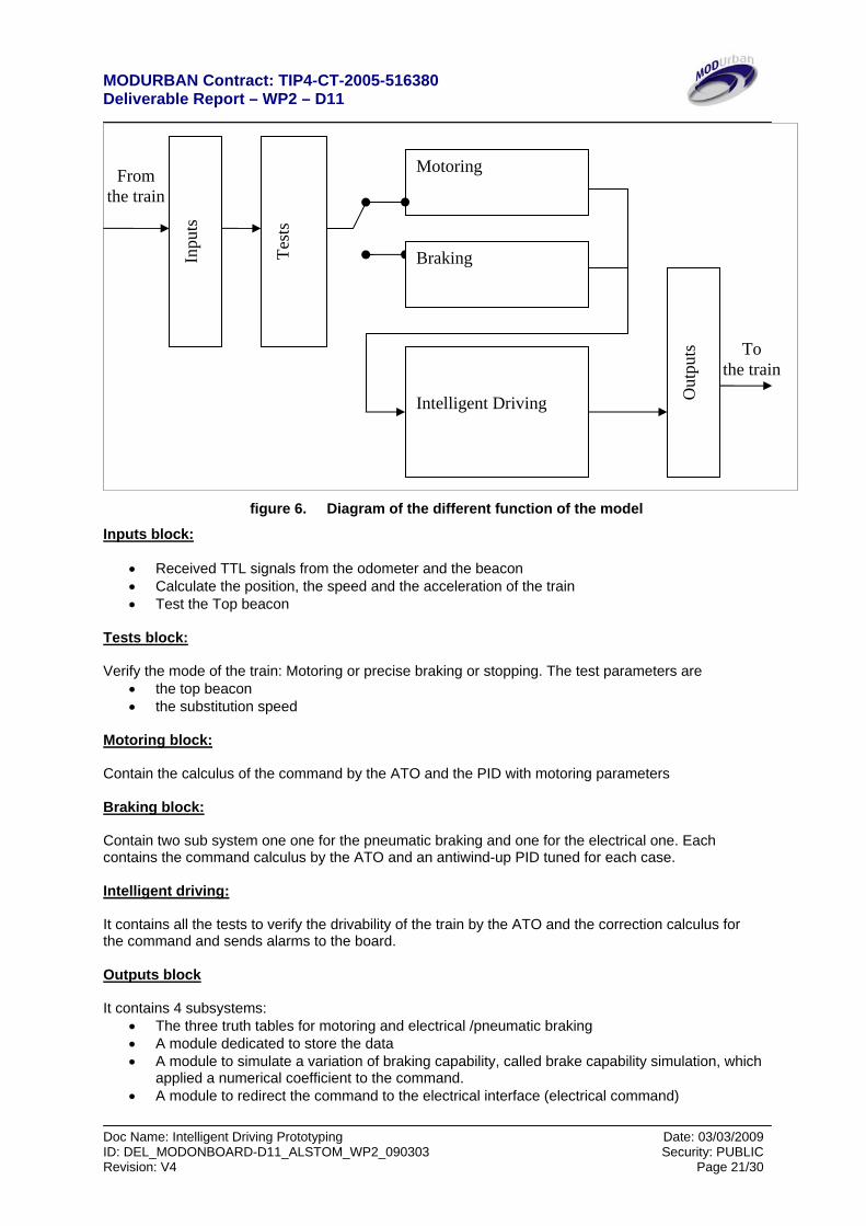
figure 6. Diagram of the different function of the model
Inputs block:
• Received TTL signals from the odometer and the beacon • Calculate the position, the speed and the acceleration of the train • Test the Top beacon
Tests block: Verify the mode of the train: Motoring or precise braking or stopping. The test parameters are
• the top beacon • the substitution speed
Motoring block: Contain the calculus of the command by the ATO and the PID with motoring parameters Braking block: Contain two sub system one one for the pneumatic braking and one for the electrical one. Each contains the command calculus by the ATO and an antiwind-up PID tuned for each case. Intelligent driving: It contains all the tests to verify the drivability of the train by the ATO and the correction calculus for the command and sends alarms to the board. Outputs block It contains 4 subsystems:
• The three truth tables for motoring and electrical /pneumatic braking • A module dedicated to store the data • A module to simulate a variation of braking capability, called brake capability simulation, which
applied a numerical coefficient to the command. • A module to redirect the command to the electrical interface (electrical command)
Inpu
ts
Intelligent Driving O
utpu
ts
Test
s
Motoring
Braking
To the train
From the train
MODURBAN Contract: TIP4-CT-2005-516380 Deliverable Report – WP2 – D11
Doc Name: Intelligent Driving Prototyping Date: 03/03/2009 ID: DEL_MODONBOARD-D11_ALSTOM_WP2_090303 Security: PUBLIC Revision: V4 Page 22/30
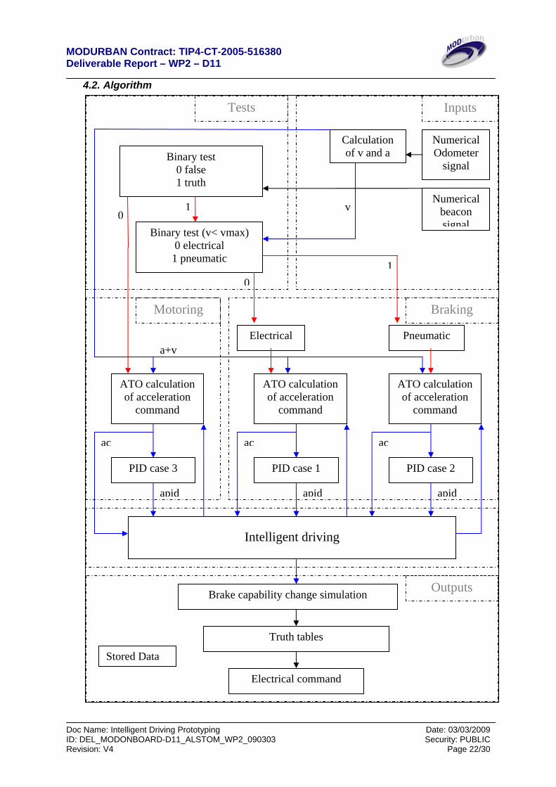
4.2. Algorithm
Numerical Odometer
signal
Calculation of v and a
Numerical beacon signal
0
a+v
Binary test (v< vmax) 0 electrical 1 pneumatic
Binary test 0 false 1 truth
Motoring
Electrical Pneumatic
ATO calculation of acceleration
command
PID case 3
Intelligent driving
ac
apid
PID case 1
ac
apid
PID case 2
ac
apid
ATO calculation of acceleration
command
ATO calculation of acceleration
command
Electrical command
1
01
v
Brake capability change simulation
Braking
Outputs
Tests Inputs
Truth tables
Stored Data
MODURBAN Contract: TIP4-CT-2005-516380 Deliverable Report – WP2 – D11
Doc Name: Intelligent Driving Prototyping Date: 03/03/2009 ID: DEL_MODONBOARD-D11_ALSTOM_WP2_090303 Security: PUBLIC Revision: V4 Page 23/30
4.3. Description of the different blocks:
4.3.1. Inputs block Odometer signal reception
• Routing of the two signals by an xPC target module • Calculation of the differential signals to obtain the value of the odometer
Beacon signal reception
• Routing of the three signals by an xPC target module • Calculation of the top beacon
Calculus:
• arithmetical addition of the theoretical value in meters of each tops • derivation of the odometer signal to obtain the train speed and acceleration • increment of a sequence counter
4.3.2. Tests block
• Test the top beacon signal, when it’s received the parameter passed from 0 to 1 • Test the velocity of the train, while the speed excided the substitution speed the test
parameter is set to 0, pass to 1 when the speed is below to set the correct parameters for the PID
4.3.3. Generality and description of Motoring and Braking Blocks, PID anti windup
description and implementation in Simulink The reason why a PID Anti windup is used and its principles are explicated in the document [WP2.D10/9]. The PID module detects the train evolution and applies the numerical values which comply with the different cases. Is implemented in each motoring and electrical/braking block. In each case its parameters are different to comply with the physical characteristics of each following cases:
• Case 1: electrical Braking • Case 2: pneumatic Braking • Case 3: motoring
PID parameters Case 1 Case 2 Case 3
K 0,9 1,9 0,9 Ti 1,9 4 1,9 Td 1,4 4 1,4
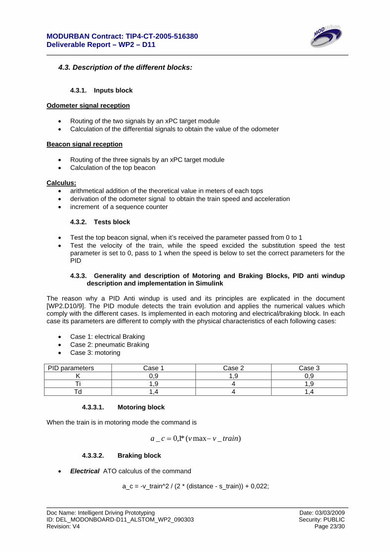
4.3.3.1. Motoring block
When the train is in motoring mode the command is
)_max(*1,0_ trainvvca −=
4.3.3.2. Braking block
• Electrical ATO calculus of the command
a_c = -v_train^2 / (2 * (distance - s_train)) + 0,022;
MODURBAN Contract: TIP4-CT-2005-516380 Deliverable Report – WP2 – D11
Doc Name: Intelligent Driving Prototyping Date: 03/03/2009 ID: DEL_MODONBOARD-D11_ALSTOM_WP2_090303 Security: PUBLIC Revision: V4 Page 24/30
• Pneumatic ATO calculus of the command If the distance - s_train < 0 or v_train < v_delta_a * 3,6/5 (3,6/5 5 km/h) Then the commande is a_c = 0,1 * (v_max - v_train); else a_c = a_c_prev;
4.3.4. Intelligent driving block
The intelligent driving module is made to correct the ATO command in case of over or under braking. To detect those cases 2 variables (tampon1 & tampon 2) are calculated from the filtered values of the command and the PID. They are compared to the ATO’s range of drivability. The I.D. correct the ATO’s if is out of range and is able to send alarms in cases of overbraking or underbraking. The correction is calculated with the measurement made in the previous runs and applied with a logarithmic law as an offset on the new command.
4.3.5. Outputs block We use the truth table define in the paragraph 3.4.2 to command the motoring and the braking modes. Acceleration command is transformed as stepped acceleration by the truth tables witch commands relays on interfaces boards.
4.3.5.1. Brake capability change simulation To simulate a degradation of the braking capability without touching the mechanic of the rolling stock, we apply a correction on the acceleration command. This parameter would be set at the beginning of a test series.
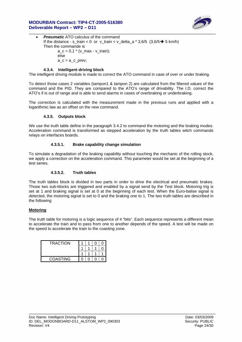
4.3.5.2. Truth tables The truth tables block is divided in two parts in order to drive the electrical and pneumatic brakes. Those two sub-blocks are triggered and enabled by a signal send by the Test block. Motoring trig is set at 1 and braking signal is set at 0 at the beginning of each test. When the Euro-balise signal is detected, the motoring signal is set to 0 and the braking one to 1. The two truth tables are described in the following Motoring The truth table for motoring is a logic sequence of 4 “bits”. Each sequence represents a different mean to accelerate the train and to pass from one to another depends of the speed. A test will be made on the speed to accelerate the train to the coasting zone.
1 1 0 01 1 1 0
TRACTION
1 1 1 1COASTING 0 0 0 0
MODURBAN Contract: TIP4-CT-2005-516380 Deliverable Report – WP2 – D11
Doc Name: Intelligent Driving Prototyping Date: 03/03/2009 ID: DEL_MODONBOARD-D11_ALSTOM_WP2_090303 Security: PUBLIC Revision: V4 Page 25/30
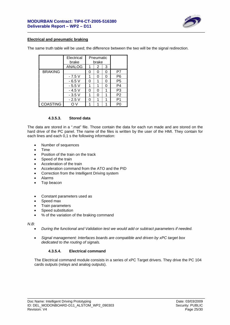
Electrical and pneumatic braking The same truth table will be used; the difference between the two will be the signal redirection.
Electrical
brake Pneumatic
brake
ANALOG 1 2 3
0 0 0 P7 - 7.5 V 1 0 0 P6 - 6.5 V 0 1 0 P5 - 5.5 V 1 1 0 P4 - 4.5 V 0 0 1 P3 - 3.5 V 1 0 1 P2
BRAKING
- 2.5 V 0 1 1 P1 COASTING O V 1 1 1 P0
4.3.5.3. Stored data
The data are stored in a “.mat” file. Those contain the data for each run made and are stored on the hard drive of the PC panel. The name of the files is written by the user of the HMI. They contain for each lines and each 0,1 s the following information:
• Number of sequences • Time • Position of the train on the track • Speed of the train • Acceleration of the train • Acceleration command from the ATO and the PID • Correction from the Intelligent Driving system • Alarms • Top beacon
• Constant parameters used as • Speed max • Train parameters • Speed substitution • % of the variation of the braking command
N.B:
• During the functional and Validation test we would add or subtract parameters if needed.
• Signal management: Interfaces boards are compatible and driven by xPC target box dedicated to the routing of signals.
4.3.5.4. Electrical command
The Electrical command module consists in a series of xPC Target drivers. They drive the PC 104 cards outputs (relays and analog outputs).
MODURBAN Contract: TIP4-CT-2005-516380 Deliverable Report – WP2 – D11
Doc Name: Intelligent Driving Prototyping Date: 03/03/2009 ID: DEL_MODONBOARD-D11_ALSTOM_WP2_090303 Security: PUBLIC Revision: V4 Page 26/30
4.4. Human Machine Interface
The HMI will be implemented in the PC panel touch-screen. It will have at least 3 pages.
• Page 1: management of the runs and visual information • Page 2: data management • Page 3: verification of the system (tests and alarms)
Page 1 The page 1 contains
• a button to launch the model and start the automatic phase • graphical interfaces showing evolution of the speed and the measured acceleration during the
run compared to the nominal run, ATO set point in a color and I.D set point • A bar showing the position of the train on the track during the run • Indicators • Monitoring of the parameters and data of the activity of the Intelligent driving • Two text boxes to enter the number of the run and choose the change simulation parameter
for the brake capability
Page 2 This page only consists in text box and it will be used only for tests sequences. This page is dedicated to manage the name of the files the register the runs parameters and data. It has two functions:
• manage the recording of the data • reload former data
It will have a graphical interface to show what the data we want to reload looks like. Page 3 This page is dedicated to on board testing 5. Tests Those test are made to verify that’s the hardware are functional. The functional tests are of to type: 1) Verify the software compliance with the reality of the trail 2) Verify that the I/O boards are correctly managed by the system.
5.1. Functional tests 5.1.1. Software tests
Prerequisites
• Building of numerical files to test the model: • Files representative of the trail in terms of acceleration conditions (drift/slip/etc…) and simulate
over pilotability conditions. • beacon sequence to test the model response to this kind of signals • an odometer signal
MODURBAN Contract: TIP4-CT-2005-516380 Deliverable Report – WP2 – D11
Doc Name: Intelligent Driving Prototyping Date: 03/03/2009 ID: DEL_MODONBOARD-D11_ALSTOM_WP2_090303 Security: PUBLIC Revision: V4 Page 27/30
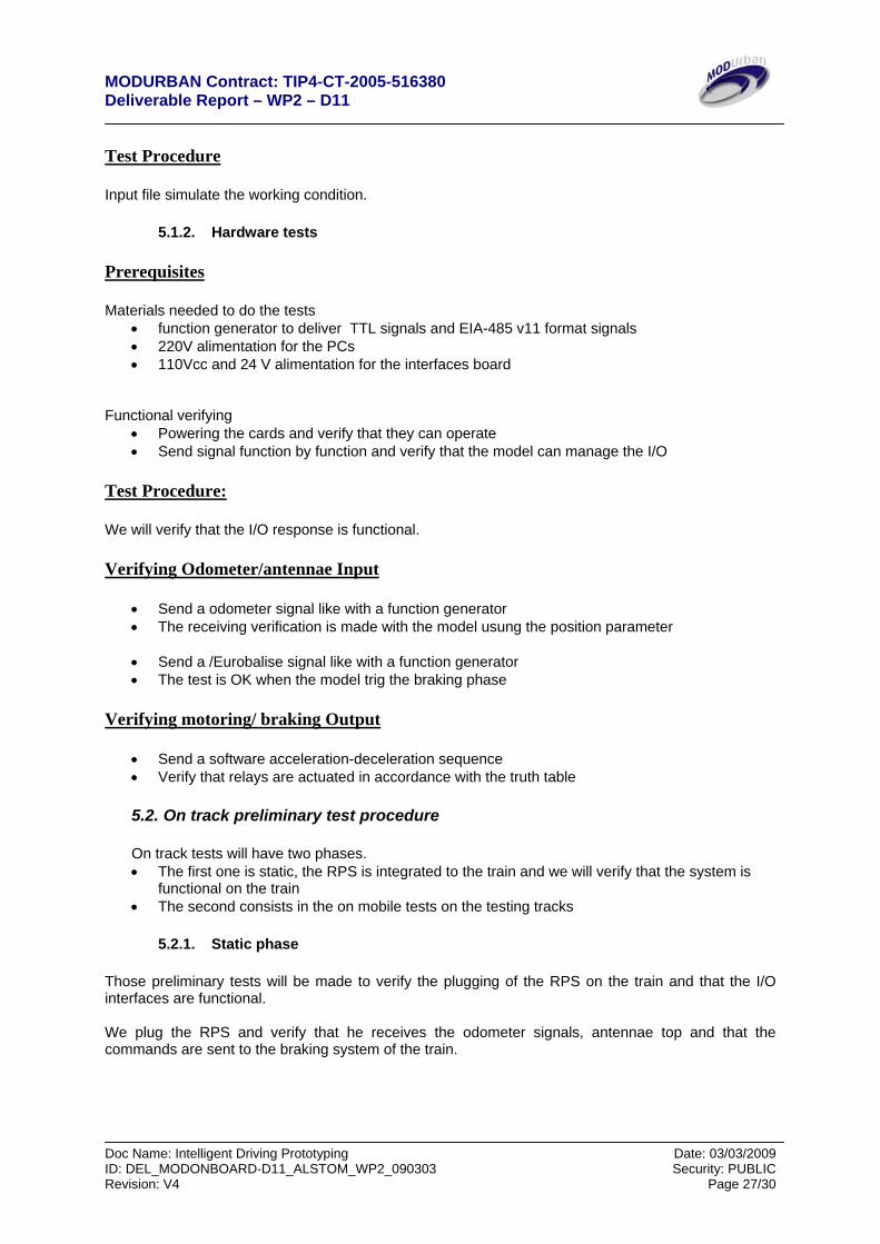
Test Procedure Input file simulate the working condition.
5.1.2. Hardware tests Prerequisites Materials needed to do the tests
• function generator to deliver TTL signals and EIA-485 v11 format signals • 220V alimentation for the PCs • 110Vcc and 24 V alimentation for the interfaces board
Functional verifying
• Powering the cards and verify that they can operate • Send signal function by function and verify that the model can manage the I/O
Test Procedure: We will verify that the I/O response is functional. Verifying Odometer/antennae Input
• Send a odometer signal like with a function generator • The receiving verification is made with the model usung the position parameter
• Send a /Eurobalise signal like with a function generator • The test is OK when the model trig the braking phase
Verifying motoring/ braking Output
• Send a software acceleration-deceleration sequence • Verify that relays are actuated in accordance with the truth table 5.2. On track preliminary test procedure
On track tests will have two phases. • The first one is static, the RPS is integrated to the train and we will verify that the system is
functional on the train • The second consists in the on mobile tests on the testing tracks
5.2.1. Static phase
Those preliminary tests will be made to verify the plugging of the RPS on the train and that the I/O interfaces are functional. We plug the RPS and verify that he receives the odometer signals, antennae top and that the commands are sent to the braking system of the train.
MODURBAN Contract: TIP4-CT-2005-516380 Deliverable Report – WP2 – D11
Doc Name: Intelligent Driving Prototyping Date: 03/03/2009 ID: DEL_MODONBOARD-D11_ALSTOM_WP2_090303 Security: PUBLIC Revision: V4 Page 28/30
5.2.2. On track tests
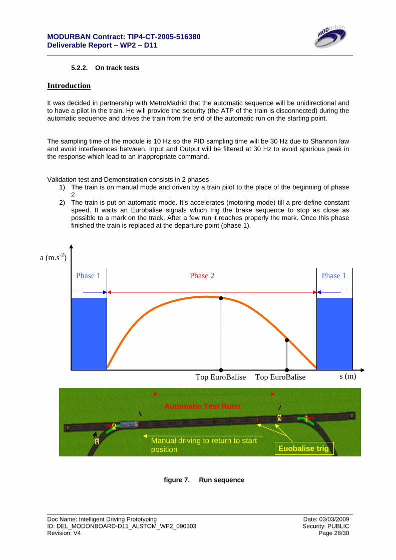
Introduction It was decided in partnership with MetroMadrid that the automatic sequence will be unidirectional and to have a pilot in the train. He will provide the security (the ATP of the train is disconnected) during the automatic sequence and drives the train from the end of the automatic run on the starting point. The sampling time of the module is 10 Hz so the PID sampling time will be 30 Hz due to Shannon law and avoid interferences between. Input and Output will be filtered at 30 Hz to avoid spurious peak in the response which lead to an inappropriate command. Validation test and Demonstration consists in 2 phases
1) The train is on manual mode and driven by a train pilot to the place of the beginning of phase 2
2) The train is put on automatic mode. It’s accelerates (motoring mode) till a pre-define constant speed. It waits an Eurobalise signals which trig the brake sequence to stop as close as possible to a mark on the track. After a few run it reaches properly the mark. Once this phase finished the train is replaced at the departure point (phase 1).
figure 7. Run sequence
Phase 1 Phase 1 Phase 2
Top EuroBalise s (m)
Automatic Test Runs
Manual driving to return to start position Euobalise trig
Top EuroBalise
a (m.s-2)
MODURBAN Contract: TIP4-CT-2005-516380 Deliverable Report – WP2 – D11
Doc Name: Intelligent Driving Prototyping Date: 03/03/2009 ID: DEL_MODONBOARD-D11_ALSTOM_WP2_090303 Security: PUBLIC Revision: V4 Page 29/30
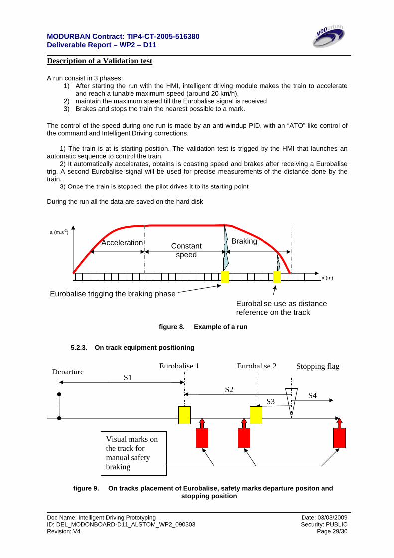
Description of a Validation test A run consist in 3 phases:
1) After starting the run with the HMI, intelligent driving module makes the train to accelerate and reach a tunable maximum speed (around 20 km/h),
2) maintain the maximum speed till the Eurobalise signal is received 3) Brakes and stops the train the nearest possible to a mark.
The control of the speed during one run is made by an anti windup PID, with an “ATO” like control of the command and Intelligent Driving corrections. 1) The train is at is starting position. The validation test is trigged by the HMI that launches an automatic sequence to control the train. 2) It automatically accelerates, obtains is coasting speed and brakes after receiving a Eurobalise trig. A second Eurobalise signal will be used for precise measurements of the distance done by the train. 3) Once the train is stopped, the pilot drives it to its starting point During the run all the data are saved on the hard disk
figure 8. Example of a run
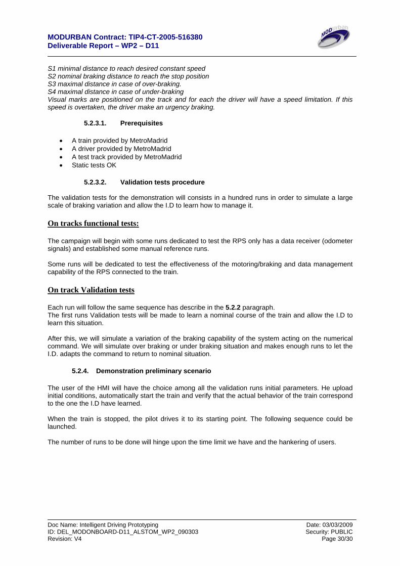
5.2.3. On track equipment positioning
figure 9. On tracks placement of Eurobalise, safety marks departure positon and
stopping position
a (m.s-2)
x (m)
Acceleration Constant speed
Braking
Eurobalise trigging the braking phase Eurobalise use as distance
reference on the track
S1S2
S3S4
Eurobalise 1 Eurobalise 2
Visual marks on the track for manual safety braking
DepartureStopping flag
MODURBAN Contract: TIP4-CT-2005-516380 Deliverable Report – WP2 – D11
Doc Name: Intelligent Driving Prototyping Date: 03/03/2009 ID: DEL_MODONBOARD-D11_ALSTOM_WP2_090303 Security: PUBLIC Revision: V4 Page 30/30
S1 minimal distance to reach desired constant speed S2 nominal braking distance to reach the stop position S3 maximal distance in case of over-braking. S4 maximal distance in case of under-braking Visual marks are positioned on the track and for each the driver will have a speed limitation. If this speed is overtaken, the driver make an urgency braking.
5.2.3.1. Prerequisites
• A train provided by MetroMadrid • A driver provided by MetroMadrid • A test track provided by MetroMadrid • Static tests OK
5.2.3.2. Validation tests procedure
The validation tests for the demonstration will consists in a hundred runs in order to simulate a large scale of braking variation and allow the I.D to learn how to manage it. On tracks functional tests: The campaign will begin with some runs dedicated to test the RPS only has a data receiver (odometer signals) and established some manual reference runs. Some runs will be dedicated to test the effectiveness of the motoring/braking and data management capability of the RPS connected to the train. On track Validation tests Each run will follow the same sequence has describe in the 5.2.2 paragraph. The first runs Validation tests will be made to learn a nominal course of the train and allow the I.D to learn this situation. After this, we will simulate a variation of the braking capability of the system acting on the numerical command. We will simulate over braking or under braking situation and makes enough runs to let the I.D. adapts the command to return to nominal situation.
5.2.4. Demonstration preliminary scenario The user of the HMI will have the choice among all the validation runs initial parameters. He upload initial conditions, automatically start the train and verify that the actual behavior of the train correspond to the one the I.D have learned. When the train is stopped, the pilot drives it to its starting point. The following sequence could be launched. The number of runs to be done will hinge upon the time limit we have and the hankering of users.