Embed Size (px)
Citation preview

Moldflow DesignGuide
Shoemaker
Moldflow Design Guide
The Moldflow Design Guide is intended to help practicing engineers solve problems they encounter
frequently in the design of parts and molds and during production. Today, the global imperative to
drive down the cost of manufacturing has led to the use of molding simulation as a cost optimization
tool rather than just as a design and problem avoidance tool. It is critical for engineers in the plastics
field to have access to flow analyses and their interpretations, including the simulation of cooling and
warp effects, to aid in the successful design and manufacture of parts and molds.
The book provides an overview of the polymer flow behavior and the injection molding process,
design principles to facilitate integrated part and mold design, and examples of how Moldflow design
analysis technology can be used both to solve problems and to optimize the design of part, mold, and
the molding process itself.
• Polymer Flow Behavior in Injection Molds
• Molding Conditions and Injection Pressure
• Filling Pattern
• Moldflow Design Principles
• Meshes Used In Moldflow Analyses
• Product Design
• Gate Design
• Runner System Design
• Cooling System Design
• Shrinkage and Warpage
• Moldflow Design Procedure
• Part Defects
Contents:
Jay Shoemaker (Ed.)
A Resource for Plastics Engineers
ISBN-10: 3-446-40640-9
ISBN-13: 978-3-446-40640-7
Carl Hanser Verlag
www.hanser.de
ISBN-10: 1-56990-403-0
ISBN-13: 978-1-56990-403-9
Hanser Gardner Publications
www.hansergardner.com
Sh
oem
aker
Mo
ldflo
wD
esig
nG
uid
e
9 781569 904039

Jay Shoemaker (Editor)Moldflow Design Guide


Moldflow DesignGuideA Resource for Plastics Engineers
Jay Shoemaker (Editor)
Hanser Publishers, Munich • Hanser Gardner Publications, Cincinnati

The Editor:Jay Shoemaker, Moldflow Corporation, Framingham, Massachusetts, USA
Distributed in the USA and in Canada byHanser Gardner Publications, Inc.6915 Valley Avenue, Cincinnati, Ohio 45244-3029, USAFax: (513) 527-8801Phone: (513) 527-8977 or 1-800-950-8977www.hansergardner.com
Distributed in all other countries byCarl Hanser VerlagPostfach 86 04 20, 81631 München, GermanyFax: +49 (89) 98 48 09www.hanser.de
The use of general descriptive names, trademarks, etc., in this publication, even if the former are not especially identified, is not to be taken as a sign that such names, as understood by the Trade Marks and Merchandise Marks Act, may accordingly be used freely by anyone.While the advice and information in this book are believed to be true and accurate at the date of going to press, neither the authors nor the editors nor the publisher can accept any legal responsibility for any errors or omissions that may be made. The publisher makes no warranty, express or implied, with respect to the material contained herein.
Library of Congress Cataloging-in-Publication Data
Shoemaker, Jay. Moldflow design guide : a resource for plastic engineers / Jay Shoemaker. p. cm. ISBN-13: 978-1-56990-403-9 (hardcover) ISBN-10: 1-56990-403-0 (hardcover)1. Injection molding of plastics. I. Title. TP1120.S486 2006 668.4‘12--dc22 2006012438
Bibliografische Information Der Deutschen BibliothekDie Deutsche Bibliothek verzeichnet diese Publikation in der Deutschen Nationalbibliografie;detaillierte bibliografische Daten sind im Internet über <http://dnb.ddb.de> abrufbar.
ISBN-10: 3-446-40640-9ISBN-13: 978-3-446-40640-7
All rights reserved. No part of this book may be reproduced or transmitted in any form or by any means, electronic ormechanical, including photocopying or by any information storage and retrieval system, without permission in writing from the publisher.
© Moldflow Corporation, USA 2006Production Management: Oswald ImmelTypeset by Marcia Swan, USACoverconcept: Marc Müller-Bremer, Rebranding, München, GermanyCoverdesign: MCP • Susanne Kraus GbR, Holzkirchen, GermanyPrinted and bound by Kösel, Krugzell, Germany
Foreword
The drive toward fast, cost-effective, and reliable plastics manufacturing has been Moldflow�ssole guiding goal since the company was founded over 25 years ago.This focused determination led us to introduce many new and exciting tools into the market,each contributing to achieving our goal in some way, whether by driving cost out ofproduction with reduced material usage or shortened cycle times, reducing mold delivery timeby minimizing re-work, or increasing the reliability of supply by enabling higher qualityproducts to be manufactured with greater surety in scheduling.The artificially balanced, multi-cavity and family molds that are now commonplace were madepractical through the advent of our early simulation and runner balancing capabilities, whichwere introduced in the late 1970s and early 1980s. As these tools evolved, we were able tovisualize, and therefore control, flow patterns and weld lines. This evolution continued untilwe arrived in the 2000s with an array of sophisticated technology to control warpage, accountfor heat transfer, predict core shift, adapt to new molding processes, and much more. Fromtraditional midplane technology to fully three-dimensional simulations, all our solutions arewell integrated into a solid-modeling design environment. As the technology has evolved, so has its usage. When Moldflow simulation technology wasintroduced, its primary purpose was to search for remedies to pre-existing molding problems.It soon became evident that the insight the software provided to solve molding problemswould be better applied ahead of actual molding, during the design process. Thismethodology, which we call �problem avoidance,� was the primary use for Moldflowtechnology for the first 20 years of its existence.For Moldflow, this created a unique challenge: to open the world of manufacturing to thedesigners of parts and molds. What constitutes an ineffective design for molding may beapparent to a seasoned processing engineer looking retrospectively at a poorly performingtool, but how can design engineers use the CAE tools to visualize, diagnose and solve thesesame issues ahead of time�without 20 years of molding experience? How can manufacturersgo further and use information that cannot be seen in the real molding process but is revealedvia simulation?The key that unlocked this puzzle began its life as the Moldflow Design Philosophy. This is widelyviewed as the most important publication Moldflow has ever produced and has spawnedfollow-on works on related subjects. Rather than provide insight into the operation of thesimulation tools, Moldflow Design Philosophy set forth simple principles that transcend anyspecific software application and, as a result, are as valid with today's advanced simulationproducts as they were over two decades ago.In more recent years, another transition has occurred. The global imperative to drive down thecost of manufacturing has led to the use of molding simulation as a cost optimization toolrather than for problem avoidance. This change has increased the number of Moldflow usersby an order of magnitude across a far broader cross-section of the plastics industry. Greaterdesign-centricity leads to even more dependence on the plastics design principles, which canbe used to drive optimization.

VI Foreword
Despite a quarter of a century of technological advances, the golden years of CAE are aheadof us as our industry takes a broader and more integrated view of what it takes to manage aproduct�s life cycle. Moldflow is proud of its contributions to date and will continue to focuson developing innovative technology coupled with practical design principles to deliver moreprofitable manufacturing.
Roland ThomasPresident & CEO, Moldflow Corporation
Preface VII
Preface
About this Book
The origins of this book include not only Moldflow Design Principles, but also Warpage DesignPrinciples published by Moldflow, and the C-MOLD Design Guide. Collectively, thesedocuments are based on years of experience in the research, theory, and practice of injectionmolding. These documents are now combined into this book: the Moldflow Design Guide. TheMoldflow Design Guide is intended to help practicing engineers solve problems they frequentlyencounter in the design of parts and molds, as well as during production. This book can alsobe used as a reference for training purposes at industrial and educational institutions.
How to Use this Book
This book has several chapters and appendices that deal with different stages of the designprocess and provides background on the injection-molding process and plastic materials.• The first three chapters introduce injection molding how polymers flow inside injection
molds and how molding conditions and injection pressure influence the process.• Chapter 4 discusses Moldflow design principles and how they relate to making quality
parts.• Chapter 5 introduces the finite element mesh technology used by Moldflow and how these
meshes influence the quality of the analysis. • Chapters 6 to 9 introduce design concepts for the product, gates, runners, and cooling
systems.• Chapter 10 introduces concepts relating to shrinkage and warpage and how Moldflow is
used to determine the amount of shrinkage and warpage a molded part will have and whatcauses the warpage.
• Chapter 11 discusses the design procedure for analyzing injection-molded parts.• Chapter 12 discusses major part defects found on injection-molded parts.• Finally the four appendices discuss basic injection-molding machine operation, process
control, variants of the standard injection-molding process, and plastic materials.
Benefits of Using CAE
The injection-molding industry has recognized that computer-aided engineering (CAE)enhances an engineer's ability to handle all aspects of the polymer injection-molding process,benefiting productivity, product quality, timeliness, and cost. This is illustrated by a wealth of

VIII Preface
literature and the ever-growing number of CAE software users in the injection-moldingindustry.
CAE Predicts Process Behavior
Ideally, CAE analysis provides insight that is useful in designing parts, molds, and moldingprocesses. Without it, we rely on previous experience, intuition, prototyping, or molding trialsto obtain information such as polymer melt filling patterns, weld-line and air-trap locations,required injection pressure and clamp tonnage, fiber orientation, cycle time, final part shapeand deformation, and mechanical properties of molded parts, just to name a few. WithoutCAE analysis, other equally important design data, such as spatial distributions of pressure,temperature, shear rate, shear stress, and velocity, are more difficult to obtain, even with awell-instrumented mold. The process behavior predicted by CAE can help novice engineersovercome the lack of previous experience and assist experienced engineers in pinpointingfactors that may otherwise be overlooked. By using CAE analysis to iterate and evaluatealternative designs and competing materials, engineering know-how in the form of designguidelines can be established relatively faster and more cost-effectively.
User Proficiency Determines the Benefits of CAE
While CAE technology helps save time, money, and raw material, as well as cuts scrap, reducesthe rejection rate, improves product quality, and gets new products to market faster, it is by nomeans a panacea for solving all molding problems. Rather, it should be recognized that CAEanalysis is essentially a tool, designed to assist engineers instead of taking over theirresponsibilities or replacing them. Like many other tools, the usefulness of CAE technologydepends on the proficiency of the user. The benefits mentioned above will not be realizedunless the CAE tool is used properly. To be more specific, the accuracy of CAE analysisdepends greatly on the input data provided by the user. In addition, the results generated byCAE analysis need to be correctly and intelligently interpreted by the user before soundjudgments and rational decisions are made. Otherwise, users will simply be swamped by thevast amount of data without getting any useful information.

Acknowledgements IX
Acknowledgements
The Moldflow Design Guide would not have been accomplished were it not for the vision of KenWelch. Ken and I have discussed the value of assembling the best of the Moldflow DesignPrinciples, Warpage Design Principles, and the C-MOLD Design Guide into a single book for severalyears. With Ken's leadership, he gave the project to Steve Thompson's training group, ofwhich I am a part. Steve helped me coordinate the resources necessary to get this projectdone. I could not have done this project without Steve's help and guidance. A review of the content was part of the development of the Moldflow Design Guide. Moldflowdevelopers including Peter Kennedy, Rong Zheng, Zhongshuang Yuan, and Xiaoshi Jin havereviewed sections of the book. Moldflow's application engineers and other technical staff withMoldflow have also reviewed sections. These reviewers include Chad Fuhrman, Matt Jaworski,Christine Roedlich, Eric Henry, Olivier Anninos, Paul Larter, and Ana Maria Marin. A specialthanks goes to Mike Rogers, who reviewed the entire book for me and provided criticalfeedback on the content and organization of the book. I would also like to thank Kurt Haydenof Western Michigan University for reviewing the appendix on process control. His manyyears of experience of process setup and optimization was invaluable.Finally, I would like to thank members of Moldflow's Technology Transfer group forsupporting me in the writing of this book. These members include Marcia Swan, CarolineDorin, Robert Ashley, Melissa Haslam, Darren Seamons, and Gregory Brown.On a personal note, I would like to acknowledge and thank Paul Engelmann, Professor andDepartment Chair, Western Michigan University, Department of Industrial and ManufacturingEngineering, for being my friend and mentor during my career. With Paul, I have been able toteach and participate in research he has done on injection molding tooling and processing atWestern Michigan University. I have found working with Paul has made me a better Moldflowuser and engineer by providing another perspective on how Moldflow can be used to solveinjection molding problems.Jay Shoemaker, Editor

Contents
1 Polymer Flow Behavior in Injection Molds . . . . . . . . . . . . . . . . . . . . . . . . 1
1.1 Phases of Injection Molding . . . . . . . . . . . . . . . . . . . . . . . . . . . . . . . . . . . . . . . . . 11.1.1 How Plastic Fills a Mold . . . . . . . . . . . . . . . . . . . . . . . . . . . . . . . . . . . . . . . . . . . . 11.1.2 The Filling Phase . . . . . . . . . . . . . . . . . . . . . . . . . . . . . . . . . . . . . . . . . . . . . . . . . . 31.1.3 The Pressurization Phase . . . . . . . . . . . . . . . . . . . . . . . . . . . . . . . . . . . . . . . . . . . . 61.1.4 The Compensation Phase . . . . . . . . . . . . . . . . . . . . . . . . . . . . . . . . . . . . . . . . . . . 61.2 How Do Plastics Flow? . . . . . . . . . . . . . . . . . . . . . . . . . . . . . . . . . . . . . . . . . . . . . 71.2.1 Material Behavior . . . . . . . . . . . . . . . . . . . . . . . . . . . . . . . . . . . . . . . . . . . . . . . . . . 71.2.2 Deformation . . . . . . . . . . . . . . . . . . . . . . . . . . . . . . . . . . . . . . . . . . . . . . . . . . . . . . 81.2.3 Viscoelastic Behavior . . . . . . . . . . . . . . . . . . . . . . . . . . . . . . . . . . . . . . . . . . . . . . . 81.2.4 Melt Shear Viscosity . . . . . . . . . . . . . . . . . . . . . . . . . . . . . . . . . . . . . . . . . . . . . . . . 91.2.5 Newtonian Fluid vs. Non-Newtonian Fluid . . . . . . . . . . . . . . . . . . . . . . . . . . . . 101.2.6 Shear-thinning Behavior . . . . . . . . . . . . . . . . . . . . . . . . . . . . . . . . . . . . . . . . . . . . 101.2.7 Shear Rate Distribution . . . . . . . . . . . . . . . . . . . . . . . . . . . . . . . . . . . . . . . . . . . . 111.2.8 Pressure-driven Flow . . . . . . . . . . . . . . . . . . . . . . . . . . . . . . . . . . . . . . . . . . . . . . 111.2.9 Pressure Gradient and Injection Times . . . . . . . . . . . . . . . . . . . . . . . . . . . . . . . . 131.2.10 Melt Flow Length . . . . . . . . . . . . . . . . . . . . . . . . . . . . . . . . . . . . . . . . . . . . . . . . . 131.2.11 Injection Pressure vs. Fill Time . . . . . . . . . . . . . . . . . . . . . . . . . . . . . . . . . . . . . . 131.2.12 Flow Instability . . . . . . . . . . . . . . . . . . . . . . . . . . . . . . . . . . . . . . . . . . . . . . . . . . . 15
2 Molding Conditions and Injection Pressure . . . . . . . . . . . . . . . . . . . . . . 17
2.1 Injection-pressure Overview . . . . . . . . . . . . . . . . . . . . . . . . . . . . . . . . . . . . . . . . 172.1.1 Pressure Drives the Flow Front . . . . . . . . . . . . . . . . . . . . . . . . . . . . . . . . . . . . . . 182.2 Factors Influencing Injection-pressure Requirements . . . . . . . . . . . . . . . . . . . . 182.3 Equations . . . . . . . . . . . . . . . . . . . . . . . . . . . . . . . . . . . . . . . . . . . . . . . . . . . . . . . 202.3.1 Circular Channel Flow . . . . . . . . . . . . . . . . . . . . . . . . . . . . . . . . . . . . . . . . . . . . . 202.3.2 Strip Channel Flow. . . . . . . . . . . . . . . . . . . . . . . . . . . . . . . . . . . . . . . . . . . . . . . . 202.4 Effect of Molding Conditions . . . . . . . . . . . . . . . . . . . . . . . . . . . . . . . . . . . . . . . 212.4.1 Part Quality . . . . . . . . . . . . . . . . . . . . . . . . . . . . . . . . . . . . . . . . . . . . . . . . . . . . . . 212.4.2 Melt Temperature . . . . . . . . . . . . . . . . . . . . . . . . . . . . . . . . . . . . . . . . . . . . . . . . . 222.4.3 Mold Temperature . . . . . . . . . . . . . . . . . . . . . . . . . . . . . . . . . . . . . . . . . . . . . . . . 222.4.4 Fill Time . . . . . . . . . . . . . . . . . . . . . . . . . . . . . . . . . . . . . . . . . . . . . . . . . . . . . . . . 232.4.5 Shear Stress Variation . . . . . . . . . . . . . . . . . . . . . . . . . . . . . . . . . . . . . . . . . . . . . . 232.4.6 Packing Pressure and Time . . . . . . . . . . . . . . . . . . . . . . . . . . . . . . . . . . . . . . . . . 242.4.7 Summary . . . . . . . . . . . . . . . . . . . . . . . . . . . . . . . . . . . . . . . . . . . . . . . . . . . . . . . . 252.4.8 Back Flow . . . . . . . . . . . . . . . . . . . . . . . . . . . . . . . . . . . . . . . . . . . . . . . . . . . . . . . 262.5 Using Moldflow to Determine Optimum Molding Conditions . . . . . . . . . . . . . 262.5.1 Part . . . . . . . . . . . . . . . . . . . . . . . . . . . . . . . . . . . . . . . . . . . . . . . . . . . . . . . . . . . . 272.5.2 Molding Window Size . . . . . . . . . . . . . . . . . . . . . . . . . . . . . . . . . . . . . . . . . . . . . 272.5.3 Injection Pressure . . . . . . . . . . . . . . . . . . . . . . . . . . . . . . . . . . . . . . . . . . . . . . . . . 282.5.4 Flow Front Temperature . . . . . . . . . . . . . . . . . . . . . . . . . . . . . . . . . . . . . . . . . . . 29
XII Contents
2.5.5 Cooling Time . . . . . . . . . . . . . . . . . . . . . . . . . . . . . . . . . . . . . . . . . . . . . . . . . . . . 302.5.6 Summary . . . . . . . . . . . . . . . . . . . . . . . . . . . . . . . . . . . . . . . . . . . . . . . . . . . . . . . . 31
3 Filling Pattern . . . . . . . . . . . . . . . . . . . . . . . . . . . . . . . . . . . . . . . . . . . . . . 33
3.1 Filling Pattern Overview . . . . . . . . . . . . . . . . . . . . . . . . . . . . . . . . . . . . . . . . . . . 333.1.1 What Is the Filling Pattern? . . . . . . . . . . . . . . . . . . . . . . . . . . . . . . . . . . . . . . . . . 333.2 Flow in Complex Molds. . . . . . . . . . . . . . . . . . . . . . . . . . . . . . . . . . . . . . . . . . . . 343.2.1 Overpack. . . . . . . . . . . . . . . . . . . . . . . . . . . . . . . . . . . . . . . . . . . . . . . . . . . . . . . . 343.2.2 Racetrack Effect . . . . . . . . . . . . . . . . . . . . . . . . . . . . . . . . . . . . . . . . . . . . . . . . . . 353.2.3 Varying Injection Rate . . . . . . . . . . . . . . . . . . . . . . . . . . . . . . . . . . . . . . . . . . . . . 353.2.4 Underflow Effect . . . . . . . . . . . . . . . . . . . . . . . . . . . . . . . . . . . . . . . . . . . . . . . . . 363.2.5 Hesitation Effect . . . . . . . . . . . . . . . . . . . . . . . . . . . . . . . . . . . . . . . . . . . . . . . . . 373.2.6 Weld Lines. . . . . . . . . . . . . . . . . . . . . . . . . . . . . . . . . . . . . . . . . . . . . . . . . . . . . . . 383.2.7 Meld Lines. . . . . . . . . . . . . . . . . . . . . . . . . . . . . . . . . . . . . . . . . . . . . . . . . . . . . . . 383.2.8 Sink Marks . . . . . . . . . . . . . . . . . . . . . . . . . . . . . . . . . . . . . . . . . . . . . . . . . . . . . . 383.2.9 Multidirectional Flow . . . . . . . . . . . . . . . . . . . . . . . . . . . . . . . . . . . . . . . . . . . . . . 393.2.10 Unstable Flow. . . . . . . . . . . . . . . . . . . . . . . . . . . . . . . . . . . . . . . . . . . . . . . . . . . . 403.2.11 Simple Flow Pattern . . . . . . . . . . . . . . . . . . . . . . . . . . . . . . . . . . . . . . . . . . . . . . . 413.3 Flow-front Velocity and Flow-front Area . . . . . . . . . . . . . . . . . . . . . . . . . . . . . . 413.3.1 What are FFV and FFA? . . . . . . . . . . . . . . . . . . . . . . . . . . . . . . . . . . . . . . . . . . . 413.3.2 Flow-front Velocity Influences Filling Pattern . . . . . . . . . . . . . . . . . . . . . . . . . . 413.3.3 Equation . . . . . . . . . . . . . . . . . . . . . . . . . . . . . . . . . . . . . . . . . . . . . . . . . . . . . . . . 423.4 Using Moldflow to Determine the Filling Pattern . . . . . . . . . . . . . . . . . . . . . . . 433.4.1 Computer Simulation Can Eliminate Molding Trials . . . . . . . . . . . . . . . . . . . . . 433.4.2 Using a Flow Analysis . . . . . . . . . . . . . . . . . . . . . . . . . . . . . . . . . . . . . . . . . . . . . 433.5 Using Moldflow to Achieve Constant FFV . . . . . . . . . . . . . . . . . . . . . . . . . . . . 443.5.1 Controlling the FFV Through Ram Speed . . . . . . . . . . . . . . . . . . . . . . . . . . . . . 44
4 Moldflow Design Principles . . . . . . . . . . . . . . . . . . . . . . . . . . . . . . . . . . . 47
4.1 Product Design and Moldflow. . . . . . . . . . . . . . . . . . . . . . . . . . . . . . . . . . . . . . . 474.2 Sequence of Analysis . . . . . . . . . . . . . . . . . . . . . . . . . . . . . . . . . . . . . . . . . . . . . . 474.2.1 Part Filling Optimization . . . . . . . . . . . . . . . . . . . . . . . . . . . . . . . . . . . . . . . . . . . 484.2.2 Molding Conditions . . . . . . . . . . . . . . . . . . . . . . . . . . . . . . . . . . . . . . . . . . . . . . . 484.2.3 Runner Design . . . . . . . . . . . . . . . . . . . . . . . . . . . . . . . . . . . . . . . . . . . . . . . . . . . 484.2.4 Cooling Optimization. . . . . . . . . . . . . . . . . . . . . . . . . . . . . . . . . . . . . . . . . . . . . . 494.2.5 Packing Optimization . . . . . . . . . . . . . . . . . . . . . . . . . . . . . . . . . . . . . . . . . . . . . . 494.2.6 Warpage Optimization . . . . . . . . . . . . . . . . . . . . . . . . . . . . . . . . . . . . . . . . . . . . . 494.3 Moldflow Flow Concepts. . . . . . . . . . . . . . . . . . . . . . . . . . . . . . . . . . . . . . . . . . . 494.3.1 Unidirectional and Controlled Flow Pattern . . . . . . . . . . . . . . . . . . . . . . . . . . . . 504.3.2 Flow Balancing . . . . . . . . . . . . . . . . . . . . . . . . . . . . . . . . . . . . . . . . . . . . . . . . . . . 514.3.3 Constant Pressure Gradient . . . . . . . . . . . . . . . . . . . . . . . . . . . . . . . . . . . . . . . . . 524.3.4 Maximum Shear Stress . . . . . . . . . . . . . . . . . . . . . . . . . . . . . . . . . . . . . . . . . . . . . 534.3.5 Uniform Cooling . . . . . . . . . . . . . . . . . . . . . . . . . . . . . . . . . . . . . . . . . . . . . . . . . 54

Contents XIII
4.3.6 Positioning Weld and Meld Lines . . . . . . . . . . . . . . . . . . . . . . . . . . . . . . . . . . . . 554.3.7 Avoid Hesitation Effects . . . . . . . . . . . . . . . . . . . . . . . . . . . . . . . . . . . . . . . . . . . 554.3.8 Avoid Underflow . . . . . . . . . . . . . . . . . . . . . . . . . . . . . . . . . . . . . . . . . . . . . . . . . 554.3.9 Balancing with Flow Leaders and Flow Deflectors . . . . . . . . . . . . . . . . . . . . . . 574.3.10 Controlled Frictional Heat . . . . . . . . . . . . . . . . . . . . . . . . . . . . . . . . . . . . . . . . . . 584.3.11 Thermal Shutoff of Runners . . . . . . . . . . . . . . . . . . . . . . . . . . . . . . . . . . . . . . . . 584.3.12 Acceptable Runner/Cavity Ratio . . . . . . . . . . . . . . . . . . . . . . . . . . . . . . . . . . . . . 59
5 Meshes Used In Moldflow Analyses . . . . . . . . . . . . . . . . . . . . . . . . . . . . 61
5.1 Mesh Types Used by Moldflow . . . . . . . . . . . . . . . . . . . . . . . . . . . . . . . . . . . . . . 615.1.1 Finite Elements Used in Moldflow . . . . . . . . . . . . . . . . . . . . . . . . . . . . . . . . . . . 615.1.2 Mesh Types . . . . . . . . . . . . . . . . . . . . . . . . . . . . . . . . . . . . . . . . . . . . . . . . . . . . . . 625.1.3 Solver Assumptions . . . . . . . . . . . . . . . . . . . . . . . . . . . . . . . . . . . . . . . . . . . . . . . 635.2 Mesh Requirements . . . . . . . . . . . . . . . . . . . . . . . . . . . . . . . . . . . . . . . . . . . . . . . 645.2.1 Mesh Density Considerations . . . . . . . . . . . . . . . . . . . . . . . . . . . . . . . . . . . . . . . 645.2.2 Part Details . . . . . . . . . . . . . . . . . . . . . . . . . . . . . . . . . . . . . . . . . . . . . . . . . . . . . . 675.3 Geometry Creation . . . . . . . . . . . . . . . . . . . . . . . . . . . . . . . . . . . . . . . . . . . . . . . . 685.4 Importing Geometry . . . . . . . . . . . . . . . . . . . . . . . . . . . . . . . . . . . . . . . . . . . . . . 695.5 Using Different Mesh Types . . . . . . . . . . . . . . . . . . . . . . . . . . . . . . . . . . . . . . . . 695.5.1 Door Panel . . . . . . . . . . . . . . . . . . . . . . . . . . . . . . . . . . . . . . . . . . . . . . . . . . . . . . 695.5.2 Manifold . . . . . . . . . . . . . . . . . . . . . . . . . . . . . . . . . . . . . . . . . . . . . . . . . . . . . . . . 70
6 Product Design . . . . . . . . . . . . . . . . . . . . . . . . . . . . . . . . . . . . . . . . . . . . . 71
6.1 Material Properties for Product Design. . . . . . . . . . . . . . . . . . . . . . . . . . . . . . . . 716.1.1 Plastics Are Sensitive to Operating Conditions. . . . . . . . . . . . . . . . . . . . . . . . . . 716.1.2 Stress-Strain Behavior. . . . . . . . . . . . . . . . . . . . . . . . . . . . . . . . . . . . . . . . . . . . . . 726.1.3 Creep and Stress Relaxation . . . . . . . . . . . . . . . . . . . . . . . . . . . . . . . . . . . . . . . . . 776.1.4 Fatigue . . . . . . . . . . . . . . . . . . . . . . . . . . . . . . . . . . . . . . . . . . . . . . . . . . . . . . . . . . 796.1.5 Impact strength. . . . . . . . . . . . . . . . . . . . . . . . . . . . . . . . . . . . . . . . . . . . . . . . . . . 806.1.6 Thermal Mechanical Behavior . . . . . . . . . . . . . . . . . . . . . . . . . . . . . . . . . . . . . . . 806.2 Design for Strength . . . . . . . . . . . . . . . . . . . . . . . . . . . . . . . . . . . . . . . . . . . . . . . 826.2.1 Predicting Part Strength . . . . . . . . . . . . . . . . . . . . . . . . . . . . . . . . . . . . . . . . . . . . 826.2.2 Loading/Operating Conditions . . . . . . . . . . . . . . . . . . . . . . . . . . . . . . . . . . . . . . 826.3 Part Thickness. . . . . . . . . . . . . . . . . . . . . . . . . . . . . . . . . . . . . . . . . . . . . . . . . . . . 866.3.1 Part Thickness Drives Quality and Cost . . . . . . . . . . . . . . . . . . . . . . . . . . . . . . . 866.3.2 Cycle Time Increases with Thickness . . . . . . . . . . . . . . . . . . . . . . . . . . . . . . . . . 866.3.3 Thick Parts Tend to Warp . . . . . . . . . . . . . . . . . . . . . . . . . . . . . . . . . . . . . . . . . . 866.3.4 Thin, Uniform Parts Improve Surface Quality . . . . . . . . . . . . . . . . . . . . . . . . . . 876.3.5 Reducing Part Thickness . . . . . . . . . . . . . . . . . . . . . . . . . . . . . . . . . . . . . . . . . . . 876.4 Boosting Structural Integrity with Ribs . . . . . . . . . . . . . . . . . . . . . . . . . . . . . . . . 886.4.1 Structural Integrity: the Goal of Every Design. . . . . . . . . . . . . . . . . . . . . . . . . . 886.4.2 Designing Ribs . . . . . . . . . . . . . . . . . . . . . . . . . . . . . . . . . . . . . . . . . . . . . . . . . . . 88
XIV Contents
6.5 Design for Assembly . . . . . . . . . . . . . . . . . . . . . . . . . . . . . . . . . . . . . . . . . . . . . . 906.5.1 Molding One Part vs. Separate Components . . . . . . . . . . . . . . . . . . . . . . . . . . . 906.5.2 Tolerances: Fit between Parts. . . . . . . . . . . . . . . . . . . . . . . . . . . . . . . . . . . . . . . . 906.5.3 Press-fit Joints . . . . . . . . . . . . . . . . . . . . . . . . . . . . . . . . . . . . . . . . . . . . . . . . . . . . 916.5.4 Snap-fit Joints . . . . . . . . . . . . . . . . . . . . . . . . . . . . . . . . . . . . . . . . . . . . . . . . . . . . 936.5.5 Cantilever Snap Joints. . . . . . . . . . . . . . . . . . . . . . . . . . . . . . . . . . . . . . . . . . . . . . 956.5.6 Torsion Snap-fit Joints . . . . . . . . . . . . . . . . . . . . . . . . . . . . . . . . . . . . . . . . . . . . . 966.5.7 Fasteners . . . . . . . . . . . . . . . . . . . . . . . . . . . . . . . . . . . . . . . . . . . . . . . . . . . . . . . . 986.5.8 Inserts . . . . . . . . . . . . . . . . . . . . . . . . . . . . . . . . . . . . . . . . . . . . . . . . . . . . . . . . . 1016.5.9 Welding Processes. . . . . . . . . . . . . . . . . . . . . . . . . . . . . . . . . . . . . . . . . . . . . . . . 101
7 Gate Design . . . . . . . . . . . . . . . . . . . . . . . . . . . . . . . . . . . . . . . . . . . . . . . 103
7.1 Gate Design Overview . . . . . . . . . . . . . . . . . . . . . . . . . . . . . . . . . . . . . . . . . . . . 1037.1.1 What Is a Gate? . . . . . . . . . . . . . . . . . . . . . . . . . . . . . . . . . . . . . . . . . . . . . . . . . 1037.1.2 Single vs. Multiple Gates . . . . . . . . . . . . . . . . . . . . . . . . . . . . . . . . . . . . . . . . . . 1037.1.3 Gate Dimensions . . . . . . . . . . . . . . . . . . . . . . . . . . . . . . . . . . . . . . . . . . . . . . . . 1037.1.4 Gate Location . . . . . . . . . . . . . . . . . . . . . . . . . . . . . . . . . . . . . . . . . . . . . . . . . . . 1047.2 Gate Types . . . . . . . . . . . . . . . . . . . . . . . . . . . . . . . . . . . . . . . . . . . . . . . . . . . . . 1047.2.1 Manually Trimmed Gates . . . . . . . . . . . . . . . . . . . . . . . . . . . . . . . . . . . . . . . . . . 1047.2.2 Automatically Trimmed Gates . . . . . . . . . . . . . . . . . . . . . . . . . . . . . . . . . . . . . . 1107.3 Design Rules . . . . . . . . . . . . . . . . . . . . . . . . . . . . . . . . . . . . . . . . . . . . . . . . . . . . 1137.3.1 Determining the Number of Gates . . . . . . . . . . . . . . . . . . . . . . . . . . . . . . . . . . 1137.3.2 Flow Patterns . . . . . . . . . . . . . . . . . . . . . . . . . . . . . . . . . . . . . . . . . . . . . . . . . . . 1157.3.3 Gate Position . . . . . . . . . . . . . . . . . . . . . . . . . . . . . . . . . . . . . . . . . . . . . . . . . . . 1167.3.4 Avoiding Common Problems . . . . . . . . . . . . . . . . . . . . . . . . . . . . . . . . . . . . . . 1227.3.5 Gate Length . . . . . . . . . . . . . . . . . . . . . . . . . . . . . . . . . . . . . . . . . . . . . . . . . . . . 1227.3.6 Gate Thickness . . . . . . . . . . . . . . . . . . . . . . . . . . . . . . . . . . . . . . . . . . . . . . . . . . 1227.3.7 Freeze-off Time . . . . . . . . . . . . . . . . . . . . . . . . . . . . . . . . . . . . . . . . . . . . . . . . . 1237.4 Using Moldflow for Gate Design . . . . . . . . . . . . . . . . . . . . . . . . . . . . . . . . . . . 1237.4.1 Gate Location . . . . . . . . . . . . . . . . . . . . . . . . . . . . . . . . . . . . . . . . . . . . . . . . . . . 1237.4.2 Molding Window Size for the Three Gate Locations. . . . . . . . . . . . . . . . . . . . 1247.4.3 Filling Pattern . . . . . . . . . . . . . . . . . . . . . . . . . . . . . . . . . . . . . . . . . . . . . . . . . . . 1257.4.4 Gate Size Based on Shear Rate . . . . . . . . . . . . . . . . . . . . . . . . . . . . . . . . . . . . . 125
8 Runner System Design . . . . . . . . . . . . . . . . . . . . . . . . . . . . . . . . . . . . . . 127
8.1 Definitions . . . . . . . . . . . . . . . . . . . . . . . . . . . . . . . . . . . . . . . . . . . . . . . . . . . . . 1278.1.1 Feed System . . . . . . . . . . . . . . . . . . . . . . . . . . . . . . . . . . . . . . . . . . . . . . . . . . . . 1278.1.2 Runner System . . . . . . . . . . . . . . . . . . . . . . . . . . . . . . . . . . . . . . . . . . . . . . . . . . 1278.1.3 Cold Runner . . . . . . . . . . . . . . . . . . . . . . . . . . . . . . . . . . . . . . . . . . . . . . . . . . . . 1278.1.4 Hot Runner . . . . . . . . . . . . . . . . . . . . . . . . . . . . . . . . . . . . . . . . . . . . . . . . . . . . . 1288.1.5 Hot Manifold . . . . . . . . . . . . . . . . . . . . . . . . . . . . . . . . . . . . . . . . . . . . . . . . . . . 1288.1.6 Hot Drop . . . . . . . . . . . . . . . . . . . . . . . . . . . . . . . . . . . . . . . . . . . . . . . . . . . . . . 1288.1.7 Sprue . . . . . . . . . . . . . . . . . . . . . . . . . . . . . . . . . . . . . . . . . . . . . . . . . . . . . . . . . . 128

Contents XV
8.2 Runner System Design Principles . . . . . . . . . . . . . . . . . . . . . . . . . . . . . . . . . . . 1298.2.1 Benefits of Good Runner Design . . . . . . . . . . . . . . . . . . . . . . . . . . . . . . . . . . . 1298.2.2 Runner Design Philosophy. . . . . . . . . . . . . . . . . . . . . . . . . . . . . . . . . . . . . . . . . 1298.2.3 Flow Balancing . . . . . . . . . . . . . . . . . . . . . . . . . . . . . . . . . . . . . . . . . . . . . . . . . . 1308.2.4 Flow Control. . . . . . . . . . . . . . . . . . . . . . . . . . . . . . . . . . . . . . . . . . . . . . . . . . . . 1308.2.5 Frictional Heating in Runners . . . . . . . . . . . . . . . . . . . . . . . . . . . . . . . . . . . . . . 1328.2.6 Thermal Shutoff . . . . . . . . . . . . . . . . . . . . . . . . . . . . . . . . . . . . . . . . . . . . . . . . . 1328.2.7 System and Runner Pressures . . . . . . . . . . . . . . . . . . . . . . . . . . . . . . . . . . . . . . 1328.2.8 Constant Pressure Gradient . . . . . . . . . . . . . . . . . . . . . . . . . . . . . . . . . . . . . . . . 1338.2.9 Cold Slug Wells . . . . . . . . . . . . . . . . . . . . . . . . . . . . . . . . . . . . . . . . . . . . . . . . . . 1338.2.10 Easy Ejection . . . . . . . . . . . . . . . . . . . . . . . . . . . . . . . . . . . . . . . . . . . . . . . . . . . 1348.3 Runner Types . . . . . . . . . . . . . . . . . . . . . . . . . . . . . . . . . . . . . . . . . . . . . . . . . . . 1348.3.1 Cold Runners . . . . . . . . . . . . . . . . . . . . . . . . . . . . . . . . . . . . . . . . . . . . . . . . . . . 1348.3.2 Hot Runner Systems. . . . . . . . . . . . . . . . . . . . . . . . . . . . . . . . . . . . . . . . . . . . . . 1358.4 Runner Layout . . . . . . . . . . . . . . . . . . . . . . . . . . . . . . . . . . . . . . . . . . . . . . . . . . 1368.4.1 Determining the Number of Cavities . . . . . . . . . . . . . . . . . . . . . . . . . . . . . . . . 1368.4.2 Planning the Runner System Layout . . . . . . . . . . . . . . . . . . . . . . . . . . . . . . . . . 1388.4.3 Partially Balanced Runners . . . . . . . . . . . . . . . . . . . . . . . . . . . . . . . . . . . . . . . . . 1398.4.4 Geometrically Balanced Runners . . . . . . . . . . . . . . . . . . . . . . . . . . . . . . . . . . . . 1418.5 Initial Runner Sizing . . . . . . . . . . . . . . . . . . . . . . . . . . . . . . . . . . . . . . . . . . . . . . 1418.5.1 Determining Sprue Dimensions . . . . . . . . . . . . . . . . . . . . . . . . . . . . . . . . . . . . 1418.5.2 Designing Runner Cross Sections . . . . . . . . . . . . . . . . . . . . . . . . . . . . . . . . . . . 1428.5.3 Determining Runner Diameters . . . . . . . . . . . . . . . . . . . . . . . . . . . . . . . . . . . . 1458.6 Runner Balancing . . . . . . . . . . . . . . . . . . . . . . . . . . . . . . . . . . . . . . . . . . . . . . . . 1478.6.1 How Runner Balancing Works. . . . . . . . . . . . . . . . . . . . . . . . . . . . . . . . . . . . . . 1478.6.2 When Are the Runner Sizes Optimized?. . . . . . . . . . . . . . . . . . . . . . . . . . . . . . 1478.6.3 Validating the Balance . . . . . . . . . . . . . . . . . . . . . . . . . . . . . . . . . . . . . . . . . . . . 1478.6.4 Processing Window . . . . . . . . . . . . . . . . . . . . . . . . . . . . . . . . . . . . . . . . . . . . . . 1488.7 Using Moldflow for Runner Balancing . . . . . . . . . . . . . . . . . . . . . . . . . . . . . . . 1498.7.1 Runner Balancing a 48-cavity Tool . . . . . . . . . . . . . . . . . . . . . . . . . . . . . . . . . . 1498.7.2 Runner Balancing for a Family Mold. . . . . . . . . . . . . . . . . . . . . . . . . . . . . . . . . 1518.7.3 Runner Balancing for a Multigated Part . . . . . . . . . . . . . . . . . . . . . . . . . . . . . . 152
9 Cooling System Design . . . . . . . . . . . . . . . . . . . . . . . . . . . . . . . . . . . . . . 153
9.1 Mold Cooling System Overview . . . . . . . . . . . . . . . . . . . . . . . . . . . . . . . . . . . . 1539.1.1 Importance of Cooling System Design . . . . . . . . . . . . . . . . . . . . . . . . . . . . . . . 1539.1.2 Mold Cooling System Components. . . . . . . . . . . . . . . . . . . . . . . . . . . . . . . . . . 1549.2 Cooling-channel Configuration . . . . . . . . . . . . . . . . . . . . . . . . . . . . . . . . . . . . . 1569.2.1 Types of Cooling Channels . . . . . . . . . . . . . . . . . . . . . . . . . . . . . . . . . . . . . . . . 1569.3 Alternative Cooling Devices . . . . . . . . . . . . . . . . . . . . . . . . . . . . . . . . . . . . . . . 1579.3.1 What Do They Do? . . . . . . . . . . . . . . . . . . . . . . . . . . . . . . . . . . . . . . . . . . . . . . 1579.3.2 Baffles . . . . . . . . . . . . . . . . . . . . . . . . . . . . . . . . . . . . . . . . . . . . . . . . . . . . . . . . . 1589.3.3 Bubblers . . . . . . . . . . . . . . . . . . . . . . . . . . . . . . . . . . . . . . . . . . . . . . . . . . . . . . . 1599.3.4 Thermal Pins. . . . . . . . . . . . . . . . . . . . . . . . . . . . . . . . . . . . . . . . . . . . . . . . . . . . 159
XVI Contents
9.3.5 Cooling Slender Cores . . . . . . . . . . . . . . . . . . . . . . . . . . . . . . . . . . . . . . . . . . . . 1609.3.6 Cooling Large Cores. . . . . . . . . . . . . . . . . . . . . . . . . . . . . . . . . . . . . . . . . . . . . . 1619.3.7 Cooling Cylinder Cores . . . . . . . . . . . . . . . . . . . . . . . . . . . . . . . . . . . . . . . . . . . 1629.4 Cooling System Equations . . . . . . . . . . . . . . . . . . . . . . . . . . . . . . . . . . . . . . . . . 1629.4.1 Cooling Time . . . . . . . . . . . . . . . . . . . . . . . . . . . . . . . . . . . . . . . . . . . . . . . . . . . 1629.4.2 Reynolds Number and Coolant Flow . . . . . . . . . . . . . . . . . . . . . . . . . . . . . . . . 1639.5 Design Rules . . . . . . . . . . . . . . . . . . . . . . . . . . . . . . . . . . . . . . . . . . . . . . . . . . . . 1639.5.1 Mold Cooling Design Considerations . . . . . . . . . . . . . . . . . . . . . . . . . . . . . . . . 1639.5.2 Location and Size of Channels. . . . . . . . . . . . . . . . . . . . . . . . . . . . . . . . . . . . . . 1649.5.3 Flow Rate and Heat Transfer . . . . . . . . . . . . . . . . . . . . . . . . . . . . . . . . . . . . . . . 1669.6 Using Moldflow for Cooling System Design . . . . . . . . . . . . . . . . . . . . . . . . . . 1679.6.1 Example Setup . . . . . . . . . . . . . . . . . . . . . . . . . . . . . . . . . . . . . . . . . . . . . . . . . . 1689.6.2 Cycle Time Determined by Design and Processing Parameters . . . . . . . . . . . 169
10 Shrinkage and Warpage. . . . . . . . . . . . . . . . . . . . . . . . . . . . . . . . . . . . . . 173
10.1 Injection Molding and Shrinkage. . . . . . . . . . . . . . . . . . . . . . . . . . . . . . . . . . . . 17310.1.1 What Are Shrinkage and Warpage? . . . . . . . . . . . . . . . . . . . . . . . . . . . . . . . . . . 17310.1.2 Shrinkage and Machine Settings . . . . . . . . . . . . . . . . . . . . . . . . . . . . . . . . . . . . 17310.1.3 Mold Filling and Packing . . . . . . . . . . . . . . . . . . . . . . . . . . . . . . . . . . . . . . . . . . 17410.1.4 How Pressure and Time Affect Shrinkage . . . . . . . . . . . . . . . . . . . . . . . . . . . . 17510.1.5 Thermally Unstable Flow. . . . . . . . . . . . . . . . . . . . . . . . . . . . . . . . . . . . . . . . . . 17610.2 Basic Causes of Shrinkage and Warpage . . . . . . . . . . . . . . . . . . . . . . . . . . . . . . 17710.2.1 Causes of Shrinkage . . . . . . . . . . . . . . . . . . . . . . . . . . . . . . . . . . . . . . . . . . . . . . 17710.2.2 Causes of Warpage . . . . . . . . . . . . . . . . . . . . . . . . . . . . . . . . . . . . . . . . . . . . . . . 18110.2.3 Relating Orientation and Area Shrinkage to Warpage . . . . . . . . . . . . . . . . . . . 18210.3 Designing Accurate Parts Considering Warpage . . . . . . . . . . . . . . . . . . . . . . . 18310.3.1 Material Selection . . . . . . . . . . . . . . . . . . . . . . . . . . . . . . . . . . . . . . . . . . . . . . . . 18410.3.2 Wall Thickness Variation . . . . . . . . . . . . . . . . . . . . . . . . . . . . . . . . . . . . . . . . . . 18410.3.3 Gate Position and Runner Dimensions . . . . . . . . . . . . . . . . . . . . . . . . . . . . . . . 18510.3.4 Molding Conditions . . . . . . . . . . . . . . . . . . . . . . . . . . . . . . . . . . . . . . . . . . . . . . 18710.3.5 Cooling Line Layout . . . . . . . . . . . . . . . . . . . . . . . . . . . . . . . . . . . . . . . . . . . . . . 190
11 Moldflow Design Procedure . . . . . . . . . . . . . . . . . . . . . . . . . . . . . . . . . . 191
11.1 Determine Analysis Objectives . . . . . . . . . . . . . . . . . . . . . . . . . . . . . . . . . . . . . 19111.2 Moldflow Analysis Steps Framework . . . . . . . . . . . . . . . . . . . . . . . . . . . . . . . . 19211.2.1 The Whole Process. . . . . . . . . . . . . . . . . . . . . . . . . . . . . . . . . . . . . . . . . . . . . . . 19211.2.2 Optimize Fill . . . . . . . . . . . . . . . . . . . . . . . . . . . . . . . . . . . . . . . . . . . . . . . . . . . . 19211.2.3 Balance and Size the Runners . . . . . . . . . . . . . . . . . . . . . . . . . . . . . . . . . . . . . . 19711.2.4 Optimize Cooling . . . . . . . . . . . . . . . . . . . . . . . . . . . . . . . . . . . . . . . . . . . . . . . . 19911.2.5 Optimize the Packing Profile . . . . . . . . . . . . . . . . . . . . . . . . . . . . . . . . . . . . . . . 20011.2.6 Optimize Warpage . . . . . . . . . . . . . . . . . . . . . . . . . . . . . . . . . . . . . . . . . . . . . . . 20111.3 Using Moldflow to Evaluate an Initial Design . . . . . . . . . . . . . . . . . . . . . . . . . 20511.3.1 Description of this Example . . . . . . . . . . . . . . . . . . . . . . . . . . . . . . . . . . . . . . . 205
Contents XVII
11.3.2 Molding Window . . . . . . . . . . . . . . . . . . . . . . . . . . . . . . . . . . . . . . . . . . . . . . . . 20511.3.3 Filling Analysis . . . . . . . . . . . . . . . . . . . . . . . . . . . . . . . . . . . . . . . . . . . . . . . . . . 20611.3.4 Gate and Runner Design . . . . . . . . . . . . . . . . . . . . . . . . . . . . . . . . . . . . . . . . . . 20611.3.5 Cooling System Design . . . . . . . . . . . . . . . . . . . . . . . . . . . . . . . . . . . . . . . . . . . 20711.3.6 Packing Analysis . . . . . . . . . . . . . . . . . . . . . . . . . . . . . . . . . . . . . . . . . . . . . . . . . 20911.3.7 Warpage Analysis . . . . . . . . . . . . . . . . . . . . . . . . . . . . . . . . . . . . . . . . . . . . . . . . 20911.4 Using Moldflow to Optimize the Design . . . . . . . . . . . . . . . . . . . . . . . . . . . . . 21011.4.1 Determine the Cause of Warpage . . . . . . . . . . . . . . . . . . . . . . . . . . . . . . . . . . . 21011.4.2 Investigating Different Gate Locations . . . . . . . . . . . . . . . . . . . . . . . . . . . . . . . 21011.4.3 Validating the Best Gate Location . . . . . . . . . . . . . . . . . . . . . . . . . . . . . . . . . . . 211
12 Part Defects . . . . . . . . . . . . . . . . . . . . . . . . . . . . . . . . . . . . . . . . . . . . . . . 215
12.1 Air Traps . . . . . . . . . . . . . . . . . . . . . . . . . . . . . . . . . . . . . . . . . . . . . . . . . . . . . . . 21512.1.1 What Is an Air Trap? . . . . . . . . . . . . . . . . . . . . . . . . . . . . . . . . . . . . . . . . . . . . . 21512.1.2 Problems Caused by Air Traps. . . . . . . . . . . . . . . . . . . . . . . . . . . . . . . . . . . . . . 21612.1.3 Remedies . . . . . . . . . . . . . . . . . . . . . . . . . . . . . . . . . . . . . . . . . . . . . . . . . . . . . . . 21612.2 Black Specks and Black Streaks . . . . . . . . . . . . . . . . . . . . . . . . . . . . . . . . . . . . . 21712.2.1 What Are Black Specks and Black Streaks?. . . . . . . . . . . . . . . . . . . . . . . . . . . . 21712.2.2 Causes of Black Specks and Black Streaks . . . . . . . . . . . . . . . . . . . . . . . . . . . . 21712.2.3 Remedies . . . . . . . . . . . . . . . . . . . . . . . . . . . . . . . . . . . . . . . . . . . . . . . . . . . . . . . 21812.3 Brittleness . . . . . . . . . . . . . . . . . . . . . . . . . . . . . . . . . . . . . . . . . . . . . . . . . . . . . . 21912.3.1 What Is Brittleness? . . . . . . . . . . . . . . . . . . . . . . . . . . . . . . . . . . . . . . . . . . . . . . 21912.3.2 Causes of Brittleness. . . . . . . . . . . . . . . . . . . . . . . . . . . . . . . . . . . . . . . . . . . . . . 21912.3.3 Remedies . . . . . . . . . . . . . . . . . . . . . . . . . . . . . . . . . . . . . . . . . . . . . . . . . . . . . . . 21912.4 Burn Marks . . . . . . . . . . . . . . . . . . . . . . . . . . . . . . . . . . . . . . . . . . . . . . . . . . . . . 22012.4.1 What Is a Burn Mark? . . . . . . . . . . . . . . . . . . . . . . . . . . . . . . . . . . . . . . . . . . . . 22012.4.2 Causes of Burn Marks . . . . . . . . . . . . . . . . . . . . . . . . . . . . . . . . . . . . . . . . . . . . 22112.4.3 Remedies . . . . . . . . . . . . . . . . . . . . . . . . . . . . . . . . . . . . . . . . . . . . . . . . . . . . . . . 22212.5 Delamination . . . . . . . . . . . . . . . . . . . . . . . . . . . . . . . . . . . . . . . . . . . . . . . . . . . 22212.5.1 What Is Delamination?. . . . . . . . . . . . . . . . . . . . . . . . . . . . . . . . . . . . . . . . . . . . 22212.5.2 Causes of Delamination . . . . . . . . . . . . . . . . . . . . . . . . . . . . . . . . . . . . . . . . . . . 22312.5.3 Remedies . . . . . . . . . . . . . . . . . . . . . . . . . . . . . . . . . . . . . . . . . . . . . . . . . . . . . . . 22312.6 Dimensional Variation . . . . . . . . . . . . . . . . . . . . . . . . . . . . . . . . . . . . . . . . . . . . 22412.6.1 What Is Dimensional Variation? . . . . . . . . . . . . . . . . . . . . . . . . . . . . . . . . . . . . 22412.6.2 Causes of Dimensional Variation. . . . . . . . . . . . . . . . . . . . . . . . . . . . . . . . . . . . 22412.6.3 Remedies . . . . . . . . . . . . . . . . . . . . . . . . . . . . . . . . . . . . . . . . . . . . . . . . . . . . . . . 22412.7 Discoloration . . . . . . . . . . . . . . . . . . . . . . . . . . . . . . . . . . . . . . . . . . . . . . . . . . . 22512.7.1 What Is Discoloration?. . . . . . . . . . . . . . . . . . . . . . . . . . . . . . . . . . . . . . . . . . . . 22512.7.2 Causes of Discoloration . . . . . . . . . . . . . . . . . . . . . . . . . . . . . . . . . . . . . . . . . . . 22512.7.3 Remedies . . . . . . . . . . . . . . . . . . . . . . . . . . . . . . . . . . . . . . . . . . . . . . . . . . . . . . . 22612.8 Fish Eyes . . . . . . . . . . . . . . . . . . . . . . . . . . . . . . . . . . . . . . . . . . . . . . . . . . . . . . . 22712.8.1 What Are Fish Eyes? . . . . . . . . . . . . . . . . . . . . . . . . . . . . . . . . . . . . . . . . . . . . . 22712.8.2 Causes of Fish Eyes . . . . . . . . . . . . . . . . . . . . . . . . . . . . . . . . . . . . . . . . . . . . . . 22712.8.3 Remedies . . . . . . . . . . . . . . . . . . . . . . . . . . . . . . . . . . . . . . . . . . . . . . . . . . . . . . . 227
XVIII Contents
12.9 Flash . . . . . . . . . . . . . . . . . . . . . . . . . . . . . . . . . . . . . . . . . . . . . . . . . . . . . . . . . . 22812.9.1 What Is Flash? . . . . . . . . . . . . . . . . . . . . . . . . . . . . . . . . . . . . . . . . . . . . . . . . . . 22812.9.2 Causes of Flash . . . . . . . . . . . . . . . . . . . . . . . . . . . . . . . . . . . . . . . . . . . . . . . . . . 22812.9.3 Remedies . . . . . . . . . . . . . . . . . . . . . . . . . . . . . . . . . . . . . . . . . . . . . . . . . . . . . . . 22912.10 Flow Marks . . . . . . . . . . . . . . . . . . . . . . . . . . . . . . . . . . . . . . . . . . . . . . . . . . . . . 23012.10.1 What Is A Flow Mark? . . . . . . . . . . . . . . . . . . . . . . . . . . . . . . . . . . . . . . . . . . . . 23012.10.2 Causes of Flow Marks . . . . . . . . . . . . . . . . . . . . . . . . . . . . . . . . . . . . . . . . . . . . 23012.10.3 Remedies . . . . . . . . . . . . . . . . . . . . . . . . . . . . . . . . . . . . . . . . . . . . . . . . . . . . . . . 23012.11 Hesitation . . . . . . . . . . . . . . . . . . . . . . . . . . . . . . . . . . . . . . . . . . . . . . . . . . . . . . 23112.11.1 What Is Hesitation? . . . . . . . . . . . . . . . . . . . . . . . . . . . . . . . . . . . . . . . . . . . . . . 23112.11.2 Problems Caused by Hesitation . . . . . . . . . . . . . . . . . . . . . . . . . . . . . . . . . . . . . 23112.11.3 Remedies . . . . . . . . . . . . . . . . . . . . . . . . . . . . . . . . . . . . . . . . . . . . . . . . . . . . . . . 23212.12 Jetting . . . . . . . . . . . . . . . . . . . . . . . . . . . . . . . . . . . . . . . . . . . . . . . . . . . . . . . . . 23212.12.1 What Is Jetting?. . . . . . . . . . . . . . . . . . . . . . . . . . . . . . . . . . . . . . . . . . . . . . . . . . 23212.12.2 Problems Caused by Jetting . . . . . . . . . . . . . . . . . . . . . . . . . . . . . . . . . . . . . . . . 23312.12.3 Remedies . . . . . . . . . . . . . . . . . . . . . . . . . . . . . . . . . . . . . . . . . . . . . . . . . . . . . . . 23312.13 Ripples. . . . . . . . . . . . . . . . . . . . . . . . . . . . . . . . . . . . . . . . . . . . . . . . . . . . . . . . . 23512.13.1 What Are Ripples? . . . . . . . . . . . . . . . . . . . . . . . . . . . . . . . . . . . . . . . . . . . . . . . 23512.13.2 Cause of Ripples . . . . . . . . . . . . . . . . . . . . . . . . . . . . . . . . . . . . . . . . . . . . . . . . . 23512.13.3 Remedies . . . . . . . . . . . . . . . . . . . . . . . . . . . . . . . . . . . . . . . . . . . . . . . . . . . . . . . 23612.14 Short Shots . . . . . . . . . . . . . . . . . . . . . . . . . . . . . . . . . . . . . . . . . . . . . . . . . . . . . 23612.14.1 What Is a Short Shot?. . . . . . . . . . . . . . . . . . . . . . . . . . . . . . . . . . . . . . . . . . . . . 23612.14.2 Causes of Short Shots . . . . . . . . . . . . . . . . . . . . . . . . . . . . . . . . . . . . . . . . . . . . 23712.14.3 Remedies . . . . . . . . . . . . . . . . . . . . . . . . . . . . . . . . . . . . . . . . . . . . . . . . . . . . . . . 23712.15 Silver Streaks . . . . . . . . . . . . . . . . . . . . . . . . . . . . . . . . . . . . . . . . . . . . . . . . . . . . 23812.15.1 What Are Silver Streaks? . . . . . . . . . . . . . . . . . . . . . . . . . . . . . . . . . . . . . . . . . . 23812.15.2 Causes of Silver Streaks . . . . . . . . . . . . . . . . . . . . . . . . . . . . . . . . . . . . . . . . . . . 23912.15.3 Remedies . . . . . . . . . . . . . . . . . . . . . . . . . . . . . . . . . . . . . . . . . . . . . . . . . . . . . . . 23912.16 Sink Marks and Voids. . . . . . . . . . . . . . . . . . . . . . . . . . . . . . . . . . . . . . . . . . . . . 24012.16.1 What Are Sink Marks and Voids? . . . . . . . . . . . . . . . . . . . . . . . . . . . . . . . . . . . 24012.16.2 Causes of Sink Marks and Voids . . . . . . . . . . . . . . . . . . . . . . . . . . . . . . . . . . . . 24012.16.3 Remedies . . . . . . . . . . . . . . . . . . . . . . . . . . . . . . . . . . . . . . . . . . . . . . . . . . . . . . . 24112.17 Weld Lines and Meld Lines . . . . . . . . . . . . . . . . . . . . . . . . . . . . . . . . . . . . . . . . 24312.17.1 What Are Weld Lines and Meld Lines? . . . . . . . . . . . . . . . . . . . . . . . . . . . . . . . 24312.17.2 Problems Caused by Weld Lines . . . . . . . . . . . . . . . . . . . . . . . . . . . . . . . . . . . . 24312.17.3 Strength of Weld Lines . . . . . . . . . . . . . . . . . . . . . . . . . . . . . . . . . . . . . . . . . . . . 24412.17.4 Remedies . . . . . . . . . . . . . . . . . . . . . . . . . . . . . . . . . . . . . . . . . . . . . . . . . . . . . . . 245
Appendix A: Injection Molding . . . . . . . . . . . . . . . . . . . . . . . . . . . . . . . . . . . . . . . . 247
A.1 Injection-molding Overview . . . . . . . . . . . . . . . . . . . . . . . . . . . . . . . . . . . . . . . 247A.1.1 Process . . . . . . . . . . . . . . . . . . . . . . . . . . . . . . . . . . . . . . . . . . . . . . . . . . . . . . . . 247A.1.2 Applications . . . . . . . . . . . . . . . . . . . . . . . . . . . . . . . . . . . . . . . . . . . . . . . . . . . . 248A.2 Development of the Injection-molding Machine . . . . . . . . . . . . . . . . . . . . . . . 248A.2.1 Benefits of the Reciprocating Screw . . . . . . . . . . . . . . . . . . . . . . . . . . . . . . . . . 248

Contents XIX
A.3 Development of the Injection-molding Process . . . . . . . . . . . . . . . . . . . . . . . . 249A.4 Alternative Injection-molding Processes . . . . . . . . . . . . . . . . . . . . . . . . . . . . . . 249A.4.1 Co-injection (Sandwich) Molding . . . . . . . . . . . . . . . . . . . . . . . . . . . . . . . . . . . 249A.4.2 Fusible Core Injection Molding . . . . . . . . . . . . . . . . . . . . . . . . . . . . . . . . . . . . . 250A.4.3 Gas-assisted Injection Molding . . . . . . . . . . . . . . . . . . . . . . . . . . . . . . . . . . . . . 251A.4.4 Injection-compression Molding. . . . . . . . . . . . . . . . . . . . . . . . . . . . . . . . . . . . . 252A.4.5 Lamellar (Microlayer) Injection Molding. . . . . . . . . . . . . . . . . . . . . . . . . . . . . . 253A.4.6 Live-feed Injection Molding. . . . . . . . . . . . . . . . . . . . . . . . . . . . . . . . . . . . . . . . 253A.4.7 Low-pressure Injection Molding . . . . . . . . . . . . . . . . . . . . . . . . . . . . . . . . . . . . 254A.4.8 Push-pull Injection Molding . . . . . . . . . . . . . . . . . . . . . . . . . . . . . . . . . . . . . . . 254A.4.9 Reactive Molding . . . . . . . . . . . . . . . . . . . . . . . . . . . . . . . . . . . . . . . . . . . . . . . . 255A.4.10 Structural Foam Injection Molding . . . . . . . . . . . . . . . . . . . . . . . . . . . . . . . . . . 256A.4.11 Thin-wall Molding . . . . . . . . . . . . . . . . . . . . . . . . . . . . . . . . . . . . . . . . . . . . . . . 256
Appendix B: Injection-molding Machine: System and Operations . . . . . . . . . . . .259
B.1 Injection-molding Machine . . . . . . . . . . . . . . . . . . . . . . . . . . . . . . . . . . . . . . . . 259B.1.1 Components . . . . . . . . . . . . . . . . . . . . . . . . . . . . . . . . . . . . . . . . . . . . . . . . . . . . 259B.1.2 Machine Specification. . . . . . . . . . . . . . . . . . . . . . . . . . . . . . . . . . . . . . . . . . . . . 260B.1.3 Machine Function. . . . . . . . . . . . . . . . . . . . . . . . . . . . . . . . . . . . . . . . . . . . . . . . 260B.1.4 Auxiliary Equipment . . . . . . . . . . . . . . . . . . . . . . . . . . . . . . . . . . . . . . . . . . . . . 260B.2 Machine Components . . . . . . . . . . . . . . . . . . . . . . . . . . . . . . . . . . . . . . . . . . . . 261B.2.1 Injection System . . . . . . . . . . . . . . . . . . . . . . . . . . . . . . . . . . . . . . . . . . . . . . . . . 261B.2.2 Mold System . . . . . . . . . . . . . . . . . . . . . . . . . . . . . . . . . . . . . . . . . . . . . . . . . . . . 263B.2.3 Hydraulic System . . . . . . . . . . . . . . . . . . . . . . . . . . . . . . . . . . . . . . . . . . . . . . . . 264B.2.4 Control System . . . . . . . . . . . . . . . . . . . . . . . . . . . . . . . . . . . . . . . . . . . . . . . . . . 264B.2.5 Clamping System . . . . . . . . . . . . . . . . . . . . . . . . . . . . . . . . . . . . . . . . . . . . . . . . 264B.3 Molded System . . . . . . . . . . . . . . . . . . . . . . . . . . . . . . . . . . . . . . . . . . . . . . . . . . 265B.3.1 The Delivery System. . . . . . . . . . . . . . . . . . . . . . . . . . . . . . . . . . . . . . . . . . . . . . 265B.4 Machine Operating Sequence . . . . . . . . . . . . . . . . . . . . . . . . . . . . . . . . . . . . . . 266B.4.1 Process Cycle . . . . . . . . . . . . . . . . . . . . . . . . . . . . . . . . . . . . . . . . . . . . . . . . . . . 266B.5 Screw Operation . . . . . . . . . . . . . . . . . . . . . . . . . . . . . . . . . . . . . . . . . . . . . . . . . 268B.5.1 Back Pressure . . . . . . . . . . . . . . . . . . . . . . . . . . . . . . . . . . . . . . . . . . . . . . . . . . . 268B.5.2 Injection Speed . . . . . . . . . . . . . . . . . . . . . . . . . . . . . . . . . . . . . . . . . . . . . . . . . . 268B.5.3 Screw Rotation Speed. . . . . . . . . . . . . . . . . . . . . . . . . . . . . . . . . . . . . . . . . . . . . 268B.5.4 Cushion . . . . . . . . . . . . . . . . . . . . . . . . . . . . . . . . . . . . . . . . . . . . . . . . . . . . . . . . 269B.6 Secondary Operations . . . . . . . . . . . . . . . . . . . . . . . . . . . . . . . . . . . . . . . . . . . . 269B.6.1 Assembly . . . . . . . . . . . . . . . . . . . . . . . . . . . . . . . . . . . . . . . . . . . . . . . . . . . . . . . 269B.6.2 Decoration . . . . . . . . . . . . . . . . . . . . . . . . . . . . . . . . . . . . . . . . . . . . . . . . . . . . . 269B.6.3 Other Secondary Operations . . . . . . . . . . . . . . . . . . . . . . . . . . . . . . . . . . . . . . . 270
Appendix C: Injection-molding Process Control . . . . . . . . . . . . . . . . . . . . . . . . . . . 271
C.1 Importance of Process Conditions . . . . . . . . . . . . . . . . . . . . . . . . . . . . . . . . . . 271C.1.1 Setting Machine Process Conditions . . . . . . . . . . . . . . . . . . . . . . . . . . . . . . . . . 271
XX Contents
Appendix D: Plastic Materials . . . . . . . . . . . . . . . . . . . . . . . . . . . . . . . . . . . . . . . . .281
D.1 What Are Plastics? . . . . . . . . . . . . . . . . . . . . . . . . . . . . . . . . . . . . . . . . . . . . . . . 281D.1.1 Polymerization Process . . . . . . . . . . . . . . . . . . . . . . . . . . . . . . . . . . . . . . . . . . . 281D.1.2 Structure of Polymers. . . . . . . . . . . . . . . . . . . . . . . . . . . . . . . . . . . . . . . . . . . . . 281D.1.3 Polymer Alloys and Blends. . . . . . . . . . . . . . . . . . . . . . . . . . . . . . . . . . . . . . . . . 283D.1.4 Polymer Composites. . . . . . . . . . . . . . . . . . . . . . . . . . . . . . . . . . . . . . . . . . . . . . 283D.2 Classification of Plastics . . . . . . . . . . . . . . . . . . . . . . . . . . . . . . . . . . . . . . . . . . . 283D.2.1 Classes of Plastics . . . . . . . . . . . . . . . . . . . . . . . . . . . . . . . . . . . . . . . . . . . . . . . . 284D.2.2 Structures and Properties of Plastics . . . . . . . . . . . . . . . . . . . . . . . . . . . . . . . . . 284D.3 Thermoplastics . . . . . . . . . . . . . . . . . . . . . . . . . . . . . . . . . . . . . . . . . . . . . . . . . . 285D.3.1 Market Share Distribution of Thermoplastics . . . . . . . . . . . . . . . . . . . . . . . . . 285D.3.2 Structures and Properties of Thermoplastics . . . . . . . . . . . . . . . . . . . . . . . . . . 286D.3.3 Amorphous Polymers. . . . . . . . . . . . . . . . . . . . . . . . . . . . . . . . . . . . . . . . . . . . . 286D.3.4 Semicrystalline Polymers . . . . . . . . . . . . . . . . . . . . . . . . . . . . . . . . . . . . . . . . . . 287D.4 Thermosets . . . . . . . . . . . . . . . . . . . . . . . . . . . . . . . . . . . . . . . . . . . . . . . . . . . . . 288D.5 Properties and Applications of Thermoplastics . . . . . . . . . . . . . . . . . . . . . . . . 289D.5.1 ABS . . . . . . . . . . . . . . . . . . . . . . . . . . . . . . . . . . . . . . . . . . . . . . . . . . . . . . . . . . . 290D.5.2 PA 12 . . . . . . . . . . . . . . . . . . . . . . . . . . . . . . . . . . . . . . . . . . . . . . . . . . . . . . . . . . 291D.5.3 PA 6. . . . . . . . . . . . . . . . . . . . . . . . . . . . . . . . . . . . . . . . . . . . . . . . . . . . . . . . . . . 293D.5.4 PA 66 . . . . . . . . . . . . . . . . . . . . . . . . . . . . . . . . . . . . . . . . . . . . . . . . . . . . . . . . . . 294D.5.5 PBT . . . . . . . . . . . . . . . . . . . . . . . . . . . . . . . . . . . . . . . . . . . . . . . . . . . . . . . . . . . 296D.5.6 PC . . . . . . . . . . . . . . . . . . . . . . . . . . . . . . . . . . . . . . . . . . . . . . . . . . . . . . . . . . . . 297D.5.7 PC/ABS . . . . . . . . . . . . . . . . . . . . . . . . . . . . . . . . . . . . . . . . . . . . . . . . . . . . . . . 299D.5.8 PC/PBT . . . . . . . . . . . . . . . . . . . . . . . . . . . . . . . . . . . . . . . . . . . . . . . . . . . . . . . 300D.5.9 HDPE . . . . . . . . . . . . . . . . . . . . . . . . . . . . . . . . . . . . . . . . . . . . . . . . . . . . . . . . . 301D.5.10 LDPE . . . . . . . . . . . . . . . . . . . . . . . . . . . . . . . . . . . . . . . . . . . . . . . . . . . . . . . . . 303D.5.11 PEI . . . . . . . . . . . . . . . . . . . . . . . . . . . . . . . . . . . . . . . . . . . . . . . . . . . . . . . . . . . 304D.5.12 PET . . . . . . . . . . . . . . . . . . . . . . . . . . . . . . . . . . . . . . . . . . . . . . . . . . . . . . . . . . . 305D.5.13 PETG . . . . . . . . . . . . . . . . . . . . . . . . . . . . . . . . . . . . . . . . . . . . . . . . . . . . . . . . . 306D.5.14 PMMA. . . . . . . . . . . . . . . . . . . . . . . . . . . . . . . . . . . . . . . . . . . . . . . . . . . . . . . . . 307D.5.15 POM . . . . . . . . . . . . . . . . . . . . . . . . . . . . . . . . . . . . . . . . . . . . . . . . . . . . . . . . . . 309D.5.16 PP . . . . . . . . . . . . . . . . . . . . . . . . . . . . . . . . . . . . . . . . . . . . . . . . . . . . . . . . . . . . 310D.5.17 PPE/PPO . . . . . . . . . . . . . . . . . . . . . . . . . . . . . . . . . . . . . . . . . . . . . . . . . . . . . . 312D.5.18 PS. . . . . . . . . . . . . . . . . . . . . . . . . . . . . . . . . . . . . . . . . . . . . . . . . . . . . . . . . . . . . 313D.5.19 PVC . . . . . . . . . . . . . . . . . . . . . . . . . . . . . . . . . . . . . . . . . . . . . . . . . . . . . . . . . . . 314D.5.20 SAN. . . . . . . . . . . . . . . . . . . . . . . . . . . . . . . . . . . . . . . . . . . . . . . . . . . . . . . . . . . 316D.5.21 Additives, Fillers, and Reinforcements . . . . . . . . . . . . . . . . . . . . . . . . . . . . . . . 317D.5.22 Modifying Polymer Properties . . . . . . . . . . . . . . . . . . . . . . . . . . . . . . . . . . . . . . 318D.5.23 Low-aspect Fillers. . . . . . . . . . . . . . . . . . . . . . . . . . . . . . . . . . . . . . . . . . . . . . . . 319D.5.24 High-aspect Fillers: Fibers . . . . . . . . . . . . . . . . . . . . . . . . . . . . . . . . . . . . . . . . . 319
Index . . . . . . . . . . . . . . . . . . . . . . . . . . . . . . . . . . . . . . . . . . . . . . . . . . . . . . . . . . . . . .321
1 Polymer Flow Behavior in Injection Molds
• Phases of injection molding
• How do plastics flow?
1.1 Phases of Injection Molding
Any molder can prove that all the conditions and effects discussed in this chapter do indeedoccur during the injection molding process. While this knowledge alone can somewhatimprove quality, it is only with the use of Moldflow analysis during the initial design stage,with the mold designed for the optimum filling pattern, that these effects can be controlledand the full benefits obtained.
Flow technology is concerned with the behavior of plastics during the mold filling process. Aplastic part's properties depend on how the part is molded. Two parts having identicaldimensions and made from the same material but molded under different conditions will havedifferent stress and shrinkage levels and will behave differently in the field, meaning that theyare in practice two different parts.
The way the plastic flows into the mold is of paramount importance in determining the qualityof the part. The process of filling the mold can be distinctly analyzed with the ability to predictpressure, temperature, and stress.
1.1.1 How Plastic Fills a Mold
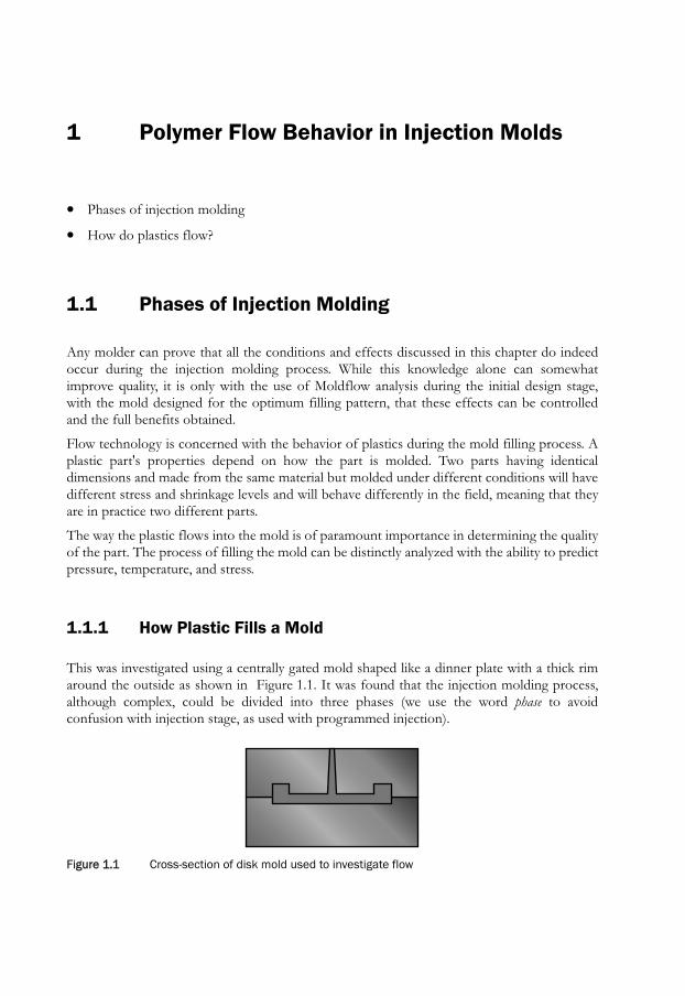
This was investigated using a centrally gated mold shaped like a dinner plate with a thick rimaround the outside as shown in Figure 1.1. It was found that the injection molding process,although complex, could be divided into three phases (we use the word phase to avoidconfusion with injection stage, as used with programmed injection).
Figure 1.gure 1.1 Cross-section of disk mold used to investigate flow

2 Polymer Flow Behavior in Injection Molds
1.1.1.1 Filling Phase
As the ram moves forward, it first moves at a steady speed as the plastic flows into the cavity.This is the filling phase. This phase lasts until the mold is just filled. See Figure 1.2 andFigure 1.3.
1.1.1.2 Pressurization Phase
The pressurization phase begins when the ram moves forward after the filling phase to bringthe mold up to pressure. When the mold is filled, the ram will slow down, but it still movesquite some distance because plastics are very compressible materials. At injection moldingpressure, an extra 15% volume of material can be forced into the cavity. See Figure 1.2 andFigure 1.3.
Although fluids are usually assumed to be incompressible, molten plastics have to beconsidered to be more like a gas. The compressibility of plastics can be observed by blockingoff the nozzle and attempting to purge the barrel. The ram will jump forward when thepressure is applied, but will spring back when the pressure is released.
1.1.1.3 Compensation Phase
After the pressurization phase, the ram still does not stop completely, continuing to creepforward for some time. Plastics have a very large volumetric change of about 25% from themelt to the solid. This can be seen in a short shot; the difference in volume between themolding and the cavity is due to this volumetric change. See Figure 1.2 and Figure 1.3.
The ram moving forward to compensate for the volumetric change in the part is called thecompensation phase. As the volumetric change is 25% and, at the most, only an extra 15% canbe injected in the pressurization phase, there must always be some compensation phase.
Figure 1Figure 1.2 Phases of injection molding
Filling phase
Pressurization phase
Compensation phase
Phases of Injection Molding 3
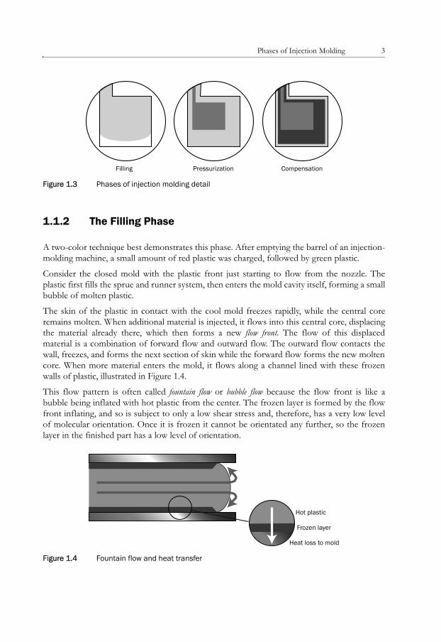
Figure 1.3gure 1.3 Phases of injection molding detail
1.1.2 The Filling Phase
A two-color technique best demonstrates this phase. After emptying the barrel of an injection-molding machine, a small amount of red plastic was charged, followed by green plastic.
Consider the closed mold with the plastic front just starting to flow from the nozzle. Theplastic first fills the sprue and runner system, then enters the mold cavity itself, forming a smallbubble of molten plastic.
The skin of the plastic in contact with the cool mold freezes rapidly, while the central coreremains molten. When additional material is injected, it flows into this central core, displacingthe material already there, which then forms a new flow front. The flow of this displacedmaterial is a combination of forward flow and outward flow. The outward flow contacts thewall, freezes, and forms the next section of skin while the forward flow forms the new moltencore. When more material enters the mold, it flows along a channel lined with these frozenwalls of plastic, illustrated in Figure 1.4.
This flow pattern is often called fountain flow or bubble flow because the flow front is like abubble being inflated with hot plastic from the center. The frozen layer is formed by the flowfront inflating, and so is subject to only a low shear stress and, therefore, has a very low levelof molecular orientation. Once it is frozen it cannot be orientated any further, so the frozenlayer in the finished part has a low level of orientation.
Figure 1.4gure 1.4 Fountain flow and heat transfer
Filling Pressurization Compensation
Hot plastic
Frozen layer
Heat loss to mold
4 Polymer Flow Behavior in Injection Molds
Now, consider what happens upstream. Hot plastic is continuously flowing, bringing new hotmaterial along and generating significant frictional heat. At the same time, heat is being lostthrough the frozen layer to the cold mold surface.
Initially, the frozen layer is very thin, so heat is lost very rapidly. This results in more plasticfreezing and the frozen layer getting thicker, cutting down the heat flow. After a time, thefrozen layer will reach a thickness such that the heat lost by conduction is equal to the heatinput from plastic flow and frictional heating, i.e., an equilibrium condition is reached(Figure 1.4).
It is interesting to do some calculations on the time taken to reach this state of equilibrium.The actual rate of heat flow is very large in comparison with the small heat content of theplastic in the frozen layer. The result is that equilibrium is reached very quickly, often in a timemeasured in a few tenths of a second. As the total filling time is measured in seconds, thefrozen layer reaches an equilibrium state early in the filling cycle.
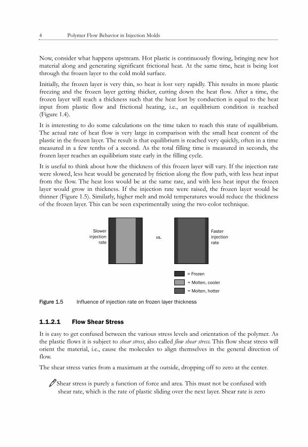
It is useful to think about how the thickness of this frozen layer will vary. If the injection ratewere slowed, less heat would be generated by friction along the flow path, with less heat inputfrom the flow. The heat loss would be at the same rate, and with less heat input the frozenlayer would grow in thickness. If the injection rate were raised, the frozen layer would bethinner (Figure 1.5). Similarly, higher melt and mold temperatures would reduce the thicknessof the frozen layer. This can be seen experimentally using the two-color technique.
Figure 1Figure 1.5 Influence of injection rate on frozen layer thickness
1.1.2.1 Flow Shear Stress
It is easy to get confused between the various stress levels and orientation of the polymer. Asthe plastic flows it is subject to shear stress, also called flow shear stress. This flow shear stress willorient the material, i.e., cause the molecules to align themselves in the general direction offlow.
The shear stress varies from a maximum at the outside, dropping off to zero at the center.
3Shear stress is purely a function of force and area. This must not be confused with shear rate, which is the rate of plastic sliding over the next layer. Shear rate is zero
= Frozen
= Molten, cooler
= Molten, hotter
Slowerinjection
rate
Fasterinjectionrate
vs.

Phases of Injection Molding 5
at the outer edge where the plastic is frozen, rises to a maximum just inwards of the frozen layer, then drops toward the center, as shown in Figure 1.6.
Figure 1.6gure 1.6 Shear rate distribution
If the flow were stopped and the plastic allowed to cool down very slowly, this orientationwould have time to relax, giving a very low level of residual orientation. On the other hand, ifthe material were kept under stress and the plastic snap frozen, most of the orientation wouldbe trapped in the frozen plastic (Figure 1.7).
Figure 1.7gure 1.7 Molecular orientation through the thickness of the part
Min MaxShear rate:
= Tension
= Compression
Molecular orientation trappedin pressurization phase
Gradual reduction of orientationtoward the center of themold as stress levels are lower and the cooling rate is slowerwhich allows more time fororientation to relax
6 Polymer Flow Behavior in Injection Molds
Now consider the orientation from the mold surface toward the center.
The frozen layer itself, formed with very little shear and therefore low orientation, immediatelyfreezes, "setting" the low level of orientation.
The layer of plastic just on the inside of the frozen layer is subject to maximum shear stressand freezes the instant flow stops, trapping almost all the orientation.
This is the orientation pattern: the further toward the center, the more the shear stress dropsand the slower the rate of cooling. This allows more time for the level of orientation to relax,so the residual orientation drops rapidly toward the center. Consider how this pattern willaffect the residual stress level. Oriented material (normally) will shrink more than nonorientedmaterial. On the inner surface of the original frozen layer, highly oriented material wants toshrink a great deal, but it is prevented from doing so by the less-oriented material. The highlyoriented layer ends up being in tension, while the less-oriented material is in compression.
This residual stress pattern is a common cause of part warpage.
3There is a connection�through orientation�between the shear stress during filling (flow stress) and the residual stress in the final molded part. This means shear stress during filling, shown on Moldflow plots, can be used as a design parameter.
1.1.3 The Pressurization Phase
The pressurization phase�from the point of view of flow behavior�is very similar to thefilling phase. The flow rate may drop somewhat as the mold builds up to pressure, resulting inan increase in the thickness of the frozen layer.
The main difference of course, is the increase in hydrostatic (isotropic) pressure. We shall seein chapter 2, section 2.4 Effect of Molding Conditions, that hydrostatic pressure in itself doesnot cause any residual stress.
1.1.4 The Compensation Phase
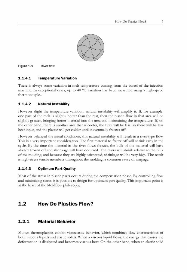
Compensating flow is unstable. Consider the plate molding again (see Figure 1.1). You wouldthink that plastic flowing uniformly through the thin diaphragm would top up the thick rim. Inpractice, the plastic during the compensation phase flows in rivers that spread out like a delta,as illustrated in Figure 1.8. This may seem surprising at first, but it can be explained bytemperature instability.
How Do Plastics Flow? 7
Figure 1.8gure 1.8 River flow
1.1.4.1 Temperature Variation
There is always some variation in melt temperature coming from the barrel of the injectionmachine. In exceptional cases, up to 40 ºC variation has been measured using a high-speedthermocouple..
1.1.4.2 Natural Instability
However slight the temperature variation, natural instability will amplify it. If, for example,one part of the melt is slightly hotter than the rest, then the plastic flow in that area will beslightly greater, bringing hotter material into the area and maintaining the temperature. If, onthe other hand, there is another area that is cooler, the flow will be less, so there will be lessheat input, and the plastic will get colder until it eventually freezes off.
However balanced the initial conditions, this natural instability will result in a river-type flow.This is a very important consideration. The first material to freeze off will shrink early in thecycle. By the time the material in the river flows freezes, the bulk of the material will havealready frozen off and shrinkage will have occurred. The rivers will shrink relative to the bulkof the molding, and because they are highly orientated, shrinkage will be very high. The resultis high-stress tensile members throughout the molding, a common cause of warpage.
1.1.4.3 Optimum Part Quality
Most of the stress in plastic parts occurs during the compensation phase. By controlling flowand minimizing stress, it is possible to design for optimum part quality. This important point isat the heart of the Moldflow philosophy.
1.2 How Do Plastics Flow?
1.2.1 Material Behavior
Molten thermoplastics exhibit viscoelastic behavior, which combines flow characteristics ofboth viscous liquids and elastic solids. When a viscous liquid flows, the energy that causes thedeformation is dissipated and becomes viscous heat. On the other hand, when an elastic solid
8 Polymer Flow Behavior in Injection Molds
is deformed, the driving energy is stored. For example, the flow of water is a typical viscousflow, whereas the deformation of a rubber cube falls into the elastic category.
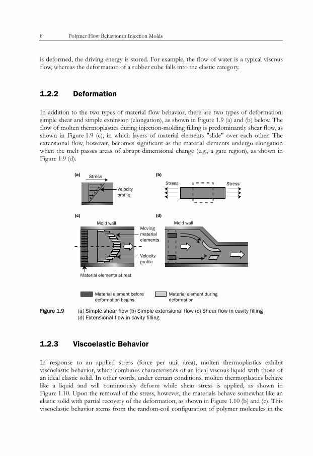
1.2.2 Deformation
In addition to the two types of material flow behavior, there are two types of deformation:simple shear and simple extension (elongation), as shown in Figure 1.9 (a) and (b) below. Theflow of molten thermoplastics during injection-molding filling is predominantly shear flow, asshown in Figure 1.9 (c), in which layers of material elements "slide" over each other. Theextensional flow, however, becomes significant as the material elements undergo elongationwhen the melt passes areas of abrupt dimensional change (e.g., a gate region), as shown inFigure 1.9 (d).
Figure 1Figure 1.9 (a) Simple shear flow (b) Simple extensional flow (c) Shear flow in cavity filling(d) Extensional flow in cavity filling
1.2.3 Viscoelastic Behavior
In response to an applied stress (force per unit area), molten thermoplastics exhibitviscoelastic behavior, which combines characteristics of an ideal viscous liquid with those ofan ideal elastic solid. In other words, under certain conditions, molten thermoplastics behavelike a liquid and will continuously deform while shear stress is applied, as shown inFigure 1.10. Upon the removal of the stress, however, the materials behave somewhat like anelastic solid with partial recovery of the deformation, as shown in Figure 1.10 (b) and (c). Thisviscoelastic behavior stems from the random-coil configuration of polymer molecules in the
StressStress Stress
Mold wall
Material element beforedeformation begins
Material element duringdeformation
Mold wall
Material elements at rest
Movingmaterialelements
Velocity profile
(a) (b)
(c) (d)
Velocityprofile

How Do Plastics Flow? 9
molten state, which allows the movement and slippage of molecular chains under theinfluence of an applied load. However, the entanglement of the polymer molecular chains alsomakes the system behave like an elastic solid upon the application and removal of the externalload. Namely, on removal of the stress, chains will tend to return to the equilibrium random-coil state and thus will be a component of stress recovery. The recovery is not instantaneousbecause of the entanglements still present in the system.
Figure 1.gure 1.10 (a) Ideal viscous liquid deforms continuously under applied stress (b) Ideal elastic solid deforms immediately upon the application of stress, but fully recovers when the stress is removed (c) Molten thermoplastic deforms continuously under the applied stress (like a viscous liquid), but also recovers partially from the deformation uponremoval of the applied stress (like an elastic solid)
1.2.4 Melt Shear Viscosity
1.2.4.1 What Is Shear Viscosity?
Melt shear viscosity is a material's resistance to shear flow. In general, polymer melts are highlyviscous because of their long molecular chain structure. The viscosity of a polymer melt rangesfrom 2 to 3,000 Pa.s (water 10^-1 Pa.s, glass 10^20 Pa.s). Viscosity can be thought of as thethickness of a fluid, or how much it resists flow. Viscosity is expressed as the ratio of shearstress (force per unit area) to the shear rate (rate change of shear strain), as shown inEquation 1.1 and Figure 1.11:
(a) Viscous liquid
(b) Elastic solid
(c) Viscoelastic polymer melt
Initial shape(shear stressto be applied)
Time = Dt Time = 2 x Dt(shear stress to
be removed)
Final deformedshape
d
d
d
d
2d
2d
2d
2d
totalrecovery
partialrecovery