Embed Size (px)
Citation preview
Mono-glass for Providing Distance Informationfor People Losing Sight in One Eye
Masahiro Toyoura∗ Kenji Kashiwagi Atsushi Sugiura Xiaoyang Mao†
University of Yamanashi
Synthesized image
Monitor for healthy eye
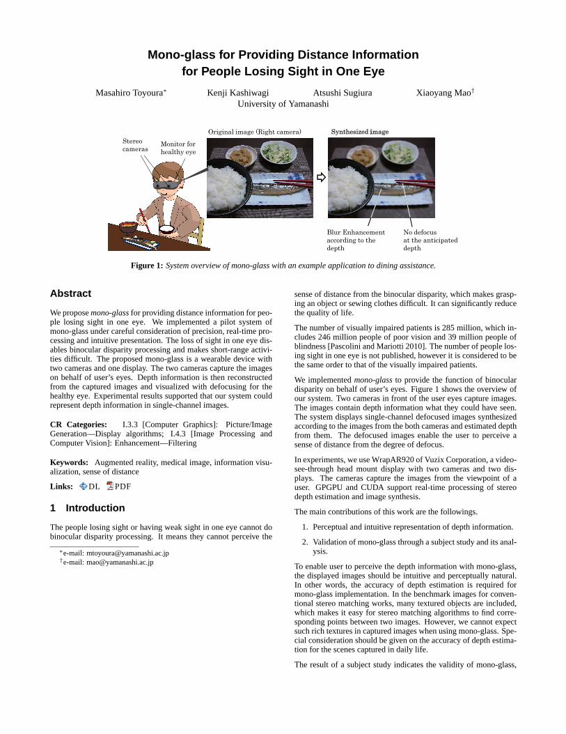
Blur Enhancement according to the depth
Original image (Right camera)
Stereo cameras
No defocus at the anticipateddepth
Figure 1: System overview of mono-glass with an example application to dining assistance.
Abstract
We proposemono-glassfor providing distance information for peo-ple losing sight in one eye. We implemented a pilot system ofmono-glass under careful consideration of precision, real-time pro-cessing and intuitive presentation. The loss of sight in one eye dis-ables binocular disparity processing and makes short-range activi-ties difficult. The proposed mono-glass is a wearable device withtwo cameras and one display. The two cameras capture the imageson behalf of user’s eyes. Depth information is then reconstructedfrom the captured images and visualized with defocusing for thehealthy eye. Experimental results supported that our system couldrepresent depth information in single-channel images.
CR Categories: I.3.3 [Computer Graphics]: Picture/ImageGeneration—Display algorithms; I.4.3 [Image Processing andComputer Vision]: Enhancement—Filtering
Keywords: Augmented reality, medical image, information visu-alization, sense of distance
Links: DL PDF
1 Introduction
The people losing sight or having weak sight in one eye cannot dobinocular disparity processing. It means they cannot perceive the
∗e-mail: [email protected]†e-mail: [email protected]
sense of distance from the binocular disparity, which makes grasp-ing an object or sewing clothes difficult. It can significantly reducethe quality of life.
The number of visually impaired patients is 285 million, which in-cludes 246 million people of poor vision and 39 million people ofblindness [Pascolini and Mariotti 2010]. The number of people los-ing sight in one eye is not published, however it is considered to bethe same order to that of the visually impaired patients.
We implementedmono-glassto provide the function of binoculardisparity on behalf of user’s eyes. Figure1 shows the overview ofour system. Two cameras in front of the user eyes capture images.The images contain depth information what they could have seen.The system displays single-channel defocused images synthesizedaccording to the images from the both cameras and estimated depthfrom them. The defocused images enable the user to perceive asense of distance from the degree of defocus.
In experiments, we use WrapAR920 of Vuzix Corporation, a video-see-through head mount display with two cameras and two dis-plays. The cameras capture the images from the viewpoint of auser. GPGPU and CUDA support real-time processing of stereodepth estimation and image synthesis.
The main contributions of this work are the followings.
1. Perceptual and intuitive representation of depth information.
2. Validation of mono-glass through a subject study and its anal-ysis.
To enable user to perceive the depth information with mono-glass,the displayed images should be intuitive and perceptually natural.In other words, the accuracy of depth estimation is required formono-glass implementation. In the benchmark images for conven-tional stereo matching works, many textured objects are included,which makes it easy for stereo matching algorithms to find corre-sponding points between two images. However, we cannot expectsuch rich textures in captured images when using mono-glass. Spe-cial consideration should be given on the accuracy of depth estima-tion for the scenes captured in daily life.
The result of a subject study indicates the validity of mono-glass,

although there was difference among individuals on how much theyperceive the provided distance. The result also provides a good per-spective for the following works ofcomputational ophthalmology.
2 Related Works
To the best our knowledge, mono-glass is the first device whichcan assist patients losing sight in one eye to perceive distance in-formation. For visually impaired patients, the distance informationhas been provided by virtual white sticks [Okayasu 2009; Okayasu2010]. The sticks provide the depth of obstructions with bumps orvibration on their handles. Our mono-glass, meanwhile, providesthe sense of distance to the users in a way as if it was perceived byboth of their own eyes. In other words, the proposed the systemcan complement the lost sense of distance, which is the best way toenhance the quality of life.
It is well known that defocus provides a cue of distance for human[Vishwanath and Blaser 2010]. A technique has been proposed tosynthesize a defocused image based on estimated depth from a sin-gle image in order to enhance the sense of distance [Okatani andDeguchi 2007; Held et al. 2010]. However, the technique, whichis used for making entertainment movies and so on, has a limita-tion that the structure of captured scene should be quite simple. Itcannot deal with small objects in hand which is required for ourapplication.
Hardware implementation for synthesizing defocus has also beenproposed. Consumer cameras, FinePix F300EXR [FinePix] andPanasonic LUMIX GF2 [LUMIX ], have a function of synthesizingdefocused image by capturing multiple images with different focaldistances. LYTRO light field camera [LYTRO] realizes it by usingcamera lens array. Such cameras cannot provide images with an ar-bitrary degree of defocusing, because they do not reconstruct depthinformation, but synthsize pixel-level composite images from realcaptured images. We adopted software implementation for mono-glass for this reason.
The depth map is calculated as the disparity of stereo cameras inour method. The method proposed by Wanget al. [Wang et al.2006] provides a good result by referring corresponding points andtheir neighborhoods in stereo paired images. GPU implementationcan accelerate the speed of the method. Since calculating depthmaps is a fundamental problem of computer vision, new even bettermethods have been proposed in recent years [Gong et al. 2007].Whereas Wanget al. adopted DP matching for calculating the depthmap, DP with 4 states [Criminisi et al. 2007] and belief propagation[Yang et al. 2010] could improve the results. Other than stereocameras, pattern code projection [Kinect], combined with stereocameras [Yang et al. 2007] and coded aperture [Zhou et al. 2009]may provide better solution to our application in near future. For themeantime, however, we adopt the recent fundamental method byWanget al., by which depth map estimation with two small camerasonly can balance the precision, speed, and physical size well.
An implementation on IC tips, such as in Kinect, can reduce thecomputation cost. But we choose software implementation for as-suring the flexibility of personal adaptation of defocusing parame-ters. More suitable devices rather than stereo cameras might appearin near future but at this moment, a personal 3D range scanner likeKinect is still too large to wear on the head. We employed stereomatching for estimating the depth, and GPGPU for acceleration ofthe computation.
3 Artificial Defocused Image Synthesis
Using estimated depth map, we synthesize single-channel imagesrepresenting depth information. By defocusing images accordingto the estimated depth, a user can perceive the distance from thesingle-channel images.
Figure2 shows the concept of how to change the degree of defo-cusing. The defocusing is controlled by blur radiusσ. The solidline represents the original defocus of a real camera.σ is definedby the focal lengthz0 and the estimated distance from lensz withconstant coefficientA as
σ = A|z − z0|
z0. (1)
Two dotted lines represent the defocus controlled by parametersα,β, γ andδ as the following:
σ′ = α
(γ|z − z0|
z0+ δ
)β
. (2)
Distance from lens z
Blu
r ra
diu
s σ
Focal length z0
0
Figure 2: Blur radius with defocus controlling parameters.
Note thatδ is a small positive number for assuringσ′′ to be posi-tive. In addition, we introduce a parameterϕ for representing non-defocusing range.
σ′′ = α
(γmax(0, |z − z0| − ϕ)
z0+ δ
)β
. (3)
The pixel valueIσ′′(x, y) in the defocused image is calculated withthe pixel valueI(x, y) in the original image and the blur radiusσ′′
is given in the following way:
Iσ′′(x, y) =∑(x′,y′)∈Ω(x,y)
I(x, y)exp(−g(x, y, x′, y′)2/σ′′2)
∑(x′,y′)∈Ω(x,y)
exp(−g(x, y, x′, y′)2/σ′′2), (4)
where Ω(x, y) is a set of neighbors of the pixel(x, y) andg(x, y, x′, y′) the Euclid distance between(x, y) and(x′, y′).

According to Eq. (3), even when an object is positioned at onlya very small distance from the focal lengthz0, the object can beobserved as largely defocused. The degree of defocus is controlledwith α, β andγ non-linearly. This can only be realized by softwareimplementation using depth estimation.
4 Experiments
In experiments, we used WrapAR920 of Vuzix Corporation. It hastwo independent display monitors and stereo cameras at the posi-tion of user’s eyes. Captured images from the stereo cameras aretransferred to a PC. Depth maps are generated and defocus is en-hanced according to the depth maps. Defocused images are dis-played on the monitor for the healthy eye. Our system was im-plemented with Visual Studio 2010, CUDA4.2 and OpenCV2.4.1,and executed on a desktop PC (OS: Windows7 64bit, CPU: IntelCore2Quad 2.83GHz, GPU: NVidia GeForce GTX 460 1GB, MM:2GB).
The length of the baseline of stereo cameras was60mm. The phys-ical focal length of each camera was set to400mm. An initial z0is also set to400mm, and we allow the subjects to changez0 asthey like. Parameters in Eq. (3) were empirically set asα = 3.0,β = 0.5, γ = 5.0, ϕ = 20.0 andδ = 0.001.
4.1 Defocused Image Synthesis
Figure4 shows examples of synthesized images. The original im-ages as shown in Figure4(a) do not have noticeable defocus. Theimages as shown in Figure4(b) are synthesized with the originalimages and their corresponding depth maps. The images except forthe rightmost image include not defocused regions, which indicatethat the regions are positioned at the anticipated distance. In therightmost image, almost all regions with rich texture are defocused.It means there are no regions with rich texture at the anticipateddistance.
It took 46.75ms on average for capturing and synthesizing a singleimage and frame rate was21.93fps. We can regard the process-ing time as real-time. We used the resolution of80 × 60 whengenerating depth maps for achieving real-time processing and forsuppressing artifacts.
4.2 Subject Study
The synthesized images were provided to right eyes of 8 subjectsdenoted by A to H (5 male and 3 female in their 20s or 30s withboth eyes being healthy) with mono-glass. The dominant eye ofC is left, and those of the others are right. Corrected visions werebetween 0.6 and 1.2. No images were displayed to the left eyes.
The experimental environment is shown in Figure3. The subjectsare asked to perform the task of inserting a cylinder of20mm indiameter and85mm in length into two holes on a box placed on atable. The diameters of the holes are25mm.
The subjects repeat the following steps 30 times.
1. Put the cylinder on the front of the box.
2. Insert the cylinder into the right hole.
3. Look ahead.
4. Put the cylinder on the front of the box.
5. Insert the cylinder into the left hole.
6. Look ahead.
80cm
50cm
40cm
40cm
10cm
70cm
50cm
15cm
35cm
30cm
10cm
20mm25mm
Figure 3: Environment for subject study.
The task requires the perception of distance. The information ofdistance is reset by step 3 and 6. We instructed the subjects that thetask can be easily done by setting both of the cylinder and the holesat a matching distance which is indicated by without being defo-cused. We had the subjects grasp the top side of the cylinder. Thecylinder was wrapped with rich texture and printed papers with par-allel rules were also put on the box so that the subjects can perceivethe defocus effect. We believe that it is reasonable in real applica-tion to assume that handling tools have rich-texture. In the exampleof Figure1, the user is forced to use chopsticks with rich-texture.
Subjects A to D did the task in an order of synthesized, original,synthesized, and original images. Subjects E to H did the task in anorder of original, synthesized, original, and synthesized images.
The results are shown in Figure5. We adopt t-test for examiningthe difference of time for completing the second task. The secondtime of subjects C, D, E, G and H, and the first time of A, C, D, G,and H became significantly shorter in the case that the synthesizedimages were displayed. Only the first time of subject F signifi-cantly became longer in the case that the synthesized images weredisplayed. There are also differences among individuals even in thesecond study.
To summarize the subject study, our synthesized images could pro-vide distance information for some subjects, while there were dif-ferences among individuals.
5 Discussion and Future Work
We proposed mono-glass to provide distance information for los-ing sight in one eye. The distance information is represented bydefocusing. The result of the subject study supported the validityof mono-glass even though there was difference among individuals.
As an important future work, we will continue to improve the real-time depth estimation. The time required for synthesizing defo-cused images of resolution80 × 60 in GPGPU with CUDA is21.39fps. Finer resolution with larger window size could give usmore accurate result. Since the system requires a laptop computerat least, currently it is not easy to wear the system. However, weexpect GPU computing will be realized in mobile environments innear future.
Optimization of parameters for defocusing is an important futurework. We will try to explorer the parameters in addition to makingintuitive interfaces for controlling them.
References
CRIMINISI , A., BLAKE , A., ROTHER, C., SHOTTON, J., ANDTORR, P. 2007. Efficient dense stereo with occlusions for new

(a) Original images captured by the right camera.
(b) Synthesized defocused images according to estimated distance maps.
Figure 4: Results of defocused image synthesis according to estimated distance.
0
2000
4000
6000
A B C D E F G H
Original (1st) Synthesized (1st) Original (2nd) Synthesized (2nd)
**
**** **
** ** **
+ *
(msec) ** **
Figure 5: Difference of execution time between original and synthesized images. Subjects A, B, C and D executed the task with originalimages first, and E, F, G and H did with synthesized images first. Average execution time of the task with a textured stick. The leftmost barsindicate the execution time in the case of original images, the second bars from the left are synthesized images, the third bars from the left arefor original images of the second time, and the rightmost bars are for synthesized images of the second time. The results were analyzed witht-test.+: p < 0.10, ∗: p < 0.05, and∗∗: p < 0.01. The directions of arrows indicate the smaller elements.
view-synthesis by four-state dynamic programming.Interna-tional Journal of Computer Vision 71, 1, 89–110.
FujiFilm, FinePix F300EXR. http://www.fujifilm.co.jp/corporate/news/articleffnr0414.html.
GONG, M., YANG, R., WANG, L., AND GONG, M. 2007. Aperformance study on different cost aggregation approaches usedin real-time stereo matching.International Journal of ComputerVision (IJCV) 75, 2, 283–296.
HELD, R. T., COOPER, E. A., O’BRIEN, J. F., AND BANKS,M. S. 2010. Using blur to affect perceived distance and size.ACM Transactions on Graphics 29, 2, 1–16.
Microsoft Corporation, Kinect for Xbox 360. http://www.xbox.com/kinect/.
Panasonic, LUMIX GF2. http://panasonic.jp/dc/gf2/.
LYTRO, Light Field camera. https://www.lytro.com/camera.
OKATANI , T., AND DEGUCHI, K. 2007. Estimating scale of ascene from a single image based on defocus blur and scene ge-ometry. In IEEE Conference on Computer Vision and PatternRecognition (CVPR).
OKAYASU , M. 2009. The development of a visual system for thedetection of obstructions for visually impaired people.Journalof Mechanical Science and Technology 23, 10, 2776–2779.
OKAYASU , M. 2010. Newly developed walking apparatus for iden-tification of obstructions by visually impaired people.Journal ofMechanical Science and Technology 24, 6, 1261–1264.
PASCOLINI, D., AND MARIOTTI , S. P. 2010. Global estimates ofvisual impairment. Tech. rep., BJO Online First.
V ISHWANATH , D., AND BLASER, E. 2010. Retinal blur and theperception of egocentric distance.Journal of Vision 10, 10, 1–16.
WANG, L., L IAO , M., GONG, M., YANG, R., AND NISTER, D.2006. High-quality real-time stereo using adaptive cost aggrega-tion. In International Symposium on 3D Data Processing, Visu-alization and Transmission (3DPVT).
YANG, Q., YANG, R., DAVIS , J.,AND NISTER, D. 2007. Spatial-depth super resolution for range images. InIEEE Conference onComputer Vision and Pattern Recognition (CVPR), 1–8.
YANG, Q., WANG, L., AND AHUJA, N. 2010. A constant-spacebelief propagation algorithm for stereo matching. InIEEE Con-ference on Computer Vision and Pattern Recognition (CVPR),1458–1465.
ZHOU, C., LIN , S., AND NAYAR , S. 2009. Coded aperture pairsfor depth from defocus. InComputer Vision, 2009 IEEE 12thInternational Conference on, 325–332.