Embed Size (px)
Citation preview
*
3’-0"
Monotube Arm
* The Contractor shall verify that the drilled shaft
locations shown on the Signalization Plans are within
the R.O.W. Shaft locations may be adjusted as
required and as approved by the Engineer. ELEVATION VIEW
(Not to Scale)
-> ASTM A153 Class C or D
depending on size
-> ASTM A123
’PA’/3 3/64 3’ ’PA’/3 3/64 6’
���� ����
Damping Device
(see Note No. 15 and Std. Index 17749)
Note: For referenced dimensions see
Index 17746 Sheet 4 of 4.
NOTE: Contractor shall verify these Dimensions
Prior to Fabrication of Pole.
’PB’ Spaces
MONOTUBE SIGNAL STRUCTURE NOTES
CAMBER DETAILS
Note: Fabricate with rolling camber up.
’PC’’PC’
’PC’
185’ Span
’PC’’PC’
’PC’
160’ Span
135’ Span
’PC’’PC’ ’PC’
110’ Span
’PC’
’PC’ ’PC’
3’-0"
Span Length = ’PA’
’PA’/3 3/64 3’
| Pole
See Detail ’A’
(Sheet 4 of 4)
| Monotube Arm
Standard Design
Financial Project ID
Span Length
Manufacturer’s Name
Certification No.
Special Design
Financial Project ID
Pole Diameter (in.)
Pole Wall Thickness (in.)
Arm Diameter (in.)
Arm Wall Thickness (in.)
Manufacturer’s Name
Base Plate Connection
and Handhole Top of
Grout Pad
Top of
Finished Grade
Provide 1/2 " Weep Hole located at
bottom of Monotube 8" from
flange connection
(Typ. all Arm Sections)
* 1
9’-0" t
o 2
3’-0"
Drilled Shaft
Aluminum Identification Tag Not to Exceed 2" x 4". Secure
to Shaft by 0.125" Stainless Steel rivets or screws. Fabricators
to provide details for approval. Identification Tag Located on
inside of Pole visible from handhole, or on outside of pole
inside terminal compartment. Tag to be stamped with the
following information :
~~
-> API-5L-X42 (42 ksi yield)
or ASTM A618 Grade
-> ASTM A709 Grade 36
-> ASTM A1011, Grade 50, 55, 60, or 65 ksi
-> ASTM A709 Grade 50
-> E70XX
-> ASTM A325 Type 1
-> ASTM F1554 Grade 55 ksi
-> ASTM A563 Grade A Heavy Hex
-> ASTM F436 Type 1
-> AISI Type 316
-> ASTM B26 (319-F)
1) Signal Structure Materials shall be as follows:
Poles & Monotube Arm
Handhole Frame
Handhole Cover
Steel Plates
Weld Metal
Bolts (except Anchor Bolts)
Anchor Bolts
Nuts for Anchor Bolts
Washers for Anchor Bolts
Stainless Steel Screws
Aluminum Nut Cover
2) Reinforcing Steel shall be ASTM A615, Grade 60 ksi.
3) Concrete shall be Class ?! (Drilled Shaft) with a minimum 28-day compressive
strength of 4,000 psi for all environmental classifications.
4) Grout shall have a minimum 28-day compressive strength of 5,000 psi and shall meet
the requirements of Section 934 of the Specifications. Grout at the base of
uprights shall be installed a minimum of 7 days prior to the installation
of signals or sign panels. The standoff distance (the distance between the bottom of
the leveling nut and the top of the foundation) shall not exceed one anchor bolt diameter.
5) All welding shall conform to American Welding Society Structural Welding Code (Steel)
ANSI/AWS D1.1 (current edition).
6) All Steel items shall be galvanized as follows:
All Nuts, Bolts and Washers
All other steel items
(including Pole & Monotube Arm)
7) The Design Wind Speed is 110mph with a 30 percent gust factor.
8) Alternate Designs for this Structure are not allowed.
9) Except for Anchor Bolts, all bolt hole diameters shall be equal to the bolt diameter
plus 1/16 " , prior to galvanizing. Hole diameters for Anchor Bolts shall not exceed
the bolt diameter plus 1/2 ".
10) Sign Panels and Signals attached to the Monotube shall be located as shown on
the Traffic Signal Plans. Wire access holes shall not exceed 1 1/2 " in diameter.
11) The Pole shall be installed vertically. Arm Camber shall be accounted for in the
Flange Connections.
12) Locate handhole 180^ from monotube arm.
13) All signals shall be installed vertically.
14) Monotube Arm & Poles shall be fabricated from round pipe.
15) If damping devices are required by the Engineer, they shall be installed within
3’-0" 3/64 of the third points of the Span Length.
16) Each Standard Monotube Signal Structure has been designed for two free
swinging internally illuminated street signs, per pole, which are acceptable by
Contractor Certification provided they meet the applicable requirements of
Specification Section 699, weigh no more than 75 lbs. (each) and are no
more than 12 sq. ft in area (each).
17. Manufacturers seeking approval of a monotube assembly for inclusion
on the Qualified Products List must submit a QPL Product Evaluation Application
along with design documentation and drawings showing the product meets all
specified requirements of this Index.
18. If a grout pad is not installed, baseplates shall be secured with double nuts both
above and below the baseplate. The locking nuts shall be half-height nuts. The
standoff distance (the distance between the bottom of the full-height leveling nut
and the top of the foundation) shall not exceed one anchor bolt diameter. In rural
areas, the top of the foundation should be greater than 12" above finished grade.
A vertically placed wire cloth screen between the baseplate and the top of the
foundation shall be wrapped horizontally around the baseplate with a 3" min. lap.
The wire cloth shall be galvanized steel standard grade plain weave 2x2 mesh
0.063" dia. wire. The screen shall be attached to the baseplate with stainless
steel self-tapping 1/4 " screws with stainless steel washers spaced at 9" centers.
Sheet No.
Index No.
2006 FDOT Design StandardsRevision
17746
07/01/05
MONOTUBE SIGNAL STRUCTURE
1 of 4
Last
���
���

2’-0" 2’-0"14’-6"14’-6"
3’-0"3’-0"
DESIGN LOADING TREE FOR MONOTUBE SPAN SIGNAL STRUCTURE
Note: Signal Backplates on 4 of the 8 signals are included in the design of Standard Arms.
PLAN VIEW - MONOTUBE DESIGN INTERSECTION
5’ Utility Strip (Typ.)
5’ Sidewalk (Typ.)
3 ~
12
’ L
an
es
(Ty
p.)
2 ~
12
’ L
an
es
(Ty
p.)
6’ Traffic
Separator (Typ.)
5’ Bike Lane (Typ.)
5-Section
Signals
5-Section
Signals
3-Section
Signals
3-Section
Signals
’A’’B’
12 sq. ft. (max) internally illuminated
sign on a hinged bracket attached to pole
(2 per pole)
12 sq. ft. (max.) internally illuminated
sign on a hinged bracket attached to pole
(2 per pole)
’A’
Span Length
INSTRUCTIONAL NOTES:
Classification = Cohesionless (Fine Sand)
Friction Angle = 30 Degrees (30^)
Unit Weight = 50 lbs./cu. ft. (assumed saturated)
Only in cases where the Designer considers the soil types of the specific site location
to be of lesser strength properties should an analysis be required. Auger borings,
SPT borings or CPT soundings may be utilitzed as needed to verify the assumed soil
properties, and at relatively uniform sites, a single boring or sounding may cover
several foundations. Furthermore, borings in the area that were performed for other
purposes may be used to confirm the assumed soil properties.
Note:
The signal configuration shown represents the maximum allowable span
for which this monotube standard is applicable (185’-0"). It allows for the
following components:
a. 5 ~ 12’ traffic lanes (2 thru lanes in each direction + 1 turn lane)
b. 1 ~ 6’ traffic separator
c. 1 ~ 5’ bike lane per direction of traffic
d. 1 ~ 5’ utility strip per direction of traffic
e. 1 ~ 5’ sidewalk per direction of traffic
The minimum monotube design span (110’-0") allows only for 5 ~ 12’
traffic lanes (item "a" above). It is assumed that for this case there
are no traffic separators,bike lanes, utility strips or sidewalks.
Note: For referenced dimensions see Index 17746 Sheet 4 of 4.
| of Arm
Top of
Finished
Grade
Arm
Heig
ht
19
’-0
" t
o 2
3’-0
"
1. This index, 17746, is for use in preparing signalization plans when monotube
assemblies are required. This standard establishes the requirements of monotube
components listed on on the Qualified Products List (QPL). When using components
on the QPL, the span length and heights of each pole will be the only information
required in the Contract Plans, and Shop Drawings are not required.
2. If a monotube configuration does not meet the requirements stated below, a special
design and shop drawing submittal is required.
3. Four standard monotube configurations are provided. The standard arm length
and the signal locations used for design of the arm are shown on the monotube
design loading tree on this sheet. If the same arrangement of signals is used with
one or more signals closer to the nearest pole, the standard monotube may be used.
If the same arrangement is used but one or more signals are further from the nearest
pole, or if a different configuration of signals is used, a special design is required.
If any signs are to be attached to the monotube arm, a special design is required.
4. Standard monotube span lengths of 110’-0", 135’-0", 160’-0" and 185’-0" are shown.
For other required span lengths with the same configuration of signals in the
same loations or closer to the poles, the standard monotube design with the next
largest standard span length may be used. The difference in length shall be
removed from the center horizontal segment(s) of the span. If a span longer than
185’-0" is to be used, a special design is required.
5. The standard monotube is valid for an arm heights between 19’ and 23’, inclusive.
A special design is required for all heights greater than 23’. If an arm height of less
than 19’ is to be utilized with the same configuration of signals in the same locations
or closer to the poles, the standard monotube may be used, provided that minimum
required clearances to the roadway are maintained.
6. The foundations for the standard monotube are pre-designed and are based upon
the following conservative soil criteria which covers the great majority of soil types
found in Florida:
| Pole
| Pole
Sheet No.
Index No.
2006 FDOT Design StandardsRevision
17746
02
MONOTUBE SIGNAL STRUCTURE
2 of 4
Last
���
���
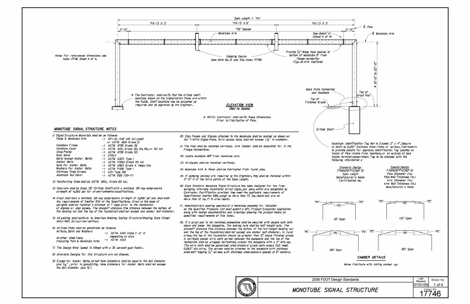
SECTION A-A
| Drilled Shaft
FOUNDATION PLAN
A A
C
SECTION C-C
Note: Concrete and Reinforcement not shown.
B B
BASE PLATE AND ANCHORAGE ELEVATION
2’-2"
Lap
(M
in.)
| Monotube Arm
and Handholes
Align Anchor Bolt with
| Monotube Arm
Drilled Shaft
Double Nuts (Typ.)
C
Drilled Shaft
45^2"
Min
.
3/4
"
1/4 " Plate Washer
Double Nuts, Top Nut
may be 1/2 height ’Jam’ Nut
(Cast Aluminum Nut
Cover not shown)
2"
Min.
Leveling Nut
Grout Pad
SECTION B-B
4 1/
2 "
Center of
Drilled Shaft
Top of Grade
or Sidewalk
Edge of
Base Plate
5/8 " X 5/8 " Chamfer
6"
#5 Tie Bars
@ 1’-6"
6" C
over
#5
Tie
Bars @
1’-6
"6" C
over
6" Cover
1’-
8"
Note: 6" min. cover on Shaft Reinforcement
8"
’FH’
’FH’
’FJ’
’FK’ ~ #10 Bars
Equally Spaced
’FH’
’FA’
’FH’-’FA’
2
’FH’-’FA’
2
’FA’
’FB’
’FC
’
Center of Handhole
(See Handhole Details)
Center of Drilled Shaft,
Base Plate, and Pole
*
3/4 " Dia. Weep Hole
One per Pole
placed between Bolts or
3/8 " \ all-cotton sash
cord wick attached to
exterior of pole, extended
beyond grout pad and
installed prior to grouting
Note: For referenced dimensions see Index 17746 Sheet 4 of 4.
’FK’ ~ #10 Bars
Equally Spaced
* Anchor Bolt Group locations may be 3/64 1/2 " in the direction of the span
’FL
’
| ’FE’ Dia. Anchor Bolt
Threaded 8" min.
top and bottom
’FA’-’FB’
2
’FG’
’FF’
’FD’ ~ ’FE’ Dia. Anchor Bolts
Equally Spaced with
Aluminum Nut Covers
11 ga. Terminal Compartment
cover. Bolt to frame with
4-1/4" stainless steel
screws.
1/4 " thick Terminal Compartment frame
(Height 2’-0" Min. - 2’-6" Max.)
7" Min. - 8 1/2 " Max.
Sheet No.
Index No.
2006 FDOT Design StandardsRevision
17746
02
MONOTUBE SIGNAL STRUCTURE
3 of 4
Last
���
���
A
A
A
A
B
B
Bolted Flange Splice
2"
SECTION A-A
SECTION B-B
CJP
DETAIL ’A’
| Pipe
C
C
SECTION C-C
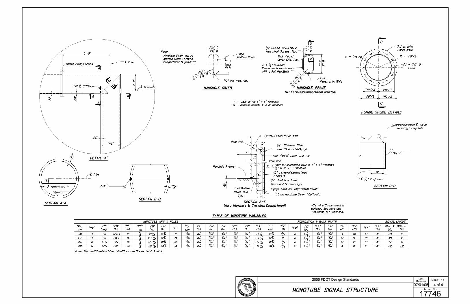
FLANGE SPLICE DETAILS
HANDHOLE FRAMEHANDHOLE COVER
X
X
11 Gage
Handhole Cover
Full
Penetration Weld
Tack Welded
Cover Clip, Typ.
1’-
2"
4" x 3/8 " Handhole
Frame made continuous
with a Full Pen. Weld
1/4 " Dia. Stainless Steel
Hex Head Screws, Typ.
5/16 " mm Hole,Typ.
R = ’PE’/2 R = ’PG’/2
’PG’/2
Symmetrical about | Splice
except 1/2 " weep hole
8"
| 1/2 " Weep Hole
’PH’/2
’PE’
’PG’/2
’PH’/2
’PJ’ ~ ’PK’ \
Bolts
3’-0"
| Pole
| Handhole
’PA’
(ft)’PB’
’PC’
(deg)
’PE’
(in)
’PG’
(in)
’PH’
(in)
’FA’
(in)
’FB’
(in)
’FC’
(in)
’FF’
(in)
FOUNDATION & BASE PLATE
TABLE OF MONOTUBE VARIABLES
Dim. ’A’
(ft)
Dim. ’B’
(ft)
SIGNAL LAYOUTMONOTUBE ARM & POLES
110
135
160
185
4
4
5
6
1.5
1.5
1.25
1.75
14
16
18
22
3/8
3/8
3/8
3/8
21 1/2
23 1/2
25 1/2
29 1/2
17 3/4
19 3/4
21 3/4
25 3/4
21 1/2
23 1/2
25 1/2
29 1/2
17 3/4
19 3/4
21 3/4
25 3/4
1 7/8
2
2 1/8
2 1/4
’FD’
8
8
8
10
’FE’
(in)
29
40
51
62
13
16
19
22
’PD’
(in)
1.093
1.031
1.156
1.125
’PD’
’PD
’
’PD’
Note: For additional variable definitions see Sheets 1 and 3 of 4.
T - denotes top 3" x 5" handhole
B - denotes bottom 4" x 8" handhole
3 3/4 " T
4 3/4 " B
5 3
/4 "
T
8 3
/4 "
B
R = 1 7/8 " T
R = 2 3/8 " B
5" T
8" B
3" T
4" B
R =
1 1
/2 " T
R =
2 B
’P
D’
8
10
12
14
’PJ’’PF’
(in)
’PK’
(in)
’PL’
(in)
’PM’
(in)
’PN’
(in)
’PO’
(in)
’PP’
(in)
1 1/4
1 1/4
1 1/4
1 1/4
2 1/4
2 1/4
2 1/4
2 1/4
5/16 "
5/16 "
5/16 "
5/16 "
5/16 "
5/16 "
5/16 "
5/16 "
1/4 "
1/4 "
1/4 "
1/4 "
3/16 "
3/16 "
3/16 "
3/16 "
3
3.5
3.5
4
’FH’
(ft)
1 1/2 "
1 1/2 "
1 1/2 "
1 1/2 "
’FJ’
(ft)
12
13
14
16
5/16 "
5/16 "
5/16 "
5/16 "
10
12
12
16
’FK’’FG’
(in)
5/16 "
5/16 "
5/16 "
5/16 "
’FL’
(in)
45
45
45
45
’PF
’
’PO’ 1/64 Stiffener
’PP’
’PM’
’PN’
’PL’ circular
flange plate
’PO’ 1/64 Stiffener
Handhole Cover may be
omitted when Terminal
Compartment is provided.
Note:
*Terminal Compartment is
optional. See Monotube
Tabulation for locations.
(w/Terminal Compartment omitted)
1"
Handhole Frame
Tack Welded Cover Clip Typ.
4"
1/4 " Stainless Steel Hex Head Screws, Typ.
3/8
"
Pole Wall
1"
SECTION E-E
(thru Handhole & Terminal Compartment)
1/4 " Terminal Compartment
Frame *
11 gage Terminal Compartment Cover
1/4 "
Pole Wall
Tack Welded Cover Clip Typ.
3/8 " @ 3" x 5" Handhole
1/4 " Stainless Steel Hex Head Screws, Typ.
11 Gage Handhole Cover ( Optional )
Partial Penetration Weld
Partial Penetration Weld @ 4" x 8" Handhole
Sheet No.
Index No.
2006 FDOT Design StandardsRevision
17746
07/01/05
MONOTUBE SIGNAL STRUCTURE
4 of 4
Last
���
���
![Steel Plate for Bridges - Evraz A709/A709M Grade AASHTO M270M/ M270 Grade SI [U.S.] Other Specifications Yield Strength Minimum, ksi [MPA] Plate Dimensions* Thickness inches Width](https://img.pdfslide.net/doc/110x75/5ae88fb47f8b9aee078fac1d/steel-plate-for-bridges-a709a709m-grade-aashto-m270m-m270-grade-si-us-other.jpg)