Embed Size (px)
Citation preview

MONTANA RESOURCES, LLP
YANKEE DOODLE TAILINGS IMPOUNDMENT
PREPARED FOR:
Montana Resources, LLP
600 Shields Avenue
Butte, Montana
59701
VA101-126/12-5
Rev 3
May 1, 2018
CONSTRUCTION MANAGEMENT PLAN
Knight Piésold www.knightpieso ld .com
C O N S U L T I N G
PREPARED BY:
Knight Piésold Ltd.
Suite 1400 – 750 West Pender Street
Vancouver, BC V6C 2T8 Canada
p. +1.604.685.0543 • f. +1.604.685.0147

Knight Piésold Ltd. Suite 1400 750 West Pender Street Vancouver, British Columbia Canada V6C 2T8 Telephone: (604) 685-0543 Facsimile: (604) 685-0147 www.knightpiesold.com
MONTANA RESOURCES, LLP YANKEE DOODLE TAILINGS IMPOUNDMENT
CONSTRUCTION MANAGEMENT PLAN VA101-126/12-5
Rev Description Date
0 Issued in Final December 20, 2016
1 Issued with Marked Revisions February 27, 2017
2 Issued with Marked Revisions July 21, 2017
3 Issued with Marked Revisions May 1, 2018

MONTANA RESOURCES, LLP
YANKEE DOODLE TAILINGS IMPOUNDMENT
CONSTRUCTION MANAGEMENT PLAN i of vi VA101-126/12-5 Rev 3May 1, 2018
TABLE OF CONTENTS
PAGE
TABLE OF CONTENTS ......................................................................................................................... i
1 – INTRODUCTION ............................................................................................................................. 1 1.1 SCOPE AND OBJECTIVES ................................................................................................. 1 1.2 COORDINATE SYSTEM ...................................................................................................... 1 1.3 ROLES AND RESPONSIBILITIES ....................................................................................... 2
General .................................................................................................................... 2 Montana Resources, LLP ........................................................................................ 2 Regulatory Environment .......................................................................................... 2 Engineer of Record .................................................................................................. 2 Independent Review Panel ...................................................................................... 3
1.4 DEFINITIONS ....................................................................................................................... 3 1.5 DESIGN DESCRIPTION ....................................................................................................... 3
General .................................................................................................................... 3 West Embankment Drain ......................................................................................... 4 Fill Material Zones .................................................................................................... 5 Extraction Basin and Drain Pod Pump-Back Systems ............................................ 6 Geotechnical Instrumentation .................................................................................. 6
2 – QUALITY MANAGEMENT .............................................................................................................. 7 2.1 QUALITY CONTROL ............................................................................................................ 7 2.2 QUALITY ASSURANCE ....................................................................................................... 7 2.3 DOCUMENTATION .............................................................................................................. 8
Design Documentation ............................................................................................. 8 Quality Documentation ............................................................................................. 8 Summary of Reporting Responsibilities ................................................................... 9 Documentation Submittals ..................................................................................... 10
3 – EARTHWORKS ............................................................................................................................. 11 3.1 SUBGRADE PREPARATION ............................................................................................. 11
Clearing, Stripping and Grubbing .......................................................................... 11 Topsoil Stockpiling ................................................................................................. 11 Subgrade Preparation – Footprint for Zone U ....................................................... 11 Subgrade Preparation – Footprint for Zone D1 & West Embankment Drain ......... 11 Sloping Subgrade .................................................................................................. 11 Bedrock Subgrade ................................................................................................. 11 Subgrade Preparation for Geotextiles ................................................................... 12
3.2 EXCAVATION ..................................................................................................................... 12 Stability and Protection of Temporary Excavations ............................................... 12
3.3 FILL PLACEMENT .............................................................................................................. 12 Mine Development Material Sources ..................................................................... 12
▲R3

MONTANA RESOURCES, LLP
YANKEE DOODLE TAILINGS IMPOUNDMENT
CONSTRUCTION MANAGEMENT PLAN ii of vi VA101-126/12-5 Rev 3May 1, 2018
External Borrow Sources ....................................................................................... 12 Gradation Specifications ........................................................................................ 12 Acid Generating Potential ...................................................................................... 13 Durability ................................................................................................................ 13 Fill Placement and Compaction ............................................................................. 13 Fill Placement during Freezing Conditions ............................................................ 15 Fill Material Quality Control Testing ....................................................................... 16 Protection and Maintenance .................................................................................. 18 Survey .................................................................................................................... 18
3.4 CONSTRUCTION TOLERANCES ...................................................................................... 19 3.5 CONSTRUCTION DEWATERING ...................................................................................... 19 3.6 EARTHWORKS INSPECTION AND TEST PLAN .............................................................. 20
4 – GEOTEXTILE ................................................................................................................................ 22 4.1 SCOPE OF WORK ............................................................................................................. 22 4.2 SUBMITTALS ...................................................................................................................... 22 4.3 DELIVERY, HANDLING AND STORAGE OF GEOTEXTILES .......................................... 22 4.4 GEOTEXTILE SPECIFICATION ......................................................................................... 22 4.5 INSTALLATION PROCEDURES ........................................................................................ 23 4.6 GEOTEXTILE INSPECTION AND TEST PLAN ................................................................. 24
5 – GEOMEMBRANE LINERS ........................................................................................................... 25 5.1 SCOPE OF WORK ............................................................................................................. 25 5.2 SUBMITTALS ...................................................................................................................... 25 5.3 GEOMEMBRANE QUALIFICATIONS ................................................................................ 25 5.4 DELIVERY, HANDLING AND STORAGE OF GEOMEMBRANE ...................................... 25 5.5 GEOMEMBRANE SPECIFICATION................................................................................... 25 5.6 INSTALLATION PROCEDURES ........................................................................................ 26
Geomembrane Placement and Seam Welding ..................................................... 26 5.7 GEOMEMBRANE INSPECTION AND TEST PLAN ........................................................... 27
Strength Testing ..................................................................................................... 28 5.8 GEOMEMBRANE REPAIR PROCEDURE ......................................................................... 31
6 – CONCRETE .................................................................................................................................. 32 6.1 SCOPE OF WORK ............................................................................................................. 32 6.2 CONCRETE FORMWORK AND FALSEWORK ................................................................. 32 6.3 CONCRETE STEEL REINFORCEMENT ........................................................................... 32 6.4 CAST-IN-PLACE CONCRETE ........................................................................................... 33 6.5 CONCRETE INSPECTION AND TEST PLAN ................................................................... 36
7 – PIPEWORKS AND APPURTENANCES ....................................................................................... 38 7.1 SCOPE OF WORK ............................................................................................................. 38 7.2 APPLICABLE SPECIFICATIONS AND REGULATIONS ................................................... 38 7.3 SUBMITTALS ...................................................................................................................... 38 7.4 DELIVERY, HANDLING AND STORAGE OF PIPEWORKS AND
APPURTENANCES ............................................................................................................ 38
▲R3

MONTANA RESOURCES, LLP
YANKEE DOODLE TAILINGS IMPOUNDMENT
CONSTRUCTION MANAGEMENT PLAN iii of vi VA101-126/12-5 Rev 3May 1, 2018
7.5 HIGH DENSITY POLYETHYLENE (HDPE) PIPE .............................................................. 39 7.6 STEEL PIPE & FITTINGS ................................................................................................... 39 7.7 PUMPS ............................................................................................................................... 40
Manufacturer Supply List ....................................................................................... 40 Pump & Motor Performance Specification ............................................................. 40 Pump Operating Conditions ................................................................................... 41
7.8 COMBINATION AIR RELEASE & VACUUM VALVES ....................................................... 41 7.9 FLOW METERS .................................................................................................................. 41 7.10 PIPE INSTALLATION ......................................................................................................... 41
HDPE Pipework ..................................................................................................... 42 Steel Pipe ............................................................................................................... 43 Pipe Installation Quality Control Testing ................................................................ 43
7.11 CONSTRUCTION TOLERANCES ...................................................................................... 44 7.12 AS-BUILT SURVEY ............................................................................................................ 44 7.13 PIPEWORKS AND APPURTENANCES INSPECTION AND TEST PLAN ........................ 45
8 – GEOTECHNICAL INSTRUMENTATION ...................................................................................... 46 8.1 SUBMITTALS ...................................................................................................................... 46 8.2 INSTALLATION PROCEDURES ........................................................................................ 46 8.3 AS-BUILT SURVEY ............................................................................................................ 46 8.4 GEOTECHNICAL INSTRUMENTATION INSPECTION AND TEST PLAN ....................... 46
9 – SITE RECLAMATION ................................................................................................................... 48 9.1 GENERAL ........................................................................................................................... 48
10 – REFERENCES ............................................................................................................................ 49
11 – CERTIFICATION ......................................................................................................................... 51
TABLES
Table 3.1 Material Placement and Compaction Requirements .................................................... 13 Table 3.2 Quality Control Fill Material Testing Schedule ............................................................. 17 Table 3.3 Earthworks Construction Tolerances ........................................................................... 19 Table 3.4 Earthworks Inspection and Test Plan ........................................................................... 20 Table 4.1 Geotextile Specifications .............................................................................................. 22 Table 4.2 Geotextile Inspection and Test Plan ............................................................................. 24 Table 5.1 HDPE Geomembrane Specifications ........................................................................... 26 Table 5.2 HDPE Geomembrane Air Channel Seam Testing Requirements ................................ 28 Table 5.3 Geomembrane Inspection and Test Plan ..................................................................... 30 Table 6.1 Concrete Inspection and Test Plan .............................................................................. 37 Table 7.1 Pipe Installation Quality Control Testing ...................................................................... 44 Table 7.2 Pipework Construction Tolerances ............................................................................... 44 Table 7.3 Pipeworks and Appurtenances Inspection and Test Plan ............................................ 45 Table 8.1 Geotechnical Instrumentation Inspection and Test Plan .............................................. 47
▲R3
▲R3
▲R3
▲R3
▲R3

MONTANA RESOURCES, LLP
YANKEE DOODLE TAILINGS IMPOUNDMENT
CONSTRUCTION MANAGEMENT PLAN iv of vi VA101-126/12-5 Rev 3May 1, 2018
FIGURES
Figure 1.1 Construction Management Organizational Chart ........................................................... 2
APPENDICES
Appendix A QA and QC Reporting Documentation Templates Appendix A1 Construction Inspection Report Template Appendix A2 Daily Site Report Template Appendix A3 Subgrade Inspection Report Template Appendix A4 Monthly Quality Report Template Appendix A5 Request for Information Template Appendix A6 Design Change Request Template

MONTANA RESOURCES, LLP
YANKEE DOODLE TAILINGS IMPOUNDMENT
CONSTRUCTION MANAGEMENT PLAN v of vi VA101-126/12-5 Rev 3May 1, 2018
ABBREVIATIONS
AASHTO ......................... American Association of State Highway and Transportation Officials ABA ........................................................................................................... Acid Base Accounting ACC .................................................................................... Anaconda Copper Mining Company ACI ................................................................................................. American Concrete Institute ANSI ................................................................................ American National Standards Institute AP .......................................................................................................................... Acid Potential ARD ............................................................................................................. Acid Rock Drainage ASME ...................................................................... American Society of Mechanical Engineers ASTM ...................................................................... American Society for Testing and Materials AWWA ................................................................................ American Water Works Association BMP ................................................................................................ Best Management Practices BPVC ...................................................................................... Boiler and Pressure Vessel Code CIR ............................................................................................ Construction Inspection Record CMP .......................................................................................... Construction Management Plan CPT .......................................................................................... Corrugated Polyethylene Tubing CSP .......................................................................................................... Corrugated Steel Pipe DEQ .................................................................................... Department of Environment Quality DCR ..................................................................................................... Design Change Request DSR .................................................................................................................. Daily Site Report EOR .............................................................................................................. Engineer of Record EPA ...................................................................................... Environmental Protection Authority FCAW ...................................................................................................... Flux Core Arc Welding FI ........................................................................................................................ Field Instruction FTB .................................................................................................................... Final Bond Tear GRI ............................................................................................ Geosynthetic Research Institute HDPE ................................................................................................ High-Density Polyethylene IFC .......................................................................................................... Issued for Construction IRP .................................................................................................... Independent Review Panel ISRM ........................................................................... International Society of Rock Mechanics ITP ....................................................................................................... Inspection and Test Plan KP .................................................................................................................. Knight Piésold Ltd. ksi ................................................................................................................. kips per square inch MBMG ........................................................................... Montana Bureau of Mines and Geology MMA ................................................................................................ Montana Mining Association MR ...................................................................................................... Montana Resources, LLP MCA .................................................................................................... Montana Code Annotated MSHA ........................................................................... Mines Safety and Health Administration NAG ........................................................................................................... Non-Acid Generating NCR ................................................................................................... Non-Conformance Report NP ........................................................................................................... Neutralization Potential PAG ................................................................................................. Potentially Acid Generating PE ........................................................................................................................... Polyethylene psi .......................................................................................................... Pounds per square inch

MONTANA RESOURCES, LLP
YANKEE DOODLE TAILINGS IMPOUNDMENT
CONSTRUCTION MANAGEMENT PLAN vi of vi VA101-126/12-5 Rev 3May 1, 2018
QA ................................................................................................................... Quality Assurance QC ........................................................................................................................ Quality Control RFI ......................................................................................................... Request for Information SIR ................................................................................................. Subgrade Inspection Record SMAW ............................................................................................. Shielded Metal Arc Welding TAC ...................................................................................................... The Anaconda Company TOMS ......................................................... Tailings Operations, Maintenance and Surveillance VI ....................................................................................................................... Visual Inspection WED ..................................................................................................... West Embankment Drain YDTI ................................................................................Yankee Doodle Tailings Impoundment

MONTANA RESOURCES, LLP
YANKEE DOODLE TAILINGS IMPOUNDMENT
CONSTRUCTION MANAGEMENT PLAN 1 of 51 VA101-126/12-5 Rev 3May 1, 2018
1 – INTRODUCTION
1.1 SCOPE AND OBJECTIVES
Montana Resources, LLP (MR) operates an open pit copper and molybdenum mine in Butte, Montana. The mine facilities include the mill and processing facilities and a tailings storage facility called the Yankee Doodle Tailings Impoundment (YDTI). The mine produces copper sulfide concentrate, molybdenum disulfide concentrate and copper precipitate (cement copper) for sale in U.S. and world markets.
This Construction Management Plan (CMP) has been prepared for the continued construction of the YDTI. It considers the on-going construction of all components of the YDTI including the following:
Earthworks
Geotextiles
Concrete works
Pipeworks and appurtenances
Geotechnical instrumentation, and
Reclamation.
The laws governing tailings storage facility design, operation and reclamation are contained within Montana Code Annotated (MCA, 2015) Title 82 Chapter 4 Part 3. Montana Code Annotated (MCA) is a codification and compilation of existing Montana State general and permanent law. The CMP is structured to meet the compliance obligations as stipulated in MCA Title 82, Chapter 4 Part 3 Section 376 (2), (r) and (s). The principal objectives of this CMP are as follows:
To complement the detailed design drawings by describing the technical specifications to which the YDTI is to be constructed.
To set the parameters and levels of acceptability to be monitored during construction for Quality Control (QC) and Quality Assurance (QA) purposes.
To describe the testing specifications and frequency of Quality Control and Assurance sampling and testing.
To describe the collection and submittal of all required Quality records to demonstrate the construction has been completed as per the design documentation.
To describe the degree of oversight, responsibilities and qualifications of all the key parties.
To describe the role of the Independent Review Panel (IRP) during and after construction.
1.2 COORDINATE SYSTEM
The design of the YDTI references the site coordinate system known as the ‘Anaconda Mine Grid’ established by The Anaconda Company (TAC) in 1957. The Anaconda Mine Grid is based on the Anaconda Copper Company (ACC) Datum established in 1915. All elevations are stated in Anaconda Mine Grid coordinates with respect to the ACC Vertical Datum unless specifically indicated otherwise. The Montana Resources GPS Site Coordinate System is based on the ‘Anaconda Mine Grid’ and utilizes International Feet.

MONTANA RESOURCES, LLP
YANKEE DOODLE TAILINGS IMPOUNDMENT
CONSTRUCTION MANAGEMENT PLAN 2 of 51 VA101-126/12-5 Rev 3May 1, 2018
1.3 ROLES AND RESPONSIBILITIES
General
This section identifies the key roles and responsibilities of the parties involved in the design and construction of the YDTI. A general organizational chart, shown in Figure 1.1, shows the structure and relationships of the parties.
Figure 1.1 Construction Management Organizational Chart
A detailed description of the organization structure and identification of the roles and responsibilities of individual personnel within each organization is presented in the Tailings Operations, Maintenance and Surveillance (TOMS) Manual (MR, 2016).
Montana Resources, LLP
MR employs approximately 350 people for construction, operation and management of the mine. MR is the ‘Owner’, ‘Operator’ and ‘Constructor’ of the YDTI.
Regulatory Environment
The Montana Department of Environment Quality (DEQ) is the State regulatory agency responsible for tailings impoundments within Montana. Approved quality monitoring records collected during the construction program shall be submitted to the DEQ in the annual report or construction completion report as required by the operating permit and outlined by MCA 82-4-378.
Engineer of Record
The requirement for an Engineer of Record (EOR) for the YDTI is described in MCA 82-4-375. The EOR is required to be a Professional Engineer licensed in the State of Montana. The EOR for the YDTI is currently Mr. Ken Brouwer, P.E., of Knight Piésold Ltd.
The EOR is responsible for the following:
Review the design and other documents pertaining to the tailings storage facility.
Certify and seal designs or other documents pertaining to the tailings storage facility submitted to the DEQ.
Complete an annual inspection of the tailings storage facility.

MONTANA RESOURCES, LLP
YANKEE DOODLE TAILINGS IMPOUNDMENT
CONSTRUCTION MANAGEMENT PLAN 3 of 51 VA101-126/12-5 Rev 3May 1, 2018
Notify the operator when credible evidence indicates the tailings storage facility is not performing as intended.
Immediately notify the operator and the DEQ when credible evidence indicates that the tailings storage facility presents an imminent threat or a high potential for imminent threat to human health or the environment.
Providing construction oversight as specified in the Construction Management Plan (this document) and quality assurance management during construction.
Independent Review Panel
An IRP consisting of three independent review engineers or specialists is required when a new facility or existing facility expansion is proposed, as stipulated by MCA 82-4-377. MR has retained an IRP for the YDTI. The members of the MR IRP are as follows:
Dr. Dirk Van Zyl
Dr. Leslie Smith, and
Mr. Jim Swaisgood.
For the purposes of this Construction Management Plan, the IRP will be responsible for the following:
Review and acceptance of the CMP, and
Review of any QC and QA documentation during and after construction, at the discretion of the IRP, which is needed to verify that the YDTI construction meets the design intent and has been constructed to an acceptable quality standard.
1.4 DEFINITIONS
The following definitions are clarified for the purpose of this document:
‘Construction Management Plan’ refers to the most recent revision of this document prepared for the YDTI.
‘The Drawings’ means the most recent Issued-For-Construction revision of the construction drawings for the YDTI prepared and sealed by the Engineer of Record.
‘Constructor’ refers to the entity responsible for construction of the YDTI including the relevant mine operations team of MR and all contractors of MR (e.g.: Mungas Co. Ltd). Minimum Constructor experience requirements for specialist contractors are defined within this document when appropriate.
‘Owner’ refers to the Montana Resources senior management group and technical services department.
‘Engineer’ refers to the Engineer of Record for the YDTI, or an employee or sub-consultant nominated by the EOR. The nominated employee or sub-consultant will be employed by the EOR, or the EOR’s design firm.
1.5 DESIGN DESCRIPTION
General
The YDTI is the tailings storage facility for the mine. The YDTI was originally constructed in 1963 using rockfill obtained from Berkeley Pit stripping operations and has been continuously expanded to EL. 6,400 ft using rockfill from the Berkeley Pit (until 1982) and from the Continental Pit (beginning in

MONTANA RESOURCES, LLP
YANKEE DOODLE TAILINGS IMPOUNDMENT
CONSTRUCTION MANAGEMENT PLAN 4 of 51 VA101-126/12-5 Rev 3May 1, 2018
1986). The YDTI comprises a valley-fill style impoundment created by a continuous rockfill embankment. The embankment is divided into three rockfill embankments according to the general geometry of each limb of the continuous embankment for descriptive purposes. These embankments are:
West Embankment
East-West Embankment, and
North-South Embankment.
A general arrangement of the YDTI embankments is provided on Drawing MR-C2010.
Historically the YDTI has been constructed by progressively placing rockfill to form the free-draining rockfill embankments. The rockfill comprises pit-run material end-dumped in 30 to 100 ft lifts and traffic compacted with the mine haul fleet. Ripping of the embankment surface has been commonly completed after the lift has been completed to enhance vertical infiltration. The embankment design incorporates a zone of fine-grained material (alluvium) placed on the upstream face of the embankment to limit tailings migration into the rockfill.
The continued construction of the YDTI to elevation 6,450 ft. will be completed with similar techniques and construction methodologies that have been adopted for past raises.
The East-West and North-South embankments will continue to be constructed as free-draining rockfill embankments. The embankments will continue to be constructed from pit-run material end dumped in 50 ft. lifts and compacted with the mine haul fleet.
The West Embankment will be constructed along the eastern side of the West Ridge at the margin of the current tailings pond. The position of the West Embankment in this manner (instead of closer to the catchment divide) limits the potential for impact to the groundwater system in the ridge. The West Embankment will incorporate an upstream seepage collection drain, the West Embankment Drain (WED), and several other seepage control features to maintain a groundwater piezometric surface similar to current conditions on the western boundary of the impoundment, thereby relying on hydraulic confinement by maintaining elevated groundwater pressures within the West Ridge, along with an easterly hydraulic gradient towards the YDTI.
West Embankment Drain
The WED will be constructed of drain rock and aggregates and graded at approximately 0.25% to promote gravity drainage and is further described in the West Embankment Drain Design Report (KP, 2016) and. The WED was designed to connect and work in conjunction with other seepage management features of the West Embankment, including the Extraction Basin, Extraction Pond, contingency drain pods, and Secondary Seepage Collection Drains. The WED is positioned along the upstream toe of the West Embankment and below where future tailings will be deposited. The WED hydraulically connects the entire upstream side of the West Embankment with the extraction facilities described below.
The Extraction Basin is a specially constructed high permeability feature that is positioned within a topographic depression along the West Embankment and is connected to the WED. Submersible pumping systems can be installed within the Extraction Basin if required to maintain a depressed water table in the WED by pumping back captured flows to the YDTI.

MONTANA RESOURCES, LLP
YANKEE DOODLE TAILINGS IMPOUNDMENT
CONSTRUCTION MANAGEMENT PLAN 5 of 51 VA101-126/12-5 Rev 3May 1, 2018
The Extraction Pond is positioned on the southern side of Rocky Knob at the end of the WED. Seepage collected within the WED will drain by gravity to the Extraction Pond. The Extraction Pond will be lined with an HDPE geomembrane to contain collected seepage and runoff. A pump system will be installed in the Extraction Pond to pump back the recovered flows to the YDTI.
Two contingency drain pods are positioned in topographic depressions along the West Embankment and connected to the WED. The drain pods are designed so that they can be drilled into later to install pumping systems and increase the amount of extraction pumping from the WED. These contingency features will not be utilized unless the performance of the systems in the Extraction Pond and Extraction Basin are inadequate to meet the design objectives, or if the objectives are altered by unforeseen circumstances.
The Secondary Seepage Collection Drains comprise several ‘finger drains’ running perpendicular to the embankment alignment and connect the Zone D1 and Zone U boundary of the West Embankment to the WED. These secondary drains encourage free draining behavior in Zone U so that flows are ultimately collected in the WED.
Fill Material Zones
Descriptions of the embankment zones are as follows:
Zone U – Rockfill: The Zone U shall be constructed in a manner that promotes free draining behavior. Zone U rockfill shall be hauled and end-dumped by 240-ton haul trucks in approximately 50 ft. thick horizontal lifts. Segregation will occur as the rock is end-dumped at the crest of each lift. The finer particles will accumulate near the top of the lift and the cobbles and boulders will roll further down the slope and accumulate at the toe. A segregated cobble and boulder layer will typically develop along the bottom of the lift.
Zone D1 – Rockfill: Zone D1 shall be used to construct the downstream zone of the West Embankment. The design function of Zone D1 is to act as an impediment to horizontal migration of perched seepage flow towards the downstream face of the embankment and to encourage free draining behavior in Zone U such that seepage flows are ultimately collected in the WED.
Zone D2 – Earthfill: Zone D2 embankment fill shall be placed to provide a capping layer on the downstream slope of the embankment to promote runoff of meteoric water. Zone D2 material shall consist of non-acid generating alluvium.
Zone F – Earthfill: Zone F embankment fill shall be placed to construct a separation zone between the tailings and the Zone U rockfill on the upstream face of the embankment. Zone F material shall consist of variable alluvium.
Zone 3A – Drain Rock: Zone 3A comprises the drainage aggregate for the West Embankment Drain and will function to convey collected seepage water to the Extraction Basins. Zone 3A shall be resistant to chemical degradation from acid rock drainage.
Zone 2B – Transition: Zone 2B shall surround the Zone 3A to reduce potential for migration of particles from the overlying filter (Zone 2A) into the drain rock (Zone 3A).
Zone 2A – Filter: Zone 2A shall be placed above the Zone 2B to reduce potential for tailings and fines from the Zone U rockfill from migrating into the Zone 3A - Drain Rock.

MONTANA RESOURCES, LLP
YANKEE DOODLE TAILINGS IMPOUNDMENT
CONSTRUCTION MANAGEMENT PLAN 6 of 51 VA101-126/12-5 Rev 3May 1, 2018
Zone UA – Protective Capping: Zone UA shall be constructed to protect the drain from the impact of large boulders during the placement of the Zone U rockfill over the drain.
Zone N – Instrumentation Backfill: Zone N will comprise backfill material for the piezometer instrumentation.
Extraction Basin and Drain Pod Pump-Back Systems
Two submersible pump-back wells will be constructed and installed within the Extraction Basin to allow for removal of collected seepage water. The drain pods are constructed from Zone 3A materials to allow for drilling of pump wells to allow for further control of the piezometric surface. The drain pod pump back systems will be constructed and installed in the future if required.
The pump-back systems will include the following main features:
HDPE Intake Sumps: Seepage water will flow from surrounding drain rock into buried 36” diameter HDPE pipe stacked vertically. The bottom 20’ length of HDPE pipe will have perforated openings to allow seepage water to flow into the wells.
Submersible Pump and Intake Screen: A removable submersible vertical turbine pump and electric motor shall be installed at the base of each system within the HDPE intake sump. The pump shall include an intake screen to limit the solids intake of the pump.
Drop Pipe and Discharge Assembly: The pump shall be flange connected to a stainless steel drop pipe that will convey the seepage water from the intake sump to the surface. At the surface, a structural steel frame will support the weight of the hanging pump system. An assembly of instrumentation and controls will also be located at the surface.
Geotechnical Instrumentation
Instrumentation shall be installed and monitored during construction and ongoing operations to assess performance and to identify any conditions that differ from those assumed during design and analysis. The following instrumentation shall be installed:
Vibrating Wire Piezometers: Vibrating wire piezometers shall be installed to measure the piezometric pressures within the embankments and foundations.

MONTANA RESOURCES, LLP
YANKEE DOODLE TAILINGS IMPOUNDMENT
CONSTRUCTION MANAGEMENT PLAN 7 of 51 VA101-126/12-5 Rev 3May 1, 2018
2 – QUALITY MANAGEMENT
2.1 QUALITY CONTROL
The Constructor shall perform QC inspection, testing and documentation duties for all aspects of construction of the YDTI. The purpose of the QC duties is to verify that the construction of the YDTI is of acceptable quality and meets the design intent described by the Drawings and within this document.
Within the QC role for the project, the Constructor shall perform the tasks listed below. The frequency and specific requirement for each task is identified in the Inspection and Test Plans (ITPs) included in the subsequent sections of this document.
Inspect: The Constructor will be responsible for field inspections of the construction activities.
Test: The Constructor will be responsible for carrying out QC testing on the embankment fill materials.
Enforce Hold Points: Hold Point indicates a critical portion of the work that requires the Constructor to complete an activity before holding the works for inspection or testing. The Owner is required to communicate the Hold Points to the Constructor and to oversee that the work is held for inspection and testing.
Document: The Constructor will be responsible for documenting the Constructor inspections and for maintaining testing records.
2.2 QUALITY ASSURANCE
The Engineer will perform QA inspections, testing and documentation duties for all aspects of construction of the YDTI. In a QA role, the primary responsibilities are to improve QC inspection and test processes, and to verify the quality of QC processes as they are completed.
Within the QA role for the project, the Engineer will perform the tasks listed below. The frequency and specific requirement for each task are identified in the ITPs included in the subsequent sections of this document.
Inspect: The Engineer will be responsible for periodic field inspections of the Constructors activities.
Test: The Engineer will be responsible for carrying out QA testing on the embankment fill materials to verify the QC testing results.
Review: The Engineer will be responsible for reviewing the QC documentation prepared by the Constructor.
Approval: The Engineer will be responsible for approving the completed works and submittals when the Engineer accepts that the completed work or submittal meets the design intent. The Engineer will provide justification for required remedial actions or requirements for amendments where the Engineer determines that the design intent is not met.
Document: The Engineer will be responsible for documenting the Engineer’s inspections and for preparing QA reports.

MONTANA RESOURCES, LLP
YANKEE DOODLE TAILINGS IMPOUNDMENT
CONSTRUCTION MANAGEMENT PLAN 8 of 51 VA101-126/12-5 Rev 3May 1, 2018
2.3 DOCUMENTATION
Design Documentation
The design of the YDTI prepared by the Engineer will be communicated to the Owner and Constructor via the following documents:
Construction Management Plan (CMP - this document)
Detailed design drawings (The Drawings)
Field instructions (FI)
Responses to Requests for Information in the form of Memoranda
Responses to Submittals in the form of Memoranda
Response to Design Change Requests in the form of Memoranda
Responses to Non-Conformance Reports in the form of Memoranda, and
Design Memoranda.
Construction or procurement of any given component of the works will not proceed until an ‘Issued-For-Construction’ (IFC) revision of a given detailed design drawing is issued. The IFC drawing must be sealed by the Engineer. Similarly, the work described in FIs and design memoranda will only commence following the issuance of a finalized (not a draft) version of the document, sealed by the Engineer.
Generally speaking, email correspondence will not be considered an acceptable means of communicating the design to the Owner and Constructor. Where email correspondence is used to communicate the design of the YDTI, this information will be promptly followed up with a formal finalized communication, such as a revision to a design drawing, field instruction, design memoranda or submittal response.
Quality Documentation
Documentation of QC and QA activities is a key component of the QC/QA program. The quality documentation for the YDTI construction shall include the following:
Subgrade Inspection Record (SIR): An SIR will be prepared following inspection of the subgrade. The SIR will document the conditions of the subgrade and will provide approval for the commencement of fill placement, or required remedial actions.
Inspection Report: Inspection reports will be prepared to document the inspection of the work. Inspection reports will be completed at an appropriate frequency for the work inspections and may take the form of a Daily Site Report (DSR) or a specific Construction Inspection Report (CIR).
Request for Information (RFI): RFI’s document the Owner or Constructor’s requests for design clarification, substitution or changes. RFI’s are written by the Owner or Constructor and submitted to the Engineer. The Engineer will prepare a response to the RFI.
Design Change Request (DCR): DCR’s document the Owner or Constructor’s requests for design changes, inclusions, or substitution. DCR’s are written by the Owner or Constructor and submitted to the Engineer. The Engineer will prepare a response to the DCR.
Non-Conformance Report (NCR): The Constructor shall submit an NCR to the Engineer if a final product, material or construction method is found not to meet the design intent. The NCR shall identify the non-conformance, provide an explanation and if possible suggest remedial actions. The Engineer will prepare a response to the NCR.

MONTANA RESOURCES, LLP
YANKEE DOODLE TAILINGS IMPOUNDMENT
CONSTRUCTION MANAGEMENT PLAN 9 of 51 VA101-126/12-5 Rev 3May 1, 2018
Submittals: Submissions of relevant design information shall be prepared by the Constructor to verify that procured materials and equipment, test results and construction methods meet the design intent. Where appropriate, the Engineer will prepare a response to the submittal that will include either approval, or required amendments.
Quality Reports: Monthly quality reports shall be prepared by the Constructor to summarize the construction progress and present the results of all Control and Record testing activities. The Engineer will prepare a report summarizing the construction progress and quality documentation prepared for the YDTI. This report will be completed as construction activities are completed, or on an annual basis. Relevant quality documentation may be requested by the Engineer during the construction activities to confirm design specifications are being met.
As-built Survey: As-built survey is to be completed regularly as the construction works progress. The as-built survey will be used to validate and confirm the design specifications are being met.
Document templates for select QC and QA reporting requirements are provided in Appendix A. These templates may be modified by the Constructor per their requirements provided the Engineer approves the template adopted by the Constructor. A well-organized document control system of the completed Quality Records for the project shall be maintained by the Constructor, and shall be made available for review at the request of the Owner and Engineer.
Summary of Reporting Responsibilities
The following summarizes the quality reporting responsibilities for the parties involved in the construction of the YDTI.
Constructor: The Constructor shall be responsible for reporting the following:
Quality Reports: Monthly quality reports shall be prepared by the Constructor to summarize the construction progress and present the results of Control and Record testing requirements for each month. Any non-conforming quality results are to be presented to the Engineer immediately after discovery.
Request for Information: These shall be prepared on an as-required basis where the Constructor requests clarification from the Engineer on a particular element of the design.
Design Change Request: These shall be prepared on an as-required basis where the Constructor requests changes from the Engineer on a particular element of the design.
Non-Conformance Report: These shall be prepared on an as-required basis where the Constructor requests clarification from the Engineer as to how to deal with a construction non-conformance.
Submittal: These shall be prepared on an as-required basis and will include a package of information such as Quality Control testing records or manufacturer information.
As-built Survey: The Constructor shall prepare an as-built survey as the works are completed. The survey shall be provided to the Engineer for review and approval.
Engineer: The Engineer will be responsible for reporting the following:
Subgrade Inspection Records: Following each subgrade inspection.
Inspection Report: Inspection reports will be prepared on an as-required basis following inspection of the work. Inspection reports will detail the inspection of a discrete activity of the work

MONTANA RESOURCES, LLP
YANKEE DOODLE TAILINGS IMPOUNDMENT
CONSTRUCTION MANAGEMENT PLAN 10 of 51 VA101-126/12-5 Rev 3May 1, 2018
such as an inspection of the concrete reinforcement prior to a pour, or a summary of a week’s worth of general inspections of earthworks progress.
QA Report: A report will be prepared to summarize the construction progress and quality documentation prepared for the YDTI. The report frequency will be determined by the Engineer based on works completed. It is expected that the QA Report will be prepared as construction works are completed, or on an annual basis.
Response to Request for Information: These will be prepared on an as-required basis following receipt of an RFI from the Owner or Constructor.
Response to Design Change Request: These will be prepared on an as-required basis following receipt of a DCR from the Owner or Constructor.
Response to Non-Conformance Report: These will be prepared on an as-required basis following receipt of an NCR from the Constructor.
Response to Submittal: These will be prepared on an as-required basis following receipt of a Submittal from the Constructor.
Documentation Submittals
Construction quality documentation will be submitted to the DEQ as per MCA 82-4-378. Electronic submittals of quality documentation records will be made available by the Owner and/or Engineer as they become available. The electronic submittals will be managed using a web based system, and access to these documents will be provided at the discretion of the Owner.
▲R3

MONTANA RESOURCES, LLP
YANKEE DOODLE TAILINGS IMPOUNDMENT
CONSTRUCTION MANAGEMENT PLAN 11 of 51 VA101-126/12-5 Rev 3May 1, 2018
3 – EARTHWORKS
3.1 SUBGRADE PREPARATION
Clearing, Stripping and Grubbing
The Constructor shall clear, strip and grub all natural ground surfaces to the limits as shown on the Drawings.
Stripping and grubbing shall consist of the complete removal of all vegetation and organic matter and grubbing to remove all roots and stumps. Where unsuitable material such as loose, soft or saturated soil is encountered, this must be removed to expose a competent dense subgrade.
Topsoil Stockpiling
Topsoil and organic materials shall be stockpiled in the designated areas as shown on the Drawings or in alternative locations designated by the Owner for future reclamation purposes.
Subgrade Preparation – Footprint for Zone U
Subgrade preparation within the footprint of the Zone U shall consist of trimming and levelling to a consistent surface suitable for fill material. The Subgrade shall be kept clean of any loose debris and material. The subgrade will be inspected and approved by the Engineer prior to fill placement.
Subgrade Preparation – Footprint for Zone D1 & West Embankment Drain
Subgrade preparation within the footprint of Zone D1 or the WED (including drain pods and Extraction Basin) shall include the removal of a nominal 3 feet of overburden and completely weathered bedrock. The intention is to expose a dense or hard, natural subgrade. The actual depth of material that requires removal shall be determined in the field by the Engineer.
The exposed subgrade shall be proof rolled in select areas with loaded haul trucks, or a smooth drum vibratory roller at the director of the Engineer.
The subgrade is to be inspected and approved by the Engineer prior to fill placement.
Sloping Subgrade
Where a steep sloping subgrade is encountered (approximately 1.5H:1V or steeper), the subgrade shall be stepped or keyed-in by cutting vertical steps into the slope equal in height to the lift thickness of the fill being placed.
Bedrock Subgrade
The bedrock surface shall be scaled using regular excavating equipment where a bedrock subgrade is encountered. Loose, shattered and disintegrated rock, gravel or other deleterious material shall be removed prior to placing any fill materials.

MONTANA RESOURCES, LLP
YANKEE DOODLE TAILINGS IMPOUNDMENT
CONSTRUCTION MANAGEMENT PLAN 12 of 51 VA101-126/12-5 Rev 3May 1, 2018
Subgrade Preparation for Geotextiles
The surface of any area which shall be lined with a geotextile shall be trimmed and dressed to form a surface which is firm, dry, smooth and free from sharp rock fragments which could puncture or damage the geotextile product.
All finished prepared subgrade surfaces on which geotextiles are to be placed shall be rolled with a smooth drum roller to bed gravel particles into the soil matrix. The subgrade is to be inspected and approved by the Engineer prior to the placement of any geotextiles.
3.2 EXCAVATION
Where excavation is required, the Constructor shall excavate within the lines and grades as shown on the Drawings.
The excavation subgrade is to be inspected and approved by the Engineer prior to fill placement. All standing water, unsuitable materials, and loose, soft, saturated material shall be removed to the satisfaction of the Engineer.
Stability and Protection of Temporary Excavations
The Constructor shall be responsible for the safety, stability, maintenance, support and protection of all temporary excavated surfaces until the completion of backfill.
3.3 FILL PLACEMENT
Mine Development Material Sources
The mine development is expected to provide sufficient material to supply the majority of the fill requirements, however, the gradation, durability and chemistry of the mine material is heterogeneous and will require proper planning and scheduling so that the supplied materials meet the specifications, and to control that the most appropriate material source is used for each material type (within the limits of practicability).
The Owner will work with the Engineer to develop mine extraction plans that give due consideration to the quality, quantity and timing of extraction of materials that are expected to be available for use in the YDTI. Where required, the Constructor shall carry out exploratory material source investigations on stockpiled or in-situ mine development material to characterize the materials.
External Borrow Sources
It is expected that some materials will be sourced from external borrow sources. All external material sources are to be approved by the Engineer prior to use. The Constructor shall carry out borrow source investigations, test screenings and crushing, and other laboratory testing as required by the Engineer to assist with assessing the suitability of the external sources.
Gradation Specifications
The Constructor shall provide fill materials which meet the gradation specifications as detailed on the Drawings. Fill materials are to be well graded within the specified gradation limits. When stockpiles are utilized the Constructor shall stockpile fill material, such that excessive segregation will not occur.

MONTANA RESOURCES, LLP
YANKEE DOODLE TAILINGS IMPOUNDMENT
CONSTRUCTION MANAGEMENT PLAN 13 of 51 VA101-126/12-5 Rev 3May 1, 2018
Acid Generating Potential
It is expected that all mine development materials will be Potentially Acid Generating (PAG), with the exception of the alluvial overburden. The degree of Acid Potential (AP) is expected to vary within the mine and Neutralization Potential (NP) is expected to be low.
The following specifications are provided regarding the acid generating potential of the fill materials:
The Zone D2 shall comprise of Non Acid Generating (NAG) alluvium sourced from the mine development alluvium pre-stripping or alluvium stockpiles.
The Zone D1 shall comprise of material with a relatively low AP. An understanding of correlation between bench geology within the Continental Pit and AP shall be developed over time and used in planning embankment construction activities. The intent is to utilize the best available geological materials, such as leach capping or other relatively low AP geological units, to facilitate encapsulation of relatively higher AP materials within Zone U. Acid Base Accounting (ABA) or an equivalent test method shall be included as a quality control test to provide feedback on the effectiveness of material selection to inform future mine planning.
Durability
The following specifications are provided regarding the durability of the fill materials:
The most durable and high strength Zone U material is to be placed in the critical sections of the embankment. Critical sections are considered to include embankment face and highest sections of Zone U materials.
The WED materials (Zone 2A, Zone 2B and Zone 3A) are to be durable with a low susceptibility for long term degradation due to contact with acidic seepage water. Testing specifications for the WED materials will be specified by the Engineer on an as-required basis depending on the borrow source material that is being assessed.
Fill Placement and Compaction
Fill material shall be excavated, transported, placed and spread in a manner such that segregation is avoided (with the exception of the Zone U). Fill materials shall be placed according to the lift thickness and compaction specifications as detailed on the Drawings and in Table 3.1.
Table 3.1 Material Placement and Compaction Requirements
ZONE AND MATERIAL TYPE
PLACING AND COMPACTION REQUIREMENTS
Zone F -
Upstream Earthfill
Fill material shall consist of alluvium, free of loam, tree stumps, roots, and other deleterious or organic matter. The material shall be end-dumped. The maximum end dumped height shall be a maximum of 50 ft. The material shall contain a broad range of well-graded soils across the specified grain size envelope.
Zone U -
Upstream Rockfill
Fill material shall consist of hard, durable, fresh to moderately weathered rockfill material and shall be end dumped in 50 ft. lifts. Fill material will be traffic compacted by the mine haul fleet, equally distributed over the entire layer width. The material shall contain a broad range of well-graded soils across the specified grain size envelope. Compacted running surfaces will be cross ripped prior to placing successive lifts.
▲R3

MONTANA RESOURCES, LLP
YANKEE DOODLE TAILINGS IMPOUNDMENT
CONSTRUCTION MANAGEMENT PLAN 14 of 51 VA101-126/12-5 Rev 3May 1, 2018
ZONE AND MATERIAL TYPE
PLACING AND COMPACTION REQUIREMENTS
Zone UA -
Protective Cap
Fill material shall consist of hard, durable, and fresh to moderately weathered rockfill and shall be placed and spread in 5 ft. lifts. Fill materials will be dozer compacted. The material shall contain a broad range of well-graded soils across the specified grain size envelope. Compacted running surfaces will be cross ripped prior to placing successive lifts.
Zone D1 -
Downstream Rockfill
Fill material shall consist of hard, durable, fresh to moderately-weathered rockfill with a relatively low acid generating potential. Fill material shall contain as little potentially acid generating material as practicable.
Material shall be placed and compacted using one of the following three methods:
(1) Maximum 3 ft. layers prior to compaction. Fill material to be traffic compacted with 40-ton (CAT 740) haul fleet, equally distributed over the entire layer width
(2) Maximum 3 ft. layers prior to compaction. Fill material to be compacted with a minimum of 6 passes of a 12-ton Vibratory Roller.
(3) Maximum 5 ft. layers prior to compaction. Fill material shall be traffic compacted by the 240 ton (CAT 793D) mine haul fleet, equally distributed over the entire layer width.
The method specifications shall be verified by completing a test fill at the direction of the Engineer. The fill shall be placed in a manner to prevent segregation. Material shall contain a broad range of well-graded soils across the entire specified grain size envelope.
Zone D2 -
Downstream Earthfill
Fill material shall consist of non-acid generating alluvium free of loam, tree stumps, roots and other deleterious or organic matter. Material shall be placed and spread in 3 ft. lifts with 2 passes of the specified smooth drum vibratory roller.
Zone N -
Instrumentation Bedding
Fill material shall consist of hard, durable, fresh or non-weathered material. Fill material is to be placed and spread in 1 ft. thick lifts with Nominal compaction.
Zone 2A -
Filter Material
Filter material shall consist of hard, durable, fresh or non-weathered material. Filter materials to be placed and spread in 2 ft. thick lifts and compacted with 2 passes of the specified smooth drum vibratory roller.
Zone 2B -
Transition Material
Transition material shall consist of hard, durable, fresh or non-weathered material. Transition material is to be placed and spread in a maximum 2 ft. lifts and compacted with 3 passes of the specified smooth drum vibratory roller.
Zone 3A -
Drain Rock
Drain rock shall consist of hard, durable, fresh or non-weathered rock fill. Drain rock is to be placed and spread in 3 ft. thick lifts and compacted with 2 passes of the specified smooth drum vibratory roller or as directed by the Engineer
NOTES: 1. MATERIAL PLACEMENT AND COMPACTION REQUIREMENTS WERE ADOPTED FROM DRAWING
MR-C0011 REV 5. REQUIREMENTS PRESENTED IN THIS TABLE SHALL BE SUPERSEDED BY THE MOST RECENT REVISION OF DESIGN DRAWING MR-C0011.
Method specifications shall be verified by completing a test fill prior to the bulk placement of material. Details regarding the test fill procedure will be developed by the Engineer for each material type and proposed method specification.

MONTANA RESOURCES, LLP
YANKEE DOODLE TAILINGS IMPOUNDMENT
CONSTRUCTION MANAGEMENT PLAN 15 of 51 VA101-126/12-5 Rev 3May 1, 2018
Alternative method specifications not described on the Drawings shall be developed and tested by the Constructor and results shall be submitted to the Engineer for review and approval prior to implementation.
Fill shall be placed by routing the hauling and spreading units approximately parallel to the axis of the embankment except in areas where space is limited or as otherwise specified. The hauling units shall be routed to not follow the same paths and spread across the fill surface such that the truck tracks spread evenly over the surface of the fill (within practical limits).
Hand guided vibratory compactors shall be used to compact materials that cannot be compacted by the specified vibratory rollers because of locations near pipes, valves, instrumentation, structures, or due to limited accessibility. The Constructor shall take every precaution when operating compaction equipment to avoid damage to adjacent structures, instrumentation devices and their leads.
Smooth Drum Vibratory Rollers
The roller shall be equipped with a suitable cleaning device to prevent the accumulation of material on the drum during rolling. A minimum overlap of 1 ft. shall be maintained between the surfaces traversed by adjacent passes of the roller drum. The roller shall be propelled during compaction at 1.5 mph. The Engineer shall be provided with the technical specification of the proposed equipment for review and approval prior to purchase or rental of the equipment.
Hand-Guided Vibratory Compactors
The Constructor shall adopt special compaction measures consisting of hand guided vibratory compactors to compact fill in trenches, around structures and in other confined areas that are not accessible to the larger vibratory roller or haul fleet. Method specifications shall be developed and tested by the Constructor, and submitted to the Engineer for approval prior to implementation.
Fill Placement during Freezing Conditions
The Constructor shall place fill materials in freezing conditions only if the materials can be placed and compacted to the densities that would normally be achieved if freezing conditions did not prevail.
The specifications for placing all fill materials (with the exception of Zone U – Rockfill) during freezing conditions are summarized below.
Ice and snow and loose frozen fill materials must be removed from compacted fill surfaces or prepared foundations prior to placing any new fill materials.
Fill materials can be placed on previously placed and compacted frozen fill or approved frozen foundations provided that the surfaces are cleaned as per the above bulleted item.
Where the previous compacted surface of any layer is too smooth to bond properly with the succeeding layer it shall be scarified or otherwise roughened to provide a bonding surface before the next layer is placed.
Only thawed fill can be placed. No frozen material is to be placed at any time.
The fill materials must be immediately spread and compacted after placement and before freezing.
Fill placement and compaction should occur rapidly and in relatively small areas. The exposed surfaces shall be kept to a minimum so as to minimize the potential for fill materials to become frozen before they are compacted.

MONTANA RESOURCES, LLP
YANKEE DOODLE TAILINGS IMPOUNDMENT
CONSTRUCTION MANAGEMENT PLAN 16 of 51 VA101-126/12-5 Rev 3May 1, 2018
Fill materials shall not be placed when it is snowing or when there is any accumulation of snow or ice on surfaces to be covered by the succeeding layers of fill.
The specifications for placing Zone U – Rockfill material during freezing conditions differ from the specifications for the other material zones due to the placement methodology and large (50 ft.) lift thickness. The specifications are summarized below:
Zone U material may be placed in 50 ft. lifts over ripped surfaces that are either frozen, or covered with a layer of snow provided that the accumulated snow does not exceed 1 ft. in thickness. Where the snow depth exceeds 1 ft., the surfaces shall be cleared of snow or the snow shall be allowed to thaw prior to the recommencement of fill placement.
Fill Material Quality Control Testing
Quality Control laboratory testing shall be carried out on samples of fill materials to confirm that the materials meet the specifications and design intent and to identify potential non-conformances in the materials. The testing shall comprise both ‘Control’ and ‘Record’ tests.
Control Tests: Control testing shall be carried out on samples of fill materials sampled from the mine development, borrow areas and stockpiles or from the fill after spreading and prior to compaction.
Record Tests: Record testing shall be carried out on samples of fill materials sampled from the fill compacted in place.
Table 3.2 summarizes the Fill Material testing schedule for each zone. Control and Record testing shall be carried out in accordance with the frequencies and test methods detailed in Table 3.2. The laboratory test certificates shall be promptly provided to the Engineer for review.
The test frequencies identified in Table 3.2 may be revised following review of the initial test results and following written approval from the Engineer.
In addition to the Quality Control testing schedule, the Engineer will carry out Quality Assurance testing on the fill materials to verify the quality in the process by which the materials are being selected and produced. The Quality Assurance testing shall be undertaken at approximately 1% to 0.1% of the fill placement frequencies identified in Table 3.2.

MONTANA RESOURCES, LLP
YANKEE DOODLE TAILINGS IMPOUNDMENT
CONSTRUCTION MANAGEMENT PLAN 17 of 51 VA101-126/12-5 Rev 3May 1, 2018
Table 3.2 Quality Control Fill Material Testing Schedule
CONTROL TEST RECORD TEST
Material Type
C1 C2 R1 R2
1 PER 1 PER 1 PER 1 PER
Zone F - Upstream Earthfill
20,000 (36,000)
- - 20,000
(36,000)
Zone U - Upstream Rockfill
400,000 (720,000)
400,000 (720,000)
- 400,000
(720,000)
Zone UA - Protective Cap
4,000 (7,200)
4,000 (7,200)
- 4,000
(7,200)
Zone D1 - Downstream
Rockfill
40,000 (72,000)
40,000 (72,000)
40,000 (72,000)
40,000 (72,000)
Zone D2 - Downstream
Earthfill Zone D2 testing to be determined by the Mine Site Reclamation Plan
Zone N - Instrumentation
Bedding
2,000 (3,600)
- - 2,000
(3,600)
Zone 2A - Filter Material
2,000 (3,100)
- - 2,000
(3,100)
Zone 2B - Transition Material
2,000 (3,100)
- - 2,000
(3,100)
Zone 3A - Drain Rock
4,000 (6,200)
- - 4,000
(6,200)
TEST METHODS C1 – Particle Size Distribution using Split-Net Image Analyses and testing to ASTM D422 or C136/C117. C2 – Acid Base Accounting (ABA) Acid Production Potential and Neutralization Potential Testing. R1 – Moisture Content Determination to ASTM D2216. R2 – Particle Size Distribution using Split-Net Image Analyses and testing to ASTM D422 or C136/C117.
NOTES: 1. TESTING FREQUENCY IS “1 PER” THE NUMBER OF CUBIC YARDS (SHORT TONS IN BRACKETS) OF MATERIAL
INDICATED IN THE TABLE. 2. THE SHORT TON CALCULATIONS ARE BASED ON A DENSITY OF 3,100 LB PER CUBIC YARD FOR ZONE 2A, 2B
AND 3A; AND 3,600 LB PER CUBIC YARD FOR ZONE F, U, UA, D1, D2 AND N. 3. LABORATORY TESTING SHALL BE UNDERTAKEN ACCORDING TO THE APPROVED TEST METHODS UNLESS
WRITTEN AUTHORIZATION OF AN ALTERNATIVE TEST METHOD IS PROVIDED.

MONTANA RESOURCES, LLP
YANKEE DOODLE TAILINGS IMPOUNDMENT
CONSTRUCTION MANAGEMENT PLAN 18 of 51 VA101-126/12-5 Rev 3May 1, 2018
Protection and Maintenance
The Constructor shall maintain any placed fill in a neat and workmanlike condition. The Constructor shall take such steps as are necessary to avoid ponding of water on the fill or contamination of the fill by traffic or other causes, and it shall at all times keep the surface and slopes of the fill free from rubbish, rejected or unsuitable fill, or waste materials.
The Constructor shall do whatever is necessary to prevent surface runoff or water from any other source from eroding fill materials placed for the work and shall immediately repair any damage resulting from such erosion. Any repairs shall be carried out using the same standards for quality and workmanship as defined herein for the portion of the work being repaired.
Survey
The Constructor shall provide the Owner and Engineer with copies of the as-built records of the placed fill.
The Constructor shall present the as-built survey on as-built drawings in AutoCAD .dwg file format, complete with X, Y, and Z coordinates (northing, easting and elevation). The as-built drawing shall contain at a minimum:
Fill levels at 50 foot chainage points shown (toes and crests)
Fill zone boundaries at 50 foot chainage points
Final excavated surfaces, including shoulders and toes
Final clearing and stripping and grubbing limits
Top of pipe surveys for all installed pipes
All buried services, instrumentation, etc.
Investigation locations, and
Haul road locations.
The as-built data shall be collected by a combination of ground survey and remote sensing (such as LiDAR, satellite terrain survey). Annual satellite data shall be collected as available. Survey of the embankment, supernatant pond bathymetry and beach shall be completed annually and combined to create a composite map of the facility.
MONTANA RESOURCES, LLP
YANKEE DOODLE TAILINGS IMPOUNDMENT
CONSTRUCTION MANAGEMENT PLAN 19 of 51 VA101-126/12-5 Rev 3May 1, 2018
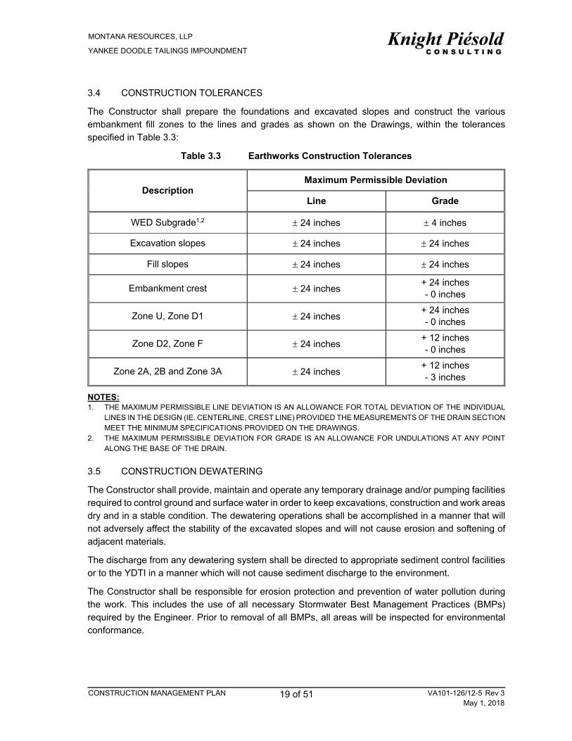
3.4 CONSTRUCTION TOLERANCES
The Constructor shall prepare the foundations and excavated slopes and construct the various embankment fill zones to the lines and grades as shown on the Drawings, within the tolerances specified in Table 3.3:
Table 3.3 Earthworks Construction Tolerances
Description Maximum Permissible Deviation
Line Grade
WED Subgrade1,2 24 inches 4 inches
Excavation slopes 24 inches 24 inches
Fill slopes 24 inches 24 inches
Embankment crest 24 inches + 24 inches - 0 inches
Zone U, Zone D1 24 inches + 24 inches - 0 inches
Zone D2, Zone F 24 inches + 12 inches - 0 inches
Zone 2A, 2B and Zone 3A 24 inches + 12 inches - 3 inches
NOTES: 1. THE MAXIMUM PERMISSIBLE LINE DEVIATION IS AN ALLOWANCE FOR TOTAL DEVIATION OF THE INDIVIDUAL
LINES IN THE DESIGN (IE. CENTERLINE, CREST LINE) PROVIDED THE MEASUREMENTS OF THE DRAIN SECTION MEET THE MINIMUM SPECIFICATIONS PROVIDED ON THE DRAWINGS.
2. THE MAXIMUM PERMISSIBLE DEVIATION FOR GRADE IS AN ALLOWANCE FOR UNDULATIONS AT ANY POINT ALONG THE BASE OF THE DRAIN.
3.5 CONSTRUCTION DEWATERING
The Constructor shall provide, maintain and operate any temporary drainage and/or pumping facilities required to control ground and surface water in order to keep excavations, construction and work areas dry and in a stable condition. The dewatering operations shall be accomplished in a manner that will not adversely affect the stability of the excavated slopes and will not cause erosion and softening of adjacent materials.
The discharge from any dewatering system shall be directed to appropriate sediment control facilities or to the YDTI in a manner which will not cause sediment discharge to the environment.
The Constructor shall be responsible for erosion protection and prevention of water pollution during the work. This includes the use of all necessary Stormwater Best Management Practices (BMPs) required by the Engineer. Prior to removal of all BMPs, all areas will be inspected for environmental conformance.

MONTANA RESOURCES, LLP
YANKEE DOODLE TAILINGS IMPOUNDMENT
CONSTRUCTION MANAGEMENT PLAN 20 of 51 VA101-126/12-5 Rev 3May 1, 2018
3.6 EARTHWORKS INSPECTION AND TEST PLAN
The Inspection and Test Plan detailed in Table 3.4 identifies the frequency and type of inspection, testing and documentation for the Earthworks components of the project.
Table 3.4 Earthworks Inspection and Test Plan
Activity Inspection
Requirement Testing
Requirement Documentation
Requirement Hold Point
Requirement
Clearing, Stripping and Grubbing
Minimum weekly Constructor Inspection.
None None None
Subgrade Preparation
Minimum twice weekly Constructor Inspection.
Engineer inspection of prepared subgrade (see note 1).
Proof rolling to the satisfaction of the Engineer.
Engineer to prepare SIR.
Constructor to prepare survey of limits of completed area.
Constructor to Hold for Engineer Inspection (see note 1).
Selection of External Borrow Sources
The Constructor and the Engineer will complete an inspection of the borrow sources.
Constructor to complete laboratory testing at the direction of the Engineer to assess the suitability of the borrow sources.
Constructor to prepare a Submittal comprising laboratory test results and other information.
Engineer to prepare a response to the Constructor Submittal.
Constructor to Hold for Engineer review of Submittal prior to procurement and production of engineered fills.
Fill Placement – Zone U, UA, D1, F and D2
Daily Constructor inspection.
Remote monitoring (see note 1) and minimum quarterly Engineer Inspection.
QC material testing by Constructor as per Table 3.2.
QA material testing by Engineer as per Section 3.3.8.
Constructor to prepare Monthly Submittal of QC documents.
Engineer to review submittals and document in
None ▲R3
MONTANA RESOURCES, LLP
YANKEE DOODLE TAILINGS IMPOUNDMENT
CONSTRUCTION MANAGEMENT PLAN 21 of 51 VA101-126/12-5 Rev 3May 1, 2018
Activity Inspection
Requirement Testing
Requirement Documentation
Requirement Hold Point
Requirement
QA Summary report.
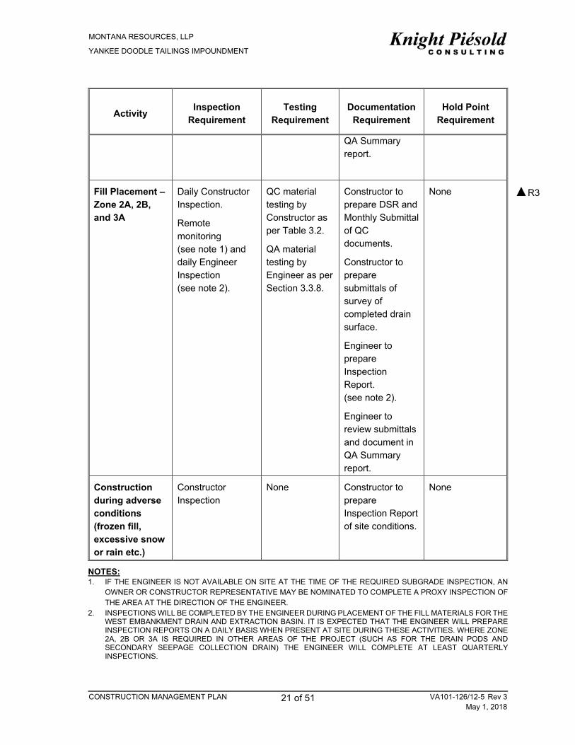
Fill Placement – Zone 2A, 2B, and 3A
Daily Constructor Inspection.
Remote monitoring (see note 1) and daily Engineer Inspection (see note 2).
QC material testing by Constructor as per Table 3.2.
QA material testing by Engineer as per Section 3.3.8.
Constructor to prepare DSR and Monthly Submittal of QC documents.
Constructor to prepare submittals of survey of completed drain surface.
Engineer to prepare Inspection Report. (see note 2).
Engineer to review submittals and document in QA Summary report.
None
Construction during adverse conditions (frozen fill, excessive snow or rain etc.)
Constructor Inspection
None Constructor to prepare Inspection Report of site conditions.
None
NOTES: 1. IF THE ENGINEER IS NOT AVAILABLE ON SITE AT THE TIME OF THE REQUIRED SUBGRADE INSPECTION, AN
OWNER OR CONSTRUCTOR REPRESENTATIVE MAY BE NOMINATED TO COMPLETE A PROXY INSPECTION OF THE AREA AT THE DIRECTION OF THE ENGINEER.
2. INSPECTIONS WILL BE COMPLETED BY THE ENGINEER DURING PLACEMENT OF THE FILL MATERIALS FOR THE WEST EMBANKMENT DRAIN AND EXTRACTION BASIN. IT IS EXPECTED THAT THE ENGINEER WILL PREPARE INSPECTION REPORTS ON A DAILY BASIS WHEN PRESENT AT SITE DURING THESE ACTIVITIES. WHERE ZONE 2A, 2B OR 3A IS REQUIRED IN OTHER AREAS OF THE PROJECT (SUCH AS FOR THE DRAIN PODS AND SECONDARY SEEPAGE COLLECTION DRAIN) THE ENGINEER WILL COMPLETE AT LEAST QUARTERLY INSPECTIONS.
▲R3

MONTANA RESOURCES, LLP
YANKEE DOODLE TAILINGS IMPOUNDMENT
CONSTRUCTION MANAGEMENT PLAN 22 of 51 VA101-126/12-5 Rev 3May 1, 2018
4 – GEOTEXTILE
4.1 SCOPE OF WORK
The portion of work specified in this section shall consist of supplying all labor, supervision, equipment and materials necessary to install and protect the geotextile materials as shown on the Drawings, or as required by the Engineer. Geotextiles are required throughout the WED and other auxiliary seepage management features.
4.2 SUBMITTALS
A copy of the manufacturer’s geotextile specification and technical documentation shall be submitted to the Engineer for approval prior to procurement.
Copies of the manufacturer’s QC certificates for the product shall be submitted to the Engineer prior to installation of the product. The quality control certificates shall include roll numbers and identification, results of the quality control tests and descriptions of the test methods used.
4.3 DELIVERY, HANDLING AND STORAGE OF GEOTEXTILES
Delivery, handling and storage of geotextile material shall be in accordance with the manufacturer’s instructions. Geotextile shall be packaged and shipped in standard roll lengths and widths. The geosynthetics shall be kept free of dirt, solvents, debris, rodents, and other conditions that, in the opinion of the Engineer, would affect the performance of the materials. The manufacturer’s label must remain intact until the time of installation.
Geotextiles shall be kept dry and wrapped such that it is protected from the elements during shipping and storage. At no time shall the geotextile be exposed to ultraviolet light for a period exceeding 14 days. The geotextile shall be labelled as per ASTM D4873.
4.4 GEOTEXTILE SPECIFICATION
Geotextile material shall be non-woven needle punched material that meets the test methods and specifications defined in Table 4.1.
Table 4.1 Geotextile Specifications
Tested Property Test Method Minimum Average Value
Weight ASTM D3776 300 gm/m2 (0.03 oz/yd2)
Grab Strength ASTM D4632 1,112 N (250 lbs)
Elongation at Break ASTM D4632 50%
Apparent Opening Size ASTM D4751 150 Micron
Puncture ASTM D6241 535 N (120 lbs)
Trapezoidal Tear Strength ASTM D4533 445 N (100 lbs)
UV Resistance (at 500 hours) ASTM D7238 70% Strength Retained
Geotextile shall consist of a material composed of at least 85 percent by weight of polyolefins, polyesters, or polyamides. It will be resistant to chemical attack, rot and mildew, and will have no tears or defects, which adversely alter its physical properties.

MONTANA RESOURCES, LLP
YANKEE DOODLE TAILINGS IMPOUNDMENT
CONSTRUCTION MANAGEMENT PLAN 23 of 51 VA101-126/12-5 Rev 3May 1, 2018
Propex Geotex 1001 in a non-woven geotextile that satisfies the above specifications. Equivalent non-woven geotextile may be accepted for use. Product data sheets may be formally submitted to the Engineer for approval.
4.5 INSTALLATION PROCEDURES
The geotextile shall be handled in such a manner that it is not damaged during transport and installation.
The geotextile shall be laid flat and smooth on the prepared subgrade so that it is in direct contact with the subgrade. The geotextile shall be free of tensile stresses, folds and wrinkles so that the overlying materials will not excessively stretch or tear the fabric. On slopes steeper than 10H:1V, the geotextile shall be laid with the machine direction of the fabric parallel to the slope direction. Anchoring of the terminal ends of the geotextile shall be accomplished through the use of key trenches or aprons at the crest and toe of the slope as outlined in the Drawings.
Successive and adjacent sheets shall be overlapped a minimum of 12 inches in such a manner that the upslope sheet overlaps the downslope sheet. The overlying material placement shall begin at the toe and proceed up the slope.
The geotextile shall be covered as soon as possible after installation and inspection. Installed geotextile shall not be left exposed for more than 7 days. Material overlying the geotextile shall be carefully placed to avoid wrinkling or damage to the geotextile.

MONTANA RESOURCES, LLP
YANKEE DOODLE TAILINGS IMPOUNDMENT
CONSTRUCTION MANAGEMENT PLAN 24 of 51 VA101-126/12-5 Rev 3May 1, 2018
4.6 GEOTEXTILE INSPECTION AND TEST PLAN
The Inspection and Test Plan detailed in Table 4.2 identifies the frequency and type of inspection, testing and documentation for the Geotextile procurement and installation.
Table 4.2 Geotextile Inspection and Test Plan
Activity Inspection
Requirement Testing
RequirementDocumentation
Requirement Hold Point
Requirement
Procurement Constructor inspection following receipt of product.
None Constructor to prepare submittal of manufacturer’s technical information and QC documentation.
Engineer to provide a response to the Constructor submittal.
Constructor to hold procurement and installation of product until approval of submittal by the Engineer.
Subgrade Preparation
As per Earthworks ITP
Installation Daily Constructor Inspection.
Remote monitoring (see note 1) and daily to monthly Engineer Inspection (see note 2).
None Engineer to prepare Inspection Report (see note 2).
Engineer to review submittals and document in the QA report.
None
NOTES: 1. IF THE ENGINEER IS NOT AVAILABLE ON SITE AT THE TIME OF THE REQUIRED INSPECTION, AN OWNER OR
CONSTRUCTOR REPRESENTATIVE MAY BE NOMINATED TO COMPLETE A PROXY INSPECTION OF THE INSTALLATION AT THE DIRECTION OF THE ENGINEER.
2. INSPECTIONS WILL BE COMPLETED BY THE ENGINEER DURING INSTALLATION OF THE GEOTEXTILE FOR THE WEST EMBANKMENT DRAIN AND EXTRACTION BASIN. IT IS EXPECTED THAT THE ENGINEER WILL PREPARE INSPECTION REPORTS ON A DAILY BASIS WHEN PRESENT ON SITE FOR THESE ACTIVITIES. WHERE GEOTEXTILE IS REQUIRED IN OTHER AREAS OF THE PROJECT (SUCH AS FOR THE DRAIN PODS AND SECONDARY SEEPAGE COLLECTION DRAIN) THE ENGINEER WILL COMPLETE QUARTERLY INSPECTIONS.

MONTANA RESOURCES, LLP
YANKEE DOODLE TAILINGS IMPOUNDMENT
CONSTRUCTION MANAGEMENT PLAN 25 of 51 VA101-126/12-5 Rev 3May 1, 2018
5 – GEOMEMBRANE LINERS
5.1 SCOPE OF WORK
The portion of work specified in this section shall consist of supplying all labor, supervision, equipment and materials necessary to install and protect the geomembrane materials as shown on the Drawings, or as required by the Engineer. Smooth HDPE geomembrane will be installed at the following locations along the West Embankment Drain:
Downstream of the Rocky Knob cut, between the non-woven geotextile layers within the WED, and
Extraction Pond.
5.2 SUBMITTALS
A copy of the manufacturer’s geomembrane specification and technical documentation shall be submitted to the Engineer for approval prior to procurement.
Copies of the manufacturer’s QC certificates for the product shall be submitted to the Engineer prior to installation of the product. The quality control certificates shall include roll numbers and identification, results of the quality control tests and descriptions of the test methods used.
5.3 GEOMEMBRANE QUALIFICATIONS
Installation of the geomembrane is to be undertaken by an approved specialist Constructor who is responsible for the field handling, transporting, storing, deploying, seaming and testing of the geomembrane seams.
The Constructor shall have completed a minimum of 1,000,000 square feet of HDPE flexible lining material installation. A project Superintendent or Installation Supervisor shall be provided by the Geosynthetics Constructor and shall be in charge of the installation.
5.4 DELIVERY, HANDLING AND STORAGE OF GEOMEMBRANE
Delivery handling and storage of geomembrane material shall be in accordance with the manufacturer’s instructions. Geomembrane shall be packaged and shipped in standard roll lengths and widths.
The geosynthetics shall be kept free of dirt, solvents, debris, rodents, and other conditions that, in the opinion of the Engineer, would affect the performance of the materials. The manufacturer’s label must remain intact until the time of installation. The geomembrane shall be labelled as per ASTM D5641.
5.5 GEOMEMBRANE SPECIFICATION
The geomembrane liner shall be of high quality formulation, containing approximately 97% polymer and 3% carbon black with anti-oxidants and heat stabilizers. It shall be resistant to ultraviolet rays. The geomembrane shall be an HDPE material manufactured of new, first-quality products designed and manufactured specifically for the purpose of liquid containment in hydraulic structures. The finished material shall be free of holes, blisters, undispersed raw materials, or any sign of contamination by foreign matter.
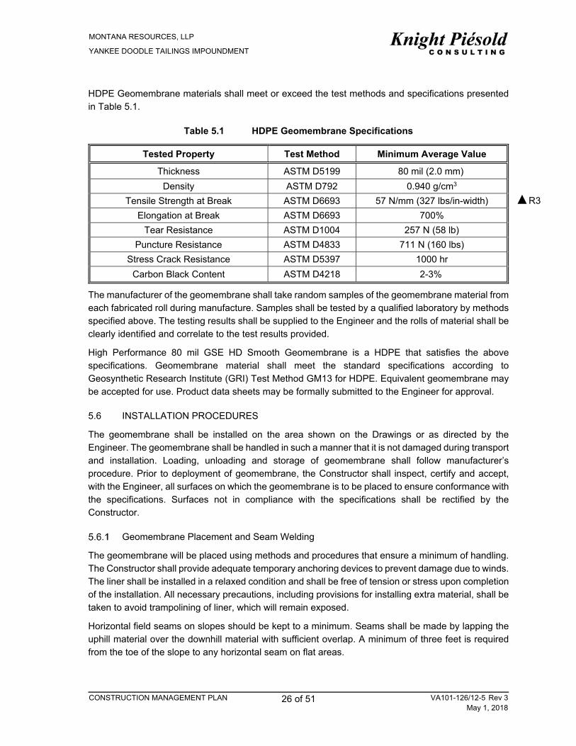
MONTANA RESOURCES, LLP
YANKEE DOODLE TAILINGS IMPOUNDMENT
CONSTRUCTION MANAGEMENT PLAN 26 of 51 VA101-126/12-5 Rev 3May 1, 2018
HDPE Geomembrane materials shall meet or exceed the test methods and specifications presented in Table 5.1.
Table 5.1 HDPE Geomembrane Specifications
Tested Property Test Method Minimum Average Value
Thickness ASTM D5199 80 mil (2.0 mm)
Density ASTM D792 0.940 g/cm3
Tensile Strength at Break ASTM D6693 57 N/mm (327 lbs/in-width)
Elongation at Break ASTM D6693 700%
Tear Resistance ASTM D1004 257 N (58 lb)
Puncture Resistance ASTM D4833 711 N (160 lbs)
Stress Crack Resistance ASTM D5397 1000 hr
Carbon Black Content ASTM D4218 2-3%
The manufacturer of the geomembrane shall take random samples of the geomembrane material from each fabricated roll during manufacture. Samples shall be tested by a qualified laboratory by methods specified above. The testing results shall be supplied to the Engineer and the rolls of material shall be clearly identified and correlate to the test results provided.
High Performance 80 mil GSE HD Smooth Geomembrane is a HDPE that satisfies the above specifications. Geomembrane material shall meet the standard specifications according to Geosynthetic Research Institute (GRI) Test Method GM13 for HDPE. Equivalent geomembrane may be accepted for use. Product data sheets may be formally submitted to the Engineer for approval.
5.6 INSTALLATION PROCEDURES
The geomembrane shall be installed on the area shown on the Drawings or as directed by the Engineer. The geomembrane shall be handled in such a manner that it is not damaged during transport and installation. Loading, unloading and storage of geomembrane shall follow manufacturer’s procedure. Prior to deployment of geomembrane, the Constructor shall inspect, certify and accept, with the Engineer, all surfaces on which the geomembrane is to be placed to ensure conformance with the specifications. Surfaces not in compliance with the specifications shall be rectified by the Constructor.
Geomembrane Placement and Seam Welding
The geomembrane will be placed using methods and procedures that ensure a minimum of handling. The Constructor shall provide adequate temporary anchoring devices to prevent damage due to winds. The liner shall be installed in a relaxed condition and shall be free of tension or stress upon completion of the installation. All necessary precautions, including provisions for installing extra material, shall be taken to avoid trampolining of liner, which will remain exposed.
Horizontal field seams on slopes should be kept to a minimum. Seams shall be made by lapping the uphill material over the downhill material with sufficient overlap. A minimum of three feet is required from the toe of the slope to any horizontal seam on flat areas.
▲R3

MONTANA RESOURCES, LLP
YANKEE DOODLE TAILINGS IMPOUNDMENT
CONSTRUCTION MANAGEMENT PLAN 27 of 51 VA101-126/12-5 Rev 3May 1, 2018
Extreme care shall be taken by the Constructor in the preparation of the areas to be welded. The area to be welded shall be cleaned and prepared according to the approved procedures, and all sheeting shall be welded together by thermal methods.
The welding equipment used shall be capable of continuously monitoring and controlling the temperatures in the zone of contact where the machine is actually fusing the lining material, to ensure changes in weather conditions will not affect the integrity of the weld. Welding equipment and accessories shall meet the following requirements:
Gauges showing temperatures in apparatus such as extrusion welder or fusion welder shall be present
An adequate number of welding apparati shall be available to avoid delaying work, and
Power source must be capable of providing constant voltage under combined line load.
No “fish mouths” shall be allowed within the seam area. Where “fish mouths” occur, the material shall be cut, overlapped, and extrusion welded. All welds on completion of the Work shall be tightly bonded. Any membrane area showing distress due to excessive scuffing or puncture from any cause shall be replaced or repaired.
The Constructor shall take into account that rapid weather changes are very possible, resulting in delays in construction of field seams. Jointing of panels and repairs will only be permitted under weather conditions allowing such work within the warranty limits imposed by the liner manufacturer.
No geomembrane material shall be seamed when the liner temperature is less than 32 degrees F unless the following conditions are met:
The Constructor can demonstrate to the Engineer using prequalification test seams that field seams comply with the project specifications, the safety of the crew is ensured and geomembrane material can be fabricated (i.e. pipe boots, penetrations, repairs, etc.) at sub-freezing temperatures.
The Constructor shall submit to the Engineer for approval detailed procedures for seaming at low temperatures including the following: o Preheating of the geomembrane o The provision of a tent or other shelter if necessary to prevent heat losses during seaming and
rapid heat losses subsequent to seaming, and o Number of test welds to determine appropriate seaming parameters.
No geomembrane material shall be seamed when the liner temperature is above 170 degrees F as measured by an infrared thermometer or surface thermocouple, unless otherwise approved by the Engineer.
5.7 GEOMEMBRANE INSPECTION AND TEST PLAN
A maximum effort shall be made to install a perfect liner. This means that all seams completed in the field, patches and extrusions shall be inspected, tested, and recorded.
A Constructor quality control technician shall inspect each seam, marking his initials and the date inspected at the end of each panel. Any area showing a defect shall be marked and repaired in accordance with the geomembrane repair procedure.
All field sampling and testing shall be done by the Constructor as approved by the Engineer.

MONTANA RESOURCES, LLP
YANKEE DOODLE TAILINGS IMPOUNDMENT
CONSTRUCTION MANAGEMENT PLAN 28 of 51 VA101-126/12-5 Rev 3May 1, 2018
The field installation testing program shall consist of periodic visual observations, continuity, and strength tests. These inspections and tests are to be made routinely and are automatic regardless of other types of testing required. The program shall include:
Visual observations are to be made routinely and shall include the following: o Visually check field seams for squeeze out, foot print, melt and overlap o Check machines for cleanness, temperature and related items, and o Any area of the seam or panel showing a defect shall be marked and repaired in accordance
with the applicable repair procedures.
Continuity testing is required for all field seams and repaired areas. Inter-seam pressure or “air testing” and testing using vacuum box are considered acceptable methods for continuity testing. The test procedures for inter-seam pressure or air testing is the following: o Seal both ends of the seam to be tested by applying heat to the end of the seam until flow
temperature is achieved. Clamp off the ends and let cool o Insert a pressure gauge/needle assembly into the end of the seam and seal, and o Apply air pressure to the void between the two seams according to the following schedule in
Table 5.2.
Table 5.2 HDPE Geomembrane Air Channel Seam Testing Requirements
HDPE INITIAL PRESSURE SCHEDULE
Material HDPE Thickness Pressure Range (psi) Allowable leak down after 5 minutes (psi) Minimum Maximum
80mil, 100 mil 28 30 4
The initial start pressure is read after a 2-minute relaxing period, which allows the air to reach ambient liner temperature; the ending pressure is read after 5 minutes.
The results of the leak test shall be marked at the test location and shall be recorded by the Constructor. If the test fails, the location of the leak shall be found and repaired or the entire seam shall be repaired and retested.
The test procedure for vacuum box testing is as follows:
Mix a solution of liquid detergent and water and apply an ample amount to the area to be tested. If a seam contains excess overlap or loose edges it is to be trimmed before testing
Place a translucent vacuum box over the area and apply a slight amount of downward pressure to the box to the seal strip to the liner, and
Apply a vacuum (3 psi to 5 psi) to the area. Any leaks will become visible by large bubbles and shall be repaired.
Strength Testing
For trial welds, the following procedure is to be used:
Trial welds shall be completed under the same conditions and using the same materials, pre-seaming and seaming techniques as used to fabricate field seams. The trial weld samples shall be a minimum of 10 ft long by 1 ft wide for hot wedge seams and 3 ft long by 1 ft wide for extrusion seams, marked with the date, technician’s name, ambient temperature and welding machine number and temperature. 2 coupons from each end of the test weld (4 coupons in total)

MONTANA RESOURCES, LLP
YANKEE DOODLE TAILINGS IMPOUNDMENT
CONSTRUCTION MANAGEMENT PLAN 29 of 51 VA101-126/12-5 Rev 3May 1, 2018
shall be tested for peel and bonded seam strength using a calibrated tensiometer, as well as thickness, in accordance with the applicable ASTM or GRI standards as appropriate. Trial weld specimens shall pass if the results achieve the minimum seam strength values listed in Section 5.5. If one or more coupons fail the specimen will be considered a failure. Each coupon must fail in the parent material and not in the weld, “Film Tear Bond” (FTB) failure. Seam separation equal to or greater than 25% of the track width shall be considered a failing test.
If failing results occur, an additional trial weld shall be immediately conducted. If the additional trial weld fails the welding machine shall be rejected and not used until the deficiencies are corrected and a successful test seam can be produced.
The minimum frequency for obtaining trial weld samples from each of the welding machines in operation is the following:
Prior to the beginning of seaming operations
After every four hours of seaming operation
After repairs have been made to the seaming equipment
By each technician using the seaming equipment, and
As required by the Engineer.
For destructive testing of field seams the following procedures is to be used:
Destructive samples may be obtained from field seams or repaired areas by cutting perpendicular to the seams. The sample should be approximately 2 feet long by 1 foot wide. This sample shall be cut into two samples of 1 foot by 1 foot and labeled with the welder identification, date and location. One of the samples will be retained by the Engineer and one of the samples will be tested by the Constructor, using a calibrated tensiometer, in accordance with the applicable ASTM or NSF 54 standards as appropriate.
The frequency for obtaining destructive test samples shall not be less than one sample per 500 feet of field seams. Coupons from the destructive sample shall be tested for peel and bonded seam strength as well as thickness, in accordance with the applicable ASTM standards. If one or more of the coupon fails, the sample will be considered a failure.
In the event of a failing test result, additional samples, on either side of the failure, shall be tested to isolate the portion of the weld shall be “capped”. Alternatively, the entire seam can be re-welded and retested.
The Inspection and Test Plan detailed in Table 5.3 identifies the frequency and type of inspection, testing and documentation for the Geomembrane procurement and installation.

MONTANA RESOURCES, LLP
YANKEE DOODLE TAILINGS IMPOUNDMENT
CONSTRUCTION MANAGEMENT PLAN 30 of 51 VA101-126/12-5 Rev 3May 1, 2018
Table 5.3 Geomembrane Inspection and Test Plan
Activity Inspection
RequirementTesting
Requirement Documentation
Requirement Hold Point
RequirementProcurement Constructor
inspection following receipt of product
None Constructor to prepare submittal of manufacturers technical information and QC documentation. Engineer to provide a response to the Constructor submittal.
Constructor to hold procurement and installation of product until approval of submitttal by the Engineer.
Subgrade Preparation
As per Earthworks ITP
Installation
Daily Constructor Inspection.
Testing required as specified by Constructor of material and as listed in Section 5.7.
All tests to be documented and results recorded and submitted to the Engineer for review.
Seam Welding
Visual Inspection
Visually check seams for: squeeze out, footprints, melting, and overlap as listed in Section 5.7. Inspect machines for cleanliness, temperature and related items
All seams shall be inspected by Constructor quality control technician, marking initials and date of inspection. Any area showing defect shall be repaired according to Liner repair procedures.
Testing Field testing to be completed according to manufacturers procedures by the Constructor and as listed in Section 5.7.
Proof of testing and results to be supplied to the Engineer
NOTES: 1. IF THE ENGINEER IS NOT AVAILABLE ON SITE AT THE TIME OF THE REQUIRED INSPECTION, AN OWNER OR
CONSTRUCTOR REPRESENTATIVE MAY BE NOMINATED TO COMPLETE A PROXY INSPECTION OF THE INSTALLATION AT THE DIRECTION OF THE ENGINEER.
2. INSPECTIONS WILL BE COMPLETED BY THE ENGINEER DURING INSTALLATION OF THE GEOTEXTILE FOR THE WEST EMBANKMENT DRAIN AND EXTRACTION BASIN. IT IS EXPECTED THAT THE ENGINEER WILL PREPARE INSPECTION REPORTS ON A DAILY BASIS WHEN PRESENT ON SITE FOR THESE ACTIVITIES. WHERE GEOTEXTILE IS REQUIRED IN OTHER AREAS OF THE PROJECT (SUCH AS FOR THE DRAIN PODS AND SECONDARY SEEPAGE COLLECTION DRAIN) THE ENGINEER WILL COMPLETE QUARTERLY INSPECTIONS.
▲R3
▲R3
▲R3

MONTANA RESOURCES, LLP
YANKEE DOODLE TAILINGS IMPOUNDMENT
CONSTRUCTION MANAGEMENT PLAN 31 of 51 VA101-126/12-5 Rev 3May 1, 2018
5.8 GEOMEMBRANE REPAIR PROCEDURE
If a repair of the geomembrane is required the damaged geomembrane is to be removed and replaced with acceptable geomembrane materials if damage cannot be satisfactorily repaired. The Constructor shall be responsible to repair any portion of unsatisfactory geomembrane or seam area failing a destructive or non-destructive test.
Before completion of any repairs an agreement upon the appropriate repair method shall be decided between the Engineer and the Constructor. The following repair methods may be implemented: 1. Patching: Used to repair large holes, tears, undispersed raw materials and contamination by
foreign matter. 2. Abrading and Re-welding: Used to repair short section of a seam. 3. Spot Welding: Used to repair pinholes or other minor, localized flaws or where geomembrane
thickness has been reduced. 4. Capping: Used to repair long lengths of failed seams. 5. Remove the unacceptable seam and replace with new material.
The following procedures shall be observed when a repair method is used: 1. All geomembrane surfaces shall be clean and dry at the time of repair. 2. Surfaces of the polyethylene which are to be repaired by extrusion welds shall be lightly abraded
to assure cleanliness. 3. Extend patches or caps at least 6 inches for extrusion welds and 4 inches for wedge welds beyond
the edge of the defect, and around all corners of patch material.
Upon completion the quality of the repair is to be logged and verified by the Constructor and Engineer using non-destructive testing methods outlined in this Specification.

MONTANA RESOURCES, LLP
YANKEE DOODLE TAILINGS IMPOUNDMENT
CONSTRUCTION MANAGEMENT PLAN 32 of 51 VA101-126/12-5 Rev 3May 1, 2018
6 – CONCRETE
6.1 SCOPE OF WORK
The portion of the work described in this section will consist of the construction of the concrete components of the work as shown on the Drawings. Specific details relating to the individual concrete components are included on the applicable Drawings, and are to be reviewed along with this document prior to any concrete placement.
6.2 CONCRETE FORMWORK AND FALSEWORK
All falsework and formwork required for cast-in-place concrete shall be executed in accordance with the American Concrete Institute (ACI) publication 347 – Guide to Formwork for Concrete.
Formwork Design and Materials
Design and engineering of formwork, shoring and falsework is the responsibility of the Constructor. Retain a Professional Engineer or approved designer to provide complete designs, drawings and instructions for forms, falsework, shoring and re-shoring for the project.
Formed surface finishes are to be detailed on the specific concrete Drawings. All concrete corners (exposed or un-exposed) shall have a 1-inch chamfer formed from a 1 x 1-inch triangular timber strip, unless specified otherwise on the Drawings.
Formwork Removal
Formwork should not be removed until the concrete has attained sufficient strength to prevent damage by removal of the forms or by subsequent construction activities and associated loads, such as nearby backfilling and compaction. Formwork for foundations are not to be removed for a minimum of 48 hours after placing concrete.
Formwork Inspections
Formwork inspections are not considered hold points of the design and remain the responsibility of the Constructor, however the Engineer may inspect forms prior to placing concrete solely for purpose of reviewing cleanliness, and for general conformance with the Drawings, as outlined in Table 6.1. Such inspection will not relieve the Constructor of the responsibility to construct and erect forms safely.
6.3 CONCRETE STEEL REINFORCEMENT
This section refers to all reinforcement steel for cast-in-place and precast concrete shown or indicated on the Drawings. All reinforcement shall be executed in accordance with the ACI publication 315 – Details and Detailing of Concrete Reinforcement.
Reinforcement Detailing
The Constructor shall be responsible for correctness of measured dimensions and report to the Engineer, in writing, all discrepancies between measurements and those shown on the Drawings prior to commencing Work.
Detailing of reinforcement, such as bar size and spacing, minimum concrete to reinforcement cover, splice and lap length, and embedment depth, are included on specific reinforcement and structural

MONTANA RESOURCES, LLP
YANKEE DOODLE TAILINGS IMPOUNDMENT
CONSTRUCTION MANAGEMENT PLAN 33 of 51 VA101-126/12-5 Rev 3May 1, 2018
drawings. Special requirements, such as accommodation of inserts, blockouts, conduits and openings will be detailed on the Drawings.
Steel reinforcement supplied shall be deformed bar reinforcement for structural concrete that shall comply with ASTM A615 ‘Standard Specification for Deformed and Plan Carbon-Steel Bars for Concrete Reinforcement’, unless otherwise noted on the Drawings. The supplied steel reinforcement shall have a minimum yield strength of 60 ksi.
Reinforcement Inspections and Tolerance
The Engineer’s approval of the installed reinforcement must be obtained before placing concrete, with all reinforcement steel in place for the section of work being constructed, as outlined in Table 6.1.
Depending on the extent and significance of the concrete works, it may be requested that the Constructor provide the Engineer with reinforcement shop drawings for review and approval prior to the procurement of the steel reinforcement. The Constructor shall confirm with the Engineer whether shop drawing review of the reinforcement is required prior to placement.
Place reinforcement within the following tolerances:
On concrete cover: -0 inch, + 1/2 inch
On effective depth (from face to opposite face): -1/2 inch, +1/2 inch
On embedment and splice length: -0 inch, No upper limit
On standard hook dimensions: -0 inch, No upper limit
On lateral spacing of reinforcement: -1/2 inch, +1/2 inch
On rebar dimension length: -1 inch, +1 inch, and
On overall tie bar and stirrup dimension: -1/4 inch, +1/4 inch.
Where no upper limit is specified for tolerances the Engineer may request excess be cut at their discretion is overcrowding of the reinforcement is observed that may inhibit the flow of concrete around the reinforcing bar.
6.4 CAST-IN-PLACE CONCRETE
This section refers to all cast-in-place concrete and finishes shown or indicated on the Drawings. All reinforcement shall be executed in accordance with the following ACI publications:
ACI 211.1 - Standard Practice for Selecting Proportions for Normal, Heavyweight, and Mass Concrete
ACI 305.1 - Specification for Hot Weather Concreting
ACI 306.1 - Guide to Cold Weather Concreting
ACI 308.1 - Specification for Curing of Concrete
ACI 309R - Guide for Consolidation of Concrete, and
ACI 315 - Details and Detailing of Concrete Reinforcement.
Submittals and Supplier
Depending of the extent and significance or if requested, the Constructor shall submit a copy of the proposed concrete mix design(s) to the Engineer before any concrete is placed on site. The minimum compressive strength shall be as specified on the drawings. The concrete supplied for the project shall be supplied by a commercial concrete supplier.

MONTANA RESOURCES, LLP
YANKEE DOODLE TAILINGS IMPOUNDMENT
CONSTRUCTION MANAGEMENT PLAN 34 of 51 VA101-126/12-5 Rev 3May 1, 2018
Quality Control and Assurance
The Constructor shall appoint a quality control officer and/or independent testing agent, who will carry out the following at the Constructors expense:
Review the proposed mix designs to ensure it is consistent with the compressive strength specified on the drawings.
Take samples of concrete as it is delivered to the point of final deposit. Make one set of three test cylinders for every 50 cubic metres of concrete placed but not less than one set each day if less than 50 cubic metres of the same type of concrete are placed.
Record the total concrete volume, concrete temperature, air temperature, location of pour, mix number and element type for each set of test cylinders made.
Make one additional concrete cylinder during cold weather when air temperature is forecast below 5° C (41°F) within 72 hours of concrete placement. Test additional cylinder as directed by the Engineer.
Test concrete for air content and slump from each day's pour at the time that concrete cylinders are made.
Test one cylinder at 7 days and two cylinders at 28 days. Compressive strength is defined as the average strength of the two 28 day cylinders taken from a single batch.
Notify the Constructor and the Engineer immediately if the results of these tests are not in accordance with the Specifications.
Send copies of all test results to the Engineer and Constructor.
These quality control measures may be undertaken by the chosen concrete supplier.
If testing of concrete cylinders indicates the concrete strength below the specified strength, core samples of the in-situ concrete shall be taken and tested to verify that the concrete meets the specifications. The costs of all retesting and remedial work to repair concrete, if required, shall be borne by the Constructor. In the event that the concrete does not meet the specified requirements after retesting, the Engineer shall have the right to require remedial measures or to require that the sub-standard concrete be removed and replaced at no extra cost to the Owner.
Site Conditions
Cold Weather Conditions: The Constructor shall comply with all the requirements of ACI 306 for placing of concrete when the air temperature falls below 5°C (41°F). No concrete shall be placed if ambient temperature is less than 0°C (32°F), unless protective enclosures and heating are provided 12 hours prior to concrete placement and maintained for a minimum of 72 hours following concrete placement. No concrete shall be placed against reinforcement which is below 0°C (32°F).
Hot Weather Conditions: The Constructor shall comply with ACI 305 for placing of concrete when the air temperature is above 30°C (86°F).
Freshly placed and green concrete shall be protected from damage caused by rain, snow, sun, wind and construction hazards during and after placement, thereof. Exposed concrete corners and hardened concrete surfaces shall be protected for the duration of the construction period, in order to prevent chipping and staining.

MONTANA RESOURCES, LLP
YANKEE DOODLE TAILINGS IMPOUNDMENT
CONSTRUCTION MANAGEMENT PLAN 35 of 51 VA101-126/12-5 Rev 3May 1, 2018
Concrete Materials and Placement
Concrete materials and admixtures are defined on associated concrete Drawings. Concrete mixes are to confirm to ACI 211. Concrete type and strength requirements are detailed on the Drawings.
Concrete shall not be mixed while the air temperature is below 5°C (41°F) without permission of the Engineer. The Constructor is responsible for any defective work resulting from freezing during placing and curing and shall replace concrete not meeting these specifications at no extra cost to the Owner. Do not mix concrete if the air temperature is above 30°C (86°F).
Concrete shall not be placed in formwork, if temperature inside form is less than 5°C (41°F). Preheat forms to maintain temperature at 5°C (41°F) or above. Concrete shall not be placed in formwork which has collected water ponding in it, snow or ice, in any form or manner.
Formwork shall be cleaned of all tie wire off-cuts, nuts, bolts, rebar off-cuts, timber and other debris before fresh concrete is placed inside forms.
Concrete shall not be placed until the formwork and the placement of reinforcement has been inspected by the Engineer. Concrete placement and compaction shall be completed in accordance with ACI 305. When the air temperature rises above 30°C (86°F) requirements of ACI 305 must be met, and when the air temperature falls below 5°C (41°F), concrete is to be placed in accordance with ACI 306.
Concrete is to be placed as close as possible to its final position to avoid segregation of the coarse aggregate, mortar or water from the concrete mass. Appropriate equipment which will prevent separation of coarse aggregate from the concrete is to be provided by the Constructor. Maintain at least one spare (standby) vibrator on site during concrete placement. Carry out placing as a continuous operation until placement of the panel or section is complete. Do not deposit fresh concrete on concrete, which has hardened sufficiently that a vibrator will not easily penetrate.
Concrete joints are to be located only where and if specified on the Drawings, or where approved by the Engineer. Special requirements, such as accommodation of inserts, blockouts, conduits, and openings will be detailed on the Drawings.
Surface Finishes and Tolerance Limits
Concrete surface finishes shall be established as outlined on the Drawings. General tolerance of concrete works is defined on the Drawings. Concrete work not meeting the tolerance limits as specified, is deemed defective and must be removed and rebuilt or repaired as directed by the Engineer.
Concrete Curing
All concrete is to be cured and protected from rain, flowing water and mechanical damage. Initial curing period is considered to be 7 days without interruption. Do not allow any part of the concrete surface to become dry or the air temperature to go below 5°C (41°F) or exceed 30°C (86°F), even for a short period of time.
Maintain concrete above 10°C (50°F) during the initial curing period. When using heating units, wet down exposed concrete surfaces within the vicinity of heating units with a hose stream at least once every 4 hours and prevent drying of the concrete around any heating units. At the end of the curing

MONTANA RESOURCES, LLP
YANKEE DOODLE TAILINGS IMPOUNDMENT
CONSTRUCTION MANAGEMENT PLAN 36 of 51 VA101-126/12-5 Rev 3May 1, 2018
period, discontinue artificial heating such that the fall in temperature at any point in the concrete will not exceed 5°C (41°F) in 24 hours.
Fill shall not be placed against concrete until a minimum of seven days has elapsed after concrete placement unless approved by the Engineer or proof of early sufficient strength by way of advance cylinder testing is provided.
Concrete Repairs and Grouting
Concrete work considered to be defective by the Engineer will be subject to repair. The repair procedure will be outlined by the Engineer based on the extent of the damage or level of non-conformance (ie. concrete placed outside of tolerance limits).
Non-shrink grout and epoxy grout/adhesive may be specified by the Engineer for use in the design, or as products to complete repairs. Details specific to grout use are outlined on the Drawings.
Concrete Inspections
The Engineer’s approval shall be obtained for the correctness of all reinforcement and formwork (as it relates to the overall dimensions and cover) before placing concrete, as outlined in Table 6.1. All reinforcement steel must be in place for the section of work being constructed prior to the Engineer inspection. Incomplete work will not be accepted for placing concrete.
6.5 CONCRETE INSPECTION AND TEST PLAN
The Inspection and Test Plan detailed in Table 6.1 identifies the frequency and type of inspection, testing and documentation for the concrete construction.

MONTANA RESOURCES, LLP
YANKEE DOODLE TAILINGS IMPOUNDMENT
CONSTRUCTION MANAGEMENT PLAN 37 of 51 VA101-126/12-5 Rev 3May 1, 2018
Table 6.1 Concrete Inspection and Test Plan
Activity Inspection
Requirement Testing
RequirementDocumentation
Requirement Hold Point
requirement
Reinforcement Procurement
Constructor inspection following receipt of product.
None Shop drawing review by Engineer if requested.
None
Subgrade Preparation
As per Earthworks ITP
Reinforcement and Formwork Placement
Engineer Inspection of reinforcement as per Section 6.4. (see Note 1).
None Engineer to prepare Inspection Report detailing the reinforcement installation.
Constructor to Hold for Engineer Inspection (see note 1).
Concrete Pour Engineer Inspection of concrete pour as per Section 6.4 unless alternate instruction given during inspection of reinforcement. (see Note 1).
Concrete testing as detailed in Section 6.4 to be completed by the Constructor.
Constructor to prepare Submittal of concrete suppliers QC documents.
Engineer to provide a response to the Constructor’s submittal.
Constructor to Hold for Engineer Inspection unless alternate instruction given during inspection of reinforcement. (see Note 1).
NOTES: 1. IF THE ENGINEER IS NOT AVAILABLE ON SITE AT THE TIME OF THE REQUIRED INSPECTION, AN OWNER OR
CONSTRUCTOR REPRESENTATIVE MAY BE NOMINATED TO COMPLETE A PROXY INSPECTION OF THE AREA AT THE DIRECTION OF THE ENGINEER. PROOF OF INSPECTION IF CARRIED OUT BY OTHERS INCLUDING INSPECTION RECORD AND PHOTOGRAPHS SHALL BE SUBMITTED AS PART OF THE QUALITY DOCUMENTATION.
▲R3
▲R3

MONTANA RESOURCES, LLP
YANKEE DOODLE TAILINGS IMPOUNDMENT
CONSTRUCTION MANAGEMENT PLAN 38 of 51 VA101-126/12-5 Rev 3May 1, 2018
7 – PIPEWORKS AND APPURTENANCES
7.1 SCOPE OF WORK
The portion of the work described in this Section consists of the procurement, installation, inspection and testing of all equipment and materials necessary to install the pipework and appurtenances as shown on the Drawings including:
Supply and install all Steel and HDPE pipework and fittings for the West Embankment Drain Extraction Basin
Supply and install vertical turbine pumps and motors in the West Embankment Drain Extraction Basin, and
Supply and install instrumentation including flow meters, pressure transducers and air valves in the West Embankment Drain Extraction Basin.
Technical specifications and Inspection and Test Plans for the Reclaim and Tailings Distribution systems are not included in this document.
7.2 APPLICABLE SPECIFICATIONS AND REGULATIONS
All materials procured by the Constructor shall be new, suitable and the best of their respective kind and shall be subject to approval by the Engineer. They shall comply with the latest applicable standards for pipeworks including, but not limited to, the following:
American National Standards Institute (ANSI)
American Society of Mechanical Engineers (ASME)
American Society for Testing and Materials (ASTM), and
American Water Works Association (AWWA).
Any contradictions between standards shall be submitted to the Engineer for decision.
7.3 SUBMITTALS
The Constructor shall submit to the Engineer one copy of the manufacturer’s catalogues prior to procurement of the pipework and appurtenances. For pipe fittings and related pipework components, catalogues will include detailed information on material specifications, performance data, dimensions and pressure ratings, storage and handling requirements, installation and joining procedures, name and location of manufacturer’s representative, inspection and test plans, operation and maintenance manuals.
7.4 DELIVERY, HANDLING AND STORAGE OF PIPEWORKS AND APPURTENANCES
Pipe, pumps, fittings, valves and other appurtenances shall be loaded and unloaded by lifting with hoists in such a manner as to avoid damage or hazard. Under no circumstances shall the pipe or pipe fittings be dropped to the ground or into trenches. Pipe shall not be skidded or rolled against pipe already on the ground. The interior of all pipes, fittings and valves shall be kept free from dirt and foreign material at all times.

MONTANA RESOURCES, LLP
YANKEE DOODLE TAILINGS IMPOUNDMENT
CONSTRUCTION MANAGEMENT PLAN 39 of 51 VA101-126/12-5 Rev 3May 1, 2018
7.5 HIGH DENSITY POLYETHYLENE (HDPE) PIPE
Materials used for the manufacture of polyethylene pipe and fittings shall be very high molecular weight, high density ethylene/hexane copolymer polyethylene resin. The pipe materials shall satisfy ASTM D3350 and PE4710. Dimensions and workmanship for HDPE pipe shall be as specified by ASTM F714, D2513 and D3035. Pipe diameters will be as specified on the Drawings.
Where slots are specified they shall be circumferentially machine cut as indicated on the Drawings.
Stub ends and pipe fittings for butt fusion shall be of at least the same wall thickness and pressure rating and the same resin type, grade, and cell classification and manufacturer as the pipe to be joined, unless otherwise recommended by the manufacturer.
Back-up rings for flanged joints shall be the convoluted type of ductile iron material (ASTM A536 Grade Range from 60/40/18 to 64/45/12), drilled to ANSI/ASME B16.1/B16.5 dimensional standards, and have pressure rating of 150 psi, unless otherwise specified. Back-up flanges and bolts shall be as approved or supplied by the pipe manufacturer.
Flange gaskets shall conform to ANSI/ASME B16.21 and shall be used with all flanged joints unless specified otherwise by the supplier of valves, fittings, or pipework, and as approved by the Engineer.
7.6 STEEL PIPE & FITTINGS
Schedule 40S Type 316 Stainless Steel pipe shall satisfy ASTM A312, including dimensions and workmanship. Pipe diameters shall be as specified on the Drawings.
Schedule 40 Carbon Steel Pipe shall satisfy AWWA C200. Pipe diameters shall be as specified on the Drawings.
Flanges connecting to fittings must be compatible with all items connected to it. The Constructor is to ensure that matching drill pattern for connecting flanges is obtained. Steel flanges of Class 150 or Class 300 are to be in accordance with ANSI/ASME B16.5 and B16.47. Cast iron flanges of Class 125 or Class 250 are to be in accordance with ANSI/ASME B16.1.
Back-up rings for flanged joints shall be the convoluted type of ductile iron material (ASTM A536 Grade Range from 60/40/18 to 64/45/12), drilled to ANSI/ASME B16.1/B16.5 dimensional standards, and have pressure rating of 150 psi, unless otherwise specified. Back-up flanges and bolts shall be as shown on the Drawings or otherwise approved by the Engineer.
Flange gaskets shall conform to ANSI/ASME B16.21 and shall be used with all flanged joints unless specified otherwise shown on the Drawings or as approved by the Engineer.
Bolts are to satisfy ASTM A325M Type 1 medium carbon steel hot-dip galvanized, unless otherwise shown on the Drawings. Nuts are to satisfy ASTM A563M 10S, consisting of carbon steel hot-dip galvanized, unless otherwise shown on the Drawings. Washers are to satisfy ASTM F436M Type 1, consisting of hot-dip galvanized steel, unless otherwise shown on the Drawings.
Welding materials are to comply with ASME BPVC. All welding consumables shall be of low-hydrogen type.

MONTANA RESOURCES, LLP
YANKEE DOODLE TAILINGS IMPOUNDMENT
CONSTRUCTION MANAGEMENT PLAN 40 of 51 VA101-126/12-5 Rev 3May 1, 2018
7.7 PUMPS
Submersible vertical turbine pumps shall be constructed of 316SS stainless steel and suitable for complete submersion. The pump manufacturer must have a reputation for successfully supplying equipment for similar applications in North America for a period of not less than five years. The supplier shall have support facilities and availability of spare parts within North America.
Pumps shall be installed as per manufacturer specifications and instructions, and in accordance with this specification and drawings. Pump flange connections shall conform to Class 150 ANSI/ASME B16.1 to allow for connection to steel pipeline flange. Pumps shall be supplied as complete package by manufacturer.
All wetted components will be subject to acidic water with a pH as low as 2.5. All wetted materials shall therefore be 316 stainless steel, or other material as approved by the Engineer, resistant to such highly corrosive conditions.
Manufacturer Supply List
At minimum the pump manufacturer shall supply the following:
Motor to suit pump as per performance specification
Submersible electrical cable from motor terminals to above ground termination point or junction box as shown on Drawings
316SS Intake screen
316SS cooling shroud (aka “flow inducer”) pipe around motor induce flow path over motor for motor cooling
Installation and Commissioning Instructions
Operation and Maintenance Manual, and
Manufacturer will, if deemed necessary by the Engineer, and for an agreed upon fee, provide on-site construction supervision during installation and commissioning of pumps.
Pump & Motor Performance Specification
Submersible pumps shall be procured and installed within the Extraction Basin wells in two phases. The first phase pumps shall meet the head specification for an embankment crest to 6,400 feet. The second phase pumps shall meet the head specification for an embankment crest to 6,450 feet. The specification of the pumps will be such that for Phase 2, the electric motors will need to be replaced (upsized) for the higher power required, and additional bowls (stages) added to the existing pump to develop the required higher pressure head. This will avoid the need to replace the entire pump and related appurtenances.
Phase 1 Pump and Motor (for 6,400 ft. crest elevation) At a minimum the procured Phase 1 pump and motor shall meet the following performance specification:
Duty: 2,250 US GPM @ approximately 80 ft. dynamic head
Suggested Pump Model: Ruhrpumpen Submersible Vertical Turbine Pump 14D-220 or approved equivalent
Single stage, maximum bowl size 14 inches
All 316SS construction

MONTANA RESOURCES, LLP
YANKEE DOODLE TAILINGS IMPOUNDMENT
CONSTRUCTION MANAGEMENT PLAN 41 of 51 VA101-126/12-5 Rev 3May 1, 2018
c/w motor cooling shroud constructed of 316SS, SCH. 40 Pipe, 16 inch diameter, and
Motor: 60 HP, 60 Hz, 1,200-1,800 RPM as per manufacturer’s recommendation.
Phase 2 Pump and Motor (for 6,450 ft. crest elevation) At a minimum the procured Phase 2 pump and motor shall meet the following performance specification:
Duty: 2,250 US GPM @ approximately 180 ft. dynamic head.
Suggested Pump Model: Ruhrpumpen Submersible Vertical Turbine Pump 14D-220 or approved equivalent
Three stage, maximum bowl size 14 inches
All 316SS construction
c/w motor cooling shroud, 316SS, SCH. 40 Pipe, 16 inch diameter, and
Motor: 125 HP, 60 Hz, 1,200-1,800 RPM as per manufacturer’s recommendation.
Pump Operating Conditions
The procured pump shall meet the following operating conditions:
Fluid: Acidic Water pH as low as 2.5
Fluid Density: 1.00 SG
Altitude: 6,400 ft. above sea level
Depth of water available above intake to prevent vortexing: 4 ft
NPSHA: Atmospheric + 4 ft. = 36 ft. available, and
Drain: No check valves will be installed above pump discharge. Water will drain back down column pipe and reverse through the pump when not in operation. Control logic will dictate the pump will not be turned on while draining to avoid start up while spinning in reverse, to prevent undue wear and tear on pump and motor components.
7.8 COMBINATION AIR RELEASE & VACUUM VALVES
Combination air valves are to be sized to continually release built up air bubbles entrained within the piping systems, allow the rapid expulsion of air during pipe filling, and allow the rapid ingress of air during pipe draining. Air valves will meet AWWA C512 requirements. Air release valves are to be threaded connected to a steel stub pipe welded to the main steel discharge pipeline at the locations specified on the Drawings. Body of the valves are to be Cast Iron and satisfy ASTM A126 Class B. All wetted internal components are to be 316 stainless steel. Air valves are to be installed as per manufacturer specifications and instructions.
7.9 FLOW METERS
A flow indicator and electronic flow transducer shall be installed downstream of the discharge elbow as indicated on the Drawings. The flow measuring instrument shall be of the differential pressure type, such as orifice plate or otherwise approved by the Engineer.
7.10 PIPE INSTALLATION
The pipe shall be installed to the lines and grades and generally in the manner shown on the Drawings. Where specific lines and grades are not indicated on the Drawings, the lines and grades will be determined by the Engineer in the field to suit the existing ground conditions. The Constructor shall
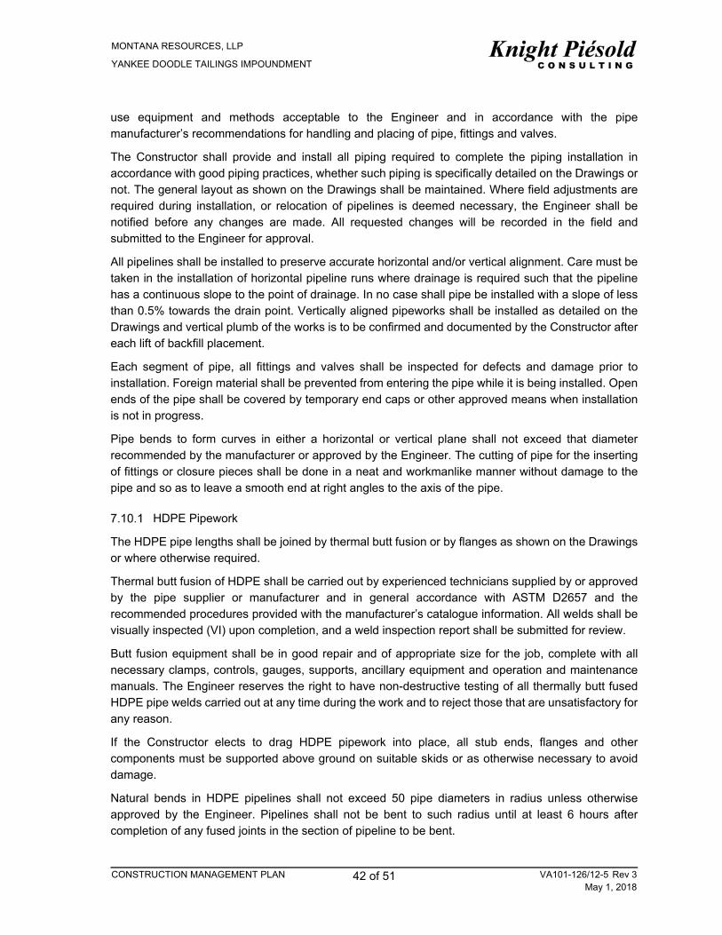
MONTANA RESOURCES, LLP
YANKEE DOODLE TAILINGS IMPOUNDMENT
CONSTRUCTION MANAGEMENT PLAN 42 of 51 VA101-126/12-5 Rev 3May 1, 2018
use equipment and methods acceptable to the Engineer and in accordance with the pipe manufacturer’s recommendations for handling and placing of pipe, fittings and valves.
The Constructor shall provide and install all piping required to complete the piping installation in accordance with good piping practices, whether such piping is specifically detailed on the Drawings or not. The general layout as shown on the Drawings shall be maintained. Where field adjustments are required during installation, or relocation of pipelines is deemed necessary, the Engineer shall be notified before any changes are made. All requested changes will be recorded in the field and submitted to the Engineer for approval.
All pipelines shall be installed to preserve accurate horizontal and/or vertical alignment. Care must be taken in the installation of horizontal pipeline runs where drainage is required such that the pipeline has a continuous slope to the point of drainage. In no case shall pipe be installed with a slope of less than 0.5% towards the drain point. Vertically aligned pipeworks shall be installed as detailed on the Drawings and vertical plumb of the works is to be confirmed and documented by the Constructor after each lift of backfill placement.
Each segment of pipe, all fittings and valves shall be inspected for defects and damage prior to installation. Foreign material shall be prevented from entering the pipe while it is being installed. Open ends of the pipe shall be covered by temporary end caps or other approved means when installation is not in progress.
Pipe bends to form curves in either a horizontal or vertical plane shall not exceed that diameter recommended by the manufacturer or approved by the Engineer. The cutting of pipe for the inserting of fittings or closure pieces shall be done in a neat and workmanlike manner without damage to the pipe and so as to leave a smooth end at right angles to the axis of the pipe.
HDPE Pipework
The HDPE pipe lengths shall be joined by thermal butt fusion or by flanges as shown on the Drawings or where otherwise required.
Thermal butt fusion of HDPE shall be carried out by experienced technicians supplied by or approved by the pipe supplier or manufacturer and in general accordance with ASTM D2657 and the recommended procedures provided with the manufacturer’s catalogue information. All welds shall be visually inspected (VI) upon completion, and a weld inspection report shall be submitted for review.
Butt fusion equipment shall be in good repair and of appropriate size for the job, complete with all necessary clamps, controls, gauges, supports, ancillary equipment and operation and maintenance manuals. The Engineer reserves the right to have non-destructive testing of all thermally butt fused HDPE pipe welds carried out at any time during the work and to reject those that are unsatisfactory for any reason.
If the Constructor elects to drag HDPE pipework into place, all stub ends, flanges and other components must be supported above ground on suitable skids or as otherwise necessary to avoid damage.
Natural bends in HDPE pipelines shall not exceed 50 pipe diameters in radius unless otherwise approved by the Engineer. Pipelines shall not be bent to such radius until at least 6 hours after completion of any fused joints in the section of pipeline to be bent.
MONTANA RESOURCES, LLP
YANKEE DOODLE TAILINGS IMPOUNDMENT
CONSTRUCTION MANAGEMENT PLAN 43 of 51 VA101-126/12-5 Rev 3May 1, 2018
The Constructor’s method for the placement of pipework will be reviewed by the Engineer prior to the start of installation. The Constructor shall develop methods such that the HDPE pipework is not damaged during installation or backfilling. The Constructor shall sequence the placement of the HDPE pipework to protect all pipework and other parts of the work from damage due to vehicle and equipment traffic. Construction tolerances for the HDPE pipeworks are presented in Table 7.2 and the Inspection and Test Plan is in Table 7.3.
A hydrostatic test for HDPE pipe shall be completed in accordance with ASTM International F 2164, Standard Practice for Field Leak Testing of Polyethylene (PE) Pressure Piping Systems using Hydrostatic Pressure unless otherwise agreed upon in writing by the Engineer. The test report shall be submitted to the Engineer for review and approval.
Steel Pipe
Installation of all steel pipe shall be in general accordance with AWWA M11 and the manufacturer’s instructions, with specific requirements as shown on the Drawings.
Pipe ends and fittings shall be cleaned thoroughly and be free of foreign matter prior to assembly and welding operations. Welding is to be performed to AWWA C206 and ASME BPVC Section VIII/1 as appropriate by qualified personnel. Welding processes are restricted to shielded metal arc (SMAW) or flux-cored arc (FCAW). Inspect edges of plates prepared for welding for signs of de-lamination, shearing cracks and other imperfections. Pieces showing signs of de-lamination must be rejected and immediately be removed from site. All welds shall be visually inspected upon completion, and a weld inspection report will be submitted for review.
Parts to be joined by welding must be fitted, aligned and retained in position during the welding operation by bars, jacks, clamps or other mechanical devices to the extent required such that the specified tolerances are met. Surfaces are to be free of irregularities, warpage, surface imperfections, slag and weld splatter.
Steel pipework is to be supported using concrete blocks and bracing as indicated in the Drawings.
The Constructor’s method for the placement of pipework will be reviewed by the Engineer prior to the start of installation. The Constructor shall develop methods such that the steel pipework is not damaged during installation or backfilling. The Constructor shall sequence the placement of the pipework to protect all pipework and other parts of the work from damage due to vehicle and equipment traffic. Construction tolerances for the steel pipeworks are presented in Table 7.2 and the Inspection and Test Plan is in Table 7.3.
For steel pipe, a hydrostatic test shall be completed with the pipe held at a hydrostatic pressure of 150% of the maximum operational static pressure for a period of at least one hour with no loss in pressure or visible leakage unless otherwise agreed upon in writing by the Engineer. The test report shall be submitted to the Engineer for review and approval.
Pipe Installation Quality Control Testing
Quality Control testing shall be carried out of the completed pipe installation to control that the constructed works meets the specifications and design intent and to identify potential non-conformances in the construction. The required testing frequencies are identified in Table 7.1.

MONTANA RESOURCES, LLP
YANKEE DOODLE TAILINGS IMPOUNDMENT
CONSTRUCTION MANAGEMENT PLAN 44 of 51 VA101-126/12-5 Rev 3May 1, 2018
Table 7.1 Pipe Installation Quality Control Testing
HDPE Pipe Welds Visual Inspection and Inspection Report for each field weld
HDPE Pipe Commissioning
Hydrostatic test in accordance with ASTM International F 2164, Standard Practice for Field Leak Testing of Polyethylene (PE) Pressure Piping Systems Using Hydrostatic Pressure.
One test for each pump well.
Steep Pipe Welds Visual Inspection and Inspection Report for each field weld
Steel Pipe Commissioning
Hydrostatic test at a hydrostatic pressure of 150% of the maximum operational static pressure for a period of at least one hour with no loss in pressure or visible leakage.
One test for each pump well.
7.11 CONSTRUCTION TOLERANCES
The Constructor shall construct the pipework to the lines and grades as shown on the Drawings, within the tolerances specified in Table 7.2:
Table 7.2 Pipework Construction Tolerances
Description Maximum Permissible Deviation
Line Grade Vertical Plumb
Steel Pipe 1 inches See Note 1 See Note 2
HDPE Pipe + 12 inches See Note 1 See Note 2
NOTES: 1. GRADE TOLERANCE IS LIMITED BY THE REQUIREMENT TO PROVIDE A MINIMUM 0.5 % SLOPE TOWARDS DRAIN
POINT ON ALL PIPING. 2. VERTICAL PLUMB OF THE PIPELINES ARE DEPENDENT ON THE APPLICATION AND MATERIAL SPECIFICATION.
DESIGN DRAWINGS WILL INDICATE THE CONSTRUCTION TOLERANCE AS REQUIRED.
7.12 AS-BUILT SURVEY
The Constructor shall provide the Engineer with copies of the as-built records of the pipeworks and appurtenances.
The Constructor shall present the as-built survey on as-built drawings in AutoCAD .dwg file format, complete with X, Y, and Z coordinates (northing, easting and elevation). The as-built drawing shall contain at a minimum:
Pipeline alignment and locations
Locations of valves, drains, pipe bends, etc., if applicable, and
Pipeline and sump locations, including inverts for each.

MONTANA RESOURCES, LLP
YANKEE DOODLE TAILINGS IMPOUNDMENT
CONSTRUCTION MANAGEMENT PLAN 45 of 51 VA101-126/12-5 Rev 3May 1, 2018
7.13 PIPEWORKS AND APPURTENANCES INSPECTION AND TEST PLAN
The Inspection and Test Plan detailed in Table 7.3 identifies the frequency and type of inspection, testing and documentation for the Pipeworks and Appurtenances procurement, installation and commissioning.
Table 7.3 Pipeworks and Appurtenances Inspection and Test Plan
Activity Inspection
Requirement Testing
Requirement Documentation
Requirement Hold Point
Requirement
Procurement Constructor inspection following receipt of product.
None Constructor to prepare submittal of manufacturer’s technical information and QC documentation.
Engineer to provide a response to the Constructor’s submittal.
Constructor to hold procurement of product until approval of submittal by the Engineer.
Constructors Installation Work Plan
None None Constructor to prepare submittal of the Constructers work Plan for pipeworks installation.
Engineer to provide a response to the Constructor’s submittal.
Constructor to hold installation of product until approval of submittal by the Engineer.
Pipework Installation and Commissioning
Daily Constructor Inspection.
Daily to monthly Engineer Inspection (see note 1).
QC testing by the Constructor as per Section 7.10.
Vertical plumb of relevant pipeworks is to be confirmed by the Constructor after each lift of backfill materials.
Constructor to prepare Submittal of QC documents.
Constructor to prepare as-built survey of installed pipeworks.
Engineer to review submittals and document in the QA report.
None
Pump Installation and Commissioning
Daily Constructor Inspection.
Daily to monthly Engineer Inspection (see note 1).
Commissioning and testing as per manufacturer’s instructions.
Constructor to prepare as-built survey of completed drain surface.
Engineer to prepare Inspection Report.
None
NOTES: 1. INSPECTIONS WILL BE COMPLETED BY THE ENGINEER ON A DAILY TO MONTHLY BASIS DEPENDING ON THE
LEVEL OF ON-GOING CONSTRUCTION.
▲R3

MONTANA RESOURCES, LLP
YANKEE DOODLE TAILINGS IMPOUNDMENT
CONSTRUCTION MANAGEMENT PLAN 46 of 51 VA101-126/12-5 Rev 3May 1, 2018
8 – GEOTECHNICAL INSTRUMENTATION
8.1 SUBMITTALS
The Constructor shall submit to the Engineer one copy of the manufacturer’s catalogues prior to procurement of the geotechnical instrumentation. Catalogues are to include detailed information on product specifications, performance data, dimensions and pressure ratings, storage and handling requirements, installation and splicing procedures, name and location of manufacturer’s representative, inspection and test plans, operation and maintenance manuals.
8.2 INSTALLATION PROCEDURES
All vibrating wire piezometers shall be calibrated according to the manufactures instructions prior to installation. The Constructor shall maintain records of the instrumentation calibration and provide to the Engineer for review.
The Constructor shall install vibrating wire piezometers at the locations shown on the Drawings. All piezometer leads shall be clearly marked with the equipment number, such that there will be no possible doubt as to the designation of each piece of equipment.
8.3 AS-BUILT SURVEY
The Constructor shall provide the Engineer with copies of the as-built survey data for the geotechnical instrumentation installed. In addition, the Constructor shall provide an as-built drawing in AutoCAD.dwg file format, complete with X, Y, and Z co-ordinates (northing, easting and elevation).
The as-built drawings shall contain as a minimum:
Location and elevations of piezometer tips, and lead alignments, and
Panel box locations.
8.4 GEOTECHNICAL INSTRUMENTATION INSPECTION AND TEST PLAN
The Inspection and Test Plan detailed in Table 8.1 identifies the frequency and type of inspection, testing and documentation for the Geotechnical Instrumentation procurement, installation and commissioning.

MONTANA RESOURCES, LLP
YANKEE DOODLE TAILINGS IMPOUNDMENT
CONSTRUCTION MANAGEMENT PLAN 47 of 51 VA101-126/12-5 Rev 3May 1, 2018
Table 8.1 Geotechnical Instrumentation Inspection and Test Plan
Activity Inspection
Requirement Testing
Requirement Documentation
Requirement Hold Point
requirement
Procurement Constructor inspection following receipt of product.
None Constructor to prepare submittal of manufacturer’s technical information and QC documentation.
Engineer to provide a response to the Constructor’s submittal.
Constructor to hold procurement of product until approval of submittal by the Engineer.
Pre-Installation Calibration
None Constructor to complete pre-installation calibration of the geotechnical instrumentation.
Constructor to prepare submittal of the calibration documentation.
Engineer to provide a response to the Constructor’s submittal.
None
Instrumentation Installation and Commissioning
Daily Constructor Inspection.
Ad-hoc Engineer Inspection.
Commissioning Testing as per the manufacturer’s instructions.
Constructor to prepare as-built survey of installed instrumentation.
Engineer inspection report.
None

MONTANA RESOURCES, LLP
YANKEE DOODLE TAILINGS IMPOUNDMENT
CONSTRUCTION MANAGEMENT PLAN 48 of 51 VA101-126/12-5 Rev 3May 1, 2018
9 – SITE RECLAMATION
9.1 GENERAL
Site reclamation is to be undertaken as per reclamation plans and objectives as agreed with the DEQ. Frequency and documentation of testing and inspections are to be met as per the reclamation requirements. It is understood that progressive embankment reclamation and re-vegetation will be completed concurrently with the construction when and where possible.

MONTANA RESOURCES, LLP
YANKEE DOODLE TAILINGS IMPOUNDMENT
CONSTRUCTION MANAGEMENT PLAN 49 of 51 VA101-126/12-5 Rev 3May 1, 2018
10 – REFERENCES
ACI 211.1 – Standard Practice for Selecting Proportions for Normal, Heavyweight, and Mass Concrete
ACI 305.1 - Specification for Hot Weather Concreting
ACI 306.1 - Guide to Cold Weather Concreting
ACI 308.1 - Specification for Curing of Concrete
ACI 309R - Guide for Consolidation of Concrete
ACI 315 - Details and Detailing of Concrete Reinforcement
ACI 347 – Guide to Formwork for Concrete
ANSI/ASME B16.1 – Cast Iron Pipe Flanges and Flanged Fittings Class 25, 125 And 250
ANSI/ASME B16.5 – Pipe Flanges and Flanged Fittings, NPS ½ through NPS24
ANSI/ASME B16.21 – Non-metallic Gaskets for Pipe Flanges
ANSI/ASME B16.47 – Large Diameter Steel Flanges: NPS 26 Through NPS 60
ASTM A126 – Standard Specification for Gray Iron Castings for Valves, Flanges, and Pipe Fittings
ASTM A312 – Standard Specification for Seamless, Welded, and Heavily Cold Worked Austenitic Stainless Steel Pipes
ASTM A325 – Standard Specification for Structural Bolts, Steel, Heat Treated, 120/105 ksi Minimum Tensile Strength
ASTM A536 – Standard Specifications for Ductile Iron Castings
ASTM A563M – Standard Specification for Carbon and Alloy Steel Nuts
ASTM A615 – Standard Specification for Deformed and Plain Carbon-Steel Bars for Concrete Reinforcement
ASTM C117 – Standard Test Method for Materials fine than 75mm (No. 200) Sieve in Mineral Aggregates by Washing
ASTM C136 – Standard Test Method for Sieve Analysis of Fine and Coarse Aggregates
ASTM D422 – Standard Test Method for Particle-Size Analysis of Soils
ASTM D854 – Standard Test Method for Specific Gravity of Soil Solids by Water Pycnometer
ASTM D2216 – Standard Test Methods for Laboratory Determination of Water (Moisture) Content of Soil and Rock by Mass
ASTM D2513 – Standard Specification for Polyethylene (PE) Gas Pressure Pipe, Tubing, and Fittings
ASTM D2657 – Standard Practice for Heat Fusion Joining of Polyolefin Pipe and Fittings
ASTM D3035 – Standard Specification for Polyethylene (PE) Plastic Pipe (DR-PR) Based on Controlled Outside Diameter

MONTANA RESOURCES, LLP
YANKEE DOODLE TAILINGS IMPOUNDMENT
CONSTRUCTION MANAGEMENT PLAN 50 of 51 VA101-126/12-5 Rev 3May 1, 2018
ASTM D3350 – Standard Specification for Polyethylene Plastics Pipe and Fittings Materials
ASTM D3776 – Standard Test Methods for Mass Per Unit Area (Weight) of Fabric
ASTM D4533 – Standard Test Method for Trapezoid Tearing Strength of Geotextiles
ASTM D4632 – Standard Test Method for Grab Breaking Load and Elongation of Geotextiles
ASTM D4751 – Standard Test Methods for Determining Apparent Opening Size of a Geotextile
ASTM D4873 – Standard Guide for Identification, Storage, and Handling of Geosynthetic Rolls and Samples
ASTM D6241 – Standard Test Method for Static Puncture Strength of Geotextiles and Geotextile-Related Products using a 50-mm Probe
ASTM F436 – Standard Specification for Hardened Steel Washers
ASTM F714 – Standard Specification for Polyethylene (PE) Plastic Pipe (DR-PR) Based on Outside Diameter
ASTM F2164 – Standard Practice for Field Leak Testing of Polyethylene (PE) and Crosslinked Polyethylene (PEX) Pressure Piping Systems Using Hydrostatic Pressure
AWWA C200 – Steel and Water Pipe 6 inches and Larger
AWWA C206 – Field Welding of Steel Water Pipe
AWWA C512 – Air Release, Air/Vacuum, and Combination Air Valves for Waterworks Service
AWWA M11 – Steel Water Pipe – A Guide for Design and Installation
ISRM, 2007-2014, R. Ulusay (ed.), The ISRM Suggested Methods for Rock Characterization, Testing and Monitoring: 2007–2014, DOI: 10.1007/978-3-319-07713-0
Knight Piésold Ltd. (KP, 2016). Yankee Doodle Tailings Impoundment, West Embankment Drain Design Report (KP Reference No. VA101-126/13-3 Rev 0), Vancouver, British Columbia.
Montana Code Annotated (MCA), 2015. Title 82: Minerals, Oil, and Gas, Chapter 4: Reclamation, Part 3: Metal Mine Reclamation. Accessed: November 2015. Available at: http://leg.mt.gov/bills/mca_toc/82_4_3.htm
Montana Resources, LLP (MR, 2016). Yankee Doodle Tailings Impoundment, Tailings Operations, Maintenance and Surveillance (TOMS) Manual (KP Reference No. VA101-126/13-1 Rev 0), April 20, 2016.


MONTANA RESOURCES, LLP
YANKEE DOODLE TAILINGS IMPOUNDMENT
CONSTRUCTION MANAGEMENT PLAN VA101-126/12-5 Rev 3May 1, 2018
APPENDIX A
QA AND QC REPORTING DOCUMENTATION TEMPLATES
Appendix A1 Construction Inspection Report Template Appendix A2 Daily Site Report Template Appendix A3 Subgrade Inspection Report Template Appendix A4 Monthly Quality Report Template Appendix A5 Request for Information Template Appendix A6 Design Change Request Template

MONTANA RESOURCES, LLP
YANKEE DOODLE TAILINGS IMPOUNDMENT
CONSTRUCTION MANAGEMENT PLAN VA101-126/12-5 Rev 3May 1, 2018
APPENDIX A1
CONSTRUCTION INSPECTION REPORT TEMPLATE
(Pages A1-1 to A1-2)

YANKEE DOODLE TAILINGS IMPOUNDMENT CONSTRUCTION QUALITY ASSURANCE
Month DD to DD, YYYY SITE INSPECTION REPORT
Month, DD, YYYY Knight Piésold C O N S U L T I N G
www.knightpiesold.com
1
CLIENT: MONTANA RESOURCES, LLP PROJECT NO.:
TO: FILE NO.:
CC: REF. NO.:
FROM: Inspectors Name PAGES:
1 – DESCRIPTION OF SITE INSPECTION
Between Month XX to XX, YYYR, MR completed…..
1.1 SITE INSPECTION STAFF
Site Inspectors: Name, Company
1.2 DESCRIPTION OF CONSTRUCTION
Example: The following details regarding the Test Fill are provided:
• Fill Placement (Detail the quality of the material, the loose lift thickness, the consistency of the material etc.)
• Survey (Detail the survey technique used and the regularity and compliance with the KP memo)
• Compaction (provide any details regarding compaction). i.e. MR trialled the rental HAMM 3520 HT Smooth
Drum vibratory compactor. The complete the required number of passes.. they had trouble with xxx, such
and such worked well…
1.3 DESCRIPTION OF TESTING RESULTS
Example: The results of the test fill as recorded by MR are provided in the data sheets provided attached to this
report. A summary of the results is provided below.
Graph of displacement delta versus passes for each lift. As can be seen from the graph, the material is shown
to meet 80% of the average settlement after 6 passes
1.4 METHOD SPECIFICATION VERIFICATION
Example: The finalized method specification is as follows:
Zone D1 – 6 passes of the HAMM 3520T Smooth Drum Vibratory Roller
1.5 ADDITIONAL INFORMATION (EXAMPLE: TEST PIT DENSITY TEST)
Example: MR complete a Test Pit in the compacted Test Fill in accordance with KP memorandum VA15-03227.
Details, details, details.
The in-situ density is as follows:
A1-1 of 2

YANKEE DOODLE TAILINGS IMPOUNDMENT CONSTRUCTION QUALITY ASSURANCE
Month DD to DD, YYYY SITE INSPECTION REPORT
Month, DD, YYYY Knight Piésold C O N S U L T I N G
www.knightpiesold.com
2
2 – PHOTO LOG
Photo 1 Description
Photo 2 Description
A1-2 of 2

MONTANA RESOURCES, LLP
YANKEE DOODLE TAILINGS IMPOUNDMENT
CONSTRUCTION MANAGEMENT PLAN VA101-126/12-5 Rev 3May 1, 2018
APPENDIX A2
DAILY SITE REPORT TEMPLATE
(Pages A2-1 to A2-3)

YANKEE DOODLE TAILINGS IMPOUNDMENT CONSTRUCTION QUALITY ASSURANCE
Month, DD, YYYY DAILY PROGRESS REPORT
Month, DD, YYYY Knight Piésold C O N S U L T I N G
www.knightpiesold.com
1
CLIENT: MONTANA RESOURCES, LLP PROJECT NO.:
TO: FILE NO.:
CC: REF. NO.:
FROM: Inspectors Name PAGES:
1 – GENERAL
1.1 SITE INSPECTION STAFF
Site Inspectors: Name, Company
1.2 HEALTH AND SAFETY
• Description of any relevant health and safety
1.3 MEETINGS AND CORRESPONDENCE
• Description of any meetings or relevant correspondence
1.4 WEATHER
• Description of weather
2 – CONSTRUCTION ACTIVITIES
2.1 WEST EMBANKMENT
• Description of works
2.2 WEST EMBANKMENT DRAIN
• Description of works
2.3 EAST-WEST EMBANKMENT
• Description of works
2.4 NORTH-SOUTH EMBANKMENT
• Description of works
A2-1 of 3

YANKEE DOODLE TAILINGS IMPOUNDMENT CONSTRUCTION QUALITY ASSURANCE
Month, DD, YYYY DAILY PROGRESS REPORT
Month, DD, YYYY Knight Piésold C O N S U L T I N G
www.knightpiesold.com
2
Photo 1 Description
Photo 2 Description
A2-2 of 3

YANKEE DOODLE TAILINGS IMPOUNDMENT CONSTRUCTION QUALITY ASSURANCE
Month, DD, YYYY DAILY PROGRESS REPORT
Month, DD, YYYY Knight Piésold C O N S U L T I N G
www.knightpiesold.com
3
3 – CONSTRUCTION QUALITY ASSURANCE
3.1 QUALITY ASSURANCE
• Summary of all QA Testing and Documentation
3.2 QUALITY CONTROL
• Summary of all QC Testing and Documentation
4 – ENGINEERING ITEMS
• Summary of other relevant or outstanding engineering items.
Photo 3 Description
A2-3 of 3

MONTANA RESOURCES, LLP
YANKEE DOODLE TAILINGS IMPOUNDMENT
CONSTRUCTION MANAGEMENT PLAN VA101-126/12-5 Rev 3May 1, 2018
APPENDIX A3
SUBGRADE INSPECTION REPORT TEMPLATE
(Pages A3-1 to A3-2)

YANKEE DOODLE TAILINGS IMPOUNDMENT CONSTRUCTION QUALITY ASSURANCE
Month, DD, YYYY SUB-GRADE INSPECTION RECORD
Month, DD, YYYY Knight Piésold C O N S U L T I N G
www.knightpiesold.com
1
CLIENT: MONTANA RESOURCES, LLP PROJECT NO.:
TO: FILE NO.: SIR #XX
CC: REF. NO.:
FROM: Inspectors Name PAGES:
1 – GENERAL
1.1 SITE INSPECTION STAFF
Sub-grade Inspectors: Name, Company
1.2 WEATHER
Description of weather conditions during the inspection
2 – LOCATION
Location of sub-grade inspection
3 – SUB-GRADE DESCRIPTION
Description of materials, conditions etc
4 – APPROVAL / RECOMMENDATIONS FOR APPROVAL
Notes
A3 1 of 2

YANKEE DOODLE TAILINGS IMPOUNDMENT CONSTRUCTION QUALITY ASSURANCE
Month, DD, YYYY SUB-GRADE INSPECTION RECORD
Month, DD, YYYY Knight Piésold C O N S U L T I N G
www.knightpiesold.com
2
5 – PHOTO LOG
Photo 1 Description
Photo 2 Description
A3 2 of 2

MONTANA RESOURCES, LLP
YANKEE DOODLE TAILINGS IMPOUNDMENT
CONSTRUCTION MANAGEMENT PLAN VA101-126/12-5 Rev 3May 1, 2018
APPENDIX A4
MONTHLY QUALITY REPORT TEMPLATE
(Pages A4-1 to A4-32)

MONTH YEAR 1
YANKEE DOODLE TAILINGS IMPOUNDMENT
MONTHLY QUALITY CONTROL REPORT
Monthly Quality Report
TO: Ken Brouwer, Dan Fontaine REPORT MONTH: MONTH, YYYY
CC: Mark Thompson, Josh Shutey, Roanna Stewart, Jason Gillespie, Jesse Collison
DATE ISSUED:
FROM: Amanda Griffith CONSTRUCTOR: Montana Resources & Mungas Co. Inc.
PAGES:
1 – GENERAL
1.1 SITE INSPECTION STAFF
List all appropriate staff for the reporting month. Example:
The following Site Staff were on site this month:
Montana Resources, LLP (MR):
Josh Shutey, Manager Engineering and Geology
Amanda Griffith, Geologist
Mungas Company, Inc. (Mungas):
Jeff LeFever, Construction Manager
Knight Piésold Ltd (KP):
Jason Gillespie, Project Engineer
Jesse Collison, Staff Engineer
1.2 WEATHER
Description of weather during reporting month. Example:
During the month of November 2016, the weather was mostly cloudy with periods of rain and light snow. Day time
temperatures averaged from 24 to 43 degrees Fahrenheit. There was one cancelled day of operation due to
weather, and two days off for the Thanksgiving Holiday. Expected normal weather with mostly cloudy skies, a few
clear days, and numerous days of light rain turning to snow.
1.3 HEALTH AND SAFETY
Description and summary of health and safety items addressed during reporting month. Example:
MR Health and Safety meetings are held every Monday and follow MSHA predefined weekly topics for open pit
miners. Mungas completed daily pre-operations inspections critical during cold weather conditions which occur
during initial morning start up and again during refuelling; including inspections of lights, fluid levels, brakes,
material buildup and removal, mechanical inspections and clearances, safety systems, fire extinguishers, steering
components, pin and pin keepers, windows, wipers etc. Use of appropriate tools and safety equipment for the job.
A Weekly Best Practices Meeting is held where operator responsibilities are discussed and any issues can be
addressed. Safety practices such as equipment operations on muddy and/or icy roads and other changing
conditions of roadways, grades, clearances, maintenance of berms, inspections of dump point edges, visibility and
traffic are discussed. The following Health and Safety concerns were ongoing throughout the month:
Securing, blocking and/or chocking equipment: sounding horn for safety
Lock-out/Tag-out processes
Wearing seat belts and using other personal protection equipment
Number and types of fatalities in the Metal and Non-Metal Mining industry
Slips and falls, three points of contact
Weekly Toolbox Tips
A4 1 of 32

MONTH YEAR 2
YANKEE DOODLE TAILINGS IMPOUNDMENT
MONTHLY QUALITY CONTROL REPORT
Monthly Quality Report
1.4 MEETINGS AND CORRESPONDENCE
The following is a list of meetings and correspondence from during the reporting month:
The weekly construction meetings were held between KP and MR.
Daily Progress Reports were issued by Mungas.
Weekly site visits were performed with MR and Mungas.
Site meetings with Knight Piésold representatives.
2 – ENGINEERING ITEMS
KP responds, as required, to engineering related items that developed during the course of the construction
program. Include description of any engineering related items in the format shown below.
2.1 DESIGN CHANGE REQUESTS
Detail any DCRs
2.2 REQUEST FOR INFORMATION
Detail any RFIs
2.3 FIELD INSTRUCTIONS
Detail any FIs
2.4 NON-CONFORMANCE REPORTS
Detail and NCRs
3 – CONSTRUCTION ACTIVITIES
3.1 MONTANA RESOURCES ACTIVITIES
Provide a summary of the activities completed by Montana Resources around the YDTI.
3.1.1 Stockpile Development
Provide a summary of the stockpile materials development and locations of stockpiles. Example:
Materials were hauled to Rocky Knob Drain Rock Stockpile and Filter Material Stockpile. Materials were sourced
from both the Pipestone Quarry and the Continental Pit. Appendix A and B will further describe the materials and
present the quality system results.
A summary of the materials stockpiled during MONTH is presented in the table below. Detailed quantities are reported in Appendix A.
Table 1 Total Stockpiled Material Summary
MATERIAL
MONTHLY VOLUME
(yd3)
CUMULATIVE TO DATE VOLUME
(yd3)
TOTAL REQUIRED VOLUME
(yd3)
Zone U - Rockfill
Zone UA – Protective Cap
Zone D1 – Rockfill
Zone 2A – Filter Material
Zone 2B – Transition Material & Zone N – Instrumentation Bedding
A4 2 of 32

MONTH YEAR 3
YANKEE DOODLE TAILINGS IMPOUNDMENT
MONTHLY QUALITY CONTROL REPORT
Monthly Quality Report
Zone 2C – Drain Rock
Zone 3A – Drain Rock
Figure 1 Zone D1, 2A, 2B, and 3A Stockpiling
3.1.2 Zone U and Zone D1 Placement
Table 2 Total Material Placement Summary to Date – Montana Resources
MATERIAL
MONTHLY VOLUME
(yd3)
CUMULATIVE TO DATE VOLUME
(yd3)
TOTAL REQUIRED VOLUME
(yd3)
Zone U - Rockfill
Zone D1 – Rockfill
3.2 MUNGAS CONSTRUCTION ACTIVITIES
A general summary Mungas construction activities around the YDTI is to be presented below. Example:
Mungas construction works included:
Extraction Basin 1 dewatering and foundation preparation and grubbing
WED construction, foundation preparation, and KP inspections, Station 0+00 thru 16+40
WED geotextile, 2A, 2B and 3A fill placement and KP inspections, Station 0+00 thru 16+40
WED Foundation Excavation, Station 14+00 thru 40+00
South Pond Basin D1 Zone placement
Drain Pod 1, initiated UA Protective Cap placement
Site Preparation
Extraction Basin 1 dewatering and foundation preparation and grubbing
WED construction, foundation preparation, installation and KP inspections, Station 0+00 thru 16+40
WED Foundation Excavation, Station 14+00 thru 40+00
0
50,000
100,000
150,000
200,000
250,000
300,000
350,000
12/31/2015 2/19/2016 4/9/2016 5/29/2016 7/18/2016 9/6/2016 10/26/2016 12/15/2016 2/3/2017
Sto
ckp
iled
Cu
yds
Date
Planned and Actual Stockpiled Cuyds by Date
D1 Planned
2A Planned
2B Planned
3A Planned
D1 Actual
2A Actual
2B Actual
3A Actual
A4 3 of 32

MONTH YEAR 4
YANKEE DOODLE TAILINGS IMPOUNDMENT
MONTHLY QUALITY CONTROL REPORT
Monthly Quality Report
Material Placement and Compaction Summary
South Pond Basin D1 Zone placement
Drain Pod 1, initiated UA Protective Cap placement
The table below summarizes all materials placed and compacted by Mungas operations during MONTH. Figure 2
presents the planned and actual placed material volumes to date. Record testing and results for the placed and
compacted materials are presented in Appendix C.
Table 3 Total Material Placement Summary to Date – Mungas
MATERIAL
MONTHLY VOLUME
(yd3)
CUMULATIVE TO DATE VOLUME
(yd3)
TOTAL REQUIRED VOLUME
(yd3)
Zone U - Rockfill
Zone UA – Protective Cap
Zone D1 – Rockfill
Zone N - Instrumentation
Zone 2A – Filter Material
Zone 2B – Transition Material
Zone 3A – Drain Rock
Figure 2 Material Placement Summary
4 – CONSTRUCTION SCHEDULE
Provide an update to the construction schedule for the coming months. Include details along the WED and YDTI Embankments. Example:
The proposed construction schedule was provided by Mungas during the construction meeting and a rolling schedule is ongoing. Start and finish dates will be updated as the work progresses.
0
50,000
100,000
150,000
200,000
250,000
300,000
350,000
12/31/2015 2/19/2016 4/9/2016 5/29/2016 7/18/2016 9/6/2016 10/26/2016 12/15/2016
Pla
ced
Cu
yds
Date
Planned and Actual Placed Cuyds by Date
D1 Planned
2A Planned
2B Planned
3A Planned
D1 Actual
2A Actual
2B Actual
3A Actual
A4 4 of 32
MONTH YEAR 5
YANKEE DOODLE TAILINGS IMPOUNDMENT
MONTHLY QUALITY CONTROL REPORT
Monthly Quality Report
Bulk Earthworks – March 2016 to February 2017
West Embankment Drain – Stage 1 - September 2016 to May 2017
Extraction Basin Pipeworks and Appurtenances – September 2016 to December 2016
o Drain Pods – April 2016 to August 2016
o Extraction Basin – September 2016 to November 2016
A4 5 of 32

MONTH YEAR 6
YANKEE DOODLE TAILINGS IMPOUNDMENT
MONTHLY QUALITY CONTROL REPORT
Monthly Quality Report
5 – LIST OF TABLES AND FIGURES
Tables
Table 1 Total Stockpiled Material Summary ............................................................................................................ 2 Table 2 Total Material Placement Summary to Date – Montana Resources .......................................................... 3 Table 3 Total Material Placement Summary to Date – Mungas .............................................................................. 4 Table 4 November Control Testing Summary – Continental Pit Materials .............................................................. 8 Table 5 November Control Testing Summary – Pipestone Quarry Materials ......................................................... 8 Table 6 Control Samples - Continental Materials to Date ..................................................................................... 11 Table 7 Control Samples - Pipestone Material to Date ......................................................................................... 12 Table 8 ABA Testing Summary to Date ................................................................................................................ 15 Table 9 Monthly Control Testing Summary –Stockpiled Materials ........................................................................ 17 Table 10 Stockpiled Materials Summary to Date .................................................................................................. 18 Table 11 Monthly Record Testing Summary – Placed and Compacted Materials ................................................ 23 Table 12 Record Testing to Date Summary .......................................................................................................... 24 Table 13 Moisture Content Summary to Date ....................................................................................................... 27
Figures
Figure 1 Zone D1, 2A, 2B, and 3A Stockpiling .................................................................................................. 3 Figure 2 Material Placement Summary ............................................................................................................. 4 Figure 4 Zone UA Control (Source) Particle Distribution November Results. Split-Net results only. ................ 9 Figure 5 Zone 2A Control (Source) Particle Distribution November Results ..................................................... 9 Figure 6 Zone 3C Control (Source) Particle Distribution November Results ................................................. 10 Figure 7 Zone 3A Control (Source) Particle Distribution November Results ................................................... 10 Figure 8 Zone 3A Drain Rock material stockpiled in November. ..................................................................... 11 Figure 9 Zone D1 Control (Source) Particle Size Distribution Tests to Date ................................................... 12 Figure 10 Zone 2A Control (Source) Particle Size Distribution Tests to Date ................................................... 13 Figure 11 Zone 2B Control (Source) Particle Size Distribution Tests to Date ................................................... 13 Figure 12 Zone 2C Control (Source) Particle Size Distribution Tests to Date ................................................... 14 Figure 13 Zone 3A Control (Source) Particle Size Distribution Tests to Date ................................................... 14 Figure 13 Pipestone Quarry Stockpile Locations (2A – Green; 2B – Yellow; 3A – Orange) ............................. 17 Figure 15 Zone 3A Control (Stockpile) Particle Distribution November Results. (1 pending sample) .............. 18 Figure 16 Zone D1 Control (Stockpiled) Particle Size Distribution to Date ....................................................... 19 Figure 17 Zone 2A Control (Stockpiled) Particle Size Distribution to Date........................................................ 20 Figure 18 Zone 2B Control (Stockpiled) Particle Size Distribution to Date........................................................ 20 Figure 19 Zone 3A Record Particle Distribution Month Results. ....................................................................... 24 Figure 20 Zone D1 Record Particle Distribution Results to Date ...................................................................... 25 Figure 21 Zone 2A Record Particle Distribution Results to Date ....................................................................... 26 Figure 22 Zone 2B Record Particle Distribution Results to Date ....................................................................... 26
A4 6 of 32

MONTH YEAR 7
YANKEE DOODLE TAILINGS IMPOUNDMENT
MONTHLY QUALITY CONTROL REPORT
Monthly Quality Report
CONTROL (MATERIAL SOURCE) TESTING
A4 7 of 32

MONTH YEAR 8
YANKEE DOODLE TAILINGS IMPOUNDMENT
MONTHLY QUALITY CONTROL REPORT
Monthly Quality Report
6 – CONTROL TESTING - SOURCE MATERIALS SUMMARY
Summary of the Control Testing completed on the SOURCE materials. Example:
Materials are sourced for use around the YDTI from the Pipestone Quarry and the Continental Pit. A summary of the reporting months stockpiled materials is presented in this section.
6.1 MONTHLY QC SUMMARY
As part of the Quality System outlined in the Construction Management Plan (CMP), Control Testing was
completed on the source materials. Required and completed testing on the pit and Pipestone materials is
summarized in the tables below.
Table 4 November Control Testing Summary – Continental Pit Materials
CONTROL TEST
FREQUENCY CUMULATIVE
VOLUME TO
DATE
NOVEMBER MATERIAL
STOCKPILED
Material Type
C1 C2
VOLUME
C1 C2
1 PER 1 PER Completed /
Required
Completed
/ Required
Zone F - Upstream Earthfill 20,000 - -
Zone U - Upstream Rockfill 400,000 400,000
Zone UA - Protective Cap 4,000 4,000
Zone D1 - Downstream Rockfill 40,000 40,000
Table 5 November Control Testing Summary – Pipestone Quarry Materials
CONTROL TEST
FREQUENCY CUMULATIVE
VOLUME TO
DATE
NOVEMBER MATERIAL
STOCKPILED
Material Type
C1 C2
VOLUME
C1 C2
1 PER 1 PER Completed /
Required
Completed
/ Required
Zone N - Instrumentation Bedding 2,000 - -
Zone 2A - Filter Material 2,000 - -
Zone 2B - Transition Material 2,000 - -
Zone 2C - Drain Rock 1,500 - -
Zone 3A - Drain Rock 4,000 - -
TEST METHODS
C1 – Particle Size Distribution using Split-Net Image Analyses and testing to ASTM D422 or C136/C117.
C2 – Acid Base Accounting (ABA) Acid Production Potential (AP) and Neutralization Potential (NP) Testing.
NOTES:
1. TESTING FREQUENCY IS “1 PER” THE NUMBER OF CUBIC YARDS OF MATERIAL INDICATED IN THE TABLE.
2. TESTING FREQUENCY AS OUTLINED IN THE CONSTRUCTION MANAGEMENT PLAN REV 2.
6.1.1 Particle Size Distribution Results
The following are results that were returned in MONTH. Include plots for all materials collected and returned for
the reporting month.
A4 8 of 32

MONTH YEAR 9
YANKEE DOODLE TAILINGS IMPOUNDMENT
MONTHLY QUALITY CONTROL REPORT
Monthly Quality Report
Figure 3 Zone UA Control (Source) Particle Distribution November Results. Split-Net results only.
Figure 4 Zone 2A Control (Source) Particle Distribution November Results
COARSE FINE COARSE MEDIUM FINE COARSE MEDIUM FINEBOULDERS COBBLES
GRAVEL SAND SILT
CLAY
0
10
20
30
40
50
60
70
80
90
100
0.0010.010.1110100100010000
Pe
rce
nt
Pas
sin
g b
y W
eig
ht
Grain Size (mm)
UA-C2-161128
SIEVE OPENING IN INCHES US STANDARD SIEVE SIZES24" 12" 6" 4" 3" 2" 1" 3/4" 1/2" 3/8" 1/4" #4 #10 #16 #20 #40 #50 #100 #200 #400
Quality Control Zone UA Protective Cap Material Results returned in November 2016
COARSE FINE COARSE MEDIUM FINE COARSE MEDIUM FINE CLAYBOULDERS COBBLES
GRAVEL SAND SILT
0
10
20
30
40
50
60
70
80
90
100
0.0010.010.1110100100010000
Pe
rce
nt
Pas
sin
g b
y W
eig
ht
Grain Size (mm)
Quality Control Zone 2A Filter Results returned in November 2016
SIEVE OPENING IN INCHES US STANDARD SIEVE SIZES24" 12" 6" 4" 3" 2" 1" 3/4" 1/2" 3/8" 1/4" #4 #10 #16 #20 #40 #50 #100 #200 #400
95% Percentile5% Percentile
Average
December 2015 samples -Green
Composite samples Blue
August 2016 samples -Orange
September 2016 samples -Gray
October 2016 samples -Gold
A4 9 of 32

MONTH YEAR 10
YANKEE DOODLE TAILINGS IMPOUNDMENT
MONTHLY QUALITY CONTROL REPORT
Monthly Quality Report
Figure 5 Zone 3C Control (Source) Particle Distribution November Results
Figure 6 Zone 3A Control (Source) Particle Distribution November Results
COARSE FINE COARSE MEDIUM FINE COARSE MEDIUM FINE CLAYBOULDERS COBBLES
GRAVEL SAND SILT
0
10
20
30
40
50
60
70
80
90
100
0.0010.010.1110100100010000
Pe
rce
nt
Pas
sin
g b
y W
eig
ht
Grain Size (mm)
Quality Control Zone 2C Material Stockpiled in November 2016
SIEVE OPENING IN INCHES US STANDARD SIEVE SIZES24" 12" 6" 4" 3" 2" 1" 3/4" 1/2" 3/8" 1/4" #4 #10 #16 #20 #40 #50 #100 #200 #400
COARSE FINE COARSE MEDIUM FINE COARSE MEDIUM FINE CLAYBOULDERS COBBLES
GRAVEL SAND SILT
0
10
20
30
40
50
60
70
80
90
100
0.0010.010.1110100100010000
Pe
rce
nt
Pas
sin
g b
y W
eig
ht
Grain Size (mm)
SIEVE OPENING IN INCHES US STANDARD SIEVE SIZES24" 12" 6" 4" 3" 2" 1" 3/4" 1/2" 3/8" 1/4" #4 #10 #16 #20 #40 #50 #100 #200 #400
95% Percentile
5% Percentile
Average
Quality Control Zone 3A Drain Rock Material Stockpiled through November 2016
A4 10 of 32

MONTH YEAR 11
YANKEE DOODLE TAILINGS IMPOUNDMENT
MONTHLY QUALITY CONTROL REPORT
Monthly Quality Report
Figure 7 Zone 3A Drain Rock material stockpiled in November.
6.1.2 Acid Base Accounting Testing
List ABA samples taken in MONTH.
6.1.3 Additional Testing
List any additional testing performed in MONTH.
6.2 TOTAL SOURCE CONTROL TESTING TO DATE
6.2.1 Source Control (Source) Testing Summary
Table 6 Control Samples - Continental Materials to Date
CONTROL TEST
FREQUENCY CUMULATIVE
VOLUME TO
DATE
TO DATE MATERIAL
STOCKPILED
Material Type
C1 C2 C1 C2
1 PER 1 PER Completed /
Required
Completed /
Required
Zone F - Upstream Earthfill 20,000 - -
Zone U - Upstream Rockfill 400,000 400,000
Zone UA - Protective Cap 4,000 4,000
Zone D1 - Downstream Rockfill 40,000 40,000
A4 11 of 32

MONTH YEAR 12
YANKEE DOODLE TAILINGS IMPOUNDMENT
MONTHLY QUALITY CONTROL REPORT
Monthly Quality Report
Table 7 Control Samples - Pipestone Material to Date
CONTROL TEST
FREQUENCY CUMULATIVE
VOLUME TO
DATE
TO DATE MATERIAL
STOCKPILED
Material Type
C1 C2 C1 C2
1 PER 1 PER Completed /
Required
Completed /
Required
Zone N – Instrumentation Bedding 2,000 - -
Zone 2A – Filter Material 2,000 - -
Zone 2B – Transition Material 2,000 - -
Zone 2C – Drain Rock 1,500 - -
Zone 3A – Drain Rock 4,000 - -
6.2.2 Particle Size Distribution Results
The following are the particle size distribution results completed to date from the source materials control testing.
Include plots for all materials collected and returned TO DATE.
Figure 8 Zone D1 Control (Source) Particle Size Distribution Tests to Date
COARSE FINE COARSE MEDIUM FINE COARSE MEDIUM FINEBOULDERS COBBLES
GRAVEL SAND SILT
CLAY
0
10
20
30
40
50
60
70
80
90
100
0.0010.010.1110100100010000
Pe
rce
nt
Pas
sin
g b
y W
eig
ht
Grain Size (mm)
D1-C2-160122D1-C2-160203D1-C2-160217D1-C2-160503D1-C2-160602
SIEVE OPENING IN INCHES US STANDARD SIEVE SIZES24" 12" 6" 4" 3" 2" 1" 3/4" 1/2" 3/8" 1/4" #4 #10 #16 #20 #40 #50 #100 #200 #400
Quality Control Zone D1 Downstream Rockfill Returned through November 2016
A4 12 of 32

MONTH YEAR 13
YANKEE DOODLE TAILINGS IMPOUNDMENT
MONTHLY QUALITY CONTROL REPORT
Monthly Quality Report
Figure 9 Zone 2A Control (Source) Particle Size Distribution Tests to Date
Figure 10 Zone 2B Control (Source) Particle Size Distribution Tests to Date
COARSE FINE COARSE MEDIUM FINE COARSE MEDIUM FINE CLAYBOULDERS COBBLES
GRAVEL SAND SILT
0
10
20
30
40
50
60
70
80
90
100
0.0010.010.1110100100010000
Pe
rce
nt
Pas
sin
g b
y W
eig
ht
Grain Size (mm)
Quality Control Zone 2A Filter Results returned through November 2016
SIEVE OPENING IN INCHES US STANDARD SIEVE SIZES24" 12" 6" 4" 3" 2" 1" 3/4" 1/2" 3/8" 1/4" #4 #10 #16 #20 #40 #50 #100 #200 #400
95% Percentile5% Percentile
Average
December 2015 samples -Green
Composite samples Blue
August 2016 samples -Orange
September 2016 samples -Gray
October 2016 samples -Gold
COARSE FINE COARSE MEDIUM FINE COARSE MEDIUM FINEBOULDERS COBBLES
GRAVEL SAND SILT
CLAY
0
10
20
30
40
50
60
70
80
90
100
0.0010.010.1110100100010000
Pe
rce
nt
Pas
sin
g b
y W
eig
ht
Grain Size (mm)
Quality Control Zone 2B Transition Material Results through November 2016
SIEVE OPENING IN INCHES US STANDARD SIEVE SIZES24" 12" 6" 4" 3" 2" 1" 3/4" 1/2" 3/8" 1/4" #4 #10 #16 #20 #40 #50 #100 #200 #400
95% Percentile
5% Percentile
Average
A4 13 of 32

MONTH YEAR 14
YANKEE DOODLE TAILINGS IMPOUNDMENT
MONTHLY QUALITY CONTROL REPORT
Monthly Quality Report
Figure 11 Zone 2C Control (Source) Particle Size Distribution Tests to Date
Figure 12 Zone 3A Control (Source) Particle Size Distribution Tests to Date
COARSE FINE COARSE MEDIUM FINE COARSE MEDIUM FINE CLAYBOULDERS COBBLES
GRAVEL SAND SILT
0
10
20
30
40
50
60
70
80
90
100
0.0010.010.1110100100010000
Pe
rce
nt
Pas
sin
g b
y W
eig
ht
Grain Size (mm)
Quality Control Zone 2C Material Stockpiled in November 2016
SIEVE OPENING IN INCHES US STANDARD SIEVE SIZES24" 12" 6" 4" 3" 2" 1" 3/4" 1/2" 3/8" 1/4" #4 #10 #16 #20 #40 #50 #100 #200 #400
COARSE FINE COARSE MEDIUM FINE COARSE MEDIUM FINE CLAYBOULDERS COBBLES
GRAVEL SAND SILT
0
10
20
30
40
50
60
70
80
90
100
0.0010.010.1110100100010000
Pe
rce
nt
Pas
sin
g b
y W
eig
ht
Grain Size (mm)
SIEVE OPENING IN INCHES US STANDARD SIEVE SIZES24" 12" 6" 4" 3" 2" 1" 3/4" 1/2" 3/8" 1/4" #4 #10 #16 #20 #40 #50 #100 #200 #400
95% Percentile
5% Percentile
Average
Quality Control Zone 3A Drain Rock Material Stockpiled through November 2016
January 2016 samples -Navy
February 2016 samples- Maroon
March 2016 samples -Green
May 2016 samples -Purple
June 2016 samples -Turquoise
July 2016 samples-Blue
August 2016 samples-Orange
September 2016 samples -Gray
October 2016 samples -Gold
November 2016 samples -Pink
A4 14 of 32

MONTH YEAR 15
YANKEE DOODLE TAILINGS IMPOUNDMENT
MONTHLY QUALITY CONTROL REPORT
Monthly Quality Report
6.2.3 Acid Base Accounting Testing
Include all ABA testing results on source materials to date.
Table 8 ABA Testing Summary to Date
NOTES:
1. ACID BASE ACCOUNTING (ABA) COMPLETED BY Energy Labs, Billings, MT.
2. NPR IS THE NEUTRALIZATION POTENTIAL RATIO REQUIREMENT AS PER THE CONSTRUCTION MANAGEMENT PLAN.
3. LABORATORY TEST RESULTS ATTACHED TO APPENDIX.
Sample IDNeutralization
Potential
Acid
Potential
Acid/Base
Potential Total S H2O Extr. S HCl Extr. S HNO3 Extr. S Residual S
t/kt t/kt t/kt % % % % %
D1-C2-160122 0 19 -19 0.71 0.1 <0.01 0.47 0.15
D1-C2-160203 0 22 -22 0.7 0.1 0.05 0.54 0.1
D1-C2-160217 2 15 -13 0.58 0.12 <0.01 0.26 0.21
D1-C2-160503 0 24 -24 0.88 0.11 <0.01 0.42 0.35
D1-C2-160603 1 6 -4 0.21 0.03 <0.01 0.14 0.04
D1-C2-160628 1 16 -14 0.6 0.1 <0.01 0.43 0.07
D1-C2-160910 Pending
A4 15 of 32

MONTH YEAR 16
YANKEE DOODLE TAILINGS IMPOUNDMENT
MONTHLY QUALITY CONTROL REPORT
Monthly Quality Report
CONTROL (STOCKPILE) TESTING
A4 16 of 32

MONTH YEAR 17
YANKEE DOODLE TAILINGS IMPOUNDMENT
MONTHLY QUALITY CONTROL REPORT
Monthly Quality Report
7 – CONTROL - STOCKPILE TESTING SUMMARY
Summary of the Control Testing completed on the STOCKPILED materials. Example:
Materials from the Continental Pit and Pipestone Quarry are stockpiled on site for use in the WED. The figure
below shows the locations of the stockpiled materials. Update figure as stockpiles change.
Figure 13 Pipestone Quarry Stockpile Locations (2A – Green; 2B – Yellow; 3A – Orange)
7.1 MONTHLY QC SUMMARY
As part of the Quality System, Control Testing is completed on the fill materials from stockpile locations. Testing
completed on the stockpile materials is summarized in Table 8. Materials may have been placed directly from the
source without stockpiling. In this case, stockpiled materials testing was not required.
Table 9 Monthly Control Testing Summary –Stockpiled Materials
CONTROL TEST FREQUENCY
CUMULATIVE VOLUME TO
DATE
MONTHLY MATERIAL PLACEMENT
Material Type
C1 C2
VOLUME
C1 C2
1 PER 1 PER Completed / Required
Completed / Required
Zone U – Rockfill 400,000 400,000
Zone UA – Protective Cap 4,000 4,000
Zone D1 - Downstream Rockfill 40,000 40,000
Zone N - Instrumentation Bedding 2,000 -
A4 17 of 32

MONTH YEAR 18
YANKEE DOODLE TAILINGS IMPOUNDMENT
MONTHLY QUALITY CONTROL REPORT
Monthly Quality Report
Zone 2A - Filter Material 2,000 -
Zone 2B - Transition Material 2,000 -
Zone 2C – Drain Rock 1,200 -
Zone 3A - Drain Rock 4,000 -
TEST METHODS
C1 – Particle Size Distribution using Split-Net Image Analyses and testing to ASTM D422 or C136/C117.
C2 – Acid Base Accounting (ABA) Acid Production Potential (AP) and Neutralization Potential (NP) Testing.
7.1.1 Particle Size Distribution Results
The following are results from the testing completed on the stockpiled materials in MONTH. Include plots for all
materials collected and returned for the reporting month.
Figure 14 Zone 3A Control (Stockpile) Particle Distribution November Results. (1 pending sample)
7.1.2 Acid Base Accounting Testing
List ABA samples taken on stockpiled materials in MONTH.
7.2 TOTAL STOCKPILE CONTROL TESTING TO DATE
Stockpile control testing and material summary to date is presented in the table below.
Table 10 Stockpiled Materials Summary to Date
STOCKPILE TEST
FREQUENCY CUMULATIVE
VOLUME TO
DATE
TO DATE MATERIAL
STOCKPILED
Material Type C1 C2 C1 C2
COARSE FINE COARSE MEDIUM FINE COARSE MEDIUM FINEBOULDERS COBBLES
GRAVEL SAND SILT
CLAY
0
10
20
30
40
50
60
70
80
90
100
0.0010.010.1110100100010000
Pe
rce
nt
Pas
sin
g b
y W
eig
ht
Grain Size (mm)
Stockpile Samples Zone 3A Drain Rock Material returned during November 2016
SIEVE OPENING IN INCHES US STANDARD SIEVE SIZES
24" 12" 6" 4" 3" 2" 1" 3/4" 1/2" 3/8" 1/4" #4 #10 #16 #20 #40 #50 #100 #200 #400
Dashed lines represent Drain Pod samples
Solid lines represent WED samples
Dotted lines represent Extraction Basin samples
A4 18 of 32

MONTH YEAR 19
YANKEE DOODLE TAILINGS IMPOUNDMENT
MONTHLY QUALITY CONTROL REPORT
Monthly Quality Report
1 PER 1 PER Completed /
Required
Completed /
Required
Zone U – Rockfill 400,000 400,000
Zone UA – Protective Cap 4,000 4,000
Zone D1 - Downstream Rockfill 40,000 40,000
Zone N - Instrumentation Bedding 2,000 -
Zone 2A - Filter Material 2,000 -
Zone 2B - Transition Material 2,000 -
Zone 2C – Drain Rock 1,200 -
Zone 3A - Drain Rock 4,000 -
TEST METHODS
C1 – Particle Size Distribution using Split-Net Image Analyses and testing to ASTM D422 or C136/C117.
C2 – Acid Base Accounting (ABA) Acid Production Potential (AP) and Neutralization Potential (NP) Testing.
7.2.1 Particle Size Distribution
Include plots of all PSD results to date for all materials TO DATE.
Figure 15 Zone D1 Control (Stockpiled) Particle Size Distribution to Date
COARSE FINE COARSE MEDIUM FINE COARSE MEDIUM FINEBOULDERS COBBLES
GRAVEL SAND SILT
CLAY
0
10
20
30
40
50
60
70
80
90
100
0.0010.010.1110100100010000
Pe
rce
nt
Pas
sin
g b
y W
eig
ht
Grain Size (mm)
Stockpile Record Zone D1 Downstream Rockfill through November 2016
D1-R1s-160121
D1-R1s-160205
D1-R1s-160504
D1-R1s-160517
D1-R1s-160609
D1-R1s-160630
Mean
5th Percentile
95th Percentile
SIEVE OPENING IN INCHES US STANDARD SIEVE SIZES24" 12" 6" 4" 3" 2" 1" 3/4" 1/2" 3/8" 1/4" #4 #10 #16 #20 #40 #50 #100 #200 #400
A4 19 of 32

MONTH YEAR 20
YANKEE DOODLE TAILINGS IMPOUNDMENT
MONTHLY QUALITY CONTROL REPORT
Monthly Quality Report
Figure 16 Zone 2A Control (Stockpiled) Particle Size Distribution to Date
Figure 17 Zone 2B Control (Stockpiled) Particle Size Distribution to Date
COARSE FINE COARSE MEDIUM FINE COARSE MEDIUM FINEBOULDERS COBBLES
GRAVEL SAND SILT
CLAY
0
10
20
30
40
50
60
70
80
90
100
0.0010.010.1110100100010000
Pe
rce
nt
Pas
sin
g b
y W
eig
ht
Grain Size (mm)
Zone 2A Filter Material Stockpile results through November 2016
SIEVE OPENING IN INCHES US STANDARD SIEVE SIZES24" 12" 6" 4" 3" 2" 1" 3/4" 1/2" 3/8" 1/4" #4 #10 #16 #20 #40 #50 #100 #200 #400
COARSE FINE COARSE MEDIUM FINE COARSE MEDIUM FINEBOULDERS COBBLES
GRAVEL SAND SILT
CLAY
0
10
20
30
40
50
60
70
80
90
100
0.0010.010.1110100100010000
Pe
rce
nt
Pas
sin
g b
y W
eig
ht
Grain Size (mm)
Stockpile Samples Zone 2B Transition Material results through November 2016
SIEVE OPENING IN INCHES US STANDARD SIEVE SIZES24" 12" 6" 4" 3" 2" 1" 3/4" 1/2" 3/8" 1/4" #4 #10 #16 #20 #40 #50 #100 #200 #400
A4 20 of 32

MONTH YEAR 21
YANKEE DOODLE TAILINGS IMPOUNDMENT
MONTHLY QUALITY CONTROL REPORT
Monthly Quality Report
7.2.2 Acid Base Accounting Testing
List ABA samples taken to DATE on stockpiled materials.
A4 21 of 32

MONTH YEAR 22
YANKEE DOODLE TAILINGS IMPOUNDMENT
MONTHLY QUALITY CONTROL REPORT
Monthly Quality Report
RECORD TESTING
A4 22 of 32

YANKEE DOODLE TAILINGS IMPOUNDMENT
MONTHLY QUALITY CONTROL REPORT
MONTH YEAR 23 Monthly Quality Report
9 – RECORD TESTING SUMMARY
Summary of the Control Testing completed on the PLACED AND COMPACTED materials. Example:
9.1 MONTHLY RECORD TESTING SUMMARY
The table below summarizes the volume of placed materials to date. Record tests have been completed and
collected by MR, with assistance from the KP site representative.
Table 11 Monthly Record Testing Summary – Placed and Compacted Materials
RECORD TEST
FREQUENCY MONTHLY
VOLUME
MONTHLY MATERIAL
PLACEMENT
Material Type
R1 R2 R1 R2
1 PER 1 PER Completed /
Required
Completed /
Required
Zone U – Rockfill - 400,000
Zone UA – Protective Cap - 4,000
Zone D1 - Downstream Rockfill 40,000 40,000
Zone N - Instrumentation Bedding - 2,000
Zone 2A - Filter Material - 2,000
Zone 2B - Transition Material - 2,000
Zone 2C – Drain Rock - 1,200
Zone 3A - Drain Rock - 4,000
TEST METHODS
C1 – Particle Size Distribution using Split-Net Image Analyses and testing to ASTM D422 or C136/C117.
C2 – Acid Base Accounting (ABA) Acid Production Potential (AP) and Neutralization Potential (NP) Testing.
R1 – Moisture Content Determination to ASTM D2216.
R2 – Particle Size Distribution using Split-Net Image Analyses and testing to ASTM D422 or C136/C117.
NOTES:
1. TESTING FREQUENCY IS “1 PER” THE NUMBER OF CUBIC YARDS OF MATERIAL INDICATED IN THE TABLE.
2. TESTING FREQUENCY AS OUTLINED IN THE CONSTRUCTION MANAGEMENT PLAN REV 2.
9.1.1 Particle Size Distribution Results
Particle Size distribution results for the materials are shown below. Include plots for all materials collected and
returned for the reporting month.
A4 23 of 32

YANKEE DOODLE TAILINGS IMPOUNDMENT
MONTHLY QUALITY CONTROL REPORT
MONTH YEAR 24 Monthly Quality Report
Figure 18 Zone 3A Record Particle Distribution Month Results.
9.1.2 Moisture Content
No moisture content record test for the Zone D1 materials were taken in MONTH.
9.2 RECORD TESTING COMPLETED TO DATE
Table 12 Record Testing to Date Summary
RECORD TEST
FREQUENCY CUMULATIVE
VOLUME TO
DATE
TO DATE MATERIAL
PLACEMENT
Material Type
R1 R2 R1 R2
1 PER 1 PER Completed /
Required
Completed /
Required
Zone U – Rockfill - 400,000
Zone UA – Protective Cap - 4,000
Zone D1 - Downstream Rockfill 40,000 40,000
Zone N - Instrumentation Bedding - 2,000
Zone 2A - Filter Material - 2,000
Zone 2B - Transition Material - 2,000
Zone 2C – Drain Rock - 1,200
Zone 3A - Drain Rock - 4,000
COARSE FINE COARSE MEDIUM FINE COARSE MEDIUM FINE CLAYBOULDERS COBBLES
GRAVEL SAND SILT
0
10
20
30
40
50
60
70
80
90
100
0.0010.010.1110100100010000
Pe
rce
nt
Pas
sin
g b
y W
eig
ht
Grain Size (mm)
Record Samples Zone 3A Drain Rock Material returned November 2016
SIEVE OPENING IN INCHES US STANDARD SIEVE SIZES24" 12" 6" 4" 3" 2" 1" 3/4" 1/2" 3/8" 1/4" #4 #10 #16 #20 #40 #50 #100 #200 #400
Dashed lines represent Drain Pod samples
Solid lines represent WED samples
Dotted lines represent Extraction Basin samples
A4 24 of 32

YANKEE DOODLE TAILINGS IMPOUNDMENT
MONTHLY QUALITY CONTROL REPORT
MONTH YEAR 25 Monthly Quality Report
TEST METHODS
R1 – Moisture Content Determination to ASTM D2216.
R2 – Particle Size Distribution using Split-Net Image Analyses and testing to ASTM D422 or C136/C117.
NOTES: 1. TESTING FREQUENCY IS “1 PER” THE NUMBER OF CUBIC YARDS OF MATERIAL INDICATED IN THE TABLE.
2. TESTING FREQUENCY AS OUTLINED IN THE CONSTRUCTION MANAGEMENT PLAN REV. 2.
9.2.1 Particle Size Distribution Results to Date
Include plots for all materials collected and returned TO DATE.
Figure 19 Zone D1 Record Particle Distribution Results to Date
COARSE FINE COARSE MEDIUM FINE COARSE MEDIUM FINEBOULDERS COBBLES
GRAVEL SAND SILT
CLAY
0
10
20
30
40
50
60
70
80
90
100
0.0010.010.1110100100010000
Pe
rce
nt
Pas
sin
g b
y W
eig
ht
Grain Size (mm)
Record Zone D1 Downstream Rockfill through November 2016
SIEVE OPENING IN INCHES US STANDARD SIEVE SIZES24" 12" 6" 4" 3" 2" 1" 3/4" 1/2" 3/8" 1/4" #4 #10 #16 #20 #40 #50 #100 #200 #400
A4 25 of 32

YANKEE DOODLE TAILINGS IMPOUNDMENT
MONTHLY QUALITY CONTROL REPORT
MONTH YEAR 26 Monthly Quality Report
Figure 20 Zone 2A Record Particle Distribution Results to Date
Figure 21 Zone 2B Record Particle Distribution Results to Date
COARSE FINE COARSE MEDIUM FINE COARSE MEDIUM FINEBOULDERS COBBLES
GRAVEL SAND SILT
CLAY
0
10
20
30
40
50
60
70
80
90
100
0.0010.010.1110100100010000
Pe
rce
nt
Pas
sin
g b
y W
eig
ht
Grain Size (mm)
Zone 2A Filter Material Stockpile results through November 2016
SIEVE OPENING IN INCHES US STANDARD SIEVE SIZES24" 12" 6" 4" 3" 2" 1" 3/4" 1/2" 3/8" 1/4" #4 #10 #16 #20 #40 #50 #100 #200 #400
COARSE FINE COARSE MEDIUM FINE COARSE MEDIUM FINEBOULDERS COBBLES
GRAVEL SAND SILT
CLAY
0
10
20
30
40
50
60
70
80
90
100
0.0010.010.1110100100010000
Pe
rce
nt
Pas
sin
g b
y W
eig
ht
Grain Size (mm)
Record Samples Zone 2B Transition Material through November 2016
SIEVE OPENING IN INCHES US STANDARD SIEVE SIZES24" 12" 6" 4" 3" 2" 1" 3/4" 1/2" 3/8" 1/4" #4 #10 #16 #20 #40 #50 #100 #200 #400
A4 26 of 32

YANKEE DOODLE TAILINGS IMPOUNDMENT
MONTHLY QUALITY CONTROL REPORT
MONTH YEAR 27 Monthly Quality Report
9.2.2 Moisture Content Record Testing to Date
Moisture content record test results to date for the Zone D1 materials are shown in the table below.
Table 13 Moisture Content Summary to Date
NOTES:
1. MOISTURE CONTENT DETERMINATION COMPLETED TO ASTM D2216 BY Tetra Tech.
Sample Moisture
D1-R1s-160205 9.4%
D1-R1-160209 11.0%
D1-R1-160516 7.20%
D1-R1-160609 9.00%
D1-R1-160630 4.30%
D1-R1s-160630 2.70%
D1-R1-160909 8.20%
A4 27 of 32

YANKEE DOODLE TAILINGS IMPOUNDMENT
MONTHLY QUALITY CONTROL REPORT
MONTH YEAR 28 Monthly Quality Report
PHOTO LOG
A4 28 of 32

YANKEE DOODLE TAILINGS IMPOUNDMENT
MONTHLY QUALITY CONTROL REPORT
MONTH YEAR 29 Monthly Quality Report
PHOTO 1 – West Embankment Drain (WED) - Station 27+00, Placement of UA Protective Cap Rock.
Looking North. March 1, 2017
PHOTO 2 - WED – Placement of UA Cap Rock, Station 27+00, Looking North.
March 1, 2017.
A4 29 of 32
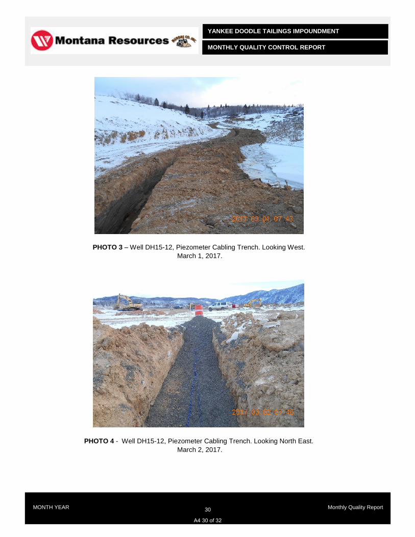
YANKEE DOODLE TAILINGS IMPOUNDMENT
MONTHLY QUALITY CONTROL REPORT
MONTH YEAR 30 Monthly Quality Report
PHOTO 3 – Well DH15-12, Piezometer Cabling Trench. Looking West.
March 1, 2017.
PHOTO 4 - Well DH15-12, Piezometer Cabling Trench. Looking North East.
March 2, 2017.
A4 30 of 32
YANKEE DOODLE TAILINGS IMPOUNDMENT
MONTHLY QUALITY CONTROL REPORT
MONTH YEAR 31 Monthly Quality Report
LABORATORY RESULTS
A4 31 of 32

YANKEE DOODLE TAILINGS IMPOUNDMENT
MONTHLY QUALITY CONTROL REPORT
MONTH YEAR 32 Monthly Quality Report
Insert Split net results, PSD charts, ABA testing etc etc. Organize based on:
- Control – Source Materials Testing
- Control – Stockpile Materials Testing
- Record Materials Testing
A4 32 of 32
MONTANA RESOURCES, LLP
YANKEE DOODLE TAILINGS IMPOUNDMENT
CONSTRUCTION MANAGEMENT PLAN VA101-126/12-5 Rev 3May 1, 2018
APPENDIX A5
REQUEST FOR INFORMATION TEMPLATE
(Page A5-1)

Suite 1400
750 West Pender Street
Vancouver, British Columbia
Canada V6C 2T8
Telephone: 604.685.0543
Facsimile: 604.685.0147
Email: [email protected]
Page 1 of 1
\\KPL\VA-Prj$\1\01\00126\12\A\Report\5 - Construction Management Plan\Rev 2\Appendix A - Reporting Templates\A5_RFI_Template.docx
Knight Piésold
C O N S U L T I N G
Area of work or title of information requested: Details on information requested. Include pictures, drawings, etc as required. Any formal design changes shall be requested using the Design Change Request Template.
Date: YYYY/MM/DD
Project Ref. No:
VA101-00126/15
To: Knight Piésold Ltd.
From: Name, Company
Project: Yankee Doodle Tailings Impoundment
Subject: RFI #00X
REQUEST FOR INFORMATION
A5 1 of 1

MONTANA RESOURCES, LLP
YANKEE DOODLE TAILINGS IMPOUNDMENT
CONSTRUCTION MANAGEMENT PLAN VA101-126/12-5 Rev 3May 1, 2018
APPENDIX A6
DESIGN CHANGE REQUEST TEMPLATE
(Page A6-1)

YANKEE DOODLE TAILINGS IMPOUNDMENT WEST EMBANKMENT
Month, DD, YYYY REQUEST FOR APPROVAL BY DESIGN OFFICE FOR CHANGE/SUBSTITUTION
Knight Piésold C O N S U L T I N G
www.knightpiesold.com
1
CLIENT: MONTANA RESOURCES, LLP PROJECT NO.: VA101-126/15
TO: Ken Brouwer
CC: Steve Czehura (MR), Dan Fontaine (KP)
CHANGE/SUBSTITUTION NO.: Design Change Request #00X PAGES: 1
AREA OF WORK:
Description of Area
GENERAL AREA OF PROPOSED WORK:
Provide the following information (as a minimum) and add additional information as required depending upon
change required:
- Purpose for Change Request
- Review of Change of Design
- Management of Changes
No. of Sheets Attached: Number
Reference Drawings/Clauses:
Originator
Name, Designation, Title
Signature:
FOR DESIGN OFFICE USE
Date Received:
Proposed change substitution (circle one): Not Approved / Approved as Submitted / Approved as Amended:
No. of Sheets Attached: (amendments only)
Engineer Principal
Name: Name:
Title: Title:
Signature: Signature:
Date Returned:
NOTES:
1. Originator to keep a copy of all submissions and attachments.
2. Home office to keep a file copy of completed request form with attachments, marked up as described above.
A6 1 of 1