Embed Size (px)
Citation preview
CSM_H2C_DS_E_2_2
1
Motor Timer
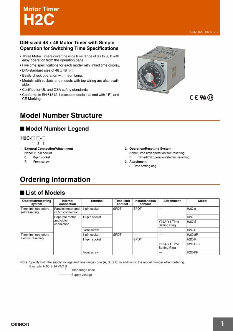
H2CDIN-sized 48 x 48 Motor Timer with Simple Operation for Switching Time Specifications
• Three Motor Timers cover the wide time range of 6 s to 30 h with easy operation from the operation panel.
• Five time specifications for each model with linked time display.
• DIN-standard size of 48 x 48 mm.
• Easily check operation with neon lamp. • Models with sockets and models with top wiring are also avail-
able.
• Certified for UL and CSA safety standards.• Conforms to EN 61812-1 (except models that end with “-F”) and
CE Marking.
Model Number Structure
■ Model Number Legend
1. External Connection/AttachmentNone: 11-pin socket8: 8-pin socketF: Front screw
2. Operation/Resetting SystemNone: Time-limit operation/self-resettingR: Time-limit operation/electric resetting
3. AttachmentS: Time setting ring
Ordering Information
■ List of Models
1 2 3
H2C-@ @-@
Operation/resetting system
Internal connection
Terminal Time-limit contact
Instantaneous contact
Attachment Model
Time-limit operation/ self-resetting
Parallel motor and clutch connection
8-pin socket SPDT SPDT --- H2C-8
Separate motor and clutch connection
11-pin socket H2C
Y92A-Y1 Time Setting Ring
H2C-S
Front screw --- H2C-F
Time-limit operation/ electric resetting
8-pin socket SPDT --- --- H2C-8R
11-pin socket SPDT H2C-R
Y92A-Y1 Time Setting Ring
H2C-R-S
Front screw --- H2C-FR
Note: Specify both the supply voltage and time range code (A, B, or C) in addition to the model number when ordering.Example: H2C-S 24 VAC B
Time range code
Supply voltage
H2C
2
■ Accessories (Order Separately)
Note: 1. Supplied with H2C-S/-R-S models.2. Y92A-48G is a finger safe terminal cover which is attached to the P3G-08 or P3GA-11 Socket.3. Hold-down Clips are sold in sets of two.
Specifications
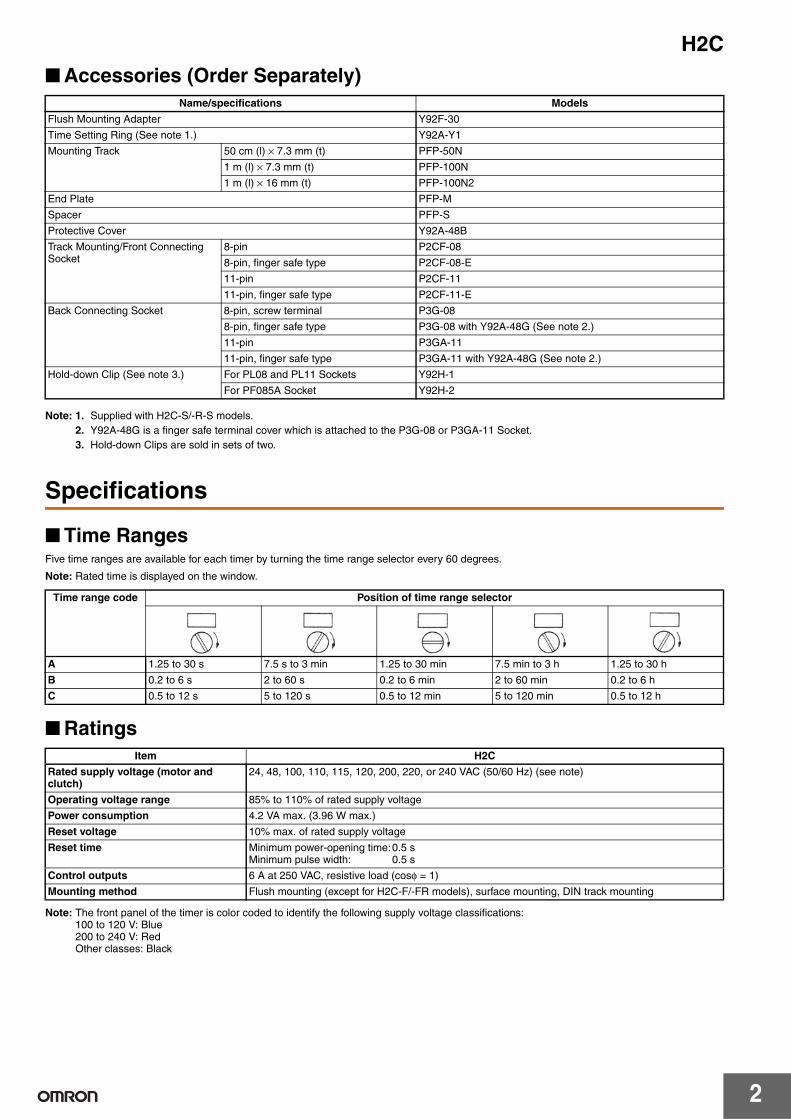
■ Time RangesFive time ranges are available for each timer by turning the time range selector every 60 degrees.
Note: Rated time is displayed on the window.
■ Ratings
Note: The front panel of the timer is color coded to identify the following supply voltage classifications:100 to 120 V: Blue200 to 240 V: RedOther classes: Black
Name/specifications Models
Flush Mounting Adapter Y92F-30
Time Setting Ring (See note 1.) Y92A-Y1
Mounting Track 50 cm (l) × 7.3 mm (t) PFP-50N
1 m (l) × 7.3 mm (t) PFP-100N
1 m (l) × 16 mm (t) PFP-100N2
End Plate PFP-M
Spacer PFP-S
Protective Cover Y92A-48B
Track Mounting/Front Connecting Socket
8-pin P2CF-08
8-pin, finger safe type P2CF-08-E
11-pin P2CF-11
11-pin, finger safe type P2CF-11-E
Back Connecting Socket 8-pin, screw terminal P3G-08
8-pin, finger safe type P3G-08 with Y92A-48G (See note 2.)
11-pin P3GA-11
11-pin, finger safe type P3GA-11 with Y92A-48G (See note 2.)
Hold-down Clip (See note 3.) For PL08 and PL11 Sockets Y92H-1
For PF085A Socket Y92H-2
Time range code Position of time range selector
A 1.25 to 30 s 7.5 s to 3 min 1.25 to 30 min 7.5 min to 3 h 1.25 to 30 h
B 0.2 to 6 s 2 to 60 s 0.2 to 6 min 2 to 60 min 0.2 to 6 h
C 0.5 to 12 s 5 to 120 s 0.5 to 12 min 5 to 120 min 0.5 to 12 h
Item H2C
Rated supply voltage (motor and clutch)
24, 48, 100, 110, 115, 120, 200, 220, or 240 VAC (50/60 Hz) (see note)
Operating voltage range 85% to 110% of rated supply voltage
Power consumption 4.2 VA max. (3.96 W max.)
Reset voltage 10% max. of rated supply voltage
Reset time Minimum power-opening time:0.5 sMinimum pulse width: 0.5 s
Control outputs 6 A at 250 VAC, resistive load (cosφ = 1)
Mounting method Flush mounting (except for H2C-F/-FR models), surface mounting, DIN track mounting
H2C
3
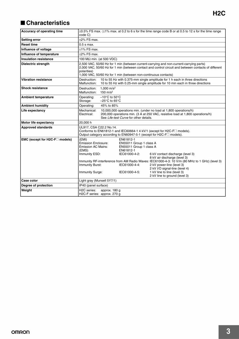
■ CharacteristicsAccuracy of operating time ±0.5% FS max. ⟨±1% max. at 0.2 to 6 s for the time range code B or at 0.5 to 12 s for the time range
code C)
Setting error ±2% FS max.
Reset time 0.5 s max.
Influence of voltage ±1% FS max.
Influence of temperature ±2% FS max.
Insulation resistance 100 MΩ min. (at 500 VDC)
Dielectric strength 2,500 VAC, 50/60 Hz for 1 min (between current-carrying and non-current-carrying parts)2,000 VAC, 50/60 Hz for 1 min (between contact and control circuit and between contacts of different polarities)1,000 VAC, 50/60 Hz for 1 min (between non-continuous contacts)
Vibration resistance Destruction: 10 to 55 Hz with 0.375-mm single amplitude for 1 h each in three directionsMalfunction: 10 to 55 Hz with 0.25-mm single amplitude for 10 min each in three directions
Shock resistance Destruction: 1,000 m/s2
Malfunction: 150 m/s2
Ambient temperature Operating: –10°C to 50°CStorage: –25°C to 65°C
Ambient humidity Operating: 45% to 85%
Life expectancy Mechanical: 10,000,000 operations min. (under no load at 1,800 operations/h)Electrical: 200,000 operations min. (3 A at 250 VAC, resistive load at 1,800 operations/h)
See Life-test Curve for other details.
Motor life expectancy 20,000 h
Approved standards UL917, CSA C22.2 No.14.Conforms to EN61812-1 and IEC60664-1 4 kV/1 (except for H2C-F@ models).Output category according to EN60947-5-1 (except for H2C-F@ models).
EMC (except for H2C-F@ models) (EMI) EN61812-1Emission Enclosure: EN55011 Group 1 class AEmission AC Mains: EN55011 Group 1 class A(EMS) EN61812-1Immunity ESD: IEC61000-4-2: 6 kV contact discharge (level 3)
8 kV air discharge (level 3)Immunity RF-interference from AM Radio Waves: IEC61000-4-3: 10 V/m (80 MHz to 1 GHz) (level 3)Immunity Burst: IEC61000-4-4: 2 kV power-line (level 3)
2 kV I/O signal-line (level 4)Immunity Surge: IEC61000-4-5: 1 kV line to line (level 3)
2 kV line to ground (level 3)
Case color Light gray (Munsell 5Y7/1)
Degree of protection IP40 (panel surface)
Weight H2C series: approx. 180 gH2C-F series: approx. 270 g
H2C
4
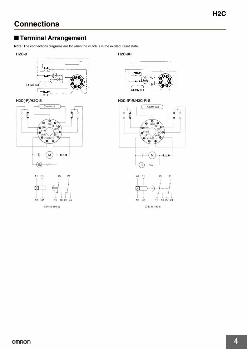
Connections
■ Terminal ArrangementNote: The connections diagrams are for when the clutch is in the excited, reset state.
H2C-8
H2C(-F)/H2C-S H2C-(F)R/H2C-R-S
H2C-8R
(B2) (B1)
(22)
(24)
(A2) (21) (15)
(A1)
(18)
(16) (B2) (B1)
(22)
(24) (A2)
(21) (15) (A1)
(18) (16)
6 7
8
9
10
11 1
2
3
4
5 (B2) (B1)
(22) (24)
(A2) (21) (15)
(A1) (18)
(16)
6 7
8
9
10
11 1
2
3
4
5
Clutch coil
(DIN 46 199-5)
Clutch coil
(DIN 46 199-5)
H2C
5
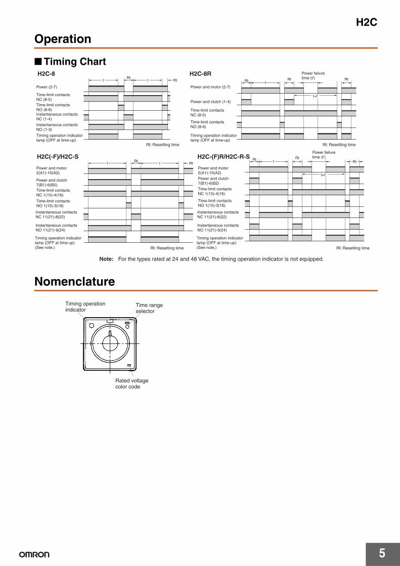
Operation
■ Timing Chart
Nomenclature
t t Rt Rt
t Rt Rt Rt
t+t'
t Rt t Rt t Rt
Rt Rt
t+t'
H2C(-F)/H2C-S H2C-(F)R/H2C-R-S
Rt: Resetting time
Note: For the types rated at 24 and 48 VAC, the timing operation indicator is not equipped.
Rt: Resetting time
H2C-8R H2C-8
Power (2-7)
Instantaneous contacts NC (1-4) Instantaneous contacts NO (1-3)
Timing operation indicator lamp (OFF at time-up)
Power and motor (2-7)
Power and clutch (1-4)
Timing operation indicator lamp (OFF at time-up)
Power failure time (t')
Rt: Resetting time
Instantaneous contacts NC 11(21)-8(22)
Instantaneous contacts NO 11(21)-9(24)
Timing operation indicator lamp (OFF at time-up) (See note.)
Instantaneous contacts NC 11(21)-8(22)
Instantaneous contacts NO 11(21)-9(24)
Timing operation indicator lamp (OFF at time-up) (See note.)
Power failure time (t')
Rt: Resetting time
Time-limit contacts NC (8-5) Time-limit contacts NO (8-6)
Time-limit contacts NC 1(15)-4(16)
Time-limit contacts NO 1(15)-3(18)
Time-limit contacts NC (8-5)
Time-limit contacts NO (8-6)
Time-limit contacts NC 1(15)-4(16)
Time-limit contacts NO 1(15)-3(18)
Power and motor 2(A1)-10(A2)
Power and clutch 7(B1)-6(B2)
Power and motor 2(A1)-10(A2) Power and clutch 7(B1)-6(B2)
Timing operation indicator
Time range selector
Rated voltage color code
H2C
6
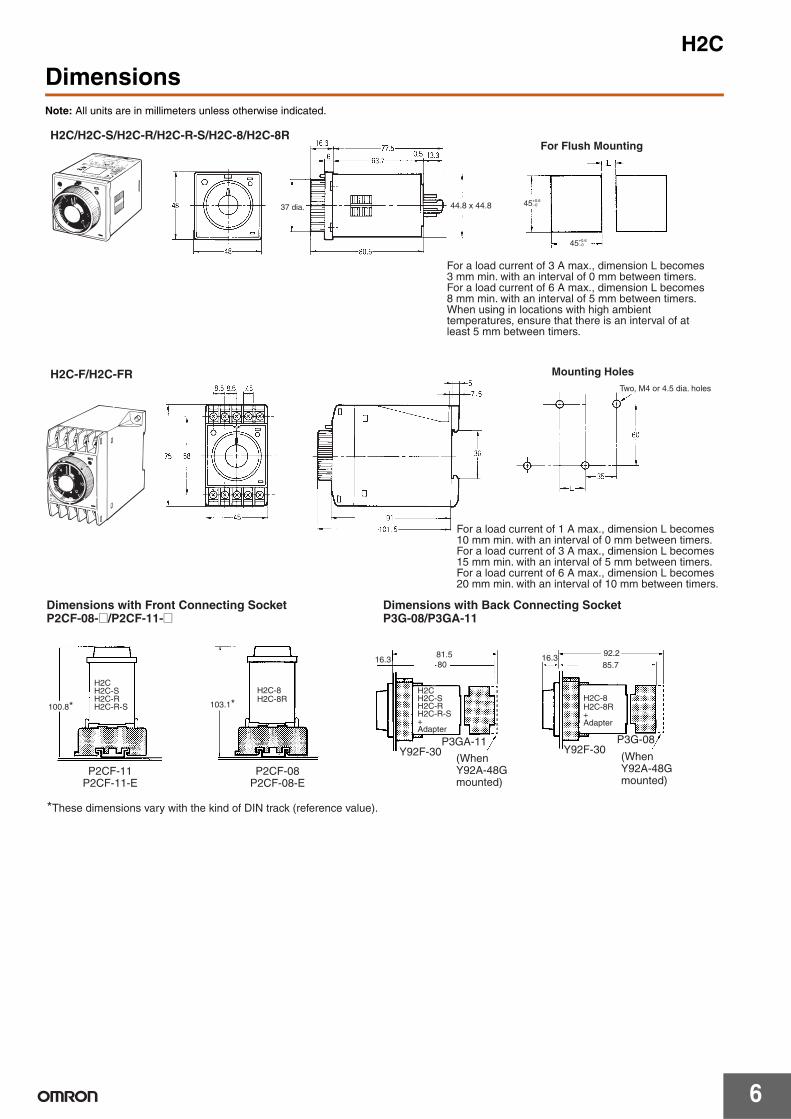
DimensionsNote: All units are in millimeters unless otherwise indicated.
44.8 x 44.8 45+0.6 −0
45+0.6 −0
H2C/H2C-S/H2C-R/H2C-R-S/H2C-8/H2C-8R
H2C-F/H2C-FR
For Flush Mounting
Mounting Holes
For a load current of 3 A max., dimension L becomes 3 mm min. with an interval of 0 mm between timers. For a load current of 6 A max., dimension L becomes 8 mm min. with an interval of 5 mm between timers. When using in locations with high ambient temperatures, ensure that there is an interval of at least 5 mm between timers.
For a load current of 1 A max., dimension L becomes 10 mm min. with an interval of 0 mm between timers. For a load current of 3 A max., dimension L becomes 15 mm min. with an interval of 5 mm between timers. For a load current of 6 A max., dimension L becomes 20 mm min. with an interval of 10 mm between timers.
Two, M4 or 4.5 dia. holes
37 dia.
100.8* 103.1*
80 16.3 16.3
85.7 81.5 92.2
H2C-8 H2C-8R
*These dimensions vary with the kind of DIN track (reference value).
Y92F-30 P3GA-11
Y92F-30 P3G-08
H2C H2C-S H2C-RH2C-R-S
P2CF-11 P2CF-11-E
P2CF-08 P2CF-08-E
H2CH2C-SH2C-RH2C-R-S+Adapter
(When Y92A-48G mounted)
H2C-8 H2C-8R + Adapter
(When Y92A-48G mounted)
Dimensions with Front Connecting Socket P2CF-08-@/P2CF-11-@
Dimensions with Back Connecting Socket P3G-08/P3GA-11
H2C
7
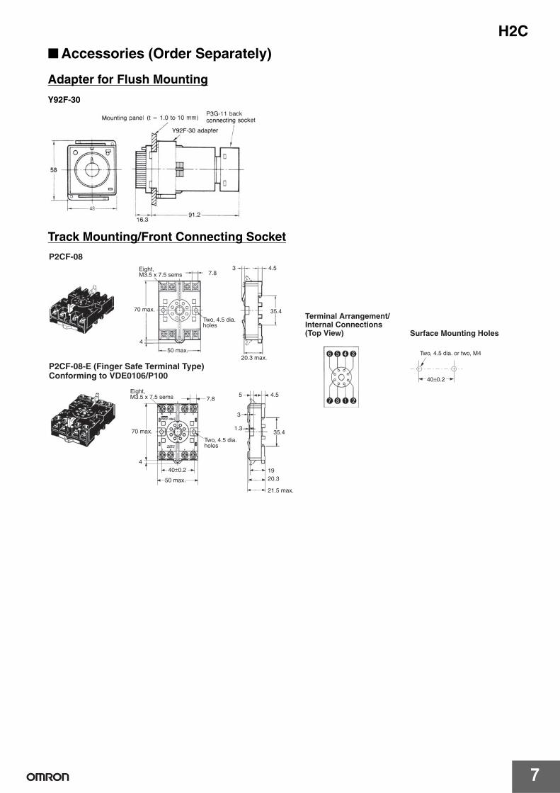
■ Accessories (Order Separately)
Adapter for Flush Mounting
Y92F-30
Track Mounting/Front Connecting Socket
7.83 4.5
35.4
4
40±0.2
40±0.2
7.8
4
35.4
20.319
3
1.3
5 4.5
70 max.
50 max.20.3 max.
P2CF-08-E (Finger Safe Terminal Type)Conforming to VDE0106/P100
Surface Mounting Holes
Two, 4.5 dia. or two, M4
50 max.
70 max.
21.5 max.
P2CF-08Eight, M3.5 x 7.5 sems
Two, 4.5 dia. holes
Terminal Arrangement/Internal Connections (Top View)
Two, 4.5 dia. holes
Eight, M3.5 x 7.5 sems
H2C
8
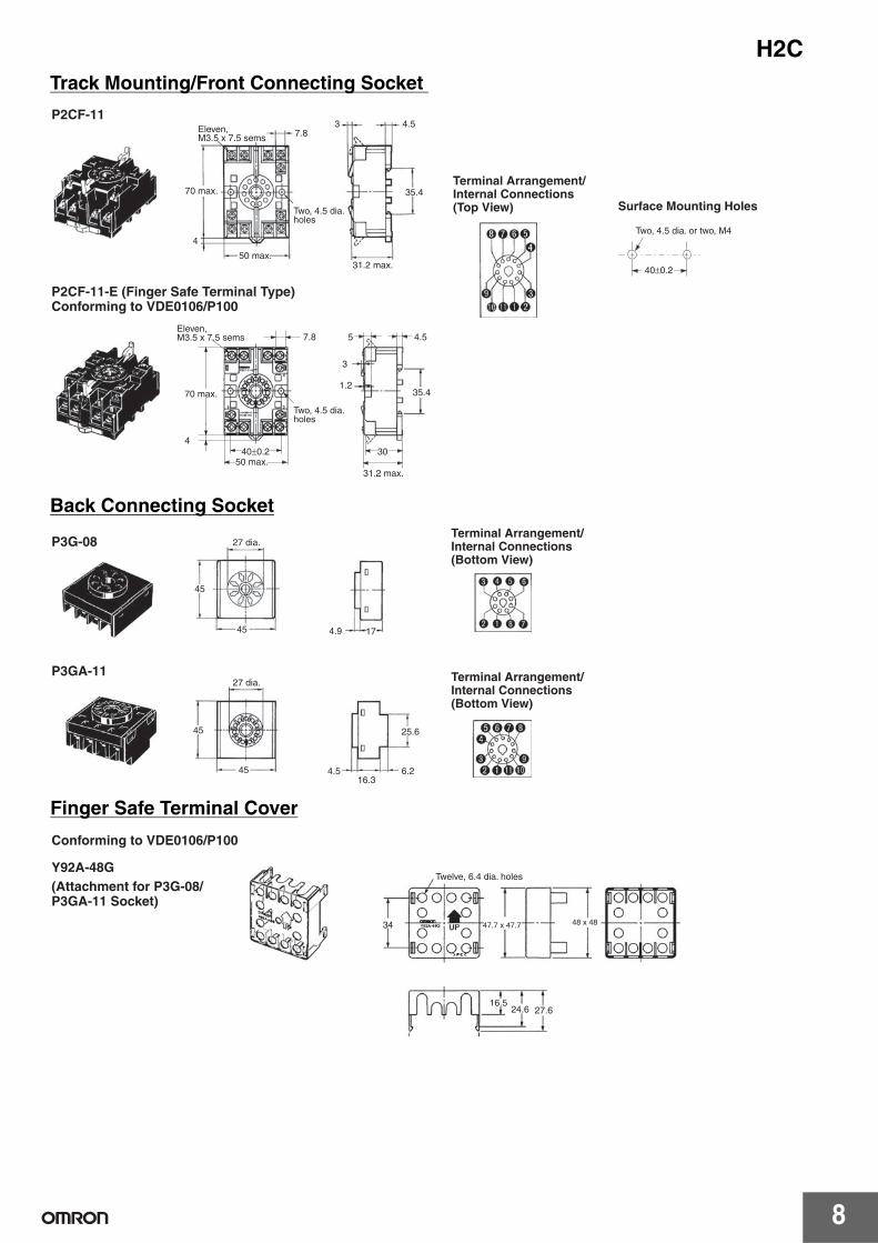
Track Mounting/Front Connecting Socket
Back Connecting Socket
40±0.2
7.83 4.5
35.4
4
7.8
440±0.2
35.4
30
5 4.5
3
1.2
Surface Mounting Holes
Two, 4.5 dia. or two, M4
70 max.
50 max.31.2 max.
P2CF-11-E (Finger Safe Terminal Type)Conforming to VDE0106/P100
70 max.
50 max.31.2 max.
P2CF-11Eleven, M3.5 x 7.5 sems
Terminal Arrangement/Internal Connections (Top View)
Two, 4.5 dia. holes
Two, 4.5 dia. holes
Eleven, M3.5 x 7.5 sems
45
45 4.9 17
45
45
25.6
4.516.3
6.2
34 47.7 x 47.7 48 x 48
16.524.6 27.6
27 dia.
P3GA-1127 dia.
Conforming to VDE0106/P100
Y92A-48GTwelve, 6.4 dia. holes
P3G-08Terminal Arrangement/Internal Connections (Bottom View)
Terminal Arrangement/Internal Connections (Bottom View)
(Attachment for P3G-08/ P3GA-11 Socket)
Finger Safe Terminal Cover
H2C
9
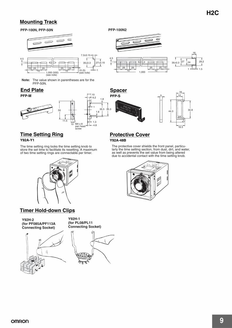
Mounting Track
Timer Hold-down Clips
4.5
15 25 25 25 2510 10
7.3±0.15
35±0.3 27±0.15
1
4.5
15 25 25 25 25 1510 10
35±0.3 27 24
16
29.2
1 1.51,000
PFP-100N2PFP-100N, PFP-50N
1,000 (500) (see note)
Note: The value shown in parentheses are for the PFP-50N.
15 (5) (see note)
50
11.5
106.2
1.8
135.5 35.3
1.8
1.34.8
5
1612
44.3 34.8
16.510 M4 x 8
pan head screw
End PlatePFP-M
SpacerPFP-S
The time setting ring locks the time setting knob to store the set time to facilitate its resetting. A maximum of two time setting rings are connectable per timer.
The protective cover shields the front panel, particu-larly the time setting section, from dust, dirt, and water, as well as prevents the set value from being altered due to accidental contact with the time setting knob.
Time Setting RingY92A-Y1
Protective CoverY92A-48B
Y92H-2(for PF085A/PF113A Connecting Socket)
Y92H-1(for PL08/PL11 Connecting Socket)
H2C
10
Safety PrecautionsRefer to Safety Precautions for All Timers.
!CAUTION
■ Precautions for Safe UseObserve the following items to ensure the safe use of this product.
Environmental Precautions• Store the H2C within the specified ratings. If the H2C has been
stored at temperatures –10°C or lower, let it stand for 3 hours or longer at room temperature before turning ON the power supply.
• Use the H2C within the specified ratings for operating temperature and humidity.
• Do not operate the H2C in locations subject to sudden or extreme changes in temperature, or locations where high humidity may result in condensation.
• Do not use the H2C in locations subject to vibrations or shock. Extended use in such locations may result in damage due to stress.
• Do not use the H2C in locations subject to excessive dust, corrosive gas, or direct sunlight.
• Install the H2C well away from any sources of static electricity, such as pipes transporting molding materials, powders, or liquids.
• The H2C is not waterproof or oil resistant.Do not use it in locations subject to water or oil.
• The life expectancy of internal components may be reduced if the H2C is mounted side-by-side.
• Do not use organic solvents (such as paint thinner or benzine), strong alkaline, or strong acids because they will damage the external finish.
Usage Precautions• Install a switch or circuit breaker that allows the operator to
immediately turn OFF the power, and label it to clearly indicate its function.
• Be sure to wire the terminals correctly.• Do not install input lines in the same duct or conduit as power
supply or other high-voltage lines. Doing so may result in malfunction due to noise. Separate the input lines from high-voltage lines.
• Internal elements may be destroyed if a voltage outside the rated voltage is applied.
• Maintain voltage fluctuations in the power supply within the specified range.
• Use a switch, relay, or other contact so that the rated power supply voltage will be reached within 0.1 s. If the power supply voltage is not reached quickly enough, the H2C may malfunction or outputs may be unstable.
• Leaving the H2C with outputs ON at a high temperature for a long time may hasten the degradation of internal parts (such as electrolytic capacitors). Therefore, use the H2C in combination with relays and avoid leaving the H2C for more than 1 month with an output turned ON.
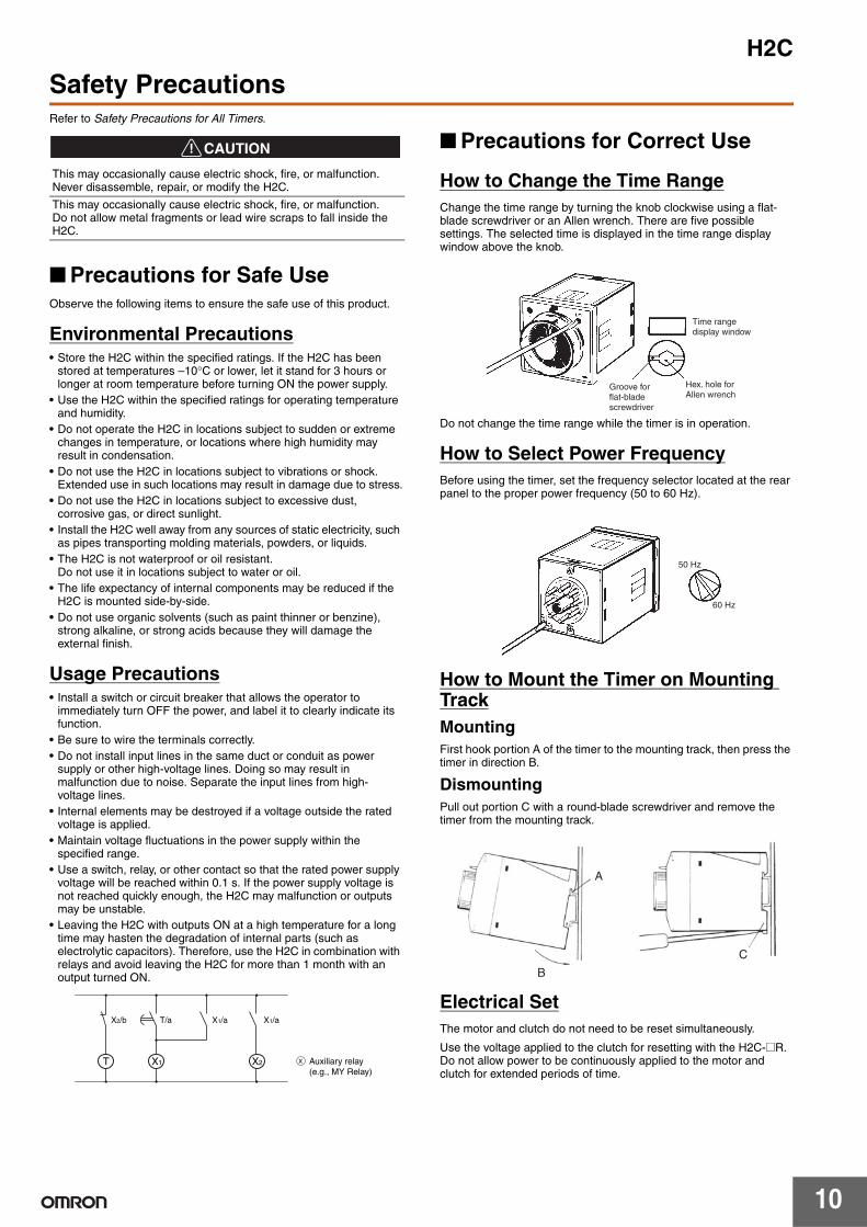
■ Precautions for Correct Use
How to Change the Time RangeChange the time range by turning the knob clockwise using a flat-blade screwdriver or an Allen wrench. There are five possible settings. The selected time is displayed in the time range display window above the knob.
Do not change the time range while the timer is in operation.
How to Select Power FrequencyBefore using the timer, set the frequency selector located at the rear panel to the proper power frequency (50 to 60 Hz).
How to Mount the Timer on Mounting TrackMountingFirst hook portion A of the timer to the mounting track, then press the timer in direction B.
DismountingPull out portion C with a round-blade screwdriver and remove the timer from the mounting track.
Electrical SetThe motor and clutch do not need to be reset simultaneously.
Use the voltage applied to the clutch for resetting with the H2C-@R. Do not allow power to be continuously applied to the motor and clutch for extended periods of time.
This may occasionally cause electric shock, fire, or malfunction.Never disassemble, repair, or modify the H2C.
This may occasionally cause electric shock, fire, or malfunction.Do not allow metal fragments or lead wire scraps to fall inside the H2C.
XX1T X2
X1/aX2/b T/a X1/a
Auxiliary relay (e.g., MY Relay)
Time range display window
Hex. hole for Allen wrench
Groove for flat-blade screwdriver
50 Hz
60 Hz
B
A
C
H2C
11
OthersDo not turn the operation time setting knob beyond the range of the scale. To achieve higher accuracy in setting, measure the operation time while turning the operation time setting knob.
The deviation and setting error for the operation time shows the percent of FS. The absolute value of the deviation and setting error will not change even if the set time is changed. The time specifications should therefore be selected to use the operation time as close to FS as possible.
At high temperatures, the operation voltage will be 90% or less if voltage is applied continuously after timeout. Be sure to keep the voltage within the allowable voltage fluctuation range.
Precautions for EN61812-1The H2C (except for H2C-F@) as a built-in timer conforms to EN61812-1, provided that the following conditions are satisfied.
HandlingBefore dismounting the H2C from the Socket, make sure that no voltage is imposed on any terminal of the H2C.
Applicable Sockets: P2CF-@@, P2CF-@@-E, PF085A, PL@@.
WiringBasic insulation is ensured between the motor circuit, clutch circuit, and control output circuit. (However, the H2C-8 motor circuit and clutch circuit use the same input.) Basic insulation is also ensured between the output circuits of models with instantaneous output.
Basic insulation: Overvoltage category III, pollution degree 1 (See note.)
Operating parts: Reinforced insulation (double insulation)(with a clearance of 5.5 mm and a creepage distance of 5.5 mm at 240 VAC)
Output parts: Basic insulation(with a clearance of 3.0 mm and a creepage distance of 3.0 mm at 240 VAC)
Note: Overvoltage category II, pollution degree 1 if the Timer is mounted to the PL11 Socket.
In the interest of product improvement, specifications are subject to change without notice.
ALL DIMENSIONS SHOWN ARE IN MILLIMETERS.
To convert millimeters into inches, multiply by 0.03937. To convert grams into ounces, multiply by 0.03527.
Read and Understand This Catalog Please read and understand this catalog before purchasing the products. Please consult your OMRON representative if you have any questions or comments.
Warranty and Limitations of Liability WARRANTY OMRON's exclusive warranty is that the products are free from defects in materials and workmanship for a period of one year (or other period if specified) from date of sale by OMRON. OMRON MAKES NO WARRANTY OR REPRESENTATION, EXPRESS OR IMPLIED, REGARDING NON-INFRINGEMENT, MERCHANTABILITY, OR FITNESS FOR PARTICULAR PURPOSE OF THE PRODUCTS. ANY BUYER OR USER ACKNOWLEDGES THAT THE BUYER OR USER ALONE HAS DETERMINED THAT THE PRODUCTS WILL SUITABLY MEET THE REQUIREMENTS OF THEIR INTENDED USE. OMRON DISCLAIMS ALL OTHER WARRANTIES, EXPRESS OR IMPLIED. LIMITATIONS OF LIABILITY OMRON SHALL NOT BE RESPONSIBLE FOR SPECIAL, INDIRECT, OR CONSEQUENTIAL DAMAGES, LOSS OF PROFITS OR COMMERCIAL LOSS IN ANY WAY CONNECTED WITH THE PRODUCTS, WHETHER SUCH CLAIM IS BASED ON CONTRACT, WARRANTY, NEGLIGENCE, OR STRICT LIABILITY. In no event shall the responsibility of OMRON for any act exceed the individual price of the product on which liability is asserted. IN NO EVENT SHALL OMRON BE RESPONSIBLE FOR WARRANTY, REPAIR, OR OTHER CLAIMS REGARDING THE PRODUCTS UNLESS OMRON'S ANALYSIS CONFIRMS THAT THE PRODUCTS WERE PROPERLY HANDLED, STORED, INSTALLED, AND MAINTAINED AND NOT SUBJECT TO CONTAMINATION, ABUSE, MISUSE, OR INAPPROPRIATE MODIFICATION OR REPAIR.
Application Considerations SUITABILITY FOR USE OMRON shall not be responsible for conformity with any standards, codes, or regulations that apply to the combination of products in the customer's application or use of the products. At the customer's request, OMRON will provide applicable third party certification documents identifying ratings and limitations of use that apply to the products. This information by itself is not sufficient for a complete determination of the suitability of the products in combination with the end product, machine, system, or other application or use. The following are some examples of applications for which particular attention must be given. This is not intended to be an exhaustive list of all possible uses of the products, nor is it intended to imply that the uses listed may be suitable for the products:
• Outdoor use, uses involving potential chemical contamination or electrical interference, or conditions or uses not described in this catalog. • Nuclear energy control systems, combustion systems, railroad systems, aviation systems, medical equipment, amusement machines, vehicles,
safety equipment, and installations subject to separate industry or government regulations. • Systems, machines, and equipment that could present a risk to life or property.
Please know and observe all prohibitions of use applicable to the products. NEVER USE THE PRODUCTS FOR AN APPLICATION INVOLVING SERIOUS RISK TO LIFE OR PROPERTY WITHOUT ENSURING THAT THE SYSTEM AS A WHOLE HAS BEEN DESIGNED TO ADDRESS THE RISKS, AND THAT THE OMRON PRODUCTS ARE PROPERLY RATED AND INSTALLED FOR THE INTENDED USE WITHIN THE OVERALL EQUIPMENT OR SYSTEM. PROGRAMMABLE PRODUCTS OMRON shall not be responsible for the user's programming of a programmable product, or any consequence thereof.
Disclaimers CHANGE IN SPECIFICATIONS Product specifications and accessories may be changed at any time based on improvements and other reasons. It is our practice to change model numbers when published ratings or features are changed, or when significant construction changes are made. However, some specifications of the products may be changed without any notice. When in doubt, special model numbers may be assigned to fix or establish key specifications for your application on your request. Please consult with your OMRON representative at any time to confirm actual specifications of purchased products. DIMENSIONS AND WEIGHTS Dimensions and weights are nominal and are not to be used for manufacturing purposes, even when tolerances are shown. PERFORMANCE DATA Performance data given in this catalog is provided as a guide for the user in determining suitability and does not constitute a warranty. It may represent the result of OMRON’s test conditions, and the users must correlate it to actual application requirements. Actual performance is subject to the OMRON Warranty and Limitations of Liability. ERRORS AND OMISSIONS The information in this document has been carefully checked and is believed to be accurate; however, no responsibility is assumed for clerical, typographical, or proofreading errors, or omissions.
2009.9
In the interest of product improvement, specifications are subject to change without notice.
OMRON Corporation Industrial Automation Company http://www.ia.omron.com/
(c)Copyright OMRON Corporation 2009 All Right Reserved.