Embed Size (px)
Citation preview

Motorrahmen
Lattoflex 282/382/9822-Motorer
Lattoflex 283/383/9833-Motorer
Lattoflex 284/384/9844-Motorer
Motor frames / Sommier motorisé
Montage- & Bedienungsanleitung deutsch Wichtiges Dokument. Bitte sorgfältig aufbewahren!
Installation and operating instructions english Important document. Please keep in a safe place.
Instructions de montage et d’utilisation français Document important. A conserver avec soin.

2
InhaltsverzeichnisAbbildungen ....................................................................................................3Montage, Anschluss und Bedienung .............................................................4 - 7Sicherheitshinweise ..........................................................................................7Reinigung und Pflege ........................................................................................7 Technische Daten ...........................................................................................19
Contents Illustrations ......................................................................................................3Installation, connection and operation .........................................................8 - 11Safety instructions .........................................................................................11Care instructions ...........................................................................................11Technical data ...............................................................................................19
SommaireIllustration ........................................................................................................3Montage, raccordement et utilisation ........................................................12 - 15Consignes de sécurité ....................................................................................16Conseils d’entretien ........................................................................................16Caractéristiques techniques ...........................................................................19

3
1
2
3
max. 8 cm
max. 4 cm
ca. 70 cm
ca. 14 cmca. 5 cm

4
1
2
3
2-Motorer (x82)mit Kabelhandschalter
Bitte gehen Sie zur Inbetriebnahme Ihres Motorrahmens wie folgt vor:
1 Transportschutz: Klettbänder ent fernen. Pappdeckel unter dem Rahmen entfernen.
2 Fußteil des Rahmens hochklappen, Zugriff auf die schwarze Stoff tasche (Anschlusszubehör).
3 Steuerungsbox und Netzgerät aus packen.
4 Motorrahmen ans Stromnetz anschließen.
5 Steuerungsbox kann seitlich am Ober-schenkelmotor aufgeschoben werden.
Motorrahmen per Kabelhandschalter verstellen.
Montagehinweise
Anschluss und Inbetriebnahme
Rahmentyp und SeriennummerDas Typenschild finden Sie am Kopfende auf dem linken Längsholm unter der Kopfhoch lagerung.
Mitgeliefertes ZubehörMontagezubehör: Matratzenhalter (Fußende), 4 AntirutschfolienAnschlusszubehör: Netzgerät, Zuleitungskabel, Steuerungsbox, Kabel-Handschalter (x82), Funk-Fernbedienung (x83 und x84)
Einlegen in ein Bett/Bodenfreiheit:Bitte berücksichtigen Sie den notwen-digen Platzbedarf für die verstellbaren Rahmenteile z.B. bei Dachschrägen, Bettüberbauten oder gepolsterten Kopfteilen. Für die Verstell mechanik und Antriebstechnik im Unterbau wird eine Einbautiefe (Bodenfreiheit) von ca. 14 cm benötigt.
Bitte beachten Sie immer den Abstand des motorisch verstellbaren Rückenteils zum Kopf teil des Bettes. In Flachlage sollte hier ein Ab stand von mindestens 1,5 cm bestehen. Um ein unbeabsich-tigtes Verrutschen auszuschließen, den Rahmen bitte an vorgebohrten Punkten im Metallunterbau mit dem Bett ver-schrauben.
Seitliche Auflageleisten dürfen maximal 4 cm breit sein (Mittelzarge 8 cm). Der Motorrahmen muss immer spannungsfrei ins Bett passen.
Bei Betten mit Dreiecksauflagen (Schen-kellänge max. 15 cm) bitte den Einbau-satz „Verlängerungselemente“ verwen-den (als Zubehör erhältlich).
Wir empfehlen für eine stabile Bettkon-struktion bei Dreiecksauflagen immer einen Auflagepunkt in der Bettseiten-mitte.
AntirutschfolieAn den Auflagepunkten des Rahmens im Bettgestell anbringen. Die Folien verhin-dern Geräusche, die durch Verrutschen der Rahmen im Bettgestell entstehen können.
MatratzenhalterDen mitgelieferten Halter am Fußende anbringen. Die Kunststoffschellen sind vormontiert.

5
3-Motorer (x83) mit Funk-Fernbedienung 4-Motorer (x84) mit Funk-Fernbedienung
Bitte gehen Sie zur Inbetriebnahme Ihres Motorrahmens wie folgt vor:
1 Transportschutz: Klettbändern ent fernen. Pappdeckel unter dem Rahmen entfernen.
2 Fußteil des Rahmens hochklappen, Zugriff auf die schwarze Stoff tasche (Anschlusszubehör).
3 Fernbedienung auspacken und Batterien einlegen.
4 Steuerungsbox und Netzgerät aus packen.
5 Steuerungsbox kann seitlich am Unter schenkelmotor aufgeschoben werden.
6 Fernbedienung bereithalten! Netzgerät an die Steuerungsbox und ans Stromnetz anschließen.
7 Nachdem die Steuerung Strom be-kommen hat, innerhalb von 30 Sekunden eine beliebige Taste der Fernbedienung drücken (Plug & Connect Funktion).
Die Fernbedienung ist nun an diesem Motorrahmen angelernt.Wenn der Anlernvorgang nicht erfolg-reich war, dann blinkt die Tastatur-beleuchtung im Wechsel mit der Status LED. In diesem Fall bitte den Anlern-taster an der Steuerungsbox drücken.
Anschluss und Inbetriebnahme
Einstellungen vornehmen
a Alle Antriebe gleichzeitig aufwärtsb alle Antriebe gleichzeitig abwärtsc Rückenverstellung aufwärtsd Rückenverstellung abwärtse Beinverstellung aufwärtsf Beinverstellung abwärts
Verwenden Sie die Tasten a bis f. Solange Sie eine Taste drücken wird der entsprechende Antrieb verfahren.
a
fe
dc
b2-Motorer (x82)mit Kabelhandschalter

6
Einstellungen vornehmen
Verwenden sie die verschiedenen „Auf“- und „Ab“-Tasten zum Verstellen Ihres Rahmens. Solange Sie eine Taste drücken, wird der entsprechende Antrieb verfahren.Beim 3-Motorer sind die oberen 2 Tasten (Kopfverstellung) nicht belegt.
Mit schalten Sie die integrierte Taschenlampe an.
Mit schalten Sie die Unterbettbeleuchtung an und wieder aus (optionales Zubehör).
Mit den Tasten rufen Sie ihre Lieblingseinstellungen ab.
Zum Nullstellen aller Antriebe halten Sie bitte die Taste gedrückt.
3-Motorer (x83) mit Funk-Fernbedienung 4-Motorer (x84) mit Funk-Fernbedienung
1 Verstellen Sie den Rahmen in die gewünschte Position.
2 Die Taste 3x kurz drücken.3 Sofort danach eine der Tasten M1 –
M3 drücken.
Die aktuelle Position ist auf der ent- s prechenden M-Taste zugewiesen und nun abrufbar.
Abspeichern der Lieblings positionen Manuelles Anlernen nach der ersten Inbetriebnahme:
1 Anlernknopf an der Steue-rungsbox drücken, weiße LED leuchtet.
2 Die Tasten „Kopf hoch“ und „Kopf runter“ gleichzeitig drücken. Die weiße LED erlischt.
Die Fernbedienung ist nun an diesem Motorrahmen angelernt.
Sonderfunktion Parallel-Lauf:
Bei Bedarf können mit einer Fernbedie-nung zwei Motorrahmen gleichzeitig angesteuert werden. Dazu im Doppelbett eine bereits angelernte Fernbedienung zusätzlich am zweiten Motorrahmen manuell anlernen. Hierbei handelt es sich aber nur um ein gleichzeitiges Ansteuern.
Durch unterschiedliche Belastungen können unterschiedliche Einstellungen entstehen.
Die vor der Parallelschaltung unter M1, M2 und M3 gespeicherten Positionen bleiben je Rahmen individuell erhalten.

7
Sicherheitshinweise
Beim Betätigen und im hochgestellten Zustand nicht auf den Rahmen steigen. Der Rahmen ist so konstruiert, dass bei Betätigung normalerweise keine Einklemm- oder Quetschgefahr besteht. Achten Sie trotzdem darauf, dass sich bei Betätigung des Rahmens keine Per-sonen, insbesondere keine Kinder unter dem Rahmen befinden oder in den Mechanismus hineingreifen. Lattoflex 282 bis 984 sind Einlegerahmen für Bettgestelle. Die Nutzung ist nur nach den Maßgaben dieser Anleitung und nur für den Hausgebrauch vorgesehen. Niemals die Kabel einklemmen, scharf-kantig verlegen oder durch bewegliche Rahmenteile quetschen. Beschädigte An-schlussleitungen nur gegen Originalteile ersetzen. Beschädigungsgefahr durch Kürzen der Tragholme oder durch Demontage von Beschlagteilen.
Verstauen Sie keine Gegenstände unter dem Rahmen. Besonders Bettwäsche kann durch die Motoren Schaden nehmen.
Reinigung und Pflege
Ihre Lattoflex Unterfederung braucht keine besondere Pflege. Es genügt, wenn Sie sie einfach ab und zu mit einem feuchten Tuch abwischen. Bitte ver-wenden Sie weder Lösungsmittel oder Benzin, noch ätzende oder scheuernde Mittel. Immer den Netzstecker während der Reinigung aus der Steckdose ziehen.
Gelegentlich auftretende Geräusche an Kunststofflagern können mit Silikon oder besser mit Flonium behandelt werden. Benutzen Sie in keinem Fall handels-übliche Öle oder Fette.
Sonderfunktion Werkeinstellung:
Fernbedienung:
Diese 3 Tasten (Kopf, Rücken Unter-schenkel runter) so lange drücken, bis die Status-LED dauerhaft leuchtet.
Steuerungsbox:
Den Taster ca. 10 Sekunden lang gedrückt halten, bis die weiße LED einmal aufleuch-tet. Es sind nun keine Fernbedienungen mehr mit dem Rahmen verbunden.

8
1
2
3
Installation instructionsFrame type and serial numberThe name plate is located at the head end on the left longitudinal beam below the raised head.
Supplied accessoriesInstallation accessories: mattress holder (foot end), 4 non-slip foilsConnection accessories: mains adapter, lead cable, control box, cable hand switch (x82), radio remote control (x83 und x84)
Placing in a bedPlease heed the necessary space for the adjustable frame parts, e.g. in rooms with inclined roofs, superstructures over the bed or padded head sections. An installation depth of approx. 14 cm (floor clearance) is needed in the substructure for the adjustment mechanism and drive system. Please always heed the spacing of the back part with its motorised adjustment, to the head part of the bed. There should be spacing of at least 1.5 cm here when the bed is laid flat. To rule out any unintentional slipping, please screw the frame to the bed at the pre-drilled points in the metal substructure.
Side support sections must not exceed 4 cm in width (middle frame 8 cm). The motor frame must always fit in the bed without any tension. For beds with trian-gular supports (leg length max. 15 cm), please use the „Extension elements“ in-stallation kit (available as accessory). For a stable bed structure, we always recom-mend a supporting point in the middle of the bed for triangular supports.
Non-slip foilAffix in the bed structure to the supporting point of the frame. The foils prevent any noi-se that could be caused by the frame slipping in the bed structure.
Mattress holderAttach the supplied holder at the foot end. The plastic clamps are premounted.
2-Motorer (x82)mit Kabelhandschalter
Please proceed as follows to commission your motor frame:
1 Transport protection: Remove the Velcro® fastenings and the card-boards under the frame.
2 Hinge up the foot part of the frame, access to the black fabric pocket
3 Unpack control box and power adapter.
4 Connect motor frame to mains.5 Control box can be pushed onto the
thigh motor at the side.Adjust motor frame with cable hand switch.
Connection and commissioning

9
3-motor version (x83) with radio remote control4-motor version (x84) with radio remote control
Please proceed as follows to commission your motor frame:
1 Transport protection: Remove the Velcro® fastenings and the card-boards under the frame.
2 Hinge up the foot part of the frame, access to the black fabric pocket (connection accessories).
3 Unpack remote control and insert batteries.
4 Unpack control box and power adapter.
5 Control box can be pushed onto the calf motor at the side.
6 Keep remote control at the ready! Connect power adapter to the control box and to the mains
7 As soon as the control has power, press any button on the remote con-trol within 30 seconds (Plug & Connect function).
The remote control has now been confi-gured to this motor frame.If the configuration (“teaching”) was not successful, the light in the button flashes alternately with the status LED. In this case, please press the teach button on the control box.
Connection and commissioning
Adjust the settings
a All drives up at the same timeb All drives down at the same timec Back adjustment upd Back adjustment downe Leg adjustment upf Leg adjustment down
Use the buttons a to f. The correspon-ding drive moves as long as you press and hold a button.
a
fe
dc
b2-motor version (x82) with cable hand switch

10
Adjust the settings
Use the various “up” and “down” buttons to adjust your frame. The corresponding drive moves as long as you press and hold a button. In the 3-motor version, the two top buttons (head adjustment) do not have a function.
Press to turn the integrated torch on.
Press to turn the underbed lighting on and off again (optional accessory).
Press the buttons to activate your favourite settings.
Please press and hold the button to reset all drives to zero.
3-motor version (x83) with radio remote control4-motor version (x84) with radio remote control
1 Adjust the frame to the required position
2 Press the button briefly 3 times.3 Then press one of the buttons
M1 - M3 immediately.
The current position is now allocated to the corresponding M-button and can be activated accordingly
Save your favourite positions Manual teaching after initial commissioning:
1 Press teach button on the control box; white LED lights up.
2 Press the buttons “Head up” and “Head down” at the same time. The white LED goes off again.
The remote control has now been configured to this motor frame.
Special parallel function:
If necessary, two motor frames can be controlled at the same time with one remote control. To use this function for a double bed, take the remote control that has already been configured and proceed with manual configuration („teaching”) at the second motor frame. This only refers to simultaneous control.
Different loads can result in different settings.
The positions saved for M1, M2 and M3 before changing over to the parallel function remain saved individually for each frame.

11
Safety instructions
Do not climb on the frame when it is be-ing adjusted and when it is raised. The frame is designed so that it normally poses no risk of getting clamped or crushed during operation. Even so, please make sure that there is nobody, in particular no child, under the frame or in a position to reach into the mecha-nism when raising or lowering the frame. Lattoflex 282 to 984 are inlay frames for bed structures. They are only intend-ed for use according to the conditions stated in these instructions and only for domestic use.
Make sure that the cables are never clamped, placed over sharp edges or crushed between moving parts of the frame. Only use original parts to replace damaged connection leads. Shortening the support beams or dismantling attach-ment parts poses a risk of damage.
Do not store any items under the frame. Bedding in particular can be damaged by the motors.
Cleaning and careYour Lattoflex spring base does not need any special care. Simply wipe it down from time to time with a damp cloth. Please do not use any solvents or benzene, or any caustic or scouring cleaning agents! Always take the mains plug out of the socket before cleaning.
Use silicone or preferably Flonium to treat any noises coming from the running surfaces of the sliding function or plastic bearings. Never use commercially available oil or grease.
Special function default setting:
Radio remote control:
Hold and press these 3 buttons (head/ back/calf down) until the status LED lights up and stays on.
Control box:
Press and hold the button for approx. 10 seconds until the white LED lights up once. There are now no longer any remote controls connected to the frame.

12
1
2
3
Instructions de montageType de sommier et numéro de sérieLa plaque signalétique se situe côté tête sur le longeron gauche sous le relèvement de la tête.
Accessoires fournisAccessoires de montage : cales pour matelas (côté pieds), 4 bandes antidérapantesAccessoires de raccordement : bloc-system, cordon d’alimentation,boîtier de commande, télécommande filaire (x82), télécommande sans fil (x83 et x84)
Pose dans un lit :Tenez impérativement compte de l‘espace nécessaire au déplacement des pièces ré-glables du sommier, p. ex. en sous-pente, lors d‘une tête de lit surélevée ou d‘un dosseret matelassé. La mécanique de déplacement et la tech-nique d‘entraînement intégrées au châssis exigent une profondeur d‘implantation (garde au sol) d‘env. 14 cm.
Respectez toujours la distance de la partie dorsale à réglage motorisé par rapport à la tête de lit. La distance devrait comporter au moins 1,5 cm en position horizontale. Il est recommandé, en vue d‘exclure un glissement inopiné, de fixer le sommier avec des vis au cadre de lit en se servant des taraudages respectifs prévus sur le châssis métallique.
La largeur des barres d‘appui latérales ne doit pas dépasser 4 cm (8 cm au milieu du châssis).
Veillez à ce que le sommier motorisé soit toujours adapté au lit sans la moindre contrainte.Veuillez utiliser le jeu de pièces des « éléments de rallonge » (disponible comme accessoire) pour les lits équi-pés d‘appuis triangulaires (longueur des branches de 15 cm maximum). Nous re-commandons toujours de prévoir un point d‘appui au milieu du lit afin de garantir une construction solide des lits à appuis triangulaires.
Bande antidérapanteAppliquez-les sur les points d’appui du sommier dans le cadre de lit. Les bandes préviennent les nuisances sonores sus-ceptibles de provenir du glissement du sommier installé dans le cadre de lit.
Cale pour matelasInstallez la cale fournie côté pieds. Les brides de fixation en plastique sont pré-montées.

13
Raccordement et mise en serviceCommande de 2 moteurs par télécommande filaire (x82)
Procédez comme suit pour mettre votre sommier motorisé en service :
1 Protection de transport: Supprimez les grâce à des bandes et le carton au-dessous du cardre.
2 Relevez le côté pieds du cadre pour accéder au sachet en tissu noir (ac-cessoires de raccordement).
3 Déballez le boîtier de commande et le bloc-secteur.
4 Raccordez le sommier motorisé au secteur.
5 L’ouverture du boîtier de commande est possible sur le côté au niveau du moteur de déplacement des cuisses.
Réglez le sommier motorisé avec la télé-commande filaire.
Paramétrages individuels
a Relèvement simultané de tous les moteurs
b Abaissement simultané de tous les moteurs
c Relèvement du dossierd Abaissement du dossiere Relèvement des jambesf Abaissement des jambes
Servez-vous des touches de a à f. Le moteur se déplace tant que vous appuyez sur la touche s’y rapportant.
a
fe
dc
b
Commande de 2 moteurs par télécommande filaire (x82)

14
Commande de 3 moteurs par télécommande sans fil (x83)Commande de 4 moteurs par télécommande sans fil (x84)
Procédez comme suit pour mettre votre sommier motorisé en service :
1 Protection de transport: Supprimez les grâce à des bandes et le carton au-dessous du cardre.
2 Relevez le côté pieds du cadre pour accéder au sachet en tissu noir (accessoires de raccordement).
3 Déballez la télécommande et insérez les piles.
4 Déballez le boîtier de commande et le bloc-secteur
5 L’ouverture du boîtier de commande est possible sur le côté au niveau du moteur de déplacement des mollets.
6 Placez la télécommande à portée de main. Raccordez le bloc-secteur au boîtier de commande et au secteur.
7 Dès que la commande est alimentée en tension, appuyez sur une touche quelconque de la télécommande en l’espace de 30 secondes (fonction branché & connecté).
La télécommande est dorénavant configurée pour ce sommier motorisé.
Si la configuration a échoué, les touches de la commande clignotent par alternance avec la diode d’état. Veuillez appuyer sur la touche de configuration du boîtier de commande dans un tel cas.
Raccordement et mise en service
Paramétrages individuels
Servez-vous des différentes touches pour le déplacement « vers le haut » et « vers le bas » de votre sommier. Le moteur se déplace tant que vous appuyez sur la touche s’y rapportant.Les 2 touches du haut (de la têtière réglable) ne sont pas affectées pour les sommiers à 3 moteurs.
Appuyez sur la touche pour allumer la lampe de poche intégrée
Servez-vous de la touche pour allumer et éteindre l’éclairage sous de lit (accessoire en option).
Appuyez sur les touches pour accéder à vos réglages préférés.
Appuyez sans relâcher sur la touche pour remettre tous les moteurs à zéro.
Commande de 3 moteurs par télécommande sans fil (x83)Commande de 4 moteurs par télécommande sans fil (x84)
15
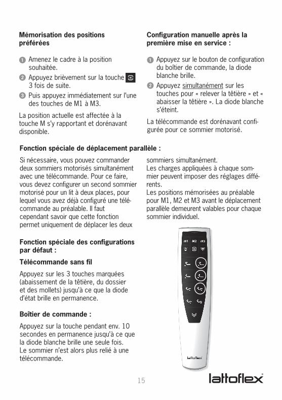
1 Amenez le cadre à la position souhaitée.
2 Appuyez brièvement sur la touche 3 fois de suite.
3 Puis appuyez immédiatement sur l’une des touches de M1 à M3.
La position actuelle est affectée à la touche M s’y rapportant et dorénavant disponible.
Mémorisation des positions préférées
Configuration manuelle après la première mise en service :
1 Appuyez sur le bouton de configuration du boîtier de commande, la diode blanche brille.
2 Appuyez simultanément sur les touches pour « relever la têtière » et « abaisser la têtière ». La diode blanche s’éteint.
La télécommande est dorénavant confi-gurée pour ce sommier motorisé.
Fonction spéciale de déplacement parallèle :
Si nécessaire, vous pouvez commander deux sommiers motorisés simultanément avec une télécommande. Pour ce faire, vous devez configurer un second sommier motorisé pour un lit à deux places, pour lequel vous avez déjà configuré une télé-commande au préalable. Il faut cependant savoir que cette fonction permet uniquement de déplacer les deux
sommiers simultanément.Les charges appliquées à chaque som-mier peuvent imposer des réglages diffé-rents.Les positions mémorisées au préalable pour M1, M2 et M3 avant le déplacement parallèle demeurent valables pour chaque sommier individuel.
Fonction spéciale des configurations par défaut :
Télécommande sans fil
Appuyez sur les 3 touches marquées (abaissement de la têtière, du dossier et des mollets) jusqu’à ce que la diode d’état brille en permanence.
Boîtier de commande :
Appuyez sur la touche pendant env. 10 secondes en permanence jusqu’à ce que la diode blanche brille une seule fois. Le sommier n’est alors plus relié à une télécommande.

16
Consignes de sécuritéNe montez pas sur le sommier en cours d’actionnement et en l’état relevé. Le sommier est conçu de sorte à exclure les risques de coincement ou d’écrasement en actionnement normal. Nous vous recommandons toutefois de vérifier que personne, et notamment aucun enfant, ne se trouve sous le sommier lors de son ac-tionnement, ou puisse introduire quoi que ce soit dans le mécanisme. Les produits Lattoflex de 282 à 984 sont des sommiers à intégrer dans des cadres de lit. L’utilisation est uniquement autori-sée dans le respect de ces instructions et pour un usage personnel.Ne coincez jamais les câbles, veillez à ne pas les faire passer sur des arêtes vives en les posant et à éviter leur écrasement par les éléments en mouvement du som-mier. Ne remplacez les câbles de raccor-dement endommagés que par des pièces d’origine. Vous risquez de dégrader les longerons en les raccourcissant ou les
armatures en les démontant. Ne rangez rien sous le sommier. Les moteurs risquent toujours d’endommager les parures de lit.
Nettoyage et entretienVotre sommier Lattoflex ne nécessite pas d’entretien particulier. Il suffit de l’es-suyer de temps en temps avec un chiffon humide. N’utilisez ni solvant ou essence et renoncez aux produits caustiques ou abrasifs. Retirez toujours la fiche de la prise au secteur pendant le nettoyage.Traitez les nuisances sonores se présen-tant parfois au niveau des surfaces de déplacement de la fonction coulissante ou des paliers en plastique avec de la sili-cone ou, de préférence, avec du Flonium. Ne vous servez en aucun cas d’huiles ou de graisses disponibles dans le com-merce.

17

18

19
Technische DatenDie Motoren arbeiten mit einer Sicherheits-Kleinspannung von max. 29 V DC.Netzanschluss 100 V – 230 V, 50 Hz bis 60 Hz (Einphasen-Wechselstrom), max. 2,0 AEinschaltdauer bei maximaler Dauerlast 2min „ON“ – 18min „OFF“Schutzklasse IP20Standby ca. 0,8 WattKabel-Handschalter 24 V GleichstromFunk-FernbedienungStromversorgung 3 Batterien 1,5 V AAA, alternativ sind Akkus 1,2V einsetzbarFunk-Frequenz 2,4 Ghz, Sendeleistung <1mWLED-Taschenlampe 0,1 Watt
Technical DataThe motors work with safe low voltage of max. 29V DC.Mains connection 100 V – 230 V, 50 Hz to 60 Hz (single phase alternating current), max. 2.0 ASwitch-on period 2 min ON at maximum continuous load, 18 min OFFProtection class IP20Standby approx. 0.8 WCable hand witch 24 V direct currentRadio remote controlPower supply 3 x 1.5 V AAA batteries or 1.2V rechargeable batteriesRadio frequency 2.4 GHz, transmitting power <1mWLED torch 0.1 W
Caractéristiques techniquesLes moteurs fonctionnent avec un courant de sécurité à faible tension de 29 Volts C.C. maximumRaccord au réseau 100 V – 230 V, 50 Hz à 60Hz (courant alternatif monophasé), 2,0 A maximumDurée de branchement 2 minutes « ON » – 18 minutes « OFF » en charge permanente maximaleCatégorie de protection IP20Mode de veille env. 0,8 WattTélécommande filaire 24 V courant continuTélécommande radioAlimentation en courant 3 piles de 1,5 Volts AAA, l'utilisation d'accumulateurs de 1,2 Volts est possible en
alternativeFréquence radio 2,4 Ghz, puissance d'émission < à 1 mWDEL d'éclairage 0,1 Watt

9600
4735
2000
0 Ve
rsio
n 1/
18 –
Sta
nd N
ovem
ber
2018
· te
chni
sche
Änd
erun
gen
vorb
ehal
ten
www.lattoflex.com
Lattoflex · Walkmühlenstraße 93 · 27432 Bremervörde Tel. +49 4761 979 0 · Fax +49 4761 979 161 · [email protected]