Embed Size (px)
Citation preview

Motor switches Dimensions
Motorschalter Maßzeichnungen
108117
Gekapselte MotorschalterMotor switches in enclosure
Gekapselte Motorschalter
MotorschalterMotor switches
107
108
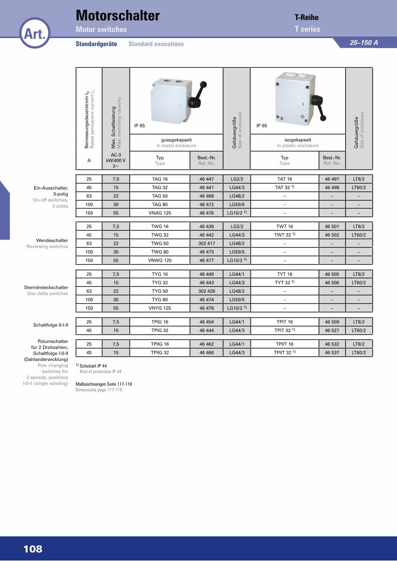
25–150 A
Bem
essu
ngsd
auer
stro
m I u
Rat
ed p
erm
anen
t cur
rent
I u
Max
. Sch
altle
istu
ngM
ax. s
witc
hing
cap
acity
Geh
äuse
grö
ße
Siz
e o
f enc
losu
re
Geh
äuse
grö
ße
Siz
e o
f enc
losu
re
gussgekapselt in metal enclosure
isogekapseltin plastic enclosure
AAC-3
kW/400 V 3~
Typ Type
Best.-Nr. Ref. No.
TypType
Best.-Nr.Ref. No.
25 7,5 TAG 16 46 447 LG2/2 TAT 16 46 497 LT8/2
45 15 TAG 32 46 441 LG44/3 TAT 32 1) 46 498 LT60/2
63 22 TAG 50 46 468 LG48/2 – – –
100 30 TAG 80 46 472 LG59/6 – – –
150 55 VNAG 125 46 476 LG10/2 1) – – –
25 7,5 TWG 16 46 439 LG2/2 TWT 16 46 501 LT8/2
45 15 TWG 32 46 442 LG44/3 TWT 32 1) 46 502 LT60/2
63 22 TWG 50 302 417 LG48/2 – – –
100 30 TWG 80 46 473 LG59/5 – – –
150 55 VNWG 125 46 477 LG10/2 1) – – –
25 7,5 TYG 16 46 449 LG44/1 TYT 16 46 505 LT8/2
45 15 TYG 32 46 443 LG44/3 TYT 32 1) 46 506 LT60/2
63 22 TYG 50 302 426 LG48/2 – – –
100 30 TYG 80 46 474 LG59/5 – – –
150 55 VNYG 125 46 478 LG10/2 1) – – –
25 7,5 TPIG 16 46 454 LG44/1 TPIT 16 46 509 LT8/2
45 15 TPIG 32 46 444 LG44/3 TPIT 32 1) 46 527 LT60/2
25 7,5 TPIIG 16 46 462 LG44/1 TPIIT 16 46 532 LT8/2
45 15 TPIIG 32 46 466 LG44/3 TPIIT 32 1) 46 537 LT60/2
Motor switchesMotorschalter
Standardgeräte
IP 65 IP 65
Ein-Ausschalter, 3-polig
On-off switches, 3 poles
WendeschalterReversing switches
SterndreieckschalterStar-delta switches
Polumschalter für 2 Drehzahlen, Schaltfolge I-0-II
(Dahlanderwicklung)Pole changing
switches for 2 speeds, positions
I-0-II (single winding)
Schaltfolge 0-I-II
Art.T-ReiheT series
Standard executions
1) Schutzart IP 44 Kind of protection IP 44
Maßzeichnungen Seite 117-118Dimensions page 117-118
109
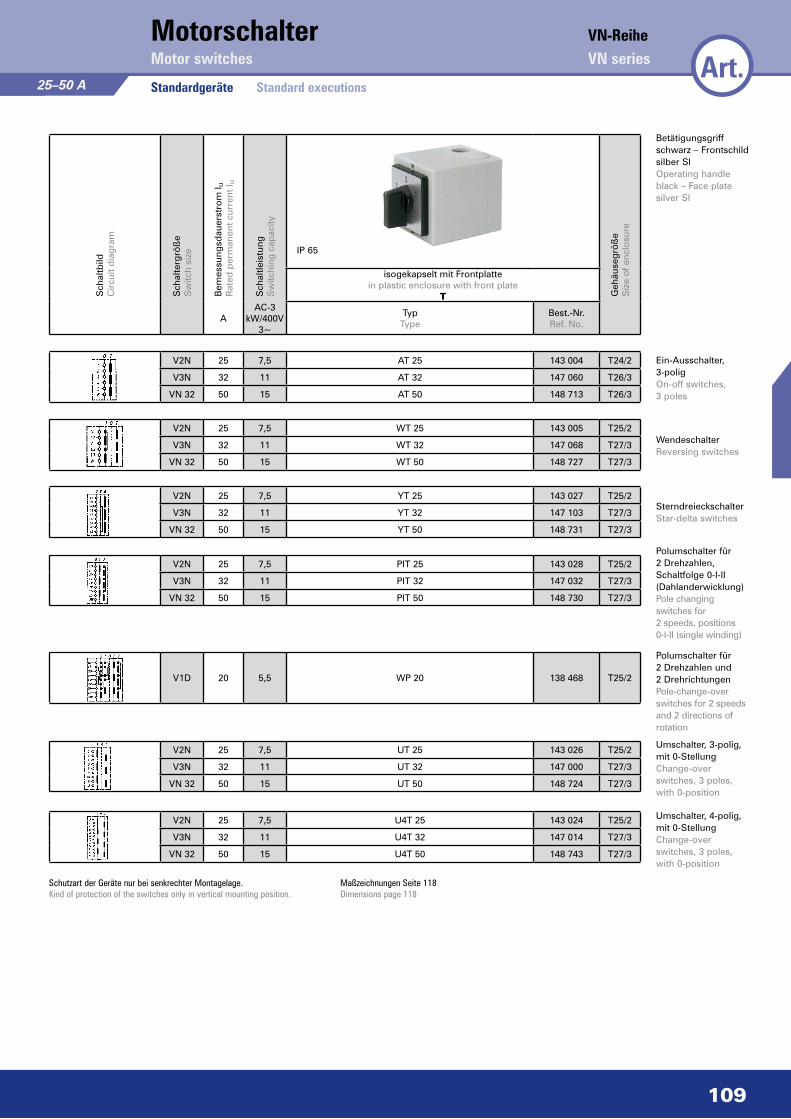
V1D 20 5,5 WP 20 138 468 T25/2
Motorschalter
Standardgeräte
V2N 25 7,5 PIT 25 143 028 T25/2
V3N 32 11 PIT 32 147 032 T27/3
VN 32 50 15 PIT 50 148 730 T27/3
IP 65
25–50 AS
chal
tbild
Cir
cuit
dia
gram
Sch
alte
rgrö
ße
Sw
itch
size
Bem
essu
ngsd
auer
stro
m I u
Rat
ed p
erm
anen
t cur
rent
I u
Sch
altle
istu
ngS
witc
hing
cap
acity
Geh
äuse
grö
ße
Siz
e o
f enc
losu
re
isogekapselt mit Frontplattein plastic enclosure with front plate
T
AAC-3
kW/400V 3~
Typ Type
Best.-Nr. Ref. No.
V2N 25 7,5 AT 25 143 004 T24/2
V3N 32 11 AT 32 147 060 T26/3
VN 32 50 15 AT 50 148 713 T26/3
V2N 25 7,5 WT 25 143 005 T25/2
V3N 32 11 WT 32 147 068 T27/3
VN 32 50 15 WT 50 148 727 T27/3
V2N 25 7,5 YT 25 143 027 T25/2
V3N 32 11 YT 32 147 103 T27/3
VN 32 50 15 YT 50 148 731 T27/3
Standard executionsArt.
VN-ReiheVN seriesMotor switches
Betätigungsgriff schwarz – Frontschild silber SIOperating handle black – Face plate silver SI
Ein-Ausschalter, 3-poligOn-off switches, 3 poles
WendeschalterReversing switches
SterndreieckschalterStar-delta switches
Polumschalter für 2 Dreh zahlen, Schalt folge 0-I-II (Dahlander wicklung)Pole changing switches for 2 speeds, positions 0-I-II (single winding)
Polumschalter für 2 Drehzahlen und 2 DrehrichtungenPole-change-over switches for 2 speeds and 2 directions of rotation
Schutzart der Geräte nur bei senkrechter Montagelage. Kind of protection of the switches only in vertical mounting position.
Maßzeichnungen Seite 118 Dimensions page 118
V2N 25 7,5 UT 25 143 026 T25/2
V3N 32 11 UT 32 147 000 T27/3
VN 32 50 15 UT 50 148 724 T27/3
V2N 25 7,5 U4T 25 143 024 T25/2
V3N 32 11 U4T 32 147 014 T27/3
VN 32 50 15 U4T 50 148 743 T27/3
Umschalter, 3-polig, mit 0-StellungChange-over switches, 3 poles, with 0-position
Umschalter, 4-polig, mit 0-StellungChange-over switches, 3 poles, with 0-position

110
Motor switchesMotorschalter
StandardgeräteArt.
Standard executions 25–400 A
Bem
essu
ngsd
auer
stro
m I u
Rat
ed p
erm
anen
t cur
rent
I u
Max
. Sch
altle
istu
ngM
ax. s
witc
hing
cap
acity
Geh
äuse
grö
ße
Siz
e o
f enc
losu
re
Geh
äuse
grö
ße
Siz
e o
f enc
losu
re
gussgekapselt in metal enclosure
isogekapseltin plastic enclosure
AAC-3
kW/400 V 3~
Typ Type
Best.-Nr. Ref. No.
TypType
Best.-Nr.Ref. No.
IP 65 IP 65
25 7,5 TUG 16 46 463 LG44/1 TUT 16 46 510 LT8/2
45 15 TUG 32 46 467 LG44/3 TUT 32 1) 46 511 LT60/2
63 22 TUG 50 302 423 LG48/2 – – –
100 30 TUG 80 46 475 LG59/5 – – –
150 55 VNUG 125 46 479 LG10/2 – – –
250 65 VNUG 200 155 395 LG14/3 – – –
400 200 VNUG 400 139 725 LG2/3 – – –
25 7,5 TU4G 16 46 440 LG44/1 TU4T 16 46 517 LT8/2
45 15 TU4G 32 46 522 LG44/3 TU4T 32 1) 46 518 LT60/2
63 22 TU4G 50 302 430 LG48/2 – – –
100 30 TU4G 80 152 500 LG59/5 – – –
150 55 TU4G 125 154 420 LG10/2 – – –
250 65 TU4G 200 155 380 LG14/3 – – –
400 200 TU4G 400 139 730 LG2/3 – – –
Umschalter für 2 Stromkreise,
3-polig, mit 0-StellungChange-over switches
for 2 circuits, 3 poles, with 0-position
Umschalter für 2 Stromkreise,
4-polig, mit 0-StellungChange-over
switches for 2 circuits, 4 poles, with
0-position
1) Schutzart IP 44 Kind of protection IP 44
Schutzart der Geräte nur bei senkrechter Montagelage.Kind of protection of the switches only in vertical mounting position.
Maßzeichnungen Seite 117-118Dimensions page 117-118
111
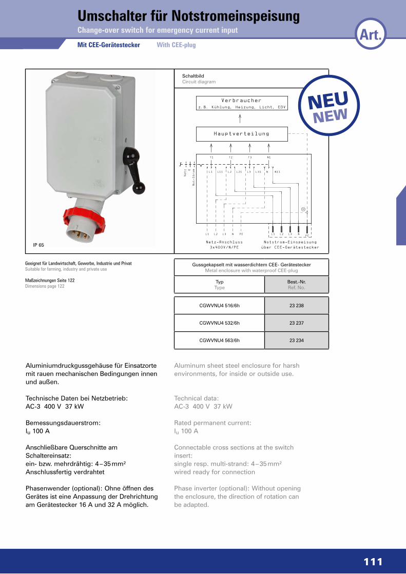
SchaltbildCircuit diagram
Gussgekapselt mit wasserdichtem CEE- GerätesteckerMetal enclosure with waterproof CEE-plug
Typ Type
Best.-Nr. Ref. No.
Umschalter für Notstromeinspeisung
Maßzeichnungen Seite 122 Dimensions page 122
CGWVNU4 516/6h 23 238
CGWVNU4 532/6h 23 237
CGWVNU4 563/6h 23 234
Change-over switch for emergency current input
Mit CEE-Gerätestecker With CEE-plug
�nderung
0
Datum Name
Datum
Bearb.
Gepr.
Norm
1
12.07.11
D.A.
O.G.
Kunde
Urspr.
2
Projekt
Ers.f.
3
AuftragsNr.
Ers.d.
4 5 6
Benennung
7
Notstromeinspeisung
VN80
8 9
Bl.
1 Bl.
1
Netz 0
NotStrom
z.B.K�hlung,Heizung,Licht,EDV
L1
L1
T1
L11
L2 L3
NetzAnschluss
3x400V/N/PE
L2
T2
N
L21
Verbraucher
Hauptverteilung
PE
L3
T3
L31 N
N1
N11
L1 L2 L3
NotstromEinspeisung
�berCEEGer„testecker
NPE
Art.
IP 65
Geeignet für Landwirt schaft, Gewerbe, Industrie und PrivatSuitable for farming, industry and private use
NeuNew
Aluminiumdruckgussgehäuse für Einsatzorte mit rauen mechanischen Bedingungen innen und außen.
Technische Daten bei Netzbetrieb: AC-3 400 V 37 kW
Bemessungsdauerstrom: Iu 100 A
Anschließbare Querschnitte am Schaltereinsatz: ein- bzw. mehrdrähtig: 4 – 35 mm² Anschlussfertig verdrahtet
Phasenwender (optional): Ohne öffnen des Gerätes ist eine Anpassung der Drehrichtung am Gerätestecker 16 A und 32 A möglich.
Aluminum sheet steel enclosure for harsh environments, for inside or outside use.
Technical data: AC-3 400 V 37 kW
Rated permanent current:Iu 100 A
Connectable cross sections at the switch insert:single resp. multi-strand: 4 – 35 mm²wired ready for connection
Phase inverter (optional): Without opening the enclosure, the direction of rotation can be adapted.

112
T 16 25 7,5 TA4GK 16/3S 46 453 LG2/2 M 20 2,5
T 32 45 15 TA4GK 32/3S 46 450 LG44/3 M 32 6
VN 50 63 22 VNA4GK50/3S 150 619 LG48/2 M 32 10
T 80 100 30 TA4GK 80/3S 1) 46 531 LG59/6 M 40 25
VN 125 150 55 VNA4GK 125/3S 1) 154 411 LG10/2 M 50 50
T 16 25 7,5 TAGK 16/3S 46 456 LG2/2 M 20 2,5
T 32 45 15 TAGK 32/3S 46 445 LG44/3 M 32 6
T 50 63 22 TAGK 50/3S 46 483 LG48/2 M 32 10
T 80 100 30 TAGK 80/3S 1) 46 480 LG59/6 M 40 25
VN 125 150 55 VNAGK 125/3S 1) 154 412 LG10/2 M 50 50
3-polig3-poles
IP 65
4-polig4 poles
3-polig + 1 S/1 Ö3 poles + 1 NO/1 NC
contact
6-polig + 1 S/1 Ö6 poles + 1 NO/1 NC
contact
6-polig6 poles
1) Schutzart IP 54 Kind of protection IP 54
Reparaturschalter
Guss-Gehäuse
Sch
altb
ildC
ircu
it d
iagr
am
Sch
alte
rgrö
ße
Sw
itch
size
Bem
essu
ngsd
auer
stro
m I u
Rat
ed p
erm
anen
t cur
rent
I u
Sch
altle
istu
ng (E
N 6
0947
-3)
Sw
itchi
ng c
apac
ity (E
N 6
0947
-3)
Geh
äuse
grö
ße
Siz
e o
f enc
losu
re
Kab
elei
nfüh
rung
sgrö
ße
Cab
le h
ole
dim
ensi
ons
max
. ans
chlie
ßb
are
Que
rsch
nitt
em
ax. c
onn
ecta
ble
cro
ssse
ctio
n
gussgekapselt mit Vorhängeschlossverriegelung in metal enclosure with interlocking
(customer provided)
A
AC-3kW/
400 V 3~
Typ Type
Best.-Nr. Ref. No.
mm2
V3L 25 7,5 V3LAGK/3S 151 132 LG2/2 M 20 2,5
VN 32 45 15 VNAGK 32/3S 148 701 LG44/3 M 32 6
VN 50 63 22 VNAGK 50/3S 150 595 LG48/4 M 32/M 16 10
VN 80 100 30 VNAGK 80/3S 1) 152 479 LG59/3 M 40/M 16 25
VN 125 150 55 VNAGK 125/3S 1) 154 421 LG10/4 M 50/M 16 50
NL400 400 200 3) NL 33/HS 400-LB2/3-EHD-MSI 4) 139 728 LB2/3 Ø 75/ M 16 2 x 150
NL630 630 2) 200 3) NL 33/HS 630-LB2/3-KV-MSI 4) 139 868 LB2/3 Ø 75/ M 16 2 x 150
V3L 25 7,5 V3LA6GK/3S 137 665 LG44/2 M 20 2,5
VN 32 45 15 VNA6GK 32/3S 148 698 LG44/3 M 32 6
VN 50 63 22 VNA6GK 50/3S 137 671 LG48/2 M 32 10
VN 80 100 30 VNA6GK 80/3S 1) 137 678 LG11/8 M 40 25
V3L 25 7,5 V3LA6GK/3S 137 661 LG44/6 M 20/M 16 2,5
VN 32 45 15 VNA6GK 32/3S 148 721 LG48/4 M 32/M 16 6
VN 50 63 22 VNA6GK 50/3S 137 669 LG48/4 M 32/M 16 10
VN 80 100 30 VNA6GK 80/3S 1) 137 680 LG59/3 M 40/M 16 25
VN 125 150 55 VNA6GK 125/3S 1) 137 699 LG10/4 M 50/M 16 50
Art. Maintenance switches
Metal enclosure 25–630 A
2) bei max. Anschlussquerschnitt by max. cross-section connection
3) AC-23A/AC-23B 4) Stahlblech-Gehäuse Lackierung RAL 7032 Sheet steel enclosure in RAL 7032 Maßzeichnungen Seite 39 Dimensions page 39 Weitere Schaltfunktionen auf Anfrage.
Other switching functions on request.
Maßzeichnungen Seite 117Dimensions page 117
113
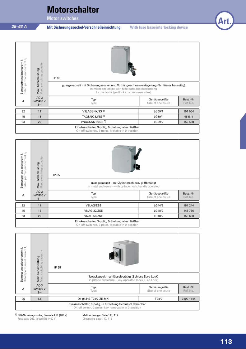
MotorschalterArt.Motor switches
Mit Sicherungssockel/Verschließeinrichtung
IP 65
IP 65
IP 65
5) D02-Sicherungssockel, Gewinde E18 (400 V) Fuse base D02, thread E18 (400 V)
Maßzeichnungen Seite 117, 119Dimensions page 117, 119
25–63 AB
emes
sung
sdau
erst
rom
I uR
ated
per
man
ent c
urre
nt I u
Max
. Sch
altle
istu
ngM
ax. s
witc
hing
cap
acity
gussgekapselt mit Sicherungssockel und Vorhängeschlossverriegelung (Schlösser bauseitig)in metal enclosure with fuse base and interlocking
for padlocks (padlocks by customer sites)
AAC-3
kW/400 V 3~
Typ Type
GehäusegrößeSize of enclosure
Best.-Nr. Ref. No.
Bem
essu
ngsd
auer
stro
m I u
Rat
ed p
erm
anen
t cur
rent
I u
Max
. Sch
altle
istu
ngM
ax. s
witc
hing
cap
acity
gussgekapselt – mit Zylinderschloss, griffbetätigtin metal enclosure – with cylinder lock, handle operated
AAC-3
kW/400 V 3~
Typ Type
GehäusegrößeSize of enclosure
Best.-Nr. Ref. No.
Bem
essu
ngsd
auer
stro
m I u
Rat
ed p
erm
anen
t cur
rent
I u
Max
. Sch
altle
istu
ngM
ax. s
witc
hing
cap
acity
isogekapselt – schlüsselbetätigt (Schloss Euro-Lock)in plastic enclosure – key-operated (Lock Euro-Lock)
AAC-3
kW/400 V 3~
Typ Type
GehäusegrößeSize of enclosure
Best.-Nr. Ref. No.
32 11 V3LAGSNK/3S 5) LG59/1 151 054
45 15 TAGSNK 32/3S 5) LG59/4 46 514
63 22 VNAGSNK 50/3S 5) LG59/2 150 588
Ein-Ausschalter, 3-polig, 0-Stellung abschließbarOn-off switches, 3 poles, lockable in 0-position
32 11 V3LAG/ZSE LG44/2 151 244
45 15 VNAG 32/ZSE LG48/2 148 766
63 22 VNAG 50/ZSE LG48/2 150 600
Ein-Ausschalter, 3-polig, 0-Stellung abschließbarOn-off switches, 3 poles, lockable in 0-position
25 5,5 D1 01/HS-T24/2-ZE-MXI T24/2 3199 1144
Ein-Ausschalter, 3-polig, in 0-Stellung Schlüssel abziehbarOn-off switch, 3 poles, key removable in 0-position
With fuse base/interlocking device

114
Spezialschalter
IP 65
IP 42
Schutzart der Geräte nur bei senkrechter Montagelage.Kind of protection of the switches only in vertical mounting position.
Maßzeichnungen Seite 120Dimensions page 120
25 A
Bem
essu
ngsd
auer
stro
m I u
Rat
ed p
erm
anen
t cur
rent
I u
Max
. Sch
altle
istu
ngM
ax. s
witc
hing
cap
acity
gussgekapselt – Isoknebelgriff stirnseitigin metal enclosure – plastic knob on front side
AAC-3
kW/400 V 3~
TypType
Best.-Nr. Ref. No.
Bem
essu
ngsd
auer
stro
m I u
Rat
ed p
erm
anen
t cur
rent
I u
Max
. Sch
altle
istu
ngM
ax. s
witc
hing
cap
acity
isogekapselt, für Untertischbefestigungin plastic enclosure, for under table fixing
AAC-3
kW/400 V 3~
TypType
Best.-Nr. Ref. No.
25 5,5 D1A-G2/3-B-MSX 3199 1089
Ein-Ausschalter, 3-polig, Gehäuse G2On-off switch, 3 poles, enclosure G2
25 5,5 B1N A-UT37/3-B-MSX 137 896
Ein-Ausschalter, 3-poligOn-off switch, 3 poles
MotorschalterArt. Motor switches
Special switches
IP 54
Bem
essu
ngsd
auer
stro
m I u
Rat
ed p
erm
anen
t cur
rent
I u
Max
. Sch
altle
istu
ngM
ax. s
witc
hing
cap
acity
isogekapselt, mit Signallampein plastic enclosure, with signal lamp
AAC-3
kW/400 V 3~
Typ Type
Best.-Nr. Ref. No.
25 7,5 V2N A/L-T24/2-B-MSI 143 268
Ein-Ausschalter, 3-poligOn-off switch, 3 poles

115
MotorschalterArt.Motor switches
IP 44
Mit CEE-Steckvorrichtung16-32 A
5-polig poles:3 P + N + 400 V, 50 Hz
5-polig poles:3 P + N + 400 V, 50 Hz
Bem
essu
ngsd
auer
stro
m I u
Rat
ed p
erm
anen
t cur
rent
I u
Max
. Sch
altle
istu
ngM
ax. s
witc
hing
cap
acity
Max
. Sch
altle
istu
ngM
ax. s
witc
hing
cap
acity
gussgekapselt mit CEE-Gerätesteckerin metal enclosure with CEE plug
isogekapselt mit CEE-Gerätesteckerin plastic enclosure with CEE plug
AAC-3
kW/400 V 3~
Typ Type
Best.-Nr. Ref. No.
AC-3kW/400 V
3~
TypType
Best.-Nr.Ref. No.
Bem
essu
ngsd
auer
stro
m I u
Rat
ed p
erm
anen
t cur
rent
I u
Max
. Sch
altle
istu
ngM
ax. s
witc
hing
cap
acity
abschaltbare CEE-Wandsteckdose, isogekapseltdisconnectible CEE wall mounting socket,
in plastic enclosure
AAC-3
kW/400 V 3~
Typ Type
Best.-Nr. Ref. No.
16 7,5 CGTNA 516/6h 46 654 5,5 CGD1 A 516/6h-CT8/2-S-GSX 3199 1142
32 15 CGTNA 532/6h 46 657 – – –
Ein-Ausschalter, 3-poligOn-off switches, 3 poles
Ein-Ausschalter, 3-poligOn-off switch, 3 poles
16 5,5 CD1AT 516/6h 3199 0957
32 11 CV3NAT 532/6h 146 970
Ein-Ausschalter, 3-polig On-off switch, 3 poles
16 5,5 CD1WT 516/6h 3199 0958
32 11 CV3NWT 532/6h 146 971
Wendeschalter, 3-polig Reversing switches, 3 poles
16 7,5 CGTNW 516/6h 46 655 5,5 CGD1 A 516P/6h-CT8/2-S-GSX 3199 1145
32 15 CGTNW 532/6h 46 658 – – –
Wendeschalter, 3-poligReversing switches, 3 poles
Ein-Ausschalter mit Stecker 16 A als PhasenwenderOn-off switch with plug 16 A as phase-inverter
16 7,5 CGTNY 516/6h 46 656 5,5 CGD1 W 516/6h-CT8/2-S-GSX 3199 1139
32 15 CGTNY 532/6h 46 659 – – –
SterndreieckschalterStar-delta switches
Wendeschalter, 3-poligReversing switch, 3 poles
IP 44 IP 44
With CEE plugs and sockets
Maßzeichnungen Seite 121-122Dimensions page 121-122
116
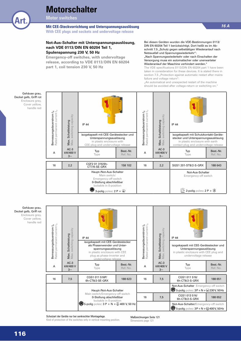
16 7,5CGS1 011 516P/
6h-CT8/2-SE-GRX188 623 16 7,5
CGS1 011 516/6h-CT8/2-S-GRX
188 651
Haupt-/Not-Aus-Schalter Main switch/Emergency-off switch
0-Stellung abschließbarlockable in 0-position
5-polig poles: 3 P + N + 400 V, 50 Hz
Not-Aus-Schalter Emergency-off switch
5-polig poles: 3 P + N + 230 V, 50 Hz
16 7,5CGS1 013 516/
6h-CT8/2-S-GRX188 652
Not-Aus-Schalter/Emergency-off switch
5-polig poles: 3 P + N + 400 V, 50 Hz
Mit CEE-Steckvorrichtung und UnterspannungsauslösungWith CEE plugs and sockets and undervoltage release
16 A
Not-Aus-Schalter mit Unterspannungsauslösung, nach VDE 0113/DIN EN 60204 Teil 1, Spulenspannung 230 V, 50 HzEmergency-off switches, with undervoltage release, according to VDE 0113/DIN EN 60204 part 1, coil tension 230 V, 50 Hz
Bei diesen Geräten wurden die VDE-Bestimmungen 0113/ DIN EN 60204 Teil 1 berücksichtigt. Dort heißt es im Ab- schnitt 7.5 „Schutz gegen selbsttätigen Wiederanlauf nach Netzausfall und Spannungswiederkehr“: „Nach Spannungswiederkehr oder nach Einschalten der Versorgung muss ein automatischer oder unerwarteter Wiederanlauf der Maschine verhindert werden.“ The VDE specifications 0113/DIN EN 60204 part 1 have been taken in consideration for these devices. It is stated there in section 7.5 „Protection against automatic restart after mains failure and voltage return“: „An automatical and unexpected restart of the machine should be avoided after voltage-return or switching on.“
Schutzart der Geräte nur bei senkrechter Montagelage.Kind of protection of the switches only in vertical mounting position.
Maßzeichnungen Seite 121Dimensions page 121
IP 44
Gehäuse grau, Deckel gelb, Griff rot
Enclosure grey, Cover yellow,
handle red
Gehäuse grau, Deckel gelb, Griff rot
Enclosure grey, Cover yellow,
handle red
Bem
essu
ngsd
auer
stro
m I u
Rat
ed p
erm
anen
t cur
rent
I u
Max
. Sch
altle
istu
ngM
ax. s
witc
hing
cap
acity
Bem
essu
ngsd
auer
stro
m I u
Rat
ed p
erm
anen
t cur
rent
I u
Max
. Sch
altle
istu
ngM
ax. s
witc
hing
cap
acity
isogekapselt mit CEE-Geräte stecker und Unterspannungsauslösung
in plastic enclosure with CEE plug and undervoltage release
isogekapselt mit Schutzkontakt-Geräte-stecker und Unterspannungsauslösung
in plastic enclosure with earth contact plug and undervoltage release
AAC-3
kW/400 V 3~
Typ Type
Best.-Nr. Ref. No.
AAC-3
kW/400 V 3~
TypType
Best.-Nr.Ref. No.
Bem
essu
ngsd
auer
stro
m I u
Rat
ed p
erm
anen
t cur
rent
I u
Max
. Sch
altle
istu
ngM
ax. s
witc
hing
cap
acity
Bem
essu
ngsd
auer
stro
m I u
Rat
ed p
erm
anen
t cur
rent
I u
Max
. Sch
altle
istu
ngM
ax. s
witc
hing
cap
acity
isogekapselt mit CEE-Gerätestecker als Phasenwender und Unter-
spannungsauslösung in plastic enclosure with CEE plug as phase-inverter and
undervoltage release
isogekapselt mit CEE-Gerätestecker und Unterspannungsauslösung
in plastic enclosure with CEE plug and undervoltage release
AAC-3
kW/400 V 3~
Typ Type
Best.-Nr. Ref. No.
AAC-3
kW/400 V 3~
TypType
Best.-Nr.Ref. No.
16 2,2 CGF2 01 316/6h- CT7/6-SE-GRX 158 102 16 2,2 SGS1 201-ST8/2-S-GRX 188 643
Haupt-/Not-Aus-Schalter Main switch/
Emergency-off switch0-Stellung abschließbar
lockable in 0-position
3-polig poles: 2 P +
Not-Aus-SchalterEmergency-off switch
2-polig poles: 2 P +
IP 44 IP 44
IP 44
MotorschalterArt. Motor switches
117
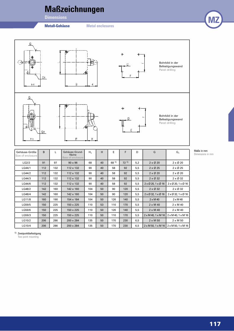
MZMaßzeichnungen
Metall-Gehäuse
Dimensions
Metal enclosures
Bohrbild in der BefestigungswandPanel drilling
Bohrbild in der BefestigungswandPanel drilling
1) Zweipunktbefestigung Two point mounting
Gehäuse-GrößeSize of enclosure
B L Gehäuse-Grund-fläche
Base of enclosure
H1 H E F D G G1
LG2/2 91 97 90 x 96 68 40 68 1) 72 1) 5,2 2 x Ø 20 2 x Ø 20
LG44/1 112 132 112 x 132 90 40 58 92 5,5 2 x Ø 25 2 x Ø 25
LG44/2 112 132 112 x 132 90 40 58 92 5,5 2 x Ø 20 2 x Ø 20
LG44/3 112 132 112 x 132 90 40 58 92 5,5 2 x Ø 32 2 x Ø 32
LG44/6 112 132 112 x 132 90 40 58 92 5,5 2 x Ø 20, 1 x Ø 16 2 x Ø 20, 1 x Ø 16
LG48/2 142 160 142 x 160 104 50 90 120 5,5 2 x Ø 32 2 x Ø 32
LG48/4 142 160 142 x 160 104 50 90 120 5,5 2 x Ø 32, 1 x Ø 16 2 x Ø 32, 1 x Ø 16
LG11/8 160 190 154 x 184 104 50 126 140 5,5 2 x M 40 2 x M 40
LG59/5 150 225 150 x 225 110 53 110 170 5,5 2 x M 40 2 x M 40
LG59/6 150 225 150 x 225 110 50 126 140 5,5 2 x M 40 2 x M 40
LG59/3 150 225 150 x 225 110 50 110 170 5,5 2 x M 40, 1 x M 16 2 x M 40, 1 x M 16
LG10/2 206 286 200 x 284 135 50 170 230 6,5 2 x M 50 2 x M 50
LG10/4 206 286 200 x 284 135 50 170 230 6,5 2 x M 50, 1 x M 16 2 x M 50, 1 x M 16
Maße in mmDimensions in mm
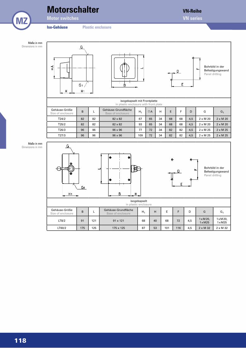
118
isogekapselt mit Frontplattein plastic enclosure with front plate
Gehäuse-GrößeSize of enclosure
B LGehäuse-Grundfläche
Base of enclosureH1 A H E F D G G1
T24/2 82 82 82 x 82 67 65 34 68 68 4,5 2 x M 20 2 x M 20
T25/2 82 82 82 x 82 93 65 34 68 68 4,5 2 x M 20 2 x M 20
T26/3 96 96 96 x 96 77 72 34 82 82 4,5 2 x M 25 2 x M 25
T27/3 96 96 96 x 96 109 72 34 82 82 4,5 2 x M 25 2 x M 25
Iso-Gehäuse
Maße in mmDimensions in mm
Maße in mmDimensions in mm
MZMotorschalterMotor switches
Plastic enclosure
VN-ReiheVN series
isogekapseltin plastic enclosure
Gehäuse-GrößeSize of enclosure
B LGehäuse-Grundfläche
Base of enclosureH1 H E F D G G1
LT8/2 91 121 91 x 121 68 40 68 72 4,51 x M 20,1 x M25
1 x M 20,1 x M25
LT60/2 175 125 175 x 125 87 53 101 116 4,5 2 x M 32 2 x M 32
Bohrbild in der BefestigungswandPanel drilling
Bohrbild in der BefestigungswandPanel drilling

119
Maßzeichnungen
Motorschalter mit Sicherungssockel/VerschließeinrichtungMotor switches with fuse base/interlocking device
Dimensions
Bohrbild in der BefestigungswandPanel drilling
Bohrbild in der BefestigungswandPanel drilling
Bohrbild in der BefestigungswandPanel drilling
Maße in mmDimensions in mm
Maße in mmDimensions in mm
Maße in mmDimensions in mm
gussgekapselt mit Sicherungssockel und Vorhängeschlossverriegelungin metal enclosure with fuse base and interlocking for padlocks
Gehäuse-GrößeSize of enclosure
B LGehäuse-Grundfläche
Base of enclosureH1 H E F D G G1
LG59/1 150 225 150 x 225 110 50 100 180 5,5 2 x M 25 2 x M 25
LG59/4 150 225 150 x 225 110 50 100 180 5,5 2 x M 32 2 x M 32
LG59/2 150 225 150 x 225 110 50 100 180 5,5 2x M32; 1 xM16 2x M32; 1 xM16
gussgekapselt mit Zylinderschloss, griffbetätigtin metal enclosure with cylinder lock, handle operated
Gehäuse-GrößeSize of enclosure
B LGehäuse-Grundfläche
Base of enclosureH1 H E F D G G1
LG44/2 112 132 112 x 132 90 53 58 92 5,5 2 x Ø 20 2 x Ø 20
LG48/2 142 160 142 x 160 104 53 90 120 5,5 2 x Ø 32 2 x Ø 32
isogekapselt mit Frontplattein plastic enclosure with front plate
Gehäuse-GrößeSize of enclosure
B LGehäuse-Grundfläche
Base of enclosureH1 A H E F D G G1
T24/2 82 82 82 x 82 67 48 37 68 68 4,5 2 x M 20 2 x M 20
MZ

120
isogekapselt mit Frontplattein plastic enclosure with front plate
Gehäuse-GrößeSize of enclosure
B LGehäuse-Grundfläche
Base of enclosureH1 A H E F D G G1
T24/2 82 82 82 x 82 67 48 34 68 68 4,5 2 x M 20 2 x M 20
isogekapselt, für Untertischbefestigungin plastic enclosure, for under table fixing
Gehäuse-GrößeSize of enclosure
B LGehäuse-Grundfläche
Base of enclosureH1 H H2 B1 L1 L2 E E1 D C K K1 J J1 G G1
UT37/3 72 100 72 x 100 53 17 18 95 104 50 82 85 6,2 25 28 46 32 40 Ø16 Ø16
Bohrbild in der BefestigungswandPanel drilling
Bohrbild in der BefestigungswandPanel drilling
Bohrungenverschlossen(ausbrechbar)Drillings closed(for breaking out)
Maße in mmDimensions in mm
Maße in mmDimensions in mm
Maße in mmDimensions in mm
gussgekapselt – Isoknebelgriff stirnseitigin metal enclosure – plastic knob on front side
Gehäuse-GrößeSize of enclosure
B LGehäuse-Grundfläche
Base of enclosureH1 H E F D G G1
G2/3 91 97 90 x 96 72 28 68 72 5,5 2 x Ø 20 2 x Ø 20
MZSpezialschalterSpecial switches
Maßzeichnungen Dimensions
121
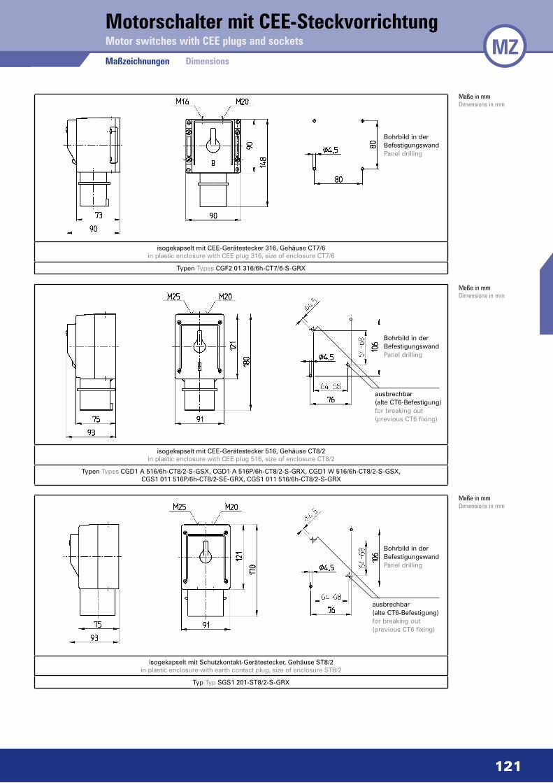
Motorschalter mit CEE-SteckvorrichtungMotor switches with CEE plugs and sockets MZ
Bohrbild in der BefestigungswandPanel drilling
Bohrbild in der BefestigungswandPanel drilling
ausbrechbar(alte CT6-Befestigung)for breaking out(previous CT6 fixing)
Bohrbild in der BefestigungswandPanel drilling
ausbrechbar(alte CT6-Befestigung)for breaking out(previous CT6 fixing)
Maße in mmDimensions in mm
Maße in mmDimensions in mm
Maße in mmDimensions in mm
isogekapselt mit CEE-Gerätestecker 316, Gehäuse CT7/6in plastic enclosure with CEE plug 316, size of enclosure CT7/6
Typen Types CGF2 01 316/6h-CT7/6-S-GRX
isogekapselt mit CEE-Gerätestecker 516, Gehäuse CT8/2in plastic enclosure with CEE plug 516, size of enclosure CT8/2
Typen Types CGD1 A 516/6h-CT8/2-S-GSX, CGD1 A 516P/6h-CT8/2-S-GRX, CGD1 W 516/6h-CT8/2-S-GSX, CGS1 011 516P/6h-CT8/2-SE-GRX, CGS1 011 516/6h-CT8/2-S-GRX
isogekapselt mit Schutzkontakt-Gerätestecker, Gehäuse ST8/2in plastic enclosure with earth contact plug, size of enclosure ST8/2
Typ Typ SGS1 201-ST8/2-S-GRX
Maßzeichnungen Dimensions
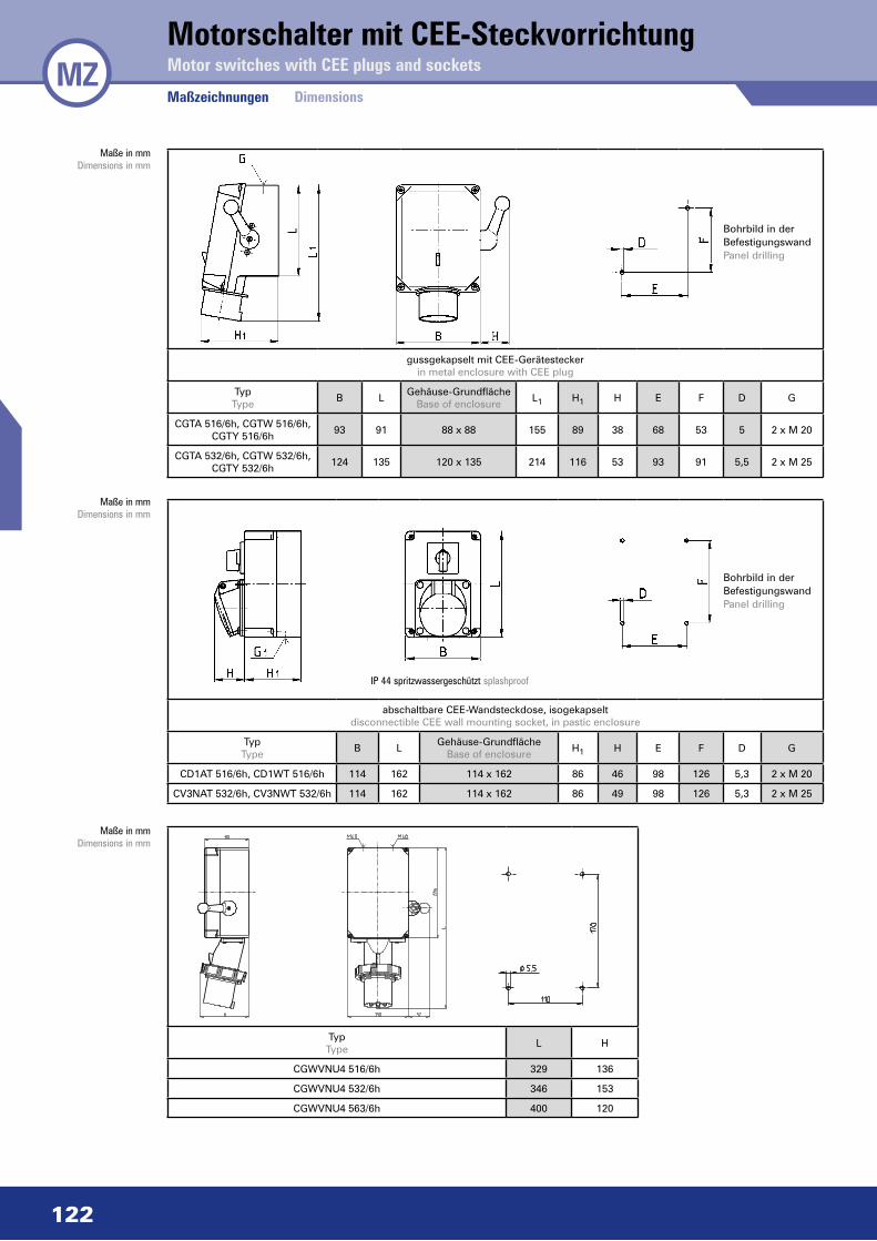
Bohrbild in der BefestigungswandPanel drilling
Bohrbild in der BefestigungswandPanel drilling
Maße in mmDimensions in mm
Maße in mmDimensions in mm
Maße in mmDimensions in mm
IP 44 spritzwassergeschützt splashproof
gussgekapselt mit CEE-Gerätesteckerin metal enclosure with CEE plug
TypType
B LGehäuse-Grundfläche
Base of enclosureL1 H1 H E F D G
CGTA 516/6h, CGTW 516/6h, CGTY 516/6h
93 91 88 x 88 155 89 38 68 53 5 2 x M 20
CGTA 532/6h, CGTW 532/6h, CGTY 532/6h
124 135 120 x 135 214 116 53 93 91 5,5 2 x M 25
abschaltbare CEE-Wandsteckdose, isogekapseltdisconnectible CEE wall mounting socket, in pastic enclosure
TypType
B LGehäuse-Grundfläche
Base of enclosureH1 H E F D G
CD1AT 516/6h, CD1WT 516/6h 114 162 114 x 162 86 46 98 126 5,3 2 x M 20
CV3NAT 532/6h, CV3NWT 532/6h 114 162 114 x 162 86 49 98 126 5,3 2 x M 25
TypType
L H
CGWVNU4 516/6h 329 136
CGWVNU4 532/6h 346 153
CGWVNU4 563/6h 400 120
MZMotorschalter mit CEE-SteckvorrichtungMotor switches with CEE plugs and sockets
Maßzeichnungen Dimensions
122


![Low Voltage Switches Enclosed switches - eOT …...2015/09/02 · Plastic enclosed switches 3-pole manual motor contollers Amp Weight/ rating Handle Handle Auxiliary unit [A] type](https://img.pdfslide.net/doc/110x75/5f6c7df914311b0294135e40/low-voltage-switches-enclosed-switches-eot-20150902-plastic-enclosed.jpg)