Embed Size (px)
Citation preview

HANBAY Inc MPA Operators Manual V3.20 ______________________________________________________________________________________
Page 1
MPA Operators Manual Contents: Page
1.0 Hanbay Multi Position Miniature Electric Actuator (MPA) 3
1.1 Features 3 1.2 Valves and Torque 3
1.2.1 Valve Connections 4 2.0 MPA Technical Specifications 5 3.0 Setting Up the MPA 6
3.1 Mounting the Valve with the Mounting Plate onto the Actuator 6 3.2 Attaching the Valve-Actuator Assembly 7
3.2.1 Panel Mount 7 3.2.2 Multiple Valves on Panel 8 3.2.3 Individual Assembly Mount 9
3.3 Setting the configuration dip switches 10 3.3.1 Serial Communications Board 10 3.3.2 Digital Communication Board 12
3.4 Stepper Motor Connection to Electronics Board 12 3.5 Cable to Electronics Board 13 3.6 Power Connection 14 3.7 TTL and Continuous (4 .. 20 mA & 1.. 5V) Signal Connection 15 3.8 Serial Port Connection 16
4.0 Operating the MPA with Digital Signals 17
4.1 Initializing the Digital Communications MPA 18 4.2 Digital Communications MPA Error Messages 18
5.0 Serial Communication 19 5.1 The HANBAY Protocol 19
5.1.1 Hardwire Addressing 19 5.1.2 Data Transfer Format 20 5.1.3 Initializing the Serial Communications MPA 21 5.1.4 Programming Examples for MPA 22 5.1.5 Discrete Valve Positioning Commands 23
6.0 Continuous Valve Positioning MPA Commands (Serial Comm) 26
6.1 Programming Examples for micro stepping MPA 30 7.0 Continuous Valve Positioning MPA (4 .. 20 mA & 1.. 5V Signal) 31
7.1 Speed and torque setting for needle valve actuation 31 7.2 Setting of number of turns for needle valve actuation 32 7.3 Setting Continuous Actuators for needle valves 33 7.4 General remarks for needle valve actuation 33
8.0 Extra Power Settings 36 9.0 Ordering Information 37 10.0 Main dimensions with some valves 38 11.0 Contact Information 39

HANBAY Inc MPA Operators Manual V3.20 ______________________________________________________________________________________
Page 2
List of tables: Page Table 1.1 Switching Time Voltage & Torque 3 Table 1.2 Part Number Valve Mounting Plate 4 Table 3.1 MPA Panel Mount, Multiple Valves 8 Table 3.2 MPA Individual Mount 9 Table 3.3 Marking of board version (Serial = SE3.X or Digital = TTL3.X) 10 Table 3.4 Valve Name Setting for Serial Communication Board 11 Table 3.5 Valve Speed Setting for Digital Communication Board 12 Table 3.6 Stepper Motor Connections 12 Table 3.7 Power Connections 14 Table 3.8 TTL Signal Connections 15 Table 3.9 Continuous Signal Connections (4 .. 20mA & 1.. 5V) 15 Table 3.10 Serial Port Connections 16 Table 4.1 Controlling MPA with Digital Signals 17 Table 4.2 Error message analysis for MPA with Digital Signals 18 Table 5.1 Protocol Commands 19 Table 5.2 Data Transfer Format 20 Table 5.3 Initiate Communication with MPA 21 Table 5.4 Move to Center Position and ask for status 22 Table 5.5 Discrete valve positioning commands and responses to Inquiries 23 Table 5.6 MPA Discrete Positioning Responses 24 Table 5.7 MPA Discrete Positions and moving directions 24 Table 5.8 Valve Speed Serial Communication with 4 at end of part number 25 Table 5.9 Valve Speed Serial Communication with 5 at end of part number 25 Table 6.1 MPA full number of micro steps (range of micro steps) 26 Table 6.2 MPA Micro-Step Commands 27 Table 6.3 MPA Micro-Step Responses 29 Table 6.4 Move to Center Position and ask for status 30 Table 7.11 Multi turn Valve Speed for Cont service MPA02 regular version 31 Table 7.12 Multi turn Valve Speed for Cont service MPA02-R68 version 31 Table 7.2 Multi turn Valve number of turns input 32 Table 7.4.1 N/O – N/C Settings for CO3.X PC Board 34 Table 7.4.2 N/O Settings for CO3.X PC Board 35 Table 7.4.3 N/C Settings for CO3.X PC Board 35 Table 8.1 Extra Power settings 36 Table 9.1 Ordering 37 Table 10.1 Main Dimensions 38

HANBAY Inc MPA Operators Manual V3.20 ______________________________________________________________________________________
Page 3
1.0 Hanbay Multi Position Miniature Electric Actuator (MPA) The Hanbay MPA has been designed for easy configuration in automation of small valves. Typical applications include: - Laboratory automation PC controlled valve actuation - OEM automated sampling and measuring devices, all applications that need automated valve control - Small valve control in production environment 1.1 Features - Small size 1.1 lbs weight - High accuracy positioning - Multi position L - Center – R – Opposite Center - TTL position feedback - AC / DC 12-24V - Failed operation feedback - Panel mount - High torque for small devices - TTL inputs for positioning - Ideal for small valves etc. - RS485 / RS232 Control capability - Multi actuator projects - Daisy Chain Operation - Needle Valve Control - Position Memory - Multi Turn Application 1.2 Valves and Torque Essentially any valve or application that can be satisfied by the torque and times shown in this table, may be driven by the MPA (DC Torques with D – C jumper in “D” position, see 3.7) :
Time for 1/4 turn
Power Supply
Output Torque @ end speed
Pullout Torque @ start speed
5.0 sec 12 VDC @ 1.0 A 24 in-lbs 2.7 Nm 35 in-lbs 4.0 Nm 3.2 sec 12 VDC @ 0.7 A 16 in-lbs 1.8 Nm 35 in-lbs 4.0 Nm 5.0 sec 16 VDC @ 1.5 A 37 in-lbs 4.2 Nm 43 in-lbs 4.9 Nm 2.5 sec 16 VDC @ 0.8 A 24 in-lbs 2.7 Nm 43 in-lbs 4.9 Nm 3.0 sec 24 VDC @ 1.3 A 34 in-lbs 3.8 Nm 43 in-lbs 4.9 Nm 2.0 sec 24 VDC @ 1.1 A 27 in-lbs 3.1 Nm 43 in-lbs 4.9 Nm 1.7 sec 24 VDC @ 1.0 A 24 in-lbs 2.7 Nm 43 in-lbs 4.9 Nm 4.7 sec 12 VAC @ 1.5 A 25 in-lbs 2.8 Nm 25 in-lbs 2.8 Nm 3.2 sec 12 VAC @ 1.2 A 19 in-lbs 2.1 Nm 25 in-lbs 2.8 Nm 5.0 sec 16 VAC @ 2.2 A 37 in-lbs 4.2 Nm 40 in-lbs 4.5 Nm 2.5 sec 16 VAC @ 1.5 A 23 in-lbs 2.6 Nm 40 in-lbs 4.5 Nm 2.5 sec 24 VAC @ 2.1 A 33 in-lbs 3.7 Nm 43 in-lbs 4.9 Nm 1.6 sec 24 VAC @ 1.8 A 30 in-lbs 3.4 Nm 43 in-lbs 4.9 Nm 1.3 sec 24 VAC @ 1.6 A 20 in-lbs 2.3 Nm 43 in-lbs 4.9 Nm 9.5 sec 24 VAC @ 2.1 A 122 in-lbs 13.9 Nm 161 in-lbs 18.4 Nm
Table 1.1 Switching Time Voltage & Torque - The Multiturn version, has a different gear ratio and delivers 1/3 of the torque shown above at 3 times the speed. (see Table 5.8 and 5.9 for speed settings serial MPA and Table 3.5 for digital MPA) - The reducer version e.g.: MPAx6 has a reducer and increases torque by a factor of 3.75; it also reduces the speed by the same factor and is available only for Center +/- ¼ turn versions.

HANBAY Inc MPA Operators Manual V3.20 ______________________________________________________________________________________
Page 4
1.2.1 Valve Connections To find the part number for your valves and valve adaptation plates, please use the following order number schematic: * use 6 at end of MPA part number, multiply torque and turning time by 3.75 (see table 5.8) Please call us for torque requirements and suitability of our MPA actuator for your valve Table 1.2 Part Number Valve Mounting Plate
0 TTL Digital Communication1 Serial Communication, discrete positions
1 Mechanical Position Indicator Option2 Manual Mechanical Positioning Option
Multi Position Actuator
4 Micro-step, Serial, 4’706 steps / revolution5 Micro-step, Serial, 1’568 steps / revolution
M A P
6 Micro-step, Serial, 17’647 steps / revolution for reducer version only
Analog Com. 4 .. 20mA or 1 .. 5V 23RPM 2
Analog Com. isolated 8 RPM3i
0 No Valve or Mounting Plate 1 Mounting Plate Only 3 Valve with Mounting Plate, Mounted Assembly
- -
Valve Manufacturers Valve Part Number
Analog Com. isolated 23RPM2i Analog Com. 4 .. 20mA or 1 .. 5V 8 RPM 3

HANBAY Inc MPA Operators Manual V3.20 ______________________________________________________________________________________
Page 5
2.0 MPA Technical Specifications Operating and Programming
The MPA can be computer controlled via RS485 interface or via TTL digital I/O signals. RS485 will allow distances of up to 1200m (4000ft) from the controlling source.
A converter from RS232 to RS485 is available from HANBAY. The MPA can move forward and backward and has an optical/mechanical position feedback for the discrete center and end positions or, in the case of the multi turn application, for confirmation of motion.
Positioning Accuracy and Resolution Accuracy: Discrete Positioning 1/4 turn, 1/2 turn, 1/3 turn : +/- 0.5 deg Discrete Positioning increments of 3.75 deg: +/- 0.5 deg Resolution: Discrete Positioning Resolution: +/- 0.32 deg Multi turn Micro stepping Resolution: +/- 0.25 deg Multi turn System Backlash (8P): 0.9 deg Controls The RS485 MPA Default Baud Rate is 9600. The MPA may also be accessed via RS-232 by means of an RS485 converter. RS232 to RS485 converters are available from Hanbay. TTL Controls 2 Inputs, 2 Outputs Continuous Controls 1 Inputs 4 .. 20 mA or 1 .. 5 V MPA Actuator Packaging Sealed Package, Aluminum anodized.
Sealing rating is watertight, not submersible. Size: 99 mm (3.9in) x 70mm (2.75in) x 44mm (1.7in) Weight: 600gr (1.1lbs) (Actuator only, no valve) Power Requirements Will function properly on 12-24 V AC or DC. The Isolated board versions will require 12-30 VDC supply. Please refer to table 1.1 for current requirements 110V or 220V to 24 V Transformers for one or multiple units are available from Hanbay

HANBAY Inc MPA Operators Manual V3.20 ______________________________________________________________________________________
Page 6
3.0 Setting up the MPA 3.1 Mounting the Valve with the Mounting Plate onto the Actuator
1. Insert valve in mounting plate and attach and tighten nut
2. Mount valve lever with set screw for securing screw, use locktite
3. Locate driving pins in actuator, and carefully insert valve with valve lever to go between the two pins
3 Attach mounting plate to actuator
4 It’s as easy as it looks...

HANBAY Inc MPA Operators Manual V3.20 ______________________________________________________________________________________
Page 7
3.2 Attaching the Valve-Actuator Assembly 3.2.1 Panel Mount
1. Panel
Panel cut out diameter is 49.6 mm (1.951”) Panel thickness is 1.6mm (1/16”) - 3.2mm (1/8”) Facilitate your job by using knock out tools. E.G.: Slug-Buster Punches from: Greenlee-Textron Rockford IL 815 397 7070 Part No.: UPC78-3310-31966 Cat No.: 7211BB-1-1/2
2. Insert valve under panel and
3. mount valve on actuator; the actuator is now attached to the panel by the groove in the mounting plate

HANBAY Inc MPA Operators Manual V3.20 ______________________________________________________________________________________
Page 8
3.2.2 Multiple Valves on Panel You can mount the MPA in multiples on a panel and create neat arrangements, keeping electric parts on one side and all the fluid parts on the other. Plan just enough space for electrical cable entries, and also think how to access the fluid connections and their connecting tubes or hoses. This is an example of how several MPA’s could be mounted on a panel: Table 3.1 MPA Panel Mount, Multiple Valves
Electric side of panel Cable Entry
Fluid side of panel Valve fluid connections
Panel cut out diameter is 1.951” Panel thickness is 1/16 - 1/8”
Panel

HANBAY Inc MPA Operators Manual V3.20 ______________________________________________________________________________________
Page 9
3.2.3 Individual Assembly Mount This is just an example of how an MPA could mount on its separate mounting holes. The possibilities are endless. (Mounting bracket usually supplied by user): Table 3.2 MPA Individual Mount
Mounting Bracket 1/8” thick
Attachment Screws 8-32 x 1/2”
User’s mounting surface
Valve fluid connections
Cable Entry

HANBAY Inc MPA Operators Manual V3.20 ______________________________________________________________________________________
Page 10
3.3 Setting the configuration dip switches Remove the cover of the actuator with the four screws and locate the 10 position dip switch. (The CO3.x boards for 4..20mA communication, have a 12 position DIP switch instead) See also Table 3.7 for location of DIP switch To set a dip switch (or to turn it on), the connection must be established by carefully toggling the switch to it’s on position.
To ensure the operation that you expect, set the dip switches the following way: 3.3.1 Serial Communications Board The Serial Board is identified by the marking SE3.X
Table 3.3 Marking of board version (Serial = SE3.X or Digital = TT3.X or Continuous = CO3.X or Continuous isolated signal = COi3.X)
P2
4 3 2 1
1 2 3 4 5 6 7 P1
P2
SE3.1
HANBAY Inc MPA Operators Manual V3.20 ______________________________________________________________________________________
Page 11
If you are using the serial communications board, the Dip switches (Dip's) are used to determine which valve number the valve shall become for your communications.
Use the following table to determine the settings that you need: Dip4
Dip3
Dip2
Dip 1
Address # ASCII Code
Alpha numeric
Hex Code
ASCII Code
Alpha numeric
Hex Code
MPA as a receiver of signals(MPA receives from
Controlling Computer)
MPA as a sender of signals (MPA responds to Controlling
Computer) 0 0 0 0 1 std 97 a 61H 65 A 41H 0 0 0 1 2 98 b 62H 66 B 42H 0 0 1 0 3 99 c 63H 67 C 43H 0 0 1 1 4 100 d 64H 68 D 44H 0 1 0 0 5 101 e 65H 69 E 45H 0 1 0 1 6 102 f 66H 70 F 46H 0 1 1 0 7 103 g 67H 71 G 47H 0 1 1 1 8 104 h 68H 72 H 48H 1 0 0 0 9 105 i 69H 73 I 49H 1 0 0 1 10 106 j 6AH 74 J 4AH 1 0 1 0 11 107 k 6BH 75 K 4BH 1 0 1 1 12 108 l 6CH 76 L 4CH 1 1 0 0 13 109 m 6DH 77 M 4DH 1 1 0 1 14 110 n 6EH 78 N 4EH 1 1 1 0 15 111 o 6FH 79 O 4FH 1 1 1 1 16 112 p 70H 80 P 50H
Address of Controlling Computer 96 ‘ 60H
Table 3.4 Valve Name Setting for Serial Communication Board
IMPORTANT: you do NOT need to remove the PC board from the MPA to work on the settings of the Dip’s

HANBAY Inc MPA Operators Manual V3.20 ______________________________________________________________________________________
Page 12
3.3.2 Digital Communication Board The Digital Board is identified by the marking TTX.X
If you are using the digital communications board, the DIP's are used to determine the speed of the movement of the actuator.
Time for 1/4 turn
Power Supply
Output Torque @ end speed
Pullout Torque @ start speed
Dip3
Dip2
Dip1
Equivalentto V(HEX)
5.0 sec 12 VDC @ 1.0 A 24 in-lbs 2.7 Nm 35 in-lbs 4.0 Nm 0 0 0 7840 3.2 sec 12 VDC @ 0.7 A 16 in-lbs 1.8 Nm 35 in-lbs 4.0 Nm 0 1 0 7828 5.0 sec 16 VDC @ 1.5 A 37 in-lbs 4.2 Nm 43 in-lbs 4.9 Nm 0 0 0 7840 2.5 sec 16 VDC @ 0.8 A 24 in-lbs 2.7 Nm 43 in-lbs 4.9 Nm 0 0 1 781E 3.0 sec 24 VDC @ 1.3 A 34 in-lbs 3.8 Nm 43 in-lbs 4.9 Nm 0 1 1 7822 2.0 sec 24 VDC @ 1.1 A 27 in-lbs 3.1 Nm 43 in-lbs 4.9 Nm 1 0 0 7816 4.7 sec 12 VAC @ 1.5 A 25 in-lbs 2.8 Nm 25 in-lbs 2.8 Nm 1 0 1 4040 5.0 sec 16 VAC @ 2.2 A 37 in-lbs 4.2 Nm 40 in-lbs 4.5 Nm 0 0 0 7840 2.5 sec 16 VAC @ 1.5 A 23 in-lbs 2.6 Nm 40 in-lbs 4.5 Nm 0 0 1 781E 2.5 sec 24 VAC @ 2.1 A 33 in-lbs 3.7 Nm 43 in-lbs 4.9 Nm 1 1 0 7820 1.6 sec 24 VAC @ 1.8 A 30 in-lbs 3.4 Nm 43 in-lbs 4.9 Nm 1 1 1 7814
Table 3.5 Valve Speed Setting for Digital Communication Board 3.4 Stepper Motor Connection to Electronics Board The stepper motor is connected to the small, vertical connector P2 on the PC board. The connection schematic is as follows:
Table 3.6 Stepper Motor Connections
NOTE: MPA’s with 3 or 5 at the end of the part number have the yellow wire connected to P2/1 and the black wire to P2/2
P2
P1
4 3 2 1
1 2 3 4 5 6 7 STEPPER MOTOR
red gry yel
blk

HANBAY Inc MPA Operators Manual V3.20 ______________________________________________________________________________________
Page 13
3.5 Cable to Electronics Board Select a connection cable with the number of leads corresponding to your application (see table 3.7, 3.8 and 3.9). The GND for power and signals can be put on the same wire. The liquid Tight Strain Relief on the base of the actuator is designed to accommodate a cable of O.D. 2.5 - 6.5mm (0.10 - 0.26in). Be sure to not use a cable with an OD that is bigger than this! IMPORTANT NOTE: you have to connect a solid ground to the system. Do not use your com-port Gnd for this purpose.
1.- Remove the liquid tight fitting from the actuator casing and insert the cable into it. 2.- The cable has to be stripped of its jacket for 2 inches (50mm) and the wires need 1/8” (3mm) stripped ends
3.- Bend the wires so that insertion becomes easy 4.- Insert the cable into the actuator base
5.- Put the liquid tight fitting back and tighten (lightly with tool) 6.- Hand tighten the liquid tight fitting to establish seal
7.- Connect wires according to your application (see tables 3.7, 3.8, 3.9) 8.- Mount actuator cover and tighten 4 screws
HANBAY Inc MPA Operators Manual V3.20 ______________________________________________________________________________________
Page 14
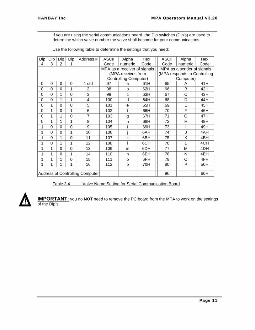
3.6 Power Connection
For all the boards with AC power conversion on board, the power connections have to be made the same way (the COi isolated 4..20mA board comes in DC only and does not have the position 7 connection) :
Table 3.7 Power Connections Important Note for DC voltage applications only: To use the system on DC voltages only, you may solder the DC Solder Points together on the back of the board (marked SP1). This will add some 10-20% of power to the system and may be necessary for some DC applications (N/A on the isolated board). This connects the + side of the rectifier bridge with one of the AC input sides. DO NOT close this SP1 point for AC applications
IMPORTANT NOTE: you have to connect a solid ground to the system. Do not use your com-port Gnd or controller Gnd only for this purpose. Damage to the instrument, or computer might result if you do.
DIP switch Selector
DC only Solder Point
(N/A in isolated board)
P2
4 3 2 1
1 2 3 4 5 6 7 P1
GND V+ DC Voltages
P2
4 3 2 1
1 2 3 4 5 6 7 P1
GND V~ V~AC Voltages
HANBAY Inc MPA Operators Manual V3.20 ______________________________________________________________________________________
Page 15
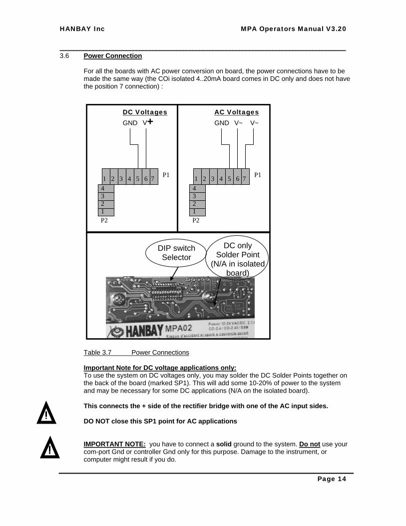
3.7 TTL and Continuous (4 .. 20 mA & 1.. 5V) Signal Connection
Table 3.8 TTL Signal Connections
Table 3.9 Continuous Signal Connections (4 .. 20mA & 1.. 5V)
P2
4 3 2 1
3 3 4 5 6 7 P1
- +
MPA
SIGNAL GND MPA
RES GND
NOTE 3: connect supply voltage According to Table 3.7. Set MPA speed depending on which voltage you use: See table 3.5 and table 7.1
NOTE 2: Signal Gnd is NOT ISOLATED from Power Gnd. If Signal Gnd is different from Power Gnd, use HANBAY MPA02i or MPA03i actuator.
P2
4 3 2 1
1 2 3 4 5 6 7 P1
Input #1
TTL I/O Signals
Input #2
Output #2 Output #1
MPA Actuator
USER SUPPLIED
GND
GND
2
1
1
2
RL (max drive current 2.5mA)
External I/O device supplied by user < 1mA
MPA
NOTE 1: For 1 ..5 V Signal Remove 250 ohm resistor R16, Located in the RES area of the board (or just cut one lead of it)
4 .. 20mA Signal User powered

HANBAY Inc MPA Operators Manual V3.20 ______________________________________________________________________________________
Page 16
3.8 Serial Port Connection
Table 3.10 Serial Port Connections IMPORTANT NOTE: Daisy chaining needs to be done as shown in this table.
Do not connect in star configuration.
TD(A) TD(B) RD(A) RD(B) SG +12VDC Gnd
P2
4 3 2 1
1 2 3 4 5 6 7 P1
RS485 A
Serial and Daisy Chain Connections
The farthest or only Actuator in a chain needs a 470 Ohm Resistor between Pin1 and Pin2
470 Ohm 1/8W
Actuator #1
P2
4 3 2 1
1 2 3 4 5 6 7 P1
Actuator #2
P2
4 3 2 1
1 2 3 4 5 6 7 P1
Actuator #n (16 maximum)
RS485 B
RS232 to RS485 Converter
B & B Electronics Model 485PTBRSerial Port RS232
An external power supply is required, use a source that can supply 12 to 16VDC @ 40mA
Note: mount this resistor only for long chains of actuators

HANBAY Inc MPA Operators Manual V3.20 ______________________________________________________________________________________
Page 17
4.0 Operating the MPA with Digital Signals The MPA has 2 digital inputs and two digital outputs. Use the TTL Communication ordering option if you wish to use the MPA for positioning a ¼ turn valve (2 position valve) or a ¼ left and ¼ turn right valve (3 position valve) of any description like an L-shaped or T-shaped 3-way valve. 4 position valves may also be actuated with this version of the MPA. Also use this option for any other 3-position or 2-position valves that may run at 60 degree angles instead of 90 degrees. Turning angles, other than 90 degrees require a mention on ordering, because the position detection disk will need to be customized for that. Any other application that can be satisfied with the torque and speed as given in Table 1.1 can be connected and accommodated with this actuator. The simple connections to digital inputs and outputs, as shown in paragraph 3.7 lets you control and verify this system as follows: (Input and Output is denominated as seen from MPA)
Input#1 (Pin 1)
Input#2 (Pin 2)
Action taken
Low Low Moves to or remains in opposite to center position High Low Moves to or remains in left position Low High Moves to or remains in right position High High Moves to or remains in center position
The feedback of the MPA is as follows: Output#1
(Pin 3) Output#2
(Pin 4) Meaning
Low Low MPA is in position as requested by Input#1 and Input#2 High Low MPA is in motion and about to (or trying to) reach the requested
position Low High MPA has timed out in trying to reach requested position
I.E.: MPA has tried to turn for 25 sec and did not reach the requested position. The motor stops now. You may retry to reach any position again by setting Input#1 and Input#2. I.E.: toggle Input #1 low for a few milliseconds and back to high if this is was what you where asking for initially. If the problem persists, you have to trouble shoot the unit.
Table 4.1 Controlling MPA with Digital Signals

HANBAY Inc MPA Operators Manual V3.20 ______________________________________________________________________________________
Page 18
4.1 Initializing the Digital Communications MPA The MPA is initialized (reset) the moment when you power it up. You do not need to reset the unit on start up. On initialization (or reset), the Digital MPA will move until it detects the position as requested by the setting of Input #1 and Input #2. As it is moving, Output#1 turns high. The moment it finds the requested position, Output#1 turns low. 4.2 Digital Communications MPA Error Messages
Interpretation of MPA digital feedback messages Output#1 Output#2 Short Detail Description
Low Low is in position as requested by Input#1 and Input#2
MPA is passive and in the requested position
High Low is in motion and trying to reach the requested position
MPA is moving; this state will last until: 1.- MPA reaches the end point requested by
Input#1 and Input#2; in this case Output#1 goes back to “low”
2.- MPA times out; after trying to reach the requested position for 25 sec, the motor stops and the Output#1 remains “high” and the error Output #2 is also set.
Low High Unit has created an error message
ERROR: MPA has created an error message, it was unable to reach the requested position. ACTION: Retry by requesting other (previous) position and then the requested position, if problem persists, reset power and retry again, if problem still persists, proceed to troubleshooting valve (E.G.: check for obstruction in flow path etc.), valve connection and unit failure, verify electric connections, fuse on electronic board (with multi meter), check for destroyed parts on electronic board, check for jammed gears etc.
Table 4.2 Error message analysis for MPA with Digital Signals

HANBAY Inc MPA Operators Manual V3.20 ______________________________________________________________________________________
Page 19
5.0 Operating the MPA with Serial Communication 5.1 The HANBAY Protocol The required communication hardware format is compatible with the industry standard RS232. All the pins on the DB9 connector must be connected. Data Format: Interface: RS485 or RS232 (with Converter as shown in Table 3.10) Baud Rate: 9600 standard
Parity: None Data Bits: 8 Stop Bits: 1 Flow Control: None Important Note: In the advanced settings in Windows turn off the FIFO Buffer option: Settings > Control Panel > System > Com Port COM1 > Port Settings > Advanced > remove tick in FIFO buffers >save and exit.
As a basis for accessing the RS485 device, you should use the sample program supplied by HANBAY. The RS485 device, which may be plugged into any serial port, requires some advanced timing to communicate correctly with MPA. The HANBAY Protocol uses three basic control characters: Notation Name Hex ASCII Description
<CR> Carriage Return 0DH 13 A control character that ends the text of an instruction
<OK> or 0
Transmission Received no error in command string
30H 48 A control character transmitted by a receiving device indicating an affirmative response to the transmitting device
<TER> or 1
Transmission Received with error in command string
31H 49 A control character transmitted by a receiving device indicating a non-affirmative response to the transmitting device
Table 5.1 Protocol Commands 5.1.1 Hardwire Addressing Each MPA unit connected on a chain as shown in Table 3.10 needs to be given a unique address by setting the dip switches as shown in Table 3.4 To communicate with only one MPA, the standard open position of all DIP’s is usually used, resulting in address 1 (or “a”) for the unit
HANBAY Inc MPA Operators Manual V3.20 ______________________________________________________________________________________
Page 20
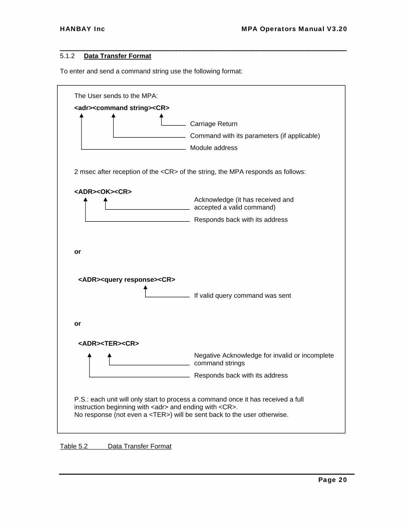
5.1.2 Data Transfer Format To enter and send a command string use the following format: Table 5.2 Data Transfer Format
<adr><command string><CR> Carriage Return Command with its parameters (if applicable) Module address
2 msec after reception of the <CR> of the string, the MPA responds as follows:
<ADR><OK><CR>
Responds back with its address Acknowledge (it has received and accepted a valid command)
<ADR><query response><CR> If valid query command was sent
or
<ADR><TER><CR> Negative Acknowledge for invalid or incomplete command strings
or
P.S.: each unit will only start to process a command once it has received a full instruction beginning with <adr> and ending with <CR>. No response (not even a <TER>) will be sent back to the user otherwise.
Responds back with its address
The User sends to the MPA:

HANBAY Inc MPA Operators Manual V3.20 ______________________________________________________________________________________
Page 21
5.1.3 Initializing the Serial Communications MPA The MPA is initialized the moment when you power it up. From that time on it will wait for commands. The Serial Communications MPA will not do any movement in either direction until it receives instructions. Table 5.3 Initiate Communication with MPA
aQ<CR> Carriage Return Address MPA No “1” (see Table 3.4)
Check out response of unit (programming example)
MPA responds as follows:
A@1=<CR>
Responds back with its address Respond to the Inquiry command by sending back position and action (3 digits) Last Digit “=” means it’s there (see table 5.6)
No Response or
A1<CR>
or
In this case, there is no unit connected to the line with this address number or the full command string incl. <CR> has not been received. Check 1.- Power to unit 2.- SP settings (see Table 3.4) 3.- Syntax of communication request 4.- Address (see Table 3.4)
Negative acknowledge (MPA saw the address and something after the address that is bad syntax)
User sends the following string to MPA:
Inquiry Command

HANBAY Inc MPA Operators Manual V3.20 ______________________________________________________________________________________
Page 22
5.1.4 Programming Examples for MPA The following two commands show how to move the MPA to center position and how to ask for the status on the MPA Table 5.4 Move to Center Position and ask for status
dA1<CR> Command “move to center” (see Table 5.5) Address MPA No “4” (see Table 3.4)
Move MPA to left position (programming example)
MPA responds as follows:
D0<CR>
Responds back with its address Acknowledge (it has received and accepted a valid command)
User sends the following string to MPA:
dQ<CR>
Address MPA No “4” (see Table 3.4)
Ask MPA for status (programming example)
MPA responds as follows:
D@1=<CR>
Responds back with its address MPA is at position “Y”
User sends the following string to MPA:
Command “status” (see Table 5.6)
“Present Pos = 1” (see Table 5.6) “Actuator is at requested position” (see Table 5.6)

HANBAY Inc MPA Operators Manual V3.20 ______________________________________________________________________________________
Page 23
5.1.5 Discrete Valve Positioning Commands This command set is used with the three or four position sensing encoder on the MPA. Its applications are 2, 3 and 4 way valves which typically have a “center” position and two end positions, one called “left” and the other called “right”.
MPA Discrete Positioning Commands (1 at end of Part Nr.)
Note: the user sends the parameters in 1, 2 or 4 digit Hex Code followed by <CR> (do not suppress leading zeros). All the turning directions are as viewed onto the top of the appliance connected to the MPA. Com-mand
Parameter Range
Action performed
V XXXX
MPA speed setting, see tables 5.8, 5.9 and 6.1 This number goes into an EEPROM memory and needs to be sent to the actuator only once.
P none Ping command: it simply responds with presence of MPA addressed A n = 0 .. 3
Moves to position {parameter} in the shortest way from the present position. Will move from 2 to 0 through 1. See table 5.7 for discrete positions and directions. Note: On start up and reset (power failure), the MPA is never “@” at a discrete position; this is regardless of whether the shut down occurred in the middle of a movement or at a fixed position. The detection of position is only indicating in which quadrant (see Table 5.7) you are. To properly recover from this, at start up, you can first ask for which quadrant you are in with <adr>Q. If you get say >3= you could move the shortest way to 0 or 3 with <adr>A0 or <adr>A3. Then you get the @ again and then it’s going to move as described above. Another way, of course, is, to keep track of positions and movements in your software and to use the L and R commands below.
L n = 0 .. 3 Moves from the present position to {parameter} position turning left only (in counter clock direction, opens the tap).
N n= 01 - FF Moves {n} micro steps (relative from present position) in counter clock direction (opens the tap). FF micro steps is equivalent to 19.507 degrees
R n = 0 .. 3 Moves from the present position to {parameter} position turning right only (in clock direction, closes the tap).
M n= 01 - FF Moves {n} micro steps (relative from present position) in clock direction (closes the tap). FF micro steps is equivalent to 19.507 degrees
S n=0 n=1
Not silent will respond and acknowledge all the commands. Silent: does not confirm commands but will still respond to the Q command
X none Stops whatever the MPA is doing Table 5.5 Discrete valve positioning commands and responses to Inquiries

HANBAY Inc MPA Operators Manual V3.20 ______________________________________________________________________________________
Page 24
MPA Discrete Positioning Responses Note: the MPA always sends the response to the inquiry in the format: <ADR>XYZ<CR> Inquiry Response Detailed description of response
Q XYZ X = “>” MPA is between position Y and Y+1 ; if Y = 3 then Y+1 = 0 X = “@” MPA is at position Y Y = “0” .. “3” discrete positions of actuator. See table 5.7 for discrete positions. Z = “=” actuator is at the requested position Z = “-” actuator is moving in the negative direction (clock wise) Z = “+” actuator is moving in the positive direction (counter clock wise) Z = “?” an error occurred, the MPA could not reach the requested position
Table 5.6 MPA Discrete Positioning Responses
HANBAY Inc MPA Operators Manual V3.20 ______________________________________________________________________________________
Page 25
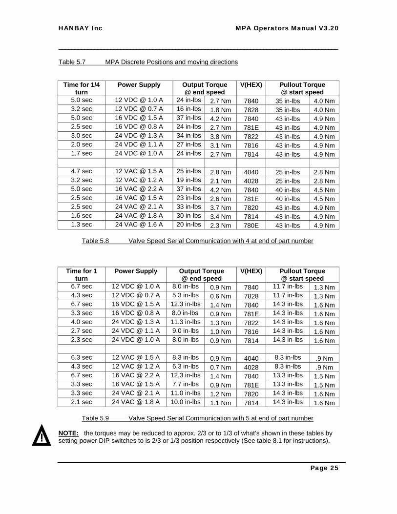
Table 5.7 MPA Discrete Positions and moving directions
Time for 1/4 turn
Power Supply
Output Torque @ end speed
V(HEX)
Pullout Torque @ start speed
5.0 sec 12 VDC @ 1.0 A 24 in-lbs 2.7 Nm 7840 35 in-lbs 4.0 Nm 3.2 sec 12 VDC @ 0.7 A 16 in-lbs 1.8 Nm 7828 35 in-lbs 4.0 Nm 5.0 sec 16 VDC @ 1.5 A 37 in-lbs 4.2 Nm 7840 43 in-lbs 4.9 Nm 2.5 sec 16 VDC @ 0.8 A 24 in-lbs 2.7 Nm 781E 43 in-lbs 4.9 Nm 3.0 sec 24 VDC @ 1.3 A 34 in-lbs 3.8 Nm 7822 43 in-lbs 4.9 Nm 2.0 sec 24 VDC @ 1.1 A 27 in-lbs 3.1 Nm 7816 43 in-lbs 4.9 Nm 1.7 sec 24 VDC @ 1.0 A 24 in-lbs 2.7 Nm 7814 43 in-lbs 4.9 Nm
4.7 sec 12 VAC @ 1.5 A 25 in-lbs 2.8 Nm 4040 25 in-lbs 2.8 Nm 3.2 sec 12 VAC @ 1.2 A 19 in-lbs 2.1 Nm 4028 25 in-lbs 2.8 Nm 5.0 sec 16 VAC @ 2.2 A 37 in-lbs 4.2 Nm 7840 40 in-lbs 4.5 Nm 2.5 sec 16 VAC @ 1.5 A 23 in-lbs 2.6 Nm 781E 40 in-lbs 4.5 Nm 2.5 sec 24 VAC @ 2.1 A 33 in-lbs 3.7 Nm 7820 43 in-lbs 4.9 Nm 1.6 sec 24 VAC @ 1.8 A 30 in-lbs 3.4 Nm 7814 43 in-lbs 4.9 Nm 1.3 sec 24 VAC @ 1.6 A 20 in-lbs 2.3 Nm 780E 43 in-lbs 4.9 Nm
Table 5.8 Valve Speed Serial Communication with 4 at end of part number
Time for 1 turn
Power Supply
Output Torque @ end speed
V(HEX)
Pullout Torque @ start speed
6.7 sec 12 VDC @ 1.0 A 8.0 in-lbs 0.9 Nm 7840 11.7 in-lbs 1.3 Nm 4.3 sec 12 VDC @ 0.7 A 5.3 in-lbs 0.6 Nm 7828 11.7 in-lbs 1.3 Nm 6.7 sec 16 VDC @ 1.5 A 12.3 in-lbs 1.4 Nm 7840 14.3 in-lbs 1.6 Nm 3.3 sec 16 VDC @ 0.8 A 8.0 in-lbs 0.9 Nm 781E 14.3 in-lbs 1.6 Nm 4.0 sec 24 VDC @ 1.3 A 11.3 in-lbs 1.3 Nm 7822 14.3 in-lbs 1.6 Nm 2.7 sec 24 VDC @ 1.1 A 9.0 in-lbs 1.0 Nm 7816 14.3 in-lbs 1.6 Nm 2.3 sec 24 VDC @ 1.0 A 8.0 in-lbs 0.9 Nm 7814 14.3 in-lbs 1.6 Nm
6.3 sec 12 VAC @ 1.5 A 8.3 in-lbs 0.9 Nm 4040 8.3 in-lbs .9 Nm 4.3 sec 12 VAC @ 1.2 A 6.3 in-lbs 0.7 Nm 4028 8.3 in-lbs .9 Nm 6.7 sec 16 VAC @ 2.2 A 12.3 in-lbs 1.4 Nm 7840 13.3 in-lbs 1.5 Nm 3.3 sec 16 VAC @ 1.5 A 7.7 in-lbs 0.9 Nm 781E 13.3 in-lbs 1.5 Nm 3.3 sec 24 VAC @ 2.1 A 11.0 in-lbs 1.2 Nm 7820 14.3 in-lbs 1.6 Nm 2.1 sec 24 VAC @ 1.8 A 10.0 in-lbs 1.1 Nm 7814 14.3 in-lbs 1.6 Nm
Table 5.9 Valve Speed Serial Communication with 5 at end of part number
NOTE: the torques may be reduced to approx. 2/3 or to 1/3 of what’s shown in these tables by setting power DIP switches to is 2/3 or 1/3 position respectively (See table 8.1 for instructions).
HANBAY Inc MPA Operators Manual V3.20 ______________________________________________________________________________________
Page 26
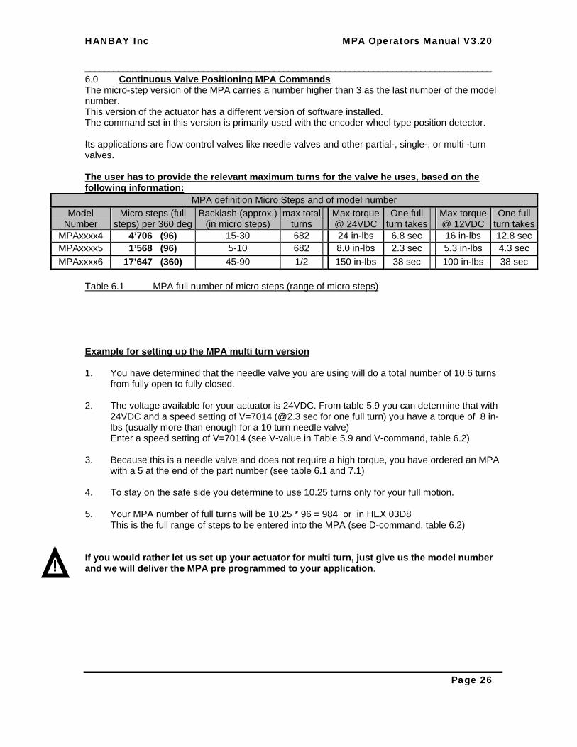
6.0 Continuous Valve Positioning MPA Commands The micro-step version of the MPA carries a number higher than 3 as the last number of the model number. This version of the actuator has a different version of software installed. The command set in this version is primarily used with the encoder wheel type position detector. Its applications are flow control valves like needle valves and other partial-, single-, or multi -turn valves. The user has to provide the relevant maximum turns for the valve he uses, based on the following information:
MPA definition Micro Steps and of model number Model
Number Micro steps (full
steps) per 360 deg Backlash (approx.)
(in micro steps) max total
turns Max torque @ 24VDC
One full turn takes
Max torque @ 12VDC
One full turn takes
MPAxxxx4 4’706 (96) 15-30 682 24 in-lbs 6.8 sec 16 in-lbs 12.8 secMPAxxxx5 1’568 (96) 5-10 682 8.0 in-lbs 2.3 sec 5.3 in-lbs 4.3 sec MPAxxxx6 17’647 (360) 45-90 1/2 150 in-lbs 38 sec 100 in-lbs 38 sec
Table 6.1 MPA full number of micro steps (range of micro steps) Example for setting up the MPA multi turn version 1. You have determined that the needle valve you are using will do a total number of 10.6 turns
from fully open to fully closed. 2. The voltage available for your actuator is 24VDC. From table 5.9 you can determine that with
24VDC and a speed setting of V=7014 (@2.3 sec for one full turn) you have a torque of 8 in-lbs (usually more than enough for a 10 turn needle valve) Enter a speed setting of V=7014 (see V-value in Table 5.9 and V-command, table 6.2)
3. Because this is a needle valve and does not require a high torque, you have ordered an MPA
with a 5 at the end of the part number (see table 6.1 and 7.1) 4. To stay on the safe side you determine to use 10.25 turns only for your full motion. 5. Your MPA number of full turns will be 10.25 * 96 = 984 or in HEX 03D8 This is the full range of steps to be entered into the MPA (see D-command, table 6.2) If you would rather let us set up your actuator for multi turn, just give us the model number and we will deliver the MPA pre programmed to your application.

HANBAY Inc MPA Operators Manual V3.20 ______________________________________________________________________________________
Page 27
MPA Micro-Step Commands (4, 5 or 6 at end of Part Nr.) Note: the user sends the parameters in1, 2 or 4 digit Hex Code followed by <CR> (do not suppress leading zeros). All the turning directions are as viewed onto the top of the appliance connected to the MPA. Com-mand
Parameter Range
Action performed
V XXXX
MPA speed setting, see tables 5.8, 5.9 and 6.1 (see table 5.8, 5.9 and 6.1 for available torques) This number goes into an EEPROM memory and needs to be sent to the actuator only once.
C none moves to or remains in fully closed position, initiates the fully closed position to Q=”0000=” Note1: If C is not used then Q = “8000” at start up. (This is useful in applications that require relative movement from the start-up position) Note2: If you wish to close the needle valve until it stops on the seat, it is always recommended to use the “C” command to do so. This way, slight discrepancies due to valve seat wear, mechanical precision etc. will be taken out and you can be certain that the valve is actually closed.
D 0001 to FFFF
(1/96 turn to
682 turns)
Enter total number of full steps (range of turns) into the system. The way this is done is, you take the full range of turns you want the system to use (this should usually be not more than what the valve is actually capable of doing) then you multiply this number by 96 per turn and send this number to the MPA.This number goes into an EEPROM memory and needs to be sent to the actuator only once.
P none Ping command: it simply responds with presence of MPA addressed A 0000 .. D moves to absolute position {parameter} in the relevant direction from the
present position. Caution: If D was not defined it is assumed at 1000 Note: D is never used or looked at unless the actuator was zeroed with “C” or centered with “H”
L n= 01 – FF
moves in counter clock direction (opens the tap). Will move by (n * 3.75) deg (full steps) until it detects and confirms the requested movement on the encoder wheel. This command is cumulative (it will add or subtract the number of steps requested together and execute, even if sent before execution is finished) If the user requests an end position past the “D” setting, this command will stop at “D” and will not attempt to move beyond. (no error message created)
N n= 01 - FF
Moves {n} micro steps (relative from present position) in counter clock direction (opens the tap). For micro steps per full turn refer to table 6.1. This command is not cumulative. It will only move from present position. If the user requests an end position past the “D” setting, this command will go past “D”; every subsequent L, R or A command though, that would have an end position beyond “D” will return the actuator to position “D”
Table 6.2 MPA Micro-Step Commands (continued on next page)

HANBAY Inc MPA Operators Manual V3.20 ______________________________________________________________________________________
Page 28
R n=
01 - FF moves in clock direction (closes the tap). Will move by (n* 3.75) deg (full steps) until it detects and confirms the requested movement on the encoder wheel. This command is cumulative If the user requests an end position below “0000”, this command will stop at “0000” and will not attempt to move beyond. (no error message created)
M n= 01 - FF
Moves {n} micro steps (relative from present position) in clock direction (closes the tap). For micro steps per full turn refer to table 6.1. This command is not cumulative. It will only move from present position. If the user requests an end position below “0000”, this command will attempt to move below “0000”; whether or not it succeeds to go below “0000” it will set the obtained end position as (new) “0000”.
S n=0 n=1
Not silent will respond and acknowledge all the commands. Silent: does not confirm commands but will still respond to the Q command
X none Stops whatever the MPA is doing H none Used to move to center position of reducer version MPA.
The outside track of the encoder rising edge finds “H”. The allowed travel distance will then be D/2 for the “R” command, taking it to 0000 and D/2 for the “L” command taking it to D. D needs to be entered for this command. Note1: D can not be more than 00BC (2 * 94 degrees) otherwise, this command can not work properly. Note2: for the setup of the high torque reducer version of the MPA (I.E.:part Nr. MPAxSTx6), proceed as follows: 1.- mount actuator 2.- <adr>D00B4 (180 degrees 3.- <adr>C (full close and set to 0 4.- <adr>L5C 5.- adjust the raising edge of the outside run of the encoder wheel to the right photo detector on the board. (the empty outside run is on the board side) 6.- <adr>R05 7.- <adr>H Note: the MPA should only run very short now; you are ready to go8.- for full left position use <adr>L5A<enter> (90 degrees to the left, CCW) 9.- for full right position use <adr>R5A<enter> (90 degrees to the right, CW) 10.- for the center position always use <adr>H<enter> Note3: if you use N and M in this application then: 1.- if you are at 0000 and use <adr>NXX this will bring you into “negative territory” and will reset the position counter to “0000”; this can only go on until you hit the hard stop in the gear reducer attachment. To find the real precise center again, you can just simply run <adr>H. No such resetting takes place at the top end. 2.- use of N and M may cause the subsequent H command to search in the wrong direction at first. In the worst case it will stop at the bottom of the range and emit a error message <adr>Q will respond <ADR>0000?. The H command has to be re run again and it will find the center properly. CAUTION: This command is in the same software version as all the other micro step commands. DO NOT ATTEMPT TO USE this command if your MPA does not have a 6 at the end of the part number
Table 6.2 MPA Micro-Step Commands

HANBAY Inc MPA Operators Manual V3.20 ______________________________________________________________________________________
Page 29
MPA Micro-Step Responses Note: the MPA always sends the response to the inquiry in the format: <ADR>XXXXY<CR> Inquiry Response Detailed description of response
Q XXXXY “XXXX” = absolute position of actuator in 3.75 deg steps on the output shaft (equals to 96 {60H} steps per full turn) “Y” = “+” actuator is moving in the positive direction (counter clock wise) “Y” = “-” actuator is moving in the negative direction (clock wise) “Y” = “=” actuator is at the requested position “Y” = “?” an error occurred, the MPA could not reach the requested position
Table 6.3 MPA Micro-Step Responses

HANBAY Inc MPA Operators Manual V3.20 ______________________________________________________________________________________
Page 30
6.1 Programming Examples for micro stepping MPA Table 6.4 Move to Center Position and ask for status
fM7D<CR> Command “Left 125 micro steps” (see Table 6.2) Address MPA No “6” (see Table 3.4)
Move MPA 125 steps in the Left turn direction (programming example for micro stepping version)
MPA responds as follows:
F0<CR>
Responds back with its address Acknowledge (it has received and accepted a valid command)
User sends the following string to MPA:
fQ<CR>
Address MPA No “6” (see Table 3.4)
Ask MPA for status
MPA responds as follows:
D030A+<CR>
Responds back with its address
User sends the following string to MPA:
Command “Inquiry” (see Table 5.5 and Table 6.3)
Responds: Y= “+” “MPA presently moves in Positive direction”
Responds: X= 030A “present position; not micro steps but 3.75 deg intervals”
For all responses compare Table 6.3
A few moments later the response to the inquiry should be as follows:
D030F=<CR>
Responds back with its address
Responds: Y= “=” “MPA presently moves in Positive direction”
Responds: X= 030F “present position in 3.75 deg intervals”

HANBAY Inc MPA Operators Manual V3.20 ______________________________________________________________________________________
Page 31
7.0 Continuous Valve Positioning MPA (4 .. 20 mA & 1.. 5V Signal Connection) 7.1 Speed and torque setting for needle valve actuation The continuous signal Board is identified by the marking CO3.X or COi3.x
To locate the DIP selector switch, refer to Table 3 All torque values are in in-lbs. To obtain Nm from in-lbs torque, divide the in-lbs value by 9. Ex.: 11.7 in-lbs / 9 = 1.3 Nm The second number, where present, is the thrust in lbs (1 lb thrust = 4.5N) for linear version of actuator NA means: don’t use actuator in this range
Time for 1 turn
1/3 Power 12VDC 24VDC
2/3 Power 12VDC 24VDC
3/3 Power 12VDC 24VDC Dip1 Dip2 Dip3
Equivalentto V(HEX)
9.0 sec 11 11 18 18 16 24 OFF OFF OFF 6060 7.6 sec 10 11 16 18 14 22 OFF OFF ON 6050 6.2 sec 9 10 14 18 14 22 OFF ON OFF 6040 4.8 sec 8 10 14 18 11 16 OFF ON ON 6030 3.2 sec 8 10 14 18 11 16 ON OFF OFF 6020 2.8 sec 8 10 12 16 NA NA ON OFF ON 601A 2.6 sec 8 10 12 14 NA NA ON ON OFF 6018 2.5 sec 4 4 NA NA NA NA ON ON ON 6016
Table 7.11 Multi turn Valve Torque & Speed for Continuous service MPA02 regular Version This second table below is valid for the “tuned down” version R68 of the MPA02 and MPL02 actuator. This version has been created to actuate delicate, low torque valves. .
Time for 1 turn
1/3 Power 12VDC 24VDC
2/3 Power 12VDC 24VDC
3/3 Power 12VDC 24VDC Dip1 Dip2 Dip3
Equivalent to V(HEX)
9.0 sec 2.4 / NA 3.0 / NA 12 14 / 77 16 18 / 99 OFF OFF OFF 6060 7.6 sec 2.6 / NA 3.3 / NA 10 12 / 77 12 12 / 99 OFF OFF ON 6050 6.2 sec 2.8 / NA 3.4 / NA 7 9 / 70 10 10 / 96 OFF ON OFF 6040 4.8 sec 2.8 / NA 3.4 / NA 6 8 / 66 8 8 / 92 OFF ON ON 6030 3.2 sec 2.5 / NA 3.2 / NA 5 6 / 66 6 6 / 88 ON OFF OFF 6020 2.8 sec 1.6 / NA 2.0 / NA 4 5 / 52 NA NA / 88 ON OFF ON 601A 2.6 sec 1.3 / NA 1.5 / NA 3 3 / 48 NA NA / 74 ON ON OFF 6018 2.5 sec 1.1 /NA 1.5 / NA NA NA / 37 NA NA / 61 ON ON ON 6016
Table 7.12 Multi turn Valve Torque & Speed for Continuous service MPA02-R68 Version
Actuator with 3 at the end of the part number will produce a torque of 3 times of what’s shown in the table above, at a speed of 1/3 of what’s shown in the table above. The valve that’s actuated by this actuator shall not require more toque than the number as shown in the tables above to operate. To deal with sticking at the beginning of the movement the MPA is equipped with an acceleration at the beginning of each move it makes, which results in an increased torque to “pull” the valve out of it’s steady state.

HANBAY Inc MPA Operators Manual V3.20 ______________________________________________________________________________________
Page 32
7.2 Setting of number of turns for needle valve actuation
To set the number of turns for the full range of 4..20mA or 1..5V signal of the continuous needle valve applications, use the table below: “1” = “ON” “0” = “OFF”
Dip8
Dip7
Dip6
Dip5
Dip4
Number of turns for full range
Dip8
Dip7
Dip6
Dip5
Dip4
Number of turns for full range
1 1 1 1 1 reserved 0 1 1 1 1 16 1 1 1 1 0 1 0 1 1 1 0 17 1 1 1 0 1 2 0 1 1 0 1 18 1 1 1 0 0 3 0 1 1 0 0 19 1 1 0 1 1 4 0 1 0 1 1 20 1 1 0 1 0 5 0 1 0 1 0 21 1 1 0 0 1 6 0 1 0 0 1 22 1 1 0 0 0 7 0 1 0 0 0 23 1 0 1 1 1 8 0 0 1 1 1 24 1 0 1 1 0 9 0 0 1 1 0 25 1 0 1 0 1 10 0 0 1 0 1 26 1 0 1 0 0 11 0 0 1 0 0 27 1 0 0 1 1 12 0 0 0 1 1 28 1 0 0 1 0 13 0 0 0 1 0 29 1 0 0 0 1 14 0 0 0 0 1 30 1 0 0 0 0 15 0 0 0 0 0 31
Table 7.2 Multi turn Valve number of turns input Dip switch 8 (shaded in above table) is used as shown, to adjust the number of turns in the signal isolated version of the COi series PC board In the CO series PC board, dip switch 8 is used for power settings (See table 8.1) For CO series boards only (not COi), to set the equivalent of DIP8 in the above table to “0”, cut this SP8 trace here

HANBAY Inc MPA Operators Manual V3.20 ______________________________________________________________________________________
Page 33
7.3 Setting Continuous Actuators for needle valves
To ensure proper functioning and to improve the performance of the MPAx2, MPAx3, MPAx4 and MPAx5 model, the following measures can be taken: 1.- If you need open and close action only, based on a digital signal, see 7.5 (this does not apply to the digital control models MPAx4 and MPAx5) 2.- If you have a “sticky” valve that will be hard to open after it has been shut, apply the “B” setting as described in Table 8.1 3.- if you are unable to move the valve in any direction, try the 66% or 100% power setting as described in Table 8.1 4.- If your power is 12 - 24VDC, then the system will receive approx 10-20% more power by closing the DC gap solder point SP1 as described in Table 3.7
7.4 General remarks for needle valve actuation
The full range of the analog input is representing 4 .. 20 mA or 1 .. 5V depending on the choice of the input resistor position as described in table 3.9.
The standard setting is for 4 .. 20 mA..
At start up, the valve shuts, then reads the input and then immediately sets to the position requested by the analog input.
Example: If you have chosen a full range of turns of 4 as per the table 7.2 above, then your actuator is going to use 4 turns as 100 % of your positioning range; so for instance, a signal of 25% (which is 8mA) will set the valve to 1 turn open. The input is read continuously and the valve is set according to the input. To be certain that the valve shuts against the seal (until it mechanically stops on the seal) and to deal with slight signal transmission inaccuracies, any setting below 4.16mA is considered fully closed. In other words, the valve will really only start to lift off it’s seal at 4.165mA. Any time that the signal request falls below 4.165mA, the valve performs a “shut 100% against the seal” and “ redefine the shut position” operation, exactly as it does on first start up. It is often a good idea to reduce the power of the actuator by setting the DIP switch position to either 1/3 or 2/3 power to obtain the reduced 1/3 or 2/3 of the torques available. (See table 8.1 for detailed instructions) This way, the seat of the metering or needle valve is exposed to reduced closing torques. Compare also table 3.5, 5.8, 5.9 and 7.1 and their notes.

HANBAY Inc MPA Operators Manual V3.20 ______________________________________________________________________________________
Page 34
7.5 Settings for open close actuation of multi turn applications
It is possible to modify the standard CO3.x or Coi3.x PC board to have it act for N/C or N/O operation.
Table 7.4.1 N/O – N/C Settings for COX.X PC Board
2.- Remove R16
View from DIP switch side
3.- mount a 10K resistor between these 2 pads
1.- Cut this trace

HANBAY Inc MPA Operators Manual V3.20 ______________________________________________________________________________________
Page 35
Table 7.4.2 N/O Settings for COX.X PC Board
Table 7.4.3 N/C Settings for COX.X PC Board
4.- close the gap between these two points with solder
Control input contact: Open -> valve open Closed -> valve closed
5.- close the gap between these two points with solder
Control input contact: Open -> valve closed Closed -> valve open
7.- close the gap between these two points with solder
6.- cut this trace
N/O Service perform Steps 1, 2, 3 & 4
N/C Service perform Steps 1, 2, 4, 5, 6 & 7
HANBAY Inc MPA Operators Manual V3.20 ______________________________________________________________________________________
Page 36
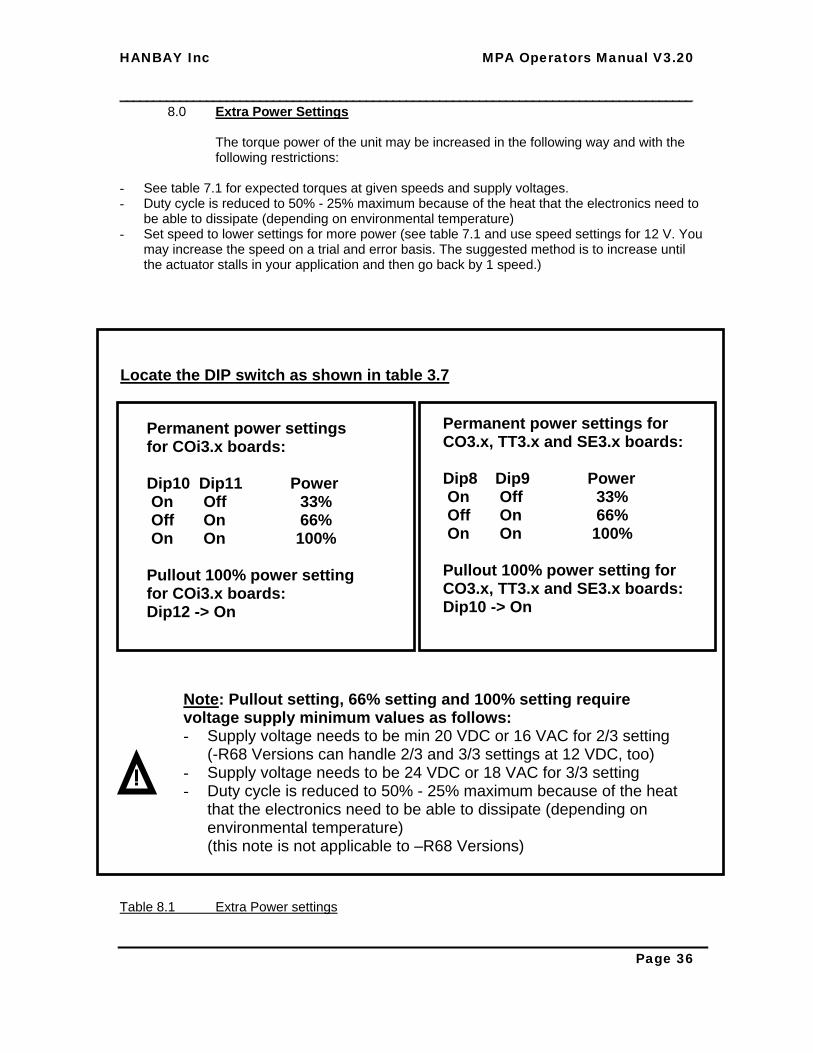
8.0 Extra Power Settings The torque power of the unit may be increased in the following way and with the following restrictions:
- See table 7.1 for expected torques at given speeds and supply voltages. - Duty cycle is reduced to 50% - 25% maximum because of the heat that the electronics need to
be able to dissipate (depending on environmental temperature) - Set speed to lower settings for more power (see table 7.1 and use speed settings for 12 V. You
may increase the speed on a trial and error basis. The suggested method is to increase until the actuator stalls in your application and then go back by 1 speed.)
Table 8.1 Extra Power settings
Locate the DIP switch as shown in table 3.7
Permanent power settings for COi3.x boards: Dip10 Dip11 Power On Off 33% Off On 66% On On 100% Pullout 100% power setting for COi3.x boards: Dip12 -> On
Note: Pullout setting, 66% setting and 100% setting require voltage supply minimum values as follows: - Supply voltage needs to be min 20 VDC or 16 VAC for 2/3 setting
(-R68 Versions can handle 2/3 and 3/3 settings at 12 VDC, too) - Supply voltage needs to be 24 VDC or 18 VAC for 3/3 setting - Duty cycle is reduced to 50% - 25% maximum because of the heat
that the electronics need to be able to dissipate (depending on environmental temperature) (this note is not applicable to –R68 Versions)
Permanent power settings for CO3.x, TT3.x and SE3.x boards: Dip8 Dip9 Power On Off 33% Off On 66% On On 100% Pullout 100% power setting for CO3.x, TT3.x and SE3.x boards: Dip10 -> On

HANBAY Inc MPA Operators Manual V3.20 ______________________________________________________________________________________
Page 37
9.0 Ordering Information Table 9.1 Ordering
0 TTL Digital Communication1 Serial Communication, discrete positions
1 Mechanical Position Indicator Option2 Manual Mechanical Positioning Option
Multi Position Actuator
4 Micro-step, Serial, 4’706 steps / revolution5 Micro-step, Serial, 1’568 steps / revolution
M A P
6 Micro-step, Serial, 17’647 steps / revolution for reducer version only
Analog Com. 4 .. 20mA or 1 .. 5V 23RPM2
Analog Com. isolated 8 RPM3i
0 No Valve or Mounting Plate 1 Mounting Plate Only 3 Valve with Mounting Plate, Mounted Assembly
- -
Valve Manufacturers Valve Part Number
Analog Com. isolated 23RPM2i Analog Com. 4 .. 20mA or 1 .. 5V 8 RPM3

HANBAY Inc MPA Operators Manual V3.20 ______________________________________________________________________________________
Page 38
10.0 Main dimensions with some valves Table 10.1 Main Dimensions
Valve Hamilton HVX
Valve Parker ..-MB6....-..
Valve Parker ..-MB2....-.. ..-MB4....-..
Needle Valve Parker 4M4Z-V4AN-SS

HANBAY Inc MPA Operators Manual V3.20 ______________________________________________________________________________________
Page 39
11.0 Contact Information For inquiries about price, delivery and any technical questions, please contact us at:
Hanbay Inc. 8 Woodland Av. Beaconsfield PQ
H9W 4V9 Canada
Phone: 514 426 1989 800 315 4461
Fax: 514 426 9834
Or e-mail to: [email protected]
For the newest versions of all documents please visit:
www.HanbayInc.com
![Valve terminal MPA-S - Festo USA · Pneumatic components description Valveterminalwith MPA-Spneumatics Type: MPA-FB MPA-CPI MPA-MPM-…and MPA-ASI-… 534241 1309f [8028624] Valve](https://img.pdfslide.net/doc/110x75/5c5bd85409d3f236368c6efe/valve-terminal-mpa-s-festo-usa-pneumatic-components-description-valveterminalwith.jpg)


![Ventilinsel MPA-S - festo.com · PDF fileBeschreibung Pneumatik Ventilinselmit MPA-S Pneumatik Typ: MPA-FB MPA-CPI MPA-MPM-und MPA-ASI- 534240 1309f [8028623] Ventilinsel MPA-S](https://img.pdfslide.net/doc/110x75/5a79d19f7f8b9ab83f8b7435/ventilinsel-mpa-s-festocom-pneumatik-ventilinselmit-mpa-s-pneumatik-typ-mpa-fb.jpg)


![Ventilterminal MPA−L...Pneumatik MPA−L Ventilterminal Typ: MPA−L−MPM−VI MPA−L−FB−VI Beskrivning 556 358 sv 1008NH [722 283] Ventilterminal MPA−L. ... betyder att](https://img.pdfslide.net/doc/110x75/60912199dc0d2a008521a11b/ventilterminal-mpaal-pneumatik-mpaal-ventilterminal-typ-mpaalampmavi.jpg)