Embed Size (px)
Citation preview
Library for Building Automation
Function Block Description for MP-Bus – Master module 750-643
Last update: 30.07.2008
Copyright © 2008 by WAGO Kontakttechnik GmbH & Co. KG All rights reserved.
WAGO Kontakttechnik GmbH & Co. KG Hansastraße 27 D-32423 Minden
Phone: +49 (0) 571/8 87 – 0 Fax: +49 (0) 571/8 87 – 1 69
E-Mail:[email protected]
Web:http://www.wago.com
Technical Support Phone: +49 (0) 571/8 87 – 777 Fax: +49 (0) 571/8 87 – 8777
E-Mail: [email protected]
Every conceivable measure has been taken to ensure the accuracy and completeness of this documentation. However, as errors can never be fully excluded, we always appreciate any information or suggestions for improving the documentation. We wish to point out that the software and hardware terms as well as the trademarks of companies used and/or mentioned in the present manual are generally protected by trademark or patent.
Subject to design changes WAGO Kontakttechnik GmbH & Co. KG PO Box 2880 • D-32385 Minden Phone: 05 71 / 8 87-0 E-Mail: [email protected] Copyright © 2008 Hansastr. 27 • D-32423 Minden Fax.: 05 71 / 8 87-169 Web: http://www.wago.com 2
Contents
WAGO-I/O-PRO CAA Library for MP-Bus – Master module
Contents
Important Notes 4Copyright..........................................................................................4 Personnel Qualification ....................................................................4 Intended Use....................................................................................4 Scope of Validity ..............................................................................5
Communication modules 6MP-Bus Master (FbMpBusMaster)...................................................6 MP-Bus Master IPC (FbMpBusMasterIPC)......................................7 MP-Bus Addressing (FbMpBusAddressing) .....................................9
Actuators 11Damper/Linear actuator (FbMpBusDamperAndLinearActuator) ....11 Volume flow regulator (FbMpBusVav)............................................14 Smoke and fire protection damper (FbMpBusSmokeDamper).......18 Window ventilation system (FbMpBusWindow) .............................21
Sensors 24PTH Combi Sensor (FbMpBusPTH_Sensor) .................................24 Signal transmitter UST-3 (FbMpBus_UST3) ..................................26
Resistance characteristic curves 28NI 1000, Ni1000L&S, PT1000, and NTC5K (e. g. Fu_NI1000) ......28
Appendix 29Error codes ....................................................................................29
Subject to design changes WAGO Kontakttechnik GmbH & Co. KG PO Box 2880 • D-32385 Minden Phone: 05 71 / 8 87-0 E-Mail: [email protected] Copyright © 2008 Hansastr. 27 • D-32423 Minden Fax.: 05 71 / 8 87-169 Web: http://www.wago.com
3
Important Notes
Important Notes To ensure quick installation and start-up of the units, we strongly recommend that you read and follow the information and explanations below.
Copyright
This document, including all figures and illustrations contained therein, is subject to copyright. Any use of this document that infringes upon the copyright provisions stipulated herein is not permitted. Reproduction, translation into other languages and electronic and photographic archiving and amendments require the written consent of WAGO Kontakttechnik GmbH & Co. KG, Minden. Non-observance will entail the right of claims for damages. WAGO Kontakttechnik GmbH & Co. KG reserves the right to enact changes that serve technical progress. All rights developing from the issue of a patent or the legal protection of utility patents are reserved to WAGO Kontakttechnik GmbH & Co. KG. Third-party products are always indicated without any notes concerning patent rights. Thus, the existence of such rights must not be excluded.
Personnel Qualification
The use of the product detailed in this document is geared exclusively to specialists who have qualifications in PLC programming, electrical specialists or persons instructed by electrical specialists who are also familiar with the valid standards. WAGO Kontakttechnik GmbH & Co. KG assumes no liability resulting from improper action and damage to WAGO products and third party products due to non-observance of the information contained in this document.
Intended Use
For each individual application, the components are supplied from the factory with a dedicated hardware and software configuration. Modifications are only permitted within the framework of the possibilities documented in this document. All other changes to the hardware and/or software and the non-conforming use of the components entail the exclusion of liability on part of WAGO Kontakttechnik GmbH & Co. KG. Please direct any requirements pertaining to a modified and/or new hardware or software configuration directly to WAGO Kontakttechnik GmbH & Co. KG.
Subject to design changes WAGO Kontakttechnik GmbH & Co. KG PO Box 2880 • D-32385 Minden Phone: 05 71 / 8 87-0 E-Mail: [email protected] Copyright © 2008 Hansastr. 27 • D-32423 Minden Fax.: 05 71 / 8 87-169 Web: http://www.wago.com 4
Important Notes
Scope of Validity
This application note is based on the stated hardware and software of the specific manufacturer as well as the associated documentation. This application note is therefore only valid for the described installation. New hardware and software versions may need to be handled differently.
Please note the detailed description in the specific manuals.
Subject to design changes WAGO Kontakttechnik GmbH & Co. KG PO Box 2880 • D-32385 Minden Phone: 05 71 / 8 87-0 E-Mail: [email protected] Copyright © 2008 Hansastr. 27 • D-32423 Minden Fax.: 05 71 / 8 87-169 Web: http://www.wago.com
5
MP-Bus Master (FbMpBusMaster)
Communication modules
MP-Bus Master (FbMpBusMaster)
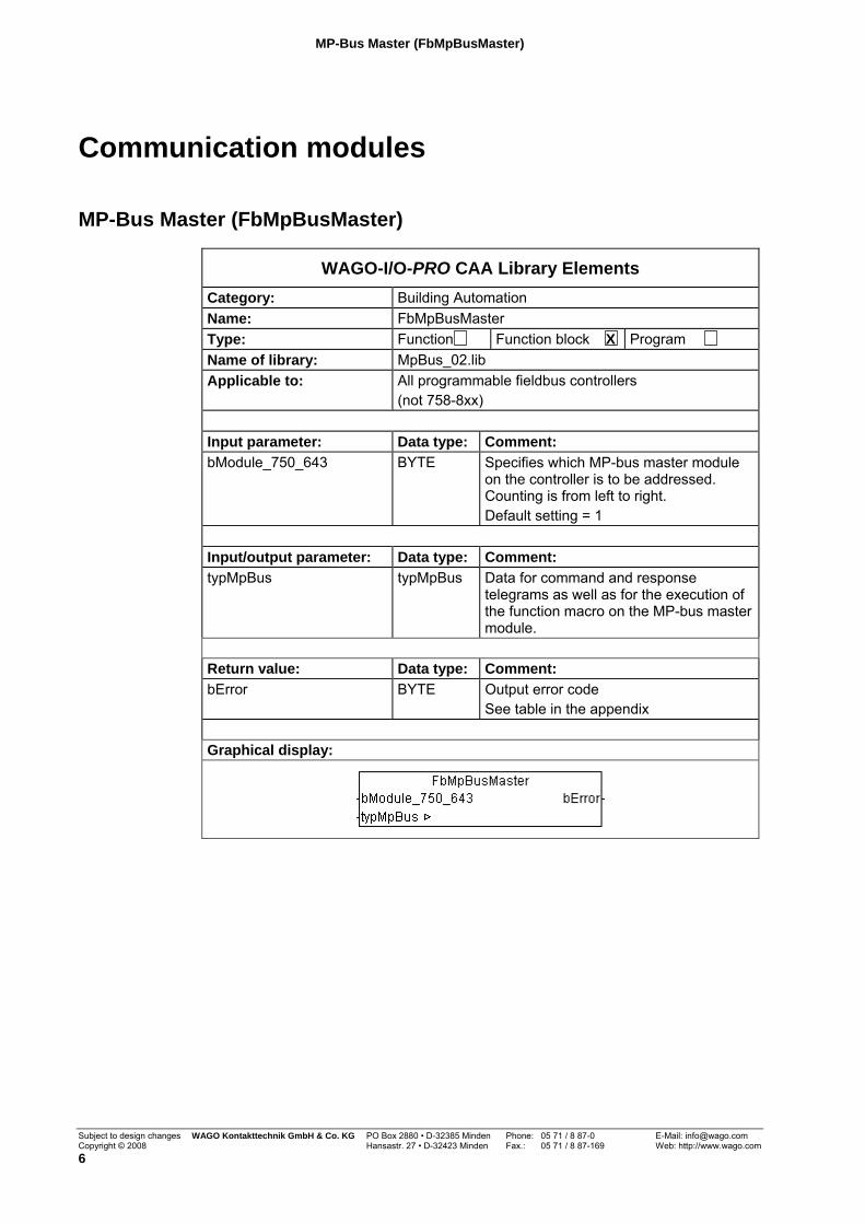
WAGO-I/O-PRO CAA Library Elements Category: Building Automation Name: FbMpBusMaster Type: Function Function block X Program Name of library: MpBus_02.lib Applicable to: All programmable fieldbus controllers
(not 758-8xx) Input parameter: Data type: Comment: bModule_750_643 BYTE Specifies which MP-bus master module
on the controller is to be addressed. Counting is from left to right. Default setting = 1
Input/output parameter: Data type: Comment: typMpBus typMpBus Data for command and response
telegrams as well as for the execution of the function macro on the MP-bus master module.
Return value: Data type: Comment: bError BYTE Output error code
See table in the appendix Graphical display:
Subject to design changes WAGO Kontakttechnik GmbH & Co. KG PO Box 2880 • D-32385 Minden Phone: 05 71 / 8 87-0 E-Mail: [email protected] Copyright © 2008 Hansastr. 27 • D-32423 Minden Fax.: 05 71 / 8 87-169 Web: http://www.wago.com 6
Function description:
The function module FbMpBusMaster can be used for the communication with the MP-bus master 750-643 for all programmable fieldbus controllers.
It collects all incoming commands of the additional MP-bus modules that exist in the program and takes care of their execution. The commands are made available in the form of a data table via the variable “typMpBus.” Send and response telegrams are made available in the table.
The controller detects the connected MP-bus modules independently and counts these beginning from the left. To address the function block to the proper MP-bus module, the corresponding module index must be entered as a constant on the input “bModule_750_643.“
An error can be identified by the error code that is displayed on the output "bError".
Note: This function block may be used only once per installed MP-bus master module. All other MP-bus function blocks must be linked with this function block via the input variable "typMpBus".
MP-Bus Master IPC (FbMpBusMasterIPC)
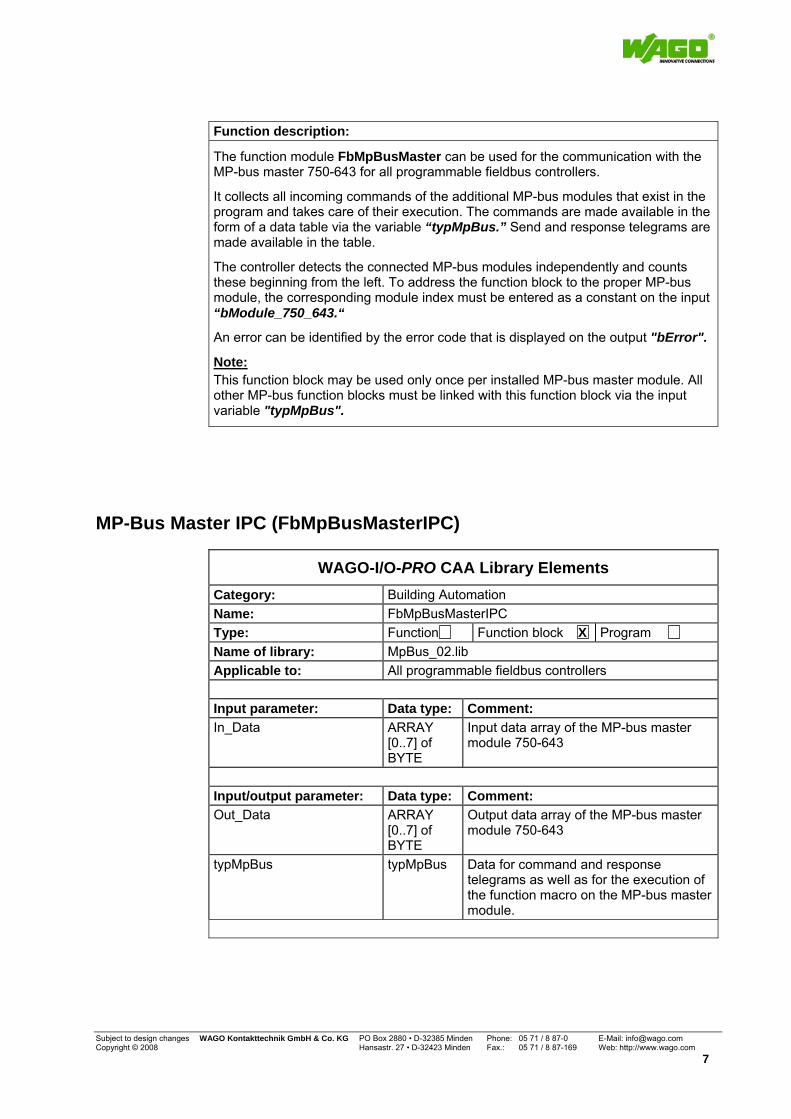
WAGO-I/O-PRO CAA Library Elements Category: Building Automation Name: FbMpBusMasterIPC Type: Function Function block X Program Name of library: MpBus_02.lib Applicable to: All programmable fieldbus controllers Input parameter: Data type: Comment: In_Data ARRAY
[0..7] of BYTE
Input data array of the MP-bus master module 750-643
Input/output parameter: Data type: Comment: Out_Data ARRAY
[0..7] of BYTE
Output data array of the MP-bus master module 750-643
typMpBus typMpBus Data for command and response telegrams as well as for the execution of the function macro on the MP-bus master module.
Subject to design changes WAGO Kontakttechnik GmbH & Co. KG PO Box 2880 • D-32385 Minden Phone: 05 71 / 8 87-0 E-Mail: [email protected] Copyright © 2008 Hansastr. 27 • D-32423 Minden Fax.: 05 71 / 8 87-169 Web: http://www.wago.com
7
MP-Bus Master IPC (FbMpBusMasterIPC)
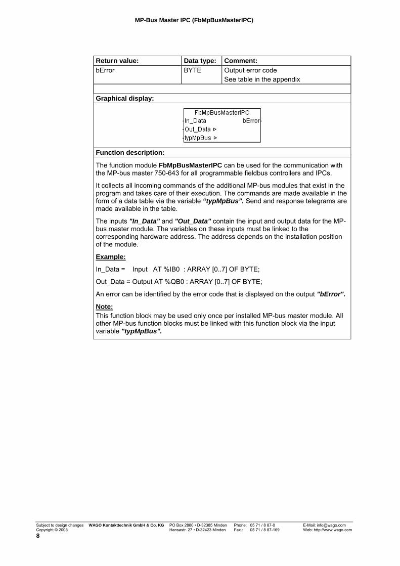
Return value: Data type: Comment: bError BYTE Output error code
See table in the appendix Graphical display:
Function description:
The function module FbMpBusMasterIPC can be used for the communication with the MP-bus master 750-643 for all programmable fieldbus controllers and IPCs.
It collects all incoming commands of the additional MP-bus modules that exist in the program and takes care of their execution. The commands are made available in the form of a data table via the variable “typMpBus”. Send and response telegrams are made available in the table.
The inputs "In_Data" and "Out_Data" contain the input and output data for the MP-bus master module. The variables on these inputs must be linked to the corresponding hardware address. The address depends on the installation position of the module.
Example:
In_Data = Input AT %IB0 : ARRAY [0..7] OF BYTE;
Out_Data = Output AT %QB0 : ARRAY [0..7] OF BYTE;
An error can be identified by the error code that is displayed on the output "bError".
Note: This function block may be used only once per installed MP-bus master module. All other MP-bus function blocks must be linked with this function block via the input variable "typMpBus".
Subject to design changes WAGO Kontakttechnik GmbH & Co. KG PO Box 2880 • D-32385 Minden Phone: 05 71 / 8 87-0 E-Mail: [email protected] Copyright © 2008 Hansastr. 27 • D-32423 Minden Fax.: 05 71 / 8 87-169 Web: http://www.wago.com 8
MP-Bus Addressing (FbMpBusAddressing)
MP-Bus Addressing (FbMpBusAddressing)
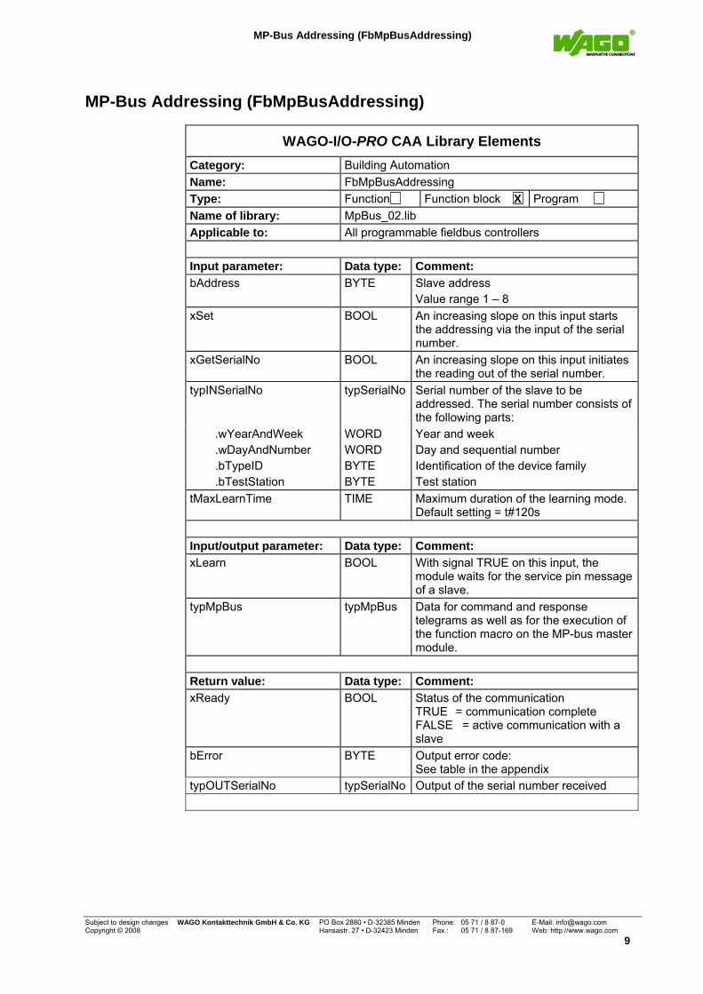
WAGO-I/O-PRO CAA Library Elements Category: Building Automation Name: FbMpBusAddressing Type: Function Function block X Program Name of library: MpBus_02.lib Applicable to: All programmable fieldbus controllers Input parameter: Data type: Comment: bAddress BYTE Slave address
Value range 1 – 8 xSet BOOL An increasing slope on this input starts
the addressing via the input of the serial number.
xGetSerialNo BOOL An increasing slope on this input initiates the reading out of the serial number.
typINSerialNo typSerialNo Serial number of the slave to be addressed. The serial number consists of the following parts:
.wYearAndWeek .wDayAndNumber .bTypeID .bTestStation
WORD WORD BYTE BYTE
Year and week Day and sequential number Identification of the device family Test station
tMaxLearnTime TIME Maximum duration of the learning mode. Default setting = t#120s
Input/output parameter: Data type: Comment: xLearn BOOL With signal TRUE on this input, the
module waits for the service pin message of a slave.
typMpBus typMpBus Data for command and response telegrams as well as for the execution of the function macro on the MP-bus master module.
Return value: Data type: Comment: xReady BOOL Status of the communication
TRUE = communication complete FALSE = active communication with a slave
bError BYTE Output error code: See table in the appendix
typOUTSerialNo typSerialNo Output of the serial number received
Subject to design changes WAGO Kontakttechnik GmbH & Co. KG PO Box 2880 • D-32385 Minden Phone: 05 71 / 8 87-0 E-Mail: [email protected] Copyright © 2008 Hansastr. 27 • D-32423 Minden Fax.: 05 71 / 8 87-169 Web: http://www.wago.com
9
MP-Bus Addressing (FbMpBusAddressing)
Graphical display:
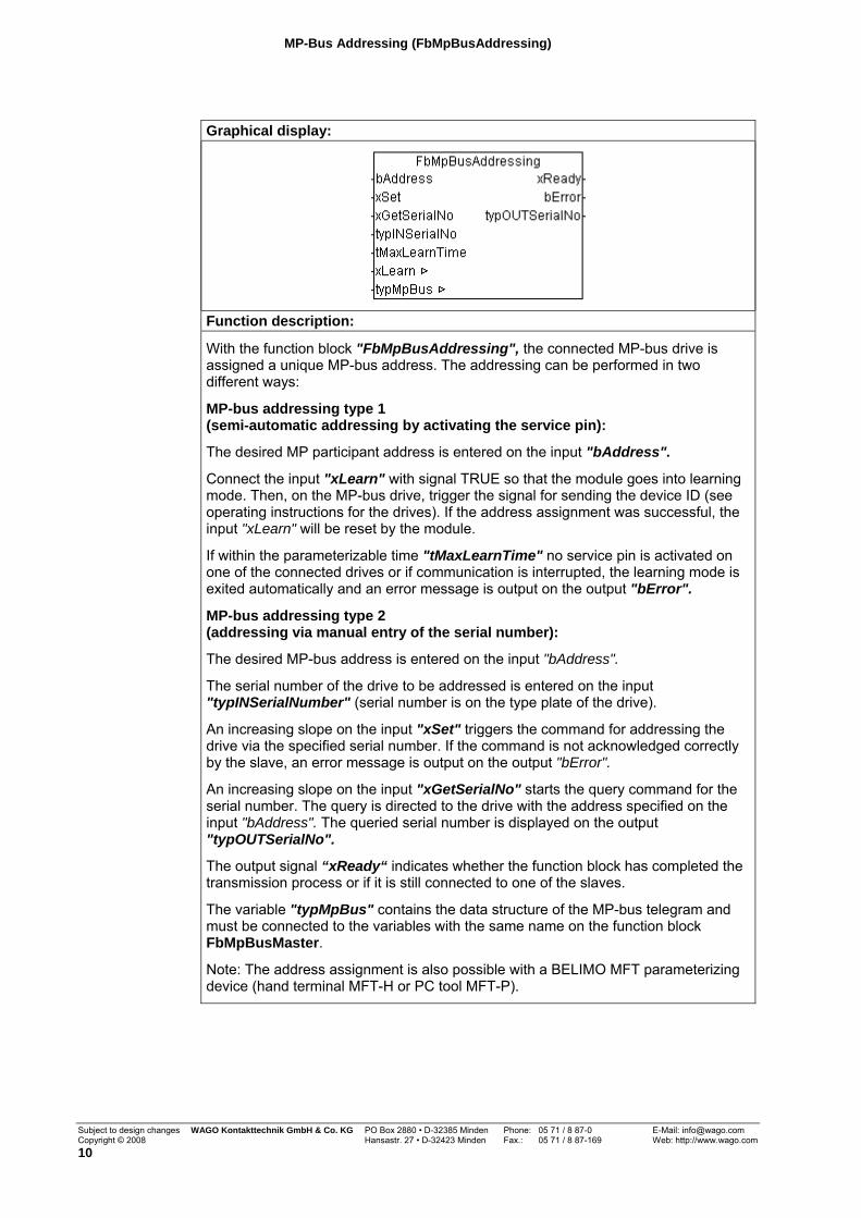
Function description:
With the function block "FbMpBusAddressing", the connected MP-bus drive is assigned a unique MP-bus address. The addressing can be performed in two different ways:
MP-bus addressing type 1 (semi-automatic addressing by activating the service pin):
The desired MP participant address is entered on the input "bAddress".
Connect the input "xLearn" with signal TRUE so that the module goes into learning mode. Then, on the MP-bus drive, trigger the signal for sending the device ID (see operating instructions for the drives). If the address assignment was successful, the input "xLearn" will be reset by the module.
If within the parameterizable time "tMaxLearnTime" no service pin is activated on one of the connected drives or if communication is interrupted, the learning mode is exited automatically and an error message is output on the output "bError".
MP-bus addressing type 2 (addressing via manual entry of the serial number):
The desired MP-bus address is entered on the input "bAddress".
The serial number of the drive to be addressed is entered on the input "typINSerialNumber" (serial number is on the type plate of the drive).
An increasing slope on the input "xSet" triggers the command for addressing the drive via the specified serial number. If the command is not acknowledged correctly by the slave, an error message is output on the output "bError".
An increasing slope on the input "xGetSerialNo" starts the query command for the serial number. The query is directed to the drive with the address specified on the input "bAddress". The queried serial number is displayed on the output "typOUTSerialNo".
The output signal “xReady“ indicates whether the function block has completed the transmission process or if it is still connected to one of the slaves.
The variable "typMpBus" contains the data structure of the MP-bus telegram and must be connected to the variables with the same name on the function block FbMpBusMaster.
Note: The address assignment is also possible with a BELIMO MFT parameterizing device (hand terminal MFT-H or PC tool MFT-P).
Subject to design changes WAGO Kontakttechnik GmbH & Co. KG PO Box 2880 • D-32385 Minden Phone: 05 71 / 8 87-0 E-Mail: [email protected] Copyright © 2008 Hansastr. 27 • D-32423 Minden Fax.: 05 71 / 8 87-169 Web: http://www.wago.com 10
Damper/Linear actuator (FbMpBusDamperAndLinearActuator)
Actuators
Damper/Linear actuator (FbMpBusDamperAndLinearActuator)
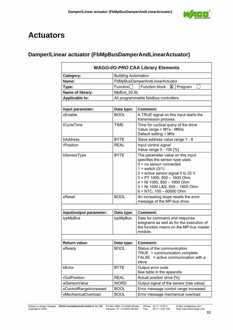
WAGO-I/O-PRO CAA Library Elements Category: Building Automation Name: FbMpBusDamperAndLinearActuator Type: Function Function block X Program Name of library: MpBus_02.lib Applicable to: All programmable fieldbus controllers Input parameter: Data type: Comment: xEnable BOOL A TRUE signal on this input starts the
transmission process. tCycleTime TIME Time for cyclical query of the drive
Value range = t#1s - t#60s Default setting = t#5s
bAddress BYTE Slave address value range 1 - 8 rPosition REAL Input control signal
Value range 0 - 100 [%] bSensorType BYTE The parameter value on this input
specifies the sensor type used: 0 = no sensor connected 1 = switch (0/1) 2 = active sensor signal 0 to 32 V 3 = PT 1000, 850 – 1600 Ohm 4 = NI 1000, 850 – 1600 Ohm 5 = NI 1000 L&S, 850 – 1600 Ohm 6 = NTC, 100 – 60000 Ohm
xReset BOOL An increasing slope resets the error message of the MP-bus drive.
Input/output parameter: Data type: Comment: typMpBus typMpBus Data for command and response
telegrams as well as for the execution of the function macro on the MP-bus master module.
Return value: Data type: Comment: xReady BOOL Status of the communication
TRUE = communication complete FALSE = active communication with a slave
bError BYTE Output error code See table in the appendix
rOutPosition REAL Actual position drive [%] wSensorValue WORD Output signal of the sensor [raw value] xControlRangeIncreased BOOL Error message control range increased xMechanicalOverload BOOL Error message mechanical overload
Subject to design changes WAGO Kontakttechnik GmbH & Co. KG PO Box 2880 • D-32385 Minden Phone: 05 71 / 8 87-0 E-Mail: [email protected] Copyright © 2008 Hansastr. 27 • D-32423 Minden Fax.: 05 71 / 8 87-169 Web: http://www.wago.com
11
Damper/Linear actuator (FbMpBusDamperAndLinearActuator)
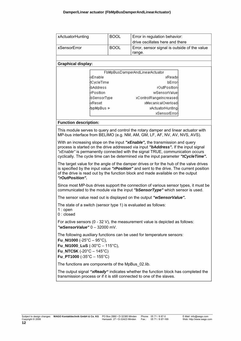
xActuatorHunting BOOL Error in regulation behavior:
drive oscillates here and there xSensorError BOOL Error, sensor signal is outside of the value
range. Graphical display:
Function description:
This module serves to query and control the rotary damper and linear actuator with MP-bus interface from BELIMO (e.g. NM, AM, GM, LF, AF, NV, AV, NVS, AVS).
With an increasing slope on the input "xEnable", the transmission and query process is started on the drive addressed via input "bAddress". If the input signal "xEnable" is permanently connected with the signal TRUE, communication occurs cyclically. The cycle time can be determined via the input parameter "tCycleTime".
The target value for the angle of the damper drives or for the hub of the valve drives is specified by the input value "rPosition" and sent to the drive. The current position of the drive is read out by the function block and made available on the output "rOutPosition".
Since most MP-bus drives support the connection of various sensor types, it must be communicated to the module via the input "bSensorType" which sensor is used.
The sensor value read out is displayed on the output "wSensorValue".
The state of a switch (sensor type 1) is evaluated as follows: 1 : open 0 : closed
For active sensors (0 - 32 V), the measurement value is depicted as follows: "wSensorValue" 0 – 32000 mV.
The following auxiliary functions can be used for temperature sensors: Fu_NI1000 (-25°C – 95°C), Fu_NI1000_LuS (-30°C – 115°C), Fu_NTC5K (-20°C – 145°C) Fu_PT1000 (-35°C – 155°C)
The functions are components of the MpBus_02.lib.
The output signal “xReady“ indicates whether the function block has completed the transmission process or if it is still connected to one of the slaves.
Subject to design changes WAGO Kontakttechnik GmbH & Co. KG PO Box 2880 • D-32385 Minden Phone: 05 71 / 8 87-0 E-Mail: [email protected] Copyright © 2008 Hansastr. 27 • D-32423 Minden Fax.: 05 71 / 8 87-169 Web: http://www.wago.com 12
Damper/Linear actuator (FbMpBusDamperAndLinearActuator)
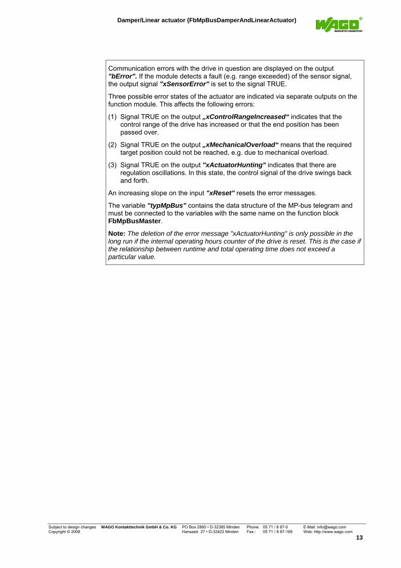
Communication errors with the drive in question are displayed on the output "bError". If the module detects a fault (e.g. range exceeded) of the sensor signal, the output signal "xSensorError" is set to the signal TRUE.
Three possible error states of the actuator are indicated via separate outputs on the function module. This affects the following errors:
(1) Signal TRUE on the output „xControlRangeIncreased“ indicates that the control range of the drive has increased or that the end position has been passed over.
(2) Signal TRUE on the output „xMechanicalOverload“ means that the required target position could not be reached, e.g. due to mechanical overload.
(3) Signal TRUE on the output "xActuatorHunting" indicates that there are regulation oscillations. In this state, the control signal of the drive swings back and forth.
An increasing slope on the input "xReset" resets the error messages.
The variable "typMpBus" contains the data structure of the MP-bus telegram and must be connected to the variables with the same name on the function block FbMpBusMaster.
Note: The deletion of the error message "xActuatorHunting" is only possible in the long run if the internal operating hours counter of the drive is reset. This is the case if the relationship between runtime and total operating time does not exceed a particular value.
Subject to design changes WAGO Kontakttechnik GmbH & Co. KG PO Box 2880 • D-32385 Minden Phone: 05 71 / 8 87-0 E-Mail: [email protected] Copyright © 2008 Hansastr. 27 • D-32423 Minden Fax.: 05 71 / 8 87-169 Web: http://www.wago.com
13
Volume flow regulator (FbMpBusVav)
Volume flow regulator (FbMpBusVav)
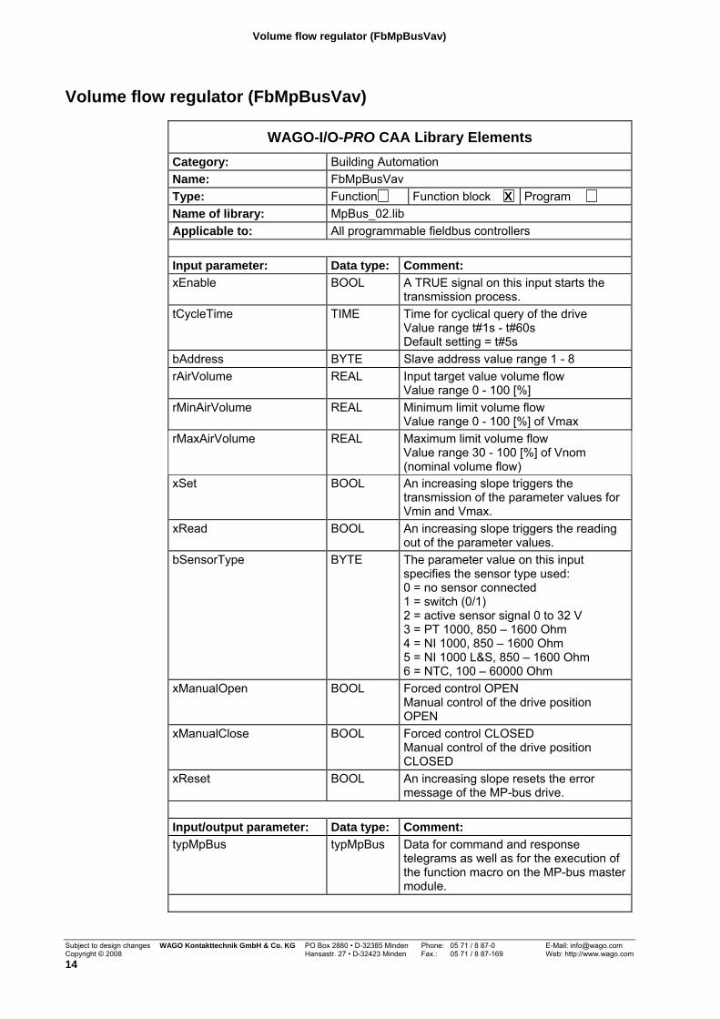
WAGO-I/O-PRO CAA Library Elements Category: Building Automation Name: FbMpBusVav Type: Function Function block X Program Name of library: MpBus_02.lib Applicable to: All programmable fieldbus controllers Input parameter: Data type: Comment: xEnable BOOL A TRUE signal on this input starts the
transmission process. tCycleTime TIME Time for cyclical query of the drive
Value range t#1s - t#60s Default setting = t#5s
bAddress BYTE Slave address value range 1 - 8 rAirVolume REAL Input target value volume flow
Value range 0 - 100 [%] rMinAirVolume REAL Minimum limit volume flow
Value range 0 - 100 [%] of Vmax rMaxAirVolume REAL Maximum limit volume flow
Value range 30 - 100 [%] of Vnom (nominal volume flow)
xSet BOOL An increasing slope triggers the transmission of the parameter values for Vmin and Vmax.
xRead BOOL An increasing slope triggers the reading out of the parameter values.
bSensorType BYTE The parameter value on this input specifies the sensor type used: 0 = no sensor connected 1 = switch (0/1) 2 = active sensor signal 0 to 32 V 3 = PT 1000, 850 – 1600 Ohm 4 = NI 1000, 850 – 1600 Ohm 5 = NI 1000 L&S, 850 – 1600 Ohm 6 = NTC, 100 – 60000 Ohm
xManualOpen BOOL Forced control OPEN Manual control of the drive position OPEN
xManualClose BOOL Forced control CLOSED Manual control of the drive position CLOSED
xReset BOOL An increasing slope resets the error message of the MP-bus drive.
Input/output parameter: Data type: Comment: typMpBus typMpBus Data for command and response
telegrams as well as for the execution of the function macro on the MP-bus master module.
Subject to design changes WAGO Kontakttechnik GmbH & Co. KG PO Box 2880 • D-32385 Minden Phone: 05 71 / 8 87-0 E-Mail: [email protected] Copyright © 2008 Hansastr. 27 • D-32423 Minden Fax.: 05 71 / 8 87-169 Web: http://www.wago.com 14
Volume flow regulator (FbMpBusVav)
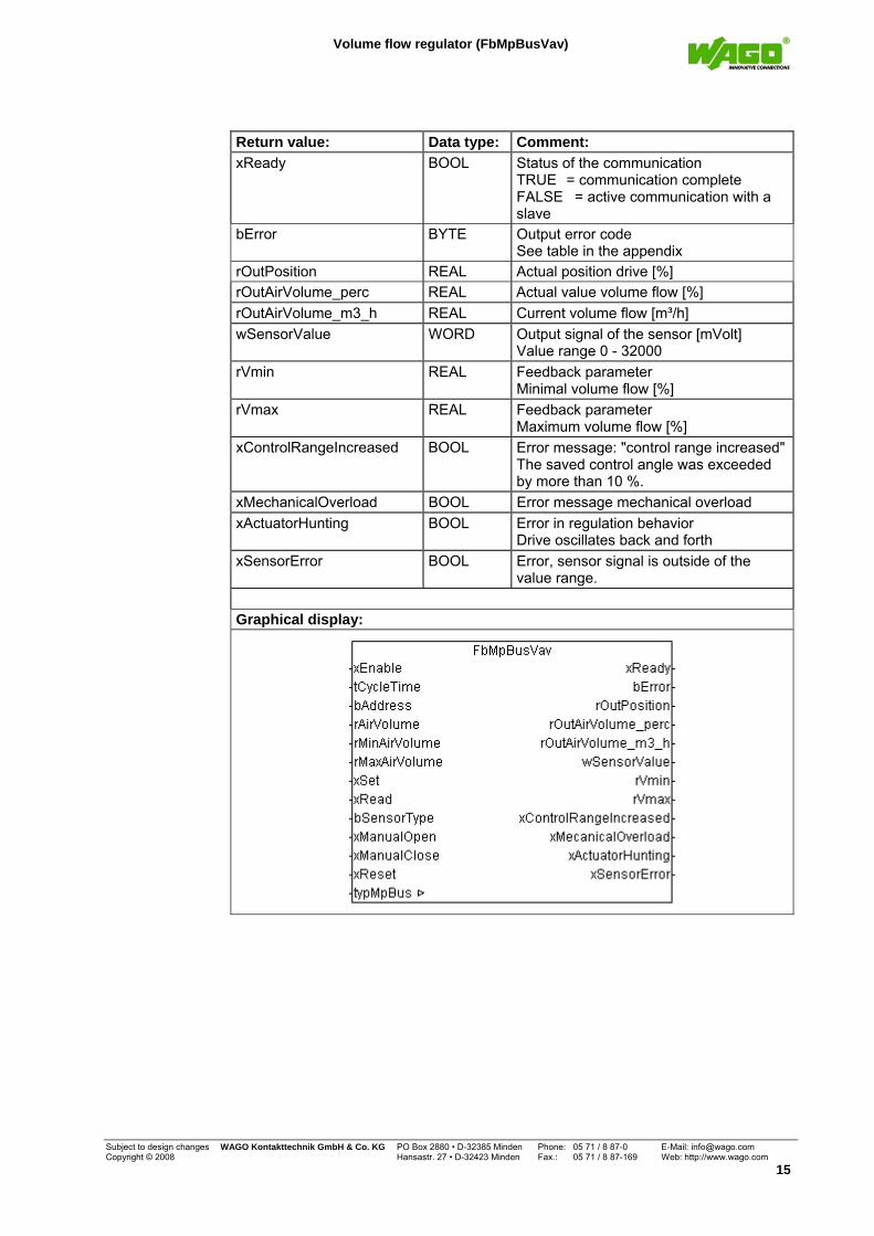
Return value: Data type: Comment: xReady BOOL Status of the communication
TRUE = communication complete FALSE = active communication with a slave
bError BYTE Output error code See table in the appendix
rOutPosition REAL Actual position drive [%] rOutAirVolume_perc REAL Actual value volume flow [%] rOutAirVolume_m3_h REAL Current volume flow [m³/h] wSensorValue WORD Output signal of the sensor [mVolt]
Value range 0 - 32000 rVmin REAL Feedback parameter
Minimal volume flow [%] rVmax
REAL Feedback parameter
Maximum volume flow [%] xControlRangeIncreased BOOL Error message: "control range increased"
The saved control angle was exceeded by more than 10 %.
xMechanicalOverload BOOL Error message mechanical overload xActuatorHunting BOOL Error in regulation behavior
Drive oscillates back and forth xSensorError BOOL Error, sensor signal is outside of the
value range. Graphical display:
Subject to design changes WAGO Kontakttechnik GmbH & Co. KG PO Box 2880 • D-32385 Minden Phone: 05 71 / 8 87-0 E-Mail: [email protected] Copyright © 2008 Hansastr. 27 • D-32423 Minden Fax.: 05 71 / 8 87-169 Web: http://www.wago.com
15
Volume flow regulator (FbMpBusVav)
Function description:
This module handles the query and control of the BELIMO VAV regulator (e.g. NMV-D2M).
With an increasing slope on the input "xEnable", the transmission and query process is started on the drive addressed via input "bAddress". If the input signal "xEnable" is permanently connected with the signal TRUE, communication occurs cyclically. The input parameter “tCycleTime“ determines the cycle time.
The target value for the volume quantity is specified via the value of the input "rAirVolume". A limitation of the volume flow quantity is possible via the two input parameters "rMinAirVolume" (Vmin) and "rMaxAirVolume" (Vmax).
The minimum limitation "Vmin" is specified depending on the value of the maximum limitation "Vmax." The value for the maximum limitation is specified depending on the nominal volume flow (Vnom). The nominal volume flow is specified by the box manufacturer.
A signal as increasing slope on the input "xSet" causes the values "rMinAirVolume" and "rMaxAirVolume" to be transmitted to the drive. The reading out of these values from the drive is caused by an increasing slope on the input "xRead". They are available as output variables "rVmin" and "rVmax" on the module.
The current position of the drive "rOutPosition" and the actual value of the volume flow in percent "rOutAirVolume_perc" (with respect to the nominal volume of the volume flow regulator) are read out of the function block and displayed. Another important variable that is read out of the drive regulator is the current volume flow in m³/h "rOutAirVolume_m3_h." This value depends on the nominal volume flow, which is stored in the device as a parameter.
Since most BELIMO drives support the connection of various sensor types, it must be communicated to the module via the input "bSensorType" which sensor is used.
The sensor value read out is displayed on the output "wSensorValue".
The state of a switch (sensor type 1) is evaluated as follows: 1 : open 0 : closed
For active sensors (0 - 32 V), the measurement value is depicted as follows: "wSensorValue" 0 – 32000 mV.
The following auxiliary functions can be used for temperature sensors: Fu_NI1000 (-25°C – 95°C), Fu_NI1000_LuS (-30°C – 115°C), Fu_NTC5K (-20°C – 145°C) Fu_PT1000 (-35°C – 155°C)
The functions are components of the MpBus_02.lib.
Subject to design changes WAGO Kontakttechnik GmbH & Co. KG PO Box 2880 • D-32385 Minden Phone: 05 71 / 8 87-0 E-Mail: [email protected] Copyright © 2008 Hansastr. 27 • D-32423 Minden Fax.: 05 71 / 8 87-169 Web: http://www.wago.com 16
Volume flow regulator (FbMpBusVav)
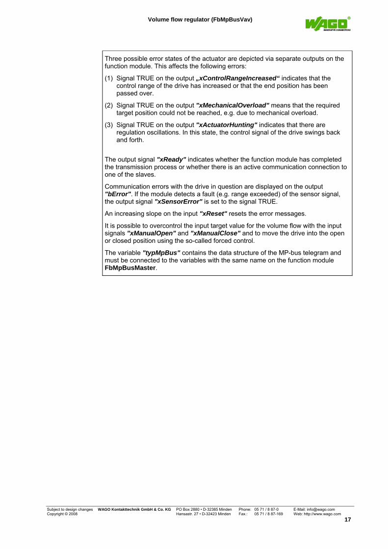
Three possible error states of the actuator are depicted via separate outputs on the function module. This affects the following errors:
(1) Signal TRUE on the output „xControlRangeIncreased“ indicates that the control range of the drive has increased or that the end position has been passed over.
(2) Signal TRUE on the output "xMechanicalOverload" means that the required target position could not be reached, e.g. due to mechanical overload.
(3) Signal TRUE on the output "xActuatorHunting" indicates that there are regulation oscillations. In this state, the control signal of the drive swings back and forth.
The output signal "xReady" indicates whether the function module has completed the transmission process or whether there is an active communication connection to one of the slaves.
Communication errors with the drive in question are displayed on the output "bError". If the module detects a fault (e.g. range exceeded) of the sensor signal, the output signal "xSensorError" is set to the signal TRUE.
An increasing slope on the input "xReset" resets the error messages.
It is possible to overcontrol the input target value for the volume flow with the input signals "xManualOpen" and "xManualClose" and to move the drive into the open or closed position using the so-called forced control.
The variable "typMpBus" contains the data structure of the MP-bus telegram and must be connected to the variables with the same name on the function module FbMpBusMaster.
Subject to design changes WAGO Kontakttechnik GmbH & Co. KG PO Box 2880 • D-32385 Minden Phone: 05 71 / 8 87-0 E-Mail: [email protected] Copyright © 2008 Hansastr. 27 • D-32423 Minden Fax.: 05 71 / 8 87-169 Web: http://www.wago.com
17
Smoke and fire protection damper (FbMpBusSmokeDamper)
Smoke and fire protection damper (FbMpBusSmokeDamper)
Note: in Switzerland, there are no safety regulations for fire protection dampers. If the MP-bus master module is used in this application outside of Switzerland, it cannot be used so that it is relevant to safety.
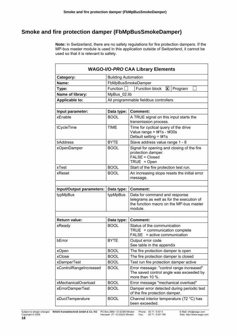
WAGO-I/O-PRO CAA Library Elements Category: Building Automation Name: FbMpBusSmokeDamper Type: Function Function block X Program Name of library: MpBus_02.lib Applicable to: All programmable fieldbus controllers Input parameter: Data type: Comment: xEnable BOOL A TRUE signal on this input starts the
transmission process. tCycleTime TIME Time for cyclical query of the drive
Value range = t#1s - t#30s Default setting = t#1s
bAddress BYTE Slave address value range 1 - 8 xOpenDamper BOOL Signal for opening and closing of the fire
protection damper. FALSE = Closed TRUE = Open
xTest BOOL Start of the fire protection test run. xReset BOOL An increasing slope resets the initial error
message. Input/Output parameters: Data type: Comment: typMpBus typMpBus Data for command and response
telegrams as well as for the execution of the function macro on the MP-bus master module.
Return value: Data type: Comment: xReady BOOL Status of the communication
TRUE = communication complete FALSE = active communication
bError BYTE Output error code See table in the appendix
xOpen BOOL The fire protection damper is open xClose BOOL The fire protection damper is closed xDamperTest BOOL Test run fire protection damper active xControlRangeIncreased BOOL Error message: "control range increased"
The saved control angle was exceeded by more than 10 %.
xMechanicalOverload BOOL Error message "mechanical overload" xErrorDamperTest BOOL Damper error detected during periodic test
of the fire protection damper. xDuctTemperature BOOL Channel interior temperature (72 °C) has
been exceeded.
Subject to design changes WAGO Kontakttechnik GmbH & Co. KG PO Box 2880 • D-32385 Minden Phone: 05 71 / 8 87-0 E-Mail: [email protected] Copyright © 2008 Hansastr. 27 • D-32423 Minden Fax.: 05 71 / 8 87-169 Web: http://www.wago.com 18
Smoke and fire protection damper (FbMpBusSmokeDamper)
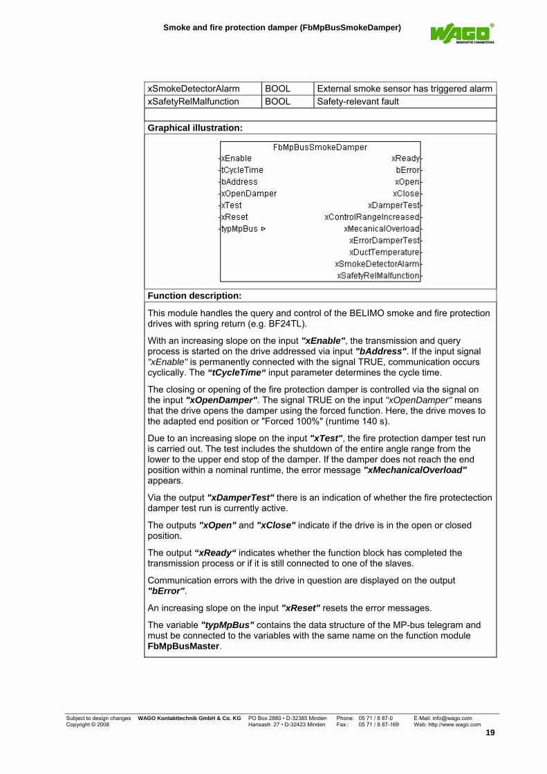
xSmokeDetectorAlarm BOOL External smoke sensor has triggered alarmxSafetyRelMalfunction BOOL Safety-relevant fault Graphical illustration:
Function description:
This module handles the query and control of the BELIMO smoke and fire protection drives with spring return (e.g. BF24TL).
With an increasing slope on the input "xEnable", the transmission and query process is started on the drive addressed via input "bAddress". If the input signal "xEnable" is permanently connected with the signal TRUE, communication occurs cyclically. The “tCycleTime“ input parameter determines the cycle time.
The closing or opening of the fire protection damper is controlled via the signal on the input "xOpenDamper". The signal TRUE on the input "xOpenDamper" means that the drive opens the damper using the forced function. Here, the drive moves to the adapted end position or "Forced 100%" (runtime 140 s).
Due to an increasing slope on the input "xTest", the fire protection damper test run is carried out. The test includes the shutdown of the entire angle range from the lower to the upper end stop of the damper. If the damper does not reach the end position within a nominal runtime, the error message "xMechanicalOverload" appears.
Via the output "xDamperTest" there is an indication of whether the fire protectection damper test run is currently active.
The outputs "xOpen" and "xClose" indicate if the drive is in the open or closed position.
The output “xReady“ indicates whether the function block has completed the transmission process or if it is still connected to one of the slaves.
Communication errors with the drive in question are displayed on the output "bError".
An increasing slope on the input "xReset" resets the error messages.
The variable "typMpBus" contains the data structure of the MP-bus telegram and must be connected to the variables with the same name on the function module FbMpBusMaster.
Subject to design changes WAGO Kontakttechnik GmbH & Co. KG PO Box 2880 • D-32385 Minden Phone: 05 71 / 8 87-0 E-Mail: [email protected] Copyright © 2008 Hansastr. 27 • D-32423 Minden Fax.: 05 71 / 8 87-169 Web: http://www.wago.com
19
Smoke and fire protection damper (FbMpBusSmokeDamper)
The drive for the fire protection damper monitors the following error states, which are indicated by the controller:
(1) „xControlRangeIncreased“ means: the drive angle of rotation has been exceeded by more than 10 ° (e.g. in case of frame break). As soon as the stop is in the correct location again, the error message is deleted.
(2) „xMechanicalOverload“ means: the angle of rotation is smaller with respect to the adaptation (e.g. obstacle in the damper or stuck damper). This error also occurs if the mechanical end switch of the drive does not close in the closed position.
(3) „xErrorDamperTest“ means: "damper mobility error." If the damper is in the open position, then every 24 hours the drive moves the damper slowly, that is with spring force and motor brake, 7 s back and then open again using motor force. If the drive achieves less than a 5 °angle change during this time, there is an error message. Note: the damper mobility test is started every 24 hours. The error message is deleted automatically with the next successful test run.
(4) „xDuctTemperature“ means: fault channel interior temperature too high. The channel interior temperature > 72 °C has been exceeded. The thermoelectric trigger mechanism in the channel has been triggered. Only after changing out the channel temperature fuse can this fault be acknowledged.
(5) “xSmokeDetectorAlarm“ means: alarm smoke detector. The fire detector contact of the (optionally) connected smoke detector has opened.
(6) „xSafetyRelMalfunction“ means: safety-relevant fault. An ambient temperature > 72 °C or a motor temperature > 85 °C cause this fault message to be triggered. Here the drive is moved into the "emergency" position. The message can only be reset in the factory by BELIMO.
Note: For safety reasons, a timeout monitoring is implemented in the drives for the fire protection dampers. If the function module sends a forced command to the drive, the bus monitoring in the drive is activated. If now the drive does not receive a command from the function module within 60 seconds, the drive closes. With renewed communication, the target value of the controller applies once again.
Subject to design changes WAGO Kontakttechnik GmbH & Co. KG PO Box 2880 • D-32385 Minden Phone: 05 71 / 8 87-0 E-Mail: [email protected] Copyright © 2008 Hansastr. 27 • D-32423 Minden Fax.: 05 71 / 8 87-169 Web: http://www.wago.com 20
Window ventilation system (FbMpBusWindow)
Window ventilation system (FbMpBusWindow)
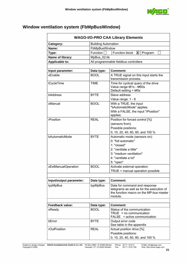
WAGO-I/O-PRO CAA Library Elements Category: Building Automation Name: FbMpBusWindow Type: Function Function block X Program Name of library: MpBus_02.lib Applicable to: All programmable fieldbus controllers Input parameter: Data type: Comment: xEnable BOOL A TRUE signal on this input starts the
transmission process. tCycleTime TIME Time for cyclical query of the drive
Value range t#1s - t#60s Default setting = t#5s
bAddress BYTE Slave address Value range: 1 - 8
xManual BOOL With a TRUE, the input "bAutomaticMode" applies. With a FALSE, the input "rPosition" applies.
rPosition REAL Position for forced control [%] (sensors from) Possible positions: 0, 10, 20, 40, 60, 80, and 100 %
bAutomaticMode BYTE Automatic mode (sensors on): 0: "full automatic" 1: "closed" 2: "ventilate a little" 3: "medium ventilation" 4: "ventilate a lot" 5: "open"
xExtManualOperation BOOL Activate external operation TRUE = manual operation possible
Input/output parameter: Data type: Comment: typMpBus typMpBus Data for command and response
telegrams as well as for the execution of the function macro on the MP-bus master module.
Feedback value: Data type: Comment: xReady BOOL Status of the communication
TRUE = no communication FALSE = active communication
bError BYTE Output error code See table in the appendix
rOutPosition REAL Actual position drive [%] Possible positions: 0, 10, 20, 40, 60, 80, and 100 %
Subject to design changes WAGO Kontakttechnik GmbH & Co. KG PO Box 2880 • D-32385 Minden Phone: 05 71 / 8 87-0 E-Mail: [email protected] Copyright © 2008 Hansastr. 27 • D-32423 Minden Fax.: 05 71 / 8 87-169 Web: http://www.wago.com
21
Window ventilation system (FbMpBusWindow)
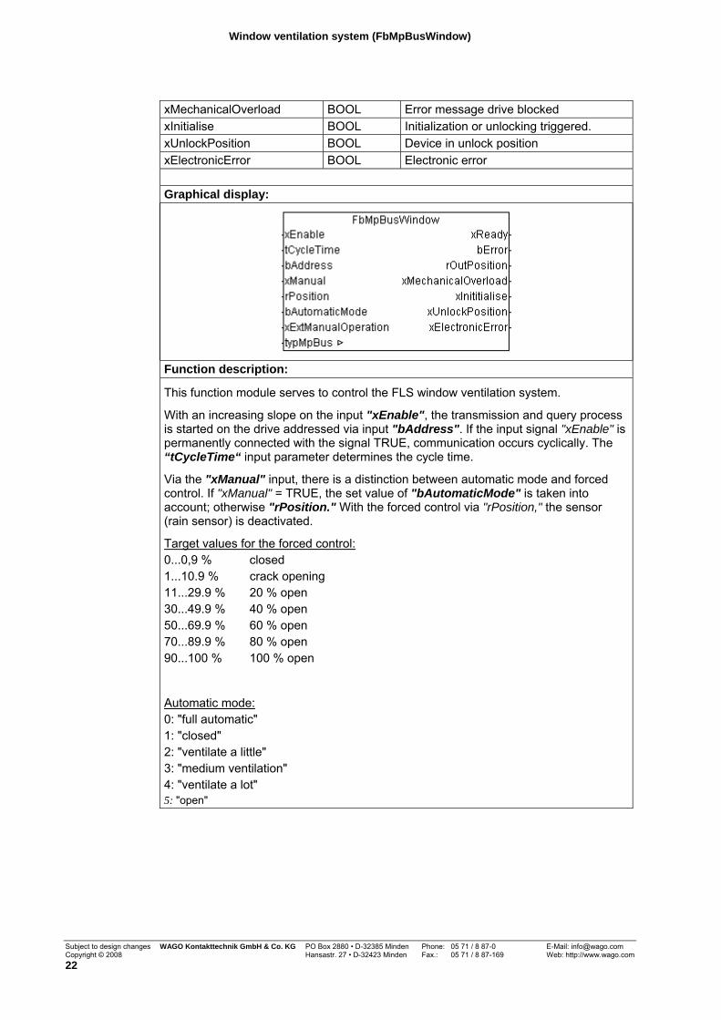
xMechanicalOverload BOOL Error message drive blocked xInitialise BOOL Initialization or unlocking triggered. xUnlockPosition BOOL Device in unlock position xElectronicError BOOL Electronic error Graphical display:
Function description:
This function module serves to control the FLS window ventilation system.
With an increasing slope on the input "xEnable", the transmission and query process is started on the drive addressed via input "bAddress". If the input signal "xEnable" is permanently connected with the signal TRUE, communication occurs cyclically. The “tCycleTime“ input parameter determines the cycle time.
Via the "xManual" input, there is a distinction between automatic mode and forced control. If "xManual" = TRUE, the set value of "bAutomaticMode" is taken into account; otherwise "rPosition." With the forced control via "rPosition," the sensor (rain sensor) is deactivated.
Target values for the forced control: 0...0,9 % closed 1...10.9 % crack opening 11...29.9 % 20 % open 30...49.9 % 40 % open 50...69.9 % 60 % open 70...89.9 % 80 % open 90...100 % 100 % open
Automatic mode: 0: "full automatic" 1: "closed" 2: "ventilate a little" 3: "medium ventilation" 4: "ventilate a lot" 5: "open"
Subject to design changes WAGO Kontakttechnik GmbH & Co. KG PO Box 2880 • D-32385 Minden Phone: 05 71 / 8 87-0 E-Mail: [email protected] Copyright © 2008 Hansastr. 27 • D-32423 Minden Fax.: 05 71 / 8 87-169 Web: http://www.wago.com 22
Window ventilation system (FbMpBusWindow)
Via the "xExtManualOperation" input, the operation of manual switches or remote controls is enabled.
The variable "typMpBus" contains the data structure of the MP-bus telegram and must be connected to the variables with the same name on the function module FbMpBusMaster.
The output “xReady“ indicates whether the function block has completed the transmission process or if it is still connected to one of the slaves.
Communication errors with the drive in question are displayed on the output "bError".
The current position of the drive is read out by the function block and made available on the output "rOutPosition".
Four possible error states of the FLS are depicted via separate outputs on the function module. This affects the following errors:
(1) Signal TRUE on the output "xMechanicalOverload" means that the required target position could not be reached, e.g. due to blockage of the window.
(2) Signal TRUE on the output "xInitialise" indicates that the initialization or unlocking was triggered.
(3) Signal TRUE on the output "xUnlockPosition" indicates that the FLS is in the unlock position.
(4) Signal TRUE on the output "xElectronicError" means that there is an electronic error and the drive must be reprogrammed or replaced.
Subject to design changes WAGO Kontakttechnik GmbH & Co. KG PO Box 2880 • D-32385 Minden Phone: 05 71 / 8 87-0 E-Mail: [email protected] Copyright © 2008 Hansastr. 27 • D-32423 Minden Fax.: 05 71 / 8 87-169 Web: http://www.wago.com
23
PTH Combi Sensor (FbMpBusPTH_Sensor)
Sensors
PTH Combi Sensor (FbMpBusPTH_Sensor)
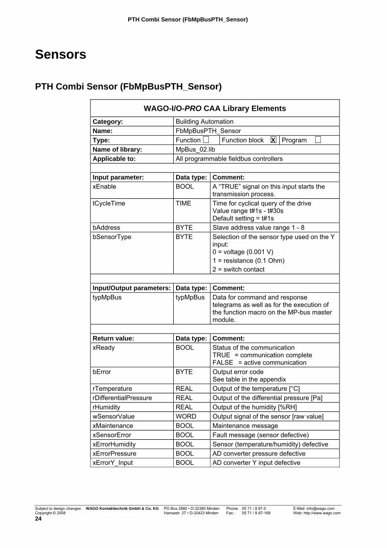
WAGO-I/O-PRO CAA Library Elements Category: Building Automation Name: FbMpBusPTH_Sensor Type: Function Function block X Program Name of library: MpBus_02.lib Applicable to: All programmable fieldbus controllers Input parameter: Data type: Comment: xEnable BOOL A “TRUE” signal on this input starts the
transmission process. tCycleTime TIME Time for cyclical query of the drive
Value range t#1s - t#30s Default setting = t#1s
bAddress BYTE Slave address value range 1 - 8 bSensorType BYTE Selection of the sensor type used on the Y
input: 0 = voltage (0.001 V) 1 = resistance (0.1 Ohm) 2 = switch contact
Input/Output parameters: Data type: Comment: typMpBus typMpBus Data for command and response
telegrams as well as for the execution of the function macro on the MP-bus master module.
Return value: Data type: Comment: xReady BOOL Status of the communication
TRUE = communication complete FALSE = active communication
bError BYTE Output error code See table in the appendix
rTemperature REAL Output of the temperature [°C] rDifferentialPressure REAL Output of the differential pressure [Pa] rHumidity REAL Output of the humidity [%RH] wSensorValue WORD Output signal of the sensor [raw value] xMaintenance BOOL Maintenance message xSensorError BOOL Fault message (sensor defective) xErrorHumidity BOOL Sensor (temperature/humidity) defective xErrorPressure BOOL AD converter pressure defective xErrorY_Input BOOL AD converter Y input defective
Subject to design changes WAGO Kontakttechnik GmbH & Co. KG PO Box 2880 • D-32385 Minden Phone: 05 71 / 8 87-0 E-Mail: [email protected] Copyright © 2008 Hansastr. 27 • D-32423 Minden Fax.: 05 71 / 8 87-169 Web: http://www.wago.com 24
PTH Combi Sensor (FbMpBusPTH_Sensor)
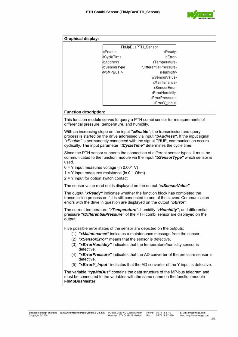
Graphical display:
Function description:
This function module serves to query a PTH combi sensor for measurements of differential pressure, temperature, and humidity.
With an increasing slope on the input "xEnable", the transmission and query process is started on the drive addressed via input "bAddress". If the input signal "xEnable" is permanently connected with the signal TRUE, communication occurs cyclically. The input parameter “tCycleTime“ determines the cycle time.
Since the PTH sensor supports the connection of different sensor types, it must be communicated to the function module via the input "bSensorType" which sensor is used. 0 = Y input measures voltage (in 0.001 V) 1 = Y input measures resistance (in 0.1 Ohm) 2 = Y input for option switch contact
The sensor value read out is displayed on the output "wSensorValue".
The output “xReady“ indicates whether the function block has completed the transmission process or if it is still connected to one of the slaves. Communication errors with the drive in question are displayed on the output "bError".
The current temperature "rTemperature". humidity "rHumidity", and differential pressure "rDifferentialPressure" of the PTH combi sensor are displayed on the output.
Five possible error states of the sensor are depicted on the outputs: (1) "xMaintenance" indicates a maintenance message from the sensor. (2) "xSensorError" means that the sensor is defective. (3) "xErrorHumidity" indicates that the temperature/humidity sensor is
defective. (4) "xErrorPressure" indicates that the AD converter of the pressure sensor is
defective. (5) "xErrorY_Input" indicates that the AD converter of the Y input is defective.
The variable "typMpBus" contains the data structure of the MP-bus telegram and must be connected to the variables with the same name on the function module FbMpBusMaster.
Subject to design changes WAGO Kontakttechnik GmbH & Co. KG PO Box 2880 • D-32385 Minden Phone: 05 71 / 8 87-0 E-Mail: [email protected] Copyright © 2008 Hansastr. 27 • D-32423 Minden Fax.: 05 71 / 8 87-169 Web: http://www.wago.com
25
Signal transmitter UST-3 (FbMpBus_UST3)
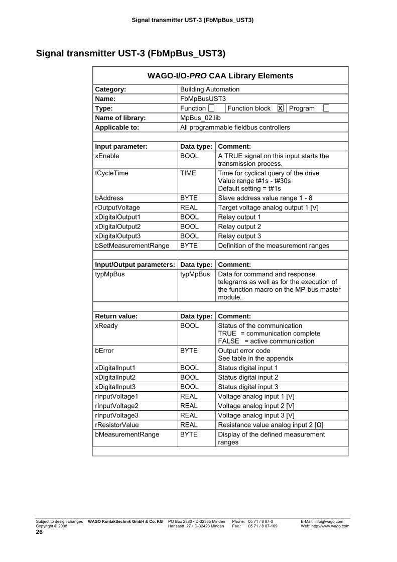
Signal transmitter UST-3 (FbMpBus_UST3)
WAGO-I/O-PRO CAA Library Elements Category: Building Automation Name: FbMpBusUST3 Type: Function Function block X Program Name of library: MpBus_02.lib Applicable to: All programmable fieldbus controllers Input parameter: Data type: Comment: xEnable BOOL A TRUE signal on this input starts the
transmission process. tCycleTime TIME Time for cyclical query of the drive
Value range t#1s - t#30s Default setting = t#1s
bAddress BYTE Slave address value range 1 - 8 rOutputVoltage REAL Target voltage analog output 1 [V] xDigitalOutput1 BOOL Relay output 1 xDigitalOutput2 BOOL Relay output 2 xDigitalOutput3 BOOL Relay output 3 bSetMeasurementRange BYTE Definition of the measurement ranges Input/Output parameters: Data type: Comment: typMpBus typMpBus Data for command and response
telegrams as well as for the execution of the function macro on the MP-bus master module.
Return value: Data type: Comment: xReady BOOL Status of the communication
TRUE = communication complete FALSE = active communication
bError BYTE Output error code See table in the appendix
xDigitalInput1 BOOL Status digital input 1 xDigitalInput2 BOOL Status digital input 2 xDigitalInput3 BOOL Status digital input 3 rInputVoltage1 REAL Voltage analog input 1 [V] rInputVoltage2 REAL Voltage analog input 2 [V] rInputVoltage3 REAL Voltage analog input 3 [V] rResistorValue REAL Resistance value analog input 2 [Ω] bMeasurementRange BYTE Display of the defined measurement
ranges
Subject to design changes WAGO Kontakttechnik GmbH & Co. KG PO Box 2880 • D-32385 Minden Phone: 05 71 / 8 87-0 E-Mail: [email protected] Copyright © 2008 Hansastr. 27 • D-32423 Minden Fax.: 05 71 / 8 87-169 Web: http://www.wago.com 26

Signal transmitter UST-3 (FbMpBus_UST3)
Graphical illustration:
Function description:
This module serves the purpose of communication with the signal transmitter UST-3.
With an increasing slope on the input "xEnable", the transmission and query process is started on the drive addressed via input "bAddress". If the input signal "xEnable" is permanently connected with the signal TRUE, communication occurs cyclically. The input parameter “tCycleTime“ determines the cycle time.
The input "rOutputVoltage" specifies the voltage for the analog output.
Via the inputs "xDigitalOutput1", "xDigitalOutput2", and "xDigitalOutput3" it is possible to control the three relays on the UST-3 device.
Since the UST3 signal transmitter supports different measurement ranges, the measurement range of the analog inputs is defined via the input "bSetMeasurementRange" and for checking it is displayed on the output "bMeasurementRange".
Bit 0 = 0 -> voltage analog channel 1 (0..11 V) Bit 0 = 1 -> voltage analog channel 1 (0..3 V)
Bit 1 = 0 -> voltage analog channel 2 (0..11 V) Bit 1 = 1 -> voltage analog channel 2 (0..3 V)
Bit 3.2 = 01 -> resistance value range (0..5 kOhm) Bit 3.2 = 00 -> resistance value range (0..20 kOhm) Bit 3.2 = 10 -> resistance value range (0..262 kOhm)
Bit 4 = 0 -> voltage analog channel 3 (0..11 V) Bit 4 = 1 -> voltage analog channel 3 (0..3 V)
Bit 7 = 0 -> no resistance measurement Bit 7 = 1 -> voltage source for resistance measurement
The output “xReady“ indicates whether the function block has completed the transmission process or if it is still connected to one of the slaves. Communication errors with the drive in question are displayed on the output "bError".
The status or measurement values of the digital and analog inputs are displayed on the outputs "xDigitalInput1", "xDigitalInput2", "xDigitalInput3", "rInputVoltage1", "rInputVoltage2", "rInputVoltage3", and "rResistorValue".
The variable "typMpBus" contains the data structure of the MP-bus telegram and must be connected to the variables with the same name on the function module FbMpBusMaster.
Subject to design changes WAGO Kontakttechnik GmbH & Co. KG PO Box 2880 • D-32385 Minden Phone: 05 71 / 8 87-0 E-Mail: [email protected] Copyright © 2008 Hansastr. 27 • D-32423 Minden Fax.: 05 71 / 8 87-169 Web: http://www.wago.com
27
NI 1000, Ni1000L&S, PT1000, and NTC5K (e. g. Fu_NI1000)
Resistance characteristic curves
NI 1000, Ni1000L&S, PT1000, and NTC5K (e. g. Fu_NI1000)
WAGO-I/O-PRO CAA Library Elements Category: Building Automation Name: Fu_NI1000
Fu_NI100_LuS Fu_NTC5K Fu_PT1000
Type: Function X Function block Program Name of library: MpBus_02.lib Applicable to: All programmable fieldbus controllers Input parameter: Data type: Comment: wOhm WORD Measurement value of the connected
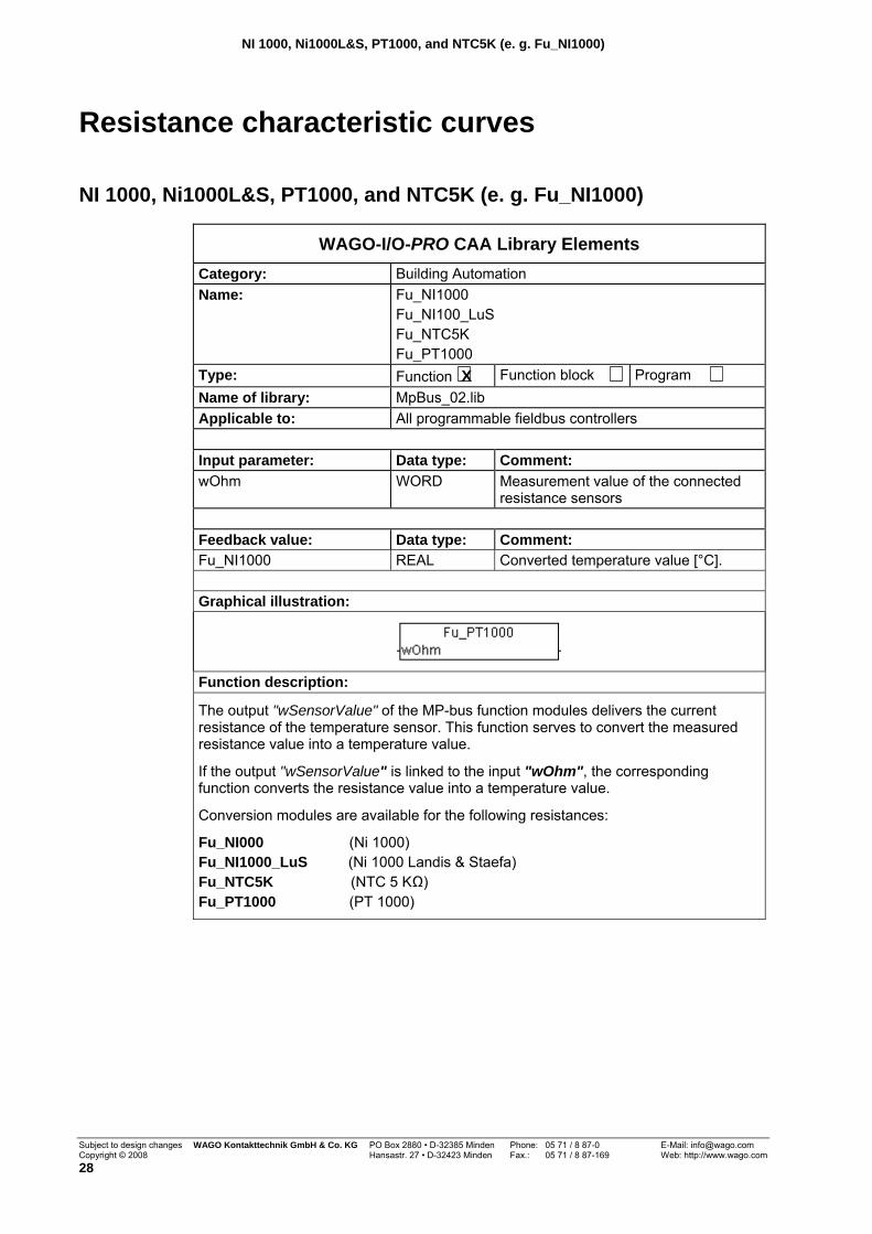
resistance sensors Feedback value: Data type: Comment: Fu_NI1000 REAL Converted temperature value [°C]. Graphical illustration:
Function description:
The output "wSensorValue" of the MP-bus function modules delivers the current resistance of the temperature sensor. This function serves to convert the measured resistance value into a temperature value.
If the output "wSensorValue" is linked to the input "wOhm", the corresponding function converts the resistance value into a temperature value.
Conversion modules are available for the following resistances:
Fu_NI000 (Ni 1000) Fu_NI1000_LuS (Ni 1000 Landis & Staefa) Fu_NTC5K (NTC 5 KΩ) Fu_PT1000 (PT 1000)
Subject to design changes WAGO Kontakttechnik GmbH & Co. KG PO Box 2880 • D-32385 Minden Phone: 05 71 / 8 87-0 E-Mail: [email protected] Copyright © 2008 Hansastr. 27 • D-32423 Minden Fax.: 05 71 / 8 87-169 Web: http://www.wago.com 28
Error codes
Appendix
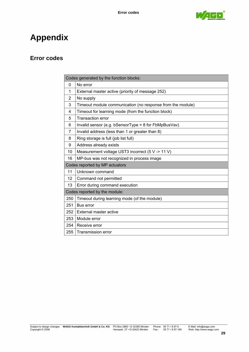
Error codes
Codes generated by the function blocks:
0 No error 1 External master active (priority of message 252) 2 No supply 3 Timeout module communication (no response from the module) 4 Timeout for learning mode (from the function block) 5 Transaction error 6 Invalid sensor (e.g. bSensorType = 8 for FbMpBusVav) 7 Invalid address (less than 1 or greater than 8) 8 Ring storage is full (job list full) 9 Address already exists 10 Measurement voltage UST3 incorrect (5 V -> 11 V) 16 MP-bus was not recognized in process image
Codes reported by MP actuators 11 Unknown command 12 Command not permitted 13 Error during command execution
Codes reported by the module: 250 Timeout during learning mode (of the module) 251 Bus error 252 External master active 253 Module error 254 Receive error 255 Transmission error
Subject to design changes WAGO Kontakttechnik GmbH & Co. KG PO Box 2880 • D-32385 Minden Phone: 05 71 / 8 87-0 E-Mail: [email protected] Copyright © 2008 Hansastr. 27 • D-32423 Minden Fax.: 05 71 / 8 87-169 Web: http://www.wago.com
29
WAGO Kontakttechnik GmbH & Co. KG PO Box 2880 • D-32385 Minden Hansastraße 27 • D-32423 Minden Phone: +49 (0) 571/8 87 – 0 Fax: +49 (0) 5 71/8 87 – 1 69 E-Mail:[email protected] Internet: http://www.wago.com


