Embed Size (px)
Citation preview
8/21/2019 MR_K2661
http://slidepdf.com/reader/full/mrk2661 1/499
K
2661
Musician’s Reference
©2003 All rights reserved. Kurzweil ® is a product line of Young Chang Co., Ltd. Young Chang®, Kurzweil ® , V. A. S. T. ®, KDFX®,Pitcher®, and LaserVerb®, KSP8 ™, K2661™, K2600™, K2500™, and K2000™ are trademarks of Young Chang Co., Ltd. SmartMedia™ is atrademark of Toshiba Corporation. ADAT® is a registered trademark of Alesis Corporation. All other products and brand names aretrademarks or registered trademarks of their respective companies. Product features and specifications are subject to change without notice.
You may legally print up to two (2) copies of this document for personal use. Commercial use of any copies of this documentis prohibited. Young Chang Co. retains ownership of all intellectual property represented by this document.
Part Number: 910400 Rev. A

8/21/2019 MR_K2661
http://slidepdf.com/reader/full/mrk2661 2/499
ii
IMPORTANT SAFETY & INSTALLATION INSTRUCTIONS
INSTRUCTIONS PERTAINING TO THE RISK OF FIRE, ELECTRIC SHOCK, OR INJURY TO PERSONS
WARNING:
When using electric products, basic precautions shouldalways be followed, including the following:
1. Read all of the Safety and Installation Instructions and Explanationof Graphic Symbols before using the product.
2. This product must be grounded. If it should malfunction or breakdown, grounding provides a path of least resistance for electriccurrent to reduce the risk of electric shock. This product is equippedwith a power supply cord having an equipment-groundingconductor and a grounding plug. The plug must be plugged into anappropriate outlet which is properly installed and grounded inaccordance with all local codes and ordinances.
DANGER:
Improper connection of the equipment-groundingconductor can result in a risk of electric shock. Do not modify the
plug provided with the product - if it will not fit the outlet, have aproper outlet installed by a qualified electrician. Do not use anadaptor which defeats the function of the equipment-groundingconductor. If you are in doubt as to whether the product is properlygrounded, check with a qualified serviceman or electrician.
3.
WARNING:
This product is equipped with an AC input voltageselector. The voltage selector has been factory set for the mainssupply voltage in the country where this unit was sold. Changingthe voltage selector may require the use of a different power supplycord or attachment plug, or both. To reduce the risk of fire orelectric shock, refer servicing to qualified maintenance personnel.
4. Do not use this product near water - for example, near a bathtub,washbowl, kitchen sink, in a wet basement, or near a swimmingpool, or the like.
5. This product should only be used with a stand or cart that isrecommended by the manufacturer.
6. This product, either alone or in combination with an amplifier andspeakers or headphones, may be capable of producing soundlevels that could cause permanent hearing loss. Do not operate fora long period of time at a high volume level or at a level that isuncomfortable. If you experience any hearing loss or ringing in theears, you should consult an audiologist.
7. The product should be located so that its location or position doesnot interfere with its proper ventilation.
8. The product should be located away from heat sources such asradiators, heat registers, or other products that produce heat.
9. The product should be connected to a power supply only of the typedescribed in the operating instructions or as marked on the product.
10. This product may be equipped with a polarized line plug (one bladewider than the other). This is a safety feature. If you are unable toinsert the plug into the outlet, contact an electrician to replace yourobsolete outlet. Do not defeat the safety purpose of the plug.
11. The power supply cord of the product should be unplugged from theoutlet when left unused for a long period of time. When unpluggingthe power supply cord, do not pull on the cord, but grasp it by theplug.
12. Care should be taken so that objects do not fall and liquids are notspilled into the enclosure through openings.
13. The product should be serviced by qualified service personnelwhen:
A. The power supply cord or the plug has been damaged;
B. Objects have fallen, or liquid has been spilled into the product;
C. The product has been exposed to rain;
D. The product does not appear to be operating normally orexhibits a marked change in performance;
E. The product has been dropped, or the enclosure damaged.
14. Do not attempt to service the product beyond that described in theuser maintenance instructions. All other servicing should bereferred to qualified service personnel.
15.
WARNING:
Do not place objects on the product's power supplycord, or place the product in a position where anyone could tripover, walk on, or roll anything over cords of any type. Do not allowthe product to rest on or be installed over cords of any type.Improper installations of this type create the possibility of a firehazard and/or personal injury.
RADIO AND TELEVISION INTERFERENCE
WARNING:
Changes or modifications to this instrument not expresslyapproved by Young Chang could void your authority to operate theinstrument.
IMPORTANT:When connecting this product to accessories and/or otherequipment use only high quality shielded cables.
NOTE: This instrument has been tested and found to comply with the
limits for a Class B digital device, pursuant to Part 15 of the FCC Rules.These limits are designed to provide reasonable protection againstharmful interference in a residential installation. This instrumentgenerates, uses, and can radiate radio frequency energy and, if notinstalled and used in accordance with the instructions, may causeharmful interference to radio communications. However, there is noguarantee that interference will not occur in a particular installation. Ifthis instrument does cause harmful interference to radio or televisionreception, which can be determined by turning the instrument off and on,the user is encouraged to try to correct the interference by one or moreof the following measures:
• Reorient or relocate the receiving antenna.
• Increase the separation between the instrument and the receiver.
• Connect the instrument into an outlet on a circuit other than the oneto which the receiver is connected.
• If necessary consult your dealer or an experienced radio/televisiontechnician for additional suggestions.
NOTICE
This apparatus does not exceed the Class B limits for radio noiseemissions from digital apparatus set out in the Radio InterferenceRegulations of the Canadian Department of Communications.
AVIS
Le present appareil numerique n’emet pas de bruits radioelectriquesdepassant les limites applicables aux appareils numeriques de laclass B prescrites dans le Reglement sur le brouillage radioelectriqueedicte par le ministere des Communications du Canada.
SAVE THESE INSTRUCTIONS
The lightning flash with the arrowhead symbol,
within an equilateral triangle, is intended to alert
the user to the presence of uninsulated
"dangerous voltage" within the product's
enclosure that may be of sufficient magnitude
to constitute a risk of electric shock to persons.
RISK OF ELECTRIC SHOCK
DO NOT OPEN
CAUTION: TO REDUCE THE RISK OF ELECTRIC SHOCK,
DO NOT REMOVE THE COVER
NO USER SERVICEABLE PARTS INSIDE
REFER SERVICING TO QUALIFIED SERVICE PERSONNEL
The exclamation point within an equilateral
triangle is intended to alert the user to the
presence of important operating and
maintenance (servicing) instructions in the
literature accompanying the product.
CAUTION
8/21/2019 MR_K2661
http://slidepdf.com/reader/full/mrk2661 3/499
iii
Important Safety Instructions
1) Read these instructions
2) Keep these instructions.
3) Heed all warnings.
4) Follow all instructions.
5) Do not use this apparatus near water.
6) Clean only with dry cloth.
7) Do not block any of the ventilation openings. Install in accordance with the manufacturer’sinstructions.
8) Do not install near any heat sources such as radiators, heat registers, stoves, or other appara-tus (including amplifiers) that produce heat.
9) Do not defeat the safety purpose of the polarized or grounding-type plug. A polarized plughas two blades with one wider than the other. A grounding type plug has two blades and athird grounding prong. The wide blade or the third prong are provided for your safety. If theprovided plug does not fit into your outlet, consult an electrician for replacement of the obso-lete outlet.
10) Protect the power cord from being walked on or pinched, particularly atplugs, convenience receptacles, and the point where they exit from the appa-ratus.
11) Only use attachments/accessories specified by the manufacturer.
12) Use only with a cart, stand, tripod, bracket, or table specified by the manu-facturer, or sold with the apparatus. When a cart is used, use caution whenmoving the cart/apparatus combination to avoid injury from tip-over.
13) Unplug this apparatus during lightning storms or when unused for long periods of time.
14) Refer all servicing to qualified service personnel. Servicing is required when the apparatushas been damaged in any way, such as power-supply cord or plug is damaged, liquid has been spilled or objects have fallen into the apparatus, the apparatus has been exposed to rainor moisture, does not operate normally, or has been dropped.
Warning
- To reduce the risk of fire or electric shock, do not expose this apparatus to rain or mois-ture. Do not expose this equipment to dripping or splashing and ensure that no objects filled with
liquids, such as vases, are placed on the equipment.To completely disconnect this equipment from the AC Mains, disconnect the power supply cordplug from the AC receptacle.

8/21/2019 MR_K2661
http://slidepdf.com/reader/full/mrk2661 4/499
iv
Kurzweil International Contacts
Contact the nearest Kurzweil of fice listed below to locate your local Kurzweil representative.
Kurzweil Co., Ltd.Daerung Technotown 6th, 306493-6 Gasan, Gumcheon, Seoul, KoreaTel: (+82) 2-2108-5700Fax: (+82) 2-2108-5729
A N D Music Corp.P.O. Box 99995Lakewood, WA 98499-0995, USATel: (253) 589-3200Fax: (253) 984-0245
Young Chang Canada Corp.250 Victoria Park Ave. Suite # 105Toronto, Ontario Canada M2H 3P7Tel: (905) 948-8052
Team Kurzweil EuropeGl. Donsvej 86000 KoldingPhone: (+45) 75 56 96 44Fax: (+45) 75 56 96 55
Of ficial distributors in other countries are listed on the web site.
World Wide Web Home Page:
http://www.kurzweilmusicsystems.com
8/21/2019 MR_K2661
http://slidepdf.com/reader/full/mrk2661 5/499
Contents
Kurzweil International Contacts............. .............. .............. ............... .............. .............. .............. .............. .............. ....... iv
World Wide Web Home Page: ............ ............... .............. .............. .............. .............. ............... .............. .............. ........... iv
Chapter 1 Front Panel
Front Panel Quick Reference ......................................................................................................................................... 1-1Volume Knob/ Slider .............................................................................................................................................. 1-1Mode Buttons.......... ............... .............. .............. .............. .............. .............. ............... .............. .............. .............. .... 1-1Chan/Bank Buttons................................................................................................................................................. 1-1Edit Button................................................................................................................................................................ 1-1Soft Buttons............................................................................................................................................................... 1-2Exit Button.......... ............... .............. .............. .............. .............. .............. ............... .............. .............. .............. ......... 1-2Cursor Buttons.......... ............... .............. .............. .............. .............. .............. ............... .............. .............. .............. .. 1-2Alpha Wheel ............................................................................................................................................................. 1-2
Plus / Minus Buttons (- and +) .............................................................................................................................. 1-2Alphanumeric Buttonpad....................................................................................................................................... 1-2The Display............................................................................................................................................................... 1-3Solo Button................................................................................................................................................................ 1-3Mixdown Button ...................................................................................................................................................... 1-3MIDI Faders button ................................................................................................................................................. 1-4Assignable Controllers (Buttons 1–8 and Sliders A–H).................... .............. .............. .............. .............. .......... 1-4PSw1, PSw2 (Buttons 9 and 10)...... .............. .............. .............. ............... .............. .............. .............. .............. ....... 1-4Record, Play/Pause, Stop ....................................................................................................................................... 1-4
Special Button Functions................................................................................................................................................ 1-4Special Button Functions: Double Button Presses .............. .............. ............... .............. .............. .............. .............. ... 1-6
Chapter 2 LFOs
LFO Shapes ...................................................................................................................................................................... 2-1
Chapter 3 DSP Algorithms
Chapter 4 Control Sources
Control Source Lists........................................................................................................................................................ 4-3Descriptions of Control Sources................ ............... .............. .............. .............. .............. ............... .............. .............. .. 4-4MIDI Control Source List ............................................................................................................................................... 4-5Main Control Source List ............................................................................................................................................... 4-8Constant Control Sources......... .............. .............. .............. .............. ............... .............. .............. .............. .............. ..... 4-15
Keyboard Shortcuts for Control Sources ................................................................................................................... 4-16
Chapter 5 MIDI Note Numbers
K2661 Note Numbers and MIDI Note Numbers................. .............. .............. .............. .............. ............... .............. .. 5-1Note Numbers for Percussion Keymaps ..................................................................................................................... 5-1
5-Octave Percussion Keymaps (Range: C2–C7)............. .............. .............. ............... .............. .............. .............. 5-22-Octave Percussion Keymaps (Range: C3 - C5) ................................................................................................ 5-3
8/21/2019 MR_K2661
http://slidepdf.com/reader/full/mrk2661 6/499
K2661 Musician’s Reference
vi
Chapter 6 MIDI, SCSI, and Sample Dumps
SCSI Guidelines ............................................................................................................................................................... 6-1Disk Size Restrictions .............................................................................................................................................. 6-1Configuring a SCSI Chain....................................................................................................................................... 6-1
K2661 and Macintosh Computers 6-3
The MIDI Sample Dump Standard....... .............. .............. .............. .............. ............... .............. .............. .............. ....... 6-4Loading Samples with the MIDI Standard Sample Dump .............. .............. .............. .............. .............. .......... 6-4Getting a Sample into a Sample Editor from the K2661.............. .............. .............. ............... .............. .............. 6-5Loading a Sample into the K2661 from another K2661 ............. .............. .............. .............. .............. ............... .. 6-5Dumping from the K2661 to a Sampler................................................................................................................ 6-5Dumping a Sample from the K2661 to a MIDI Data Recorder............ ............... .............. .............. .............. ..... 6-5Loading a Sample into the K2661 from a MIDI Data Recorder................... .............. .............. .............. ............ 6-5Accessing a New K2661 Sample ............................................................................................................................ 6-6Troubleshooting a MIDI Sample Dump ............................................................................................................... 6-6Aborting a MIDI Sample Dump ............................................................................................................................ 6-7
SMDI Sample Transfers .............. .............. .............. ............... .............. .............. .............. .............. ............... .............. .... 6-8
Chapter 7 System Exclusive Protocol
K2661 System Exclusive Implementation.............. ............... .............. .............. .............. .............. ............... .............. .. 7-1Common Format...................................................................................................................................................... 7-1Messages.................................................................................................................................................................... 7-3Master Parameters ................................................................................................................................................... 7-7Button Press Equivalence Tables...... .............. .............. .............. ............... .............. .............. .............. .............. ..... 7-7
Chapter 8 Maintenance and Troubleshooting
Preventive Maintenance............. .............. .............. .............. ............... .............. .............. .............. .............. ............... .... 8-1Cleaning Your K2661 ............................................................................................................................................... 8-1
Battery Replacement....................................................................................................................................................... 8-2Scanner Diagnostics........................................................................................................................................................ 8-3Maximizing Music and Minimizing Noise........ .............. .............. .............. .............. .............. ............... .............. ....... 8-3
Ground Hum ............................................................................................................................................................ 8-4Power Problems and Solutions ..................................................................................................................................... 8-5Troubleshooting............. .............. .............. .............. ............... .............. .............. .............. .............. ............... .............. .... 8-5
Other Possible Problems ......................................................................................................................................... 8-6
Chapter 9 Upgrading Sample Memory
Program RAM vs. Sample RAM................................................................................................................................... 9-1Viewing RAM Objects ............................................................................................................................................. 9-2
Choosing and Installing a SIMM for K2661 Sample Memory............. .............. ............... .............. .............. ............ 9-2SIMM Specifications ................................................................................................................................................ 9-2Installing Sample RAM ........................................................................................................................................... 9-3
Chapter 10 KDFX Reference
In This Chapter.............................................................................................................................................................. 10-1KDFX Algorithms.......................................................................................................................................................... 10-2FX Presets ....................................................................................................................................................................... 10-3KDFX Studios.......... ............... .............. .............. .............. .............. ............... .............. .............. .............. .............. ......... 10-5KDFX Algorithm Specifications.................................................................................................................................. 10-6
8/21/2019 MR_K2661
http://slidepdf.com/reader/full/mrk2661 7/499
K2661 Musician’s Reference
vii
Chapter 11 Glossary
Chapter 12 Triple Modular Processing
Overview ........................................................................................................................................................................ 12-1Triples and Polyphony .......................................................................................................................................... 12-2Soloing and Muting............................................................................................................................................... 12-2KB3 Programs......................................................................................................................................................... 12-2Live Mode ............................................................................................................................................................... 12-2Algorithms for Triple Modular Processing ........................................................................................................ 12-3Compatibility with Other Kurzweil Instruments........ ............... .............. .............. .............. .............. .............. . 12-3
Creating Triples ............................................................................................................................................................. 12-4Editing Triples.................. .............. ............... .............. .............. .............. .............. ............... .............. .............. .............. 12-5
Amplitude Envelopes............................................................................................................................................ 12-6Other Considerations ............................................................................................................................................ 12-9
Algorithm Reference................................................................................................................................................... 12-12K2661 Triple Programs: Controller Assignments ............. .............. .............. ............... .............. .............. .............. . 12-36
Alphanumeric Buttonpad Entries for DSP Functions.................. .............. .............. .............. .............. ............... ... 12-39Special Cases......................................................................................................................................................... 12-39
Appendix A Specifications
K2661 Features............. .............. .............. .............. .............. ............... .............. .............. .............. .............. ............... ..... A-1Environmental Specifications .......................................................................................................................................A-2
Temperature Ranges .............. ............... .............. .............. .............. .............. .............. ............... .............. .............. . A-2Relative Humidity Ranges (Non-condensing)............. ............... .............. .............. .............. .............. .............. .. A-2
Physical Specifications................................................................................................................................................... A-2Electrical Specifications .................................................................................................................................................A-2
Safe Voltage Ranges ............. .............. ............... .............. .............. .............. .............. .............. ............... .............. ... A-3Analog Audio Specifications ........................................................................................................................................ A-3
Audio Jacks.............................................................................................................................................................. A-3Separate Outputs...... ............... .............. .............. .............. .............. .............. ............... .............. .............. .............. . A-3Mix Outputs.............................................................................................................................................................A-3Headphone Output................................................................................................................................................. A-3
MIDI Implementation Chart...... .............. .............. ............... .............. .............. .............. .............. .............. ............... ... A-4
Appendix B SysEx Control of KDFX
SysEx Message Structure................................................................................................................................................B-1Header .......................................................................................................................................................................B-1Body ...........................................................................................................................................................................B-2End .............................................................................................................................................................................B-2
Device Codes....................................................................................................................................................................B-3
Parameter Codes .............................................................................................................................................................B-3MSB and LSB....................................................................................................................................................................B-4
Appendix C Standard K2661 ROM Objects
Groove Setups...........................................................................................................................................................C-1Special Purpose Setups............................................................................................................................................C-2QA Banks...................................................................................................................................................................C-3Setups.........................................................................................................................................................................C-4Songs..........................................................................................................................................................................C-5Programs ............ ............... .............. .............. .............. .............. ............... .............. .............. .............. .............. .........C-6
8/21/2019 MR_K2661
http://slidepdf.com/reader/full/mrk2661 8/499
K2661 Musician’s Reference
viii
Appendix D Contemporary ROM Block Objects
Programs............. ............... .............. .............. .............. .............. .............. ............... .............. .............. .............. .............. . D-2Keymaps .......................................................................................................................................................................... D-3Program Control Assignments .............. .............. .............. .............. .............. ............... .............. .............. .............. ...... D-4
Controller Assignments: Contemporary ROM Block ............................................................................................... D-7Secondary Effects .................................................................................................................................................... D-7Program Control Assignments.............. .............. .............. .............. ............... .............. .............. .............. ............. D-8Setup Control Assignments ................................................................................................................................. D-17
Appendix E Orchestral ROM Block Objects
Programs...........................................................................................................................................................................E-2Keymaps ...........................................................................................................................................................................E-3Program Control Assignments......................................................................................................................................E-4Controller Assignments: Orchestral ROM Block........................................................................................................E-7
Secondary Effects ............ ............... .............. .............. .............. .............. .............. ............... .............. .............. ......... E-7
Appendix F SD Piano ROM Option
SmartMedia Contents ............ ............... .............. .............. .............. .............. .............. ............... .............. .............. ......... F-1Sympathetic Vibrations .................................................................................................................................................. F-1
Modifying SD Piano Programs .............................................................................................................................. F-1Controller Assignments for SD Piano Programs .............. .............. .............. ............... .............. .............. .............. ..... F-2
Appendix G Vintage Electric Pianos ROM Option
Fender Rhodes......................................................................................................................................................... G-3Wurlitzer................ .............. .............. .............. .............. ............... .............. .............. .............. .............. .............. ...... G-3Hohner Pianet.......................................................................................................................................................... G-3Yamaha CP-80................... .............. .............. .............. .............. ............... .............. .............. .............. .............. ........ G-4RMI Electra-Piano................................................................................................................................................... G-4
Vintage EP Programs ..................................................................................................................................................... G-5Vintage EP Setups ........................................................................................................................................................ G-18Vintage Electric Piano Keymaps ................................................................................................................................ G-20Vintage Electric Piano Samples ............. .............. .............. .............. .............. ............... .............. .............. .............. .... G-20Vintage Electric Piano Studios........ .............. .............. .............. .............. .............. ............... .............. .............. ........... G-20
Appendix H General MIDI
Inside GM Mode.............................................................................................................................................................H-1General MIDI Programs................................................................................................................................................H-2
GM Drum Kits.........................................................................................................................................................H-3Standard Mode Controller Assignments ............. .............. .............. ............... .............. .............. .............. .............. .... H-4
Appendix I Live Mode Objects
Live Mode Programs ....................................................................................................................................................... I-1
Index
8/21/2019 MR_K2661
http://slidepdf.com/reader/full/mrk2661 9/499
Front Panel
Front Panel Quick Reference
1-1
Chapter 1
Front Panel
Front Panel Quick Reference
This section describes the features of the front panel of your K2661.
Volume Knob/ Slider
Controls mixed audio outputs and headphone jack only. Does not send MIDI Volume (MIDI 07).
Mode Buttons
Press any of these eight buttons to enter the corresponding mode.
Chan/Bank Buttons
Scroll through the layers of the current program while in the Program Editor. Scroll through thezones in the current setup while in Setup mode. Scroll through the Quick Access banks while inQuick Access mode.
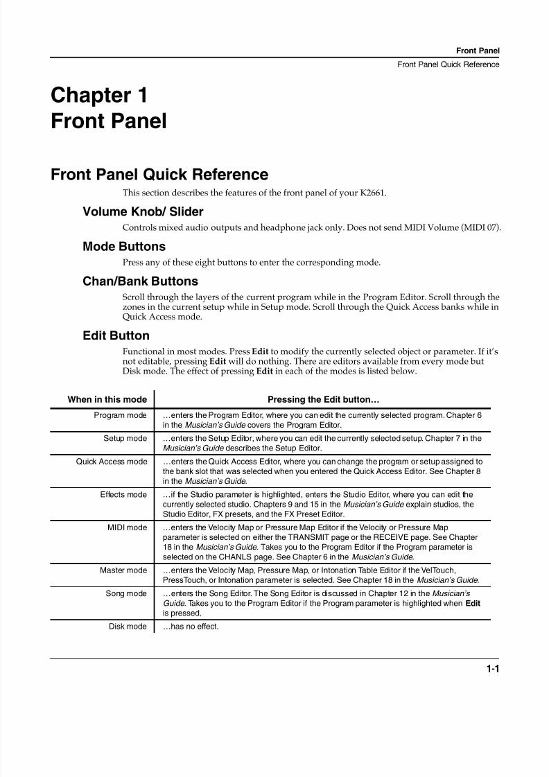
Edit Button
Functional in most modes. Press Edit
to modify the currently selected object or parameter. If it’snot editable, pressing Edit
will do nothing. There are editors available from every mode butDisk mode. The effect of pressing Edit
in each of the modes is listed below.
When in this mode Pressing the Edit button…
Program mode …enters the Program Editor, where you can edit the currently selected program. Chapter 6
in the Musician’s Guide
covers the Program Editor.
Setup mode …enters the Setup Editor, where you can edit the currently selected setup. Chapter 7 in the
Musician’s Guide
describes the Setup Editor.
Quick Access mode …enters the Quick Access Editor, where you can change the program or setup assigned to
the bank slot that was selected when you entered the Quick Access Editor. See Chapter 8
in the Musician’s Guide
.
Effects mode …if the Studio parameter is highlighted, enters the Studio Editor, where you can edit the
currently selected studio. Chapters 9 and 15 in the Musician’s Guide
explain studios, the
Studio Editor, FX presets, and the FX Preset Editor.
MIDI mode …enters the Velocity Map or Pressure Map Editor if the Velocity or Pressure Map
parameter is selected on either the TRANSMIT page or the RECEIVE page. See Chapter
18 in the Musician’s Guide
. Takes you to the Program Editor if the Program parameter isselected on the CHANLS page. See Chapter 6 in the Musician’s Guide
.
Master mode …enters the Velocity Map, Pressure Map, or Intonation Table Editor if the VelTouch,
PressTouch, or Intonation parameter is selected. See Chapter 18 in the Musician’s Guide
.
Song mode …enters the Song Editor. The Song Editor is discussed in Chapter 12 in the Musician’s
Guide
. Takes you to the Program Editor if the Program parameter is highlighted when Edit
is pressed.
Disk mode …has no effect.
8/21/2019 MR_K2661
http://slidepdf.com/reader/full/mrk2661 10/499
1-2
Front Panel
Front Panel Quick Reference
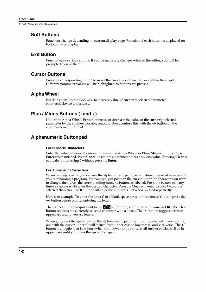
Soft Buttons
Functions change depending on current display page. Function of each button is displayed on bottom line of display.
Exit Button
Press to leave various editors. If you’ve made any changes while in the editor, you will beprompted to save them.
Cursor Buttons
Press the corresponding button to move the cursor up, down, left, or right in the display.Different parameter values will be highlighted as buttons are pressed.
Alpha Wheel
For data entry. Rotate clockwise to increase value of currently selected parameter,counterclockwise to decrease.
Plus / Minus Buttons (- and +)
Under the Alpha Wheel. Press to increase or decrease the value of the currently selectedparameter by the smallest possible amount. Don’t confuse this with the +/-
button on thealphanumeric buttonpad.
Alphanumeric Buttonpad
For Numeric Characters
Enter the value numerically instead of using the Alpha Wheel or Plus
/
Minus
buttons. PressEnter
when finished. Press Cancel
to restore a parameter to its previous value. Pressing Clear
isequivalent to pressing 0
without pressing Enter
.
For Alphabetic Characters
When naming objects, you can use the alphanumeric pad to enter letters instead of numbers. Ifyou’re renaming a program, for example, just position the cursor under the character you wantto change, then press the corresponding numeric button, as labeled. Press the button as manytimes as necessary to enter the desired character. Pressing Clear
will enter a space before theselected character. The 0
button will enter the numerals 0–9 when pressed repeatedly.
Here’s an example. To enter the letter C
in a blank space, press 1
three times. You can press the+/-
button before or after entering the letter.
The Cancel
button is equivalent to the >>>
soft button, and Enter
is the same as OK. The Clear button replaces the currently selected character with a space. The +/– button toggles betweenuppercase and lowercase letters.
When you press the +/– button on the alphanumeric pad, the currently selected character (theone with the cursor under it) will switch from upper case to lower case, and vice versa. The +/– button is a toggle; that is, if you switch from lower to upper case, all further entries will be inupper case until you press the +/– button again.
8/21/2019 MR_K2661
http://slidepdf.com/reader/full/mrk2661 11/499
Front Panel
Front Panel Quick Reference
1-3
There are several punctuation characters available as well, but they can be entered only with theAlpha Wheel or Plus/Minus buttons. The punctuation characters are between z (lower case)and 0.
Special Alphanumeric Buttonpad Functions
When you’re in Quick Access mode, the Alphanumeric buttonpad can be used to select theentries in the current Quick Access bank. The layout of the alphanumeric buttonpadcorresponds to the layout of Quick Access bank entries as seen on the Quick Access-mode page.
There’s also a shortcut for selecting different QA banks while in QA mode. Just press the +/– orClear button on the alphanumeric pad, and you’ll be prompted to enter a bank number. Typethe desired number on the alphanumeric pad, then press Enter. The bank will be selected, andyou’ll return to the Quick Access page.
You can also use the alphanumeric pad to select strings to search for in the currently selected listof objects, and to enter new strings to search for (see the Musician’s Guide.).
The Display
You may want to adjust the contrast and brightness of the display for different lightingconditions. There are two adjustment knobs on the rear panel of the K2661.
Solo ButtonMutes all zones in setup except the current one. The button of the zone being soloed glows red.
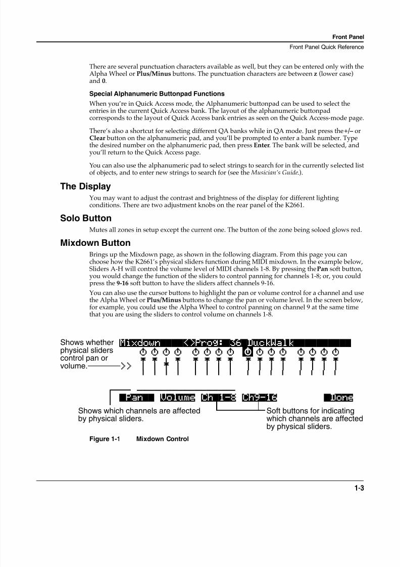
Mixdown ButtonBrings up the Mixdown page, as shown in the following diagram. From this page you canchoose how the K2661’s physical sliders function during MIDI mixdown. In the example below,Sliders A-H will control the volume level of MIDI channels 1-8. By pressing the Pan soft button,you would change the function of the sliders to control panning for channels 1-8; or, you couldpress the 9-16 soft button to have the sliders affect channels 9-16.
You can also use the cursor buttons to highlight the pan or volume control for a channel and usethe Alpha Wheel or Plus/Minus buttons to change the pan or volume level. In the screen below,for example, you could use the Alpha Wheel to control panning on channel 9 at the same timethat you are using the sliders to control volume on channels 1-8.
Figure 1-1 Mixdown Control
Mixdown||||<>Prog:|36|DuckWalk|||||||||| WXWXWXWX WXWXWXWX WXWXWXWX WXWXWXWX
wxwxCwx wxwxwxwx wxwxwxwx wxwxwxwx >> z z~ z z z z z z z z z z z z z
_ _ _ _ _ _ _ _ _ _ _ _ _ _ _ _
*****************
|Pan|| Volume Ch|1-8 Ch9-16 |DoneShows which channels are affectedby physical sliders.
Soft buttons for indicatingwhich channels are affectedby physical sliders.
Shows whetherphysical sliderscontrol pan orvolume.
8/21/2019 MR_K2661
http://slidepdf.com/reader/full/mrk2661 12/499
1-4
Front Panel
Special Button Functions
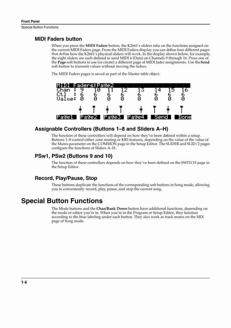
MIDI Faders buttonWhen you press the MIDI Faders button, the K2661’s sliders take on the functions assigned onthe current MIDI Faders page. From the MIDI Faders display you can define four different pagesthat define how the K2661’s physical sliders will work. In the display shown below, for example,
the eight sliders are each defined to send MIDI 6 (Data) on Channels 9 through 16. Press one ofthe Page soft buttons to use (or create) a different page of MIDI fader assignments. Use the Sendsoft button to transmit values without moving the faders.
The MIDI Faders pages is saved as part of the Master table object.
Assignable Controllers (Buttons 1–8 and Sliders A–H)The function of these controllers will depend on how they’ve been defined within a setup.Buttons 1–8 control either zone muting or KB3 features, depending on the value of the value ofthe Mutes parameter on the COMMON page in the Setup Editor. The SLIDER and SLID/2 pagesconfigure the functions of Sliders A–H.
PSw1, PSw2 (Buttons 9 and 10)The function of these controllers depends on how they’ve been defined on the SWITCH page inthe Setup Editor.
Record, Play/Pause, StopThese buttons duplicate the functions of the corresponding soft buttons in Song mode, allowingyou to conveniently record, play, pause, and stop the current song.
Special Button FunctionsThe Mode buttons and the Chan/Bank Down button have additional functions, depending onthe mode or editor you’re in. When you’re in the Program or Setup Editor, they functionaccording to the blue labeling under each button. They also work as track mutes on the MIXpage of Song mode.
MIDI|Faders:Page2|||||||||||||||||||||||Chan : 9 10 11 12 13 14 15 16Ctl : 6 6 6 6 6 6 6 6Value: 0 0 0 0 0 0 0 0
\] ~ \] ~ \] ~ \] ~ _ _ _ _ _ _ _ _
Page1| Page2| Page3| Page4| |Send| |Done
8/21/2019 MR_K2661
http://slidepdf.com/reader/full/mrk2661 13/499
Front Panel
Special Button Functions
1-5
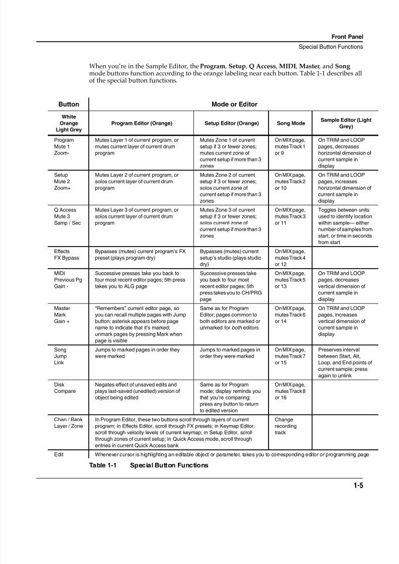
When you’re in the Sample Editor, the Program , Setup , Q Access , MIDI , Master , and Song mode buttons function according to the orange labeling near each button. Table 1-1 describes allof the special button functions.
Button Mode or Editor
White
Orange
Light Grey
Program Editor (Orange) Setup Editor (Orange) Song ModeSample Editor (Light
Grey)
Program
Mute 1
Zoom-
Mutes Layer 1 of current program, or
mutes current layer of current drum
program
Mutes Zone 1 of current
setup if 3 or fewer zones;
mutes current zone of
current setup if more than 3
zones
On MIX page,
mutes Track 1
or 9
On TRIM and LOOP
pages, decreases
horizontal dimension of
current sample in
display
Setup
Mute 2
Zoom+
Mutes Layer 2 of current program, or
solos current layer of current drum
program
Mutes Zone 2 of current
setup if 3 or fewer zones;
solos current zone of
current setup if more than 3
zones
On MIX page,
mutes Track 2
or 10
On TRIM and LOOP
pages, increases
horizontal dimension of
current sample in
display
Q Access
Mute 3
Samp / Sec
Mutes Layer 3 of current program, or
solos current layer of current drum
program
Mutes Zone 3 of current
setup if 3 or fewer zones;
solos current zone of
current setup if more than 3
zones
On MIX page,
mutes Track 3
or 11
Toggles between units
used to identify location
within sample— either
number of samples from
start, or time in seconds
from start
Effects
FX Bypass
Bypasses (mutes) current program’s FX
preset (plays program dry)
Bypasses (mutes) current
setup’s studio (plays studio
dry)
On MIX page,
mutes Track 4
or 12
MIDI
Previous Pg
Gain -
Successive presses take you back to
four most recent editor pages; 5th press
takes you to ALG page
Successive presses take
you back to four most
recent editor pages; 5th
press takes you to CH/PRG
page
On MIX page,
mutes Track 5
or 13
On TRIM and LOOP
pages, decreases
vertical dimension of
current sample in
display
Master
Mark
Gain +
“Remembers” current editor page, so
you can recall multiple pages with Jump
button; asterisk appears before page
name to indicate that it’s marked;
unmark pages by pressing Mark when
page is visible
Same as for Program
Editor; pages common to
both editors are marked or
unmarked for both editors
On MIX page,
mutes Track 6
or 14
On TRIM and LOOP
pages, increases
vertical dimension of
current sample in
display
Song
Jump
Link
Jumps to marked pages in order they
were marked
Jumps to marked pages in
order they were marked
On MIX page,
mutes Track 7
or 15
Preserves interval
between Start, Alt,
Loop, and End points of
current sample; press
again to unlink
Disk
Compare
Negates effect of unsaved edits and
plays last-saved (unedited) version of
object being edited
Same as for Program
mode; display reminds you
that you’re comparing;
press any button to return
to edited version
On MIX page,
mutes Track 8
or 16
Chan / Bank
Layer / Zone
In Program Editor, these two buttons scroll through layers of current
program; in Effects Editor, scroll through FX presets; in Keymap Editor,
scroll through velocity levels of current keymap; in Setup Editor, scroll
through zones of current setup; in Quick Access mode, scroll through
entries in current Quick Access bank
Change
recording
track
Edit Whenever cursor is highlighting an editable object or parameter, takes you to corresponding editor or programming page
Table 1-1 Special Button Functions
8/21/2019 MR_K2661
http://slidepdf.com/reader/full/mrk2661 14/499
1-6
Front Panel
Special Button Functions: Double Button Presses
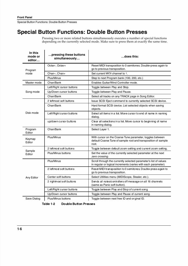
Special Button Functions: Double Button PressesPressing two or more related buttons simultaneously executes a number of special functionsdepending on the currently selected mode. Make sure to press them at exactly the same time.
In thismode or
editor…
…pressing these buttons
simultaneously……does this:
Program
mode
Octav-, Octav+ Reset MIDI transposition to 0 semitones. Double-press again to
go to previous transposition.
Chan–, Chan+ Set current MIDI channel to 1.
Plus/Minus Step to next Program bank (100, 200, etc.)
Master mode Chan/Bank Enables Guitar/Wind Controller mode.
Song mode
Left/Right cursor buttons Toggle between Play and Stop.
Up/Down cursor buttons Toggle between Play and Pause.Chan/Bank Select all tracks on any TRACK page in Song Editor.
Disk mode
2 leftmost soft buttons Issue SCSI Eject command to currently selected SCSI device.
Chan/Bank Hard format SCSI device. List selected objects when saving
objects.
Left/Right cursor buttons Select all items in a list. Move cursor to end of name in naming
dialog.
up/down cursor buttons Clear all selections in a list. Move cursor to beginning of name
in naming dialog.
Program
Editor
Chan/Bank Select Layer 1.
KeymapEditor
Plus/Minus With cursor on the Coarse Tune parameter, toggles between
default Coarse Tune of sample root and transposition of sampleroot.
Sample
Editor
2 leftmost soft buttons Toggle between default zoom setting and current zoom setting.
Plus/Minus buttons Set the value of the currently selected parameter at the next
zero crossing.
Any Editor
Plus/Minus Scroll through the currently selected parameter’s list of values
in regular or logical increments (varies with each parameter).
2 leftmost soft buttons Reset MIDI transposition to 0 semitones. Double-press again to
go to previous transposition.
Center soft buttons Select Utilities menu (MIDIScope, Stealer, etc.).
2 rightmost soft buttons Sends all notes/controllers off message on all 16 channels
(same as Panic soft button).
Left/Right cursor buttons Toggle between Play and Stop of current song.
Up/Down cursor buttons Toggle between Play and Pause of current song.
Save Dialog Plus/Minus buttons Toggle between next free ID and original ID.
Table 1-2 Double Button Presses
8/21/2019 MR_K2661
http://slidepdf.com/reader/full/mrk2661 15/499
LFOs
LFO Shapes
2-1
Chapter 2
LFOs
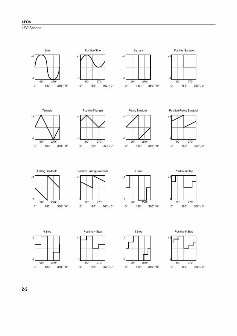
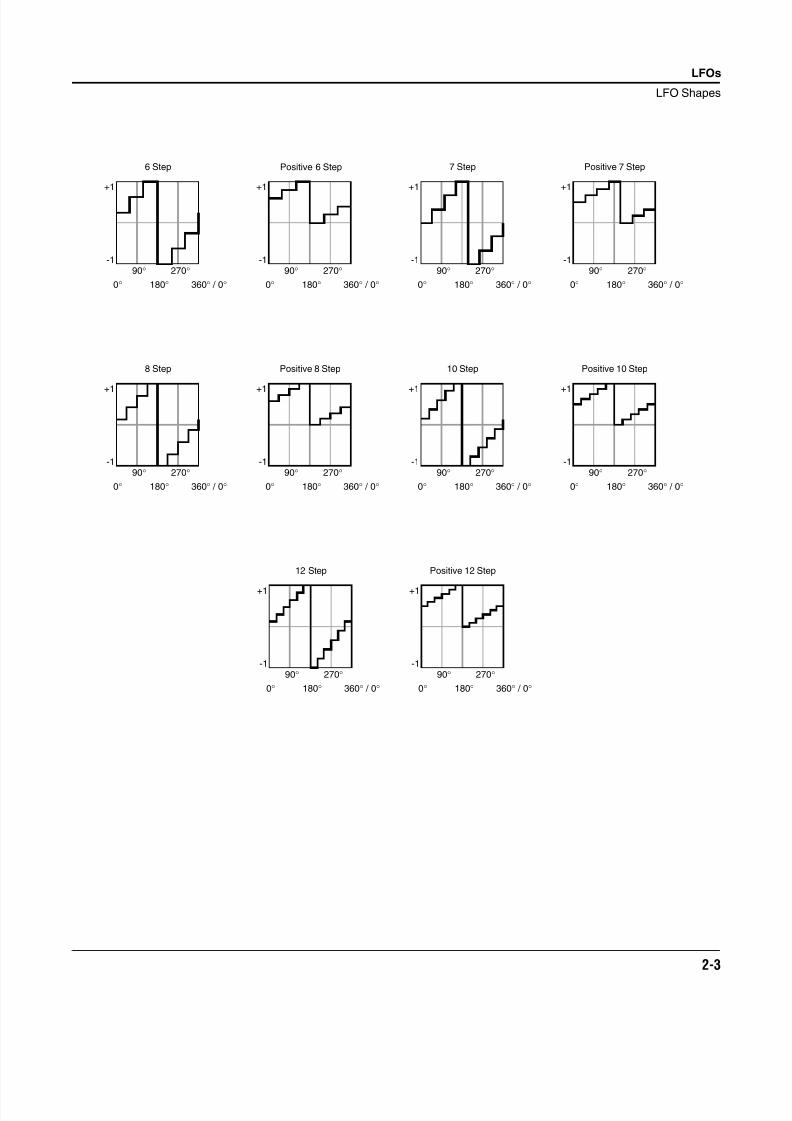
LFO Shapes
LFO Shape Displayed As
Sine Sine
Positive Sine +Sine
Square Square
Positive Square +Squar
Triangle Triang
Positive Triangle +Trian
Rising Sawtooth Rise S
Positive Rising Sawtooth +Rise
Falling Sawtooth Fall S
Positive Falling Sawtooth +Fall
3 Step 3 Step
Positive 3 Step +3 Ste
4 Step 4 Step
Positive 4 step +4 Ste
5 Step 5 Step
Positive 5 Step +5 Ste
6 Step 6 Step
Positive 6 Step +6 Ste
7 Step 7 Step
Positive 7 Step +7 Ste
8 Step 8 Step
Positive 8 Step +8 Ste
10 Step 10 Ste
Positive 10 Step +10 St
12 Step 12 Ste
Positive 12 Step +12 St
8/21/2019 MR_K2661
http://slidepdf.com/reader/full/mrk2661 16/499
2-2
LFOs
LFO Shapes
Sine
+1
-190°
180°
270°
0° 360° / 0°
Positive Sine
+1
-190°
180°
270°
0° 360° / 0°
Sq uare
+1
-190°
180°
270°
0° 360° / 0°
Positive Sq uare
+1
-190°
180°
270°
0° 360° / 0°
Triangle
+1
-190°
180°
270°
0° 360° / 0°
Positive Triangle
+1
-190°
180°
270°
0° 360° / 0°
Rising Sawtooth
+1
-190°
180°
270°
0° 360° / 0°
Positive Rising Sawtooth
+1
-190°
180°
270°
0° 360° / 0°
Falling Sawtooth
+1
-190°
180°
270°
0° 360° / 0°
Positive Falling Sawtooth
+1
-190°
180°
270°
0° 360° / 0°
3 Step
+1
-190°
180°
270°
0° 360° / 0°
Positive 3 Step
+1
-190°
180°
270°
0° 360° / 0°
4 Step
+1
-190°
180°
270°
0° 360° / 0°
Positive 4 Step
+1
-190°
180°
270°
0° 360° / 0°
5 Step
+1
-190°
180°
270°
0° 360° / 0°
Positive 5 Step
+1
-190°
180°
270°
0° 360° / 0°
8/21/2019 MR_K2661
http://slidepdf.com/reader/full/mrk2661 17/499
LFOs
LFO Shapes
2-3
6 Step
+1
-190°
180°
270°
0° 360° / 0°
+1
-190°
180°
270°
0° 360° / 0°
Positive Sine6 Step 7 Step
+1
-190°
180°
270°
0° 360° / 0°
Positive 7 Step
+1
-190°
180°
270°
0° 360° / 0°
8 Step
+1
-190°
180°
270°
0° 360° / 0°
Positive 8 Step
+1
-190°
180°
270°
0° 360° / 0°
10 Step
+1
-190°
180°
270°
0° 360° / 0°
Positive 10 Step
+1
-190°
180°
270°
0° 360° / 0°
12 Step
+1
-190°
180°
270°
0° 360° / 0°
Positive 12 Step
+1
-190°
180°
270°
0° 360° / 0°
8/21/2019 MR_K2661
http://slidepdf.com/reader/full/mrk2661 18/499
2-4
LFOs
LFO Shapes
8/21/2019 MR_K2661
http://slidepdf.com/reader/full/mrk2661 19/499
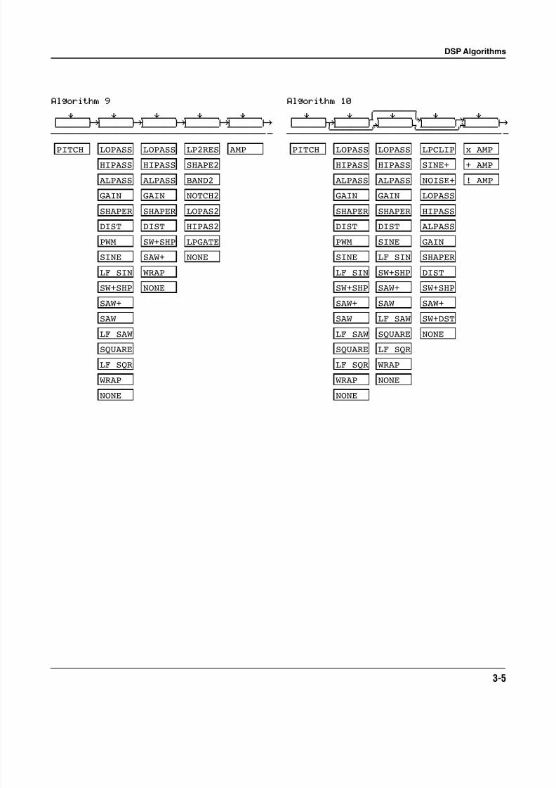
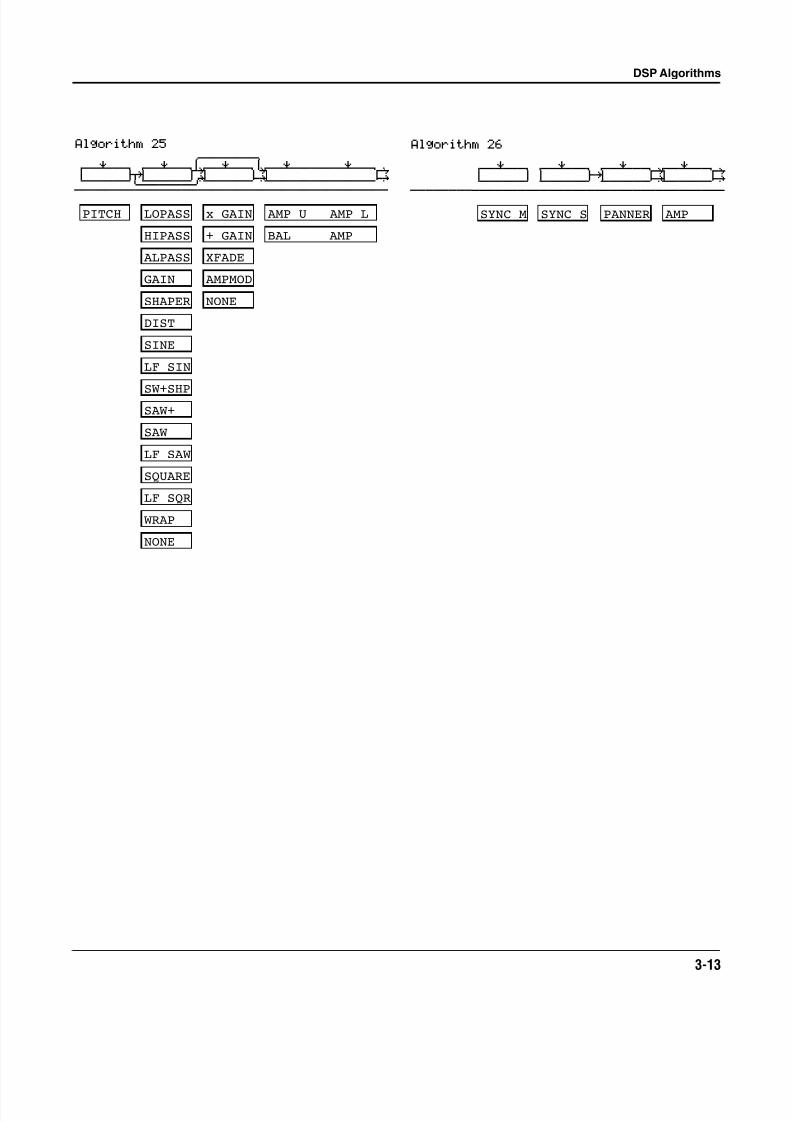
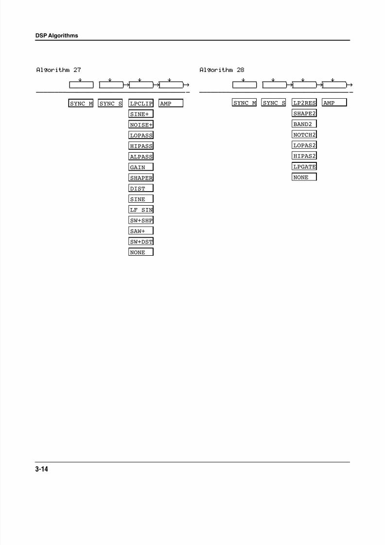
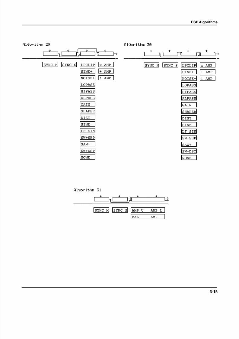
Chapter 3
DSP Algorithms
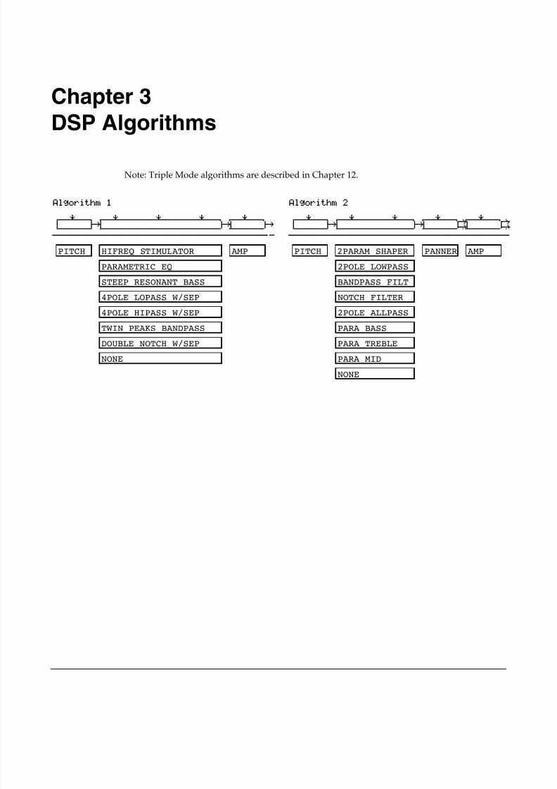
Note: Triple Mode algorithms are described in Chapter 12.
Algorithm 1
errR®rrterrR®rrrrrrR®rrrrrrR®rrterrR®rrt d gk gk ghcvvvvvvbcvvvvvvvvvvvvvvvvvvvvvvbcvvvvvvb|
PITCH HIFREQ STIMULATOR
PARAMETRIC EQ
STEEP RESONANT BASS
4POLE LOPASS W/SEP
4POLE HIPASS W/SEP
TWIN PEAKS BANDPASS
DOUBLE NOTCH W/SEP
NONE
AMP
Algorithm 2
errR®rrterrR®rrrrrrR®rrterrR®rrtYrrR®rrtyd gk gk G; GHcvvvvvvbcvvvvvvvvvvvvvvbcvvvvvvbNvvvvvvbn
PITCH
2POLE LOWPASS
BANDPASS FILT
NOTCH FILTER
2POLE ALLPASS
NONE
AMPPANNER
PARA BASS
PARA TREBLE
PARA MID
2PARAM SHAPER
8/21/2019 MR_K2661
http://slidepdf.com/reader/full/mrk2661 20/499
3-2
DSP Algorithms
Algorithm 3
errR®rrterrR®rrrrrrR®rrtyrrR®rrrrrrR®rrtyd jk u: GH
cvvvvvvm,..............M/vvvvvvvvvvvvvvbn
PITCH
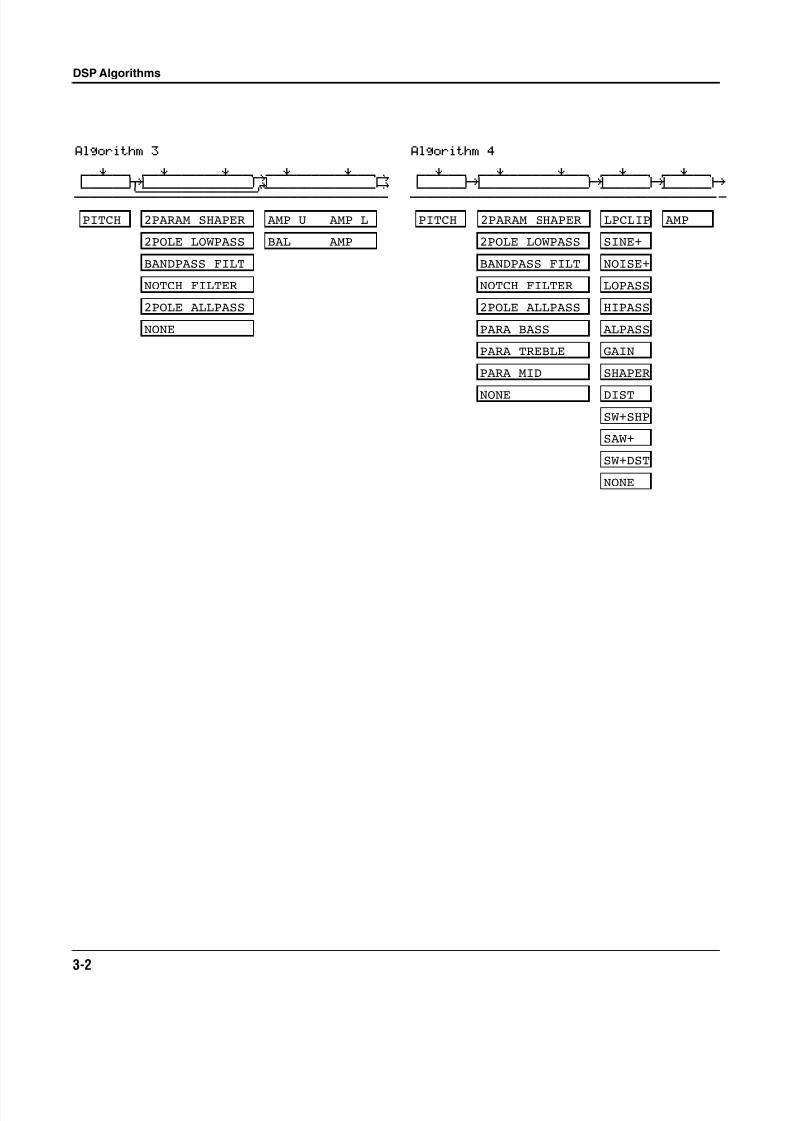
2POLE LOWPASS
BANDPASS FILT
NOTCH FILTER
2POLE ALLPASS
NONE
BAL AMP
AMP U AMP L2PARAM SHAPER
Algorithm 4
errR®rrterrR®rrrrrrR®rrterrR®rrterrR®rrt d gk gk gk gh
cvvvvvvbcvvvvvvvvvvvvvvbcvvvvvvbcvvvvvvb|
PITCH AMP
LOPASS
HIPASS
ALPASS
GAIN
SHAPER
DIST
SW+SHP
SAW+
SW+DST
NONE
2POLE LOWPASS
BANDPASS FILT
NOTCH FILTER
2POLE ALLPASS
NONE
PARA BASS
PARA TREBLE
PARA MID
2PARAM SHAPER LPCLIP
SINE+
NOISE+
8/21/2019 MR_K2661
http://slidepdf.com/reader/full/mrk2661 21/499
DSP Algorithms
3-3
Algorithm 5
errR®rrterrR®rrrrrrR®rrterrR®rrterrR®rrt d gk gk gk ghcvvvvvvbcvvvvvvvvvvvvvvbcvvvvvvbcvvvvvvb|
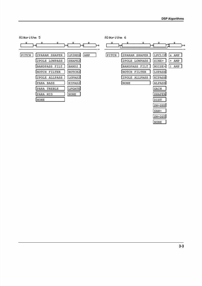
2POLE LOWPASS
BANDPASS FILT
NOTCH FILTER
2POLE ALLPASS
PARA BASS
PARA TREBLE
PARA MID
NONE
PITCH AMP
BAND2
NOTCH2
LOPAS2
HIPAS2
LPGATE
NONE
2PARAM SHAPER
SHAPE2
LP2RES
Algorithm 6
errR®rrterrR®rrrrrrR®rrterrR®rrtYrrR®rrt d jk gk u: ghcvvvvvvm,..............M,......M/vvvvvvb|
PITCH
2POLE LOWPASS
BANDPASS FILT
NOTCH FILTER
2POLE ALLPASS
NONE
LOPASS
HIPASS
ALPASS
GAIN
SHAPER
DIST
SW+SHP
SAW+
SW+DST
NONE
x AMP
+ AMP
! AMP
2PARAM SHAPER LPCLIP
SINE+
NOISE+
8/21/2019 MR_K2661
http://slidepdf.com/reader/full/mrk2661 22/499
3-4
DSP Algorithms
Algorithm 75rrrrrrrr6
errR®rrterrR®rrrrrrR®rrTerrR®rrt7rrR®rrt d jk u? i; ghcvvvvvvm,..............M/vvvvvvbNvvvvvvb|
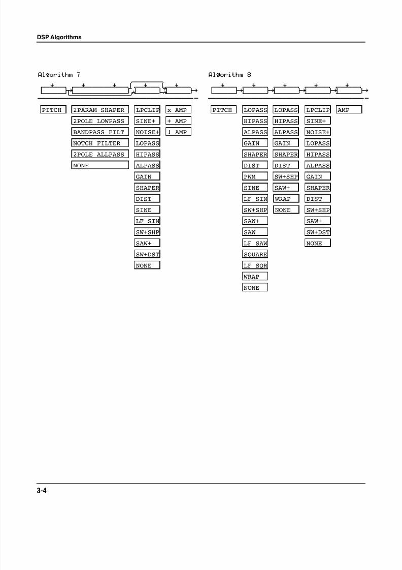
PITCH
2POLE LOWPASS
BANDPASS FILT
NOTCH FILTER
2POLE ALLPASS
NONE
LOPASS
HIPASS
ALPASS
GAIN
SHAPER
DIST
SINE
LF SIN
SW+SHP
SAW+
SW+DST
NONE
x AMP
+ AMP
2PARAM SHAPER LPCLIP
SINE+
NOISE+ ! AMP
Algorithm 8
errR®rrterrR®rrterrR®rrterrR®rrterrR®rrt d gk gk gk gk ghcvvvvvvbcvvvvvvbcvvvvvvbcvvvvvvbcvvvvvvb|
PITCH LOPASS
HIPASS
ALPASS
GAIN
SHAPER
DIST
PWM
SINE
LF SIN
SW+SHP
SAW+
SAW
LF SAW
SQUARE
LF SQR
WRAP
NONE
LOPASS
HIPASS
ALPASS
GAIN
SHAPER
DIST
SW+SHP
SAW+
WRAP
NONE
LOPASS
HIPASS
ALPASS
GAIN
SHAPER
DIST
SW+SHP
SAW+
SW+DST
NONE
AMPLPCLIP
SINE+
NOISE+
8/21/2019 MR_K2661
http://slidepdf.com/reader/full/mrk2661 23/499
DSP Algorithms
3-5
Algorithm 105rrrrrrrr6
errR®rrterrR®rrTerrR®rrt7rrR®rrtYrrR®rrt d jk u? JU u: ghcvvvvvvm,......M/vvvvvvm,......M/vvvvvvb|
PITCH LOPASS
HIPASS
ALPASS
GAIN
SHAPER
DIST
SW+SHP
SAW+
NONE
PWM
SINE
LF SIN
SAW
LF SAW
SQUARE
LF SQR
WRAP
LOPASS
HIPASS
ALPASS
GAIN
SHAPER
DIST
SW+SHPSAW+
NONE
SINE
LF SIN
SAW
LF SAW
SQUARE
LF SQR
WRAP
LOPASS
HIPASS
ALPASS
GAIN
SHAPER
DISTSW+SHP
SAW+
NONE
SW+DST
x AMP
+ AMP
LPCLIP
SINE+
NOISE+ ! AMP
Algorithm 9
errR®rrterrR®rrterrR®rrterrR®rrterrR®rrt d gk gk gk gk ghcvvvvvvbcvvvvvvbcvvvvvvbcvvvvvvbcvvvvvvb|
PITCH AMPLOPASS
HIPASS
ALPASS
GAIN
SHAPER
DIST
SW+SHP
SAW+
NONE
PWM
SINE
LF SIN
SAW
LF SAW
SQUARE
LF SQR
WRAP
LOPASS
HIPASS
ALPASS
GAIN
SHAPER
DIST
SW+SHP
SAW+
NONEWRAP
BAND2
NOTCH2
LOPAS2
HIPAS2
LPGATE
NONE
LP2RES
SHAPE2
8/21/2019 MR_K2661
http://slidepdf.com/reader/full/mrk2661 24/499
3-6
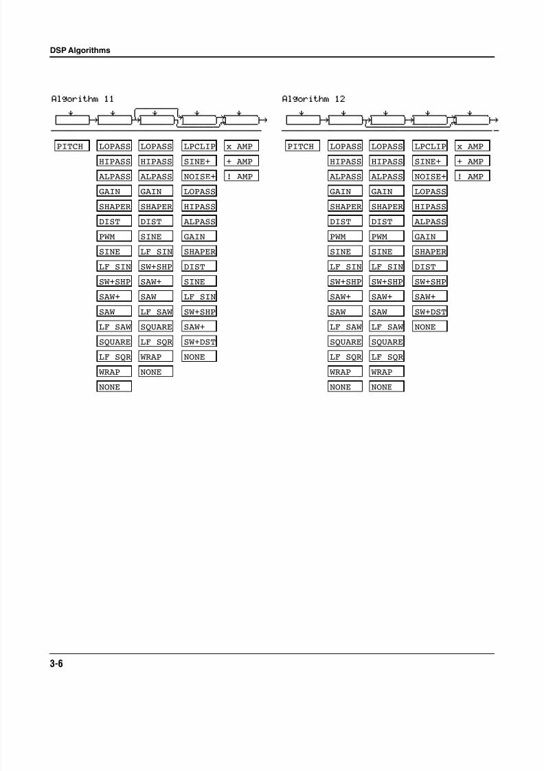
DSP Algorithms
Algorithm 115rrrrrrrr6
errR®rrterrR®rrTerrR®rrt7rrR®rrtYrrR®rrt d gk fk jU u: ghcvvvvvvbcvvvvvvbcvvvvvvm,......M/vvvvvvb
LOPASS
HIPASS
ALPASS
GAIN
SHAPER
DIST
SW+SHP
SAW+
NONE
PWM
SINE
LF SIN
SAW
LF SAW
SQUARE
LF SQR
WRAP
LOPASS
HIPASS
ALPASS
GAIN
SHAPER
DIST
SW+SHPSAW+
NONE
SINE
LF SIN
SAW
LF SAW
SQUARE
LF SQR
WRAP
PITCH
LOPASS
HIPASS
ALPASS
GAIN
SHAPER
DISTSINE
LF SIN
SW+SHP
SAW+
NONE
SW+DST
x AMP
+ AMP
LPCLIP
SINE+
NOISE+ ! AMP
Algorithm 12
errR®rrterrR®rrterrR®rrterrR®rrtYrrR®rrt d gk jk gk u: ghcvvvvvvbcvvvvvvm,......M,......M/vvvvvvb|
PITCH LOPASS
HIPASS
ALPASS
GAIN
SHAPER
DIST
SW+SHP
SAW+
NONE
PWM
SINE
LF SIN
SAW
LF SAW
SQUARE
LF SQR
WRAP
LOPASS
HIPASS
ALPASS
GAIN
SHAPER
DIST
SW+SHP
SAW+
NONE
PWM
SINE
LF SIN
SAW
LF SAW
SQUARE
LF SQR
WRAP
LOPASS
HIPASS
ALPASS
GAIN
SHAPER
DISTSW+SHP
SAW+
NONE
SW+DST
x AMP
+ AMP
! AMP
LPCLIP
SINE+
NOISE+
8/21/2019 MR_K2661
http://slidepdf.com/reader/full/mrk2661 25/499
DSP Algorithms
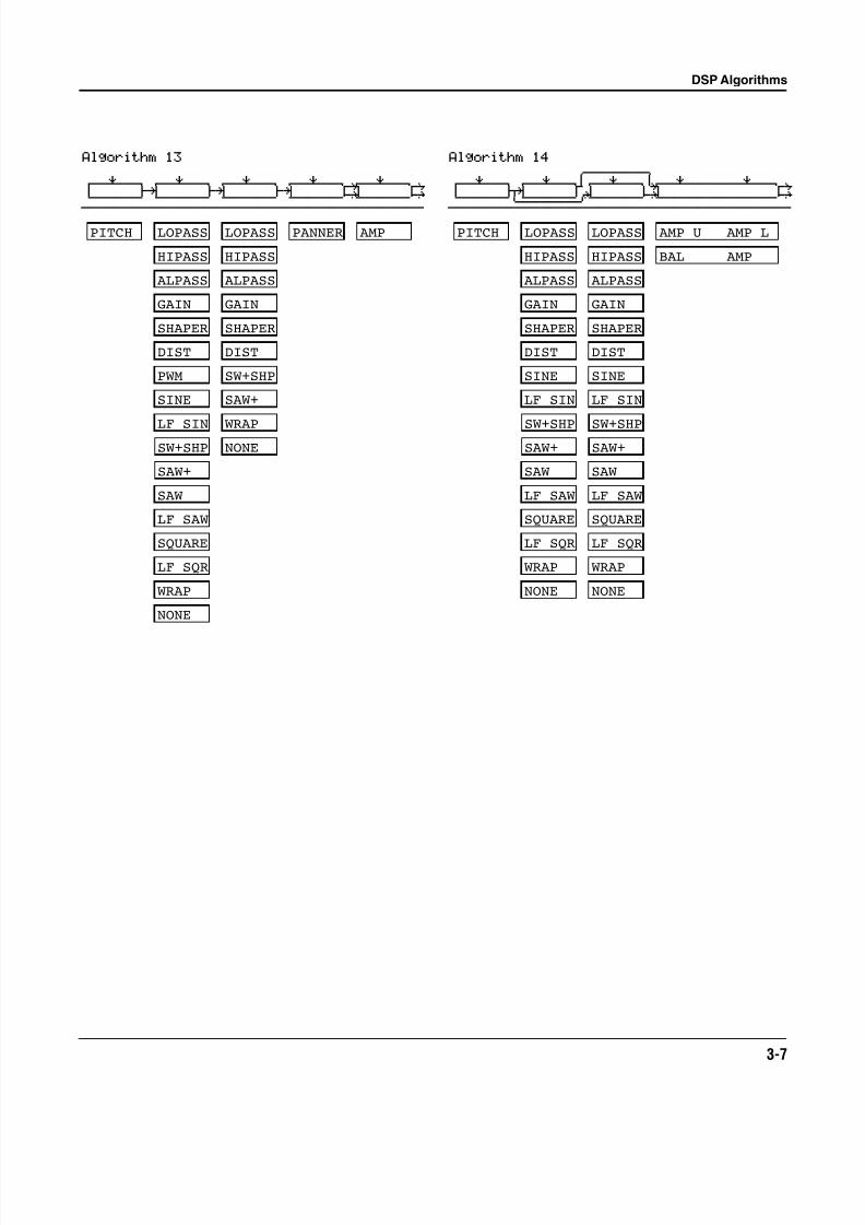
3-7
Algorithm 13
errR®rrterrR®rrterrR®rrterrR®rrtYrrR®rrtyd gk gk gk G; GHcvvvvvvbcvvvvvvbcvvvvvvbcvvvvvvbNvvvvvvbn
PITCH AMPPANNERLOPASS
HIPASS
ALPASS
GAIN
SHAPER
DIST
SW+SHP
SAW+
NONE
SINE
LF SIN
PWM
SAW
LF SAW
SQUARE
LF SQR
WRAP
LOPASS
HIPASS
ALPASS
GAIN
SHAPER
DIST
SW+SHP
SAW+
NONEWRAP
Algorithm 145rrrrrrrr6
errR®rrterrR®rrTerrR®rrt7rrR®rrrrrrR®rrtyd jk u? i; GHcvvvvvvm,......M/vvvvvvbNvvvvvvvvvvvvvvbn
AMP U AMP L
BAL AMP
PITCH LOPASS
HIPASS
ALPASS
GAIN
SHAPER
DIST
SW+SHPSAW+
NONE
SINE
LF SIN
SAW
LF SAW
SQUARE
LF SQR
WRAP
LOPASS
HIPASS
ALPASS
GAIN
SHAPER
DIST
SW+SHPSAW+
NONE
SINE
LF SIN
SAW
LF SAW
SQUARE
LF SQR
WRAP
8/21/2019 MR_K2661
http://slidepdf.com/reader/full/mrk2661 26/499
3-8
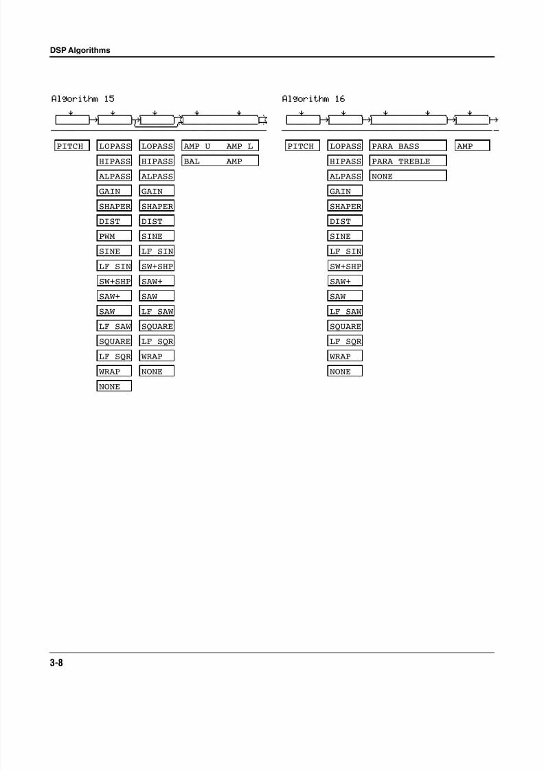
DSP Algorithms
Algorithm 15
errR®rrterrR®rrterrR®rrtYrrR®rrrrrrR®rrtyd gk jk u: GHcvvvvvvbcvvvvvvm,......M/vvvvvvvvvvvvvvbn
PITCH LOPASS
HIPASS
ALPASS
GAIN
SHAPER
DIST
SW+SHP
SAW+
NONE
SINE
LF SIN
PWM
SAW
LF SAW
SQUARE
LF SQR
WRAP
LOPASS
HIPASS
ALPASS
GAIN
SHAPER
DIST
SW+SHPSAW+
NONE
SINE
LF SIN
SAW
LF SAW
SQUARE
LF SQR
WRAP
AMP U AMP L
BAL AMP
Algorithm 16
errR®rrterrR®rrterrR®rrrrrrR®rrterrR®rrt d gk gk gk ghcvvvvvvbcvvvvvvbcvvvvvvvvvvvvvvbcvvvvvvb|
PARA BASS
PARA TREBLE
NONE
PITCH LOPASS
HIPASS
ALPASS
GAIN
SHAPER
DIST
SW+SHPSAW+
NONE
SINE
LF SIN
SAW
LF SAW
SQUARE
LF SQR
WRAP
AMP
8/21/2019 MR_K2661
http://slidepdf.com/reader/full/mrk2661 27/499
DSP Algorithms
3-9
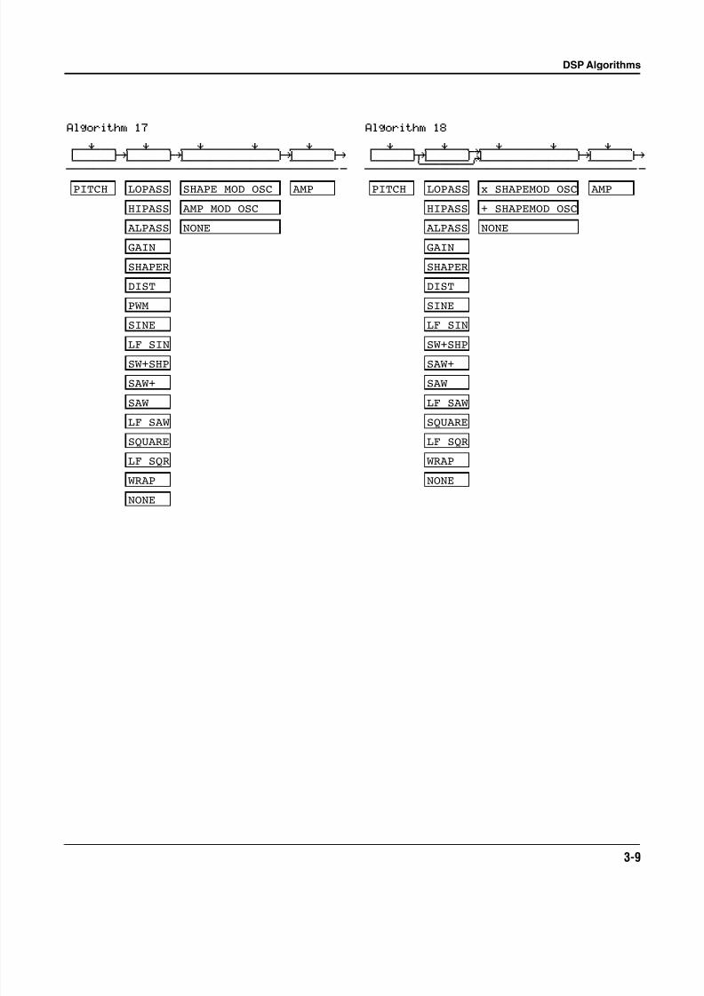
Algorithm 17
errR®rrterrR®rrterrR®rrrrrrR®rrterrR®rrt d gk gk gk ghcvvvvvvbcvvvvvvbcvvvvvvvvvvvvvvbcvvvvvvb|
PITCH AMPLOPASS
HIPASS
ALPASS
GAIN
SHAPER
DIST
SW+SHP
SAW+
NONE
SINE
LF SIN
PWM
SAW
LF SAW
SQUARE
LF SQR
WRAP
AMP MOD OSC
SHAPE MOD OSC
NONE
Algorithm 18
errR®rrterrR®rrtYrrR®rrrrrrR®rrterrR®rrt d jk u: gk ghcvvvvvvm,......M/vvvvvvvvvvvvvvbcvvvvvvb|
PITCH LOPASS
HIPASS
ALPASS
GAIN
SHAPER
DIST
SW+SHPSAW+
NONE
SINE
LF SIN
SAW
LF SAW
SQUARE
LF SQR
WRAP
AMP
NONE
+ SHAPEMOD OSC
x SHAPEMOD OSC
8/21/2019 MR_K2661
http://slidepdf.com/reader/full/mrk2661 28/499
3-10
DSP Algorithms
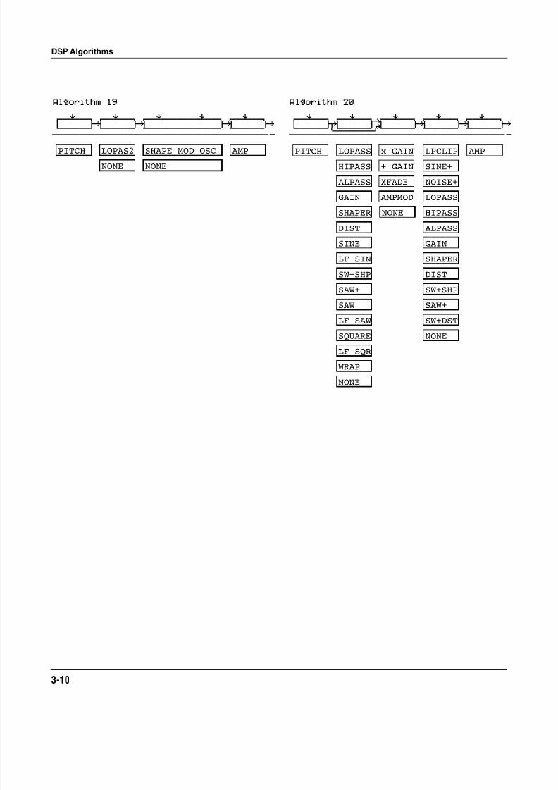
Algorithm 19
errR®rrterrR®rrterrR®rrrrrrR®rrterrR®rrt d gk gk gk ghcvvvvvvbcvvvvvvbcvvvvvvvvvvvvvvbcvvvvvvb|
LOPAS2PITCH AMP
NONE
SHAPE MOD OSC
NONE
Algorithm 20
errR®rrterrR®rrtYrrR®rrterrR®rrterrR®rrt d jk u: gk gk ghcvvvvvvm,......M/vvvvvvbcvvvvvvbcvvvvvvb|
SW+DST
x GAIN
+ GAIN
XFADE
AMPMOD
PITCH LOPASS
HIPASS
ALPASS
GAIN
SHAPER
DIST
SW+SHPSAW+
NONE
SINE
LF SIN
SAW
LF SAW
SQUARE
LF SQR
WRAP
NONE
LOPASS
HIPASS
ALPASS
GAIN
SHAPER
DISTSW+SHP
SAW+
NONE
AMPLPCLIP
SINE+
NOISE+
8/21/2019 MR_K2661
http://slidepdf.com/reader/full/mrk2661 29/499
DSP Algorithms
3-11
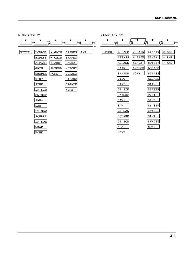
Algorithm 21
errR®rrterrR®rrtYrrR®rrterrR®rrterrR®rrt d jk u: gk gk ghcvvvvvvm,......M/vvvvvvbcvvvvvvbcvvvvvvb|
PITCH AMPLOPASS
HIPASS
ALPASS
GAIN
SHAPER
DIST
SW+SHPSAW+
NONE
BAND2
NOTCH2
LOPAS2
HIPAS2
LPGATESINE
LF SIN
SAW
LF SAW
SQUARE
LF SQR
WRAP
x GAIN
+ GAIN
XFADE
AMPMOD
NONE
NONE
LP2RES
SHAPE2
Algorithm 225rrrrrrrr6
errR®rrterrR®rrTYrrR®rrt7rrR®rrtYrrR®rrt d jk u: JU u: ghcvvvvvvm,......M/vvvvvvm,......M/vvvvvvb|
SW+DST
x AMP
+ AMP
PITCH LOPASS
HIPASS
ALPASS
GAIN
SHAPER
DIST
SW+SHPSAW+
NONE
SINE
LF SIN
SAW
LF SAW
SQUARE
LF SQR
WRAP
x GAIN
+ GAIN
XFADE
AMPMOD
NONE
LOPASS
HIPASS
ALPASS
GAIN
SHAPER
DIST
SW+SHP
SAW+
SINE
LF SIN
NONE
! AMP
LPCLIP
SINE+
NOISE+
8/21/2019 MR_K2661
http://slidepdf.com/reader/full/mrk2661 30/499
3-12
DSP Algorithms
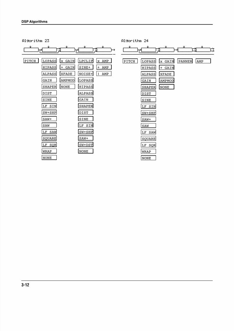
Algorithm 23
errR®rrterrR®rrtYrrR®rrterrR®rrtYrrR®rrt d jk u: jk u: ghcvvvvvvm,......M/vvvvvvm,......M/vvvvvvb|
SW+DST
x AMP
+ AMP
PITCH LOPASS
HIPASS
ALPASS
GAIN
SHAPER
DIST
SW+SHP
SAW+
NONE
SINE
LF SIN
SAW
LF SAW
SQUARE
LF SQR
WRAP
x GAIN
+ GAIN
XFADE
AMPMOD
NONE
LOPASS
HIPASS
ALPASS
GAIN
SHAPER
DIST
SW+SHP
SAW+
SINE
LF SIN
NONE
! AMP
LPCLIP
SINE+
NOISE+
Algorithm 24
errR®rrterrR®rrtYrrR®rrterrR®rrtYrrR®rrtyd jk u: gk G; GHcvvvvvvm,......M/vvvvvvbcvvvvvvbNvvvvvvbn
PANNERPITCH LOPASS
HIPASS
ALPASS
GAIN
SHAPER
DIST
SW+SHP
SAW+
NONE
SINE
LF SIN
SAW
LF SAW
SQUARE
LF SQR
WRAP
x GAIN
+ GAIN
XFADE
AMPMOD
NONE
AMP
8/21/2019 MR_K2661
http://slidepdf.com/reader/full/mrk2661 31/499
DSP Algorithms
3-13
Algorithm 255rrrrrrrr6
errR®rrterrR®rrTYrrR®rrt7rrR®rrrrrrR®rrtyd jk u: i; GHcvvvvvvm,......M/vvvvvvbNvvvvvvvvvvvvvvbn
PITCH AMP U AMP L
BAL AMP
LOPASS
HIPASS
ALPASS
GAIN
SHAPER
DIST
SW+SHPSAW+
NONE
SINE
LF SIN
SAW
LF SAW
SQUARE
LF SQR
WRAP
x GAIN
+ GAIN
XFADE
AMPMOD
NONE
Algorithm 26
errR®rrterrR®rrterrR®rrtYrrR®rrty d ©d gk G; GH||||||||cvvvvvvbcvvvvvvbcvvvvvvbNvvvvvvbn
AMPPANNERSYNC M SYNC S
8/21/2019 MR_K2661
http://slidepdf.com/reader/full/mrk2661 32/499
3-14
DSP Algorithms
Algorithm 27
errR®rrterrR®rrterrR®rrterrR®rrt d ©d gk gk gh
||||||||cvvvvvvbcvvvvvvbcvvvvvvbcvvvvvvb|
SW+DST
AMPSYNC M SYNC S
LOPASS
HIPASS
ALPASS
GAIN
SHAPER
DIST
SW+SHP
SAW+
SINE
LF SIN
NONE
LPCLIP
SINE+
NOISE+
Algorithm 28
errR®rrterrR®rrterrR®rrterrR®rrt d ©d gk gk gh
||||||||cvvvvvvbcvvvvvvbcvvvvvvbcvvvvvvb|
BAND2
NOTCH2
LOPAS2
HIPAS2
LPGATE
AMPSYNC M SYNC S
NONE
LP2RES
SHAPE2
8/21/2019 MR_K2661
http://slidepdf.com/reader/full/mrk2661 33/499
DSP Algorithms
3-15
Algorithm 295rrrrrrrr6
errR®rrterrR®rrTerrR®rrt7rrR®rrt d jd u? i; gh
||||||||cvvvvvvm,......M/vvvvvvbNvvvvvvb|
LOPASS
HIPASS
ALPASS
GAIN
SHAPER
DIST
SW+SHP
SAW+
SW+DST
NONE
x AMP
+ AMP
SINE
LF SIN
SYNC M SYNC S LPCLIP
SINE+
NOISE+ ! AMP
Algorithm 30
errR®rrterrR®rrtYrrR®rrtYrrR®rrt d jd G; u: gh
||||||||cvvvvvvm,......ML......M/vvvvvvb|
SYNC M SYNC S
LOPASS
HIPASS
ALPASS
GAIN
SHAPER
DIST
SW+SHP
SAW+
SW+DST
NONE
SINE
LF SIN
LPCLIP
SINE+
NOISE+
x AMP
+ AMP
! AMP
Algorithm 31
errR®rrterrR®rrtYrrR®rrrrrrR®rrty d jd u: GH||||||||cvvvvvvm,......M/vvvvvvvvvvvvvvbn
AMP U AMP L
BAL AMP
SYNC M SYNC S

8/21/2019 MR_K2661
http://slidepdf.com/reader/full/mrk2661 34/499
3-16
DSP Algorithms
8/21/2019 MR_K2661
http://slidepdf.com/reader/full/mrk2661 35/499
Control Sources
4-1
Chapter 4
Control Sources
Control sources are assigned as values for control source parameters, like Src1 and Src2, DepthControl for Src2, and LFO rate control. Assigning a control source to one of these parameters islike connecting control source outputs to various inputs on early modular synthesizers. You canthink of each control source parameter as the input to a synthesizer module, and the values forthose parameters as the outputs of modules generating control signals.
For the control sources to have an effect, two things have to happen. First, the control sourcemust be assigned as the value for (patched to) a control source parameter like Src1. In otherwords, for a control source parameter to have an effect, it must be programmed to respond to a
particular control message. Second, the control source must generate a signal. The level of thecontrol source’s signal determines how much effect it has on the control source parameter towhich it’s assigned.
In terms of generating signals, there are two types of control sources. The first, which might becalled hardware control sources, require some physical movement to transmit them. The controlsource called MWheel (MIDI 01) is probably the most prominent example of this type of controlsource. When you move your MIDI controller’s Mod Wheel, it sends a Modulation message(MIDI 01), unless you’ve programmed it to send something else. By default, when the K2661receives a MIDI 01 message, it responds by sending a control signal to whatever control source isassigned as the value for the MWhl parameter on the MIDI-mode RECEIVE page. Of course,you can program the MWhl parameter to send any available control source signal in response toMIDI 01 messages.
Some of these hardware control sources have physical controls “hard-wired” to transmit them.That is, there are certain physical controls that always generate these control signals. Every timeyou strike one of your MIDI source’s keys (or pluck a string, or whatever), for example, aNote On message is generated, along with an Attack Velocity message. So any time you strike akey, any control source parameter that has AttVel assigned as its value will be affected by theAttack Velocity message. Similarly, every time you move the physical Pitch Wheel, a PWheelmessage is generated. Whether this affects anything depends on whether you have assigned anycontrol source parameters to respond to the PWheel message (in other words, whether anycontrol source parameter has PWheel assigned as its value).
In the Setup Editor you’ll find several parameters that correspond to the standard physicalcontrollers found on many keyboards. The values you assign for these parameters determinewhich control messages will be transmitted to the K2661 and to its MIDI Out port when youmove the corresponding controls on your MIDI source. If you look at the WHEEL page in theSetup Editor, you’ll see that the parameter called MWhl has a default value of MWheel. You can
interpret this as follows: “Moving the Mod Wheel on my MIDI source sends the MWheel(Modulation, MIDI 01) message to the K2661’s sound engine, and, if the K2661’s LocalKbdChparameter matches my controller’s transmit channel, also sends it to the K2661’s MIDI Outport.”
8/21/2019 MR_K2661
http://slidepdf.com/reader/full/mrk2661 36/499
4-2
Control Sources
If you change the value of the MWhl parameter, the Mod Wheel will no longer send the MWheelmessage, and any control source parameter with MWheel assigned as its value will no longerrespond to movement of the Mod Wheel. All of the control assignment parameters in the SetupEditor can be programmed to send any of the MIDI controller numbers. For example, if youassign Foot (MIDI 04) as the value for the Press parameter, then generating mono pressuremessages from your MIDI source will send a Foot (MIDI 04) message to the K2661’s soundengine, and will affect any control source parameter that has Foot assigned as its value.
The other type of control source is independent of the movement of physical controls. Thesecontrol sources generate their control signals internally, and might be called software controlsources. They either run automatically (like A Clock and RandV1), or they’re programmed togenerate their signals according to parameters of their own (as with the LFOs and FUNs). Thesoftware control sources must have some nonzero value set for one or more of their parameters before they’ll generate control signals.
To summarize, there are two different cases in which you’ll assign control sources. One, thetransmit case, determines what control message will be sent by a particular physical control. Forexample, MWheel is set by default to be transmitted by the Mod Wheel. The other case, thereceive case, determines which control message will activate a particular control source
parameter. For example, if you assign MPress as the value for the Src1 parameter on the PITCHpage in the Program Editor, then that layer’s pitch will be affected whenever an MPress messageis generated by any physical controller.
8/21/2019 MR_K2661
http://slidepdf.com/reader/full/mrk2661 37/499
Control Sources
Control Source Lists
4-3
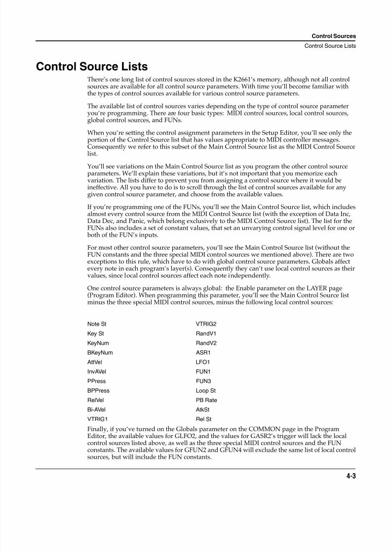
Control Source ListsThere’s one long list of control sources stored in the K2661’s memory, although not all controlsources are available for all control source parameters. With time you’ll become familiar with
the types of control sources available for various control source parameters.The available list of control sources varies depending on the type of control source parameteryou’re programming. There are four basic types: MIDI control sources, local control sources,global control sources, and FUNs.
When you’re setting the control assignment parameters in the Setup Editor, you’ll see only theportion of the Control Source list that has values appropriate to MIDI controller messages.Consequently we refer to this subset of the Main Control Source list as the MIDI Control Sourcelist.
You’ll see variations on the Main Control Source list as you program the other control sourceparameters. We’ll explain these variations, but it’s not important that you memorize eachvariation. The lists differ to prevent you from assigning a control source where it would beineffective. All you have to do is to scroll through the list of control sources available for any
given control source parameter, and choose from the available values.
If you’re programming one of the FUNs, you’ll see the Main Control Source list, which includesalmost every control source from the MIDI Control Source list (with the exception of Data Inc,Data Dec, and Panic, which belong exclusively to the MIDI Control Source list). The list for theFUNs also includes a set of constant values, that set an unvarying control signal level for one or both of the FUN’s inputs.
For most other control source parameters, you’ll see the Main Control Source list (without theFUN constants and the three special MIDI control sources we mentioned above). There are twoexceptions to this rule, which have to do with global control source parameters. Globals affectevery note in each program’s layer(s). Consequently they can’t use local control sources as theirvalues, since local control sources affect each note independently.
One control source parameters is always global: the Enable parameter on the LAYER page(Program Editor). When programming this parameter, you’ll see the Main Control Source listminus the three special MIDI control sources, minus the following local control sources:
Finally, if you’ve turned on the Globals parameter on the COMMON page in the ProgramEditor, the available values for GLFO2, and the values for GASR2’s trigger will lack the localcontrol sources listed above, as well as the three special MIDI control sources and the FUNconstants. The available values for GFUN2 and GFUN4 will exclude the same list of local controlsources, but will include the FUN constants.
Note St VTRIG2
Key St RandV1
KeyNum RandV2
BKeyNum ASR1
AttVel LFO1
InvAVel FUN1
PPress FUN3
BPPress Loop St
RelVel PB Rate
Bi-AVel AtkSt
VTRIG1 Rel St

8/21/2019 MR_K2661
http://slidepdf.com/reader/full/mrk2661 38/499
4-4
Control Sources
Descriptions of Control Sources
Descriptions of Control SourcesThis section is organized into two sets of descriptions: the MIDI Control Source list, and the restof the control sources. The numeral preceding the name of each control source can be entered on
the alphanumeric pad to select the control source directly (press Enter after typing the numeral).Many of the MIDI control sources are assigned as default values for the control assignmentparameters in the Setup Editor. We’ll indicate these assignments as they appear, simply bymentioning that they’re the default control source for a control assignment parameter.
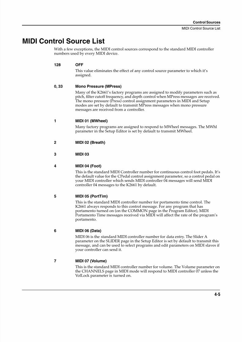
8/21/2019 MR_K2661
http://slidepdf.com/reader/full/mrk2661 39/499
Control Sources
MIDI Control Source List
4-5
MIDI Control Source ListWith a few exceptions, the MIDI control sources correspond to the standard MIDI controllernumbers used by every MIDI device.
128 OFF
This value eliminates the effect of any control source parameter to which it’sassigned.
0, 33 Mono Pressure (MPress)
Many of the K2661’s factory programs are assigned to modify parameters such aspitch, filter cutoff frequency, and depth control when MPress messages are received.The mono pressure (Press) control assignment parameters in MIDI and Setupmodes are set by default to transmit MPress messages when mono pressuremessages are received from a controller.
1 MIDI 01 (MWheel)
Many factory programs are assigned to respond to MWheel messages. The MWhlparameter in the Setup Editor is set by default to transmit MWheel.
2 MIDI 02 (Breath)
3 MIDI 03
4 MIDI 04 (Foot)
This is the standard MIDI Controller number for continuous control foot pedals. It’sthe default value for the CPedal control assignment parameter, so a control pedal on
your MIDI controller which sends MIDI controller 04 messages will send MIDIcontroller 04 messages to the K2661 by default.
5 MIDI 05 (PortTim)
This is the standard MIDI controller number for portamento time control. TheK2661 always responds to this control message. For any program that hasportamento turned on (on the COMMON page in the Program Editor), MIDIPortamento Time messages received via MIDI will affect the rate of the program’sportamento.
6 MIDI 06 (Data)
MIDI 06 is the standard MIDI controller number for data entry. The Slider Aparameter on the SLIDER page in the Setup Editor is set by default to transmit thismessage, and can be used to select programs and edit parameters on MIDI slaves ifyour controller can send it.
7 MIDI 07 (Volume)
This is the standard MIDI controller number for volume. The Volume parameter onthe CHANNELS page in MIDI mode will respond to MIDI controller 07 unless theVolLock parameter is turned on.
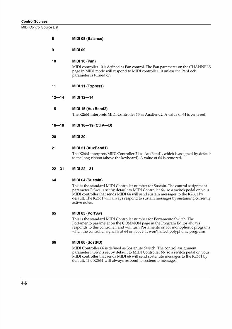
8/21/2019 MR_K2661
http://slidepdf.com/reader/full/mrk2661 40/499
4-6
Control Sources
MIDI Control Source List
8 MIDI 08 (Balance)
9 MIDI 09
10 MIDI 10 (Pan)
MIDI controller 10 is defined as Pan control. The Pan parameter on the CHANNELSpage in MIDI mode will respond to MIDI controller 10 unless the PanLockparameter is turned on.
11 MIDI 11 (Express)
12—14 MIDI 12—14
15 MIDI 15 (AuxBend2)
The K2661 interprets MIDI Controller 15 as AuxBend2. A value of 64 is centered.
16—19 MIDI 16—19 (Ctl A—D)
20 MIDI 20
21 MIDI 21 (AuxBend1)
The K2661 interprets MIDI Controller 21 as AuxBend1, which is assigned by defaultto the long ribbon (above the keyboard). A value of 64 is centered.
22—31 MIDI 22—31
64 MIDI 64 (Sustain)
This is the standard MIDI Controller number for Sustain. The control assignmentparameter FtSw1 is set by default to MIDI Controller 64, so a switch pedal on yourMIDI controller that sends MIDI 64 will send sustain messages to the K2661 bydefault. The K2661 will always respond to sustain messages by sustaining currentlyactive notes.
65 MIDI 65 (PortSw)
This is the standard MIDI Controller number for Portamento Switch. ThePortamento parameter on the COMMON page in the Program Editor alwaysresponds to this controller, and will turn Portamento on for monophonic programs
when the controller signal is at 64 or above. It won’t affect polyphonic programs.
66 MIDI 66 (SostPD)
MIDI Controller 66 is defined as Sostenuto Switch. The control assignmentparameter FtSw2 is set by default to MIDI Controller 66, so a switch pedal on yourMIDI controller that sends MIDI 66 will send sostenuto messages to the K2661 bydefault. The K2661 will always respond to sostenuto messages.
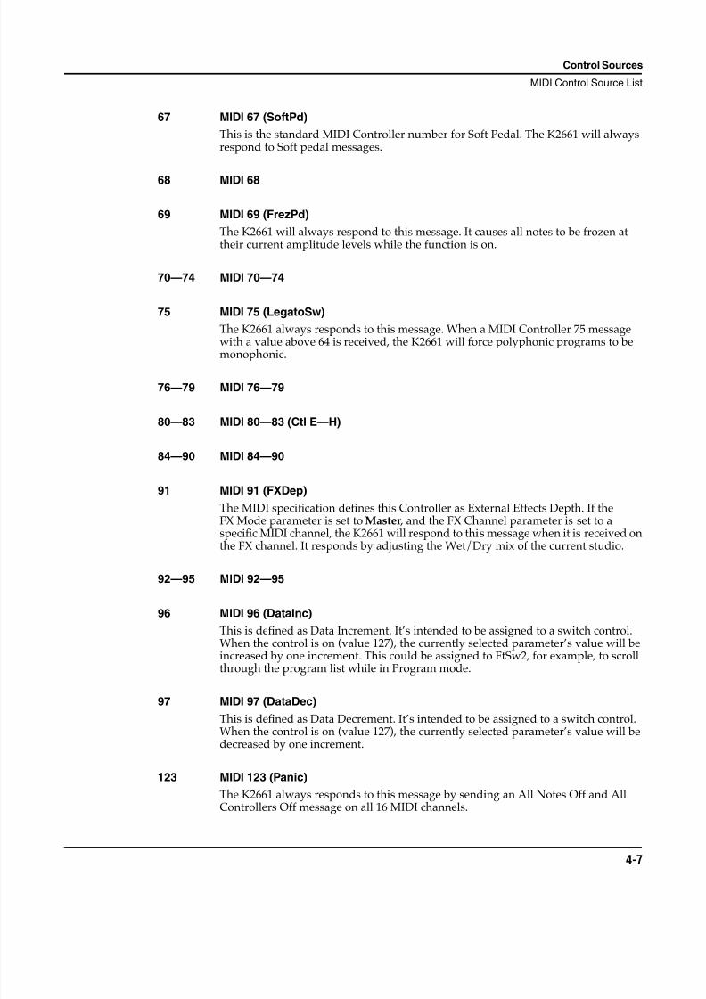
8/21/2019 MR_K2661
http://slidepdf.com/reader/full/mrk2661 41/499
Control Sources
MIDI Control Source List
4-7
67 MIDI 67 (SoftPd)
This is the standard MIDI Controller number for Soft Pedal. The K2661 will alwaysrespond to Soft pedal messages.
68 MIDI 68
69 MIDI 69 (FrezPd)
The K2661 will always respond to this message. It causes all notes to be frozen attheir current amplitude levels while the function is on.
70—74 MIDI 70—74
75 MIDI 75 (LegatoSw)
The K2661 always responds to this message. When a MIDI Controller 75 messagewith a value above 64 is received, the K2661 will force polyphonic programs to bemonophonic.
76—79 MIDI 76—79
80—83 MIDI 80—83 (Ctl E—H)
84—90 MIDI 84—90
91 MIDI 91 (FXDep)
The MIDI specification defines this Controller as External Effects Depth. If the
FX Mode parameter is set to Master , and the FX Channel parameter is set to aspecific MIDI channel, the K2661 will respond to this message when it is received onthe FX channel. It responds by adjusting the Wet/Dry mix of the current studio.
92—95 MIDI 92—95
96 MIDI 96 (DataInc)
This is defined as Data Increment. It’s intended to be assigned to a switch control.When the control is on (value 127), the currently selected parameter’s value will beincreased by one increment. This could be assigned to FtSw2, for example, to scrollthrough the program list while in Program mode.
97 MIDI 97 (DataDec)
This is defined as Data Decrement. It’s intended to be assigned to a switch control.When the control is on (value 127), the currently selected parameter’s value will bedecreased by one increment.
123 MIDI 123 (Panic)
The K2661 always responds to this message by sending an All Notes Off and AllControllers Off message on all 16 MIDI channels.
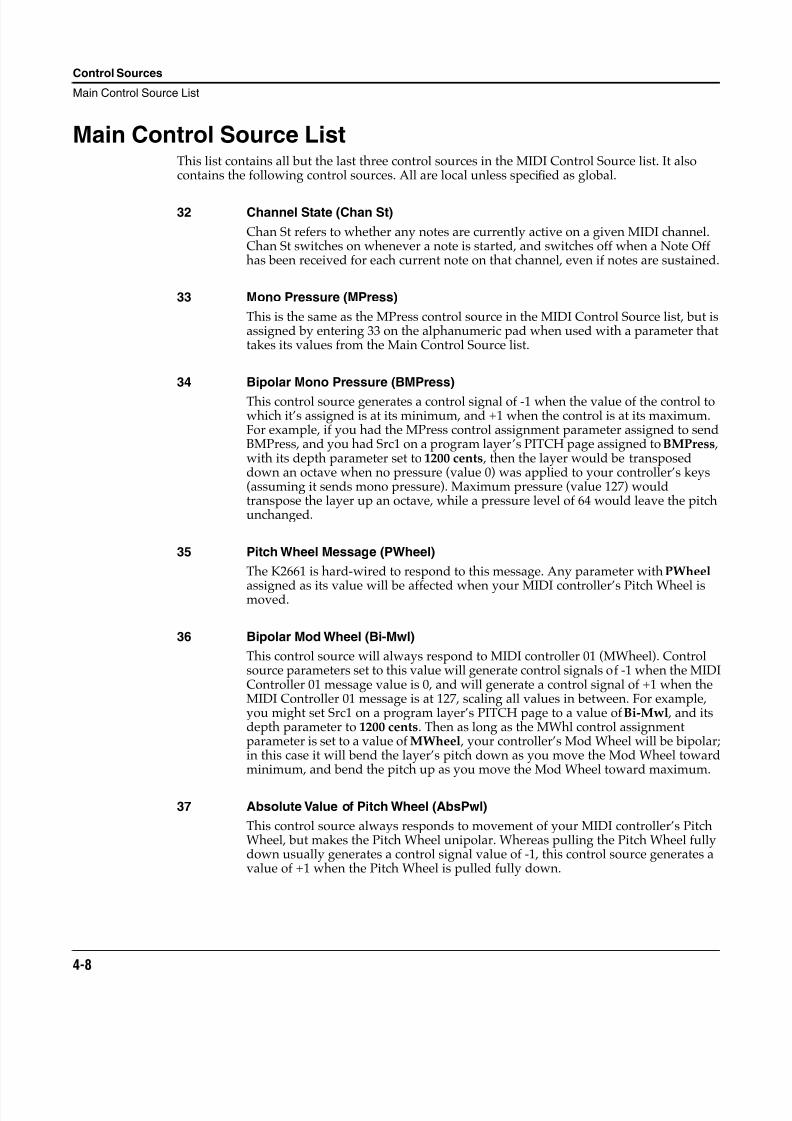
8/21/2019 MR_K2661
http://slidepdf.com/reader/full/mrk2661 42/499
4-8
Control Sources
Main Control Source List
Main Control Source ListThis list contains all but the last three control sources in the MIDI Control Source list. It alsocontains the following control sources. All are local unless specified as global.
32 Channel State (Chan St)
Chan St refers to whether any notes are currently active on a given MIDI channel.Chan St switches on whenever a note is started, and switches off when a Note Offhas been received for each current note on that channel, even if notes are sustained.
33 Mono Pressure (MPress)
This is the same as the MPress control source in the MIDI Control Source list, but isassigned by entering 33 on the alphanumeric pad when used with a parameter thattakes its values from the Main Control Source list.
34 Bipolar Mono Pressure (BMPress)
This control source generates a control signal of -1 when the value of the control towhich it’s assigned is at its minimum, and +1 when the control is at its maximum.For example, if you had the MPress control assignment parameter assigned to sendBMPress, and you had Src1 on a program layer’s PITCH page assigned to BMPress ,with its depth parameter set to 1200 cents , then the layer would be transposeddown an octave when no pressure (value 0) was applied to your controller’s keys(assuming it sends mono pressure). Maximum pressure (value 127) wouldtranspose the layer up an octave, while a pressure level of 64 would leave the pitchunchanged.
35 Pitch Wheel Message (PWheel)
The K2661 is hard-wired to respond to this message. Any parameter with PWheel
assigned as its value will be affected when your MIDI controller’s Pitch Wheel ismoved.
36 Bipolar Mod Wheel (Bi-Mwl)
This control source will always respond to MIDI controller 01 (MWheel). Controlsource parameters set to this value will generate control signals of -1 when the MIDIController 01 message value is 0, and will generate a control signal of +1 when theMIDI Controller 01 message is at 127, scaling all values in between. For example,you might set Src1 on a program layer’s PITCH page to a value of Bi-Mwl , and itsdepth parameter to 1200 cents. Then as long as the MWhl control assignmentparameter is set to a value of MWheel , your controller’s Mod Wheel will be bipolar;in this case it will bend the layer’s pitch down as you move the Mod Wheel towardminimum, and bend the pitch up as you move the Mod Wheel toward maximum.
37 Absolute Value of Pitch Wheel (AbsPwl)
This control source always responds to movement of your MIDI controller’s PitchWheel, but makes the Pitch Wheel unipolar. Whereas pulling the Pitch Wheel fullydown usually generates a control signal value of -1, this control source generates avalue of +1 when the Pitch Wheel is pulled fully down.

8/21/2019 MR_K2661
http://slidepdf.com/reader/full/mrk2661 43/499
Control Sources
Main Control Source List
4-9
38 Global ASR (GASR2)
When the Globals parameter on the COMMON page is turned on, ASR2 becomesglobal, and is labeled GASR2. The functions of ASRs are explained in Chapter 6 ofthe Musician’s Guide. This control source does not appear in the Control Source list
for parameters whose functions are local.
39 Global FUN2 (GFUN2)
When the Globals parameter on the COMMON page is turned on, FUN2 becomesglobal, and is labeled GFUN2. The functions of FUNs are explained in Chapter 17 ofthe Musician’s Guide. This control source does not appear in the Control Source listfor parameters whose functions are local.
40 Global LFO (GLFO2)
When the Globals parameter on the COMMON page is turned on, LFO2 becomesglobal, and is labeled GLFO2. The functions of LFOs are explained in Chapter 6 ofthe Musician’s Guide. This control source does not appear in the Control Source list
for parameters whose functions are local.
41 Global LFO Phase (GLFO2ph)
When the Globals parameter on the COMMON page is turned on, LFO2 becomesglobal, and is labeled GLFO2. The functions of LFOs are explained in the Musician’sGuide. This control source does not appear in the Control Source list for parameterswhose functions are local.
42 Global FUN 4 (GFUN4)
When the Globals parameter on the COMMON page is turned on, FUN 4 becomesglobal, and is labeled GFUN4. This control source does not appear in the ControlSource list for parameters whose functions are local.
43 Volume Control (VolCtl)
This control source will always respond to MIDI Controller 07 messages. Assign thisvalue to a parameter when you want MIDI volume messages to affect theparameter.
44 Pan Control (PanCtl)
This control source always responds to MIDI Controller 10 messages. Assign thisvalue to a parameter when you want MIDI pan messages to affect the parameter.
45 Balance Control (BalCtl)
This control source will always respond to MIDI Controller 08 messages. Assign thisvalue to a parameter when you want MIDI balance messages to affect theparameter.
46 Channel Count (ChanCnt)
This control source keeps track of the total number of active voice channels (howmany notes are playing), and converts the number into a control signal between 0and +1. The control signal’s value is 1 when all 48 voice channels are active, and 0when no voice channels are active.
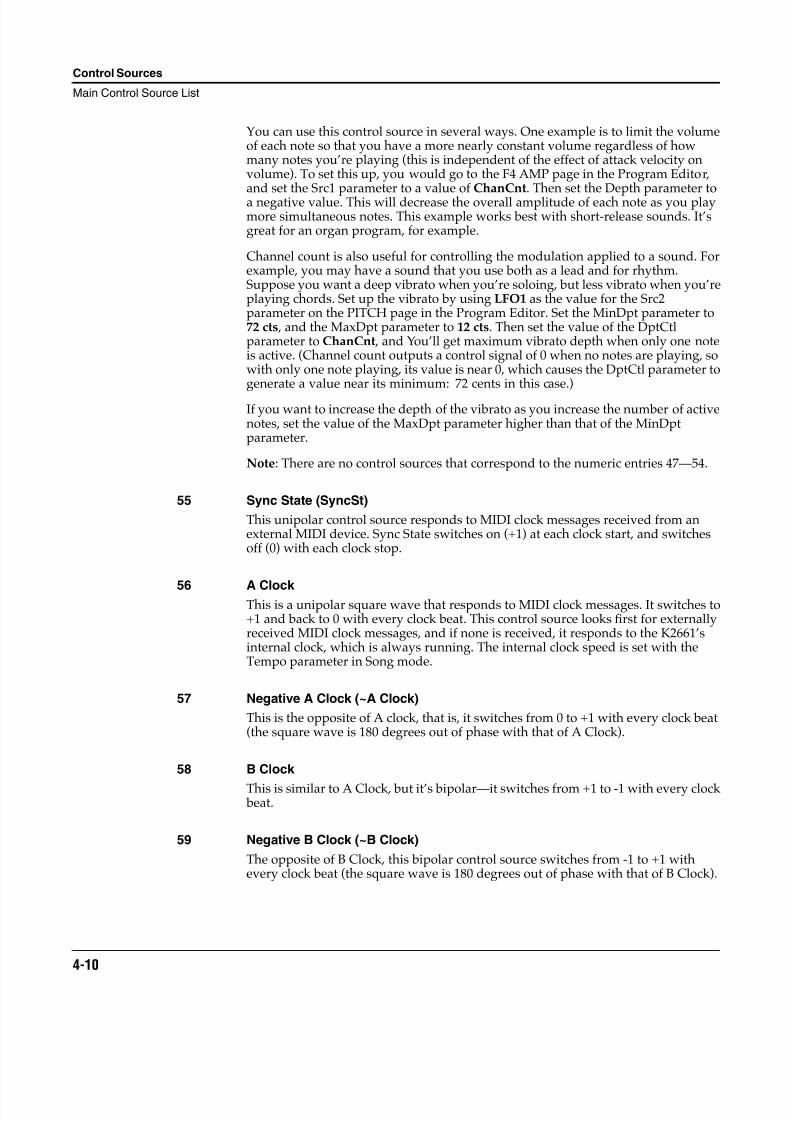
8/21/2019 MR_K2661
http://slidepdf.com/reader/full/mrk2661 44/499
4-10
Control Sources
Main Control Source List
You can use this control source in several ways. One example is to limit the volumeof each note so that you have a more nearly constant volume regardless of howmany notes you’re playing (this is independent of the effect of attack velocity onvolume). To set this up, you would go to the F4 AMP page in the Program Editor,and set the Src1 parameter to a value of ChanCnt. Then set the Depth parameter toa negative value. This will decrease the overall amplitude of each note as you playmore simultaneous notes. This example works best with short-release sounds. It’sgreat for an organ program, for example.
Channel count is also useful for controlling the modulation applied to a sound. Forexample, you may have a sound that you use both as a lead and for rhythm.Suppose you want a deep vibrato when you’re soloing, but less vibrato when you’replaying chords. Set up the vibrato by using LFO1 as the value for the Src2parameter on the PITCH page in the Program Editor. Set the MinDpt parameter to72 cts , and the MaxDpt parameter to 12 cts. Then set the value of the DptCtlparameter to ChanCnt , and You’ll get maximum vibrato depth when only one noteis active. (Channel count outputs a control signal of 0 when no notes are playing, sowith only one note playing, its value is near 0, which causes the DptCtl parameter togenerate a value near its minimum: 72 cents in this case.)
If you want to increase the depth of the vibrato as you increase the number of activenotes, set the value of the MaxDpt parameter higher than that of the MinDptparameter.
Note: There are no control sources that correspond to the numeric entries 47—54.
55 Sync State (SyncSt)
This unipolar control source responds to MIDI clock messages received from anexternal MIDI device. Sync State switches on (+1) at each clock start, and switchesoff (0) with each clock stop.
56 A Clock This is a unipolar square wave that responds to MIDI clock messages. It switches to+1 and back to 0 with every clock beat. This control source looks first for externallyreceived MIDI clock messages, and if none is received, it responds to the K2661’sinternal clock, which is always running. The internal clock speed is set with theTempo parameter in Song mode.
57 Negative A Clock (~A Clock)
This is the opposite of A clock, that is, it switches from 0 to +1 with every clock beat(the square wave is 180 degrees out of phase with that of A Clock).
58 B Clock
This is similar to A Clock, but it’s bipolar—it switches from +1 to -1 with every clock beat.
59 Negative B Clock (~B Clock)
The opposite of B Clock, this bipolar control source switches from -1 to +1 withevery clock beat (the square wave is 180 degrees out of phase with that of B Clock).
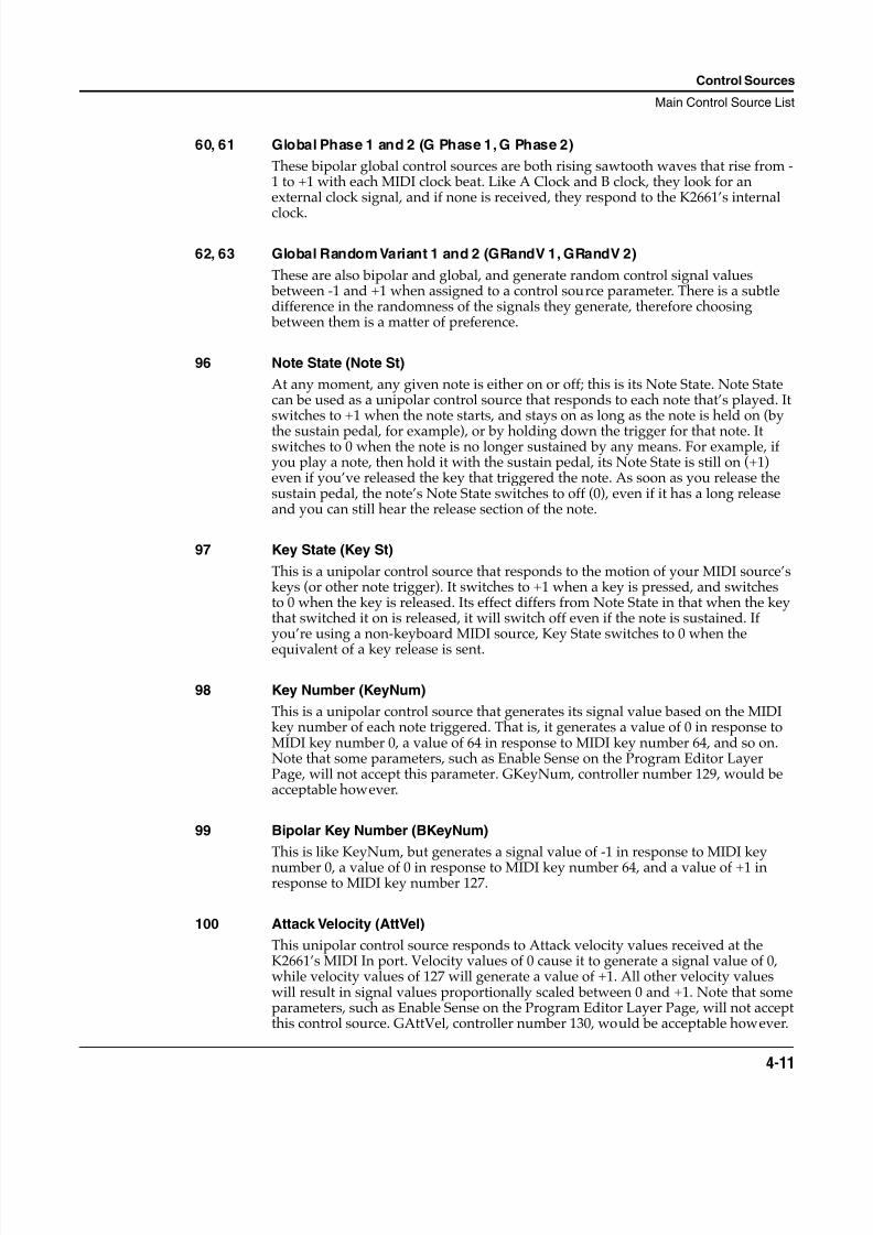
8/21/2019 MR_K2661
http://slidepdf.com/reader/full/mrk2661 45/499
Control Sources
Main Control Source List
4-11
60, 61 Global Phase 1 and 2 (G Phase 1, G Phase 2)
These bipolar global control sources are both rising sawtooth waves that rise from -1 to +1 with each MIDI clock beat. Like A Clock and B clock, they look for anexternal clock signal, and if none is received, they respond to the K2661’s internal
clock.
62, 63 Global Random Variant 1 and 2 (GRandV 1, GRandV 2)
These are also bipolar and global, and generate random control signal values between -1 and +1 when assigned to a control source parameter. There is a subtledifference in the randomness of the signals they generate, therefore choosing between them is a matter of preference.
96 Note State (Note St)
At any moment, any given note is either on or off; this is its Note State. Note Statecan be used as a unipolar control source that responds to each note that’s played. Itswitches to +1 when the note starts, and stays on as long as the note is held on (by
the sustain pedal, for example), or by holding down the trigger for that note. Itswitches to 0 when the note is no longer sustained by any means. For example, ifyou play a note, then hold it with the sustain pedal, its Note State is still on (+1)even if you’ve released the key that triggered the note. As soon as you release thesustain pedal, the note’s Note State switches to off (0), even if it has a long releaseand you can still hear the release section of the note.
97 Key State (Key St)
This is a unipolar control source that responds to the motion of your MIDI source’skeys (or other note trigger). It switches to +1 when a key is pressed, and switchesto 0 when the key is released. Its effect differs from Note State in that when the keythat switched it on is released, it will switch off even if the note is sustained. Ifyou’re using a non-keyboard MIDI source, Key State switches to 0 when the
equivalent of a key release is sent.
98 Key Number (KeyNum)
This is a unipolar control source that generates its signal value based on the MIDIkey number of each note triggered. That is, it generates a value of 0 in response toMIDI key number 0, a value of 64 in response to MIDI key number 64, and so on.Note that some parameters, such as Enable Sense on the Program Editor LayerPage, will not accept this parameter. GKeyNum, controller number 129, would beacceptable however.
99 Bipolar Key Number (BKeyNum)
This is like KeyNum, but generates a signal value of -1 in response to MIDI key
number 0, a value of 0 in response to MIDI key number 64, and a value of +1 inresponse to MIDI key number 127.
100 Attack Velocity (AttVel)
This unipolar control source responds to Attack velocity values received at theK2661’s MIDI In port. Velocity values of 0 cause it to generate a signal value of 0,while velocity values of 127 will generate a value of +1. All other velocity valueswill result in signal values proportionally scaled between 0 and +1. Note that someparameters, such as Enable Sense on the Program Editor Layer Page, will not acceptthis control source. GAttVel, controller number 130, would be acceptable however.
8/21/2019 MR_K2661
http://slidepdf.com/reader/full/mrk2661 46/499
4-12
Control Sources
Main Control Source List
101 Inverse Attack Velocity (InvAttVel)
This is the opposite of AttVel, generating a signal value of 0 in response to attackvelocity values of 127.
102 Polyphonic Pressure (PPress)
This unipolar control source responds to poly pressure (aftertouch) messagesreceived via MIDI. It generates a signal value scaled from 0 to +1 based on the polypressure value range of 0—127.
103 Bipolar Polyphonic Pressure (BPPress)
This is like PPress, but scales its signal value from -1 to +1.
104 Release Velocity (RelVel)
Also unipolar, this control source scales its signal value from 0 to +1 in response torelease velocity values from 0—127.
105 Bipolar Attack Velocity (Bi-AVel)
This is similar to AttVel, but scales its signal values from -1 to +1.
106, 107 Velocity Triggers 1 and 2 (VTRIG1, VTRIG2)
These unipolar control sources are switch controls, that is, they generate signalvalues of either 0 or +1. These must be programmed in order to have an effect; theirprogramming parameters are found on the VTRIG page in the Program Editor.When a VTRIG’s Sense parameter is set to normal, it switches to +1 when a noteplays at a dynamic level exceeding the dynamic level set for its Level parameter. SeeChapter 6 of the Musician’s Guide for more information.
108, 109 Random Variants 1 and 2 (RandV1, RandV2)
These are similar to GRandV1 and GRandV2, but are local, so will affect eachcontrol source parameter independently.
110, 111 ASR1, ASR2
These are programmable envelopes with three segments, Attack, Sustain, andRelease. Their control source signals are unipolar. See Chapter 6 of the Musician’sGuide for a thorough explanation.
112, 113 FUN1, FUN2
These generate their control source signals by combining the control signal values
of two programmable inputs, and performing a mathematical function on theresult. Their control signals can be unipolar or bipolar, depending on the controlsources assigned as their inputs. See Chapter 6 of the Musician’s Guide. FUN2 becomes global (GFUN2) when the Globals parameter on the COMMON page inthe Program Editor is set to On.
114 LFO1
LFO1 can be unipolar or bipolar depending on the value set for the Shapeparameter on its programming page. See Chapter 6 of the Musician’s Guide.
8/21/2019 MR_K2661
http://slidepdf.com/reader/full/mrk2661 47/499
Control Sources
Main Control Source List
4-13
115 LFO1 Phase (LFO1ph)
This bipolar control source generates it signal based on the cycle of LFO1. When thephase of LFO1 is 0 degrees, the signal value of LFO1ph is 0. When the phase ofLFO1 is 90 degrees, the signal value of LFO1ph is 1. When the phase of LFO1 is 180
degrees, the signal value of LFO1ph is 0. When the phase of LFO1 is 270 degrees, thesignal value of LFO1ph is -1.
116 LFO2
This functions exactly the same as LFO1, when the Globals parameter is set to Off (on the COMMON page in the Program Editor). When the Globals parameter is setto On , LFO2 becomes global (GLFO2).
117 LFO2 Phase (LFO2ph)
This functions exactly the same as LFO1ph, responding to the cycle of LFO2.
118, 119 FUN3, FUN4These function exactly the same as FUNs 1 and 2, when the Globals parameter is setto Off (on the COMMON page in the Program Editor). When the Globals parameteris set to On , FUN4 becomes global (GFUN4).
120 Amplitude Envelope (AMPENV)
This programmable unipolar control source lets you vary the effect of a controlsource parameter over time. See Chapter 6 of the Musician’s Guide.
121, 122 Envelopes 2 and 3 (ENV2, ENV3)
These are programmed in the same way as AMPENV, but they can be bipolar.
123 Loop State (Loop St)
This unipolar control source switches to +1 when the currently playing samplereaches its LoopStart point. If you’ve programmed a sound with a User amplitudeenvelope, Loop St will always be on (+1) for that sound. See Chapter 14 of theMusician’s Guide for more about sample loops.
124 Sample Playback Rate (PB Rate)
The signal value of this bipolar control source is determined by the sample playbackrate of each note. The playback rate is a function of the amount of transpositionapplied to a sample root to play it at the proper pitch for each note. If you trigger anote where a sample root is assigned, the PB Rate signal value for that note is 0. Ifthe note is above the sample root, the sample is transposed upward, and its
playback rate is higher than that of the sample root. Consequently the PB Ratesignal value for that note will be positive. If the note is below the sample root, thePB Rate signal value will be negative.
125 Attack State (Atk State)
This unipolar control source switches to +1 and back to 0 very quickly with eachnote start.
8/21/2019 MR_K2661
http://slidepdf.com/reader/full/mrk2661 48/499
4-14
Control Sources
Main Control Source List
126 Release State (Rel State)
This unipolar control source switches to +1 when a note is released, and stays onuntil the note has completed its release (faded to silence), then it switches to 0. Itwill stay on if a note is sustained, even if its trigger (key, string, whatever) is
released.
127 ON
This generates a constant control signal value of +1.
128 -ON
This generates a constant control signal value of -1 (the numeric entry 128 selects avalue of OFF in the MIDI Control Source list).
129 GKeyNum
Uses the key number (global) to modify whatever it is patched into. Higher notes
will have a very different effect than will lower notes. Users can use this new Sourceto control any K2661 parameters, or to scale amplitude or pitch.
130 GAttVel
This is updated every time you strike another key (kind of a multi- trigger function).
In addition to enabling (triggering) layers from any controller (works like an on/offswitch), you can set the assigned controller’s threshold (value, or range of valuesfrom 0-127), thus defining the controller’s active range where it will enable thelayer.
For example, you could create a 32-layer nylon guitar in which each layer isassigned to a different VAST algorithm and each layer is enabled by discrete narrow
velocity ranges. This would produce 32 different sounding layers with 32 crossswitch points emulating a picked guitar where no two attacks are exactly alike. Ifthe layers' velocity ranges were very close together yet not overlapping, you couldcreate very subtle nonrepeating changes. This kind of power usually eludes mostsample playback devices, as this technique uses only one layer of polyphony, due tocross switching versus cross fading.
131, 132 GHiKey, GLoKey
These control sources work the same as GKeyNum except that they track thehighest key currently held and the lowest key currently held respectively. By usingone of these as the only source for pitch tracking, you can create monophonic-likelayers within a polyphonic program.
8/21/2019 MR_K2661
http://slidepdf.com/reader/full/mrk2661 49/499
Control Sources
Constant Control Sources
4-15
Constant Control SourcesThe remaining control sources are constants, which appear only when you’re assigning controlsources as inputs for the FUNs. Assigning one of these values fixes the input’s control signal
value at a steady level.
Note: There are no control sources that correspond to numeric entries 252—254.
Assigned
ValueCorresponding Constant
Assigned
ValueCorresponding Constant
133 -0.99 201 0.09
134 -0.98 202 0.10
135 -0.97 203 0.12
136-140 -0.96 to -0.92 204 0.14
141 -0.91 205 0.16
142 -0.90 206-210 0.18 to 0.26
143-145 -0.88 to -0.84 211-215 0.28 to 0.36
146-150 -0.82 to -0.74 216-220 0.38 to 0.46
151-155 -0.72 to -0.64 221-225 0.48 to 0.56
156-160 -0.62 to -0.54 226-230 0.58 to 0.66
161-165 -0.52 to -0.44 231-235 0.68 to 0.76
166-170 -0.42 to -0.34 236-240 0.78 to 0.86
171-175 -0.32 to -0.24 241 0.88
176-180 -0.22 to -0.14 242 0.90
181 -0.12 243 0.91
182 -0.10 244 0.92
183 -0.09 245 0.93
184 -0.08 246-250 0.94 to 0.98
185 -0.07 251 0.99
186-190 -0.06 to -0.02 256 OFF
191 -0.01
192 0.00
193 0.01
194 0.02
195 0.03
196-200 0.04 to 0.08
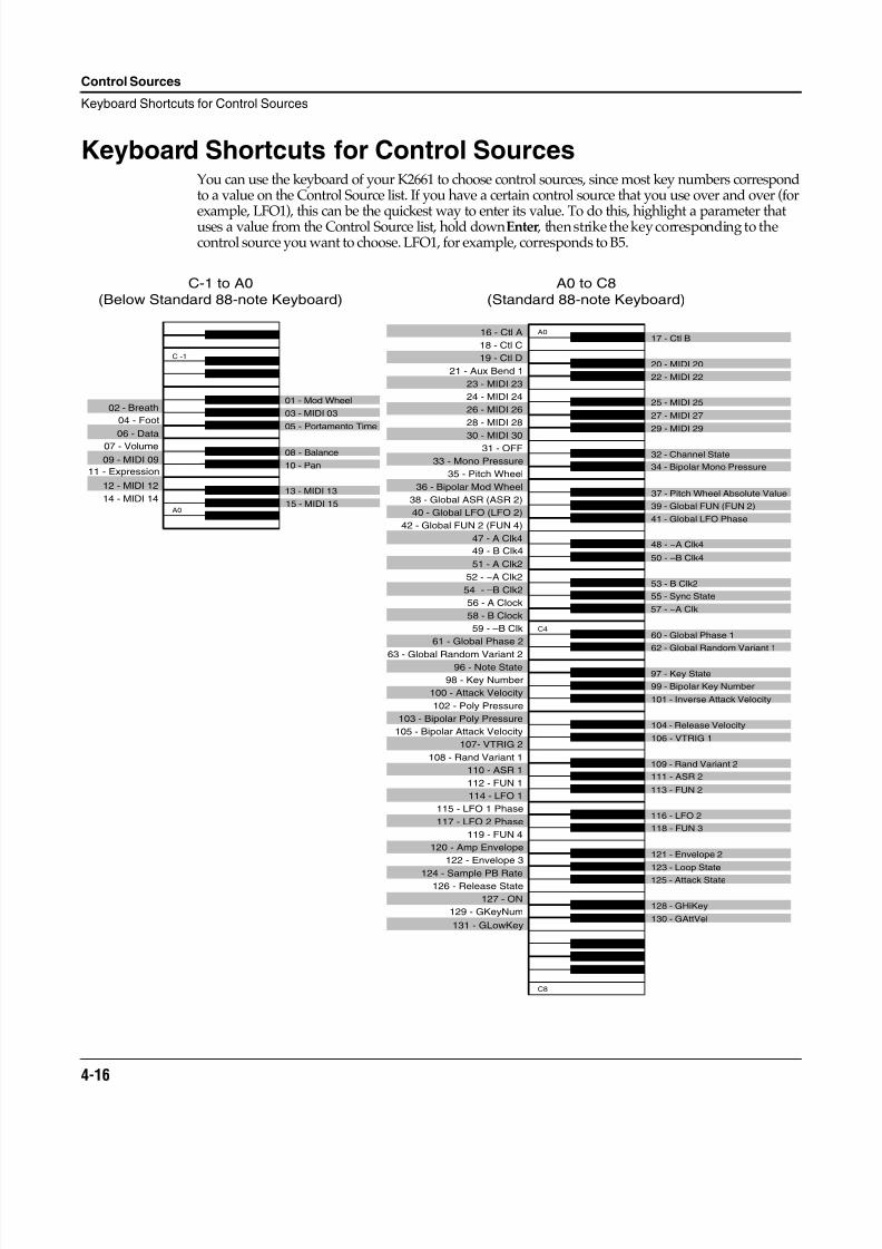
8/21/2019 MR_K2661
http://slidepdf.com/reader/full/mrk2661 50/499
4-16
Control Sources
Keyboard Shortcuts for Control Sources
Keyboard Shortcuts for Control SourcesYou can use the keyboard of your K2661 to choose control sources, since most key numbers correspondto a value on the Control Source list. If you have a certain control source that you use over and over (for
example, LFO1), this can be the quickest way to enter its value. To do this, highlight a parameter thatuses a value from the Control Source list, hold down Enter , then strike the key corresponding to thecontrol source you want to choose. LFO1, for example, corresponds to B5.
63 - Global Random Variant 2
15 - MIDI 1514 - MIDI 14
12 - MIDI 12
10 - Pan
08 - Balance07 - Volume
03 - MIDI 0302 - Breath
16 - Ctl A17 - Ctl B
18 - Ctl C
19 - Ctl D20 - MIDI 20
21 - Aux Bend 122 - MIDI 22
23 - MIDI 23
24 - MIDI 2425 - MIDI 25
26 - MIDI 2627 - MIDI 27
28 - MIDI 2829 - MIDI 29
30 - MIDI 3031 - OFF
32 - Channel State33 - Mono Pressure
34 - Bipolar Mono Pressure35 - Pitch Wheel
36 - Bipolar Mod Wheel
38 - Global ASR (ASR 2)39 - Global FUN (FUN 2)
40 - Global LFO (LFO 2)41 - Global LFO Phase
42 - Global FUN 2 (FUN 4)
47 - A Clk448 - ~A Clk4
49 - B Clk450 - –B Clk4
51 - A Clk2
52 - ~A Clk253 - B Clk2
54 - –B Clk255 - Sync State
56 - A Clock57 - ~A Clk
58 - B Clock
59 - –B Clk60 - Global Phase 1
61 - Global Phase 262 - Global Random Variant 1
96 - Note State97 - Key State
98 - Key Number99 - Bipolar Key Number
100 - Attack Velocity101 - Inverse Attack Velocity
102 - Poly Pressure
103 - Bipolar Poly Pressure104 - Release Velocity
105 - Bipolar Attack Velocity106 - VTRIG 1
107- VTRIG 2
108 - Rand Variant 1109 - Rand Variant 2
110 - ASR 1111 - ASR 2
112 - FUN 1113 - FUN 2
114 - LFO 1
115 - LFO 1 Phase116 - LFO 2
117 - LFO 2 Phase118 - FUN 3
119 - FUN 4
120 - Amp Envelope121 - Envelope 2
122 - Envelope 3123 - Loop State
124 - Sample PB Rate 125 - Attack State126 - Release State
127 - ON128 - GHiKey
129 - GKeyNum130 - GAttVel
131 - GLowKey
A0
C4
04 - Foot
06 - Data
09 - MIDI 09
11 - Expression
13 - MIDI 13
C -1
A0
C-1 to A0
(Below Standard 88-note Keyboard)
A0 to C8
(Standard 88-note Keyboard)
37 - Pitch Wheel Absolute Value
05 - Portamento Time
01 - Mod Wheel
C8
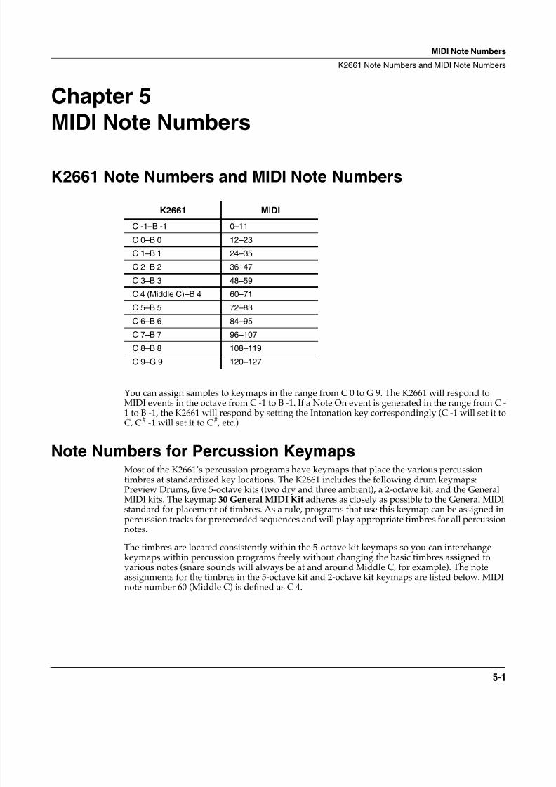
8/21/2019 MR_K2661
http://slidepdf.com/reader/full/mrk2661 51/499
MIDI Note Numbers
K2661 Note Numbers and MIDI Note Numbers
5-1
Chapter 5
MIDI Note Numbers
K2661 Note Numbers and MIDI Note Numbers
You can assign samples to keymaps in the range from C 0 to G 9. The K2661 will respond toMIDI events in the octave from C -1 to B -1. If a Note On event is generated in the range from C -
1 to B -1, the K2661 will respond by setting the Intonation key correspondingly (C -1 will set it toC, C# -1 will set it to C# , etc.)
Note Numbers for Percussion KeymapsMost of the K2661’s percussion programs have keymaps that place the various percussiontimbres at standardized key locations. The K2661 includes the following drum keymaps:Preview Drums, five 5-octave kits (two dry and three ambient), a 2-octave kit, and the GeneralMIDI kits. The keymap 30 General MIDI Kit adheres as closely as possible to the General MIDIstandard for placement of timbres. As a rule, programs that use this keymap can be assigned inpercussion tracks for prerecorded sequences and will play appropriate timbres for all percussionnotes.
The timbres are located consistently within the 5-octave kit keymaps so you can interchangekeymaps within percussion programs freely without changing the basic timbres assigned tovarious notes (snare sounds will always be at and around Middle C, for example). The noteassignments for the timbres in the 5-octave kit and 2-octave kit keymaps are listed below. MIDInote number 60 (Middle C) is defined as C 4.
K2661 MIDI
C -1–B -1 0–11
C 0–B 0 12–23
C 1–B 1 24–35
C 2–B 2 36–47
C 3–B 3 48–59
C 4 (Middle C)–B 4 60–71
C 5–B 5 72–83
C 6–B 6 84–95
C 7–B 7 96–107
C 8–B 8 108–119
C 9–G 9 120–127
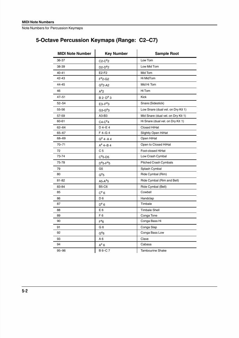
8/21/2019 MR_K2661
http://slidepdf.com/reader/full/mrk2661 52/499
5-2
MIDI Note Numbers
Note Numbers for Percussion Keymaps
5-Octave Percussion Keymaps (Range: C2–C7)
MIDI Note Number Key Number Sample Root
36-37 C2-C#2 Low Tom
38-39 D2-D#2 Low Mid Tom
40-41 E2-F2 Mid Tom
42-43 F#2-G2 Hi MidTom
44-45 G#2-A2 Mid Hi Tom
46 A#2 Hi Tom
47–51 B 2–D# 3 Kick
52–54 E3–F#3 Snare (Sidestick)
55-56 G3-G#3 Low Snare (dual vel. on Dry Kit 1)
57-59 A3-B3 Mid Snare (dual vel. on Dry Kit 1)
60-61 C4-C#4 Hi Snare (dual vel. on Dry Kit 1)
62–64 D 4–E 4 Closed HiHat
65–67 F 4–G 4 Slightly Open HiHat
68–69 G# 4–A 4 Open HiHat
70–71 A# 4–B 4 Open to Closed HiHat
72 C 5 Foot-closed HiHat
73-74 C#5-D5 Low Crash Cymbal
75-78 D#5-F#5 Pitched Crash Cymbals
79 G5 Splash Cymbal
80 G#5 Ride Cymbal (Rim)
81-82 A5-A#5 Ride Cymbal (Rim and Bell)
83-84 B5-C6 Ride Cymbal (Bell)
85 C# 6 Cowbell
86 D 6 Handclap
87 D# 6 Timbale
88 E 6 Timbale Shell
89 F 6 Conga Tone
90 F#6 Conga Bass Hi
91 G 6 Conga Slap
92 G#6 Conga Bass Low
93 A 6 Clave
94 A# 6 Cabasa
95–96 B 6–C 7 Tambourine Shake
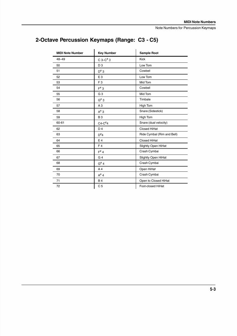
8/21/2019 MR_K2661
http://slidepdf.com/reader/full/mrk2661 53/499
MIDI Note Numbers
Note Numbers for Percussion Keymaps
5-3
2-Octave Percussion Keymaps (Range: C3 - C5)
MIDI Note Number Key Number Sample Root
48–49 C 3–C# 3 Kick
50 D 3 Low Tom
51 D# 3 Cowbell
52 E 3 Low Tom
53 F 3 Mid Tom
54 F# 3 Cowbell
55 G 3 Mid Tom
56 G# 3 Timbale
57 A 3 High Tom
58 A# 3 Snare (Sidestick)
59 B 3 High Tom60-61 C4-C#4 Snare (dual velocity)
62 D 4 Closed HiHat
63 D#4 Ride Cymbal (Rim and Bell)
64 E 4 Closed HiHat
65 F 4 Slightly Open HiHat
66 F# 4 Crash Cymbal
67 G 4 Slightly Open HiHat
68 G# 4 Crash Cymbal
69 A 4 Open HiHat
70A
#
4Crash Cymbal
71 B 4 Open to Closed HiHat
72 C 5 Foot-closed HiHat

8/21/2019 MR_K2661
http://slidepdf.com/reader/full/mrk2661 54/499
5-4
MIDI Note Numbers
Note Numbers for Percussion Keymaps
8/21/2019 MR_K2661
http://slidepdf.com/reader/full/mrk2661 55/499
MIDI, SCSI, and Sample Dumps
SCSI Guidelines
6-1
Chapter 6
MIDI, SCSI, and Sample Dumps
SCSI GuidelinesThe following sections contain information on using SCSI with the K2661, as well as speci ficsections dealing with the Mac and the K2661.
Disk Size RestrictionsThe K2661 can address up to 8 Gigabytes (8 G) of hard-disk space, in 2-G partitions. This is truefor any hard disk formatted with the DOS-compatible FAT-16 format. Hard disks larger than 8 Gcan be formatted to make 8 G (in four partitions) accessible to the K2661. If you attach a formatted
disk larger than 8 gigabytes, the K2661 may not be able to work with it; you could reformat thedisk, but this—of course—would erase the disk entirely.
Configuring a SCSI ChainHere are some basic guidelines to follow when configuring a SCSI chain. For additionalinformation, refer to:
http://www.kurzweilmusicsystems.com/html/scsi_help.html
http://www.kurzweilmusicsystems.com/html/drive_compatibility_info.html
1. According to the SCSI Specification, the maximum SCSI cable length is 6 meters(19.69 feet). You should limit the total length of all SCSI cables connecting external SCSIdevices with Kurzweil products to 17 feet (5.2 meters). To calculate the total SCSI cablelength, add the lengths of all SCSI cables, plus eight inches for every external SCSI deviceconnected. No single cable length in the chain should exceed eight feet.
2. The first and last devices in the chain must be terminated. The K2661 is peramanentlyterminated, so it will always act as an end device on the SCSI chain.
Poor termination is a common cause of SCSI problems. Having more than two terminatorson the bus will overload the bus drivers, but this should not cause permanent damage tothe hardware. Poor termination can corrupt the data on your disk, however, as can badSCSI cables.
A note about active termination: The K2661 uses active termination of the SCSI bus.Active termination has some benefits over traditional passive termination. Some peopleview active termination as a cure for all SCSI problems, but this isn’t true. Activeterminators are appropriate at the end of a SCSI chain. All APS SR2000-series externaldrives use internal active termination that can be switched on or off.
3. Each device in the chain (including internal hard drives) must have its own uniqueSCSI ID. The default K2661 ID is 6. Macintoshes® use 7 and 0.
4. Use only true SCSI cables: high quality, twisted pair, shielded SCSI cable. Do not useRS432 or other nonSCSI cables.
The majority of SCSI cables we’ve tested were poorly made and could damage datatransferred to and from the disk. Nearly all the SCSI data problems Young Chang’s
8/21/2019 MR_K2661
http://slidepdf.com/reader/full/mrk2661 56/499
6-2
MIDI, SCSI, and Sample Dumps
SCSI Guidelines
engineering department has encountered have been due to bad cables that didn’t twistpairs of wires properly. Correctly made SCSI cables have one ground wire for every signalwire and twist them together in signal/ground pairs. Cables made by APS Technologies(http://www.apstech.com, 1-800-395-5871) are very good and are highly recommended.Young Chang manufactures 1 and 2 meter 25-25 SCSI cables, that we can also recommend.Good cables are essential to reliable data transfers to and from the disk drive.
5. You should buy all SCSI cables from a single source to avoid impedance mismatch between cables.
6. Theoretically all eight SCSI IDs can be used. However, feedback from users has shown usthat many people have problems with more than five or six devices in a chain. If you haveseven or eight devices and are having problems, your best bet is to make sure you havefollowed all of the previous information, especially with respect to cables.
7. Connect all SCSI cables before turning on the power on any equipment connected by SCSIcables. Plugging or unplugging SCSI cables while devices are powered on can causedamage to your devices or instrument.
8. When using a Macintosh, power up the K2661 and other devices first.
9. The K2661 file format is a proprietary format; no other device will be able to read or writea Kurzweil file.
10. The K2661 can read from and write to the first partition on a DOS-formatted disk.
11. As long as the SCSI bus is properly terminated there is no way you can damage yourhardware simply by operating it. There are a few hazards you should be aware of,however:
The only damage that usually occurs to SCSI hardware comes from static electricitydischarging to SCSI connector pins when the cables are disconnected. The silver colored
shell of the SCSI connector on the end of the cable is connected to ground and is safe totouch, but the brass colored pins inside eventually lead to the SCSI interface chip and arevulnerable. You should discharge static from your body before touching SCSI connectors, by touching the 1/4-inch jacks on the rear of the K2661 or another grounded metal object.Any devices connected to the SCSI bus should be turned off when plugging orunplugging SCSI cables.
If the K2661 is connected to a Macintosh or PC you should make sure that the computercannot access a SCSI disk at the same time the K2661 does (see below for moreinformation on this). If you occasionally want to share a drive, but don’t want to take anyrisks, you should connect and disconnect devices as needed. If you want to share drivesoften and cannot constantly disconnect and reconnect devices, make sure the Mac or PC isreally done with the disk before using the K2661. Furthermore, you should quit or exitfrom all running programs and disable screen savers, email, network file sharing, and any
INITs or TSRs that run in the background. If the computer and K2661 access the disk at thesame time there will be no damage to the hardware, but the bits on the disk, K2661, andcomputer memory can easily be corrupted. You may not know that damage has been doneto these bits until unexpected things start to happen for no apparent reason.
12. A good way to verify your SCSI hookup is to save and load some noncritical files.
8/21/2019 MR_K2661
http://slidepdf.com/reader/full/mrk2661 57/499
MIDI, SCSI, and Sample Dumps
SCSI Guidelines
6-3
K2661 and Macintosh ComputersThere are several points to consider when using a Macintosh with the K2661:
1. The Mac is not well equipped for having another SCSI master on the bus (that is, the
K2661). It assumes that it owns the bus and its drives—consequently it will not allow theK2661 to address any of its drives. Therefore, you should not attempt to read from orwrite to any drive mounted on the Mac’s desktop. Even more fundamental is the problemthat the Mac assumes that the bus is always free, so if it tries to do anything via SCSI whenthe K2661 is doing anything via SCSI, you’ll have problems. The only solution is to waituntil your Mac is completely idle before accessing SCSI from the K2661.
2. The Mac and the K2661 cannot share a drive in any way, with or without partitions. If youare using a removable-media drive (like a Syquest or Zip drive), you can’t easily use it for both Mac-formatted disks and K2661-formatted disks. To prevent problems, you will needto unmount the drive from the Mac desktop before using a K2661-formatted disk in thedrive. The Mac will basically ignore the disk if it’s not in Mac format, but once you insert aMac-formatted volume, the Mac owns it. Don’t forget: inserting a disk in a removable
drive will cause the Mac to access SCSI, so don’t try to use the K2661 at that moment.
3. The only good reason for connecting the Mac and the K2661 on the same SCSI bus is touse Alchemy or the equivalent. If you’re using a patch editor or librarian, you can connectvia MIDI. Connecting via SCSI will allow fast sample transfers through the SMDIprotocol. In this type of configuration the easiest solution is to let the K2661 have its owndrive, and the Mac have its own drive.
However, we have discovered that when using a K2661 with a Mac and a removablemedia drive in the middle of the chain, the following scenario will work:
Start with a Mac-formatted disk in the drive. When you want to use the K2661, put thedrive to sleep from the K2661. You can then change to a K2661-formatted disk andperform whatever disk operations you need. When you want to go back to the Mac, put
the drive to sleep again, switch disks, and then wake up the drive by pressing Load. Ofcourse the K2661 will tell you it can’t read the disk, but the Mac will be able to.
8/21/2019 MR_K2661
http://slidepdf.com/reader/full/mrk2661 58/499
6-4
MIDI, SCSI, and Sample Dumps
The MIDI Sample Dump Standard
The MIDI Sample Dump StandardSamples can be transferred between the K2661 and most other samplers and computer samplingprograms using the MIDI Sample Dump Standard.
Due to the relatively slow transfer rate of MIDI data, transferring samples into the K2661 via theMIDI Sample Dump Standard can take a long time, on the order of a coffee break for a largesample. Most samplers, synthesizers, and software will “freeze up” during this process,preventing other features of the machine or program from being used. Your K2661, however,will allow you to continue playing the instrument or using any of its sound editing featuresduring a MIDI Sample Dump! The transfer takes place in the background; the MIDI-mode LEDon the K2661’s front-panel flashes repeatedly during the transfer, so you will always know if theMIDI Sample Dump is proceeding. The MIDI-mode LED flashes only when the K2661 istransmitting or receiving a MIDI Sample Dump, or when it receives a MIDI System Exclusivemessage.
Note: if you’re using Sound Designer® to transfer samples, you’ll have to offset the samplenumber by 2 to transfer the right sample. For example, if you want to dump sample ID 208 fromthe K2661, then when you begin the sample fetching command from Sound Designer, instruct itto get sample 210.
Loading Samples with the MIDI Standard Sample DumpTo load a sample into the K2661 from an external source such as a computer or sampler, firstconnect the MIDI Out port of the sampler (or computer) to the K2661’s MIDI In port, andconnect the K2661’s MIDI Out to the MIDI In of the sampler. This is known as a MIDI loop.
Next, access the Sample Dump facility on the sampler. In addition to selecting which sampleyou wish to transfer over MIDI, you will need to set the correct sample dump channel numberand destination sample number. The channel number should match the K2661’s SysEx IDparameter (on the RECEIVE page in MIDI mode). If the sampler has no facility for setting theSample Dump channel number, try setting the K2661’s SysEx ID parameter to 0 or 1.Alternatively, if you set the SysEx ID to 127 , the K2661 will accept a MIDI Sample Dump no
matter what Sample Dump channel is used to send the sample dump.
If the sampler has a provision for setting the destination sample number, you can use it tospecify the ID the K2661 will use for storing the sample. The K2661 sample number is mappedfrom the destination sample number as follows:
If the sample number maps to a number already assigned to a RAM sample in the K2661, theRAM sample will be deleted before the K2661 loads the new sample. The K2661 will alwaysmap sample number zero to an unassigned ID, and therefore no samples will be overwrittenwhen zero is specified.
Sample Number K2661 ID
0 uses lowest unassigned ID between 200 and 999.
1-199 adds 200 to the ID (for example, 5 becomes 205 in the K2661.)
200-999 ID is the same number.
8/21/2019 MR_K2661
http://slidepdf.com/reader/full/mrk2661 59/499
MIDI, SCSI, and Sample Dumps
The MIDI Sample Dump Standard
6-5
Some computer-based sample editing software limits the sample numbers to a low range suchas 1-128. This conflicts with the K2661, which reserves IDs 1-199 for ROM samples, whichcannot be loaded or dumped. To get around this, the K2661 adds 200 to any numbers between1 and 199. Therefore, if you want to load a sample into the K2661 at number 219, but yourprogram can’t transfer samples at numbers greater than 128, specify number 19 (There’s anexception to this; please see Troubleshooting a MIDI Sample Dump on page 6-6).
At this point, you’re ready to try loading a sample. See Accessing a New K2661Sample on page 6-6 to learn how to use samples once they’ve been dumped to the K2661.
Getting a Sample into a Sample Editor from the K2661Connect the MIDI ports of the K2661 and the computer/sampler in a MIDI loop as described forthe Sampler/Computer to K2661 procedure above.
Access the computer software’s “Get Sample” page (it might be called something different). Aswith loading a sample into the K2661, the K2661 adds 200 to dump request sample numbers between 1 and 199. K2661 samples with IDs from 1 to 199 are ROM samples, and cannot bedumped. Therefore, if you want to get sample number 219 from the K2661 but your program
can’t transfer samples at numbers greater than 128, specify number 19 (There’s an exception tothis; please see Troubleshooting a MIDI Sample Dump on page 6-6).
Loading a Sample into the K2661 from another K2661Connect the MIDI ports of the two K2661s in a MIDI loop as described for the Sampler/Computer to K2661 procedure above.
On the source K2661, go to the Sample Editor and select the sample you wish to transfer. To dothis, start in Program mode and press Edit , followed by the KEYMAP soft button. Now youshould be on the KEYMAP page. Now move the cursor to the Sample parameter, use any dataentry method to select the desired sample, then press Edit.
To start the sample transfer, press the Dump soft button. A dialog will appear, suggesting the ID
for the sample to be dumped to the destination K2661. The source K2661 will suggest the sameID as it uses for the sample, but you can change the destination ID with any data entry method.If you choose the default by pressing Yes , the sample will transfer to the same ID on thedestination K2661 as it is on the source K2661.
Dumping from the K2661 to a SamplerThis procedure is the same as dumping a sample from one K2661 to another. This will work onlyif the sampler supports the MIDI Sample Dump Standard.
Dumping a Sample from the K2661 to a MIDI Data RecorderThis can be accomplished by connecting the MIDI Out port of the K2661 to the MIDI In port ofthe MIDI Data Recorder. Go to the Sample Editor and select the K2661 sample you wish totransfer. Set up the MIDI Data Recorder to begin recording, and press the Dump soft button onthe Sample Editor page. This will bring up a dialog allowing you to change the sample numberin the dump if you wish. In most cases, you will just use the default value. The K2661’s MIDImode LED will flash while the data transfer is in progress.
Loading a Sample into the K2661 from a MIDI Data RecorderConnect the MIDI Out port of the Data Recorder to the MIDI In port of the K2661. Load theappropriate file containing the MIDI Sample Dump data into the Data Recorder, and send thefile. The K2661’s MIDI mode LED will flash during this procedure.
8/21/2019 MR_K2661
http://slidepdf.com/reader/full/mrk2661 60/499
6-6
MIDI, SCSI, and Sample Dumps
The MIDI Sample Dump Standard
Accessing a New K2661 SampleFirst, select the K2661 program you wish to play the new sample from, and press Edit. Thenselect the layer you wish (using the Chan/Bank buttons if necessary), press the KEYMAP soft button, and select a keymap. Use the default keymap called 168 Silence if you don’t want to
alter any existing keymaps.
Now, enter the Keymap Editor by pressing Edit once again. Use the Sample parameter to selectthe new sample. If the new sample was loaded from another K2661, it will have the same ID as itdid on the other K2661. If the sample was loaded from any other source, its ID will be defined asdescribed in Loading Samples with the MIDI Standard Sample Dump on page 6-4).
The name of the sample will be assigned by the K2661 if the sample has been assigned to apreviously unused ID. In most cases, the sample will have a name of New Sample - C 4.
The name will be New Sample! - C 4 (note the exclamation point) if checksum errors weredetected by the K2661. Checksum errors are usually not serious, since they may just mean thesource sampler doesn’t adhere to the MIDI Sample Dump Standard checksum calculation. Inother cases, a checksum error could indicate that the MIDI data flow was interrupted during the
sample transfer.You can now press Edit to edit the parameters of the new sample such as Root Key, VolumeAdjust, Pitch Adjust, and Loop Start point. You can also rename the sample. Be sure to save theparameters you change when you press Exit. Once the sample is adjusted to your liking, youcan assign it to any Keymap.
Troubleshooting a MIDI Sample DumpThis section will help you identify what has gone wrong if your MIDI sample dumps fail towork.
When Loading Samples to the K2661
There are two reasons a K2661 will not accept a MIDI Sample Dump. First, a dump will not beaccepted if the destination sample number maps to a K2661 sample that is currently beingedited—that is, if you’re in the Sample Editor, and the currently selected sample has the same IDas the sample you’re trying to dump. Second, a dump will not be accepted if the length of thesample to be dumped exceeds the available sample RAM in the K2661. There may be samples inthe K2661 RAM that you can save to disk (if not already saved) and then delete from RAM tofree up sample RAM space. You can delete the current sample by pressing the Delete soft buttonwhile in the Sample Editor.
Note that when you’re loading a sample to an ID that’s already in use, the K2661 will not accepta MIDI Sample Dump if the length of the sample to be loaded exceeds the amount of availablesample RAM plus the length of the existing sample. If the K2661 accepts the sample load, thepreviously existing sample will be deleted.
Also note that certain computer-based editing programs will subtract one from the sample
number when performing MIDI sample transfers to remote devices. So if you instruct theseprograms to send a sample to the K2661 as sample ID 204, the program will send the sample as203. The only way to know if your program behaves in this manner is to try a MIDI SampleDump and see what happens.
8/21/2019 MR_K2661
http://slidepdf.com/reader/full/mrk2661 61/499
MIDI, SCSI, and Sample Dumps
The MIDI Sample Dump Standard
6-7
When Dumping Samples From the K2661
Certain computer-based sample editing programs subtract one from the sample number whenperforming MIDI Sample transfers to remote devices. For instance, if you tell these programs toget sample number 204, the programs will request that the K2661 dump sample ID 203, which
would ordinarily dump a different sample from the one you intended, possibly causing thedump to fail. The K2661 automatically counteracts this offset by adding a number to samplerequests. This was done because more sample editing programs create this offset than do not. Ifyou find that the K2661 is sending samples with higher IDs than the ones you requested, youcan compensate by requesting the sample ID one lower than the one you want. For example, ifyou want the K2661 to dump sample 205, ask for sample 204.
Some samples in the K2661 are copy-protected. These include all ROM samples and possiblysome third-party samples. The K2661 will not dump these samples.
Aborting a MIDI Sample DumpThe Abort soft button in the Sample Editor can be used to cancel any sample load into the K2661from an external source (for example, a computer or a sampler). This button will also halt a
sample dump from the K2661. The K2661 will ask for confi
rmation before it aborts the sampledump.
8/21/2019 MR_K2661
http://slidepdf.com/reader/full/mrk2661 62/499
6-8
MIDI, SCSI, and Sample Dumps
SMDI Sample Transfers
SMDI Sample TransfersYou can use the SMDI data transfer format (SMDI stands for SCSI Musical Data Interchange—pronounced smiddy) to transfer mono and stereo samples to and from the K2661. SMDI is
parallel, not serial, so sample transfers can be made much faster than with the MIDI sampledump standard. Cycling '74’s Max/MSP (http://www.cycling74.com) is a SMDI-capableMacintosh software package. Other applications that may be useful include:
Bias' Peak (http://www.bias-inc.com)
Mark Of The Unicorn's Digital Performer (http://www.motu.com)
Dissidents' Sample Wrench (http://www.dissidents.com)
Sonic Foundry's Sound Forge (http://www.sonicfoundry.com)
Propellerhead's ReCycle (http://www.propellerheads.se)
Applications such as these have commands for getting and sending samples, which is how
you’ll make the transfer from your of fl
ine storage to the K2661. Once the samples have beenloaded to the K2661, you can use the Keymap and Sample Editors as you would with any othersample.
When transferring samples via SMDI, the K2661’s sound engine is disabled, so you can’t play itduring a SMDI transfer as you can during a MIDI sample transfer. The average SMDI sampletransfer time is about 20K per second.
8/21/2019 MR_K2661
http://slidepdf.com/reader/full/mrk2661 63/499
System Exclusive Protocol
K2661 System Exclusive Implementation
7-1
Chapter 7
System Exclusive Protocol
K2661 System Exclusive ImplementationThe MIDI System Exclusive capabilities of the K2661 allow you to manipulate objects in theK2661’s memory from a computer system, another K2661, or a MIDI data recorder. Thefollowing is a reference to the SysEx protocol used by the K2661. This information can be used to build a simple object librarian software program. A word of advice—before you beginexperimenting with SysEx, make sure you have saved anything of value in RAM to disk.
NOTE: To support new features and changes in the K2661 line of products, the internal program
structure has been changed from that of the K2000. Due to these changes, you cannot transfer a K2000 program to a K2661, or a K2661 program to a K2000 via MIDI system exclusive.
Common FormatIn the following discussion, the fields of the K2661 System Exclusive Protocol messages arenotated as field(length) , where field is the name of the particular information field in themessage, and (length) is either 1, 2, 3, or n, representing the number of sequential MIDI bytesthat make up the field. A length of n means that the field is of a variable length that isdetermined by its contents or subfields.
All K2661 SysEx messages have the common format:
sox(1) kid(1) dev-id(1) pid(1) msg-type(1) message(n) eox(1)
sox is always F0h, and represents start of System Exclusive.
kid must be 07h, and is the Kurzweil Manufacturer ID.
dev-id is Device ID. The K2661 will recognize a SysEx message if dev-id is the same is theSysEx ID parameter from the MIDI-mode RECEIVE page. If the K2661’s SysEx ID parameter isset to 127, it will recognize SysEx messages no matter what the value of dev-id is.
pid is the Product Identifier, and must be 78h (120 decimal), indicating the SysEx message is forthe K2661.
msg-type is the identifier of one of the K2661 SysEx messages defined below, and message is thevariable-length message contents.
eox is always F7h, for end of System Exclusive.
8/21/2019 MR_K2661
http://slidepdf.com/reader/full/mrk2661 64/499
7-2
System Exclusive Protocol
K2661 System Exclusive Implementation
Data FormatsK2661 SysEx messages are subdivided into fields that contain data in different formats. Thevarious fields are shown in the Messages section below. Within a message, any fields for valuesthat can be bigger than 7 bits are broken into 7 bit chunks. Thus two MIDI bytes gives 14 bits,
three bytes gives 21 bits. The significant bits are right justified in the field. All bytes in a fieldmust be present no matter what the value is. For example, an object type of 132 would be splitinto two MIDI bytes in a type field as 01 04:
Object name fields are sent as a string of ASCII values in a name field, with one MIDI byte ofzero as a string terminator. For example, the name Glass Kazoo would be sent as follows:
Data sizes and offsets are sent in the size and offs fields.These values refer to quantities of 8-bit bytes in the K2661’s memory, which is packed in the data field.
Binary data in the data field are sent in one of two formats, according to the value of the form field. If the form field equals zero, the data are transmitted as 4 bits or one “nibble” in everyMIDI byte. If the form field equals one, then the data are sent as a compressed bit-stream, with 7 bits per MIDI byte. The bit-stream format is more ef ficient for data transmission, while thenibble format is easier to read (and write software for).
For example, to send the following four K2661 data bytes,
eight MIDI bytes are sent in “nibble” format:
five MIDI bytes are sent in bit-stream format:
decimal: 132
binary: 10000100
binary encoding for type(2) field: 0000001 0000100
decimal encoding for type(2) field: 1 4
G l a s s _ K a z o o <null>
hex encoding
for name field:
47 6C 61 73 73 20 4B 61 7A 6F 6F 00
hex: 4F D8 01 29
decimal: 79 216 1 41
binary: 01001111 11011000 00000001 00101001
hex 04 0F 0D 08 00 01 02 09
decimal 4 15 13 8 0 1 2 9
binary 0000100 0001111 0001101 0001000 0000000 0000001 0000010 0001001
hex: 27 76 0 12 48
decimal: 39 118 0 18 72
binary: 0100111 1110110 0000000 0010010 1001000
8/21/2019 MR_K2661
http://slidepdf.com/reader/full/mrk2661 65/499
System Exclusive Protocol
K2661 System Exclusive Implementation
7-3
The bit-stream format can be thought of as taking the binary bits of the K2661 data and, startingfrom the left, slicing off groups of 7 bits. Note that the trailing bits are set to zero.
After the data field, there is another field, xsum. This is a checksum field that is calculated as theleast significant 7-bits of the sum of all of the MIDI bytes that make up the data field.
MessagesThis section defines the K2661 System Exclusive message formats. Each message has a messagetype, which goes in the msg-type field (see Common Format on page 7-1), followed by the fielddefinitions of the message.
DUMP = 00h type(2) idno(2) offs(3) size(3) form(1)
Requests the K2661 to send a data dump of an object or portion thereof. type and idno identifythe object. offs is the offset from the beginning of the object’s data; size describes how many bytes should be dumped starting from the offset. form indicates how the binary data are totransmitted (0=nibblized, 1=bit stream). The response is a LOAD message:
LOAD = 01h type(2) idno(2) offs(3) size(3) form(1) data(n) xsum(1)
This writes data into the specified object, which must exist. Both load and dump operate on theobject data only. The response to a load message will be the following:
DACK = 02h type(2) idno(2) offs(3) size(3)
Load accepted, or
DNAK = 03h type(2) idno(2) offs(3) size(3) code(1)
Load not accepted. The code field indicates the cause of the failure, as follows:
To request information about an object, use:
DIR = 04h type(2) idno(2)The type and idno identify the object. The response is an INFO message:
INFO = 05h type(2) idno(2) size(3) ramf(1) name(n)
This is the response to DIR, NEW, or DEL. If object is not found, size will be zero and name will be null. ramf is 1 if the object is in RAM.
Code Meaning
1 Object is currently being edited
2 Incorrect checksum
3 ID out of range (invalid)
4 Object not found (no object with that ID exists)
5 RAM is full
8/21/2019 MR_K2661
http://slidepdf.com/reader/full/mrk2661 66/499
7-4
System Exclusive Protocol
K2661 System Exclusive Implementation
NEW = 06h type(2) idno(2) size(3) mode(1) name(n)
Creates a new object and responds with an INFO message of the created object. The object’s datawill not be initialized to any default values. If idno is zero, the first available object ID numberwill be assigned. If mode is 0, the request will fail if the object exists. If mode is 1, and the object
exists in ROM, a RAM copy will be made. If mode is 1, and the object exists in RAM, no action istaken.
DEL = 07h type(2) idno(2)
Deletes an existing object and responds with an INFO message for the deleted object. If there isonly a RAM copy of the object, the response will indicate that the object doesn’t exist anymore.However, if the deletion of a RAM object uncovers a ROM object, the INFO response will referto the ROM object. A ROM object cannot be deleted.
CHANGE = 08h type(2) idno(2) newid(2) name(n)
Changes the name and/or ID number of an existing object. If newid is zero or newid equals idno ,the ID number is not changed. If newid is a legal object id number for the object’s type, then the
existing object will be relocated in the database at the new ID number. This will cause thedeletion of any object which was previously assigned to the newid. If the name field is null, thename will not change. Otherwise, the name is changed to the (null-terminated) string in thename field.
WRITE = 09h type(2) idno(2) size(3) mode(1) name(n) form(1) data(n) xsum(1)
Writes an entire object’s data directly into the database. It functions like the message sequenceDEL followed by NEW followed by a LOAD of one complete object data structure. It firstdeletes any object already existing at the same type/ID. If no RAM object currently exists there,a new one will be allocated and the data will be written into it. The object name will be set if thename string is non-null. The response to this message will either be a DACK or a DNAK, as withthe load message. The offs field of the response will be zero. The K2661 will send a WRITEmessage whenever an object is dumped from the front-panel (using a Dump soft button), or in
response to a READ message.
The mode field is used to determine how the idno field is interpreted.
If mode = 0, the idno specifies the absolute ID number to write to, which must exist (must bevalid). If idno equals zero, write to the first available ID number.
If mode = 1, the object is written at the first available ID number after what is specified by idno.
It doesn’t matter if idno is a legal ID number. Remember that for certain object types, the 100sthrough 900s banks allow fewer than 100 objects to be stored (for example, the 100s bank willstore Quick-Access banks at IDs 100–119 only). In this mode, if idno were 313, the object would be written to ID 400 if available.
READ = 0Ah type(2) idno(2) form(1)Requests the K2661 to send a WRITE message for the given object. No response will be sent ifthe object does not exist.
READBANK = 0Bh type(2) bank(1) form(1) ramonly(1)
Requests the K2661 to send a WRITE message for multiple objects within one or all banks.
type and bank specify the group of objects to be returned in WRITE messages. The type fieldspecifies a single object type, unless it is zero, in which case objects of all user types will be
8/21/2019 MR_K2661
http://slidepdf.com/reader/full/mrk2661 67/499
System Exclusive Protocol
K2661 System Exclusive Implementation
7-5
returned (see object type table below). The bank field specifies a single bank, 0–9, unless it is setto 127, in which case objects from all banks will be returned.
form requests the format of the binary data in the WRITE messages. If ramonly is one, onlyobjects in RAM will be returned. If ramonly is zero, both RAM and ROM objects are returned.
The responses, a stream of complete WRITE messages, will come out in order of object type,while objects of a given type are in order by ID number, from lowest to highest. If no objects arefound that match the specifications, no WRITE messages will be returned. After the last WRITEmessage, an ENDOFBANK message (defined below) is sent to indicate the completion of the bank dump.
The K2661 will insert a small delay (50ms) between WRITE messages that it issues in response toa READBANK message.
A bank dump can be sent in its entirety to another K2661, which will add all of the objectscontained in the dump to its own object database. Important: If the K2661 receives a large bankdump for a bank or banks that already contain objects, errors may result unless the sender waitsfor the DACK message before sending the next object’s WRITE message. One way to avoid
transmission errors such as this is to make sure that the bank being dumped is clear in the K2661 before sending the dump, so that the K2661 will not miss parts of the dump while its CPU is busy deleting already existing objects. This can be done using the DELBANK message (defined below). If the destination bank in the K2661 is clear, it is not necessary to wait for the DACK before sending. Even if the sender chooses not to wait for the DACK before sending the nextmessage, it may be necessary to preserve the 50ms delay between the WRITE messages.
Due to the large amount of incoming data during a bank dump containing many objects, thereceiving K2661 may have a more sluggish response to front-panel use and keyboard playingduring the data transfer. This is normal behavior and the machine will become fully responsiveas soon as the dump is finished.
DIRBANK = 0Ch type(2) bank(1) ramonly(1)
This is similar to the READBANK message. The DIRBANK message requests an INFO message(containing object size, name, and memory information) be returned for each object meeting thespecifications in the type and bank fields. Following the last INFO response will be anENDOFBANK message.
ENDOFBANK = 0Dh type(2) bank(1)
This message is returned after the last WRITE or INFO response to a READBANK or DIRBANKmessage. If no objects matched the specifications in one of these messages, ENDOFBANK will be the only response.
DELBANK = 0Eh type(2) bank(1)
This message will cause banks of objects (of one or all types) to be deleted from RAM. The type
and bank specifications are the same as for the READBANK message. The deletion will takeplace with no confirmation. Specifically, the sender of this message could just as easily deleteevery RAM object from the K2661 (for example, type = 0 and bank = 127) as it could delete allstudios from bank 7 (for example, type = 113, bank = 7.)
MOVEBANK = 0Fh type(2) bank(1) newbank(1)
This message is used to move entire banks of RAM objects from one bank to another. A specificobject type may be selected with the type field. Otherwise, if the type field is unspecified (0), allobject types in the bank will be moved. The bank and newbank fields must be between 0 and 9.The acknowledgement is an ENDOFBANK message, with the bank field equal to the new bank

8/21/2019 MR_K2661
http://slidepdf.com/reader/full/mrk2661 68/499
7-6
System Exclusive Protocol
K2661 System Exclusive Implementation
number. If the operation can’t be completed because of a bad type or bank number, theENDOFBANK message will specify the old bank number.
LOADMACRO = 10h
Tells K2661 to load in the macro currently in memory.
MACRODONE = 11h code(1)
Acknowledges loading of macro. Code 0 indicates success; code 1 means failure.
PANEL = 14h buttons(3n)
Sends a sequence of front-panel button presses that are interpreted by the K2661 as if the buttonswere pressed at its front panel. The button codes are listed in tables beginning on page 7-7. TheK2661 will send these messages if the Buttons parameter on the TRANSMIT page in MIDI modeis set to On. Each button press is 3 bytes in the message. The PANEL message can include asmany 3-byte segments as necessary.
For ef ficiency, multiple button presses should be handled by sending multiple Button down bytes followed by a single Button up byte (for incrementing with the Plus button, for instance).
Byte 1 Button event type:
08h Button up
09h Button down
0Ah Button repeat
0Dh Alpha Wheel
Byte 2 Button number (see table)
Byte 3 Repeat count (number of clicks) for Alpha Wheel; the count is the delta (difference) from
64—that is, the value of the byte minus 64 equals the number of clicks. A Byte 3 value of
46h (70 dec) equates to 6 clicks to the right. A Byte 3 value of 3Ah (58 dec) equates to
six clicks to the left. For example, the equivalent of 6 clicks to the right would be the
following message: (header) 14h 0Dh 40h 46 (eox)
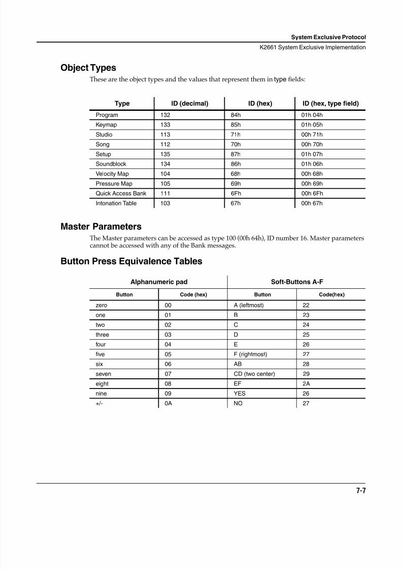
8/21/2019 MR_K2661
http://slidepdf.com/reader/full/mrk2661 69/499
System Exclusive Protocol
K2661 System Exclusive Implementation
7-7
Object TypesThese are the object types and the values that represent them in type fields:
Master ParametersThe Master parameters can be accessed as type 100 (00h 64h), ID number 16. Master parameterscannot be accessed with any of the Bank messages.
Button Press Equivalence Tables
Type ID (decimal) ID (hex) ID (hex, type field)
Program 132 84h 01h 04h
Keymap 133 85h 01h 05h
Studio 113 71h 00h 71h
Song 112 70h 00h 70h
Setup 135 87h 01h 07h
Soundblock 134 86h 01h 06h
Velocity Map 104 68h 00h 68h
Pressure Map 105 69h 00h 69h
Quick Access Bank 111 6Fh 00h 6Fh
Intonation Table 103 67h 00h 67h
Alphanumeric pad Soft-Buttons A-F
Button Code (hex) Button Code(hex)
zero 00 A (leftmost) 22
one 01 B 23
two 02 C 24
three 03 D 25
four 04 E 26
five 05 F (rightmost) 27
six 06 AB 28
seven 07 CD (two center) 29
eight 08 EF 2A
nine 09 YES 26
+/- 0A NO 27
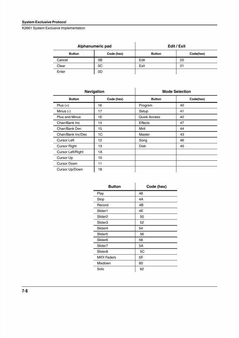
8/21/2019 MR_K2661
http://slidepdf.com/reader/full/mrk2661 70/499
7-8
System Exclusive Protocol
K2661 System Exclusive Implementation
Alphanumeric pad Edit / Exit
Button Code (hex) Button Code(hex)
Cancel 0B Edit 20
Clear 0C Exit 21
Enter 0D
Navigation Mode Selection
Button Code (hex) Button Code(hex)
Plus (+) 16 Program 40
Minus (-) 17 Setup 41
Plus and Minus 1E Quick Access 42Chan/Bank Inc 14 Effects 47
Chan/Bank Dec 15 Midi 44
Chan/Bank Inc/Dec 1C Master 43
Cursor Left 12 Song 46
Cursor Right 13 Disk 45
Cursor Left/Right 1A
Cursor Up 10
Cursor Down 11
Cursor Up/Down 18
Button Code (hex)
Play 48
Stop 4A
Record 4B
Slider1 4E
Slider2 50
Slider3 52
Slider4 54
Slider5 56
Slider6 58
Slider7 5A
Slider8 5C
MIDI Faders 5E
Mixdown 60
Solo 62
8/21/2019 MR_K2661
http://slidepdf.com/reader/full/mrk2661 71/499
System Exclusive Protocol
K2661 System Exclusive Implementation
7-9
The next four commands allow you to read the screen display, both text and graphics layers.
ALLTEXT = 15h
…requests all text in the K2661’s display.
PARAMVALUE = 16h
…requests the current parameter value.
PARAMNAME = 17h
…requests the current parameter name.
GETGRAPHICS = 18h
…requests the current graphics layer.
SCREENREPLY = 19h
This is the reply to ALLTEXT, PARAMVAL, PARAMNAME, GETGRAPHICS, orSCREENREPLY.
The reply to ALLTEXT will be 320 bytes of ASCII text (the display has 8 rows of 40 characterseach). If you receive less than that, then the screen was in the middle of redrawing and youshould request the display again.
The reply to PARAMVALUE will be a variable length ASCII text string. Some values (likekeymaps, programs, samples, etc.) include their ID number in the text string (for example,983 OB Wave 1). Some messages are also padded with extra spaces.
The reply to PARAMNAME will be a variable length ASCII text string. In cases where there is noparameter name (like on the program page) there will just be the single 00 null terminator.
The reply to GETGRAPHICS will be 2560 bytes of information. The 6 least significant bits ofeach byte indicate whether a pixel is on or off. If pixels are on over characters, the text becomesinverted. Characters on the K2661 display are a monospaced font with a height of 8 pixels and awidth of 6 pixels.
8/21/2019 MR_K2661
http://slidepdf.com/reader/full/mrk2661 72/499
7-10
System Exclusive Protocol
K2661 System Exclusive Implementation
8/21/2019 MR_K2661
http://slidepdf.com/reader/full/mrk2661 73/499
Maintenance and Troubleshooting
Preventive Maintenance
8-1
Chapter 8
Maintenance and Troubleshooting
Preventive MaintenanceWith a modicum of care, your K2661 will give you years of use and enjoyment. There are just afew important points to keep in mind.
Proper installation is essential to the health and welfare of your K2661. It should always rest ona hard flat surface—and on its rubber feet, not on the bottom panel.
Never block the ventilation openings; doing so can cause overheating that will seriously damageyour K2661. To provide adequate ventilation, the rear panel should be at least four inches from
any vertical surface. Try to minimize the amount of dust in the environment.The K2661’s RAM backup battery, along with any sample RAM, or ROM block options you mayinstall, are the only user-serviceable parts in the K2661. The only part you should everdisassemble on your K2661 is the access panel on the bottom of the instrument—removinganything else will void your product warranty.
Cleaning Your K2661It’s a good idea to remove dust from your K2661 occasionally. You may also want to removefingerprints. You can clean the K2661’s front panel with a soft damp cloth, and use a mild soapor detergent. Never use strong cleaners or solvents, and never spray anything on the front panelor into the ventilation holes. Any cleaners you may want to use should be applied to yourcleaning cloth; you can then carefully wipe the surfaces of the K2661.
8/21/2019 MR_K2661
http://slidepdf.com/reader/full/mrk2661 74/499
8-2
Maintenance and Troubleshooting
Battery Replacement
Battery ReplacementThe K2661 uses a 3-volt lithium coin-cell battery (CR2032) for program RAM backup (sampleRAM is not battery-backed). Unlike a typical alkaline battery—whose voltage output declines
over the life of the battery—a lithium cell maintains a stable voltage until it’s almost out ofpower. Once it has used up almost all of its power, however, its voltage drops rapidly.Consequently, to avoid the risk of losing the contents of your program RAM, you should replacethe battery as soon as your K2661 warns of low battery voltage.
The battery in your K2661 will last for several years.You’ll know the battery is losing powerwhen the display says BATTERY VOLTAGE IS LOW during powerup. When you see thiswarning, replace the battery as soon as possible.
Replacing the battery requires you to open an access panel on the underside of your instrument.This is the same panel you would open to install sample RAM, or ROM sound block options.
1. Obtain a CR2032 lithium coin cell; any store that sells batteries for small electronicappliances is likely to have them in stock.
2. Make sure you have backups of any RAM objects (not including samples) in the K2661that you really care about. A quick way to make backups is to use the save function inDisk mode, and choose to save everything instead of choosing one bank at a time.
Warning : Turn off your K2661 and disconnect the power cable!
3. Carefully place your K2661 upside down on a padded level surface, with the front of theinstrument toward you. Use soft, sturdy foam under the ends of the instrument, to protectthe wheels and sliders.
4. Locate the access panel. It’s about 6 by 13 inches in size, slightly to the right of center,toward the back of the instrument.
5. Remove the screws that hold the access panel in place, and swing the panel open from thefront. It hinges at the back, and rests in a position that’s convenient for referring to thediagram that’s printed on the inside of the panel.
6. Locate the battery slot. It’s toward the far edge of the circuit board, toward the rear of theinstrument.
7. Put the new battery in an easily-accessible location. Once you remove the old battery,you’ll have about 30 seconds to install the new one before you lose data from programRAM. If you install the new battery within 30 seconds, you probably won’t have to reloadany program-RAM objects.
8. To snap the old battery out of its retaining clip, lift up on the front of the battery (there’s anotch at the front of the clip, where you can get a bit of leverage), then push the batterytoward you from behind. If necessary, carefully use a small screwdriver or other object topush the battery out.
9. Snap the new battery in place, with the plus side up. Make sure that it snaps securely intothe retaining clip.
10. Replace the access panel and loosely install the screws, starting with those closest to thehinge (the back) of the access panel. When the screws are loosely in place, tighten them all.
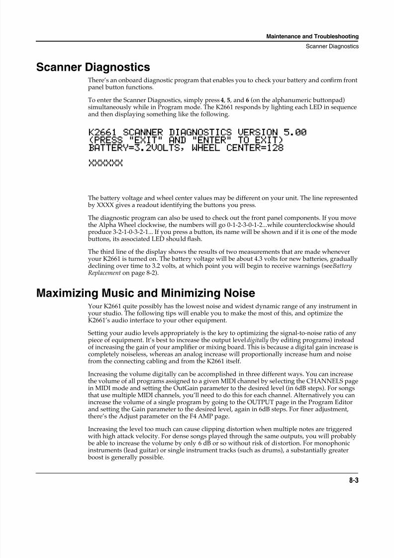
8/21/2019 MR_K2661
http://slidepdf.com/reader/full/mrk2661 75/499
Maintenance and Troubleshooting
Scanner Diagnostics
8-3
Scanner DiagnosticsThere’s an onboard diagnostic program that enables you to check your battery and confirm frontpanel button functions.
To enter the Scanner Diagnostics, simply press 4 , 5 , and 6 (on the alphanumeric buttonpad)simultaneously while in Program mode. The K2661 responds by lighting each LED in sequenceand then displaying something like the following.
K2661 SCANNER DIAGNOSTICS VERSION 5.00(PRESS "EXIT" AND "ENTER" TO EXIT)BATTERY=3.2VOLTS, WHEEL CENTER=128
XXXXXX
The battery voltage and wheel center values may be different on your unit. The line represented by XXXX gives a readout identifying the buttons you press.
The diagnostic program can also be used to check out the front panel components. If you movethe Alpha Wheel clockwise, the numbers will go 0-1-2-3-0-1-2...while counterclockwise shouldproduce 3-2-1-0-3-2-1... If you press a button, its name will be shown and if it is one of the mode buttons, its associated LED should flash.
The third line of the display shows the results of two measurements that are made wheneveryour K2661 is turned on. The battery voltage will be about 4.3 volts for new batteries, graduallydeclining over time to 3.2 volts, at which point you will begin to receive warnings (see BatteryReplacement on page 8-2).
Maximizing Music and Minimizing NoiseYour K2661 quite possibly has the lowest noise and widest dynamic range of any instrument inyour studio. The following tips will enable you to make the most of this, and optimize theK2661’s audio interface to your other equipment.
Setting your audio levels appropriately is the key to optimizing the signal-to-noise ratio of anypiece of equipment. It’s best to increase the output level digitally (by editing programs) insteadof increasing the gain of your amplifier or mixing board. This is because a digital gain increase iscompletely noiseless, whereas an analog increase will proportionally increase hum and noisefrom the connecting cabling and from the K2661 itself.
Increasing the volume digitally can be accomplished in three different ways. You can increasethe volume of all programs assigned to a given MIDI channel by selecting the CHANNELS page
in MIDI mode and setting the OutGain parameter to the desired level (in 6dB steps). For songsthat use multiple MIDI channels, you’ll need to do this for each channel. Alternatively you canincrease the volume of a single program by going to the OUTPUT page in the Program Editorand setting the Gain parameter to the desired level, again in 6dB steps. For finer adjustment,there’s the Adjust parameter on the F4 AMP page.
Increasing the level too much can cause clipping distortion when multiple notes are triggeredwith high attack velocity. For dense songs played through the same outputs, you will probably be able to increase the volume by only 6 dB or so without risk of distortion. For monophonicinstruments (lead guitar) or single instrument tracks (such as drums), a substantially greater boost is generally possible.
8/21/2019 MR_K2661
http://slidepdf.com/reader/full/mrk2661 76/499
8-4
Maintenance and Troubleshooting
Maximizing Music and Minimizing Noise
For the absolute maximum signal quality (with the exception of digital output, of course), usethe separate analog outputs. These are connected almost directly to the 18-bit digital-to-analogconverters with a minimum of noise-inducing processing circuitry. A total dynamic range ofover 100dB is available at these outputs. The MIX outputs are naturally somewhat noisier because they represent the noise of the individual outputs mixed together, and the signal musttravel through more circuitry to reach them.
Ground HumA common problem with all electrical musical gear is the hum that can occur in connectingcables due to AC ground loops. The best way to avoid ground loop noise when integrating theK2661 into a stage or studio environment is to use the K2661’s balanced audio outputs, and to besure that the mixing board, amplifier, or other equipment receiving the K2661 audio signal has a balanced input circuit.
If you can’t use the K2661 audio outputs in a balanced manner, there are a few things you can doto reduce ground hum. Although “3-prong to 2-prong” AC adapters are frequently used to break ground loops, they also break the safety ground that protects you from electric shock.
These adapters can be dangerous; don’t use them! Furthermore, although using these adaptersmay reduce low-frequency hum, high-frequency line noise (such as motor switching noise) islikely to get worse in this case, since the K2661’s AC noise filter will have no output for the noiseit filters if you disable the ground.
You can effectively reduce hum by increasing your output signal levels as described in theprevious section. Other safe procedures include plugging your mixing board and amplifier intothe same AC output as your K2661, and making sure that all of your gear is properly grounded.If you’re using an external SCSI device, plug it into the same outlet as well.
AC isolation transformers are extremely effective at eliminating ground loops, and arerecommended for critical installations in which you can’t use the K2661’s balanced outputs.A 75-watt transformer is suf ficient for the K2661.
Use the shortest possible cable, with the heaviest possible ground (shield) wire, to connect yourK2661 to the mixing board or amplifier. This helps to reduce the potential difference between thechassis of the K2661 and the chassis of a mixing board or amplifier that has unbalanced inputs—thus reducing the level of ground hum.
Finally, magnetic fields can be a source of interference. The area surrounding the K2661’s AlphaWheel and alphanumeric buttonpad is sensitive to fields from large transformers in poweramps; keep them at least a foot away from the K2661’s front panel. Smaller gear like drummachines and hardware sequencers can also cause interference.
8/21/2019 MR_K2661
http://slidepdf.com/reader/full/mrk2661 77/499
Maintenance and Troubleshooting
Power Problems and Solutions
8-5
Power Problems and SolutionsThe K2661 is quite tolerant of voltage fluctuations, noise, and transients in the AC power itreceives. The input line filter and grounded power cable will protect against even large amounts
of noise from motors and the like while the built-infi
lter coupled with the fuse will protectagainst all but the largest transients. If your installation is actually suffering from line noise ortransients, most likely your other equipment will be suffering more than your K2661.
Very low line voltage or severe voltage dips are a problem for any computer-based instrument.When the K2661 is set for 120 volt input (the normal North American setting), it should functiondown to 90 volts. If the line voltage drops below 90 volts, a special circuit halts all activity toprotect against software crashes or damage. When the line voltage returns to and stays at anacceptable level for at least one second, the computer will automatically restart. The net effect is just as if you had performed a soft reset. Continuous low line voltage or transient dips will neverproduce symptoms other than unexpected soft resets as just described. Any other problems suchas distortion, disk errors, or lost data are caused by something other than line voltagefluctuations.
Soft resets from line voltage dips are most common. These are easily identified because the resetoccurs coincident with the building lights dimming, stage lights or power amps being switchedon, or air-conditioning equipment starting up. The solution in all cases is to get a more directconnection between your K2661 (and any other computer-based equipment) and the building’spower. Floodlights, large power amplifiers, and motor-operated devices should use a separateextension cord; preferably they should be plugged into a separate circuit.
Chronic low line voltage is best confirmed by measurement. Readings below 100-105 volts meanthat even small dips could cause resets, while readings below 95 volts (accounting for meterinaccuracies) are a definite problem. Again, the best solution is to separate your heavy lightingand amplifier loads from your K2661 and other synths on separate extension cords or separatecircuits when possible. If the actual building voltage is that low, we recommend using anexternal step-up transformer or voltage regulator. We do not recommend changing the linevoltage selector to 100 volts (or 230 volts in Europe) because overheating or blown fuses mayoccur if you leave the K2661 at the lower setting and use it later at a normal voltage level.
TroubleshootingIf you’re not seeing the proper display or hearing the sounds you expect, carefully check thefollowing things:
• Make sure that your power supply is at the right voltage, and is functioning properly.
• Make sure the power cable is connected properly.
• Adjust the display contrast and brightness if necessary (there are two knobs on the rearpanel). If you still have trouble seeing the display, it’s time to contact your dealer.
• Make sure your audio cables are fully connected to the K2661 and to your sound system.You may want to switch your audio cables, unless you’re sure they’re functioning properly.
• Check that the K2661’s Volume slider is at least partially up.
• Check the volume level of your sound system.
• Lower the volume of your sound system, and turn the K2661 off, then on again (this is calleda power cycle).
• Press the +/- , 0 , and Clear buttons (on the alphanumeric buttonpad) at the same time. This iscalled a soft reset.
8/21/2019 MR_K2661
http://slidepdf.com/reader/full/mrk2661 78/499
8-6
Maintenance and Troubleshooting
Troubleshooting
• As a last resort, save any RAM objects you’ve created to disk or SmartMedia, and perform ahard reset. Do this by pressing the Master-mode button, followed by the MAST2 soft button, then pressing the Reset soft button (at the lower right of the display). The K2661 willwarn you about deleting everything (only RAM objects will be deleted). Press Yes. After afew seconds, the power-up display should appear.
Other Possible Problems
No Sound, No Display, No LEDs Illuminated
1. AC line cord not fully inserted into outlet or unit. If using a multiple outlet box, check itsplug.
2. Power not on at AC power source (wall outlet). Check with a different appliance.
3. Power switch not on (either the unit or multiple outlet box).
4. Incorrect voltage selection setting. REFER TO QUALIFIED SERVICE PERSONNEL.
No Sound
1. Volume control turned all the way down on the K2661 or on amplifier or mixer.
2. Amplifier or mixer not turned on.
3. Cabling is not correct; see Chapter 2 of the Musician’s Guide , and read about the variouscable connections you need to make: power, audio, MIDI. There’s more about audioconfigurations in Chapter 19 of the Musician’s Guide. Also check that your amplifier, mixerand speaker connections are correct.
4. MIDI volume has been assigned to a control source which has sent a value of 0. Pressing
the Panic soft button will reset all controls, and resolve this problem.
Left MIX Output Seems Louder Than Right MIX Output When Used Individually
This is normal. When a cable is plugged into the left MIX output alone, both the left AND theright audio signals are routed to the jack. When a cable is plugged into the right MIX outputalone, only the right channel audio signal is heard.
Volume Knob Has No Effect
1. Separate outputs are in use; the volume knob does not affect the separate outputs.
2. MIDI volume has been assigned to a control source which has sent a value of 0.
Programs, Setups, Songs, or Other Objects Are Missing
Battery has run down or has been disconnected. If the battery has failed, the message “Batteryvoltage is low - X.X volts” (where X.X is less than 3.0) will appear in the display on powerup. Alluser data will be permanently lost if this occurs. See Battery Replacement on page 8-2.
No Signal at ADAT In
To use ADAT In, the K2661's ADAT Out cable must also be connected to the sending device.Since the K2661 must be the “master,” the other device(s) must “slave” to it.
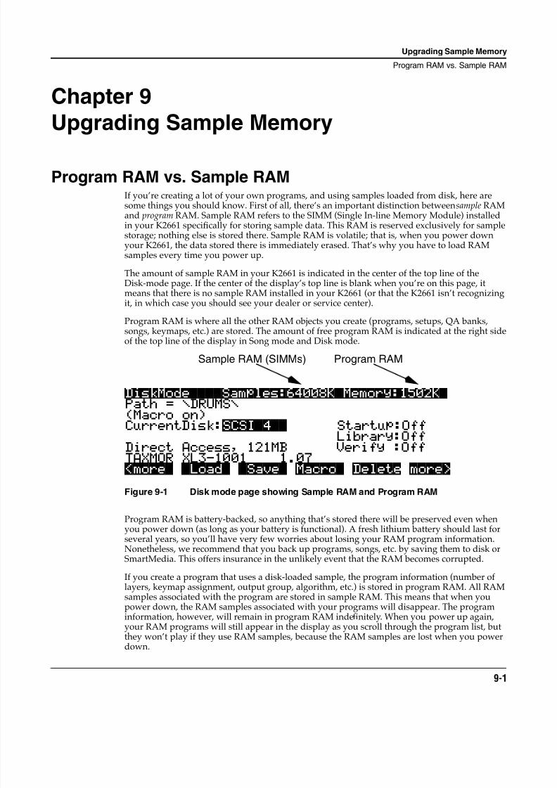
8/21/2019 MR_K2661
http://slidepdf.com/reader/full/mrk2661 79/499
Upgrading Sample Memory
Program RAM vs. Sample RAM
9-1
Chapter 9
Upgrading Sample Memory
Program RAM vs. Sample RAMIf you’re creating a lot of your own programs, and using samples loaded from disk, here aresome things you should know. First of all, there’s an important distinction between sample RAMand program RAM. Sample RAM refers to the SIMM (Single In-line Memory Module) installedin your K2661 specifically for storing sample data. This RAM is reserved exclusively for samplestorage; nothing else is stored there. Sample RAM is volatile; that is, when you power downyour K2661, the data stored there is immediately erased. That’s why you have to load RAMsamples every time you power up.
The amount of sample RAM in your K2661 is indicated in the center of the top line of theDisk-mode page. If the center of the display’s top line is blank when you’re on this page, itmeans that there is no sample RAM installed in your K2661 (or that the K2661 isn’t recognizingit, in which case you should see your dealer or service center).
Program RAM is where all the other RAM objects you create (programs, setups, QA banks,songs, keymaps, etc.) are stored. The amount of free program RAM is indicated at the right sideof the top line of the display in Song mode and Disk mode.
Figure 9-1 Disk mode page showing Sample RAM and Program RAM
Program RAM is battery-backed, so anything that’s stored there will be preserved even whenyou power down (as long as your battery is functional). A fresh lithium battery should last forseveral years, so you’ll have very few worries about losing your RAM program information.
Nonetheless, we recommend that you back up programs, songs, etc. by saving them to disk orSmartMedia. This offers insurance in the unlikely event that the RAM becomes corrupted.
If you create a program that uses a disk-loaded sample, the program information (number oflayers, keymap assignment, output group, algorithm, etc.) is stored in program RAM. All RAMsamples associated with the program are stored in sample RAM. This means that when youpower down, the RAM samples associated with your programs will disappear. The programinformation, however, will remain in program RAM indefinitely. When you power up again,your RAM programs will still appear in the display as you scroll through the program list, butthey won’t play if they use RAM samples, because the RAM samples are lost when you powerdown.
DiskMode||||Samples:64008K|Memory:1502K|Path = \DRUMS\
(Macro on) |||||||| CurrentDisk:SCSI|4|| Startup:Off
Library:OffDirect Access, 121MB Verify :OffTAXMOR XL3-1001||||1.07|||| |||||| |||||<more| |Load| |Save| Macro| Delete more>
Sample RAM (SIMMs) Program RAM
8/21/2019 MR_K2661
http://slidepdf.com/reader/full/mrk2661 80/499
9-2
Upgrading Sample Memory
Choosing and Installing a SIMM for K2661 Sample Memory
Viewing RAM ObjectsIf you’re a heavy Disk-mode user, you’ll often be faced with the decision to overwrite, merge, orappend objects when you load files from disk. If you’re loading into a memory bank that’snearly full, this can be a tricky call, because if you decide to merge or append, there may not be
enough open slots in the memory bank to accommodate the objects you load. In this case, theextra objects will be loaded into the next-higher memory bank.
Things get even trickier if you save dependent objects when you save to disk. (A dependentobject is any object that’s associated with another object stored in a different memory bank—forexample, a RAM sample with ID 301 that’s used in a program with ID 200. See the discussions ofdependent objects in Chapter 13 of the Musician’s Guide. If you load a file that contains a numberof dependent objects, some of them may be loaded into a higher memory bank than the one youspecified in the Bank dialog before you loaded the file. A quick way to see where the objects youloaded ended up is to use the Objects utility function in Master mode.
Select Master mode and press the Utility soft button. Press the Objects soft button, and a list ofRAM objects will appear. Use the Alpha Wheel to scroll through the list of objects. You’ll see thetype, ID, name, and size (in bytes) of each object.
Choosing and Installing a SIMM for K2661 Sample MemoryIf your K2661 has a 64 M SIMM installed, you can replace it with a 128 M SIMM to increase yoursample memory.
SIMM SpecificationsSIMMs for sample RAM must have the following characteristics:
• 72-pin noncomposite single, in-line memory modules (SIMMs), in sizes of 64 M, or 128 M
• 8- or 9-bit
• 3-volt or 5-volt (most SIMMS currently on the market are 5-volt)
• Fast-page (FPM) or extra data output (EDO) (80-nanosecond or faster)
There is space for a single SIMM, up to a total of 128 M.
These companies make SIMMs that work with the K2661 (many other sources are also likely tohave the proper configurations):
Newer RAM (800) 678-3726 or (316) 943-0222
Chip Merchant (800) 808-2447 or (619) 268-4774
Kamel Peripherals (508) 435-7771 or (888) 295-2635
Lifetime Memory (800) 233 6233 or (714) 794-9000
Caution: Do not use composite SIMMs. A composite SIMM is one that uses a PAL or other additionalcircuitry to make multiple DRAM chips act like bigger chips. Non-composite SIMMs (acceptable) have nochips other than DRAM memory chips soldered to the board. SIMMs with PALs, buffers, or other logiccomponents will not work in a K2661; do not use them. Composite SIMMs may appear to work in somecases, but they will be unreliable.
8/21/2019 MR_K2661
http://slidepdf.com/reader/full/mrk2661 81/499
Upgrading Sample Memory
Choosing and Installing a SIMM for K2661 Sample Memory
9-3
Installing Sample RAMThere’s an access panel on the underside of your K2661, which you’ll need to open to installyour sample RAM. This is the same panel you would open to install a replacement battery orROM sound block options.
Warning : Turn off your K2661 and disconnect the power cable!
1. Carefully place your K2661 upside down on a padded level surface, with the front of theinstrument toward you. Use soft, sturdy foam under the ends of the instrument, to protectthe wheels and sliders.
2. Locate the access panel. It’s about 6 by 13 inches in size, slightly to the right of center,toward the back of the instrument.
3. Remove the eight screws that hold the access panel in place, and swing the panel openfrom the front. It hinges at the back, and rests in a position that’s convenient for referring
to the diagram that’s printed on the inside of the panel.
4. Locate the socket for sample RAM.
5. Remove the installed SIMM and store it in a static-proof bag.
6. Place the new SIMM into the sample RAM socket. There’s only one way that a SIMM willfit into the socket. Be sure the clips at the sides of the sockets snap into place.
7. Check the setting of the voltage jumper, and change it if it doesn’t match the voltage ofyour SIMMs. The K2661 arrives from the factory with the jumper set for 3-volt SIMMs.Since most SIMMs these days are 5-volt, you’ll probably need to change the jumpersetting.
The jumper is a small piece of molded plastic with a wire loop at the top. It has two slotsthat slide over two of the three pins that stick up from the circuit board. The pins arenumbered from 1 to 3, right-to-left. Put the jumper on pins 2 and 1 (the two right-mostpins) to configure the K2661 for 5-volt SIMMs, or on pins 3 and 2 (the two left-most pins)to configure it for 3-volt SIMMS. The circuit board is labeled accordingly.
We set the configuration for 3 volts so that if you were to install 3-volt SIMMs whilethinking you were installing 5-volt SIMMS, you wouldn’t pose any risk to yourinstrument.
8. Replace the access panel and loosely install the screws, starting with those closest to thehinge (the back) of the access panel. When the screws are loosely in place, tighten them all.

8/21/2019 MR_K2661
http://slidepdf.com/reader/full/mrk2661 82/499
9-4
Upgrading Sample Memory
Choosing and Installing a SIMM for K2661 Sample Memory
8/21/2019 MR_K2661
http://slidepdf.com/reader/full/mrk2661 83/499
KDFX Reference
In This Chapter
10-1
Chapter 10
KDFX Reference
In This Chapter• KDFX Algorithms. . . . . . . . . . . . . . . . . . . . . . . . . . . . . . . . . . . . 10-2
• FX Presets. . . . . . . . . . . . . . . . . . . . . . . . . . . . . . . . . . . . . . . . . . . 10-3
• KDFX Studios . . . . . . . . . . . . . . . . . . . . . . . . . . . . . . . . . . . . . . . 10-5
• KDFX Algorithm Specifications . . . . . . . . . . . . . . . . . . . . . . . . 10-6
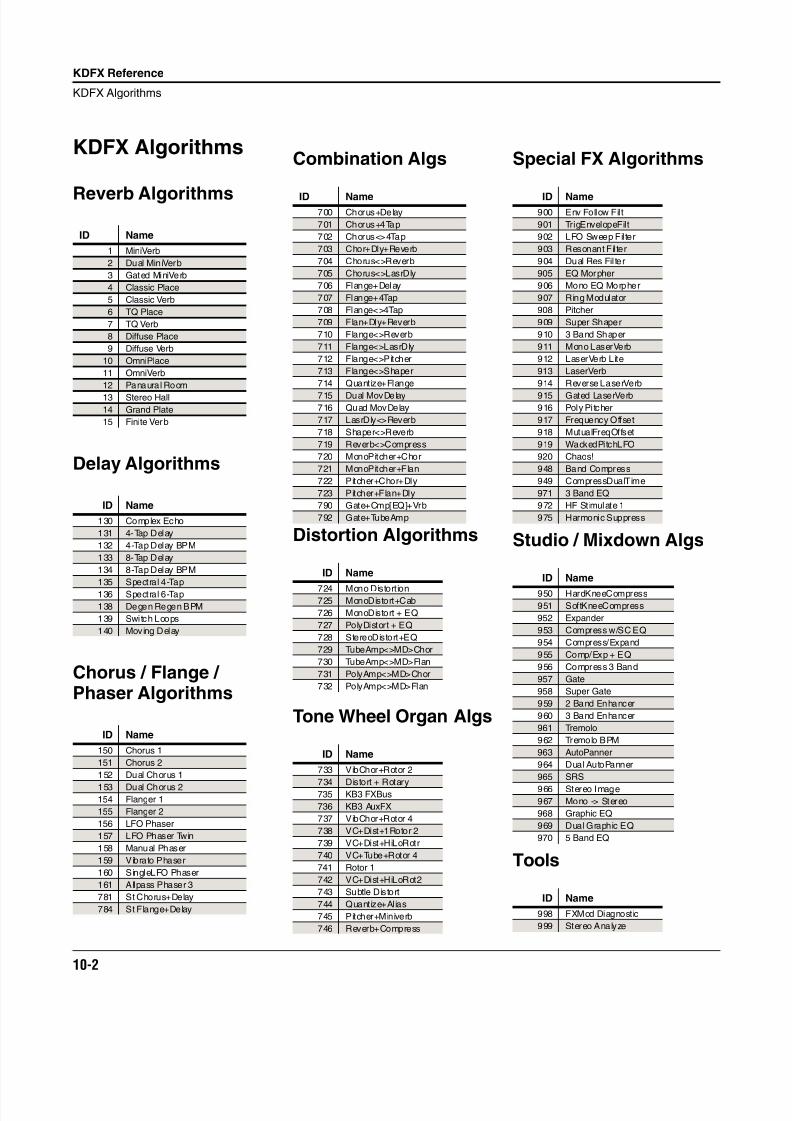
8/21/2019 MR_K2661
http://slidepdf.com/reader/full/mrk2661 84/499
10-2
KDFX Reference
KDFX Algorithms
KDFX Algorithms
Reverb Algorithms
Delay Algorithms
Chorus / Flange /Phaser Algorithms
ID Name
1 MiniVerb
2 Dual MiniVerb
3 Gated MiniVerb
4 Classic Place
5 Classic Verb
6 TQ Place
7 TQ Verb
8 Diffuse Place
9 Diffuse Verb
10 OmniPlace
11 OmniVerb
12 Panaural Room
13 Stereo Hall
14 Grand Plate
15 Finite Verb
ID Name
130 Complex Echo
131 4-Tap Delay
132 4-Tap Delay BPM
133 8-Tap Delay
134 8-Tap Delay BPM
135 Spectral 4-Tap
136 Spectral 6-Tap
138 Degen Regen BPM
139 Switch Loops
140 Moving Delay
ID Name
150 Chorus 1
151 Chorus 2
152 Dual Chorus 1
153 Dual Chorus 2154 Flanger 1
155 Flanger 2
156 LFO Phaser
157 LFO Phaser Twin
158 Manual Phaser
159 Vibrato Phaser
160 SingleLFO Phaser
161 Allpass Phaser 3
781 St Chorus+Delay
784 St Flange+Delay
Combination Algs
Distortion Algorithms
Tone Wheel Organ Algs
ID Name700 Chorus+Delay
701 Chorus+4Tap
702 Chorus<>4Tap
703 Chor+Dly+Reverb
704 Chorus<>Reverb
705 Chorus<>LasrDly
706 Flange+Delay
707 Flange+4Tap
708 Flange<>4Tap
709 Flan+Dly+Reverb
710 Flange<>Reverb
711 Flange<>LasrDly
712 Flange<>Pitcher
713 Flange<>Shaper
714 Quantize+Flange
715 Dual MovDelay
716 Quad MovDelay
717 LasrDly<>Reverb
718 Shaper<>Reverb
719 Reverb<>Compress
720 MonoPitcher+Chor
721 MonoPitcher+Flan
722 Pitcher+Chor+Dly
723 Pitcher+Flan+Dly
790 Gate+Cmp[EQ]+Vrb
792 Gate+TubeAmp
ID Name
724 Mono Distort ion725 MonoDistort+Cab
726 MonoDistort + EQ
727 PolyDistort + EQ
728 StereoDistort+EQ
729 TubeAmp<>MD>Chor
730 TubeAmp<>MD>Flan
731 PolyAmp<>MD>Chor
732 PolyAmp<>MD>Flan
ID Name
733 VibChor+Rotor 2
734 Distort + Rotary735 KB3 FXBus
736 KB3 AuxFX
737 VibChor+Rotor 4
738 VC+Dist+1Rotor 2
739 VC+Dist+HiLoRotr
740 VC+Tube+Rotor 4
741 Rotor 1
742 VC+Dist+HiLoRot2
743 Subtle Distort
744 Quantize+Alias
745 Pitcher+Miniverb
746 Reverb+Compress
Special FX Algorithms
Studio / Mixdown Algs
Tools
ID Name900 Env Follow Filt
901 TrigEnvelopeFilt
902 LFO Sweep Filter
903 Resonant Fil ter
904 Dual Res Fil ter
905 EQ Morpher
906 Mono EQ Morpher
907 Ring Modulator
908 Pitcher
909 Super Shaper
910 3 Band Shaper
911 Mono LaserVerb
912 LaserVerb Lite
913 LaserVerb
914 Reverse LaserVerb
915 Gated LaserVerb
916 Poly Pi tcher
917 Frequency Offset
918 MutualFreqOffset
919 WackedPitchLFO
920 Chaos!
948 Band Compress
949 CompressDualTime
971 3 Band EQ
972 HF St imulate 1
975 Harmonic Suppress
ID Name
950 HardKneeCompress
951 SoftKneeCompress
952 Expander
953 Compress w/SC EQ
954 Compress/Expand
955 Comp/Exp + EQ
956 Compress 3 Band
957 Gate
958 Super Gate
959 2 Band Enhancer
960 3 Band Enhancer
961 Tremolo
962 Tremolo BPM
963 AutoPanner
964 Dual AutoPanner
965 SRS
966 Stereo Image
967 Mono -> Stereo
968 Graphic EQ
969 Dual Graphic EQ
970 5 Band EQ
ID Name
998 FXMod Diagnostic
999 Stereo Analyze
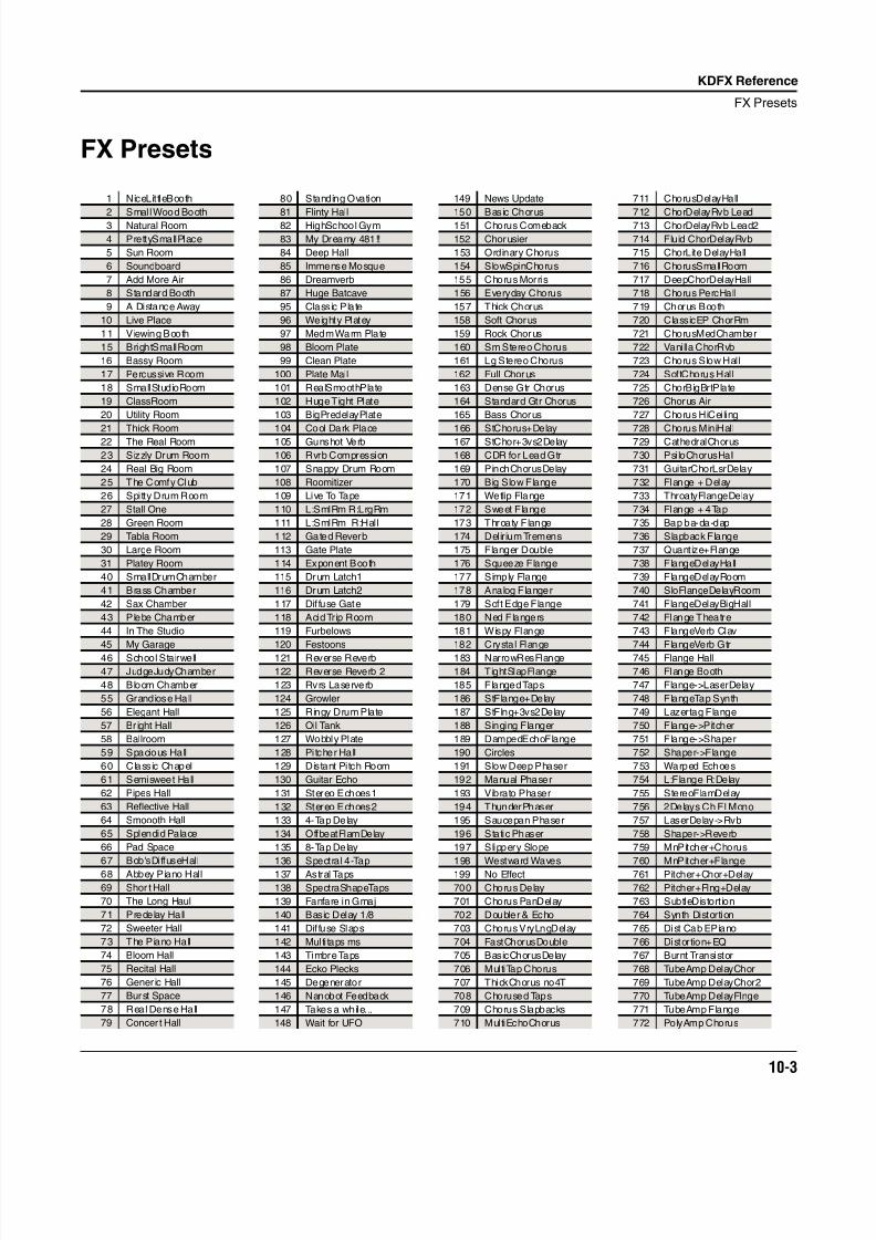
8/21/2019 MR_K2661
http://slidepdf.com/reader/full/mrk2661 85/499
KDFX Reference
FX Presets
10-3
FX Presets
1 NiceLittleBooth
2 Smal l Wood Booth3 Natural Room
4 PrettySmallPlace
5 Sun Room
6 Soundboard
7 Add More Air
8 Standard Booth
9 A Distance Away
10 Live Place
11 Viewing Booth
15 BrightSmallRoom
16 Bassy Room
17 Percussive Room
18 SmallStudioRoom
19 ClassRoom
20 Utility Room
21 Thick Room
22 The Real Room
23 Sizzly Drum Room
24 Real Big Room
25 The Comfy Club
26 Spitty Drum Room
27 Stall One
28 Green Room
29 Tabla Room
30 Large Room
31 Platey Room
40 SmallDrumChamber
41 Brass Chamber
42 Sax Chamber
43 Plebe Chamber
44 In The Studio
45 My Garage
46 School Stairwell
47 JudgeJudyChamber
48 Bloom Chamber
55 Grandiose Hall
56 Elegant Hall
57 Br ight Hall
58 Ballroom
59 Spacious Hall
60 Classic Chapel
61 Semisweet Hall
62 Pipes Hall
63 Reflective Hall
64 Smoooth Hall
65 Splendid Palace
66 Pad Space
67 Bob'sDiffuseHall
68 Abbey Piano Hall
69 Shor t Hall
70 The Long Haul
71 Predelay Hall
72 Sweeter Hall
73 The Piano Hall
74 Bloom Hall
75 Recital Hall
76 Gener ic Hall
77 Burst Space
78 Real Dense Hall
79 Concer t Hall
80 Standing Ovation
81 Flinty Hall82 HighSchool Gym
83 My Dreamy 481!!
84 Deep Hall
85 Immense Mosque
86 Dreamverb
87 Huge Batcave
95 Classic Plate
96 Weighty Platey
97 Medm Warm Plate
98 Bloom Plate
99 Clean Plate
100 Plate Mail
101 RealSmoothPlate
102 Huge Tight Plate
103 BigPredelayPlate
104 Cool Dark Place
105 Gunshot Verb
106 Rvrb Compression
107 Snappy Drum Room
108 Roomitizer
109 Live To Tape
110 L:SmlRm R:LrgRm
111 L:SmlRm R:Hall
112 Gated Reverb
113 Gate Plate
114 Exponent Booth
115 Drum Latch1
116 Drum Latch2
117 Dif fuse Gate
118 Acid Trip Room
119 Furbelows
120 Festoons
121 Reverse Reverb
122 Reverse Reverb 2
123 Rvrs Laserverb
124 Growler
125 Ringy Drum Plate
126 Oil Tank
127 Wobbly Plate
128 Pi tcher Hall
129 Distant Pitch Room
130 Guitar Echo
131 Stereo Echoes1
132 Stereo Echoes2
133 4-Tap Delay
134 OffbeatFlamDelay
135 8-Tap Delay
136 Spectral 4-Tap
137 Astral Taps
138 SpectraShapeTaps
139 Fanfare in Gmaj
140 Basic Delay 1/8
141 Dif fuse Slaps
142 Multi taps ms
143 Timbre Taps
144 Ecko Plecks
145 Degenerator
146 Nanobot Feedback
147 Takes a while...
148 Wait for UFO
149 News Update
150 Basic Chorus151 Chorus Comeback
152 Chorusier
153 Ordinary Chorus
154 SlowSpinChorus
155 Chorus Morris
156 Everyday Chorus
157 Thick Chorus
158 Soft Chorus
159 Rock Chorus
160 Sm Stereo Chorus
161 Lg Stereo Chorus
162 Full Chorus
163 Dense Gtr Chorus
164 Standard Gtr Chorus
165 Bass Chorus
166 StChorus+Delay
167 StChor+3vs2Delay
168 CDR for Lead Gtr
169 PinchChorusDelay
170 Big Slow Flange
171 Wetlip Flange
172 Sweet Flange
173 Throaty Flange
174 Delirium Tremens
175 Flanger Double
176 Squeeze Flange
177 Simply Flange
178 Analog Flanger
179 Soft Edge Flange
180 Ned Flangers
181 Wispy Flange
182 Crystal Flange
183 NarrowResFlange
184 TightSlapFlange
185 Flanged Taps
186 StFlange+Delay
187 StFlng+3vs2Delay
188 Singing Flanger
189 DampedEchoFlange
190 Circles
191 Slow Deep Phaser
192 Manual Phaser
193 Vibrato Phaser
194 ThunderPhaser
195 Saucepan Phaser
196 Static Phaser
197 Slippery Slope
198 Westward Waves
199 No Effect
700 Chorus Delay
701 Chorus PanDelay
702 Doubler & Echo
703 Chorus VryLngDelay
704 FastChorusDouble
705 BasicChorusDelay
706 MultiTap Chorus
707 ThickChorus no4T
708 Chorused Taps
709 Chorus Slapbacks
710 MultiEchoChorus
711 ChorusDelayHall
712 ChorDelayRvb Lead713 ChorDelayRvb Lead2
714 Fluid ChorDelayRvb
715 ChorLite DelayHall
716 ChorusSmallRoom
717 DeepChorDelayHall
718 Chorus PercHall
719 Chorus Booth
720 ClassicEP ChorRm
721 ChorusMedChamber
722 Vanilla ChorRvb
723 Chorus Slow Hall
724 SoftChorus Hall
725 ChorBigBrtPlate
726 Chorus Air
727 Chorus HiCeiling
728 Chorus MiniHall
729 CathedralChorus
730 PsiloChorusHall
731 GuitarChorLsrDelay
732 Flange + Delay
733 ThroatyFlangeDelay
734 Flange + 4Tap
735 Bap ba-da-dap
736 Slapback Flange
737 Quantize+Flange
738 FlangeDelayHall
739 FlangeDelayRoom
740 SloFlangeDelayRoom
741 FlangeDelayBigHall
742 Flange Theatre
743 FlangeVerb Clav
744 FlangeVerb Gtr
745 Flange Hall
746 Flange Booth
747 Flange->LaserDelay
748 FlangeTap Synth
749 Lazertag Flange
750 Flange->Pitcher
751 Flange->Shaper
752 Shaper->Flange
753 Warped Echoes
754 L:Flange R:Delay
755 StereoFlamDelay
756 2Delays Ch Fl Mono
757 LaserDelay->Rvb
758 Shaper->Reverb
759 MnPitcher+Chorus
760 MnPitcher+Flange
761 Pitcher+Chor+Delay
762 Pitcher+Flng+Delay
763 SubtleDistort ion
764 Synth Distortion
765 Dist Cab EPiano
766 Distortion+EQ
767 Burnt Transistor
768 TubeAmp DelayChor
769 TubeAmp DelayChor2
770 TubeAmp DelayFlnge
771 TubeAmp Flange
772 PolyAmp Chorus
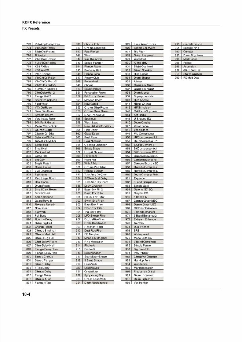
8/21/2019 MR_K2661
http://slidepdf.com/reader/full/mrk2661 86/499
10-4
KDFX Reference
FX Presets
773 PolyAmp DelayFlnge
774 VibrChor Rotors
775 SlightDistRotors
776 Rotostor t
777 VibrChor Rotors2778 Full VbCh Rotors
779 KB3 FXBus
780 KB3 AuxFX
781 Pitch Spinner
782 VibrChrDstRotor1
783 VibrChrDstRotor2
784 VibChrDstRotor3
785 FullVbChTubeRotr
786 ChorDelayHall 2
787 Flange Hal l 2
788 SpeeChorusDeep
789 Fluid Wash
790 VC+DistRotor
791 Slow Res Rotor
792 Smooth Rotors
793 Very Nazty Rotor794 80’s Funk Guitar
795 Mean 70’sFunkGtr
796 Crunch Gui tar
797 Classic Gtr Dist
798 SaturatedGtrDist
799 TubeDist DlyChor
800 Sweet Hall
801 Small Hall
802 Medium Hall
803 Large Hall
804 Big Gym
805 Bright Plate 1
806 Opera House
807 Live Chamber
808 Bathroom
809 Med Large Room810 Real Room
811 Drum Room
812 Small Dark Room
813 Smal l Closet
814 Add Ambience
815 Gated Reverb
816 Reverse Reverb
817 Non-Linear
818 Slapverb
819 Full Bass
820 Room + Delay
821 Delay Big Hall
822 Chorus Room
823 Chorus Smallhall
824 Chorus Med Hal l
825 Chorus Big Hall
826 Chor-Delay Room
827 Chor-Delay Hall
828 Flange-Delay Room
829 Flange-Delay Hall
830 Stereo Chorus
831 Stereo Flanger
832 Stereo Delay
833 4-Tap Delay
834 Chorus Delay
835 Flange Delay
836 Chorus 4-Tap
837 Flange 4 Tap
838 Chorus Echo
839 Chorus Echoverb
840 Fast Flange
841 Wash
842 Into The Abyss843 Space Flanger
844 Flange Room
845 Predelay Hall
846 Flange Echo
847 Rotary Club
848 Rotary Hall
849 Chorus
850 Soundbrd/rvb
851 Percussive Room
852 Brt Empty Room
853 Mosque Room
854 New Gated
855 Chorus Slap Room
856 Chorus Bass Room
857 New Chorus Hall
858 Spacious859 Wash Lead
860 New Hall Wet/Dryelay
861 Rich Delay
862 Glass Delay
863 Real Plate
864 Real Niceverb
865 ClassicalChamber
866 Empty Stage
867 Long & Narrow
868 Far Bloom
869 Floyd Hall
870 With A Mic
881 Chorus PanDelay
882 Flange + Delay
883 TubeAmp DlyChor
884 StChor+3vs2Delay885 TubeAmp DlyChor2
886 Drum Crusher
887 Bass Env Filt 2
900 Basic Env Filter
901 Phunk Env Filter
902 Synth Env Filter
903 Bass Env Filter
904 EPno Env Filter
905 Trig Env Filter
906 LFO Sweep Filter
907 DoubleRiseFilter
908 Circle Bandsweep
909 Resonant Fil ter
910 Dual Res Fil ter
911 EQ Morpher
912 Mono EQ Morpher
913 Ring Modulator
914 PitcherA
915 PitcherB
916 SuperShaper
917 SubtleDrumShape
918 3 Band Shaper
919 LaserVerb
920 Laserwaves
921 Crystal lizer
922 Spry Young Boy
923 Cheap LaserVerb
924 Drum Neurezonate
925 LazerfazerEchoes
926 Simple Lazerverb
927 TripFi lter
928 Gated Laserverb
929 Waterford930 A litt le dirty
931 Slight Overload
932 Blown Speaker
933 Ring Linger
934 Drum Shaper
935 Aliaser
936 Quantize+Alias1
937 Quantize+Alias2
938 Drum Mortar
939 Superphasulate
940 Rich Noodle
941 Nickel Chorus
942 HF Stimulator
943 OddHarmSuppress
944 AM Radio
945 U-Shaped EQ946 Drum Crusher
947 Vocal Room
948 Vocal Stage
949 Mid Compressor
950 HKCompressor 3:1
951 DrumKompress 5:1
952 SK FB Comprs 6:1
953 SKCompressor 9:1
954 SKCompressr 12:1
955 Compress w/SC EQ
956 Compress/Expand
957 Comprs/Expnd +EQ
958 Reverb>Compress
959 Reverb>Compress2
960 Drum Comprs>Rvb
961 Expander962 3Band Compressor
963 Simple Gate
964 Gate w/ SC EQ
965 Graphic EQ
966 5 Band EQ
967 ContourGraphicEQ
968 Dance GraphicEQ
969 OldPianoEnhancer
970 3 Band Enhancer
971 3 Band Enhancer2
972 Extreem Enhancer
973 Tremolo
974 Dual Panner
975 SRS
976 Widespread
977 Mono->Stereo
978 3 Band Compress
979 Simple Panner
980 Big Bass EQ
981 Poly Pitcher
982 CheapVoxChanger
983 Hip Hop Aura
984 Woodenize
985 Marimbafication
986 Frequency Offset
987 Drum Loosener
988 Drum Tightener
989 Vox Honker
990 Glacial Canyon
991 Spring Thing
992 Contact
993 Drum Frightener
994 Mad Hatter995 Fallout
996 Ascension
997 60Hz Buzz Kil l
998 Stereo Analyze
999 FX Mod Diag
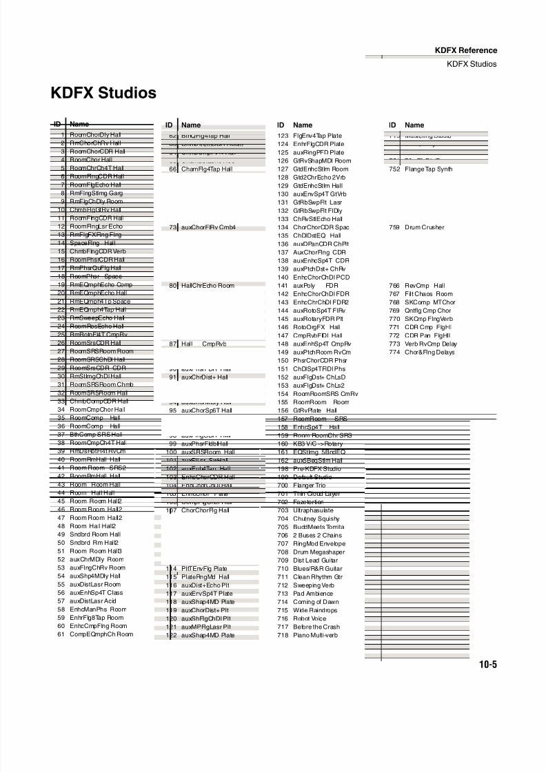
8/21/2019 MR_K2661
http://slidepdf.com/reader/full/mrk2661 87/499
KDFX Reference
KDFX Studios
10-5
KDFX Studios
ID Name
1 RoomChorDly Hall2 RmChorChRv Hall
3 RoomChorCDR Hall
4 RoomChor Hall
5 RoomChrCh4T Hall
6 RoomFlngCDR Hall
7 RoomFlgEcho Hall
8 RmFlngStImg Garg
9 RmFlgChDly Room
10 ChmbFlgGtRv Hall
11 RoomFlngCDR Hall
12 RoomFlngLsr Echo
13 RmFlgFXFlng Flng
14 SpaceFlng Hall
15 ChmbFlngCDR Verb
16 RoomPhsrCDR Hall
17 RmPhsrQuFlg Hall18 RoomPhsr Space
19 RmEQmphEcho Comp
20 RmEQmphEcho Hall
21 RmEQmph4Tp Space
22 RmEQmph4Tap Hall
23 RmSweepEcho Hall
24 RoomResEcho Hall
25 RmRotoFl4T CmpRv
26 RoomSrsCDR Hall
27 RoomSRSRoom Room
28 RoomSRSChDl Hall
29 RoomSrsCDR CDR
30 RmStImgChDl Hall
31 RoomSRSRoom Chmb
32 RoomSRSRoom Hall
33 ChmbCompCDR Hall
34 RoomCmpChor Hall
35 RoomComp Hall
36 RoomComp Hall
37 BthComp SRS Hall
38 RoomCmpCh4T Hall
39 RmDsRotFl4t RvCm
40 RoomRmHall Hall
41 Room Room SRS2
42 RoomRmHall Hall
43 Room Room Hall
44 Room Hall Hall
45 Room Room Hall2
46 Room Room Hall2
47 Room Room Hall2
48 Room Hall Hall2
49 Sndbrd Room Hall
50 Sndbrd Rm Hall251 Room Room Hall3
52 auxChrMDly Room
53 auxFlngChRv Room
54 auxShp4MDly Hall
55 auxDistLasr Room
56 auxEnhSp4T Class
57 auxDistLasr Acid
58 EnhcManPhs Room
59 EnhrFlg8Tap Room
60 EnhcCmpFlng Room
61 CompEQmphCh Room
62 BthQFlg4Tap Hall63 ChmbTremCDR Room
64 ChmbCmpFlRv Hall
65 ChamDstEcho Room
66 ChamFlg4Tap Hall
67 ChmbEnv4Tap GtRv
68 CmbrShapLsr Hall
69 auxPtchDst+ Chmb
70 auxChorFlRv Cmbr
71 auxChorFlRv Cmb2
72 auxChorFlRv Cmb3
73 auxChorFlRv Cmb4
74 HallFlgChDl Room
75 HallPtchLsr Hall
76 HallGateFl4T Bth
77 HallChorFDR Room
78 HallPtchPtFl Lsr79 HallFlng8Tp Room
80 HallChrEcho Room
81 HallChorCDR Hall
82 HallRsFltChDl Rm
83 Hall ChDly Hall
84 HallFlgChDl Hall
85 Hall Room SRS
86 Hall Room Room
87 Hall CmpRvb
88 Hall Flng Hall
89 HallRoomChr Hall
90 auxPhsrFDR Hall
91 auxChrDist+ Hall
92 auxFlgDist+ Hall
93 auxChrDst+ Hall
94 auxChorMDly Hall
95 auxChorSp6T Hall
96 auxChorChDl Hall
97 auxPhasStIm Hall
98 auxFlngCDR Hall
99 auxPhsrFldblHall
100 auxSRSRoom Hall
101 auxFlLsr SwHall
102 auxEnh4Tap Hall
103 EnhcChorCDR Hall
104 EnhChorChDl Hall
105 EnhcChor Plate
106 CompFlgChor Hall
107 ChorChorFlg Hall
108 ChapelSRS Hall
109 ChapelSRS Hall2
110 Chapel Room Hall
111 PltEnvFl4T Room
112 PlatEnvFl4T Filt
113 PltEnvFl4T Plate
114 PltTEnvFlg Plate
115 PlateRngMd Hall
116 auxDist+Echo Plt
117 auxEnvSp4T Plate
118 auxShap4MD Plate
119 auxChorDist+ Plt
120 auxShFlgChDl Plt
121 auxMPFlgLasr Plt
122 auxShap4MD Plate
ID Name
123 FlgEnv4Tap Plate124 EnhrFlgCDR Plate
125 auxRingPFD Plate
126 GtRvShapMDl Room
127 GtdEnhcStIm Room
128 Gtd2ChrEcho 2Vrb
129 GtdEnhcStIm Hall
130 auxEnvSp4T GtVrb
131 GtRbSwpFlt Lasr
132 GtRbSwpFlt FlDly
133 ChRvStIEcho Hall
134 ChorChorCDR Spac
135 ChDlDstEQ Hall
136 auxDPanCDR ChPlt
137 AuxChorFlng CDR
138 auxEnhcSp4T CDR
139 auxPtchDst+ ChRv140 EnhcChorChDl PCD
141 auxPoly FDR
142 EnhcChorChDl FDR
143 EnhcChrChDl FDR2
144 auxRotoSp4T FlRv
145 auxRotaryFDR Plt
146 RotoOrgFX Hall
147 CmpRvbFlDl Hall
148 auxEnhSp4T CmpRv
149 auxPtchRoom RvCm
150 PhsrChorCDR Phsr
151 ChDlSp4TFlDl Phs
152 auxFlgDst+ ChLsD
153 auxFlgDst+ ChLs2
154 RoomRoomSRS CmRv
155 RoomRoom Room
156 GtRvPlate Hall
157 RoomRoom SRS
158 EnhcSp4T Hall
159 Room RoomChr SRS
160 KB3 V/C ->Rotary
161 EQStImg 5BndEQ
162 aux5BeqStIm Hall
198 Pre-KDFX Studio
199 Default Studio
700 Flanger Trio
701 Thin Cloud Layer
702 Fazetortion
703 Ultraphasulate
704 Chutney Squishy
705 BuddMeets Tomita
706 2 Buses 2 Chains
707 RingMod Envelope
708 Drum Megashaper
709 Dist Lead Guitar
710 Blues/R&R Guitar
711 Clean Rhythm Gtr
712 Sweeping Verb
713 Pad Ambience
714 Coming of Dawn
715 Wide Raindrops
716 Robot Voice
717 Before the Crash
718 Piano Multi-verb
ID Name
719 Mastering Studio749 E Pno Amp
750 Tron Effects
751 70s EfxDistB
752 Flange Tap Synth
753 HlFlgChDl Rm LD1
754 Hall CabDst Hall
755 2 Bus 2 Chain 2
756 Ster ChorusDelay
757 Phsr Trpflt
758 Jazzy Room
759 Drum Crusher
760 Verb Roto Room
761 Flt Cmp Ch4T
762 DrCmpr CDR
763 Chor Cmp Verb
764 Cmpr ChrDbl765 ChorRotoCmp Rev
766 RevCmp Hall
767 Filt Chaos Room
768 SKComp MTChor
769 Qntflg Cmp Chor
770 SKCmp FlngVerb
771 CDR Cmp FlgHll
772 CDR Pan FlgHll
773 Verb RvCmp Delay
774 Chor&Flng Delays
ID Name
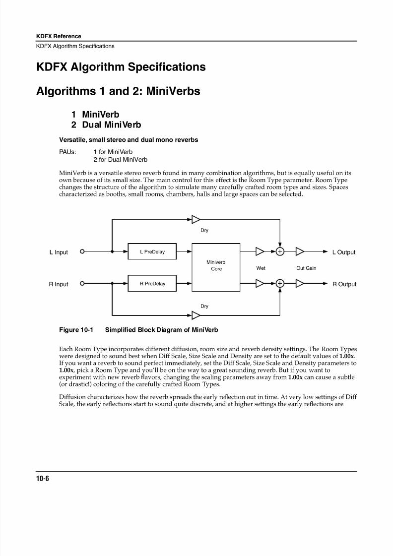
8/21/2019 MR_K2661
http://slidepdf.com/reader/full/mrk2661 88/499
10-6
KDFX Reference
KDFX Algorithm Specifications
KDFX Algorithm Specifications
Algorithms 1 and 2: MiniVerbs1 MiniVerb2 Dual MiniVerb
Versatile, small stereo and dual mono reverbs
PAUs: 1 for MiniVerb
2 for Dual MiniVerb
MiniVerb is a versatile stereo reverb found in many combination algorithms, but is equally useful on itsown because of its small size. The main control for this effect is the Room Type parameter. Room Typechanges the structure of the algorithm to simulate many carefully crafted room types and sizes. Spaces
characterized as booths, small rooms, chambers, halls and large spaces can be selected.
Figure 10-1 Simplified Block Diagram of MiniVerb
Each Room Type incorporates different diffusion, room size and reverb density settings. The Room Typeswere designed to sound best when Diff Scale, Size Scale and Density are set to the default values of 1.00x.If you want a reverb to sound perfect immediately, set the Diff Scale, Size Scale and Density parameters to1.00x , pick a Room Type and you’ll be on the way to a great sounding reverb. But if you want toexperiment with new reverb flavors, changing the scaling parameters away from 1.00x can cause a subtle(or drastic!) coloring of the carefully crafted Room Types.
Diffusion characterizes how the reverb spreads the early reflection out in time. At very low settings of DiffScale, the early reflections start to sound quite discrete, and at higher settings the early reflections are
L PreDelay
R PreDelay
Miniverb
Core
L Input
R Input
L Output
R Output
Wet Out Gain
Dry
Dry
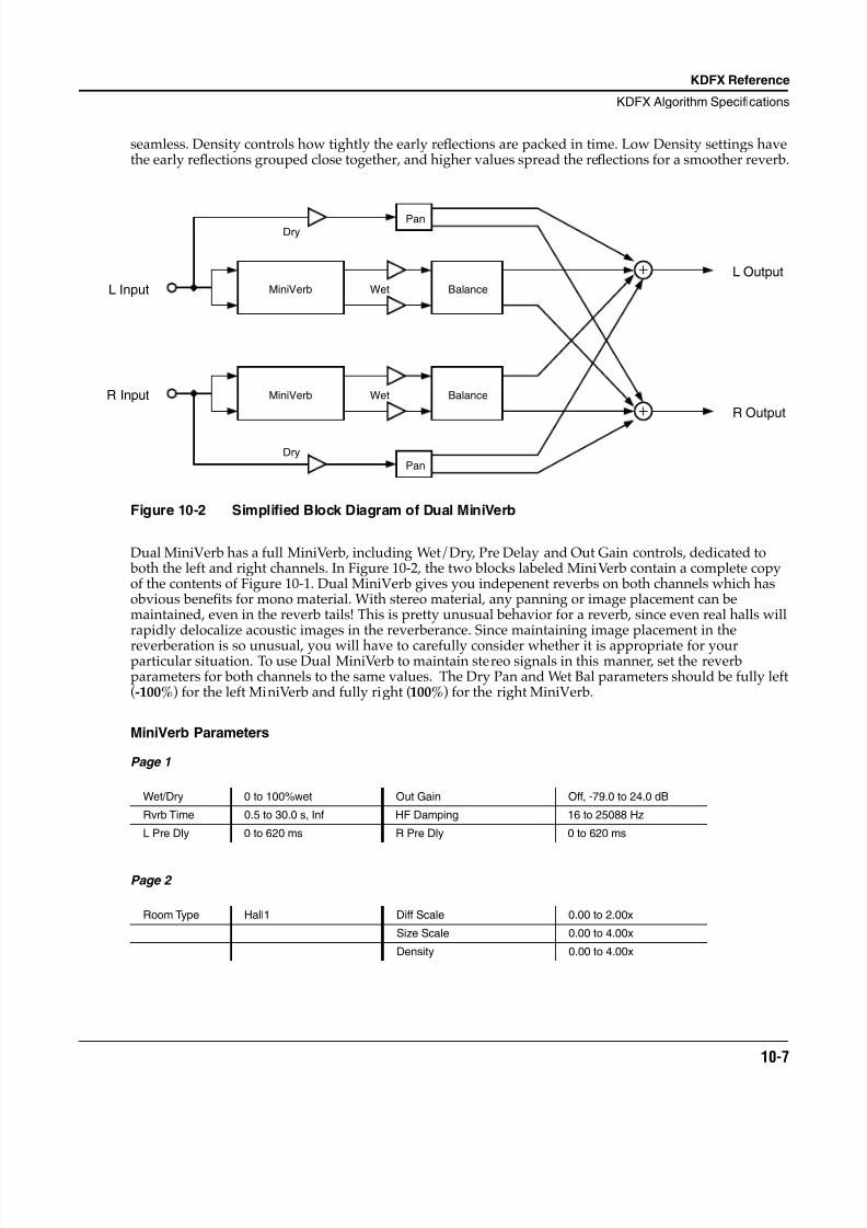
8/21/2019 MR_K2661
http://slidepdf.com/reader/full/mrk2661 89/499
KDFX Reference
KDFX Algorithm Specifications
10-7
seamless. Density controls how tightly the early reflections are packed in time. Low Density settings havethe early reflections grouped close together, and higher values spread the reflections for a smoother reverb.
Figure 10-2 Simplified Block Diagram of Dual MiniVerb
Dual MiniVerb has a full MiniVerb, including Wet/Dry, Pre Delay and Out Gain controls, dedicated to both the left and right channels. In Figure 10-2 , the two blocks labeled MiniVerb contain a complete copyof the contents of Figure 10-1. Dual MiniVerb gives you indepenent reverbs on both channels which hasobvious benefits for mono material. With stereo material, any panning or image placement can bemaintained, even in the reverb tails! This is pretty unusual behavior for a reverb, since even real halls willrapidly delocalize acoustic images in the reverberance. Since maintaining image placement in the
reverberation is so unusual, you will have to carefully consider whether it is appropriate for yourparticular situation. To use Dual MiniVerb to maintain stereo signals in this manner, set the reverbparameters for both channels to the same values. The Dry Pan and Wet Bal parameters should be fully left(-100%) for the left MiniVerb and fully right (100%) for the right MiniVerb.
MiniVerb Parameters
Page 1
Page 2
Wet/Dry 0 to 100%wet Out Gain Off, -79.0 to 24.0 dB
Rvrb Time 0.5 to 30.0 s, Inf HF Damping 16 to 25088 Hz
L Pre Dly 0 to 620 ms R Pre Dly 0 to 620 ms
Room Type Hall1 Diff Scale 0.00 to 2.00x
Size Scale 0.00 to 4.00x
Density 0.00 to 4.00x
Pan
Pan
MiniVerb Balance
Balance
L Input
R Input
L Output
R Output
MiniVerb
Dry
Dry
Wet
Wet
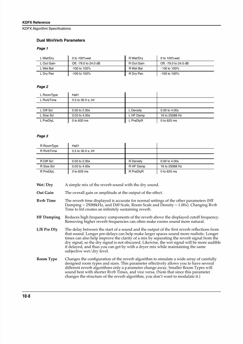
8/21/2019 MR_K2661
http://slidepdf.com/reader/full/mrk2661 90/499
10-8
KDFX Reference
KDFX Algorithm Specifications
Dual MiniVerb Parameters
Page 1
Page 2
Page 3
Wet/Dry A simple mix of the reverb sound with the dry sound.
Out Gain The overall gain or amplitude at the output of the effect.
Rvrb Time The reverb time displayed is accurate for normal settings of the other parameters (HFDamping = 25088kHz, and Diff Scale, Room Scale and Density = 1.00x). Changing RvrbTime to Inf creates an infinitely sustaining reverb.
HF Damping Reduces high frequency components of the reverb above the displayed cutoff frequency.Removing higher reverb frequencies can often make rooms sound more natural.
L/R Pre Dly The delay between the start of a sound and the output of the first reverb reflections fromthat sound. Longer pre-delays can help make larger spaces sound more realistic. Longertimes can also help improve the clarity of a mix by separating the reverb signal from thedry signal, so the dry signal is not obscured. Likewise, the wet signal will be more audibleif delayed, and thus you can get by with a dryer mix while maintaining the samesubjective wet/dry level.
Room Type Changes the configuration of the reverb algorithm to simulate a wide array of carefullydesigned room types and sizes. This parameter effectively allows you to have severaldifferent reverb algorithms only a parameter change away. Smaller Room Types willsound best with shorter Rvrb Times, and vice versa. (Note that since this parameterchanges the structure of the reverb algorithm, you don’t want to modulate it.)
L Wet/Dry 0 to 100%wet R Wet/Dry 0 to 100%wet
L Out Gain Off, -79.0 to 24.0 dB R Out Gain Off, -79.0 to 24.0 dB
L Wet Bal -100 to 100% R Wet Bal -100 to 100%
L Dry Pan -100 to 100% R Dry Pan -100 to 100%
L RoomType Hall1
L RvrbTime 0.5 to 30.0 s, Inf
L Diff Scl 0.00 to 2.00x L Density 0.00 to 4.00x
L Size Scl 0.00 to 4.00x L HF Damp 16 to 25088 Hz
L PreDlyL 0 to 620 ms L PreDlyR 0 to 620 ms
R RoomType Hall1
R RvrbTime 0.5 to 30.0 s, Inf
R Diff Scl 0.00 to 2.00x R Density 0.00 to 4.00x
R Size Scl 0.00 to 4.00x R HF Damp 16 to 25088 Hz
R PreDlyL 0 to 620 ms R PreDlyR 0 to 620 ms
8/21/2019 MR_K2661
http://slidepdf.com/reader/full/mrk2661 91/499
KDFX Reference
KDFX Algorithm Specifications
10-9
Diff Scale A multiplier which affects the diffusion of the reverb. At 1.00x, the diffusion will be thenormal, carefully adjusted amount for the current Room Type. Altering this parameterwill change the diffusion from the preset amount.
Size Scale A multiplier which changes the size of the current room. At 1.00x, the room will be thenormal, carefully tweaked size of the current Room Type. Altering this parameter willchange the size of the room, and thus will cause a subtle coloration of the reverb (since theroom’s dimensions are changing).
Density A multiplier which affects the density of the reverb. At 1.00x, the room density will be thenormal, carefully set amount for the current Room Type. Altering this parameter willchange the density of the reverb, which may color the room slightly.
Wet Bal In Dual MiniVerb, two mono signals (left and right) are fed into two separate stereoreverbs. If you center the wet balance (0%), the left and right outputs of the reverb will besent to the final output in equal amounts. This will add a sense of spaciousness
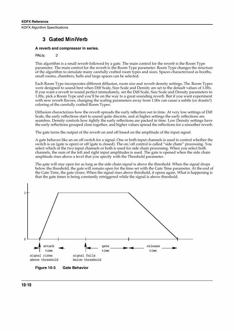
8/21/2019 MR_K2661
http://slidepdf.com/reader/full/mrk2661 92/499
10-10
KDFX Reference
KDFX Algorithm Specifications
3 Gated MiniVerb
A reverb and compressor in series.
PAUs: 2
This algorithm is a small reverb followed by a gate. The main control for the reverb is the Room Typeparameter. The main control for the reverb is the Room Type parameter. Room Type changes the structureof the algorithm to simulate many carefully crafted room types and sizes. Spaces characterized as booths,small rooms, chambers, halls and large spaces can be selected.
Each Room Type incorporates different diffusion, room size and reverb density settings. The Room Typeswere designed to sound best when Diff Scale, Size Scale and Density are set to the default values of 1.00x.If you want a reverb to sound perfect immediately, set the Diff Scale, Size Scale and Density parameters to1.00x, pick a Room Type and you’ll be on the way to a great sounding reverb. But if you want experimentwith new reverb flavors, changing the scaling parameters away from 1.00x can cause a subtle (or drastic!)coloring of the carefully crafted Room Types.
Diffusion characterizes how the reverb spreads the early reflection out in time. At very low settings of Diff
Scale, the early reflections start to sound quite discrete, and at higher settings the early reflections areseamless. Density controls how tightly the early reflections are packed in time. Low Density settings havethe early reflections grouped close together, and higher values spread the reflections for a smoother reverb.
The gate turns the output of the reverb on and off based on the amplitude of the input signal.
A gate behaves like an on off switch for a signal. One or both input channels is used to control whether theswitch is on (gate is open) or off (gate is closed). The on/off control is called “side chain” processing. Youselect which of the two input channels or both is used for side chain processing. When you select bothchannels, the sum of the left and right input amplitudes is used. The gate is opened when the side chainamplitude rises above a level that you specify with the Threshold parameter.
The gate will stay open for as long as the side chain signal is above the threshold. When the signal drops below the threshold, the gate will remain open for the time set with the Gate Time parameter. At the end of
the Gate Time, the gate closes. When the signal rises above threshold, it opens again. What is happening isthat the gate timer is being constantly retriggered while the signal is above threshold.
Figure 10-3 Gate Behavior
0
1
attack
time
gate
time
release
time
signal rises
above threshold
signal falls
below threshold
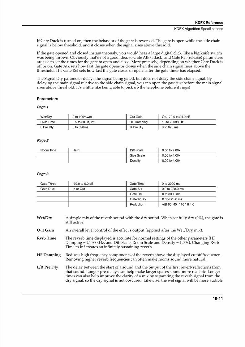
8/21/2019 MR_K2661
http://slidepdf.com/reader/full/mrk2661 93/499
KDFX Reference
KDFX Algorithm Specifications
10-11
If Gate Duck is turned on, then the behavior of the gate is reversed. The gate is open while the side chainsignal is below threshold, and it closes when the signal rises above thresold.
If the gate opened and closed instantaneously, you would hear a large digital click, like a big knife switchwas being thrown. Obviously that’s not a good idea, so Gate Atk (attack) and Gate Rel (release) parametersare use to set the times for the gate to open and close. More precisely, depending on whether Gate Duck isoff or on, Gate Atk sets how fast the gate opens or closes when the side chain signal rises above thethreshold. The Gate Rel sets how fast the gate closes or opens after the gate timer has elapsed.
The Signal Dly parameter delays the signal being gated, but does not delay the side chain signal. Bydelaying the main signal relative to the side chain signal, you can open the gate just before the main signalrises above threshold. It’s a little like being able to pick up the telephone before it rings!
Parameters
Page 1
Page 2
Page 3
Wet/Dry A simple mix of the reverb sound with the dry sound. When set fully dry (0%), the gate isstill active.
Out Gain An overall level control of the effect’s output (applied after the Wet/Dry mix).
Rvrb Time The reverb time displayed is accurate for normal settings of the other parameters (HF
Damping = 25088kHz, and Diff Scale, Room Scale and Density = 1.00x). Changing RvrbTime to Inf creates an infinitely sustaining reverb.
HF Damping Reduces high frequency components of the reverb above the displayed cutoff frequency.Removing higher reverb frequencies can often make rooms sound more natural.
L/R Pre Dly The delay between the start of a sound and the output of the first reverb reflections fromthat sound. Longer pre-delays can help make larger spaces sound more realistic. Longertimes can also help improve the clarity of a mix by separating the reverb signal from thedry signal, so the dry signal is not obscured. Likewise, the wet signal will be more audible
Wet/Dry 0 to 100%wet Out Gain Off, -79.0 to 24.0 dB
Rvrb Time 0.5 to 30.0s, Inf HF Damping 16 to 25088 Hz
L Pre Dly 0 to 620ms R Pre Dly 0 to 620 ms
Room Type Hall1 Diff Scale 0.00 to 2.00x
Size Scale 0.00 to 4.00x
Density 0.00 to 4.00x
Gate Thres -79.0 to 0.0 dB Gate Time 0 to 3000 ms
Gate Duck In or Out Gate Atk 0.0 to 228.0 ms
Gate Rel 0 to 3000 ms
GateSigDly 0.0 to 25.0 ms
Reduction -dB 60 40 * 16 * 8 4 0
8/21/2019 MR_K2661
http://slidepdf.com/reader/full/mrk2661 94/499
10-12
KDFX Reference
KDFX Algorithm Specifications
if delayed, and thus you can get by with a dryer mix while maintaining the samesubjective wet/dry level.
Room Type The configuration of the reverb algorithm to simulate a wide array of carefully designedroom types and sizes. This parameter effectively allows you to have several differentreverb algorithms only a parameter change away. Smaller Room Types will sound bestwith shorter Rvrb Times, and vice versa. (Note that since this parameter changes thestructure of the reverb algorithm, you may not modulate it.)
Diff Scale A multiplier which affects the diffusion of the reverb. At 1.00x, the diffusion will be thenormal, carefully adjusted amount for the current Room Type. Altering this parameterwill change the diffusion from the preset amount.
Size Scale A multiplier which changes the size of the current room. At 1.00x, the room will be thenormal, carefully tweaked size of the current Room Type. Altering this parameter willchange the size of the room, and thus will cause a subtle coloration of the reverb (since theroom’s dimensions are changing).
Density A multiplier which affects the density of the reverb. At 1.00x, the room density will be the
normal, carefully set amount for the current Room Type. Altering this parameter willchange the density of the reverb, which may color the room slightly.
Gate Thres The input signal level in dB required to open the gate (or close the gate if Gate Duck is on).
Gate Duck When set to “Off”, the gate opens when the signal rises above threshold and closes whenthe gate time expires. When set to “On”, the gate closes when the signal rises abovethreshold and opens when the gate time expires.
Gate Time The time in seconds that the gate will stay fully on after the signal envelope rises abovethreshold. The gate timer is started or restarted whenever the signal envelope rises abovethreshold. If Retrigger is On, the gate timer is continually reset while the side chain signalis above the threshold.
Gate Atk The attack time for the gate to ramp from closed to open (reverse if Gate Duck is on) after
the signal rises above threshold.
Gate Rel The release time for the gate to ramp from open to closed (reverse if Gate Duck is on) afterthe gate timer has elapsed.
Signal Dly The delay in milliseconds (ms) of the reverb signal relative to the side chain signal. Bydelaying the reverb signal, the gate can be opened before the reverb signal rises above thegating threshold.
8/21/2019 MR_K2661
http://slidepdf.com/reader/full/mrk2661 95/499
KDFX Reference
KDFX Algorithm Specifications
10-13
Algorithms 4–11: Classic / TQ / Diffuse / Omni Reverbs
4 Classic Place
5 Classic Verb6 TQ Place7 TQ Verb8 Diffuse Place9 Diffuse Verb
10 OmniPlace11 OmniVerb
Parameters
Absorption This controls the amount of refl
ective material that is in the space beingemulated, much like an acoustical absorption coef ficient. The lower the setting,the longer it will take for the sound to die away. A setting of 0% will cause aninfinite decay time.
Rvrb Time Adjusts the basic decay time of the late portion of the reverb.
LateRvbTim Adjusts the basic decay time of the late portion of the reverb after diffusion.
HF Damping This controls the amount of high frequency energy that is absorbed as thereverb decays. The values set the cutoff frequency of the 1 pole (6dB/oct) lopassfilter within the reverb feedback loop.
L Pre Dly, R Pre Dly These control the amount that each channel of the reverb is delayed relative tothe dry signal. Setting different lengths for both channels can de-correlate the
center portion of the reverb image and make it seem wider. This only affects thelate reverb in algorithms that have early reflections.
Lopass Controls the cutoff frequency of a 1 pole (6dB/oct) lopass filter at the output ofthe reverb. This only affects the late reverb in algorithms that have earlyreflections.
EarRef Lvl Adjusts the mix level of the early reflection portion of algorithms offering earlyreflections.
Late Lvl Adjusts the mix level of the late reverb portion of algorithms offering earlyreflections.
Room Type This parameter selects the basic type of reverb being emulated, and should beyour starting point when creating your own reverb presets. Due to the inherentcomplexity of reverb algorithms and the sheer number of variables responsiblefor their character, the Room Type parameter provides condensed presetcollections of these variables. Each Room Type preset has been painstakinglyselected by Kurzweil engineers to provide the best sounding collection ofmutually complementary variables modelling an assortment of reverb families.When a room type is selected, an entire incorporated set of delay lengths anddiffusion settings are established within the algorithm. By using the Size Scale,DiffAmtScl, DiffLenScl, and Inj Spread parameters, you may scale individualelements away from their preset value. When set to 1.00x, each of these
8/21/2019 MR_K2661
http://slidepdf.com/reader/full/mrk2661 96/499
10-14
KDFX Reference
KDFX Algorithm Specifications
elements are accurately representing their preset values determined by thecurrent Room Type.
Room Types with similar names in different reverb algorithms do not sound thesame. For example, Hall1 in Diffuse Verb does not sound the same as Hall1 inTQ Verb.
Size Scale This parameter scales the inherent size of the reverb chosen by Room Type. Fora true representation of the selected Room Type size, set this to 1.00x. Scalingthe size below this will create smaller spaces, while larger scale factors willcreate large spaces. See Room Type for more detailed information.
InfinDecay Found in “Verb” algorithms. When turned “On”, the reverb tail will decayindefinitely. When turned “Off”, the decay time is determined by the “RvrbTime” or “LateRvbTim” parameters.
LF Split Used in conjunction with LF Time. This controls the upper frequency limit ofthe low frequency decay time multiplier. Energy below this frequency willdecay faster or slower depending on the LF Time parameter.
LF Time Used in conjunction with LF Split. This modifies the decay time of the energy below the LF Split frequency. A setting of 1.00x will make low frequency energydecay at the rate determined by the decay time. Higher values will cause lowfrequency energy to decay slower, and lower values will cause it to decay morequickly.
TrebShlf F Adjusts the frequency of a high shelving filter at the output of the late reverb.
TrebShlf G Adjusts the gain of a high shelving filter at the output of the late reverb.
BassShlf F Adjusts the frequency of a low shelving filter at the output of the late reverb.
BassShlf G Adjusts the gain of a low shelving filter at the output of the late reverb.
DiffAmtScl Adjusts the amount of diffusion at the onset of the reverb. For a truerepresentation of the selected Room Type diffusion amount, set this to 1.00x.
DiffLenScl Adjusts the length of the diffusion at the onset of the reverb. For a truerepresentation of the selected Room Type diffusion length, set this to 1.00x.
DiffExtent Adjust the onset diffusion duration. Higher values create longer diffuse burstsat the onset of the reverb.
Diff Cross Adjusts the onset diffusion cross-coupling character. Although subtle, thisparameter bleeds left and right channels into each other during onset diffusion,and also in the body of the reverb. 0% setting will disable this. Increasing thisvalue in either the positive or negative direction will increase its affect.
Expanse Amount of late reverb energy biased toward the edges of the stereo image. A
setting of 0% will bias energy towards the center. Moving away from 0% will bias energy towards the sides. Positive and negative values will have a differentcharacter.
LFO Rate Adjusts the rate at which certain reverb delay lines move. See LFO Depth formore information.
LFO Depth Adjusts the detuning depth in cents caused by a moving reverb delay line.Moving delay lines can imitate voluminous flowing air currents and reduceunwanted artifacts like ringing and flutter when used properly. Depth settingsunder 1.5ct with LFO Rate settings under 1.00Hz are recommended for
8/21/2019 MR_K2661
http://slidepdf.com/reader/full/mrk2661 97/499
KDFX Reference
KDFX Algorithm Specifications
10-15
modeling real spaces. High depth settings can create chorusing qualities, whichwon’t be unsuitable for real acoustic spaces, but can nonetheless createinteresting effects. Instruments that have little if no inherent pitch fluctuation(like piano) are much more sensitive to this LFO than instruments that normallyhave a lot of vibrato (like voice) or non-pitched instruments (like snare drum).
Inj Build Used in conjunction with Inj Spread, this adjusts the envelope of the onset of thereverb. Specifically, it tapers the amplitudes of a series of delayed signalsinjected into the body of the reverb. Values above 0% will produce a faster build, while values below 0% will cause the build to be more gradual.
Inj Spread Used in conjunction with Inj Build, this scales the length of the series of delaysinjected into the body of the reverb. For a true representation of the selectedRoom Type injector spread, set this to 1.00x.
Inj LP This adjusts the cutoff frequency of a 1 pole (6dB/oct) lopass filter applied tothe signal being injected into the body of the reverb.
Inj Skew Adjusts the amount of delay applied to either the left or right channel of the
reverb injector. Positive values delay the right channel while negative valuesdelay the left channel.
E DiffAmt Adjusts the amount of diffusion applied to the early reflection network.
E DfLenScl Adjusts the length of diffusion applied to the early reflection network. This isinfluenced by E PreDlyL and E PreDlyR.
E Dly Scl Scales the delay lengths inherent in the early reflection network.
E Build Adjusts the envelope of the onset of the early reflections. Values above 0% willcreate a faster attack while values below 0% will create a slower attack.
E Fdbk Amt Adjusts the amount of the output of an early reflection portion that is fed backinto the input of the opposite channel in front of the early pre-delays. Overall, it
lengthens the decay rate of the early reflection network. Negative valuespolarity invert the feedback signal.
E HF Damp This adjusts the cutoff frequency of a 1 pole (6dB/oct) lopass filter applied tothe early reflection feedback signal.
E PreDlyL, E PreDlyR Adjusts how much the early reflections are delayed relative to the dry signal.These are independent of the late reverb predelay times, but will influence EDly Scl.
E Dly L, E Dly R Adjusts the left and right early reflection delays fed to the same outputchannels.
E Dly LX, E Dly RX Adjusts the left and right early reflection delays fed to the opposite outputchannels.
E DifDlyL, E DifDlyR Adjusts the diffusion delays of the diffusers on delay taps fed to the sameoutput channels.
E DifDlyLX, E DifDlyRX Adjusts the diffusion delays of the diffusers on delay taps fed to the oppositeoutput channels.
E X Blend Adjusts the balance between early reflection delay tap signals with diffusers fedto their same output channel, and those fed to opposite channels. 0% will onlyallow delay taps being fed to opposite output channels to be heard, while 100%allows only delay taps going to the same channels to be heard.
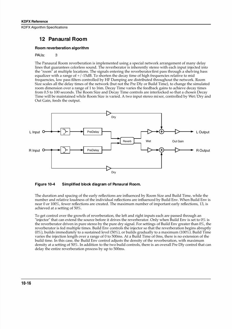
8/21/2019 MR_K2661
http://slidepdf.com/reader/full/mrk2661 98/499
10-16
KDFX Reference
KDFX Algorithm Specifications
12 Panaural Room
Room reverberation algorithm
PAUs: 3
The Panaural Room reverberation is implemented using a special network arrangement of many delaylines that guarantees colorless sound. The reverberator is inherently stereo with each input injected intothe "room" at multiple locations. The signals entering the reverberator first pass through a shelving bassequalizer with a range of +/-15dB. To shorten the decay time of high frequencies relative to midfrequencies, low pass filters controlled by HF Damping are distributed throughout the network. RoomSize scales all the delay times of the network (but not the Pre Dly or Build Time), to change the simulatedroom dimension over a range of 1 to 16m. Decay Time varies the feedback gains to achieve decay timesfrom 0.5 to 100 seconds. The Room Size and Decay Time controls are interlocked so that a chosen DecayTime will be maintained while Room Size is varied. A two input stereo mixer, controlled by Wet/Dry andOut Gain, feeds the output.
Figure 10-4 Simplified block diagram of Panaural Room.
The duration and spacing of the early reflections are influenced by Room Size and Build Time, while thenumber and relative loudness of the individual reflections are influenced by Build Env. When Build Env isnear 0 or 100%, fewer reflections are created. The maximum number of important early reflections, 13, isachieved at a setting of 50%.
To get control over the growth of reverberation, the left and right inputs each are passed through an"injector" that can extend the source before it drives the reverberator. Only when Build Env is set to 0% isthe reverberator driven in pure stereo by the pure dry signal. For settings of Build Env greater than 0%, thereverberator is fed multiple times. Build Env controls the injector so that the reverberation begins abruptly(0%), builds immediately to a sustained level (50%), or builds gradually to a maximum (100%). Build Timevaries the injection length over a range of 0 to 500ms. At a Build Time of 0ms, there is no extension of the build time. In this case, the Build Env control adjusts the density of the reverberation, with maximumdensity at a setting of 50%. In addition to the two build controls, there is an overall Pre Dly control that candelay the entire reverberation process by up to 500ms.
PreDelay
PreDelay
Reverb
Dry
Dry
Out Gain
L Output
R Output
L Input
R Input
Wet
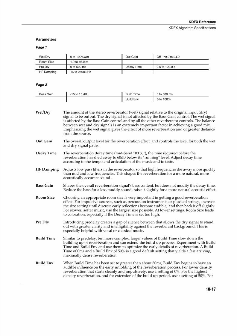
8/21/2019 MR_K2661
http://slidepdf.com/reader/full/mrk2661 99/499
KDFX Reference
KDFX Algorithm Specifications
10-17
Parameters
Page 1
Page 2
Wet/Dry The amount of the stereo reverberator (wet) signal relative to the original input (dry)
signal to be output. The dry signal is not affected by the Bass Gain control. The wet signalis affected by the Bass Gain control and by all the other reverberator controls. The balance between wet and dry signals is an extremely important factor in achieving a good mix.Emphasizing the wet signal gives the effect of more reverberation and of greater distancefrom the source.
Out Gain The overall output level for the reverberation effect, and controls the level for both the wetand dry signal paths.
Decay Time The reverberation decay time (mid-band "RT60"), the time required before thereverberation has died away to 60dB below its "running" level. Adjust decay timeaccording to the tempo and articulation of the music and to taste.
HF Damping Adjusts low pass filters in the reverberator so that high frequencies die away more quicklythan mid and low frequencies. This shapes the reverberation for a more natural, moreacoustically accurate sound.
Bass Gain Shapes the overall reverberation signal's bass content, but does not modify the decay time.Reduce the bass for a less muddy sound, raise it slightly for a more natural acoustic effect.
Room Size Choosing an appropriate room size is very important in getting a good reverberationeffect. For impulsive sources, such as percussion instruments or plucked strings, increasethe size setting until discrete early reflections become audible, and then back it off slightly.For slower, softer music, use the largest size possible. At lower settings, Room Size leadsto coloration, especially if the Decay Time is set too high.
Pre Dly Introducing predelay creates a gap of silence between that allows the dry signal to standout with greater clarity and intelligibility against the reverberant background. This isespecially helpful with vocal or classical music.
Build Time Similar to predelay, but more complex, larger values of Build Time slow down the building up of reverberation and can extend the build up process. Experiment with BuildTime and Build Env and use them to optimize the early details of reverberation. A BuildTime of 0ms and a Build Env of 50% is a good default setting that yields a fast arriving,maximally dense reverberation.
Build Env When Build Time has been set to greater than about 80ms, Build Env begins to have anaudible influence on the early unfolding of the reverberation process. For lower densityreverberation that starts cleanly and impulsively, use a setting of 0%. For the highestdensity reverberation, and for extension of the build up period, use a setting of 50%. For
Wet/Dry 0 to 100%wet Out Gain Off, -79.0 to 24.0
Room Size 1.0 to 16.0 m
Pre Dly 0 to 500 ms Decay Time 0.5 to 100.0 s
HF Damping 16 to 25088 Hz
Bass Gain -15 to 15 dB Build Time 0 to 500 ms
Build Env 0 to 100%
8/21/2019 MR_K2661
http://slidepdf.com/reader/full/mrk2661 100/499
10-18
KDFX Reference
KDFX Algorithm Specifications
an almost reverse reverberation, set Build Env to 100%. You can think of Build Env assetting the position of a see-saw. The left end of the see-saw represents the driving of thereverberation at the earliest time, the pivot point as driving the reverberation at mid-pointin the time sequence, and the right end as the last signal to drive the reverberator. Atsettings near 0%, the see-saw is tilted down on the right: the reverberation starts abruptlyand the drive drops with time. Near 50%, the see-saw is level and the reverberation isrepetitively fed during the entire build time. At settings near 100%, the see-saw is tilteddown on the left, so that the reverberation is hit softly at first, and then at increasing leveluntil the end of the build time.
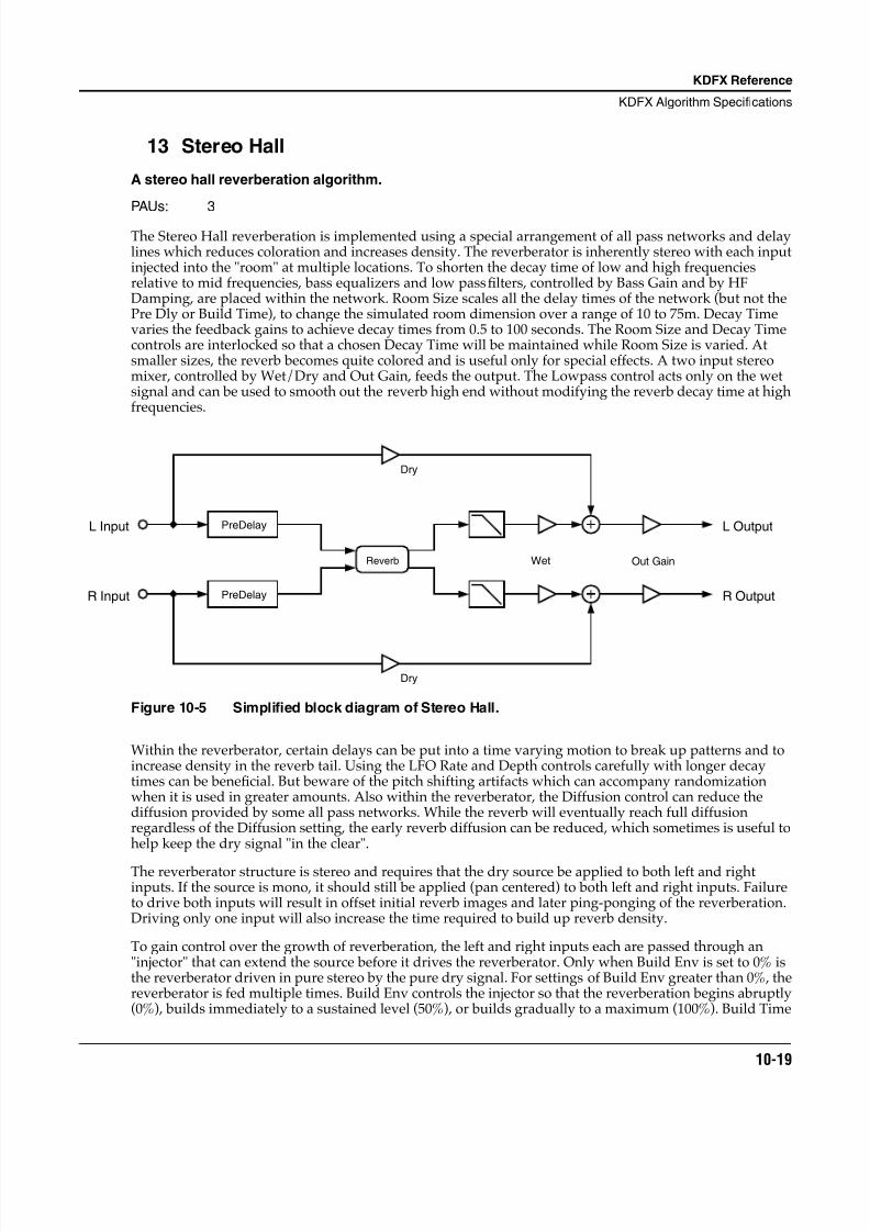
8/21/2019 MR_K2661
http://slidepdf.com/reader/full/mrk2661 101/499
KDFX Reference
KDFX Algorithm Specifications
10-19
13 Stereo Hall
A stereo hall reverberation algorithm.
PAUs: 3
The Stereo Hall reverberation is implemented using a special arrangement of all pass networks and delaylines which reduces coloration and increases density. The reverberator is inherently stereo with each inputinjected into the "room" at multiple locations. To shorten the decay time of low and high frequenciesrelative to mid frequencies, bass equalizers and low pass filters, controlled by Bass Gain and by HFDamping, are placed within the network. Room Size scales all the delay times of the network (but not thePre Dly or Build Time), to change the simulated room dimension over a range of 10 to 75m. Decay Timevaries the feedback gains to achieve decay times from 0.5 to 100 seconds. The Room Size and Decay Timecontrols are interlocked so that a chosen Decay Time will be maintained while Room Size is varied. Atsmaller sizes, the reverb becomes quite colored and is useful only for special effects. A two input stereomixer, controlled by Wet/Dry and Out Gain, feeds the output. The Lowpass control acts only on the wetsignal and can be used to smooth out the reverb high end without modifying the reverb decay time at highfrequencies.
Figure 10-5 Simplified block diagram of Stereo Hall.
Within the reverberator, certain delays can be put into a time varying motion to break up patterns and toincrease density in the reverb tail. Using the LFO Rate and Depth controls carefully with longer decaytimes can be beneficial. But beware of the pitch shifting artifacts which can accompany randomizationwhen it is used in greater amounts. Also within the reverberator, the Diffusion control can reduce thediffusion provided by some all pass networks. While the reverb will eventually reach full diffusionregardless of the Diffusion setting, the early reverb diffusion can be reduced, which sometimes is useful tohelp keep the dry signal "in the clear".
The reverberator structure is stereo and requires that the dry source be applied to both left and rightinputs. If the source is mono, it should still be applied (pan centered) to both left and right inputs. Failureto drive both inputs will result in offset initial reverb images and later ping-ponging of the reverberation.Driving only one input will also increase the time required to build up reverb density.
To gain control over the growth of reverberation, the left and right inputs each are passed through an"injector" that can extend the source before it drives the reverberator. Only when Build Env is set to 0% isthe reverberator driven in pure stereo by the pure dry signal. For settings of Build Env greater than 0%, thereverberator is fed multiple times. Build Env controls the injector so that the reverberation begins abruptly(0%), builds immediately to a sustained level (50%), or builds gradually to a maximum (100%). Build Time
L Input
R Input
PreDelay
PreDelay
Dry
Dry
Out GainWetReverb
L Output
R Output
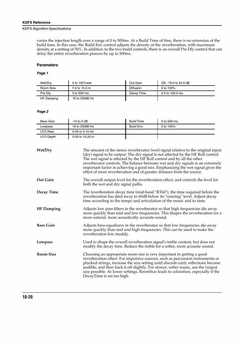
8/21/2019 MR_K2661
http://slidepdf.com/reader/full/mrk2661 102/499
10-20
KDFX Reference
KDFX Algorithm Specifications
varies the injection length over a range of 0 to 500ms. At a Build Time of 0ms, there is no extension of the build time. In this case, the Build Env control adjusts the density of the reverberation, with maximumdensity at a setting of 50%. In addition to the two build controls, there is an overall Pre Dly control that candelay the entire reverberation process by up to 500ms.
Parameters
Page 1
Page 2
Wet/Dry The amount of the stereo reverberator (wet) signal relative to the original input(dry) signal to be output. The dry signal is not affected by the HF Roll control.The wet signal is affected by the HF Roll control and by all the otherreverberator controls. The balance between wet and dry signals is an extremelyimportant factor in achieving a good mix. Emphasizing the wet signal gives theeffect of more reverberation and of greater distance from the source.
Out Gain The overall output level for the reverberation effect, and controls the level for both the wet and dry signal paths.
Decay Time The reverberation decay time (mid-band "RT60"), the time required before thereverberation has died away to 60dB below its "running" level. Adjust decaytime according to the tempo and articulation of the music and to taste.
HF Damping Adjusts low pass filters in the reverberator so that high frequencies die awaymore quickly than mid and low frequencies. This shapes the reverberation for amore natural, more acoustically accurate sound.
Bass Gain Adjusts bass equalizers in the reverberator so that low frequencies die awaymore quickly than mid and high frequencies. This can be used to make thereverberation less muddy.
Lowpass Used to shape the overall reverberation signal's treble content, but does notmodify the decay time. Reduce the treble for a softer, more acoustic sound.
Room Size Choosing an appropriate room size is very important in getting a goodreverberation effect. For impulsive sources, such as percussion instruments orplucked strings, increase the size setting until discrete early reflections becomeaudible, and then back it off slightly. For slower, softer music, use the largestsize possible. At lower settings, RoomSize leads to coloration, especially if theDecayTime is set too high.
Wet/Dry 0 to 100%wet Out Gain Off, -79.0 to 24.0 dB
Room Size 2.0 to 15.0 m Diffusion 0 to 100%
Pre Dly 0 to 500 ms Decay Time 0.5 to 100.0 ms
HF Damping 16 to 25088 Hz
Bass Gain -15 to 0 dB Build Time 0 to 500 ms
Lowpass 16 to 25088 Hz Build Env 0 to 100%
LFO Rate 0.00 to 5.10 Hz
LFO Depth 0.00 to 10.20 ct
8/21/2019 MR_K2661
http://slidepdf.com/reader/full/mrk2661 103/499
KDFX Reference
KDFX Algorithm Specifications
10-21
Pre Dly Introducing predelay creates a gap of silence between that allows the dry signalto stand out with greater clarity and intelligibility against the reverberant background. This is especially helpful with vocal or classical music.
Build Time Similar to predelay, but more complex, larger values of BuildTime slow downthe building up of reverberation and can extend the build up process.Experiment with BuildTime and BuildEnv and use them to optimize the earlydetails of reverberation. A BuildTime of 0ms and a BuildEnv of 0% is a gooddefault setting that yields fast arriving, natural reverberation.
Build Env When BuildTime has been set to greater than about 80ms, BuildEnv begins tohave an audible influence on the early unfolding of the reverberation process.For lower density reverberation that starts cleanly and impulsively, use asetting of 0%. For the highest density reverberation, and for extension of the build up period, use a setting of 50%. For an almost reverse reverberation, setBuildEnv to 100%. You can think of BuildEnv as setting the position of a see-saw. The left end of the see-saw represents the driving of the reverberation atthe earliest time, the pivot point as driving the reverberation at mid-point in thetime sequence, and the right end as the last signal to drive the reverberator. At
settings near 0%, the see-saw is tilted down on the right: the reverberation startsabruptly and the drive drops with time. Near 50%, the see-saw is level and thereverberation is repetitively fed during the entire build time. At settings near100%, the see-saw is tilted down on the left, so that the reverberation is hit softlyat first, and then at increasing level until the end of the build time.
LFO Rate and Depth Within the reverberator, the certain delay values can be put into a time varyingmotion to break up patterns and to increase density in the reverb tail. Using theLFO Rate and Depth controls carefully with longer decay times can be beneficial. But beware of the pitch shifting artifacts which can accompanyrandomization when it is used in greater amounts.
Diffusion Within the reverberator, the Diffusion control can reduce the diffusion providedsome of the all pass networks. While the reverb will eventually reach full
diffusion regardless of the Diffusion setting, the early reverb diffusion can bereduced, which sometimes is useful to help keep the dry signal "in the clear."
8/21/2019 MR_K2661
http://slidepdf.com/reader/full/mrk2661 104/499
10-22
KDFX Reference
KDFX Algorithm Specifications
14 Grand Plate
A plate reverberation algorithm.
PAUs: 3
This algorithm emulates an EMT 140 steel plate reverberator. Plate reverberators were manufacturedduring the 1950's, 1960's, 1970's, and perhaps into the 1980's. By the end of the 1980's, they had beensupplanted in the marketplace by digital reverbertors, which first appeared in 1976. While a handful ofcompanies made plate reverberators, EMT (Germany) was the best known and most popular.
A plate reverberator is generally quite heavy and large, perhaps 4 feet high by 7 feet long and a foot thick.They were only slightly adjustable, with controls for high frequency damping and decay time. Some werestereo in, stereo out, others mono in, mono out.
A plate reverb begins with a sheet of plate steel suspended by its edges, leaving the plate free to vibrate. Atone (or two) points on the plate, an electromagnetic driver (sort of a small loudspeaker without a cone) isarranged to couple the dry signal into the plate, sending out sound vibrations into the plate in alldirections. At one or two other locations, a pickup is placed, sort of like a dynamic microphone whose
diaphragm is the plate itself, to pick up the reverberation.
Since the sound waves travel very rapidly in steel (faster than they do in air), and since the dimensions ofthe plate are not large, the sound quickly reaches the plate edges and reflects from them. This results in avery rapid build up of the reverberation, essentially free of early reflections and with no distinguishablegap before the onset of reverb.
Plates offered a wonderful sound of their own, easily distinguished from other reverberators in the pre-digital reverb era, such as springs or actual "echo" chambers. Plates were bright and diffused (built upecho density) rapidly. Curiously, when we listen to a vintage plate today, we find that the much vaunted brightness is nothing like what we can accomplish digitally; we actually have to deliberately reduce the brightness of a plate emulation to match the sound of a real plate. Similarly, we find that we must throttle back on the low frequency content as well.
The algorithm developed for Grand Plate was carefully crafted for rapid diffusion, low coloration,freedom from discrete early reflections, and "brightness." We also added some controls that were neverpresent in real plates: size, pre delay of up to 500ms, LF damping, low pass roll off, and bass roll off.Furthermore, we allow a wider range of decay time adjustment than a conventional plate. Once thealgorithm was complete, we tuned it by presenting the original EMT reverb on one channel and the GrandPlate emulation on the other. A lengthy and careful tuning of Grand Plate (tuning at the micro detail levelof each delay and gain in the algorithm) was carried out until the stereo spread of this reverb was matchedin all the time periods--early, middle, and late.
The heart of this reverb is the plate simulation network, with its two inputs and two outputs. It is a fullstereo reverberation network, which means that the left and right inputs get slightly different treatment inthe reverberator. This yields a richer, more natural stereo image from stereo sources. If you have a monosource, assign it to both inputs for best results.
The incoming left source is passed through predelay, low pass (Lowpass), and bass shelf (Bass Gain) blocks. The right source is treated similarly.
There are low pass filters (HF Damping) and high pass filters (LF Damping) embedded in the platesimulation network to modify the decay times. The reverb network also accomodates the Room Size andDecay Time controls.
An output mixer assembles dry and wet signals.
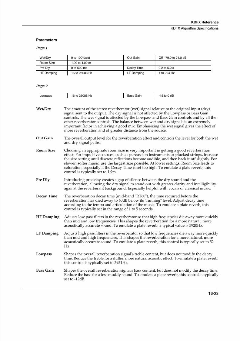
8/21/2019 MR_K2661
http://slidepdf.com/reader/full/mrk2661 105/499
KDFX Reference
KDFX Algorithm Specifications
10-23
Parameters
Page 1
Page 2
Wet/Dry The amount of the stereo reverberator (wet) signal relative to the original input (dry)signal sent to the output. The dry signal is not affected by the Lowpass or Bass Gain
controls. The wet signal is affected by the Lowpass and Bass Gain controls and by all theother reverberator controls. The balance between wet and dry signals is an extremelyimportant factor in achieving a good mix. Emphasizing the wet signal gives the effect ofmore reverberation and of greater distance from the source.
Out Gain The overall output level for the reverberation effect and controls the level for both the wetand dry signal paths.
Room Size Choosing an appropriate room size is very important in getting a good reverberationeffect. For impulsive sources, such as percussion instruments or plucked strings, increasethe size setting until discrete reflections become audible, and then back it off slightly. Forslower, softer music, use the largest size possible. At lower settings, Room Size leads tocoloration, especially if the Decay Time is set too high. To emulate a plate reverb, thiscontrol is typically set to 1.9m.
Pre Dly Introducing predelay creates a gap of silence between the dry sound and thereverberation, allowing the dry signal to stand out with greater clarity and intelligibilityagainst the reverberant background. Especially helpful with vocals or classical music.
Decay Time The reverberation decay time (mid-band "RT60"), the time required before thereverberation has died away to 60dB below its "running" level. Adjust decay timeaccording to the tempo and articulation of the music. To emulate a plate reverb, thiscontrol is typically set in the range of 1 to 5 seconds.
HF Damping Adjusts low pass filters in the reverberator so that high frequencies die away more quicklythan mid and low frequencies. This shapes the reverberation for a more natural, moreacoustically accurate sound. To emulate a plate reverb, a typical value is 5920Hz.
LF Damping Adjusts high pass filters in the reverberator so that low frequencies die away more quickly
than mid and high frequencies. This shapes the reverberation for a more natural, moreacoustically accurate sound. To emulate a plate reverb, this control is typically set to 52Hz.
Lowpass Shapes the overall reverberation signal's treble content, but does not modify the decaytime. Reduce the treble for a duller, more natural acoustic effect. To emulate a plate reverb,this control is typically set to 3951Hz.
Bass Gain Shapes the overall reverberation signal's bass content, but does not modify the decay time.Reduce the bass for a less muddy sound. To emulate a plate reverb, this control is typicallyset to -12dB.
Wet/Dry 0 to 100%wet Out Gain Off, -79.0 to 24.0 dB
Room Size 1.00 to 4.00 m
Pre Dly 0 to 500 ms Decay Time 0.2 to 5.0 s
HF Damping 16 to 25088 Hz LF Damping 1 to 294 Hz
Lowpass 16 to 25088 Hz Bass Gain -15 to 0 dB
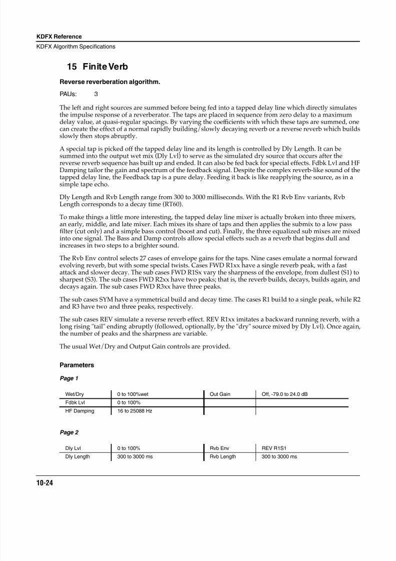
8/21/2019 MR_K2661
http://slidepdf.com/reader/full/mrk2661 106/499
10-24
KDFX Reference
KDFX Algorithm Specifications
15 Finite Verb
Reverse reverberation algorithm.
PAUs: 3
The left and right sources are summed before being fed into a tapped delay line which directly simulatesthe impulse response of a reverberator. The taps are placed in sequence from zero delay to a maximumdelay value, at quasi-regular spacings. By varying the coef ficients with which these taps are summed, onecan create the effect of a normal rapidly building/slowly decaying reverb or a reverse reverb which buildsslowly then stops abruptly.
A special tap is picked off the tapped delay line and its length is controlled by Dly Length. It can besummed into the output wet mix (Dly Lvl) to serve as the simulated dry source that occurs after thereverse reverb sequence has built up and ended. It can also be fed back for special effects. Fdbk Lvl and HFDamping tailor the gain and spectrum of the feedback signal. Despite the complex reverb-like sound of thetapped delay line, the Feedback tap is a pure delay. Feeding it back is like reapplying the source, as in asimple tape echo.
Dly Length and Rvb Length range from 300 to 3000 milliseconds. With the R1 Rvb Env variants, RvbLength corresponds to a decay time (RT60).
To make things a little more interesting, the tapped delay line mixer is actually broken into three mixers,an early, middle, and late mixer. Each mixes its share of taps and then applies the submix to a low passfilter (cut only) and a simple bass control (boost and cut). Finally, the three equalized sub mixes are mixedinto one signal. The Bass and Damp controls allow special effects such as a reverb that begins dull andincreases in two steps to a brighter sound.
The Rvb Env control selects 27 cases of envelope gains for the taps. Nine cases emulate a normal forwardevolving reverb, but with some special twists. Cases FWD R1xx have a single reverb peak, with a fastattack and slower decay. The sub cases FWD R1Sx vary the sharpness of the envelope, from dullest (S1) tosharpest (S3). The sub cases FWD R2xx have two peaks; that is, the reverb builds, decays, builds again, anddecays again. The sub cases FWD R3xx have three peaks.
The sub cases SYM have a symmetrical build and decay time. The cases R1 build to a single peak, while R2and R3 have two and three peaks, respectively.
The sub cases REV simulate a reverse reverb effect. REV R1xx imitates a backward running reverb, with along rising "tail" ending abruptly (followed, optionally, by the "dry" source mixed by Dly Lvl). Once again,the number of peaks and the sharpness are variable.
The usual Wet/Dry and Output Gain controls are provided.
Parameters
Page 1
Page 2
Wet/Dry 0 to 100%wet Out Gain Off, -79.0 to 24.0 dB
Fdbk Lvl 0 to 100%
HF Damping 16 to 25088 Hz
Dly Lvl 0 to 100% Rvb Env REV R1S1
Dly Length 300 to 3000 ms Rvb Length 300 to 3000 ms
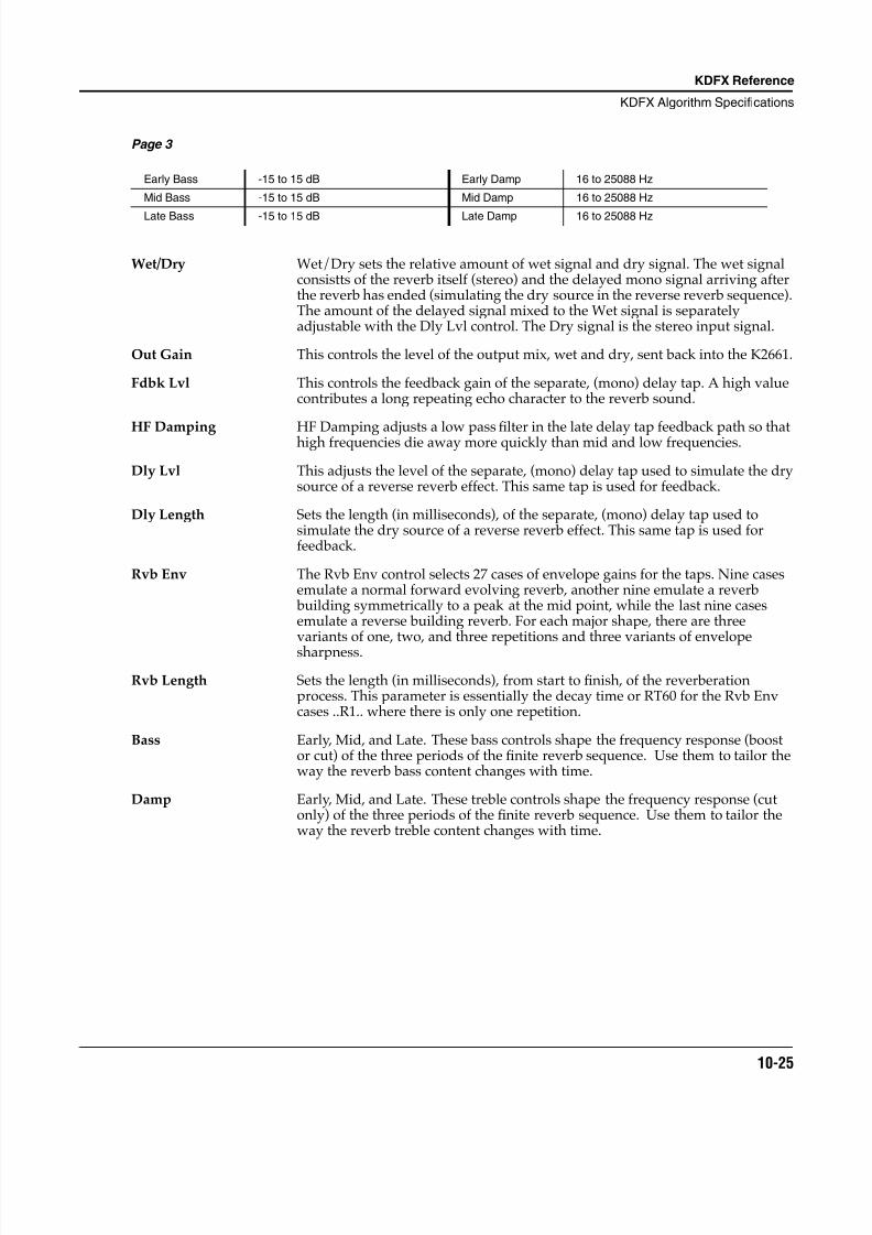
8/21/2019 MR_K2661
http://slidepdf.com/reader/full/mrk2661 107/499
KDFX Reference
KDFX Algorithm Specifications
10-25
Page 3
Wet/Dry Wet/Dry sets the relative amount of wet signal and dry signal. The wet signalconsistts of the reverb itself (stereo) and the delayed mono signal arriving afterthe reverb has ended (simulating the dry source in the reverse reverb sequence).The amount of the delayed signal mixed to the Wet signal is separatelyadjustable with the Dly Lvl control. The Dry signal is the stereo input signal.
Out Gain This controls the level of the output mix, wet and dry, sent back into the K2661.
Fdbk Lvl This controls the feedback gain of the separate, (mono) delay tap. A high valuecontributes a long repeating echo character to the reverb sound.
HF Damping HF Damping adjusts a low passfi
lter in the late delay tap feedback path so thathigh frequencies die away more quickly than mid and low frequencies.
Dly Lvl This adjusts the level of the separate, (mono) delay tap used to simulate the drysource of a reverse reverb effect. This same tap is used for feedback.
Dly Length Sets the length (in milliseconds), of the separate, (mono) delay tap used tosimulate the dry source of a reverse reverb effect. This same tap is used forfeedback.
Rvb Env The Rvb Env control selects 27 cases of envelope gains for the taps. Nine casesemulate a normal forward evolving reverb, another nine emulate a reverb building symmetrically to a peak at the mid point, while the last nine casesemulate a reverse building reverb. For each major shape, there are threevariants of one, two, and three repetitions and three variants of envelope
sharpness.
Rvb Length Sets the length (in milliseconds), from start to finish, of the reverberationprocess. This parameter is essentially the decay time or RT60 for the Rvb Envcases ..R1.. where there is only one repetition.
Bass Early, Mid, and Late. These bass controls shape the frequency response (boostor cut) of the three periods of the finite reverb sequence. Use them to tailor theway the reverb bass content changes with time.
Damp Early, Mid, and Late. These treble controls shape the frequency response (cutonly) of the three periods of the finite reverb sequence. Use them to tailor theway the reverb treble content changes with time.
Early Bass -15 to 15 dB Early Damp 16 to 25088 Hz
Mid Bass -15 to 15 dB Mid Damp 16 to 25088 Hz
Late Bass -15 to 15 dB Late Damp 16 to 25088 Hz
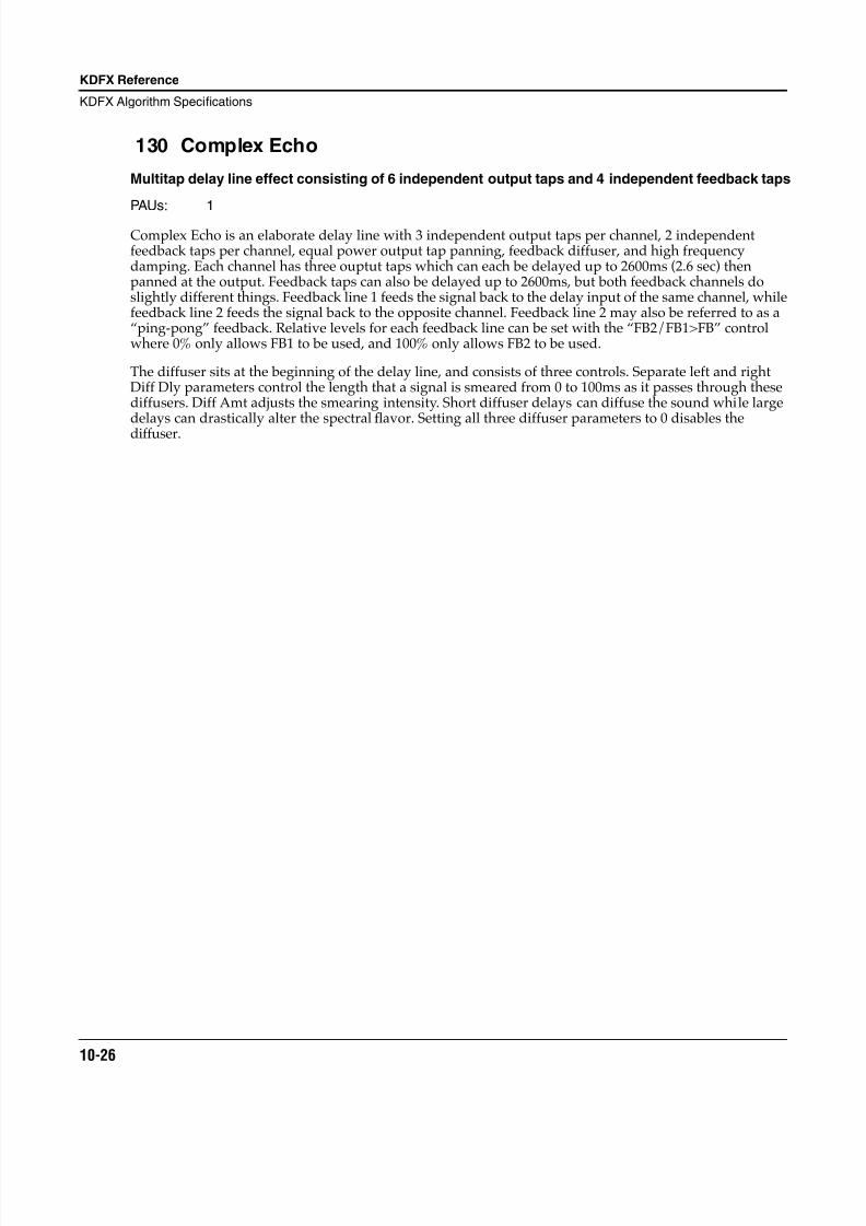
8/21/2019 MR_K2661
http://slidepdf.com/reader/full/mrk2661 108/499
10-26
KDFX Reference
KDFX Algorithm Specifications
130 Complex Echo
Multitap delay line effect consisting of 6 independent output taps and 4 independent feedback taps
PAUs: 1
Complex Echo is an elaborate delay line with 3 independent output taps per channel, 2 independentfeedback taps per channel, equal power output tap panning, feedback diffuser, and high frequencydamping. Each channel has three ouptut taps which can each be delayed up to 2600ms (2.6 sec) thenpanned at the output. Feedback taps can also be delayed up to 2600ms, but both feedback channels doslightly different things. Feedback line 1 feeds the signal back to the delay input of the same channel, whilefeedback line 2 feeds the signal back to the opposite channel. Feedback line 2 may also be referred to as a“ping-pong” feedback. Relative levels for each feedback line can be set with the “FB2/FB1>FB” controlwhere 0% only allows FB1 to be used, and 100% only allows FB2 to be used.
The diffuser sits at the beginning of the delay line, and consists of three controls. Separate left and rightDiff Dly parameters control the length that a signal is smeared from 0 to 100ms as it passes through thesediffusers. Diff Amt adjusts the smearing intensity. Short diffuser delays can diffuse the sound while largedelays can drastically alter the spectral flavor. Setting all three diffuser parameters to 0 disables thediffuser.
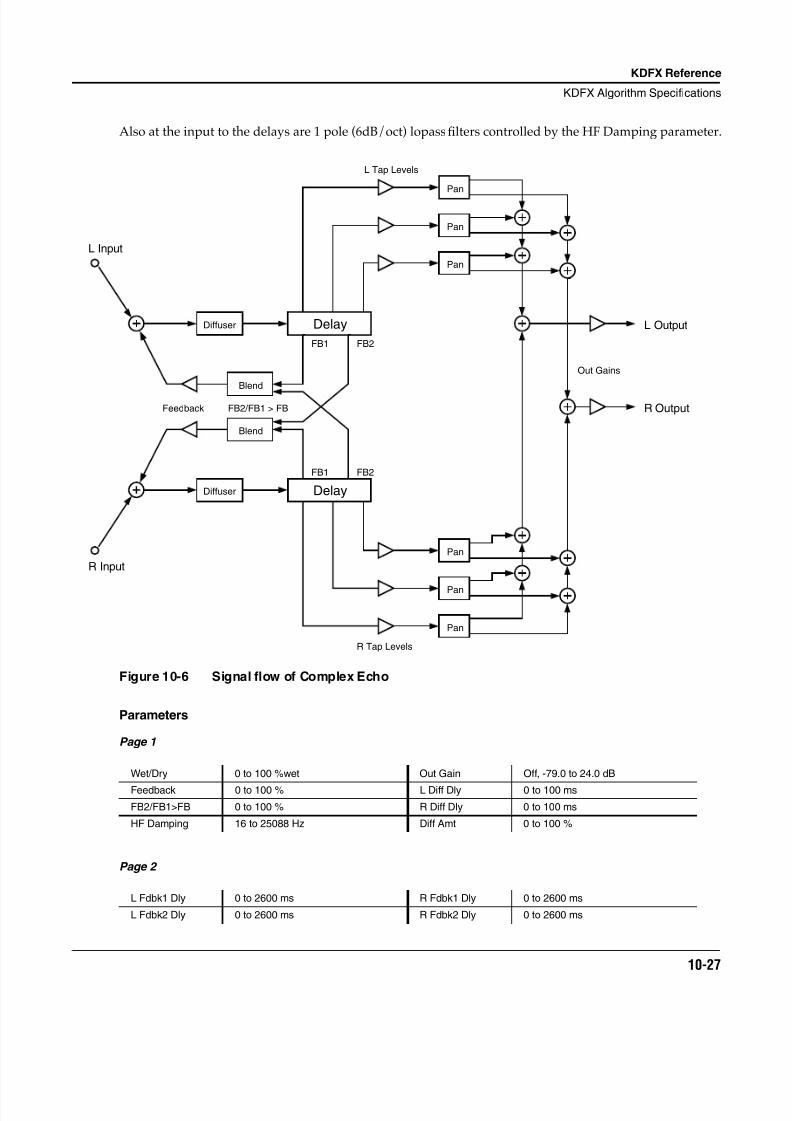
8/21/2019 MR_K2661
http://slidepdf.com/reader/full/mrk2661 109/499
KDFX Reference
KDFX Algorithm Specifications
10-27
Also at the input to the delays are 1 pole (6dB/oct) lopass filters controlled by the HF Damping parameter.
Figure 10-6 Signal flow of Complex Echo
Parameters
Page 1
Page 2
Wet/Dry 0 to 100 %wet Out Gain Off, -79.0 to 24.0 dB
Feedback 0 to 100 % L Diff Dly 0 to 100 ms
FB2/FB1>FB 0 to 100 % R Diff Dly 0 to 100 ms
HF Damping 16 to 25088 Hz Diff Amt 0 to 100 %
L Fdbk1 Dly 0 to 2600 ms R Fdbk1 Dly 0 to 2600 ms
L Fdbk2 Dly 0 to 2600 ms R Fdbk2 Dly 0 to 2600 ms
Delay
Pan
Pan
Pan
Pan
Pan
Pan
Delay
L Input
R Input
L Output
R OutputFeedback FB2/FB1 > FB
FB1 FB2
FB2FB1
L Tap Levels
R Tap Levels
Out Gains
Diffuser
Diffuser
Blend
Blend
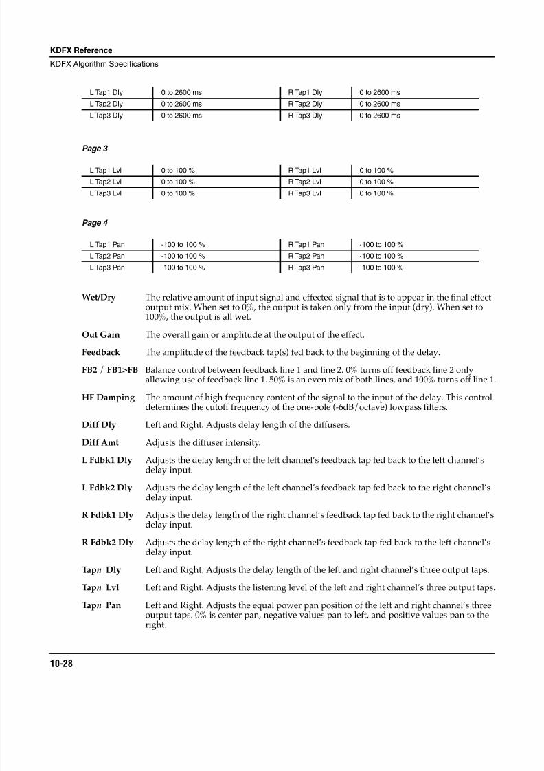
8/21/2019 MR_K2661
http://slidepdf.com/reader/full/mrk2661 110/499
10-28
KDFX Reference
KDFX Algorithm Specifications
Page 3
Page 4
Wet/Dry The relative amount of input signal and effected signal that is to appear in the final effectoutput mix. When set to 0%, the output is taken only from the input (dry). When set to100%, the output is all wet.
Out Gain The overall gain or amplitude at the output of the effect.
Feedback The amplitude of the feedback tap(s) fed back to the beginning of the delay.
FB2 / FB1>FB Balance control between feedback line 1 and line 2. 0% turns off feedback line 2 onlyallowing use of feedback line 1. 50% is an even mix of both lines, and 100% turns off line 1.
HF Damping The amount of high frequency content of the signal to the input of the delay. This control
determines the cutoff frequency of the one-pole (-6dB/octave) lowpass filters.
Diff Dly Left and Right. Adjusts delay length of the diffusers.
Diff Amt Adjusts the diffuser intensity.
L Fdbk1 Dly Adjusts the delay length of the left channel’s feedback tap fed back to the left channel’sdelay input.
L Fdbk2 Dly Adjusts the delay length of the left channel’s feedback tap fed back to the right channel’sdelay input.
R Fdbk1 Dly Adjusts the delay length of the right channel’s feedback tap fed back to the right channel’sdelay input.
R Fdbk2 Dly Adjusts the delay length of the right channel’s feedback tap fed back to the left channel’sdelay input.
Tapn Dly Left and Right. Adjusts the delay length of the left and right channel’s three output taps.
Tapn Lvl Left and Right. Adjusts the listening level of the left and right channel’s three output taps.
Tapn Pan Left and Right. Adjusts the equal power pan position of the left and right channel’s threeoutput taps. 0% is center pan, negative values pan to left, and positive values pan to theright.
L Tap1 Dly 0 to 2600 ms R Tap1 Dly 0 to 2600 ms
L Tap2 Dly 0 to 2600 ms R Tap2 Dly 0 to 2600 ms
L Tap3 Dly 0 to 2600 ms R Tap3 Dly 0 to 2600 ms
L Tap1 Lvl 0 to 100 % R Tap1 Lvl 0 to 100 %
L Tap2 Lvl 0 to 100 % R Tap2 Lvl 0 to 100 %
L Tap3 Lvl 0 to 100 % R Tap3 Lvl 0 to 100 %
L Tap1 Pan -100 to 100 % R Tap1 Pan -100 to 100 %
L Tap2 Pan -100 to 100 % R Tap2 Pan -100 to 100 %
L Tap3 Pan -100 to 100 % R Tap3 Pan -100 to 100 %
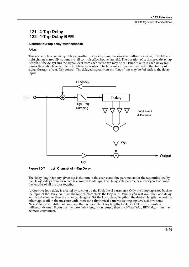
8/21/2019 MR_K2661
http://slidepdf.com/reader/full/mrk2661 111/499
KDFX Reference
KDFX Algorithm Specifications
10-29
131 4-Tap Delay132 4-Tap Delay BPM
A stereo four tap delay with feedback
PAUs: 1
This is a simple stereo 4 tap delay algorithm with delay lengths defined in milliseconds (ms). The left andright channels are fully symmetric (all controls affect both channels). The duration of each stereo delay tap(length of the delay) and the signal level from each stereo tap may be set. Prior to output each delay tappasses through a level and left-right balance control. The taps are summed and added to the dry inputsignal through a Wet/Dry control. The delayed signal from the “Loop” tap may be fed back to the delayinput.
Figure 10-7 Left Channel of 4-Tap Delay
The delay length for any given tap is the sum of the coarse and fine parameters for the tap multiplied bythe DelayScale parameter which is common to all taps. The DelayScale parameter allows you to changethe lengths of all the taps together.
A repetitive loop delay is created by turning up the Fdbk Level parameter. Only the Loop tap is fed back tothe input of the delay, so this is the tap which controls the loop rate. Usually you will want the Loop delaylength to be longer than the other tap lengths. Set the Loop delay length to the desired length then set theother taps to fill in the measure with interesting rhythmical patterns. Setting tap levels allows some“beats” to receive different emphasis than others. The delay lengths for 4-Tap Delay are in units ofmilliseconds (ms). If you want to base delay lengths on tempo, then the 4-Tap Delay BPM algorithm may be more convenient.
Tap Levels
& Balance
Wet
Output
Dry
Input
Feedback
Delay
High Freq
Damping
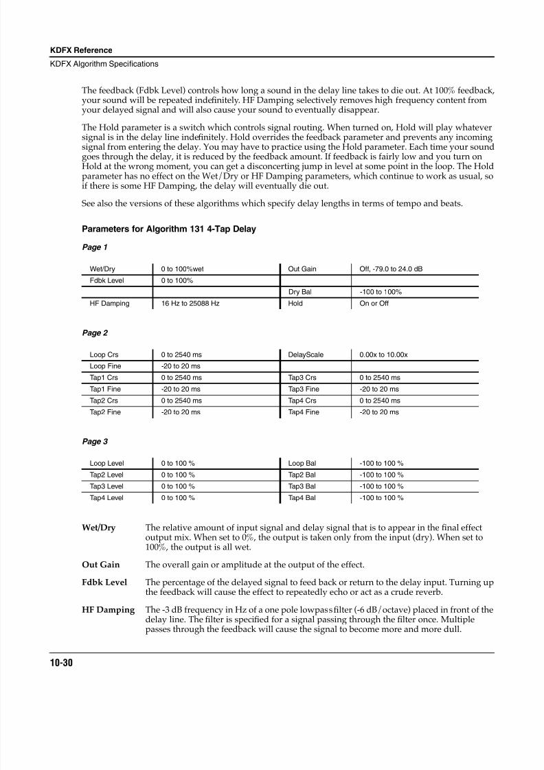
8/21/2019 MR_K2661
http://slidepdf.com/reader/full/mrk2661 112/499
10-30
KDFX Reference
KDFX Algorithm Specifications
The feedback (Fdbk Level) controls how long a sound in the delay line takes to die out. At 100% feedback,your sound will be repeated indefinitely. HF Damping selectively removes high frequency content fromyour delayed signal and will also cause your sound to eventually disappear.
The Hold parameter is a switch which controls signal routing. When turned on, Hold will play whateversignal is in the delay line indefinitely. Hold overrides the feedback parameter and prevents any incomingsignal from entering the delay. You may have to practice using the Hold parameter. Each time your soundgoes through the delay, it is reduced by the feedback amount. If feedback is fairly low and you turn onHold at the wrong moment, you can get a disconcerting jump in level at some point in the loop. The Holdparameter has no effect on the Wet/Dry or HF Damping parameters, which continue to work as usual, soif there is some HF Damping, the delay will eventually die out.
See also the versions of these algorithms which specify delay lengths in terms of tempo and beats.
Parameters for Algorithm 131 4-Tap Delay
Page 1
Page 2
Page 3
Wet/Dry The relative amount of input signal and delay signal that is to appear in the final effect
output mix. When set to 0%, the output is taken only from the input (dry). When set to100%, the output is all wet.
Out Gain The overall gain or amplitude at the output of the effect.
Fdbk Level The percentage of the delayed signal to feed back or return to the delay input. Turning upthe feedback will cause the effect to repeatedly echo or act as a crude reverb.
HF Damping The -3 dB frequency in Hz of a one pole lowpass filter (-6 dB/octave) placed in front of thedelay line. The filter is specified for a signal passing through the filter once. Multiplepasses through the feedback will cause the signal to become more and more dull.
Wet/Dry 0 to 100%wet Out Gain Off, -79.0 to 24.0 dBFdbk Level 0 to 100%
Dry Bal -100 to 100%
HF Damping 16 Hz to 25088 Hz Hold On or Off
Loop Crs 0 to 2540 ms DelayScale 0.00x to 10.00x
Loop Fine -20 to 20 ms
Tap1 Crs 0 to 2540 ms Tap3 Crs 0 to 2540 ms
Tap1 Fine -20 to 20 ms Tap3 Fine -20 to 20 ms
Tap2 Crs 0 to 2540 ms Tap4 Crs 0 to 2540 ms
Tap2 Fine -20 to 20 ms Tap4 Fine -20 to 20 ms
Loop Level 0 to 100 % Loop Bal -100 to 100 %
Tap2 Level 0 to 100 % Tap2 Bal -100 to 100 %
Tap3 Level 0 to 100 % Tap3 Bal -100 to 100 %
Tap4 Level 0 to 100 % Tap4 Bal -100 to 100 %
8/21/2019 MR_K2661
http://slidepdf.com/reader/full/mrk2661 113/499
KDFX Reference
KDFX Algorithm Specifications
10-31
Dry Bal The left-right balance of the dry signal. A setting of -100% allows only the left dry signal topass to the left output, while a setting of 100% lets only the right dry signal pass to theright output. At 0%, equal amounts of the left and right dry signals pass to their respectiveoutputs.
Hold A switch which when turned on, locks any signal currently in the delay to play until Holdis turned off. When Hold is on, no signal can enter the delay and Feedback is set to 100% behind the scenes. Hold does not affect the HF Damping or Wet/Dry mix.
Loop Crs The coarse delay length of the Loop tap. If the feedback is turned up, this parameter setsthe repeating delay loop length. The resolution of the coarse adjust is 20 milliseconds, butfiner resolution can be obtained using the Loop Fine parameter. The maximum delaylength is 2.55 seconds (2550ms) for the 4-Tap Delay.
Loop Fine A fine adjustment to the Loop tap delay length. The delay resolution is 0.2 milliseconds(ms). Loop Fine is added to Loop Crs (coarse) to get the actual delay length.
Tapn Crs The coarse delay lengths of the output taps (n = 1...4). The resolution of the coarse adjustis 20 milliseconds, but finer resolution can be obtained using the Tapn Fine parameters.
The maximum delay length is 2.55 seconds (2550ms) for the 4-Tap Delay.Tapn Fine A fine adjustment to the output tap delay lengths (n = 1...4). The delay resolution is 0.2
milliseconds (ms). Tapn Fine is added to Tapn Crs (coarse) to get actual delay lengths.
Tapn Level The amount of signal from each of the taps (n = 1...4) which get sent to the output. Withthe Loop Lvl control, you can give different amounts of emphasis to various taps in theloop.
Tapn Bal The left-right balance of each of the stereo taps (n = 1...4). A setting of -100% allows onlythe left tap to pass to the left output, while a setting of 100% lets only the right tap pass tothe right output. At 0%, equal amounts of the left and right taps pass to their respectiveoutputs.
Algorithm 132 4-Tap Delay BPMIn this Algorithm, the delay length for any given tap is determined by the tempo, expressed in beats perminute (BPM), and the delay length of the tap expressed in beats (bts). The tempo alters all tap lengthstogether. With the tempo in beats per minute and delay lengths in beats, you can calculate the length of adelay in seconds as beats/tempo * 60 (sec/min). IMPORTANT NOTE: KDFX has a limited amount ofdelay memory available (over 2.5 seconds for 4-Tap BPM). When slow tempos and/or long lengths arespecified, you may run out of delay memory, at which point the delay length will be cut in half. When youslow down the tempo, you may find the delays suddently getting shorter.
A repetitive loop delay is created by turning up the feedback parameter (Fdbk Level). Only the Loop tap isfed back to the input of the delay, so this is the tap which controls the loop rate. Usually you will want theLoop tap (LoopLength parameter) to be longer than the other tap lengths. To repeat a pattern on a 4/4measure (4 beats per measure) simply set LoopLength to 4 bts. The output taps can then be used to fill inthe measure with interesting rhythmical patterns. Setting tap levels allows some “beats” to receivedifferent emphasis than others.
8/21/2019 MR_K2661
http://slidepdf.com/reader/full/mrk2661 114/499
10-32
KDFX Reference
KDFX Algorithm Specifications
Parameters
Page 1
Page 2
Page 3
Tempo Basis for the delay lengths, as referenced to a musical tempo in bpm (beats per minute).When this parameter is set to “System”, the tempo is locked to the internal sequencertempo or to incoming MIDI clocks. When it is set to “System”, sources (FUNs, LFOs, ASRsetc.) will have no effect on the Tempo parameter.
LoopLength The delay length of the Loop tap. If the feedback is turned up, this parameter sets therepeating delay loop length. LoopLength sets the loop delay length as a tempo beatduration. The tempo is specified with the Tempo parameter and the delay length is givenin beats (bts). The delay length in seconds is calculated as beats/tempo * 60 (sec/min).
Tapn Delay The delay lengths of the taps (n = 1...4) as tempo beat durations. The tempo is specifiedwith the Tempo parameter and the delay length is given in beats (bts). The delay length in
seconds is calculated as beats/tempo * 60 (sec/min). Use the output taps to createinteresting rhythmic patterns within the repeating loop.
Wet/Dry 0 to 100%wet Out Gain Off, -79.0 to 24.0 dB
Fdbk Level 0 to 100% Tempo System, 1 to 255 BPM
Dry Bal -100 to 100%
HF Damping 16 Hz to 25088 Hz Hold On or Off
LoopLength 0 to 32 bts
Tap1 Delay 0 to 32 bts
Tap2 Delay 0 to 32 bts
Tap3 Delay 0 to 32 bts
Tap4 Delay 0 to 32 bts
Tap1 Level 0 to 100 % Tap1 Bal -100 to 100 %
Tap2 Level 0 to 100 % Tap2 Bal -100 to 100 %
Tap3 Level 0 to 100 % Tap3 Bal -100 to 100 %
Tap4 Level 0 to 100 % Tap4 Bal -100 to 100 %
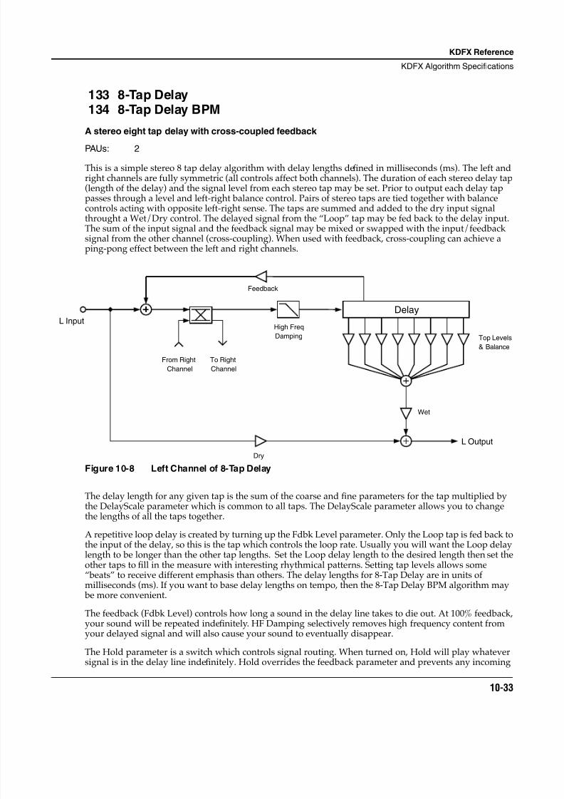
8/21/2019 MR_K2661
http://slidepdf.com/reader/full/mrk2661 115/499
KDFX Reference
KDFX Algorithm Specifications
10-33
133 8-Tap Delay134 8-Tap Delay BPM
A stereo eight tap delay with cross-coupled feedback
PAUs: 2
This is a simple stereo 8 tap delay algorithm with delay lengths defined in milliseconds (ms). The left andright channels are fully symmetric (all controls affect both channels). The duration of each stereo delay tap(length of the delay) and the signal level from each stereo tap may be set. Prior to output each delay tappasses through a level and left-right balance control. Pairs of stereo taps are tied together with balancecontrols acting with opposite left-right sense. The taps are summed and added to the dry input signalthrought a Wet/Dry control. The delayed signal from the “Loop” tap may be fed back to the delay input.The sum of the input signal and the feedback signal may be mixed or swapped with the input/feedbacksignal from the other channel (cross-coupling). When used with feedback, cross-coupling can achieve aping-pong effect between the left and right channels.
Figure 10-8 Left Channel of 8-Tap Delay
The delay length for any given tap is the sum of the coarse and fine parameters for the tap multiplied bythe DelayScale parameter which is common to all taps. The DelayScale parameter allows you to changethe lengths of all the taps together.
A repetitive loop delay is created by turning up the Fdbk Level parameter. Only the Loop tap is fed back tothe input of the delay, so this is the tap which controls the loop rate. Usually you will want the Loop delay
length to be longer than the other tap lengths. Set the Loop delay length to the desired length then set theother taps to fill in the measure with interesting rhythmical patterns. Setting tap levels allows some“beats” to receive different emphasis than others. The delay lengths for 8-Tap Delay are in units ofmilliseconds (ms). If you want to base delay lengths on tempo, then the 8-Tap Delay BPM algorithm may be more convenient.
The feedback (Fdbk Level) controls how long a sound in the delay line takes to die out. At 100% feedback,your sound will be repeated indefinitely. HF Damping selectively removes high frequency content fromyour delayed signal and will also cause your sound to eventually disappear.
The Hold parameter is a switch which controls signal routing. When turned on, Hold will play whateversignal is in the delay line indefinitely. Hold overrides the feedback parameter and prevents any incoming
L Input
& Balance
L Output
Top Levels
Dry
Wet
Feedback
Delay
High Freq
Damping
From Right
Channel
To Right
Channel
8/21/2019 MR_K2661
http://slidepdf.com/reader/full/mrk2661 116/499
10-34
KDFX Reference
KDFX Algorithm Specifications
signal from entering the delay. You may have to practice using the Hold parameter. Each time your soundgoes through the delay, it is reduced by the feedback amount. If feedback is fairly low and you turn onHold at the wrong moment, you can get a disconcerting jump in level at some point in the loop. The Holdparameter has no effect on the Wet/Dry or HF Damping parameters, which continue to work as usual, soif there is some HF Damping, the delay will eventually die out.
See also the versions of these algorithms which specify delay lengths in terms of tempo and beats.
Parameters for Algorithm 133 8-Tap Delay
Page 1
Page 2
Page 3
Page 4
Wet/Dry The relative amount of input signal and delay signal that is to appear in the final effectoutput mix. When set to 0%, the output is taken only from the input (dry). When set to100%, the output is all wet.
Out Gain The overall gain or amplitude at the output of the effect.
Wet/Dry 0 to 100%wet Out Gain Off, -79.0 to 24.0 dB
Fdbk Level 0 to 100%
Xcouple 0 to 100% Dry Bal -100 to 100%
HF Damping 16 Hz to 25088 Hz Hold On or Off
Loop Crs 0 to 5100 ms DelayScale 0.00x to 10.00x
Loop Fine -20 to 20 ms
Tap1 Crs 0 to 5100 ms Tap3 Crs 0 to 5100 ms
Tap1 Fine -20 to 20 ms Tap3 Fine -20 to 20 ms
Tap2 Crs 0 to 5100 ms Tap4 Crs 0 to 5100 ms
Tap2 Fine -20 to 20 ms Tap4 Fine -20 to 20 ms
Tap5 Crs 0 to 5100 ms Tap7 Crs 0 to 5100 ms
Tap5 Fine -20 to 20 ms Tap7 Fine -20 to 20 ms
Tap6 Crs 0 to 5100 ms Tap8 Crs 0 to 5100 ms
Tap6 Fine -20 to 20 ms Tap8 Fine -20 to 20 ms
Tap1 Level 0 to 100 % Tap5 Level 0 to 100 %
Tap2 Level 0 to 100 % Tap6 Level 0 to 100 %
Tap3 Level 0 to 100 % Tap7 Level 0 to 100 %
Tap4 Level 0 to 100 % Tap8 Level 0 to 100 %
Tap1/-5Bal -100 to 100 % Tap3/-7Bal -100 to 100 %Tap2/-6Bal -100 to 100 % Tap4/-8Bal -100 to 100 %
8/21/2019 MR_K2661
http://slidepdf.com/reader/full/mrk2661 117/499
KDFX Reference
KDFX Algorithm Specifications
10-35
Fdbk Level The percentage of the delayed signal to feed back or return to the delay input. Turning upthe feedback will cause the effect to repeatedly echo or act as a crude reverb.
Xcouple 8 Tap Delay is a stereo effect. The cross coupling control lets you send the feedback from achannel to its own input (0% cross coupling) or to the other channel’s input (100% crosscoupling) or somewhere in between. This control has no effect if the Fdbk Level control isset to 0%.
HF Damping The -3 dB frequency in Hz of a one pole lowpass filter (-6 dB/octave) placed in front of thedelay line. The filter is specified for a signal passing through the filter once. Multiplepasses through the feedback will cause the signal to become more and more dull.
Dry Bal The left-right balance of the dry signal. A setting of -100% allows only the left dry signal topass to the left output, while a setting of 100% lets only the right dry signal pass to theright output. At 0%, equal amounts of the left and right dry signals pass to their respectiveoutputs.
Hold A switch which when turned on, locks any signal currently in the delay to play until Holdis turned off. When Hold is on, no signal can enter the delay and Feedback is set to 100%
behind the scenes. Hold does not affect the HF Damping or Wet/Dry mix.Loop Crs The coarse delay length of the Loop tap. If the feedback is turned up, this parameter sets
the repeating delay loop length. The resolution of the coarse adjust is 20 milliseconds, butfiner resolution can be obtained using the Loop Fine parameter. The maximum delaylength is 5.10 seconds (5100ms) for the 8-Tap Delay.
Loop Fine A fine adjustment to the Loop tap delay length. The delay resolution is 0.2 milliseconds(ms). Loop Fine is added to Loop Crs (coarse) to get the actual delay length.
Tapn Crs The coarse delay lengths of the output taps (n = 1...8). The resolution of the coarse adjustis 20 milliseconds, but finer resolution can be obtained using the Tapn Fine parameters.The maximum delay length is 5.1 seconds (5100ms) for the 8-Tap Delay.
Tapn Fine A fine adjustment to the output tap delay lengths (n = 1...8). The delay resolution is 0.2
milliseconds (ms). Tapn Fine is added to Tapn Crs (coarse) to get actual delay lengths.
Tapn Level The amount of signal from each of the taps (n = 1...8) which get sent to the output.
Tapm/-n Bal The left-right balance of each of the stereo taps. The balances are controlled in pairs oftaps: 1 & 5, 2 & 6, 3 & 7, and 4 & 8. The balance controls work in opposite directions for thetwo taps in the pair. When the balance is set to -100%, the first tap of the pair is fully rightwhile the second is fully left. At 0%, equal amounts of the left and right taps pass to theirrespective outputs.
Algorithm 134: 8-Tap Delay BPM
In this Algorithm the delay length for any given tap is determined by the tempo, expressed in beats perminute (BPM), and the delay length of the tap expressed in beats (bts). The tempo alters all tap lengths
together. With the tempo in beats per minute and delay lengths in beats, you can calculate the length of adelay in seconds as beats/tempo * 60 (sec/min). IMPORTANT NOTE: KDFX has a limited amount ofdelay memory available (over 5 seconds for 8 Tap Delay BPM). When slow tempos and/or long lengthsare specified, you may run out of delay memory, at which point the delay length will be cut in half. Whenyou slow down the tempo, you may find the delays suddenly getting shorter.
A repetitive loop delay is created by turning up the feedback parameter (Fdbk Level). Only the Loop tap isfed back to the input of the delay, so this is the tap which controls the loop rate. Usually you will want theLoop tap (LoopLength parameter) to be longer than the other tap lengths. To repeat a pattern on a 4/4measure (4 beats per measure) simply set LoopLength to 4 bts. The output taps can then be used to fill in
8/21/2019 MR_K2661
http://slidepdf.com/reader/full/mrk2661 118/499
10-36
KDFX Reference
KDFX Algorithm Specifications
the measure with interesting rhythmical patterns. Setting tap levels allows some “beats” to receivedifferent emphasis than others.
Parameters
Page 1
Page 2
Page 3
Page 4
Tempo Basis for the delay lengths, as referenced to a musical tempo in bpm (beats per minute).When this parameter is set to “System”, the tempo is locked to the internal sequencertempo or to incoming MIDI clocks. When it is set to “System”, sources (FUNs, LFOs, ASRsetc.) will have no effect on the Tempo parameter.
LoopLength The delay length of the Loop tap. If the feedback is turned up, this parameter sets therepeating delay loop length. LoopLength sets the loop delay length as a tempo beatduration. The tempo is specified with the Tempo parameter and the delay length is givenin beats (bts). The delay length in seconds is calculated as beats/tempo * 60 (sec/min).
Tapn Delay The delay lengths of the taps (n = 1...8) as tempo beat durations. The tempo is specifiedwith the Tempo parameter and the delay length is given in beats (bts). The delay length inseconds is calculated as beats/tempo * 60 (sec/min). Use the output taps to createinteresting rhythmic patterns within the repeating loop.
Wet/Dry 0 to 100%wet Out Gain Off, -79.0 to 24.0 dB
Fdbk Level 0 to 100% Tempo System, 1 to 255 BPM
Xcouple 0 to 100% Dry Bal -100 to 100%
HF Damping 16 Hz to 25088 Hz Hold On or Off
LoopLength 0 to 32 bts
Tap1 Delay 0 to 32 bts Tap5 Delay 0 to 32 bts
Tap2 Delay 0 to 32 bts Tap6 Delay 0 to 32 bts
Tap3 Delay 0 to 32 bts Tap7 Delay 0 to 32 bts
Tap4 Delay 0 to 32 bts Tap8 Delay 0 to 32 bts
Tap1 Level 0 to 100 % Tap5 Level 0 to 100 %
Tap2 Level 0 to 100 % Tap6 Level 0 to 100 %
Tap3 Level 0 to 100 % Tap7 Level 0 to 100 %
Tap4 Level 0 to 100 % Tap8 Level 0 to 100 %
Tap1 Bal -100 to 100 % Tap5 Bal -100 to 100 %
Tap2 Bal -100 to 100 % Tap6 Bal -100 to 100 %
Tap3 Bal -100 to 100 % Tap7 Bal -100 to 100 %
Tap4 Bal -100 to 100 % Tap8 Bal -100 to 100 %
8/21/2019 MR_K2661
http://slidepdf.com/reader/full/mrk2661 119/499
KDFX Reference
KDFX Algorithm Specifications
10-37
135 Spectral 4-Tap136 Spectral 6-Tap
Tempo based 4 and 6 tap delays with added shapers and resonant comb filters on each tap
PAUs: 2 for Spectral 4-Tap3 for Spectral 6-Tap
Spectral 4 Tap and Spectral 6 Tap are respectively 2 and 3 processing allocation unit (PAU) tempo basedmulti-tap delay effects. They are similar to a simple 4 and 6 tap delays with feedback, but have theirfeedback and output taps modified with shapers and filters. In the feedback path of each are a diffuser,hipass filter, lopass filter, and imager. Each delay tap has a shaper, comb filter, balance and level controlswith the exception of Tap 1, which does not have a comb filter (Figure 1).
Diffusers add a quality that can be described as “smearing” the feedback signal. The more a signal has been regenerated through feedback and consequently fed through the diffuser, the more it is smeared. Itrequires two parameters, one for the duration a signal is smeared labeled Diff Delay, and the other for theamount it is smeared labeled Diff Amt. Positive diffusion settings will add diffusion while maintaining
image integrity. Negative diffusion amounts will cause the feedback image to lose image integrity and become wide. Short Diff Delay settings have subtle smearing effects. Increasing Diff Delay will be morenoticeable, and long delay settings will take on a ringy resonant quality. To disable the diffuser, both DiffDelay and Diff Amt should be set to zero.
Two 1 pole 6dB/oct filters are also in the feedback path: hipass and lopass. The hipass filter roll-offfrequency is controlled with LF Damping, and the lopass filter roll-off frequency is controlled by HFDamping.
The imager (found on PARAM2) shifts the stereo input image when fed through feedback. Small positiveor negative values shift the image to the right or left respectively. Larger values shift the image so muchthat the image gets scrambled through each feedback generation.
On each output tap is a shaper. For an overview of shaper functionality, refer to the section on shapers inthe Musician’s Guide. The Spectral Multi-Tap shapers offer 4 shaping loops as opposed to 8 found in theVAST shapers, but can allow up to 6.00x intensity (Figure 2). Immediately following the shapers on taps 2and above are resonant comb filters tuned in semitones. These comb filters make the taps become pitched.When a comb filter is in use, the shaper before it can be used to intensify these pitched qualities.
Each tap also has separate balance and level controls.
Since these are tempo based effects, tap delay values and feedback delay (labeled LoopLength onPARAM2) values are set relative to a beat. The beat duration is set be adjusting Tempo in BPM. The tempocan be synced to the system clock by setting Tempo to System. Each tap’s delay is adjusted relative to 1 beat, in 1/24 beat increments. Notice that 24 is a musically useful beat division because it can divide a beatinto halves, 3rds, 4ths, 6ths, 8ths, 12ths, and of course 24ths. For example, setting LoopLength to “1 12/24bts” will put the feedback tap at 1 1/2 beats (dotted quarter note in 4/4 time) of delay making thefeedback repetition occur every one and a half beats. This is equivalent to 3/4 of a second at 120 BPM.
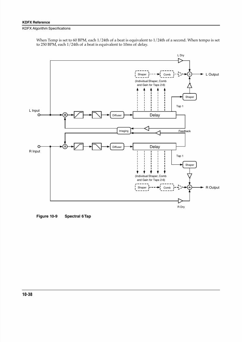
8/21/2019 MR_K2661
http://slidepdf.com/reader/full/mrk2661 120/499
10-38
KDFX Reference
KDFX Algorithm Specifications
When Temp is set to 60 BPM, each 1/24th of a beat is equivalent to 1/24th of a second. When tempo is setto 250 BPM, each 1/24th of a beat is equivalent to 10ms of delay.
Figure 10-9 Spectral 6 Tap
R Input
R Output
R Dry
Delay
Imaging
(Individual Shaper, Comb
and Gain for Taps 2-6)
Shaper Comb
Shaper
Delay
Shaper
CombShaper
L Dry
L Input
L Output
Feedback
Tap 1
Tap 1
(Individual Shaper, Comb
and Gain for Taps 2-6)
Diffuser
Diffuser
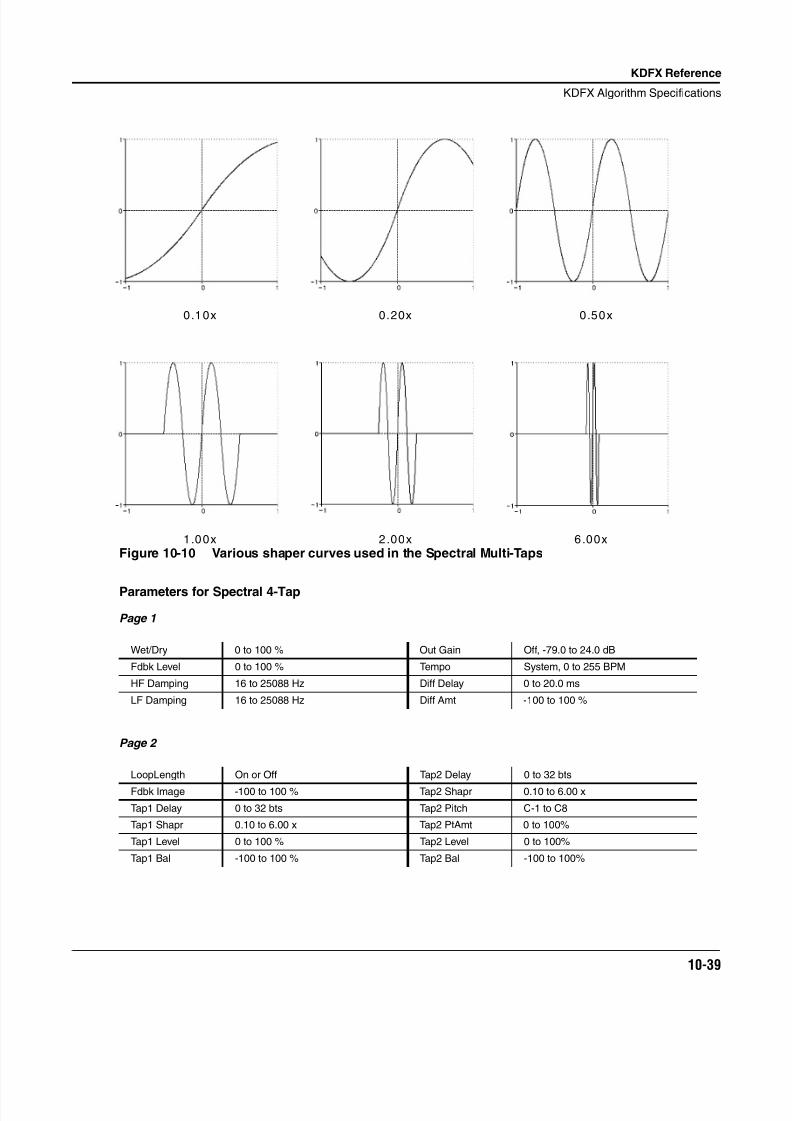
8/21/2019 MR_K2661
http://slidepdf.com/reader/full/mrk2661 121/499
KDFX Reference
KDFX Algorithm Specifications
10-39
Figure 10-10 Various shaper curves used in the Spectral Multi-Taps
Parameters for Spectral 4-Tap
Page 1
Page 2
Wet/Dry 0 to 100 % Out Gain Off, -79.0 to 24.0 dB
Fdbk Level 0 to 100 % Tempo System, 0 to 255 BPM
HF Damping 16 to 25088 Hz Diff Delay 0 to 20.0 ms
LF Damping 16 to 25088 Hz Diff Amt -100 to 100 %
LoopLength On or Off Tap2 Delay 0 to 32 bts
Fdbk Image -100 to 100 % Tap2 Shapr 0.10 to 6.00 x
Tap1 Delay 0 to 32 bts Tap2 Pitch C-1 to C8
Tap1 Shapr 0.10 to 6.00 x Tap2 PtAmt 0 to 100%
Tap1 Level 0 to 100 % Tap2 Level 0 to 100%
Tap1 Bal -100 to 100 % Tap2 Bal -100 to 100%
0.20x0.10x 0.50x
1.00x 2.00x 6.00x
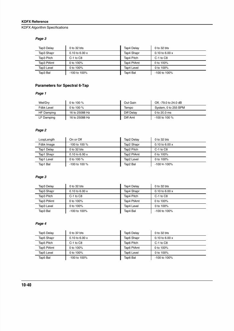
8/21/2019 MR_K2661
http://slidepdf.com/reader/full/mrk2661 122/499
10-40
KDFX Reference
KDFX Algorithm Specifications
Page 3
Parameters for Spectral 6-Tap
Page 1
Page 2
Page 3
Page 4
Tap3 Delay 0 to 32 bts Tap4 Delay 0 to 32 bts
Tap3 Shapr 0.10 to 6.00 x Tap4 Shapr 0.10 to 6.00 x
Tap3 Pitch C-1 to C8 Tap4 Pitch C-1 to C8Tap3 PtAmt 0 to 100% Tap4 PtAmt 0 to 100%
Tap3 Level 0 to 100% Tap4 Level 0 to 100%
Tap3 Bal -100 to 100% Tap4 Bal -100 to 100%
Wet/Dry 0 to 100 % Out Gain Off, -79.0 to 24.0 dB
Fdbk Level 0 to 100 % Tempo System, 0 to 255 BPM
HF Damping 16 to 25088 Hz Diff Delay 0 to 20.0 ms
LF Damping 16 to 25088 Hz Diff Amt -100 to 100 %
LoopLength On or Off Tap2 Delay 0 to 32 bts
Fdbk Image -100 to 100 % Tap2 Shapr 0.10 to 6.00 x
Tap1 Delay 0 to 32 bts Tap2 Pitch C-1 to C8
Tap1 Shapr 0.10 to 6.00 x Tap2 PtAmt 0 to 100%
Tap1 Level 0 to 100 % Tap2 Level 0 to 100%
Tap1 Bal -100 to 100 % Tap2 Bal -100 to 100%
Tap3 Delay 0 to 32 bts Tap4 Delay 0 to 32 bts
Tap3 Shapr 0.10 to 6.00 x Tap4 Shapr 0.10 to 6.00 x
Tap3 Pitch C-1 to C8 Tap4 Pitch C-1 to C8
Tap3 PtAmt 0 to 100% Tap4 PtAmt 0 to 100%
Tap3 Level 0 to 100% Tap4 Level 0 to 100%
Tap3 Bal -100 to 100% Tap4 Bal -100 to 100%
Tap5 Delay 0 to 32 bts Tap6 Delay 0 to 32 bts
Tap5 Shapr 0.10 to 6.00 x Tap6 Shapr 0.10 to 6.00 x
Tap5 Pitch C-1 to C8 Tap6 Pitch C-1 to C8
Tap5 PtAmt 0 to 100% Tap6 PtAmt 0 to 100%
Tap5 Level 0 to 100% Tap6 Level 0 to 100%
Tap5 Bal -100 to 100% Tap6 Bal -100 to 100%
8/21/2019 MR_K2661
http://slidepdf.com/reader/full/mrk2661 123/499
KDFX Reference
KDFX Algorithm Specifications
10-41
Wet/Dry The relative amount of input signal and effected signal that is to appear in the final effectoutput mix. When set to 0%, the output is taken only from the input (dry). When set to100%, the output is all wet. Negative values polarity invert the wet signal.
Out Gain The overall gain or amplitude at the output of the effect.
Fdbk Level The amount that the feedback tap is fed to the input of the delay.
HF Damping The amount of high frequency content of the signal to the input of the delay. This controldetermines the cutoff frequency of the one-pole (-6dB/octave) lopass filters.
LF Damping The amount of low frequency content of the signal to the input of the delay. This controldetermines the cutoff frequency of the one-pole (-6dB/octave) lopass filters.
Tempo Basis for the rates of the delay times, as referenced to a musical tempo in BPM (beats perminute). When this parameter is set to “System”, the tempo is locked to the internalsequencer tempo or to incoming MIDI clocks. When it is set to “System”, sources (FUNs,LFOs, ASRs etc.) will have no effect on the Tempo parameter.
Diff Dly The length that the diffuser smears the signal sent to the input of the delay.
Diff Amt The intensity that the diffuser smears the signal sent to the input of the delay. Negativevalues decorrelate the stereo signal.
LoopLength The delay length of the feedback tap in 24ths of a beat.
Fdbk Image Sets the amount the stereo image is shifted each time it passes through the feedback line.
Tap n Delay Adjusts the length of time in 24ths of a beat each output tap is delayed.
Tap n Shapr Adjusts the intensity of the shaper at each output tap.
Tap n Pitch Adjusts the frequency in semitones of the comb filter at each output tap.
Tap n PtAmt Adjusts the intensity of the comb filter at each output tap.
Tap n Level Adjusts the relative amplitude that each output tap is heard.
Tap n Bal Adjusts the left/right balance of each output tap. Negative values bring down the rightchannel, and positive values bring down the left channel.
8/21/2019 MR_K2661
http://slidepdf.com/reader/full/mrk2661 124/499
10-42
KDFX Reference
KDFX Algorithm Specifications
138 Degen Regen BPM
Long delay allowing loop instability
PAUs: 4 each
Degen Regen BPM starts as a simple mono delay line with feedback. However with the Fdbk Gain andDist Drive parameters, the algorithm can be pushed hard into instability. When Degen Regen BPM isunstable, your sound gets a little louder on each pass through the delay line. Eventually the sound will hitdigital clipping when the effects processor runs out of headroom bits. To keep this all under control, a soft-knee compressor has been included inside the delay line loop. With the compressor properly set, thesound never reaches digital clipping, but it does become more and more distorted as it gets pushed harderand harder into the compressor. To make things really nasty, there’s also a distortion in the delay path.(The distortion parameters are on the PARAM4 page with the compressor parameters.)
Degen Regen BPM uses all 4 PAUs available for insert effects. With the resources of all 4 PAUs available,Degen Regen BPM lets you set the longest mono delay line available in KDFX which is just over 20seconds. If you want a long delay, this is the algorithm to do it. (You don’t have to over-drive the feedbackor use the distortion.)
The delay has two output taps in addition to the feedback tap. Each tap may be moved along the delay lineusing an LFO (internal to the effects processor). The output taps have separate controls for level andpanning (in the stereo configurations).
Throw a few filters into the delay line loop, and you get a pretty versatile delay line. The available filtersare highpass (LF Damping), lowpass (HF Damping), bass shelf, treble shelf, and two parametric EQs(Mid1, Mid2).
For details about the compressor see the documentation for SoftKneeCompress. For the distortion see thedocumentation for Mono Distortion.
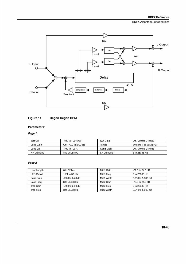
8/21/2019 MR_K2661
http://slidepdf.com/reader/full/mrk2661 125/499
KDFX Reference
KDFX Algorithm Specifications
10-43
Figure 11 Degen Regen BPM
Parameters:
Page 1
Page 2
Wet/Dry -100 to 100%wet Out Gain Off, -79.0 to 24.0 dB
Loop Gain Off, -79.0 to 24.0 dB Tempo System, 1 to 255 BPM
Loop Lvl -100 to 100% Send Gain Off, -79.0 to 24.0 dB
HF Damping 8 to 25088 Hz LF Damping 8 to 25088 Hz
LoopLength 0 to 32 bts Mid1 Gain -79.0 to 24.0 dB
LFO Period 1/24 to 32 bts Mid1 Freq 8 to 25088 Hz
Bass Gain -79.0 to 24.0 dB Mid1 Width 0.010 to 5.000 oct
Bass Freq 8 to 25088 Hz Mid2 Gain -79.0 to 24.0 dB
Treb Gain -79.0 to 24.0 dB Mid2 Freq 8 to 25088 Hz
Treb Freq 8 to 25088 Hz Mid2 Width 0.010 to 5.000 oct
Delay
Compressor Distortion Filters
Pan
Pan
L Input
R Input
L Output
R Output
Dry
Dry
Level
Level
Wet
Feedback
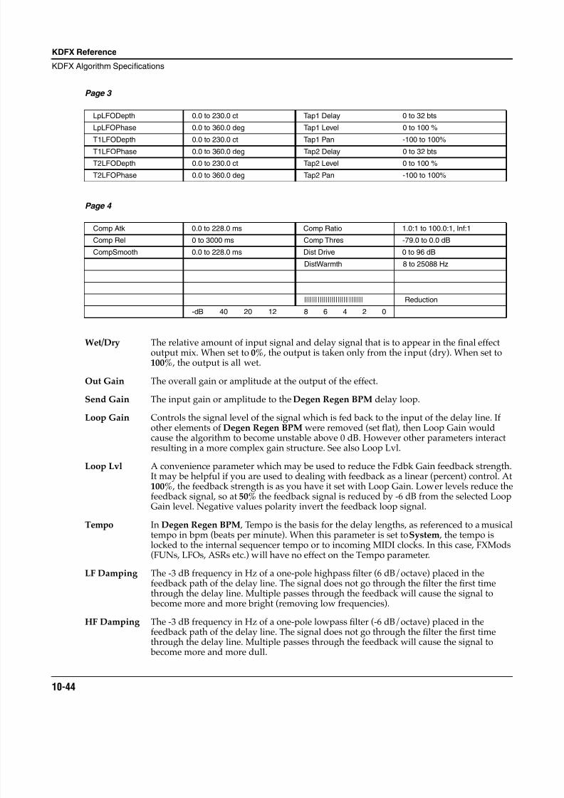
8/21/2019 MR_K2661
http://slidepdf.com/reader/full/mrk2661 126/499
10-44
KDFX Reference
KDFX Algorithm Specifications
Page 3
Page 4
Wet/Dry The relative amount of input signal and delay signal that is to appear in the final effectoutput mix. When set to 0% , the output is taken only from the input (dry). When set to100% , the output is all wet.
Out Gain The overall gain or amplitude at the output of the effect.
Send Gain The input gain or amplitude to the Degen Regen BPM delay loop.
Loop Gain Controls the signal level of the signal which is fed back to the input of the delay line. Ifother elements of Degen Regen BPM were removed (set flat), then Loop Gain wouldcause the algorithm to become unstable above 0 dB. However other parameters interactresulting in a more complex gain structure. See also Loop Lvl.
Loop Lvl A convenience parameter which may be used to reduce the Fdbk Gain feedback strength.It may be helpful if you are used to dealing with feedback as a linear (percent) control. At100% , the feedback strength is as you have it set with Loop Gain. Lower levels reduce thefeedback signal, so at 50% the feedback signal is reduced by -6 dB from the selected LoopGain level. Negative values polarity invert the feedback loop signal.
Tempo In Degen Regen BPM , Tempo is the basis for the delay lengths, as referenced to a musicaltempo in bpm (beats per minute). When this parameter is set to System , the tempo islocked to the internal sequencer tempo or to incoming MIDI clocks. In this case, FXMods
(FUNs, LFOs, ASRs etc.) will have no effect on the Tempo parameter.LF Damping The -3 dB frequency in Hz of a one-pole highpass filter (6 dB/octave) placed in the
feedback path of the delay line. The signal does not go through the filter the first timethrough the delay line. Multiple passes through the feedback will cause the signal to become more and more bright (removing low frequencies).
HF Damping The -3 dB frequency in Hz of a one-pole lowpass filter (-6 dB/octave) placed in thefeedback path of the delay line. The signal does not go through the filter the first timethrough the delay line. Multiple passes through the feedback will cause the signal to become more and more dull.
LpLFODepth 0.0 to 230.0 ct Tap1 Delay 0 to 32 bts
LpLFOPhase 0.0 to 360.0 deg Tap1 Level 0 to 100 %
T1LFODepth 0.0 to 230.0 ct Tap1 Pan -100 to 100%T1LFOPhase 0.0 to 360.0 deg Tap2 Delay 0 to 32 bts
T2LFODepth 0.0 to 230.0 ct Tap2 Level 0 to 100 %
T2LFOPhase 0.0 to 360.0 deg Tap2 Pan -100 to 100%
Comp Atk 0.0 to 228.0 ms Comp Ratio 1.0:1 to 100.0:1, Inf:1
Comp Rel 0 to 3000 ms Comp Thres -79.0 to 0.0 dB
CompSmooth 0.0 to 228.0 ms Dist Drive 0 to 96 dB
DistWarmth 8 to 25088 Hz
|||||||||||||||||||||||||||||| Reduction
-dB 40 20 12 8 6 4 2 0
8/21/2019 MR_K2661
http://slidepdf.com/reader/full/mrk2661 127/499
KDFX Reference
KDFX Algorithm Specifications
10-45
LoopLength The delay length of the feedback tap. If feedback is turned up from 0% , this parameter setsthe repeating delay loop length. In Degen Regen BPM , the loop length is specified as afraction or multiple of the tempo, in “beats.” The length of a delay loop in seconds can becalculated from beats as T = (beats/tempo) 60.
LFO Period The feedback tap and the output taps lengths can be modulated with an LFO internal tothe effects processor. The rate at which the tap positions move are tied to a commonperiod control (time for one complete cycle) which is expressed in beats. The LFO Periodcontrol is specific to Degen Regen BPM. The depth of modulation is specified by theLpLFODepth parameter. Frequency in Hz can be calculated from the period in beats asF = tempo/(beats 60). Since this moving delay tap is part of the feedback path throughthe delay, subsequent passes of the signal through the delay may result in some strangepitch modulations. It is possible to set LFO Period with LoopLength so that alternatepasses through the loop detune then retune the signal (for example, set the LFO period todouble the LoopLength). The maximum pitch shift up is not identical to the maximumpitch shift down, so the alternating detune/retune effect is not perfect.
Bass Gain The amount of boost or cut in dB that the bass shelving filter should apply to the lowfrequency signal components. Every increase of 6 dB approximately doubles the
amplitude of the signal. Positive values boost the bass signal below the specifiedfrequency. Negative values cut the bass signal below the specified frequency. Since thefilters are in the delay feedback loop, the cut or boost is cumulative on each pass thesound makes through the loop.
Bass Freq The center frequency of the bass shelving filter in intervals of one semitone.
Treb Gain The amount of boost or cut in dB that the treble shelving filter should apply to the highfrequency signal components. Every increase of 6 dB approximately doubles theamplitude of the signal. Positive values boost the treble signal above the specifiedfrequency. Negative values cut the treble signal above the specified frequency. Since thefilters are in the delay feedback loop, the cut or boost is cumulative on each pass thesound makes through the loop.
Treb Freq The center frequency of the treble shelving filter in intervals of one semitone.Midn Gain The amount of boost or cut in dB that the parametric filter should apply to the specified
signal band. Every increase of 6 dB approximately doubles the amplitude of the signal.Positive values boost the signal at the specified frequency. Negative values cut the signalat the specified frequency. Since the filters are in the delay feedback loop, the cut or boostis cumulative on each pass the sound makes through the loop.
Midn Freq The center frequency of the parametric EQ in intervals of one semitone. The boost or cutwill be a maximum at this frequency.
Midn Width The bandwidth of the parametric EQ may be adjusted. You specify the bandwidth inoctaves. Small values result in a very narrow (high-Q) filter response. Large values resultin a very broad response.
LpLFODepth The feedback (loop) delay tap will have its position modulated by an LFO (internal to theFX processor) if the LpLFODepth parameter is non-zero. A moving tap on a delay line willresult in a pitch shift, and LpLFODepth sets the maximum pitch shift (up and down) incents.
LpLFOPhase Specifies the phase angle of the feedback (loop) LFO relative to the output tap LFOs andthe system (or MIDI) tempo clock, if turned on (see Tempo). For example, if one LFO is setto 0° and another is set to 180° , then when one LFO delay tap is at its shortest, the otherwill be at its longest. If the system (or MIDI) tempo clock is turned on , the LFOs aresynchronized to the clock with absolute phase.
8/21/2019 MR_K2661
http://slidepdf.com/reader/full/mrk2661 128/499
10-46
KDFX Reference
KDFX Algorithm Specifications
TnLFODepth The output delay taps (1 and 2) will have their positions modulated by an LFO (internal tothe FX processor) if the TnLFODepth parameter is non-zero. A moving tap on a delay linewill result in a pitch shift, and TnLFODepth sets the maximum pitch shift (up and down)in cents.
TnLFOPhase Specifies the phase angle of the output LFO tap (1 or 2) relative to the other output LFOtap, the feedback (loop) LFO tap, and the system (or MIDI) tempo clock, if turned on (seeTempo). For example, if one LFO is set to 0° and another is set to 180° , then when one LFOdelay tap is at its shortest, the other will be at its longest. If the system (or MIDI) tempoclock is turned on, the LFOs are synchronized to the clock with absolute phase.
Tapn Delay The delay length of the output tap 1 or 2. In Degen Regen BPM , the tap length is specifiedas a fraction or multiple of the tempo, in “beats.” The length of a delay tap in seconds can be calculated from beats as T = (beats/tempo) 60.
Tapn Level The level of the output tap 1 or 2 expressed as a percent.
Tapn Pan The output taps 1 and 2 are mono sources that can be panned to the left or right outputchannels. A pan setting of -100% is fully left while 100% is fully right.
Comp Atk The time for the compressor to start to cut in when there is an increase in signal level(attack) above the threshold.
Comp Rel The time for the compressor to stop compressing when there is a reduction in signal level(release) from a signal level above the threshold.
CompSmooth A lowpass filter in the compressor control signal path. It is intended to smooth the outputof the expander’s envelope detector. Smoothing will affect the attack or release timeswhen the smoothing time is longer than one of the other times.
Comp Ratio The compression ratio. High ratios are highly compressed; low ratios are moderatelycompressed.
Comp Thres The threshold level in dBFS (decibels relative to full scale) above which the signal begins
to be compressed.
Dist Drive Applies a boost to the feedback signal to overdrive the distortion algorithm. Whenoverdriven, the distortion algorithm will soft-clip the signal. Since distortion drive willmake your signal very loud, you may have to reduce the feedback amount or turn on thecompressor as the drive is increased.
DistWarmth A lowpass filter in the distortion control path. This filter may be used to reduce some ofthe harshness of some distortion settings without reducing the bandwidth of the signal.
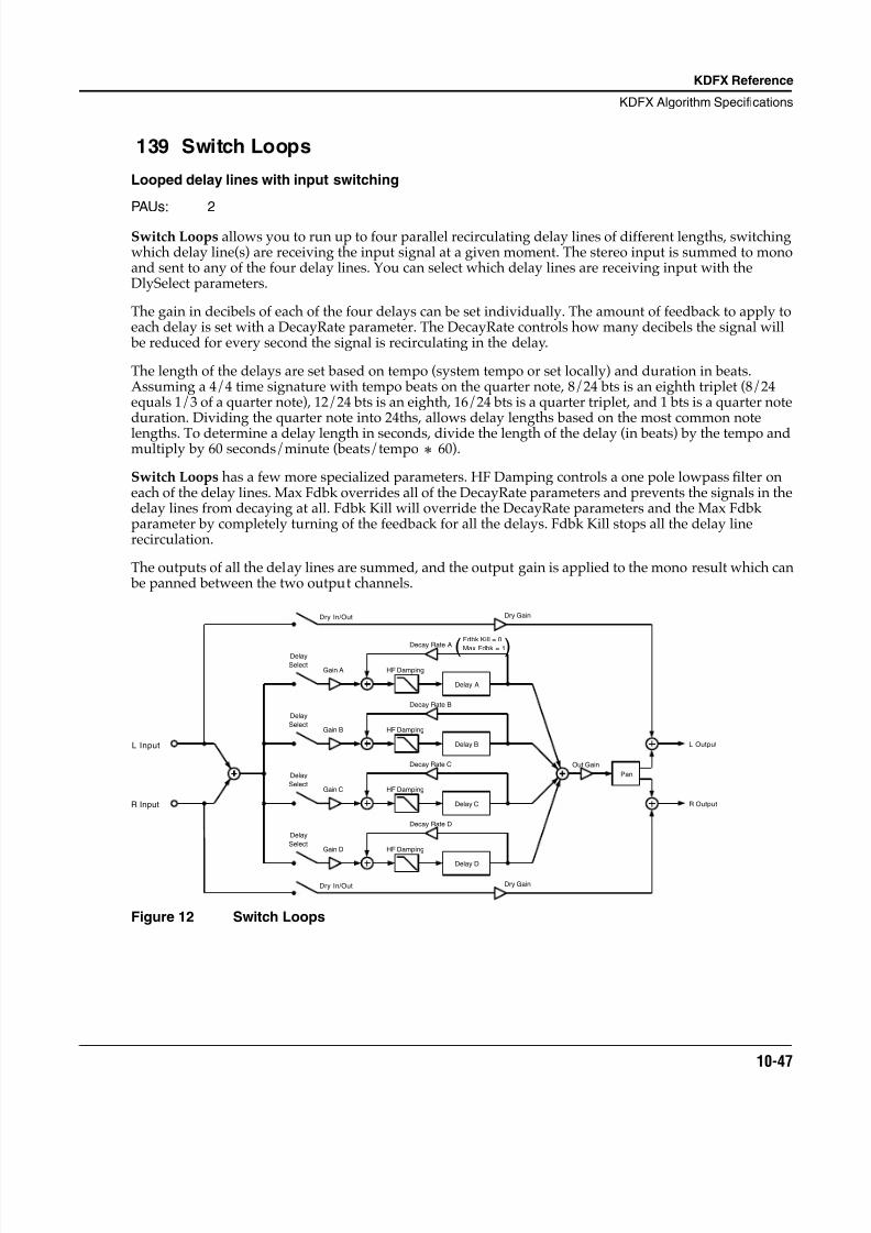
8/21/2019 MR_K2661
http://slidepdf.com/reader/full/mrk2661 129/499
KDFX Reference
KDFX Algorithm Specifications
10-47
139 Switch Loops
Looped delay lines with input switching
PAUs: 2
Switch Loops allows you to run up to four parallel recirculating delay lines of different lengths, switchingwhich delay line(s) are receiving the input signal at a given moment. The stereo input is summed to monoand sent to any of the four delay lines. You can select which delay lines are receiving input with theDlySelect parameters.
The gain in decibels of each of the four delays can be set individually. The amount of feedback to apply toeach delay is set with a DecayRate parameter. The DecayRate controls how many decibels the signal will be reduced for every second the signal is recirculating in the delay.
The length of the delays are set based on tempo (system tempo or set locally) and duration in beats.Assuming a 4/4 time signature with tempo beats on the quarter note, 8/24 bts is an eighth triplet (8/24equals 1/3 of a quarter note), 12/24 bts is an eighth, 16/24 bts is a quarter triplet, and 1 bts is a quarter noteduration. Dividing the quarter note into 24ths, allows delay lengths based on the most common note
lengths. To determine a delay length in seconds, divide the length of the delay (in beats) by the tempo andmultiply by 60 seconds/minute (beats/tempo 60).
Switch Loops has a few more specialized parameters. HF Damping controls a one pole lowpass filter oneach of the delay lines. Max Fdbk overrides all of the DecayRate parameters and prevents the signals in thedelay lines from decaying at all. Fdbk Kill will override the DecayRate parameters and the Max Fdbkparameter by completely turning of the feedback for all the delays. Fdbk Kill stops all the delay linerecirculation.
The outputs of all the delay lines are summed, and the output gain is applied to the mono result which can be panned between the two output channels.
Figure 12 Switch Loops
L Input
R Input
HF Damping
Delay A
Decay Rate A
Gain A
Delay
Select
Fdbk Kill = 0
Max Fdbk = 1
( )
HF Damping
Delay B
Decay Rate B
Gain B
Delay
Select
HF Damping
Delay C
Decay Rate C
Gain C
Delay
Select
HF Damping
Delay D
Decay Rate D
Gain D
Delay
Select
Out Gain
Pan
Dry In/Out Dry Gain
Dry In/Out Dry Gain
L Output
R Output
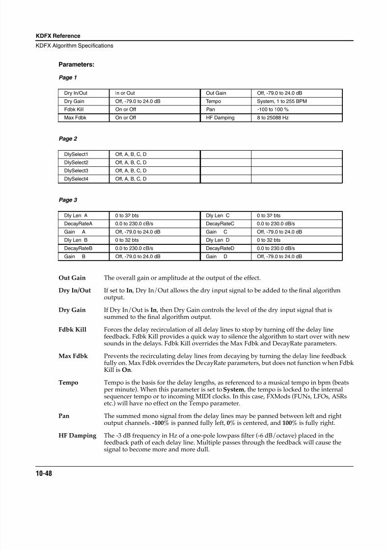
8/21/2019 MR_K2661
http://slidepdf.com/reader/full/mrk2661 130/499
10-48
KDFX Reference
KDFX Algorithm Specifications
Parameters:
Page 1
Page 2
Page 3
Out Gain The overall gain or amplitude at the output of the effect.
Dry In/Out If set to In , Dry In/Out allows the dry input signal to be added to the final algorithmoutput.
Dry Gain If Dry In/Out is In , then Dry Gain controls the level of the dry input signal that issummed to the final algorithm output.
Fdbk Kill Forces the delay recirculation of all delay lines to stop by turning off the delay linefeedback. Fdbk Kill provides a quick way to silence the algorithm to start over with newsounds in the delays. Fdbk Kill overrides the Max Fdbk and DecayRate parameters.
Max Fdbk Prevents the recirculating delay lines from decaying by turning the delay line feedbackfully on. Max Fdbk overrides the DecayRate parameters, but does not function when FdbkKill is On.
Tempo Tempo is the basis for the delay lengths, as referenced to a musical tempo in bpm (beatsper minute). When this parameter is set to System , the tempo is locked to the internalsequencer tempo or to incoming MIDI clocks. In this case, FXMods (FUNs, LFOs, ASRsetc.) will have no effect on the Tempo parameter.
Pan The summed mono signal from the delay lines may be panned between left and rightoutput channels. -100% is panned fully left, 0% is centered, and 100% is fully right.
HF Damping The -3 dB frequency in Hz of a one-pole lowpass filter (-6 dB/octave) placed in thefeedback path of each delay line. Multiple passes through the feedback will cause thesignal to become more and more dull.
Dry In/Out In or Out Out Gain Off, -79.0 to 24.0 dB
Dry Gain Off, -79.0 to 24.0 dB Tempo System, 1 to 255 BPM
Fdbk Kill On or Off Pan -100 to 100 %
Max Fdbk On or Off HF Damping 8 to 25088 Hz
DlySelect1 Off, A, B, C, D
DlySelect2 Off, A, B, C, D
DlySelect3 Off, A, B, C, D
DlySelect4 Off, A, B, C, D
Dly Len A 0 to 32 bts Dly Len C 0 to 32 bts
DecayRateA 0.0 to 230.0 dB/s DecayRateC 0.0 to 230.0 dB/s
Gain A Off, -79.0 to 24.0 dB Gain C Off, -79.0 to 24.0 dB
Dly Len B 0 to 32 bts Dly Len D 0 to 32 bts
DecayRateB 0.0 to 230.0 dB/s DecayRateD 0.0 to 230.0 dB/s
Gain B Off, -79.0 to 24.0 dB Gain D Off, -79.0 to 24.0 dB
8/21/2019 MR_K2661
http://slidepdf.com/reader/full/mrk2661 131/499
KDFX Reference
KDFX Algorithm Specifications
10-49
DlySelectn You select which delay lines (A, B, C, or D) receive the mono input signal with theDlySelect (1, 2, 3, or 4) parameters. Since there are four delay lines, you can turn on none,1, 2, 3, or 4 of the delay lines. All four of the DlySelect parameters are equivalent—itdoesn’t matter which you use. If you turn on a particular delay line in more than oneDlySelect parameter, it’s the same as turning it on in just one DlySelect parameter.
Dly Len n The delay length of the delay line n (n = A, B, C, or D). If the DecayRate for the delay islow or Max Fdbk is On , this parameter sets the repeating delay loop length for this delay.The delay length is specified as a fraction or multiple of the tempo, in “beats.” The lengthof a delay loop in seconds can be calculated from beats as T = (beats/tempo) 60.
DecayRaten The rate at which the delay line n (n = A, B, C, or D) will decay or reduce in level.DecayRate controls a feedback level which is calculated based on DecayRate and Dly Len.By basing the feedback gain on DecayRate, all four of the delay lines can decay at thesame rate in spite of differing delay lengths. DecayRate is expressed as decibels of signalreduction per second.
Gain n The level of the delay n (n = A, B, C, or D) output tap expressed in decibels.
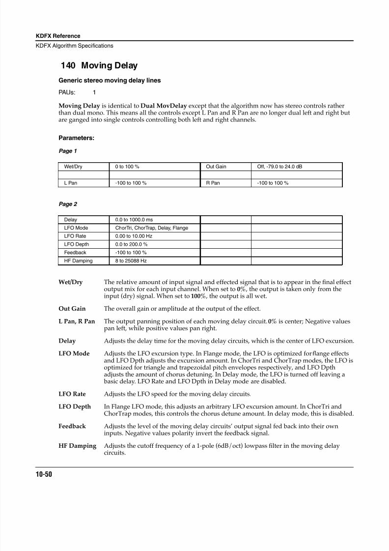
8/21/2019 MR_K2661
http://slidepdf.com/reader/full/mrk2661 132/499
10-50
KDFX Reference
KDFX Algorithm Specifications
140 Moving Delay
Generic stereo moving delay lines
PAUs: 1
Moving Delay is identical to Dual MovDelay except that the algorithm now has stereo controls ratherthan dual mono. This means all the controls except L Pan and R Pan are no longer dual left and right butare ganged into single controls controlling both left and right channels.
Parameters:
Page 1
Page 2
Wet/Dry The relative amount of input signal and effected signal that is to appear in the final effect
output mix for each input channel. When set to 0% , the output is taken only from theinput (dry) signal. When set to 100% , the output is all wet.
Out Gain The overall gain or amplitude at the output of the effect.
L Pan, R Pan The output panning position of each moving delay circuit. 0% is center; Negative valuespan left, while positive values pan right.
Delay Adjusts the delay time for the moving delay circuits, which is the center of LFO excursion.
LFO Mode Adjusts the LFO excursion type. In Flange mode, the LFO is optimized for flange effectsand LFO Dpth adjusts the excursion amount. In ChorTri and ChorTrap modes, the LFO isoptimized for triangle and trapezoidal pitch envelopes respectively, and LFO Dpthadjusts the amount of chorus detuning. In Delay mode, the LFO is turned off leaving a basic delay. LFO Rate and LFO Dpth in Delay mode are disabled.
LFO Rate Adjusts the LFO speed for the moving delay circuits.
LFO Depth In Flange LFO mode, this adjusts an arbitrary LFO excursion amount. In ChorTri andChorTrap modes, this controls the chorus detune amount. In delay mode, this is disabled.
Feedback Adjusts the level of the moving delay circuits’ output signal fed back into their owninputs. Negative values polarity invert the feedback signal.
HF Damping Adjusts the cutoff frequency of a 1-pole (6dB/oct) lowpass filter in the moving delaycircuits.
Wet/Dry 0 to 100 % Out Gain Off, -79.0 to 24.0 dB
L Pan -100 to 100 % R Pan -100 to 100 %
Delay 0.0 to 1000.0 ms
LFO Mode ChorTri, ChorTrap, Delay, Flange
LFO Rate 0.00 to 10.00 Hz
LFO Depth 0.0 to 200.0 %
Feedback -100 to 100 %
HF Damping 8 to 25088 Hz
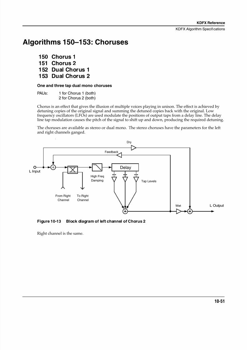
8/21/2019 MR_K2661
http://slidepdf.com/reader/full/mrk2661 133/499
KDFX Reference
KDFX Algorithm Specifications
10-51
Algorithms 150–153: Choruses
150 Chorus 1
151 Chorus 2152 Dual Chorus 1153 Dual Chorus 2
One and three tap dual mono choruses
PAUs: 1 for Chorus 1 (both)2 for Chorus 2 (both)
Chorus is an effect that gives the illusion of multiple voices playing in unison. The effect is achieved bydetuning copies of the original signal and summing the detuned copies back with the original. Lowfrequency oscillators (LFOs) are used modulate the positions of output taps from a delay line. The delayline tap modulation causes the pitch of the signal to shift up and down, producing the required detuning.
The choruses are available as stereo or dual mono. The stereo choruses have the parameters for the leftand right channels ganged.
F
Figure 10-13 Block diagram of left channel of Chorus 2
Right channel is the same.
Dry
Delay
Channel
From Right
Damping
Channel
To Right
High Freq
Feedback
Tap Levels
Wet
L Input
L Output
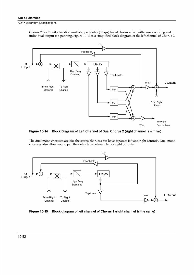
8/21/2019 MR_K2661
http://slidepdf.com/reader/full/mrk2661 134/499
10-52
KDFX Reference
KDFX Algorithm Specifications
Chorus 2 is a 2 unit allocation multi-tapped delay (3 taps) based chorus effect with cross-coupling andindividual output tap panning. Figure 10-13 is a simplified block diagram of the left channel of Chorus 2.
Figure 10-14 Block Diagram of Left Channel of Dual Chorus 2 (right channel is similar)
The dual mono choruses are like the stereo choruses but have separate left and right controls. Dual mono
choruses also allow you to pan the delay taps between left or right outputs
Figure 10-15 Block diagram of left channel of Chorus 1 (right channel is the same)
Dry
Delay
Channel
From Right
Damping
Channel
To Right
High Freq
Feedback
From Right
Tap Levels
Pan
Pan
Pan
Wet
Wet
Output Sum
To Right
Pans
L Input
L Output
From Right
Channel
To Right
Channel
Dry
Feedback
Tap LevelWet
High Freq
Damping
DelayL Input
L Output
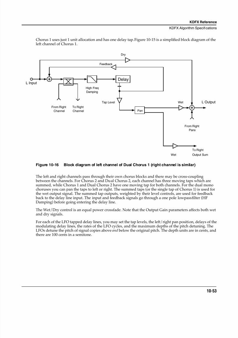
8/21/2019 MR_K2661
http://slidepdf.com/reader/full/mrk2661 135/499
KDFX Reference
KDFX Algorithm Specifications
10-53
Chorus 1 uses just 1 unit allocation and has one delay tap. Figure 10-15 is a simplified block diagram of theleft channel of Chorus 1.
Figure 10-16 Block diagram of left channel of Dual Chorus 1 (right channel is similar)
The left and right channels pass through their own chorus blocks and there may be cross-coupling between the channels. For Chorus 2 and Dual Chorus 2, each channel has three moving taps which aresummed, while Chorus 1 and Dual Chorus 2 have one moving tap for both channels. For the dual monochoruses you can pan the taps to left or right. The summed taps (or the single tap of Chorus 1) is used forthe wet output signal. The summed tap outputs, weighted by their level controls, are used for feedback back to the delay line input. The input and feedback signals go through a one pole lowpass filter (HFDamping) before going entering the delay line.
The Wet/Dry control is an equal power crossfade. Note that the Output Gain parameters affects both wetand dry signals.
For each of the LFO tapped delay lines, you may set the tap levels, the left/right pan position, delays of themodulating delay lines, the rates of the LFO cycles, and the maximum depths of the pitch detuning. TheLFOs detune the pitch of signal copies above and below the original pitch. The depth units are in cents, and
there are 100 cents in a semitone.
From Right
Channel
To Right
Channel
Dry
Feedback
Tap Level Wet
Wet
From Right
Pans
To Right
Output Sum
High Freq
Damping
Delay
Pan
L Input
L Output
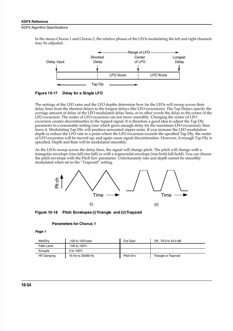
8/21/2019 MR_K2661
http://slidepdf.com/reader/full/mrk2661 136/499
10-54
KDFX Reference
KDFX Algorithm Specifications
In the stereo Chorus 1 and Chorus 2, the relative phases of the LFOs modulating the left and right channelsmay be adjusted.
Figure 10-17 Delay for a Single LFO
The settings of the LFO rates and the LFO depths determine how far the LFOs will sweep across theirdelay lines from the shortest delays to the longest delays (the LFO excursions). The Tap Delays specify theaverage amount of delay of the LFO modulated delay lines, or in other words the delay to the center of theLFO excursion. The center of LFO excursion can not move smoothly. Changing the center of LFOexcursion creates discontinuities in the tapped signal. It is therefore a good idea to adjust the Tap Dlyparameter to a reasonable setting (one which gives enough delay for the maximum LFO excursion), thenleave it. Modulating Tap Dly will produce unwanted zipper noise. If you increase the LFO modulationdepth or reduce the LFO rate to a point where the LFO excursion exceeds the specified Tap Dly, the centerof LFO excursion will be moved up, and again cause signal discontinuities. However, if enough Tap Dly isspecified, Depth and Rate will be modulated smoothly.
As the LFOs sweep across the delay lines, the signal will change pitch. The pitch will change with atriangular envelope (rise-fall-rise-fall) or with a trapezoidal envelope (rise-hold-fall-hold). You can choosethe pitch envelope with the Pitch Env parameter. Unfortunately rate and depth cannot be smoothlymodulated when set to the “Trapzoid” setting.
Figure 10-18 Pitch Envelopes (i) Triangle and (ii) Trapzoid
Parameters for Chorus 1
Page 1
Wet/Dry -100 to 100%wet Out Gain Off, -79.0 to 24.0 dB
Fdbk Level -100 to 100%
Xcouple 0 to 100%
HF Damping 16 Hz to 25088 Hz Pitch Env Triangle or Trapzoid
Tap Dly
Delay InputShortest
DelayLongest
DelayCenterof LFO
LFO Xcurs LFO Xcurs
Range of LFO
(i) (ii)
P i t
c h
Time Time
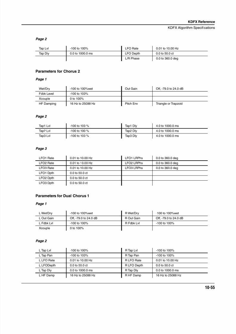
8/21/2019 MR_K2661
http://slidepdf.com/reader/full/mrk2661 137/499
KDFX Reference
KDFX Algorithm Specifications
10-55
Page 2
Parameters for Chorus 2
Page 1
Page 2
Page 3
Parameters for Dual Chorus 1
Page 1
Page 2
Tap Lvl -100 to 100% LFO Rate 0.01 to 10.00 Hz
Tap Dly 0.0 to 1000.0 ms LFO Depth 0.0 to 50.0 ct
L/R Phase 0.0 to 360.0 deg
Wet/Dry -100 to 100%wet Out Gain Off, -79.0 to 24.0 dB
Fdbk Level -100 to 100%
Xcouple 0 to 100%
HF Damping 16 Hz to 25088 Hz Pitch Env Triangle or Trapzoid
Tap1 Lvl -100 to 100 % Tap1 Dly 4.0 to 1000.0 ms
Tap2 Lvl -100 to 100 % Tap2 Dly 4.0 to 1000.0 ms
Tap3 Lvl -100 to 100 % Tap3 Dly 4.0 to 1000.0 ms
LFO1 Rate 0.01 to 10.00 Hz LFO1 LRPhs 0.0 to 360.0 deg
LFO2 Rate 0.01 to 10.00 Hz LFO2 LRPhs 0.0 to 360.0 deg
LFO3 Rate 0.01 to 10.00 Hz LFO3 LRPhs 0.0 to 360.0 deg
LFO1 Dpth 0.0 to 50.0 ct
LFO2 Dpth 0.0 to 50.0 ct
LFO3 Dpth 0.0 to 50.0 ct
L Wet/Dry -100 to 100%wet R Wet/Dry -100 to 100%wet
L Out Gain Off, -79.0 to 24.0 dB R Out Gain Off, -79.0 to 24.0 dB
L Fdbk Lvl -100 to 100% R Fdbk Lvl -100 to 100%
Xcouple 0 to 100%
L Tap Lvl -100 to 100% R Tap Lvl -100 to 100%
L Tap Pan -100 to 100% R Tap Pan -100 to 100%
L LFO Rate 0.01 to 10.00 Hz R LFO Rate 0.01 to 10.00 Hz
L LFODepth 0.0 to 50.0 ct R LFO Depth 0.0 to 50.0 ct
L Tap Dly 0.0 to 1000.0 ms R Tap Dly 0.0 to 1000.0 ms
L HF Damp 16 Hz to 25088 Hz R HF Damp 16 Hz to 25088 Hz
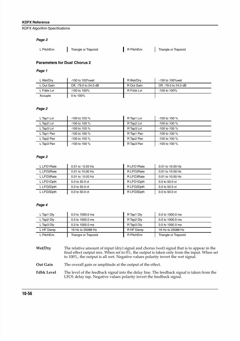
8/21/2019 MR_K2661
http://slidepdf.com/reader/full/mrk2661 138/499
10-56
KDFX Reference
KDFX Algorithm Specifications
Page 3
Parameters for Dual Chorus 2
Page 1
Page 2
Page 3
Page 4
Wet/Dry The relative amount of input (dry) signal and chorus (wet) signal that is to appear in thefinal effect output mix. When set to 0%, the output is taken only from the input. When setto 100%, the output is all wet. Negative values polarity invert the wet signal.
Out Gain The overall gain or amplitude at the output of the effect.
Fdbk Level The level of the feedback signal into the delay line. The feedback signal is taken from theLFO1 delay tap. Negative values polarity invert the feedback signal.
L PitchEnv Triangle or Trapzoid R PitchEnv Triangle or Trapzoid
L Wet/Dry -100 to 100%wet R Wet/Dry -100 to 100%wet
L Out Gain Off, -79.0 to 24.0 dB R Out Gain Off, -79.0 to 24.0 dB
L Fdbk Lvl -100 to 100% R Fdbk Lvl -100 to 100%
Xcouple 0 to 100%
L Tap1 Lvl -100 to 100 % R Tap1 Lvl -100 to 100 %L Tap2 Lvl -100 to 100 % R Tap2 Lvl -100 to 100 %
L Tap3 Lvl -100 to 100 % R Tap3 Lvl -100 to 100 %
L Tap1 Pan -100 to 100 % R Tap1 Pan -100 to 100 %
L Tap2 Pan -100 to 100 % R Tap2 Pan -100 to 100 %
L Tap3 Pan -100 to 100 % R Tap3 Pan -100 to 100 %
L LFO1Rate 0.01 to 10.00 Hz R LFO1Rate 0.01 to 10.00 Hz
L LFO2Rate 0.01 to 10.00 Hz R LFO2Rate 0.01 to 10.00 Hz
L LFO3Rate 0.01 to 10.00 Hz R LFO3Rate 0.01 to 10.00 Hz
L LFO1Dpth 0.0 to 50.0 ct R LFO1Dpth 0.0 to 50.0 ct
L LFO2Dpth 0.0 to 50.0 ct R LFO2Dpth 0.0 to 50.0 ct
L LFO3Dpth 0.0 to 50.0 ct R LFO3Dpth 0.0 to 50.0 ct
L Tap1 Dly 0.0 to 1000.0 ms R Tap1 Dly 0.0 to 1000.0 ms
L Tap2 Dly 0.0 to 1000.0 ms R Tap2 Dly 0.0 to 1000.0 ms
L Tap3 Dly 0.0 to 1000.0 ms R Tap3 Dly 0.0 to 1000.0 ms
L HF Damp 16 Hz to 25088 Hz R HF Damp 16 Hz to 25088 Hz
L PitchEnv Triangle or Trapzoid R PitchEnv Triangle or Trapzoid
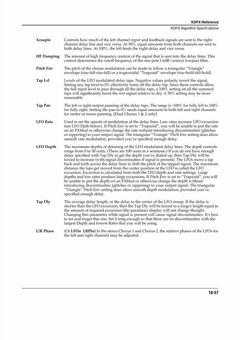
8/21/2019 MR_K2661
http://slidepdf.com/reader/full/mrk2661 139/499
KDFX Reference
KDFX Algorithm Specifications
10-57
Xcouple Controls how much of the left channel input and feedback signals are sent to the rightchannel delay line and vice versa. At 50%, equal amounts from both channels are sent to both delay lines. At 100%, the left feeds the right delay and vice versa.
HF Damping The amount of high frequency content of the signal that is sent into the delay lines. Thiscontrol determines the cutoff frequency of the one-pole (-6dB/octave) lowpass filter.
Pitch Env The pitch of the chorus modulation can be made to follow a triangular “Triangle”envelope (rise-fall-rise-fall) or a trapezoidal “Trapzoid” envelope (rise-hold-fall-hold).
Tap Lvl Levels of the LFO modulated delay taps. Negative values polarity invert the signal.Setting any tap level to 0% effectively turns off the delay tap. Since these controls allowthe full input level to pass through all the delay taps, a 100% setting on all the summedtaps will significantly boost the wet signal relative to dry. A 50% setting may be morereasonable.
Tap Pan The left or right output panning of the delay taps. The range is -100% for fully left to 100%for fully right. Setting the pan to 0% sends equal amounts to both left and right channelsfor center or mono panning. [Dual Chorus 1 & 2 only]
LFO Rate Used to set the speeds of modulation of the delay lines. Low rates increase LFO excursion(see LFO Dpth below). If Pitch Env is set to “Trapzoid”, you will be unable to put the rateon an FXMod or otherwise change the rate without introducing discontinuities (glitchesor zippering) to your output signal. The triangular “Triangle” Pitch Env setting does allowsmooth rate modulation, provided you’ve specified enough delay.
LFO Depth The maximum depths of detuning of the LFO modulated delay lines. The depth controlsrange from 0 to 50 cents. (There are 100 cents in a semitone.) If you do not have enoughdelay specified with Tap Dly to get the depth you’ve dialed up, then Tap Dly will beforced to increase (with signal disconinuities if signal is present). The LFOs move a tap back and forth across the delay lines to shift the pitch of the tapped signal. The maximumdistance the taps get moved from the center position of the LFO is called the LFOexcursion. Excursion is calculated from both the LFO depth and rate settings. Large
depths and low rates produce large excursions. If Pitch Env is set to “Trapzoid”, you will be unable to put the depth on an FXMod or otherwise change the depth withoutintroducing discontinuities (glitches or zippering) to your output signal. The triangular“Triangle” Pitch Env setting does allow smooth depth modulation, provided you’vespecified enough delay.
Tap Dly The average delay length, or the delay to the center of the LFO sweep. If the delay isshorter than the LFO excursion, then the Tap Dly will be forced to a longer length equal tothe amount of required excursion (the parameter display will not change though).Changing this parameter while signal is present will cause signal discontinuities. It’s bestto set and forget this one. Set it long enough so that there are no discontinuities with thelargest Depth and lowest Rates that you will be using.
L/R Phase (Or LFOn LRPhs) In the stereo Chorus 1 and Chorus 2, the relative phases of the LFOs forthe left and right channels may be adjusted.
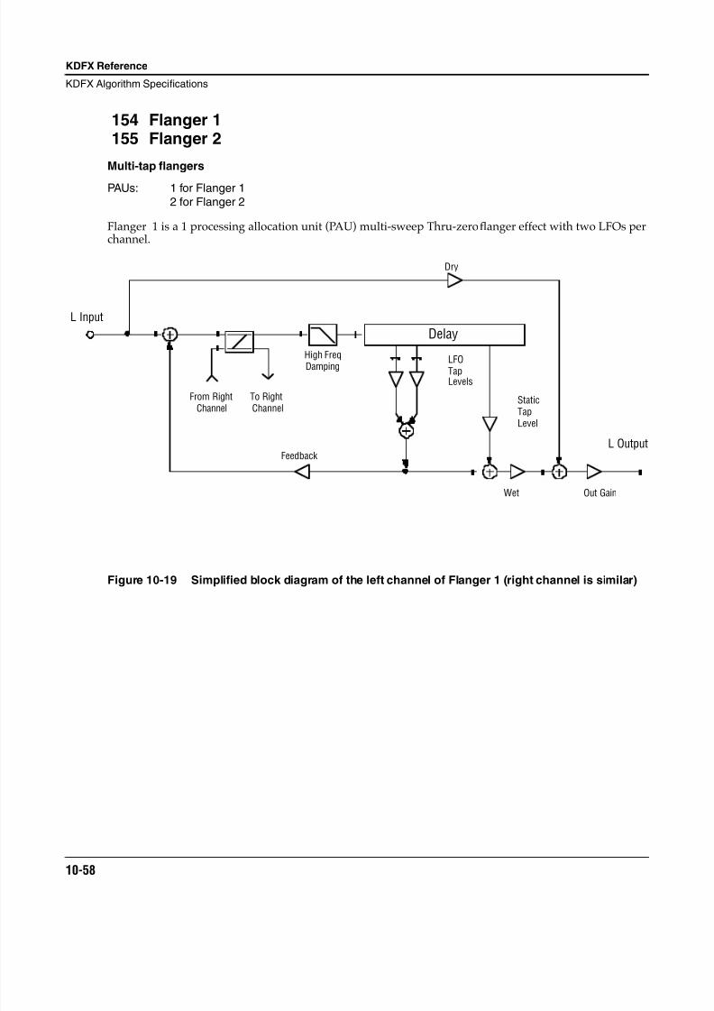
8/21/2019 MR_K2661
http://slidepdf.com/reader/full/mrk2661 140/499
10-58
KDFX Reference
KDFX Algorithm Specifications
154 Flanger 1155 Flanger 2
Multi-tap flangers
PAUs: 1 for Flanger 12 for Flanger 2
Flanger 1 is a 1 processing allocation unit (PAU) multi-sweep Thru-zero flanger effect with two LFOs perchannel.
Figure 10-19 Simplified block diagram of the left channel of Flanger 1 (right channel is similar)
L Input
L Output
Dry
Wet
High FreqDamping
From RightChannel
To RightChannel
Delay
StaticTapLevel
LFOTapLevels
Out Gain
Feedback
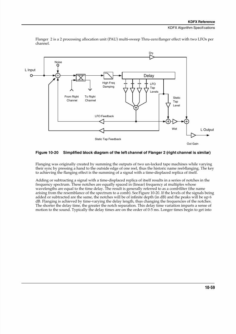
8/21/2019 MR_K2661
http://slidepdf.com/reader/full/mrk2661 141/499
KDFX Reference
KDFX Algorithm Specifications
10-59
Flanger 2 is a 2 processing allocation unit (PAU) multi-sweep Thru-zero flanger effect with two LFOs perchannel.
Figure 10-20 Simplified block diagram of the left channel of Flanger 2 (right channel is similar)
Flanging was originally created by summing the outputs of two un-locked tape machines while varyingtheir sync by pressing a hand to the outside edge of one reel, thus the historic name reel-flanging. The keyto achieving the flanging effect is the summing of a signal with a time-displaced replica of itself.
Adding or subtracting a signal with a time-displaced replica of itself results in a series of notches in thefrequency spectrum. These notches are equally spaced in (linear) frequency at multiples whosewavelengths are equal to the time delay. The result is generally referred to as a comb filter (the namearising from the resemblance of the spectrum to a comb). See Figure 10-20. If the levels of the signals beingadded or subtracted are the same, the notches will be of infinite depth (in dB) and the peaks will be up 6dB. Flanging is achieved by time-varying the delay length, thus changing the frequencies of the notches.The shorter the delay time, the greater the notch separation. This delay time variation imparts a sense ofmotion to the sound. Typically the delay times are on the order of 0-5 ms. Longer times begin to get into
L Input
L Output
Dry
Wet
High Freq
Damping
From Right
Channel
To Right
Channel
Delay
Static
Tap
Level
LFO
Tap
Levels
Out Gain
Noise
LFO Feedback
Static Tap Feedback
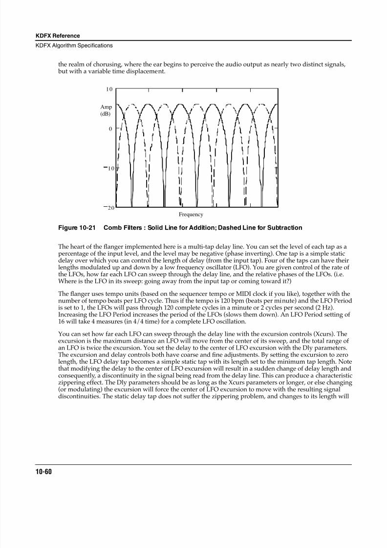
8/21/2019 MR_K2661
http://slidepdf.com/reader/full/mrk2661 142/499
10-60
KDFX Reference
KDFX Algorithm Specifications
the realm of chorusing, where the ear begins to perceive the audio output as nearly two distinct signals, but with a variable time displacement.
Figure 10-21 Comb Filters : Solid Line for Addition; Dashed Line for Subtraction
The heart of the flanger implemented here is a multi-tap delay line. You can set the level of each tap as apercentage of the input level, and the level may be negative (phase inverting). One tap is a simple staticdelay over which you can control the length of delay (from the input tap). Four of the taps can have theirlengths modulated up and down by a low frequency oscillator (LFO). You are given control of the rate ofthe LFOs, how far each LFO can sweep through the delay line, and the relative phases of the LFOs. (i.e.Where is the LFO in its sweep: going away from the input tap or coming toward it?)
The flanger uses tempo units (based on the sequencer tempo or MIDI clock if you like), together with thenumber of tempo beats per LFO cycle. Thus if the tempo is 120 bpm (beats per minute) and the LFO Periodis set to 1, the LFOs will pass through 120 complete cycles in a minute or 2 cycles per second (2 Hz).Increasing the LFO Period increases the period of the LFOs (slows them down). An LFO Period setting of16 will take 4 measures (in 4/4 time) for a complete LFO oscillation.
You can set how far each LFO can sweep through the delay line with the excursion controls (Xcurs). Theexcursion is the maximum distance an LFO will move from the center of its sweep, and the total range ofan LFO is twice the excursion. You set the delay to the center of LFO excursion with the Dly parameters.The excursion and delay controls both have coarse and fine adjustments. By setting the excursion to zerolength, the LFO delay tap becomes a simple static tap with its length set to the minimum tap length. Notethat modifying the delay to the center of LFO excursion will result in a sudden change of delay length andconsequently, a discontinuity in the signal being read from the delay line. This can produce a characteristic
zippering effect. The Dly parameters should be as long as the Xcurs parameters or longer, or else changing(or modulating) the excursion will force the center of LFO excursion to move with the resulting signaldiscontinuities. The static delay tap does not suffer the zippering problem, and changes to its length will
10
0
10
20
Amp
(dB)
Frequency
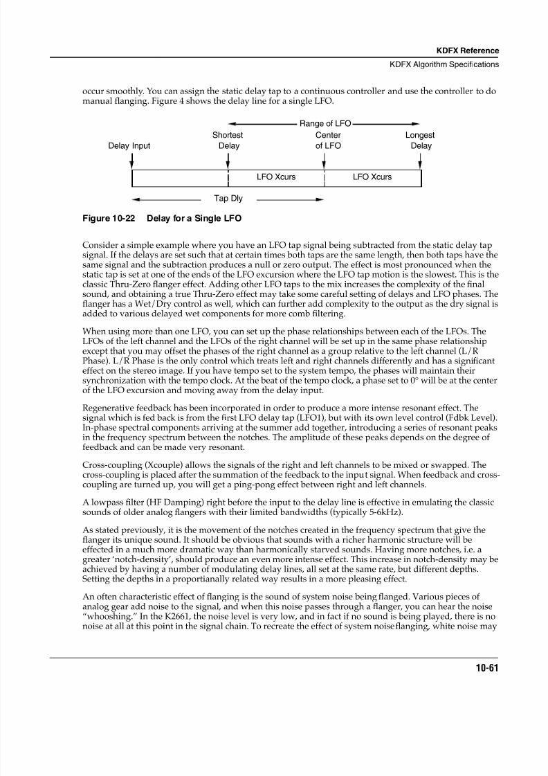
8/21/2019 MR_K2661
http://slidepdf.com/reader/full/mrk2661 143/499
KDFX Reference
KDFX Algorithm Specifications
10-61
occur smoothly. You can assign the static delay tap to a continuous controller and use the controller to domanual flanging. Figure 4 shows the delay line for a single LFO.
Figure 10-22 Delay for a Single LFO
Consider a simple example where you have an LFO tap signal being subtracted from the static delay tapsignal. If the delays are set such that at certain times both taps are the same length, then both taps have thesame signal and the subtraction produces a null or zero output. The effect is most pronounced when thestatic tap is set at one of the ends of the LFO excursion where the LFO tap motion is the slowest. This is theclassic Thru-Zero flanger effect. Adding other LFO taps to the mix increases the complexity of the finalsound, and obtaining a true Thru-Zero effect may take some careful setting of delays and LFO phases. Theflanger has a Wet/Dry control as well, which can further add complexity to the output as the dry signal isadded to various delayed wet components for more comb filtering.
When using more than one LFO, you can set up the phase relationships between each of the LFOs. TheLFOs of the left channel and the LFOs of the right channel will be set up in the same phase relationshipexcept that you may offset the phases of the right channel as a group relative to the left channel (L/RPhase). L/R Phase is the only control which treats left and right channels differently and has a significanteffect on the stereo image. If you have tempo set to the system tempo, the phases will maintain theirsynchronization with the tempo clock. At the beat of the tempo clock, a phase set to 0° will be at the centerof the LFO excursion and moving away from the delay input.
Regenerative feedback has been incorporated in order to produce a more intense resonant effect. Thesignal which is fed back is from the first LFO delay tap (LFO1), but with its own level control (Fdbk Level).In-phase spectral components arriving at the summer add together, introducing a series of resonant peaksin the frequency spectrum between the notches. The amplitude of these peaks depends on the degree offeedback and can be made very resonant.
Cross-coupling (Xcouple) allows the signals of the right and left channels to be mixed or swapped. Thecross-coupling is placed after the summation of the feedback to the input signal. When feedback and cross-coupling are turned up, you will get a ping-pong effect between right and left channels.
A lowpass filter (HF Damping) right before the input to the delay line is effective in emulating the classicsounds of older analog flangers with their limited bandwidths (typically 5-6kHz).
As stated previously, it is the movement of the notches created in the frequency spectrum that give thefl
anger its unique sound. It should be obvious that sounds with a richer harmonic structure will beeffected in a much more dramatic way than harmonically starved sounds. Having more notches, i.e. agreater ‘notch-density’, should produce an even more intense effect. This increase in notch-density may beachieved by having a number of modulating delay lines, all set at the same rate, but different depths.Setting the depths in a proportianally related way results in a more pleasing effect.
An often characteristic effect of flanging is the sound of system noise being flanged. Various pieces ofanalog gear add noise to the signal, and when this noise passes through a flanger, you can hear the noise“whooshing.” In the K2661, the noise level is very low, and in fact if no sound is being played, there is nonoise at all at this point in the signal chain. To recreate the effect of system noise flanging, white noise may
Tap Dly
Delay InputShortest
DelayLongest
DelayCenterof LFO
LFO Xcurs LFO Xcurs
Range of LFO
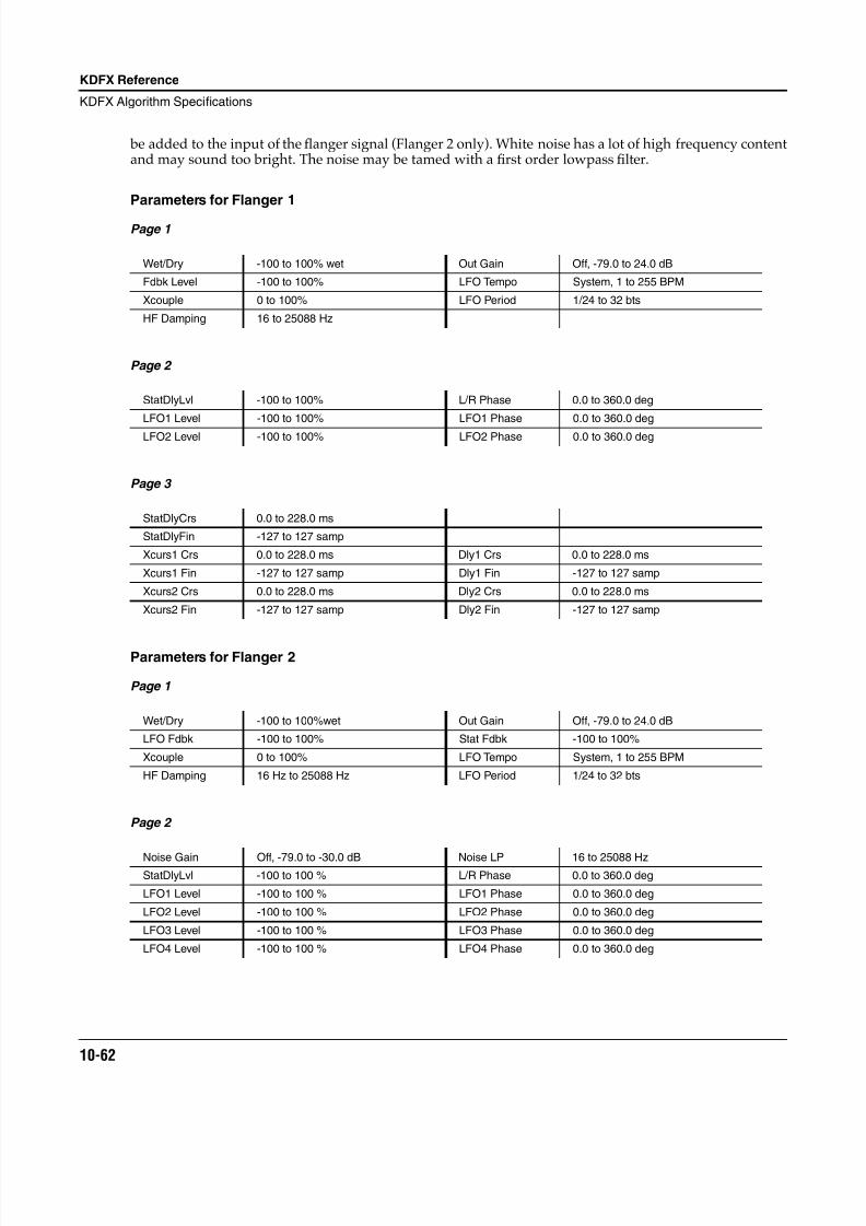
8/21/2019 MR_K2661
http://slidepdf.com/reader/full/mrk2661 144/499
10-62
KDFX Reference
KDFX Algorithm Specifications
be added to the input of the flanger signal (Flanger 2 only). White noise has a lot of high frequency contentand may sound too bright. The noise may be tamed with a first order lowpass filter.
Parameters for Flanger 1
Page 1
Page 2
Page 3
Parameters for Flanger 2
Page 1
Page 2
Wet/Dry -100 to 100% wet Out Gain Off, -79.0 to 24.0 dB
Fdbk Level -100 to 100% LFO Tempo System, 1 to 255 BPM
Xcouple 0 to 100% LFO Period 1/24 to 32 bts
HF Damping 16 to 25088 Hz
StatDlyLvl -100 to 100% L/R Phase 0.0 to 360.0 deg
LFO1 Level -100 to 100% LFO1 Phase 0.0 to 360.0 deg
LFO2 Level -100 to 100% LFO2 Phase 0.0 to 360.0 deg
StatDlyCrs 0.0 to 228.0 ms
StatDlyFin -127 to 127 samp
Xcurs1 Crs 0.0 to 228.0 ms Dly1 Crs 0.0 to 228.0 ms
Xcurs1 Fin -127 to 127 samp Dly1 Fin -127 to 127 samp
Xcurs2 Crs 0.0 to 228.0 ms Dly2 Crs 0.0 to 228.0 ms
Xcurs2 Fin -127 to 127 samp Dly2 Fin -127 to 127 samp
Wet/Dry -100 to 100%wet Out Gain Off, -79.0 to 24.0 dB
LFO Fdbk -100 to 100% Stat Fdbk -100 to 100%
Xcouple 0 to 100% LFO Tempo System, 1 to 255 BPM
HF Damping 16 Hz to 25088 Hz LFO Period 1/24 to 32 bts
Noise Gain Off, -79.0 to -30.0 dB Noise LP 16 to 25088 HzStatDlyLvl -100 to 100 % L/R Phase 0.0 to 360.0 deg
LFO1 Level -100 to 100 % LFO1 Phase 0.0 to 360.0 deg
LFO2 Level -100 to 100 % LFO2 Phase 0.0 to 360.0 deg
LFO3 Level -100 to 100 % LFO3 Phase 0.0 to 360.0 deg
LFO4 Level -100 to 100 % LFO4 Phase 0.0 to 360.0 deg
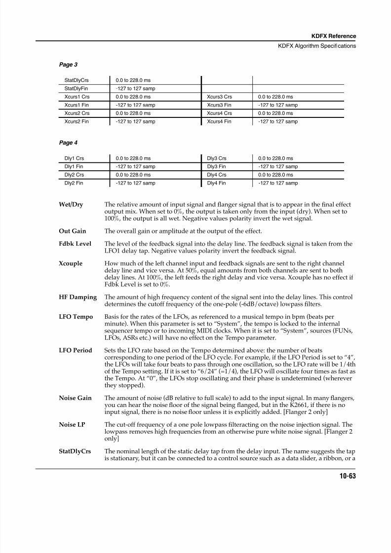
8/21/2019 MR_K2661
http://slidepdf.com/reader/full/mrk2661 145/499
KDFX Reference
KDFX Algorithm Specifications
10-63
Page 3
Page 4
Wet/Dry The relative amount of input signal and flanger signal that is to appear in the final effectoutput mix. When set to 0%, the output is taken only from the input (dry). When set to100%, the output is all wet. Negative values polarity invert the wet signal.
Out Gain The overall gain or amplitude at the output of the effect.
Fdbk Level The level of the feedback signal into the delay line. The feedback signal is taken from theLFO1 delay tap. Negative values polarity invert the feedback signal.
Xcouple How much of the left channel input and feedback signals are sent to the right channeldelay line and vice versa. At 50%, equal amounts from both channels are sent to bothdelay lines. At 100%, the left feeds the right delay and vice versa. Xcouple has no effect ifFdbk Level is set to 0%.
HF Damping The amount of high frequency content of the signal sent into the delay lines. This controldetermines the cutoff frequency of the one-pole (-6dB/octave) lowpass filters.
LFO Tempo Basis for the rates of the LFOs, as referenced to a musical tempo in bpm (beats perminute). When this parameter is set to “System”, the tempo is locked to the internalsequencer tempo or to incoming MIDI clocks. When it is set to “System”, sources (FUNs,LFOs, ASRs etc.) will have no effect on the Tempo parameter.
LFO Period Sets the LFO rate based on the Tempo determined above: the number of beatscorresponding to one period of the LFO cycle. For example, if the LFO Period is set to “4”,the LFOs will take four beats to pass through one oscillation, so the LFO rate will be 1/4thof the Tempo setting. If it is set to “6/24” (=1/4), the LFO will oscillate four times as fast asthe Tempo. At “0”, the LFOs stop oscillating and their phase is undetermined (wherever
they stopped).Noise Gain The amount of noise (dB relative to full scale) to add to the input signal. In many flangers,
you can hear the noise floor of the signal being flanged, but in the K2661, if there is noinput signal, there is no noise floor unless it is explicitly added. [Flanger 2 only]
Noise LP The cut-off frequency of a one pole lowpass filteracting on the noise injection signal. Thelowpass removes high frequencies from an otherwise pure white noise signal. [Flanger 2only]
StatDlyCrs The nominal length of the static delay tap from the delay input. The name suggests the tapis stationary, but it can be connected to a control source such as a data slider, a ribbon, or a
StatDlyCrs 0.0 to 228.0 ms
StatDlyFin -127 to 127 samp
Xcurs1 Crs 0.0 to 228.0 ms Xcurs3 Crs 0.0 to 228.0 msXcurs1 Fin -127 to 127 samp Xcurs3 Fin -127 to 127 samp
Xcurs2 Crs 0.0 to 228.0 ms Xcurs4 Crs 0.0 to 228.0 ms
Xcurs2 Fin -127 to 127 samp Xcurs4 Fin -127 to 127 samp
Dly1 Crs 0.0 to 228.0 ms Dly3 Crs 0.0 to 228.0 ms
Dly1 Fin -127 to 127 samp Dly3 Fin -127 to 127 samp
Dly2 Crs 0.0 to 228.0 ms Dly4 Crs 0.0 to 228.0 ms
Dly2 Fin -127 to 127 samp Dly4 Fin -127 to 127 samp
8/21/2019 MR_K2661
http://slidepdf.com/reader/full/mrk2661 146/499
10-64
KDFX Reference
KDFX Algorithm Specifications
VAST function to smoothly vary the delay length. The range for all delays and excursionsis 0 to 230 ms, but for flanging the range 0 to 5 ms is most effective.
StatDlyFin A fine adjustment to the static delay tap length. The resolution is one sample.
StatDlyLvl The level of the static delay tap. Negative values polarity invert the signal. Setting any taplevel to 0% turns off the delay tap.
Xcurs n Crs The LFO excursion controls set how far the LFO modulated delay taps can move from thecenter of their ranges. The total range of the LFO sweep is twice the excursion. If theexcursion is set to 0, the LFO does not move and the tap behaves like a simple delay lineset to the minimum delay. The excursion cannot be made longer than than the delay to thecenter of excursion (see Dly Crs & Dly Fin below) because delays cannot be made shorterthan 0. If you attempt longer excursions, the length of the Dly Crs/Fin will be forced toincrease (though you will not see the increased length displayed in the Dly Crs/Finparameters). The range for all delays and excursions is 0 to 230 ms, but for flanging therange 0 to 5 ms is most effective. This parameter is a coarse adjustment for the excursion.
Xcurs n Fin A fine adjustment for the LFO excursions. The resolution is one sample.
Dly n Crs The delay to the center of LFO tap range. The maximum delay will be this delay plus theLFO excursion delay. The minimum delay will be this delay minus the LFO excursiondelay. Since delays cannot be less than 0 ms in length, the this delay length will beincreased if LFO excursion is larger than this delay length. The range for all delays andexcursions is 0 to 230 ms, but for flanging the range 0 to 5 ms is most effective. Thisparameter is a coarse adjustment for the delay.
Dly n Fin A fine adjustment to the minimum delay tap lengths. The resolution is one sample.
LFOn Level The levels of the LFO modulated delay taps. Negative values polarity invert the signal.Setting any tap level to 0% turns off the delay tap.
LFOn Phase The phase angles of the LFOs relative to each other and to the system tempo clock, ifturned on (see Tempo). For example, if one LFO is set to 0° and another is set to 180°, then
when one LFO delay tap is at its shortest, the other will be at its longest. If the systemtempo clock is on, the LFOs are synchronized to the clock with absolute phase. A phase of0° will put an LFO tap at the center of its range and its lengthening.
L/R Phase Adds the specified phase angle to the right channel LFOs. In all other respects the rightand left channels are symmetric. By moving this control away from 0°, the stereo soundfield is broken up and a stereo image becomes dif ficult to spatially locate. The effect isusually described as “phasey.” It tends to impart a greater sense of motion.
8/21/2019 MR_K2661
http://slidepdf.com/reader/full/mrk2661 147/499
KDFX Reference
KDFX Algorithm Specifications
10-65
Algorithms 156–160: Phasers
156 LFO Phaser
157 LFO Phaser Twin158 Manual Phaser159 Vibrato Phaser160 SingleLFO Phaser
A variety of single notch/bandpass Phasers
PAUs: 1 each
A simple phaser is an algorithm which produces an vague swishing or phasey effect. When the phasersignal is combined with the dry input signal or the phaser is fed back on itself, peaks and/or notches can be produced in the filter response making the effect much more pronounced. Most of the phaser
algorithms presented here have built in low frequency oscillators (LFOs) to generate the motion of thephasers. In the case of Manual Phaser, the phaser motion is left to you.
A phaser uses a special filter called an allpass filter to modify the phase response of a signal’s spectrumwithout changing the amplitude of the spectrum. Okay, that was a bit of a mouthful — so what does itmean? As the term “allpass filter” suggests, the filter by itself does not change the amplitude response of asignal passing through it. An allpass filter does not cut or boost any frequencies. An allpass filter doescause some frequencies to be delayed a little in time, and this small time shift is also known as a phasechange. The frequency where the phase change has its greatest effect is a parameter that you can control.By modulating the frequency of the phaser, you get the swishy phaser sound. With a modulation rate ofaround 6 Hz, an effect similar to vibrato may be obtained, but only in a limited range of filter frequencies.
By adding the phaser output to the dry input using, for example, a Wet/Dry parameter, you can producedpeaks and notches in the frequency response. At frequencies where the phaser is “in phase” with the drysignal, the signal level doubles (or there is a 6 dB level increase approximately). At frequencies where thephaser and dry signals are “out of phase”, the two signals cancel each other out and there is a notch in thefrequency response. You can get a complete notch when Wet/Dry is set to 50%. If subtraction is used
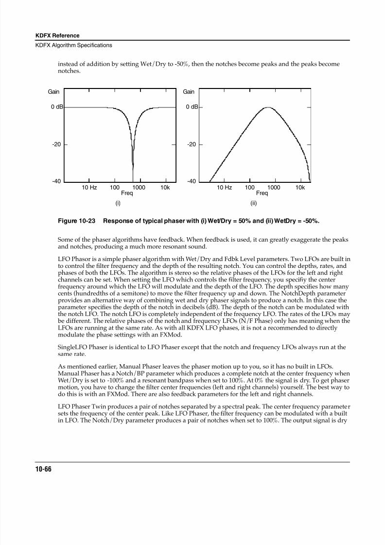
8/21/2019 MR_K2661
http://slidepdf.com/reader/full/mrk2661 148/499
10-66
KDFX Reference
KDFX Algorithm Specifications
instead of addition by setting Wet/Dry to -50%, then the notches become peaks and the peaks becomenotches.
Figure 10-23 Response of typical phaser with (i) Wet/Dry = 50% and (ii) WetDry = -50%.
Some of the phaser algorithms have feedback. When feedback is used, it can greatly exaggerate the peaksand notches, producing a much more resonant sound.
LFO Phasor is a simple phaser algorithm with Wet/Dry and Fdbk Level parameters. Two LFOs are built into control the filter frequency and the depth of the resulting notch. You can control the depths, rates, andphases of both the LFOs. The algorithm is stereo so the relative phases of the LFOs for the left and rightchannels can be set. When setting the LFO which controls the filter frequency, you specifiy the center
frequency around which the LFO will modulate and the depth of the LFO. The depth specifies how manycents (hundredths of a semitone) to move the filter frequency up and down. The NotchDepth parameterprovides an alternative way of combining wet and dry phaser signals to produce a notch. In this case theparameter specifies the depth of the notch in decibels (dB). The depth of the notch can be modulated withthe notch LFO. The notch LFO is completely independent of the frequency LFO. The rates of the LFOs may be different. The relative phases of the notch and frequency LFOs (N/F Phase) only has meaning when theLFOs are running at the same rate. As with all KDFX LFO phases, it is not a recommended to directlymodulate the phase settings with an FXMod.
SingleLFO Phaser is identical to LFO Phaser except that the notch and frequency LFOs always run at thesame rate.
As mentioned earlier, Manual Phaser leaves the phaser motion up to you, so it has no built in LFOs.Manual Phaser has a Notch/BP parameter which produces a complete notch at the center frequency when
Wet/Dry is set to -100% and a resonant bandpass when set to 100%. At 0% the signal is dry. To get phasermotion, you have to change the filter center frequencies (left and right channels) yourself. The best way todo this is with an FXMod. There are also feedback parameters for the left and right channels.
LFO Phaser Twin produces a pair of notches separated by a spectral peak. The center frequency parametersets the frequency of the center peak. Like LFO Phaser, the filter frequency can be modulated with a builtin LFO. The Notch/Dry parameter produces a pair of notches when set to 100%. The output signal is dry
0 dB
-20
-40
Freq10 Hz 100 1000 10k
Gain
0 dB
-20
-40
Freq10 Hz 100 1000 10k
Gain
(i) (ii)
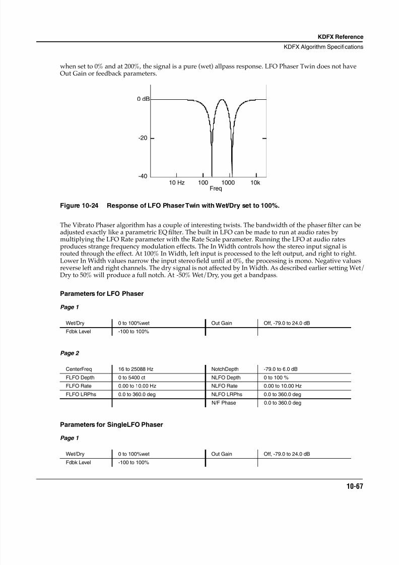
8/21/2019 MR_K2661
http://slidepdf.com/reader/full/mrk2661 149/499
KDFX Reference
KDFX Algorithm Specifications
10-67
when set to 0% and at 200%, the signal is a pure (wet) allpass response. LFO Phaser Twin does not haveOut Gain or feedback parameters.
Figure 10-24 Response of LFO Phaser Twin with Wet/Dry set to 100%.
The Vibrato Phaser algorithm has a couple of interesting twists. The bandwidth of the phaser filter can beadjusted exactly like a parametric EQ filter. The built in LFO can be made to run at audio rates bymultiplying the LFO Rate parameter with the Rate Scale parameter. Running the LFO at audio ratesproduces strange frequency modulation effects. The In Width controls how the stereo input signal isrouted through the effect. At 100% In Width, left input is processed to the left output, and right to right.Lower In Width values narrow the input stereo field until at 0%, the processing is mono. Negative valuesreverse left and right channels. The dry signal is not affected by In Width. As described earlier setting Wet/Dry to 50% will produce a full notch. At -50% Wet/Dry, you get a bandpass.
Parameters for LFO PhaserPage 1
Page 2
Parameters for SingleLFO Phaser
Page 1
Wet/Dry 0 to 100%wet Out Gain Off, -79.0 to 24.0 dB
Fdbk Level -100 to 100%
CenterFreq 16 to 25088 Hz NotchDepth -79.0 to 6.0 dB
FLFO Depth 0 to 5400 ct NLFO Depth 0 to 100 %
FLFO Rate 0.00 to 10.00 Hz NLFO Rate 0.00 to 10.00 Hz
FLFO LRPhs 0.0 to 360.0 deg NLFO LRPhs 0.0 to 360.0 degN/F Phase 0.0 to 360.0 deg
Wet/Dry 0 to 100%wet Out Gain Off, -79.0 to 24.0 dB
Fdbk Level -100 to 100%
0 dB
-20
-40
Freq10 Hz 100 1000 10k
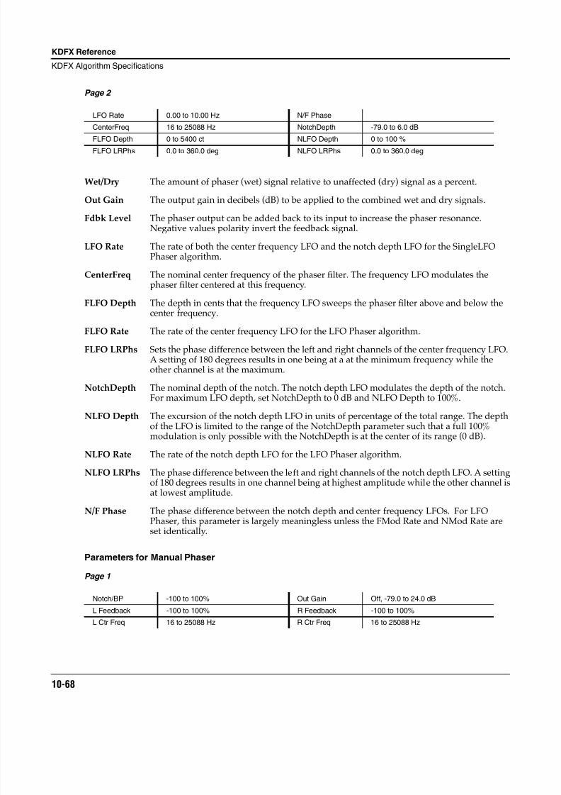
8/21/2019 MR_K2661
http://slidepdf.com/reader/full/mrk2661 150/499
10-68
KDFX Reference
KDFX Algorithm Specifications
Page 2
Wet/Dry The amount of phaser (wet) signal relative to unaffected (dry) signal as a percent.
Out Gain The output gain in decibels (dB) to be applied to the combined wet and dry signals.
Fdbk Level The phaser output can be added back to its input to increase the phaser resonance.Negative values polarity invert the feedback signal.
LFO Rate The rate of both the center frequency LFO and the notch depth LFO for the SingleLFOPhaser algorithm.
CenterFreq The nominal center frequency of the phaserfi
lter. The frequency LFO modulates thephaser filter centered at this frequency.
FLFO Depth The depth in cents that the frequency LFO sweeps the phaser filter above and below thecenter frequency.
FLFO Rate The rate of the center frequency LFO for the LFO Phaser algorithm.
FLFO LRPhs Sets the phase difference between the left and right channels of the center frequency LFO.A setting of 180 degrees results in one being at a at the minimum frequency while theother channel is at the maximum.
NotchDepth The nominal depth of the notch. The notch depth LFO modulates the depth of the notch.For maximum LFO depth, set NotchDepth to 0 dB and NLFO Depth to 100%.
NLFO Depth The excursion of the notch depth LFO in units of percentage of the total range. The depthof the LFO is limited to the range of the NotchDepth parameter such that a full 100%modulation is only possible with the NotchDepth is at the center of its range (0 dB).
NLFO Rate The rate of the notch depth LFO for the LFO Phaser algorithm.
NLFO LRPhs The phase difference between the left and right channels of the notch depth LFO. A settingof 180 degrees results in one channel being at highest amplitude while the other channel isat lowest amplitude.
N/F Phase The phase difference between the notch depth and center frequency LFOs. For LFOPhaser, this parameter is largely meaningless unless the FMod Rate and NMod Rate areset identically.
Parameters for Manual Phaser
Page 1
LFO Rate 0.00 to 10.00 Hz N/F Phase
CenterFreq 16 to 25088 Hz NotchDepth -79.0 to 6.0 dB
FLFO Depth 0 to 5400 ct NLFO Depth 0 to 100 %FLFO LRPhs 0.0 to 360.0 deg NLFO LRPhs 0.0 to 360.0 deg
Notch/BP -100 to 100% Out Gain Off, -79.0 to 24.0 dB
L Feedback -100 to 100% R Feedback -100 to 100%
L Ctr Freq 16 to 25088 Hz R Ctr Freq 16 to 25088 Hz
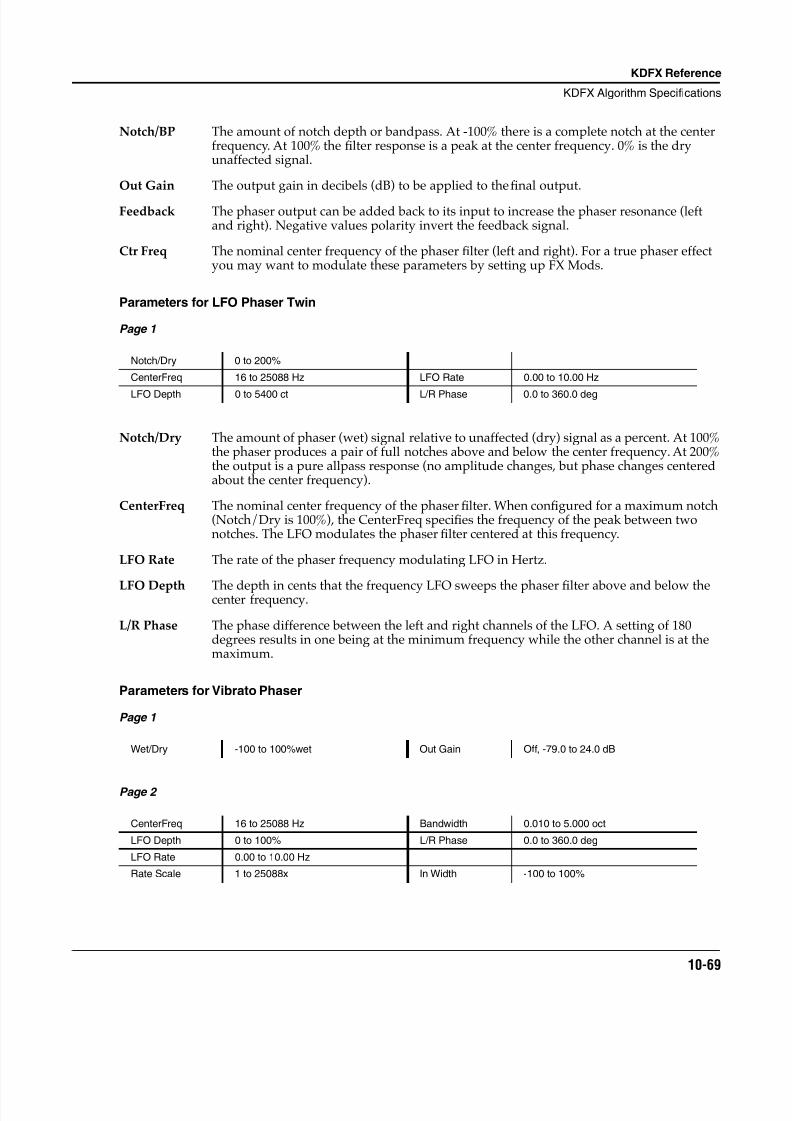
8/21/2019 MR_K2661
http://slidepdf.com/reader/full/mrk2661 151/499
KDFX Reference
KDFX Algorithm Specifications
10-69
Notch/BP The amount of notch depth or bandpass. At -100% there is a complete notch at the centerfrequency. At 100% the filter response is a peak at the center frequency. 0% is the dryunaffected signal.
Out Gain The output gain in decibels (dB) to be applied to the final output.
Feedback The phaser output can be added back to its input to increase the phaser resonance (leftand right). Negative values polarity invert the feedback signal.
Ctr Freq The nominal center frequency of the phaser filter (left and right). For a true phaser effectyou may want to modulate these parameters by setting up FX Mods.
Parameters for LFO Phaser Twin
Page 1
Notch/Dry The amount of phaser (wet) signal relative to unaffected (dry) signal as a percent. At 100%the phaser produces a pair of full notches above and below the center frequency. At 200%the output is a pure allpass response (no amplitude changes, but phase changes centeredabout the center frequency).
CenterFreq The nominal center frequency of the phaser filter. When configured for a maximum notch(Notch/Dry is 100%), the CenterFreq specifies the frequency of the peak between twonotches. The LFO modulates the phaser filter centered at this frequency.
LFO Rate The rate of the phaser frequency modulating LFO in Hertz.
LFO Depth The depth in cents that the frequency LFO sweeps the phaser filter above and below thecenter frequency.
L/R Phase The phase difference between the left and right channels of the LFO. A setting of 180degrees results in one being at the minimum frequency while the other channel is at themaximum.
Parameters for Vibrato Phaser
Page 1
Page 2
Notch/Dry 0 to 200%
CenterFreq 16 to 25088 Hz LFO Rate 0.00 to 10.00 Hz
LFO Depth 0 to 5400 ct L/R Phase 0.0 to 360.0 deg
Wet/Dry -100 to 100%wet Out Gain Off, -79.0 to 24.0 dB
CenterFreq 16 to 25088 Hz Bandwidth 0.010 to 5.000 oct
LFO Depth 0 to 100% L/R Phase 0.0 to 360.0 deg
LFO Rate 0.00 to 10.00 Hz
Rate Scale 1 to 25088x In Width -100 to 100%
8/21/2019 MR_K2661
http://slidepdf.com/reader/full/mrk2661 152/499
10-70
KDFX Reference
KDFX Algorithm Specifications
Wet/Dry The amount of phaser (wet) signal relative to unaffected (dry) signal as a percent. Whenset to 50% you get a complete notch. When set to -50%, the response is a bandpass filter.100% is a pure allpass filter (no amplitude changes, but a strong phase response).
Out Gain The output gain in decibels (dB) to be applied to the combined wet and dry signals.
CenterFreq The nominal center frequency of the phaser filter. The frequency LFO modulates thephaser filter centered at this frequency.
Bandwidth If the phaser is set to behave as a sweeping notch or bandpass, the bandwidth of the notchor bandpass is set with Bandwidth. This parameter works the same as for parametric EQfilter bandwidths.
LFO Depth The depth that the frequency LFO sweeps the phaser filter above and below the centerfrequency as a percent.
LFO Rate The rate of the LFO in Hertz. The LFO Rate may be scaled up by the Rate Scale parameter.
Rate Scale A rate multiplier value which may be used to increase the LFO frequency to audio rates.For example, if LFO Rate is set to 1.00 Hz and Rate Scale is set to 1047x, then the LFOfrequency is 1047 x 1.00 Hz = 1047 Hz.
L/R Phase Sets the phase difference between the left and right channels of the center frequency LFO.A setting of 180 degrees results in one being at a at the minimum frequency while theother channel is at the maximum.
In Width The width of the stereo field that passes through the stereo phaser filtering. Thisparameter does not affect the dry signal. When set to 100%, the left and right channels areprocessed to their respective outputs. Smaller values narrow the stereo image until at 0%the input channels are summed to mono and set to left and right outputs. Negative valuesinterchange the left and right channels.
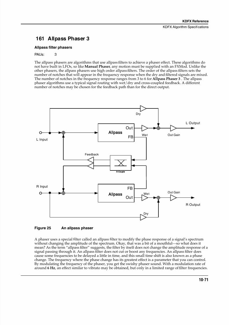
8/21/2019 MR_K2661
http://slidepdf.com/reader/full/mrk2661 153/499
KDFX Reference
KDFX Algorithm Specifications
10-71
161 Allpass Phaser 3
Allpass filter phasers
PAUs: 3
The allpass phasers are algorithms that use allpass filters to achieve a phaser effect. These algorithms donot have built in LFOs, so like Manual Phaser , any motion must be supplied with an FXMod. Unlike theother phasers, the allpass phasers use high order allpass filters. The order of the allpass filters sets thenumber of notches that will appear in the frequency response when the dry and filtered signals are mixed.The number of notches in the frequency response ranges from 3 to 6 for Allpass Phaser 3 . The allpassphaser algorithms use a typical signal routing with wet/dry and cross-coupled feedback. A differentnumber of notches may be chosen for the feedback path than for the direct output.
Figure 25 An allpass phaser
A phaser uses a special filter called an allpass filter to modify the phase response of a signal’s spectrumwithout changing the amplitude of the spectrum. Okay, that was a bit of a mouthful—so what does itmean? As the term “allpass filter” suggests, the filter by itself does not change the amplitude response of asignal passing through it. An allpass filter does not cut or boost any frequencies. An allpass filter doescause some frequencies to be delayed a little in time, and this small time shift is also known as a phasechange. The frequency where the phase change has its greatest effect is a parameter that you can control.By modulating the frequency of the phaser, you get the swishy phaser sound. With a modulation rate ofaround 6 Hz , an effect similar to vibrato may be obtained, but only in a limited range of filter frequencies.
X Couple
Feedback
Out
FB
Dry
Dry
Wet
Wetllpass
Allpass
L Input
R Input
L Output
R Output
Out Gain
Out Gain
Out
FB
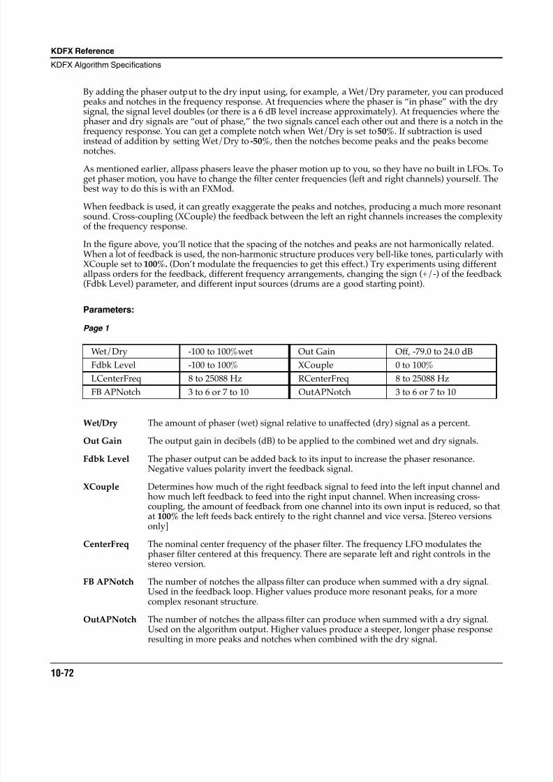
8/21/2019 MR_K2661
http://slidepdf.com/reader/full/mrk2661 154/499
10-72
KDFX Reference
KDFX Algorithm Specifications
By adding the phaser output to the dry input using, for example, a Wet/Dry parameter, you can producedpeaks and notches in the frequency response. At frequencies where the phaser is “in phase” with the drysignal, the signal level doubles (or there is a 6 dB level increase approximately). At frequencies where thephaser and dry signals are “out of phase,” the two signals cancel each other out and there is a notch in thefrequency response. You can get a complete notch when Wet/Dry is set to 50%. If subtraction is usedinstead of addition by setting Wet/Dry to -50% , then the notches become peaks and the peaks becomenotches.
As mentioned earlier, allpass phasers leave the phaser motion up to you, so they have no built in LFOs. Toget phaser motion, you have to change the filter center frequencies (left and right channels) yourself. The best way to do this is with an FXMod.
When feedback is used, it can greatly exaggerate the peaks and notches, producing a much more resonantsound. Cross-coupling (XCouple) the feedback between the left an right channels increases the complexityof the frequency response.
In the figure above, you’ll notice that the spacing of the notches and peaks are not harmonically related.When a lot of feedback is used, the non-harmonic structure produces very bell-like tones, particularly withXCouple set to 100%. (Don’t modulate the frequencies to get this effect.) Try experiments using different
allpass orders for the feedback, different frequency arrangements, changing the sign (+/-) of the feedback(Fdbk Level) parameter, and different input sources (drums are a good starting point).
Parameters:
Page 1
Wet/Dry The amount of phaser (wet) signal relative to unaffected (dry) signal as a percent.
Out Gain The output gain in decibels (dB) to be applied to the combined wet and dry signals.
Fdbk Level The phaser output can be added back to its input to increase the phaser resonance.Negative values polarity invert the feedback signal.
XCouple Determines how much of the right feedback signal to feed into the left input channel andhow much left feedback to feed into the right input channel. When increasing cross-coupling, the amount of feedback from one channel into its own input is reduced, so thatat 100% the left feeds back entirely to the right channel and vice versa. [Stereo versionsonly]
CenterFreq The nominal center frequency of the phaserfi
lter. The frequency LFO modulates thephaser filter centered at this frequency. There are separate left and right controls in thestereo version.
FB APNotch The number of notches the allpass filter can produce when summed with a dry signal.Used in the feedback loop. Higher values produce more resonant peaks, for a morecomplex resonant structure.
OutAPNotch The number of notches the allpass filter can produce when summed with a dry signal.Used on the algorithm output. Higher values produce a steeper, longer phase responseresulting in more peaks and notches when combined with the dry signal.
Wet/Dry -100 to 100%wet Out Gain Off, -79.0 to 24.0 dB
Fdbk Level -100 to 100% XCouple 0 to 100%
LCenterFreq 8 to 25088 Hz RCenterFreq 8 to 25088 Hz
FB APNotch 3 to 6 or 7 to 10 OutAPNotch 3 to 6 or 7 to 10
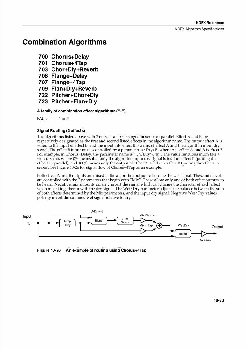
8/21/2019 MR_K2661
http://slidepdf.com/reader/full/mrk2661 155/499
KDFX Reference
KDFX Algorithm Specifications
10-73
Combination Algorithms
700 Chorus+Delay
701 Chorus+4Tap703 Chor+Dly+Reverb706 Flange+Delay707 Flange+4Tap709 Flan+Dly+Reverb722 Pitcher+Chor+Dly723 Pitcher+Flan+Dly
A family of combination effect algorithms (“+”)
PAUs: 1 or 2
Signal Routing (2 effects)
The algorithms listed above with 2 effects can be arranged in series or parallel. Effect A and B arerespectively designated as the first and second listed effects in the algorithm name. The output effect A iswired to the input of effect B, and the input into effect B is a mix of effect A and the algorithm input drysignal. The effect B input mix is controlled by a parameter A/Dry>B. where A is effect A, and B is effect B.For example, in Chorus+Delay, the parameter name is “Ch/Dry>Dly”. The value functions much like awet/dry mix where 0% means that only the algorithm input dry signal is fed into effect B (putting theeffects in parallel), and 100% means only the output of effect A is fed into effect B (putting the effects inseries). See Figure 10-26 for signal flow of Chorus+4Tap as an example.
Both effect A and B outputs are mixed at the algorithm output to become the wet signal. These mix levelsare controlled with the 2 parameters that begin with “Mix”. These allow only one or both effect outputs to
be heard. Negative mix amounts polarity invert the signal which can change the character of each effectwhen mixed together or with the dry signal. The Wet/Dry parameter adjusts the balance between the sumof both effects determined by the Mix parameters, and the input dry signal. Negative Wet/Dry valuespolarity invert the summed wet signal relative to dry.
Figure 10-26 An example of routing using Chorus+4Tap
4-Tap
Delay
InputBlend
2-Tap
Chorus
A/Dry->B
Mix 4 Tap
Mix Chorus
Blend
Wet/Dry
Out Gain
Output
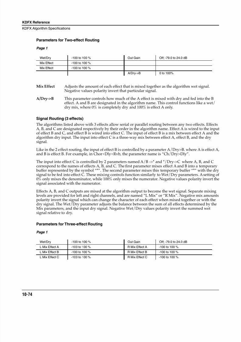
8/21/2019 MR_K2661
http://slidepdf.com/reader/full/mrk2661 156/499
10-74
KDFX Reference
KDFX Algorithm Specifications
Parameters for Two-effect Routing
Page 1
Mix Effect Adjusts the amount of each effect that is mixed together as the algorithm wet signal.Negative values polarity invert that particular signal.
A/Dry->B This parameter controls how much of the A effect is mixed with dry and fed into the Beffect. A and B are designated in the algorithm name. This control functions like a wet/dry mix, where 0% is completely dry and 100% is effect A only.
Signal Routing (3 effects)The algorithms listed above with 3 effects allow serial or parallel routing between any two effects. EffectsA, B, and C are designated respectively by their order in the algorithm name. Effect A is wired to the inputof effect B and C, and effect B is wired into effect C. The input of effect B is a mix between effect A and thealgorithm dry input. The input into effect C is a three-way mix between effect A, effect B, and the drysignal.
Like in the 2 effect routing, the input of effect B is controlled by a parameter A/Dry>B. where A is effect A,and B is effect B. For example, in Chor+Dly+Rvb, the parameter name is “Ch/Dry>Dly”.
The input into effect C is controlled by 2 parameters named A/B ->* and */Dry->C where A, B, and Ccorrespond to the names of effects A, B, and C. The first parameter mixes effect A and B into a temporary buffer represented by the symbol “*”. The second parameter mixes this temporary buffer “*” with the drysignal to be fed into effect C. These mixing controls function similarly to Wet/Dry parameters. A setting of
0% only mixes the denominator, while 100% only mixes the numerator. Negative values polarity invert thesignal associated with the numerator.
Effects A, B, and C outputs are mixed at the algorithm output to become the wet signal. Separate mixinglevels are provided for left and right channels, and are named “L Mix” or “R Mix”. Negative mix amountspolarity invert the signal which can change the character of each effect when mixed together or with thedry signal. The Wet/Dry parameter adjusts the balance between the sum of all effects determined by theMix parameters, and the input dry signal. Negative Wet/Dry values polarity invert the summed wetsignal relative to dry.
Parameters for Three-effect Routing
Page 1
Wet/Dry -100 to 100 % Out Gain Off; -79.0 to 24.0 dB
Mix Effect -100 to 100 %
Mix Effect -100 to 100 %
A/Dry->B 0 to 100%
Wet/Dry -100 to 100 % Out Gain Off; -79.0 to 24.0 dB
L Mix Effect A -100 to 100 % R Mix Effect A -100 to 100 %
L Mix Effect B -100 to 100 % R Mix Effect B -100 to 100 %
L Mix Effect C -100 to 100 % R Mix Effect C -100 to 100 %
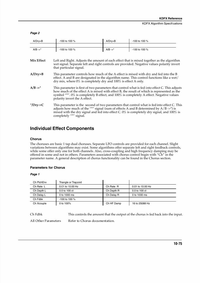
8/21/2019 MR_K2661
http://slidepdf.com/reader/full/mrk2661 157/499
KDFX Reference
KDFX Algorithm Specifications
10-75
Page 2
Mix Effect Left and Right. Adjusts the amount of each effect that is mixed together as the algorithmwet signal. Separate left and right controls are provided. Negative values polarity invertthat particular signal.
A/Dry>B This parameter controls how much of the A effect is mixed with dry and fed into the Beffect. A and B are designated in the algorithm name. This control functions like a wet/dry mix, where 0% is completely dry and 100% is effect A only.
A/B ->* This parameter is first of two parameters that control what is fed into effect C. This adjustshow much of the effect A is mixed with effect B, the result of which is represented as thesymbol “*”. 0% is completely B effect, and 100% is completely A effect. Negative values
polarity invert the A effect.*/Dry->C This parameter is the second of two parameters that control what is fed into effect C. This
adjusts how much of the “*” signal (sum of effects A and B determined by A/B ->*) ismixed with the dry signal and fed into effect C. 0% is completely dry signal, and 100% iscompletely “*” signal.
Individual Effect Components
Chorus
The choruses are basic 1 tap dual choruses. Separate LFO controls are provided for each channel. Slight
variations between algorithms may exist. Some algorithms offer separate left and right feedback controls,while some offer only one for both channels. Also, cross-coupling and high frequency damping may beoffered in some and not in others. Parameters associated with chorus control begin with “Ch” in theparameter name. A general description of chorus functionality can be found in the Chorus section.
Parameters for Chorus
Page 1
Ch Fdbk This controls the amount that the output of the chorus is fed back into the input.
All Other Parameters Refer to Chorus documentation.
A/Dry>B -100 to 100 % A/Dry>B -100 to 100 %
A/B ->* -100 to 100 % A/B ->* -100 to 100 %
Ch PtchEnv Triangle or Trapzoid
Ch Rate L 0.01 to 10.00 Hz Ch Rate R 0.01 to 10.00 Hz
Ch Depth L 0.0 to 100 ct Ch Depth R 0.0 to 100 ct
Ch Delay L 0 to 1000 ms Ch Delay R 0 to 1000 ms
Ch Fdbk -100 to 100 %
Ch Xcouple 0 to 100% Ch HF Damp 16 to 25088 Hz
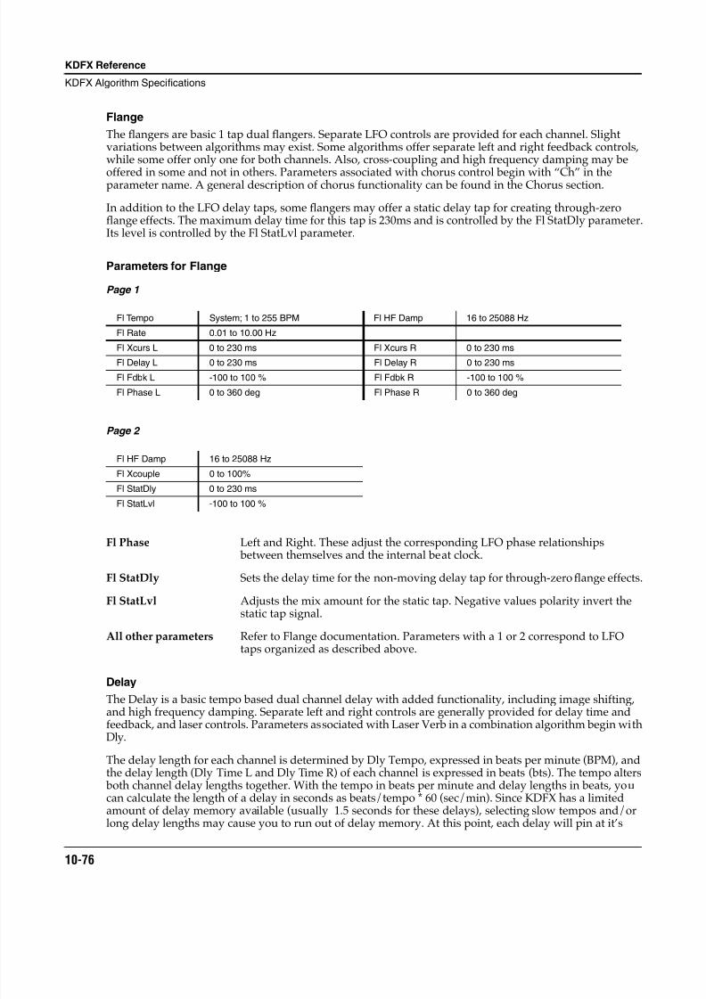
8/21/2019 MR_K2661
http://slidepdf.com/reader/full/mrk2661 158/499
10-76
KDFX Reference
KDFX Algorithm Specifications
Flange
The flangers are basic 1 tap dual flangers. Separate LFO controls are provided for each channel. Slightvariations between algorithms may exist. Some algorithms offer separate left and right feedback controls,while some offer only one for both channels. Also, cross-coupling and high frequency damping may be
offered in some and not in others. Parameters associated with chorus control begin with “Ch” in theparameter name. A general description of chorus functionality can be found in the Chorus section.
In addition to the LFO delay taps, some flangers may offer a static delay tap for creating through-zeroflange effects. The maximum delay time for this tap is 230ms and is controlled by the Fl StatDly parameter.Its level is controlled by the Fl StatLvl parameter.
Parameters for Flange
Page 1
Page 2
Fl Phase Left and Right. These adjust the corresponding LFO phase relationships between themselves and the internal beat clock.
Fl StatDly Sets the delay time for the non-moving delay tap for through-zero flange effects.
Fl StatLvl Adjusts the mix amount for the static tap. Negative values polarity invert thestatic tap signal.
All other parameters Refer to Flange documentation. Parameters with a 1 or 2 correspond to LFOtaps organized as described above.
Delay
The Delay is a basic tempo based dual channel delay with added functionality, including image shifting,and high frequency damping. Separate left and right controls are generally provided for delay time andfeedback, and laser controls. Parameters associated with Laser Verb in a combination algorithm begin withDly.
The delay length for each channel is determined by Dly Tempo, expressed in beats per minute (BPM), andthe delay length (Dly Time L and Dly Time R) of each channel is expressed in beats (bts). The tempo alters both channel delay lengths together. With the tempo in beats per minute and delay lengths in beats, youcan calculate the length of a delay in seconds as beats/tempo * 60 (sec/min). Since KDFX has a limitedamount of delay memory available (usually 1.5 seconds for these delays), selecting slow tempos and/orlong delay lengths may cause you to run out of delay memory. At this point, each delay will pin at it’s
Fl Tempo System; 1 to 255 BPM Fl HF Damp 16 to 25088 Hz
Fl Rate 0.01 to 10.00 Hz
Fl Xcurs L 0 to 230 ms Fl Xcurs R 0 to 230 msFl Delay L 0 to 230 ms Fl Delay R 0 to 230 ms
Fl Fdbk L -100 to 100 % Fl Fdbk R -100 to 100 %
Fl Phase L 0 to 360 deg Fl Phase R 0 to 360 deg
Fl HF Damp 16 to 25088 Hz
Fl Xcouple 0 to 100%
Fl StatDly 0 to 230 ms
Fl StatLvl -100 to 100 %
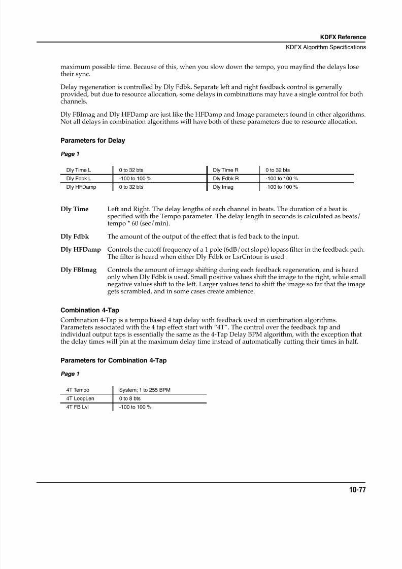
8/21/2019 MR_K2661
http://slidepdf.com/reader/full/mrk2661 159/499
KDFX Reference
KDFX Algorithm Specifications
10-77
maximum possible time. Because of this, when you slow down the tempo, you may find the delays losetheir sync.
Delay regeneration is controlled by Dly Fdbk. Separate left and right feedback control is generallyprovided, but due to resource allocation, some delays in combinations may have a single control for bothchannels.
Dly FBImag and Dly HFDamp are just like the HFDamp and Image parameters found in other algorithms.Not all delays in combination algorithms will have both of these parameters due to resource allocation.
Parameters for Delay
Page 1
Dly Time Left and Right. The delay lengths of each channel in beats. The duration of a beat isspecified with the Tempo parameter. The delay length in seconds is calculated as beats/tempo * 60 (sec/min).
Dly Fdbk The amount of the output of the effect that is fed back to the input.
Dly HFDamp Controls the cutoff frequency of a 1 pole (6dB/oct slope) lopass filter in the feedback path.The filter is heard when either Dly Fdbk or LsrCntour is used.
Dly FBImag Controls the amount of image shifting during each feedback regeneration, and is heardonly when Dly Fdbk is used. Small positive values shift the image to the right, while smallnegative values shift to the left. Larger values tend to shift the image so far that the imagegets scrambled, and in some cases create ambience.
Combination 4-Tap
Combination 4-Tap is a tempo based 4 tap delay with feedback used in combination algorithms.Parameters associated with the 4 tap effect start with “4T”. The control over the feedback tap andindividual output taps is essentially the same as the 4-Tap Delay BPM algorithm, with the exception thatthe delay times will pin at the maximum delay time instead of automatically cutting their times in half.
Parameters for Combination 4-Tap
Page 1
Dly Time L 0 to 32 bts Dly Time R 0 to 32 bts
Dly Fdbk L -100 to 100 % Dly Fdbk R -100 to 100 %
Dly HFDamp 0 to 32 bts Dly Imag -100 to 100 %
4T Tempo System; 1 to 255 BPM
4T LoopLen 0 to 8 bts4T FB Lvl -100 to 100 %
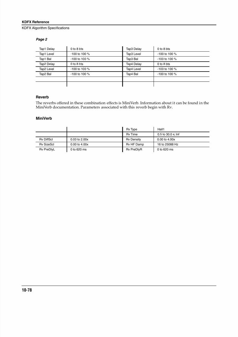
8/21/2019 MR_K2661
http://slidepdf.com/reader/full/mrk2661 160/499
10-78
KDFX Reference
KDFX Algorithm Specifications
Page 2
Reverb
The reverbs offered in these combination effects is MiniVerb. Information about it can be found in theMiniVerb documentation. Parameters associated with this reverb begin with Rv.
MiniVerb
Tap1 Delay 0 to 8 bts Tap3 Delay 0 to 8 bts
Tap1 Level -100 to 100 % Tap3 Level -100 to 100 %
Tap1 Bal -100 to 100 % Tap3 Bal -100 to 100 %Tap2 Delay 0 to 8 bts Tap4 Delay 0 to 8 bts
Tap2 Level -100 to 100 % Tap4 Level -100 to 100 %
Tap2 Bal -100 to 100 % Tap4 Bal -100 to 100 %
Rv Type Hall1
Rv Time 0.5 to 30.0 s; Inf
Rv DiffScl 0.00 to 2.00x Rv Density 0.00 to 4.00x
Rv SizeScl 0.00 to 4.00x Rv HF Damp 16 to 25088 Hz
Rv PreDlyL 0 to 620 ms Rv PreDlyR 0 to 620 ms
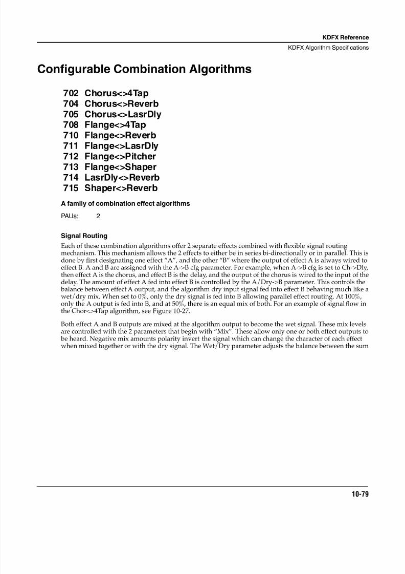
8/21/2019 MR_K2661
http://slidepdf.com/reader/full/mrk2661 161/499
KDFX Reference
KDFX Algorithm Specifications
10-79
Configurable Combination Algorithms
702 Chorus<>4Tap
704 Chorus<>Reverb705 Chorus<>LasrDly708 Flange<>4Tap710 Flange<>Reverb711 Flange<>LasrDly712 Flange<>Pitcher713 Flange<>Shaper714 LasrDly<>Reverb715 Shaper<>Reverb
A family of combination effect algorithms
PAUs: 2
Signal Routing
Each of these combination algorithms offer 2 separate effects combined with flexible signal routingmechanism. This mechanism allows the 2 effects to either be in series bi-directionally or in parallel. This isdone by first designating one effect “A”, and the other “B” where the output of effect A is always wired toeffect B. A and B are assigned with the A->B cfg parameter. For example, when A->B cfg is set to Ch->Dly,then effect A is the chorus, and effect B is the delay, and the output of the chorus is wired to the input of thedelay. The amount of effect A fed into effect B is controlled by the A/Dry->B parameter. This controls the balance between effect A output, and the algorithm dry input signal fed into effect B behaving much like awet/dry mix. When set to 0%, only the dry signal is fed into B allowing parallel effect routing. At 100%,only the A output is fed into B, and at 50%, there is an equal mix of both. For an example of signal flow inthe Chor<>4Tap algorithm, see Figure 10-27.
Both effect A and B outputs are mixed at the algorithm output to become the wet signal. These mix levelsare controlled with the 2 parameters that begin with “Mix”. These allow only one or both effect outputs to be heard. Negative mix amounts polarity invert the signal which can change the character of each effectwhen mixed together or with the dry signal. The Wet/Dry parameter adjusts the balance between the sum
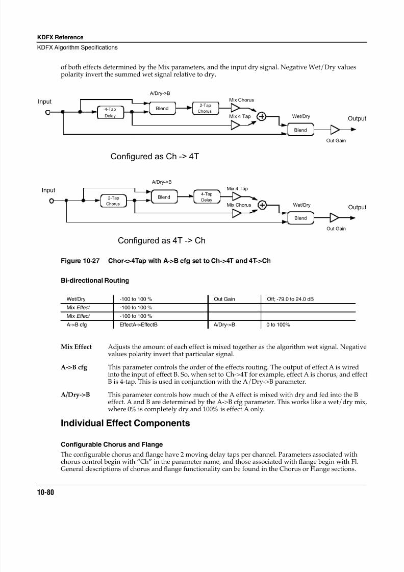
8/21/2019 MR_K2661
http://slidepdf.com/reader/full/mrk2661 162/499
10-80
KDFX Reference
KDFX Algorithm Specifications
of both effects determined by the Mix parameters, and the input dry signal. Negative Wet/Dry valuespolarity invert the summed wet signal relative to dry.
Figure 10-27 Chor<>4Tap with A->B cfg set to Ch->4T and 4T->Ch
Bi-directional Routing
Mix Effect Adjusts the amount of each effect is mixed together as the algorithm wet signal. Negativevalues polarity invert that particular signal.
A->B cfg This parameter controls the order of the effects routing. The output of effect A is wiredinto the input of effect B. So, when set to Ch->4T for example, effect A is chorus, and effectB is 4-tap. This is used in conjunction with the A/Dry->B parameter.
A/Dry->B This parameter controls how much of the A effect is mixed with dry and fed into the B
effect. A and B are determined by the A->B cfg parameter. This works like a wet/dry mix,where 0% is completely dry and 100% is effect A only.
Individual Effect Components
Configurable Chorus and Flange
The configurable chorus and flange have 2 moving delay taps per channel. Parameters associated withchorus control begin with “Ch” in the parameter name, and those associated with flange begin with Fl.General descriptions of chorus and flange functionality can be found in the Chorus or Flange sections.
Wet/Dry -100 to 100 % Out Gain Off; -79.0 to 24.0 dBMix Effect -100 to 100 %
Mix Effect -100 to 100 %
A->B cfg EffectA->EffectB A/Dry->B 0 to 100%
2-Tap
Chorus
4-Tap
DelayBlend
Blend
Input
Output
Mix 4 Tap
Mix Chorus
Out Gain
A/Dry->B
Wet/Dry
Configured as 4T -> Ch
Configured as Ch -> 4T
4-Tap
Delay
InputBlend
2-Tap
Chorus
A/Dry->B
Mix 4 Tap
Mix Chorus
Blend
Wet/Dry
Out Gain
Output
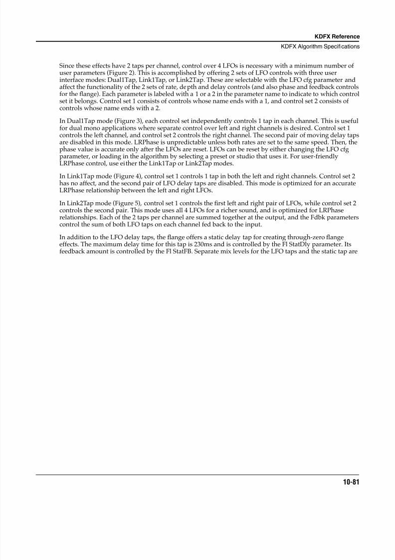
8/21/2019 MR_K2661
http://slidepdf.com/reader/full/mrk2661 163/499
KDFX Reference
KDFX Algorithm Specifications
10-81
Since these effects have 2 taps per channel, control over 4 LFOs is necessary with a minimum number ofuser parameters (Figure 2). This is accomplished by offering 2 sets of LFO controls with three userinterface modes: Dual1Tap, Link1Tap, or Link2Tap. These are selectable with the LFO cfg parameter andaffect the functionality of the 2 sets of rate, depth and delay controls (and also phase and feedback controlsfor the flange). Each parameter is labeled with a 1 or a 2 in the parameter name to indicate to which controlset it belongs. Control set 1 consists of controls whose name ends with a 1, and control set 2 consists ofcontrols whose name ends with a 2.
In Dual1Tap mode (Figure 3), each control set independently controls 1 tap in each channel. This is usefulfor dual mono applications where separate control over left and right channels is desired. Control set 1controls the left channel, and control set 2 controls the right channel. The second pair of moving delay tapsare disabled in this mode. LRPhase is unpredictable unless both rates are set to the same speed. Then, thephase value is accurate only after the LFOs are reset. LFOs can be reset by either changing the LFO cfgparameter, or loading in the algorithm by selecting a preset or studio that uses it. For user-friendlyLRPhase control, use either the Link1Tap or Link2Tap modes.
In Link1Tap mode (Figure 4), control set 1 controls 1 tap in both the left and right channels. Control set 2has no affect, and the second pair of LFO delay taps are disabled. This mode is optimized for an accurateLRPhase relationship between the left and right LFOs.
In Link2Tap mode (Figure 5), control set 1 controls the first left and right pair of LFOs, while control set 2controls the second pair. This mode uses all 4 LFOs for a richer sound, and is optimized for LRPhaserelationships. Each of the 2 taps per channel are summed together at the output, and the Fdbk parameterscontrol the sum of both LFO taps on each channel fed back to the input.
In addition to the LFO delay taps, the flange offers a static delay tap for creating through-zero flangeeffects. The maximum delay time for this tap is 230ms and is controlled by the Fl StatDly parameter. Itsfeedback amount is controlled by the Fl StatFB. Separate mix levels for the LFO taps and the static tap are
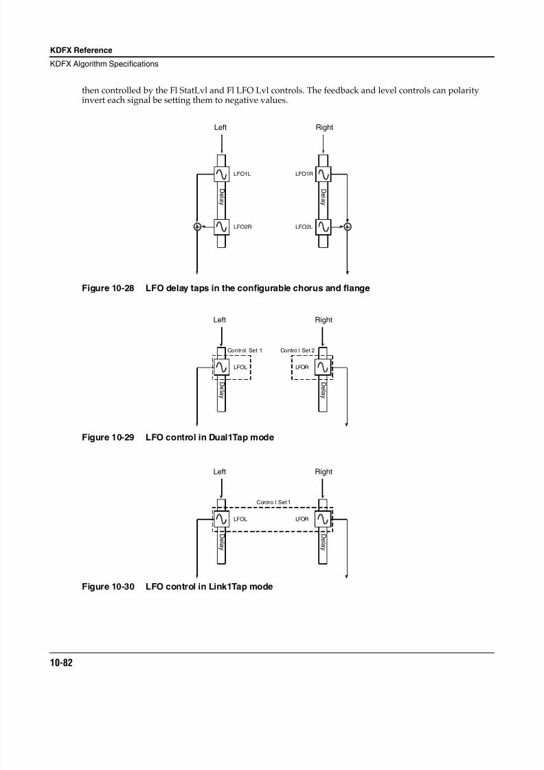
8/21/2019 MR_K2661
http://slidepdf.com/reader/full/mrk2661 164/499
10-82
KDFX Reference
KDFX Algorithm Specifications
then controlled by the Fl StatLvl and Fl LFO Lvl controls. The feedback and level controls can polarityinvert each signal be setting them to negative values.
Figure 10-28 LFO delay taps in the configurable chorus and flange
Figure 10-29 LFO control in Dual1Tap mode
Figure 10-30 LFO control in Link1Tap mode
LFO1R
LFO2L
Right
D el a y
LFO2R
Left
LFO1L
D el a y
LFOR
Right
D el a y
Left
LFOL
D el a y
Control Set 1 Contro l Set 2
LFOR
Right
D
el a y
Left
LFOL
D
el a y
Contro l Set 1
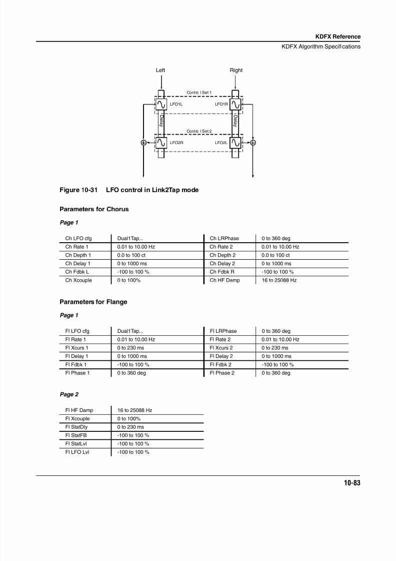
8/21/2019 MR_K2661
http://slidepdf.com/reader/full/mrk2661 165/499
KDFX Reference
KDFX Algorithm Specifications
10-83
Figure 10-31 LFO control in Link2Tap mode
Parameters for Chorus
Page 1
Parameters for Flange
Page 1
Page 2
Ch LFO cfg Dual1Tap... Ch LRPhase 0 to 360 deg
Ch Rate 1 0.01 to 10.00 Hz Ch Rate 2 0.01 to 10.00 Hz
Ch Depth 1 0.0 to 100 ct Ch Depth 2 0.0 to 100 ct
Ch Delay 1 0 to 1000 ms Ch Delay 2 0 to 1000 ms
Ch Fdbk L -100 to 100 % Ch Fdbk R -100 to 100 %
Ch Xcouple 0 to 100% Ch HF Damp 16 to 25088 Hz
Fl LFO cfg Dual1Tap... Fl LRPhase 0 to 360 deg
Fl Rate 1 0.01 to 10.00 Hz Fl Rate 2 0.01 to 10.00 Hz
Fl Xcurs 1 0 to 230 ms Fl Xcurs 2 0 to 230 ms
Fl Delay 1 0 to 1000 ms Fl Delay 2 0 to 1000 ms
Fl Fdbk 1 -100 to 100 % Fl Fdbk 2 -100 to 100 %
Fl Phase 1 0 to 360 deg Fl Phase 2 0 to 360 deg
Fl HF Damp 16 to 25088 Hz
Fl Xcouple 0 to 100%
Fl StatDly 0 to 230 ms
Fl StatFB -100 to 100 %
Fl StatLvl -100 to 100 %
Fl LFO Lvl -100 to 100 %
LFO1R
LFO2L
Right
D el a y
LFO2R
Left
LFO1L
D el a y
Contro l Set 1
Contro l Set 2
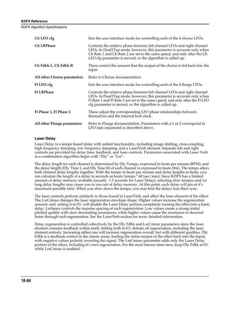
8/21/2019 MR_K2661
http://slidepdf.com/reader/full/mrk2661 166/499
10-84
KDFX Reference
KDFX Algorithm Specifications
Ch LFO cfg Sets the user interface mode for controlling each of the 4 chorus LFOs.
Ch LRPhase Controls the relative phase between left channel LFOs and right channelLFOs. In Dual1Tap mode, however, this parameter is accurate only whenCh Rate 1 and Ch Rate 2 are set to the same speed, and only after the ChLFO cfg parameter is moved, or the algorithm is called up.
Ch Fdbk L, Ch Fdbk R These control the amount that the output of the chorus is fed back into theinput.
All other Chorus parameters Refer to Chorus documentation.
Fl LFO cfg Sets the user interface mode for controlling each of the 4 flange LFOs.
Fl LRPhase Controls the relative phase between left channel LFOs and right channelLFOs. In Dual1Tap mode, however, this parameter is accurate only whenFl Rate 1 and Fl Rate 2 are set to the same speed, and only after the Fl LFOcfg parameter is moved, or the algorithm is called up.
Fl Phase 1, Fl Phase 2 These adjust the corresponding LFO phase relationships betweenthemselves and the internal beat clock.
All other Flange parameters Refer to Flange documentation. Parameters with a 1 or 2 correspond toLFO taps organized as described above.
Laser Delay
Laser Delay is a tempo based delay with added functionality, including image shifting, cross-coupling,high frequency damping, low frequency damping, and a LaserVerb element. Separate left and rightcontrols are provided for delay time, feedback, and laser controls. Parameters associated with Laser Verbin a combination algorithm begin with “Dly” or “Lsr”.
The delay length for each channel is determined by Dly Tempo, expressed in beats per minute (BPM), andthe delay length (Dly Time L and Dly Time R) of each channel is expressed in beats (bts). The tempo alters
both channel delay lengths together. With the tempo in beats per minute and delay lengths in beats, youcan calculate the length of a delay in seconds as beats/tempo * 60 (sec/min). Since KDFX has a limitedamount of delay memory available (usually 1.5 seconds for Laser Delay), selecting slow tempos and/orlong delay lengths may cause you to run out of delay memory. At this point, each delay will pin at it’smaximum possible time. When you slow down the tempo, you may find the delays lose their sync.
The laser controls perform similarly to those found in LaserVerb, and affect the laser element of the effect.The LsrCntour changes the laser regeneration envelope shape. Higher values increase the regenerationamount, and setting it to 0% will disable the Laser Delay portion completely turning the effect into a basicdelay. LsrSpace controls the impulse spacing of each regeneration. Low values create a strong initialpitched quality with slow descending resonances, while higher values cause the resonance to descendfaster through each regeneration. See the LaserVerb section for more detailed information.
Delay regeneration is controlled collectively by the Dly Fdbk and LsrCntour parameters since the laser
element contains feedback within itself. Setting both to 0% defeats all regeneration, including the laserelement entirely. Increasing either one will increase regeneration overall, but with different qualities. DlyFdbk is a feedback control in the classic sense, feeding the entire output of the effect back into the input,with negative values polarity inverting the signal. The LsrCntour parameter adds only the Laser Delayportion of the effect, including it’s own regeneration. For the most intense laser-ness, keep Dly Fdbk at 0%while LsrCntour is enabled.
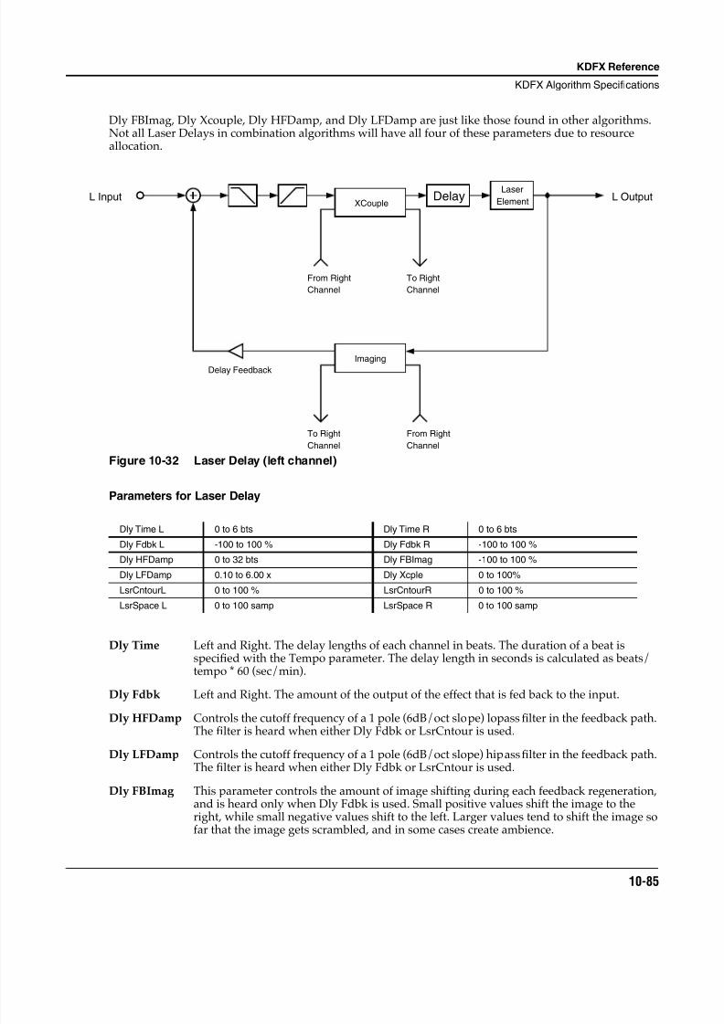
8/21/2019 MR_K2661
http://slidepdf.com/reader/full/mrk2661 167/499
KDFX Reference
KDFX Algorithm Specifications
10-85
Dly FBImag, Dly Xcouple, Dly HFDamp, and Dly LFDamp are just like those found in other algorithms.Not all Laser Delays in combination algorithms will have all four of these parameters due to resourceallocation.
Figure 10-32 Laser Delay (left channel)
Parameters for Laser Delay
Dly Time Left and Right. The delay lengths of each channel in beats. The duration of a beat isspecified with the Tempo parameter. The delay length in seconds is calculated as beats/tempo * 60 (sec/min).
Dly Fdbk Left and Right. The amount of the output of the effect that is fed back to the input.
Dly HFDamp Controls the cutoff frequency of a 1 pole (6dB/oct slope) lopass filter in the feedback path.The filter is heard when either Dly Fdbk or LsrCntour is used.
Dly LFDamp Controls the cutoff frequency of a 1 pole (6dB/oct slope) hipass filter in the feedback path.The filter is heard when either Dly Fdbk or LsrCntour is used.
Dly FBImag This parameter controls the amount of image shifting during each feedback regeneration,and is heard only when Dly Fdbk is used. Small positive values shift the image to theright, while small negative values shift to the left. Larger values tend to shift the image sofar that the image gets scrambled, and in some cases create ambience.
Dly Time L 0 to 6 bts Dly Time R 0 to 6 bts
Dly Fdbk L -100 to 100 % Dly Fdbk R -100 to 100 %
Dly HFDamp 0 to 32 bts Dly FBImag -100 to 100 %
Dly LFDamp 0.10 to 6.00 x Dly Xcple 0 to 100%
LsrCntourL 0 to 100 % LsrCntourR 0 to 100 %
LsrSpace L 0 to 100 samp LsrSpace R 0 to 100 samp
L InputXCouple
Imaging
L Output
From Right
Channel
To Right
Channel
Channel
From Right
Channel
To Right
Delay Feedback
DelayLaser
Element
8/21/2019 MR_K2661
http://slidepdf.com/reader/full/mrk2661 168/499
10-86
KDFX Reference
KDFX Algorithm Specifications
Dly Xcple This parameter controls the amount of signal that is swapped between the left and rightchannels through each feedback generation when Dly Fdbk is used. A setting of 0% has noaffect. 50% causes equal amounts of signal to be present in both channels causing theimage to collapse into a center point source. A setting of 100% causes the left and rightchannels to swap each regeneration, which is also referred to as “ping-ponging”. Theregeneration affects of cross-coupling are not heard when LsrCntour is used by itself.
LsrCntour Left and Right. Controls the overall envelope shape of the laser regeneration. When set toa high value, sounds passing through will start at a high level and slowly decay. As thecontrol value is reduced, it takes some time for the effect to build up before decaying.When the Contour is set to zero, the laser portion is turned off turning regeneration intostraight feedback.
LsrSpace Left and Right. Determines the starting pitch of the descending resonance and how fast itdescends. See the section on Laser Delay for more detailed information.
Combination 4-Tap
Combination 4-Tap is a tempo based 4 tap delay with feedback used in combination algorithms.
Parameters associated with the 4 tap effect start with “4T”. The control over the feedback tap andindividual output taps is essentially the same as the 4-Tap Delay BPM algorithm, with the exception thatthe delay times will pin at the maximum delay time instead of automatically cutting their times in half.Additionally, the feedback path may also offer cross-coupling, an imager, a hipass filter, and/or a lopassfilter.
Parameters for Combination 4-Tap
Page 1
Page 2
4T FB Imag This parameter controls the amount of image shifting during each feedbackregeneration. Small positive values shift the image to the right, while smallnegative values shift to the left. Larger values tend to shift the image so far thatthe image gets scrambled, and in some cases create ambience.
4T FB Xcpl This parameter controls the amount of signal that is swapped between the leftand right channels through each feedback regeneration. A setting of 0% has noaffect. 50% causes equal amounts of signal to be present in both channels
4T LoopLen 0 to 32 bts
4T FB Lvl -100 to 100 %
4T FB Imag -100 to 100 %
4T FB XCpl 0 to 100 %
4T HF Damp 16 to 25088 Hz
4T LF Damp 16 to 25088 Hz
Tap1 Delay 0 to 32 bts Tap3 Delay 0 to 32 bts
Tap1 Level -100 to 100 % Tap3 Level -100 to 100 %
Tap1 Bal -100 to 100 % Tap3 Bal -100 to 100 %
Tap2 Delay 0 to 32 bts Tap4 Delay 0 to 32 bts
Tap2 Level -100 to 100 % Tap4 Level -100 to 100 %
Tap2 Bal -100 to 100 % Tap4 Bal -100 to 100 %
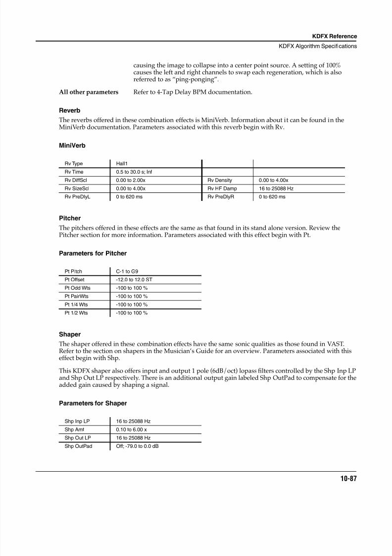
8/21/2019 MR_K2661
http://slidepdf.com/reader/full/mrk2661 169/499
KDFX Reference
KDFX Algorithm Specifications
10-87
causing the image to collapse into a center point source. A setting of 100%causes the left and right channels to swap each regeneration, which is alsoreferred to as “ping-ponging”.
All other parameters Refer to 4-Tap Delay BPM documentation.
Reverb
The reverbs offered in these combination effects is MiniVerb. Information about it can be found in theMiniVerb documentation. Parameters associated with this reverb begin with Rv.
MiniVerb
Pitcher
The pitchers offered in these effects are the same as that found in its stand alone version. Review thePitcher section for more information. Parameters associated with this effect begin with Pt.
Parameters for Pitcher
Shaper
The shaper offered in these combination effects have the same sonic qualities as those found in VAST.Refer to the section on shapers in the Musician’s Guide for an overview. Parameters associated with thiseffect begin with Shp.
This KDFX shaper also offers input and output 1 pole (6dB/oct) lopass filters controlled by the Shp Inp LPand Shp Out LP respectively. There is an additional output gain labeled Shp OutPad to compensate for theadded gain caused by shaping a signal.
Parameters for Shaper
Rv Type Hall1
Rv Time 0.5 to 30.0 s; Inf
Rv DiffScl 0.00 to 2.00x Rv Density 0.00 to 4.00x
Rv SizeScl 0.00 to 4.00x Rv HF Damp 16 to 25088 Hz
Rv PreDlyL 0 to 620 ms Rv PreDlyR 0 to 620 ms
Pt Pitch C-1 to G9
Pt Offset -12.0 to 12.0 ST
Pt Odd Wts -100 to 100 %
Pt PairWts -100 to 100 %
Pt 1/4 Wts -100 to 100 %
Pt 1/2 Wts -100 to 100 %
Shp Inp LP 16 to 25088 Hz
Shp Amt 0.10 to 6.00 x
Shp Out LP 16 to 25088 Hz
Shp OutPad Off; -79.0 to 0.0 dB

8/21/2019 MR_K2661
http://slidepdf.com/reader/full/mrk2661 170/499
10-88
KDFX Reference
KDFX Algorithm Specifications
Shp Inp LP Adjusts the cutoff frequency of the 1 pole (6dB/oct) lopass filter at the input of the shaper.
Shp Out LP Adjusts the cutoff frequency of the 1 pole (6dB/oct) lopass filter at the output of theshaper.
Shp Amount Adjusts the shaper intensity. This is exactly like the one in VAST.
Shp OutPad Adjusts the output gain at the output of the shaper to compensate for added gain caused by the shaper.
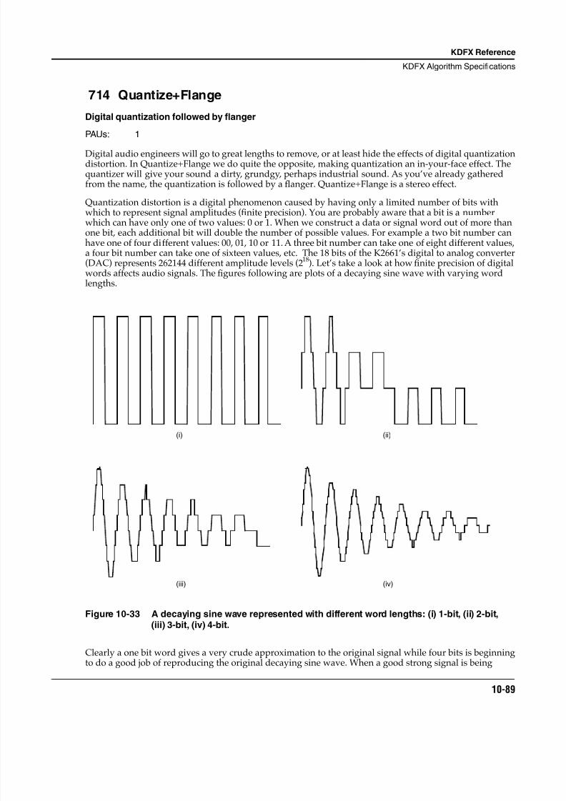
8/21/2019 MR_K2661
http://slidepdf.com/reader/full/mrk2661 171/499
KDFX Reference
KDFX Algorithm Specifications
10-89
714 Quantize+Flange
Digital quantization followed by flanger
PAUs: 1
Digital audio engineers will go to great lengths to remove, or at least hide the effects of digital quantizationdistortion. In Quantize+Flange we do quite the opposite, making quantization an in-your-face effect. Thequantizer will give your sound a dirty, grundgy, perhaps industrial sound. As you’ve already gatheredfrom the name, the quantization is followed by a flanger. Quantize+Flange is a stereo effect.
Quantization distortion is a digital phenomenon caused by having only a limited number of bits withwhich to represent signal amplitudes (finite precision). You are probably aware that a bit is a numberwhich can have only one of two values: 0 or 1. When we construct a data or signal word out of more thanone bit, each additional bit will double the number of possible values. For example a two bit number canhave one of four different values: 00, 01, 10 or 11. A three bit number can take one of eight different values,a four bit number can take one of sixteen values, etc. The 18 bits of the K2661’s digital to analog converter(DAC) represents 262144 different amplitude levels (218). Let’s take a look at how finite precision of digitalwords affects audio signals. The figures following are plots of a decaying sine wave with varying wordlengths.
Figure 10-33 A decaying sine wave represented with different word lengths: (i) 1-bit, (ii) 2-bit,(iii) 3-bit, (iv) 4-bit.
Clearly a one bit word gives a very crude approximation to the original signal while four bits is beginningto do a good job of reproducing the original decaying sine wave. When a good strong signal is being
(i) (ii)
(iii) (iv)
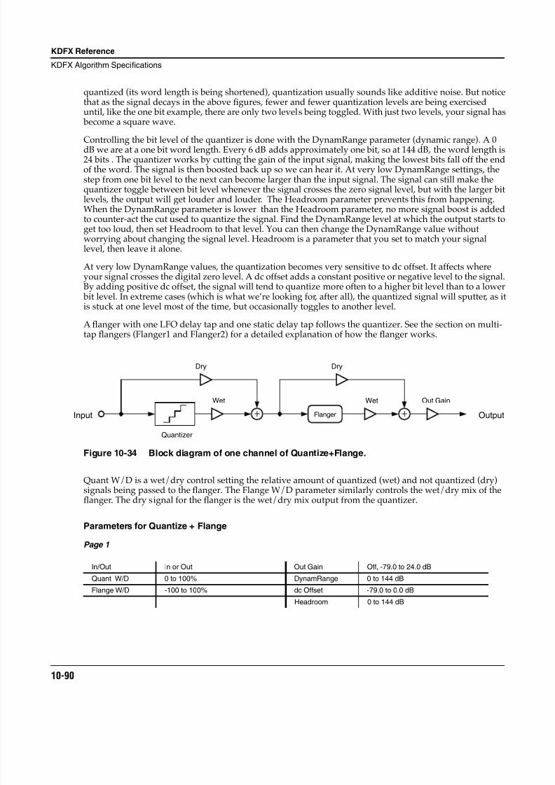
8/21/2019 MR_K2661
http://slidepdf.com/reader/full/mrk2661 172/499
10-90
KDFX Reference
KDFX Algorithm Specifications
quantized (its word length is being shortened), quantization usually sounds like additive noise. But noticethat as the signal decays in the above figures, fewer and fewer quantization levels are being exerciseduntil, like the one bit example, there are only two levels being toggled. With just two levels, your signal has become a square wave.
Controlling the bit level of the quantizer is done with the DynamRange parameter (dynamic range). A 0dB we are at a one bit word length. Every 6 dB adds approximately one bit, so at 144 dB, the word length is24 bits . The quantizer works by cutting the gain of the input signal, making the lowest bits fall off the endof the word. The signal is then boosted back up so we can hear it. At very low DynamRange settings, thestep from one bit level to the next can become larger than the input signal. The signal can still make thequantizer toggle between bit level whenever the signal crosses the zero signal level, but with the larger bitlevels, the output will get louder and louder. The Headroom parameter prevents this from happening.When the DynamRange parameter is lower than the Headroom parameter, no more signal boost is addedto counter-act the cut used to quantize the signal. Find the DynamRange level at which the output starts toget too loud, then set Headroom to that level. You can then change the DynamRange value withoutworrying about changing the signal level. Headroom is a parameter that you set to match your signallevel, then leave it alone.
At very low DynamRange values, the quantization becomes very sensitive to dc offset. It affects where
your signal crosses the digital zero level. A dc offset adds a constant positive or negative level to the signal.By adding positive dc offset, the signal will tend to quantize more often to a higher bit level than to a lower bit level. In extreme cases (which is what we’re looking for, after all), the quantized signal will sputter, as itis stuck at one level most of the time, but occasionally toggles to another level.
A flanger with one LFO delay tap and one static delay tap follows the quantizer. See the section on multi-tap flangers (Flanger1 and Flanger2) for a detailed explanation of how the flanger works.
Figure 10-34 Block diagram of one channel of Quantize+Flange.
Quant W/D is a wet/dry control setting the relative amount of quantized (wet) and not quantized (dry)signals being passed to the flanger. The Flange W/D parameter similarly controls the wet/dry mix of theflanger. The dry signal for the flanger is the wet/dry mix output from the quantizer.
Parameters for Quantize + Flange
Page 1
In/Out In or Out Out Gain Off, -79.0 to 24.0 dB
Quant W/D 0 to 100% DynamRange 0 to 144 dB
Flange W/D -100 to 100% dc Offset -79.0 to 0.0 dB
Headroom 0 to 144 dB
Input
Wet
Dry
Out Gain
Flanger
Dry
Wet
Output
Quantizer
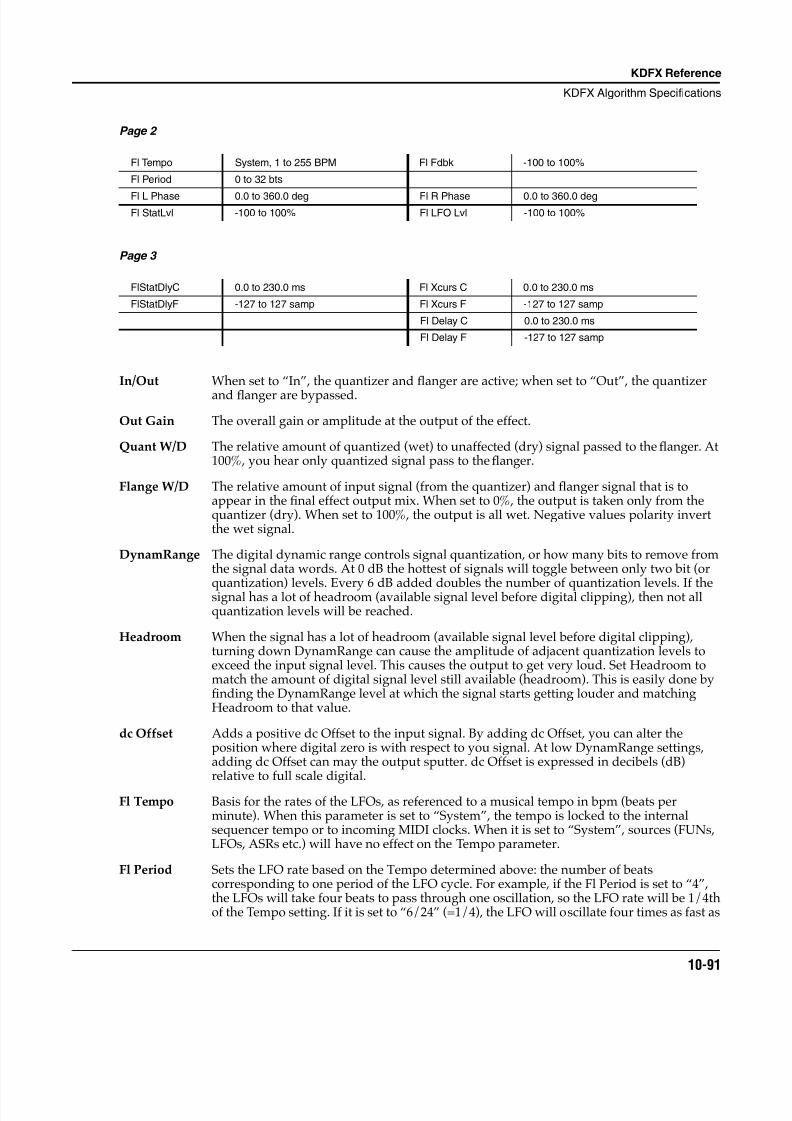
8/21/2019 MR_K2661
http://slidepdf.com/reader/full/mrk2661 173/499
KDFX Reference
KDFX Algorithm Specifications
10-91
Page 2
Page 3
In/Out When set to “In”, the quantizer and flanger are active; when set to “Out”, the quantizer
and flanger are bypassed.
Out Gain The overall gain or amplitude at the output of the effect.
Quant W/D The relative amount of quantized (wet) to unaffected (dry) signal passed to the flanger. At100%, you hear only quantized signal pass to the flanger.
Flange W/D The relative amount of input signal (from the quantizer) and flanger signal that is toappear in the final effect output mix. When set to 0%, the output is taken only from thequantizer (dry). When set to 100%, the output is all wet. Negative values polarity invertthe wet signal.
DynamRange The digital dynamic range controls signal quantization, or how many bits to remove fromthe signal data words. At 0 dB the hottest of signals will toggle between only two bit (or
quantization) levels. Every 6 dB added doubles the number of quantization levels. If thesignal has a lot of headroom (available signal level before digital clipping), then not allquantization levels will be reached.
Headroom When the signal has a lot of headroom (available signal level before digital clipping),turning down DynamRange can cause the amplitude of adjacent quantization levels toexceed the input signal level. This causes the output to get very loud. Set Headroom tomatch the amount of digital signal level still available (headroom). This is easily done byfinding the DynamRange level at which the signal starts getting louder and matchingHeadroom to that value.
dc Offset Adds a positive dc Offset to the input signal. By adding dc Offset, you can alter theposition where digital zero is with respect to you signal. At low DynamRange settings,adding dc Offset can may the output sputter. dc Offset is expressed in decibels (dB)relative to full scale digital.
Fl Tempo Basis for the rates of the LFOs, as referenced to a musical tempo in bpm (beats perminute). When this parameter is set to “System”, the tempo is locked to the internalsequencer tempo or to incoming MIDI clocks. When it is set to “System”, sources (FUNs,LFOs, ASRs etc.) will have no effect on the Tempo parameter.
Fl Period Sets the LFO rate based on the Tempo determined above: the number of beatscorresponding to one period of the LFO cycle. For example, if the Fl Period is set to “4”,the LFOs will take four beats to pass through one oscillation, so the LFO rate will be 1/4thof the Tempo setting. If it is set to “6/24” (=1/4), the LFO will oscillate four times as fast as
Fl Tempo System, 1 to 255 BPM Fl Fdbk -100 to 100%
Fl Period 0 to 32 bts
Fl L Phase 0.0 to 360.0 deg Fl R Phase 0.0 to 360.0 degFl StatLvl -100 to 100% Fl LFO Lvl -100 to 100%
FlStatDlyC 0.0 to 230.0 ms Fl Xcurs C 0.0 to 230.0 ms
FlStatDlyF -127 to 127 samp Fl Xcurs F -127 to 127 samp
Fl Delay C 0.0 to 230.0 ms
Fl Delay F -127 to 127 samp
8/21/2019 MR_K2661
http://slidepdf.com/reader/full/mrk2661 174/499
10-92
KDFX Reference
KDFX Algorithm Specifications
the Tempo. At “0”, the LFOs stop oscillating and their phase is undetermined (whereverthey stopped).
Fl Fdbk The level of the flanger feedback signal into the flanger delay line. The feedback signal istaken from the LFO delay tap. Negative values polarity invert the feedback signal.
Fl L/R Phase The phase angles of the left and right LFOs relative to each other and to the system tempoclock, if turned on (see Fl Tempo). In all other respects the right and left channels aresymmetric. For example, if one LFO is set to 0° and another is set to 180°, then when oneLFO delay tap is at its shortest, the other will be at its longest. If the system tempo clock ison, the LFOs are synchronized to the clock with absolute phase. A phase of 0° will put anLFO tap at the center of its range and its lengthening. Using different phase angles for leftand right, the stereo sound field is broken up and a stereo image becomes dif ficult tospatially locate. The effect is usually described as “phasey”. It tends to impart a greatersense of motion.
Fl StatLvl The level of the flanger static delay tap. Negative values polarity invert the signal. Settingthe tap level to 0% turns off the delay tap.
Fl LFO Lvl The level of the flanger LFO modulated delay tap. Negative values polarity invert thesignal. Setting the tap level to 0% turns off the delay tap.
FlStatDlyC The nominal length of the flanger static delay tap from the delay input. The namesuggests the tap is stationary, but it can be connected to a control source such as a dataslider, a ribbon, or a V.A.S.T. function to smoothly vary the delay length. The range for alldelays and excursions is 0 to 230 ms, but for flanging the range 0 to 5 ms is most effective.
FlStatDlyF A fine adjustment to the flanger static delay tap length. The resolution is one sample.
Fl Xcurs C The flanger LFO excursion controls set how far the LFO modulated delay taps can movefrom the center of their ranges. The total range of the LFO sweep is twice the excursion. Ifthe excursion is set to 0, the LFO does not move and the tap behaves like a simple delayline set to the minimum delay. The range for all delays and excursions is 0 to 230 ms, butfor flanging the range 0 to 5 ms is most effective. This parameter is a coarse adjustment forthe excursion.
Fl Xcurs F A fine adjustment for the flanger LFO excursions. The resolution is one sample.
Fl Delay C The minimum delay for the flanger LFO modulated delay taps. The maximum delay will be the minimum plus twice the excursion. The range for all delays and excursions is 0 to230 ms, but for flanging the range 0 to 5 ms is most effective. This parameter is a coarseadjustment for the delay.
Fl Delay F A fine adjustment to the minimum flanger delay tap lengths. The resolution is one sample.
8/21/2019 MR_K2661
http://slidepdf.com/reader/full/mrk2661 175/499
KDFX Reference
KDFX Algorithm Specifications
10-93
715 Dual MovDelay716 Quad MovDelay
Generic dual mono moving delay lines
PAUs: 1 for Dual2 for Quad
Each of these algorithms offers generic moving delay lines in a dual mono configuration. Each separatemoving delay can be used as a flanger, chorus, or static delay line selectable by the LFO Mode parameter.Both flavors of chorus pitch envelopes are offered: ChorTri for triangle, and ChorTrap for trapezoidal pitchshifting. Refer to the Chorus section for more information on these envelope shapes.
The value functions much like a wet/dry mix where 0% means that only the algorithm input dry signal isfed into effect B (putting the effects in parallel), and 100% means only the output of effect A is fed intoeffect B (putting the effects in series). See Figure 1 for signal flow of Chorus+4Tap as an example.
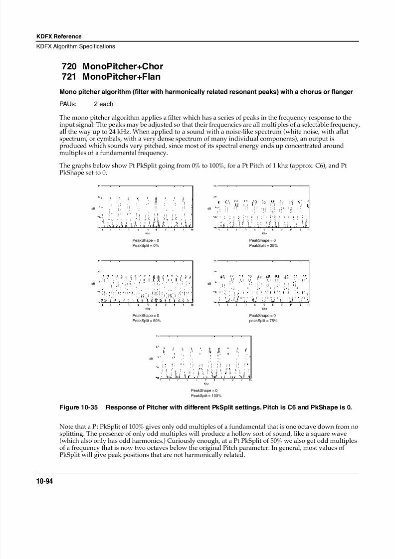
8/21/2019 MR_K2661
http://slidepdf.com/reader/full/mrk2661 176/499
10-94
KDFX Reference
KDFX Algorithm Specifications
720 MonoPitcher+Chor721 MonoPitcher+Flan
Mono pitcher algorithm (filter with harmonically related resonant peaks) with a chorus or flanger
PAUs: 2 each
The mono pitcher algorithm applies a filter which has a series of peaks in the frequency response to theinput signal. The peaks may be adjusted so that their frequencies are all multiples of a selectable frequency,all the way up to 24 kHz. When applied to a sound with a noise-like spectrum (white noise, with a flatspectrum, or cymbals, with a very dense spectrum of many individual components), an output isproduced which sounds very pitched, since most of its spectral energy ends up concentrated aroundmultiples of a fundamental frequency.
The graphs below show Pt PkSplit going from 0% to 100%, for a Pt Pitch of 1 khz (approx. C6), and PtPkShape set to 0.
Figure 10-35 Response of Pitcher with different PkSplit settings. Pitch is C6 and PkShape is 0.
Note that a Pt PkSplit of 100% gives only odd multiples of a fundamental that is one octave down from nosplitting. The presence of only odd multiples will produce a hollow sort of sound, like a square wave(which also only has odd harmonics.) Curiously enough, at a Pt PkSplit of 50% we also get odd multiplesof a frequency that is now two octaves below the original Pitch parameter. In general, most values ofPkSplit will give peak positions that are not harmonically related.
PeakShape = 0
PeakSplit = 0%
Khz
dB
PeakShape = 0
PeakSplit = 25%
Khz
dB
PeakShape = 0
PeakSplit = 50%
Khz
dB
PeakShape = 0
peakSplit = 75%
Khz
dB
PeakShape = 0PeakSplit = 100%
Khz
dB
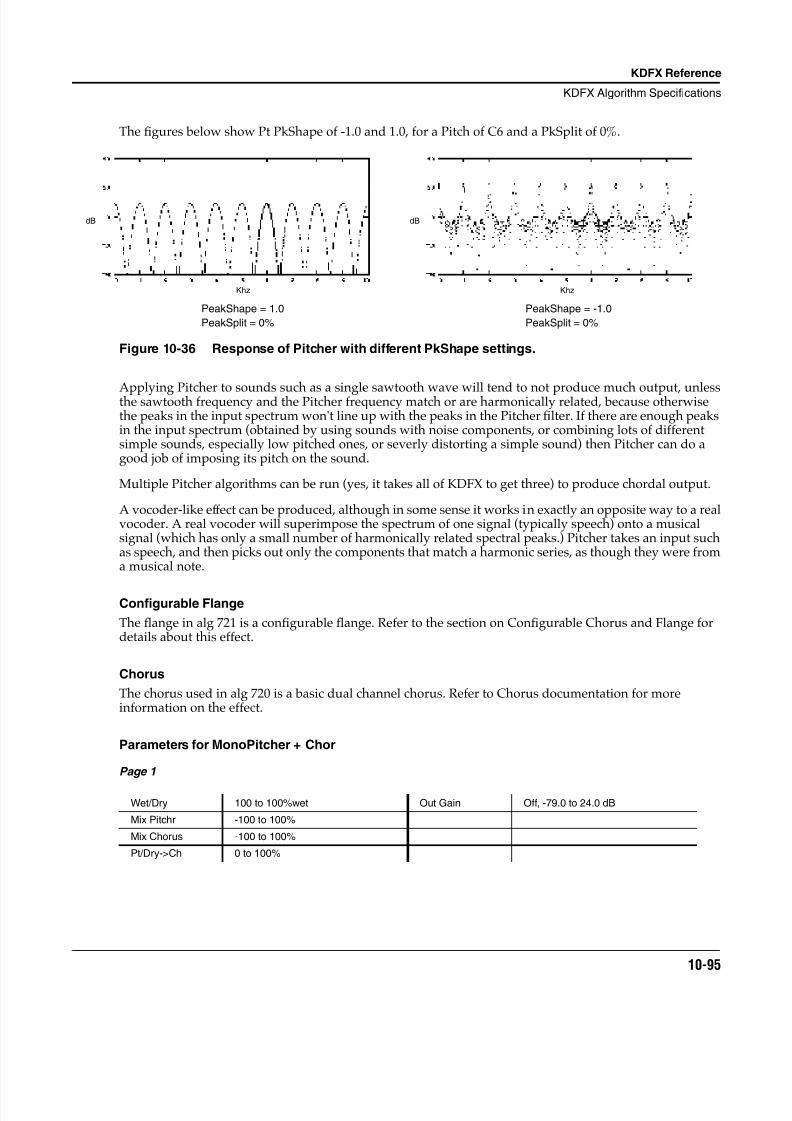
8/21/2019 MR_K2661
http://slidepdf.com/reader/full/mrk2661 177/499
KDFX Reference
KDFX Algorithm Specifications
10-95
The figures below show Pt PkShape of -1.0 and 1.0, for a Pitch of C6 and a PkSplit of 0%.
Figure 10-36 Response of Pitcher with different PkShape settings.
Applying Pitcher to sounds such as a single sawtooth wave will tend to not produce much output, unlessthe sawtooth frequency and the Pitcher frequency match or are harmonically related, because otherwisethe peaks in the input spectrum won't line up with the peaks in the Pitcher filter. If there are enough peaksin the input spectrum (obtained by using sounds with noise components, or combining lots of differentsimple sounds, especially low pitched ones, or severly distorting a simple sound) then Pitcher can do agood job of imposing its pitch on the sound.
Multiple Pitcher algorithms can be run (yes, it takes all of KDFX to get three) to produce chordal output.
A vocoder-like effect can be produced, although in some sense it works in exactly an opposite way to a realvocoder. A real vocoder will superimpose the spectrum of one signal (typically speech) onto a musicalsignal (which has only a small number of harmonically related spectral peaks.) Pitcher takes an input suchas speech, and then picks out only the components that match a harmonic series, as though they were froma musical note.
Configurable Flange
The flange in alg 721 is a configurable flange. Refer to the section on Configurable Chorus and Flange fordetails about this effect.
Chorus
The chorus used in alg 720 is a basic dual channel chorus. Refer to Chorus documentation for moreinformation on the effect.
Parameters for MonoPitcher + Chor
Page 1
Wet/Dry 100 to 100%wet Out Gain Off, -79.0 to 24.0 dB
Mix Pitchr -100 to 100%
Mix Chorus -100 to 100%
Pt/Dry->Ch 0 to 100%
PeakShape = -1.0
PeakSplit = 0%
Khz
dB
PeakShape = 1.0
PeakSplit = 0%
Khz
dB
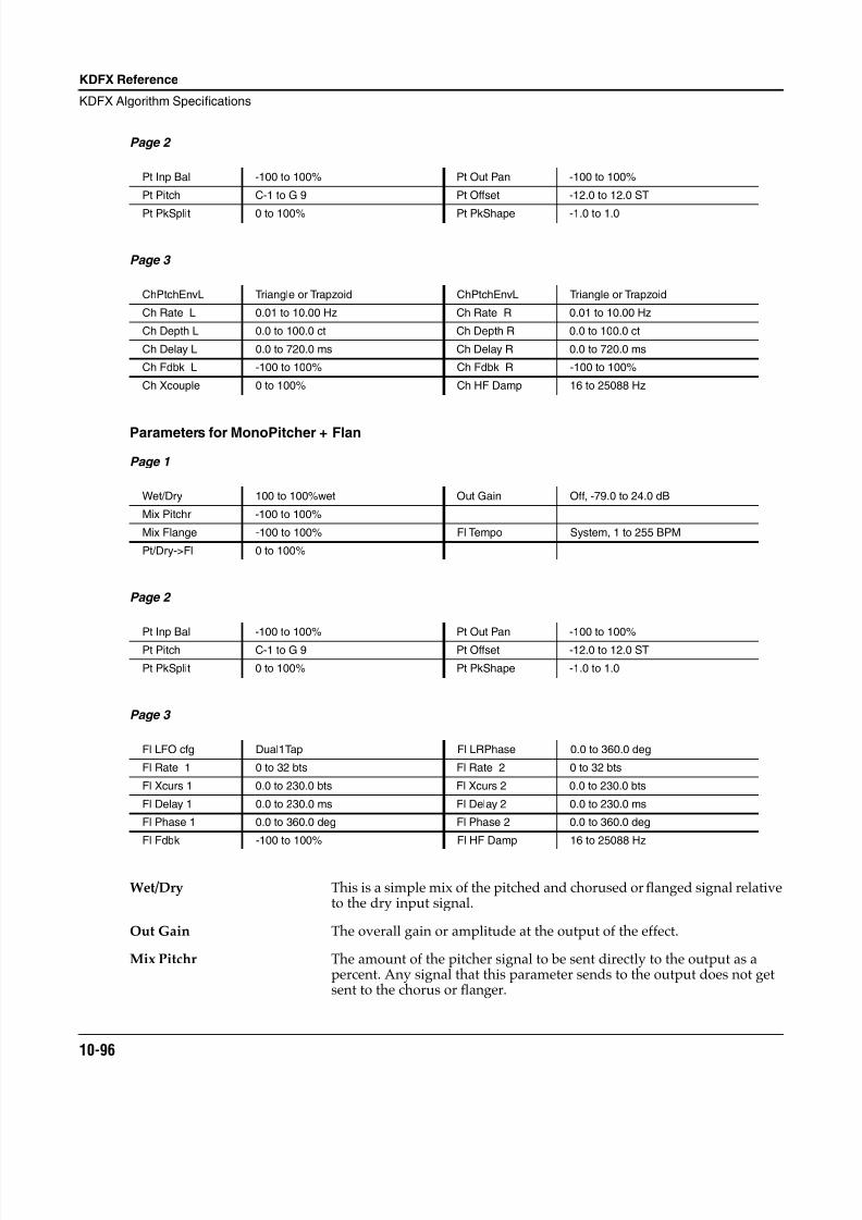
8/21/2019 MR_K2661
http://slidepdf.com/reader/full/mrk2661 178/499
10-96
KDFX Reference
KDFX Algorithm Specifications
Page 2
Page 3
Parameters for MonoPitcher + Flan
Page 1
Page 2
Page 3
Wet/Dry This is a simple mix of the pitched and chorused or flanged signal relativeto the dry input signal.
Out Gain The overall gain or amplitude at the output of the effect.
Mix Pitchr The amount of the pitcher signal to be sent directly to the output as apercent. Any signal that this parameter sends to the output does not getsent to the chorus or flanger.
Pt Inp Bal -100 to 100% Pt Out Pan -100 to 100%
Pt Pitch C-1 to G 9 Pt Offset -12.0 to 12.0 ST
Pt PkSplit 0 to 100% Pt PkShape -1.0 to 1.0
ChPtchEnvL Triangle or Trapzoid ChPtchEnvL Triangle or Trapzoid
Ch Rate L 0.01 to 10.00 Hz Ch Rate R 0.01 to 10.00 Hz
Ch Depth L 0.0 to 100.0 ct Ch Depth R 0.0 to 100.0 ct
Ch Delay L 0.0 to 720.0 ms Ch Delay R 0.0 to 720.0 ms
Ch Fdbk L -100 to 100% Ch Fdbk R -100 to 100%
Ch Xcouple 0 to 100% Ch HF Damp 16 to 25088 Hz
Wet/Dry 100 to 100%wet Out Gain Off, -79.0 to 24.0 dB
Mix Pitchr -100 to 100%
Mix Flange -100 to 100% Fl Tempo System, 1 to 255 BPM
Pt/Dry->Fl 0 to 100%
Pt Inp Bal -100 to 100% Pt Out Pan -100 to 100%
Pt Pitch C-1 to G 9 Pt Offset -12.0 to 12.0 ST
Pt PkSplit 0 to 100% Pt PkShape -1.0 to 1.0
Fl LFO cfg Dual1Tap Fl LRPhase 0.0 to 360.0 deg
Fl Rate 1 0 to 32 bts Fl Rate 2 0 to 32 bts
Fl Xcurs 1 0.0 to 230.0 bts Fl Xcurs 2 0.0 to 230.0 bts
Fl Delay 1 0.0 to 230.0 ms Fl Delay 2 0.0 to 230.0 ms
Fl Phase 1 0.0 to 360.0 deg Fl Phase 2 0.0 to 360.0 deg
Fl Fdbk -100 to 100% Fl HF Damp 16 to 25088 Hz
8/21/2019 MR_K2661
http://slidepdf.com/reader/full/mrk2661 179/499
KDFX Reference
KDFX Algorithm Specifications
10-97
Mix Chorus, Mix Flange The amount of the flanger or chorus signal to send to the output as apercent.
Pt/Dry->Ch, Pt/Dry->Fl The relative amount of pitcher signal to dry signal to send to the chorusor flanger. At 0% the dry input signal is routed to the chorus or flanger. At100%, the chorus or flanger receives its input entirely from the pitcher.
Pt Inp Bal Since this is a mono algorithm, an input balance control is provided tomix the left and right inputs to the pitcher. -100% is left only, 0% is leftplus right, and 100% is right only.
Pt Out Pan Pans the mono pitcher output from left (-100%) to center (0%) to right(100%)
Pt Pitch The "fundamental" frequency of the Pitcher output. This sets thefrequency of the lowest peak in terms of standard note names. All theother peaks will be at multiples of this pitch.
Pt PkSplit Splits the pitcher peaks into two peaks, which both move away from their
original unsplit position, one going up and the other down in frequency.At 0% there is no splitting; all peaks are at multiples of the fundamental.At 100% the peak going up merges with the peak going down from thenext higher position.
Pt Offset An offset in semitones from the frequency specified in Pitch.
Pt PkShape Controls the shape of the pitcher spectral peaks. 0.0 gives the most"pitchiness" to the output, in that the peaks are narrow, with not muchenergy between them. -1.0 makes the peaks wider. 1.0 brings up the level between the peaks.
All other Chorus parameters Refer to Chorus documentation.
Fl LFO cfg Sets the user interface mode for controlling each of the 4 flange LFOs.
Fl LRPhase Controls the relative phase between left channel LFOs and right channelLFOs. In Dual1Tap mode, however, this parameter is accurate only whenFl Rate 1 and Fl Rate 2 are set to the same speed, and only after the Fl LFOcfg parameter is moved, or the algorithm is called up.
Fl Phase 1, Fl Phase 2 These adjust the corresponding LFO phase relationships betweenthemselves and the internal beat clock.
All other Flange parameters Refer to Flange documentation. Parameters with a 1 or 2 correspond toLFO taps organized as described above.
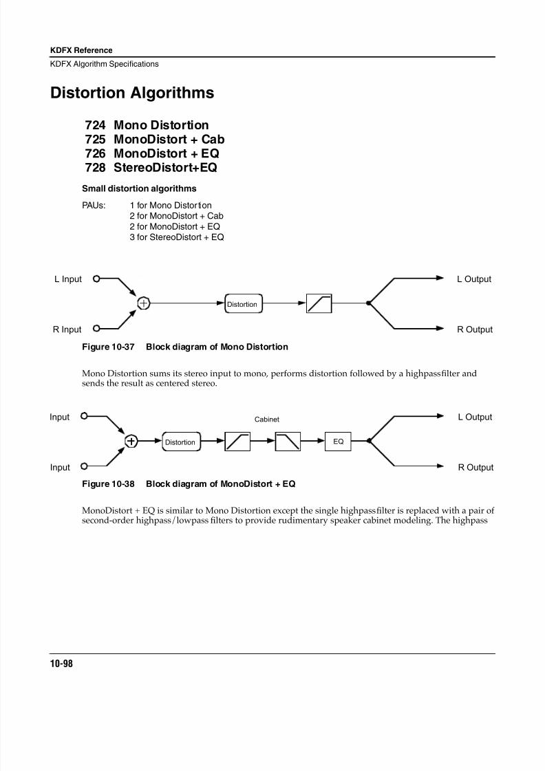
8/21/2019 MR_K2661
http://slidepdf.com/reader/full/mrk2661 180/499
10-98
KDFX Reference
KDFX Algorithm Specifications
Distortion Algorithms
724 Mono Distortion
725 MonoDistort + Cab726 MonoDistort + EQ728 StereoDistort+EQ
Small distortion algorithms
PAUs: 1 for Mono Distor tion2 for MonoDistort + Cab
2 for MonoDistort + EQ3 for StereoDistort + EQ
Figure 10-37 Block diagram of Mono Distortion
Mono Distortion sums its stereo input to mono, performs distortion followed by a highpass filter andsends the result as centered stereo.
Figure 10-38 Block diagram of MonoDistort + EQ
MonoDistort + EQ is similar to Mono Distortion except the single highpass filter is replaced with a pair ofsecond-order highpass/lowpass filters to provide rudimentary speaker cabinet modeling. The highpass
Distortion
L Output
R Output
L Input
R Input
Input
Input
Distortion
R Output
L Output
EQ
Cabinet
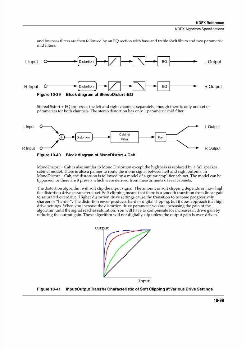
8/21/2019 MR_K2661
http://slidepdf.com/reader/full/mrk2661 181/499
KDFX Reference
KDFX Algorithm Specifications
10-99
and lowpass filters are then followed by an EQ section with bass and treble shelf filters and two parametricmid filters.
Figure 10-39 Block diagram of StereoDistort+EQ
StereoDistort + EQ processes the left and right channels separately, though there is only one set ofparameters for both channels. The stereo distortion has only 1 parametric mid filter.
Figure 10-40 Block diagram of MonoDistort + Cab
MonoDistort + Cab is also similar to Mono Distortion except the highpass is replaced by a full speakercabinet model. There is also a panner to route the mono signal between left and right outputs. InMonoDistort + Cab, the distortion is followed by a model of a guitar amplifier cabinet. The model can be bypassed, or there are 8 presets which were derived from measurments of real cabinets.
The distortion algorithm will soft clip the input signal. The amount of soft clipping depends on how highthe distortion drive parameter is set. Soft clipping means that there is a smooth transition from linear gainto saturated overdrive. Higher distortion drive settings cause the transition to become progressivelysharper or “harder”. The distortion never produces hard or digital clipping, but it does approach it at highdrive settings. When you increase the distortion drive parameter you are increasing the gain of thealgorithm until the signal reaches saturation. You will have to compensate for increases in drive gain byreducing the output gain. These algorithm will not digitally clip unless the output gain is over-driven.
Figure 10-41 Input/Output Transfer Characteristic of Soft Clipping at Various Drive Settings
Distortion EQ
Distortion EQ R Output
L OutputL Input
R Input
L Input
Distortion
R Input
Cabinet
Filter Pan
L Output
R Output
Output
Input
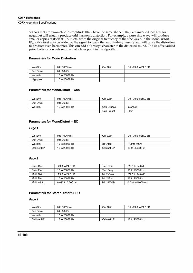
8/21/2019 MR_K2661
http://slidepdf.com/reader/full/mrk2661 182/499
10-100
KDFX Reference
KDFX Algorithm Specifications
Signals that are symmetric in amplitude (they have the same shape if they are inverted, positive fornegative) will usually produce odd harmonic distortion. For example, a pure sine wave will producesmaller copies of itself at 3, 5, 7, etc. times the original frequency of the sine wave. In the MonoDistort +EQ, a dc offset may be added to the signal to break the amplitude symmetry and will cause the distortionto produce even harmonics. This can add a “brassy” character to the distorted sound. The dc offset addedprior to distortion gets removed at a later point in the algorithm.
Parameters for Mono Distortion
Parameters for MonoDistort + Cab
Parameters for MonoDistort + EQ
Page 1
Page 2
Parameters for StereoDistort + EQ
Page 1
Wet/Dry 0 to 100%wet Out Gain Off, -79.0 to 24.0 dB
Dist Drive 0 to 96 dB
Warmth 16 to 25088 Hz
Highpass 16 to 25088 Hz
Wet/Dry 0 to 100%wet Out Gain Off, -79.0 to 24.0 dB
Dist Drive 0 to 96 dB
Warmth 16 to 25088 Hz Cab Bypass In or Out
Cab Preset Plain
Wet/Dry 0 to 100%wet Out Gain Off, -79.0 to 24.0 dB
Dist Drive 0 to 96 dB
Warmth 16 to 25088 Hz dc Offset -100 to 100%
Cabinet HP 16 to 25088 Hz Cabinet LP 16 to 25088 Hz
Bass Gain -79.0 to 24.0 dB Treb Gain -79.0 to 24.0 dB
Bass Freq 16 to 25088 Hz Treb Freq 16 to 25088 Hz
Mid1 Gain -79.0 to 24.0 dB Mid2 Gain -79.0 to 24.0 dB
Mid1 Freq 16 to 25088 Hz Mid2 Freq 16 to 25088 Hz
Mid1 Width 0.010 to 5.000 oct Mid2 Width 0.010 to 5.000 oct
Wet/Dry 0 to 100%wet Out Gain Off, -79.0 to 24.0 dB
Dist Drive 0 to 96 dB
Warmth 16 to 25088 Hz
Cabinet HP 16 to 25088 Hz Cabinet LP 16 to 25088 Hz
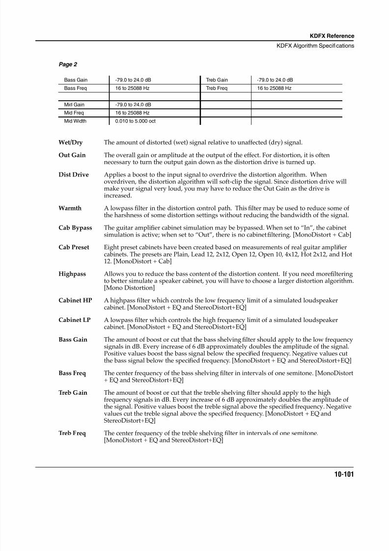
8/21/2019 MR_K2661
http://slidepdf.com/reader/full/mrk2661 183/499
KDFX Reference
KDFX Algorithm Specifications
10-101
Page 2
Wet/Dry The amount of distorted (wet) signal relative to unaffected (dry) signal.
Out Gain The overall gain or amplitude at the output of the effect. For distortion, it is oftennecessary to turn the output gain down as the distortion drive is turned up.
Dist Drive Applies a boost to the input signal to overdrive the distortion algorithm. Whenoverdriven, the distortion algorithm will soft-clip the signal. Since distortion drive willmake your signal very loud, you may have to reduce the Out Gain as the drive isincreased.
Warmth A lowpass filter in the distortion control path. This filter may be used to reduce some ofthe harshness of some distortion settings without reducing the bandwidth of the signal.
Cab Bypass The guitar amplifier cabinet simulation may be bypassed. When set to “In”, the cabinetsimulation is active; when set to “Out”, there is no cabinet filtering. [MonoDistort + Cab]
Cab Preset Eight preset cabinets have been created based on measurements of real guitar amplifiercabinets. The presets are Plain, Lead 12, 2x12, Open 12, Open 10, 4x12, Hot 2x12, and Hot12. [MonoDistort + Cab]
Highpass Allows you to reduce the bass content of the distortion content. If you need morefilteringto better simulate a speaker cabinet, you will have to choose a larger distortion algorithm.
[Mono Distortion]Cabinet HP A highpass filter which controls the low frequency limit of a simulated loudspeaker
cabinet. [MonoDistort + EQ and StereoDistort+EQ]
Cabinet LP A lowpass filter which controls the high frequency limit of a simulated loudspeakercabinet. [MonoDistort + EQ and StereoDistort+EQ]
Bass Gain The amount of boost or cut that the bass shelving filter should apply to the low frequencysignals in dB. Every increase of 6 dB approximately doubles the amplitude of the signal.Positive values boost the bass signal below the specified frequency. Negative values cutthe bass signal below the specified frequency. [MonoDistort + EQ and StereoDistort+EQ]
Bass Freq The center frequency of the bass shelving filter in intervals of one semitone. [MonoDistort+ EQ and StereoDistort+EQ]
Treb Gain The amount of boost or cut that the treble shelving filter should apply to the highfrequency signals in dB. Every increase of 6 dB approximately doubles the amplitude ofthe signal. Positive values boost the treble signal above the specified frequency. Negativevalues cut the treble signal above the specified frequency. [MonoDistort + EQ andStereoDistort+EQ]
Treb Freq The center frequency of the treble shelving filter in intervals of one semitone.[MonoDistort + EQ and StereoDistort+EQ]
Bass Gain -79.0 to 24.0 dB Treb Gain -79.0 to 24.0 dB
Bass Freq 16 to 25088 Hz Treb Freq 16 to 25088 Hz
Mid Gain -79.0 to 24.0 dB
Mid Freq 16 to 25088 Hz
Mid Width 0.010 to 5.000 oct
8/21/2019 MR_K2661
http://slidepdf.com/reader/full/mrk2661 184/499
10-102
KDFX Reference
KDFX Algorithm Specifications
Mid Gain The amount of boost or cut that the mid parametric filter should apply in dB. Everyincrease of 6 dB approximately doubles the amplitude of the signal. Positive values boostthe signal at the specified frequency. Negative values cut the signal at the specifiedfrequency. [MonoDistort + EQ and StereoDistort+EQ]
Mid Freq The center frequency of the mid parametric filter in intervals of one semitone. The boost orcut will be at a maximum at this frequency. [MonoDistort + EQ and StereoDistort+EQ]
Mid Wid The bandwidth of the mid parametric filter may be adjusted. You specify the bandwidthin octaves. Small values result in a very narrow filter response. Large values result in avery broad response. [MonoDistort + EQ and StereoDistort+EQ]
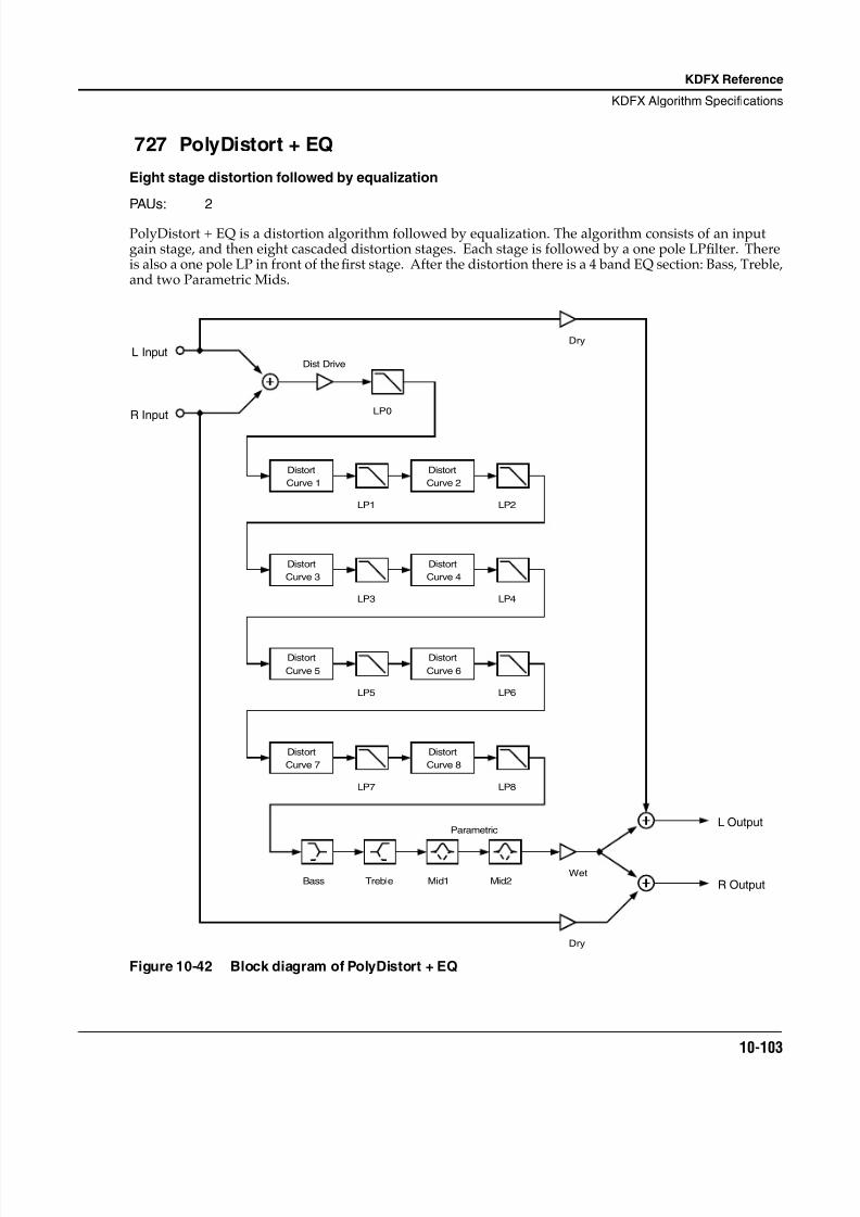
8/21/2019 MR_K2661
http://slidepdf.com/reader/full/mrk2661 185/499
KDFX Reference
KDFX Algorithm Specifications
10-103
727 PolyDistort + EQ
Eight stage distortion followed by equalization
PAUs: 2
PolyDistort + EQ is a distortion algorithm followed by equalization. The algorithm consists of an inputgain stage, and then eight cascaded distortion stages. Each stage is followed by a one pole LP filter. Thereis also a one pole LP in front of the first stage. After the distortion there is a 4 band EQ section: Bass, Treble,and two Parametric Mids.
Figure 10-42 Block diagram of PolyDistort + EQ
Distort
Curve 1 Curve 2
Distort
Curve 3
Distort Distort
Curve 4
Curve 5
Distort Distort
Curve 6
Curve 7
Distort Distort
Curve 8
L Input
R Input
L Output
R Output
Dry
Dry
Wet
LP1 LP2
LP3 LP4
LP5 LP6
LP7 LP8
Bass Treble Mid1 Mid2
Parametric
Dist Drive
LP0
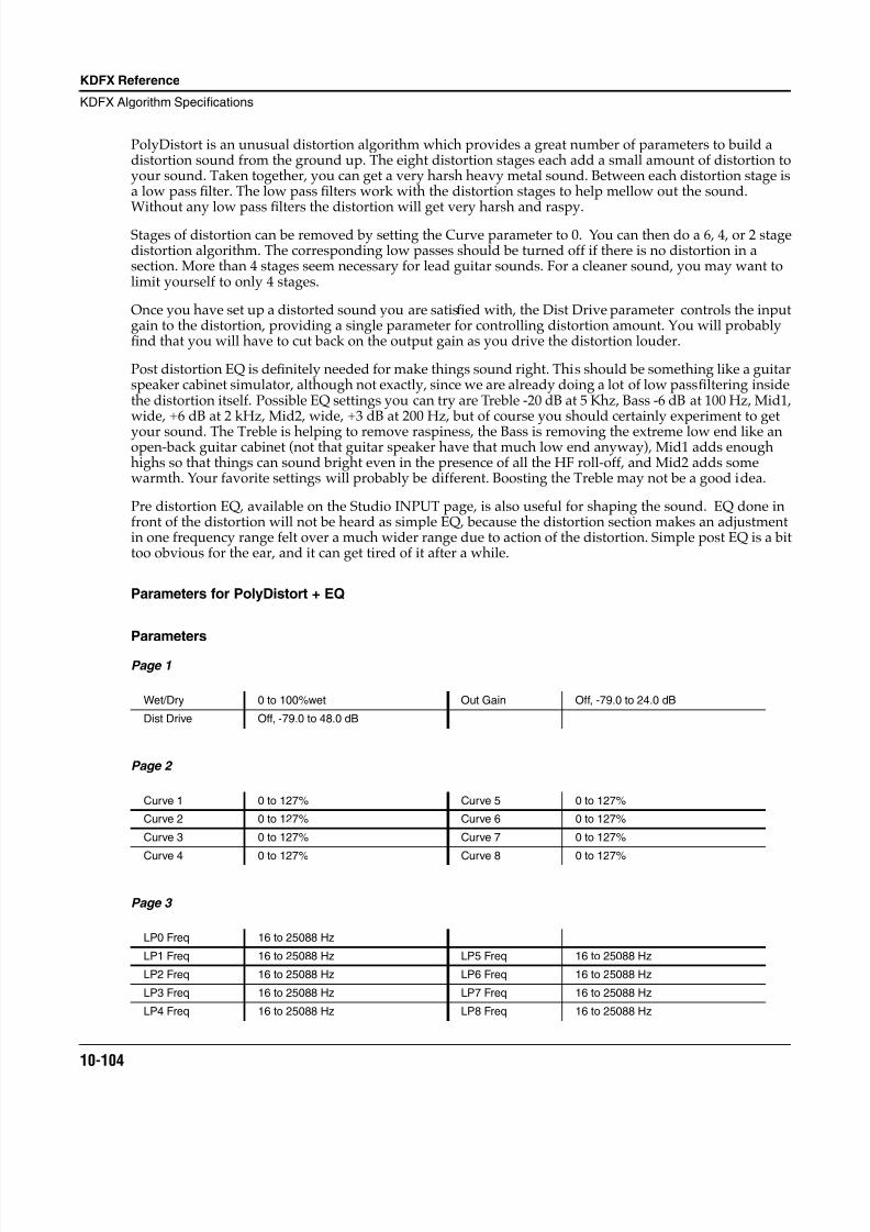
8/21/2019 MR_K2661
http://slidepdf.com/reader/full/mrk2661 186/499
10-104
KDFX Reference
KDFX Algorithm Specifications
PolyDistort is an unusual distortion algorithm which provides a great number of parameters to build adistortion sound from the ground up. The eight distortion stages each add a small amount of distortion toyour sound. Taken together, you can get a very harsh heavy metal sound. Between each distortion stage isa low pass filter. The low pass filters work with the distortion stages to help mellow out the sound.Without any low pass filters the distortion will get very harsh and raspy.
Stages of distortion can be removed by setting the Curve parameter to 0. You can then do a 6, 4, or 2 stagedistortion algorithm. The corresponding low passes should be turned off if there is no distortion in asection. More than 4 stages seem necessary for lead guitar sounds. For a cleaner sound, you may want tolimit yourself to only 4 stages.
Once you have set up a distorted sound you are satisfied with, the Dist Drive parameter controls the inputgain to the distortion, providing a single parameter for controlling distortion amount. You will probablyfind that you will have to cut back on the output gain as you drive the distortion louder.
Post distortion EQ is definitely needed for make things sound right. This should be something like a guitarspeaker cabinet simulator, although not exactly, since we are already doing a lot of low pass filtering insidethe distortion itself. Possible EQ settings you can try are Treble -20 dB at 5 Khz, Bass -6 dB at 100 Hz, Mid1,wide, +6 dB at 2 kHz, Mid2, wide, +3 dB at 200 Hz, but of course you should certainly experiment to get
your sound. The Treble is helping to remove raspiness, the Bass is removing the extreme low end like anopen-back guitar cabinet (not that guitar speaker have that much low end anyway), Mid1 adds enoughhighs so that things can sound bright even in the presence of all the HF roll-off, and Mid2 adds somewarmth. Your favorite settings will probably be different. Boosting the Treble may not be a good idea.
Pre distortion EQ, available on the Studio INPUT page, is also useful for shaping the sound. EQ done infront of the distortion will not be heard as simple EQ, because the distortion section makes an adjustmentin one frequency range felt over a much wider range due to action of the distortion. Simple post EQ is a bittoo obvious for the ear, and it can get tired of it after a while.
Parameters for PolyDistort + EQ
Parameters
Page 1
Page 2
Page 3
Wet/Dry 0 to 100%wet Out Gain Off, -79.0 to 24.0 dB
Dist Drive Off, -79.0 to 48.0 dB
Curve 1 0 to 127% Curve 5 0 to 127%
Curve 2 0 to 127% Curve 6 0 to 127%
Curve 3 0 to 127% Curve 7 0 to 127%
Curve 4 0 to 127% Curve 8 0 to 127%
LP0 Freq 16 to 25088 Hz
LP1 Freq 16 to 25088 Hz LP5 Freq 16 to 25088 Hz
LP2 Freq 16 to 25088 Hz LP6 Freq 16 to 25088 Hz
LP3 Freq 16 to 25088 Hz LP7 Freq 16 to 25088 Hz
LP4 Freq 16 to 25088 Hz LP8 Freq 16 to 25088 Hz
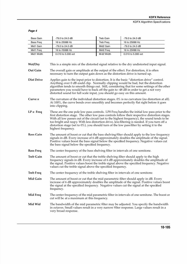
8/21/2019 MR_K2661
http://slidepdf.com/reader/full/mrk2661 187/499
KDFX Reference
KDFX Algorithm Specifications
10-105
Page 4
Wet/Dry This is a simple mix of the distorted signal relative to the dry undistorted input signal.
Out Gain The overall gain or amplitude at the output of the effect. For distortion, it is oftennecessary to turn the output gain down as the distortion drive is turned up.
Dist Drive Applies gain to the input prior to distortion. It is the basic “distortion drive” control.Anything over 0 dB could clip. Normally clipping would be bad, but the distortionalgorithm tends to smooth things out. Still, considering that for some settings of the otherparameters you would have to back off the gain to -48 dB in order to get a not very
distorted sound for full scale input, you should go easy on this amount.
Curve n The curvature of the individual distortion stages. 0% is no curvature (no distortion at all).At 100%, the curve bends over smoothly and becomes perfectly flat right before it goesinto clipping.
LP n Freq These are the one pole low pass controls. LP0 Freq handles the initial low pass prior to thefirst distortion stage. The other low pass controls follow their respective distortion stages.With all low passes out of the circuit (set to the highest frequency), the sound tends to betoo bright and raspy. With less distortion drive, less filtering is needed. If you turn off adistortion stage (set to 0%), you should turn of the low pass filter by setting it to thehighest frequency.
Bass Gain The amount of boost or cut that the bass shelving filter should apply to the low frequency
signals in dB. Every increase of 6 dB approximately doubles the amplitude of the signal.Positive values boost the bass signal below the specified frequency. Negative values cutthe bass signal below the specified frequency.
Bass Freq The center frequency of the bass shelving filter in intervals of one semitone.
Treb Gain The amount of boost or cut that the treble shelving filter should apply to the highfrequency signals in dB. Every increase of 6 dB approximately doubles the amplitude ofthe signal. Positive values boost the treble signal above the specified frequency. Negativevalues cut the treble signal above the specified frequency.
Treb Freq The center frequency of the treble shelving filter in intervals of one semitone.
Mid Gain The amount of boost or cut that the mid parametric filter should apply in dB. Everyincrease of 6 dB approximately doubles the amplitude of the signal. Positive values boost
the signal at the specified frequency. Negative values cut the signal at the specifiedfrequency.
Mid Freq The center frequency of the mid parametric filter in intervals of one semitone. The boost orcut will be at a maximum at this frequency.
Mid Wid The bandwidth of the mid parametric filter may be adjusted. You specify the bandwidthin octaves. Small values result in a very narrow filter response. Large values result in avery broad response.
Bass Gain -79.0 to 24.0 dB Treb Gain -79.0 to 24.0 dB
Bass Freq 16 to 25088 Hz Treb Freq 16 to 25088 Hz
Mid1 Gain -79.0 to 24.0 dB Mid2 Gain -79.0 to 24.0 dBMid1 Freq 16 to 25088 Hz Mid2 Freq 16 to 25088 Hz
Mid1 Width 0.010 to 5.000 oct Mid2 Width 0.010 to 5.000 oct
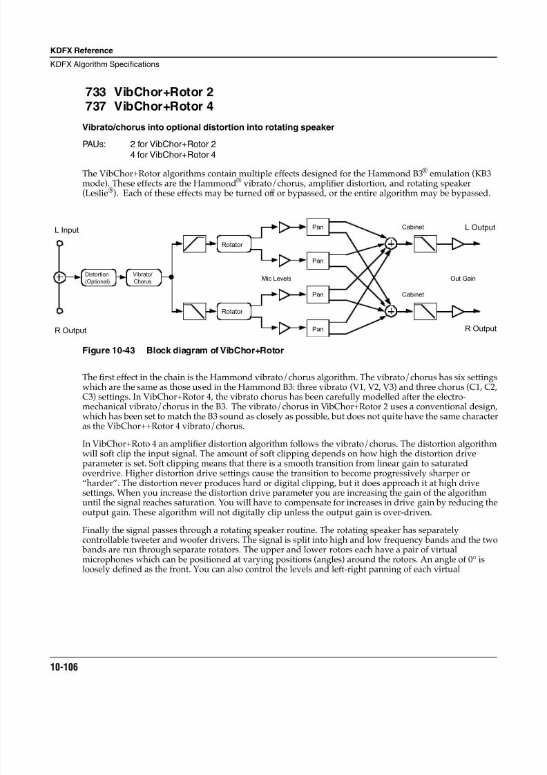
8/21/2019 MR_K2661
http://slidepdf.com/reader/full/mrk2661 188/499
10-106
KDFX Reference
KDFX Algorithm Specifications
733 VibChor+Rotor 2737 VibChor+Rotor 4
Vibrato/chorus into optional distortion into rotating speaker
PAUs: 2 for VibChor+Rotor 24 for VibChor+Rotor 4
The VibChor+Rotor algorithms contain multiple effects designed for the Hammond B3® emulation (KB3mode). These effects are the Hammond® vibrato/chorus, amplifier distortion, and rotating speaker(Leslie®). Each of these effects may be turned off or bypassed, or the entire algorithm may be bypassed.
Figure 10-43 Block diagram of VibChor+Rotor
The first effect in the chain is the Hammond vibrato/chorus algorithm. The vibrato/chorus has six settingswhich are the same as those used in the Hammond B3: three vibrato (V1, V2, V3) and three chorus (C1, C2,C3) settings. In VibChor+Rotor 4, the vibrato chorus has been carefully modelled after the electro-
mechanical vibrato/chorus in the B3. The vibrato/chorus in VibChor+Rotor 2 uses a conventional design,which has been set to match the B3 sound as closely as possible, but does not quite have the same characteras the VibChor++Rotor 4 vibrato/chorus.
In VibChor+Roto 4 an amplifier distortion algorithm follows the vibrato/chorus. The distortion algorithmwill soft clip the input signal. The amount of soft clipping depends on how high the distortion driveparameter is set. Soft clipping means that there is a smooth transition from linear gain to saturatedoverdrive. Higher distortion drive settings cause the transition to become progressively sharper or“harder”. The distortion never produces hard or digital clipping, but it does approach it at high drivesettings. When you increase the distortion drive parameter you are increasing the gain of the algorithmuntil the signal reaches saturation. You will have to compensate for increases in drive gain by reducing theoutput gain. These algorithm will not digitally clip unless the output gain is over-driven.
Finally the signal passes through a rotating speaker routine. The rotating speaker has separately
controllable tweeter and woofer drivers. The signal is split into high and low frequency bands and the two bands are run through separate rotators. The upper and lower rotors each have a pair of virtualmicrophones which can be positioned at varying positions (angles) around the rotors. An angle of 0° isloosely defined as the front. You can also control the levels and left-right panning of each virtual
Pan
Pan
Pan
Pan
L Output
R Output
Mic Levels Out Gain
Cabinet
Cabinet
Rotator
Rotator
Vibrato/
Chorus
Distortion
(Optional)
L Input
R Output
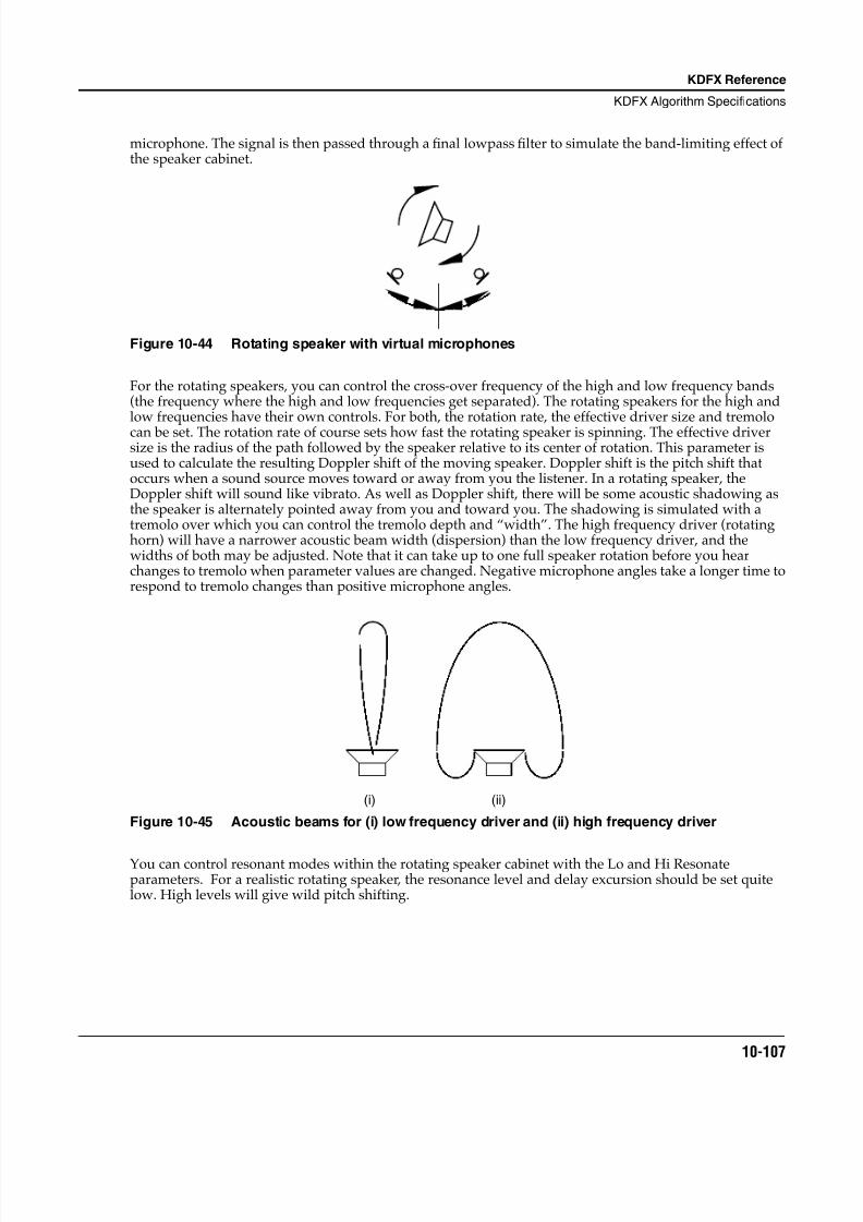
8/21/2019 MR_K2661
http://slidepdf.com/reader/full/mrk2661 189/499
KDFX Reference
KDFX Algorithm Specifications
10-107
microphone. The signal is then passed through a final lowpass filter to simulate the band-limiting effect ofthe speaker cabinet.
Figure 10-44 Rotating speaker with virtual microphones
For the rotating speakers, you can control the cross-over frequency of the high and low frequency bands(the frequency where the high and low frequencies get separated). The rotating speakers for the high andlow frequencies have their own controls. For both, the rotation rate, the effective driver size and tremolocan be set. The rotation rate of course sets how fast the rotating speaker is spinning. The effective driversize is the radius of the path followed by the speaker relative to its center of rotation. This parameter isused to calculate the resulting Doppler shift of the moving speaker. Doppler shift is the pitch shift thatoccurs when a sound source moves toward or away from you the listener. In a rotating speaker, theDoppler shift will sound like vibrato. As well as Doppler shift, there will be some acoustic shadowing asthe speaker is alternately pointed away from you and toward you. The shadowing is simulated with atremolo over which you can control the tremolo depth and “width”. The high frequency driver (rotatinghorn) will have a narrower acoustic beam width (dispersion) than the low frequency driver, and thewidths of both may be adjusted. Note that it can take up to one full speaker rotation before you hearchanges to tremolo when parameter values are changed. Negative microphone angles take a longer time torespond to tremolo changes than positive microphone angles.
Figure 10-45 Acoustic beams for (i) low frequency driver and (ii) high frequency driver
You can control resonant modes within the rotating speaker cabinet with the Lo and Hi Resonateparameters. For a realistic rotating speaker, the resonance level and delay excursion should be set quitelow. High levels will give wild pitch shifting.
(i) (ii)
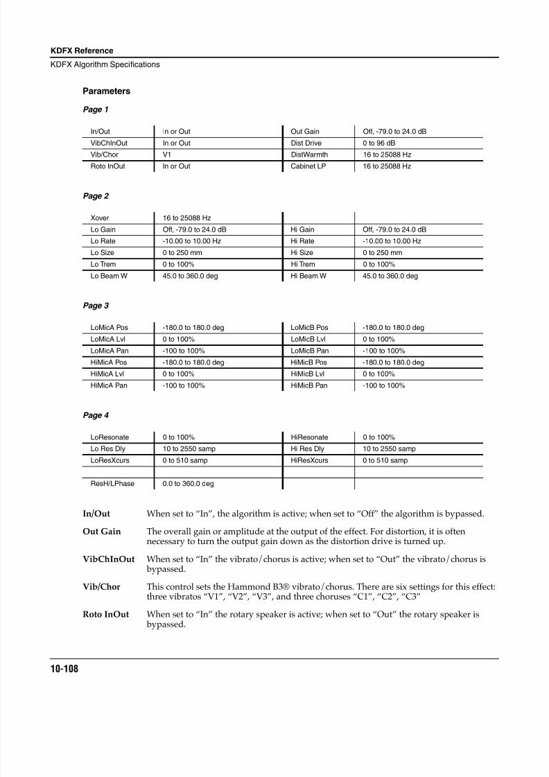
8/21/2019 MR_K2661
http://slidepdf.com/reader/full/mrk2661 190/499
10-108
KDFX Reference
KDFX Algorithm Specifications
Parameters
Page 1
Page 2
Page 3
Page 4
In/Out When set to “In”, the algorithm is active; when set to “Off” the algorithm is bypassed.
Out Gain The overall gain or amplitude at the output of the effect. For distortion, it is often
necessary to turn the output gain down as the distortion drive is turned up.VibChInOut When set to “In” the vibrato/chorus is active; when set to “Out” the vibrato/chorus is
bypassed.
Vib/Chor This control sets the Hammond B3® vibrato/chorus. There are six settings for this effect:three vibratos “V1”, “V2”, “V3”, and three choruses “C1”, “C2”, “C3”
Roto InOut When set to “In” the rotary speaker is active; when set to “Out” the rotary speaker is bypassed.
In/Out In or Out Out Gain Off, -79.0 to 24.0 dB
VibChInOut In or Out Dist Drive 0 to 96 dB
Vib/Chor V1 DistWarmth 16 to 25088 Hz
Roto InOut In or Out Cabinet LP 16 to 25088 Hz
Xover 16 to 25088 Hz
Lo Gain Off, -79.0 to 24.0 dB Hi Gain Off, -79.0 to 24.0 dB
Lo Rate -10.00 to 10.00 Hz Hi Rate -10.00 to 10.00 Hz
Lo Size 0 to 250 mm Hi Size 0 to 250 mm
Lo Trem 0 to 100% Hi Trem 0 to 100%
Lo Beam W 45.0 to 360.0 deg Hi Beam W 45.0 to 360.0 deg
LoMicA Pos -180.0 to 180.0 deg LoMicB Pos -180.0 to 180.0 deg
LoMicA Lvl 0 to 100% LoMicB Lvl 0 to 100%
LoMicA Pan -100 to 100% LoMicB Pan -100 to 100%
HiMicA Pos -180.0 to 180.0 deg HiMicB Pos -180.0 to 180.0 deg
HiMicA Lvl 0 to 100% HiMicB Lvl 0 to 100%
HiMicA Pan -100 to 100% HiMicB Pan -100 to 100%
LoResonate 0 to 100% HiResonate 0 to 100%
Lo Res Dly 10 to 2550 samp Hi Res Dly 10 to 2550 samp
LoResXcurs 0 to 510 samp HiResXcurs 0 to 510 samp
ResH/LPhase 0.0 to 360.0 deg
8/21/2019 MR_K2661
http://slidepdf.com/reader/full/mrk2661 191/499
KDFX Reference
KDFX Algorithm Specifications
10-109
Dist Drive Applies a boost to the input signal to overdrive the distortion algorithm. Whenoverdriven, the distortion algorithm will soft-clip the signal. Since distortion drive willmake your signal very loud, you may have to reduce the Out Gain as the drive isincreased. [VibChor+Rotor 4 only]
DistWarmth A lowpass filter in the distortion control path. This filter may be used to reduce some ofthe harshness of some distortion settings without reducing the bandwidth of the signal.[VibChor+Rotor 4 only]
Cabinet LP A lowpass filter to simulate the band-limiting of a speaker cabinet. The filter controls theupper frequency limit of the output.
Xover The frequency at which high and low frequency bands are split and sent to separaterotating drivers.
Lo Gain The gain or amplitude of the signal passing through the rotating woofer (low frequencydriver.
Lo Rate The rotation rate of the rotating woofer (low frequency driver). The woofer can rotate
clockwise or counter-clockwise. The direction of rotation depends on the sign of the rateparameter. Assuming microphone angles are set toward the front (between -90° and 90°)and microphones at positive angles are panned to the right (positive pan values), thenpositive rates correspond to clockwise rotation when viewed from the top.
Lo Size The effective size (radius of rotation) of the rotating woofer in millimeters. Affects theamount of Doppler shift or vibrato of the low frequency signal.
Lo Trem Controls the depth of tremolo of the low frequency signal. Expressed as a percentage offull scale tremolo.
Lo Beam W The rotating speaker effect attempts to model a rotating woofer for the low frequencydriver. The acoustic radiation pattern of a woofer tends to range from omnidirectional(radiates in directions in equal amounts) to a wide beam. You may adjust the beam widthfrom 45° to 360°. If you imagine looking down on the rotating speaker, the beam angle is
the angle between the -6 dB levels of the beam. At 360°, the woofer is omnidirectional.
Hi Gain The gain or amplitude of the signal passing through the rotating tweeter (high frequencydriver.
Hi Rate The rotation rate of the rotating tweeter (high frequency driver). The tweeter can rotateclockwise or counter-clockwise. The direction of rotation depends on the sign of the rateparameter. Assuming microphone angles are set toward the front (between -90° and 90°)and microphones at positive angles are panned to the right (positive pan values), thenpositive rates correspond to clockwise rotation when viewed from the top.
Hi Size The effective size (radius of rotation) of the rotating tweeter in millimeters. Affects theamount of Doppler shift or vibrato of the high frequency signal.
Hi Trem Controls the depth of tremolo of the high frequency signal. Expressed as a percentage offull scale tremolo.
Hi Beam W The rotating speaker effect attempts to model a rotating horn for the high frequencydriver. The acoustic radiation pattern of a horn tends to be a narrow beam. You may adjustthe beam width from 45° to 360°. If you imagine looking down on the rotating speaker, the beam angle is the angle between the -6 dB levels of the beam. At 360°, the horn isomnidirectional (radiates in all directions equally).
Mic Pos The angle of the virtual microphones in degrees from the “front” of the rotating speaker.This parameter is not well suited to modulation because adjustments to it will result in
8/21/2019 MR_K2661
http://slidepdf.com/reader/full/mrk2661 192/499
10-110
KDFX Reference
KDFX Algorithm Specifications
large sample skips (audible as clicks when signal is passing through the effect). There arefour of these parameters to include 2 pairs (A and B) for high and low frequency drivers.
Mic Lvl The level of the virtual microphone signal being sent to the output. There are four of theseparameters to include 2 pairs (A and B) for high and low frequency drivers.
Mic Pan Left-right panning of the virtual microphone signals. A settings of -100% is panned fullyleft, and 100% is panned fully right. There are four of these parameters to include 2 pairs(A and B) for high and low frequency drivers.
LoResonate A simulation of cabinet resonant modes express as a percentage. For realism, you shoulduse very low settings. This is for the low frequency signal path.
Lo Res Dly The number of samples of delay in the resonator circuit in addition to the rotationexcursion delay. This is for the low frequency signal path.
LoResXcurs The number of samples of delay to sweep through the resonator at the rotation rate of therotating speaker. This is for the low frequency signal path.
HiResonate A simulation of cabinet resonant modes express as a percentage. For realism, you shoulduse very low settings. This is for the high frequency signal path.
Hi Res Dly The number of samples of delay in the resonator circuit in addition to the rotationexcursion delay. This is for the high frequency signal path.
HiResXcurs The number of samples of delay to sweep through the resonator at the rotation rate of therotating speaker. This is for the high frequency signal path.
ResH/LPhs This parameter sets the relative phases of the high and low resonators. The angle value indegrees is somewhat arbitrary and you can expect the effect of this parameter to be rathersubtle.
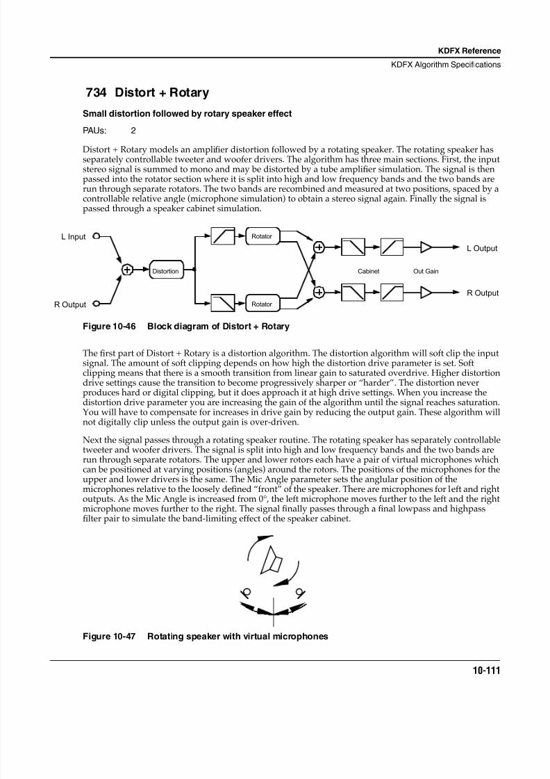
8/21/2019 MR_K2661
http://slidepdf.com/reader/full/mrk2661 193/499
KDFX Reference
KDFX Algorithm Specifications
10-111
734 Distort + Rotary
Small distortion followed by rotary speaker effect
PAUs: 2
Distort + Rotary models an amplifier distortion followed by a rotating speaker. The rotating speaker hasseparately controllable tweeter and woofer drivers. The algorithm has three main sections. First, the inputstereo signal is summed to mono and may be distorted by a tube amplifier simulation. The signal is thenpassed into the rotator section where it is split into high and low frequency bands and the two bands arerun through separate rotators. The two bands are recombined and measured at two positions, spaced by acontrollable relative angle (microphone simulation) to obtain a stereo signal again. Finally the signal ispassed through a speaker cabinet simulation.
Figure 10-46 Block diagram of Distort + Rotary
The first part of Distort + Rotary is a distortion algorithm. The distortion algorithm will soft clip the inputsignal. The amount of soft clipping depends on how high the distortion drive parameter is set. Softclipping means that there is a smooth transition from linear gain to saturated overdrive. Higher distortiondrive settings cause the transition to become progressively sharper or “harder”. The distortion neverproduces hard or digital clipping, but it does approach it at high drive settings. When you increase thedistortion drive parameter you are increasing the gain of the algorithm until the signal reaches saturation.You will have to compensate for increases in drive gain by reducing the output gain. These algorithm willnot digitally clip unless the output gain is over-driven.
Next the signal passes through a rotating speaker routine. The rotating speaker has separately controllabletweeter and woofer drivers. The signal is split into high and low frequency bands and the two bands arerun through separate rotators. The upper and lower rotors each have a pair of virtual microphones whichcan be positioned at varying positions (angles) around the rotors. The positions of the microphones for theupper and lower drivers is the same. The Mic Angle parameter sets the anglular position of themicrophones relative to the loosely defined “front” of the speaker. There are microphones for left and rightoutputs. As the Mic Angle is increased from 0°, the left microphone moves further to the left and the rightmicrophone moves further to the right. The signal finally passes through a final lowpass and highpassfilter pair to simulate the band-limiting effect of the speaker cabinet.
Figure 10-47 Rotating speaker with virtual microphones
Distortion
Rotator
Rotator
L Input
R Output
L Output
R Output
Out GainCabinet
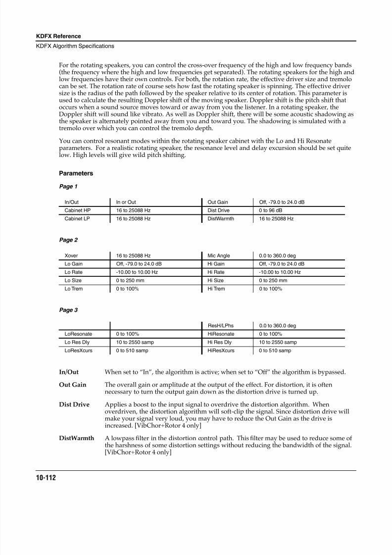
8/21/2019 MR_K2661
http://slidepdf.com/reader/full/mrk2661 194/499
10-112
KDFX Reference
KDFX Algorithm Specifications
For the rotating speakers, you can control the cross-over frequency of the high and low frequency bands(the frequency where the high and low frequencies get separated). The rotating speakers for the high andlow frequencies have their own controls. For both, the rotation rate, the effective driver size and tremolocan be set. The rotation rate of course sets how fast the rotating speaker is spinning. The effective driversize is the radius of the path followed by the speaker relative to its center of rotation. This parameter isused to calculate the resulting Doppler shift of the moving speaker. Doppler shift is the pitch shift thatoccurs when a sound source moves toward or away from you the listener. In a rotating speaker, theDoppler shift will sound like vibrato. As well as Doppler shift, there will be some acoustic shadowing asthe speaker is alternately pointed away from you and toward you. The shadowing is simulated with atremolo over which you can control the tremolo depth.
You can control resonant modes within the rotating speaker cabinet with the Lo and Hi Resonateparameters. For a realistic rotating speaker, the resonance level and delay excursion should be set quitelow. High levels will give wild pitch shifting.
Parameters
Page 1
Page 2
Page 3
In/Out When set to “In”, the algorithm is active; when set to “Off” the algorithm is bypassed.
Out Gain The overall gain or amplitude at the output of the effect. For distortion, it is oftennecessary to turn the output gain down as the distortion drive is turned up.
Dist Drive Applies a boost to the input signal to overdrive the distortion algorithm. Whenoverdriven, the distortion algorithm will soft-clip the signal. Since distortion drive willmake your signal very loud, you may have to reduce the Out Gain as the drive isincreased. [VibChor+Rotor 4 only]
DistWarmth A lowpass filter in the distortion control path. This filter may be used to reduce some ofthe harshness of some distortion settings without reducing the bandwidth of the signal.[VibChor+Rotor 4 only]
In/Out In or Out Out Gain Off, -79.0 to 24.0 dB
Cabinet HP 16 to 25088 Hz Dist Drive 0 to 96 dB
Cabinet LP 16 to 25088 Hz DistWarmth 16 to 25088 Hz
Xover 16 to 25088 Hz Mic Angle 0.0 to 360.0 deg
Lo Gain Off, -79.0 to 24.0 dB Hi Gain Off, -79.0 to 24.0 dB
Lo Rate -10.00 to 10.00 Hz Hi Rate -10.00 to 10.00 Hz
Lo Size 0 to 250 mm Hi Size 0 to 250 mm
Lo Trem 0 to 100% Hi Trem 0 to 100%
ResH/LPhs 0.0 to 360.0 deg
LoResonate 0 to 100% HiResonate 0 to 100%
Lo Res Dly 10 to 2550 samp Hi Res Dly 10 to 2550 samp
LoResXcurs 0 to 510 samp HiResXcurs 0 to 510 samp
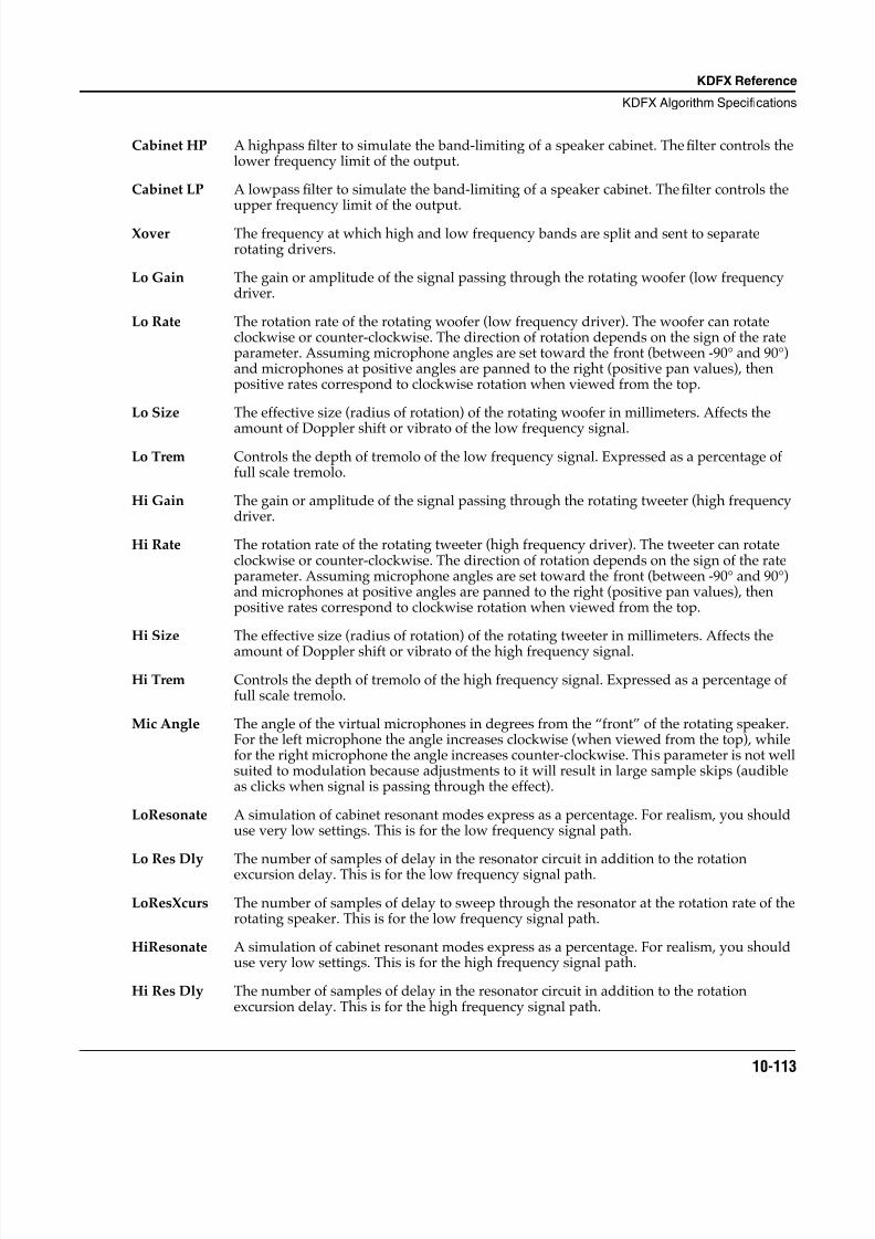
8/21/2019 MR_K2661
http://slidepdf.com/reader/full/mrk2661 195/499
KDFX Reference
KDFX Algorithm Specifications
10-113
Cabinet HP A highpass filter to simulate the band-limiting of a speaker cabinet. The filter controls thelower frequency limit of the output.
Cabinet LP A lowpass filter to simulate the band-limiting of a speaker cabinet. The filter controls theupper frequency limit of the output.
Xover The frequency at which high and low frequency bands are split and sent to separaterotating drivers.
Lo Gain The gain or amplitude of the signal passing through the rotating woofer (low frequencydriver.
Lo Rate The rotation rate of the rotating woofer (low frequency driver). The woofer can rotateclockwise or counter-clockwise. The direction of rotation depends on the sign of the rateparameter. Assuming microphone angles are set toward the front (between -90° and 90°)and microphones at positive angles are panned to the right (positive pan values), thenpositive rates correspond to clockwise rotation when viewed from the top.
Lo Size The effective size (radius of rotation) of the rotating woofer in millimeters. Affects the
amount of Doppler shift or vibrato of the low frequency signal.Lo Trem Controls the depth of tremolo of the low frequency signal. Expressed as a percentage of
full scale tremolo.
Hi Gain The gain or amplitude of the signal passing through the rotating tweeter (high frequencydriver.
Hi Rate The rotation rate of the rotating tweeter (high frequency driver). The tweeter can rotateclockwise or counter-clockwise. The direction of rotation depends on the sign of the rateparameter. Assuming microphone angles are set toward the front (between -90° and 90°)and microphones at positive angles are panned to the right (positive pan values), thenpositive rates correspond to clockwise rotation when viewed from the top.
Hi Size The effective size (radius of rotation) of the rotating tweeter in millimeters. Affects the
amount of Doppler shift or vibrato of the high frequency signal.
Hi Trem Controls the depth of tremolo of the high frequency signal. Expressed as a percentage offull scale tremolo.
Mic Angle The angle of the virtual microphones in degrees from the “front” of the rotating speaker.For the left microphone the angle increases clockwise (when viewed from the top), whilefor the right microphone the angle increases counter-clockwise. This parameter is not wellsuited to modulation because adjustments to it will result in large sample skips (audibleas clicks when signal is passing through the effect).
LoResonate A simulation of cabinet resonant modes express as a percentage. For realism, you shoulduse very low settings. This is for the low frequency signal path.
Lo Res Dly The number of samples of delay in the resonator circuit in addition to the rotationexcursion delay. This is for the low frequency signal path.
LoResXcurs The number of samples of delay to sweep through the resonator at the rotation rate of therotating speaker. This is for the low frequency signal path.
HiResonate A simulation of cabinet resonant modes express as a percentage. For realism, you shoulduse very low settings. This is for the high frequency signal path.
Hi Res Dly The number of samples of delay in the resonator circuit in addition to the rotationexcursion delay. This is for the high frequency signal path.
8/21/2019 MR_K2661
http://slidepdf.com/reader/full/mrk2661 196/499
10-114
KDFX Reference
KDFX Algorithm Specifications
HiResXcurs The number of samples of delay to sweep through the resonator at the rotation rate of therotating speaker. This is for the high frequency signal path.
ResH/LPhs This parameter sets the relative phases of the high and low resonators. The angle value indegrees is somewhat arbitrary and you can expect the effect of this parameter to be rathersubtle.
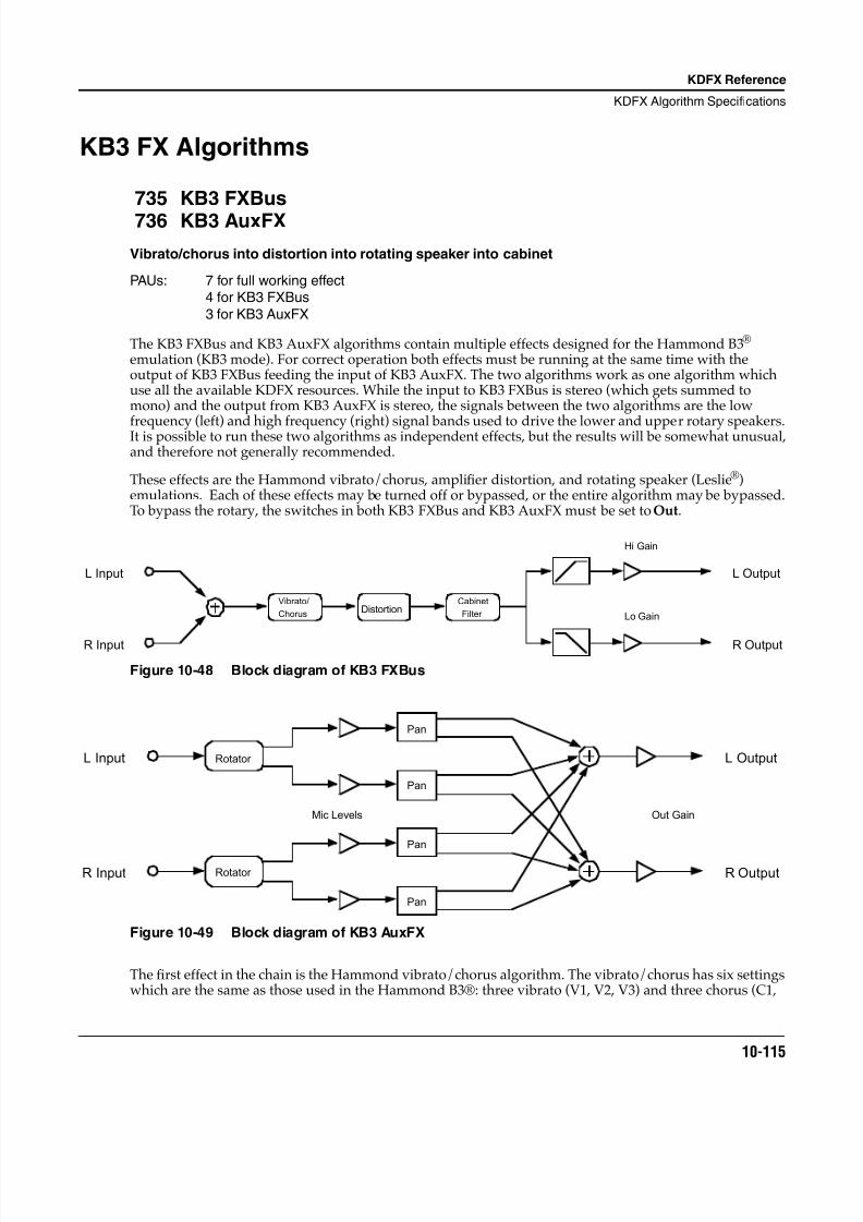
8/21/2019 MR_K2661
http://slidepdf.com/reader/full/mrk2661 197/499
KDFX Reference
KDFX Algorithm Specifications
10-115
KB3 FX Algorithms
735 KB3 FXBus
736 KB3 AuxFX
Vibrato/chorus into distortion into rotating speaker into cabinet
PAUs: 7 for full working effect4 for KB3 FXBus
3 for KB3 AuxFX
The KB3 FXBus and KB3 AuxFX algorithms contain multiple effects designed for the Hammond B3®
emulation (KB3 mode). For correct operation both effects must be running at the same time with theoutput of KB3 FXBus feeding the input of KB3 AuxFX. The two algorithms work as one algorithm whichuse all the available KDFX resources. While the input to KB3 FXBus is stereo (which gets summed tomono) and the output from KB3 AuxFX is stereo, the signals between the two algorithms are the low
frequency (left) and high frequency (right) signal bands used to drive the lower and upper rotary speakers.It is possible to run these two algorithms as independent effects, but the results will be somewhat unusual,and therefore not generally recommended.
These effects are the Hammond vibrato/chorus, amplifier distortion, and rotating speaker (Leslie®)emulations. Each of these effects may be turned off or bypassed, or the entire algorithm may be bypassed.To bypass the rotary, the switches in both KB3 FXBus and KB3 AuxFX must be set to Out.
Figure 10-48 Block diagram of KB3 FXBus
Figure 10-49 Block diagram of KB3 AuxFX
The first effect in the chain is the Hammond vibrato/chorus algorithm. The vibrato/chorus has six settingswhich are the same as those used in the Hammond B3®: three vibrato (V1, V2, V3) and three chorus (C1,
Vibrato/
ChorusDistortion
Cabinet
Filter
L Input
R Input
L Output
R Output
Hi Gain
Lo Gain
Rotator
Rotator
Pan
Pan
Pan
Pan
L Input
R Input
L Output
R Output
Mic Levels Out Gain
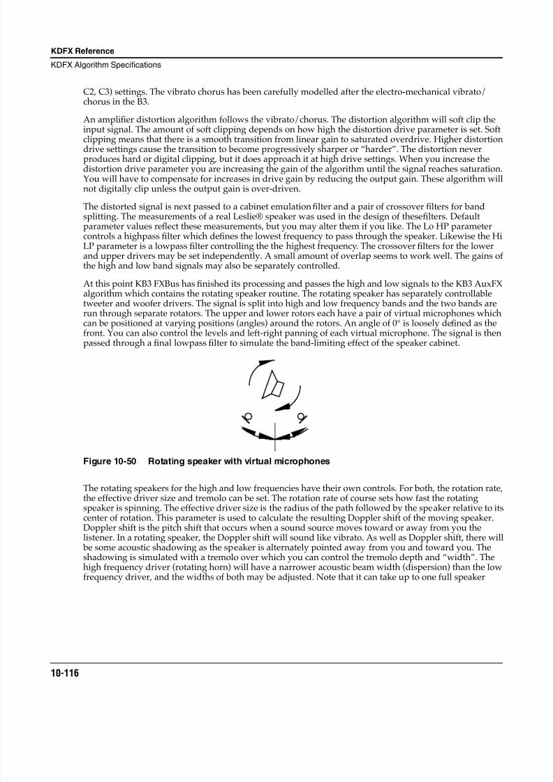
8/21/2019 MR_K2661
http://slidepdf.com/reader/full/mrk2661 198/499
10-116
KDFX Reference
KDFX Algorithm Specifications
C2, C3) settings. The vibrato chorus has been carefully modelled after the electro-mechanical vibrato/chorus in the B3.
An amplifier distortion algorithm follows the vibrato/chorus. The distortion algorithm will soft clip theinput signal. The amount of soft clipping depends on how high the distortion drive parameter is set. Softclipping means that there is a smooth transition from linear gain to saturated overdrive. Higher distortiondrive settings cause the transition to become progressively sharper or “harder”. The distortion neverproduces hard or digital clipping, but it does approach it at high drive settings. When you increase thedistortion drive parameter you are increasing the gain of the algorithm until the signal reaches saturation.You will have to compensate for increases in drive gain by reducing the output gain. These algorithm willnot digitally clip unless the output gain is over-driven.
The distorted signal is next passed to a cabinet emulation filter and a pair of crossover filters for bandsplitting. The measurements of a real Leslie® speaker was used in the design of these filters. Defaultparameter values reflect these measurements, but you may alter them if you like. The Lo HP parametercontrols a highpass filter which defines the lowest frequency to pass through the speaker. Likewise the HiLP parameter is a lowpass filter controlling the the highest frequency. The crossover filters for the lowerand upper drivers may be set independently. A small amount of overlap seems to work well. The gains ofthe high and low band signals may also be separately controlled.
At this point KB3 FXBus has finished its processing and passes the high and low signals to the KB3 AuxFXalgorithm which contains the rotating speaker routine. The rotating speaker has separately controllabletweeter and woofer drivers. The signal is split into high and low frequency bands and the two bands arerun through separate rotators. The upper and lower rotors each have a pair of virtual microphones whichcan be positioned at varying positions (angles) around the rotors. An angle of 0° is loosely defined as thefront. You can also control the levels and left-right panning of each virtual microphone. The signal is thenpassed through a final lowpass filter to simulate the band-limiting effect of the speaker cabinet.
Figure 10-50 Rotating speaker with virtual microphones
The rotating speakers for the high and low frequencies have their own controls. For both, the rotation rate,the effective driver size and tremolo can be set. The rotation rate of course sets how fast the rotatingspeaker is spinning. The effective driver size is the radius of the path followed by the speaker relative to itscenter of rotation. This parameter is used to calculate the resulting Doppler shift of the moving speaker.Doppler shift is the pitch shift that occurs when a sound source moves toward or away from you thelistener. In a rotating speaker, the Doppler shift will sound like vibrato. As well as Doppler shift, there will
be some acoustic shadowing as the speaker is alternately pointed away from you and toward you. Theshadowing is simulated with a tremolo over which you can control the tremolo depth and “width”. Thehigh frequency driver (rotating horn) will have a narrower acoustic beam width (dispersion) than the lowfrequency driver, and the widths of both may be adjusted. Note that it can take up to one full speaker
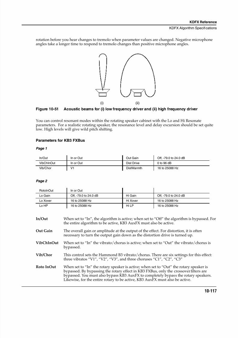
8/21/2019 MR_K2661
http://slidepdf.com/reader/full/mrk2661 199/499
KDFX Reference
KDFX Algorithm Specifications
10-117
rotation before you hear changes to tremolo when parameter values are changed. Negative microphoneangles take a longer time to respond to tremolo changes than positive microphone angles.
Figure 10-51 Acoustic beams for (i) low frequency driver and (ii) high frequency driver
You can control resonant modes within the rotating speaker cabinet with the Lo and Hi Resonateparameters. For a realistic rotating speaker, the resonance level and delay excursion should be set quitelow. High levels will give wild pitch shifting.
Parameters for KB3 FXBus
Page 1
Page 2
In/Out When set to “In”, the algorithm is active; when set to “Off” the algorithm is bypassed. Forthe entire algorithm to be active, KB3 AuxFX must also be active.
Out Gain The overall gain or amplitude at the output of the effect. For distortion, it is often
necessary to turn the output gain down as the distortion drive is turned up.VibChInOut When set to “In” the vibrato/chorus is active; when set to “Out” the vibrato/chorus is
bypassed.
Vib/Chor This control sets the Hammond B3 vibrato/chorus. There are six settings for this effect:three vibratos “V1”, “V2”, “V3”, and three choruses “C1”, “C2”, “C3”
Roto InOut When set to “In” the rotary speaker is active; when set to “Out” the rotary speaker is bypassed. By bypassing the rotary effect in KB3 FXBus, only the crossover filters are bypassed. You must also bypass KB3 AuxFX to completely bypass the rotary speakers.Likewise, for the entire rotary to be active, KB3 AuxFX must also be active.
In/Out In or Out Out Gain Off, -79.0 to 24.0 dB
VibChInOut In or Out Dist Drive 0 to 96 dB
Vib/Chor V1 DistWarmth 16 to 25088 Hz
RotoInOut In or Out
Lo Gain Off, -79.0 to 24.0 dB Hi Gain Off, -79.0 to 24.0 dB
Lo Xover 16 to 25088 Hz Hi Xover 16 to 25088 Hz
Lo HP 16 to 25088 Hz Hi LP 16 to 25088 Hz
(i) (ii)
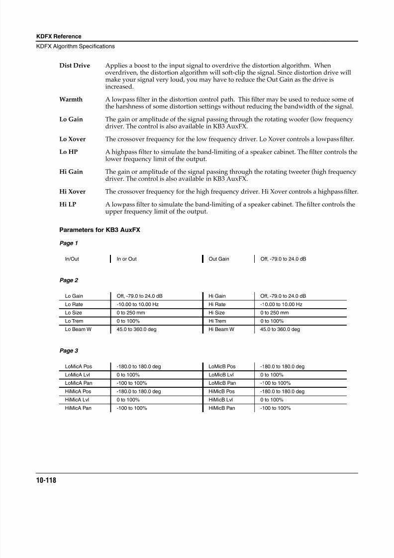
8/21/2019 MR_K2661
http://slidepdf.com/reader/full/mrk2661 200/499
10-118
KDFX Reference
KDFX Algorithm Specifications
Dist Drive Applies a boost to the input signal to overdrive the distortion algorithm. Whenoverdriven, the distortion algorithm will soft-clip the signal. Since distortion drive willmake your signal very loud, you may have to reduce the Out Gain as the drive isincreased.
Warmth A lowpass filter in the distortion control path. This filter may be used to reduce some ofthe harshness of some distortion settings without reducing the bandwidth of the signal.
Lo Gain The gain or amplitude of the signal passing through the rotating woofer (low frequencydriver. The control is also available in KB3 AuxFX.
Lo Xover The crossover frequency for the low frequency driver. Lo Xover controls a lowpass filter.
Lo HP A highpass filter to simulate the band-limiting of a speaker cabinet. The filter controls thelower frequency limit of the output.
Hi Gain The gain or amplitude of the signal passing through the rotating tweeter (high frequencydriver. The control is also available in KB3 AuxFX.
Hi Xover The crossover frequency for the high frequency driver. Hi Xover controls a highpass filter.
Hi LP A lowpass filter to simulate the band-limiting of a speaker cabinet. The filter controls theupper frequency limit of the output.
Parameters for KB3 AuxFX
Page 1
Page 2
Page 3
In/Out In or Out Out Gain Off, -79.0 to 24.0 dB
Lo Gain Off, -79.0 to 24.0 dB Hi Gain Off, -79.0 to 24.0 dB
Lo Rate -10.00 to 10.00 Hz Hi Rate -10.00 to 10.00 Hz
Lo Size 0 to 250 mm Hi Size 0 to 250 mm
Lo Trem 0 to 100% Hi Trem 0 to 100%
Lo Beam W 45.0 to 360.0 deg Hi Beam W 45.0 to 360.0 deg
LoMicA Pos -180.0 to 180.0 deg LoMicB Pos -180.0 to 180.0 deg
LoMicA Lvl 0 to 100% LoMicB Lvl 0 to 100%
LoMicA Pan -100 to 100% LoMicB Pan -100 to 100%
HiMicA Pos -180.0 to 180.0 deg HiMicB Pos -180.0 to 180.0 deg
HiMicA Lvl 0 to 100% HiMicB Lvl 0 to 100%
HiMicA Pan -100 to 100% HiMicB Pan -100 to 100%
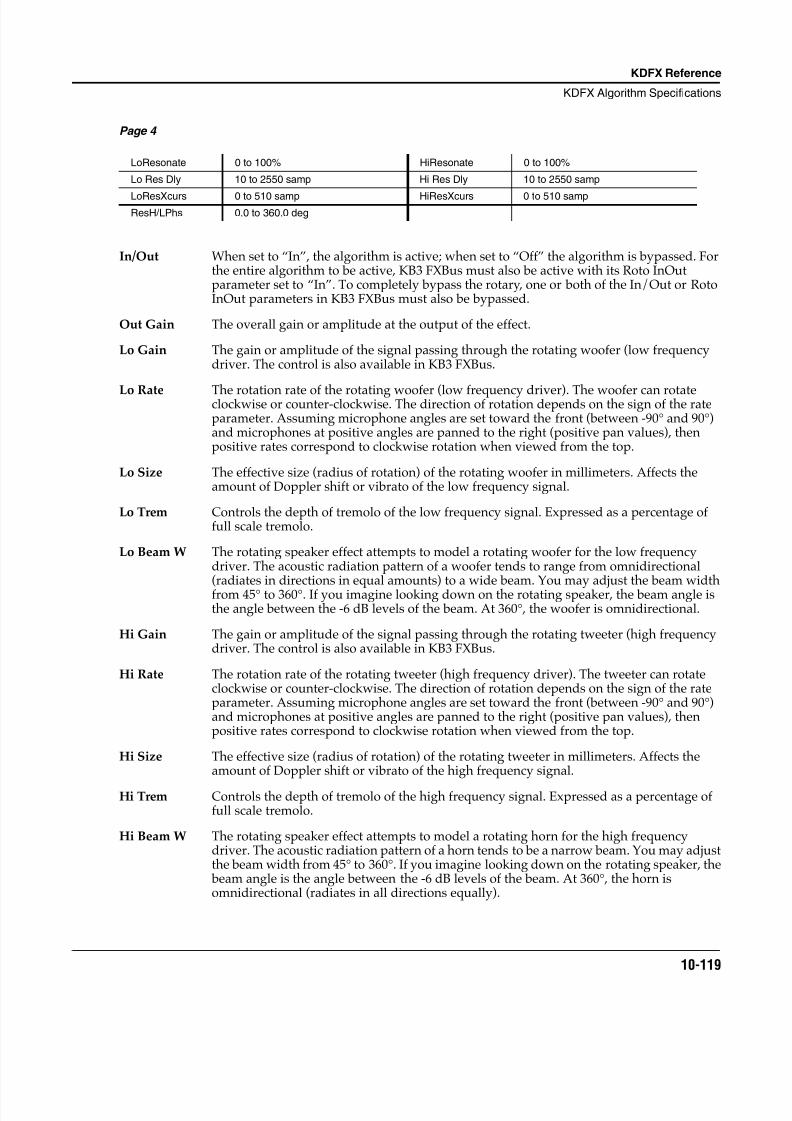
8/21/2019 MR_K2661
http://slidepdf.com/reader/full/mrk2661 201/499
KDFX Reference
KDFX Algorithm Specifications
10-119
Page 4
In/Out When set to “In”, the algorithm is active; when set to “Off” the algorithm is bypassed. Forthe entire algorithm to be active, KB3 FXBus must also be active with its Roto InOutparameter set to “In”. To completely bypass the rotary, one or both of the In/Out or RotoInOut parameters in KB3 FXBus must also be bypassed.
Out Gain The overall gain or amplitude at the output of the effect.
Lo Gain The gain or amplitude of the signal passing through the rotating woofer (low frequencydriver. The control is also available in KB3 FXBus.
Lo Rate The rotation rate of the rotating woofer (low frequency driver). The woofer can rotateclockwise or counter-clockwise. The direction of rotation depends on the sign of the rateparameter. Assuming microphone angles are set toward the front (between -90° and 90°)and microphones at positive angles are panned to the right (positive pan values), thenpositive rates correspond to clockwise rotation when viewed from the top.
Lo Size The effective size (radius of rotation) of the rotating woofer in millimeters. Affects theamount of Doppler shift or vibrato of the low frequency signal.
Lo Trem Controls the depth of tremolo of the low frequency signal. Expressed as a percentage offull scale tremolo.
Lo Beam W The rotating speaker effect attempts to model a rotating woofer for the low frequencydriver. The acoustic radiation pattern of a woofer tends to range from omnidirectional(radiates in directions in equal amounts) to a wide beam. You may adjust the beam widthfrom 45° to 360°. If you imagine looking down on the rotating speaker, the beam angle isthe angle between the -6 dB levels of the beam. At 360°, the woofer is omnidirectional.
Hi Gain The gain or amplitude of the signal passing through the rotating tweeter (high frequencydriver. The control is also available in KB3 FXBus.
Hi Rate The rotation rate of the rotating tweeter (high frequency driver). The tweeter can rotateclockwise or counter-clockwise. The direction of rotation depends on the sign of the rateparameter. Assuming microphone angles are set toward the front (between -90° and 90°)and microphones at positive angles are panned to the right (positive pan values), thenpositive rates correspond to clockwise rotation when viewed from the top.
Hi Size The effective size (radius of rotation) of the rotating tweeter in millimeters. Affects theamount of Doppler shift or vibrato of the high frequency signal.
Hi Trem Controls the depth of tremolo of the high frequency signal. Expressed as a percentage offull scale tremolo.
Hi Beam W The rotating speaker effect attempts to model a rotating horn for the high frequencydriver. The acoustic radiation pattern of a horn tends to be a narrow beam. You may adjustthe beam width from 45° to 360°. If you imagine looking down on the rotating speaker, the beam angle is the angle between the -6 dB levels of the beam. At 360°, the horn isomnidirectional (radiates in all directions equally).
LoResonate 0 to 100% HiResonate 0 to 100%
Lo Res Dly 10 to 2550 samp Hi Res Dly 10 to 2550 samp
LoResXcurs 0 to 510 samp HiResXcurs 0 to 510 sampResH/LPhs 0.0 to 360.0 deg
8/21/2019 MR_K2661
http://slidepdf.com/reader/full/mrk2661 202/499
10-120
KDFX Reference
KDFX Algorithm Specifications
Mic Pos The angle of the virtual microphones in degrees from the “front” of the rotating speaker.This parameter is not well suited to modulation because adjustments to it will result inlarge sample skips (audible as clicks when signal is passing through the effect). There arefour of these parameters to include 2 pairs (A and B) for high and low frequency drivers.
Mic Lvl The level of the virtual microphone signal being sent to the output. There are four of theseparameters to include 2 pairs (A and B) for high and low frequency drivers.
Mic Pan Left-right panning of the virtual microphone signals. A settings of -100% is panned fullyleft, and 100% is panned fully right. There are four of these parameters to include 2 pairs(A and B) for high and low frequency drivers.
LoResonate A simulation of cabinet resonant modes express as a percentage. For realism, you shoulduse very low settings. This is for the low frequency signal path.
Lo Res Dly The number of samples of delay in the resonator circuit in addition to the rotationexcursion delay. This is for the low frequency signal path.
LoResXcurs The number of samples of delay to sweep through the resonator at the rotation rate of the
rotating speaker. This is for the low frequency signal path.HiResonate A simulation of cabinet resonant modes express as a percentage. For realism, you should
use very low settings. This is for the high frequency signal path.
Hi Res Dly The number of samples of delay in the resonator circuit in addition to the rotationexcursion delay. This is for the high frequency signal path.
HiResXcurs The number of samples of delay to sweep through the resonator at the rotation rate of therotating speaker. This is for the high frequency signal path.
ResH/LPhs This parameter sets the relative phases of the high and low resonators. The angle value indegrees is somewhat arbitrary and you can expect the effect of this parameter to be rathersubtle.
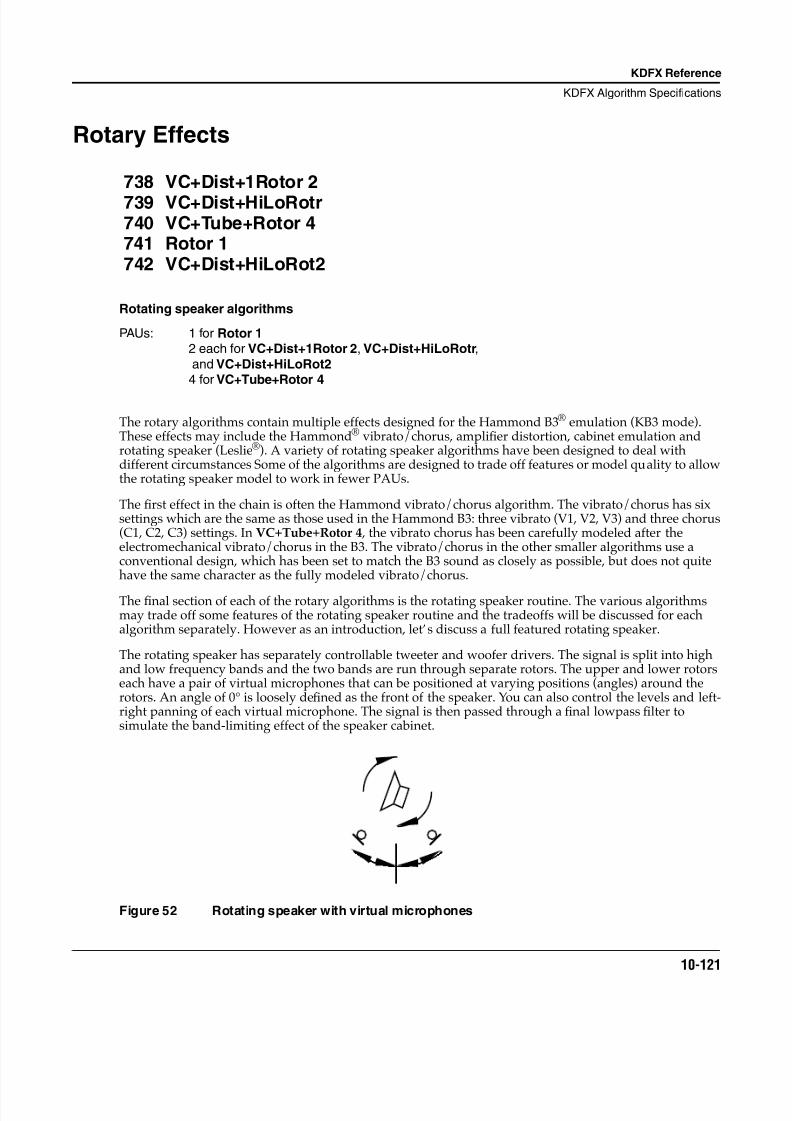
8/21/2019 MR_K2661
http://slidepdf.com/reader/full/mrk2661 203/499
KDFX Reference
KDFX Algorithm Specifications
10-121
Rotary Effects
738 VC+Dist+1Rotor 2
739 VC+Dist+HiLoRotr740 VC+Tube+Rotor 4741 Rotor 1742 VC+Dist+HiLoRot2
Rotating speaker algorithms
PAUs: 1 for Rotor 1 2 each for VC+Dist+1Rotor 2, VC+Dist+HiLoRotr,
and VC+Dist+HiLoRot2 4 for VC+Tube+Rotor 4
The rotary algorithms contain multiple effects designed for the Hammond B3® emulation (KB3 mode).These effects may include the Hammond® vibrato/chorus, amplifier distortion, cabinet emulation androtating speaker (Leslie®). A variety of rotating speaker algorithms have been designed to deal withdifferent circumstances Some of the algorithms are designed to trade off features or model quality to allowthe rotating speaker model to work in fewer PAUs.
The first effect in the chain is often the Hammond vibrato/chorus algorithm. The vibrato/chorus has sixsettings which are the same as those used in the Hammond B3: three vibrato (V1, V2, V3) and three chorus(C1, C2, C3) settings. In VC+Tube+Rotor 4 , the vibrato chorus has been carefully modeled after theelectromechanical vibrato/chorus in the B3. The vibrato/chorus in the other smaller algorithms use aconventional design, which has been set to match the B3 sound as closely as possible, but does not quitehave the same character as the fully modeled vibrato/chorus.
The final section of each of the rotary algorithms is the rotating speaker routine. The various algorithmsmay trade off some features of the rotating speaker routine and the tradeoffs will be discussed for eachalgorithm separately. However as an introduction, let’s discuss a full featured rotating speaker.
The rotating speaker has separately controllable tweeter and woofer drivers. The signal is split into highand low frequency bands and the two bands are run through separate rotors. The upper and lower rotorseach have a pair of virtual microphones that can be positioned at varying positions (angles) around therotors. An angle of 0° is loosely defined as the front of the speaker. You can also control the levels and left-right panning of each virtual microphone. The signal is then passed through a final lowpass filter tosimulate the band-limiting effect of the speaker cabinet.
Figure 52 Rotating speaker with virtual microphones
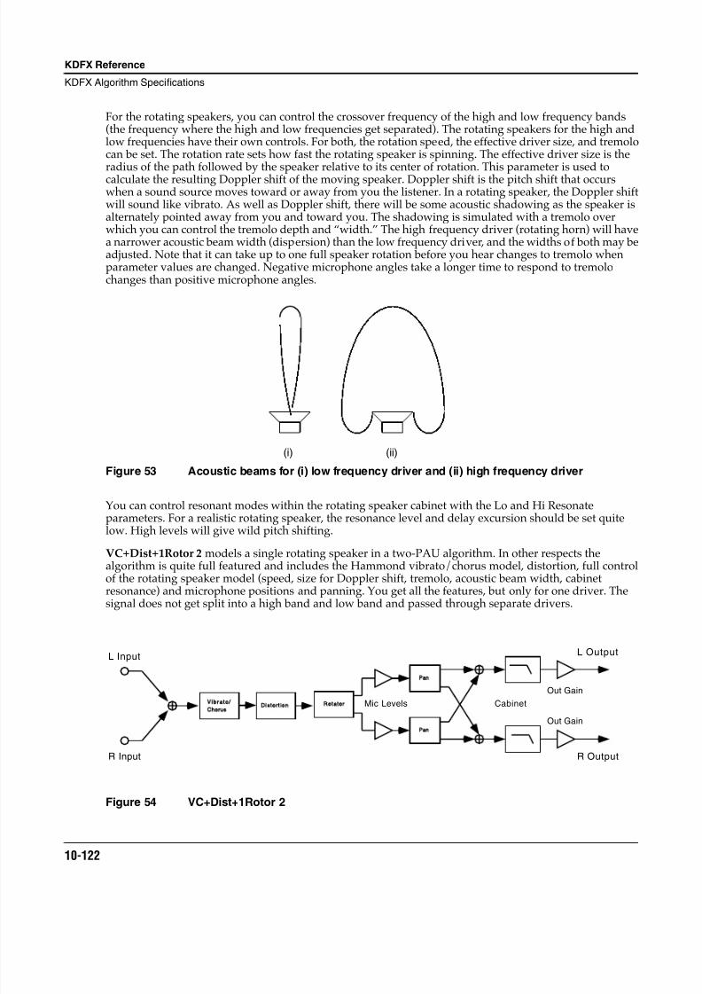
8/21/2019 MR_K2661
http://slidepdf.com/reader/full/mrk2661 204/499
10-122
KDFX Reference
KDFX Algorithm Specifications
For the rotating speakers, you can control the crossover frequency of the high and low frequency bands(the frequency where the high and low frequencies get separated). The rotating speakers for the high andlow frequencies have their own controls. For both, the rotation speed, the effective driver size, and tremolocan be set. The rotation rate sets how fast the rotating speaker is spinning. The effective driver size is theradius of the path followed by the speaker relative to its center of rotation. This parameter is used tocalculate the resulting Doppler shift of the moving speaker. Doppler shift is the pitch shift that occurswhen a sound source moves toward or away from you the listener. In a rotating speaker, the Doppler shiftwill sound like vibrato. As well as Doppler shift, there will be some acoustic shadowing as the speaker isalternately pointed away from you and toward you. The shadowing is simulated with a tremolo overwhich you can control the tremolo depth and “width.” The high frequency driver (rotating horn) will havea narrower acoustic beam width (dispersion) than the low frequency driver, and the widths of both may beadjusted. Note that it can take up to one full speaker rotation before you hear changes to tremolo whenparameter values are changed. Negative microphone angles take a longer time to respond to tremolochanges than positive microphone angles.
Figure 53 Acoustic beams for (i) low frequency driver and (ii) high frequency driver
You can control resonant modes within the rotating speaker cabinet with the Lo and Hi Resonate
parameters. For a realistic rotating speaker, the resonance level and delay excursion should be set quitelow. High levels will give wild pitch shifting.
VC+Dist+1Rotor 2 models a single rotating speaker in a two-PAU algorithm. In other respects thealgorithm is quite full featured and includes the Hammond vibrato/chorus model, distortion, full controlof the rotating speaker model (speed, size for Doppler shift, tremolo, acoustic beam width, cabinetresonance) and microphone positions and panning. You get all the features, but only for one driver. Thesignal does not get split into a high band and low band and passed through separate drivers.
Figure 54 VC+Dist+1Rotor 2
(i) (ii)
Vibrato
ChorusDistortion
Pan
Pan
Rotator Cabinet
Out Gain
Out Gain
L Input
R Input
L Output
R Output
Mic Levels
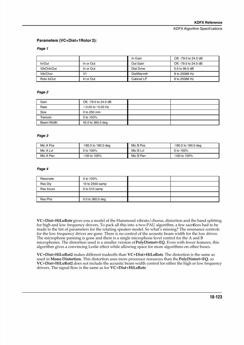
8/21/2019 MR_K2661
http://slidepdf.com/reader/full/mrk2661 205/499
KDFX Reference
KDFX Algorithm Specifications
10-123
Parameters (VC+Dist+1Rotor 2):
Page 1
Page 2
Page 3
Page 4
VC+Dist+HiLoRotr gives you a model of the Hammond vibrato/chorus, distortion and the band splittingfor high and low frequency drivers. To pack all this into a two-PAU algorithm, a few sacrifices had to bemade to the list of parameters for the rotating speaker model. So what’s missing? The resonance controlsfor the low frequency driver are gone. There is no control of the acoustic beam width for the low driver.The microphone panning is gone and there is a single microphone level control for the A and B
microphones. The distortion used is a smaller version of PolyDistort+EQ. Even with fewer features, thisalgorithm gives a convincing Leslie effect while allowing space for more algorithms on other buses.
VC+Dist+HiLoRot2 makes different tradeoffs than VC+Dist+HiLoRotr. The distortion is the same asused in Mono Distortion. This distortion uses more processor resources than the PolyDistort+EQ , soVC+Dist+HiLoRot2 does not include the acoustic beam width control for either the high or low frequencydrivers. The signal flow is the same as for VC+Dist+HiLoRotr.
In Gain Off, -79.0 to 24.0 dB
In/Out In or Out Out Gain Off, -79.0 to 24.0 dB
VibChInOut In or Out Dist Drive 0.0 to 96.0 dB
Vib/Chor V1 DistWarmth 8 to 25088 Hz
Roto InOut In or Out Cabinet LP 8 to 25088 Hz
Gain Off, -79.0 to 24.0 dB
Rate -10.00 to 10.00 Hz
Size 0 to 250 mm
Tremolo 0 to 100%
Beam Width 45.0 to 360.0 deg
Mic A Pos -180.0 to 180.0 deg Mic B Pos -180.0 to 180.0 deg
Mic A Lvl 0 to 100% Mic B Lvl 0 to 100%
Mic A Pan -100 to 100% Mic B Pan -100 to 100%
Resonate 0 to 100%
Res Dly 10 to 2550 samp
Res Xcurs 0 to 510 samp
Res Phs 0.0 to 360.0 deg
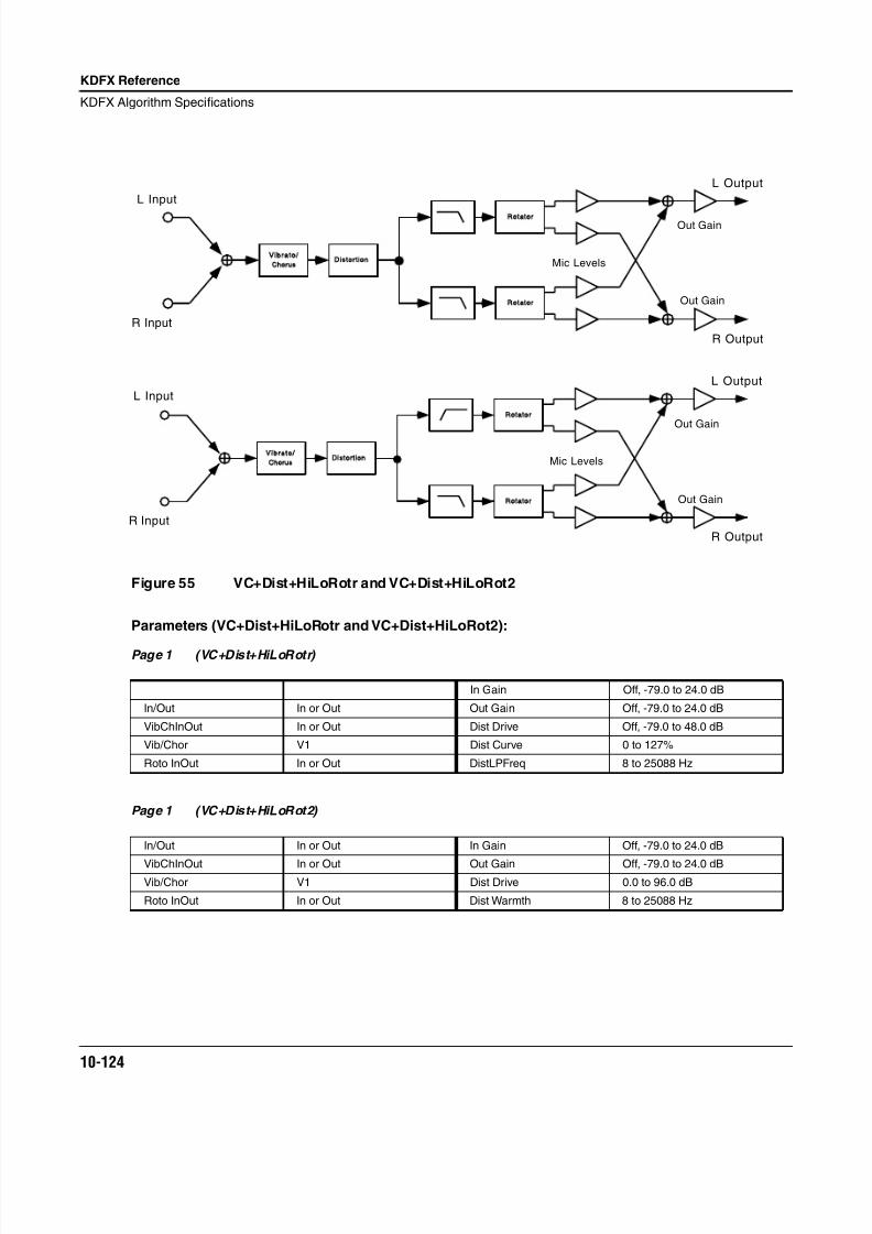
8/21/2019 MR_K2661
http://slidepdf.com/reader/full/mrk2661 206/499
10-124
KDFX Reference
KDFX Algorithm Specifications
Figure 55 VC+Dist+HiLoRotr and VC+Dist+HiLoRot2
Parameters (VC+Dist+HiLoRotr and VC+Dist+HiLoRot2):
Page 1 (VC+Dist+HiLoRotr)
Page 1 (VC+Dist+HiLoRot2)
In Gain Off, -79.0 to 24.0 dB
In/Out In or Out Out Gain Off, -79.0 to 24.0 dB
VibChInOut In or Out Dist Drive Off, -79.0 to 48.0 dB
Vib/Chor V1 Dist Curve 0 to 127%
Roto InOut In or Out DistLPFreq 8 to 25088 Hz
In/Out In or Out In Gain Off, -79.0 to 24.0 dB
VibChInOut In or Out Out Gain Off, -79.0 to 24.0 dBVib/Chor V1 Dist Drive 0.0 to 96.0 dB
Roto InOut In or Out Dist Warmth 8 to 25088 Hz
Vibrato
ChorusDistortion
Rotator
Rotator
Mic Levels
Out Gain
Out Gain
L Input
R Input
L Output
R Output
Vibrato
ChorusDistortion
Rotator
Rotator
Mic Levels
Out Gain
Out Gain
L Input
R Input
L Output
R Output
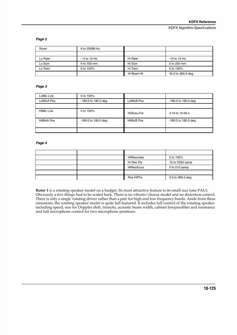
8/21/2019 MR_K2661
http://slidepdf.com/reader/full/mrk2661 207/499
KDFX Reference
KDFX Algorithm Specifications
10-125
Page 2
Page 3
Page 4
Rotor 1 is a rotating speaker model on a budget. Its most attractive feature is its small size (one PAU).Obviously a few things had to be scaled back. There is no vibrato/chorus model and no distortion control.There is only a single rotating driver rather than a pair for high and low frequency bands. Aside from theseomissions, the rotating speaker model is quite full featured. It includes full control of the rotating speakerincluding speed, size for Doppler shift, tremolo, acoustic beam width, cabinet lowpass filter and resonanceand full microphone control for two microphone positions.
Xover 8 to 25088 Hz
Lo Rate -10 to 10 Hz Hi Rate -10 to 10 HzLo Size 0 to 250 mm Hi Size 0 to 250 mm
Lo Trem 0 to 100% Hi Trem 0 to 100%
Hi Beam W 45.0 to 360.0 deg
LoMic Lvls 0 to 100%
LoMicA Pos -180.0 to 180.0 deg LoMicB Pos -180.0 to 180.0 deg
HiMic Lvls 0 to 100%HiSlow>Fst 0.10 to 10.00 s
HiMicA Pos -180.0 to 180.0 deg HiMicB Pos -180.0 to 180.0 deg
HiResonate 0 to 100%
Hi Res Dly 10 to 2550 samp
HiResXcurs 0 to 510 samp
Res HiPhs 0.0 to 360.0 deg
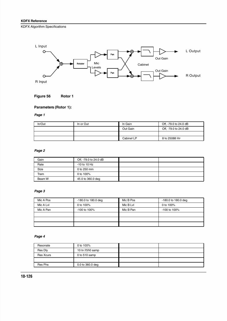
8/21/2019 MR_K2661
http://slidepdf.com/reader/full/mrk2661 208/499
10-126
KDFX Reference
KDFX Algorithm Specifications
Figure 56 Rotor 1
Parameters (Rotor 1):
Page 1
Page 2
Page 3
Page 4
In/Out In or Out In Gain Off, -79.0 to 24.0 dB
Out Gain Off, -79.0 to 24.0 dB
Cabinet LP 8 to 25088 Hz
Gain Off, -79.0 to 24.0 dB
Rate -10 to 10 Hz
Size 0 to 250 mm
Trem 0 to 100%
Beam W 45.0 to 360.0 deg
Mic A Pos -180.0 to 180.0 deg Mic B Pos -180.0 to 180.0 deg
Mic A Lvl 0 to 100% Mic B Lvl 0 to 100%
Mic A Pan -100 to 100% Mic B Pan -100 to 100%
Resonate 0 to 100%
Res Dly 10 to 2550 samp
Res Xcurs 0 to 510 samp
Res Phs 0.0 to 360.0 deg
Pan
Pan
Rotator Mic
LevelsCabinet
Out Gain
Out Gain
L Input
R Input
L Output
R Output
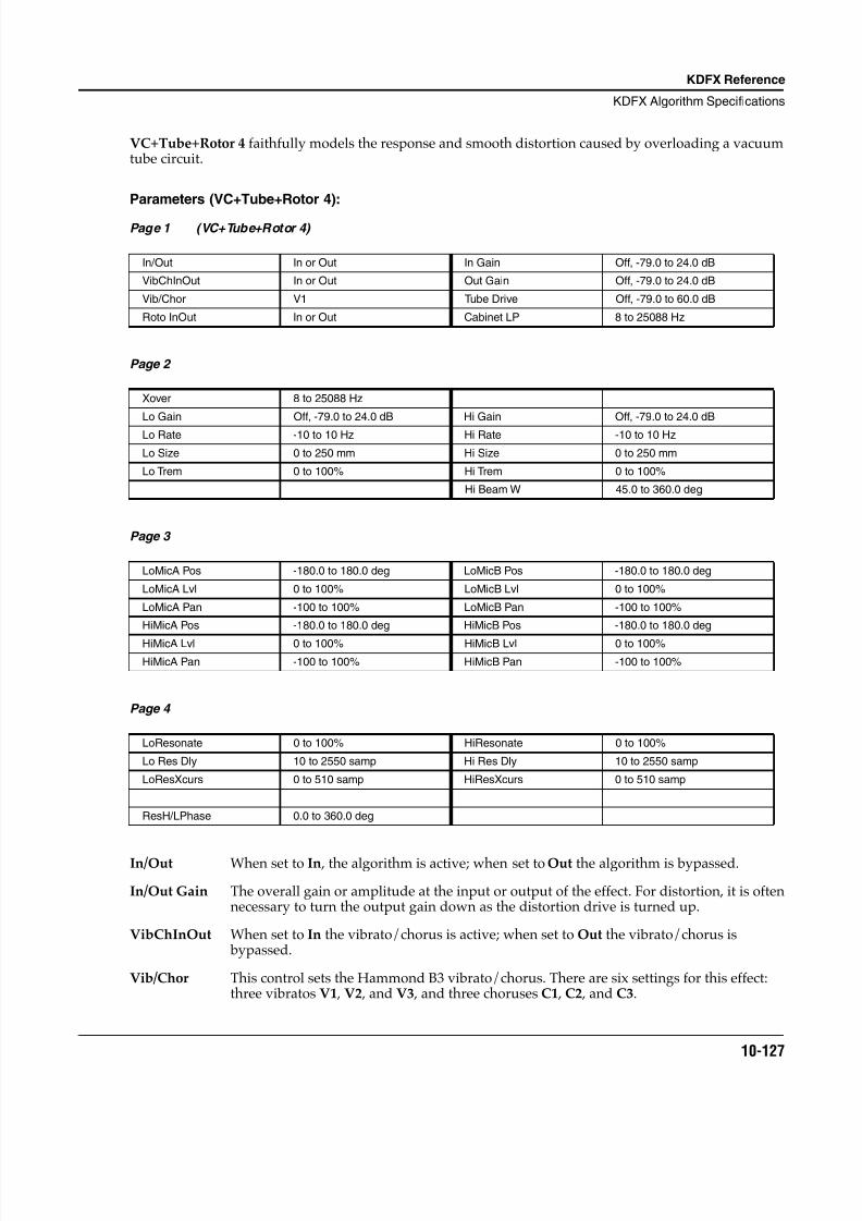
8/21/2019 MR_K2661
http://slidepdf.com/reader/full/mrk2661 209/499
KDFX Reference
KDFX Algorithm Specifications
10-127
VC+Tube+Rotor 4 faithfully models the response and smooth distortion caused by overloading a vacuumtube circuit.
Parameters (VC+Tube+Rotor 4):
Page 1 (VC+Tube+Rotor 4)
Page 2
Page 3
Page 4
In/Out When set to In , the algorithm is active; when set to Out the algorithm is bypassed.
In/Out Gain The overall gain or amplitude at the input or output of the effect. For distortion, it is oftennecessary to turn the output gain down as the distortion drive is turned up.
VibChInOut When set to In the vibrato/chorus is active; when set to Out the vibrato/chorus is bypassed.
Vib/Chor This control sets the Hammond B3 vibrato/chorus. There are six settings for this effect:three vibratos V1 , V2 , and V3 , and three choruses C1 , C2 , and C3.
In/Out In or Out In Gain Off, -79.0 to 24.0 dB
VibChInOut In or Out Out Gain Off, -79.0 to 24.0 dB
Vib/Chor V1 Tube Drive Off, -79.0 to 60.0 dB
Roto InOut In or Out Cabinet LP 8 to 25088 Hz
Xover 8 to 25088 Hz
Lo Gain Off, -79.0 to 24.0 dB Hi Gain Off, -79.0 to 24.0 dB
Lo Rate -10 to 10 Hz Hi Rate -10 to 10 Hz
Lo Size 0 to 250 mm Hi Size 0 to 250 mm
Lo Trem 0 to 100% Hi Trem 0 to 100%
Hi Beam W 45.0 to 360.0 deg
LoMicA Pos -180.0 to 180.0 deg LoMicB Pos -180.0 to 180.0 deg
LoMicA Lvl 0 to 100% LoMicB Lvl 0 to 100%
LoMicA Pan -100 to 100% LoMicB Pan -100 to 100%
HiMicA Pos -180.0 to 180.0 deg HiMicB Pos -180.0 to 180.0 deg
HiMicA Lvl 0 to 100% HiMicB Lvl 0 to 100%
HiMicA Pan -100 to 100% HiMicB Pan -100 to 100%
LoResonate 0 to 100% HiResonate 0 to 100%
Lo Res Dly 10 to 2550 samp Hi Res Dly 10 to 2550 samp
LoResXcurs 0 to 510 samp HiResXcurs 0 to 510 samp
ResH/LPhase 0.0 to 360.0 deg
8/21/2019 MR_K2661
http://slidepdf.com/reader/full/mrk2661 210/499
10-128
KDFX Reference
KDFX Algorithm Specifications
Roto InOut When set to In the rotary speaker is active; when set to Out the rotary speaker is bypassed.
Dist Curve Controls the curvature of the distortion. 0% is no curvature (no distortion at all). At 100% ,the curve bends over smoothly and becomes perfectly flat right before it goes intoclipping.
DistWarmth A lowpass filter in the distortion control path. This filter may be used to reduce some ofthe harshness of some distortion settings without reducing the bandwidth of the signal.
DistLPFreq Controls one-pole lowpass filters in the PolyDistort+EQ (in VC+Dist+HiLoRotr).Without the lowpass filters, the sound tends to be too bright and raspy. With lessdistortion drive, less filtering is needed. If you turn off the distortion curve (set to 0%),you should turn off the lowpass filter by setting it to the highest frequency.
Cabinet LP A lowpass filter to simulate the band-limiting of a speaker cabinet. The filter controls theupper frequency limit of the output.
Xover The frequency at which high and low frequency bands are split and sent to separaterotating drivers.
Gain The gain or amplitude of the signal passing through the rotating speaker.
Rate The speed of the speaker rotation.
Size The effective size (radius of rotation) of the rotating speaker in millimeters. Affects theamount of Doppler shift or vibrato of signal.
Tremolo Controls the depth of tremolo of the signal. Expressed as a percentage of full scale
tremolo.
Beam Width The rotating speaker effect models the acoustic radiation pattern of a speaker rangingfrom omnidirectional (radiates in directions in equal amounts) to a wide beam. You mayadjust the beam width from 45° to 360°. If you imagine looking down on the rotatingspeaker, the beam angle is the angle between the -6 dB levels of the beam. At 360° , thespeaker is omnidirectional.
Resonate A simulation of cabinet resonant modes expressed as a percentage. For realism, youshould use very low settings.
Res Dly The number of samples of delay in the resonator circuit in addition to the rotationexcursion delay.
Res XcursThe number of samples of delay to sweep through the resonator at the rotation rate of therotating speaker.
Res Phs This parameter sets the relative phases the resonators. The angle value in degrees issomewhat arbitrary and you can expect the effect of this parameter to be rather subtle.
Lo Gain The gain or amplitude of the signal passing through the rotating woofer (low frequency)driver.
Lo Rate The speed of the woofer rotation.
Dist Drive orTube Drive
Applies a boost to the input signal to overdrive the distortion algorithm. Whenoverdriven, the distortion algorithm will soft-clip the signal. Since distortion drive willmake your signal very loud, you may have to reduce the Out Gain as the drive isincreased.
8/21/2019 MR_K2661
http://slidepdf.com/reader/full/mrk2661 211/499
KDFX Reference
KDFX Algorithm Specifications
10-129
Lo Size The effective size (radius of rotation) of the rotating woofer in millimeters. Affects theamount of Doppler shift or vibrato of the low frequency signal.
Lo Trem Controls the depth of tremolo of the low frequency signal. Expressed as a percentage offull scale tremolo.
Hi Gain The gain or amplitude of the signal passing through the rotating tweeter (high frequency)driver.
Hi Rate The speed of the tweeter rotation.
Hi Size The effective size (radius of rotation) of the rotating tweeter in millimeters. Affects theamount of Doppler shift or vibrato of the high frequency signal.
Hi Trem Controls the depth of tremolo of the high frequency signal. Expressed as a percentage offull scale tremolo.
Hi Beam W The rotating speaker effect models a rotating horn for the high frequency driver. Theacoustic radiation pattern of a horn tends to be a narrow beam. You may adjust the beamwidth from 45° to 360°. If you imagine looking down on the rotating speaker, the beamangle is the angle between the -6 dB levels of the beam. At 360° , the horn isomnidirectional (radiates in all directions equally).
Mic Pos The angle of the virtual microphones in degrees from the “front” of the rotating speaker.This parameter is not well suited to modulation because adjustments to it result in largesample skips (audible as clicks when signal is passing through the effect). There are twopairs of microphones (A and B) for high and low frequency drivers.
Mic Lvl The level of the virtual microphone signal being sent to the output. There are two pairs ofmicrophones (A and B) for high and low frequency drivers.
Mic Pan Left-right panning of the virtual microphone signals. A setting of -100% is panned fullyleft, and 100% is panned fully right. There are four of these parameters to include twopairs (A and B) for high and low frequency drivers.
LoResonate A simulation of cabinet resonant modes expressed as a percentage. For realism, youshould use very low settings. This is for the low frequency signal path.
Lo Res Dly The number of samples of delay in the resonator circuit in addition to the rotationexcursion delay. This is for the low frequency signal path.
LoResXcurs The number of samples of delay to sweep through the resonator at the rotation rate of therotating speaker. This is for the low frequency signal path.
HiResonate A simulation of cabinet resonant modes expressed as a percentage. For realism, youshould use very low settings. This is for the high frequency signal path.
Hi Res Dly The number of samples of delay in the resonator circuit in addition to the rotationexcursion delay. This is for the high frequency signal path.
HiResXcurs The number of samples of delay to sweep through the resonator at the rotation rate of therotating speaker. This is for the high frequency signal path.
ResH/LPhs This parameter sets the relative phases of the high and low resonators. The angle value indegrees is somewhat arbitrary and you can expect the effect of this parameter to be rathersubtle.
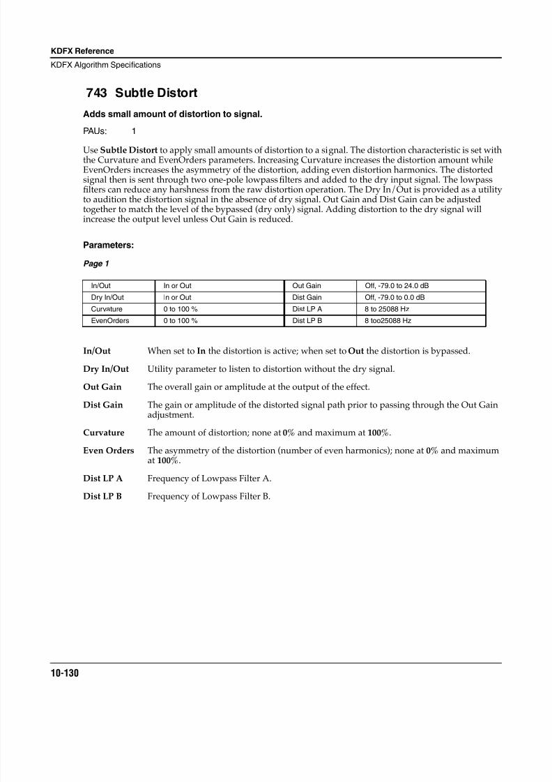
8/21/2019 MR_K2661
http://slidepdf.com/reader/full/mrk2661 212/499
10-130
KDFX Reference
KDFX Algorithm Specifications
743 Subtle Distort
Adds small amount of distortion to signal.
PAUs: 1
Use Subtle Distort to apply small amounts of distortion to a signal. The distortion characteristic is set withthe Curvature and EvenOrders parameters. Increasing Curvature increases the distortion amount whileEvenOrders increases the asymmetry of the distortion, adding even distortion harmonics. The distortedsignal then is sent through two one-pole lowpass filters and added to the dry input signal. The lowpassfilters can reduce any harshness from the raw distortion operation. The Dry In/Out is provided as a utilityto audition the distortion signal in the absence of dry signal. Out Gain and Dist Gain can be adjustedtogether to match the level of the bypassed (dry only) signal. Adding distortion to the dry signal willincrease the output level unless Out Gain is reduced.
Parameters:
Page 1
In/Out When set to In the distortion is active; when set to Out the distortion is bypassed.
Dry In/Out Utility parameter to listen to distortion without the dry signal.
Out Gain The overall gain or amplitude at the output of the effect.
Dist Gain The gain or amplitude of the distorted signal path prior to passing through the Out Gainadjustment.
Curvature The amount of distortion; none at 0% and maximum at 100%.
Even Orders The asymmetry of the distortion (number of even harmonics); none at 0% and maximumat 100%.
Dist LP A Frequency of Lowpass Filter A.
Dist LP B Frequency of Lowpass Filter B.
In/Out In or Out Out Gain Off, -79.0 to 24.0 dB
Dry In/Out In or Out Dist Gain Off, -79.0 to 0.0 dB
Curvature 0 to 100 % Dist LP A 8 to 25088 Hz
EvenOrders 0 to 100 % Dist LP B 8 too25088 Hz
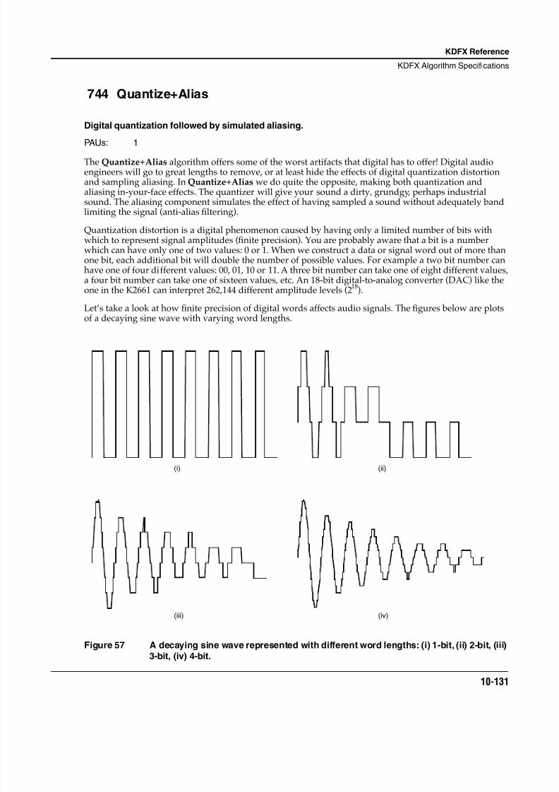
8/21/2019 MR_K2661
http://slidepdf.com/reader/full/mrk2661 213/499
KDFX Reference
KDFX Algorithm Specifications
10-131
744 Quantize+Alias
Digital quantization followed by simulated aliasing.
PAUs: 1
The Quantize+Alias algorithm offers some of the worst artifacts that digital has to offer! Digital audioengineers will go to great lengths to remove, or at least hide the effects of digital quantization distortionand sampling aliasing. In Quantize+Alias we do quite the opposite, making both quantization andaliasing in-your-face effects. The quantizer will give your sound a dirty, grundgy, perhaps industrialsound. The aliasing component simulates the effect of having sampled a sound without adequately bandlimiting the signal (anti-alias filtering).
Quantization distortion is a digital phenomenon caused by having only a limited number of bits withwhich to represent signal amplitudes (finite precision). You are probably aware that a bit is a numberwhich can have only one of two values: 0 or 1. When we construct a data or signal word out of more thanone bit, each additional bit will double the number of possible values. For example a two bit number canhave one of four different values: 00, 01, 10 or 11. A three bit number can take one of eight different values,a four bit number can take one of sixteen values, etc. An 18-bit digital-to-analog converter (DAC) like theone in the K2661 can interpret 262,144 different amplitude levels (218).
Let’s take a look at how finite precision of digital words affects audio signals. The figures below are plotsof a decaying sine wave with varying word lengths.
Figure 57 A decaying sine wave represented with different word lengths: (i) 1-bit, (ii) 2-bit, (iii)
3-bit, (iv) 4-bit.
(i) (ii)
(iii) (iv)
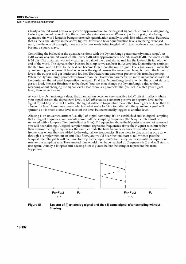
8/21/2019 MR_K2661
http://slidepdf.com/reader/full/mrk2661 214/499
10-132
KDFX Reference
KDFX Algorithm Specifications
Clearly a one-bit word gives a very crude approximation to the original signal while four bits is beginningto do a good job of reproducing the original decaying sine wave. When a good strong signal is beingquantized (its word length is being shortened), quantization usually sounds like additive noise. But noticethat as the signal decays in the above figures, fewer and fewer quantization levels are being exerciseduntil, like the one bit example, there are only two levels being toggled. With just two levels, your signal has become a square wave.
Controlling the bit level of the quantizer is done with the DynamRange parameter (dynamic range). At0 dB we are at a one-bit word length. Every 6 dB adds approximately one bit, so at 144 dB , the word lengthis 24 bits. The quantizer works by cutting the gain of the input signal, making the lowest bits fall off theend of the word. The signal is then boosted back up so we can hear it. At very low DynamRange settings,the step from one bit level to the next can become larger than the input signal. The signal can still make thequantizer toggle between bit level whenever the signal crosses the zero signal level, but with the larger bitlevels, the output will get louder and louder. The Headroom parameter prevents this from happening.When the DynamRange parameter is lower than the Headroom parameter, no more signal boost is addedto counter-act the cut used to quantize the signal. Find the DynamRange level at which the output starts toget too loud, then set Headroom to that level. You can then change the DynamRange value withoutworrying about changing the signal level. Headroom is a parameter that you set to match your signallevel, then leave it alone.
At very low DynamRange values, the quantization becomes very sensitive to DC offset. It affects whereyour signal crosses the digital zero level. A DC offset adds a constant positive or negative level to thesignal. By adding positive DC offset, the signal will tend to quantize more often to a higher bit level than toa lower bit level. In extreme cases (which is what we’re looking for, after all), the quantized signal willsputter, as it is stuck at one level most of the time, but occasionally toggles to another level.
Aliasing is an unwanted artifact (usually!) of digital sampling. It’s an established rule in digital samplingthat all signal frequency components above half the sampling frequency (the Nyquist rate) must beremoved with a lowpass filter (anti-aliasing filter). If frequencies above the Nyquist rate are not removed,you will hear aliasing. A digital sampler cannot represent frequencies above the Nyquist rate, but ratherthan remove the high frequencies, the sampler folds the high frequencies back down into the lowerfrequencies where they are added to the original low frequencies. If you were to play a rising pure tonethrough a sampler without an anti-alias filter, you would hear the tone start to fall when it past the
Nyquist rate. The pitch will continue to drop as the input tone’s frequency increases until the input tonereaches the sampling rate. The sampled tone would then have reached dc (frequency is 0) and will start torise again. Usually a lowpass anti-aliasing filter is placed before the sampler to prevent this fromhappening.
Figure 58 Spectra of (i) an analog signal and the (ii) same signal after sampling withoutfiltering
FsFn=Fs/2
(i)
FsFn=Fs/2
(ii)
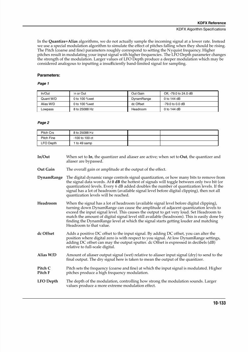
8/21/2019 MR_K2661
http://slidepdf.com/reader/full/mrk2661 215/499
KDFX Reference
KDFX Algorithm Specifications
10-133
In the Quantize+Alias algorithms, we do not actually sample the incoming signal at a lower rate. Insteadwe use a special modulation algorithm to simulate the effect of pitches falling when they should be rising.The Pitch (coarse and fine) parameters roughly correspond to setting the Nyquist frequency. Higherpitches result in modulating your input signal with higher frequencies. The LFO Depth parameter changesthe strength of the modulation. Larger values of LFO Depth produce a deeper modulation which may beconsidered analogous to inputting a insuf ficiently band-limited signal for sampling.
Parameters:
Page 1
Page 2
In/Out When set to In , the quantizer and aliaser are active; when set to Out , the quantizer andaliaser are bypassed.
Out Gain The overall gain or amplitude at the output of the effect.
DynamRange The digital dynamic range controls signal quantization, or how many bits to remove fromthe signal data words. At 0 dB the hottest of signals will toggle between only two bit (orquantization) levels. Every 6 dB added doubles the number of quantization levels. If thesignal has a lot of headroom (available signal level before digital clipping), then not allquantization levels will be reached.
Headroom When the signal has a lot of headroom (available signal level before digital clipping),turning down DynamRange can cause the amplitude of adjacent quantization levels toexceed the input signal level. This causes the output to get very loud. Set Headroom tomatch the amount of digital signal level still available (headroom). This is easily done byfinding the DynamRange level at which the signal starts getting louder and matchingHeadroom to that value.
dc Offset Adds a positive DC offset to the input signal. By adding DC offset, you can alter theposition where digital zero is with respect to you signal. At low DynamRange settings,adding DC offset can may the output sputter. dc Offset is expressed in decibels (dB)
relative to full-scale digital.
Alias W/D Amount of aliaser output signal (wet) relative to aliaser input signal (dry) to send to thefinal output. The dry signal here is taken to mean the output of the quantizer.
LFO Depth The depth of the modulation, controlling how strong the modulation sounds. Largervalues produce a more extreme modulation effect.
In/Out In or Out Out Gain Off, -79.0 to 24.0 dB
Quant W/D 0 to 100 %wet DynamRange 0 to 144 dB
Alias W/D 0 to 100 %wet dc Offset -79.0 to 0.0 dB
Lowpass 8 to 25088 Hz Headroom 0 to 144 dB
Pitch Crs 8 to 25088 Hz
Pitch Fine -100 to 100 ct
LFO Depth 1 to 49 samp
Pitch CPitch F
Pitch sets the frequency (coarse and fine) at which the input signal is modulated. Higherpitches produce a high frequency modulation.
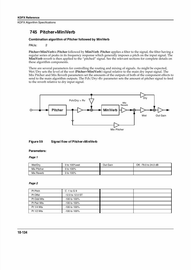
8/21/2019 MR_K2661
http://slidepdf.com/reader/full/mrk2661 216/499
10-134
KDFX Reference
KDFX Algorithm Specifications
745 Pitcher+MiniVerb
Combination algorithm of Pitcher followed by MiniVerb
PAUs: 2
Pitcher+MiniVerbis Pitcher followed by MiniVerb. Pitcher applies a filter to the signal, the filter having aregular series of peaks in its frequency response which generally imposes a pitch on the input signal. TheMiniVerb reverb is then applied to the “pitched” signal. See the relevant sections for complete details onthese algorithm components.
There are several parameters for controlling the routing and mixing of signals. As might be expected,Wet/Dry sets the level of the wet (Pitcher+MiniVerb) signal relative to the main dry input signal. TheMix Pitcher and Mix Reverb parameters set the amounts of the outputs of both of the component effects tosend to the main algorithm outputs. The Pch/Dry>Rv parameter sets the amount of pitcher signal to feedto the reverb relative to dry input signal.
Figure 59 Signal flow of Pitcher+MiniVerb
Parameters:
Page 1
Page 2
Wet/Dry 0 to 100%wet Out Gain Off, -79.0 to 24.0 dB
Mix Pitcher 0 to 100%
Mix Reverb 0 to 100%
Pt Pitch C -1 to G 9
Pt Offst -12.0 to 12.0 ST
Pt Odd Wts -100 to 100%
Pt Pair Wts -100 to 100%
Pt 1/4 Wts -100 to 100%
Pt 1/2 Wts -100 to 100%
Mix Pitcher
Pitcher MiniVerb
Pch/Dry > RvMix
Reverb
Wet Out Gain
Dry
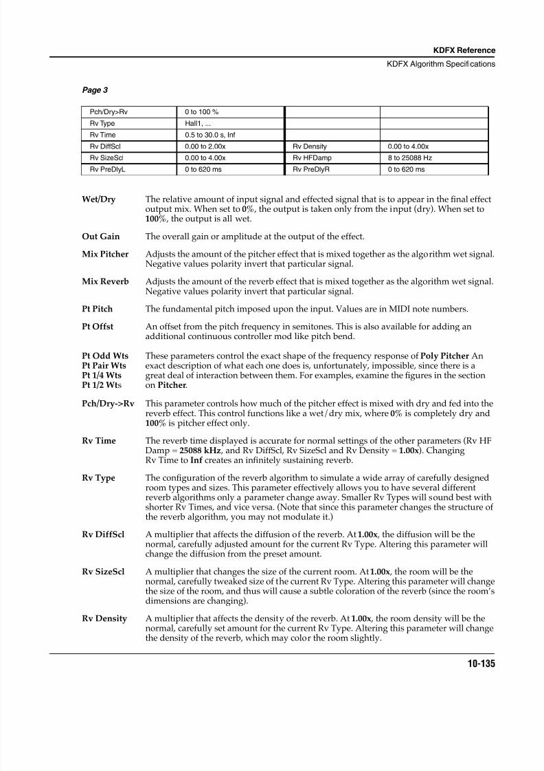
8/21/2019 MR_K2661
http://slidepdf.com/reader/full/mrk2661 217/499
KDFX Reference
KDFX Algorithm Specifications
10-135
Page 3
Wet/Dry The relative amount of input signal and effected signal that is to appear in the final effectoutput mix. When set to 0% , the output is taken only from the input (dry). When set to100% , the output is all wet.
Out Gain The overall gain or amplitude at the output of the effect.
Mix Pitcher Adjusts the amount of the pitcher effect that is mixed together as the algorithm wet signal.Negative values polarity invert that particular signal.
Mix Reverb Adjusts the amount of the reverb effect that is mixed together as the algorithm wet signal.Negative values polarity invert that particular signal.
Pt Pitch The fundamental pitch imposed upon the input. Values are in MIDI note numbers.
Pt Offst An offset from the pitch frequency in semitones. This is also available for adding anadditional continuous controller mod like pitch bend.
Pch/Dry->Rv This parameter controls how much of the pitcher effect is mixed with dry and fed into thereverb effect. This control functions like a wet/dry mix, where 0% is completely dry and100% is pitcher effect only.
Rv Time The reverb time displayed is accurate for normal settings of the other parameters (Rv HFDamp = 25088 kHz , and Rv DiffScl, Rv SizeScl and Rv Density = 1.00x). ChangingRv Time to Inf creates an infinitely sustaining reverb.
Rv Type The configuration of the reverb algorithm to simulate a wide array of carefully designedroom types and sizes. This parameter effectively allows you to have several differentreverb algorithms only a parameter change away. Smaller Rv Types will sound best withshorter Rv Times, and vice versa. (Note that since this parameter changes the structure ofthe reverb algorithm, you may not modulate it.)
Rv DiffScl A multiplier that affects the diffusion of the reverb. At 1.00x , the diffusion will be thenormal, carefully adjusted amount for the current Rv Type. Altering this parameter willchange the diffusion from the preset amount.
Rv SizeScl A multiplier that changes the size of the current room. At 1.00x , the room will be thenormal, carefully tweaked size of the current Rv Type. Altering this parameter will changethe size of the room, and thus will cause a subtle coloration of the reverb (since the room’sdimensions are changing).
Rv Density A multiplier that affects the density of the reverb. At 1.00x , the room density will be thenormal, carefully set amount for the current Rv Type. Altering this parameter will changethe density of the reverb, which may color the room slightly.
Pch/Dry>Rv 0 to 100 %
Rv Type Hall1, ...
Rv Time 0.5 to 30.0 s, InfRv DiffScl 0.00 to 2.00x Rv Density 0.00 to 4.00x
Rv SizeScl 0.00 to 4.00x Rv HFDamp 8 to 25088 Hz
Rv PreDlyL 0 to 620 ms Rv PreDlyR 0 to 620 ms
Pt Odd WtsPt Pair WtsPt 1/4 WtsPt 1/2 Wts
These parameters control the exact shape of the frequency response of Poly Pitcher Anexact description of what each one does is, unfortunately, impossible, since there is agreat deal of interaction between them. For examples, examine the figures in the sectionon Pitcher.
8/21/2019 MR_K2661
http://slidepdf.com/reader/full/mrk2661 218/499
10-136
KDFX Reference
KDFX Algorithm Specifications
Rv HFDamp Reduces high frequency components of the reverb above the displayed cutoff frequency.Removing higher reverb frequencies can often make rooms sound more natural.
Rv PreDlyL/R The delay between the start of a sound and the output of the first reverb reflections fromthat sound. Longer predelays can help make larger spaces sound more realistic. Longertimes can also help improve the clarity of a mix by separating the reverb signal from thedry signal, so the dry signal is not obscured. Likewise, the wet signal will be more audibleif delayed, and thus you can get by with a dryer mix while maintaining the samesubjective wet/dry level.
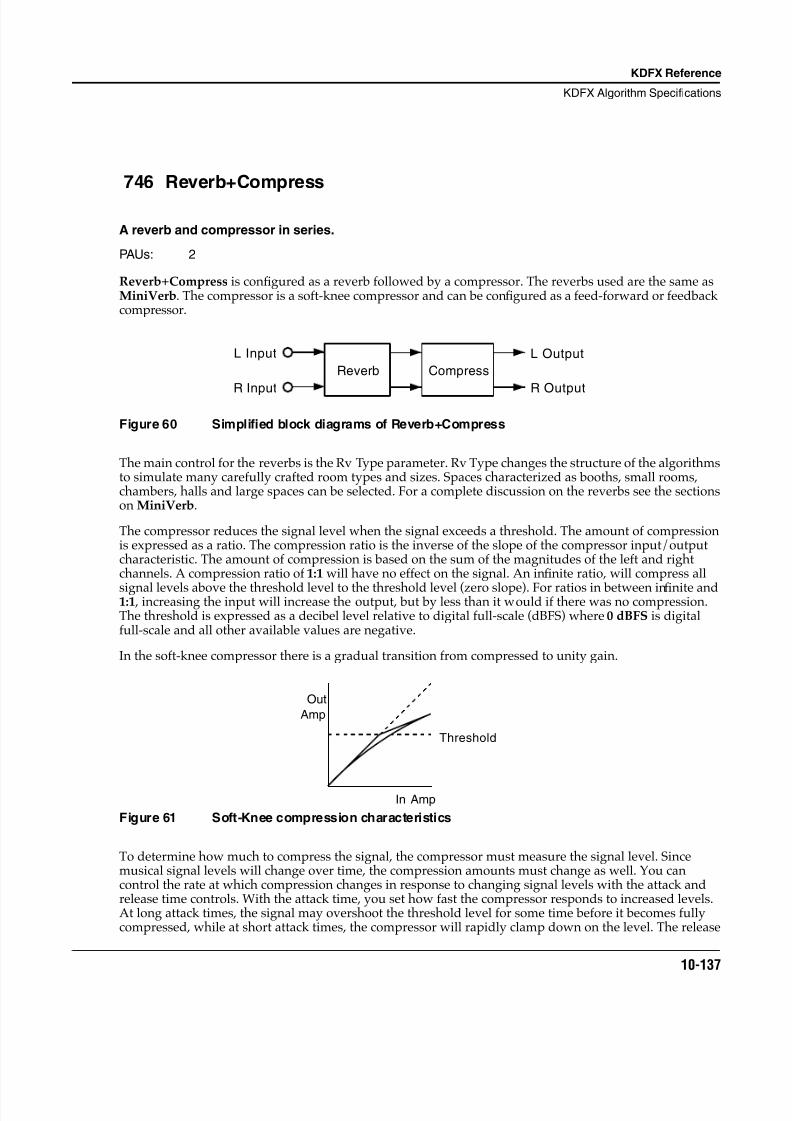
8/21/2019 MR_K2661
http://slidepdf.com/reader/full/mrk2661 219/499
KDFX Reference
KDFX Algorithm Specifications
10-137
746 Reverb+Compress
A reverb and compressor in series.
PAUs: 2
Reverb+Compress is configured as a reverb followed by a compressor. The reverbs used are the same asMiniVerb. The compressor is a soft-knee compressor and can be configured as a feed-forward or feedbackcompressor.
Figure 60 Simplified block diagrams of Reverb+Compress
The main control for the reverbs is the Rv Type parameter. Rv Type changes the structure of the algorithmsto simulate many carefully crafted room types and sizes. Spaces characterized as booths, small rooms,chambers, halls and large spaces can be selected. For a complete discussion on the reverbs see the sectionson MiniVerb.
The compressor reduces the signal level when the signal exceeds a threshold. The amount of compressionis expressed as a ratio. The compression ratio is the inverse of the slope of the compressor input/outputcharacteristic. The amount of compression is based on the sum of the magnitudes of the left and rightchannels. A compression ratio of 1:1 will have no effect on the signal. An infinite ratio, will compress all
signal levels above the threshold level to the threshold level (zero slope). For ratios in between infinite and1:1 , increasing the input will increase the output, but by less than it would if there was no compression.The threshold is expressed as a decibel level relative to digital full-scale (dBFS) where 0 dBFS is digitalfull-scale and all other available values are negative.
In the soft-knee compressor there is a gradual transition from compressed to unity gain.
Figure 61 Soft-Knee compression characteristics
To determine how much to compress the signal, the compressor must measure the signal level. Sincemusical signal levels will change over time, the compression amounts must change as well. You cancontrol the rate at which compression changes in response to changing signal levels with the attack andrelease time controls. With the attack time, you set how fast the compressor responds to increased levels.At long attack times, the signal may overshoot the threshold level for some time before it becomes fullycompressed, while at short attack times, the compressor will rapidly clamp down on the level. The release
L Input
R Input
Reverb Compress
L Output
R Output
Out
Amp
In Amp
Threshold
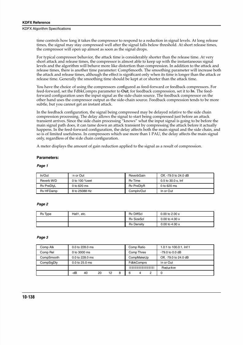
8/21/2019 MR_K2661
http://slidepdf.com/reader/full/mrk2661 220/499
10-138
KDFX Reference
KDFX Algorithm Specifications
time controls how long it takes the compressor to respond to a reduction in signal levels. At long releasetimes, the signal may stay compressed well after the signal falls below threshold. At short release times,the compressor will open up almost as soon as the signal drops.
For typical compressor behavior, the attack time is considerably shorter than the release time. At veryshort attack and release times, the compressor is almost able to keep up with the instantaneous signallevels and the algorithm will behave more like distortion than compression. In addition to the attack andrelease times, there is another time parameter: CompSmooth. The smoothing parameter will increase boththe attack and release times, although the effect is significant only when its time is longer than the attack orrelease time. Generally the smoothing time should be kept at or shorter than the attack time.
You have the choice of using the compressors configured as feed-forward or feedback compressors. Forfeed-forward, set the FdbkComprs parameter to Out; for feedback compression, set it to In. The feed-forward configuration uses the input signal as the side-chain source. The feedback compressor on theother hand uses the compressor output as the side-chain source. Feedback compression tends to be moresubtle, but you cannot get an instant attack.
In the feedback configuration, the signal being compressed may be delayed relative to the side chaincompression processing. The delay allows the signal to start being compressed just before an attack
transient arrives. Since the side chain processing “knows” what the input signal is going to be before themain signal path does, it can tame down an attack transient by compressing the attack before it actuallyhappens. In the feed-forward configuration, the delay affects both the main signal and the side chain, andso is of limited usefulness. In compressors which use more than 1 PAU, the delay affects the main signalonly, regardless of the side chain configuration.
A meter displays the amount of gain reduction applied to the signal as a result of compression.
Parameters:
Page 1
Page 2
Page 3
In/Out In or Out ReverbGain Off, -79.0 to 24.0 dB
Reverb W/D 0 to 100 %wet Rv Time 0.5 to 30.0 s, InfRv PreDlyL 0 to 620 ms Rv PreDlyR 0 to 620 ms
Rv HFDamp 8 to 25088 Hz CompIn/Out In or Out
Rv Type Hall1, etc. Rv DiffScl 0.00 to 2.00 x
Rv SizeScl 0.00 to 4.00 x
Rv Density 0.00 to 4.00 x
Comp Atk 0.0 to 228.0 ms Comp Ratio 1.0:1 to 100.0:1, Inf:1
Comp Rel 0 to 3000 ms Comp Thres -79.0 to 0.0 dB
CompSmooth 0.0 to 228.0 ms CompMakeUp Off, -79.0 to 24.0 dB
CompSigDly 0.0 to 25.0 ms FdbkComprs In or Out
|||||||||||||||||||||||||||||| Reduction
-dB 40 20 12 8 6 4 2 0
8/21/2019 MR_K2661
http://slidepdf.com/reader/full/mrk2661 221/499
KDFX Reference
KDFX Algorithm Specifications
10-139
In/Out When set to In the overall algorithm is active; when set to Out the algorithm is bypassed.
ReverbW/D This is a simple mix of the reverb input (dry) with the reverb output (wet) to produce thefinal reverb output.
ReverbGain An overall level control of the reverb’s output (applied after the reverb Wet/Dry mix).
Rv HFDamp Reduces high frequency components of the reverb above the displayed cutoff frequency.Removing higher reverb frequencies can often make rooms sound more natural.
Rv PreDlyL/R The delay between the start of a sound and the output of the first reverb reflections fromthat sound. Longer predelays can help make larger spaces sound more realistic. Longertimes can also help improve the clarity of a mix by separating the reverb signal from thedry signal, so the dry signal is not obscured. Likewise, the wet signal will be more audibleif delayed, and thus you can get by with a dryer mix while maintaining the samesubjective wet/dry level.
CompIn/Out When set to In the compressor is active; when set to Out the compressor is bypassed.
Rv Type Changes the configuration of the reverb algorithm to simulate a wide array of carefullydesigned room types and sizes. This parameter effectively allows you to have severaldifferent reverb algorithms only a parameter change away. Smaller Rv Types will sound best with shorter Rv Times, and vice versa. (Note that since this parameter changes thestructure of the reverb algorithm, you may not modulate it.)
Comp Atk The time for the compressor to start to cut in when there is an increase in signal level(attack) above the threshold.
Comp Rel The time for the compressor to stop compressing when there is a reduction in signal level(release) from a signal level above the threshold.
CompSmooth A lowpass filter in the control signal path. It is intended to smooth the output of theexpander’s envelope detector. Smoothing will affect the attack or release times when thesmoothing time is longer than one of the other times.
CompSigDly The time in ms by which the input signal should be delayed with respect to compressorside chain processing (i.e. side chain predelay). This allows the compression to appear totake effect just before the signal actually rises.
Comp Ratio The compression ratio. High ratios are highly compressed; low ratios are moderatelycompressed.
Comp Thres The threshold level in dBFS (decibels relative to full scale) above which the signal beginsto be compressed.
CompMakeUp Provides an additional control of the output gain. The Out Gain and MakeUpGaincontrols are additive (in decibels) and together may provide a maximum of 24 dB boost tooffset gain reduction due to compression.
FdbkComprs A switch to set whether the compressor side chain is configured for feed-forward (Out) orfeedback (In).
8/21/2019 MR_K2661
http://slidepdf.com/reader/full/mrk2661 222/499
10-140
KDFX Reference
KDFX Algorithm Specifications
781 St Chorus+Delay
784 St Flange+Delay
Combination effect algorithms using time/frequency units instead of tempo
PAUs: 1 or 2
The algorithms listed here are identical in most respects to combination effects elsewhere documented. Forexample, St Chorus+Delay is closely based on Chorus+Delay. The difference for algorithms with “St” inthe name is that they use stereo controls (ganged controls) rather than dual mono controls for the chorusand flange components of the algorithms.
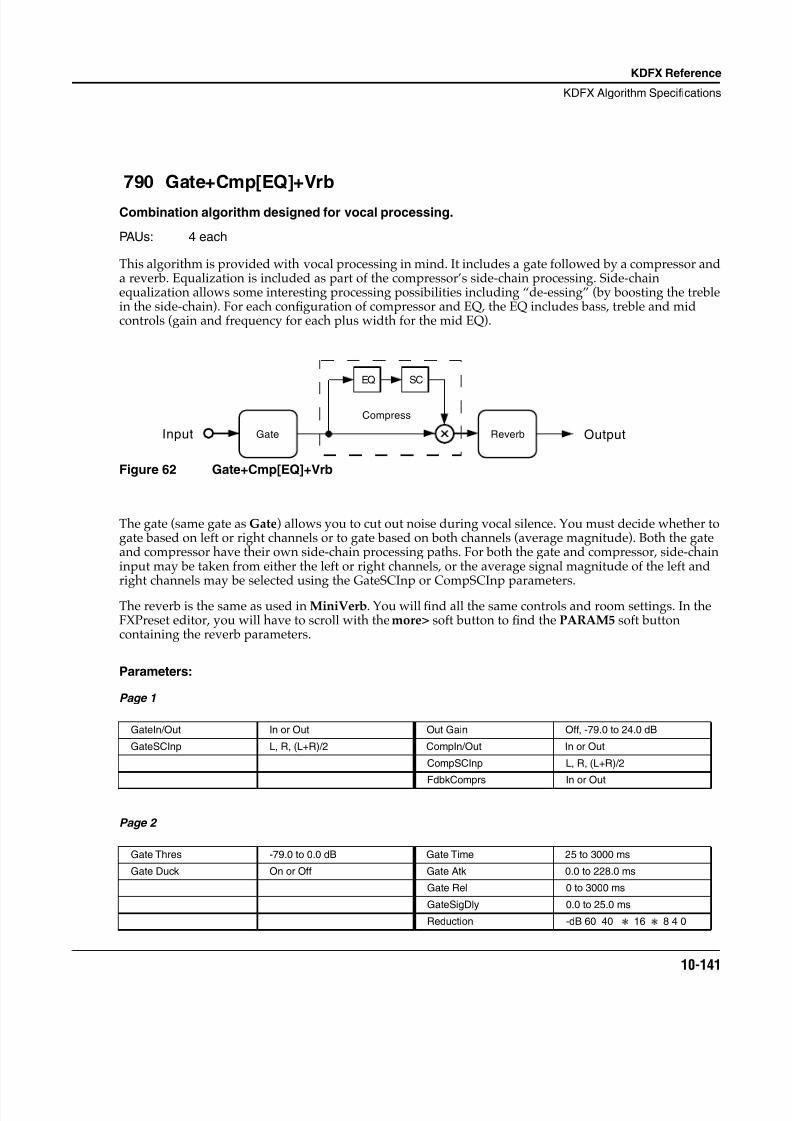
8/21/2019 MR_K2661
http://slidepdf.com/reader/full/mrk2661 223/499
KDFX Reference
KDFX Algorithm Specifications
10-141
790 Gate+Cmp[EQ]+Vrb
Combination algorithm designed for vocal processing.
PAUs: 4 each
This algorithm is provided with vocal processing in mind. It includes a gate followed by a compressor anda reverb. Equalization is included as part of the compressor’s side-chain processing. Side-chainequalization allows some interesting processing possibilities including “de-essing” (by boosting the treblein the side-chain). For each configuration of compressor and EQ, the EQ includes bass, treble and midcontrols (gain and frequency for each plus width for the mid EQ).
Figure 62 Gate+Cmp[EQ]+Vrb
The gate (same gate as Gate) allows you to cut out noise during vocal silence. You must decide whether togate based on left or right channels or to gate based on both channels (average magnitude). Both the gateand compressor have their own side-chain processing paths. For both the gate and compressor, side-chaininput may be taken from either the left or right channels, or the average signal magnitude of the left andright channels may be selected using the GateSCInp or CompSCInp parameters.
The reverb is the same as used in MiniVerb. You will find all the same controls and room settings. In theFXPreset editor, you will have to scroll with the more> soft button to find the PARAM5 soft buttoncontaining the reverb parameters.
Parameters:
Page 1
Page 2
GateIn/Out In or Out Out Gain Off, -79.0 to 24.0 dB
GateSCInp L, R, (L+R)/2 CompIn/Out In or Out
CompSCInp L, R, (L+R)/2
FdbkComprs In or Out
Gate Thres -79.0 to 0.0 dB Gate Time 25 to 3000 ms
Gate Duck On or Off Gate Atk 0.0 to 228.0 ms
Gate Rel 0 to 3000 ms
GateSigDly 0.0 to 25.0 ms
Reduction -dB 60 40 16 8 4 0
Input Gate Reverb Output
EQ SC
Compress
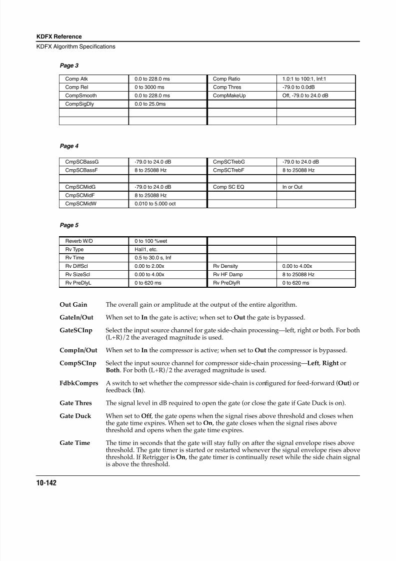
8/21/2019 MR_K2661
http://slidepdf.com/reader/full/mrk2661 224/499
10-142
KDFX Reference
KDFX Algorithm Specifications
Page 3
Page 4
Page 5
Out Gain The overall gain or amplitude at the output of the entire algorithm.
GateIn/Out When set to In the gate is active; when set to Out the gate is bypassed.
GateSCInp Select the input source channel for gate side-chain processing—left, right or both. For both(L+R)/2 the averaged magnitude is used.
CompIn/Out When set to In the compressor is active; when set to Out the compressor is bypassed.
CompSCInp Select the input source channel for compressor side-chain processing—Left , Right orBoth. For both (L+R)/2 the averaged magnitude is used.
FdbkComprs A switch to set whether the compressor side-chain is configured for feed-forward (Out) or
feedback (In).Gate Thres The signal level in dB required to open the gate (or close the gate if Gate Duck is on).
Gate Duck When set to Off , the gate opens when the signal rises above threshold and closes whenthe gate time expires. When set to On , the gate closes when the signal rises abovethreshold and opens when the gate time expires.
Gate Time The time in seconds that the gate will stay fully on after the signal envelope rises abovethreshold. The gate timer is started or restarted whenever the signal envelope rises abovethreshold. If Retrigger is On , the gate timer is continually reset while the side chain signalis above the threshold.
Comp Atk 0.0 to 228.0 ms Comp Ratio 1.0:1 to 100:1, Inf:1
Comp Rel 0 to 3000 ms Comp Thres -79.0 to 0.0dB
CompSmooth 0.0 to 228.0 ms CompMakeUp Off, -79.0 to 24.0 dBCompSigDly 0.0 to 25.0ms
CmpSCBassG -79.0 to 24.0 dB CmpSCTrebG -79.0 to 24.0 dB
CmpSCBassF 8 to 25088 Hz CmpSCTrebF 8 to 25088 Hz
CmpSCMidG -79.0 to 24.0 dB Comp SC EQ In or Out
CmpSCMidF 8 to 25088 HzCmpSCMidW 0.010 to 5.000 oct
Reverb W/D 0 to 100 %wet
Rv Type Hall1, etc.
Rv Time 0.5 to 30.0 s, Inf
Rv DiffScl 0.00 to 2.00x Rv Density 0.00 to 4.00x
Rv SizeScl 0.00 to 4.00x Rv HF Damp 8 to 25088 Hz
Rv PreDlyL 0 to 620 ms Rv PreDlyR 0 to 620 ms
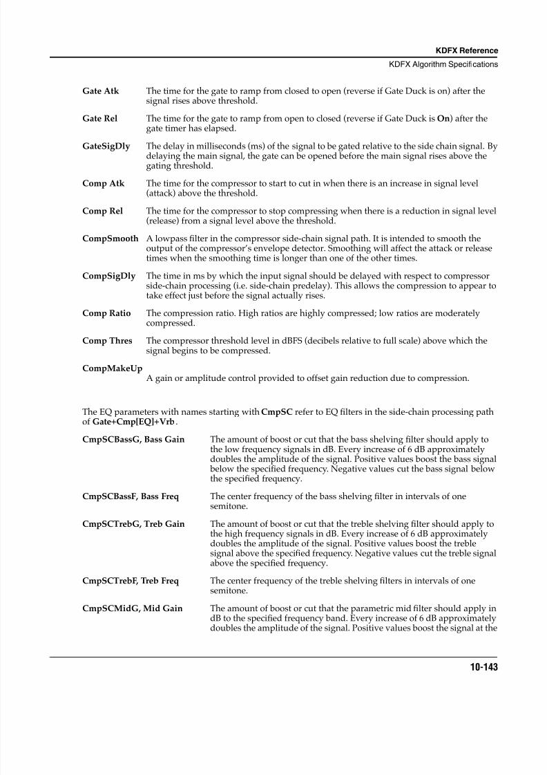
8/21/2019 MR_K2661
http://slidepdf.com/reader/full/mrk2661 225/499
KDFX Reference
KDFX Algorithm Specifications
10-143
Gate Atk The time for the gate to ramp from closed to open (reverse if Gate Duck is on) after thesignal rises above threshold.
Gate Rel The time for the gate to ramp from open to closed (reverse if Gate Duck is On) after thegate timer has elapsed.
GateSigDly The delay in milliseconds (ms) of the signal to be gated relative to the side chain signal. Bydelaying the main signal, the gate can be opened before the main signal rises above thegating threshold.
Comp Atk The time for the compressor to start to cut in when there is an increase in signal level(attack) above the threshold.
Comp Rel The time for the compressor to stop compressing when there is a reduction in signal level(release) from a signal level above the threshold.
CompSmooth A lowpass filter in the compressor side-chain signal path. It is intended to smooth theoutput of the compressor’s envelope detector. Smoothing will affect the attack or releasetimes when the smoothing time is longer than one of the other times.
CompSigDly The time in ms by which the input signal should be delayed with respect to compressorside-chain processing (i.e. side-chain predelay). This allows the compression to appear totake effect just before the signal actually rises.
Comp Ratio The compression ratio. High ratios are highly compressed; low ratios are moderatelycompressed.
Comp Thres The compressor threshold level in dBFS (decibels relative to full scale) above which thesignal begins to be compressed.
CompMakeUpA gain or amplitude control provided to offset gain reduction due to compression.
The EQ parameters with names starting with CmpSC refer to EQ filters in the side-chain processing pathof Gate+Cmp[EQ]+Vrb.
CmpSCBassG, Bass Gain The amount of boost or cut that the bass shelving filter should apply tothe low frequency signals in dB. Every increase of 6 dB approximatelydoubles the amplitude of the signal. Positive values boost the bass signal below the specified frequency. Negative values cut the bass signal belowthe specified frequency.
CmpSCBassF, Bass Freq The center frequency of the bass shelving filter in intervals of onesemitone.
CmpSCTrebG, Treb Gain The amount of boost or cut that the treble shelving filter should apply tothe high frequency signals in dB. Every increase of 6 dB approximately
doubles the amplitude of the signal. Positive values boost the treblesignal above the specified frequency. Negative values cut the treble signalabove the specified frequency.
CmpSCTrebF, Treb Freq The center frequency of the treble shelving filters in intervals of onesemitone.
CmpSCMidG, Mid Gain The amount of boost or cut that the parametric mid filter should apply indB to the specified frequency band. Every increase of 6 dB approximatelydoubles the amplitude of the signal. Positive values boost the signal at the
8/21/2019 MR_K2661
http://slidepdf.com/reader/full/mrk2661 226/499
10-144
KDFX Reference
KDFX Algorithm Specifications
specified frequency. Negative values cut the signal at the specifiedfrequency.
CmpSCMidF, Mid Freq The center frequency of the parametric mid filter in intervals of onesemitone. The boost or cut will be at a maximum at this frequency.
CmpSCMidW, Mid Width The bandwidth of the side chain parametric mid filter may be adjusted.You specify the bandwidth in octaves. Small values result in a verynarrow filter response. Large values result in a very broad response.
Reverb W/D A simple mix of the reverb sound with the dry (compressed) sound.
Rv PreDlyL/R The delay between the start of a sound and the output of the first reverbreflections from that sound. Longer predelays can help make largerspaces sound more realistic. Longer times can also help improve theclarity of a mix by separating the reverb signal from the dry signal, so thedry signal is not obscured. Likewise, the wet signal will be more audibleif delayed, and thus you can get by with a dryer mix while maintainingthe same subjective wet/dry level.
Rv Time The reverb time displayed is accurate for normal settings of the otherparameters (HF Damping = 25088 kHz , and Rv DiffScl, Rv SizeScl andRv Density = 1.00x). Changing Rv Time to Inf creates an infinitelysustaining reverb.
Rv Type Changes the configuration of the reverb algorithm to simulate a widearray of carefully designed room types and sizes. This parametereffectively allows you to have several different reverb algorithms only aparameter change away. Smaller Rv Types will sound best with shorterRv Times, and vice versa. (Note that since this parameter changes thestructure of the reverb algorithm, you may not modulate it.)
Rv HF Damp Reduces high frequency components of the reverb above the displayedcutoff frequency. Removing higher reverb frequencies can often makerooms sound more natural.
Rv DiffScl A multiplier which affects the diffusion of the reverb. At 1.00x , thediffusion will be the normal, carefully adjusted amount for the currentRv Type. Altering this parameter will change the diffusion from thepreset amount.
Rv SizeScl A multiplier which changes the reverb size of the current room. At 1.00x ,the room will be the normal, carefully tweaked size of the currentRv Type. Altering this parameter will change the size of the room, andthus will cause a subtle coloration of the reverb (since the room’sdimensions are changing).
Rv Density A multiplier which affects the density of the reverb. At 1.00x , the room
density will be the normal, carefully set amount for the current Rv Type.Altering this parameter will change the density of the reverb, which maycolor the room slightly.
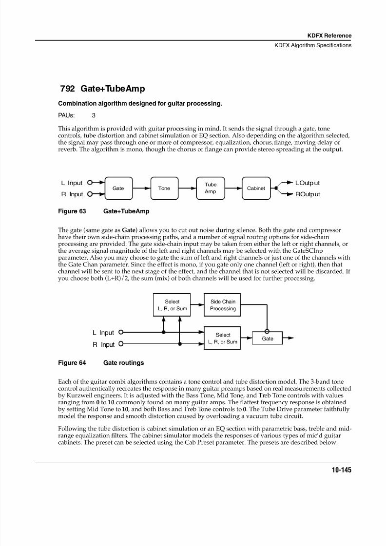
8/21/2019 MR_K2661
http://slidepdf.com/reader/full/mrk2661 227/499
KDFX Reference
KDFX Algorithm Specifications
10-145
792 Gate+TubeAmp
Combination algorithm designed for guitar processing.
PAUs: 3
This algorithm is provided with guitar processing in mind. It sends the signal through a gate, tonecontrols, tube distortion and cabinet simulation or EQ section. Also depending on the algorithm selected,the signal may pass through one or more of compressor, equalization, chorus, flange, moving delay orreverb. The algorithm is mono, though the chorus or flange can provide stereo spreading at the output.
Figure 63 Gate+TubeAmp
The gate (same gate as Gate) allows you to cut out noise during silence. Both the gate and compressorhave their own side-chain processing paths, and a number of signal routing options for side-chainprocessing are provided. The gate side-chain input may be taken from either the left or right channels, orthe average signal magnitude of the left and right channels may be selected with the GateSCInpparameter. Also you may choose to gate the sum of left and right channels or just one of the channels withthe Gate Chan parameter. Since the effect is mono, if you gate only one channel (left or right), then thatchannel will be sent to the next stage of the effect, and the channel that is not selected will be discarded. Ifyou choose both (L+R)/2, the sum (mix) of both channels will be used for further processing.
Figure 64 Gate routings
Each of the guitar combi algorithms contains a tone control and tube distortion model. The 3-band tonecontrol authentically recreates the response in many guitar preamps based on real measurements collected by Kurzweil engineers. It is adjusted with the Bass Tone, Mid Tone, and Treb Tone controls with valuesranging from 0 to 10 commonly found on many guitar amps. The flattest frequency response is obtained by setting Mid Tone to 10 , and both Bass and Treb Tone controls to 0. The Tube Drive parameter faithfullymodel the response and smooth distortion caused by overloading a vacuum tube circuit.
Following the tube distortion is cabinet simulation or an EQ section with parametric bass, treble and mid-range equalization filters. The cabinet simulator models the responses of various types of mic’d guitarcabinets. The preset can be selected using the Cab Preset parameter. The presets are described below.
L Input
R InputGate Tone
Tube
AmpCabinet
L Output
R Output
L Input
R Input
Select
L, R, or Sum
Select
L, R, or Sum
Side Chain
Processing
Gate
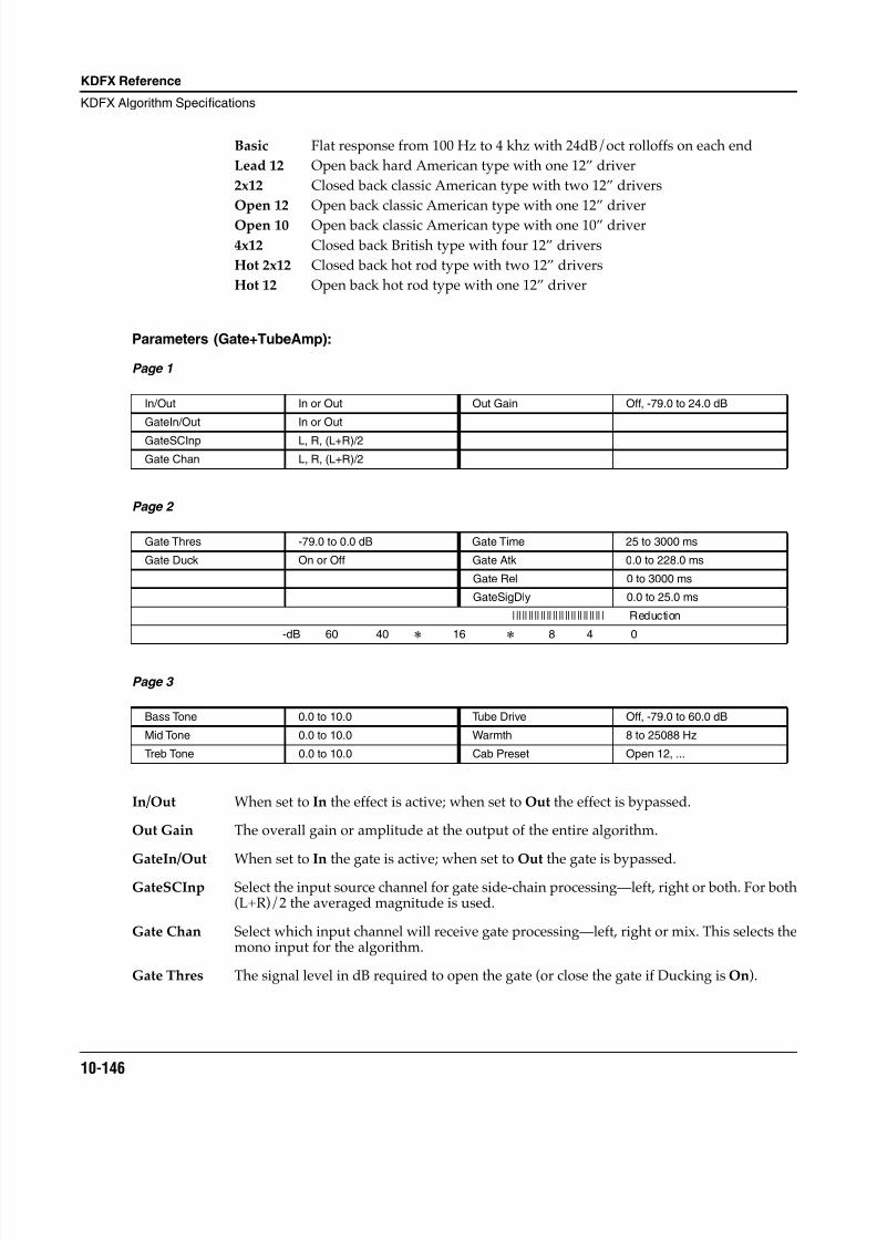
8/21/2019 MR_K2661
http://slidepdf.com/reader/full/mrk2661 228/499
10-146
KDFX Reference
KDFX Algorithm Specifications
Basic Flat response from 100 Hz to 4 khz with 24dB/oct rolloffs on each end
Lead 12 Open back hard American type with one 12” driver
2x12 Closed back classic American type with two 12” drivers
Open 12 Open back classic American type with one 12” driver
Open 10 Open back classic American type with one 10” driver
4x12 Closed back British type with four 12” drivers
Hot 2x12 Closed back hot rod type with two 12” drivers
Hot 12 Open back hot rod type with one 12” driver
Parameters (Gate+TubeAmp):
Page 1
Page 2
Page 3
In/Out When set to In the effect is active; when set to Out the effect is bypassed.
Out Gain The overall gain or amplitude at the output of the entire algorithm.
GateIn/Out When set to In the gate is active; when set to Out the gate is bypassed.
GateSCInp Select the input source channel for gate side-chain processing—left, right or both. For both(L+R)/2 the averaged magnitude is used.
Gate Chan Select which input channel will receive gate processing—left, right or mix. This selects themono input for the algorithm.
Gate Thres The signal level in dB required to open the gate (or close the gate if Ducking is On).
In/Out In or Out Out Gain Off, -79.0 to 24.0 dB
GateIn/Out In or Out
GateSCInp L, R, (L+R)/2
Gate Chan L, R, (L+R)/2
Gate Thres -79.0 to 0.0 dB Gate Time 25 to 3000 ms
Gate Duck On or Off Gate Atk 0.0 to 228.0 ms
Gate Rel 0 to 3000 ms
GateSigDly 0.0 to 25.0 ms
|||||||||||||||||||||||||||||| Reduction
-dB 60 40 16 8 4 0
Bass Tone 0.0 to 10.0 Tube Drive Off, -79.0 to 60.0 dB
Mid Tone 0.0 to 10.0 Warmth 8 to 25088 Hz
Treb Tone 0.0 to 10.0 Cab Preset Open 12, ...
8/21/2019 MR_K2661
http://slidepdf.com/reader/full/mrk2661 229/499
KDFX Reference
KDFX Algorithm Specifications
10-147
Gate Duck When set to Off , the gate opens when the signal rises above threshold and closes whenthe gate time expires. When set to On , the gate closes when the signal rises abovethreshold and opens when the gate time expires.
Gate Time The time in seconds that the gate will stay fully on after the signal envelope rises abovethreshold. The gate timer is started or restarted whenever the signal envelope rises abovethreshold.
Gate Atk The time for the gate to ramp from closed to open (reverse if Gate Duck is On) after thesignal rises above threshold.
Gate Rel The time for the gate to ramp from open to closed (reverse if Gate Duck is On) after thegate timer has elapsed.
GateSigDly The delay in milliseconds (ms) of the signal to be gated relative to the side chain signal. Bydelaying the main signal, the gate can be opened before the main signal rises above thegating threshold.
Tube Drive Adjusts the gain into the distortion circuit. Higher values produce more distortion.
Cab Preset Eight preset cabinets have been created based on measurements of real guitar amplifiercabinets. The presets are Basic , Lead 12 , 2x12 , Open 12 , Open 10 , 4x12 , Hot 2x12 , andHot 12.
Warmth Adjusts a 1 pole (6dB/oct) lowpass filter applied after distortion.
Bass Tone
Mid ToneTreb Tone
Adjusts the three bands of tone control integrated with the distortion drive circuit.
Flattest response is obtained by setting Mid Tone to 10.0 and both Bass Tone andTreb Tone to 0.0.
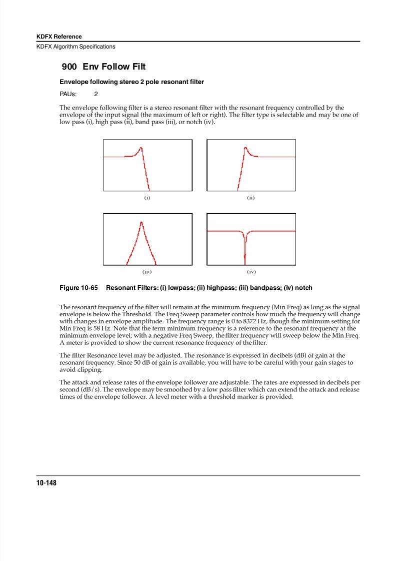
8/21/2019 MR_K2661
http://slidepdf.com/reader/full/mrk2661 230/499
10-148
KDFX Reference
KDFX Algorithm Specifications
900 Env Follow Filt
Envelope following stereo 2 pole resonant filter
PAUs: 2
The envelope following filter is a stereo resonant filter with the resonant frequency controlled by theenvelope of the input signal (the maximum of left or right). The filter type is selectable and may be one oflow pass (i), high pass (ii), band pass (iii), or notch (iv).
Figure 10-65 Resonant Filters: (i) lowpass; (ii) highpass; (iii) bandpass; (iv) notch
The resonant frequency of the filter will remain at the minimum frequency (Min Freq) as long as the signalenvelope is below the Threshold. The Freq Sweep parameter controls how much the frequency will changewith changes in envelope amplitude. The frequency range is 0 to 8372 Hz, though the minimum setting forMin Freq is 58 Hz. Note that the term minimum frequency is a reference to the resonant frequency at theminimum envelope level; with a negative Freq Sweep, the filter frequency will sweep below the Min Freq.A meter is provided to show the current resonance frequency of the filter.
The filter Resonance level may be adjusted. The resonance is expressed in decibels (dB) of gain at theresonant frequency. Since 50 dB of gain is available, you will have to be careful with your gain stages toavoid clipping.
The attack and release rates of the envelope follower are adjustable. The rates are expressed in decibels per
second (dB/s). The envelope may be smoothed by a low passfi
lter which can extend the attack and releasetimes of the envelope follower. A level meter with a threshold marker is provided.
(i) (ii)
(iii) (iv)
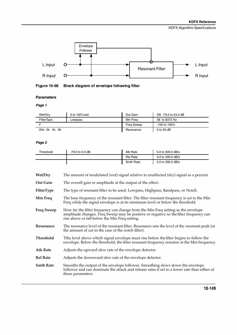
8/21/2019 MR_K2661
http://slidepdf.com/reader/full/mrk2661 231/499
KDFX Reference
KDFX Algorithm Specifications
10-149
Figure 10-66 Block diagram of envelope following filter
Parameters
Page 1
Page 2
Wet/Dry The amount of modulated (wet) signal relative to unaffected (dry) signal as a percent.Out Gain The overall gain or amplitude at the output of the effect.
FilterType The type of resonant filter to be used. Lowpass, Highpass, Bandpass, or Notch.
Min Freq The base frequency of the resonant filter. The filter resonant frequency is set to the MinFreq while the signal envelope is at its minimum level or below the threshold.
Freq Sweep How far the filter frequency can change from the Min Freq setting as the envelopeamplitude changes. Freq Sweep may be positive or negative so the filter frequency canrise above or fall below the Min Freq setting.
Resonance The resonance level of the resonant filter. Resonance sets the level of the resonant peak (orthe amount of cut in the case of the notch filter).
Threshold Tthe level above which signal envelope must rise before the filter begins to follow theenvelope. Below the threshold, the filter resonant frequency remains at the Min frequency.
Atk Rate Adjusts the upward slew rate of the envelope detector.
Rel Rate Adjusts the downward slew rate of the envelope detector.
Smth Rate Smooths the output of the envelope follower. Smoothing slows down the envelopefollower and can dominate the attack and release rates if set to a lower rate than either ofthese parameters.
Wet/Dry 0 to 100%wet Out Gain Off, -79.0 to 24.0 dB
FilterType Lowpass Min Freq 58 to 8372 Hz
F Freq Sweep -100 to 100%
0Hz 2k 4k 6k Resonance 0 to 50 dB
Threshold -79.0 to 0.0 dB Atk Rate 0.0 to 300.0 dB/s
Rel Rate 0.0 to 300.0 dB/s
Smth Rate 0.0 to 300.0 dB/s
R Input
L Input
Envelope
Follower
Resonant Filter
R Input
L Input
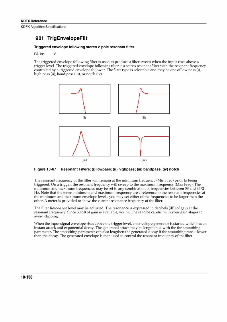
8/21/2019 MR_K2661
http://slidepdf.com/reader/full/mrk2661 232/499
10-150
KDFX Reference
KDFX Algorithm Specifications
901 TrigEnvelopeFilt
Triggered envelope following stereo 2 pole resonant filter
PAUs: 2
The triggered envelope following filter is used to produce a filter sweep when the input rises above atrigger level. The triggered envelope following filter is a stereo resonant filter with the resonant frequencycontrolled by a triggered envelope follower. The filter type is selectable and may be one of low pass (i),high pass (ii), band pass (iii), or notch (iv).
Figure 10-67 Resonant Filters: (i) lowpass; (ii) highpass; (iii) bandpass; (iv) notch
The resonant frequency of the filter will remain at the minimum frequency (Min Freq) prior to beingtriggered. On a trigger, the resonant frequency will sweep to the maximum frequency (Max Freq). Theminimum and maximum frequencies may be set to any combination of frequencies between 58 and 8372Hz. Note that the terms minimum and maximum frequency are a reference to the resonant frequencies atthe minimum and maximum envelope levels; you may set either of the frequencies to be larger than theother. A meter is provided to show the current resonance frequency of the filter.
The filter Resonance level may be adjusted. The resonance is expressed in decibels (dB) of gain at theresonant frequency. Since 50 dB of gain is available, you will have to be careful with your gain stages toavoid clipping.
When the input signal envelope rises above the trigger level, an envelope generator is started which has aninstant attack and exponential decay. The generated attack may be lengthened with the the smoothingparameter. The smoothing parameter can also lengthen the generated decay if the smoothing rate is lowerthan the decay. The generated envelope is then used to control the resonant frequency of the filter.
(i) (ii)
(iii) (iv)
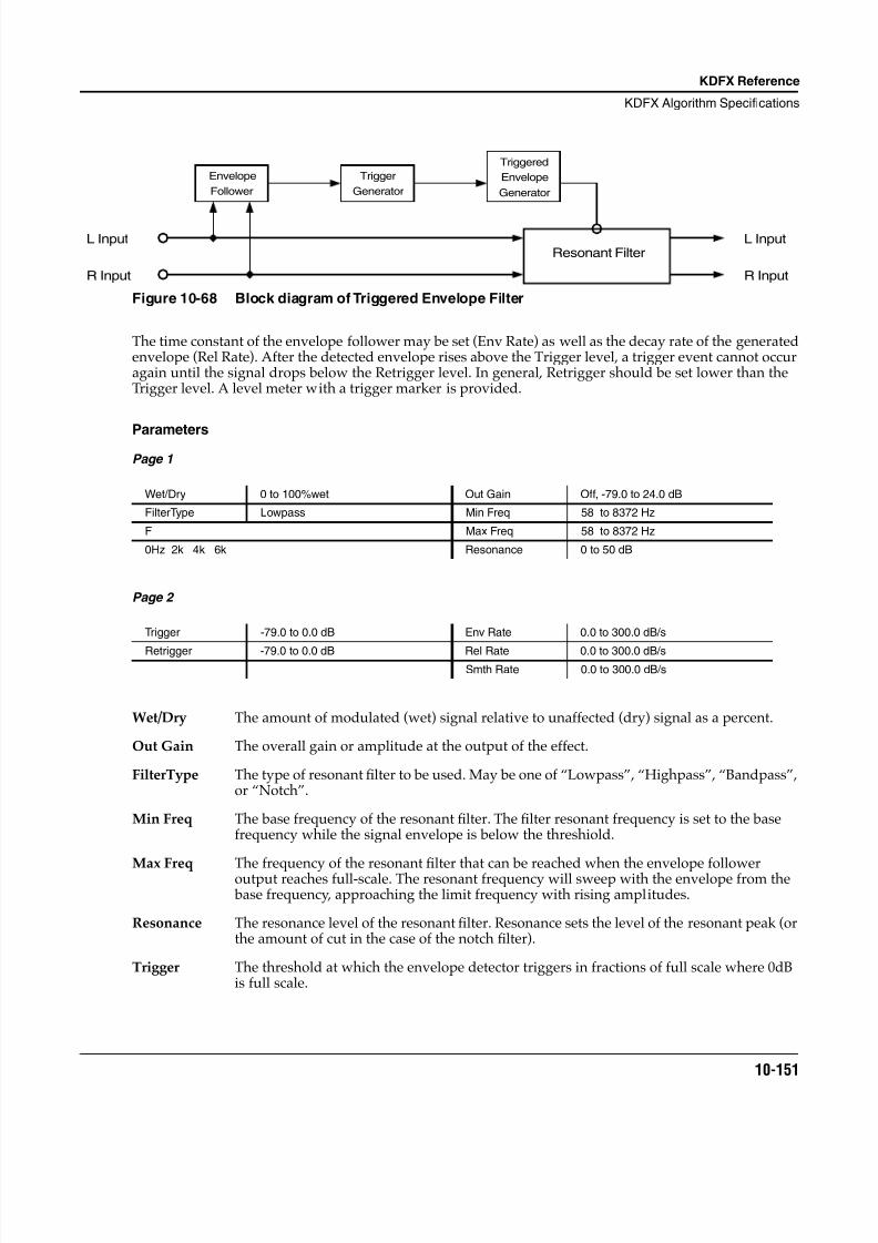
8/21/2019 MR_K2661
http://slidepdf.com/reader/full/mrk2661 233/499
KDFX Reference
KDFX Algorithm Specifications
10-151
Figure 10-68 Block diagram of Triggered Envelope Filter
The time constant of the envelope follower may be set (Env Rate) as well as the decay rate of the generatedenvelope (Rel Rate). After the detected envelope rises above the Trigger level, a trigger event cannot occuragain until the signal drops below the Retrigger level. In general, Retrigger should be set lower than theTrigger level. A level meter with a trigger marker is provided.
ParametersPage 1
Page 2
Wet/Dry The amount of modulated (wet) signal relative to unaffected (dry) signal as a percent.
Out Gain The overall gain or amplitude at the output of the effect.
FilterType The type of resonant filter to be used. May be one of “Lowpass”, “Highpass”, “Bandpass”,or “Notch”.
Min Freq The base frequency of the resonant filter. The filter resonant frequency is set to the basefrequency while the signal envelope is below the threshiold.
Max Freq The frequency of the resonantfi
lter that can be reached when the envelope followeroutput reaches full-scale. The resonant frequency will sweep with the envelope from the base frequency, approaching the limit frequency with rising amplitudes.
Resonance The resonance level of the resonant filter. Resonance sets the level of the resonant peak (orthe amount of cut in the case of the notch filter).
Trigger The threshold at which the envelope detector triggers in fractions of full scale where 0dBis full scale.
Wet/Dry 0 to 100%wet Out Gain Off, -79.0 to 24.0 dB
FilterType Lowpass Min Freq 58 to 8372 Hz
F Max Freq 58 to 8372 Hz
0Hz 2k 4k 6k Resonance 0 to 50 dB
Trigger -79.0 to 0.0 dB Env Rate 0.0 to 300.0 dB/s
Retrigger -79.0 to 0.0 dB Rel Rate 0.0 to 300.0 dB/sSmth Rate 0.0 to 300.0 dB/s
Resonant Filter
Envelope
Follower
Trigger
Generator
Triggered
Envelope
Generator
L Input
R Input
L Input
R Input
8/21/2019 MR_K2661
http://slidepdf.com/reader/full/mrk2661 234/499
10-152
KDFX Reference
KDFX Algorithm Specifications
Retrigger The threshold at which the envelope detector resets such that it can trigger again infractions of full scale where 0dB is full scale. This value is only useful when it is below thevalue of Trigger.
Env Rate The envelope detector decay rate which can be used to prevent false triggering. When thesignal envelope falls below the retrigger level, the filter can be triggered again when thesignal rises above the trigger level. Since the input signal can fluctuate rapidly, it isnecessary to adjust the rate at which the signal envelope can fall to the retrigger level. Therate is provided in decibels per second (dB/s).
Rel Rate The downward slew rate of the triggered envelope generator. The rate is provided indecibels per second (dB/s).
Smth Rate Smooths the output of the envelope generator. Smoothing slows down the envelopefollower and can dominate the release rate if set lower rate than this parameter. You canuse the smoothing rate to lengthen the attack of the generated envelope which wouldotherwise have an instant attack. The rate is provided in decibels per second (dB/s).
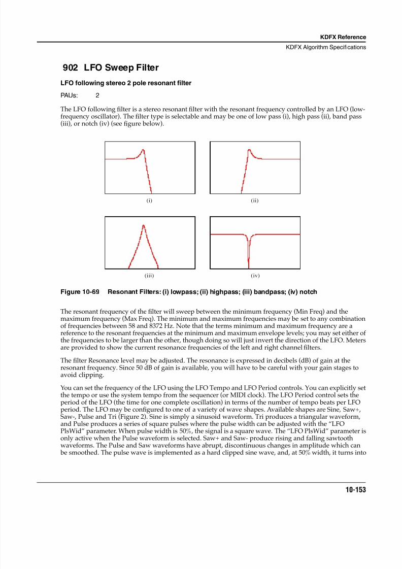
8/21/2019 MR_K2661
http://slidepdf.com/reader/full/mrk2661 235/499
KDFX Reference
KDFX Algorithm Specifications
10-153
902 LFO Sweep Filter
LFO following stereo 2 pole resonant filter
PAUs: 2
The LFO following filter is a stereo resonant filter with the resonant frequency controlled by an LFO (low-frequency oscillator). The filter type is selectable and may be one of low pass (i), high pass (ii), band pass(iii), or notch (iv) (see figure below).
Figure 10-69 Resonant Filters: (i) lowpass; (ii) highpass; (iii) bandpass; (iv) notch
The resonant frequency of the filter will sweep between the minimum frequency (Min Freq) and themaximum frequency (Max Freq). The minimum and maximum frequencies may be set to any combinationof frequencies between 58 and 8372 Hz. Note that the terms minimum and maximum frequency are areference to the resonant frequencies at the minimum and maximum envelope levels; you may set either ofthe frequencies to be larger than the other, though doing so will just invert the direction of the LFO. Metersare provided to show the current resonance frequencies of the left and right channel filters.
The filter Resonance level may be adjusted. The resonance is expressed in decibels (dB) of gain at theresonant frequency. Since 50 dB of gain is available, you will have to be careful with your gain stages toavoid clipping.
You can set the frequency of the LFO using the LFO Tempo and LFO Period controls. You can explicitly set
the tempo or use the system tempo from the sequencer (or MIDI clock). The LFO Period control sets theperiod of the LFO (the time for one complete oscillation) in terms of the number of tempo beats per LFOperiod. The LFO may be configured to one of a variety of wave shapes. Available shapes are Sine, Saw+,Saw-, Pulse and Tri (Figure 2). Sine is simply a sinusoid waveform. Tri produces a triangular waveform,and Pulse produces a series of square pulses where the pulse width can be adjusted with the “LFOPlsWid” parameter. When pulse width is 50%, the signal is a square wave. The “LFO PlsWid” parameter isonly active when the Pulse waveform is selected. Saw+ and Saw- produce rising and falling sawtoothwaveforms. The Pulse and Saw waveforms have abrupt, discontinuous changes in amplitude which can be smoothed. The pulse wave is implemented as a hard clipped sine wave, and, at 50% width, it turns into
(i) (ii)
(iii) (iv)
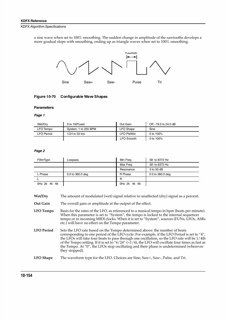
8/21/2019 MR_K2661
http://slidepdf.com/reader/full/mrk2661 236/499
10-154
KDFX Reference
KDFX Algorithm Specifications
a sine wave when set to 100% smoothing. The sudden change in amplitude of the sawtooths develops amore gradual slope with smoothing, ending up as triangle waves when set to 100% smoothing.
Figure 10-70 Configurable Wave Shapes
Parameters
Page 1
Page 2
Wet/Dry The amount of modulated (wet) signal relative to unaffected (dry) signal as a percent.
Out Gain The overall gain or amplitude at the output of the effect.
LFO Tempo Basis for the rates of the LFO, as referenced to a musical tempo in bpm (beats per minute).When this parameter is set to “System”, the tempo is locked to the internal sequencertempo or to incoming MIDI clocks. When it is set to “System”, sources (FUNs, LFOs, ASRs
etc.) will have no effect on the Tempo parameter.LFO Period Sets the LFO rate based on the Tempo determined above: the number of beats
corresponding to one period of the LFO cycle. For example, if the LFO Period is set to “4”,the LFOs will take four beats to pass through one oscillation, so the LFO rate will be 1/4thof the Tempo setting. If it is set to “6/24” (=1/4), the LFO will oscillate four times as fast asthe Tempo. At “0”, the LFOs stop oscillating and their phase is undetermined (whereverthey stopped).
LFO Shape The waveform type for the LFO. Choices are Sine, Saw+, Saw-, Pulse, and Tri.
Wet/Dry 0 to 100%wet Out Gain Off, -79.0 to 24.0 dB
LFO Tempo System, 1 to 255 BPM LFO Shape Sine
LFO Period 1/24 to 32 bts LFO PlsWid 0 to 100%
LFO Smooth 0 to 100%
FilterType Lowpass Min Freq 58 to 8372 Hz
Max Freq 58 to 8372 Hz
Resonance 0 to 50 dB
L Phase 0.0 to 360.0 deg R Phase 0.0 to 360.0 deg
L R
0Hz 2k 4k 6k 0Hz 2k 4k 6k
Sine Saw+ Saw- Pulse Tri
PulseWidth
8/21/2019 MR_K2661
http://slidepdf.com/reader/full/mrk2661 237/499
KDFX Reference
KDFX Algorithm Specifications
10-155
LFO PlsWid When the LFO Shape is set to Pulse, the PlsWid parameter sets the pulse width as apercentage of the waveform period. The pulse is a square wave when the width is set to50%. This parameter is active only when the Pulse waveform is selected.
LFO Smooth Smooths the Saw+, Saw-, and Pulse waveforms. For the sawtooth waves, smoothingmakes the waveform more like a triangle wave. For the Pulse wave, smoothing makes thewaveform more like a sine wave.
FilterType The type of resonant filter to be used. May be one of “Lowpass”, “Highpass”, “Bandpass”,or “Notch”.
Min Freq The minimum frequency of the resonant filter. This is the resonant frequency at one of theextremes of the LFO sweep. The resonant filter frequency will sweep between the MinFreq and Max Freq.
Max Freq The maximum frequency of the resonant filter. This is resonant frequency at the otherextreme of the LFO sweep. The resonant filter frequency will sweep between the Min Freqand Max Freq.
Resonance The resonance level of the resonantfi
lter. Resonance sets the level of the resonant peak (orthe amount of cut in the case of the notch filter).
L Phase The phase angle of the left channel LFO relative to the system tempo clock and the rightchannel phase.
R Phase The phase angle of the right channel LFO relative to the system tempo clock and the leftchannel phase.
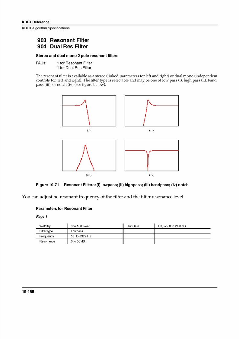
8/21/2019 MR_K2661
http://slidepdf.com/reader/full/mrk2661 238/499
10-156
KDFX Reference
KDFX Algorithm Specifications
903 Resonant Filter904 Dual Res Filter
Stereo and dual mono 2 pole resonant filters
PAUs: 1 for Resonant Filter1 for Dual Res Filter
The resonant filter is available as a stereo (linked parameters for left and right) or dual mono (independentcontrols for left and right). The filter type is selectable and may be one of low pass (i), high pass (ii), bandpass (iii), or notch (iv) (see figure below).
Figure 10-71 Resonant Filters: (i) lowpass; (ii) highpass; (iii) bandpass; (iv) notch
You can adjust he resonant frequency of the filter and the filter resonance level.
Parameters for Resonant Filter
Page 1
Wet/Dry 0 to 100%wet Out Gain Off, -79.0 to 24.0 dB
FilterType Lowpass
Frequency 58 to 8372 HzResonance 0 to 50 dB
(i) (ii)
(iii) (iv)
8/21/2019 MR_K2661
http://slidepdf.com/reader/full/mrk2661 239/499
KDFX Reference
KDFX Algorithm Specifications
10-157
Parameters for Dual Res Filter
Page 1
Page 2
Wet/Dry The amount of filtered (wet) signal relative to unaffected (dry) signal.
Out Gain The overall gain or amplitude at the output of the filter.
FilterType The type of resonant filter to be used. May be one of “Lowpass”, “Highpass”, “Bandpass”,or “Notch”.
Frequency The frequency of the resonant filter peak (or notch) in Hz. The frequencies correspond tosemitone increments.
Resonance The resonance level of the resonant filter. Resonance sets the level of the resonant peak (orthe amount of cut in the case of the notch filter).
L Wet/Dry 0 to 100%wet R Wet/Dry 0 to 100%wet
L Output Off, -79.0 to 24.0 dB R Output Off, -79.0 to 24.0 dB
L FiltType Lowpass R FiltType Highpass
L Freq 58 to 8372 Hz R Freq 58 to 8372 Hz
LResonance 0 to 50 dB RResonance 0 to 50 dB
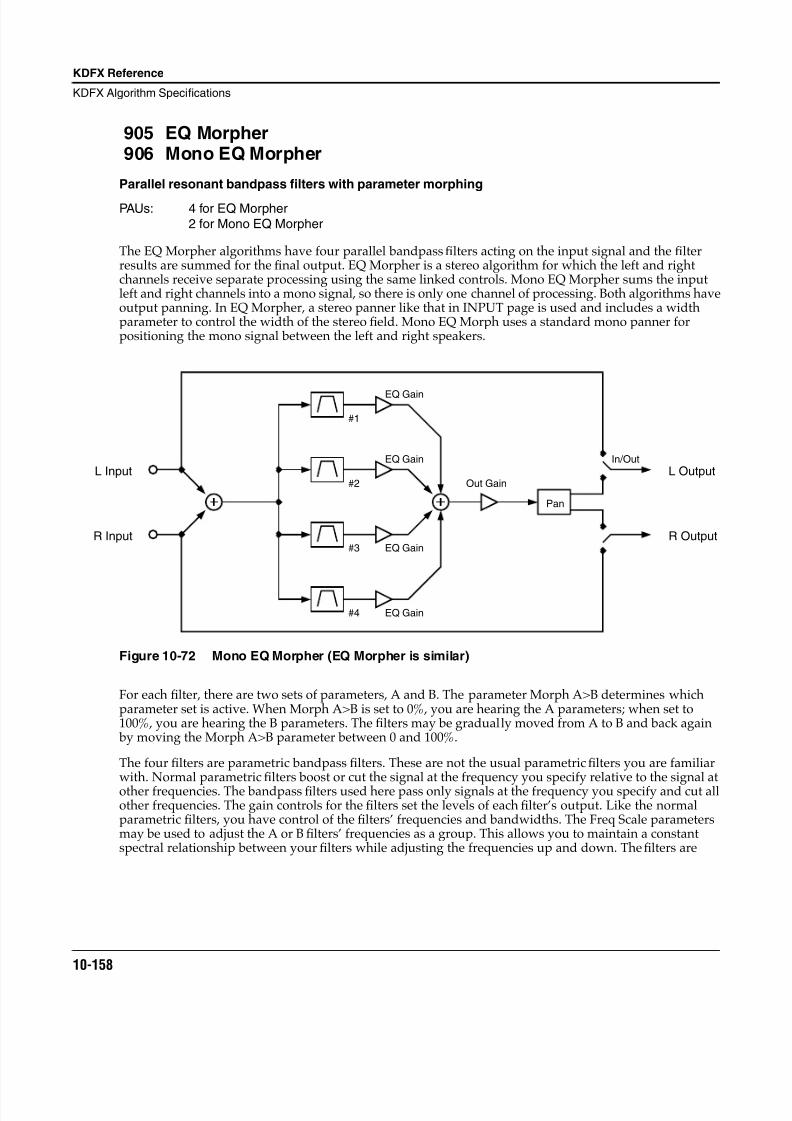
8/21/2019 MR_K2661
http://slidepdf.com/reader/full/mrk2661 240/499
10-158
KDFX Reference
KDFX Algorithm Specifications
905 EQ Morpher906 Mono EQ Morpher
Parallel resonant bandpass filters with parameter morphing
PAUs: 4 for EQ Morpher2 for Mono EQ Morpher
The EQ Morpher algorithms have four parallel bandpass filters acting on the input signal and the filterresults are summed for the final output. EQ Morpher is a stereo algorithm for which the left and rightchannels receive separate processing using the same linked controls. Mono EQ Morpher sums the inputleft and right channels into a mono signal, so there is only one channel of processing. Both algorithms haveoutput panning. In EQ Morpher, a stereo panner like that in INPUT page is used and includes a widthparameter to control the width of the stereo field. Mono EQ Morph uses a standard mono panner forpositioning the mono signal between the left and right speakers.
Figure 10-72 Mono EQ Morpher (EQ Morpher is similar)
For each filter, there are two sets of parameters, A and B. The parameter Morph A>B determines whichparameter set is active. When Morph A>B is set to 0%, you are hearing the A parameters; when set to100%, you are hearing the B parameters. The filters may be gradually moved from A to B and back again by moving the Morph A>B parameter between 0 and 100%.
The four filters are parametric bandpass filters. These are not the usual parametric filters you are familiarwith. Normal parametric filters boost or cut the signal at the frequency you specify relative to the signal atother frequencies. The bandpass filters used here pass only signals at the frequency you specify and cut allother frequencies. The gain controls for the filters set the levels of each filter’s output. Like the normalparametric filters, you have control of the filters’ frequencies and bandwidths. The Freq Scale parametersmay be used to adjust the A or B filters’ frequencies as a group. This allows you to maintain a constantspectral relationship between your filters while adjusting the frequencies up and down. The filters are
Pan
L Input
R Input
Out GainL Output
R Output
#1
#2
#3
#4
In/Out
EQ Gain
EQ Gain
EQ Gain
EQ Gain
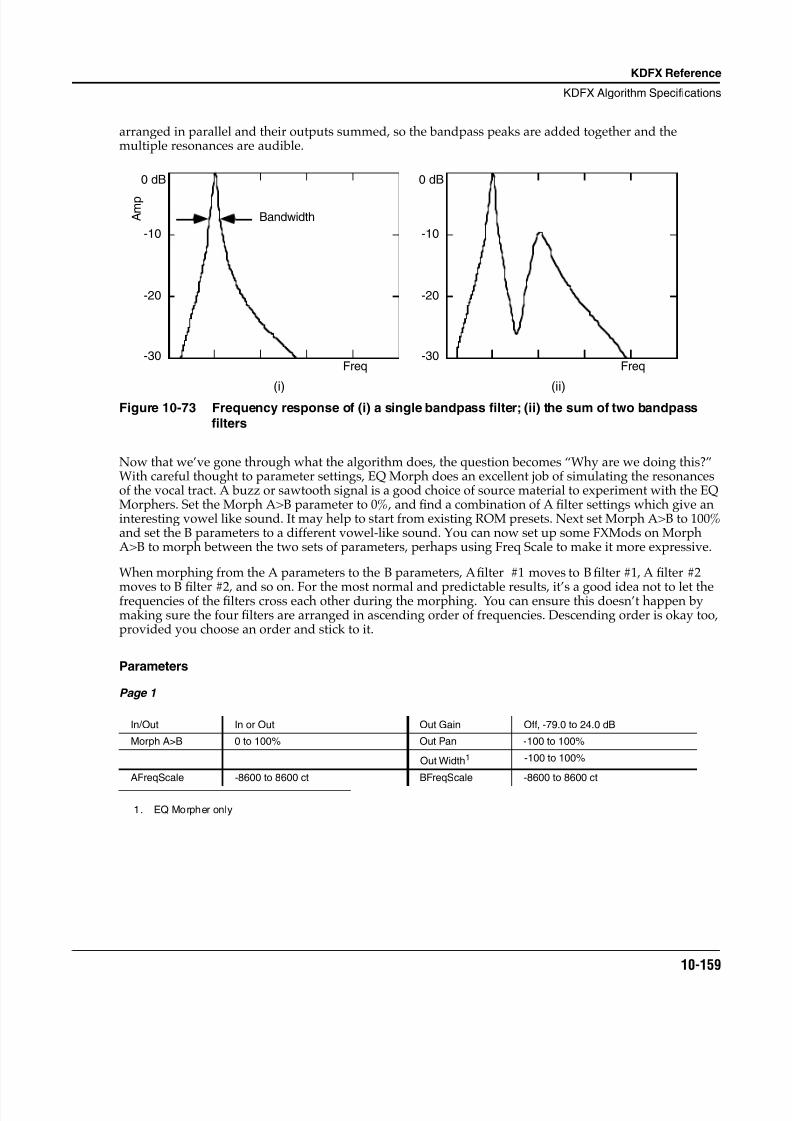
8/21/2019 MR_K2661
http://slidepdf.com/reader/full/mrk2661 241/499
KDFX Reference
KDFX Algorithm Specifications
10-159
arranged in parallel and their outputs summed, so the bandpass peaks are added together and themultiple resonances are audible.
Figure 10-73 Frequency response of (i) a single bandpass filter; (ii) the sum of two bandpass
filters
Now that we’ve gone through what the algorithm does, the question becomes “Why are we doing this?”With careful thought to parameter settings, EQ Morph does an excellent job of simulating the resonancesof the vocal tract. A buzz or sawtooth signal is a good choice of source material to experiment with the EQMorphers. Set the Morph A>B parameter to 0%, and find a combination of A filter settings which give aninteresting vowel like sound. It may help to start from existing ROM presets. Next set Morph A>B to 100%and set the B parameters to a different vowel-like sound. You can now set up some FXMods on MorphA>B to morph between the two sets of parameters, perhaps using Freq Scale to make it more expressive.
When morphing from the A parameters to the B parameters, A filter #1 moves to B filter #1, A filter #2
moves to B filter #2, and so on. For the most normal and predictable results, it’s a good idea not to let thefrequencies of the filters cross each other during the morphing. You can ensure this doesn’t happen bymaking sure the four filters are arranged in ascending order of frequencies. Descending order is okay too,provided you choose an order and stick to it.
Parameters
Page 1
In/Out In or Out Out Gain Off, -79.0 to 24.0 dB
Morph A>B 0 to 100% Out Pan -100 to 100%
Out Width1
1. EQ Morpher only
-100 to 100%
AFreqScale -8600 to 8600 ct BFreqScale -8600 to 8600 ct
(i) (ii)
Freq
A m p
0 dB
-10
-20
-30
0 dB
-10
-20
-30Freq
Bandwidth
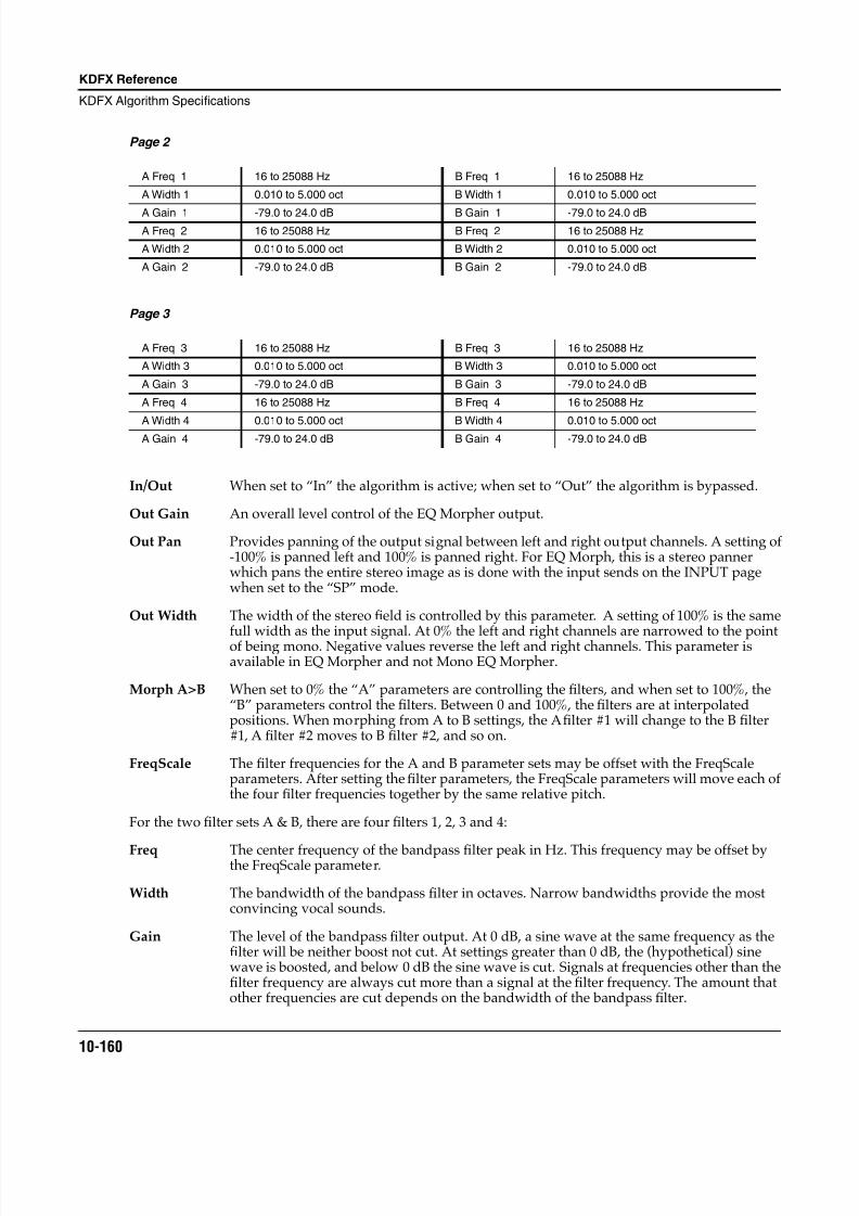
8/21/2019 MR_K2661
http://slidepdf.com/reader/full/mrk2661 242/499
10-160
KDFX Reference
KDFX Algorithm Specifications
Page 2
Page 3
In/Out When set to “In” the algorithm is active; when set to “Out” the algorithm is bypassed.
Out Gain An overall level control of the EQ Morpher output.
Out Pan Provides panning of the output signal between left and right output channels. A setting of-100% is panned left and 100% is panned right. For EQ Morph, this is a stereo pannerwhich pans the entire stereo image as is done with the input sends on the INPUT pagewhen set to the “SP” mode.
Out Width The width of the stereo field is controlled by this parameter. A setting of 100% is the samefull width as the input signal. At 0% the left and right channels are narrowed to the pointof being mono. Negative values reverse the left and right channels. This parameter isavailable in EQ Morpher and not Mono EQ Morpher.
Morph A>B When set to 0% the “A” parameters are controlling the filters, and when set to 100%, the“B” parameters control the filters. Between 0 and 100%, the filters are at interpolatedpositions. When morphing from A to B settings, the A filter #1 will change to the B filter#1, A filter #2 moves to B filter #2, and so on.
FreqScale The filter frequencies for the A and B parameter sets may be offset with the FreqScaleparameters. After setting the filter parameters, the FreqScale parameters will move each ofthe four filter frequencies together by the same relative pitch.
For the two filter sets A & B, there are four filters 1, 2, 3 and 4:
Freq The center frequency of the bandpass filter peak in Hz. This frequency may be offset bythe FreqScale parameter.
Width The bandwidth of the bandpass filter in octaves. Narrow bandwidths provide the mostconvincing vocal sounds.
Gain The level of the bandpass filter output. At 0 dB, a sine wave at the same frequency as thefilter will be neither boost not cut. At settings greater than 0 dB, the (hypothetical) sinewave is boosted, and below 0 dB the sine wave is cut. Signals at frequencies other than thefilter frequency are always cut more than a signal at the filter frequency. The amount thatother frequencies are cut depends on the bandwidth of the bandpass filter.
A Freq 1 16 to 25088 Hz B Freq 1 16 to 25088 Hz
A Width 1 0.010 to 5.000 oct B Width 1 0.010 to 5.000 oct
A Gain 1 -79.0 to 24.0 dB B Gain 1 -79.0 to 24.0 dBA Freq 2 16 to 25088 Hz B Freq 2 16 to 25088 Hz
A Width 2 0.010 to 5.000 oct B Width 2 0.010 to 5.000 oct
A Gain 2 -79.0 to 24.0 dB B Gain 2 -79.0 to 24.0 dB
A Freq 3 16 to 25088 Hz B Freq 3 16 to 25088 Hz
A Width 3 0.010 to 5.000 oct B Width 3 0.010 to 5.000 oct
A Gain 3 -79.0 to 24.0 dB B Gain 3 -79.0 to 24.0 dB
A Freq 4 16 to 25088 Hz B Freq 4 16 to 25088 Hz
A Width 4 0.010 to 5.000 oct B Width 4 0.010 to 5.000 octA Gain 4 -79.0 to 24.0 dB B Gain 4 -79.0 to 24.0 dB
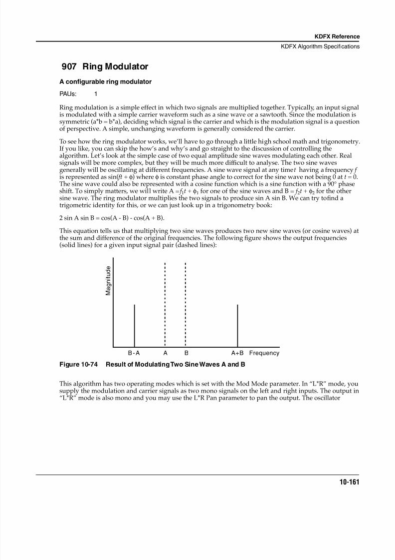
8/21/2019 MR_K2661
http://slidepdf.com/reader/full/mrk2661 243/499
KDFX Reference
KDFX Algorithm Specifications
10-161
907 Ring Modulator
A configurable ring modulator
PAUs: 1
Ring modulation is a simple effect in which two signals are multiplied together. Typically, an input signalis modulated with a simple carrier waveform such as a sine wave or a sawtooth. Since the modulation issymmetric (a*b = b*a), deciding which signal is the carrier and which is the modulation signal is a questionof perspective. A simple, unchanging waveform is generally considered the carrier.
To see how the ring modulator works, we’ll have to go through a little high school math and trigonometry.If you like, you can skip the how’s and why’s and go straight to the discussion of controlling thealgorithm. Let’s look at the simple case of two equal amplitude sine waves modulating each other. Realsignals will be more complex, but they will be much more dif ficult to analyse. The two sine wavesgenerally will be oscillating at different frequencies. A sine wave signal at any time t having a frequency f is represented as sin( ft + φ) where φ is constant phase angle to correct for the sine wave not being 0 at t = 0.The sine wave could also be represented with a cosine function which is a sine function with a 90° phaseshift. To simply matters, we will write A = f 1t + φ1 for one of the sine waves and B = f 2t + φ2 for the othersine wave. The ring modulator multiplies the two signals to produce sin A sin B. We can try to find atrigometric identity for this, or we can just look up in a trigonometry book:
2 sin A sin B = cos(A - B) - cos(A + B).
This equation tells us that multiplying two sine waves produces two new sine waves (or cosine waves) atthe sum and difference of the original frequencies. The following figure shows the output frequencies(solid lines) for a given input signal pair (dashed lines):
Figure 10-74 Result of Modulating Two Sine Waves A and B
This algorithm has two operating modes which is set with the Mod Mode parameter. In “L*R” mode, you
supply the modulation and carrier signals as two mono signals on the left and right inputs. The output in“L*R” mode is also mono and you may use the L*R Pan parameter to pan the output. The oscillator
Frequency
M
a g n i t u d e
A B A+BB-A
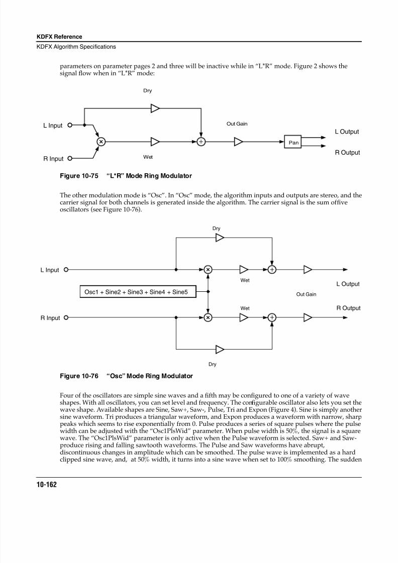
8/21/2019 MR_K2661
http://slidepdf.com/reader/full/mrk2661 244/499
10-162
KDFX Reference
KDFX Algorithm Specifications
parameters on parameter pages 2 and three will be inactive while in “L*R” mode. Figure 2 shows thesignal flow when in “L*R” mode:
Figure 10-75 “L*R” Mode Ring Modulator
The other modulation mode is “Osc”. In “Osc” mode, the algorithm inputs and outputs are stereo, and thecarrier signal for both channels is generated inside the algorithm. The carrier signal is the sum of fiveoscillators (see Figure 10-76).
Figure 10-76 “Osc” Mode Ring Modulator
Four of the oscillators are simple sine waves and a fifth may be configured to one of a variety of waveshapes. With all oscillators, you can set level and frequency. The configurable oscillator also lets you set thewave shape. Available shapes are Sine, Saw+, Saw-, Pulse, Tri and Expon (Figure 4). Sine is simply anothersine waveform. Tri produces a triangular waveform, and Expon produces a waveform with narrow, sharppeaks which seems to rise exponentially from 0. Pulse produces a series of square pulses where the pulsewidth can be adjusted with the “Osc1PlsWid” parameter. When pulse width is 50%, the signal is a squarewave. The “Osc1PlsWid” parameter is only active when the Pulse waveform is selected. Saw+ and Saw-produce rising and falling sawtooth waveforms. The Pulse and Saw waveforms have abrupt,discontinuous changes in amplitude which can be smoothed. The pulse wave is implemented as a hardclipped sine wave, and, at 50% width, it turns into a sine wave when set to 100% smoothing. The sudden
Pan
L Input
R Input
Dry
Wet
Out Gain
L Output
R Output
Osc1 + Sine2 + Sine3 + Sine4 + Sine5
L Input
R Input
Dry
Dry
Wet
Wet
L Output
R Output
Out Gain
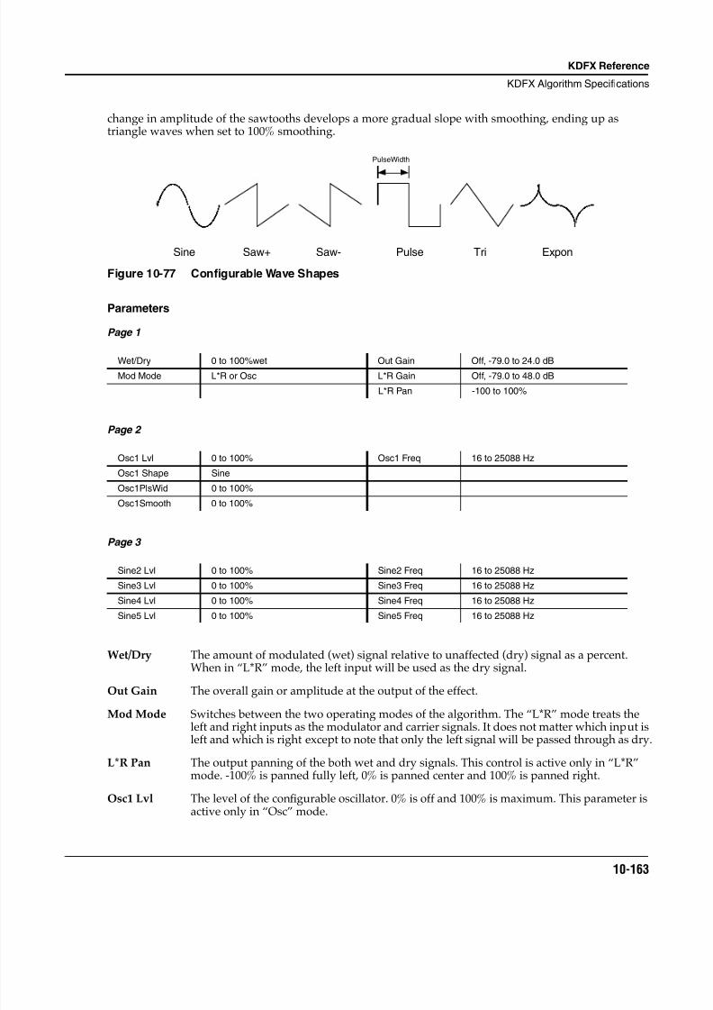
8/21/2019 MR_K2661
http://slidepdf.com/reader/full/mrk2661 245/499
KDFX Reference
KDFX Algorithm Specifications
10-163
change in amplitude of the sawtooths develops a more gradual slope with smoothing, ending up astriangle waves when set to 100% smoothing.
Figure 10-77 Configurable Wave Shapes
Parameters
Page 1
Page 2
Page 3
Wet/Dry The amount of modulated (wet) signal relative to unaffected (dry) signal as a percent.When in “L*R” mode, the left input will be used as the dry signal.
Out Gain The overall gain or amplitude at the output of the effect.
Mod Mode Switches between the two operating modes of the algorithm. The “L*R” mode treats theleft and right inputs as the modulator and carrier signals. It does not matter which input isleft and which is right except to note that only the left signal will be passed through as dry.
L*R Pan The output panning of the both wet and dry signals. This control is active only in “L*R”mode. -100% is panned fully left, 0% is panned center and 100% is panned right.
Osc1 Lvl The level of the configurable oscillator. 0% is off and 100% is maximum. This parameter isactive only in “Osc” mode.
Wet/Dry 0 to 100%wet Out Gain Off, -79.0 to 24.0 dB
Mod Mode L*R or Osc L*R Gain Off, -79.0 to 48.0 dB
L*R Pan -100 to 100%
Osc1 Lvl 0 to 100% Osc1 Freq 16 to 25088 Hz
Osc1 Shape Sine
Osc1PlsWid 0 to 100%
Osc1Smooth 0 to 100%
Sine2 Lvl 0 to 100% Sine2 Freq 16 to 25088 Hz
Sine3 Lvl 0 to 100% Sine3 Freq 16 to 25088 Hz
Sine4 Lvl 0 to 100% Sine4 Freq 16 to 25088 Hz
Sine5 Lvl 0 to 100% Sine5 Freq 16 to 25088 Hz
Sine Saw+ Saw- Pulse Tri Expon
PulseWidth
8/21/2019 MR_K2661
http://slidepdf.com/reader/full/mrk2661 246/499
10-164
KDFX Reference
KDFX Algorithm Specifications
Osc1 Freq The fundamental frequency of the configurable oscillator. The oscillators can be setthrough the audible frequencies 16-25088 Hz with 1 semitone resolution. This parameteris active only in “Osc” mode.
Osc1Shape Shape selects the waveform type for the configurable oscillator. Choices are Sine, Saw+,Saw-, Pulse, Tri, and Expon. This parameter is active only in “Osc” mode.
Osc1PlsWid When the configurable oscillator is set to Pulse, the PlsWid parameter sets the pulse widthas a percentage of the waveform period. The pulse is a square wave when the width is setto 50%. This parameter is active only in “Osc” mode and when the Pulse waveform isselected.
Osc1Smooth Smooths the Saw+, Saw-, and Pulse waveforms. For the sawtooth waves, smoothingmakes the waveform more like a triangle wave. For the Pulse wave, smoothing makes thewaveform more like a sine wave.
Sinen Lvl The four sine wave oscillators (n = 2...5) may have their levels set between 0% (off) and100% (maximum). This parameter is active only in “Osc” mode.
Sinen Freq The four sine wave oscillators (n = 2...5) may have their frequencies set with thisparameter. The oscillators can be set through the audible frequencies 16-25088 Hz with 1semitone resolution. This parameter is active only in “Osc” mode.
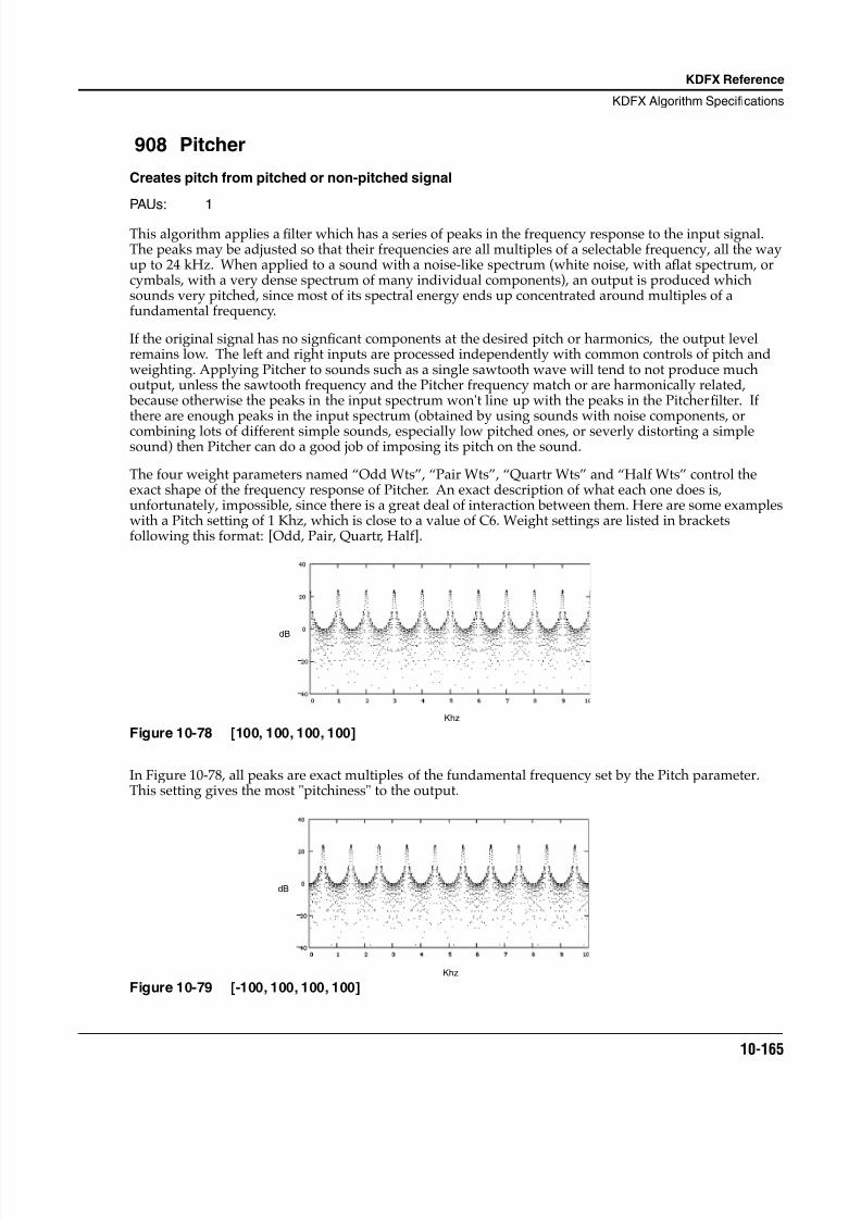
8/21/2019 MR_K2661
http://slidepdf.com/reader/full/mrk2661 247/499
KDFX Reference
KDFX Algorithm Specifications
10-165
908 Pitcher
Creates pitch from pitched or non-pitched signal
PAUs: 1
This algorithm applies a filter which has a series of peaks in the frequency response to the input signal.The peaks may be adjusted so that their frequencies are all multiples of a selectable frequency, all the wayup to 24 kHz. When applied to a sound with a noise-like spectrum (white noise, with a flat spectrum, orcymbals, with a very dense spectrum of many individual components), an output is produced whichsounds very pitched, since most of its spectral energy ends up concentrated around multiples of afundamental frequency.
If the original signal has no signficant components at the desired pitch or harmonics, the output levelremains low. The left and right inputs are processed independently with common controls of pitch andweighting. Applying Pitcher to sounds such as a single sawtooth wave will tend to not produce muchoutput, unless the sawtooth frequency and the Pitcher frequency match or are harmonically related, because otherwise the peaks in the input spectrum won't line up with the peaks in the Pitcher filter. Ifthere are enough peaks in the input spectrum (obtained by using sounds with noise components, orcombining lots of different simple sounds, especially low pitched ones, or severly distorting a simplesound) then Pitcher can do a good job of imposing its pitch on the sound.
The four weight parameters named “Odd Wts”, “Pair Wts”, “Quartr Wts” and “Half Wts” control theexact shape of the frequency response of Pitcher. An exact description of what each one does is,unfortunately, impossible, since there is a great deal of interaction between them. Here are some exampleswith a Pitch setting of 1 Khz, which is close to a value of C6. Weight settings are listed in bracketsfollowing this format: [Odd, Pair, Quartr, Half].
Figure 10-78 [100, 100, 100, 100]
In Figure 10-78 , all peaks are exact multiples of the fundamental frequency set by the Pitch parameter.This setting gives the most "pitchiness" to the output.
Figure 10-79 [-100, 100, 100, 100]
Khz
dB
dB
Khz
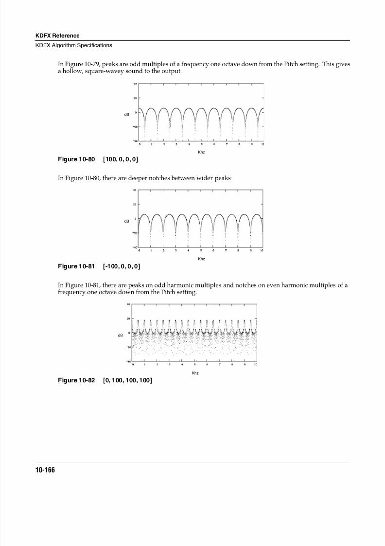
8/21/2019 MR_K2661
http://slidepdf.com/reader/full/mrk2661 248/499
10-166
KDFX Reference
KDFX Algorithm Specifications
In Figure 10-79, peaks are odd multiples of a frequency one octave down from the Pitch setting. This givesa hollow, square-wavey sound to the output.
Figure 10-80 [100, 0, 0, 0]
In Figure 10-80 , there are deeper notches between wider peaks
Figure 10-81 [-100, 0, 0, 0]
In Figure 10-81 , there are peaks on odd harmonic multiples and notches on even harmonic multiples of afrequency one octave down from the Pitch setting.
Figure 10-82 [0, 100, 100, 100]
Khz
dB
Khz
dB
Khz
dB
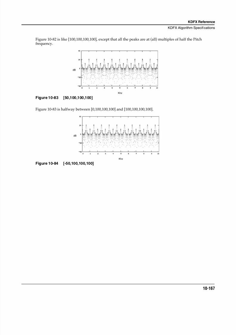
8/21/2019 MR_K2661
http://slidepdf.com/reader/full/mrk2661 249/499
KDFX Reference
KDFX Algorithm Specifications
10-167
Figure 10-82 is like [100,100,100,100], except that all the peaks are at (all) multiples of half the Pitchfrequency.
Figure 10-83 [50,100,100,100]
Figure 10-83 is halfway between [0,100,100,100] and [100,100,100,100].
Figure 10-84 [-50,100,100,100]
Khz
dB
Khz
dB
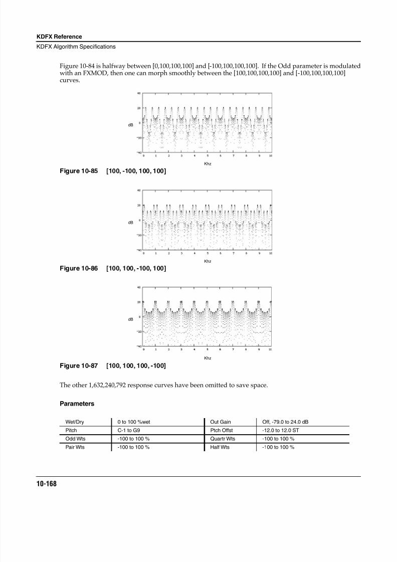
8/21/2019 MR_K2661
http://slidepdf.com/reader/full/mrk2661 250/499
10-168
KDFX Reference
KDFX Algorithm Specifications
Figure 10-84 is halfway between [0,100,100,100] and [-100,100,100,100]. If the Odd parameter is modulatedwith an FXMOD, then one can morph smoothly between the [100,100,100,100] and [-100,100,100,100]curves.
Figure 10-85 [100, -100, 100, 100]
Figure 10-86 [100, 100, -100, 100]
Figure 10-87 [100, 100, 100, -100]
The other 1,632,240,792 response curves have been omitted to save space.
Parameters
Wet/Dry 0 to 100 %wet Out Gain Off, -79.0 to 24.0 dB
Pitch C-1 to G9 Ptch Offst -12.0 to 12.0 ST
Odd Wts -100 to 100 % Quartr Wts -100 to 100 %
Pair Wts -100 to 100 % Half Wts -100 to 100 %
Khz
dB
Khz
dB
Khz
dB
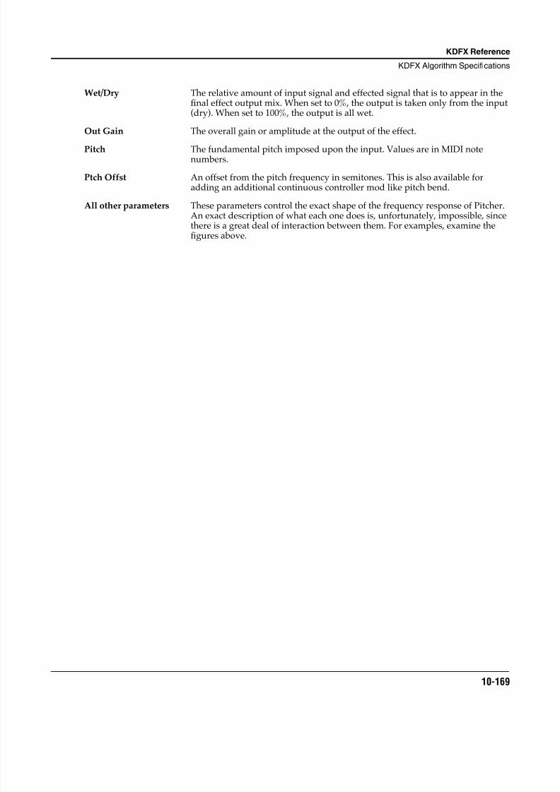
8/21/2019 MR_K2661
http://slidepdf.com/reader/full/mrk2661 251/499
KDFX Reference
KDFX Algorithm Specifications
10-169
Wet/Dry The relative amount of input signal and effected signal that is to appear in thefinal effect output mix. When set to 0%, the output is taken only from the input(dry). When set to 100%, the output is all wet.
Out Gain The overall gain or amplitude at the output of the effect.
Pitch The fundamental pitch imposed upon the input. Values are in MIDI notenumbers.
Ptch Offst An offset from the pitch frequency in semitones. This is also available foradding an additional continuous controller mod like pitch bend.
All other parameters These parameters control the exact shape of the frequency response of Pitcher.An exact description of what each one does is, unfortunately, impossible, sincethere is a great deal of interaction between them. For examples, examine thefigures above.
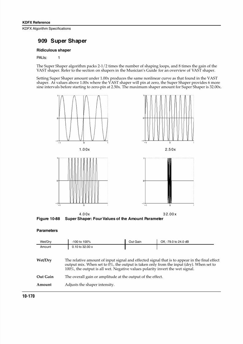
8/21/2019 MR_K2661
http://slidepdf.com/reader/full/mrk2661 252/499
10-170
KDFX Reference
KDFX Algorithm Specifications
909 Super Shaper
Ridiculous shaper
PAUs: 1
The Super Shaper algorithm packs 2-1/2 times the number of shaping loops, and 8 times the gain of theVAST shaper. Refer to the section on shapers in the Musician’s Guide for an overview of VAST shaper.
Setting Super Shaper amount under 1.00x produces the same nonlinear curve as that found in the VASTshaper. At values above 1.00x where the VAST shaper will pin at zero, the Super Shaper provides 6 moresine intervals before starting to zero-pin at 2.50x. The maximum shaper amount for Super Shaper is 32.00x.
Figure 10-88 Super Shaper: Four Values of the Amount Parameter
Parameters
Wet/Dry The relative amount of input signal and effected signal that is to appear in the final effectoutput mix. When set to 0%, the output is taken only from the input (dry). When set to100%, the output is all wet. Negative values polarity invert the wet signal.
Out Gain The overall gain or amplitude at the output of the effect.
Amount Adjusts the shaper intensity.
Wet/Dry -100 to 100% Out Gain Off, -79.0 to 24.0 dB
Amount 0.10 to 32.00 x
1.0 0x 2.5 0x
4.0 0x 3 2.00 x
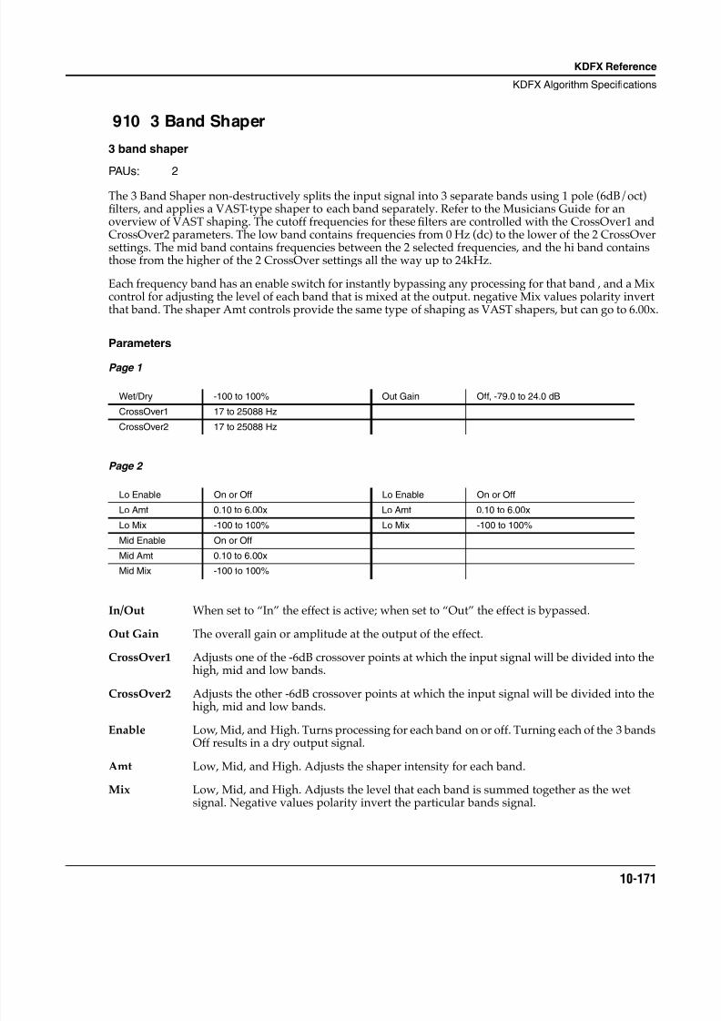
8/21/2019 MR_K2661
http://slidepdf.com/reader/full/mrk2661 253/499
KDFX Reference
KDFX Algorithm Specifications
10-171
910 3 Band Shaper
3 band shaper
PAUs: 2
The 3 Band Shaper non-destructively splits the input signal into 3 separate bands using 1 pole (6dB/oct)filters, and applies a VAST-type shaper to each band separately. Refer to the Musicians Guide for anoverview of VAST shaping. The cutoff frequencies for these filters are controlled with the CrossOver1 andCrossOver2 parameters. The low band contains frequencies from 0 Hz (dc) to the lower of the 2 CrossOversettings. The mid band contains frequencies between the 2 selected frequencies, and the hi band containsthose from the higher of the 2 CrossOver settings all the way up to 24kHz.
Each frequency band has an enable switch for instantly bypassing any processing for that band , and a Mixcontrol for adjusting the level of each band that is mixed at the output. negative Mix values polarity invertthat band. The shaper Amt controls provide the same type of shaping as VAST shapers, but can go to 6.00x.
Parameters
Page 1
Page 2
In/Out When set to “In” the effect is active; when set to “Out” the effect is bypassed.
Out Gain The overall gain or amplitude at the output of the effect.
CrossOver1 Adjusts one of the -6dB crossover points at which the input signal will be divided into thehigh, mid and low bands.
CrossOver2 Adjusts the other -6dB crossover points at which the input signal will be divided into thehigh, mid and low bands.
Enable Low, Mid, and High. Turns processing for each band on or off. Turning each of the 3 bandsOff results in a dry output signal.
Amt Low, Mid, and High. Adjusts the shaper intensity for each band.
Mix Low, Mid, and High. Adjusts the level that each band is summed together as the wetsignal. Negative values polarity invert the particular bands signal.
Wet/Dry -100 to 100% Out Gain Off, -79.0 to 24.0 dB
CrossOver1 17 to 25088 Hz
CrossOver2 17 to 25088 Hz
Lo Enable On or Off Lo Enable On or Off
Lo Amt 0.10 to 6.00x Lo Amt 0.10 to 6.00x
Lo Mix -100 to 100% Lo Mix -100 to 100%
Mid Enable On or Off
Mid Amt 0.10 to 6.00x
Mid Mix -100 to 100%
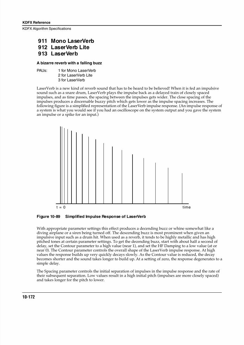
8/21/2019 MR_K2661
http://slidepdf.com/reader/full/mrk2661 254/499
10-172
KDFX Reference
KDFX Algorithm Specifications
911 Mono LaserVerb912 LaserVerb Lite913 LaserVerb
A bizarre reverb with a falling buzz
PAUs: 1 for Mono LaserVerb2 for LaserVerb Lite
3 for LaserVerb
LaserVerb is a new kind of reverb sound that has to be heard to be believed! When it is fed an impulsivesound such as a snare drum, LaserVerb plays the impulse back as a delayed train of closely spacedimpulses, and as time passes, the spacing between the impulses gets wider. The close spacing of theimpulses produces a discernable buzzy pitch which gets lower as the impulse spacing increases. Thefollowing figure is a simplified representation of the LaserVerb impulse response. (An impulse response ofa system is what you would see if you had an oscilloscope on the system output and you gave the systeman impulse or a spike for an input.)
Figure 10-89 Simplified Impulse Response of LaserVerb
With appropriate parameter settings this effect produces a decending buzz or whine somewhat like adiving airplane or a siren being turned off. The descending buzz is most prominent when given animpulsive input such as a drum hit. When used as a reverb, it tends to be highly metallic and has high
pitched tones at certain parameter settings. To get the decending buzz, start with about half a second ofdelay, set the Contour parameter to a high value (near 1), and set the HF Damping to a low value (at ornear 0). The Contour parameter controls the overall shape of the LaserVerb impulse response. At highvalues the response builds up very quickly decays slowly. As the Contour value is reduced, the decay becomes shorter and the sound takes longer to build up. At a setting of zero, the response degenerates to asimple delay.
The Spacing parameter controls the initial separation of impulses in the impulse response and the rate oftheir subsequent separation. Low values result in a high initial pitch (impulses are more closely spaced)and takes longer for the pitch to lower.
t = 0 time
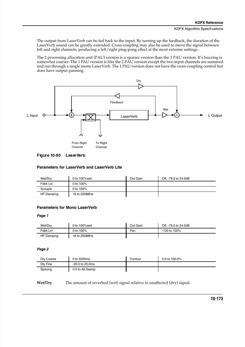
8/21/2019 MR_K2661
http://slidepdf.com/reader/full/mrk2661 255/499
KDFX Reference
KDFX Algorithm Specifications
10-173
The output from LaserVerb can be fed back to the input. By turning up the feedback, the duration of theLaserVerb sound can be greatly extended. Cross-coupling may also be used to move the signal betweenleft and right channels, producing a left/right ping-pong effect at the most extreme settings.
The 2 processing allocation unit (PAU) version is a sparser version than the 3 PAU version. It’s buzzing issomewhat coarser. The 1 PAU version is like the 2 PAU version except the two input channels are summedand run through a single mono LaserVerb. The 1 PAU version does not have the cross-coupling control butdoes have output panning.
Figure 10-90 LaserVerb
Parameters for LaserVerb and LaserVerb Lite
Parameters for Mono LaserVerb
Page 1
Page 2
Wet/Dry The amount of reverbed (wet) signal relative to unaffected (dry) signal.
Wet/Dry 0 to 100%wet Out Gain Off, -79.0 to 24.0dB
Fdbk Lvl 0 to 100%
Xcouple 0 to 100%
HF Damping 16 to 25088Hz
Wet/Dry 0 to 100%wet Out Gain Off, -79.0 to 24.0dB
Fdbk Lvl 0 to 100% Pan -100 to 100%
HF Damping 16 to 25088Hz
Dly Coarse 0 to 5000ms Contour 0.0 to 100.0%
Dly Fine -20.0 to 20.0ms
Spacing 0.0 to 40.0samp
LaserVerb
From Right
Channel
To Right
Channel
Dry
Feedback
Wet
L OutputL Input
8/21/2019 MR_K2661
http://slidepdf.com/reader/full/mrk2661 256/499
10-174
KDFX Reference
KDFX Algorithm Specifications
Out Gain The overall gain or amplitude at the output of the effect.
Fdbk Lvl The percentage of the reverb output to feed back or return to the reverb input. Turning upthe feedback is a way to stretch out the duration of the reverb, or, if the reverb is set to behave as a delay, to repeat the delay. The higher feedback is set, the longer the decay orecho will last.
Xcouple LaserVerb & LaserVerb Lite are stereo effects. The cross-coupling control lets you send thesum of the input and feedback from one channel to its own LaserVerb effect (0% crosscoupling) or to the other channel’s effect (100% cross coupling) or somewhere in between.This control is not available in Mono LaserVerb.
HF Damping The damping of high frequencies relative to low frequencies. When set to the highestfrequency (25088 Hz), there is no damping and all frequencies decay at the same rate. Atlower frequency settings, high frequency signal components will decay faster than lowfrequency components. If set too low, everything will decay almost immediately.
Pan The Pan control is available in the Mono LaserVerb. The left and right inputs get summedto mono, the mono signal passes through the LaserVerb, and the final mono output is
panned to the left and right outputs. Panning ranges from -100% (fully left), through 0%(centered), through to 100% (fully right).
Dly Coarse You can set the overall delay length from 0 to 2 seconds (3 PAU) or 0 to 1.3 seconds (2PAU). Lengthening the delay will increase the duration or decay time of the reverb. Toreduce LaserVerb to a simple delay, set the Contour and Feedback controls to 0. Use adelay of about half a second as a starting point.
Dly Fine The delay fine adjust is added to the delay coarse adjust to provide a delay resolutiondown to 0.1 ms.
Spacing Determines the starting pitch of the decending buzz and how fast it decends. The Spacingparameter sets the initial separation of impulses in the impulse response and subsequentrate of increasing impulse separation. The spacing between impulses is given in samplesand may be a fraction of a sample. (A sample is the time between successive digital wordswhich is 20.8 µs or 1/48000 seconds.) For low values, the buzz starts at high frequenciesand drops slowly. At high values the buzz starts at a lower pitch and drops rapidly.
Contour Controls the overall envelope shape of the reverb. When set to a high value, soundspassed through the reverb start at a high level and slowly decay. As the control value isreduced, it takes some time for the effect to build up before decaying. At a value of around34, the reverb is behaving like a reverse reverb, building up to a hit. When the Contour isset to zero, LaserVerb is reduced to a simple delay.
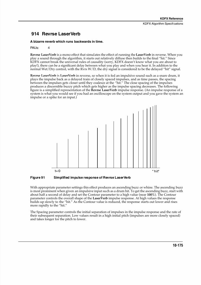
8/21/2019 MR_K2661
http://slidepdf.com/reader/full/mrk2661 257/499
KDFX Reference
KDFX Algorithm Specifications
10-175
914 Revrse LaserVerb
A bizarre reverb which runs backwards in time.
PAUs: 4
Revrse LaserVerb is a mono effect that simulates the effect of running the LaserVerb in reverse. When youplay a sound through the algorithm, it starts out relatively diffuse then builds to the final “hit.” SinceKDFX cannot break the universal rules of causality (sorry, KDFX doesn’t know what you are about toplay!), there can be a significant delay between what you play and when you hear it. In addition to thenormal Wet/Dry control, with the Rvrs W/D, the dry signal is considered to be the delayed “hit” signal.
Revrse LaserVerb is LaserVerb in reverse, so when it is fed an impulsive sound such as a snare drum, itplays the impulse back as a delayed train of closely spaced impulses, and as time passes, the spacing between the impulses gets closer until they coalesce at the “hit.” The close spacing of the impulsesproduces a discernible buzzy pitch which gets higher as the impulse spacing decreases. The followingfigure is a simplified representation of the Revrse LaserVerb impulse response. (An impulse response of asystem is what you would see if you had an oscilloscope on the system output and you gave the system animpulse or a spike for an input.)
Figure 91 Simplified impulse response of Revrse LaserVerb
With appropriate parameter settings this effect produces an ascending buzz or whine. The ascending buzzis most prominent when given an impulsive input such as a drum hit. To get the ascending buzz, start withabout half a second of delay and set the Contour parameter to a high value (near 100%). The Contour
parameter controls the overall shape of the LaserVerb impulse response. At high values the response builds up slowly to the “hit.” As the Contour value is reduced, the response starts out lower and risesmore rapidly to the “hit.”
The Spacing parameter controls the initial separation of impulses in the impulse response and the rate oftheir subsequent separation. Low values result in a high initial pitch (impulses are more closely spaced)and takes longer for the pitch to lower.
t=0 " hit"
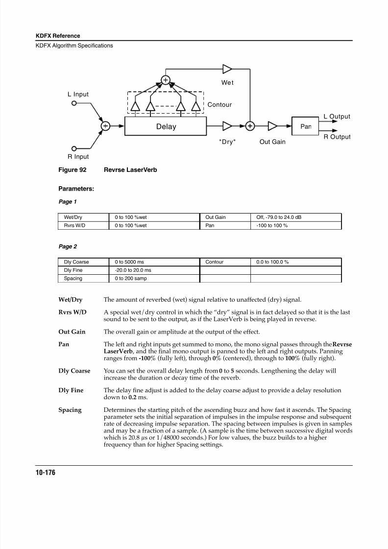
8/21/2019 MR_K2661
http://slidepdf.com/reader/full/mrk2661 258/499
10-176
KDFX Reference
KDFX Algorithm Specifications
Figure 92 Revrse LaserVerb
Parameters:
Page 1
Page 2
Wet/Dry The amount of reverbed (wet) signal relative to unaffected (dry) signal.
Rvrs W/D A special wet/dry control in which the “dry” signal is in fact delayed so that it is the lastsound to be sent to the output, as if the LaserVerb is being played in reverse.
Out Gain The overall gain or amplitude at the output of the effect.
Pan The left and right inputs get summed to mono, the mono signal passes through the RevrseLaserVerb , and the final mono output is panned to the left and right outputs. Panningranges from -100% (fully left), through 0% (centered), through to 100% (fully right).
Dly Coarse You can set the overall delay length from 0 to 5 seconds. Lengthening the delay willincrease the duration or decay time of the reverb.
Dly Fine The delay fine adjust is added to the delay coarse adjust to provide a delay resolutiondown to 0.2 ms.
Spacing Determines the starting pitch of the ascending buzz and how fast it ascends. The Spacingparameter sets the initial separation of impulses in the impulse response and subsequentrate of decreasing impulse separation. The spacing between impulses is given in samplesand may be a fraction of a sample. (A sample is the time between successive digital wordswhich is 20.8 µs or 1/48000 seconds.) For low values, the buzz builds to a higherfrequency than for higher Spacing settings.
Wet/Dry 0 to 100 %wet Out Gain Off, -79.0 to 24.0 dB
Rvrs W/D 0 to 100 %wet Pan -100 to 100 %
Dly Coarse 0 to 5000 ms Contour 0.0 to 100.0 %
Dly Fine -20.0 to 20.0 ms
Spacing 0 to 200 samp
L Input
R Input
Delay Pan
"Dry"
Wet
Out Gain
Contour
L Output
R Output
8/21/2019 MR_K2661
http://slidepdf.com/reader/full/mrk2661 259/499
KDFX Reference
KDFX Algorithm Specifications
10-177
Contour Controls the overall envelope shape of the reverb. When set to a high value, sounds startat a high level and build slowly to the final “hit.” As the control value is reduced, soundsstart lower and build rapidly to the final “hit.”
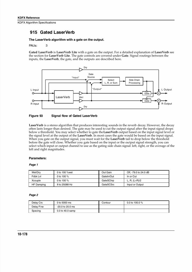
8/21/2019 MR_K2661
http://slidepdf.com/reader/full/mrk2661 260/499
10-178
KDFX Reference
KDFX Algorithm Specifications
915 Gated LaserVerb
The LaserVerb algorithm with a gate on the output.
PAUs: 3
Gated LaserVerb is LaserVerb Lite with a gate on the output. For a detailed explanation of LaserVerb seethe section for LaserVerb Lite. The gate controls are covered under Gate. Signal routings between theinputs, the LaserVerb , the gate, and the outputs are described here.
Figure 93 Signal flow of Gated LaserVerb
LaserVerb is a stereo algorithm that produces interesting sounds in the reverb decay. However, the decayoften lasts longer than desired. The gate may be used to cut the output signal after the input signal drops below a threshold. You may select whether to gate the LaserVerb output based on the input signal level orthe signal level at the output of the LaserVerb. In most cases the gate would be based on the input signal.When you gate on the output signal, you must wait for the LaserVerb tail to drop below the threshold
before the gate will close. Whether you gate based on the input or the output signal strength, you canselect which input or output channel to use as the gating side chain signal: left, right, or the average of theleft and right magnitudes.
Parameters:
Page 1
Page 2
Wet/Dry 0 to 100 %wet Out Gain Off, -79.0 to 24.0 dB
Fdbk Lvl 0 to 100 % GateIn/Out In or Out
Xcouple 0 to 100 % GateSCInp L, R, (L+R)/2
HF Damping 8 to 25088 Hz GateSCSrc Input or Output
Delay Crs 0 to 5000 ms Contour 0.0 to 100.0 %
Delay Fine -20.0 to 20.0 ms
Spacing 0.0 to 40.0 samp
Select
L, R, or Sum
L Input
R Input
LaserVerb Wet
"Input"
"Output"
Gate
Source
Side Chain
Processing
Gate
Gate
L Output
R Output
Dry
Dry
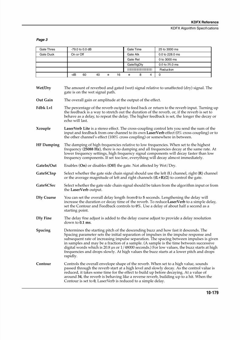
8/21/2019 MR_K2661
http://slidepdf.com/reader/full/mrk2661 261/499
KDFX Reference
KDFX Algorithm Specifications
10-179
Page 3
Wet/Dry The amount of reverbed and gated (wet) signal relative to unaffected (dry) signal. Thegate is on the wet signal path.
Out Gain The overall gain or amplitude at the output of the effect.
Fdbk Lvl The percentage of the reverb output to feed back or return to the reverb input. Turning upthe feedback is a way to stretch out the duration of the reverb, or, if the reverb is set to behave as a delay, to repeat the delay. The higher feedback is set, the longer the decay orecho will last.
Xcouple LaserVerb Lite is a stereo effect. The cross-coupling control lets you send the sum of theinput and feedback from one channel to its own LaserVerb effect (0% cross coupling) or tothe other channel’s effect (100% cross coupling) or somewhere in between.
HF Damping The damping of high frequencies relative to low frequencies. When set to the highestfrequency (25088 Hz), there is no damping and all frequencies decay at the same rate. Atlower frequency settings, high frequency signal components will decay faster than lowfrequency components. If set too low, everything will decay almost immediately.
GateIn/Out Enables (On) or disables (Off) the gate. Not affected by Wet/Dry.
GateSCInp Select whether the gate side chain signal should use the left (L) channel, right (R) channel
or the average magnitude of left and right channels ((L+R)/2) to control the gate.GateSCSrc Select whether the gate side chain signal should be taken from the algorithm input or from
the LaserVerb output.
Dly Coarse You can set the overall delay length from 0 to 5 seconds. Lengthening the delay willincrease the duration or decay time of the reverb. To reduce LaserVerb to a simple delay,set the Contour and Feedback controls to 0%. Use a delay of about half a second as astarting point.
Dly Fine The delay fine adjust is added to the delay coarse adjust to provide a delay resolutiondown to 0.1 ms.
Spacing Determines the starting pitch of the descending buzz and how fast it descends. TheSpacing parameter sets the initial separation of impulses in the impulse response and
subsequent rate of increasing impulse separation. The spacing between impulses is givenin samples and may be a fraction of a sample. (A sample is the time between successivedigital words which is 20.8 µs or 1/48000 seconds.) For low values, the buzz starts at highfrequencies and drops slowly. At high values the buzz starts at a lower pitch and dropsrapidly.
Contour Controls the overall envelope shape of the reverb. When set to a high value, soundspassed through the reverb start at a high level and slowly decay. As the control value isreduced, it takes some time for the effect to build up before decaying. At a value ofaround 34 , the reverb is behaving like a reverse reverb, building up to a hit. When theContour is set to 0 , LaserVerb is reduced to a simple delay.
Gate Thres -79.0 to 0.0 dB Gate Time 25 to 3000 ms
Gate Duck On or Off Gate Atk 0.0 to 228.0 ms
Gate Rel 0 to 3000 msGateSigDly 0.0 to 25.0 ms
|||||||||||||||||||||||||||||| Reduction
-dB 60 40 16 8 4 0
8/21/2019 MR_K2661
http://slidepdf.com/reader/full/mrk2661 262/499
10-180
KDFX Reference
KDFX Algorithm Specifications
Gate Thresh The signal level in dB required to open the gate (or close the gate if Ducking is on).
Gate Duck When set to Off , the gate opens when the signal rises above threshold and closes whenthe gate time expires. When set to On , the gate closes when the signal rises abovethreshold and opens when the gate time expires.
Gate Time The time in seconds that the gate will stay fully on after the signal envelope rises abovethreshold. The gate timer is started or restarted whenever the signal envelope rises abovethreshold.
Gate Atk The time for the gate to ramp from closed to open (reverse if Ducking is on) after thesignal rises above threshold.
Gate Rel The time for the gate to ramp from open to closed (reverse if Ducking is on) after the gatetimer has elapsed.
GateSigDly The delay in milliseconds (ms) of the signal to be gated relative to the side chain signal. Bydelaying the main signal, the gate can be opened before the main signal rises above thegating threshold.
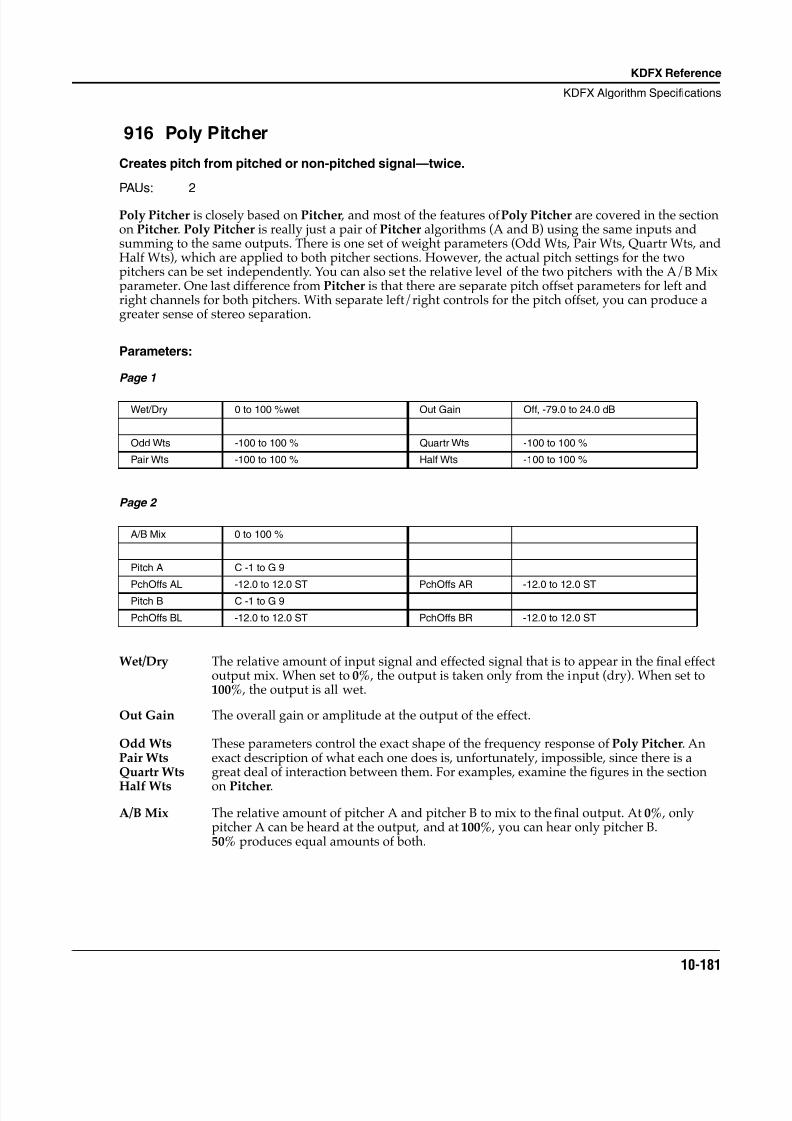
8/21/2019 MR_K2661
http://slidepdf.com/reader/full/mrk2661 263/499
KDFX Reference
KDFX Algorithm Specifications
10-181
916 Poly Pitcher
Creates pitch from pitched or non-pitched signal—twice.
PAUs: 2
Poly Pitcher is closely based on Pitcher , and most of the features of Poly Pitcher are covered in the sectionon Pitcher. Poly Pitcher is really just a pair of Pitcher algorithms (A and B) using the same inputs andsumming to the same outputs. There is one set of weight parameters (Odd Wts, Pair Wts, Quartr Wts, andHalf Wts), which are applied to both pitcher sections. However, the actual pitch settings for the twopitchers can be set independently. You can also set the relative level of the two pitchers with the A/B Mixparameter. One last difference from Pitcher is that there are separate pitch offset parameters for left andright channels for both pitchers. With separate left/right controls for the pitch offset, you can produce agreater sense of stereo separation.
Parameters:
Page 1
Page 2
Wet/Dry The relative amount of input signal and effected signal that is to appear in the final effectoutput mix. When set to 0% , the output is taken only from the input (dry). When set to100% , the output is all wet.
Out Gain The overall gain or amplitude at the output of the effect.
A/B Mix The relative amount of pitcher A and pitcher B to mix to the final output. At 0% , onlypitcher A can be heard at the output, and at 100% , you can hear only pitcher B.50% produces equal amounts of both.
Wet/Dry 0 to 100 %wet Out Gain Off, -79.0 to 24.0 dB
Odd Wts -100 to 100 % Quartr Wts -100 to 100 %
Pair Wts -100 to 100 % Half Wts -100 to 100 %
A/B Mix 0 to 100 %
Pitch A C -1 to G 9
PchOffs AL -12.0 to 12.0 ST PchOffs AR -12.0 to 12.0 STPitch B C -1 to G 9
PchOffs BL -12.0 to 12.0 ST PchOffs BR -12.0 to 12.0 ST
Odd WtsPair WtsQuartr Wts
Half Wts
These parameters control the exact shape of the frequency response of Poly Pitcher. Anexact description of what each one does is, unfortunately, impossible, since there is agreat deal of interaction between them. For examples, examine the figures in the section
on Pitcher.
8/21/2019 MR_K2661
http://slidepdf.com/reader/full/mrk2661 264/499
10-182
KDFX Reference
KDFX Algorithm Specifications
Pitch A, B The fundamental pitch imposed upon the input expressed in semitone scale intervals.Pitcher A and pitcher B may be set independently.
PchOff ALPchOff ARPchOff BLPchOff BR
An offset from the pitch frequency in semitones. Not only are the A and B pitcherstreated separately, the left and right channels have their own controls for increasedstereo separation. Pitch offset may be useful as a modifiable control resembling pitch bend.
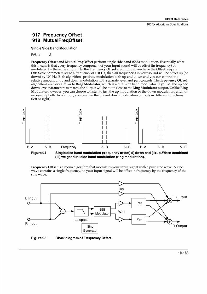
8/21/2019 MR_K2661
http://slidepdf.com/reader/full/mrk2661 265/499
KDFX Reference
KDFX Algorithm Specifications
10-183
917 Frequency Offset918 MutualFreqOffset
Single Side Band Modulation
PAUs: 2
Frequency Offset and MutualFreqOffset perform single side band (SSB) modulation. Essentially whatthis means is that every frequency component of your input sound will be offset (in frequency) ormodulated by the same amount. In the Frequency Offset algorithm, if you have the OffsetFreq andOffs Scale parameters set to a frequency of 100 Hz , then all frequencies in your sound will be offset up (ordown) by 100 Hz. Both algorithms produce modulation both up and down and you can control therelative amount of up and down modulation with separate level and pan controls. The Frequency Offset algorithms are very similar to Ring Modulator , which is a dual side band modulator. If you set the up anddown level parameters to match, the output will be quite close to the Ring Modulator output. Unlike RingModulator however, you can choose to listen to just the up modulation or the down modulation, and notnecessarily both. In addition, you can pan the up and down modulation outputs in different directions(left or right).
Figure 94 Single side band modulation (frequency offset) (i) down and (ii) up. When combined(iii) we get dual side band modulation (ring modulation).
Frequency Offset is a mono algorithm that modulates your input signal with a pure sine wave. A sinewave contains a single frequency, so your input signal will be offset in frequency by the frequency of thesine wave.
Figure 95 Block diagram of Frequency Offset
A BB- A A+ BFrequencyA BB- A A B A+ B
L Input
R InputLowpass
SSB
Modulator
Sine
Generator
Pan
Pan
Wet
Dry
L Output
R Output
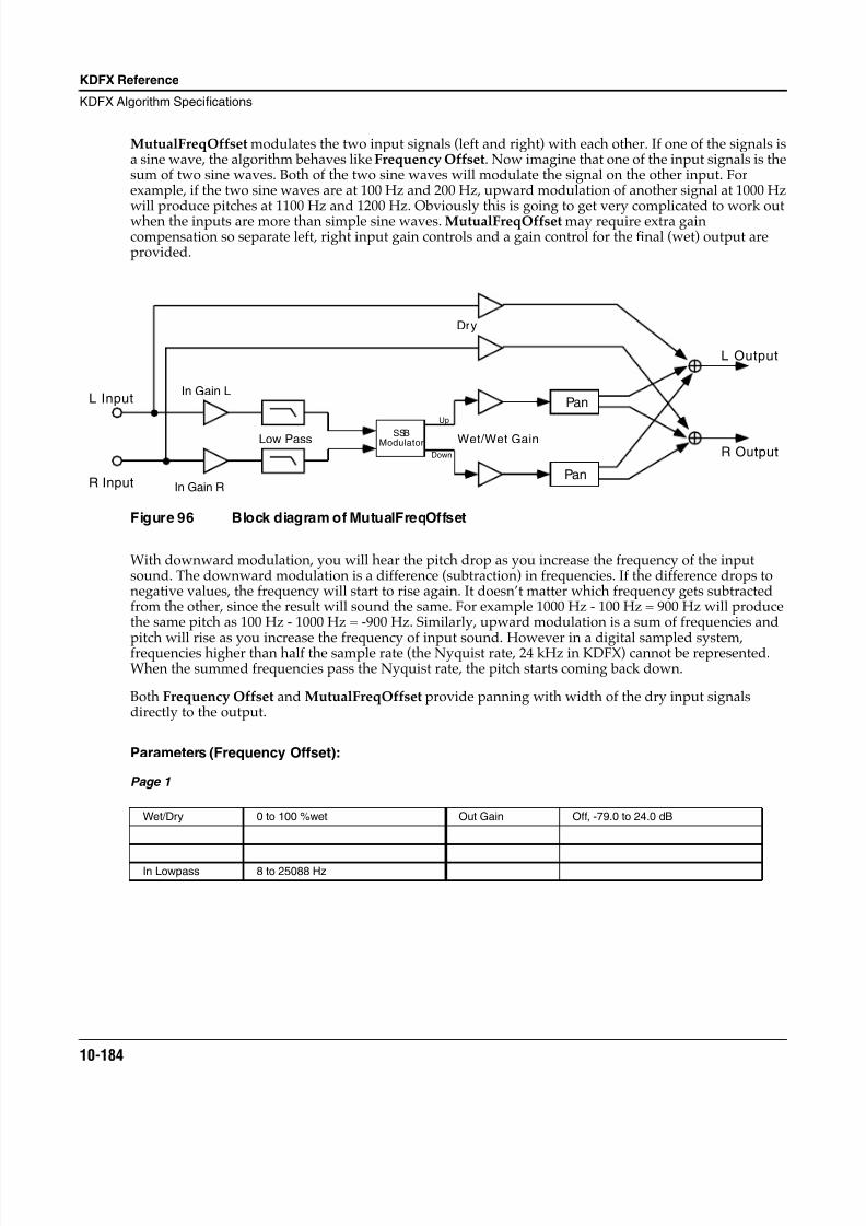
8/21/2019 MR_K2661
http://slidepdf.com/reader/full/mrk2661 266/499
10-184
KDFX Reference
KDFX Algorithm Specifications
MutualFreqOffset modulates the two input signals (left and right) with each other. If one of the signals isa sine wave, the algorithm behaves like Frequency Offset. Now imagine that one of the input signals is thesum of two sine waves. Both of the two sine waves will modulate the signal on the other input. Forexample, if the two sine waves are at 100 Hz and 200 Hz, upward modulation of another signal at 1000 Hzwill produce pitches at 1100 Hz and 1200 Hz. Obviously this is going to get very complicated to work outwhen the inputs are more than simple sine waves. MutualFreqOffset may require extra gaincompensation so separate left, right input gain controls and a gain control for the final (wet) output areprovided.
Figure 96 Block diagram of MutualFreqOffset
With downward modulation, you will hear the pitch drop as you increase the frequency of the inputsound. The downward modulation is a difference (subtraction) in frequencies. If the difference drops tonegative values, the frequency will start to rise again. It doesn’t matter which frequency gets subtractedfrom the other, since the result will sound the same. For example 1000 Hz - 100 Hz = 900 Hz will producethe same pitch as 100 Hz - 1000 Hz = -900 Hz. Similarly, upward modulation is a sum of frequencies and
pitch will rise as you increase the frequency of input sound. However in a digital sampled system,frequencies higher than half the sample rate (the Nyquist rate, 24 kHz in KDFX) cannot be represented.When the summed frequencies pass the Nyquist rate, the pitch starts coming back down.
Both Frequency Offset and MutualFreqOffset provide panning with width of the dry input signalsdirectly to the output.
Parameters (Frequency Offset):
Page 1
Wet/Dry 0 to 100 %wet Out Gain Off, -79.0 to 24.0 dB
In Lowpass 8 to 25088 Hz
SSBModulator
Pan
Pan
Dry
Wet/Wet Gain
Up
Down
In Gain L
In Gain R
L Input
R Input
L Output
R OutputLow Pass
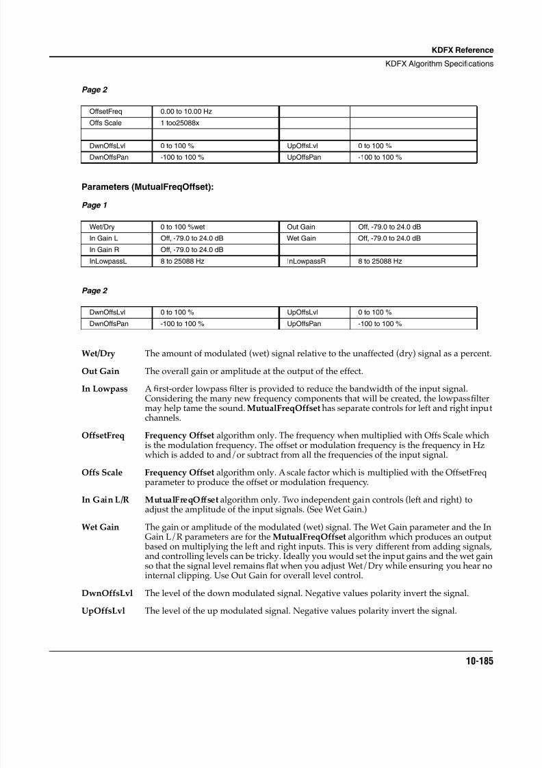
8/21/2019 MR_K2661
http://slidepdf.com/reader/full/mrk2661 267/499
KDFX Reference
KDFX Algorithm Specifications
10-185
Page 2
Parameters (MutualFreqOffset):
Page 1
Page 2
Wet/Dry The amount of modulated (wet) signal relative to the unaffected (dry) signal as a percent.
Out Gain The overall gain or amplitude at the output of the effect.
In Lowpass A first-order lowpass filter is provided to reduce the bandwidth of the input signal.Considering the many new frequency components that will be created, the lowpass filtermay help tame the sound. MutualFreqOffset has separate controls for left and right inputchannels.
OffsetFreq Frequency Offset algorithm only. The frequency when multiplied with Offs Scale whichis the modulation frequency. The offset or modulation frequency is the frequency in Hzwhich is added to and/or subtract from all the frequencies of the input signal.
Offs Scale Frequency Offset algorithm only. A scale factor which is multiplied with the OffsetFreqparameter to produce the offset or modulation frequency.
In Gain L/R MutualFreqOffset algorithm only. Two independent gain controls (left and right) toadjust the amplitude of the input signals. (See Wet Gain.)
Wet Gain The gain or amplitude of the modulated (wet) signal. The Wet Gain parameter and the In
Gain L/R parameters are for the MutualFreqOffset algorithm which produces an output based on multiplying the left and right inputs. This is very different from adding signals,and controlling levels can be tricky. Ideally you would set the input gains and the wet gainso that the signal level remains flat when you adjust Wet/Dry while ensuring you hear nointernal clipping. Use Out Gain for overall level control.
DwnOffsLvl The level of the down modulated signal. Negative values polarity invert the signal.
UpOffsLvl The level of the up modulated signal. Negative values polarity invert the signal.
OffsetFreq 0.00 to 10.00 Hz
Offs Scale 1 too25088x
DwnOffsLvl 0 to 100 % UpOffsLvl 0 to 100 %
DwnOffsPan -100 to 100 % UpOffsPan -100 to 100 %
Wet/Dry 0 to 100 %wet Out Gain Off, -79.0 to 24.0 dB
In Gain L Off, -79.0 to 24.0 dB Wet Gain Off, -79.0 to 24.0 dB
In Gain R Off, -79.0 to 24.0 dB
InLowpassL 8 to 25088 Hz InLowpassR 8 to 25088 Hz
DwnOffsLvl 0 to 100 % UpOffsLvl 0 to 100 %
DwnOffsPan -100 to 100 % UpOffsPan -100 to 100 %

8/21/2019 MR_K2661
http://slidepdf.com/reader/full/mrk2661 268/499
10-186
KDFX Reference
KDFX Algorithm Specifications
DwnOffsPan The down modulated signal may be panned to the left or right algorithm outputs. -100% sends the signal to the left output and 100% sends the signal to the right output.
UpOffsPan The up modulated signal may be panned to the left or right algorithm outputs. -100% sends the signal to the left output and 100% sends the signal to the right output.
8/21/2019 MR_K2661
http://slidepdf.com/reader/full/mrk2661 269/499
KDFX Reference
KDFX Algorithm Specifications
10-187
919 WackedPitchLFO
An LFO based pitch shifter.
PAUs: 3
Okay, it ain’t pretty, but WackedPitchLFO uses LFO modulated delay lines with cross fades to produce ashift of signal pitch. You can set the amount of shift in coarse steps of semitones or fine steps of cents(hundredths of a semitone). This shifter works using the same concepts used to detune a sound in a chorusalgorithm. In a chorus algorithm, an LFO is used to change the length of a delay line. By smoothlychanging a delay line length from long to short to long, the signal is effectively resampled at a new ratecausing the pitch to rise and fall. In the WackedPitchLFO algorithm, the signal level is made to rise andfall in time with the delay line movement so that we only hear signal from the delay line when the pitch isrising (or falling). By overlapping and adding several delay taps moved by several LFOs, we can thenproduce a relatively smooth pitch shifted signal.
Relatively.
It is possible for sounds coming out of the delay lines to be out of phase, which means that a certain
amount of cancellation can occur. The result sounds like there is a certain amount of tremolo in the pitchshifted signal. The depth of the tremolo will depend on the pitch of the signal, the rate of the LFO and theamount of pitch shifting—it will be different for every pitch. The rate of the tremolo is the rate of the LFO.At higher rates the tremolo can be objectionable. At slow LFO rates, the pitch shifting is quite clean,though you will hear some flanging. However longer delay line lengths are needed at slower LFO rates fora given amount of pitch shift. The delays can get quite long, and it is possible to run out of available delay(in which case you will get less pitch shift than you request). The trade-off is tremolo for delay. Higherfrequency signals will sound better when pitch shifted than lower frequency signals. Increasing theamount of pitch shift will increase both the amount of tremolo and the amount of delay.
You can introduce feedback in WackedPitchLFO. When you do, the signal can be made to continuouslyrise (or fall) as it repeatedly passes through the feedback loop.
The pitch shifter is based on delay lines. Changing the amount of pitch shift will produce large jumps in
delay line lengths, and you will hear the jumps as clicks if you are playing a sound while changing theshift amount. For this reason, the shift amount parameters will not work well as modifiable parameters onan FXMOD page.
Parameters:
Page 1
Wet/Dry The relative amount of input signal and pitch shifted signal that is to appear in the finaleffect output mix. When set to 0% , the output is taken only from the input (dry). When setto 100% , the output is all wet.
Out Gain The overall gain or amplitude at the output of the effect.
Feedback By introducing feedback, the pitch can be made to continually rise or fall as the signalmakes successive passes through the pitch shifter.
Wet/Dry -100 to 100 %wet Out Gain Off, -79.0 to 24.0 dB
Feedback 0 to 100 % Highpass 8 to 25088 Hz
LFO Rate 0.01 to 10.00 Hz Shift Crs -24 to 24 ST
Lowpass 8 to 25088 Hz Shift Fine -100 to 100 ct
8/21/2019 MR_K2661
http://slidepdf.com/reader/full/mrk2661 270/499
10-188
KDFX Reference
KDFX Algorithm Specifications
LFO Rate The frequency of the LFOs that drive the pitch shifter. The pitch shifter produces a certainamount of tremolo that will oscillate based on this rate. However reducing the rate willincrease the delay lengths needed by the pitch shifter.
Shift Crs A coarse adjust to the pitch shift amount from -24 to +24 semitones. The algorithmperforms best when the amount of pitch shift is small.
Shift Fine A fine adjust to the pitch shift amount from -100 to +100 cents (hundredths of a semitone).
Lowpass A lowpass filter in the algorithm feedback loop. Use the lowpass to tame some of thehigher frequency artifacts. This is especially important when using feedback.
Highpass A highpass filter in the algorithm feedback loop. Use the highpass to tame the lowerfrequencies when using feedback.
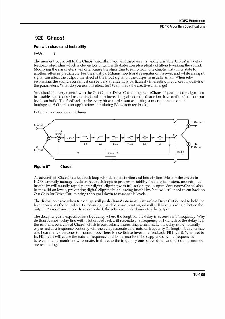
8/21/2019 MR_K2661
http://slidepdf.com/reader/full/mrk2661 271/499
KDFX Reference
KDFX Algorithm Specifications
10-189
920 Chaos!
Fun with chaos and instability
PAUs: 2
The moment you scroll to the Chaos! algorithm, you will discover it is wildly unstable. Chaos! is a delayfeedback algorithm which includes lots of gain with distortion plus plenty of filters tweaking the sound.Modifying the parameters will often cause the algorithm to jump from one chaotic instability state toanother, often unpredictably. For the most part Chaos! howls and resonates on its own, and while an inputsignal can affect the output, the effect of the input signal on the output is usually small. When self-resonating, the sound you can get can be very strange. It is particularly interesting if you keep modifyingthe parameters. What do you use this effect for? Well, that’s the creative challenge!
You should be very careful with the Out Gain or Drive Cut settings with Chaos! If you start the algorithmin a stable state (not self resonating) and start increasing gains (in the distortion drive or filters), the outputlevel can build. The feedback can be every bit as unpleasant as putting a microphone next to aloudspeaker! (There’s an application: simulating PA system feedback!)
Let’s take a closer look at Chaos!
Figure 97 Chaos!
As advertised, Chaos! is a feedback loop with delay, distortion and lots of filters. Most of the effects inKDFX carefully manage levels on feedback loops to prevent instability. In a digital system, uncontrolledinstability will usually rapidly enter digital clipping with full scale signal output. Very nasty. Chaos! alsokeeps a lid on levels, preventing digital clipping but allowing instability. You will still need to cut back onOut Gain (or Drive Cut) to bring the signal down to reasonable levels.
The distortion drive when turned up, will push Chaos! into instability unless Drive Cut is used to hold thelevel down. As the sound starts becoming unstable, your input signal will still have a strong effect on theoutput. As more and more drive is applied, the self-resonance dominates the output.
The delay length is expressed as a frequency where the length of the delay in seconds is 1/frequency. Whydo this? A short delay line with a lot of feedback will resonate at a frequency of 1/length of the delay. It isthe resonant behavior of Chaos! which is particularly interesting, which make the delay more naturallyexpressed as a frequency. Not only will the delay resonate at its natural frequency (1/length), but you mayalso hear many overtones (or harmonics). There is a switch to invert the feedback (FB Invert). When set toIn, FB Invert will cause the natural frequency and its harmonics to be suppressed while frequencies between the harmonics now resonate. In this case the frequency one octave down and its odd harmonicsare resonating.
L Input
R Input
+/- FB
Invert
Distort
Delay
LP HP Bass Treble Mid Mid
L Output
R Output
In/Out
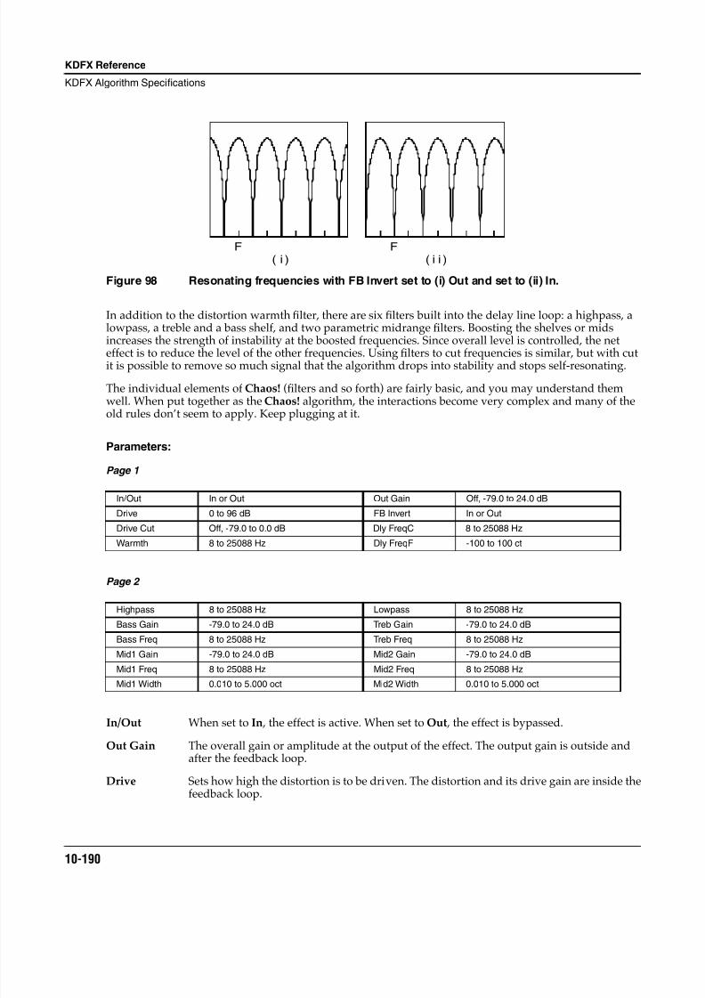
8/21/2019 MR_K2661
http://slidepdf.com/reader/full/mrk2661 272/499
10-190
KDFX Reference
KDFX Algorithm Specifications
Figure 98 Resonating frequencies with FB Invert set to (i) Out and set to (ii) In.
In addition to the distortion warmth filter, there are six filters built into the delay line loop: a highpass, alowpass, a treble and a bass shelf, and two parametric midrange filters. Boosting the shelves or midsincreases the strength of instability at the boosted frequencies. Since overall level is controlled, the neteffect is to reduce the level of the other frequencies. Using filters to cut frequencies is similar, but with cutit is possible to remove so much signal that the algorithm drops into stability and stops self-resonating.
The individual elements of Chaos! (filters and so forth) are fairly basic, and you may understand themwell. When put together as the Chaos! algorithm, the interactions become very complex and many of theold rules don’t seem to apply. Keep plugging at it.
Parameters:
Page 1
Page 2
In/Out When set to In , the effect is active. When set to Out , the effect is bypassed.
Out Gain The overall gain or amplitude at the output of the effect. The output gain is outside andafter the feedback loop.
Drive Sets how high the distortion is to be driven. The distortion and its drive gain are inside thefeedback loop.
In/Out In or Out Out Gain Off, -79.0 to 24.0 dB
Drive 0 to 96 dB FB Invert In or Out
Drive Cut Off, -79.0 to 0.0 dB Dly FreqC 8 to 25088 Hz
Warmth 8 to 25088 Hz Dly FreqF -100 to 100 ct
Highpass 8 to 25088 Hz Lowpass 8 to 25088 Hz
Bass Gain -79.0 to 24.0 dB Treb Gain -79.0 to 24.0 dB
Bass Freq 8 to 25088 Hz Treb Freq 8 to 25088 Hz
Mid1 Gain -79.0 to 24.0 dB Mid2 Gain -79.0 to 24.0 dB
Mid1 Freq 8 to 25088 Hz Mid2 Freq 8 to 25088 Hz
Mid1 Width 0.010 to 5.000 oct Mid2 Width 0.010 to 5.000 oct
F F( i ) ( i i )
8/21/2019 MR_K2661
http://slidepdf.com/reader/full/mrk2661 273/499
KDFX Reference
KDFX Algorithm Specifications
10-191
Drive Cut Reduces the signal level after the distortion. By reducing the signal level after thedistortion, Chaos! can be returned to stability while still producing a lot of distortion.Drive Cut is also inside the feedback loop.
Warmth Warmth affects the character of the distortion. Warmth reduces (at low settings) the higherfrequency distortion components without making the overall signal dull.
Dly FreqC The feedback signal path includes a short delay line which will tend to resonate at afrequency of 1/length of the delay. The delay length is therefore expressed as the resonantfrequency. Note that all the filters in the feedback loop also add delay, so with morefiltering, the resonance tuning will drift flat.
Dly FreqF The resonant frequency of the feedback delay line can be tuned sharp or flat in one cent(hundredths of a semitone) increments.
FB Invert The feedback signal can be inverted (subtracted instead of added) so that instead ofresonance at the specified frequency and its harmonics, the resonance occurs betweenthose frequencies. This is like setting resonance one octave lower, but using only the oddharmonics.
Highpass The highpass filter removes frequencies below the specified cut-off frequency. The filter isfirst order, cutting signal level at 6 dB per octave of frequency. When set to the lowestfrequency, the filter is performing very little cut of the low frequencies. When Chaos! isself-resonating, turning up the highpass frequency will cause high frequencies to beemphasized.
Lowpass The lowpass filter removes frequencies above the specified cut-off frequency. The filter isfirst order, cutting signal level at 6 dB per octave of frequency. When set to the highestfrequency, the filter is performing very little cut of the high frequencies. When Chaos! isself-resonating, turning down the lowpass frequency will cause low frequencies to beemphasized.
Bass Gain The amount of boost or cut in decibels to apply to the bass shelf filter inside the feedbackloop. Boost will emphasize frequencies below the filter frequency, while cut willemphasize frequencies above the filter frequency.
Bass Freq The frequency in Hz below which the bass shelf filter performs boost or cut.
Treb Gain The amount of boost or cut in decibels to apply to the treble shelf filter inside the feedbackloop. Boost will emphasize frequencies above the filter frequency, while cut willemphasize frequencies below the filter frequency.
Treb Freq The frequency in Hz above which the treble shelf filter performs boost or cut.
Midn Gain The amount of boost or cut in decibels to apply to the midrange parametric filter n (1 or 2)inside the feedback loop. Boost will emphasize the specified filter frequency while cut willemphasize all other frequencies.
Midn Freq The frequency in Hz at which the midrange parametricfi
lter n (1 or 2) performs boost orcut.
Midn Width The width of the frequency band in octaves of the midrange parametric filter n (1 or 2).When the filter is set for boost, a narrow band (low settings) will cause the resonatingoutput to approach a pure tone more rapidly.
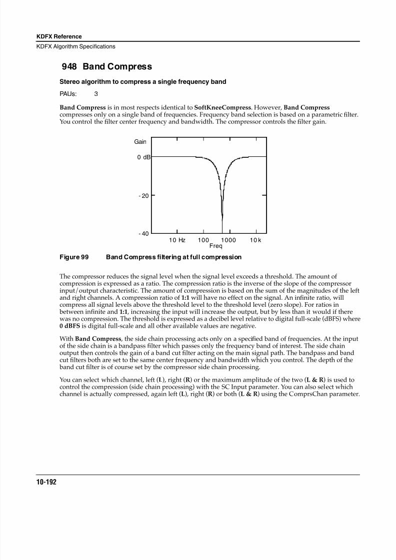
8/21/2019 MR_K2661
http://slidepdf.com/reader/full/mrk2661 274/499
10-192
KDFX Reference
KDFX Algorithm Specifications
948 Band Compress
Stereo algorithm to compress a single frequency band
PAUs: 3
Band Compress is in most respects identical to SoftKneeCompress. However, Band Compress compresses only on a single band of frequencies. Frequency band selection is based on a parametric filter.You control the filter center frequency and bandwidth. The compressor controls the filter gain.
Figure 99 Band Compress filtering at full compression
The compressor reduces the signal level when the signal level exceeds a threshold. The amount ofcompression is expressed as a ratio. The compression ratio is the inverse of the slope of the compressorinput/output characteristic. The amount of compression is based on the sum of the magnitudes of the leftand right channels. A compression ratio of 1:1 will have no effect on the signal. An infinite ratio, willcompress all signal levels above the threshold level to the threshold level (zero slope). For ratios in between infinite and 1:1 , increasing the input will increase the output, but by less than it would if therewas no compression. The threshold is expressed as a decibel level relative to digital full-scale (dBFS) where0 dBFS is digital full-scale and all other available values are negative.
With Band Compress , the side chain processing acts only on a specified band of frequencies. At the inputof the side chain is a bandpass filter which passes only the frequency band of interest. The side chainoutput then controls the gain of a band cut filter acting on the main signal path. The bandpass and bandcut filters both are set to the same center frequency and bandwidth which you control. The depth of the band cut filter is of course set by the compressor side chain processing.
You can select which channel, left (L), right (R) or the maximum amplitude of the two (L & R) is used tocontrol the compression (side chain processing) with the SC Input parameter. You can also select which
channel is actually compressed, again left (L), right (R) or both (L & R) using the ComprsChan parameter.
0 dB
- 20
- 40
Freq10 Hz 100 1000 10 k
Gain
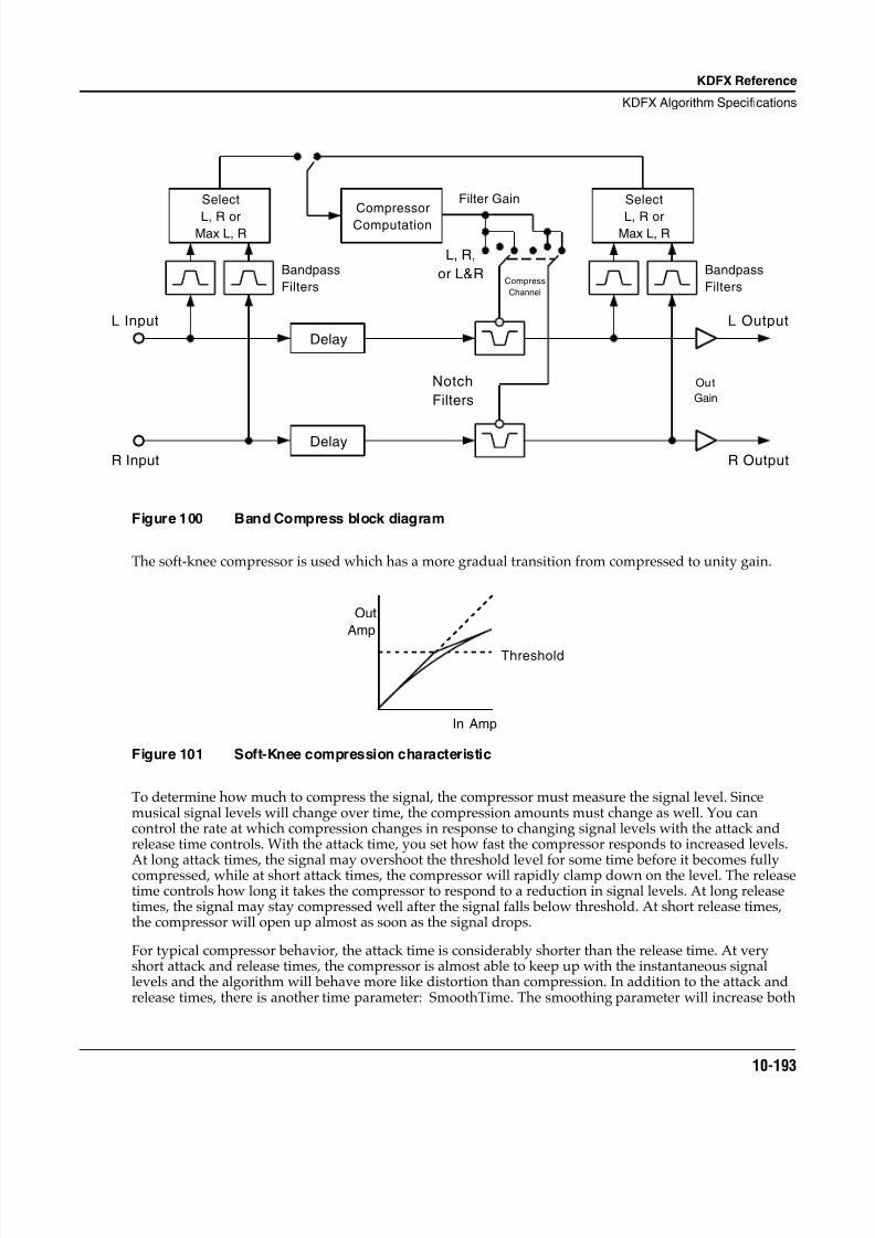
8/21/2019 MR_K2661
http://slidepdf.com/reader/full/mrk2661 275/499
KDFX Reference
KDFX Algorithm Specifications
10-193
Figure 100 Band Compress block diagram
The soft-knee compressor is used which has a more gradual transition from compressed to unity gain.
Figure 101 Soft-Knee compression characteristic
To determine how much to compress the signal, the compressor must measure the signal level. Sincemusical signal levels will change over time, the compression amounts must change as well. You cancontrol the rate at which compression changes in response to changing signal levels with the attack andrelease time controls. With the attack time, you set how fast the compressor responds to increased levels.
At long attack times, the signal may overshoot the threshold level for some time before it becomes fullycompressed, while at short attack times, the compressor will rapidly clamp down on the level. The releasetime controls how long it takes the compressor to respond to a reduction in signal levels. At long releasetimes, the signal may stay compressed well after the signal falls below threshold. At short release times,the compressor will open up almost as soon as the signal drops.
For typical compressor behavior, the attack time is considerably shorter than the release time. At veryshort attack and release times, the compressor is almost able to keep up with the instantaneous signallevels and the algorithm will behave more like distortion than compression. In addition to the attack andrelease times, there is another time parameter: SmoothTime. The smoothing parameter will increase both
L Input
R Input
Select
L, R orMax L, R
Bandpass
Filters
Delay
Compressor
Computation
Delay
Notch
Filters
Select
L, R orMax L, R
Bandpass
Filters
Filter Gain
Out
Gain
L Output
R Output
L, R,
or L&RCompress
Channel
Out
Amp
In Amp
Threshold
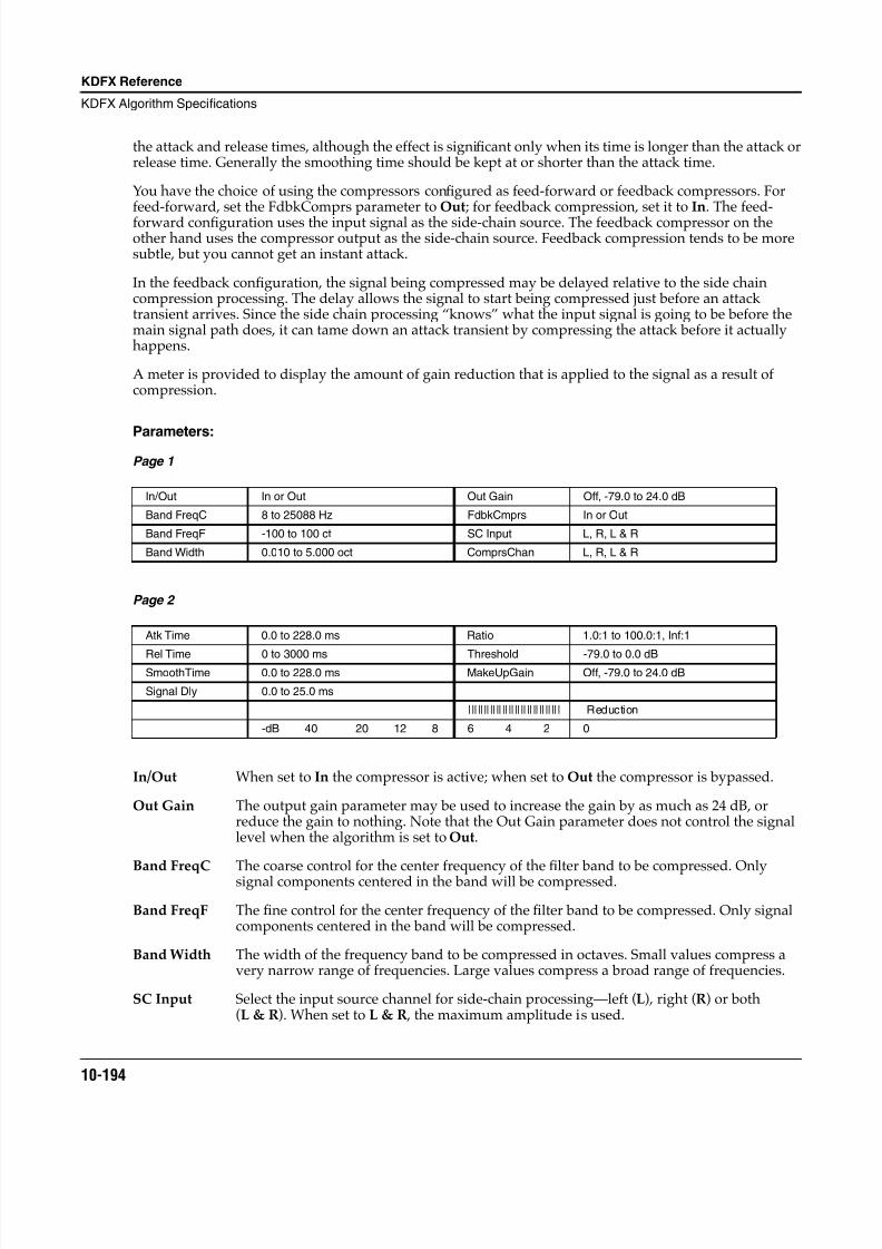
8/21/2019 MR_K2661
http://slidepdf.com/reader/full/mrk2661 276/499
10-194
KDFX Reference
KDFX Algorithm Specifications
the attack and release times, although the effect is significant only when its time is longer than the attack orrelease time. Generally the smoothing time should be kept at or shorter than the attack time.
You have the choice of using the compressors configured as feed-forward or feedback compressors. Forfeed-forward, set the FdbkComprs parameter to Out; for feedback compression, set it to In. The feed-forward configuration uses the input signal as the side-chain source. The feedback compressor on theother hand uses the compressor output as the side-chain source. Feedback compression tends to be moresubtle, but you cannot get an instant attack.
In the feedback configuration, the signal being compressed may be delayed relative to the side chaincompression processing. The delay allows the signal to start being compressed just before an attacktransient arrives. Since the side chain processing “knows” what the input signal is going to be before themain signal path does, it can tame down an attack transient by compressing the attack before it actuallyhappens.
A meter is provided to display the amount of gain reduction that is applied to the signal as a result ofcompression.
Parameters:Page 1
Page 2
In/Out When set to In the compressor is active; when set to Out the compressor is bypassed.
Out Gain The output gain parameter may be used to increase the gain by as much as 24 dB, orreduce the gain to nothing. Note that the Out Gain parameter does not control the signallevel when the algorithm is set to Out.
Band FreqC The coarse control for the center frequency of the filter band to be compressed. Onlysignal components centered in the band will be compressed.
Band FreqF The fine control for the center frequency of the filter band to be compressed. Only signalcomponents centered in the band will be compressed.
Band Width The width of the frequency band to be compressed in octaves. Small values compress avery narrow range of frequencies. Large values compress a broad range of frequencies.
SC Input Select the input source channel for side-chain processing—left (L), right (R) or both(L & R). When set to L & R , the maximum amplitude is used.
In/Out In or Out Out Gain Off, -79.0 to 24.0 dB
Band FreqC 8 to 25088 Hz FdbkCmprs In or Out
Band FreqF -100 to 100 ct SC Input L, R, L & R
Band Width 0.010 to 5.000 oct ComprsChan L, R, L & R
Atk Time 0.0 to 228.0 ms Ratio 1.0:1 to 100.0:1, Inf:1
Rel Time 0 to 3000 ms Threshold -79.0 to 0.0 dBSmoothTime 0.0 to 228.0 ms MakeUpGain Off, -79.0 to 24.0 dB
Signal Dly 0.0 to 25.0 ms
|||||||||||||||||||||||||||||| Reduction
-dB 40 20 12 8 6 4 2 0
8/21/2019 MR_K2661
http://slidepdf.com/reader/full/mrk2661 277/499
KDFX Reference
KDFX Algorithm Specifications
10-195
ComprsChan Select which input channel will receive compression processing—left, right or both. If youselect left or right, the opposite channel will pass through unaffected.
FdbkComprs A switch to set whether the compressor side chain is configured for feed-forward (Out) orfeedback (In).
Atk Time The time for the compressor to start to cut in when there is an increase in signal level(attack) above the threshold.
Rel Time The time for the compressor to stop compressing when there is a reduction in signal level(release) from a signal level above the threshold.
SmoothTime A lowpass filter in the control signal path. It is intended to smooth the output of thecompressor’s envelope detector. Smoothing will affect the attack or release times whenthe smoothing time is longer than one of the other times.
Signal Dly The time in ms by which the input signal should be delayed with respect to compressorside chain processing (i.e. side chain predelay). This allows the compression to appear totake effect just before the signal actually rises.
Ratio The compression ratio in effect above the compression threshold. High ratios are highlycompressed; low ratios are moderately compressed.
Threshold The compression threshold level in dBFS (decibels relative to full scale) above which thesignal begins to be compressed.
MakeUpGain Provides an additional control of the output gain. The Out Gain and MakeUpGaincontrols are additive (in decibels) and together may provide a maximum of 24 dB boost tooffset gain reduction due to compression.
8/21/2019 MR_K2661
http://slidepdf.com/reader/full/mrk2661 278/499
10-196
KDFX Reference
KDFX Algorithm Specifications
949 CompressDualTime
Compression with 2 release time constants
PAUs: 2
CompressDualTime is a basic compressor with two different release rates, which change from one rate toanother as the compression gain reduction crosses a threshold set by the Rel Thres (release threshold)parameter. Except for the additional release rate and release threshold parameters, this compressor is likeSoftKneeCompress.
Like a normal compressor, this compressor reduces the gain of a signal as the signal increases above thecompression threshold set with CompThres parameter. The amount of compression is expressed as a ratio.The compression ratio is the inverse of the slope of the compressor input/output characteristic. Theamount of compression is based on the side chain input signal (left, right or larger of left and rightmagnitudes). A compression ratio of 1:1 will have no effect on the signal. An infinite ratio, will compressall signal levels above the threshold level to the threshold level (zero slope). For ratios in between in finiteand 1:1 , increasing the input will increase the output, but by less than it would if there was nocompression. The threshold is expressed as a decibel level relative to digital full-scale (dBFS) where0 dBFS is digital full-scale and all other available values are negative.
To determine how much to compress the signal, the compressor must measure the signal level. Sincemusical signal levels will change over time, the compression amounts must change as well. You cancontrol the rate at which compression changes in response to changing signal levels with the attack andrelease time controls. With the attack time, you set how fast the compressor responds to increased levels.At long attack times, the signal may overshoot the threshold level for some time before it becomes fullycompressed, while at short attack times, the compressor will rapidly clamp down on the level. The releasetime controls how long it takes the compressor to respond to a reduction in signal levels. At long releasetimes, the signal may stay compressed well after the signal falls below threshold. At short release times,the compressor will open up almost as soon as the signal drops.
CompressDualTime has a special way of handling the release time. There are in fact two release times: RelTime A and Rel Time B. There is also a release threshold (Rel Thres) parameter. While the amount of
compression gain reduction exceeds the release threshold, the release time will be determined by Rel TimeA. As soon as the amount of reduction is less than the threshold, the release time changes to Rel Time B.
You can set the release times so that the release is initially very fast, and then let it slow down when itcrosses the release threshold. Likewise, you can have a very slow release, which suddenly speeds up asreduction reaches the release threshold. Be sure to watch the reduction meter to follow what is happeningas you change the parameters.
You can select which channel, left (L), right (R) or the maximum amplitude of the two (L & R) is used tocontrol the compression (side chain processing) with the SC Input parameter. You can also select whichchannel is actually compressed, again left (L), right (R) or both (L & R) using the ComprsChan parameter.
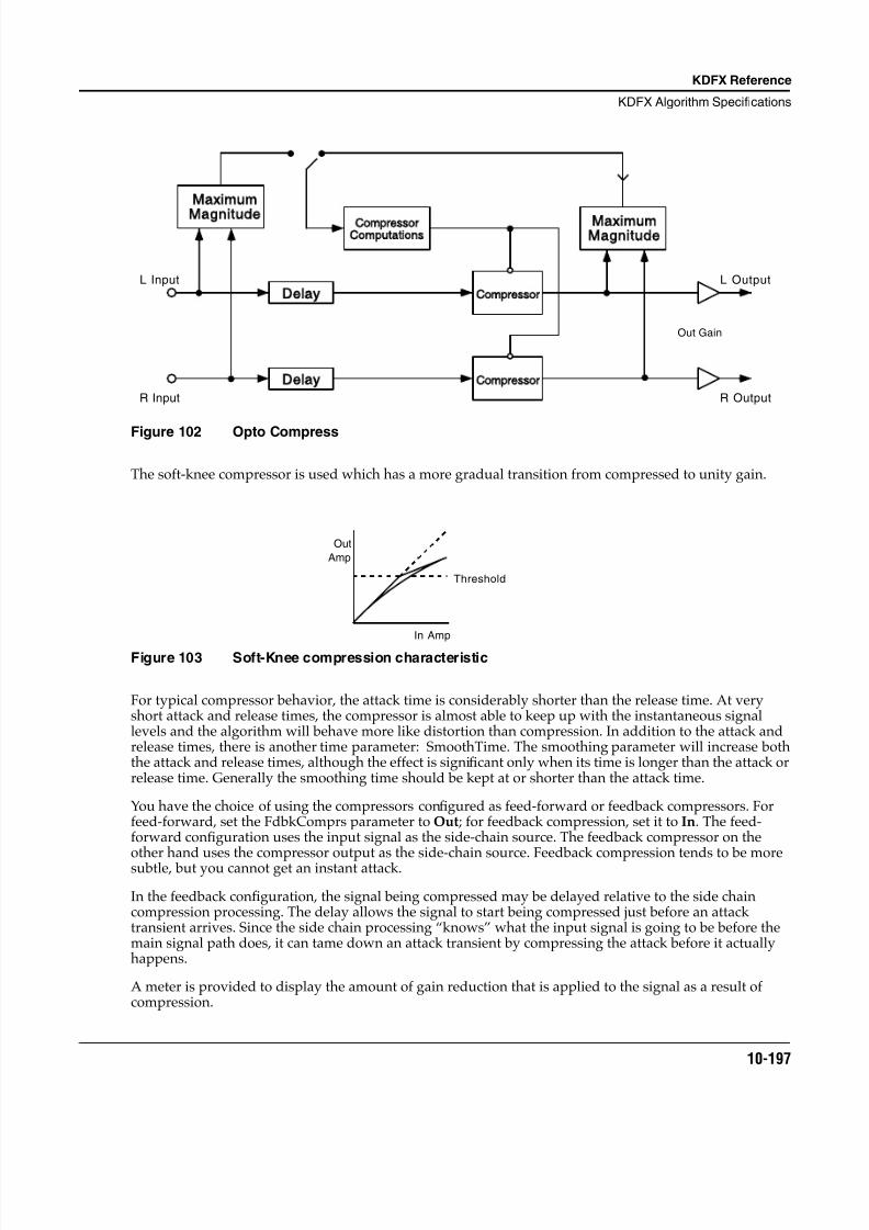
8/21/2019 MR_K2661
http://slidepdf.com/reader/full/mrk2661 279/499
KDFX Reference
KDFX Algorithm Specifications
10-197
Figure 102 Opto Compress
The soft-knee compressor is used which has a more gradual transition from compressed to unity gain.
Figure 103 Soft-Knee compression characteristic
For typical compressor behavior, the attack time is considerably shorter than the release time. At veryshort attack and release times, the compressor is almost able to keep up with the instantaneous signallevels and the algorithm will behave more like distortion than compression. In addition to the attack andrelease times, there is another time parameter: SmoothTime. The smoothing parameter will increase boththe attack and release times, although the effect is significant only when its time is longer than the attack orrelease time. Generally the smoothing time should be kept at or shorter than the attack time.
You have the choice of using the compressors configured as feed-forward or feedback compressors. Forfeed-forward, set the FdbkComprs parameter to Out; for feedback compression, set it to In. The feed-forward configuration uses the input signal as the side-chain source. The feedback compressor on theother hand uses the compressor output as the side-chain source. Feedback compression tends to be moresubtle, but you cannot get an instant attack.
In the feedback configuration, the signal being compressed may be delayed relative to the side chaincompression processing. The delay allows the signal to start being compressed just before an attacktransient arrives. Since the side chain processing “knows” what the input signal is going to be before themain signal path does, it can tame down an attack transient by compressing the attack before it actuallyhappens.
A meter is provided to display the amount of gain reduction that is applied to the signal as a result ofcompression.
L Input
R Input
L Output
R Output
Maximum
Magnitude CompressorComputations
Delay
Delay
Compressor
Compressor
MaximumMagnitude
Out Gain
Out
Amp
In Amp
Threshold
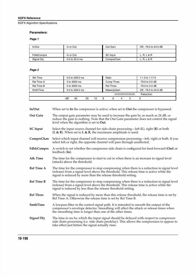
8/21/2019 MR_K2661
http://slidepdf.com/reader/full/mrk2661 280/499
10-198
KDFX Reference
KDFX Algorithm Specifications
Parameters:
Page 1
Page 2
In/Out When set to In the compressor is active; when set to Out the compressor is bypassed.
Out Gain The output gain parameter may be used to increase the gain by as much as 24 dB, orreduce the gain to nothing. Note that the Out Gain parameter does not control the signallevel when the algorithm is set to Out.
SC Input Select the input source channel for side-chain processing—left (L), right (R) or both(L & R). When set to L & R , the maximum amplitude is used.
ComprsChan Select which input channel will receive compression processing—left, right or both. If youselect left or right, the opposite channel will pass through unaffected.
FdbkComprs A switch to set whether the compressor side chain is configured for feed-forward (Out) orfeedback (In).
Atk Time The time for the compressor to start to cut in when there is an increase in signal level(attack) above the threshold.
Rel Time A The time for the compressor to stop compressing when there is a reduction in signal level(release) from a signal level above the threshold. This release time is active while thesignal is reduced by more than the release threshold setting.
Rel Time B The time for the compressor to stop compressing when there is a reduction in signal level(release) from a signal level above the threshold. This release time is active while thesignal is reduced by less than the release threshold setting.
Rel Thres When the signal is reduced by more than this release threshold, the release time is set byRel Time A. Otherwise the release time is set by Rel Time B.
SmthTime A lowpass filter in the control signal path. It is intended to smooth the output of thecompressor’s envelope detector. Smoothing will affect the attack or release times whenthe smoothing time is longer than one of the other times.
Signal Dly The time in ms by which the input signal should be delayed with respect to compressorside chain processing (i.e. side chain predelay). This allows the compression to appear totake effect just before the signal actually rises.
In/Out In or Out Out Gain Off, -79.0 to 24.0 dB
FdbkComprs In or Out SC Input L, R, L & R
Signal Dly 0.0 to 25.0 ms ComprsChan L, R, L & R
Atk Time 0.0 to 228.0 ms Ratio 1:1.0 to 1:17.0
Rel Time A 0 to 3000 ms Comp Thres -79.0 to 0.0 dB
Rel Time B 0 to 3000 ms Rel Thres -79.0 to 0.0 dB
SmthTime 0.0 to 228.0 ms MakeUpGain Off, -79.0 to 24.0 dB
|||||||||||||||||||||||||||||| Reduction
-dB 40 20 12 8 6 4 2 0

8/21/2019 MR_K2661
http://slidepdf.com/reader/full/mrk2661 281/499
KDFX Reference
KDFX Algorithm Specifications
10-199
Ratio The compression ratio in effect above the compression threshold. High ratios are highlycompressed; low ratios are moderately compressed.
Comp Thres The compression threshold level in dBFS (decibels relative to full scale) above which thesignal begins to be compressed.
MakeUpGain Provides an additional control of the output gain. The Out Gain and MakeUpGaincontrols are additive (in decibels) and together may provide a maximum of 24 dB boost tooffset gain reduction due to compression.
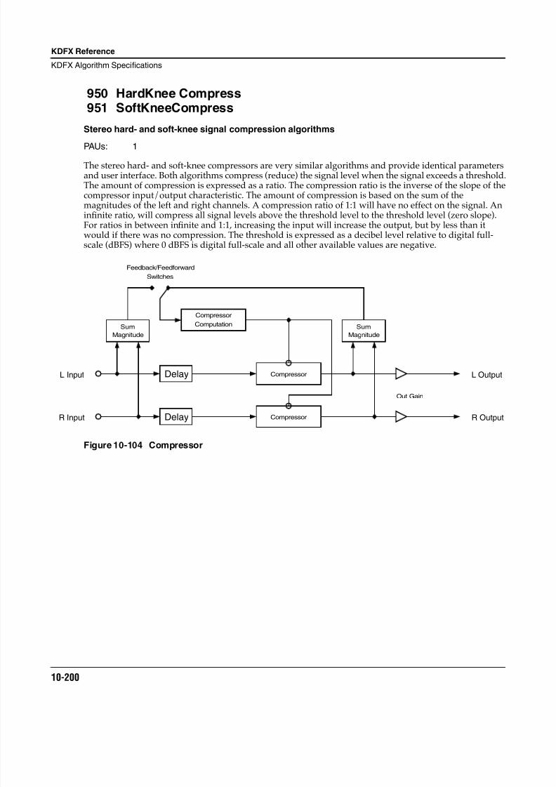
8/21/2019 MR_K2661
http://slidepdf.com/reader/full/mrk2661 282/499
10-200
KDFX Reference
KDFX Algorithm Specifications
950 HardKnee Compress951 SoftKneeCompress
Stereo hard- and soft-knee signal compression algorithms
PAUs: 1
The stereo hard- and soft-knee compressors are very similar algorithms and provide identical parametersand user interface. Both algorithms compress (reduce) the signal level when the signal exceeds a threshold.The amount of compression is expressed as a ratio. The compression ratio is the inverse of the slope of thecompressor input/output characteristic. The amount of compression is based on the sum of themagnitudes of the left and right channels. A compression ratio of 1:1 will have no effect on the signal. Aninfinite ratio, will compress all signal levels above the threshold level to the threshold level (zero slope).For ratios in between infinite and 1:1, increasing the input will increase the output, but by less than itwould if there was no compression. The threshold is expressed as a decibel level relative to digital full-scale (dBFS) where 0 dBFS is digital full-scale and all other available values are negative.
Figure 10-104 Compressor
Delay
Delay
Compressor
Compressor
Sum
Magnitude Magnitude
Sum
Feedback/Feedforward
Switches
Out Gain
L Output
R Output
L Input
R Input
Compressor
Computation
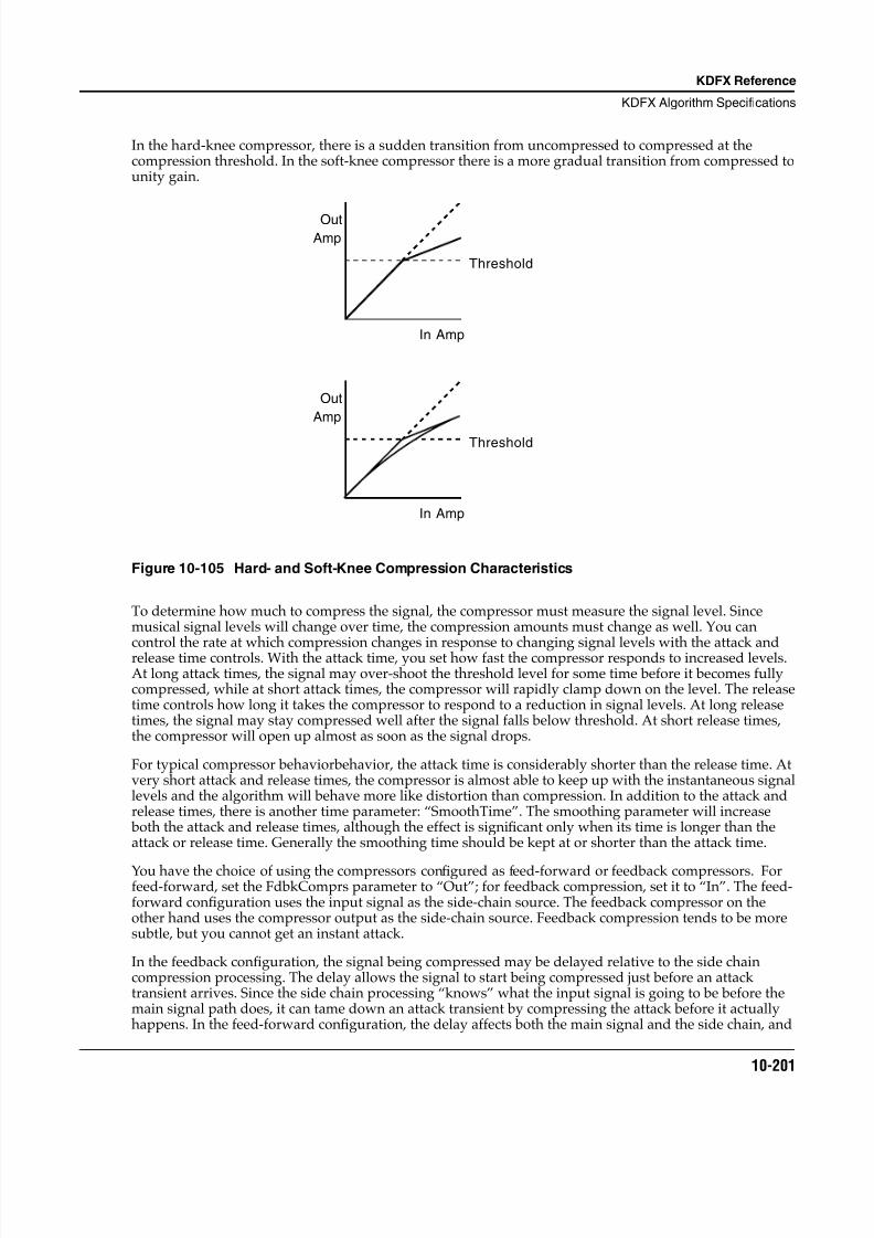
8/21/2019 MR_K2661
http://slidepdf.com/reader/full/mrk2661 283/499
KDFX Reference
KDFX Algorithm Specifications
10-201
In the hard-knee compressor, there is a sudden transition from uncompressed to compressed at thecompression threshold. In the soft-knee compressor there is a more gradual transition from compressed tounity gain.
Figure 10-105 Hard- and Soft-Knee Compression Characteristics
To determine how much to compress the signal, the compressor must measure the signal level. Sincemusical signal levels will change over time, the compression amounts must change as well. You cancontrol the rate at which compression changes in response to changing signal levels with the attack andrelease time controls. With the attack time, you set how fast the compressor responds to increased levels.At long attack times, the signal may over-shoot the threshold level for some time before it becomes fullycompressed, while at short attack times, the compressor will rapidly clamp down on the level. The releasetime controls how long it takes the compressor to respond to a reduction in signal levels. At long releasetimes, the signal may stay compressed well after the signal falls below threshold. At short release times,the compressor will open up almost as soon as the signal drops.
For typical compressor behaviorbehavior, the attack time is considerably shorter than the release time. Atvery short attack and release times, the compressor is almost able to keep up with the instantaneous signallevels and the algorithm will behave more like distortion than compression. In addition to the attack andrelease times, there is another time parameter: “SmoothTime”. The smoothing parameter will increase both the attack and release times, although the effect is significant only when its time is longer than theattack or release time. Generally the smoothing time should be kept at or shorter than the attack time.
You have the choice of using the compressors configured as feed-forward or feedback compressors. Forfeed-forward, set the FdbkComprs parameter to “Out”; for feedback compression, set it to “In”. The feed-forward configuration uses the input signal as the side-chain source. The feedback compressor on theother hand uses the compressor output as the side-chain source. Feedback compression tends to be moresubtle, but you cannot get an instant attack.
In the feedback configuration, the signal being compressed may be delayed relative to the side chaincompression processing. The delay allows the signal to start being compressed just before an attacktransient arrives. Since the side chain processing “knows” what the input signal is going to be before themain signal path does, it can tame down an attack transient by compressing the attack before it actuallyhappens. In the feed-forward configuration, the delay affects both the main signal and the side chain, and
In Amp
OutAmp
Threshold
Out
Amp
In Amp
Threshold
8/21/2019 MR_K2661
http://slidepdf.com/reader/full/mrk2661 284/499
10-202
KDFX Reference
KDFX Algorithm Specifications
so is of limited usefulness. In compressors which use more than 1 PAU, the delay affects the main signalonly, regardless of the side chain configuration.
A meter is provided to display the amount of gain reduction that is applied to the signal as a result ofcompression.
Parameters
Page 1
Page 2
In/Out When set to “In” the compressor is active; when set to “Out” the compressor is bypassed.
Out Gain Compressing the signal causes a reduction in signal level. To compensate, the output gainparameter may be used to increase the gain by as much as 24 dB. Note that the Out Gainparameter does not control the signal level when the algorithm is set to “Out”.
FdbkComprs A switch to set whether the compressor side chain is configured for feed-forward (Out) orfeedback (In).
Atk Time The time for the compressor to start to cut in when there is an increase in signal level(attack) above the threshold.
Rel Time The time for the compressor to stop compressing when there is a reduction in signal level(release) from a signal level above the threshold.
SmoothTime A lowpass filter in the control signal path. It is intended to smooth the output of theexpander’s envelope detector. Smoothing will affect the attack or release times when thesmoothing time is longer than one of the other times.
Signal Dly For the feed-forward setting, Signal Dly is the time in ms by which the input signal should be delayed with respect to compressor side chain processing (i.e. side chain pre-delay).This allows the compression to appear to take effect just before the signal actually rises.For feedback compression, this parameter causes both the side-chain and main signal pathto be delayed together for limited benefit.
Ratio The compression ratio. High ratios are highly compressed; low ratios are moderatelycompressed.
Threshold The threshold level in dBFS (decibels relative to full scale) above which the signal beginsto be compressed.
MakeUpGain Provides an additional control of the output gain. The Out Gain and MakeUpGaincontrols are additive (in decibels) and together may provide a maximum of 24 dB boost tooffset gain reduction due to compression.
In/Out In or Out Out Gain Off, -79.0 to 24.0 dB
FdbkComprs In or Out
Atk Time 0.0 to 228.0 ms Ratio 1.0:1 to 100:1, Inf:1
Rel Time 0 to 3000 ms Threshold -79.0 to 0.0dBSmoothTime 0.0 to 228.0 ms MakeUpGain Off, -79.0 to 24.0 dB
Signal Dly 0.0 to 25.0ms
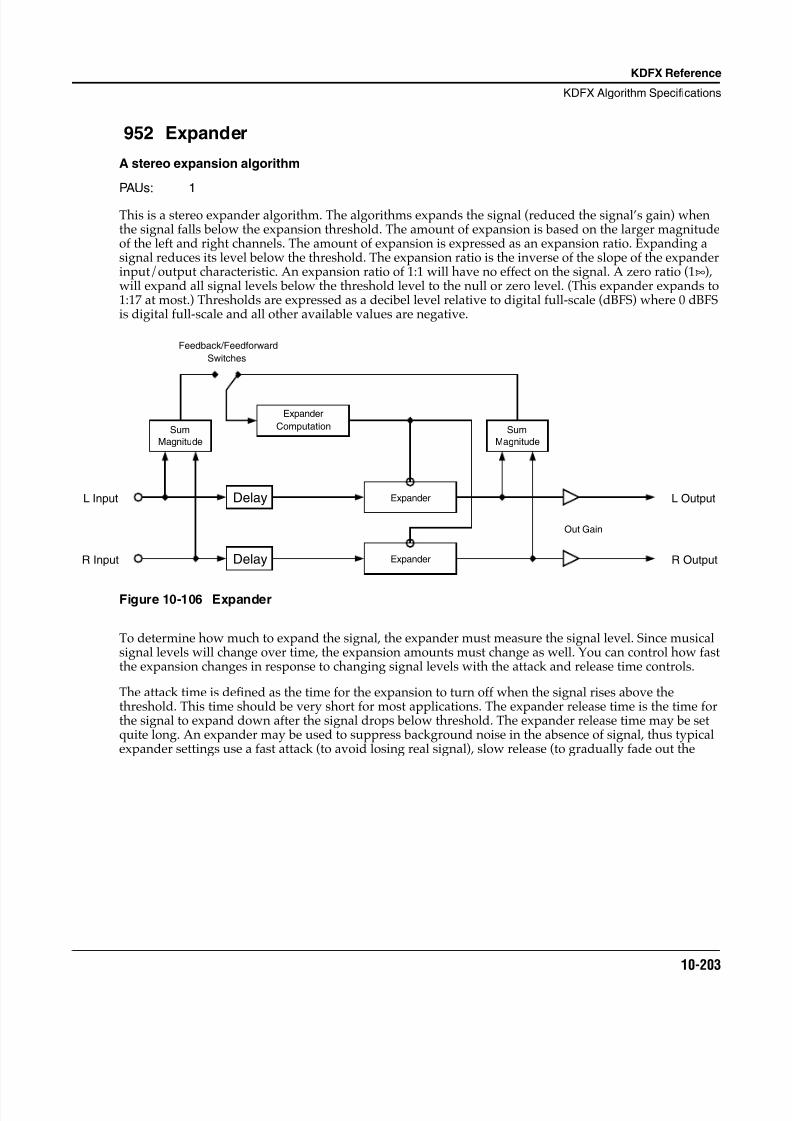
8/21/2019 MR_K2661
http://slidepdf.com/reader/full/mrk2661 285/499
KDFX Reference
KDFX Algorithm Specifications
10-203
952 Expander
A stereo expansion algorithm
PAUs: 1
This is a stereo expander algorithm. The algorithms expands the signal (reduced the signal’s gain) whenthe signal falls below the expansion threshold. The amount of expansion is based on the larger magnitudeof the left and right channels. The amount of expansion is expressed as an expansion ratio. Expanding asignal reduces its level below the threshold. The expansion ratio is the inverse of the slope of the expanderinput/output characteristic. An expansion ratio of 1:1 will have no effect on the signal. A zero ratio (1:∞),will expand all signal levels below the threshold level to the null or zero level. (This expander expands to1:17 at most.) Thresholds are expressed as a decibel level relative to digital full-scale (dBFS) where 0 dBFSis digital full-scale and all other available values are negative.
Figure 10-106 Expander
To determine how much to expand the signal, the expander must measure the signal level. Since musicalsignal levels will change over time, the expansion amounts must change as well. You can control how fastthe expansion changes in response to changing signal levels with the attack and release time controls.
The attack time is defined as the time for the expansion to turn off when the signal rises above thethreshold. This time should be very short for most applications. The expander release time is the time forthe signal to expand down after the signal drops below threshold. The expander release time may be setquite long. An expander may be used to suppress background noise in the absence of signal, thus typicalexpander settings use a fast attack (to avoid losing real signal), slow release (to gradually fade out the
Delay
Delay
Expander
Expander
Sum
Magnitude Magnitude
Sum
Feedback/Feedforward
Switches
Out Gain
L Output
R Output
L Input
R Input
Expander
Computation
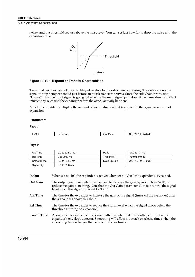
8/21/2019 MR_K2661
http://slidepdf.com/reader/full/mrk2661 286/499
10-204
KDFX Reference
KDFX Algorithm Specifications
noise), and the threshold set just above the noise level. You can set just how far to drop the noise with theexpansion ratio.
Figure 10-107 Expansion Transfer Characteristic
The signal being expanded may be delayed relative to the side chain processing. The delay allows thesignal to stop being expanded just before an attack transient arrives. Since the side chain processing
“knows” what the input signal is going to be before the main signal path does, it can tame down an attacktransient by releasing the expander before the attack actually happens.
A meter is provided to display the amount of gain reduction that is applied to the signal as a result ofexpansion.
Parameters
Page 1
Page 2
In/Out When set to “In” the expander is active; when set to “Out” the expander is bypassed.
Out Gain The output gain parameter may be used to increase the gain by as much as 24 dB, orreduce the gain to nothing. Note that the Out Gain parameter does not control the signallevel when the algorithm is set to “Out”.
Atk Time The time for the expander to increase the gain of the signal (turns off the expander) afterthe signal rises above threshold.
Rel Time The time for the expander to reduce the signal level when the signal drops below thethreshold (turning on expansion).
SmoothTime A lowpass filter in the control signal path. It is intended to smooth the output of theexpander’s envelope detector. Smoothing will affect the attack or release times when thesmoothing time is longer than one of the other times.
In/Out In or Out Out Gain Off, -79.0 to 24.0 dB
Atk Time 0.0 to 228.0 ms Ratio 1:1.0 to 1:17.0
Rel Time 0 to 3000 ms Threshold -79.0 to 0.0 dB
SmoothTime 0.0 to 228.0 ms MakeUpGain Off, -79.0 to 24.0 dB
Signal Dly 0.0 to 25.0 ms
Out
Amp
In Amp
Threshold
8/21/2019 MR_K2661
http://slidepdf.com/reader/full/mrk2661 287/499
KDFX Reference
KDFX Algorithm Specifications
10-205
Signal Dly The time in ms by which the input signal should be delayed with respect to expander sidechain processing (i.e. side chain pre-delay). This allows the expansion to appear to turn off just before the signal actually rises.
Ratio The expansion ratio. High values (1:17 max) are highly expanded, low values (1:1 min) aremoderately expanded.
Threshold The expansion threshold level in dBFS (decibels relative to full scale) below which thesignal begins to be expanded.
MakeUpGain Provides an additional control of the output gain. The Out Gain and MakeUpGaincontrols are additive (in decibels) and together may provide a maximum of 24 dB boost tooffset gain reduction due to expansion.
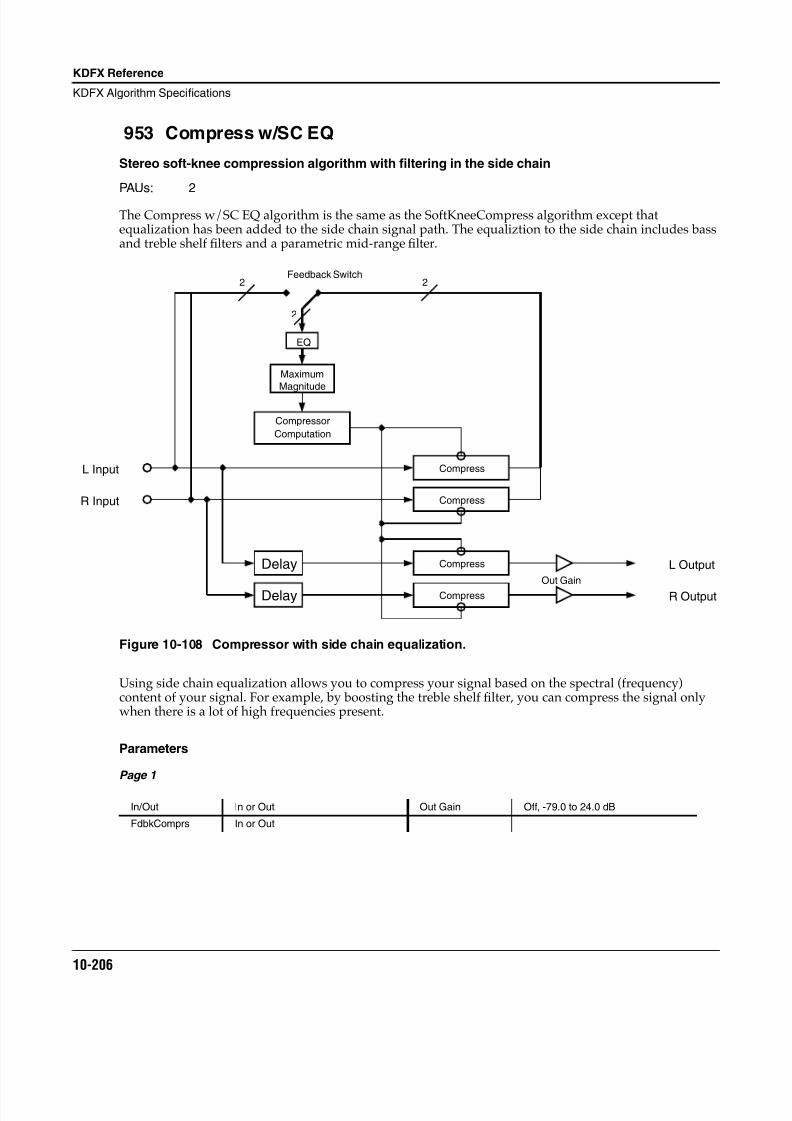
8/21/2019 MR_K2661
http://slidepdf.com/reader/full/mrk2661 288/499
10-206
KDFX Reference
KDFX Algorithm Specifications
953 Compress w/SC EQ
Stereo soft-knee compression algorithm with filtering in the side chain
PAUs: 2
The Compress w/SC EQ algorithm is the same as the SoftKneeCompress algorithm except thatequalization has been added to the side chain signal path. The equaliztion to the side chain includes bassand treble shelf filters and a parametric mid-range filter.
Figure 10-108 Compressor with side chain equalization.
Using side chain equalization allows you to compress your signal based on the spectral (frequency)content of your signal. For example, by boosting the treble shelf filter, you can compress the signal onlywhen there is a lot of high frequencies present.
Parameters
Page 1
In/Out In or Out Out Gain Off, -79.0 to 24.0 dB
FdbkComprs In or Out
Delay
Delay
EQ
Compressor
Computation
Compress
Compress
2
2 2
L Input
R Input
L Output
R Output
Feedback Switch
Out Gain
Maximum
Magnitude
Compress
Compress
8/21/2019 MR_K2661
http://slidepdf.com/reader/full/mrk2661 289/499
KDFX Reference
KDFX Algorithm Specifications
10-207
Page 2
Page 3
In/Out When set to “In” the compressor is active; when set to “Out” the compressor is bypassed.
Out Gain Compressing the signal causes a reduction in signal level. To compensate, the output gainparameter may be used to increase the gain by as much as 24 dB. Note that the Out Gainparameter does not control the signal level when the algorithm is set to “Out”.
FdbkComprs A switch to set whether the compressor side chain is configured for feed-forward (Out) orfeedback (In).
Atk Time The time for the compressor to start to cut in when there is an increase in signal level(attack) above the threshold.
Rel Time The time for the compressor to stop compressing when there is a reduction in signal level(release) from a signal level above the threshold.
SmoothTime A lowpass filter in the control signal path. It is intended to smooth the output of theexpander’s envelope detector. Smoothing will affect the attack or release times when thesmoothing time is longer than one of the other times.
Signal Dly The time in ms by which the input signal should be delayed with respect to compressorside chain processing (i.e. side chain pre-delay). This allows the compression to appear totake effect just before the signal actually rises.
Ratio The compression ratio. High ratios are highly compressed; low ratios are moderatelycompressed.
Threshold The threshold level in dBFS (decibels relative to full scale) above which the signal beginsto be compressed.
MakeUpGain Provides an additional control of the output gain. The Out Gain and MakeUpGaincontrols are additive (in decibels) and together may provide a maximum of 24 dB boost tooffset gain reduction due to compression.
SCBassGain The amount of boost or cut that the side chain bass shelving filter should apply to the lowfrequency signals in dB. Every increase of 6 dB approximately doubles the amplitude ofthe signal. Positive values boost the bass signal below the specified frequency. Negativevalues cut the bass signal below the specified frequency.
SCBassFreq The center frequency of the side chain bass shelving filter in intervals of one semitone.
Atk Time 0.0 to 228.0 ms Ratio 1.0:1 to 100.0:1, Inf:1
Rel Time 0 to 3000 ms Threshold -79.0 to 24.0 dB
SmoothTime 0.0 to 228.0 ms MakeUpGain Off, -79.0 to 24.0 dBSignal Dly 0.0 to 25.0 ms
SCBassGain -79.0 to 24.0 dB SCTrebGain -79.0 to 24.0 dB
SCBassFreq 16 to 25088 Hz SCTrebFreq 16 to 25088 Hz
SCMidGain -79.0 to 24.0 dB
SCMidFreq 16 to 25088 Hz
SCMidWidth 0.010 to 5.000 oct
8/21/2019 MR_K2661
http://slidepdf.com/reader/full/mrk2661 290/499
10-208
KDFX Reference
KDFX Algorithm Specifications
SCTrebGain The amount of boost or cut that the side chain treble shelving filter should apply to thehigh frequency signals in dB. Every increase of 6 dB approximately doubles the amplitudeof the signal. Positive values boost the treble signal above the specified frequency.Negative values cut the treble signal above the specified frequency.
SCTrebFreq The center frequency of the side chain treble shelving filters in intervals of one semitone.
SCMidGain The amount of boost or cut that the side chain parametric mid filter should apply in dB tothe specified frequency band. Every increase of 6 dB approximately doubles theamplitude of the signal. Positive values boost the signal at the specified frequency.Negative values cut the signal at the specified frequency.
SCMidFreq The center frequency of the side chain parametric mid filter in intervals of one semitone.The boost or cut will be at a maximum at this frequency.
SCMidWidth The bandwidth of the side chain parametric mid filter may be adjusted. You specify the bandwidth in octaves. Small values result in a very narrow filter response. Large valuesresult in a very broad response.
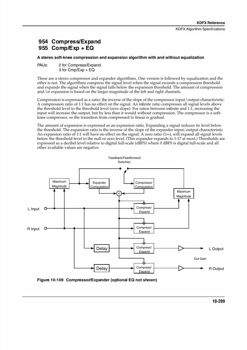
8/21/2019 MR_K2661
http://slidepdf.com/reader/full/mrk2661 291/499
KDFX Reference
KDFX Algorithm Specifications
10-209
954 Compress/Expand955 Comp/Exp + EQ
A stereo soft-knee compression and expansion algorithm with and without equalization
PAUs: 2 for Compress/Expand3 for Cmp/Exp + EQ
These are a stereo compressor and expander algorithms. One version is followed by equalization and theother is not. The algorithms compress the signal level when the signal exceeds a compression thresholdand expands the signal when the signal falls below the expansion threshold. The amount of compressionand/or expansion is based on the larger magnitude of the left and right channels.
Compression is expressed as a ratio: the inverse of the slope of the compressor input/output characteristic.A compression ratio of 1:1 has no effect on the signal. An infinite ratio compresses all signal levels abovethe threshold level to the threshold level (zero slope). For ratios between infinite and 1:1, increasing theinput will increase the output, but by less than it would without compression. The compressor is a soft-knee compressor, so the transition from compressed to linear is gradual.
The amount of expansion is expressed as an expansion ratio. Expanding a signal reduces its level belowthe threshold. The expansion ratio is the inverse of the slope of the expander input/output characteristic.An expansion ratio of 1:1 will have no effect on the signal. A zero ratio (1:∞), will expand all signal levels below the threshold level to the null or zero level. (This expander expands to 1:17 at most.) Thresholds areexpressed as a decibel level relative to digital full-scale (dBFS) where 0 dBFS is digital full-scale and allother available values are negative.
Figure 10-109 Compressor/Expander (optional EQ not shown)
R Input
L Input
Maximum
Magnitude ExpanderComputation
Compress/
Expand
Compress/
Expand
Compress/
Expand
Compress/
Expand
Magnitude
Maximum
Delay
Delay
ComputationCompressor
Feedback/Feedforward
Switches
L Output
R Output
Out Gain
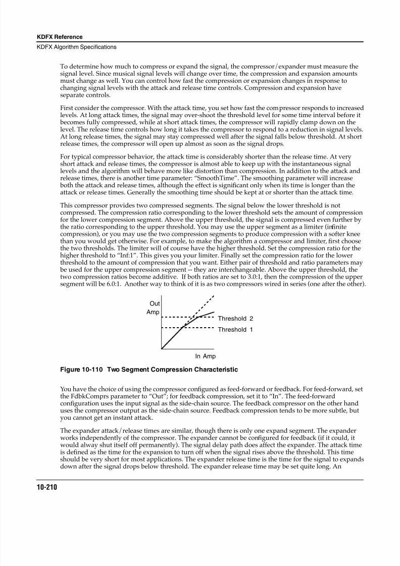
8/21/2019 MR_K2661
http://slidepdf.com/reader/full/mrk2661 292/499
10-210
KDFX Reference
KDFX Algorithm Specifications
To determine how much to compress or expand the signal, the compressor/expander must measure thesignal level. Since musical signal levels will change over time, the compression and expansion amountsmust change as well. You can control how fast the compression or expansion changes in response tochanging signal levels with the attack and release time controls. Compression and expansion haveseparate controls.
First consider the compressor. With the attack time, you set how fast the compressor responds to increasedlevels. At long attack times, the signal may over-shoot the threshold level for some time interval before it becomes fully compressed, while at short attack times, the compressor will rapidly clamp down on thelevel. The release time controls how long it takes the compressor to respond to a reduction in signal levels.At long release times, the signal may stay compressed well after the signal falls below threshold. At shortrelease times, the compressor will open up almost as soon as the signal drops.
For typical compressor behavior, the attack time is considerably shorter than the release time. At veryshort attack and release times, the compressor is almost able to keep up with the instantaneous signallevels and the algorithm will behave more like distortion than compression. In addition to the attack andrelease times, there is another time parameter: “SmoothTime”. The smoothing parameter will increase both the attack and release times, although the effect is significant only when its time is longer than theattack or release times. Generally the smoothing time should be kept at or shorter than the attack time.
This compressor provides two compressed segments. The signal below the lower threshold is notcompressed. The compression ratio corresponding to the lower threshold sets the amount of compressionfor the lower compression segment. Above the upper threshold, the signal is compressed even further bythe ratio corresponding to the upper threshold. You may use the upper segment as a limiter (infinitecompression), or you may use the two compression segments to produce compression with a softer kneethan you would get otherwise. For example, to make the algorithm a compressor and limiter, first choosethe two thresholds. The limiter will of course have the higher threshold. Set the compression ratio for thehigher threshold to “Inf:1”. This gives you your limiter. Finally set the compression ratio for the lowerthreshold to the amount of compression that you want. Either pair of threshold and ratio parameters may be used for the upper compression segment -- they are interchangeable. Above the upper threshold, thetwo compression ratios become additive. If both ratios are set to 3.0:1, then the compression of the uppersegment will be 6.0:1. Another way to think of it is as two compressors wired in series (one after the other).
Figure 10-110 Two Segment Compression Characteristic
You have the choice of using the compressor configured as feed-forward or feedback. For feed-forward, set
the FdbkComprs parameter to “Out”; for feedback compression, set it to “In”. The feed-forwardconfiguration uses the input signal as the side-chain source. The feedback compressor on the other handuses the compressor output as the side-chain source. Feedback compression tends to be more subtle, butyou cannot get an instant attack.
The expander attack/release times are similar, though there is only one expand segment. The expanderworks independently of the compressor. The expander cannot be configured for feedback (if it could, itwould alway shut itself off permanently). The signal delay path does affect the expander. The attack timeis defined as the time for the expansion to turn off when the signal rises above the threshold. This timeshould be very short for most applications. The expander release time is the time for the signal to expandsdown after the signal drops below threshold. The expander release time may be set quite long. An
In Amp
Out
Amp
Threshold 1
Threshold 2
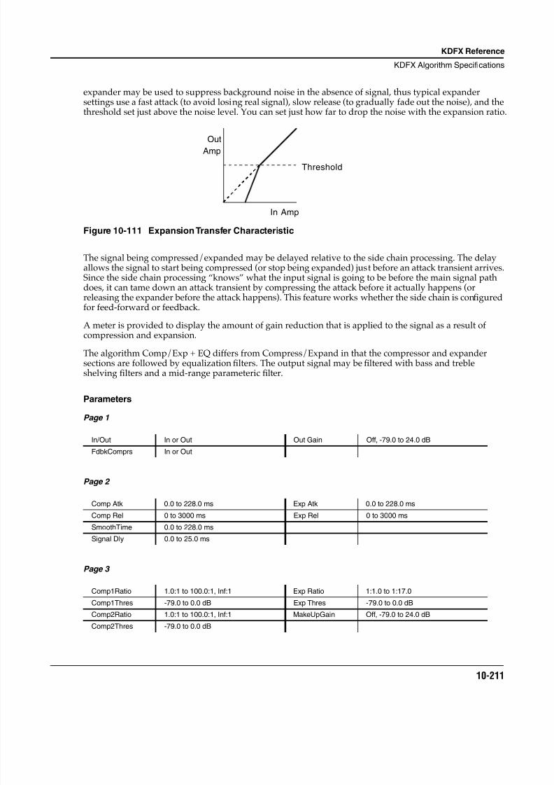
8/21/2019 MR_K2661
http://slidepdf.com/reader/full/mrk2661 293/499
KDFX Reference
KDFX Algorithm Specifications
10-211
expander may be used to suppress background noise in the absence of signal, thus typical expandersettings use a fast attack (to avoid losing real signal), slow release (to gradually fade out the noise), and thethreshold set just above the noise level. You can set just how far to drop the noise with the expansion ratio.
Figure 10-111 Expansion Transfer Characteristic
The signal being compressed/expanded may be delayed relative to the side chain processing. The delayallows the signal to start being compressed (or stop being expanded) just before an attack transient arrives.Since the side chain processing “knows” what the input signal is going to be before the main signal pathdoes, it can tame down an attack transient by compressing the attack before it actually happens (orreleasing the expander before the attack happens). This feature works whether the side chain is configuredfor feed-forward or feedback.
A meter is provided to display the amount of gain reduction that is applied to the signal as a result ofcompression and expansion.
The algorithm Comp/Exp + EQ differs from Compress/Expand in that the compressor and expandersections are followed by equalization filters. The output signal may be filtered with bass and trebleshelving filters and a mid-range parameteric filter.
Parameters
Page 1
Page 2
Page 3
In/Out In or Out Out Gain Off, -79.0 to 24.0 dB
FdbkComprs In or Out
Comp Atk 0.0 to 228.0 ms Exp Atk 0.0 to 228.0 ms
Comp Rel 0 to 3000 ms Exp Rel 0 to 3000 ms
SmoothTime 0.0 to 228.0 ms
Signal Dly 0.0 to 25.0 ms
Comp1Ratio 1.0:1 to 100.0:1, Inf:1 Exp Ratio 1:1.0 to 1:17.0
Comp1Thres -79.0 to 0.0 dB Exp Thres -79.0 to 0.0 dB
Comp2Ratio 1.0:1 to 100.0:1, Inf:1 MakeUpGain Off, -79.0 to 24.0 dB
Comp2Thres -79.0 to 0.0 dB
OutAmp
In Amp
Threshold
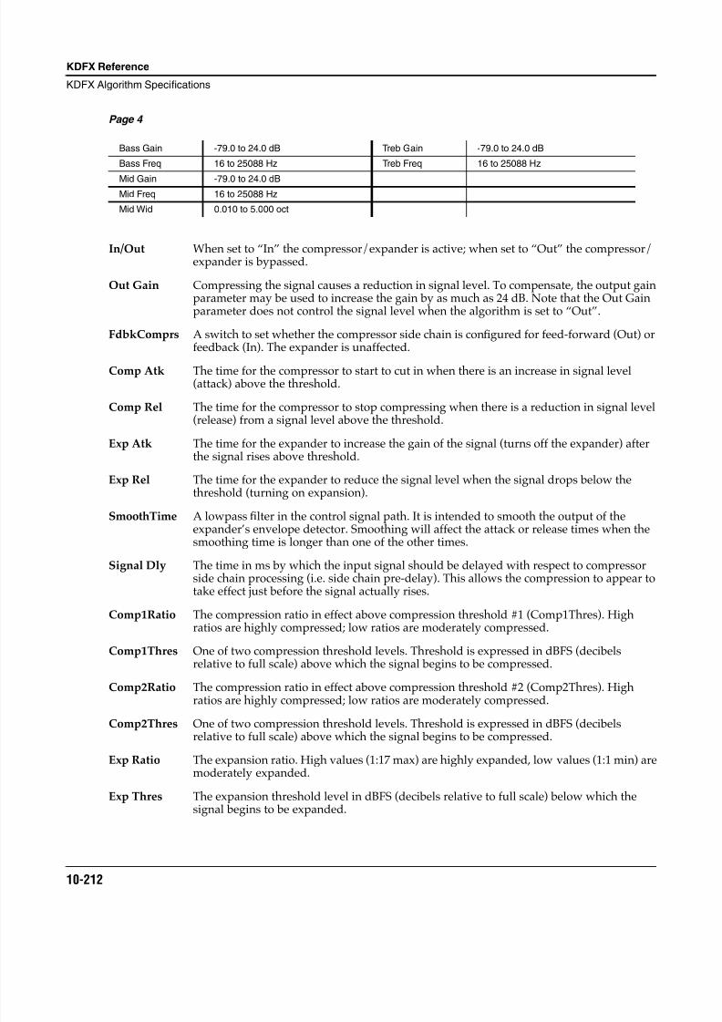
8/21/2019 MR_K2661
http://slidepdf.com/reader/full/mrk2661 294/499
10-212
KDFX Reference
KDFX Algorithm Specifications
Page 4
In/Out When set to “In” the compressor/expander is active; when set to “Out” the compressor/expander is bypassed.
Out Gain Compressing the signal causes a reduction in signal level. To compensate, the output gainparameter may be used to increase the gain by as much as 24 dB. Note that the Out Gainparameter does not control the signal level when the algorithm is set to “Out”.
FdbkComprs A switch to set whether the compressor side chain is configured for feed-forward (Out) orfeedback (In). The expander is unaffected.
Comp Atk The time for the compressor to start to cut in when there is an increase in signal level(attack) above the threshold.
Comp Rel The time for the compressor to stop compressing when there is a reduction in signal level(release) from a signal level above the threshold.
Exp Atk The time for the expander to increase the gain of the signal (turns off the expander) afterthe signal rises above threshold.
Exp Rel The time for the expander to reduce the signal level when the signal drops below thethreshold (turning on expansion).
SmoothTime A lowpass filter in the control signal path. It is intended to smooth the output of theexpander’s envelope detector. Smoothing will affect the attack or release times when thesmoothing time is longer than one of the other times.
Signal Dly The time in ms by which the input signal should be delayed with respect to compressorside chain processing (i.e. side chain pre-delay). This allows the compression to appear totake effect just before the signal actually rises.
Comp1Ratio The compression ratio in effect above compression threshold #1 (Comp1Thres). Highratios are highly compressed; low ratios are moderately compressed.
Comp1Thres One of two compression threshold levels. Threshold is expressed in dBFS (decibelsrelative to full scale) above which the signal begins to be compressed.
Comp2Ratio The compression ratio in effect above compression threshold #2 (Comp2Thres). Highratios are highly compressed; low ratios are moderately compressed.
Comp2Thres One of two compression threshold levels. Threshold is expressed in dBFS (decibelsrelative to full scale) above which the signal begins to be compressed.
Exp Ratio The expansion ratio. High values (1:17 max) are highly expanded, low values (1:1 min) aremoderately expanded.
Exp Thres The expansion threshold level in dBFS (decibels relative to full scale) below which thesignal begins to be expanded.
Bass Gain -79.0 to 24.0 dB Treb Gain -79.0 to 24.0 dB
Bass Freq 16 to 25088 Hz Treb Freq 16 to 25088 Hz
Mid Gain -79.0 to 24.0 dBMid Freq 16 to 25088 Hz
Mid Wid 0.010 to 5.000 oct
8/21/2019 MR_K2661
http://slidepdf.com/reader/full/mrk2661 295/499
KDFX Reference
KDFX Algorithm Specifications
10-213
MakeUpGain Provides an additional control of the output gain. The Out Gain and MakeUpGaincontrols are additive (in decibels) and together may provide a maximum of 24 dB boost tooffset gain reduction due to compression or expansion.
Bass Gain The amount of boost or cut that the bass shelving filter should apply to the low frequencysignals in dB. Every increase of 6 dB approximately doubles the amplitude of the signal.Positive values boost the bass signal below the specified frequency. Negative values cutthe bass signal below the specified frequency. [Comp/Exp + EQ only]
Bass Freq The center frequency of the bass shelving filter in intervals of one semitone. [Comp/Exp +EQ only]
Treb Gain The amount of boost or cut that the treble shelving filter should apply to the highfrequency signals in dB. Every increase of 6 dB approximately doubles the amplitude ofthe signal. Positive values boost the treble signal above the specified frequency. Negativevalues cut the treble signal above the specified frequency. [Comp/Exp + EQ only]
Treb Freq The center frequency of the treble shelving filter in intervals of one semitone. [Comp/Exp+ EQ only]
Mid Gain The amount of boost or cut that the mid parametric filter should apply in dB. Everyincrease of 6 dB approximately doubles the amplitude of the signal. Positive values boostthe signal at the specified frequency. Negative values cut the signal at the specifiedfrequency. [Comp/Exp + EQ only]
Mid Freq The center frequency of the mid parametric filter in intervals of one semitone. The boost orcut will be at a maximum at this frequency. [Comp/Exp + EQ only]
Mid Wid The bandwidth of the mid parametric filter may be adjusted. You specify the bandwidthin octaves. Small values result in a very narrow filter response. Large values result in avery broad response. [Comp/Exp + EQ only]
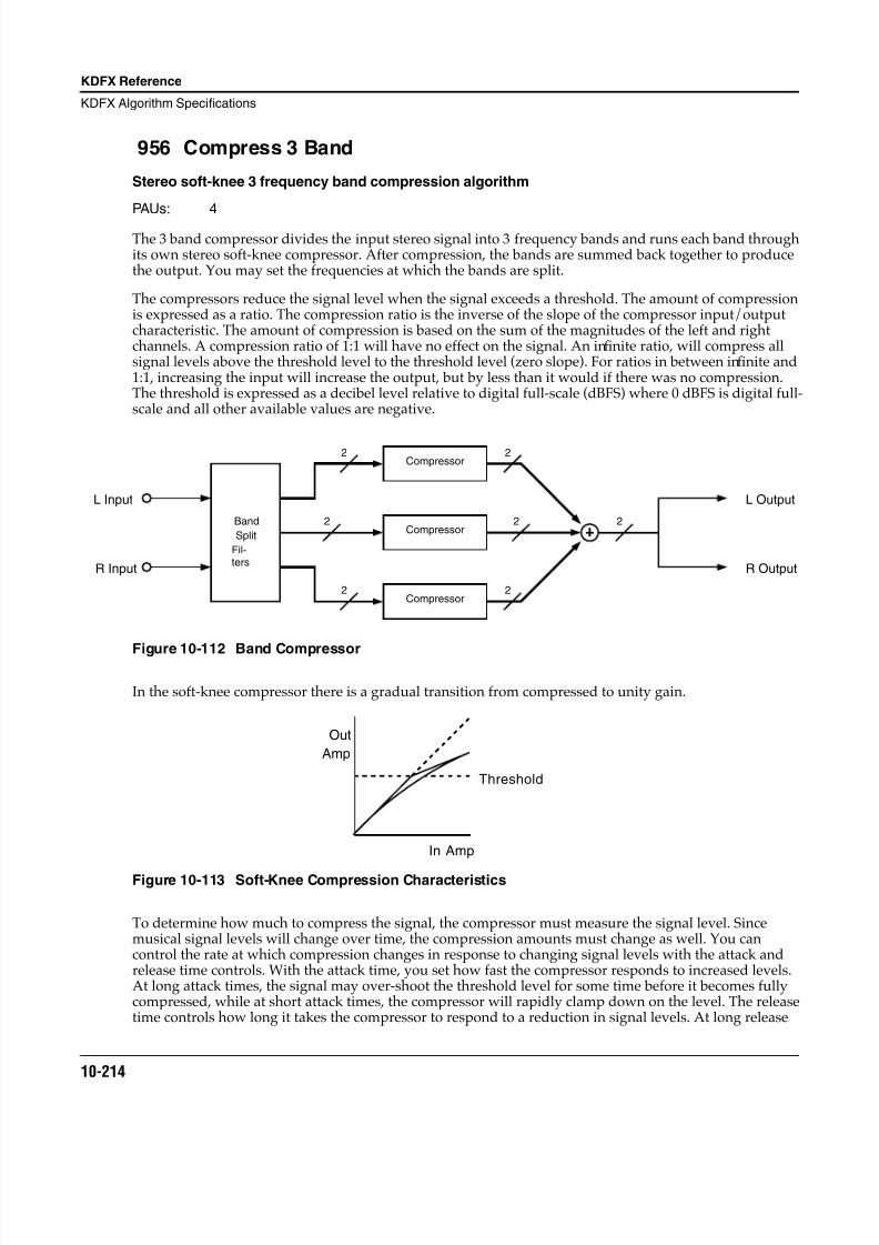
8/21/2019 MR_K2661
http://slidepdf.com/reader/full/mrk2661 296/499
10-214
KDFX Reference
KDFX Algorithm Specifications
956 Compress 3 Band
Stereo soft-knee 3 frequency band compression algorithm
PAUs: 4
The 3 band compressor divides the input stereo signal into 3 frequency bands and runs each band throughits own stereo soft-knee compressor. After compression, the bands are summed back together to producethe output. You may set the frequencies at which the bands are split.
The compressors reduce the signal level when the signal exceeds a threshold. The amount of compressionis expressed as a ratio. The compression ratio is the inverse of the slope of the compressor input/outputcharacteristic. The amount of compression is based on the sum of the magnitudes of the left and rightchannels. A compression ratio of 1:1 will have no effect on the signal. An infinite ratio, will compress allsignal levels above the threshold level to the threshold level (zero slope). For ratios in between infinite and1:1, increasing the input will increase the output, but by less than it would if there was no compression.The threshold is expressed as a decibel level relative to digital full-scale (dBFS) where 0 dBFS is digital full-scale and all other available values are negative.
Figure 10-112 Band Compressor
In the soft-knee compressor there is a gradual transition from compressed to unity gain.
Figure 10-113 Soft-Knee Compression Characteristics
To determine how much to compress the signal, the compressor must measure the signal level. Sincemusical signal levels will change over time, the compression amounts must change as well. You cancontrol the rate at which compression changes in response to changing signal levels with the attack andrelease time controls. With the attack time, you set how fast the compressor responds to increased levels.At long attack times, the signal may over-shoot the threshold level for some time before it becomes fullycompressed, while at short attack times, the compressor will rapidly clamp down on the level. The releasetime controls how long it takes the compressor to respond to a reduction in signal levels. At long release
Band
Split
Fil-ters
Compressor
Compressor
Compressor
L Output
R Output
L Input
R Input
2
2
2
2
2
2
2
Out
Amp
In Amp
Threshold
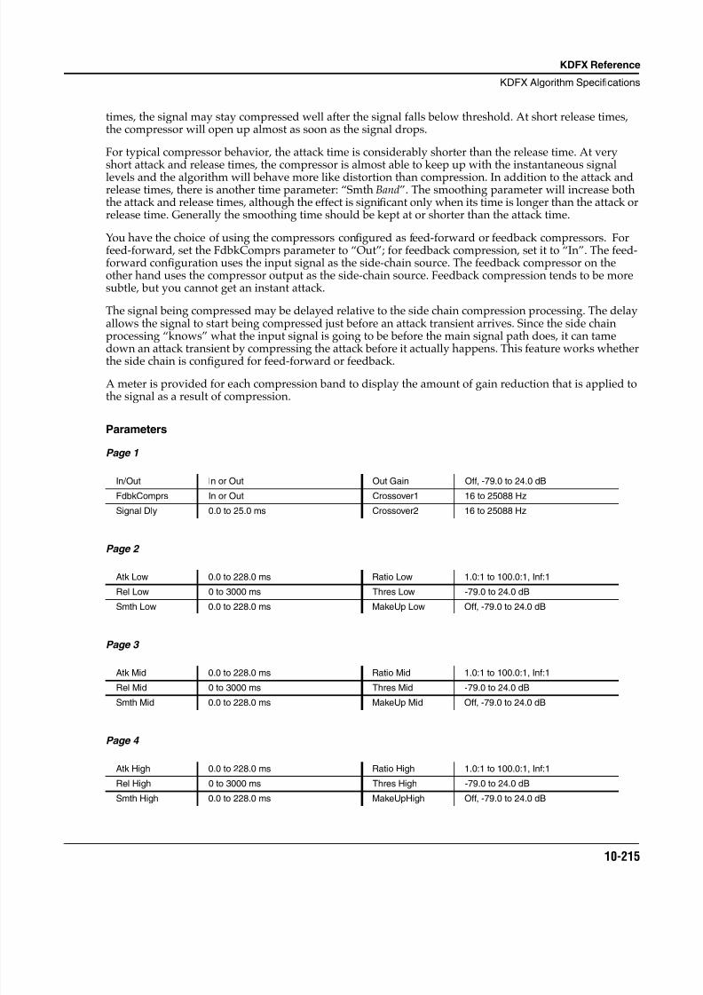
8/21/2019 MR_K2661
http://slidepdf.com/reader/full/mrk2661 297/499
KDFX Reference
KDFX Algorithm Specifications
10-215
times, the signal may stay compressed well after the signal falls below threshold. At short release times,the compressor will open up almost as soon as the signal drops.
For typical compressor behavior, the attack time is considerably shorter than the release time. At veryshort attack and release times, the compressor is almost able to keep up with the instantaneous signallevels and the algorithm will behave more like distortion than compression. In addition to the attack andrelease times, there is another time parameter: “Smth Band”. The smoothing parameter will increase boththe attack and release times, although the effect is significant only when its time is longer than the attack orrelease time. Generally the smoothing time should be kept at or shorter than the attack time.
You have the choice of using the compressors configured as feed-forward or feedback compressors. Forfeed-forward, set the FdbkComprs parameter to “Out”; for feedback compression, set it to “In”. The feed-forward configuration uses the input signal as the side-chain source. The feedback compressor on theother hand uses the compressor output as the side-chain source. Feedback compression tends to be moresubtle, but you cannot get an instant attack.
The signal being compressed may be delayed relative to the side chain compression processing. The delayallows the signal to start being compressed just before an attack transient arrives. Since the side chainprocessing “knows” what the input signal is going to be before the main signal path does, it can tame
down an attack transient by compressing the attack before it actually happens. This feature works whetherthe side chain is configured for feed-forward or feedback.
A meter is provided for each compression band to display the amount of gain reduction that is applied tothe signal as a result of compression.
Parameters
Page 1
Page 2
Page 3
Page 4
In/Out In or Out Out Gain Off, -79.0 to 24.0 dB
FdbkComprs In or Out Crossover1 16 to 25088 Hz
Signal Dly 0.0 to 25.0 ms Crossover2 16 to 25088 Hz
Atk Low 0.0 to 228.0 ms Ratio Low 1.0:1 to 100.0:1, Inf:1
Rel Low 0 to 3000 ms Thres Low -79.0 to 24.0 dB
Smth Low 0.0 to 228.0 ms MakeUp Low Off, -79.0 to 24.0 dB
Atk Mid 0.0 to 228.0 ms Ratio Mid 1.0:1 to 100.0:1, Inf:1
Rel Mid 0 to 3000 ms Thres Mid -79.0 to 24.0 dB
Smth Mid 0.0 to 228.0 ms MakeUp Mid Off, -79.0 to 24.0 dB
Atk High 0.0 to 228.0 ms Ratio High 1.0:1 to 100.0:1, Inf:1
Rel High 0 to 3000 ms Thres High -79.0 to 24.0 dB
Smth High 0.0 to 228.0 ms MakeUpHigh Off, -79.0 to 24.0 dB
8/21/2019 MR_K2661
http://slidepdf.com/reader/full/mrk2661 298/499
10-216
KDFX Reference
KDFX Algorithm Specifications
In/Out When set to “In” the compressor is active; when set to “Out” the compressor is bypassed.
Out Gain Compressing the signal causes a reduction in signal level. To compensate, the output gainparameter may be used to increase the gain by as much as 24 dB. Note that the Out Gainparameter does not control the signal level when the algorithm is set to “Out”.
FdbkComprs A switch to set whether the compressor side chain is configured for feed-forward (Out) orfeedback (In).
Signal Dly The time in ms by which the input signal should be delayed with respect to compressorside chain processing (i.e. side chain pre-delay). This allows the compression to appear totake effect just before the signal actually rises.
Crossover N The Crossover parameters (1 and 2) set the frequencies which divide the threecompression frequency bands. The two parameters are interchangeable, so either maycontain the higher frequency value.
Atk Low, Mid or High. The time for the compressor to start to cut in when there is an increasein signal level (attack) above the threshold.
Rel Low, Mid, and High. The time for the compressor to stop compressing when there is areduction in signal level (release) from a signal level above the threshold.
Smth Low, Mid, and High. A lowpass filter in the control signal path. It is intended to smooththe output of the expander’s envelope detector. Smoothing will affect the attack or releasetimes when the smoothing time is longer than one of the other times.
Ratio Low, Mid, and High. The compression ratio. High ratios are highly compressed; low ratiosare moderately compressed.
Thres Low, Mid, and High. The threshold level in dBFS (decibels relative to full scale) abovewhich the signal begins to be compressed.
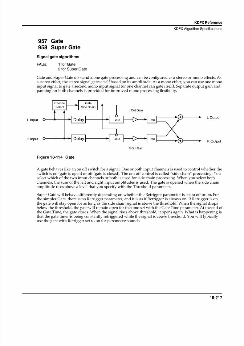
8/21/2019 MR_K2661
http://slidepdf.com/reader/full/mrk2661 299/499
KDFX Reference
KDFX Algorithm Specifications
10-217
957 Gate958 Super Gate
Signal gate algorithms
PAUs: 1 for Gate2 for Super Gate
Gate and Super Gate do stand alone gate processing and can be configured as a stereo or mono effects. Asa stereo effect, the stereo signal gates itself based on its amplitude. As a mono effect, you can use one monoinput signal to gate a second mono input signal (or one channel can gate itself). Separate output gain andpanning for both channels is provided for improved mono processing flexibility.
Figure 10-114 Gate
A gate behaves like an on off switch for a signal. One or both input channels is used to control whether theswitch is on (gate is open) or off (gate is closed). The on/off control is called “side chain” processing. Youselect which of the two input channels or both is used for side chain processing. When you select both
channels, the sum of the left and right input amplitudes is used. The gate is opened when the side chainamplitude rises above a level that you specify with the Threshold parameter.
Super Gate will behave differently depending on whether the Retrigger parameter is set to off or on. Forthe simpler Gate, there is no Retrigger parameter, and it is as if Retrigger is always on. If Retrigger is on,the gate will stay open for as long as the side chain signal is above the threshold. When the signal drops below the threshold, the gate will remain open for the time set with the Gate Time parameter. At the end ofthe Gate Time, the gate closes. When the signal rises above threshold, it opens again. What is happening isthat the gate timer is being constantly retriggered while the signal is above threshold. You will typicallyuse the gate with Retrigger set to on for percussive sounds.
Delay
Delay
Pan
Pan
Channel
Select
Gate
Side Chain
Gate
Gate
L Input
R Input
L Output
R Output
L Out Gain
R Out Gain
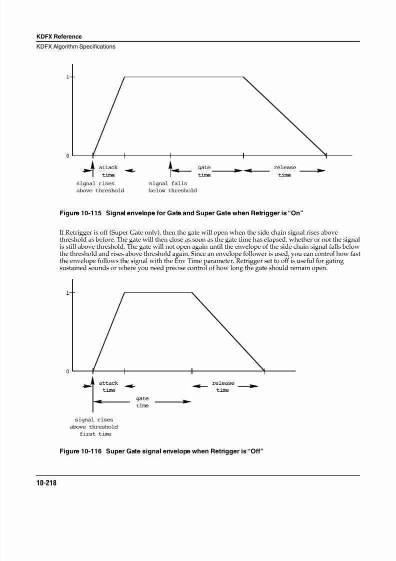
8/21/2019 MR_K2661
http://slidepdf.com/reader/full/mrk2661 300/499
10-218
KDFX Reference
KDFX Algorithm Specifications
Figure 10-115 Signal envelope for Gate and Super Gate when Retrigger is “On”
If Retrigger is off (Super Gate only), then the gate will open when the side chain signal rises abovethreshold as before. The gate will then close as soon as the gate time has elapsed, whether or not the signalis still above threshold. The gate will not open again until the envelope of the side chain signal falls belowthe threshold and rises above threshold again. Since an envelope follower is used, you can control how fastthe envelope follows the signal with the Env Time parameter. Retrigger set to off is useful for gatingsustained sounds or where you need precise control of how long the gate should remain open.
Figure 10-116 Super Gate signal envelope when Retrigger is “Off”
0
1
attack
time
gate
time
release
time
signal rises
above threshold
signal falls
below threshold
0
1
attack
time
gate
time
release
time
signal rises
above threshold
first time
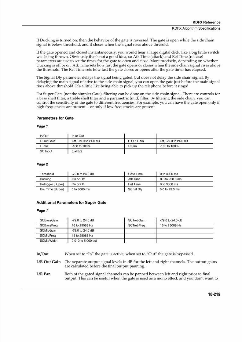
8/21/2019 MR_K2661
http://slidepdf.com/reader/full/mrk2661 301/499
KDFX Reference
KDFX Algorithm Specifications
10-219
If Ducking is turned on, then the behavior of the gate is reversed. The gate is open while the side chainsignal is below threshold, and it closes when the signal rises above thresold.
If the gate opened and closed instantaneously, you would hear a large digital click, like a big knife switchwas being thrown. Obviously that’s not a good idea, so Atk Time (attack) and Rel Time (release)parameters are use to set the times for the gate to open and close. More precisely, depending on whetherDucking is off or on, Atk Time sets how fast the gate opens or closes when the side chain signal rises abovethe threshold. The Rel Time sets how fast the gate closes or opens after the gate timer has elapsed.
The Signal Dly parameter delays the signal being gated, but does not delay the side chain signal. Bydelaying the main signal relative to the side chain signal, you can open the gate just before the main signalrises above threshold. It’s a little like being able to pick up the telephone before it rings!
For Super Gate (not the simpler Gate), filtering can be done on the side chain signal. There are controls fora bass shelf filter, a treble shelf filter and a parametric (mid) filter. By filtering the side chain, you cancontrol the sensitivity of the gate to different frequencies. For example, you can have the gate open only ifhigh frequencies are present -- or only if low frequencies are present.
Parameters for GatePage 1
Page 2
Additional Parameters for Super Gate
Page 1
In/Out When set to “In” the gate is active; when set to “Out” the gate is bypassed.
L/R Out Gain The separate output signal levels in dB for the left and right channels. The output gainsare calculated before the final output panning.
L/R Pan Both of the gated signal channels can be panned between left and right prior to finaloutput. This can be useful when the gate is used as a mono effect, and you don’t want to
In/Out In or Out
L Out Gain Off, -79.0 to 24.0 dB R Out Gain Off, -79.0 to 24.0 dB
L Pan -100 to 100% R Pan -100 to 100%
SC Input (L+R)/2
Threshold -79.0 to 24.0 dB Gate Time 0 to 3000 ms
Ducking On or Off Atk Time 0.0 to 228.0 msRetrigger [Super] On or Off Rel Time 0 to 3000 ms
Env Time [Super] 0 to 3000 ms Signal Dly 0.0 to 25.0 ms
SCBassGain -79.0 to 24.0 dB SCTrebGain -79.0 to 24.0 dB
SCBassFreq 16 to 25088 Hz SCTrebFreq 16 to 25088 Hz
SCMidGain -79.0 to 24.0 dB
SCMidFreq 16 to 25088 Hz
SCMidWidth 0.010 to 5.000 oct
8/21/2019 MR_K2661
http://slidepdf.com/reader/full/mrk2661 302/499
10-220
KDFX Reference
KDFX Algorithm Specifications
hear one of the input channels, but you want your mono output panned to stereo. -100% ispanned to the left, and 100% is panned to the right.
SC Input The side chain input may be the amplitude of the left L input channel, the right R inputchannel, or the sum of the amplitudes of left and right (L+R)/2. You can gate a stereosignal with itself by using the sum, a mono signal with itself, or you can gate a monosignal using a second mono signal as the side chain.
Threshold The signal level in dB required to open the gate (or close the gate if Ducking is on).
Ducking When set to “Off”, the gate opens when the signal rises above threshold and closes whenthe gate time expires. When set to “On”, the gate closes when the signal rises abovethreshold and opens when the gate time expires.
Retrigger If Retrigger is “On”, the gate timer is constantly restarted (retriggered) as long as the sidechain signal is above the threshold. The gate then remains open (assuming Ducking is“Off”) until the signal falls below the threshold and the gate timer has elapsed. IfRetrigger is “Off”, then the gate timer starts at the moment the signal rises above thethreshold and the gate closes after the timer elapses, whether or not the signal is still
above threshold. With Retrigger off, use the Env Time to control how fast the side chainsignal envelope drops below the threshold. With Retrigger set to off, the side chainenvelope must fall below threshold before the gate can open again. [Super Gate only]
Env Time Envelope time is for use when Retrigger is set to “Off”. The envelope time controls thetime for the side chain signal envelope to drop below the threshold. At short times, thegate can reopen rapidly after it has closed, and you may find the gate openingunexpectedly due to an amplitude modulation of the side chain signal. For long times, thegate will remain closed until the envelope has a chance to fall, and you may miss gatingevents.
Gate Time The time in seconds that the gate will stay fully on after the signal envelope rises abovethreshold. The gate timer is started or restarted whenever the signal envelope rises abovethreshold. If Retrigger is On, the gate timer is continually reset while the side chain signal
is above the threshold.Atk Time The time for the gate to ramp from closed to open (reverse if Ducking is on) after the
signal rises above threshold.
Rel Time The time for the gate to ramp from open to closed (reverse if Ducking is on) after the gatetimer has elapsed.
Signal Dly The delay in milliseconds (ms) of the signal to be gated relative to the side chain signal. Bydelaying the main signal, the gate can be opened before the main signal rises above thegating threshold.
Super Gate Parameters
SCBassGain The amount of boost or cut that the side chain bass shelving filter should apply to the low
frequency signals in dB. Every increase of 6 dB approximately doubles the amplitude ofthe signal. Positive values boost the bass signal below the specified frequency. Negativevalues cut the bass signal below the specified frequency.
SCBassFreq The center frequency of the side chain bass shelving filters in intervals of one semitone.
SCTrebGain The amount of boost or cut that the side chain treble shelving filter should apply to thehigh frequency signals in dB. Every increase of 6 dB approximately doubles the amplitudeof the signal. Positive values boost the treble signal above the specified frequency.Negative values cut the treble signal above the specified frequency.
8/21/2019 MR_K2661
http://slidepdf.com/reader/full/mrk2661 303/499
KDFX Reference
KDFX Algorithm Specifications
10-221
SCTrebFreq The center frequency of the side chain treble shelving filters in intervals of one semitone.
SCMidGain The amount of boost or cut that the side chain parametric mid filter should apply in dB tothe specified frequency band. Every increase of 6 dB approximately doubles theamplitude of the signal. Positive values boost the signal at the specified frequency.Negative values cut the signal at the specified frequency.
SCMidFreq The center frequency of the side chain parametric mid filter in intervals of one semitone.The boost or cut will be at a maximum at this frequency.
SCMidWidth The bandwidth of the side chain parametric mid filter may be adjusted. You specify the bandwidth in octaves. Small values result in a very narrow filter response. Large valuesresult in a very broad response.
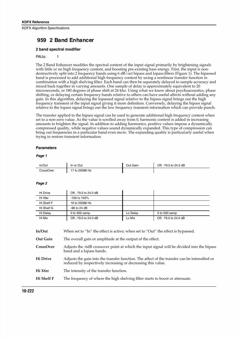
8/21/2019 MR_K2661
http://slidepdf.com/reader/full/mrk2661 304/499
10-222
KDFX Reference
KDFX Algorithm Specifications
959 2 Band Enhancer
2 band spectral modifier
PAUs: 1
The 2 Band Enhancer modifies the spectral content of the input signal primarily by brightening signalswith little or no high frequency content, and boosting pre-existing bass energy. First, the input is non-destructively split into 2 frequency bands using 6 dB/oct hipass and lopass filters (Figure 1). The hipassed band is processed to add additional high frequency content by using a nonlinear transfer function incombination with a high shelving filter. Each band can then be separately delayed to sample accuracy andmixed back together in varying amounts. One sample of delay is approximately equivalent to 20microseconds, or 180 degrees of phase shift at 24 khz. Using what we know about psychoacoustics, phaseshifting, or delaying certain frequency bands relative to others can have useful affects without adding anygain. In this algorithm, delaying the lopassed signal relative to the hipass signal brings out the highfrequency transient of the input signal giving it more definition. Conversely, delaying the hipass signalrelative to the lopass signal brings out the low frequency transient information which can provide punch.
The transfer applied to the hipass signal can be used to generate additional high frequency content whenset to a non-zero value. As the value is scrolled away from 0, harmonic content is added in increasingamounts to brighten the signal. In addition to adding harmonics, positive values impose a dynamicallycompressed quality, while negative values sound dynamically expanded. This type of compression can bring out frequencies in a particular band even more. The expanding quality is particularly useful whentrying to restore transient information.
Parameters
Page 1
Page 2
In/Out When set to “In” the effect is active; when set to “Out” the effect is bypassed.
Out Gain The overall gain or amplitude at the output of the effect.
CrossOver Adjusts the -6dB crossover point at which the input signal will be divided into the hipass band and a lopass bands.
Hi Drive Adjusts the gain into the transfer function. The affect of the transfer can be intensified orreduced by respectively increasing or decreasing this value.
Hi Xfer The intensity of the transfer function.
Hi Shelf F The frequency of where the high shelving filter starts to boost or attenuate.
In/Out In or Out Out Gain Off, -79.0 to 24.0 dB
CrossOver 17 to 25088 Hz
Hi Drive Off, -79.0 to 24.0 dB
Hi Xfer -100 to 100%
Hi Shelf F 16 to 25088 Hz
Hi Shelf G -96 to 24 dB
Hi Delay 0 to 500 samp Lo Delay 0 to 500 samp
Hi Mix Off, -79.0 to 24.0 dB Lo Mix Off, -79.0 to 24.0 dB
8/21/2019 MR_K2661
http://slidepdf.com/reader/full/mrk2661 305/499
KDFX Reference
KDFX Algorithm Specifications
10-223
Hi Shelf G The boost or cut of the high shelving filter.
Hi Delay Adjusts the number of samples the hipass signal is delayed.
Hi Mix Adjusts the output gain of the hipass signal.
Lo Delay Adjusts the number of samples the lopass signal is delayed.
Lo Mix Adjusts the output gain of the lopass signal.
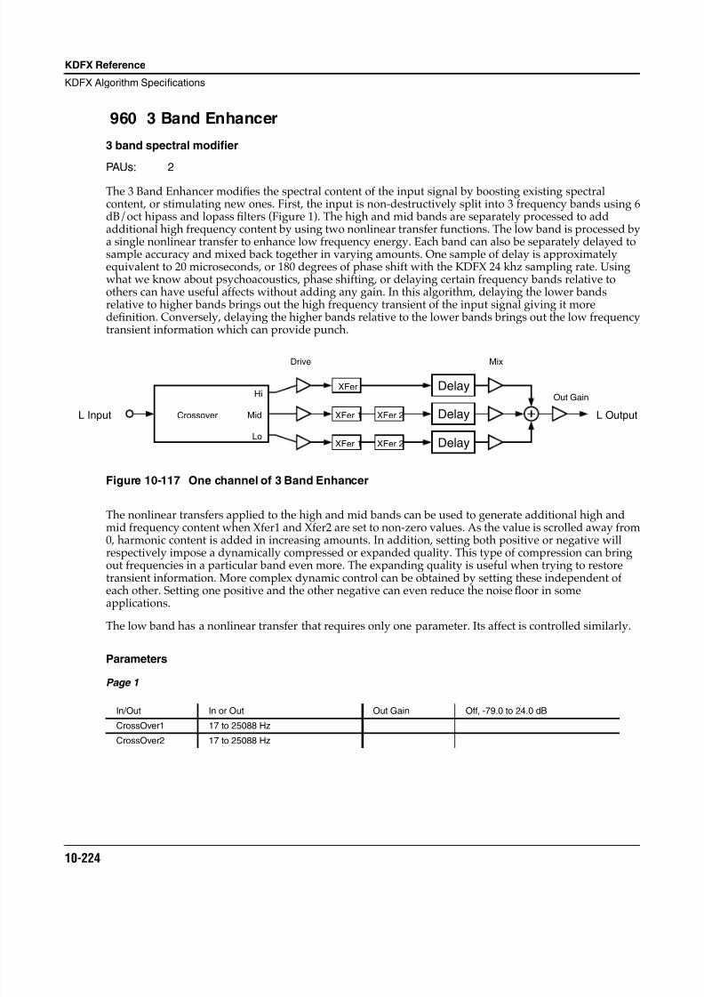
8/21/2019 MR_K2661
http://slidepdf.com/reader/full/mrk2661 306/499
10-224
KDFX Reference
KDFX Algorithm Specifications
960 3 Band Enhancer
3 band spectral modifier
PAUs: 2
The 3 Band Enhancer modifies the spectral content of the input signal by boosting existing spectralcontent, or stimulating new ones. First, the input is non-destructively split into 3 frequency bands using 6dB/oct hipass and lopass filters (Figure 1). The high and mid bands are separately processed to addadditional high frequency content by using two nonlinear transfer functions. The low band is processed bya single nonlinear transfer to enhance low frequency energy. Each band can also be separately delayed tosample accuracy and mixed back together in varying amounts. One sample of delay is approximatelyequivalent to 20 microseconds, or 180 degrees of phase shift with the KDFX 24 khz sampling rate. Usingwhat we know about psychoacoustics, phase shifting, or delaying certain frequency bands relative toothers can have useful affects without adding any gain. In this algorithm, delaying the lower bandsrelative to higher bands brings out the high frequency transient of the input signal giving it moredefinition. Conversely, delaying the higher bands relative to the lower bands brings out the low frequencytransient information which can provide punch.
Figure 10-117 One channel of 3 Band Enhancer
The nonlinear transfers applied to the high and mid bands can be used to generate additional high andmid frequency content when Xfer1 and Xfer2 are set to non-zero values. As the value is scrolled away from0, harmonic content is added in increasing amounts. In addition, setting both positive or negative willrespectively impose a dynamically compressed or expanded quality. This type of compression can bringout frequencies in a particular band even more. The expanding quality is useful when trying to restoretransient information. More complex dynamic control can be obtained by setting these independent ofeach other. Setting one positive and the other negative can even reduce the noise floor in someapplications.
The low band has a nonlinear transfer that requires only one parameter. Its affect is controlled similarly.
Parameters
Page 1
In/Out In or Out Out Gain Off, -79.0 to 24.0 dB
CrossOver1 17 to 25088 Hz
CrossOver2 17 to 25088 Hz
Crossover
Hi
Mid
Lo
XFer
XFer 1
XFer 1
XFer 2
XFer 2
Delay
Delay
Delay
L Input L Output
Drive Mix
Out Gain
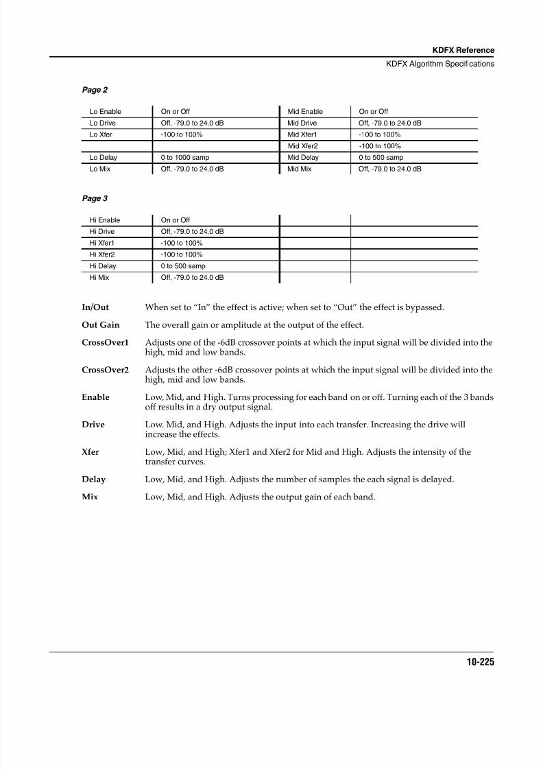
8/21/2019 MR_K2661
http://slidepdf.com/reader/full/mrk2661 307/499
KDFX Reference
KDFX Algorithm Specifications
10-225
Page 2
Page 3
In/Out When set to “In” the effect is active; when set to “Out” the effect is bypassed.
Out Gain The overall gain or amplitude at the output of the effect.
CrossOver1 Adjusts one of the -6dB crossover points at which the input signal will be divided into thehigh, mid and low bands.
CrossOver2 Adjusts the other -6dB crossover points at which the input signal will be divided into thehigh, mid and low bands.
Enable Low, Mid, and High. Turns processing for each band on or off. Turning each of the 3 bandsoff results in a dry output signal.
Drive Low. Mid, and High. Adjusts the input into each transfer. Increasing the drive willincrease the effects.
Xfer Low, Mid, and High; Xfer1 and Xfer2 for Mid and High. Adjusts the intensity of thetransfer curves.
Delay Low, Mid, and High. Adjusts the number of samples the each signal is delayed.
Mix Low, Mid, and High. Adjusts the output gain of each band.
Lo Enable On or Off Mid Enable On or Off
Lo Drive Off, -79.0 to 24.0 dB Mid Drive Off, -79.0 to 24.0 dB
Lo Xfer -100 to 100% Mid Xfer1 -100 to 100%Mid Xfer2 -100 to 100%
Lo Delay 0 to 1000 samp Mid Delay 0 to 500 samp
Lo Mix Off, -79.0 to 24.0 dB Mid Mix Off, -79.0 to 24.0 dB
Hi Enable On or Off
Hi Drive Off, -79.0 to 24.0 dB
Hi Xfer1 -100 to 100%
Hi Xfer2 -100 to 100%
Hi Delay 0 to 500 sampHi Mix Off, -79.0 to 24.0 dB
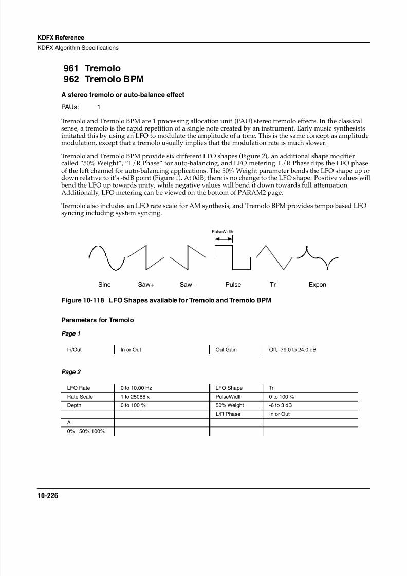
8/21/2019 MR_K2661
http://slidepdf.com/reader/full/mrk2661 308/499
10-226
KDFX Reference
KDFX Algorithm Specifications
961 Tremolo962 Tremolo BPM
A stereo tremolo or auto-balance effect
PAUs: 1
Tremolo and Tremolo BPM are 1 processing allocation unit (PAU) stereo tremolo effects. In the classicalsense, a tremolo is the rapid repetition of a single note created by an instrument. Early music synthesistsimitated this by using an LFO to modulate the amplitude of a tone. This is the same concept as amplitudemodulation, except that a tremolo usually implies that the modulation rate is much slower.
Tremolo and Tremolo BPM provide six different LFO shapes (Figure 2), an additional shape modifiercalled “50% Weight”, “L/R Phase” for auto-balancing, and LFO metering. L/R Phase flips the LFO phaseof the left channel for auto-balancing applications. The 50% Weight parameter bends the LFO shape up ordown relative to it’s -6dB point (Figure 1). At 0dB, there is no change to the LFO shape. Positive values will bend the LFO up towards unity, while negative values will bend it down towards full attenuation.Additionally, LFO metering can be viewed on the bottom of PARAM2 page.
Tremolo also includes an LFO rate scale for AM synthesis, and Tremolo BPM provides tempo based LFOsyncing including system syncing.
Figure 10-118 LFO Shapes available for Tremolo and Tremolo BPM
Parameters for Tremolo
Page 1
Page 2
In/Out In or Out Out Gain Off, -79.0 to 24.0 dB
LFO Rate 0 to 10.00 Hz LFO Shape Tri
Rate Scale 1 to 25088 x PulseWidth 0 to 100 %
Depth 0 to 100 % 50% Weight -6 to 3 dB
L/R Phase In or Out
A
0% 50% 100%
Sine Saw+ Saw- Pulse Tri Expon
PulseWidth
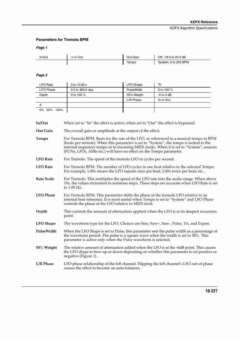
8/21/2019 MR_K2661
http://slidepdf.com/reader/full/mrk2661 309/499
KDFX Reference
KDFX Algorithm Specifications
10-227
Parameters for Tremolo BPM
Page 1
Page 2
In/Out When set to “In” the effect is active; when set to “Out” the effect is bypassed.
Out Gain The overall gain or amplitude at the output of the effect.
Tempo For Tremolo BPM. Basis for the rate of the LFO, as referenced to a musical tempo in BPM(beats per minute). When this parameter is set to “System”, the tempo is locked to theinternal sequencer tempo or to incoming MIDI clocks. When it is set to “System”, sources(FUNs, LFOs, ASRs etc.) will have no effect on the Tempo parameter.
LFO Rate For Tremolo. The speed of the tremolo LFO in cycles per second.
LFO Rate For Tremolo BPM. The number of LFO cycles in one beat relative to the selected Tempo.For example, 1.00x means the LFO repeats once per beat; 2.00x twice per beat; etc...
Rate Scale For Tremolo. This multiplies the speed of the LFO rate into the audio range. When above19x, the values increment in semitone steps. These steps are accurate when LFO Rate is setto 1.00 Hz.
LFO Phase For Tremolo BPM. This parameter shifts the phase of the tremolo LFO relative to aninternal beat reference. It is most useful when Tempo is set to “System” and LFO Phasecontrols the phase of the LFO relative to MIDI clock.
Depth This controls the amount of attenuation applied when the LFO is at its deepest excursionpoint.
LFO Shape The waveform type for the LFO. Choices are Sine, Saw+, Saw-, Pulse, Tri, and Expon.
PulseWidth When the LFO Shape is set to Pulse, this parameter sets the pulse width as a percentage of
the waveform period. The pulse is a square wave when the width is set to 50%. Thisparameter is active only when the Pulse waveform is selected.
50% Weight The relative amount of attenuation added when the LFO is at the -6dB point. This causesthe LFO shape to bow up or down depending on whether this parameter is set positive ornegative (Figure 1).
L/R Phase LFO phase relationship of the left channel. Flipping the left channel’s LFO out of phasecauses the effect to become an auto-balancer.
In/Out In or Out Out Gain Off, -79.0 to 24.0 dB
Tempo System, 0 to 255 BPM
LFO Rate 0 to 12.00 x LFO Shape Tri
LFO Phase 0.0 to 360.0 deg PulseWidth 0 to 100 %
Depth 0 to 100 % 50% Weight -6 to 3 dB
L/R Phase In or Out
A
0% 50% 100%
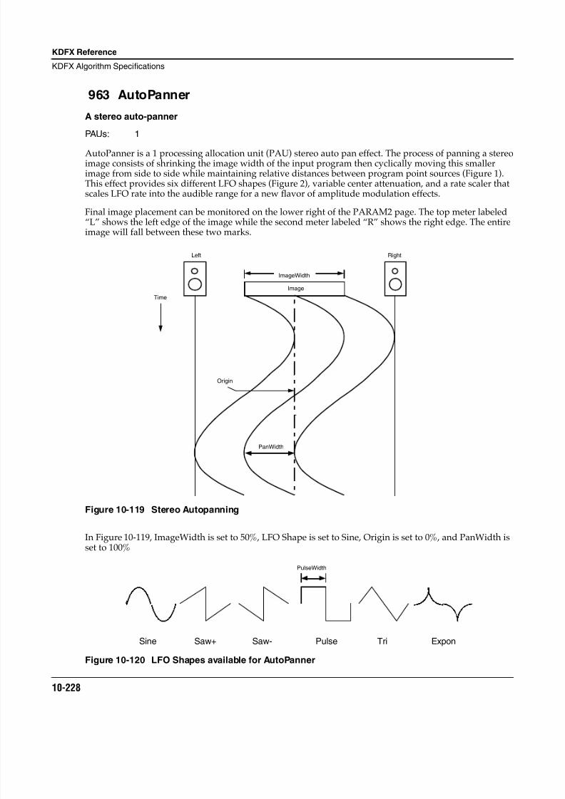
8/21/2019 MR_K2661
http://slidepdf.com/reader/full/mrk2661 310/499
10-228
KDFX Reference
KDFX Algorithm Specifications
963 AutoPanner
A stereo auto-panner
PAUs: 1
AutoPanner is a 1 processing allocation unit (PAU) stereo auto pan effect. The process of panning a stereoimage consists of shrinking the image width of the input program then cyclically moving this smallerimage from side to side while maintaining relative distances between program point sources (Figure 1).This effect provides six different LFO shapes (Figure 2), variable center attenuation, and a rate scaler thatscales LFO rate into the audible range for a new flavor of amplitude modulation effects.
Final image placement can be monitored on the lower right of the PARAM2 page. The top meter labeled“L” shows the left edge of the image while the second meter labeled “R” shows the right edge. The entireimage will fall between these two marks.
Figure 10-119 Stereo Autopanning
In Figure 10-119, ImageWidth is set to 50%, LFO Shape is set to Sine, Origin is set to 0%, and PanWidth isset to 100%
Figure 10-120 LFO Shapes available for AutoPanner
Origin
Image
PanWidth
ImageWidth
Left Right
Time
Sine Saw+ Saw- Pulse Tri Expon
PulseWidth
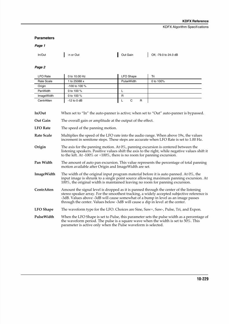
8/21/2019 MR_K2661
http://slidepdf.com/reader/full/mrk2661 311/499
KDFX Reference
KDFX Algorithm Specifications
10-229
Parameters
Page 1
Page 2
In/Out When set to “In” the auto-panner is active; when set to “Out” auto-panner is bypassed.
Out Gain The overall gain or amplitude at the output of the effect.
LFO Rate The speed of the panning motion.
Rate Scale Multiplies the speed of the LFO rate into the audio range. When above 19x, the valuesincrement in semitone steps. These steps are accurate when LFO Rate is set to 1.00 Hz.
Origin The axis for the panning motion. At 0%, panning excursion is centered between thelistening speakers. Positive values shift the axis to the right, while negative values shift itto the left. At -100% or +100%, there is no room for panning excursion.
Pan Width The amount of auto pan excursion. This value represents the percentage of total panningmotion available after Origin and ImageWidth are set.
ImageWidth The width of the original input program material before it is auto panned. At 0%, theinput image is shrunk to a single point source allowing maximum panning excursion. At100%, the original width is maintained leaving no room for panning excursion.
CentrAtten Amount the signal level is dropped as it is panned through the center of the listeningstereo speaker array. For the smoothest tracking, a widely accepted subjective reference is-3dB. Values above -3dB will cause somewhat of a bump in level as an image passesthrough the center. Values below -3dB will cause a dip in level at the center.
LFO Shape The waveform type for the LFO. Choices are Sine, Saw+, Saw-, Pulse, Tri, and Expon.
PulseWidth When the LFO Shape is set to Pulse, this parameter sets the pulse width as a percentage ofthe waveform period. The pulse is a square wave when the width is set to 50%. This
parameter is active only when the Pulse waveform is selected.
In/Out In or Out Out Gain Off, -79.0 to 24.0 dB
LFO Rate 0 to 10.00 Hz LFO Shape Tri
Rate Scale 1 to 25088 x PulseWidth 0 to 100%
Origin -100 to 100 %
PanWidth 0 to 100 % L
ImageWidth 0 to 100 % R
CentrAtten -12 to 0 dB L C R
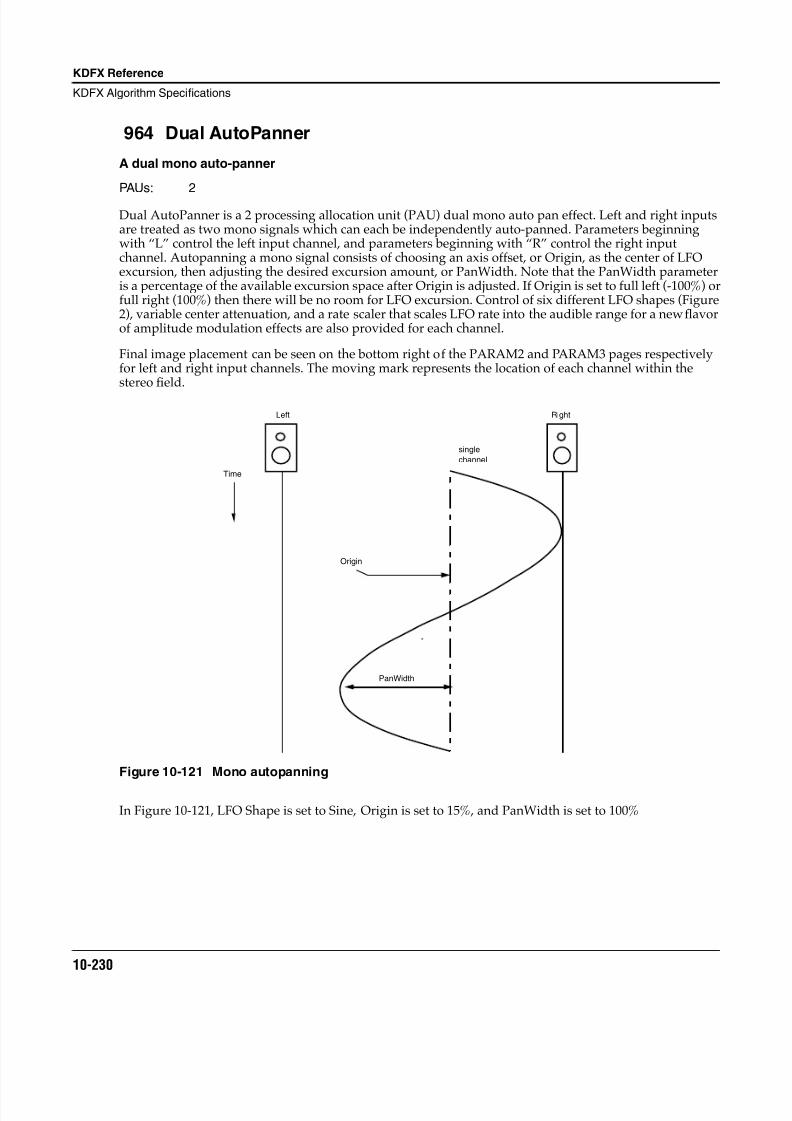
8/21/2019 MR_K2661
http://slidepdf.com/reader/full/mrk2661 312/499
10-230
KDFX Reference
KDFX Algorithm Specifications
964 Dual AutoPanner
A dual mono auto-panner
PAUs: 2
Dual AutoPanner is a 2 processing allocation unit (PAU) dual mono auto pan effect. Left and right inputsare treated as two mono signals which can each be independently auto-panned. Parameters beginningwith “L” control the left input channel, and parameters beginning with “R” control the right inputchannel. Autopanning a mono signal consists of choosing an axis offset, or Origin, as the center of LFOexcursion, then adjusting the desired excursion amount, or PanWidth. Note that the PanWidth parameteris a percentage of the available excursion space after Origin is adjusted. If Origin is set to full left (-100%) orfull right (100%) then there will be no room for LFO excursion. Control of six different LFO shapes (Figure2), variable center attenuation, and a rate scaler that scales LFO rate into the audible range for a new flavorof amplitude modulation effects are also provided for each channel.
Final image placement can be seen on the bottom right of the PARAM2 and PARAM3 pages respectivelyfor left and right input channels. The moving mark represents the location of each channel within thestereo field.
Figure 10-121 Mono autopanning
In Figure 10-121 , LFO Shape is set to Sine, Origin is set to 15%, and PanWidth is set to 100%
PanWidth
Origin
Left Right
Time
single
channel
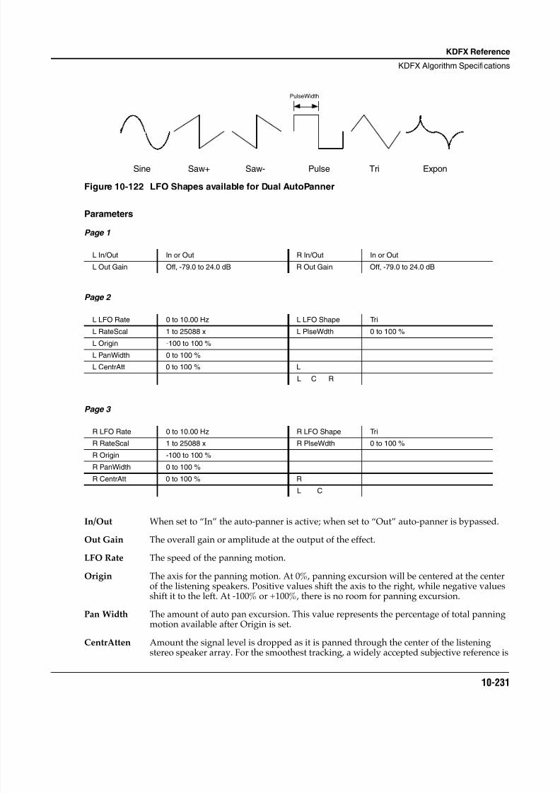
8/21/2019 MR_K2661
http://slidepdf.com/reader/full/mrk2661 313/499
KDFX Reference
KDFX Algorithm Specifications
10-231
Figure 10-122 LFO Shapes available for Dual AutoPanner
Parameters
Page 1
Page 2
Page 3
In/Out When set to “In” the auto-panner is active; when set to “Out” auto-panner is bypassed.
Out Gain The overall gain or amplitude at the output of the effect.
LFO Rate The speed of the panning motion.
Origin The axis for the panning motion. At 0%, panning excursion will be centered at the centerof the listening speakers. Positive values shift the axis to the right, while negative valuesshift it to the left. At -100% or +100%, there is no room for panning excursion.
Pan Width The amount of auto pan excursion. This value represents the percentage of total panningmotion available after Origin is set.
CentrAtten Amount the signal level is dropped as it is panned through the center of the listeningstereo speaker array. For the smoothest tracking, a widely accepted subjective reference is
L In/Out In or Out R In/Out In or Out
L Out Gain Off, -79.0 to 24.0 dB R Out Gain Off, -79.0 to 24.0 dB
L LFO Rate 0 to 10.00 Hz L LFO Shape Tri
L RateScal 1 to 25088 x L PlseWdth 0 to 100 %
L Origin -100 to 100 %
L PanWidth 0 to 100 %
L CentrAtt 0 to 100 % L
L C R
R LFO Rate 0 to 10.00 Hz R LFO Shape Tri
R RateScal 1 to 25088 x R PlseWdth 0 to 100 %
R Origin -100 to 100 %
R PanWidth 0 to 100 %
R CentrAtt 0 to 100 % R
L C
Sine Saw+ Saw- Pulse Tri Expon
PulseWidth

8/21/2019 MR_K2661
http://slidepdf.com/reader/full/mrk2661 314/499
10-232
KDFX Reference
KDFX Algorithm Specifications
-3dB. Values above -3dB will cause somewhat of a bump in level as an image passesthrough the center. Values below -3dB will cause a dip in level at the center.
LFO Shape The waveform type for the LFO. Choices are Sine, Saw+, Saw-, Pulse, Tri, and Expon.
PulseWidth When the LFO Shape is set to Pulse, this parameter sets the pulse width as a percentage ofthe waveform period. The pulse is a square wave when the width is set to 50%. Thisparameter is active only when the Pulse waveform is selected.
8/21/2019 MR_K2661
http://slidepdf.com/reader/full/mrk2661 315/499
KDFX Reference
KDFX Algorithm Specifications
10-233
965 SRS
Licenced Sound Retrieval System ® or SRSTM effect
PAUs: 1
The SRS TM algorithm has been licenced from SRS Labs, Inc. The following is from an SRS Labs pressrelease:
SRS, the Sound Retrieval System, is based on the human hearing system. It produces a fully immersive,three-dimensional sound image from any audio source with two or more standard stereo speakers.Whether the signal is mono, stereo, surround sound or encoded with any other audio enhancementtechnology, SRS expands the material and creates a realistic, panoramic sound experience with no “sweetspot” or centered listening position. SRS is single-ended, requiring no encoding or decoding, and uses noartificial signal manipulation such as time delay or phase shift to produce its natural, true-to-life soundimage.
The four SRS parameters control the ambience of the image, and may have different optimal settingsdepending on the amount of stereo content in the inputs. To match the optimal settings specified by SRSLabs, the bass and treble gains should be set to 0 dB. This algorithm will have no effect on mono signals.
Parameters
Page 1
In/Out When set to “In” the effect is active; when set to “Out” the effect is bypassed.
Out Gain The overall gain or amplitude at the output of the effect. Out Gain is not applied to thesignal when the effect is bypassed.
Center The amount of “center channel” can be varied with this control.
Space The width of the image is controlled with this parameter.
Bass Gain The amount of ambience added to the Bass frequencies in the signals. A setting of 0 dBgives a best match to the optimizations of SRS Labs.
Treb Gain The amount of ambience added to the Treble frequencies in the signal. A setting of 0 dBgives a best match to the optimizations of SRS Labs.
In/Out In or Out Out Gain Off, -79.0 to 24.0 dB
Center Off, -79.0 to 24.0 dB Bass Gain -79.0 to 24.0 dB
Space Off, -79.0 to 24.0 dB Treb Gain -79.0 to 24.0 dB
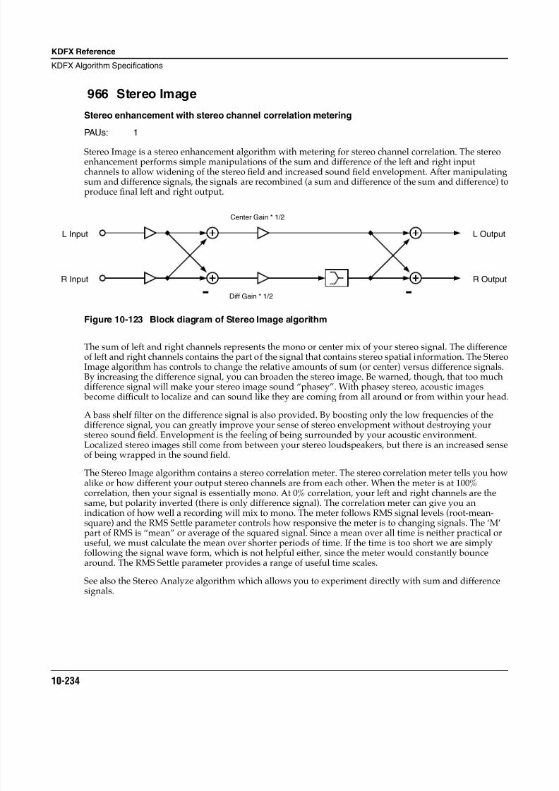
8/21/2019 MR_K2661
http://slidepdf.com/reader/full/mrk2661 316/499
10-234
KDFX Reference
KDFX Algorithm Specifications
966 Stereo Image
Stereo enhancement with stereo channel correlation metering
PAUs: 1
Stereo Image is a stereo enhancement algorithm with metering for stereo channel correlation. The stereoenhancement performs simple manipulations of the sum and difference of the left and right inputchannels to allow widening of the stereo field and increased sound field envelopment. After manipulatingsum and difference signals, the signals are recombined (a sum and difference of the sum and difference) toproduce final left and right output.
Figure 10-123 Block diagram of Stereo Image algorithm
The sum of left and right channels represents the mono or center mix of your stereo signal. The differenceof left and right channels contains the part of the signal that contains stereo spatial information. The StereoImage algorithm has controls to change the relative amounts of sum (or center) versus difference signals.By increasing the difference signal, you can broaden the stereo image. Be warned, though, that too muchdifference signal will make your stereo image sound “phasey”. With phasey stereo, acoustic images become dif ficult to localize and can sound like they are coming from all around or from within your head.
A bass shelf filter on the difference signal is also provided. By boosting only the low frequencies of thedifference signal, you can greatly improve your sense of stereo envelopment without destroying yourstereo sound field. Envelopment is the feeling of being surrounded by your acoustic environment.Localized stereo images still come from between your stereo loudspeakers, but there is an increased senseof being wrapped in the sound field.
The Stereo Image algorithm contains a stereo correlation meter. The stereo correlation meter tells you howalike or how different your output stereo channels are from each other. When the meter is at 100%correlation, then your signal is essentially mono. At 0% correlation, your left and right channels are thesame, but polarity inverted (there is only difference signal). The correlation meter can give you anindication of how well a recording will mix to mono. The meter follows RMS signal levels (root-mean-square) and the RMS Settle parameter controls how responsive the meter is to changing signals. The ‘M’part of RMS is “mean” or average of the squared signal. Since a mean over all time is neither practical oruseful, we must calculate the mean over shorter periods of time. If the time is too short we are simply
following the signal wave form, which is not helpful either, since the meter would constantly bouncearound. The RMS Settle parameter provides a range of useful time scales.
See also the Stereo Analyze algorithm which allows you to experiment directly with sum and differencesignals.
L Output
R Output
L Input
R Input
Center Gain * 1/2
Diff Gain * 1/2- -
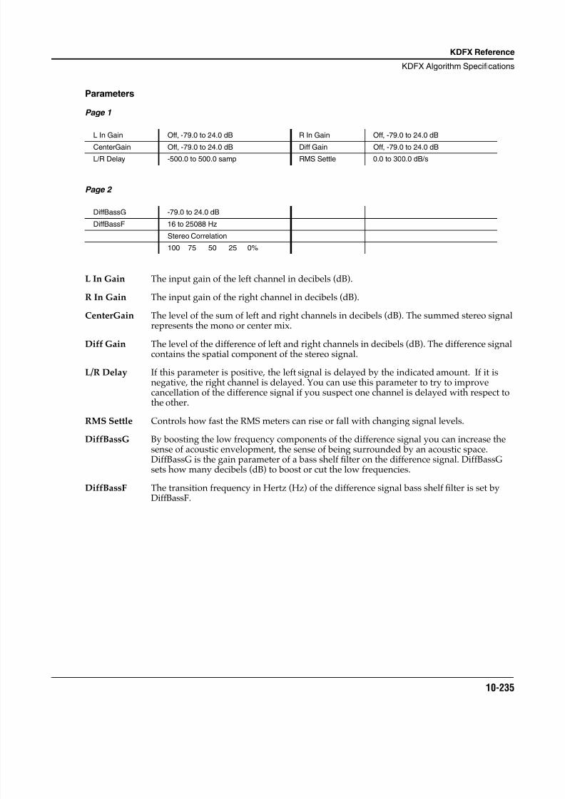
8/21/2019 MR_K2661
http://slidepdf.com/reader/full/mrk2661 317/499
KDFX Reference
KDFX Algorithm Specifications
10-235
Parameters
Page 1
Page 2
L In Gain The input gain of the left channel in decibels (dB).
R In Gain The input gain of the right channel in decibels (dB).
CenterGain The level of the sum of left and right channels in decibels (dB). The summed stereo signalrepresents the mono or center mix.
Diff Gain The level of the difference of left and right channels in decibels (dB). The difference signalcontains the spatial component of the stereo signal.
L/R Delay If this parameter is positive, the left signal is delayed by the indicated amount. If it isnegative, the right channel is delayed. You can use this parameter to try to improvecancellation of the difference signal if you suspect one channel is delayed with respect tothe other.
RMS Settle Controls how fast the RMS meters can rise or fall with changing signal levels.
DiffBassG By boosting the low frequency components of the difference signal you can increase thesense of acoustic envelopment, the sense of being surrounded by an acoustic space.DiffBassG is the gain parameter of a bass shelf filter on the difference signal. DiffBassGsets how many decibels (dB) to boost or cut the low frequencies.
DiffBassF The transition frequency in Hertz (Hz) of the difference signal bass shelf filter is set byDiffBassF.
L In Gain Off, -79.0 to 24.0 dB R In Gain Off, -79.0 to 24.0 dB
CenterGain Off, -79.0 to 24.0 dB Diff Gain Off, -79.0 to 24.0 dB
L/R Delay -500.0 to 500.0 samp RMS Settle 0.0 to 300.0 dB/s
DiffBassG -79.0 to 24.0 dB
DiffBassF 16 to 25088 Hz
Stereo Correlation
100 75 50 25 0%
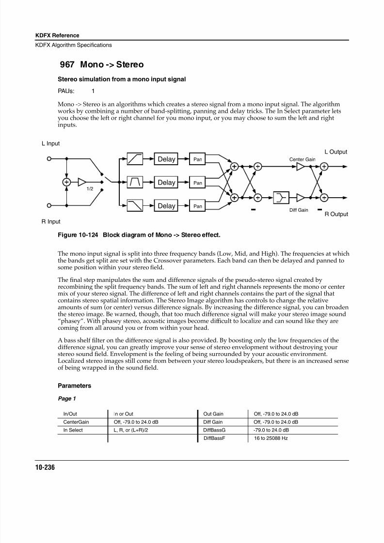
8/21/2019 MR_K2661
http://slidepdf.com/reader/full/mrk2661 318/499
10-236
KDFX Reference
KDFX Algorithm Specifications
967 Mono -> Stereo
Stereo simulation from a mono input signal
PAUs: 1
Mono -> Stereo is an algorithms which creates a stereo signal from a mono input signal. The algorithmworks by combining a number of band-splitting, panning and delay tricks. The In Select parameter letsyou choose the left or right channel for you mono input, or you may choose to sum the left and rightinputs.
Figure 10-124 Block diagram of Mono -> Stereo effect.
The mono input signal is split into three frequency bands (Low, Mid, and High). The frequencies at whichthe bands get split are set with the Crossover parameters. Each band can then be delayed and panned tosome position within your stereo field.
The final step manipulates the sum and difference signals of the pseudo-stereo signal created by
recombining the split frequency bands. The sum of left and right channels represents the mono or centermix of your stereo signal. The difference of left and right channels contains the part of the signal thatcontains stereo spatial information. The Stereo Image algorithm has controls to change the relativeamounts of sum (or center) versus difference signals. By increasing the difference signal, you can broadenthe stereo image. Be warned, though, that too much difference signal will make your stereo image sound“phasey”. With phasey stereo, acoustic images become dif ficult to localize and can sound like they arecoming from all around you or from within your head.
A bass shelf filter on the difference signal is also provided. By boosting only the low frequencies of thedifference signal, you can greatly improve your sense of stereo envelopment without destroying yourstereo sound field. Envelopment is the feeling of being surrounded by your acoustic environment.Localized stereo images still come from between your stereo loudspeakers, but there is an increased senseof being wrapped in the sound field.
Parameters
Page 1
In/Out In or Out Out Gain Off, -79.0 to 24.0 dB
CenterGain Off, -79.0 to 24.0 dB Diff Gain Off, -79.0 to 24.0 dB
In Select L, R, or (L+R)/2 DiffBassG -79.0 to 24.0 dB
DiffBassF 16 to 25088 Hz
Delay
Delay
Delay
Pan
Pan
Pan
L Input
R Input
L Output
R Output--
Center Gain
Diff Gain
1/2
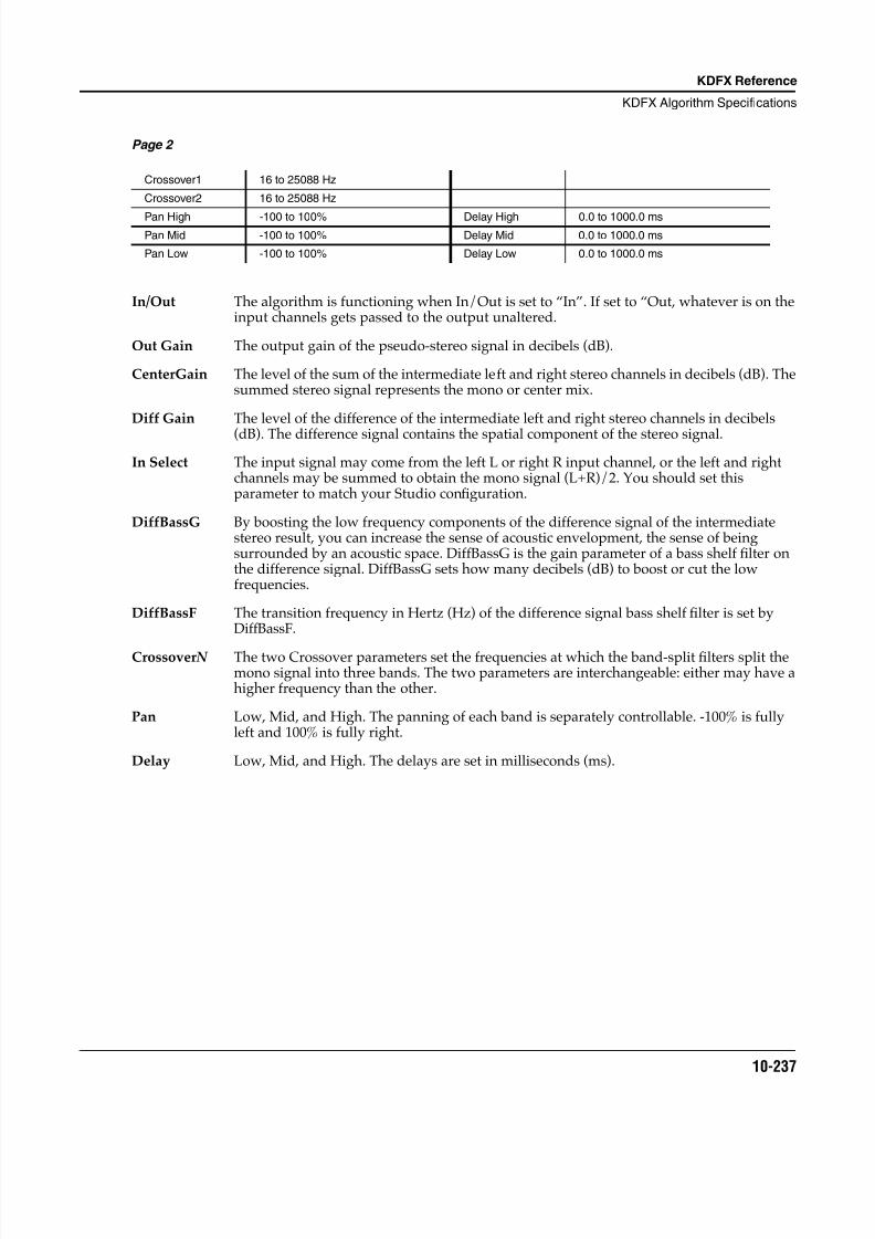
8/21/2019 MR_K2661
http://slidepdf.com/reader/full/mrk2661 319/499
KDFX Reference
KDFX Algorithm Specifications
10-237
Page 2
In/Out The algorithm is functioning when In/Out is set to “In”. If set to “Out, whatever is on theinput channels gets passed to the output unaltered.
Out Gain The output gain of the pseudo-stereo signal in decibels (dB).
CenterGain The level of the sum of the intermediate left and right stereo channels in decibels (dB). Thesummed stereo signal represents the mono or center mix.
Diff Gain The level of the difference of the intermediate left and right stereo channels in decibels
(dB). The difference signal contains the spatial component of the stereo signal.
In Select The input signal may come from the left L or right R input channel, or the left and rightchannels may be summed to obtain the mono signal (L+R)/2. You should set thisparameter to match your Studio configuration.
DiffBassG By boosting the low frequency components of the difference signal of the intermediatestereo result, you can increase the sense of acoustic envelopment, the sense of beingsurrounded by an acoustic space. DiffBassG is the gain parameter of a bass shelf filter onthe difference signal. DiffBassG sets how many decibels (dB) to boost or cut the lowfrequencies.
DiffBassF The transition frequency in Hertz (Hz) of the difference signal bass shelf filter is set byDiffBassF.
Crossover N The two Crossover parameters set the frequencies at which the band-split filters split themono signal into three bands. The two parameters are interchangeable: either may have ahigher frequency than the other.
Pan Low, Mid, and High. The panning of each band is separately controllable. -100% is fullyleft and 100% is fully right.
Delay Low, Mid, and High. The delays are set in milliseconds (ms).
Crossover1 16 to 25088 Hz
Crossover2 16 to 25088 Hz
Pan High -100 to 100% Delay High 0.0 to 1000.0 msPan Mid -100 to 100% Delay Mid 0.0 to 1000.0 ms
Pan Low -100 to 100% Delay Low 0.0 to 1000.0 ms
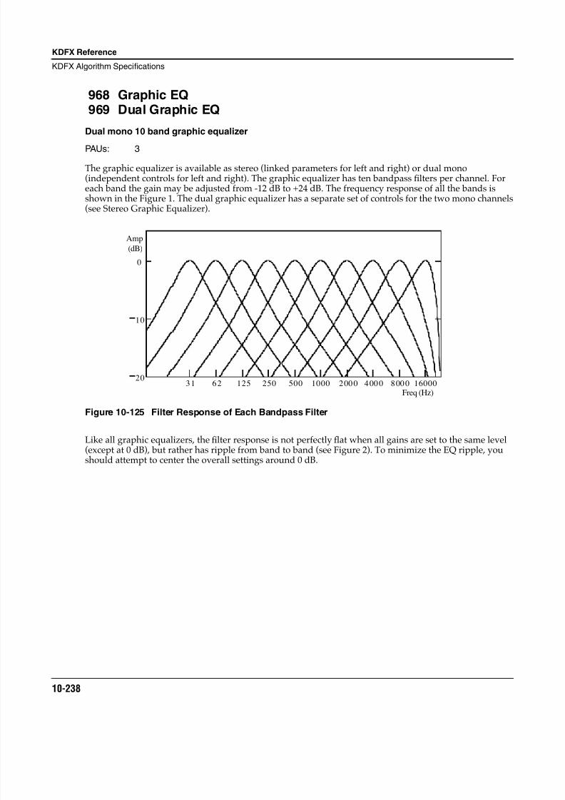
8/21/2019 MR_K2661
http://slidepdf.com/reader/full/mrk2661 320/499
10-238
KDFX Reference
KDFX Algorithm Specifications
968 Graphic EQ969 Dual Graphic EQ
Dual mono 10 band graphic equalizer
PAUs: 3
The graphic equalizer is available as stereo (linked parameters for left and right) or dual mono(independent controls for left and right). The graphic equalizer has ten bandpass filters per channel. Foreach band the gain may be adjusted from -12 dB to +24 dB. The frequency response of all the bands isshown in the Figure 1. The dual graphic equalizer has a separate set of controls for the two mono channels(see Stereo Graphic Equalizer).
Figure 10-125 Filter Response of Each Bandpass Filter
Like all graphic equalizers, the filter response is not perfectly flat when all gains are set to the same level(except at 0 dB), but rather has ripple from band to band (see Figure 2). To minimize the EQ ripple, youshould attempt to center the overall settings around 0 dB.
20
10
0
Amp
(dB)
31 62 125 250 500 1000 160002 00 0 4 00 0 8 00 0Freq (Hz)
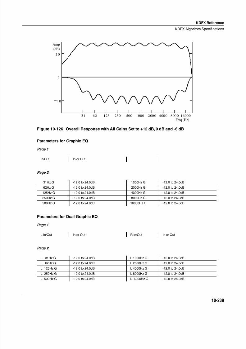
8/21/2019 MR_K2661
http://slidepdf.com/reader/full/mrk2661 321/499
KDFX Reference
KDFX Algorithm Specifications
10-239
Figure 10-126 Overall Response with All Gains Set to +12 dB, 0 dB and -6 dB
Parameters for Graphic EQ
Page 1
Page 2
Parameters for Dual Graphic EQ
Page 1
Page 2
In/Out In or Out
31Hz G -12.0 to 24.0dB 1000Hz G -12.0 to 24.0dB 62Hz G -12.0 to 24.0dB 2000Hz G -12.0 to 24.0dB
125Hz G -12.0 to 24.0dB 4000Hz G -12.0 to 24.0dB
250Hz G -12.0 to 24.0dB 8000Hz G -12.0 to 24.0dB
500Hz G -12.0 to 24.0dB 16000Hz G -12.0 to 24.0dB
L In/Out In or Out R In/Out In or Out
L 31Hz G -12.0 to 24.0dB L 1000Hz G -12.0 to 24.0dB
L 62Hz G -12.0 to 24.0dB L 2000Hz G -12.0 to 24.0dB
L 125Hz G -12.0 to 24.0dB L 4000Hz G -12.0 to 24.0dB
L 250Hz G -12.0 to 24.0dB L 8000Hz G -12.0 to 24.0dB
L 500Hz G -12.0 to 24.0dB L16000Hz G -12.0 to 24.0dB
10
0
10
31 6 2 125 250 500 1000 160002 00 0 4 00 0 8 00 0Freq (Hz)
Amp
(dB)
8/21/2019 MR_K2661
http://slidepdf.com/reader/full/mrk2661 322/499
10-240
KDFX Reference
KDFX Algorithm Specifications
Page 3
In/Out When set to In the left channel equalizer is active; when set to Out the left channelequalizer is bypassed.
31Hz G Gain of the left 31 Hz band in dB.
62Hz G Gain of the left 62 Hz band in dB.
125Hz G Gain of the left 125 Hz band in dB.
250Hz G Gain of the left 250 Hz band in dB.500Hz G Gain of the left 500 Hz band in dB.
1000Hz G Gain of the left 1000 Hz band in dB.
2000Hz G Gain of the left 2000 Hz band in dB.
4000Hz G Gain of the left 4000 Hz band in dB.
8000Hz G Gain of the left 8000 Hz band in dB.
16000Hz G Gain of the left 16000 Hz band in dB.
R 31Hz G -12.0 to 24.0dB R 1000Hz G -12.0 to 24.0dB
R 62Hz G -12.0 to 24.0dB R 2000Hz G -12.0 to 24.0dB
R 125Hz G -12.0 to 24.0dB R 4000Hz G -12.0 to 24.0dBR 250Hz G -12.0 to 24.0dB R 8000Hz G -12.0 to 24.0dB
R 500Hz G -12.0 to 24.0dB R16000Hz G -12.0 to 24.0dB
8/21/2019 MR_K2661
http://slidepdf.com/reader/full/mrk2661 323/499
KDFX Reference
KDFX Algorithm Specifications
10-241
970 5 Band EQ
Stereo bass and treble shelving filters and 3 parametric EQs
PAUs: 3
This algorithm is a stereo 5 band equalizer with 3 bands of parametric EQ and with bass and treble tonecontrols. The user has control over the gain, frequency and bandwidth of each band of parametric EQ andcontrol of the gain and frequencies of the bass and treble tone controls. The controls for the two stereochannels are ganged.
Parameters
Page 1
Page 2
Page 3
In/Out When set to “In” the tone controls are active; when set to “Out” the tone controls are bypassed.
Bass Gain The amount of boost or cut that the filter should apply to the low frequency signals in dB.Every increase of 6 dB approximately doubles the amplitude of the signal. Positive values boost the bass signal below the specified frequency. Negative values cut the bass signal below the specified frequency.
Bass Freq The center frequency of the bass shelving filters in intervals of one semitone.
Treb Gain The amount of boost or cut that thefi
lter should apply to the high frequency signals in dB.Every increase of 6 dB approximately doubles the amplitude of the signal. Positive values boost the treble signal above the specified frequency. Negative values cut the treble signalabove the specified frequency.
Treb Freq The center frequency of the treble shelving filters in intervals of one semitone.
Midn Gain The amount of boost or cut that the filter should apply in dB. Every increase of 6 dBapproximately doubles the amplitude of the signal. Positive values boost the signal at thespecified frequency. Negative values cut the signal at the specified frequency.
In/Out In or Out
Bass Gain -79.0 to 24.0 dB Treb Gain -79.0 to 24.0 dB
Bass Freq 16 to 25088 Hz Treb Freq 16 to 25088 Hz
Mid1 Gain -79.0 to 24.0 dB Mid2 Gain -79.0 to 24.0 dB
Mid1 Freq 16 to 25088 Hz Mid2 Freq 16 to 25088 Hz
Mid1 Width 0.010 to 5.000 oct Mid2 Width 0.010 to 5.000 oct
Mid3 Gain -79.0 to 24.0 dB
Mid3 Freq 16 to 25088 HzMid3 Width 0.010 to 5.000 oct
8/21/2019 MR_K2661
http://slidepdf.com/reader/full/mrk2661 324/499
10-242
KDFX Reference
KDFX Algorithm Specifications
Midn Freq The center frequency of the EQ in intervals of one semitone. The boost or cut will be at amaximum at this frequency.
Midn Width The bandwidth of the EQ may be adjusted. You specify the bandwidth in octaves. Smallvalues result in a very narrow filter response. Large values result in a very broad response.
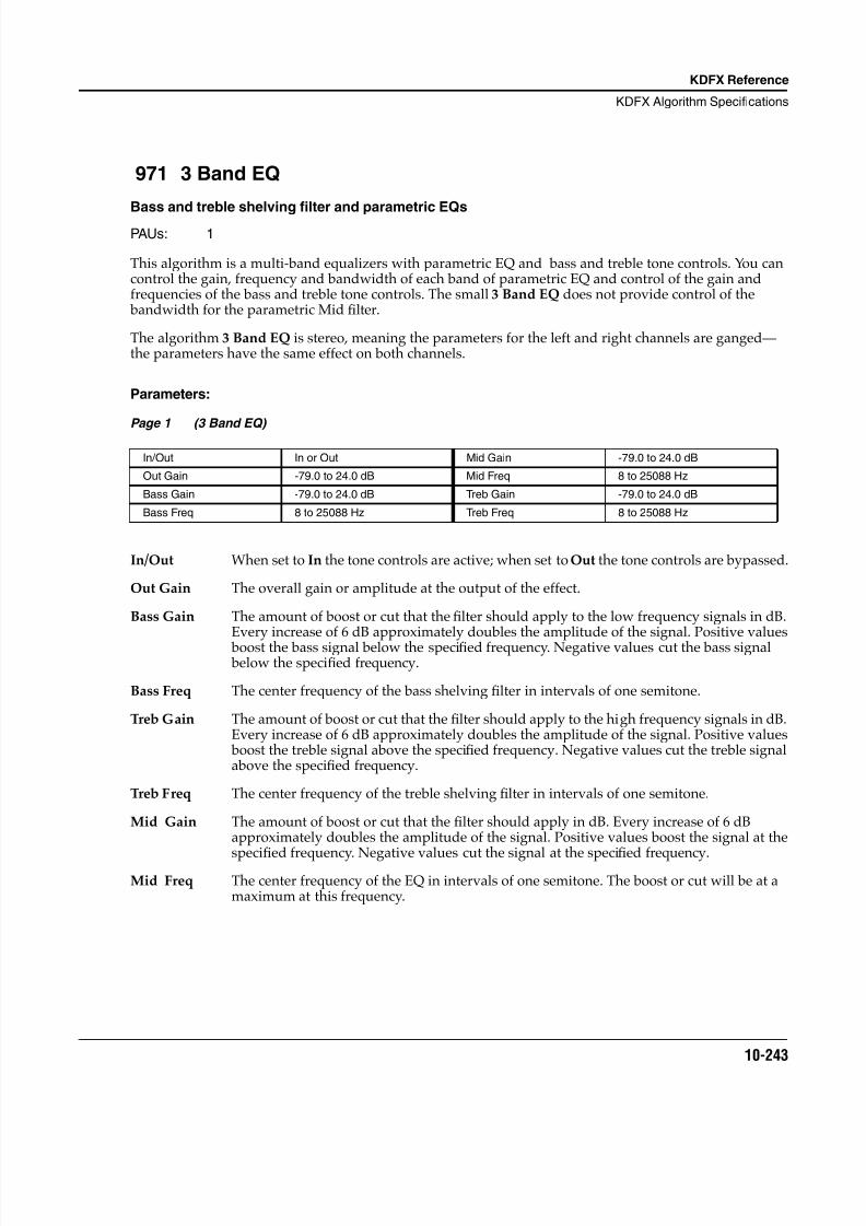
8/21/2019 MR_K2661
http://slidepdf.com/reader/full/mrk2661 325/499
KDFX Reference
KDFX Algorithm Specifications
10-243
971 3 Band EQ
Bass and treble shelving filter and parametric EQs
PAUs: 1
This algorithm is a multi-band equalizers with parametric EQ and bass and treble tone controls. You cancontrol the gain, frequency and bandwidth of each band of parametric EQ and control of the gain andfrequencies of the bass and treble tone controls. The small 3 Band EQ does not provide control of the bandwidth for the parametric Mid filter.
The algorithm 3 Band EQ is stereo, meaning the parameters for the left and right channels are ganged—the parameters have the same effect on both channels.
Parameters:
Page 1 (3 Band EQ)
In/Out When set to In the tone controls are active; when set to Out the tone controls are bypassed.
Out Gain The overall gain or amplitude at the output of the effect.
Bass Gain The amount of boost or cut that the filter should apply to the low frequency signals in dB.Every increase of 6 dB approximately doubles the amplitude of the signal. Positive values
boost the bass signal below the specified frequency. Negative values cut the bass signal below the specified frequency.
Bass Freq The center frequency of the bass shelving filter in intervals of one semitone.
Treb Gain The amount of boost or cut that the filter should apply to the high frequency signals in dB.Every increase of 6 dB approximately doubles the amplitude of the signal. Positive values boost the treble signal above the specified frequency. Negative values cut the treble signalabove the specified frequency.
Treb Freq The center frequency of the treble shelving filter in intervals of one semitone.
Mid Gain The amount of boost or cut that the filter should apply in dB. Every increase of 6 dBapproximately doubles the amplitude of the signal. Positive values boost the signal at the
specifi
ed frequency. Negative values cut the signal at the specifi
ed frequency.Mid Freq The center frequency of the EQ in intervals of one semitone. The boost or cut will be at a
maximum at this frequency.
In/Out In or Out Mid Gain -79.0 to 24.0 dB
Out Gain -79.0 to 24.0 dB Mid Freq 8 to 25088 Hz
Bass Gain -79.0 to 24.0 dB Treb Gain -79.0 to 24.0 dB
Bass Freq 8 to 25088 Hz Treb Freq 8 to 25088 Hz
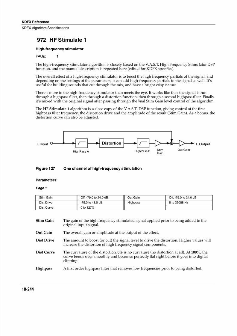
8/21/2019 MR_K2661
http://slidepdf.com/reader/full/mrk2661 326/499
10-244
KDFX Reference
KDFX Algorithm Specifications
972 HF Stimulate 1
High-frequency stimulator
PAUs: 1
The high-frequency stimulator algorithm is closely based on the V.A.S.T. High Frequency Stimulator DSPfunction, and the manual description is repeated here (edited for KDFX specifics).
The overall effect of a high-frequency stimulator is to boost the high frequency partials of the signal, anddepending on the settings of the parameters, it can add high-frequency partials to the signal as well. It’suseful for building sounds that cut through the mix, and have a bright crisp nature.
There’s more to the high-frequency stimulator than meets the eye. It works like this: the signal is runthrough a highpass filter, then through a distortion function, then through a second highpass filter. Finally.it’s mixed with the original signal after passing through the final Stim Gain level control of the algorithm.
The HF Stimulate 1 algorithm is a close copy of the V.A.S.T. DSP function, giving control of the firsthighpass filter frequency, the distortion drive and the amplitude of the result (Stim Gain). As a bonus, the
distortion curve can also be adjusted.
Figure 127 One channel of high-frequency stimulation
Parameters:
Page 1
Stim Gain The gain of the high frequency stimulated signal applied prior to being added to theoriginal input signal.
Out Gain The overall gain or amplitude at the output of the effect.
Dist Drive The amount to boost (or cut) the signal level to drive the distortion. Higher values willincrease the distortion of high frequency signal components.
Dist Curve The curvature of the distortion. 0% is no curvature (no distortion at all). At 100% , thecurve bends over smoothly and becomes perfectly flat right before it goes into digitalclipping.
Highpass A first order highpass filter that removes low frequencies prior to being distorted.
Stim Gain Off, -79.0 to 24.0 dB Out Gain Off, -79.0 to 24.0 dB
Dist Drive -79.0 to 48.0 dB Highpass 8 to 25088 Hz
Dist Curve 0 to 127%
L Input L Outputistortion
HighPass A HighPass B StimGain
Out Gain
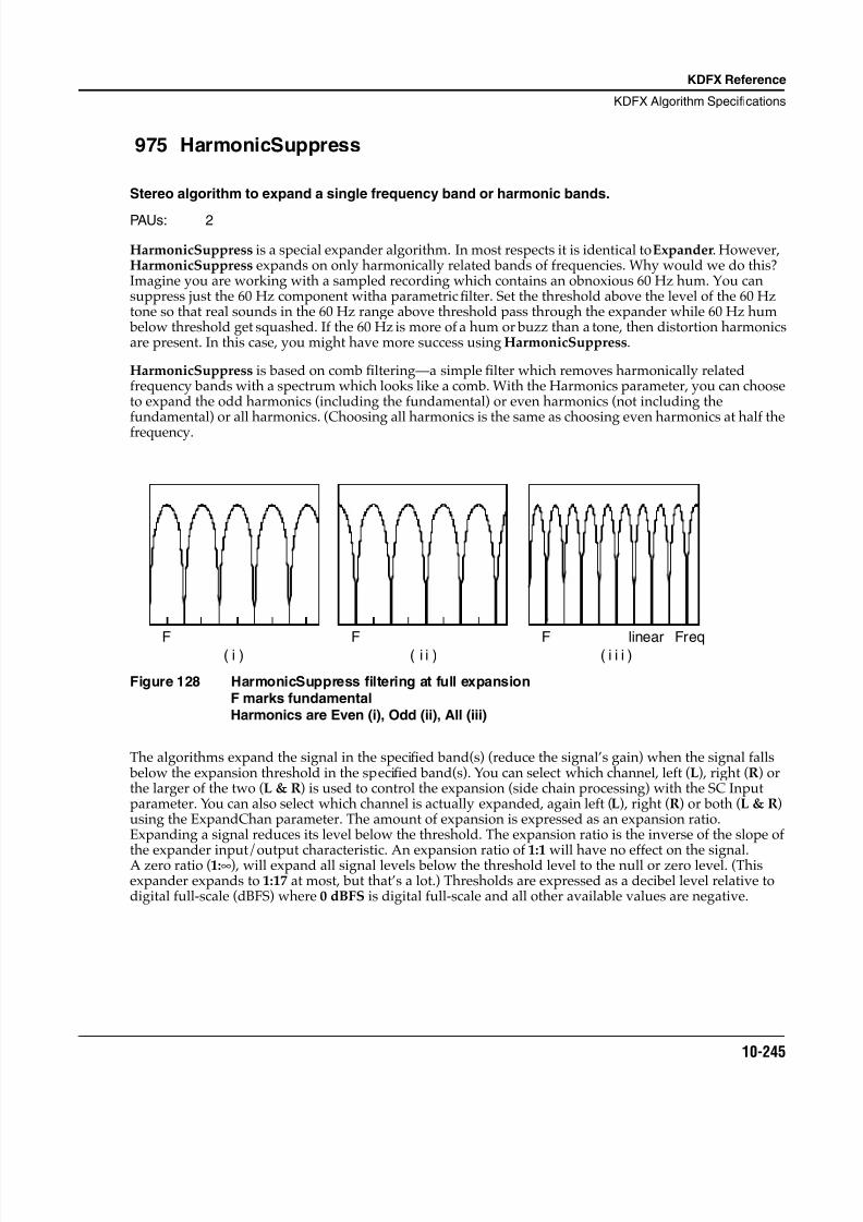
8/21/2019 MR_K2661
http://slidepdf.com/reader/full/mrk2661 327/499
KDFX Reference
KDFX Algorithm Specifications
10-245
975 HarmonicSuppress
Stereo algorithm to expand a single frequency band or harmonic bands.
PAUs: 2
HarmonicSuppress is a special expander algorithm. In most respects it is identical to Expander. However,HarmonicSuppress expands on only harmonically related bands of frequencies. Why would we do this?Imagine you are working with a sampled recording which contains an obnoxious 60 Hz hum. You cansuppress just the 60 Hz component witha parametric filter. Set the threshold above the level of the 60 Hztone so that real sounds in the 60 Hz range above threshold pass through the expander while 60 Hz hum below threshold get squashed. If the 60 Hz is more of a hum or buzz than a tone, then distortion harmonicsare present. In this case, you might have more success using HarmonicSuppress.
HarmonicSuppress is based on comb filtering—a simple filter which removes harmonically relatedfrequency bands with a spectrum which looks like a comb. With the Harmonics parameter, you can chooseto expand the odd harmonics (including the fundamental) or even harmonics (not including thefundamental) or all harmonics. (Choosing all harmonics is the same as choosing even harmonics at half thefrequency.
Figure 128 HarmonicSuppress filtering at full expansionF marks fundamentalHarmonics are Even (i), Odd (ii), All (iii)
The algorithms expand the signal in the specified band(s) (reduce the signal’s gain) when the signal falls below the expansion threshold in the specified band(s). You can select which channel, left (L), right (R) orthe larger of the two (L & R) is used to control the expansion (side chain processing) with the SC Inputparameter. You can also select which channel is actually expanded, again left (L), right (R) or both (L & R)using the ExpandChan parameter. The amount of expansion is expressed as an expansion ratio.Expanding a signal reduces its level below the threshold. The expansion ratio is the inverse of the slope of
the expander input/output characteristic. An expansion ratio of 1:1 will have no effect on the signal.A zero ratio (1:∞), will expand all signal levels below the threshold level to the null or zero level. (Thisexpander expands to 1:17 at most, but that’s a lot.) Thresholds are expressed as a decibel level relative todigital full-scale (dBFS) where 0 dBFS is digital full-scale and all other available values are negative.
F F linear Freq( i i i )F ( i ) ( i i )
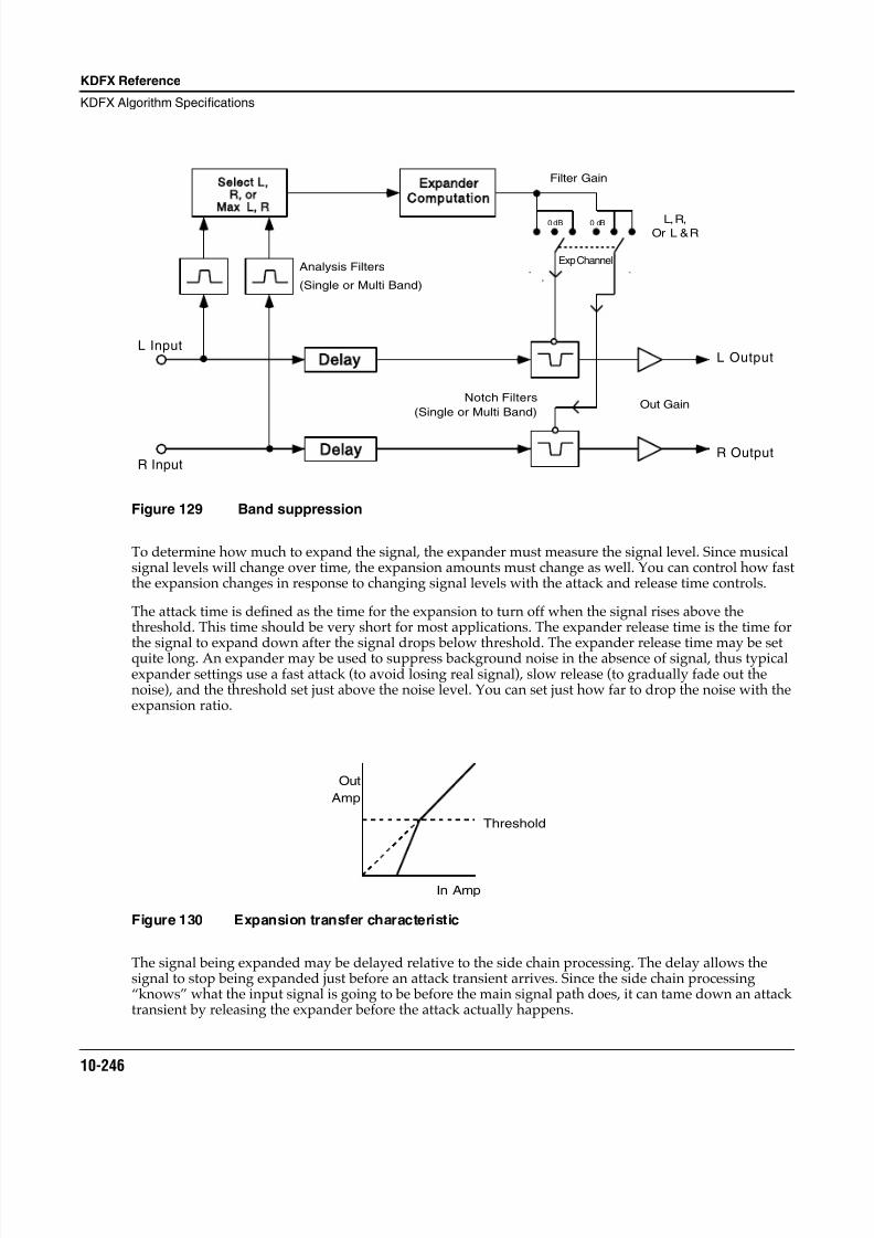
8/21/2019 MR_K2661
http://slidepdf.com/reader/full/mrk2661 328/499
10-246
KDFX Reference
KDFX Algorithm Specifications
Figure 129 Band suppression
To determine how much to expand the signal, the expander must measure the signal level. Since musicalsignal levels will change over time, the expansion amounts must change as well. You can control how fastthe expansion changes in response to changing signal levels with the attack and release time controls.
The attack time is defined as the time for the expansion to turn off when the signal rises above thethreshold. This time should be very short for most applications. The expander release time is the time for
the signal to expand down after the signal drops below threshold. The expander release time may be setquite long. An expander may be used to suppress background noise in the absence of signal, thus typicalexpander settings use a fast attack (to avoid losing real signal), slow release (to gradually fade out thenoise), and the threshold set just above the noise level. You can set just how far to drop the noise with theexpansion ratio.
Figure 130 Expansion transfer characteristic
The signal being expanded may be delayed relative to the side chain processing. The delay allows thesignal to stop being expanded just before an attack transient arrives. Since the side chain processing“knows” what the input signal is going to be before the main signal path does, it can tame down an attacktransient by releasing the expander before the attack actually happens.
L Input
R Input
L Output
R Output
Filter GainSelect L
R orMax L R
ExpanderComputation
Delay
Delay
Analysis Filters
(Single or Multi Band)
L, R,Or L & R
Out GainNotch Filters
(Single or Multi Band)
0 dB
Exp Channel
0 dB
Out
Amp
In Amp
Threshold
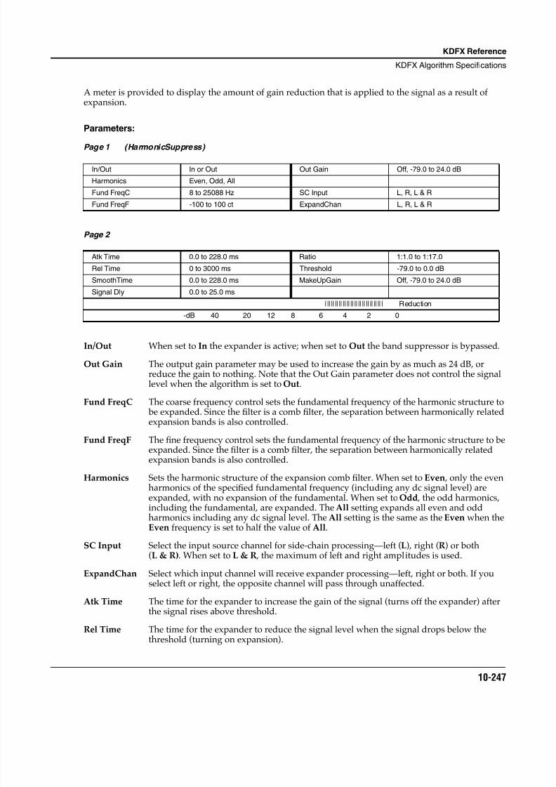
8/21/2019 MR_K2661
http://slidepdf.com/reader/full/mrk2661 329/499
KDFX Reference
KDFX Algorithm Specifications
10-247
A meter is provided to display the amount of gain reduction that is applied to the signal as a result ofexpansion.
Parameters:
Page 1 (HarmonicSuppress)
Page 2
In/Out When set to In the expander is active; when set to Out the band suppressor is bypassed.
Out Gain The output gain parameter may be used to increase the gain by as much as 24 dB, orreduce the gain to nothing. Note that the Out Gain parameter does not control the signallevel when the algorithm is set to Out.
Fund FreqC The coarse frequency control sets the fundamental frequency of the harmonic structure to
be expanded. Since the filter is a comb filter, the separation between harmonically relatedexpansion bands is also controlled.
Fund FreqF The fine frequency control sets the fundamental frequency of the harmonic structure to beexpanded. Since the filter is a comb filter, the separation between harmonically relatedexpansion bands is also controlled.
Harmonics Sets the harmonic structure of the expansion comb filter. When set to Even , only the evenharmonics of the specified fundamental frequency (including any dc signal level) areexpanded, with no expansion of the fundamental. When set to Odd , the odd harmonics,including the fundamental, are expanded. The All setting expands all even and oddharmonics including any dc signal level. The All setting is the same as the Even when theEven frequency is set to half the value of All.
SC Input Select the input source channel for side-chain processing—left (L), right (R) or both(L & R). When set to L & R , the maximum of left and right amplitudes is used.
ExpandChan Select which input channel will receive expander processing—left, right or both. If youselect left or right, the opposite channel will pass through unaffected.
Atk Time The time for the expander to increase the gain of the signal (turns off the expander) afterthe signal rises above threshold.
Rel Time The time for the expander to reduce the signal level when the signal drops below thethreshold (turning on expansion).
In/Out In or Out Out Gain Off, -79.0 to 24.0 dB
Harmonics Even, Odd, All
Fund FreqC 8 to 25088 Hz SC Input L, R, L & R
Fund FreqF -100 to 100 ct ExpandChan L, R, L & R
Atk Time 0.0 to 228.0 ms Ratio 1:1.0 to 1:17.0
Rel Time 0 to 3000 ms Threshold -79.0 to 0.0 dB
SmoothTime 0.0 to 228.0 ms MakeUpGain Off, -79.0 to 24.0 dB
Signal Dly 0.0 to 25.0 ms
|||||||||||||||||||||||||||||| Reduction
-dB 40 20 12 8 6 4 2 0
8/21/2019 MR_K2661
http://slidepdf.com/reader/full/mrk2661 330/499
10-248
KDFX Reference
KDFX Algorithm Specifications
SmoothTime A lowpass filter in the control signal path. It is intended to smooth the output of theexpander’s envelope detector. Smoothing will affect the attack or release times when thesmoothing time is longer than one of the other times.
Signal Dly The time in ms by which the input signal should be delayed with respect to expander sidechain processing (i.e. side chain predelay). This allows the expansion to appear to turn off just before the signal actually rises.
Ratio The expansion ratio. High values (1:17 max) are highly expanded, low values (1:1 min) aremoderately expanded.
Threshold The expansion threshold level in dBFS (decibels relative to full scale) below which thesignal begins to be expanded.
MakeUpGain Provides an additional control of the output gain. The Out Gain and MakeUpGaincontrols are additive (in decibels) and together may provide a maximum of 24 dB boost tooffset gain reduction due to expansion.
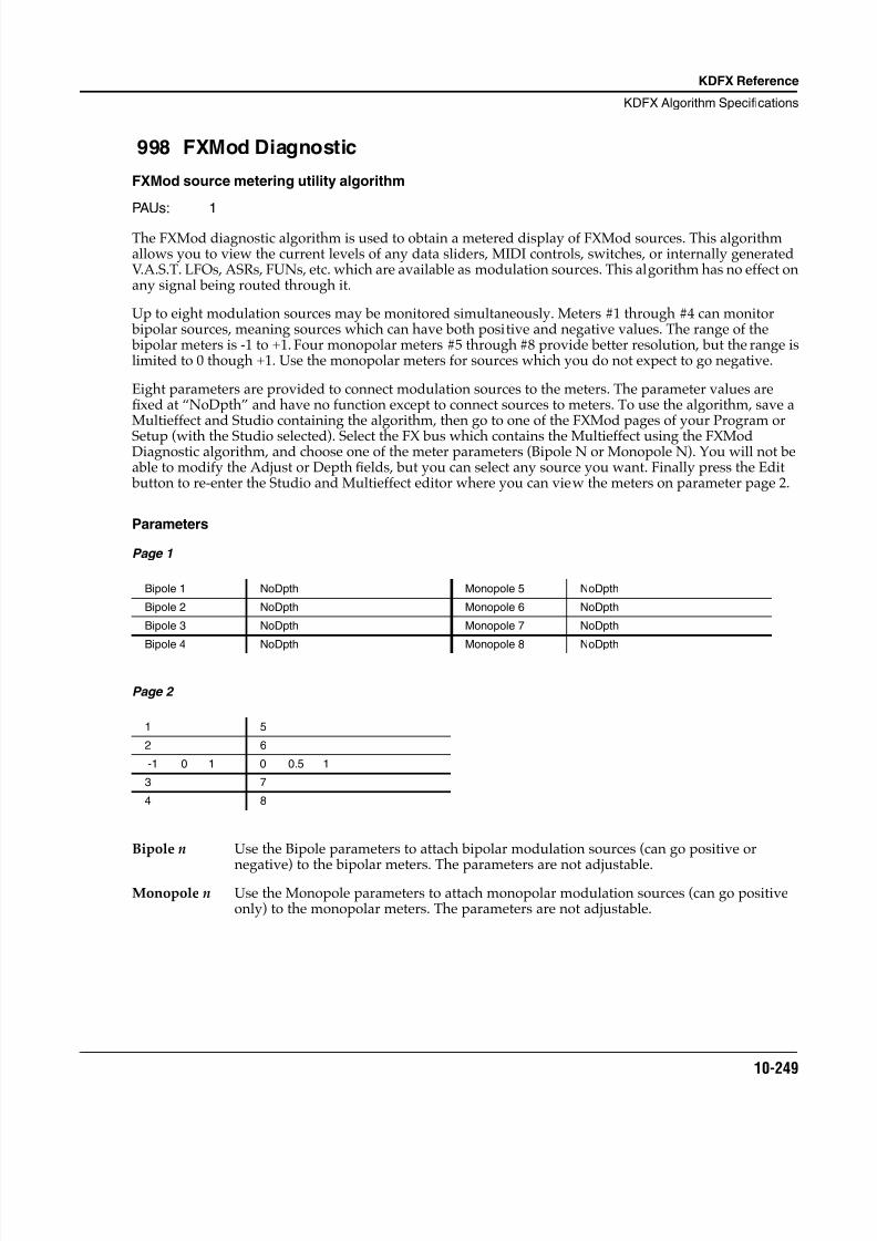
8/21/2019 MR_K2661
http://slidepdf.com/reader/full/mrk2661 331/499
KDFX Reference
KDFX Algorithm Specifications
10-249
998 FXMod Diagnostic
FXMod source metering utility algorithm
PAUs: 1
The FXMod diagnostic algorithm is used to obtain a metered display of FXMod sources. This algorithmallows you to view the current levels of any data sliders, MIDI controls, switches, or internally generatedV.A.S.T. LFOs, ASRs, FUNs, etc. which are available as modulation sources. This algorithm has no effect onany signal being routed through it.
Up to eight modulation sources may be monitored simultaneously. Meters #1 through #4 can monitor bipolar sources, meaning sources which can have both positive and negative values. The range of the bipolar meters is -1 to +1. Four monopolar meters #5 through #8 provide better resolution, but the range islimited to 0 though +1. Use the monopolar meters for sources which you do not expect to go negative.
Eight parameters are provided to connect modulation sources to the meters. The parameter values arefixed at “NoDpth” and have no function except to connect sources to meters. To use the algorithm, save aMultieffect and Studio containing the algorithm, then go to one of the FXMod pages of your Program or
Setup (with the Studio selected). Select the FX bus which contains the Multieffect using the FXModDiagnostic algorithm, and choose one of the meter parameters (Bipole N or Monopole N). You will not beable to modify the Adjust or Depth fields, but you can select any source you want. Finally press the Edit button to re-enter the Studio and Multieffect editor where you can view the meters on parameter page 2.
Parameters
Page 1
Page 2
Bipole n Use the Bipole parameters to attach bipolar modulation sources (can go positive or
negative) to the bipolar meters. The parameters are not adjustable.Monopole n Use the Monopole parameters to attach monopolar modulation sources (can go positive
only) to the monopolar meters. The parameters are not adjustable.
Bipole 1 NoDpth Monopole 5 NoDpth
Bipole 2 NoDpth Monopole 6 NoDpth
Bipole 3 NoDpth Monopole 7 NoDpth
Bipole 4 NoDpth Monopole 8 NoDpth
1 5
2 6
-1 0 1 0 0.5 1
3 7
4 8
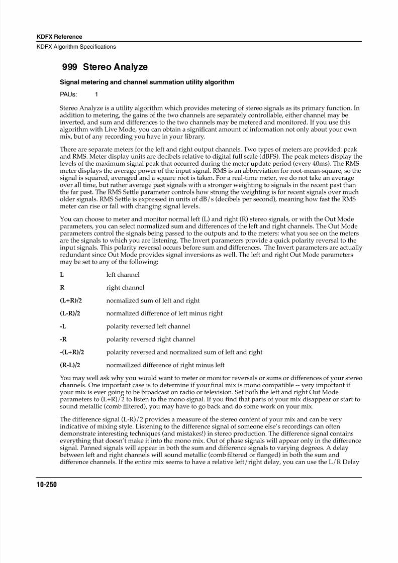
8/21/2019 MR_K2661
http://slidepdf.com/reader/full/mrk2661 332/499
10-250
KDFX Reference
KDFX Algorithm Specifications
999 Stereo Analyze
Signal metering and channel summation utility algorithm
PAUs: 1
Stereo Analyze is a utility algorithm which provides metering of stereo signals as its primary function. Inaddition to metering, the gains of the two channels are separately controllable, either channel may beinverted, and sum and differences to the two channels may be metered and monitored. If you use thisalgorithm with Live Mode, you can obtain a significant amount of information not only about your ownmix, but of any recording you have in your library.
There are separate meters for the left and right output channels. Two types of meters are provided: peakand RMS. Meter display units are decibels relative to digital full scale (dBFS). The peak meters display thelevels of the maximum signal peak that occurred during the meter update period (every 40ms). The RMSmeter displays the average power of the input signal. RMS is an abbreviation for root-mean-square, so thesignal is squared, averaged and a square root is taken. For a real-time meter, we do not take an averageover all time, but rather average past signals with a stronger weighting to signals in the recent past thanthe far past. The RMS Settle parameter controls how strong the weighting is for recent signals over mucholder signals. RMS Settle is expressed in units of dB/s (decibels per second), meaning how fast the RMSmeter can rise or fall with changing signal levels.
You can choose to meter and monitor normal left (L) and right (R) stereo signals, or with the Out Modeparameters, you can select normalized sum and differences of the left and right channels. The Out Modeparameters control the signals being passed to the outputs and to the meters: what you see on the metersare the signals to which you are listening. The Invert parameters provide a quick polarity reversal to theinput signals. This polarity reversal occurs before sum and differences. The Invert parameters are actuallyredundant since Out Mode provides signal inversions as well. The left and right Out Mode parametersmay be set to any of the following:
L left channel
R right channel
(L+R)/2 normalized sum of left and right
(L-R)/2 normalized difference of left minus right
-L polarity reversed left channel
-R polarity reversed right channel
-(L+R)/2 polarity reversed and normalized sum of left and right
(R-L)/2 normailized difference of right minus left
You may well ask why you would want to meter or monitor reversals or sums or differences of your stereochannels. One important case is to determine if your final mix is mono compatible -- very important if
your mix is ever going to be broadcast on radio or television. Set both the left and right Out Modeparameters to (L+R)/2 to listen to the mono signal. If you find that parts of your mix disappear or start tosound metallic (comb filtered), you may have to go back and do some work on your mix.
The difference signal (L-R)/2 provides a measure of the stereo content of your mix and can be veryindicative of mixing style. Listening to the difference signal of someone else’s recordings can oftendemonstrate interesting techniques (and mistakes!) in stereo production. The difference signal containseverything that doesn’t make it into the mono mix. Out of phase signals will appear only in the differencesignal. Panned signals will appear in both the sum and difference signals to varying degrees. A delay between left and right channels will sound metallic (comb filtered or flanged) in both the sum anddifference channels. If the entire mix seems to have a relative left/right delay, you can use the L/R Delay
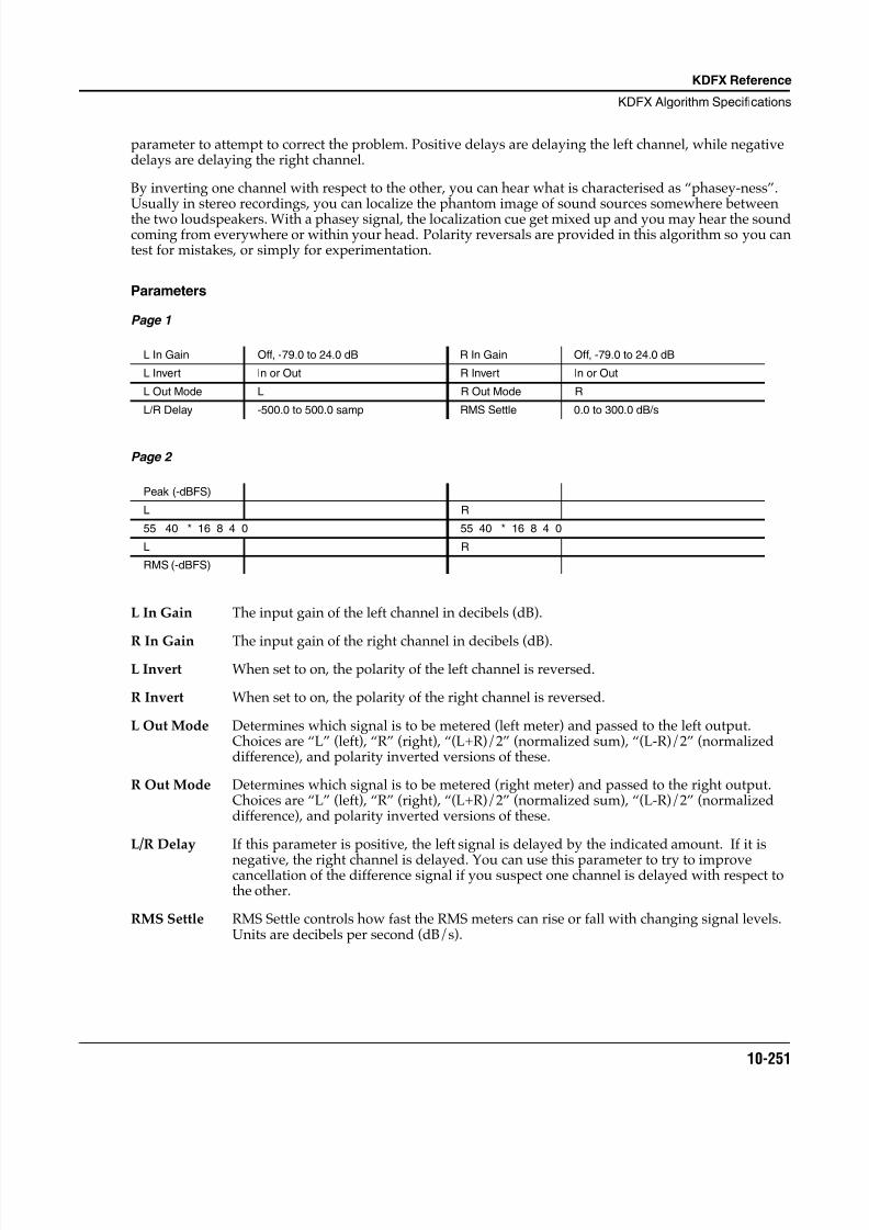
8/21/2019 MR_K2661
http://slidepdf.com/reader/full/mrk2661 333/499
KDFX Reference
KDFX Algorithm Specifications
10-251
parameter to attempt to correct the problem. Positive delays are delaying the left channel, while negativedelays are delaying the right channel.
By inverting one channel with respect to the other, you can hear what is characterised as “phasey-ness”.Usually in stereo recordings, you can localize the phantom image of sound sources somewhere betweenthe two loudspeakers. With a phasey signal, the localization cue get mixed up and you may hear the soundcoming from everywhere or within your head. Polarity reversals are provided in this algorithm so you cantest for mistakes, or simply for experimentation.
Parameters
Page 1
Page 2
L In Gain The input gain of the left channel in decibels (dB).
R In Gain The input gain of the right channel in decibels (dB).L Invert When set to on, the polarity of the left channel is reversed.
R Invert When set to on, the polarity of the right channel is reversed.
L Out Mode Determines which signal is to be metered (left meter) and passed to the left output.Choices are “L” (left), “R” (right), “(L+R)/2” (normalized sum), “(L-R)/2” (normalizeddifference), and polarity inverted versions of these.
R Out Mode Determines which signal is to be metered (right meter) and passed to the right output.Choices are “L” (left), “R” (right), “(L+R)/2” (normalized sum), “(L-R)/2” (normalizeddifference), and polarity inverted versions of these.
L/R Delay If this parameter is positive, the left signal is delayed by the indicated amount. If it is
negative, the right channel is delayed. You can use this parameter to try to improvecancellation of the difference signal if you suspect one channel is delayed with respect tothe other.
RMS Settle RMS Settle controls how fast the RMS meters can rise or fall with changing signal levels.Units are decibels per second (dB/s).
L In Gain Off, -79.0 to 24.0 dB R In Gain Off, -79.0 to 24.0 dB
L Invert In or Out R Invert In or Out
L Out Mode L R Out Mode R
L/R Delay -500.0 to 500.0 samp RMS Settle 0.0 to 300.0 dB/s
Peak (-dBFS)
L R
55 40 * 16 8 4 0 55 40 * 16 8 4 0
L R
RMS (-dBFS)
8/21/2019 MR_K2661
http://slidepdf.com/reader/full/mrk2661 334/499
10-252
KDFX Reference
KDFX Algorithm Specifications
8/21/2019 MR_K2661
http://slidepdf.com/reader/full/mrk2661 335/499
Glossary
11-1
Chapter 11
Glossary
Algorithm In the K2661, a preset configuration of programmable digital signal processingfunctions. Each of a program’s layers uses its own algorithm, which determines thetype of synthesis each layer uses to generate its sound. FX presets also use algorithms,which determine what kind of DSP gets applied to the signal as it passes through astudio.
Aliasing A type of distortion that occurs in digitally sampled sounds when higher pitches(increased sample playback rates) introduce partials that were not present in theoriginal sound. These partials may or may not be musically useful.
Amplitude The intensity of a signal, perceived as loudness in the case of audio signals.
Analog A term used widely in electronics-related fields to describe a method of representinginformation, in which the method of representation resembles the information itself.Analog synthesizers, for example, use gradual variations in electrical voltage to createand modify sounds. The oscillations in voltage are analogous to the waveforms of thesounds they generate. Compare Digital.
Bandwidth In terms of sound generation, the range of frequencies within which a devicefunctions. The human ear has a “bandwidth” of almost 20 KHz (it can distinguishsound at frequencies from 20 Hz to 20KHz). The K2661’s 20KHz bandwidth enables itto produce sounds that span the entire range of humanly audible sound.
Bank There are two types of banks in the K2661’s memory: memory banks, which store andorganize the programs and other objects you create, and Quick Access banks, where
you can store programs and setups for one-button access while in Quick Access mode.
Cent 1/100th of a semitone. The standard increment for fine adjustment of pitch.
Continuous control A device that converts motion into a range of 128 possible values that can modulate asound source. The Mod Wheel, a standard volume pedal, and controllers like Breathand Aftertouch are continuous controls. Compare Switch controls.
Control Source Anything that can be used to modify some aspect of a program’s sound. LFOs,envelopes, Mod Wheel messages (MIDI 01), and FUNs are just a few examples of theK2661’s control sources.
DSP Digital signal processing (see).
DSP Functions The K2661’s collection of digital signal processing functions are what give the Variable
Architecture Synthesis system its flexibility. Within each layer’s algorithm, you canselect from a long list of DSP functions like filters, EQ, oscillators, and a few that areunique to the K2661. Each DSP function has a corresponding page that enables you toassign numerous control sources to define how the DSP functions affect the sound ofthe program you’re editing.
Default The starting condition of a system. The settings for the K2661’s parameters are at theirdefaults when you unpack it, and they stay there until you change them. A hard resetwill erase RAM and restore all parameters to their defaults.
8/21/2019 MR_K2661
http://slidepdf.com/reader/full/mrk2661 336/499
11-2
Glossary
Dialog A page that prompts you to enter information that the K2661 needs in order to executean operation. Dialogs appear, for example, when you initiate a Save or Deleteoperation.
Digital A term used widely in electronics-related fields to describe a method of representinginformation as a series of binary digits (bits)—1s and 0s. Digital computers processthese strings of 1s and 0s by converting them into an electrical signal that is always inone of two very definite states: “on” or “off.” This is much more precise than theanalog method, therefore digital computers can operate at speeds unattainable byanalog devices. Digital synthesizers like the K2661 are actually computers that processvast strings of digital information signals, eventually converting them (at the audiooutput) into the analog signals that flow into PAs and other audio systems. See alsoAnalog.
Digital Signal Processing The term “Signal processing” refers to a vast range of functions, all of which have incommon the fact that they act upon an electric current as it flows through a circuit orgroup of circuits. A simple form of signal processing is the distortion box used bymany guitarists. Digital signal processing refers to similar processes that areperformed by digital (see) circuitry as opposed to analog (see) circuitry. Many of the
effects devices available today use digital signal processing techniques.
Drum Program Any program consisting of more than three layers. So called because in the K2000, aspecial channel was required to handle programs with more than three layers—whichtypically were-multi-timbral percussion programs.
Editor The complete set of parameters used to modify a particular aspect of the K2661, forexample, the currently selected Program, which is modified with the Program Editor.The Program Editor spans several display pages, which can be viewed by using thesoft buttons (the ones labeled <more>).
Envelope An aperiodic modifier. In other words, a way to cause a sound to change over timewithout repeating the change (unlike periodic modifiers like LFOs, which repeat atregular intervals).
File A group of objects stored to a floppy or hard disk, or loaded into the K2661’s RAMfrom disk.
Global In this manual, used primarily in reference to control sources. A global control sourceaffects all notes in a layer uniformly. If a layer uses a global control source, that controlsource begins to run as soon as the program containing it is selected. Its effect on eachnote will be completely in phase, regardless how many notes are being played.Compare Local.
Hard Reset Resets all parameter values to their defaults, and completely erases the contents ofRAM. Press the Reset button in Master mode (Mast2 page) to do a hard reset. This is aquick way to restore the factory defaults to your K2661, but everything in RAM (all theobjects you’ve created) will be erased, so objects you wish to keep should be saved todisk or SyxEx dump. A hard reset should not be used to recover if your K2661 is hungup, except as a last resort. See Soft Reset.
KB3 Program Uses oscillators to emulate tone wheel organs. Doesn’t use VAST processing; nolayers, keymaps, or algorithms. Requires a special channel called the KB3 channel.
Keymap A keymap is a collection of samples assigned to specific notes and attack velocities.Keymaps usually contain numerous sample roots pitch-shifted across a range ofseveral notes. When you trigger a note, the keymap tells the K2661 what sound toplay, at what pitch, and at what loudness.
8/21/2019 MR_K2661
http://slidepdf.com/reader/full/mrk2661 337/499
Glossary
11-3
LFO Low frequency oscillator. An oscillator is an electrical signal that cycles regularly between a minimum and maximum amplitude. The simplest oscillating waveform isthe sine wave, but an LFO waveform can have almost any shape. The number of timeseach second that an oscillator repeats itself is called its frequency, which is measuredin Hertz (Hz). Anything up to 50 Hz is considered low-frequency in musicalapplications. Use an LFO whenever you want to generate a periodic (repeating) effect.Adjusting the rate of the LFO will change the repetition rate of the effect.
Layer A layer consists of a keymap processed through an algorithm. Layers can be stackedtogether within a program. Each layer uses one of the K2661’s 48 available voices.Each K2661 program can contain up to 32 layers. Any program can contain up to 32layers. Ones with more than three show up in display as "Drum" programs.
Leslie effect This classic vibrato effect was originally created by mounting a speaker in its cabinetso the speaker could be rotated at varying speeds. This applied a vibrato of varyingrate to all sounds played through the rotating speaker.
Local In this manual, used primarily in reference to control sources. A local control sourceaffects each note in a layer independently. For example, if a local LFO is used as a
control source, a separate LFO cycle will begin with each note start. The LFOs don’trun in phase unless notes are started simultaneously. Compare Global.
Memory banks The K2661’s memory is divided into ten spaces where you can store any object youedit. These spaces are called banks. Each bank can hold up to 100 objects of each type,so we refer to them as the 100s bank, the 200s bank, and so on. The ID of an objectdetermines which bank it’s stored in. An object with an ID of 399, for example, would be stored in the 300s bank. ROM objects are stored in the Zeros and 100s banks. RAMobjects can be stored in any bank.
MIDI Musical Instrument Digital Interface. A specialized format for representing musicalinformation in terms of standardized computer data, which enables electronic musicalinstruments to communicate with computers
MIDI device Any device—keyboard, computer, wind instrument, etc.—that is capable oftransmitting and receiving MIDI messages. Also known as a MIDI controller, or aMIDI source.
MIDI Master A MIDI device that is configured to control one or more other MIDI devices. TheMIDI Out port of the master is connected by cable to the MIDI In port(s) of the slavedevice(s).
MIDI Slave A MIDI device that is configured to receive MIDI messages from a master device. TheMIDI In port of the slave is connected by cable to the MIDI Out port of the master.
Nonlinear DSP Function Without getting technical, nonlinear DSP functions like SHAPER and WRAP addwaveforms to those already present in a sound, while linear DSP functions act uponthe existing waveforms without adding new ones.
Note State Any K2661 note is either on or off; this is its note state. Normally, any given note’sNote State switches on when you strike the key for that note. It switches off when yourelease the key, and any sustain controls you may have applied to the note (Sustain orSostenuto pedal, etc.). Also see the index entry for Note State.
Object A chunk of information stored in the K2661’s memory. Programs, setups, keymaps,and samples are all objects. There are several others as well. Also see the index entryfor Objects.
8/21/2019 MR_K2661
http://slidepdf.com/reader/full/mrk2661 338/499
11-4
Glossary
Page A set of performance or programming parameters that appear as a group in thedisplay. The entry level page for each mode appears when you select the mode. Mostother pages are selected with the soft buttons, from within an editor.
Parameter A programming feature. The name of the parameter describes the function itcontrols—transposition, for example. Each parameter has a value associated with it,which indicates the status of the parameter.
Pixel A contraction of “picture element.” The K2661’s display consists of a screen withsmall square dots (the pixels). Each pixel lets light through or blocks it depending onwhether it is receiving an electrical charge. The combination of light and dark dotscreates a pattern that you recognize as text or graphics. The K2661’s display is240-by-64 pixels, in other words, 64 horizontal rows, each containing 240 pixels, for atotal of 15360 pixels.
Program The K2661’s basic performance-level sound object. Programs can consist of up to (32layers; each layer has its own keymap (set of samples) and sound-processingalgorithm.
Program Editor The set of parameters that lets you modify the sound of ROM or RAM programs.Enter the Program Editor by pressing the EDIT button while in Program mode, or anytime the currently selected parameter has a program as its value.
RAM Random Access Memory, one of the two basic types of computer memory. RAM can be both read from and written to. When you load samples into the K2661 they arestored in sample RAM (and are not saved across power cycles). When you save aprogram you’ve created, you’re writing to program RAM (P/RAM). P/RAM is battery-backed, so it is saved from session to session. Compare ROM.
ROM Read Only Memory, one of the two basic types of computer memory. You can retrievethe information stored in ROM, but you can’t write (save) new information to it. Theonboard sounds of your K2661 are stored in ROM.
Sample A digital recording of a sound that can be assigned to a keymap as part of the processof building a program. Samples are stored in ROM (factory-installed) or in RAM(loaded from disk).
SCSI Pronounced “scuzzy,” this acronym stands for Small Computer Systems Interface. It’ssimply a standardized form of information exchange that allows any SCSI equippeddevice to communicate with any other SCSI device. A SCSI device—a computer, harddisk, printer, just about anything that sends or receives information in standardizedform—is connected via special cables to their SCSI ports. This configuration is muchfaster than serial information exchange, the precursor to SCSI.
SMDI Pronounced “smiddy,” this acronym stands for SCSI Musical Data Interchange. It’s anew format for data transfer, based on the SCSI format, which uses parallel input/output rather than serial, as used by MIDI and standard SCSI operations. This enablesdata to flow much faster. You can use SMDI to transfer samples to and from the K2661
using software packages from Passport and Opcode.
SMF Standard MIDI File. MIDI Type 0 files are single track, while MIDI Type 1 files aremulti-track. The K2661 can read and write Type 0 files and read Type 1 files.
Semitone In “Western” music, the standard interval between the twelve notes in the scale. Thereare twelve semitones to an octave. The interval between C and C# is one semitone.
8/21/2019 MR_K2661
http://slidepdf.com/reader/full/mrk2661 339/499
Glossary
11-5
Setup A multi-timbral performance object. A setup consists of three zones, each of whichcan be assigned its own program, MIDI channel, and control assignments. Theseassignments control the K2661’s operation while in Setup mode, as well asdetermining the Program Change numbers and controller messages the K2661 sendsvia MIDI.
Soft Reset Returns the K2661 to Program mode without affecting the contents of RAM. Press the+/- , 0 , and Clear buttons to do a soft reset. If your K2661 is hung up for some reason,this will usually get take care of the problem. See Hard Reset.
Switch control A device that converts motion into discrete on/off signals. A switch control, like theSustain pedal, is either on or off. Compare continuous control.
Toggle As a verb, to switch between (usually) two conditions using a device that makes theswitch. As a noun, the device that makes the switch. For example, pressing the View soft button on the top level Program-mode page toggles between small-type andlarge-type views of the current program.
Value The current setting of a parameter. Each parameter has a range of available values,
one of which you select while editing. The Transposition parameter on theProgram-mode page, for example, has a default value of 0. Change the value tochange the parameter’s effect on the current program.
VAST Variable Architecture Synthesis Technology. The term created by Kurzweil engineersto describe the multi-faceted capabilities of the K2661, combining sample playback(ROM and RAM), and waveform generation with a broad array of processingfunctions. This architecture provides preset algorithms created by Kurzweil soundengineers, which include filters, distortion, panning, EQ, waveform oscillators,waveform shaper, hard sync oscillators, amplitude modulation, gain, crossfade, andmore. VAST is a registered trademark of Young Chang Akki Co. Ltd.
Zero Crossing Any of a number points in the digital representation of a sound’s waveform where thedigital signal is neither positive or negative. When looping samples, starting the loop
at one of these points will reduce or eliminate the click or change in timbre that canoccur in sample loops.

8/21/2019 MR_K2661
http://slidepdf.com/reader/full/mrk2661 340/499
11-6
Glossary
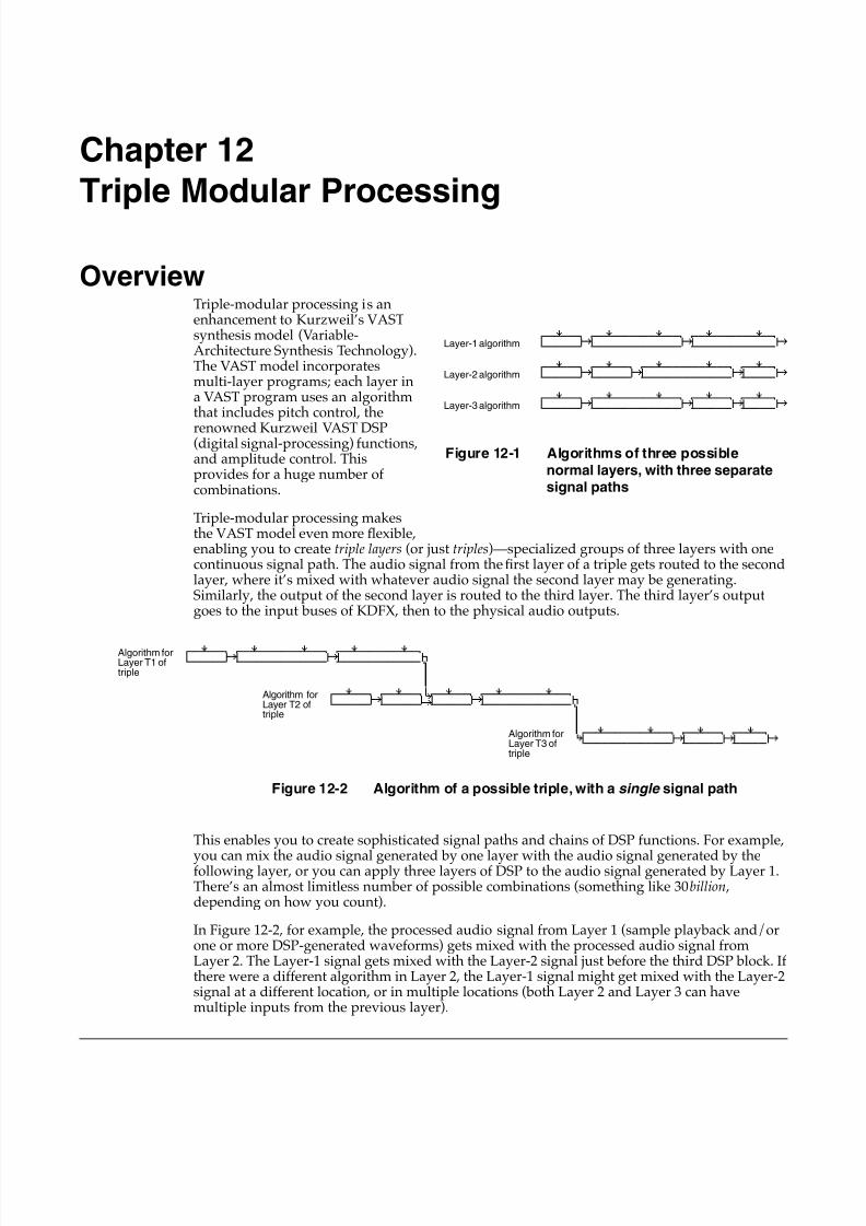
8/21/2019 MR_K2661
http://slidepdf.com/reader/full/mrk2661 341/499
Chapter 12
Triple Modular Processing
OverviewTriple-modular processing is anenhancement to Kurzweil’s VASTsynthesis model (Variable-Architecture Synthesis Technology).The VAST model incorporatesmulti-layer programs; each layer ina VAST program uses an algorithmthat includes pitch control, the
renowned Kurzweil VAST DSP(digital signal-processing) functions,and amplitude control. Thisprovides for a huge number ofcombinations.
Triple-modular processing makesthe VAST model even more flexible,enabling you to create triple layers (or just triples)—specialized groups of three layers with onecontinuous signal path. The audio signal from the first layer of a triple gets routed to the secondlayer, where it’s mixed with whatever audio signal the second layer may be generating.Similarly, the output of the second layer is routed to the third layer. The third layer’s outputgoes to the input buses of KDFX, then to the physical audio outputs.
This enables you to create sophisticated signal paths and chains of DSP functions. For example,
you can mix the audio signal generated by one layer with the audio signal generated by thefollowing layer, or you can apply three layers of DSP to the audio signal generated by Layer 1.There’s an almost limitless number of possible combinations (something like 30 billion ,depending on how you count).
In Figure 12-2 , for example, the processed audio signal from Layer 1 (sample playback and/orone or more DSP-generated waveforms) gets mixed with the processed audio signal fromLayer 2. The Layer-1 signal gets mixed with the Layer-2 signal just before the third DSP block. Ifthere were a different algorithm in Layer 2, the Layer-1 signal might get mixed with the Layer-2signal at a different location, or in multiple locations (both Layer 2 and Layer 3 can havemultiple inputs from the previous layer).
qwwerwwtqwwerwwwwwwerwwtqwwerwwwwwwerwtd gk gk ghCVVVVVVBCVVVVVVVVVVVVVVBCVVVVVVVVVVVVVB
qwwerwwtqwwerwwtqwwerwwwwwwerwwtqwwerwtd gk gk gk ghCVVVVVVBCVVVVVVBCVVVVVVVVVVVVVVBCVVVVVB
qwwerwwtqwwerwwwwwwerwwtqwwerwwtqwwerwtd gk gk gk ghCVVVVVVBCVVVVVVVVVVVVVVBCVVVVVVBCVVVVVB
Layer-1 algorithm
Layer-2 algorithm
Layer-3 algorithm
Figure 12-1 Algorithms of three possible
normal layers, with three separatesignal paths
Algorithm forLayer T3 oftriple
Algorithm forLayer T2 oftriple
Algorithm forLayer T1 oftriple
qwwerwwtqwwerwwwwwwerwwtqwwerwwwwwwerwtd gk gk jCVVVVVVBCVVVVVVVVVVVVVVBCVVVVVVVVVVVVVM
qwwerwwtqwwerwwt7wwerwwtqwwerwwwwwwerwwtd gk i; gk jCVVVVVVBCVVVVVVBNVVVVVVBCVVVVVVVVVVVVVVM
qwwerwwwwwwerwwtqwwerwwtqwwerwtK gk gk ghCVVVVVVVVVVVVVVBCVVVVVVBCVVVVVB
Figure 12-2 Algorithm of a possible triple, with a single signal path
8/21/2019 MR_K2661
http://slidepdf.com/reader/full/mrk2661 342/499
12-2
Triple Modular Processing
Overview
Note that any processing in Layer 2 that’s “downstream” (to the right) of the input(s) fromLayer 1 gets applied to the signals from both Layer 1 and Layer 2. After the processing inLayer 2, the signal passes to Layer 3 for still more processing before going to KDFX.
Any non-KB3 program can contain a triple, alone or in combination with normal layers and/orother triples (KB3 programs don’t use layers, so they can’t contain triples). Each triple is acontiguous set of three otherwise normal layers, with all the usual layer parameters. Becausetheir audio paths are linked, the layers of a triple are always numbered consecutively. You can’treorder the layers within a triple, but you can locate the triple anywhere within a program. Forexample, a ten-layer program might contain two triples: one triple spanning Layers 2–4 and theother spanning Layers 7–9 (with Layers 1, 5, 6, and 10 being normal layers).
Triples and PolyphonyEach triple uses three voices, the equivalent of three normal layers. By using a triple instead ofthree normal layers, you add millions of sound-editing possibilities without using any morevoices. If you play enough notes to exceed the K2661’s polyphonic limit, the three voices used byeach triple get stolen as a unit, according to the priority set by the parameters on the AMPENV
page of Layer 3 of the triple.
Soloing and MutingYou can solo and mute triples much as you can normal layers. Soloing and muting alwaysaffects the entire triple, however; you can’t solo or mute individual layers of a triple.
KB3 ProgramsYou can’t use triples in KB3 programs, since KB3 programs don’t use the VAST model. That is,they don’t consist of layers like non-KB3 programs (instead, every KB3 program plays notes thatare generated by tone wheels that start running as soon as you select the program).Consequently, KB3 programs can’t contain triples, because triples are specialized layers.
Even so, KB3 programs can coexist in setups with programs that use triples. Keep in mindthough, that since a typical KB3 program uses about 40 voices, any setup that uses one of theseprograms has only eight voices left over. This means that you might not always hear every noteof a setup that contains both a KB3 program and one or more programs containing a triple (ormultiple triples). Whenever a KB3 note is playing, the K2661 can play a maximum of two notesfrom triples.
Note: You can edit a KB3 program to reduce the number of tone wheels it uses, which frees up additionalvoices (one voice for every two tone wheels).
Live ModeLive Mode enables you to take an external audio signal and route it through the K2661’s VASTsound engine. (This works only if you have the Sampling Option installed in your K2661.)Triple-modular processing makes for an even greater number of possibilities in Live mode. Forexample, a triple can route a single Live-mode input through three layers of DSP, or it can mix aLive-mode input with an internally-generated K2661 sound. A triple can also mix two Live-mode inputs with each other and/or with an internally-generated K2661 sound.
8/21/2019 MR_K2661
http://slidepdf.com/reader/full/mrk2661 343/499
Triple Modular Processing
Overview
12-3
Algorithms for Triple Modular ProcessingThere are 94 new VAST algorithms, incorporating familiar Kurzweil DSP functions. Thealgorithms are divided into three sets, each of which correspond to a specific layer within thetriple. In other words, certain algorithms are available only for certain layers.
Layer-1 Algorithms: 33–62
There are 30 algorithms available for Layer 1 of any triple. The output of each of thesealgorithms is permanently configured to go to one or more inputs in a Layer-2 algorithm(63–100). All of these algorithms begin with pitch blocks, like the normal VAST algorithms. Thisensures that every triple has an audio signal.
Layer-2 Algorithms: 63–100
There are 38 algorithms available for Layer 2 of any triple. The output of each of thesealgorithms is permanently configured to go to one or more inputs in a Layer-3 algorithm(101–127).
Some of the Layer-2 algorithms (63–80) begin with pitch blocks, and some (81–100) do not.Layers that use algorithms 81–100 don’t make use of the parameters on the PITCH page in theProgram Editor.
Layer-3 Algorithms: 101–126
There are 26 algorithms available for Layer 3 of any triple. The output of each of thesealgorithms is permanently configured to go to the input of KDFX. None of these algorithms hasa pitch block, so layers that use them don’t make use of the parameters on the PITCH page in theProgram Editor.
Algorithm Reference
Turn to page 12-12 for diagrams of each algorithm, including the DSP functions available foreach block in each algorithm.
Compatibility with Other Kurzweil InstrumentsK2000s and K2500s (as well as all earlier models) can’t load programs that contain triples, sincethey don’t have the software required to support triples. Similarly, you can’t load programscontaining triples into K2600s with operating system versions earlier than v2.0.
8/21/2019 MR_K2661
http://slidepdf.com/reader/full/mrk2661 344/499
12-4
Triple Modular Processing
Creating Triples
Creating TriplesThere are several ways to add a triple to a program. The most convenient method depends onwhat you want to do.
In case you’re wondering, there’s no way to convert a normal layer to a triple. Whenever youwant to create a program containing a triple, or add a triple to a program, use one of thefollowing methods.
Creating a New Triple
Creating a new triple inserts a copy of Layers 1–3 of Program 739 into the current program. Thisenables you to use Program 739 as a template for triples.
1. While in Program mode, select the program in which you want to create a triple.
2. Press Edit to enter the Program Editor.
3. Press <more , then press NewLyr. This displays a prompt asking you whether to create anormal layer or a triple.
4. Press Triple. The K2661 creates the triple, adding three linked layers after the highest-numbered existing layer (for example, if the program contained three layers, the newtriple would occupy Layers 4–6). Adding the triple takes a few seconds; the display showsyou the K2661’s progress).
5. Rename and/or save the program as desired.
If you want to use one of your own triples as the template, edit the triple in Program 739 , thensave the program with ID 739 (this creates a RAM version of the program, temporarilyoverwriting the ROM version—you can restore the ROM version by deleting Program 739 ,which erases the RAM version).
Copying a Program Containing a Triple
This method works well when you want to make a few relatively simple adjustments to anexisting program (without changing the original): changing keymaps, using a differentKDFX studio, tweaking an amplitude envelope, or adjusting one or more DSP blocks in thetriple itself.
1. While in Program mode, select the program you want to copy.
2. Press Edit to enter the Program Editor.
3. Press <more until you see the Name soft button.
4. Press Name , rename the program, and press OK.
5. Press Save , and save the program to a new ID (if you’re editing a RAM program, changethe ID to avoid replacing an existing program).
6. Edit the new program as desired.
As an alternative, you can use the Copy function in Master mode, as described in yourMusician’s Guide.
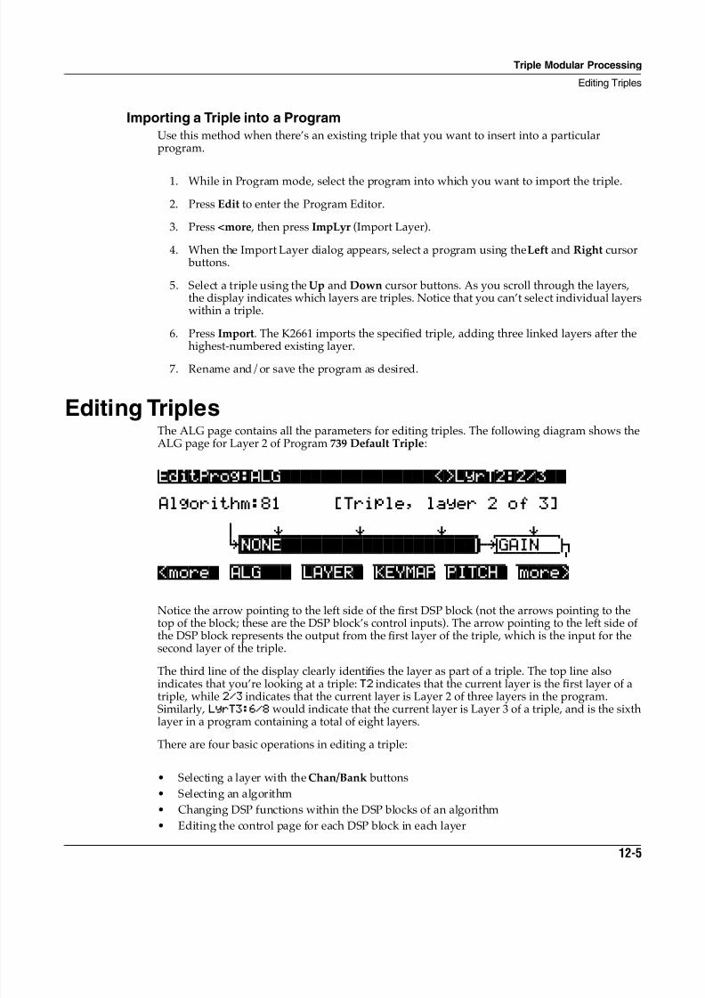
8/21/2019 MR_K2661
http://slidepdf.com/reader/full/mrk2661 345/499
Triple Modular Processing
Editing Triples
12-5
Importing a Triple into a Program
Use this method when there’s an existing triple that you want to insert into a particularprogram.
1. While in Program mode, select the program into which you want to import the triple.
2. Press Edit to enter the Program Editor.
3. Press <more , then press ImpLyr (Import Layer).
4. When the Import Layer dialog appears, select a program using the Left and Right cursor buttons.
5. Select a triple using the Up and Down cursor buttons. As you scroll through the layers,the display indicates which layers are triples. Notice that you can’t select individual layerswithin a triple.
6. Press Import. The K2661 imports the specified triple, adding three linked layers after the
highest-numbered existing layer.7. Rename and/or save the program as desired.
Editing TriplesThe ALG page contains all the parameters for editing triples. The following diagram shows theALG page for Layer 2 of Program 739 Default Triple:
EditProg:ALG|||||||||||||||<>LyrT2:2/3|| Algorithm:81 [Triple, layer 2 of 3]
6 0WWWERWWWWWWERWWWWWWERWWTqwwwerwt
KNONE|||||||||||||||||||©kGAIN j cvvvvvVvvvvvvVvvvvvvVvvvbcvVvvvvm<more| ALG||| LAYER| KEYMAP PITCH| more>
Notice the arrow pointing to the left side of the first DSP block (not the arrows pointing to thetop of the block; these are the DSP block’s control inputs). The arrow pointing to the left side ofthe DSP block represents the output from the first layer of the triple, which is the input for thesecond layer of the triple.
The third line of the display clearly identifies the layer as part of a triple. The top line alsoindicates that you’re looking at a triple: T2 indicates that the current layer is the first layer of a
triple, while 2/3 indicates that the current layer is Layer 2 of three layers in the program.Similarly, LyrT3:6/8 would indicate that the current layer is Layer 3 of a triple, and is the sixthlayer in a program containing a total of eight layers.
There are four basic operations in editing a triple:
• Selecting a layer with the Chan/Bank buttons
• Selecting an algorithm
• Changing DSP functions within the DSP blocks of an algorithm
• Editing the control page for each DSP block in each layer
8/21/2019 MR_K2661
http://slidepdf.com/reader/full/mrk2661 346/499
12-6
Triple Modular Processing
Editing Triples
The parameters on the ALG page consist of the algorithm itself, and the DSP blocks within thealgorithm (In the diagram, the second DSP block in the algorithm is selected). Use the cursor buttons to select the parameters, and a data entry method to change the value of the selectedparameter.
Amplitude EnvelopesA layer’s amplitude envelope is a critical element of the layer’s sound; it determines the layer’sattack, decay, and release times—among other things. These features are controlled in one oftwo ways: by default settings stored in a layer’s keymap, or by the settings for the parameterson the layer’s AMPENV page.
The amplitude envelope gets applied to a layer’s audio signal as it passes through thealgorithm’s AMP block (if it contains one). All the normal VAST algorithms (1–31) end with anAMP block, so normal VAST layers always use an amplitude envelope. This isn’t true for alltriple algorithms, however.
All the Layer-3 algorithms (101–126) end with AMP blocks, which ensures that there’s at least
one amplitude envelope for every triple. For Layers 1 and 2 of a triple, the AMP block isoptional. To include an AMP block in an algorithm, assign a value of AMP in any one-stage DSP block from F1 to F4 (the PITCH block, if the layer contains one, has a fixed value).
It’s important to keep in mind that whatever happens in the amplitude envelops in Layers 1and 2 of a triple, the amplitude envelope in layer 3 affects the sound of the entire triple. Forexample, if you have a long release in the amplitude envelope in Layer 1, but a short release inthe amplitude envelope in Layer 3, Layer 1’s release will continue only as long as Layer 3’srelease
AMP Blocks in Layers 1 and 2 of a Triple
When you put an AMP block in Layer 1 or 2 of a triple, that layer uses its own amplitudeenvelope, as specified on the layer’s AMPENV page. This envelope affects only its own layer,
and not the subsequent layers in the triple. Also, amplitude envelopes (if any) applied toLayers 1 and 2 don’t apply MIDI volume data; only the amplitude envelope in Layer 3 controlsoverall volume.
A layer that doesn’t contain an AMP block ignores its own amplitude envelope. So, for example,if Layer 1 of a triple has no AMP block, Layer 1’s output has no amplitude envelope. As thesignal from Layer 1 mixes with the signal from Layer 2, the amplitude envelope from Layer 2, ifany, may affect the sound from Layer 1 (this depends on Layer 2’s inputs—see Input Locations onpage 12-7.
When to Use AMP Blocks in Layers 1 and 2
Put an AMP block in Layer 1 or Layer 2 whenever you want that layer to use its own amplitudeenvelope. This affects the layer’s sound to varying degrees, depending on two things: the
keymap assigned to the layer, and the mode (Natural or User) of the layer’s AMPENV.
AMP blocks can be particularly important in Layers 1 and 2 when those layers use keymaps thatcontain ROM samples or edited versions of ROM samples (especially samples of acousticsounds like piano or strings). That’s because the factory-default (natural) amplitude envelopesof many of these keymaps also control the decompression of the keymap’s samples (tomaximize audio quality, many samples are stored in compressed form, and are decompressed just before playback). If there’s no AMP block, there’s no amplitude envelope, and therefore nodecompression information. This can alter the sound of a ROM sample drastically.
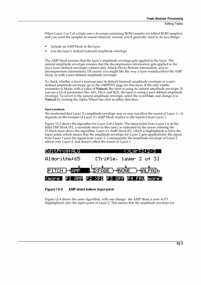
8/21/2019 MR_K2661
http://slidepdf.com/reader/full/mrk2661 347/499
Triple Modular Processing
Editing Triples
12-7
When Layer 1 or 2 of a triple uses a keymap containing ROM samples (or edited ROM samples),and you want the samples to sound relatively normal, you’ll generally need to do two things:
• Include an AMP block in the layer
• Use the layer’s default (natural) amplitude envelope
The AMP block ensures that the layer’s amplitude envelope gets applied to the layer. Thenatural amplitude envelope ensures that the decompression information gets applied to thelayer (user-defined envelopes contain only Attack-Decay-Release information, and nodecompression information). Of course, you might like the way a layer sounds without the AMP block, or with a user-defined amplitude envelope.
To check whether a layer’s keymap uses its default (natural) amplitude envelope or a user-defined amplitude envelope, go to the AMPENV page for that layer. If the only visibleparameter is Mode, with a value of Natural , the layer is using its natural amplitude envelope. Ifyou see a lot of parameters like Att1, Dec1, and Rel1, the layer is using a user-defined amplitudeenvelope. To revert to the natural amplitude envelope, select the word User , and change it to
Natural by turning the Alpha Wheel one click in either direction.
Input Locations
We mentioned that Layer 2’s amplitude envelope may or may not affect the sound of Layer 1—itdepends on the location of Layer 2’s AMP block relative to the input(s) from Layer 1.
Figure 12-3 shows the algorithm for Layer 2 of a triple. The input point from Layer 1 is in thethird DSP block (F2, a crossfade mixer in this case), as indicated by the arrow entering theF2 block from above the algorithm. Layer 2’s AMP block (F1, which is highlighted) is before theinput point, which means that the amplitude envelope for Layer 2 gets applied before the signalfrom Layer 1 joins the signal from Layer 2. Consequently the amplitude envelope of Layer 2affects only Layer 2, and doesn’t affect the sound of Layer 1.
EditProg:ALG|||||||||||||||<>LyrT2:2/3|| Algorithm:65 [Triple, layer 2 of 3]
6 qwwwwwwtqWWERWWT7wwerwwtqwwerwwtqwwerwt dPITCH gkAMP|||I;XFADE gkNONE gkALPASj cvvvvvVbcvvvvVvbnvvvVvvbcvvVvvvbcvVvvvm<more| F1|AMP F2|XFD F3|OFF F4|FRQ more>
Figure 12-3 AMP block before input point
Figure 12-4 shows the same algorithm, with one change: the AMP block is now in F3(highlighted), after the input point of Layer 2. This means that the amplitude envelope for
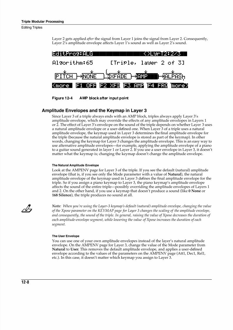
8/21/2019 MR_K2661
http://slidepdf.com/reader/full/mrk2661 348/499
12-8
Triple Modular Processing
Editing Triples
Layer 2 gets applied after the signal from Layer 1 joins the signal from Layer 2. Consequently,Layer 2’s amplitude envelope affects Layer 1’s sound as well as Layer 2’s sound.
EditProg:ALG|||||||||||||||<>LyrT2:2/3||
Algorithm:65 [Triple, layer 2 of 3]
6 qwwerwwtqwwerwwt7wwerwwtqWWERWWTqwwerwt dPITCH gkNONE i;XFADE gkAMP|||©kALPASj cvvvvvVbcvvvvVvbnvvvVvvbcvvVvvvbcvVvvvm<more| F1|OFF F2|XFD F3|AMP F4|FRQ more>
Figure 12-4 AMP block after input point
Amplitude Envelopes and the Keymap in Layer 3
Since Layer 3 of a triple always ends with an AMP block, triples always apply Layer 3’samplitude envelope, which may override the effects of any amplitude envelopes in Layers 1or 2. The effect of Layer 3’s envelope on the sound of the triple depends on whether Layer 3 usesa natural amplitude envelope or a user-defined one. When Layer 3 of a triple uses a naturalamplitude envelope, the keymap used in Layer 3 determines the final amplitude envelope forthe triple (because the natural amplitude envelope is stored as part of the keymap). In otherwords, changing the keymap for Layer 3 changes the amplitude envelope. This is an easy way touse alternative amplitude envelopes—for example, applying the amplitude envelope of a pianoto a guitar sound generated in layer 1 or Layer 2. If you use a user envelope in Layer 3, it doesn’tmatter what the keymap is; changing the keymap doesn’t change the amplitude envelope.
The Natural Amplitude Envelope
Look at the AMPENV page for Layer 3 of the triple. If you see the default (natural) amplitude
envelope (that is, if you see only the Mode parameter with a value of Natural), the naturalamplitude envelope of the keymap used in Layer 3 defines the final amplitude envelope for thetriple. So if you assign a piano keymap to Layer 3, the piano keymap’s amplitude envelopeaffects the sound of the entire triple—possibly overriding the amplitude envelopes of Layers 1and 2. On the other hand, if you use a keymap that doesn’t produce a sound (like 0 None or168 Silence), the triple produces no sound at all.
Note: When you’re using the Layer-3 keymap’s default (natural) amplitude envelope, changing the valueof the Xpose parameter on the KEYMAP page for Layer 3 changes the scaling of the amplitude envelope,and consequently, the sound of the triple. In general, raising the value of Xpose decreases the duration ofeach amplitude-envelope segment, while lowering the value of Xpose increases the duration of eachsegment.
The User Envelope
You can use one of your own amplitude envelopes instead of the layer’s natural amplitudeenvelope. On the AMPENV page for Layer 3, change the value of the Mode parameter fromNatural to User. This removes the default amplitude envelope, and applies a user-definedenvelope according to the values of the parameters on the AMPENV page (Att1, Dec1, Rel1,etc.). In this case, it doesn’t matter which keymap you assign to Layer 3.
8/21/2019 MR_K2661
http://slidepdf.com/reader/full/mrk2661 349/499
Triple Modular Processing
Editing Triples
12-9
Summary of Amplitude Envelopes in Triples
Because of the special nature of triples and their interactions with amplitude envelopes, you’llneed to give some thought to the amplitude.in each layer of the triples you program. There arethree primary points to remember, each of which significantly affects the sound of a triple:
• The optional use of AMP blocks in Layers 1 and 2 (which determines whether Layers 1and 2 use their own amplitude envelopes)
• The keymaps (if any) in each layer of a triple (which determine the sound produced by eachlayer)
• Choosing natural or user amplitude envelopes, especially in Layer 3
Other ConsiderationsTriples are a lot like normal layers, but there are a few important differences.
Processing-Only LayersLayers that use Algorithms 81–127 can be processing-only layers—that is, they can provideadditional processing for the audio output of other layers, without generating their own sounds.(They can provide additional processing and produce sound, as you’ll see.)
Layer 1 of a triple usually generates sound via sample playback (unless it uses Keymap 0 None or 168 Silence). In other words, the sample playback of Layer 1 is routed to the input ofLayer 1’s algorithm. Consequently Layer 1 doesn’t work as a processing-only layer. In additionto processing sample playback, most of the Layer-1 algorithms (33–62) can also generatewaveforms within the algorithms themselves, using DSP functions like SINE and SAW.
For some of the Layer-2 algorithms (63–80) the input is the sample playback from Layer 2,mixed at one or more points with the output from Layer 1. For the remainder of the Layer-2algorithms (81–100), the only input is the output from Layer 1; the sample playback from layer 2
(if any) is not routed to the inputs of these algorithms. Most of the Layer-2 algorithms can alsogenerate waveforms within the algorithms themselves.
The input for all of the Layer-3 algorithms is the output from Layer 2. These algorithms neverprocess the sample playback (if any) from Layer 3. Like the other algorithms, however, they cangenerate their own waveforms.
Since layers that use Algorithms 81–127 don’t process their own sample playback data, theyhave no pitch parameters, and their algorithm diagrams contain no pitch blocks. When you’reediting a layer that uses one of these algorithms, if you press the PITCH soft button, you’ll see a blank page.
Layer Parameters
Since a triple is essentially a single layer (except that it uses three voices per note), it has a singleset of layer parameters. You can view and edit these parameters by pressing the LAYER soft button when Layer 1 of the triple is current. If you press LAYER when Layer 2 or 3 is current,you see a blank page.
Output Parameters
Triples have a single set of output parameters controlling all three layers (again because triplesare essentially single layers). You can view and edit the output parameters by pressing theOUTPUT soft button when Layer 3 of the triple is current. If you press OUTPUT when Layer 1or 2 is current, you see a blank page.
8/21/2019 MR_K2661
http://slidepdf.com/reader/full/mrk2661 350/499
12-10
Triple Modular Processing
Editing Triples
New Combinations of DSP Functions
Seven new two-stage DSP functions combine a filter or double shaper with a gain function (thegain occurs after the filtering/shaping). One or more of these functions is available in most of thetwo-stage DSP blocks. They’re listed below.
These functions are equivalent to two single-stage blocks in a v1.0 algorithm—a block using afilter or shaper followed by a block using the GAIN function.
Stereo Keymaps
Because of sound-processing requirements, triples can’t use stereo keymaps. Consequently,there’s no Stereo parameter on the Keymap page when any layer of a triple is the current layer.Programs that use both triples and normal layers can use stereo keymaps for the normal layers.
Note Stealing in Triples
When you exceed the 48-voice polyphonic limit, the K2661 uses the AMPENV-page settings forLayer 3 of a triple to determine how the voices from that triple get stolen. Consequently, if youwant to change how the triple’s notes get stolen, you should edit the parameters on theAMPENV page for Layer 3 of the triple (as opposed to editing the AMPENV parameters forLayers 1 or 2). For example, decreasing the duration of the decay and/or release segmentsreduces your polyphony requirements.
Using DSP WaveformsKeep in mind that the DSP waveforms (like SINE, SQR, SAW, and NOISE are typically 5 to 6 dBhotter than ROM samples. This can cause clipping in some of the filters used in triplealgorithms. Consequently, you may want to reduce the input levels for filters that are processingDSP waveforms.
Using PWM
DSP blocks that use the PWM function are meant to be followed by blocks using the DISTfunction (this is true for normal VAST layers, as well). See your Musician’s Guide for moreinformation.
Using NOISE+The DSP function called NOISE+ is available for many one-stage DSP blocks in Layer-2 andLayer-3 algorithms. This provides a convenient way to add noise at one or more points in atriple. When you use this function in a DSP block, it adds nearly-white noise—that is, an audiosignal with nearly equal amplitude at all audible frequencies—to the existing signal (unless theexisting signal has zero amplitude, in which case no noise gets added).
LOPAS2 GAIN LP2RES GAIN
HIPAS2 GAIN SHAPE2 GAIN
BAND2 GAIN LPGATE GAIN
NOTCH2 GAIN
8/21/2019 MR_K2661
http://slidepdf.com/reader/full/mrk2661 351/499
Triple Modular Processing
Editing Triples
12-11
In order to function as designed, DSP blocks that use NOISE+ must be followed immediately byone of the DSP functions listed below. Otherwise, you won’t be able to attenuate the level of theadded noise. If you use NOISE+ in the last DSP block of a Layer-2 algorithm, the first DSP blockof Layer 3’s algorithm must be one of these functions.
Exploring the Possibilities
You may never exhaust the possible combinations of DSP functions available with triple-modular processing, but keep experimenting. We’ve found that using simple waveforms whentrying different DSP functions makes it easier to hear the effects of each function. Try usingSINE, SQR, and SAW in various DSP blocks. These block all incoming audio signals andgenerate a simple waveform as output (as opposed to SINE+, SQR+, and SAW+, which addwaveforms to the existing signal).
NONE +AMP
AMP +GAIN
PANNER XFADE
BAL AMP
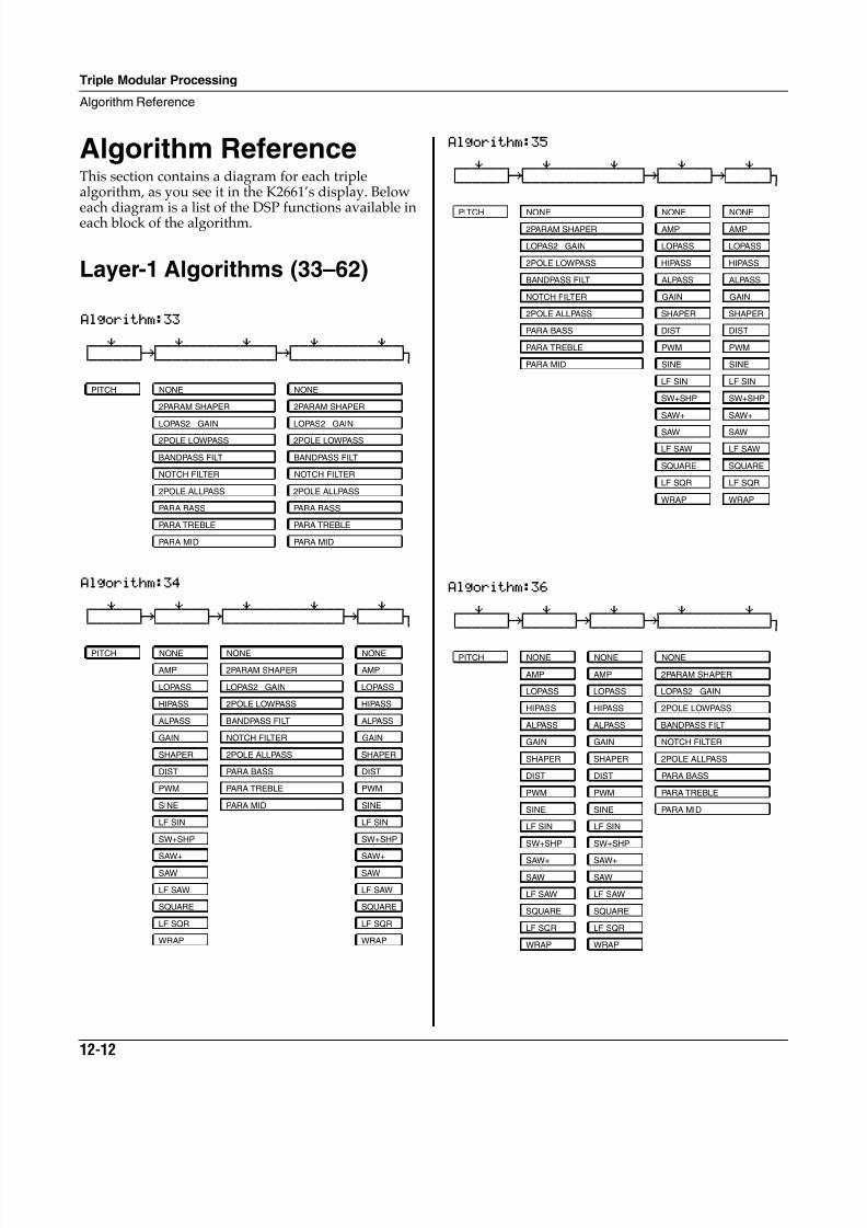
8/21/2019 MR_K2661
http://slidepdf.com/reader/full/mrk2661 352/499
12-12
Triple Modular Processing
Algorithm Reference
Algorithm ReferenceThis section contains a diagram for each triplealgorithm, as you see it in the K2661’s display. Below
each diagram is a list of the DSP functions available ineach block of the algorithm.
Layer-1 Algorithms (33–62)
Algorithm:33 qwwerwwtqwwerwwwwwwerwwtqwwerwwwwwwerwtd gk gk jCVVVVVVBCVVVVVVVVVVVVVVBCVVVVVVVVVVVVVM
Algorithm:34 qwwerwwtqwwerwwtqwwerwwwwwwerwwtqwwerwtd gk gk gk jCVVVVVVBCVVVVVVBCVVVVVVVVVVVVVVBCVVVVVM
PITCH NONE NONE
2PARAM SHAPER 2PARAM SHAPER
LOPAS2 GAIN LOPAS2 GAIN
2POLE LOWPASS 2POLE LOWPASS
BANDPASS FILT BANDPASS FILT
NOTCH FILTER NOTCH FILTER
2POLE ALLPASS 2POLE ALLPASS
PARA BASS PARA BASS
PARA TREBLE PARA TREBLE
PARA MID PARA MID
PITCH NONE NONE NONE
AMP 2PARAM SHAPER AMP
LOPASS LOPAS2 GAIN LOPASS
HIPASS 2POLE LOWPASS HIPASS
ALPASS BANDPASS FILT ALPASS
GAIN NOTCH FILTER GAIN
SHAPER 2POLE ALLPASS SHAPER
DIST PARA BASS DIST
PWM PARA TREBLE PWM
SINE PARA MID SINE
LF SIN LF SIN
SW+SHP SW+SHP
SAW+ SAW+SAW SAW
LF SAW LF SAW
SQUARE SQUARE
LF SQR LF SQR
WRAP WRAP
Algorithm:35 qwwerwwtqwwerwwwwwwerwwtqwwerwwtqwwerwtd gk gk gk jCVVVVVVBCVVVVVVVVVVVVVVBCVVVVVVBCVVVVVM
Algorithm:36 qwwerwwtqwwerwwtqwwerwwtqwwerwwwwwwerwtd gk gk gk jCVVVVVVBCVVVVVVBCVVVVVVBCVVVVVVVVVVVVVM
PITCH NONE NONE NONE
2PARAM SHAPER AMP AMP
LOPAS2 GAIN LOPASS LOPASS
2POLE LOWPASS HIPASS HIPASS
BANDPASS FILT ALPASS ALPASS
NOTCH FILTER GAIN GAIN
2POLE ALLPASS SHAPER SHAPER
PARA BASS DIST DIST
PARA TREBLE PWM PWM
PARA MID SINE SINE
LF SIN LF SIN
SW+SHP SW+SHP
SAW+ SAW+
SAW SAW
LF SAW LF SAW
SQUARE SQUARE
LF SQR LF SQR
WRAP WRAP
PITCH NONE NONE NONE
AMP AMP 2PARAM SHAPER
LOPASS LOPASS LOPAS2 GAIN
HIPASS HIPASS 2POLE LOWPASS
ALPASS ALPASS BANDPASS FILT
GAIN GAIN NOTCH FILTER
SHAPER SHAPER 2POLE ALLPASS
DIST DIST PARA BASS
PWM PWM PARA TREBLE
SINE SINE PARA MID
LF SIN LF SIN
SW+SHP SW+SHP
SAW+ SAW+
SAW SAW
LF SAW LF SAW
SQUARE SQUARE
LF SQR LF SQR
WRAP WRAP
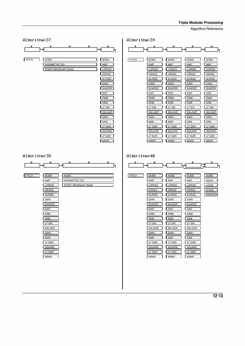
8/21/2019 MR_K2661
http://slidepdf.com/reader/full/mrk2661 353/499
Triple Modular Processing
Algorithm Reference
12-13
Algorithm:37 qwwerwwtqwwerwwwwwwerwwwwwwerwwtqwwerwtd gk gk jCVVVVVVBCVVVVVVVVVVVVVVVVVVVVVVBCVVVVVM
Algorithm:38 qwwerwwtqwwerwwtqwwerwwwwwwerwwwwwwerwtd gk gk jCVVVVVVBCVVVVVVBCVVVVVVVVVVVVVVVVVVVVVM
PITCH NONE NONE
PARAMETRIC EQ AMP
STEEP RESONANT BASS LOPASS
HIPASS
ALPASS
GAIN
SHAPER
DIST
PWM
SINE
LF SIN
SW+SHP
SAW+
SAW
LF SAW
SQUARE
LF SQR
WRAP
PITCH NONE NONE
AMP PARAMETRIC EQ
LOPASS STEEP RESONANT BASS
HIPASS
ALPASS
GAIN
SHAPER
DIST
PWM
SINE
LF SIN
SW+SHP
SAW+
SAW
LF SAW
SQUARE
LF SQR
WRAP
Algorithm:39 qwwerwwtqwwerwwtqwwerwwtqwwerwwtqwwerwtd gk gk gk gk jCVVVVVVBCVVVVVVBCVVVVVVBCVVVVVVBCVVVVVM
Algorithm:40 qwwerwwtqwwerwwtqwwerwwtqwwerwwt¥wwerwtd gk gk jk u: jCVVVVVVBCVVVVVVBCVVVVVVM<>>>>>>S?VVVVVM
PITCH NONE NONE NONE NONE
AMP AMP AMP AMP
LOPASS LOPASS LOPASS LOPASS
HIPASS HIPASS HIPASS HIPASS
ALPASS ALPASS ALPASS ALPASS
GAIN GAIN GAIN GAIN
SHAPER SHAPER SHAPER SHAPER
DIST DIST DIST DIST
PWM PWM PWM PWM
SINE SINE SINE SINE
LF SIN LF SIN LF SIN LF SIN
SW+SHP SW+SHP SW+SHP SW+SHP
SAW+ SAW+ SAW+ SAW+
SAW SAW SAW SAW
LF SAW LF SAW LF SAW LF SAW
SQUARE SQUARE SQUARE SQUARE
LF SQR LF SQR LF SQR LF SQR
WRAP WRAP WRAP WRAP
PITCH NONE NONE NONE NONE
AMP AMP AMP xGAIN
LOPASS LOPASS LOPASS +GAIN
HIPASS HIPASS HIPASS XFADE
ALPASS ALPASS ALPASS AMPMOD
GAIN GAIN GAIN
SHAPER SHAPER SHAPER
DIST DIST DIST
PWM PWM PWM
SINE SINE SINE
LF SIN LF SIN LF SIN
SW+SHP SW+SHP SW+SHP
SAW+ SAW+ SAW+
SAW SAW SAW
LF SAW LF SAW LF SAW
SQUARE SQUARE SQUARE
LF SQR LF SQR LF SQR
WRAP WRAP WRAP
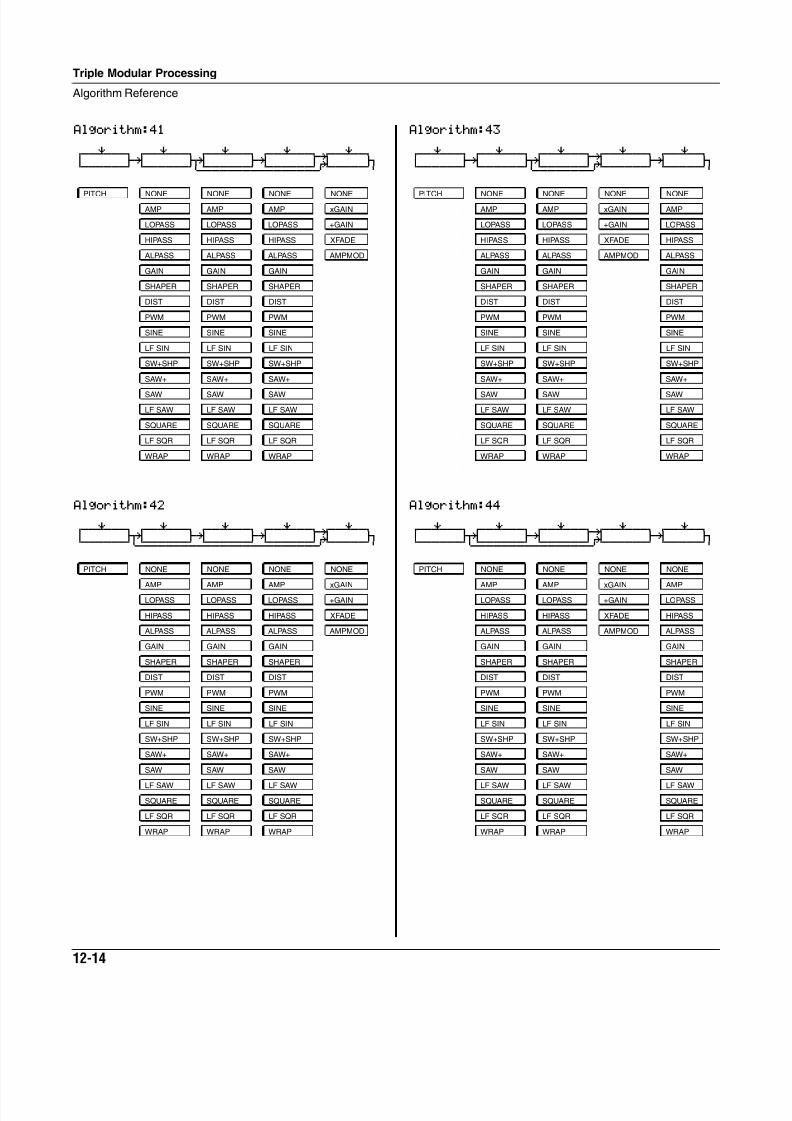
8/21/2019 MR_K2661
http://slidepdf.com/reader/full/mrk2661 354/499
12-14
Triple Modular Processing
Algorithm Reference
Algorithm:41 qwwerwwtqwwerwwtqwwerwwtqwwerwwt¥wwerwtd gk jk gk u: jCVVVVVVBCVVVVVVM<>>>>>>S<>>>>>>S?VVVVVM
Algorithm:42 qwwerwwtqwwerwwtqwwerwwtqwwerwwt¥wwerwtd jk gk gk u: jCVVVVVVM<>>>>>>S<>>>>>>S<>>>>>>S?VVVVVM
PITCH NONE NONE NONE NONE
AMP AMP AMP xGAIN
LOPASS LOPASS LOPASS +GAIN
HIPASS HIPASS HIPASS XFADE
ALPASS ALPASS ALPASS AMPMOD
GAIN GAIN GAIN
SHAPER SHAPER SHAPER
DIST DIST DIST
PWM PWM PWM
SINE SINE SINE
LF SIN LF SIN LF SIN
SW+SHP SW+SHP SW+SHP
SAW+ SAW+ SAW+
SAW SAW SAW
LF SAW LF SAW LF SAW
SQUARE SQUARE SQUARE
LF SQR LF SQR LF SQR
WRAP WRAP WRAP
Algorithm:43 qwwerwwtqwwerwwtqwwerwwt¥wwerwwtqwwerwtd gk jk u: gk jCVVVVVVBCVVVVVVM<>>>>>>S?VVVVVVBCVVVVVM
Algorithm:44 qwwerwwtqwwerwwtqwwerwwt¥wwerwwtqwwerwtd jk gk u: gk jCVVVVVVM<>>>>>>S<>>>>>>S?VVVVVVBCVVVVVM
PITCH NONE NONE NONE NONE
AMP AMP xGAIN AMP
LOPASS LOPASS +GAIN LOPASS
HIPASS HIPASS XFADE HIPASS
ALPASS ALPASS AMPMOD ALPASS
GAIN GAIN GAIN
SHAPER SHAPER SHAPER
DIST DIST DIST
PWM PWM PWM
SINE SINE SINE
LF SIN LF SIN LF SIN
SW+SHP SW+SHP SW+SHP
SAW+ SAW+ SAW+
SAW SAW SAW
LF SAW LF SAW LF SAW
SQUARE SQUARE SQUARE
LF SQR LF SQR LF SQR
WRAP WRAP WRAP
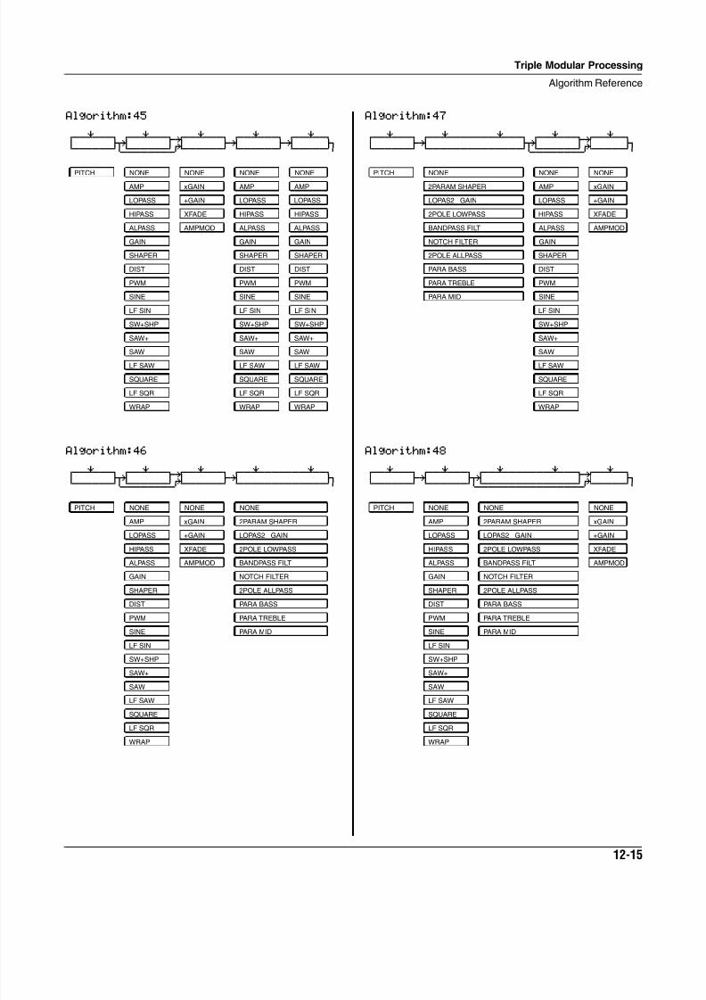
8/21/2019 MR_K2661
http://slidepdf.com/reader/full/mrk2661 355/499
Triple Modular Processing
Algorithm Reference
12-15
Algorithm:45 qwwerwwtqwwerwwt¥wwerwwtqwwerwwtqwwerwtd jk u: gk gk jCVVVVVVM<>>>>>>S?VVVVVVBCVVVVVVBCVVVVVM
Algorithm:46 qwwerwwtqwwerwwt¥wwerwwtqwwerwwwwwwerwtd jk u: gk jCVVVVVVM<>>>>>>S?VVVVVVBCVVVVVVVVVVVVVM
PITCH NONE NONE NONE NONE
AMP xGAIN AMP AMP
LOPASS +GAIN LOPASS LOPASS
HIPASS XFADE HIPASS HIPASS
ALPASS AMPMOD ALPASS ALPASS
GAIN GAIN GAIN
SHAPER SHAPER SHAPER
DIST DIST DIST
PWM PWM PWM
SINE SINE SINE
LF SIN LF SIN LF SIN
SW+SHP SW+SHP SW+SHP
SAW+ SAW+ SAW+
SAW SAW SAW
LF SAW LF SAW LF SAW
SQUARE SQUARE SQUARE
LF SQR LF SQR LF SQR
WRAP WRAP WRAP
PITCH NONE NONE NONE
AMP xGAIN 2PARAM SHAPER
LOPASS +GAIN LOPAS2 GAIN
HIPASS XFADE 2POLE LOWPASS
ALPASS AMPMOD BANDPASS FILT
GAIN NOTCH FILTER
SHAPER 2POLE ALLPASS
DIST PARA BASS
PWM PARA TREBLE
SINE PARA MID
LF SIN
SW+SHP
SAW+
SAW
LF SAW
SQUARE
LF SQR
WRAP
Algorithm:47 qwwerwwtqwwerwwwwwwerwwtqwwerwwt¥wwerwtd gk jk u: jCVVVVVVBCVVVVVVVVVVVVVVM<>>>>>>S?VVVVVM
Algorithm:48 qwwerwwtqwwerwwtqwwerwwwwwwerwwt¥wwerwtd gk jk u: jCVVVVVVBCVVVVVVM<>>>>>>>>>>>>>>S?VVVVVM
PITCH NONE NONE NONE
2PARAM SHAPER AMP xGAIN
LOPAS2 GAIN LOPASS +GAIN
2POLE LOWPASS HIPASS XFADE
BANDPASS FILT ALPASS AMPMOD
NOTCH FILTER GAIN
2POLE ALLPASS SHAPER
PARA BASS DIST
PARA TREBLE PWM
PARA MID SINE
LF SIN
SW+SHP
SAW+
SAW
LF SAW
SQUARE
LF SQR
WRAP
PITCH NONE NONE NONE
AMP 2PARAM SHAPER xGAIN
LOPASS LOPAS2 GAIN +GAIN
HIPASS 2POLE LOWPASS XFADE
ALPASS BANDPASS FILT AMPMOD
GAIN NOTCH FILTER
SHAPER 2POLE ALLPASS
DIST PARA BASS
PWM PARA TREBLE
SINE PARA MID
LF SIN
SW+SHP
SAW+
SAW
LF SAW
SQUARE
LF SQR
WRAP
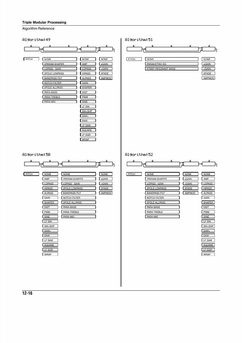
8/21/2019 MR_K2661
http://slidepdf.com/reader/full/mrk2661 356/499
12-16
Triple Modular Processing
Algorithm Reference
Algorithm:49 qwwerwwtqwwerwwwwwwerwwtqwwerwwt¥wwerwtd jk gk u: jCVVVVVVM<>>>>>>>>>>>>>>S<>>>>>>S?VVVVVM
Algorithm:50 qwwerwwtqwwerwwtqwwerwwwwwwerwwt¥wwerwtd jk gk u: jCVVVVVVM<>>>>>>S<>>>>>>>>>>>>>>S?VVVVVM
PITCH NONE NONE NONE
2PARAM SHAPER AMP xGAIN
LOPAS2 GAIN LOPASS +GAIN
2POLE LOWPASS HIPASS XFADE
BANDPASS FILT ALPASS AMPMOD
NOTCH FILTER GAIN
2POLE ALLPASS SHAPER
PARA BASS DIST
PARA TREBLE PWM
PARA MID SINE
LF SIN
SW+SHP
SAW+
SAW
LF SAW
SQUARE
LF SQR
WRAP
PITCH NONE NONE NONE
AMP 2PARAM SHAPER xGAIN
LOPASS LOPAS2 GAIN +GAIN
HIPASS 2POLE LOWPASS XFADE
ALPASS BANDPASS FILT AMPMOD
GAIN NOTCH FILTER
SHAPER 2POLE ALLPASS
DIST PARA BASS
PWM PARA TREBLE
SINE PARA MID
LF SIN
SW+SHP
SAW+
SAW
LF SAW
SQUARE
LF SQR
WRAP
Algorithm:51 qwwerwwtqwwerwwwwwwerwwwwwwerwwt¥wwerwtd jk u: jCVVVVVVM<>>>>>>>>>>>>>>>>>>>>>>S?VVVVVM
Algorithm:52 qwwerwwtqwwerwwwwwwerwwt¥wwerwwtqwwerwtd jk u: gk jCVVVVVVM<>>>>>>>>>>>>>>S?VVVVVVBCVVVVVM
PITCH NONE NONE
PARAMETRIC EQ xGAIN
STEEP RESONANT BASS +GAIN
XFADE
AMPMOD
PITCH NONE NONE NONE
2PARAM SHAPER xGAIN AMP
LOPAS2 GAIN +GAIN LOPASS
2POLE LOWPASS XFADE HIPASS
BANDPASS FILT AMPMOD ALPASS
NOTCH FILTER GAIN
2POLE ALLPASS SHAPER
PARA BASS DIST
PARA TREBLE PWM
PARA MID SINE
LF SIN
SW+SHP
SAW+
SAW
LF SAW
SQUARE
LF SQR
WRAP
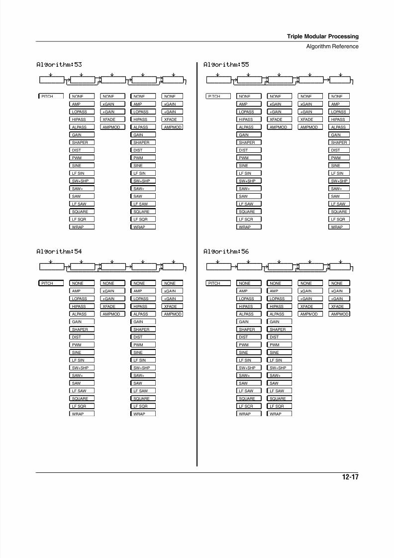
8/21/2019 MR_K2661
http://slidepdf.com/reader/full/mrk2661 357/499
Triple Modular Processing
Algorithm Reference
12-17
Algorithm:53 qwwerwwtqwwerwwt¥wwerwwtqwwerwwt¥wwerwtd jk u: jk u: jCVVVVVVM<>>>>>>S?VVVVVVM<>>>>>>S?VVVVVM
Algorithm:54 qwwerwwtqwwerwwt¥wwerwwtqwwerwwt¥wwerwtd jk u: gk u: jCVVVVVVM<>>>>>>S¿>>>>>>S<>>>>>>S?VVVVVM
PITCH NONE NONE NONE NONE
AMP xGAIN AMP xGAIN
LOPASS +GAIN LOPASS +GAIN
HIPASS XFADE HIPASS XFADE
ALPASS AMPMOD ALPASS AMPMOD
GAIN GAIN
SHAPER SHAPER
DIST DIST
PWM PWM
SINE SINE
LF SIN LF SIN
SW+SHP SW+SHP
SAW+ SAW+
SAW SAW
LF SAW LF SAW
SQUARE SQUARE
LF SQR LF SQR
WRAP WRAP
PITCH NONE NONE NONE NONE
AMP xGAIN AMP xGAIN
LOPASS +GAIN LOPASS +GAIN
HIPASS XFADE HIPASS XFADE
ALPASS AMPMOD ALPASS AMPMOD
GAIN GAIN
SHAPER SHAPER
DIST DIST
PWM PWM
SINE SINE
LF SIN LF SIN
SW+SHP SW+SHP
SAW+ SAW+
SAW SAW
LF SAW LF SAW
SQUARE SQUARE
LF SQR LF SQR
WRAP WRAP
Algorithm:55 qwwerwwtqwwerwwt¥wwerwwt¥wwerwwtqwwerwtd jk u: u: gk jCVVVVVVM<>>>>>>S¿>>>>>>S?VVVVVVBCVVVVVM
Algorithm:56 qwwerwwtqwwerwwtqwwerwwt¥wwerwwt¥wwerwtd gk jk u: u: jCVVVVVVBCVVVVVVM<>>>>>>S¿>>>>>>S?VVVVVM
PITCH NONE NONE NONE NONE
AMP xGAIN xGAIN AMP
LOPASS +GAIN +GAIN LOPASS
HIPASS XFADE XFADE HIPASS
ALPASS AMPMOD AMPMOD ALPASS
GAIN GAIN
SHAPER SHAPER
DIST DIST
PWM PWM
SINE SINE
LF SIN LF SIN
SW+SHP SW+SHP
SAW+ SAW+
SAW SAW
LF SAW LF SAW
SQUARE SQUARE
LF SQR LF SQR
WRAP WRAP
PITCH NONE NONE NONE NONE
AMP AMP xGAIN xGAIN
LOPASS LOPASS +GAIN +GAIN
HIPASS HIPASS XFADE XFADE
ALPASS ALPASS AMPMOD AMPMOD
GAIN GAIN
SHAPER SHAPER
DIST DIST
PWM PWM
SINE SINE
LF SIN LF SIN
SW+SHP SW+SHP
SAW+ SAW+
SAW SAW
LF SAW LF SAW
SQUARE SQUARE
LF SQR LF SQR
WRAP WRAP
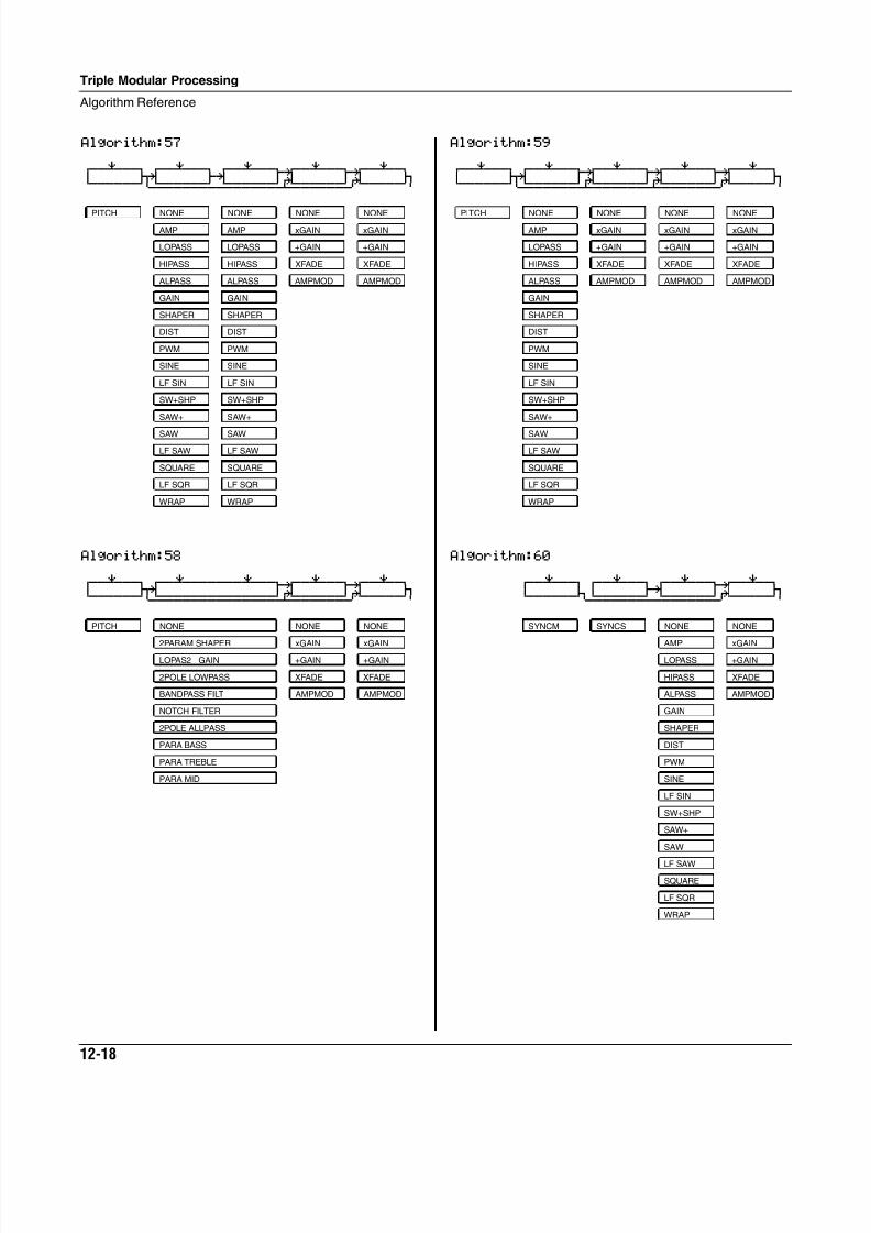
8/21/2019 MR_K2661
http://slidepdf.com/reader/full/mrk2661 358/499
12-18
Triple Modular Processing
Algorithm Reference
Algorithm:57 qwwerwwtqwwerwwtqwwerwwt¥wwerwwt¥wwerwtd jk gk u: u: jCVVVVVVM<>>>>>>S<>>>>>>S¿>>>>>>S?VVVVVM
Algorithm:58 qwwerwwtqwwerwwwwwwerwwt¥wwerwwt¥wwerwtd jk u: u: jCVVVVVVM<>>>>>>>>>>>>>>S¿>>>>>>S?VVVVVM
PITCH NONE NONE NONE NONE
AMP AMP xGAIN xGAIN
LOPASS LOPASS +GAIN +GAIN
HIPASS HIPASS XFADE XFADE
ALPASS ALPASS AMPMOD AMPMOD
GAIN GAIN
SHAPER SHAPER
DIST DIST
PWM PWM
SINE SINE
LF SIN LF SIN
SW+SHP SW+SHP
SAW+ SAW+
SAW SAW
LF SAW LF SAW
SQUARE SQUARE
LF SQR LF SQR
WRAP WRAP
PITCH NONE NONE NONE
2PARAM SHAPER xGAIN xGAIN
LOPAS2 GAIN +GAIN +GAIN
2POLE LOWPASS XFADE XFADE
BANDPASS FILT AMPMOD AMPMOD
NOTCH FILTER
2POLE ALLPASS
PARA BASS
PARA TREBLE
PARA MID
Algorithm:59 qwwerwwtqwwerwwt¥wwerwwt¥wwerwwt¥wwerwtd jk u: u: u: jCVVVVVVM<>>>>>>S¿>>>>>>S¿>>>>>>S?VVVVVM
Algorithm:60
qwwerwwtqwwerwwtqwwerwwt¥wwerwtd Jd gk u: jCVVVVVVM<>>>>>>S<>>>>>>S?VVVVVM
PITCH NONE NONE NONE NONE
AMP xGAIN xGAIN xGAIN
LOPASS +GAIN +GAIN +GAIN
HIPASS XFADE XFADE XFADE
ALPASS AMPMOD AMPMOD AMPMOD
GAIN
SHAPER
DIST
PWM
SINE
LF SIN
SW+SHP
SAW+
SAW
LF SAW
SQUARE
LF SQR
WRAP
SYNCM SYNCS NONE NONE
AMP xGAIN
LOPASS +GAIN
HIPASS XFADE
ALPASS AMPMOD
GAIN
SHAPER
DIST
PWM
SINE
LF SIN
SW+SHP
SAW+
SAW
LF SAW
SQUARE
LF SQR
WRAP
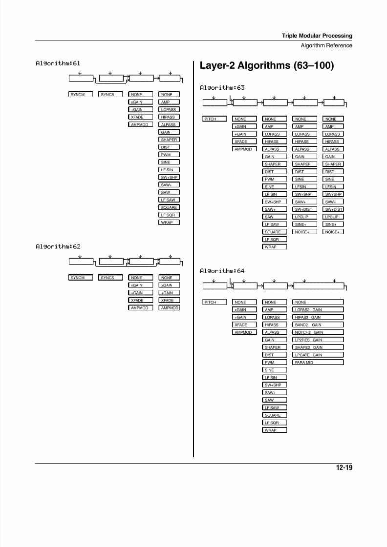
8/21/2019 MR_K2661
http://slidepdf.com/reader/full/mrk2661 359/499
Triple Modular Processing
Algorithm Reference
12-19
Algorithm:61
qwwerwwtqwwerwwt¥wwerwwtqwwerwtd jd u: gk jCVVVVVVM<>>>>>>S?VVVVVVBCVVVVVM
Algorithm:62
qwwerwwtqwwerwwt¥wwerwwt¥wwerwtd jd u: u: jCVVVVVVM<>>>>>>S¿>>>>>>S?VVVVVM
SYNCM SYNCS NONE NONE
xGAIN AMP
+GAIN LOPASS
XFADE HIPASS
AMPMOD ALPASS
GAIN
SHAPER
DIST
PWM
SINE
LF SIN
SW+SHP
SAW+
SAW
LF SAW
SQUARE
LF SQR
WRAP
SYNCM SYNCS NONE NONE
xGAIN xGAIN
+GAIN +GAIN
XFADE XFADE
AMPMOD AMPMOD
Layer-2 Algorithms (63–100)
Algorithm:63 qwwerwwt7wwerwwtqwwerwwtqwwerwwtqwwerwtd i; gk gk gk jCVVVVVVBCVVVVVVBCVVVVVVBCVVVVVVBCVVVVVM
Algorithm:64 6qwwerwwt7wwerwwtqwwerwwtqwwerwwwwwwerwt
d i; gk gk jCVVVVVVBCVVVVVVBCVVVVVVBCVVVVVVVVVVVVVM
PITCH NONE NONE NONE NONE
xGAIN AMP AMP AMP
+GAIN LOPASS LOPASS LOPASS
XFADE HIPASS HIPASS HIPASS
AMPMOD ALPASS ALPASS ALPASS
GAIN GAIN GAIN
SHAPER SHAPER SHAPER
DIST DIST DIST
PWM SINE SINE
SINE LFSIN LFSIN
LF SIN SW+SHP SW+SHP
SW+SHP SAW+ SAW+
SAW+ SW+DIST SW+DIST
SAW LPCLIP LPCLIP
LF SAW SINE+ SINE+
SQUARE NOISE+ NOISE+
LF SQR
WRAP
PITCH NONE NONE NONE
xGAIN AMP LOPAS2 GAIN
+GAIN LOPASS HIPAS2 GAIN
XFADE HIPASS BAND2 GAIN
AMPMOD ALPASS NOTCH2 GAIN
GAIN LP2RES GAIN
SHAPER SHAPE2 GAIN
DIST LPGATE GAIN
PWM PARA MID
SINE
LF SIN
SW+SHP
SAW+
SAW
LF SAW
SQUARE
LF SQR
WRAP
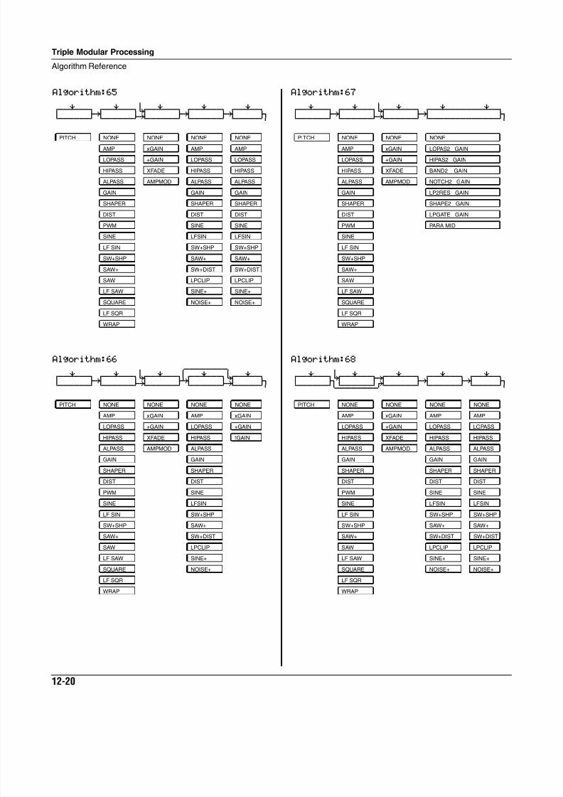
8/21/2019 MR_K2661
http://slidepdf.com/reader/full/mrk2661 360/499
12-20
Triple Modular Processing
Algorithm Reference
Algorithm:65 6qwwerwwtqwwerwwt7wwerwwtqwwerwwtqwwerwtd gk i; gk gk jCVVVVVVBCVVVVVVBNVVVVVVBCVVVVVVBCVVVVVM
Algorithm:66 6 5wwwwwwww6qwwerwwtqwwerwwt7wwerww†qwwerwwt7wwerwtd gk i; fk i; jCVVVVVVBCVVVVVVBNVVVVVVBCVVVVVVBNVVVVVM
PITCH NONE NONE NONE NONE
AMP xGAIN AMP AMP
LOPASS +GAIN LOPASS LOPASS
HIPASS XFADE HIPASS HIPASS
ALPASS AMPMOD ALPASS ALPASS
GAIN GAIN GAIN
SHAPER SHAPER SHAPER
DIST DIST DIST
PWM SINE SINE
SINE LFSIN LFSIN
LF SIN SW+SHP SW+SHP
SW+SHP SAW+ SAW+
SAW+ SW+DIST SW+DIST
SAW LPCLIP LPCLIP
LF SAW SINE+ SINE+
SQUARE NOISE+ NOISE+
LF SQR
WRAP
PITCH NONE NONE NONE NONE
AMP xGAIN AMP xGAIN
LOPASS +GAIN LOPASS +GAIN
HIPASS XFADE HIPASS !GAIN
ALPASS AMPMOD ALPASS
GAIN GAIN
SHAPER SHAPER
DIST DIST
PWM SINE
SINE LFSIN
LF SIN SW+SHP
SW+SHP SAW+
SAW+ SW+DIST
SAW LPCLIP
LF SAW SINE+
SQUARE NOISE+
LF SQR
WRAP
Algorithm:67 6qwwerwwtqwwerwwt7wwerwwtqwwerwwwwwwerwtd gk i; gk jCVVVVVVBCVVVVVVBNVVVVVVBCVVVVVVVVVVVVVM
Algorithm:68 6qwwerwwt7wwerwwt¥wwerwwtqwwerwwtqwwerwtd jU u: gk gk jCVVVVVVM<>>>>>>S?VVVVVVBCVVVVVVBCVVVVVM
PITCH NONE NONE NONE
AMP xGAIN LOPAS2 GAIN
LOPASS +GAIN HIPAS2 GAIN
HIPASS XFADE BAND2 GAIN
ALPASS AMPMOD NOTCH2 GAIN
GAIN LP2RES GAIN
SHAPER SHAPE2 GAIN
DIST LPGATE GAIN
PWM PARA MID
SINE
LF SIN
SW+SHP
SAW+
SAW
LF SAW
SQUARE
LF SQR
WRAP
PITCH NONE NONE NONE NONE
AMP xGAIN AMP AMP
LOPASS +GAIN LOPASS LOPASS
HIPASS XFADE HIPASS HIPASS
ALPASS AMPMOD ALPASS ALPASS
GAIN GAIN GAIN
SHAPER SHAPER SHAPER
DIST DIST DIST
PWM SINE SINE
SINE LFSIN LFSIN
LF SIN SW+SHP SW+SHP
SW+SHP SAW+ SAW+
SAW+ SW+DIST SW+DIST
SAW LPCLIP LPCLIP
LF SAW SINE+ SINE+
SQUARE NOISE+ NOISE+
LF SQR
WRAP
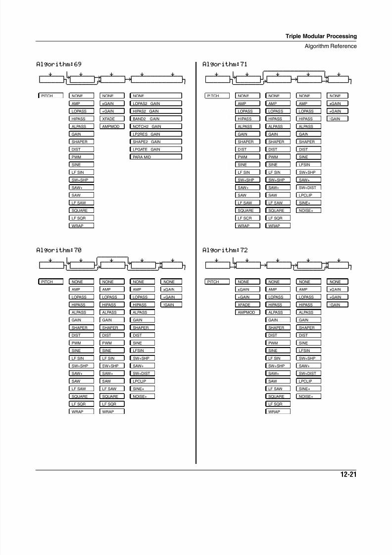
8/21/2019 MR_K2661
http://slidepdf.com/reader/full/mrk2661 361/499
Triple Modular Processing
Algorithm Reference
12-21
Algorithm:69 6qwwerwwt7wwerwwt¥wwerwwtqwwerwwwwwwerwtd jU u: gk jCVVVVVVM<>>>>>>S?VVVVVVBCVVVVVVVVVVVVVM
Algorithm:70 6 5wwwwwwww6qwwerwwt7wwerww†qwwerwwt7wwerwwt¥wwerwtd jU fO jU u: jCVVVVVVM<>>>>>>S?VVVVVVM<>>>>>>S?VVVVVM
PITCH NONE NONE NONE
AMP xGAIN LOPAS2 GAIN
LOPASS +GAIN HIPAS2 GAIN
HIPASS XFADE BAND2 GAIN
ALPASS AMPMOD NOTCH2 GAIN
GAIN LP2RES GAIN
SHAPER SHAPE2 GAIN
DIST LPGATE GAIN
PWM PARA MID
SINE
LF SIN
SW+SHP
SAW+
SAW
LF SAW
SQUARE
LF SQR
WRAP
PITCH NONE NONE NONE NONE
AMP AMP AMP xGAIN
LOPASS LOPASS LOPASS +GAIN
HIPASS HIPASS HIPASS !GAIN
ALPASS ALPASS ALPASS
GAIN GAIN GAIN
SHAPER SHAPER SHAPER
DIST DIST DIST
PWM PWM SINE
SINE SINE LFSIN
LF SIN LF SIN SW+SHP
SW+SHP SW+SHP SAW+
SAW+ SAW+ SW+DIST
SAW SAW LPCLIP
LF SAW LF SAW SINE+
SQUARE SQUARE NOISE+
LF SQR LF SQR
WRAP WRAP
Algorithm:71 6 5wwwwwwwwwwwwwwww6qwwerwwt7wwerww†qwwerwwtqwwerwwt7wwerwtd jU fO gk i; jCVVVVVVM<>>>>>>S?VVVVVVBCVVVVVVBNVVVVVM
Algorithm:72 6qwwerwwt7wwerwwtqwwerwwtqwwerwwt¥wwerwtd i; gk jk u: jCVVVVVVBNVVVVVVBCVVVVVVM<>>>>>>S?VVVVVM
PITCH NONE NONE NONE NONE
AMP AMP AMP xGAIN
LOPASS LOPASS LOPASS +GAIN
HIPASS HIPASS HIPASS !GAIN
ALPASS ALPASS ALPASS
GAIN GAIN GAIN
SHAPER SHAPER SHAPER
DIST DIST DIST
PWM PWM SINE
SINE SINE LFSIN
LF SIN LF SIN SW+SHP
SW+SHP SW+SHP SAW+
SAW+ SAW+ SW+DIST
SAW SAW LPCLIP
LF SAW LF SAW SINE+
SQUARE SQUARE NOISE+
LF SQR LF SQR
WRAP WRAP
PITCH NONE NONE NONE NONE
xGAIN AMP AMP xGAIN
+GAIN LOPASS LOPASS +GAIN
XFADE HIPASS HIPASS !GAIN
AMPMOD ALPASS ALPASS
GAIN GAIN
SHAPER SHAPER
DIST DIST
PWM SINE
SINE LFSIN
LF SIN SW+SHP
SW+SHP SAW+
SAW+ SW+DIST
SAW LPCLIP
LF SAW SINE+
SQUARE NOISE+
LF SQR
WRAP
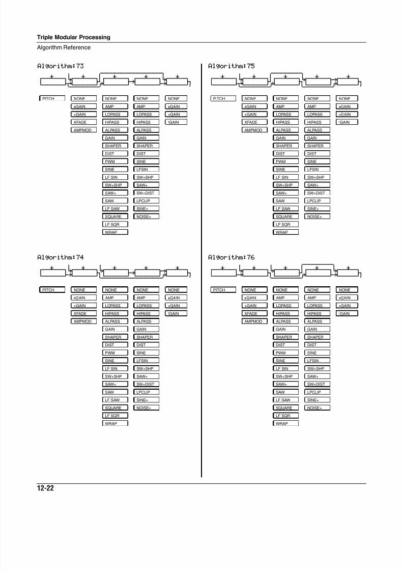
8/21/2019 MR_K2661
http://slidepdf.com/reader/full/mrk2661 362/499
12-22
Triple Modular Processing
Algorithm Reference
Algorithm:73 6 5wwwwwwwwwwwwwwww6qwwerwwt7wwerww†qwwerwwtqwwerwwt7wwerwtd J; fO gk i; jCVVVVVVM<>>>>>>S?VVVVVVBCVVVVVVBNVVVVVM
Algorithm:74 6 6qwwerwwt7wwerwwt7wwerwwtqwwerwwt¥wwerwtd i; jU gk u: jCVVVVVVBNVVVVVVM<>>>>>>S<>>>>>>S?VVVVVM
PITCH NONE NONE NONE NONE
xGAIN AMP AMP xGAIN
+GAIN LOPASS LOPASS +GAIN
XFADE HIPASS HIPASS !GAIN
AMPMOD ALPASS ALPASS
GAIN GAIN
SHAPER SHAPER
DIST DIST
PWM SINE
SINE LFSIN
LF SIN SW+SHP
SW+SHP SAW+
SAW+ SW+DIST
SAW LPCLIP
LF SAW SINE+
SQUARE NOISE+
LF SQR
WRAP
PITCH NONE NONE NONE NONE
xGAIN AMP AMP xGAIN
+GAIN LOPASS LOPASS +GAIN
XFADE HIPASS HIPASS !GAIN
AMPMOD ALPASS ALPASS
GAIN GAIN
SHAPER SHAPER
DIST DIST
PWM SINE
SINE LFSIN
LF SIN SW+SHP
SW+SHP SAW+
SAW+ SW+DIST
SAW LPCLIP
LF SAW SINE+
SQUARE NOISE+
LF SQR
WRAP
Algorithm:75 6 5wwwwwwww6qwwerwwt7wwerww†qwwerwwt7wwerwwt¥wwerwtd J; fO jU u: jCVVVVVVM<>>>>>>S?VVVVVVM<>>>>>>S?VVVVVM
Algorithm:76 6 6 5wwwwwwww6qwwerwwt7wwerwwt7wwerww†qwwerwwt7wwerwtd i; jU fO i; jCVVVVVVBNVVVVVVM<>>>>>>S?VVVVVVBNVVVVVM
PITCH NONE NONE NONE NONE
xGAIN AMP AMP xGAIN
+GAIN LOPASS LOPASS +GAIN
XFADE HIPASS HIPASS !GAIN
AMPMOD ALPASS ALPASS
GAIN GAIN
SHAPER SHAPER
DIST DIST
PWM SINE
SINE LFSIN
LF SIN SW+SHP
SW+SHP SAW+
SAW+ SW+DIST
SAW LPCLIP
LF SAW SINE+
SQUARE NOISE+
LF SQR
WRAP
PITCH NONE NONE NONE NONE
xGAIN AMP AMP xGAIN
+GAIN LOPASS LOPASS +GAIN
XFADE HIPASS HIPASS !GAIN
AMPMOD ALPASS ALPASS
GAIN GAIN
SHAPER SHAPER
DIST DIST
PWM SINE
SINE LFSIN
LF SIN SW+SHP
SW+SHP SAW+
SAW+ SW+DIST
SAW LPCLIP
LF SAW SINE+
SQUARE NOISE+
LF SQR
WRAP
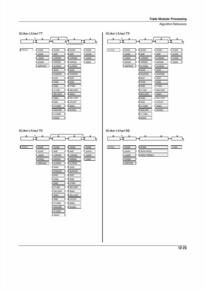
8/21/2019 MR_K2661
http://slidepdf.com/reader/full/mrk2661 363/499
Triple Modular Processing
Algorithm Reference
12-23
Algorithm:77 6 5wwwwwwww6qwwerwwt7wwerww†qwwerwwt7wwerwwt¥wwerwtd i; fk jU u: jCVVVVVVBNVVVVVVBCVVVVVVM<>>>>>>S?VVVVVM
Algorithm:78 6 5wwwwwwwwwwwwwwww6qwwerwwt7wwerww†qwwerwwtqwwerwwt7wwerwtd i; fk gk i; jCVVVVVVBNVVVVVVBCVVVVVVBCVVVVVVBNVVVVVM
PITCH NONE NONE NONE NONE
xGAIN AMP AMP xGAIN
+GAIN LOPASS LOPASS +GAIN
XFADE HIPASS HIPASS !GAIN
AMPMOD ALPASS ALPASS
GAIN GAIN
SHAPER SHAPER
DIST DIST
PWM SINE
SINE LFSIN
LF SIN SW+SHP
SW+SHP SAW+
SAW+ SW+DIST
SAW LPCLIP
LF SAW SINE+
SQUARE NOISE+
LF SQR
WRAP
PITCH NONE NONE NONE NONE
xGAIN AMP AMP xGAIN
+GAIN LOPASS LOPASS +GAIN
XFADE HIPASS HIPASS !GAIN
AMPMOD ALPASS ALPASS
GAIN GAIN
SHAPER SHAPER
DIST DIST
PWM SINE
SINE LFSIN
LF SIN SW+SHP
SW+SHP SAW+
SAW+ SW+DIST
SAW LPCLIP
LF SAW SINE+
SQUARE NOISE+
LF SQR
WRAP
Algorithm:79 6 5wwwwwwww6qwwerwwt7wwerwwtqwwerww†qwwerwwt7wwerwtd i; gk fk i; jCVVVVVVBNVVVVVVBCVVVVVVBCVVVVVVBNVVVVVM
Algorithm:80 6qwwerwwt7wwerwwtqwwerwwwwwwerwwtqwwerwtd i; gk gk jCVVVVVVBNVVVVVVBCVVVVVVVVVVVVVVBCVVVVVM
PITCH NONE NONE NONE NONE
xGAIN AMP AMP xGAIN
+GAIN LOPASS LOPASS +GAIN
XFADE HIPASS HIPASS !GAIN
AMPMOD ALPASS ALPASS
GAIN GAIN
SHAPER SHAPER
DIST DIST
PWM SINE
SINE LFSIN
LF SIN SW+SHP
SW+SHP SAW+
SAW+ SW+DIST
SAW LPCLIP
LF SAW SINE+
SQUARE NOISE+
LF SQR
WRAP
PITCH NONE NONE GAIN
xGAIN PARA BASS
+GAIN PARA TREBLE
XFADE
AMPMOD
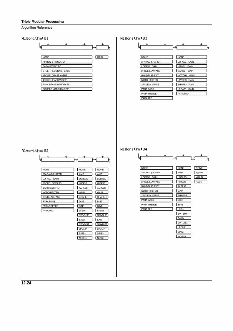
8/21/2019 MR_K2661
http://slidepdf.com/reader/full/mrk2661 364/499
12-24
Triple Modular Processing
Algorithm Reference
Algorithm:81 6
0wwerwwwwwwerwwwwwwerwwtqwwerwtK gk jCVVVVVVVVVVVVVVVVVVVVVVBCVVVVVM
Algorithm:82 6
0wwerwwwwwwerwwtqwwerwwtqwwerwtK gk gk jCVVVVVVVVVVVVVVBCVVVVVVBCVVVVVM
NONE GAIN
HIFREQ STIMULATOR
PARAMETRIC EQ
STEEP RESONANT BASS
4POLE LOPASS W/SEP
4POLE HIPASS W/SEP
TWIN PEAKS BANDPASS
DOUBLE NOTCH W/SEP
NONE NONE NONE
2PARAM SHAPER AMP AMP
LOPAS2 GAIN LOPASS LOPASS
2POLE LOWPASS HIPASS HIPASS
BANDPASS FILT ALPASS ALPASS
NOTCH FILTER GAIN GAIN
2POLE ALLPASS SHAPER SHAPER
PARA BASS DIST DIST
PARA TREBLE SINE SINE
PARA MID LFSIN LFSIN
SW+SHP SW+SHP
SAW+ SAW+
SW+DIST SW+DIST
LPCLIP LPCLIP
SINE+ SINE+
NOISE+ NOISE+
Algorithm:83 6
0wwerwwwwwwerwwtqwwerwwwwwwerwtK gk jCVVVVVVVVVVVVVVBCVVVVVVVVVVVVVB
Algorithm:84 6 6
0wwerwwwwwwerwwtqwwerwwt7wwerwtK gk i; jCVVVVVVVVVVVVVVBCVVVVVVBNVVVVVM
NONE NONE
2PARAM SHAPER LOPAS2 GAIN
LOPAS2 GAIN HIPAS2 GAIN
2POLE LOWPASS BAND2 GAIN
BANDPASS FILT NOTCH2 GAIN
NOTCH FILTER LP2RES GAIN
2POLE ALLPASS SHAPE2 GAIN
PARA BASS LPGATE GAIN
PARA TREBLE PARA MID
PARA MID
NONE NONE NONE
2PARAM SHAPER AMP xGAIN
LOPAS2 GAIN LOPASS +GAIN
2POLE LOWPASS HIPASS !GAIN
BANDPASS FILT ALPASS
NOTCH FILTER GAIN
2POLE ALLPASS SHAPER
PARA BASS DIST
PARA TREBLE SINE
PARA MID LFSIN
SW+SHP
SAW+
SW+DIST
LPCLIP
SINE+
NOISE+
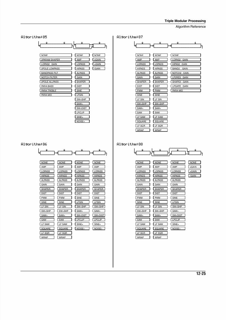
8/21/2019 MR_K2661
http://slidepdf.com/reader/full/mrk2661 365/499
Triple Modular Processing
Algorithm Reference
12-25
Algorithm:85 6 6
0wwerwwwwwwerwwt7wwerwwt¥wwerwtK jU u: jCVVVVVVVVVVVVVVM<>>>>>>S?VVVVVM
Algorithm:86 6
0wwerwwtqwwerwwtqwwerwwtqwwerwtK gk gk gk jCVVVVVVBCVVVVVVBCVVVVVVBCVVVVVM
NONE NONE NONE
2PARAM SHAPER AMP xGAIN
LOPAS2 GAIN LOPASS +GAIN
2POLE LOWPASS HIPASS !GAIN
BANDPASS FILT ALPASS
NOTCH FILTER GAIN
2POLE ALLPASS SHAPER
PARA BASS DIST
PARA TREBLE SINE
PARA MID LFSIN
SW+SHP
SAW+
SW+DIST
LPCLIP
SINE+
NOISE+
NONE NONE NONE NONE
AMP AMP AMP AMP
LOPASS LOPASS LOPASS LOPASS
HIPASS HIPASS HIPASS HIPASS
ALPASS ALPASS ALPASS ALPASS
GAIN GAIN GAIN GAIN
SHAPER SHAPER SHAPER SHAPER
DIST DIST DIST DIST
PWM PWM SINE SINE
SINE SINE LFSIN LFSIN
LF SIN LF SIN SW+SHP SW+SHP
SW+SHP SW+SHP SAW+ SAW+
SAW+ SAW+ SW+DIST SW+DIST
SAW SAW LPCLIP LPCLIP
LF SAW LF SAW SINE+ SINE+
SQUARE SQUARE NOISE+ NOISE+
LF SQR LF SQR
WRAP WRAP
Algorithm:87 6
0wwerwwtqwwerwwtqwwerwwwwwwewwtK gk gk jCVVVVVVBCVVVVVVBCVVVVVVVVVVVVVM
Algorithm:88 6 6 5wwwwwwww6
0wwerwwt7wwerww†qwwerwwt7wwerwtK jU fO i; jCVVVVVVM<>>>>>>S?VVVVVVBNVVVVVM
NONE NONE NONE
AMP AMP LOPAS2 GAIN
LOPASS LOPASS HIPAS2 GAIN
HIPASS HIPASS BAND2 GAIN
ALPASS ALPASS NOTCH2 GAIN
GAIN GAIN LP2RES GAIN
SHAPER SHAPER SHAPE2 GAIN
DIST DIST LPGATE GAIN
PWM PWM PARA MID
SINE SINE
LF SIN LF SIN
SW+SHP SW+SHP
SAW+ SAW+
SAW SAW
LF SAW LF SAW
SQUARE SQUARE
LF SQR LF SQR
WRAP WRAP
NONE NONE NONE NONE
AMP AMP AMP xGAIN
LOPASS LOPASS LOPASS +GAIN
HIPASS HIPASS HIPASS !GAIN
ALPASS ALPASS ALPASS
GAIN GAIN GAIN
SHAPER SHAPER SHAPER
DIST DIST DIST
PWM PWM SINE
SINE SINE LFSIN
LF SIN LF SIN SW+SHP
SW+SHP SW+SHP SAW+
SAW+ SAW+ SW+DIST
SAW SAW LPCLIP
LF SAW LF SAW SINE+
SQUARE SQUARE NOISE+
LF SQR LF SQR
WRAP WRAP
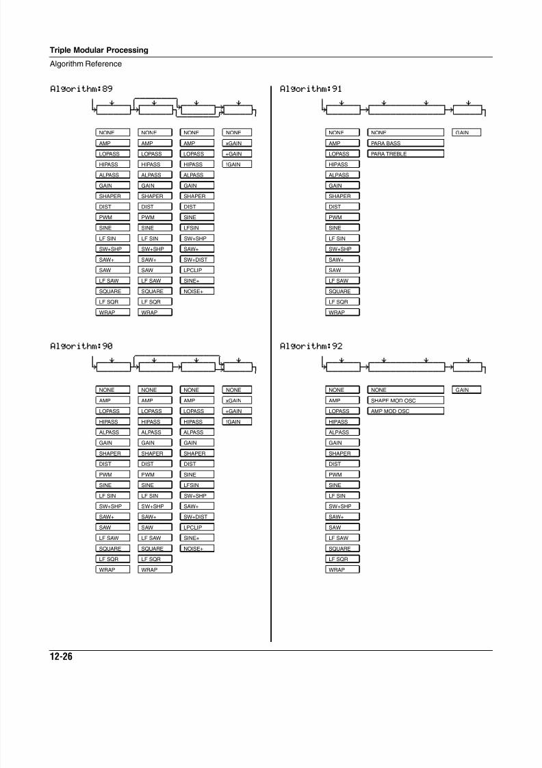
8/21/2019 MR_K2661
http://slidepdf.com/reader/full/mrk2661 366/499
12-26
Triple Modular Processing
Algorithm Reference
Algorithm:89 6 5wwwwwwww6
0wwerww†qwwerwwt7wwerwwt¥wwerwtK fk jU u: jCVVVVVVBCVVVVVVM<>>>>>>S?VVVVVM
Algorithm:90 6 5wwwwwwwwwwwwwwww6
0wwerww†qwwerwwtqwwerwwt7wwerwtK fk gk i; jCVVVVVVBCVVVVVVBCVVVVVVBNVVVVVM
NONE NONE NONE NONE
AMP AMP AMP xGAIN
LOPASS LOPASS LOPASS +GAIN
HIPASS HIPASS HIPASS !GAIN
ALPASS ALPASS ALPASS
GAIN GAIN GAIN
SHAPER SHAPER SHAPER
DIST DIST DIST
PWM PWM SINE
SINE SINE LFSIN
LF SIN LF SIN SW+SHP
SW+SHP SW+SHP SAW+
SAW+ SAW+ SW+DIST
SAW SAW LPCLIP
LF SAW LF SAW SINE+
SQUARE SQUARE NOISE+
LF SQR LF SQR
WRAP WRAP
Algorithm:91 6
0wwerwwtqwwerwwwwwwerwwtqwwerwtK gk gk jCVVVVVVBCVVVVVVVVVVVVVVBCVVVVVM
Algorithm:92 6
0wwerwwtqwwerwwwwwwerwwtqwwerwtK gk gk jCVVVVVVBCVVVVVVVVVVVVVVBCVVVVVM
NONE NONE GAIN
AMP PARA BASS
LOPASS PARA TREBLE
HIPASS
ALPASS
GAIN
SHAPER
DIST
PWM
SINE
LF SIN
SW+SHP
SAW+
SAW
LF SAW
SQUARE
LF SQR
WRAP
NONE NONE GAIN
AMP SHAPE MOD OSC
LOPASS AMP MOD OSC
HIPASS
ALPASS
GAIN
SHAPER
DIST
PWM
SINE
LF SIN
SW+SHP
SAW+
SAW
LF SAW
SQUARE
LF SQR
WRAP
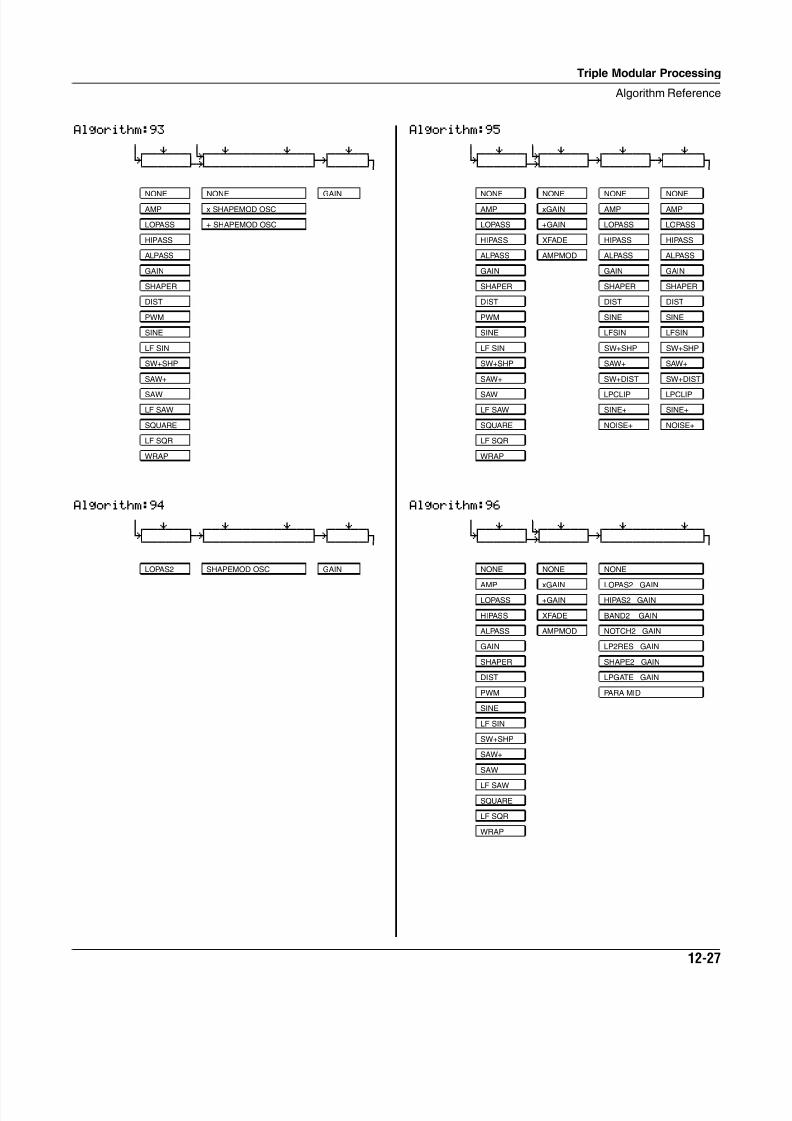
8/21/2019 MR_K2661
http://slidepdf.com/reader/full/mrk2661 367/499
Triple Modular Processing
Algorithm Reference
12-27
Algorithm:93 6 6
0wwerwwt7wwerwwwwwwerwwtqwwerwtK i; gk jCVVVVVVBNVVVVVVVVVVVVVVBCVVVVVM
Algorithm:94 6
0wwerwwtqwwerwwwwwwerwwtqwwerwtK gk gk jCVVVVVVBCVVVVVVVVVVVVVVBCVVVVVM
NONE NONE GAIN
AMP x SHAPEMOD OSC
LOPASS + SHAPEMOD OSC
HIPASS
ALPASS
GAIN
SHAPER
DIST
PWM
SINE
LF SIN
SW+SHP
SAW+
SAW
LF SAW
SQUARE
LF SQR
WRAP
LOPAS2 SHAPEMOD OSC GAIN
Algorithm:95 6 6
0wwerwwt7wwerwwtqwwerwwtqwwerwtK i; gk gk jCVVVVVVBNVVVVVVBCVVVVVVBCVVVVVM
Algorithm:96 6 6
0wwerwwt7wwerwwtqwwerwwwwwwerwtK i; gk jCVVVVVVBNVVVVVVBCVVVVVVVVVVVVVM
NONE NONE NONE NONE
AMP xGAIN AMP AMP
LOPASS +GAIN LOPASS LOPASS
HIPASS XFADE HIPASS HIPASS
ALPASS AMPMOD ALPASS ALPASS
GAIN GAIN GAIN
SHAPER SHAPER SHAPER
DIST DIST DIST
PWM SINE SINE
SINE LFSIN LFSIN
LF SIN SW+SHP SW+SHP
SW+SHP SAW+ SAW+
SAW+ SW+DIST SW+DIST
SAW LPCLIP LPCLIP
LF SAW SINE+ SINE+
SQUARE NOISE+ NOISE+
LF SQR
WRAP
NONE NONE NONE
AMP xGAIN LOPAS2 GAIN
LOPASS +GAIN HIPAS2 GAIN
HIPASS XFADE BAND2 GAIN
ALPASS AMPMOD NOTCH2 GAIN
GAIN LP2RES GAIN
SHAPER SHAPE2 GAIN
DIST LPGATE GAIN
PWM PARA MID
SINE
LF SIN
SW+SHP
SAW+
SAW
LF SAW
SQUARE
LF SQR
WRAP
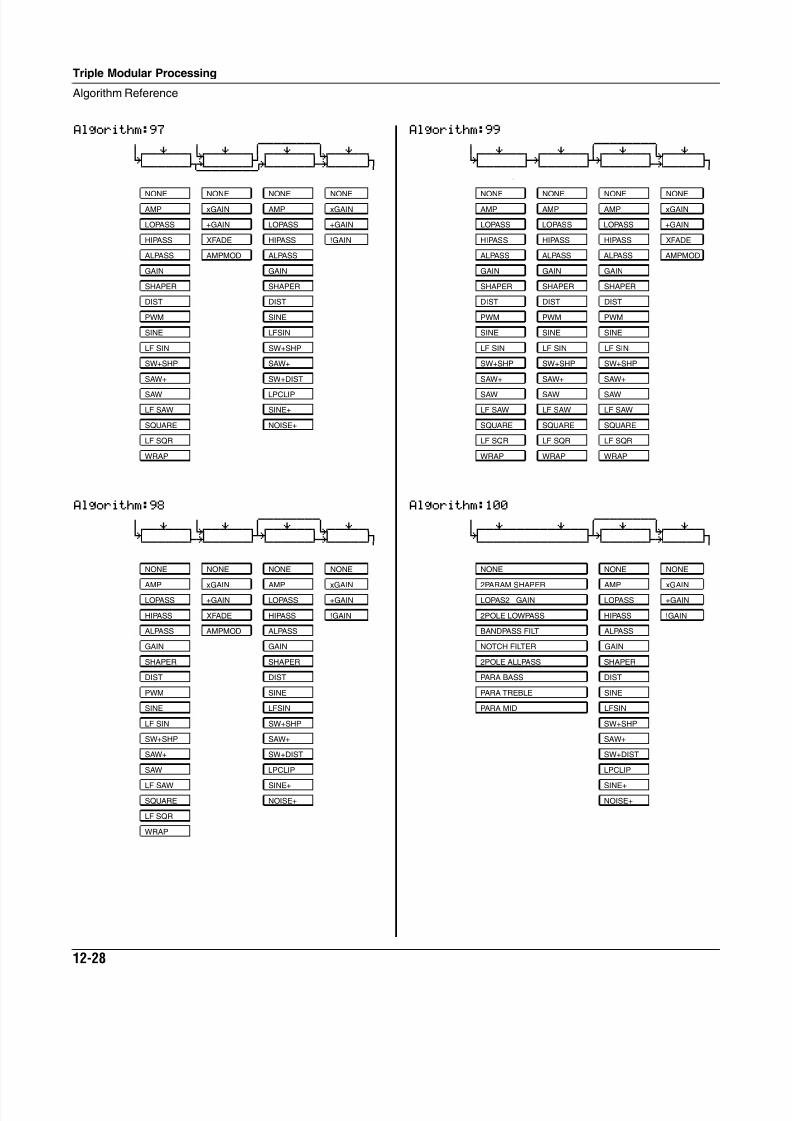
8/21/2019 MR_K2661
http://slidepdf.com/reader/full/mrk2661 368/499
12-28
Triple Modular Processing
Algorithm Reference
Algorithm:97 6 6 5wwwwwwww6
0wwerwwt7wwerww†qwwerwwt7wwerwtK J; fO i; jCVVVVVVM<>>>>>>S?VVVVVVBNVVVVVM
Algorithm:98 6 6 5wwwwwwww6
0wwerwwt7wwerww†qwwerwwt7wwerwtK i; fk i; jCVVVVVVBNVVVVVVBCVVVVVVBNVVVVVM
NONE NONE NONE NONE
AMP xGAIN AMP xGAIN
LOPASS +GAIN LOPASS +GAIN
HIPASS XFADE HIPASS !GAIN
ALPASS AMPMOD ALPASS
GAIN GAIN
SHAPER SHAPER
DIST DIST
PWM SINE
SINE LFSIN
LF SIN SW+SHP
SW+SHP SAW+
SAW+ SW+DIST
SAW LPCLIP
LF SAW SINE+
SQUARE NOISE+
LF SQR
WRAP
NONE NONE NONE NONE
AMP xGAIN AMP xGAIN
LOPASS +GAIN LOPASS +GAIN
HIPASS XFADE HIPASS !GAIN
ALPASS AMPMOD ALPASS
GAIN GAIN
SHAPER SHAPER
DIST DIST
PWM SINE
SINE LFSIN
LF SIN SW+SHP
SW+SHP SAW+
SAW+ SW+DIST
SAW LPCLIP
LF SAW SINE+
SQUARE NOISE+
LF SQR
WRAP
Algorithm:99 6 5wwwwwwww6
0wwerwwtqwwerww†qwwerwwt7wwerwtK gk fk i; jCVVVVVVBCVVVVVVBCVVVVVVBNVVVVVM
\
Algorithm:100 6 5wwwwwwww6
0wwerwwwwwwerww†qwwerwwt7wwerwtK fk i; jCVVVVVVVVVVVVVVBCVVVVVVBNVVVVVM
NONE NONE NONE NONE
AMP AMP AMP xGAIN
LOPASS LOPASS LOPASS +GAIN
HIPASS HIPASS HIPASS XFADE
ALPASS ALPASS ALPASS AMPMOD
GAIN GAIN GAIN
SHAPER SHAPER SHAPER
DIST DIST DIST
PWM PWM PWM
SINE SINE SINE
LF SIN LF SIN LF SIN
SW+SHP SW+SHP SW+SHP
SAW+ SAW+ SAW+
SAW SAW SAW
LF SAW LF SAW LF SAW
SQUARE SQUARE SQUARE
LF SQR LF SQR LF SQR
WRAP WRAP WRAP
NONE NONE NONE
2PARAM SHAPER AMP xGAIN
LOPAS2 GAIN LOPASS +GAIN
2POLE LOWPASS HIPASS !GAIN
BANDPASS FILT ALPASS
NOTCH FILTER GAIN
2POLE ALLPASS SHAPER
PARA BASS DIST
PARA TREBLE SINE
PARA MID LFSIN
SW+SHP
SAW+
SW+DIST
LPCLIP
SINE+
NOISE+
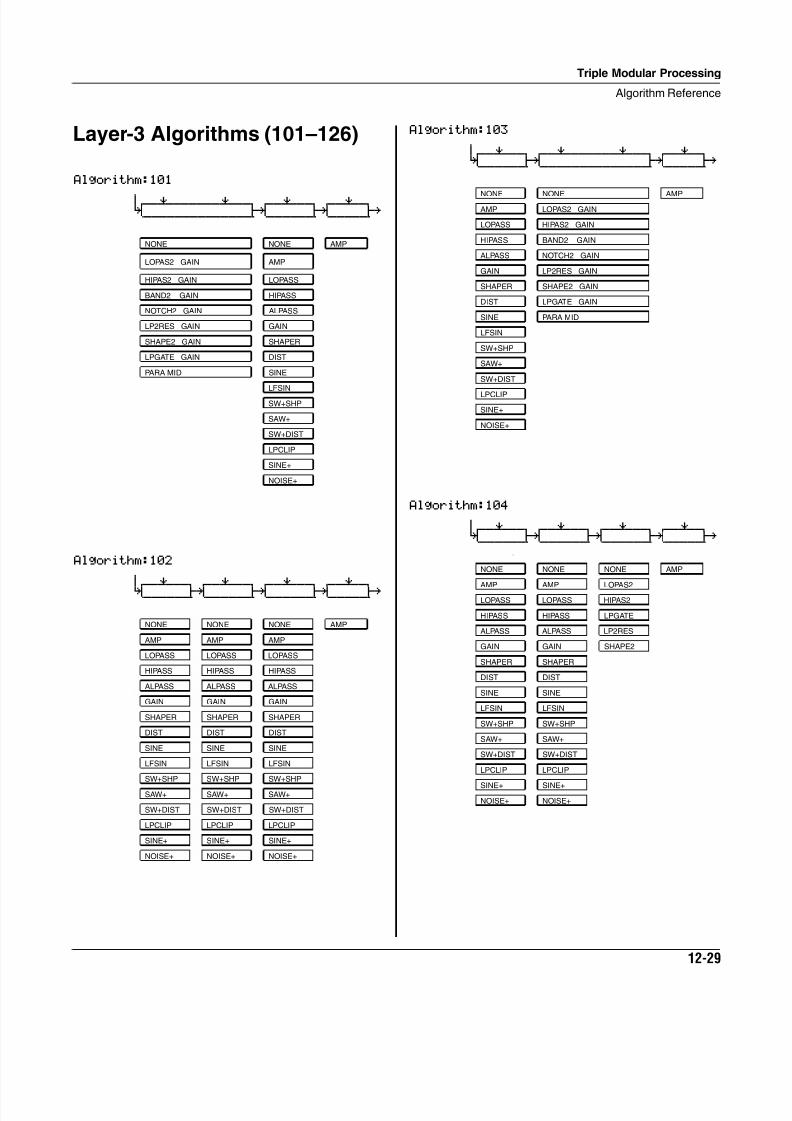
8/21/2019 MR_K2661
http://slidepdf.com/reader/full/mrk2661 369/499
Triple Modular Processing
Algorithm Reference
12-29
Layer-3 Algorithms (101–126)
Algorithm:101 6
0wwerwwwwwwerwwtqwwerwwtqwwerwtK gk gk gh
CVVVVVVVVVVVVVVBCVVVVVVBCVVVVVB
Algorithm:102 6
0wwerwwtqwwerwwtqwwerwwtqwwerwt
K gk gk gk gh CVVVVVVBCVVVVVVBCVVVVVVBCVVVVVB
NONE NONE AMP
LOPAS2 GAIN AMP
HIPAS2 GAIN LOPASS
BAND2 GAIN HIPASS
NOTCH2 GAIN ALPASS
LP2RES GAIN GAIN
SHAPE2 GAIN SHAPER
LPGATE GAIN DIST
PARA MID SINE
LFSIN
SW+SHP
SAW+
SW+DIST
LPCLIP
SINE+
NOISE+
NONE NONE NONE AMP
AMP AMP AMP
LOPASS LOPASS LOPASS
HIPASS HIPASS HIPASS
ALPASS ALPASS ALPASS
GAIN GAIN GAIN
SHAPER SHAPER SHAPER
DIST DIST DIST
SINE SINE SINE
LFSIN LFSIN LFSIN
SW+SHP SW+SHP SW+SHP
SAW+ SAW+ SAW+
SW+DIST SW+DIST SW+DIST
LPCLIP LPCLIP LPCLIP
SINE+ SINE+ SINE+
NOISE+ NOISE+ NOISE+
Algorithm:103 6
0wwerwwtqwwerwwwwwwerwwtqwwerwtK gk gk gh
CVVVVVVBCVVVVVVVVVVVVVVBCVVVVVB
Algorithm:104 6
0wwerwwtqwwerwwtqwwerwwtqwwerwtK gk gk gk gh
CVVVVVVBCVVVVVVBCVVVVVVBCVVVVVB \
NONE NONE AMP
AMP LOPAS2 GAIN
LOPASS HIPAS2 GAIN
HIPASS BAND2 GAIN
ALPASS NOTCH2 GAIN
GAIN LP2RES GAIN
SHAPER SHAPE2 GAIN
DIST LPGATE GAIN
SINE PARA MID
LFSIN
SW+SHP
SAW+
SW+DIST
LPCLIP
SINE+
NOISE+
NONE NONE NONE AMP
AMP AMP LOPAS2
LOPASS LOPASS HIPAS2
HIPASS HIPASS LPGATE
ALPASS ALPASS LP2RES
GAIN GAIN SHAPE2
SHAPER SHAPER
DIST DIST
SINE SINE
LFSIN LFSIN
SW+SHP SW+SHP
SAW+ SAW+
SW+DIST SW+DIST
LPCLIP LPCLIP
SINE+ SINE+
NOISE+ NOISE+
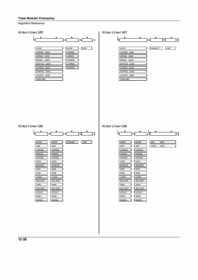
8/21/2019 MR_K2661
http://slidepdf.com/reader/full/mrk2661 370/499
12-30
Triple Modular Processing
Algorithm Reference
Algorithm:105 6
0wwerwwwwwwerwwtqwwerwwtqwwerwtK gk gk gh
CVVVVVVVVVVVVVVBCVVVVVVBCVVVVVB
Algorithm:106 6
0wwerwwtqwwerwwtqwwerwwt¥wwerwty K gk gk G; GH CVVVVVVBCVVVVVVBCVVVVVVBNVVVVVBP
NONE NONE AMP
LOPAS2 GAIN LOPAS2
HIPAS2 GAIN HIPAS2
BAND2 GAIN LPGATE
NOTCH2 GAIN LP2RES
LP2RES GAIN SHAPE2
SHAPE2 GAIN
LPGATE GAIN
PARA MID
NONE NONE PANNER AMP
AMP AMP
LOPASS LOPASS
HIPASS HIPASS
ALPASS ALPASS
GAIN GAIN
SHAPER SHAPER
DIST DIST
SINE SINE
LFSIN LFSIN
SW+SHP SW+SHP
SAW+ SAW+
SW+DIST SW+DIST
LPCLIP LPCLIP
SINE+ SINE+
NOISE+ NOISE+
Algorithm:107 6
0wwerwwwwwwerwwtqwwerwwt¥wwerwty K gk G; GH CVVVVVVVVVVVVVVBCVVVVVVBNVVVVVBP
Algorithm:108 6 6
0wwerwwtqwwerwwt7wwerwwwwwwerwty K gk i; GH CVVVVVVBCVVVVVVBCVVVVVVVVVVVVVBP
NONE PANNER AMP
LOPAS2 GAIN
HIPAS2 GAIN
BAND2 GAIN
NOTCH2 GAIN
LP2RES GAIN
SHAPE2 GAIN
LPGATE GAIN
PARA MID
NONE NONE BAL AMP
AMP AMP AMPU AMPL
LOPASS LOPASS
HIPASS HIPASS
ALPASS ALPASS
GAIN GAIN
SHAPER SHAPER
DIST DIST
SINE SINE
LFSIN LFSIN
SW+SHP SW+SHP
SAW+ SAW+
SW+DIST SW+DIST
LPCLIP LPCLIP
SINE+ SINE+
NOISE+ NOISE+
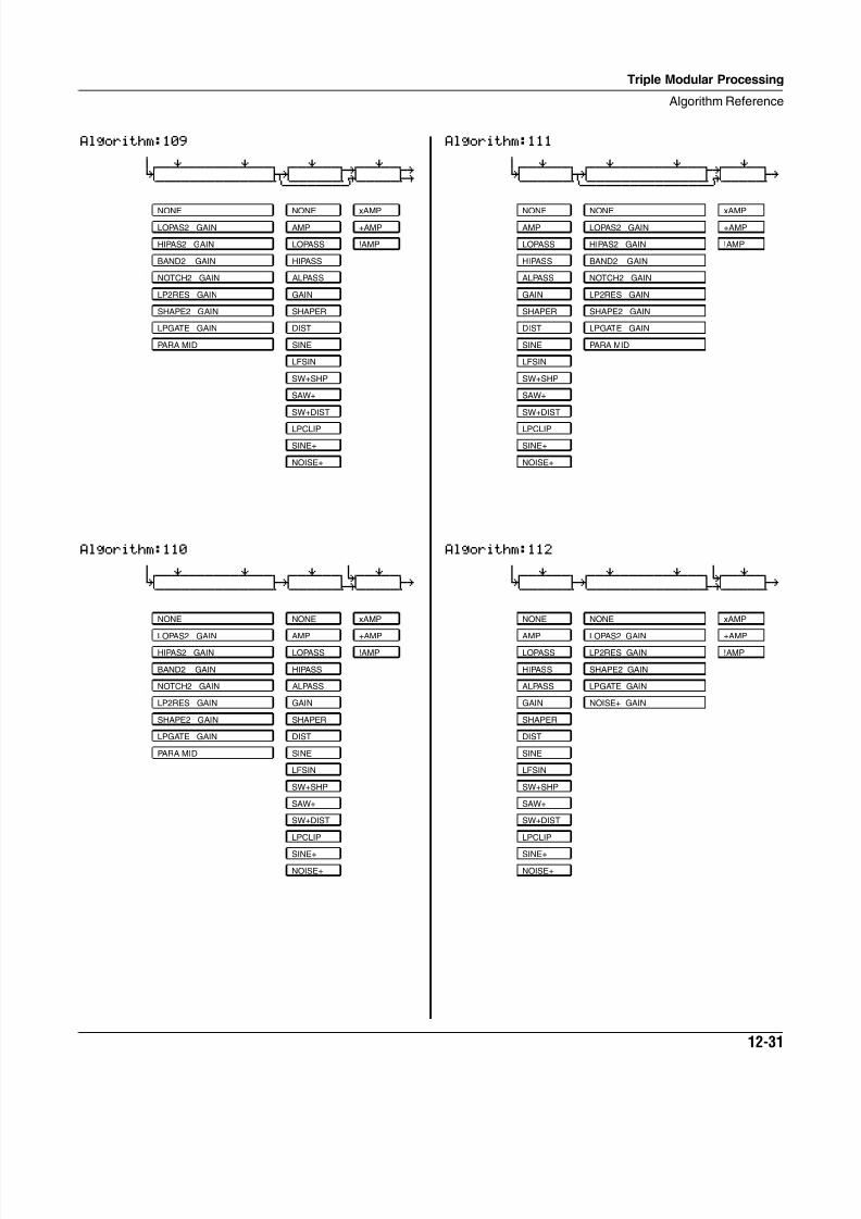
8/21/2019 MR_K2661
http://slidepdf.com/reader/full/mrk2661 371/499
Triple Modular Processing
Algorithm Reference
12-31
Algorithm:109 6
0wwerwwwwwwerwwtqwwerwwt¥wwerwty K jk u: GH CVVVVVVVVVVVVVVM<>>>>>>S?VVVVVBP
Algorithm:110 6 6
0wwerwwwwwwerwwtqwwerwwt7wwerwtK gk i; gh
CVVVVVVVVVVVVVVBCVVVVVVBNVVVVVB
NONE NONE xAMP
LOPAS2 GAIN AMP +AMP
HIPAS2 GAIN LOPASS !AMP
BAND2 GAIN HIPASS
NOTCH2 GAIN ALPASS
LP2RES GAIN GAIN
SHAPE2 GAIN SHAPER
LPGATE GAIN DIST
PARA MID SINE
LFSIN
SW+SHP
SAW+
SW+DIST
LPCLIP
SINE+
NOISE+
NONE NONE xAMP
LOPAS2 GAIN AMP +AMP
HIPAS2 GAIN LOPASS !AMP
BAND2 GAIN HIPASS
NOTCH2 GAIN ALPASS
LP2RES GAIN GAIN
SHAPE2 GAIN SHAPER
LPGATE GAIN DIST
PARA MID SINE
LFSIN
SW+SHP
SAW+
SW+DIST
LPCLIP
SINE+
NOISE+
Algorithm:111 6
0wwerwwtqwwerwwwwwwerwwt¥wwerwtK jk u: gh
CVVVVVVM<>>>>>>>>>>>>>>S?VVVVVB
Algorithm:112 6 6
0wwerwwtqwwerwwwwwwerwwt7wwerwtK gk i; gh
CVVVVVVBCVVVVVVVVVVVVVVBNVVVVVB
NONE NONE xAMP
AMP LOPAS2 GAIN +AMP
LOPASS HIPAS2 GAIN !AMP
HIPASS BAND2 GAIN
ALPASS NOTCH2 GAIN
GAIN LP2RES GAIN
SHAPER SHAPE2 GAIN
DIST LPGATE GAIN
SINE PARA MID
LFSIN
SW+SHP
SAW+
SW+DIST
LPCLIP
SINE+
NOISE+
NONE NONE xAMP
AMP LOPAS2 GAIN +AMP
LOPASS LP2RES GAIN !AMP
HIPASS SHAPE2 GAIN
ALPASS LPGATE GAIN
GAIN NOISE+ GAIN
SHAPER
DIST
SINE
LFSIN
SW+SHP
SAW+
SW+DIST
LPCLIP
SINE+
NOISE+
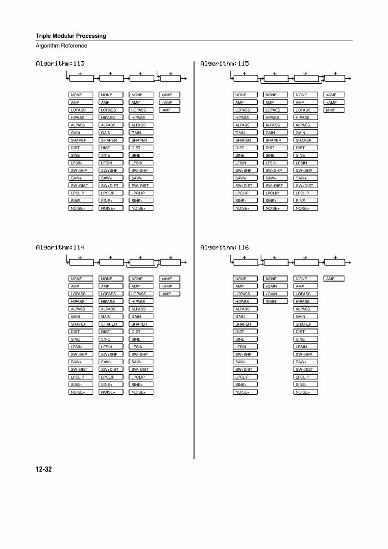
8/21/2019 MR_K2661
http://slidepdf.com/reader/full/mrk2661 372/499
12-32
Triple Modular Processing
Algorithm Reference
Algorithm:113 6 6
0wwerwwtqwwerwwtqwwerwwt7wwerwtK gk gk i; gh
CVVVVVVBCVVVVVVBCVVVVVVBNVVVVVB
Algorithm:114 6
0wwerwwtqwwerwwtqwwerwwt¥wwerwtK gk jk u: gh
CVVVVVVBCVVVVVVM<>>>>>>S?VVVVVB
NONE NONE NONE xAMP
AMP AMP AMP +AMP
LOPASS LOPASS LOPASS !AMP
HIPASS HIPASS HIPASS
ALPASS ALPASS ALPASS
GAIN GAIN GAIN
SHAPER SHAPER SHAPER
DIST DIST DIST
SINE SINE SINE
LFSIN LFSIN LFSIN
SW+SHP SW+SHP SW+SHP
SAW+ SAW+ SAW+
SW+DIST SW+DIST SW+DIST
LPCLIP LPCLIP LPCLIP
SINE+ SINE+ SINE+
NOISE+ NOISE+ NOISE+
Algorithm:115 6
0wwerwwtqwwerwwtqwwerwwt¥wwerwtK jk gk u: gh
CVVVVVVM<>>>>>>S<>>>>>>S?VVVVVB
Algorithm:116 6 6
0wwerwwt7wwerwwtqwwerwwtqwwerwtK i; gk gk gh
CVVVVVVBNVVVVVVBCVVVVVVBCVVVVVB
NONE NONE NONE xAMP
AMP AMP AMP +AMP
LOPASS LOPASS LOPASS !AMP
HIPASS HIPASS HIPASS
ALPASS ALPASS ALPASS
GAIN GAIN GAIN
SHAPER SHAPER SHAPER
DIST DIST DIST
SINE SINE SINE
LFSIN LFSIN LFSIN
SW+SHP SW+SHP SW+SHP
SAW+ SAW+ SAW+
SW+DIST SW+DIST SW+DIST
LPCLIP LPCLIP LPCLIP
SINE+ SINE+ SINE+
NOISE+ NOISE+ NOISE+
NONE NONE NONE AMP
AMP xGAIN AMP
LOPASS +GAIN LOPASS
HIPASS !GAIN HIPASS
ALPASS ALPASS
GAIN GAIN
SHAPER SHAPER
DIST DIST
SINE SINE
LFSIN LFSIN
SW+SHP SW+SHP
SAW+ SAW+
SW+DIST SW+DIST
LPCLIP LPCLIP
SINE+ SINE+
NOISE+ NOISE+
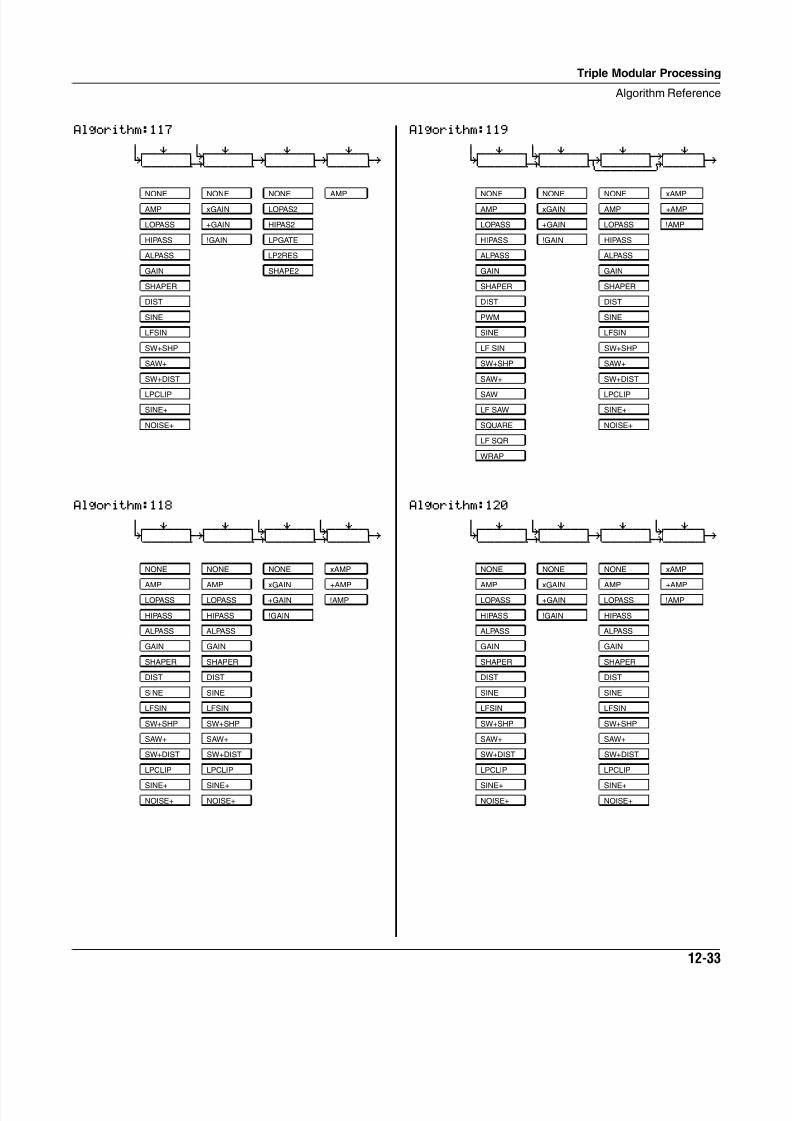
8/21/2019 MR_K2661
http://slidepdf.com/reader/full/mrk2661 373/499
Triple Modular Processing
Algorithm Reference
12-33
Algorithm:117 6 6
0wwerwwt7wwerwwtqwwerwwtqwwerwtK i; gk gk gh
CVVVVVVBNVVVVVVBCVVVVVVBCVVVVVB
Algorithm:118 6 6 6
0wwerwwtqwwerwwt7wwerwwt7wwerwtK gk i; i; gh
CVVVVVVBCVVVVVVBNVVVVVVBNVVVVVB
NONE NONE NONE AMP
AMP xGAIN LOPAS2
LOPASS +GAIN HIPAS2
HIPASS !GAIN LPGATE
ALPASS LP2RES
GAIN SHAPE2
SHAPER
DIST
SINE
LFSIN
SW+SHP
SAW+
SW+DIST
LPCLIP
SINE+
NOISE+
NONE NONE NONE xAMP
AMP AMP xGAIN +AMP
LOPASS LOPASS +GAIN !AMP
HIPASS HIPASS !GAIN
ALPASS ALPASS
GAIN GAIN
SHAPER SHAPER
DIST DIST
SINE SINE
LFSIN LFSIN
SW+SHP SW+SHP
SAW+ SAW+
SW+DIST SW+DIST
LPCLIP LPCLIP
SINE+ SINE+
NOISE+ NOISE+
Algorithm:119 6 6
0wwerwwt7wwerwwtqwwerwwt¥wwerwtK i; jk u: gh
CVVVVVVBNVVVVVVM<>>>>>>S?VVVVVB
Algorithm:120 6 6 6
0wwerwwt7wwerwwtqwwerwwt7wwerwtK i; gk i; gh
CVVVVVVBNVVVVVVBCVVVVVVBNVVVVVB
NONE NONE NONE xAMP
AMP xGAIN AMP +AMP
LOPASS +GAIN LOPASS !AMP
HIPASS !GAIN HIPASS
ALPASS ALPASS
GAIN GAIN
SHAPER SHAPER
DIST DIST
PWM SINE
SINE LFSIN
LF SIN SW+SHP
SW+SHP SAW+
SAW+ SW+DIST
SAW LPCLIP
LF SAW SINE+
SQUARE NOISE+
LF SQR
WRAP
NONE NONE NONE xAMP
AMP xGAIN AMP +AMP
LOPASS +GAIN LOPASS !AMP
HIPASS !GAIN HIPASS
ALPASS ALPASS
GAIN GAIN
SHAPER SHAPER
DIST DIST
SINE SINE
LFSIN LFSIN
SW+SHP SW+SHP
SAW+ SAW+
SW+DIST SW+DIST
LPCLIP LPCLIP
SINE+ SINE+
NOISE+ NOISE+
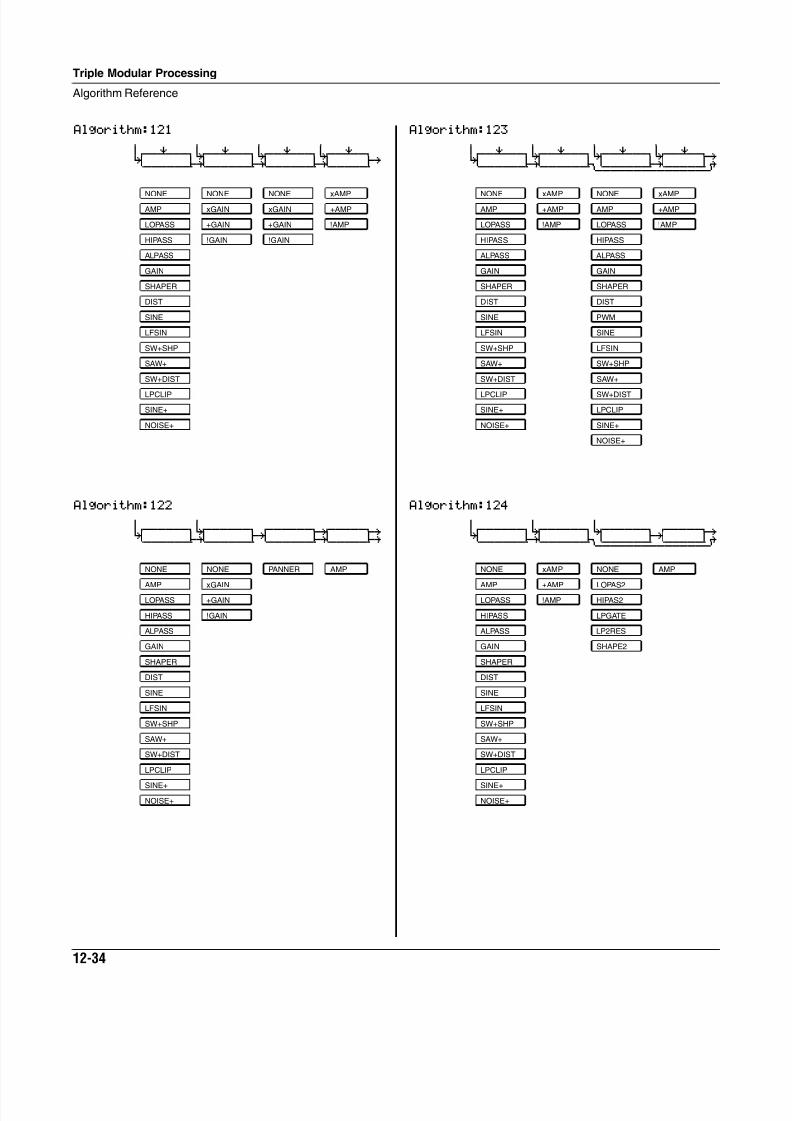
8/21/2019 MR_K2661
http://slidepdf.com/reader/full/mrk2661 374/499
12-34
Triple Modular Processing
Algorithm Reference
Algorithm:121 6 6 6 6
0wwerwwt7wwerwwt7wwerwwt7wwerwtK i; i; i; gh
CVVVVVVBNVVVVVVBNVVVVVVBNVVVVVB
Algorithm:122 6 6
0wwwwwwt7wwwwwwtqwwwwwwt¥wwwwwty K i; gk G; GH CVVVVVVBNVVVVVVBCVVVVVVBNVVVVVBP
NONE NONE NONE xAMP
AMP xGAIN xGAIN +AMP
LOPASS +GAIN +GAIN !AMP
HIPASS !GAIN !GAIN
ALPASS
GAIN
SHAPER
DIST
SINE
LFSIN
SW+SHP
SAW+
SW+DIST
LPCLIP
SINE+
NOISE+
NONE NONE PANNER AMP
AMP xGAIN
LOPASS +GAIN
HIPASS !GAIN
ALPASS
GAIN
SHAPER
DIST
SINE
LFSIN
SW+SHP
SAW+
SW+DIST
LPCLIP
SINE+
NOISE+
Algorithm:123 6 6 6 6
0wwerwwt7wwerwwt7wwerwwt7wwerwty K i; JU i; uÓ CVVVVVVBNVVVVVVM<>>>>>>SL>>>>>S»
Algorithm:124 6 6 6
0wwwwwwt7wwwwwwt7wwwwwwtqwwwwwty K i; JU gk uÓ CVVVVVVBNVVVVVVM<>>>>>>S<>>>>>S»
NONE xAMP NONE xAMP
AMP +AMP AMP +AMP
LOPASS !AMP LOPASS !AMP
HIPASS HIPASS
ALPASS ALPASS
GAIN GAIN
SHAPER SHAPER
DIST DIST
SINE PWM
LFSIN SINE
SW+SHP LFSIN
SAW+ SW+SHP
SW+DIST SAW+
LPCLIP SW+DIST
SINE+ LPCLIP
NOISE+ SINE+
NOISE+
NONE xAMP NONE AMP
AMP +AMP LOPAS2
LOPASS !AMP HIPAS2
HIPASS LPGATE
ALPASS LP2RES
GAIN SHAPE2
SHAPER
DIST
SINE
LFSIN
SW+SHP
SAW+
SW+DIST
LPCLIP
SINE+
NOISE+
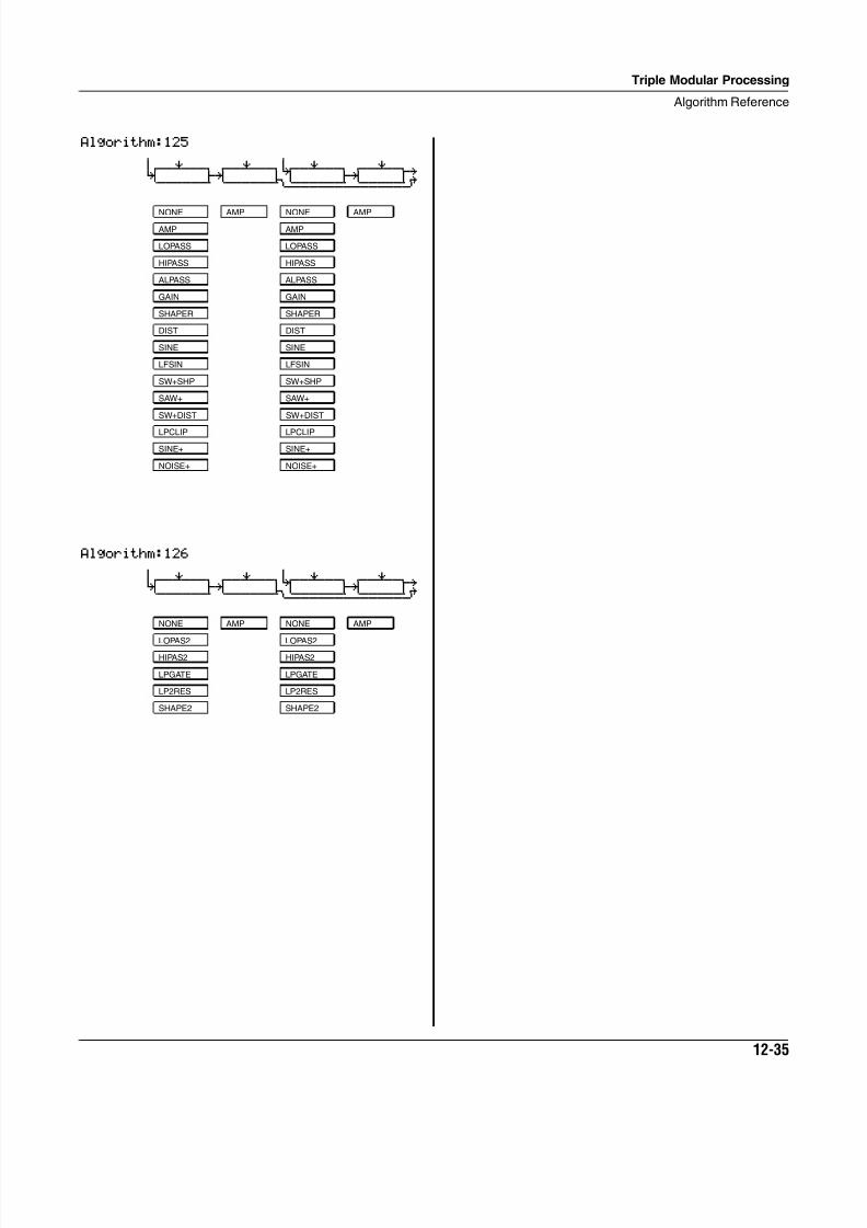
8/21/2019 MR_K2661
http://slidepdf.com/reader/full/mrk2661 375/499
Triple Modular Processing
Algorithm Reference
12-35
Algorithm:125 6 6
0wwerwwtqwwerwwt7wwerwwtqwwerwty K gk JU gk uÓ CVVVVVVBCVVVVVVM<>>>>>>S<>>>>>S»
Algorithm:126 6 6
0wwerwwtqwwerwwt7wwerwwtqwwerwty K gk JU gk uÓ CVVVVVVBCVVVVVVM<>>>>>>S<>>>>>S»
NONE AMP NONE AMP
AMP AMP
LOPASS LOPASS
HIPASS HIPASS
ALPASS ALPASS
GAIN GAIN
SHAPER SHAPER
DIST DIST
SINE SINE
LFSIN LFSIN
SW+SHP SW+SHP
SAW+ SAW+
SW+DIST SW+DIST
LPCLIP LPCLIP
SINE+ SINE+
NOISE+ NOISE+
NONE AMP NONE AMP
LOPAS2 LOPAS2
HIPAS2 HIPAS2
LPGATE LPGATE
LP2RES LP2RES
SHAPE2 SHAPE2
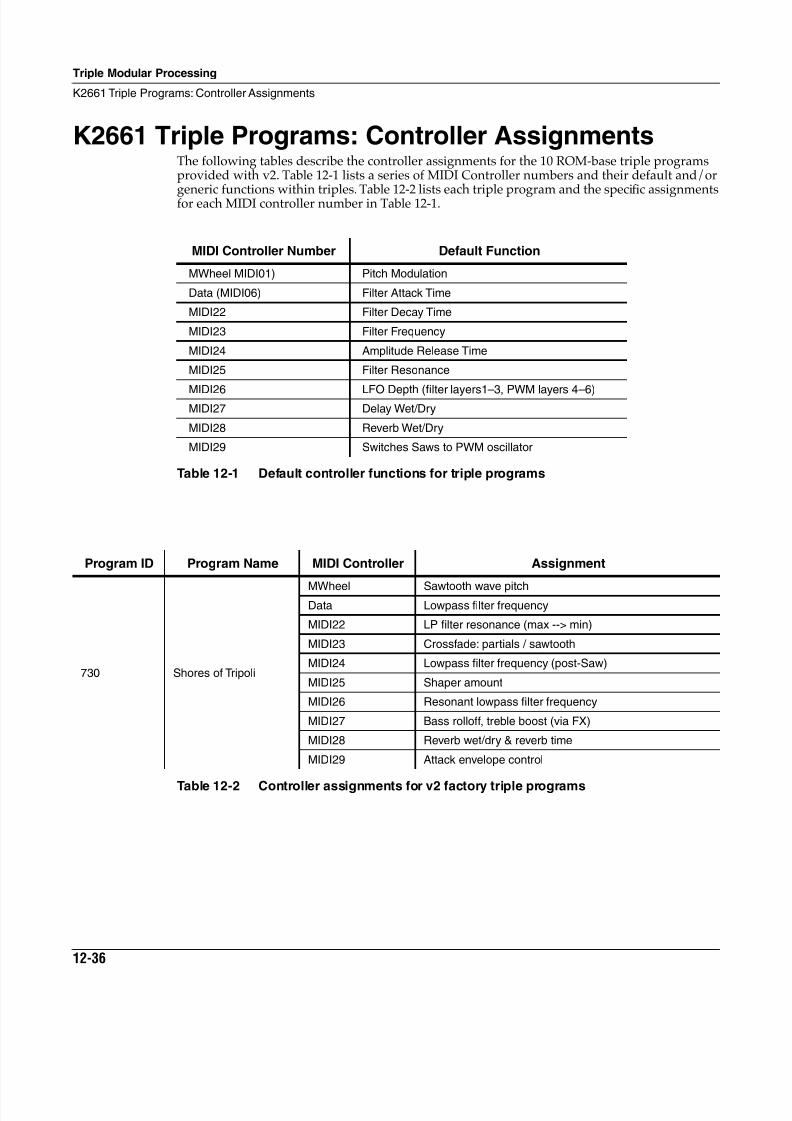
8/21/2019 MR_K2661
http://slidepdf.com/reader/full/mrk2661 376/499
12-36
Triple Modular Processing
K2661 Triple Programs: Controller Assignments
K2661 Triple Programs: Controller AssignmentsThe following tables describe the controller assignments for the 10 ROM-base triple programsprovided with v2. Table 12-1 lists a series of MIDI Controller numbers and their default and/or
generic functions within triples. Table 12-2 lists each triple program and the specifi
c assignmentsfor each MIDI controller number in Table 12-1.
MIDI Controller Number Default Function
MWheel MIDI01) Pitch Modulation
Data (MIDI06) Filter Attack Time
MIDI22 Filter Decay Time
MIDI23 Filter Frequency
MIDI24 Amplitude Release Time
MIDI25 Filter Resonance
MIDI26 LFO Depth (filter layers1–3, PWM layers 4–6)MIDI27 Delay Wet/Dry
MIDI28 Reverb Wet/Dry
MIDI29 Switches Saws to PWM oscillator
Table 12-1 Default controller functions for triple programs
Program ID Program Name MIDI Controller Assignment
730 Shores of Tripoli
MWheel Sawtooth wave pitchData Lowpass filter frequency
MIDI22 LP filter resonance (max --> min)
MIDI23 Crossfade: partials / sawtooth
MIDI24 Lowpass filter frequency (post-Saw)
MIDI25 Shaper amount
MIDI26 Resonant lowpass filter frequency
MIDI27 Bass rolloff, treble boost (via FX)
MIDI28 Reverb wet/dry & reverb time
MIDI29 Attack envelope control
Table 12-2 Controller assignments for v2 factory triple programs
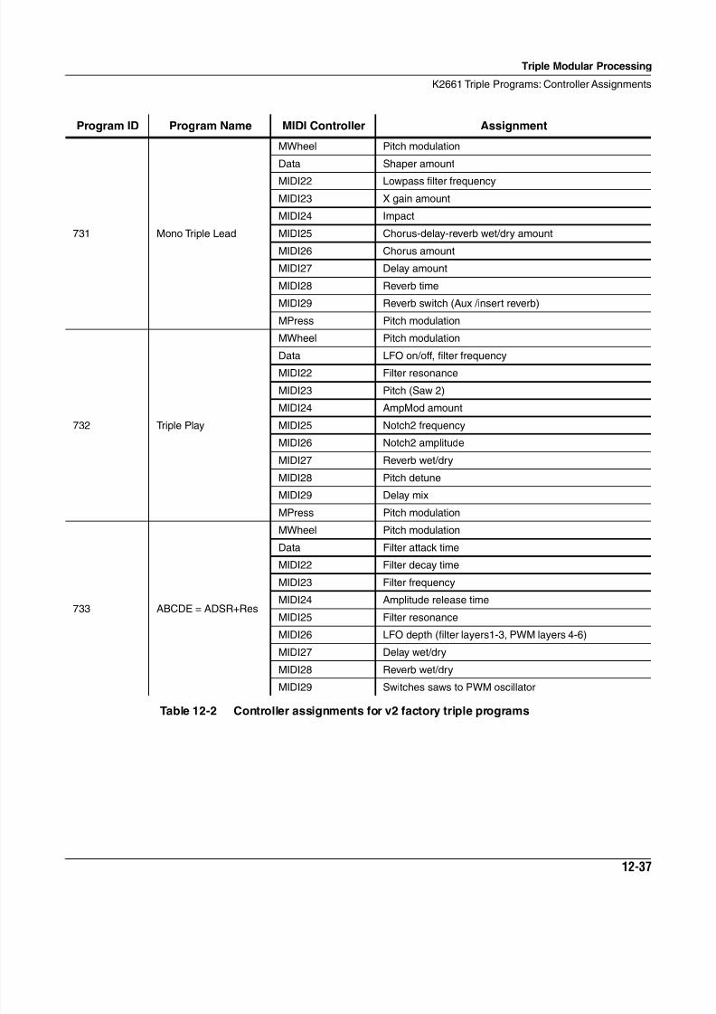
8/21/2019 MR_K2661
http://slidepdf.com/reader/full/mrk2661 377/499
Triple Modular Processing
K2661 Triple Programs: Controller Assignments
12-37
731 Mono Triple Lead
MWheel Pitch modulation
Data Shaper amount
MIDI22 Lowpass filter frequency
MIDI23 X gain amount
MIDI24 Impact
MIDI25 Chorus-delay-reverb wet/dry amount
MIDI26 Chorus amount
MIDI27 Delay amount
MIDI28 Reverb time
MIDI29 Reverb switch (Aux /insert reverb)
MPress Pitch modulation
732 Triple Play
MWheel Pitch modulation
Data LFO on/off, filter frequency
MIDI22 Filter resonance
MIDI23 Pitch (Saw 2)
MIDI24 AmpMod amount
MIDI25 Notch2 frequency
MIDI26 Notch2 amplitude
MIDI27 Reverb wet/dry
MIDI28 Pitch detune
MIDI29 Delay mix
MPress Pitch modulation
733 ABCDE = ADSR+Res
MWheel Pitch modulationData Filter attack time
MIDI22 Filter decay time
MIDI23 Filter frequency
MIDI24 Amplitude release time
MIDI25 Filter resonance
MIDI26 LFO depth (filter layers1-3, PWM layers 4-6)
MIDI27 Delay wet/dry
MIDI28 Reverb wet/dry
MIDI29 Switches saws to PWM oscillator
Program ID Program Name MIDI Controller Assignment
Table 12-2 Controller assignments for v2 factory triple programs
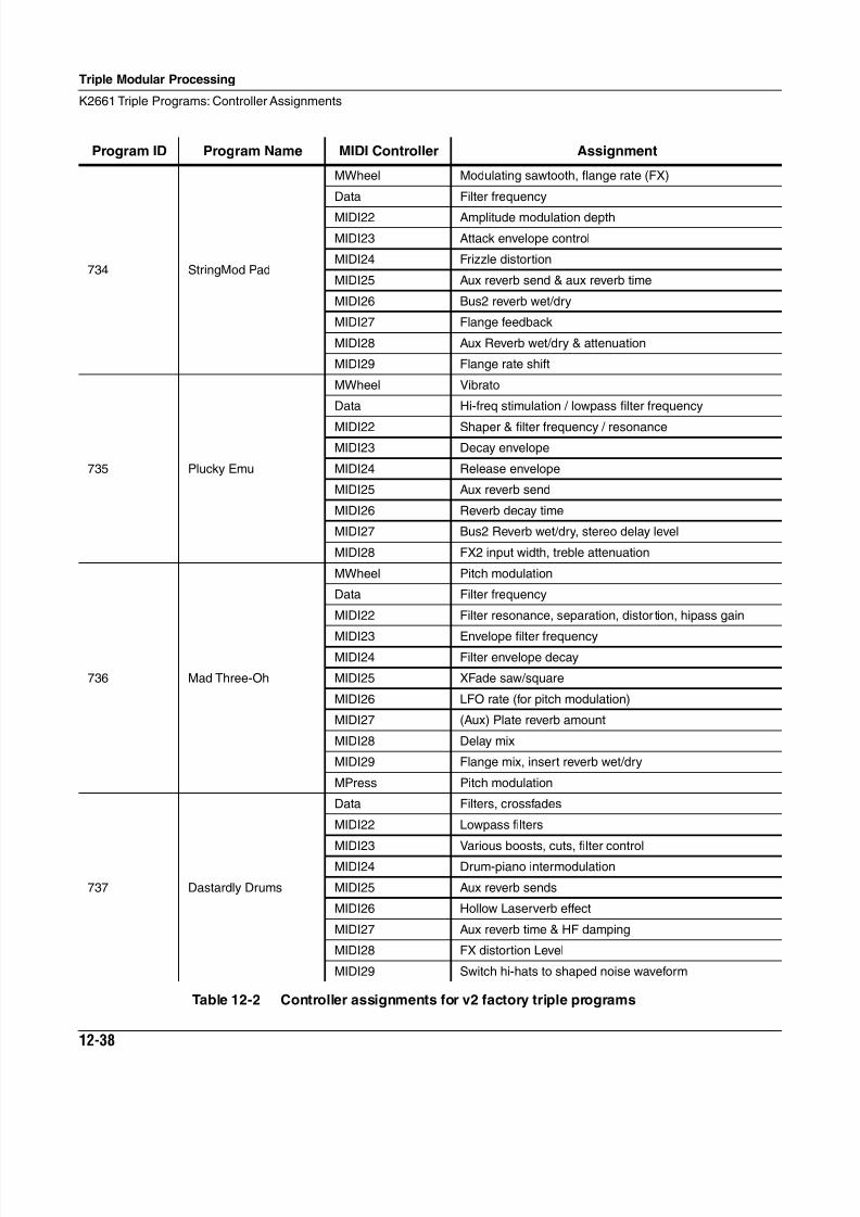
8/21/2019 MR_K2661
http://slidepdf.com/reader/full/mrk2661 378/499
12-38
Triple Modular Processing
K2661 Triple Programs: Controller Assignments
734 StringMod Pad
MWheel Modulating sawtooth, flange rate (FX)
Data Filter frequency
MIDI22 Amplitude modulation depth
MIDI23 Attack envelope control
MIDI24 Frizzle distortion
MIDI25 Aux reverb send & aux reverb time
MIDI26 Bus2 reverb wet/dry
MIDI27 Flange feedback
MIDI28 Aux Reverb wet/dry & attenuation
MIDI29 Flange rate shift
735 Plucky Emu
MWheel Vibrato
Data Hi-freq stimulation / lowpass filter frequency
MIDI22 Shaper & filter frequency / resonance
MIDI23 Decay envelope
MIDI24 Release envelope
MIDI25 Aux reverb send
MIDI26 Reverb decay time
MIDI27 Bus2 Reverb wet/dry, stereo delay level
MIDI28 FX2 input width, treble attenuation
736 Mad Three-Oh
MWheel Pitch modulation
Data Filter frequency
MIDI22 Filter resonance, separation, distor tion, hipass gain
MIDI23 Envelope filter frequencyMIDI24 Filter envelope decay
MIDI25 XFade saw/square
MIDI26 LFO rate (for pitch modulation)
MIDI27 (Aux) Plate reverb amount
MIDI28 Delay mix
MIDI29 Flange mix, insert reverb wet/dry
MPress Pitch modulation
737 Dastardly Drums
Data Filters, crossfades
MIDI22 Lowpass filters
MIDI23 Various boosts, cuts, filter control
MIDI24 Drum-piano intermodulation
MIDI25 Aux reverb sends
MIDI26 Hollow Laserverb effect
MIDI27 Aux reverb time & HF damping
MIDI28 FX distortion Level
MIDI29 Switch hi-hats to shaped noise waveform
Program ID Program Name MIDI Controller Assignment
Table 12-2 Controller assignments for v2 factory triple programs
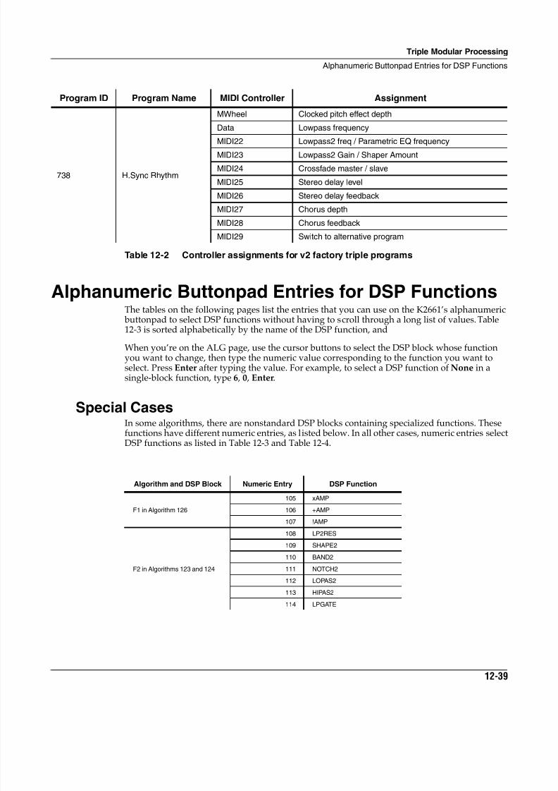
8/21/2019 MR_K2661
http://slidepdf.com/reader/full/mrk2661 379/499
Triple Modular Processing
Alphanumeric Buttonpad Entries for DSP Functions
12-39
Alphanumeric Buttonpad Entries for DSP FunctionsThe tables on the following pages list the entries that you can use on the K2661’s alphanumeric buttonpad to select DSP functions without having to scroll through a long list of values. Table12-3 is sorted alphabetically by the name of the DSP function, and
When you’re on the ALG page, use the cursor buttons to select the DSP block whose functionyou want to change, then type the numeric value corresponding to the function you want toselect. Press Enter after typing the value. For example, to select a DSP function of None in asingle-block function, type 6 , 0 , Enter.
Special CasesIn some algorithms, there are nonstandard DSP blocks containing specialized functions. Thesefunctions have different numeric entries, as listed below. In all other cases, numeric entries selectDSP functions as listed in Table 12-3 and Table 12-4.
738 H.Sync Rhythm
MWheel Clocked pitch effect depth
Data Lowpass frequency
MIDI22 Lowpass2 freq / Parametric EQ frequency
MIDI23 Lowpass2 Gain / Shaper Amount
MIDI24 Crossfade master / slave
MIDI25 Stereo delay level
MIDI26 Stereo delay feedback
MIDI27 Chorus depth
MIDI28 Chorus feedback
MIDI29 Switch to alternative program
Algorithm and DSP Block Numeric Entry DSP Function
F1 in Algorithm 126
105 xAMP
106 +AMP
107 !AMP
F2 in Algorithms 123 and 124
108 LP2RES
109 SHAPE2
110 BAND2
111 NOTCH2
112 LOPAS2
113 HIPAS2
114 LPGATE
Program ID Program Name MIDI Controller Assignment
Table 12-2 Controller assignments for v2 factory triple programs
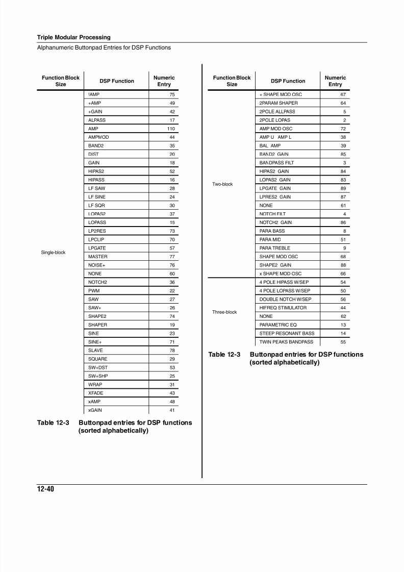
8/21/2019 MR_K2661
http://slidepdf.com/reader/full/mrk2661 380/499
12-40
Triple Modular Processing
Alphanumeric Buttonpad Entries for DSP Functions
Function Block
SizeDSP Function
Numeric
Entry
Single-block
!AMP 75
+AMP 49
+GAIN 42
ALPASS 17
AMP 110
AMPMOD 44
BAND2 35
DIST 20
GAIN 18
HIPAS2 52
HIPASS 16
LF SAW 28
LF SINE 24
LF SQR 30
LOPAS2 37
LOPASS 15
LP2RES 73
LPCLIP 70
LPGATE 57
MASTER 77
NOISE+ 76
NONE 60
NOTCH2 36
PWM 22
SAW 27SAW+ 26
SHAPE2 74
SHAPER 19
SINE 23
SINE+ 71
SLAVE 78
SQUARE 29
SW+DST 53
SW+SHP 25
WRAP 31
XFADE 43
xAMP 48
xGAIN 41
Table 12-3 Buttonpad entries for DSP functions(sorted alphabetically)
Function Block
SizeDSP Function
Numeric
Entry
Two-block
+ SHAPE MOD OSC 67
2PARAM SHAPER 64
2POLE ALLPASS 5
2POLE LOPAS 2
AMP MOD OSC 72
AMP U AMP L 38
BAL AMP 39
BAND2 GAIN 85
BANDPASS FILT 3
HIPAS2 GAIN 84
LOPAS2 GAIN 83
LPGATE GAIN 89
LPRES2 GAIN 87
NONE 61
NOTCH FILT 4
NOTCH2 GAIN 86
PARA BASS 8
PARA MID 51
PARA TREBLE 9
SHAPE MOD OSC 68
SHAPE2 GAIN 88
x SHAPE MOD OSC 66
Three-block
4 POLE HIPASS W/SEP 54
4 POLE LOPASS W/SEP 50
DOUBLE NOTCH W/SEP 56HIFREQ STIMULATOR 44
NONE 62
PARAMETRIC EQ 13
STEEP RESONANT BASS 14
TWIN PEAKS BANDPASS 55
Table 12-3 Buttonpad entries for DSP functions(sorted alphabetically)
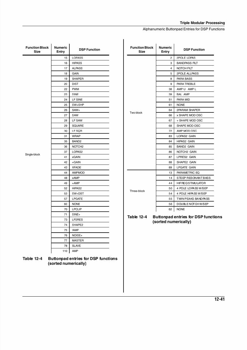
8/21/2019 MR_K2661
http://slidepdf.com/reader/full/mrk2661 381/499
Triple Modular Processing
Alphanumeric Buttonpad Entries for DSP Functions
12-41
Function Block
Size
Numeric
EntryDSP Function
Single-block
15 LOPASS
16 HIPASS
17 ALPASS
18 GAIN
19 SHAPER
20 DIST
22 PWM
23 SINE
24 LF SINE
25 SW+SHP
26 SAW+
27 SAW
28 LF SAW
29 SQUARE
30 LF SQR
31 WRAP
35 BAND2
36 NOTCH2
37 LOPAS2
41 xGAIN
42 +GAIN
43 XFADE
44 AMPMOD
48 xAMP
49 +AMP52 HIPAS2
53 SW+DST
57 LPGATE
60 NONE
70 LPCLIP
71 SINE+
73 LP2RES
74 SHAPE2
75 !AMP
76 NOISE+
77 MASTER
78 SLAVE
110 AMP
Table 12-4 Buttonpad entries for DSP functions(sorted numerically)
Function Block
Size
Numeric
EntryDSP Function
Two-block
2 2POLE LOPAS
3 BANDPASS FILT
4 NOTCH FILT
5 2POLE ALLPASS
8 PARA BASS
9 PARA TREBLE
38 AMP U AMP L
39 BAL AMP
51 PARA MID
61 NONE
64 2PARAM SHAPER
66 x SHAPE MOD OSC
67 + SHAPE MOD OSC
68 SHAPE MOD OSC
72 AMP MOD OSC
83 LOPAS2 GAIN
84 HIPAS2 GAIN
85 BAND2 GAIN
86 NOTCH2 GAIN
87 LPRES2 GAIN
88 SHAPE2 GAIN
89 LPGATE GAIN
Three-block
13 PARAMETRIC EQ
14 STEEP RESONANT BASS
44 HIFREQ STIMULATOR50 4 POLE LOPASS W/SEP
54 4 POLE HIPASS W/SEP
55 TWIN PEAKS BANDPASS
56 DOUBLE NOTCH W/SEP
62 NONE
Table 12-4 Buttonpad entries for DSP functions(sorted numerically)
8/21/2019 MR_K2661
http://slidepdf.com/reader/full/mrk2661 382/499
12-42
Triple Modular Processing
Alphanumeric Buttonpad Entries for DSP Functions
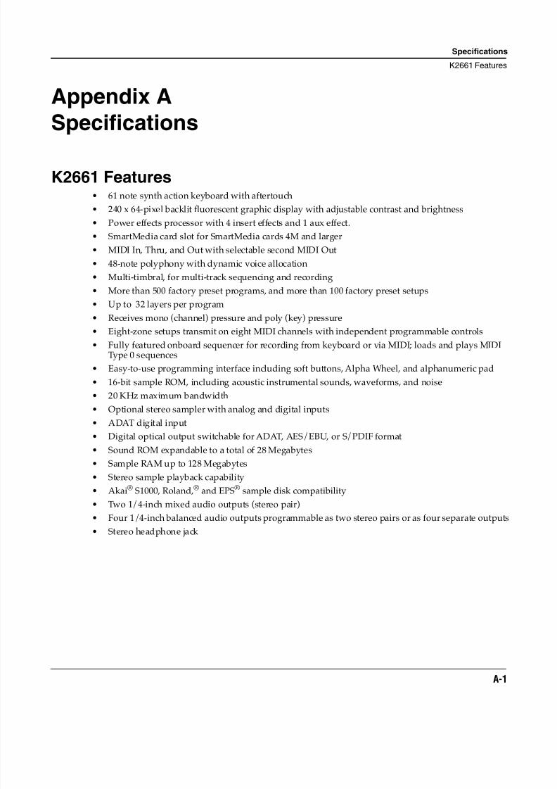
8/21/2019 MR_K2661
http://slidepdf.com/reader/full/mrk2661 383/499
Specifications
K2661 Features
A-1
Appendix A
Specifications
K2661 Features• 61 note synth action keyboard with aftertouch
• 240 x 64-pixel backlit fluorescent graphic display with adjustable contrast and brightness
• Power effects processor with 4 insert effects and 1 aux effect.
• SmartMedia card slot for SmartMedia cards 4M and larger
• MIDI In, Thru, and Out with selectable second MIDI Out
• 48-note polyphony with dynamic voice allocation
• Multi-timbral, for multi-track sequencing and recording• More than 500 factory preset programs, and more than 100 factory preset setups
• Up to 32 layers per program
• Receives mono (channel) pressure and poly (key) pressure
• Eight-zone setups transmit on eight MIDI channels with independent programmable controls
• Fully featured onboard sequencer for recording from keyboard or via MIDI; loads and plays MIDIType 0 sequences
• Easy-to-use programming interface including soft buttons, Alpha Wheel, and alphanumeric pad
• 16-bit sample ROM, including acoustic instrumental sounds, waveforms, and noise
• 20 KHz maximum bandwidth
• Optional stereo sampler with analog and digital inputs
• ADAT digital input
• Digital optical output switchable for ADAT, AES/EBU, or S/PDIF format
• Sound ROM expandable to a total of 28 Megabytes
• Sample RAM up to 128 Megabytes
• Stereo sample playback capability
• Akai® S1000, Roland,® and EPS® sample disk compatibility
• Two 1/4-inch mixed audio outputs (stereo pair)
• Four 1/4-inch balanced audio outputs programmable as two stereo pairs or as four separate outputs
• Stereo headphone jack
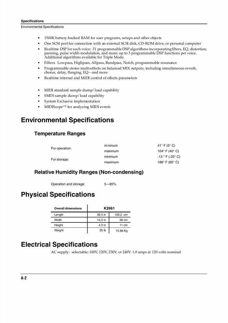
8/21/2019 MR_K2661
http://slidepdf.com/reader/full/mrk2661 384/499
A-2
Specifications
Environmental Specifications
• 1500K battery-backed RAM for user programs, setups and other objects
• One SCSI port for connection with an external SCSI disk, CD-ROM drive, or personal computer
• Realtime DSP for each voice: 31 programmable DSP algorithms incorporatingfilters, EQ, distortion,panning, pulse width modulation, and more; up to 3 programmable DSP functions per voice.
Additional algorithms available for Triple Mode.• Filters: Lowpass, Highpass, Allpass, Bandpass, Notch, programmable resonance
• Programmable stereo multi-effects on balanced MIX outputs, including simultaneous reverb,chorus, delay, flanging, EQ—and more
• Realtime internal and MIDI control of effects parameters
• MIDI standard sample dump/load capability
• SMDI sample dump/load capability
• System Exclusive implementation
• MIDIScope™ for analyzing MIDI events
Environmental Specifications
Temperature Ranges
Relative Humidity Ranges (Non-condensing)
Physical Specifications
Electrical SpecificationsAC supply: selectable; 100V, 120V, 230V, or 240V. 1.0 amps at 120 volts nominal
For operation:minimum 41° F (5° C)
maximum 104° F (40° C)
For storage:minimum -13 ° F (-25° C)
maximum 186° F (85° C)
Operation and storage: 5—95%
Overall dimensions K2661
Length 39.4 in 100.2 cm
Width 14.2 in 36 cm
Height 4.3 in 11 cmWeight 35 lb 15.86 Kg
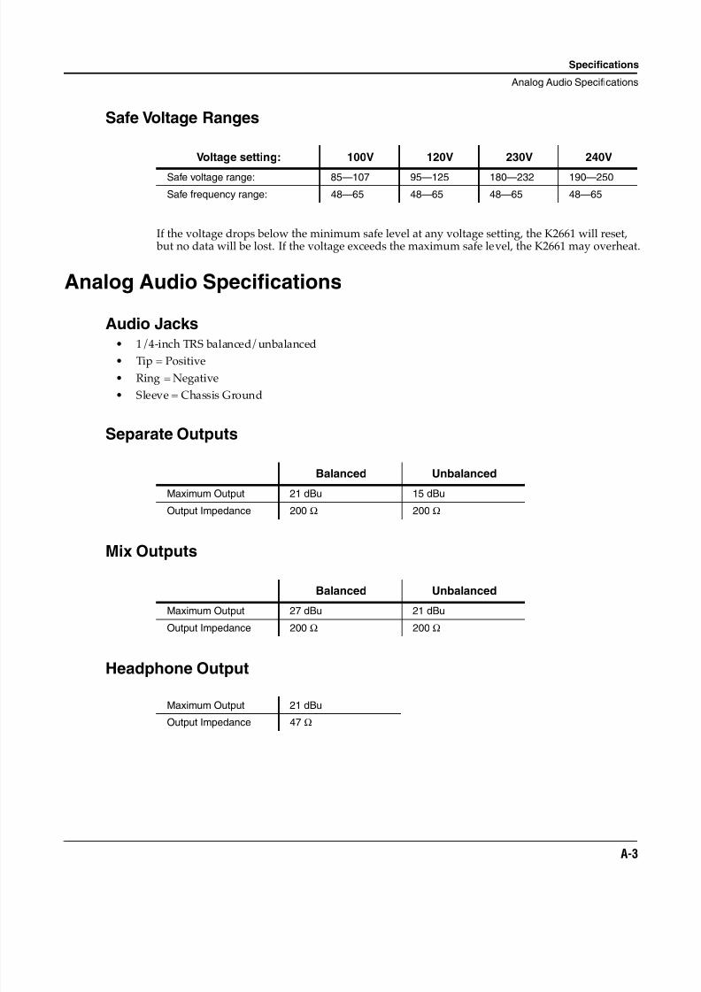
8/21/2019 MR_K2661
http://slidepdf.com/reader/full/mrk2661 385/499
Specifications
Analog Audio Specifications
A-3
Safe Voltage Ranges
If the voltage drops below the minimum safe level at any voltage setting, the K2661 will reset, but no data will be lost. If the voltage exceeds the maximum safe level, the K2661 may overheat.
Analog Audio Specifications
Audio Jacks
• 1/4-inch TRS balanced/unbalanced• Tip = Positive
• Ring = Negative
• Sleeve = Chassis Ground
Separate Outputs
Mix Outputs
Headphone Output
Voltage setting: 100V 120V 230V 240V
Safe voltage range: 85—107 95—125 180—232 190—250
Safe frequency range: 48—65 48—65 48—65 48—65
Balanced Unbalanced
Maximum Output 21 dBu 15 dBu
Output Impedance 200 Ω 200 Ω
Balanced Unbalanced
Maximum Output 27 dBu 21 dBu
Output Impedance 200 Ω 200 Ω
Maximum Output 21 dBu
Output Impedance 47 Ω
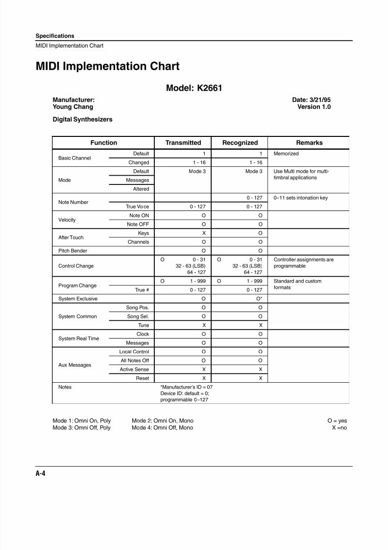
8/21/2019 MR_K2661
http://slidepdf.com/reader/full/mrk2661 386/499
A-4
Specifications
MIDI Implementation Chart
MIDI Implementation Chart
Model: K2661
Manufacturer: Date: 3/21/95Young Chang Version 1.0
Digital Synthesizers
Mode 1: Omni On, Poly Mode 2: Omni On, Mono O = yes
Mode 3: Omni Off, Poly Mode 4: Omni Off, Mono X =no
Function Transmitted Recognized Remarks
Basic ChannelDefault 1 1 Memorized
Changed 1 - 16 1 - 16
Mode
Default Mode 3 Mode 3 Use Multi mode for multi-
timbral applicationsMessages
Altered
Note Number0 - 127 0–11 sets intonation key
True Voice 0 - 127 0 - 127
VelocityNote ON O O
Note OFF O O
After TouchKeys X O
Channels O O
Pitch Bender O O
Control Change
O 0 - 31
32 - 63 (LSB)
64 - 127
O 0 - 31
32 - 63 (LSB)
64 - 127
Controller assignments are
programmable
Program ChangeO 1 - 999 O 1 - 999 Standard and custom
formatsTrue # 0 - 127 0 - 127
System Exclusive O O*
System Common
Song Pos. O O
Song Sel. O O
Tune X X
System Real TimeClock O O
Messages O O
Aux Messages
Local Control O O
All Notes Off O O
Active Sense X X
Reset X X
Notes *Manufacturer’s ID = 07Device ID: default = 0;
programmable 0–127
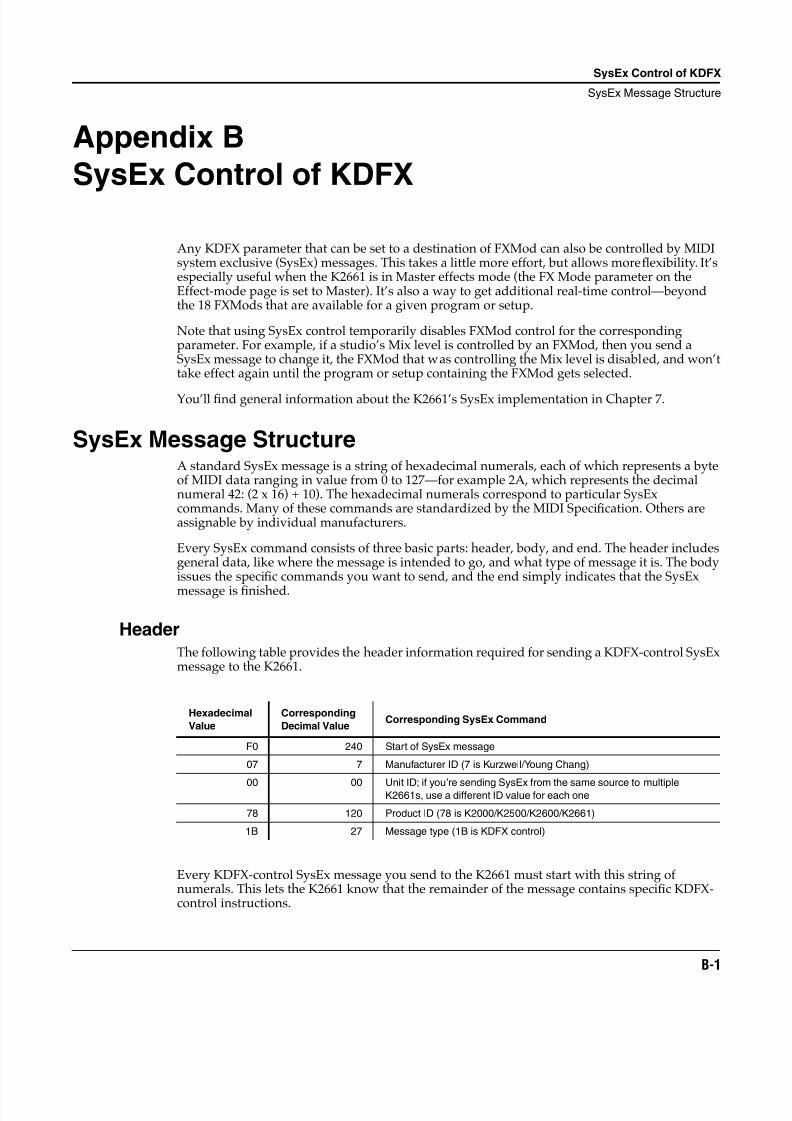
8/21/2019 MR_K2661
http://slidepdf.com/reader/full/mrk2661 387/499
SysEx Control of KDFX
SysEx Message Structure
B-1
Appendix B
SysEx Control of KDFX
Any KDFX parameter that can be set to a destination of FXMod can also be controlled by MIDIsystem exclusive (SysEx) messages. This takes a little more effort, but allows more flexibility. It’sespecially useful when the K2661 is in Master effects mode (the FX Mode parameter on theEffect-mode page is set to Master). It’s also a way to get additional real-time control—beyondthe 18 FXMods that are available for a given program or setup.
Note that using SysEx control temporarily disables FXMod control for the correspondingparameter. For example, if a studio’s Mix level is controlled by an FXMod, then you send aSysEx message to change it, the FXMod that was controlling the Mix level is disabled, and won’ttake effect again until the program or setup containing the FXMod gets selected.
You’ll find general information about the K2661’s SysEx implementation in Chapter 7.
SysEx Message StructureA standard SysEx message is a string of hexadecimal numerals, each of which represents a byteof MIDI data ranging in value from 0 to 127—for example 2A, which represents the decimalnumeral 42: (2 x 16) + 10). The hexadecimal numerals correspond to particular SysExcommands. Many of these commands are standardized by the MIDI Specification. Others areassignable by individual manufacturers.
Every SysEx command consists of three basic parts: header, body, and end. The header includesgeneral data, like where the message is intended to go, and what type of message it is. The bodyissues the specific commands you want to send, and the end simply indicates that the SysEx
message is finished.
HeaderThe following table provides the header information required for sending a KDFX-control SysExmessage to the K2661.
Every KDFX-control SysEx message you send to the K2661 must start with this string ofnumerals. This lets the K2661 know that the remainder of the message contains specific KDFX-control instructions.
Hexadecimal
Value
Corresponding
Decimal ValueCorresponding SysEx Command
F0 240 Start of SysEx message
07 7 Manufacturer ID (7 is Kurzweil/Young Chang)
00 00 Unit ID; if you’re sending SysEx from the same source to multipleK2661s, use a different ID value for each one
78 120 Product ID (78 is K2000/K2500/K2600/K2661)
1B 27 Message type (1B is KDFX control)
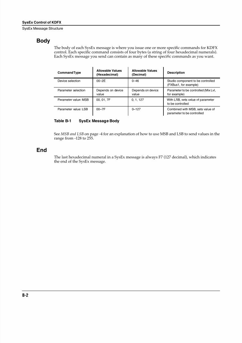
8/21/2019 MR_K2661
http://slidepdf.com/reader/full/mrk2661 388/499
B-2
SysEx Control of KDFX
SysEx Message Structure
BodyThe body of each SysEx message is where you issue one or more specific commands for KDFXcontrol. Each specific command consists of four bytes (a string of four hexadecimal numerals).Each SysEx message you send can contain as many of these specific commands as you want.
See MSB and LSB on page -4 for an explanation of how to use MSB and LSB to send values in therange from -128 to 255.
EndThe last hexadecimal numeral in a SysEx message is always F7 (127 decimal), which indicatesthe end of the SysEx message.
Command TypeAllowable Values
(Hexadecimal)
Allowable Values
(Decimal)Description
Device selection 00–2E 0–46 Studio component to be controlled
(FXBus1, for example)
Parameter selection Depends on device
value
Depends on device
value
Parameter to be controlled (Mix Lvl,
for example)
Parameter value: MSB 00, 01, 7F 0, 1, 127 With LSB, sets value of parameter
to be controlled
Parameter value: LSB 00–7F 0–127 Combined with MSB, sets value of
parameter to be controlled
Table B-1 SysEx Message Body
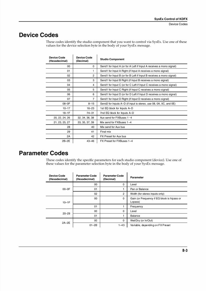
8/21/2019 MR_K2661
http://slidepdf.com/reader/full/mrk2661 389/499
SysEx Control of KDFX
Device Codes
B-3
Device CodesThese codes identify the studio component that you want to control via SysEx. Use one of thesevalues for the device selection byte in the body of your SysEx message.
Parameter CodesThese codes identify the specific parameters for each studio component (device). Use one ofthese values for the parameter selection byte in the body of your SysEx message.
Device Code
(Hexadecimal)
Device Code
(Decimal)Studio Component
00 0 Send1 for Input A (or for A Left if Input A receives a mono signal)
01 1 Send1 for Input A Right (if Input A receives a mono signal)
02 2 Send1 for Input B (or for B Left if Input B receives a mono signal)
03 3 Send1 for Input B Right (if Input B receives a mono signal)
04 4 Send1 for Input C (or for C Left if Input C receives a mono signal)
05 5 Send1 for Input C Right (if Input C receives a mono signal)
06 6 Send1 for Input D (or for D Left if Input D receives a mono signal)
07 7 Send1 for Input D Right (if Input D receives a mono signal)
08–0F 8–15 Send2 for Inputs A–D (if input is stereo, use 08, 0A, 0C, and 0E)
10–17 16–23 1st EQ block for Inputs A–D
18–1F 24–31 2nd EQ block for Inputs A–D
20, 22, 24, 26 32, 34, 36, 38 Aux send for FXBuses 1–4
21, 23, 25, 27 33, 35, 37, 39 Mix send for FXBuses 1–4
28 40 Mix send for Aux bus
29 41 Final mix
2A 42 FX Preset for Aux bus
2B–2E 43–46 FX Preset for FXBuses 1–4
Device Code
(Hexadecimal)
Parameter Code
(Hexadecimal)
Parameter Code
(Decimal)Parameter
00–0F
00 0 Level
01 1 Pan or Balance
02 2 Width (for stereo inputs only)
10–1F
00 0 Gain (or Frequency if EQ block is hipass or
Lopass)
01 1 Frequency
20–2900 0 Level
01 1 Balance
2A–2E00 0 Wet/Dry (or In/Out)
01–2B 1–43 Variable, depending on FX Preset
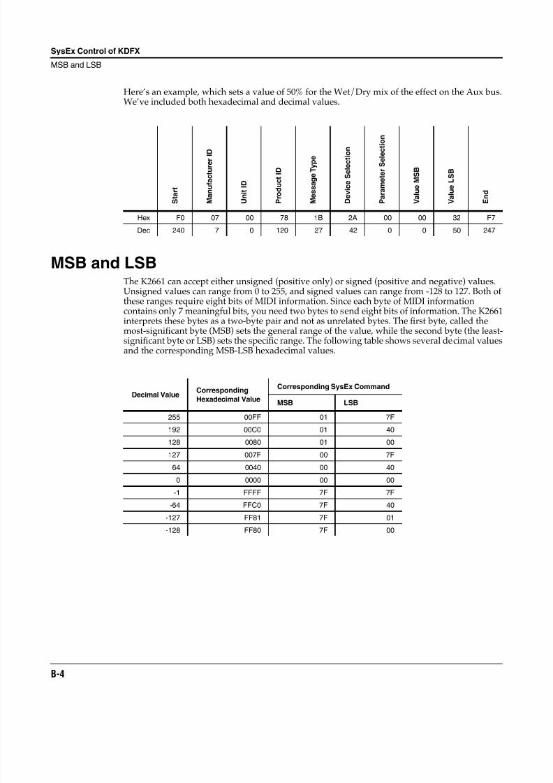
8/21/2019 MR_K2661
http://slidepdf.com/reader/full/mrk2661 390/499
B-4
SysEx Control of KDFX
MSB and LSB
Here’s an example, which sets a value of 50% for the Wet/Dry mix of the effect on the Aux bus.We’ve included both hexadecimal and decimal values.
MSB and LSBThe K2661 can accept either unsigned (positive only) or signed (positive and negative) values.Unsigned values can range from 0 to 255, and signed values can range from -128 to 127. Both ofthese ranges require eight bits of MIDI information. Since each byte of MIDI informationcontains only 7 meaningful bits, you need two bytes to send eight bits of information. The K2661interprets these bytes as a two-byte pair and not as unrelated bytes. The first byte, called themost-significant byte (MSB) sets the general range of the value, while the second byte (the least-significant byte or LSB) sets the specific range. The following table shows several decimal valuesand the corresponding MSB-LSB hexadecimal values.
S t a r t
M a n u f a c t u r e r I D
U n i t I D
P r o d u c t I D
M e s s a g e T y p e
D e v i c e S e l e c t i o n
P a r a m e t e r S e l e c t i o n
V a l u e M S B
V a l u e L S B
E n d
Hex F0 07 00 78 1B 2A 00 00 32 F7
Dec 240 7 0 120 27 42 0 0 50 247
Decimal ValueCorresponding
Hexadecimal Value
Corresponding SysEx Command
MSB LSB
255 00FF 01 7F
192 00C0 01 40
128 0080 01 00
127 007F 00 7F
64 0040 00 40
0 0000 00 00
-1 FFFF 7F 7F
-64 FFC0 7F 40
-127 FF81 7F 01
-128 FF80 7F 00
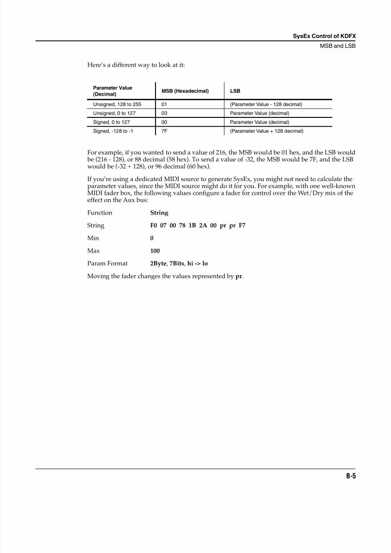
8/21/2019 MR_K2661
http://slidepdf.com/reader/full/mrk2661 391/499
SysEx Control of KDFX
MSB and LSB
B-5
Here’s a different way to look at it:
For example, if you wanted to send a value of 216, the MSB would be 01 hex, and the LSB would be (216 - 128), or 88 decimal (58 hex). To send a value of -32, the MSB would be 7F, and the LSBwould be (-32 + 128), or 96 decimal (60 hex).
If you’re using a dedicated MIDI source to generate SysEx, you might not need to calculate theparameter values, since the MIDI source might do it for you. For example, with one well-known
MIDI fader box, the following values configure a fader for control over the Wet/Dry mix of theeffect on the Aux bus:
Function String
String F0 07 00 78 1B 2A 00 pr pr F7
Min 0
Max 100
Param Format 2Byte , 7Bits , hi -> lo
Moving the fader changes the values represented by pr.
Parameter Value
(Decimal)
MSB (Hexadecimal) LSB
Unsigned, 128 to 255 01 (Parameter Value - 128 decimal)
Unsigned, 0 to 127 00 Parameter Value (decimal)
Signed, 0 to 127 00 Parameter Value (decimal)
Signed, -128 to -1 7F (Parameter Value + 128 decimal)

8/21/2019 MR_K2661
http://slidepdf.com/reader/full/mrk2661 392/499
B-6
SysEx Control of KDFX
MSB and LSB
8/21/2019 MR_K2661
http://slidepdf.com/reader/full/mrk2661 393/499
Standard K2661 ROM Objects
Groove Setups
C-1
Appendix C
Standard K2661 ROM Objects
The preset programs in the K2661 are organized by instrument category. You’ll find a fewrepresentatives of each instrument sampled, as well as synthesized instrument emulations,commonly used synthesizer timbres, and templates for new programming. We hope you find ita good starting point for your own work.
Groove Setups
Setups 1–30 are Groove Setups. Once you’ve installed the objects, you can access the setups bypressing the Setup button on the front panel of your K2661.
When you are playing a Groove Setup, you can activate a drum pattern (actually a song file) by
pressing any key below C3 (C below middle C). Once triggered, the drum pattern isautomatically held or latched (in other words, you do not need to keep holding the key downfor the groove to continue playing). Most grooves have a bass sound assigned to the left handkeyboard region, as well as some sounds for right hand playing.
Use your K2661’s large ribbon to activate a fill for the groove. (There is one groove that does notfollow this convention, #2, where there is no fill on the ribbon. Instead, a 'toms fill' is activatedwhen you play between C3 and C4 on the keyboard.)
Note: After pressing panic , grooves won't trigger; you must scroll away and then back for thesetup to get the correct entry value.
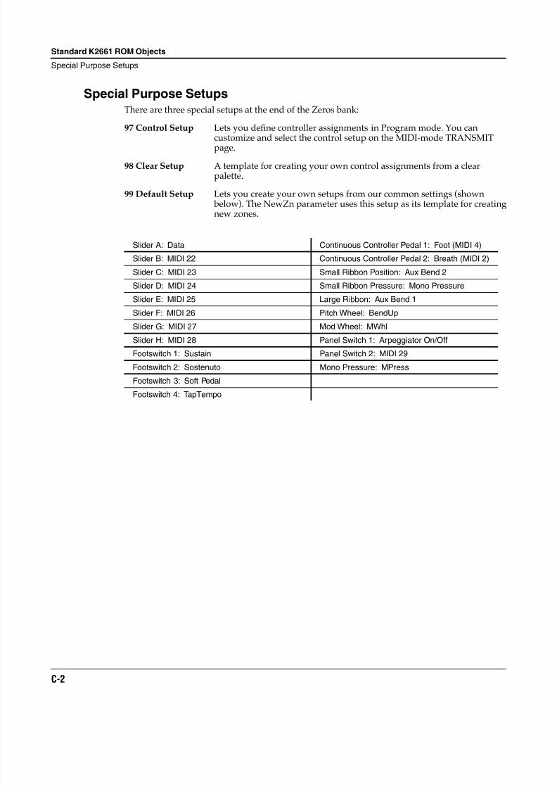
8/21/2019 MR_K2661
http://slidepdf.com/reader/full/mrk2661 394/499
C-2
Standard K2661 ROM Objects
Special Purpose Setups
Special Purpose SetupsThere are three special setups at the end of the Zeros bank:
97 Control Setup Lets you define controller assignments in Program mode. You can
customize and select the control setup on the MIDI-mode TRANSMITpage.
98 Clear Setup A template for creating your own control assignments from a clearpalette.
99 Default Setup Lets you create your own setups from our common settings (shown below). The NewZn parameter uses this setup as its template for creatingnew zones.
Slider A: Data Continuous Controller Pedal 1: Foot (MIDI 4)
Slider B: MIDI 22 Continuous Controller Pedal 2: Breath (MIDI 2)
Slider C: MIDI 23 Small Ribbon Position: Aux Bend 2Slider D: MIDI 24 Small Ribbon Pressure: Mono Pressure
Slider E: MIDI 25 Large Ribbon: Aux Bend 1
Slider F: MIDI 26 Pitch Wheel: BendUp
Slider G: MIDI 27 Mod Wheel: MWhl
Slider H: MIDI 28 Panel Switch 1: Arpeggiator On/Off
Footswitch 1: Sustain Panel Switch 2: MIDI 29
Footswitch 2: Sostenuto Mono Pressure: MPress
Footswitch 3: Soft Pedal
Footswitch 4: TapTempo
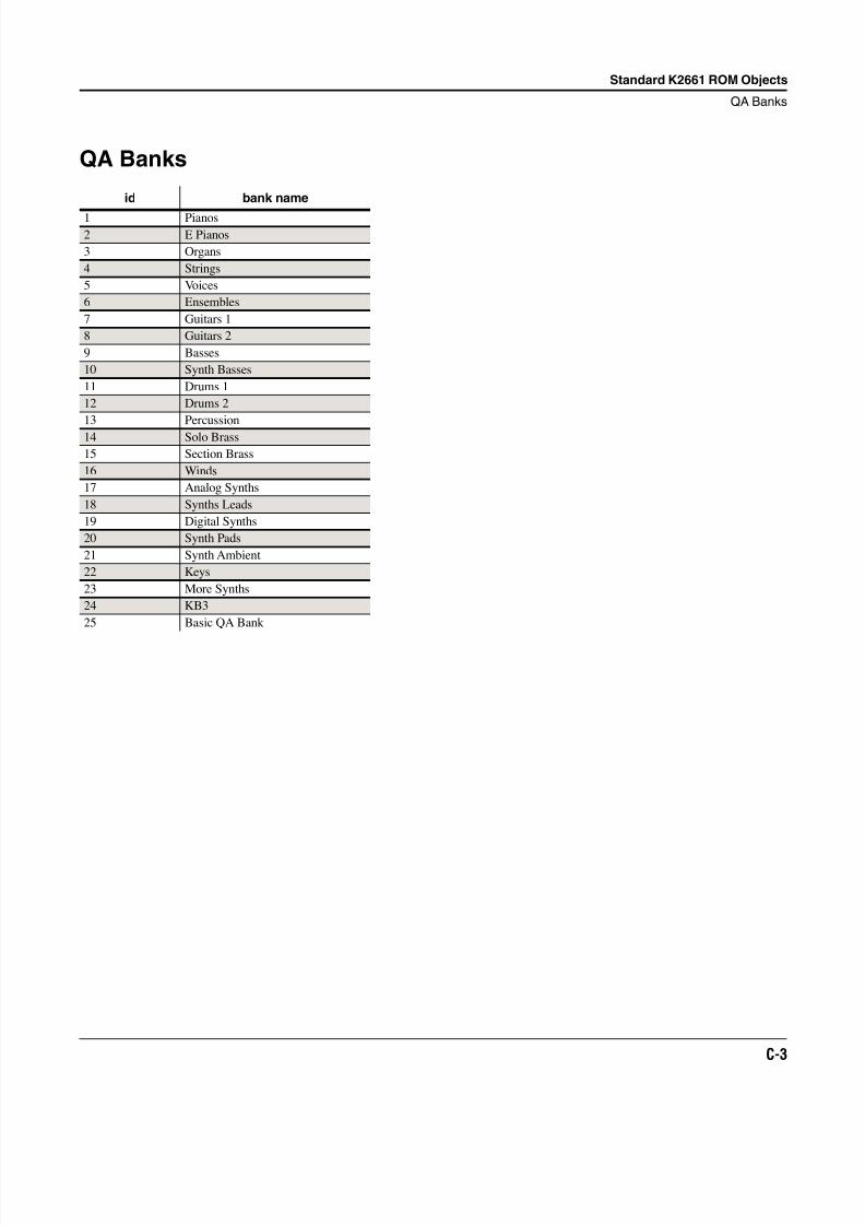
8/21/2019 MR_K2661
http://slidepdf.com/reader/full/mrk2661 395/499
Standard K2661 ROM Objects
QA Banks
C-3
QA Banks
id bank name
1 Pianos
2 E Pianos
3 Organs
4 Strings
5 Voices
6 Ensembles
7 Guitars 1
8 Guitars 2
9 Basses
10 Synth Basses
11 Drums 1
12 Drums 2
13 Percussion
14 Solo Brass
15 Section Brass
16 Winds
17 Analog Synths
18 Synths Leads
19 Digital Synths
20 Synth Pads
21 Synth Ambient
22 Keys
23 More Synths
24 KB3
25 Basic QA Bank
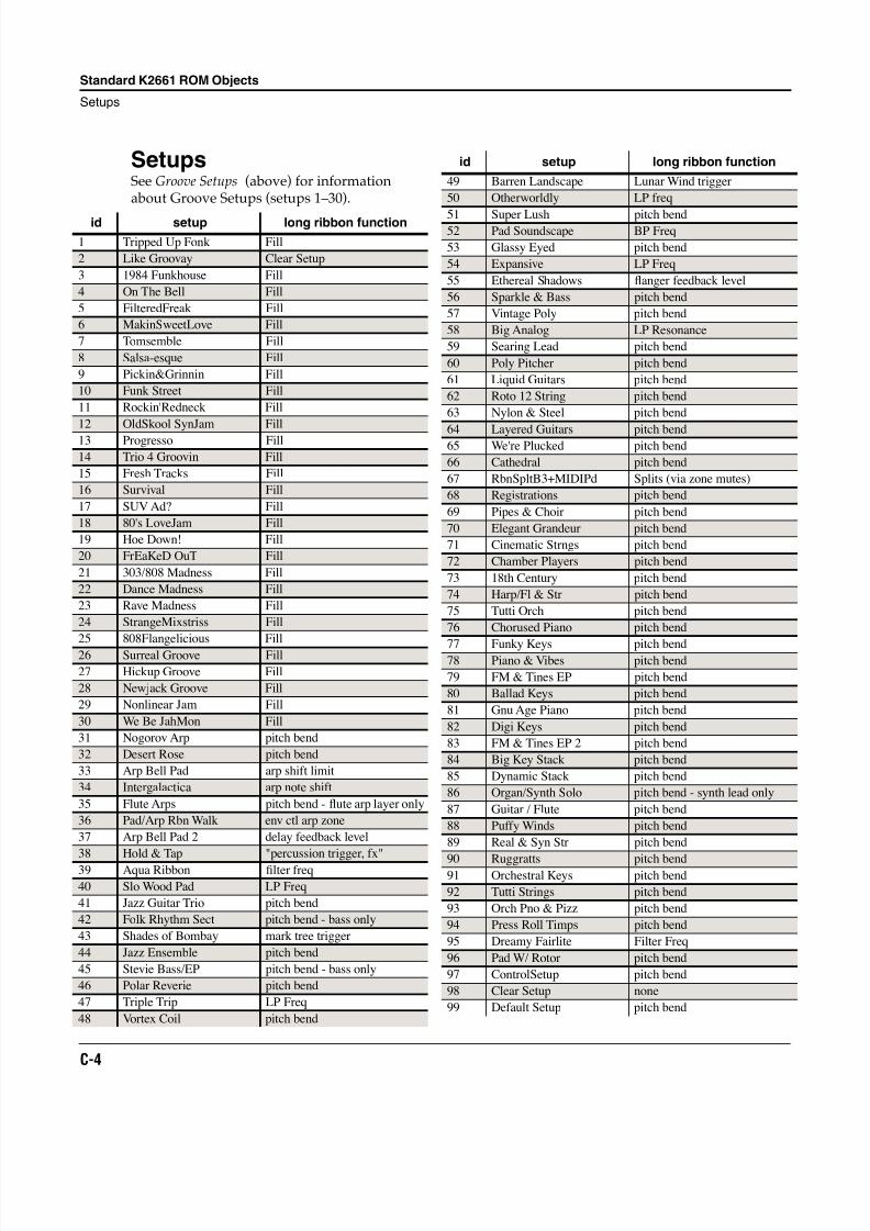
8/21/2019 MR_K2661
http://slidepdf.com/reader/full/mrk2661 396/499
C-4
Standard K2661 ROM Objects
Setups
SetupsSee Groove Setups (above) for informationabout Groove Setups (setups 1–30).
id setup long ribbon function
1 Tripped Up Fonk Fill
2 Like Groovay Clear Setup
3 1984 Funkhouse Fill
4 On The Bell Fill
5 FilteredFreak Fill
6 MakinSweetLove Fill
7 Tomsemble Fill
8 Salsa-esque Fill
9 Pickin&Grinnin Fill
10 Funk Street Fill
11 Rockin'Redneck Fill
12 OldSkool SynJam Fill
13 Progresso Fill
14 Trio 4 Groovin Fill
15 Fresh Tracks Fill
16 Survival Fill
17 SUV Ad? Fill
18 80's LoveJam Fill
19 Hoe Down! Fill
20 FrEaKeD OuT Fill
21 303/808 Madness Fill
22 Dance Madness Fill
23 Rave Madness Fill
24 StrangeMixstriss Fill
25 808Flangelicious Fill
26 Surreal Groove Fill
27 Hickup Groove Fill
28 Newjack Groove Fill
29 Nonlinear Jam Fill
30 We Be JahMon Fill
31 Nogorov Arp pitch bend
32 Desert Rose pitch bend
33 Arp Bell Pad arp shift limit
34 Intergalactica arp note shift
35 Flute Arps pitch bend - flute arp layer only
36 Pad/Arp Rbn Walk env ctl arp zone
37 Arp Bell Pad 2 delay feedback level
38 Hold & Tap "percussion trigger, fx"
39 Aqua Ribbon filter freq
40 Slo Wood Pad LP Freq
41 Jazz Guitar Trio pitch bend
42 Folk Rhythm Sect pitch bend - bass only
43 Shades of Bombay mark tree trigger
44 Jazz Ensemble pitch bend
45 Stevie Bass/EP pitch bend - bass only
46 Polar Reverie pitch bend
47 Triple Trip LP Freq
48 Vortex Coil pitch bend
49 Barren Landscape Lunar Wind trigger
50 Otherworldly LP freq
51 Super Lush pitch bend52 Pad Soundscape BP Freq
53 Glassy Eyed pitch bend
54 Expansive LP Freq
55 Ethereal Shadows flanger feedback level
56 Sparkle & Bass pitch bend
57 Vintage Poly pitch bend
58 Big Analog LP Resonance
59 Searing Lead pitch bend
60 Poly Pitcher pitch bend
61 Liquid Guitars pitch bend
62 Roto 12 String pitch bend
63 Nylon & Steel pitch bend
64 Layered Guitars pitch bend65 We're Plucked pitch bend
66 Cathedral pitch bend
67 RbnSpltB3+MIDIPd Splits (via zone mutes)
68 Registrations pitch bend
69 Pipes & Choir pitch bend
70 Elegant Grandeur pitch bend
71 Cinematic Strngs pitch bend
72 Chamber Players pitch bend
73 18th Century pitch bend
74 Harp/Fl & Str pitch bend
75 Tutti Orch pitch bend
76 Chorused Piano pitch bend
77 Funky Keys pitch bend78 Piano & Vibes pitch bend
79 FM & Tines EP pitch bend
80 Ballad Keys pitch bend
81 Gnu Age Piano pitch bend
82 Digi Keys pitch bend
83 FM & Tines EP 2 pitch bend
84 Big Key Stack pitch bend
85 Dynamic Stack pitch bend
86 Organ/Synth Solo pitch bend - synth lead only
87 Guitar / Flute pitch bend
88 Puffy Winds pitch bend
89 Real & Syn Str pitch bend
90 Ruggratts pitch bend91 Orchestral Keys pitch bend
92 Tutti Strings pitch bend
93 Orch Pno & Pizz pitch bend
94 Press Roll Timps pitch bend
95 Dreamy Fairlite Filter Freq
96 Pad W/ Rotor pitch bend
97 ControlSetup pitch bend
98 Clear Setup none
99 Default Setup pitch bend
id setup long ribbon function
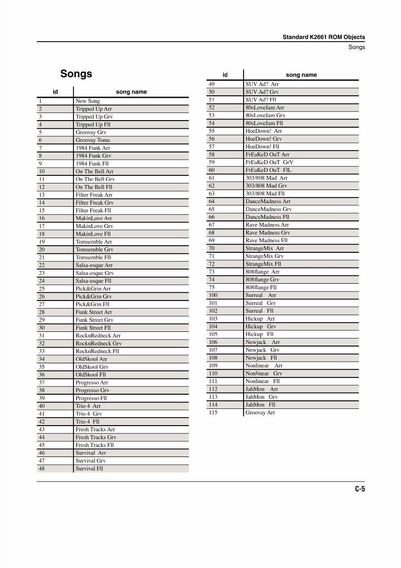
8/21/2019 MR_K2661
http://slidepdf.com/reader/full/mrk2661 397/499
Standard K2661 ROM Objects
Songs
C-5
Songs
id song name
1 New Song
2 Tripped Up Arr
3 Tripped Up Grv
4 Tripped Up Fll
5 Groovay Grv
6 Groovay Toms
7 1984 Funk Arr
8 1984 Funk Grv
9 1984 Funk Fll
10 On The Bell Arr
11 On The Bell Grv
12 On The Bell Fll
13 Filter Freak Arr
14 Filter Freak Grv
15 Filter Freak Fll
16 MakinLove Arr
17 MakinLove Grv
18 MakinLove Fll
19 Tomsemble Arr
20 Tomsemble Grv
21 Tomsemble Fll
22 Salsa-esque Arr
23 Salsa-esque Grv
24 Salsa-esque Fll
25 Pick&Grin Arr
26 Pick&Grin Grv27 Pick&Grin Fll
28 Funk Street Arr
29 Funk Street Grv
30 Funk Street Fll
31 RocknRedneck Arr
32 RocknRedneck Grv
33 RocknRedneck Fll
34 OldSkool Arr
35 OldSkool Grv
36 OldSkool Fll
37 Progresso Arr
38 Progresso Grv
39 Progresso Fll40 Trio 4 Arr
41 Trio 4 Grv
42 Trio 4 Fll
43 Fresh Tracks Arr
44 Fresh Tracks Grv
45 Fresh Tracks Fll
46 Survival Arr
47 Survival Grv
48 Survival Fll
49 SUV Ad? Arr
50 SUV Ad? Grv
51 SUV Ad? Fll52 80sLoveJam Arr
53 80sLoveJam Grv
54 80sLoveJam Fll
55 HoeDown! Arr
56 HoeDown! Grv
57 HoeDown! Fll
58 FrEaKeD OuT Arr
59 FrEaKeD OuT GrV
60 FrEaKeD OuT FlL
61 303/808 Mad Arr
62 303/808 Mad Grv
63 303/808 Mad Fll
64 DanceMadness Arr
65 DanceMadness Grv
66 DanceMadness Fll
67 Rave Madness Arr
68 Rave Madness Grv
69 Rave Madness Fll
70 StrangeMix Arr
71 StrangeMix Grv
72 StrangeMix Fll
73 808flange Arr
74 808flange Grv
75 808flange Fll
100 Surreal Arr
101 Surreal Grv
102 Surreal Fll
103 Hickup Arr
104 Hickup Grv
105 Hickup Fll
106 Newjack Arr
107 Newjack Grv
108 Newjack Fll
109 Nonlinear Arr
110 Nonlinear Grv
111 Nonlinear Fll
112 JahMon Arr
113 JahMon Grv114 JahMon Fll
115 Groovay Arr
id song name
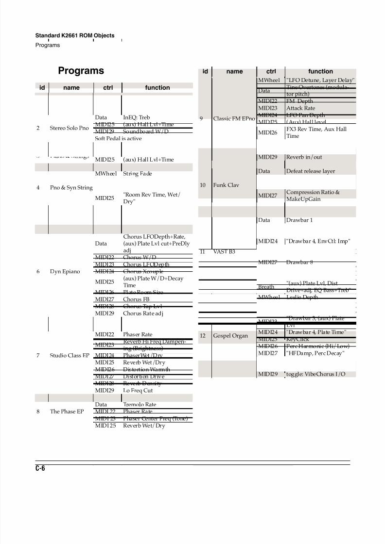
8/21/2019 MR_K2661
http://slidepdf.com/reader/full/mrk2661 398/499
C-6
Standard K2661 ROM Objects
Programs
Programs
id name ctrl function
1 Concert PianoMIDI25 (aux) Hall Lvl+TimeMIDI29 Soundboard W/DSoft Pedal is active
2 Stereo Solo Pno
Data InEQ: TrebMIDI25 (aux) Hall Lvl+TimeMIDI29 Soundboard W/DSoft Pedal is active
3 Piano & Strings
MWheel String Balance - softerData String Balance - louderMIDI25 (aux) Hall Lvl+TimeSoft Pedal is active
4 Pno & Syn String
MWheel String FadeData String Swell
MIDI23 SRS SpaceMIDI25
"Room Rev Time, Wet/Dry"
5 Rock GrandMIDI25 (aux) Hall Lvl+TimeMIDI29 Soundboard W/DSoft Pedal is active
6 Dyn Epiano
MWheel Tremolo/ Vibrato
DataChorus LFODepth+Rate,(aux) Plate Lvl cut+PreDlyadj
MIDI22 Chorus W/DMIDI23 Chorus LFODepthMIDI24 Chorus Xcouple
MIDI25(aux) Plate W/D+Decay
TimeMIDI26 Plate Room SizeMIDI27 Chorus FBMIDI28 Chorus Tap LvlMIDI29 Chorus Rate adj
7 Studio Class EP
MWheel Stereo TremoloData Tremolo RateMIDI22 Phaser Rate
MIDI23Reverb Hi Freq Dampen-ing (Brightness)
MIDI24 PhaserWet/DryMIDI25 Reverb Wet/DryMIDI26 Distortion WarmthMIDI27 Distortion Drive
MIDI28 Reverb DensityMIDI29 Lo Freq Cut
8 The Phase EP
MWheel Enables Stereo TremoloData Tremolo RateMIDI 22 Phaser RateMIDI 23 Phaser Center Freq (Tone)MIDI 25 Reverb Wet/Dry
9 Classic FM EPno
MWheel "LFO Detune, Layer Delay"
DataTine Overtones (modula-
tor pitch)MIDI22 FM DepthMIDI23 Attack RateMIDI24 LFO Pan DepthMIDI25 (Aux) Hall level
MIDI26FX3 Rev Time, Aux HallTime
MIDI27 Chorus Feedback MIDI28 Reverb PredelayMIDI29 Reverb in/out
10 Funk Clav
MWheel VibratoData Defeat release layerMIDI25 (Aux) Hall LevelMIDI26 (Aux) HF Damping
MIDI27 Compression Ratio &MakeUpGain
MIDI28 (Aux) Pre-Delay
11 VAST B3
MWheel Leslie DepthData Drawbar 1MIDI22 Drawbar 2MIDI23 Drawbar 3MIDI24 "Drawbar 4, EnvCtl: Imp"MIDI25 "Drawbar 5,6"MIDI26 Drawbar 7MIDI27 Drawbar 8MIDI28 Drawbar 9MIDI29 toggle: Vib/Chorus I/O
Breath "(aux) Plate Lvl, DistDrive+adj, EQ Bass+Treb"
12 Gospel Organ
MWheel Leslie DepthData Drawbar 1MIDI22 Drawbar 2
MIDI23"Drawbar 3, (aux) PlateLvl"
MIDI24 "Drawbar 4, Plate Time"MIDI25 KeyClick MIDI26 Perc Harmonic (Hi/Low)MIDI27 "HFDamp, Perc Decay"
MIDI28Cabinet Dist Drive +Lopass adj
MIDI29 toggle: VibeChorus I/O
id name ctrl function
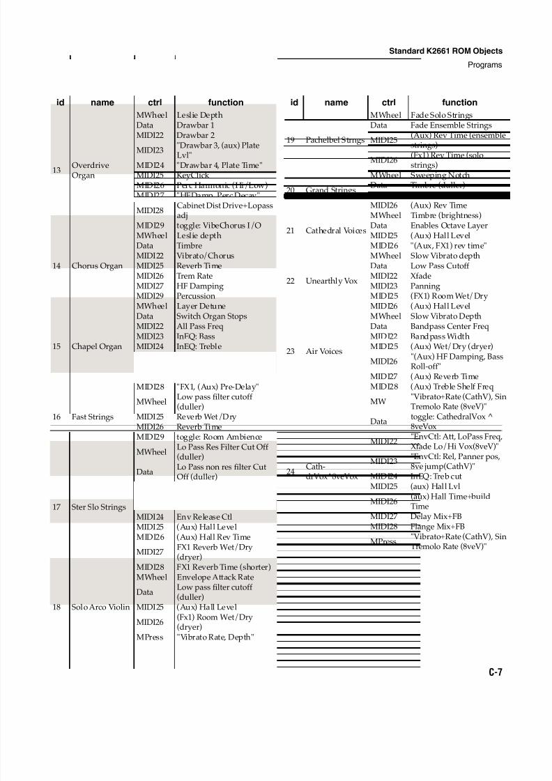
8/21/2019 MR_K2661
http://slidepdf.com/reader/full/mrk2661 399/499
Standard K2661 ROM Objects
Programs
C-7
13OverdriveOrgan
MWheel Leslie DepthData Drawbar 1
MIDI22 Drawbar 2MIDI23
"Drawbar 3, (aux) PlateLvl"
MIDI24 "Drawbar 4, Plate Time"MIDI25 KeyClick MIDI26 Perc Harmonic (Hi/Low)MIDI27 "HFDamp, Perc Decay"
MIDI28Cabinet Dist Drive+Lopassadj
MIDI29 toggle: VibeChorus I/O
14 Chorus Organ
MWheel Leslie depthData TimbreMIDI22 Vibrato/ChorusMIDI25 Reverb Time
MIDI26 Trem RateMIDI27 HF DampingMIDI29 Percussion
15 Chapel Organ
MWheel Layer DetuneData Switch Organ StopsMIDI22 All Pass FreqMIDI23 InEQ: BassMIDI24 InEQ: TrebleMIDI25 (Aux) Hall LevelMIDI26 "FX1, (Aux) Size Scale"MIDI27 "FX1, (Aux) HF Damping"MIDI28 "FX1, (Aux) Pre-Delay"
16 Fast Strings
MWheelLow pass filter cutoff
(duller)MIDI25 Reverb Wet/DryMIDI26 Reverb TimeMIDI29 toggle: Room Ambience
17 Ster Slo Strings
MWheelLo Pass Res Filter Cut Off(duller)
DataLo Pass non res filter CutOff (duller)
MIDI22Lo Pass Res Filter Cut Off(Brighter)
MIDI23 Env Atk CtlMIDI24 Env Release CtlMIDI25 (Aux) Hall LevelMIDI26 (Aux) Hall Rev Time
MIDI27 FX1 Reverb Wet/Dry(dryer)
MIDI28 FX1 Reverb Time (shorter)
18 Solo Arco Violin
MWheel Envelope Attack Rate
DataLow pass filter cutoff(duller)
MIDI25 (Aux) Hall Level
MIDI26(Fx1) Room Wet/Dry(dryer)
MPress "Vibrato Rate, Depth"
id name ctrl function
19 Pachelbel Strngs
MWheel Fade Solo StringsData Fade Ensemble Strings
MIDI25 (Aux) Rev Time (ensemblestrings)
MIDI26(Fx1) Rev Time (solostrings)
20 Grand Strings
MWheel Sweeping NotchData Timbre (duller)MIDI25 (Aux) Hall LevelMIDI26 (Aux) Rev Time
21 Cathedral Voices
MWheel Timbre (brightness)Data Enables Octave LayerMIDI25 (Aux) Hall LevelMIDI26 "(Aux, FX1) rev time"
22 Unearthly Vox
MWheel Slow Vibrato depthData Low Pass Cutoff
MIDI22 XfadeMIDI23 PanningMIDI25 (FX1) Room Wet/DryMIDI26 (Aux) Hall Level
23 Air Voices
MWheel Slow Vibrato DepthData Bandpass Center FreqMIDI22 Bandpass WidthMIDI25 (Aux) Wet/Dry (dryer)
MIDI26"(Aux) HF Damping, BassRoll-off"
MIDI27 (Aux) Reverb TimeMIDI28 (Aux) Treble Shelf Freq
24Cath-drVox^8veVox
MW"Vibrato+Rate (CathV), Sin
Tremolo Rate (8veV)"Data
toggle: CathedralVox ^8veVox
MIDI22"EnvCtl: Att, LoPass Freq,Xfade Lo/Hi Vox(8veV)"
MIDI23"EnvCtl: Rel, Panner pos,8ve jump(CathV)"
MIDI24 InEQ: Treb cutMIDI25 (aux) Hall Lvl
MIDI26(aux) Hall Time+buildTime
MIDI27 Delay Mix+FBMIDI28 Flange Mix+FB
MPress"Vibrato+Rate (CathV), Sin
Tremolo Rate (8veV)"
id name ctrl function
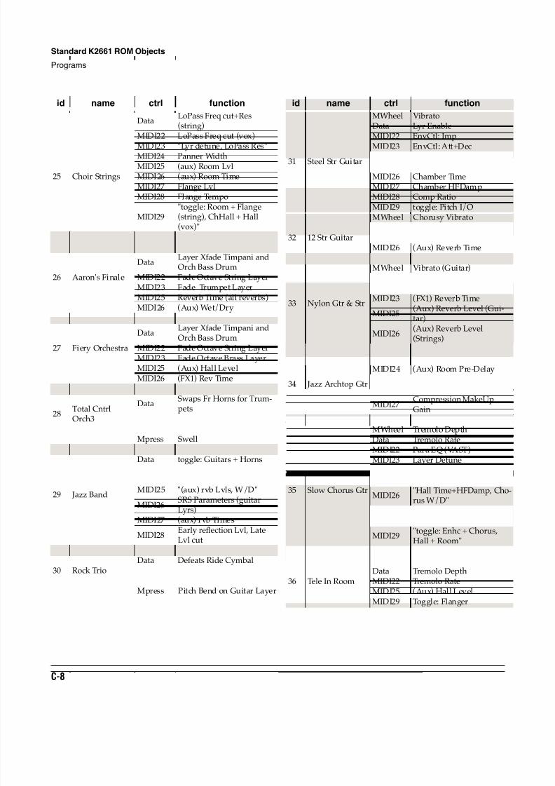
8/21/2019 MR_K2661
http://slidepdf.com/reader/full/mrk2661 400/499
C-8
Standard K2661 ROM Objects
Programs
25 Choir Strings
DataLoPass Freq cut+Res(string)
MIDI22 LoPass Freq cut (vox)MIDI23 "Lyr detune, LoPass Res"MIDI24 Panner WidthMIDI25 (aux) Room LvlMIDI26 (aux) Room TimeMIDI27 Flange LvlMIDI28 Flange Tempo
MIDI29"toggle: Room + Flange(string), ChHall + Hall(vox)"
Mpress InEQ Bass & Treble
26 Aaron's Finale
MWheel defeats vel. Crash
DataLayer Xfade Timpani andOrch Bass Drum
MIDI22 Fade Octave String LayerMIDI23 Fade Trumpet LayerMIDI25 Reverb Time (all reverbs)MIDI26 (Aux) Wet/Dry
27 Fiery Orchestra
MWheel defeats vel. Crash
DataLayer Xfade Timpani andOrch Bass Drum
MIDI22 Fade Octave String LayerMIDI23 Fade Octave Brass LayerMIDI25 (Aux) Hall LevelMIDI26 (FX1) Rev Time
28 Total CntrlOrch3
MWheel defeats vel. Crash
DataSwaps Fr Horns for Trum-
petsMIDI25 (Aux) Hall LevelMIDI26 Reverb Time (all verbs)Mpress Swell
29 Jazz Band
MW Tremolo (guitars)Data toggle: Guitars + HornsMIDI22 toggle: Band and DrumsMIDI23 Tremolo RateMIDI25 "(aux) rvb Lvls, W/D"
MIDI26SRS Parameters (guitarLyrs)
MIDI27 (aux) rvb Times
MIDI28Early reflection Lvl, LateLvl cut
30 Rock Trio
MW Leslie DepthData Defeats Ride CymbalMIDI22 Vibrato/ChorusMIDI23 Swap Guitar for OrganMpress Pitch Bend on Guitar Layer
id name ctrl function
31 Steel Str Guitar
MWheel VibratoData Lyr Enable
MIDI22 EnvCtl: ImpMIDI23 EnvCtl: Att+DecMIDI24 EnvCtl: RelMIDI25 (aux) Chamber W/DMIDI26 Chamber TimeMIDI27 Chamber HFDampMIDI28 Comp RatioMIDI29 toggle: Pitch I/O
32 12 Str Guitar
MWheel Chorusy VibratoData Exciter gainMIDI25 (Aux) Wet/DryMIDI26 (Aux) Reverb TimeMIDI27 (Aux) Compression Ratio
33 Nylon Gtr & Str
MWheel Vibrato (Guitar)
Data Fade StringsMIDI22 (FX1) Reverb Wet/DryMIDI23 (FX1) Reverb Time
MIDI25(Aux) Reverb Level (Gui-tar)
MIDI26(Aux) Reverb Level(Strings)
34 Jazz Archtop Gtr
MWheel VibratoData Defeats Release LayerMIDI24 (Aux) Room Pre-DelayMiidi25 (Aux) Room LevelMIDI26 (Aux) Rev Time
MIDI27Compression MakeUp
GainMIDI28 Compression Ratio
35 Slow Chorus Gtr
MWheel Tremolo DepthData Tremolo RateMIDI22 Para EQ (VAST)MIDI23 Layer DetuneMIDI24 Env Ctl (decay & release)MIDI25 (aux) Hall Lvl
MIDI26"Hall Time+HFDamp, Cho-rus W/D"
MIDI27 "Enhc Lo Mix, Chorus FB"MIDI28 Enhc Hi Mix+Drive
MIDI29"toggle: Enhc + Chorus,Hall + Room"
MPress Vibrato
36 Tele In Room
MWheel VibratoData Tremolo DepthMIDI22 Tremolo RateMIDI25 (Aux) Hall LevelMIDI29 Toggle: Flanger
id name ctrl function
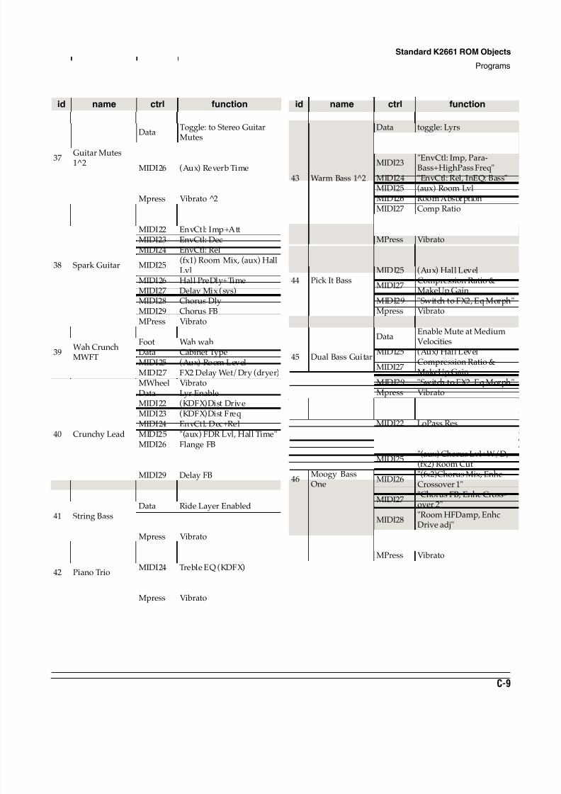
8/21/2019 MR_K2661
http://slidepdf.com/reader/full/mrk2661 401/499
Standard K2661 ROM Objects
Programs
C-9
37Guitar Mutes1^2
MWheel Vibrato
DataToggle: to Stereo Guitar
MutesMIDI22 Para EQ (VAST)MIDI25 (Aux) Reverb Wet/DryMIDI26 (Aux) Reverb TimeMIDI27 (Aux) HF DampingMIDI28 (Aux) Compression RatioMpress Vibrato 2
38 Spark Guitar
MWheel VibratoData HFStim adjMIDI22 EnvCtl: Imp+AttMIDI23 EnvCtl: DecMIDI24 EnvCtl: Rel
MIDI25(fx1) Room Mix, (aux) HallLvl
MIDI26 Hall PreDly+TimeMIDI27 Delay Mix (sys)MIDI28 Chorus DlyMIDI29 Chorus FBMPress Vibrato
39Wah CrunchMWFT
MWheel Wah wahFoot Wah wahData Cabinet TypeMIDI25 (Aux) Room LevelMIDI27 FX2 Delay Wet/Dry (dryer)
40 Crunchy Lead
MWheel VibratoData Lyr EnableMIDI22 (KDFX)Dist Drive
MIDI23 (KDFX)Dist FreqMIDI24 EnvCtl: Dec+RelMIDI25 "(aux) FDR Lvl, Hall Time"MIDI26 Flange FBMIDI27 Flange TempoMIDI28 Delay MixMIDI29 Delay FBMPress Lyr Balance
41 String Bass
MWheel VibratoData Ride Layer EnabledMIDI25 (FX1) Room Wet/DryMIDI26 (Aux) Hall LevelMpress Vibrato
42 Piano Trio
MWheel Vibrato
Data Ride Cymbal FadeMIDI24 Treble EQ (KDFX)
MIDI25"(Aux) Hall Level, (FX1)wet/dry (dryer)"
Mpress Vibrato
id name ctrl function
43 Warm Bass 1^2
MWheel VibratoData toggle: Lyrs
MIDI22 "LoPass adj, Shaper amt,EnvCtl: Imp+Att"
MIDI23"EnvCtl: Imp, Para-Bass+HighPass Freq"
MIDI24 "EnvCtl: Rel, InEQ: Bass"MIDI25 (aux) Room LvlMIDI26 Room AbsorptionMIDI27 Comp RatioMIDI28 Comp: Att+Rel TimeMIDI29 add EQ MorphMPress Vibrato
44 Pick It Bass
MWheel VibratoData "Shaper, Para Treble boost"MIDI25 (Aux) Hall Level
MIDI27 Compression Ratio &MakeUp Gain
MIDI29 "Switch to FX2, Eq Morph"Mpress Vibrato
45 Dual Bass Guitar
MWheel Vibrato
DataEnable Mute at MediumVelocities
MIDI25 (Aux) Hall Level
MIDI27Compression Ratio &MakeUp Gain
MIDI29 "Switch to FX2, Eq Morph"Mpress Vibrato
46Moogy BassOne
MWheel Vibrato
Data LoPass FreqMIDI22 LoPass ResMIDI23 Env Ctl: Attack & ImpactMIDI24 Env Ctl: Release
MIDI25"(aux) Chorus Lvl+W/D,(fx2) Room Cut"
MIDI26"(fx2)Chorus Mix, EnhcCrossover 1"
MIDI27"Chorus FB, Enhc Cross-over 2"
MIDI28"Room HFDamp, EnhcDrive adj"
MIDI29toggle: ChorVerb + Enhc;Enhc Lo+Mid+Hi Drive
MPress Vibrato
id name ctrl function
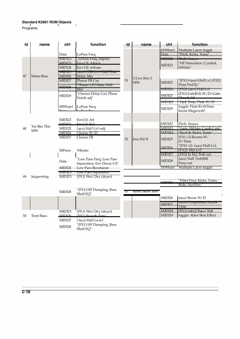
8/21/2019 MR_K2661
http://slidepdf.com/reader/full/mrk2661 402/499
C-10
Standard K2661 ROM Objects
Programs
47 Mono Bass
MW VibratoData LoPass Freq
MIDI22 "LoPass Freq, Impact"MIDI23 Env Ctl: Attack MIDI24 Env Ctl: releaseMIDI25 (aux) CDR Lvl+Hall TimeMIDI26 Delay MixMIDI27 Phaser FB Cut
MIDI28"Phaser LFO Rate, HallMix"
MIDI29"Chorus-Delay Cut, PhaseNotch adj"
MPress Vibrato
48Tee Bee ThisMW
MWheel LoPass FreqData LoPass ResMIDI22 EnvCtl: Imp
MIDI23 EnvCtl: AttMIDI24 EnvCtl: RelMIDI25 (aux) Hall Lvl+adjMIDI26 Chorus W/DMIDI27 Chorus FBMIDI28 Chorus Tap PanMIDI29 add EnhcMPress Vibrato
49 Sequenting
MWheel Vibrato
Data"Low Pass Freq, Low PassSeparation, Env Decay Ctl"
MIDI22 Low Pass ResonanceMIDI23 Low Pass Separation
MIDI25 (FX1) Wet/Dry (dryer)MIDI26 (FX1) Reverb TimeMIDI27 (Aux) Hall Level
MIDI28"(FX1) HF Damping, BassShelf EQ"
MPress Vibrato
50 Trent Bass
MWheel LPGate FreqData "Saw+Shp Pitch, Atk Ctl"MIDI25 (FX1) Wet/Dry (dryer)MIDI26 (FX1) Reverb TimeMIDI27 (Aux) Hall Level
MIDI28"(FX1) HF Damping, BassShelf EQ"
id name ctrl function
512 Live Kits 2MW
MWheel Multiple Layer toggleData "Pitch: Kicks, Toms"
MIDI22 Pitch: SnaresMIDI23
"HF Stimulator: Cymbal,HiHats"
MIDI24"EnvCtl: Kicks, Snares,Toms, Cymbal"
MIDI25"(FX1)-(aux) Hall Lvl, (FX2)Plate PreDly"
MIDI26 (FX2)-(aux) Hall Lvl
MIDI27(FX1) GateRvb W/D+GateThreshold
MIDI28 "Hall Time, Plate W/D"
MIDI29toggle: Plate RvrbTime
boost-Megaverb!
52 Jazz Kit II
MWheel Pitch: AuxPerc
Data "Pitch: Kicks, Toms"MIDI22 Pitch: SnaresMIDI23 "Gain: HiHats, Crash Cym"MIDI24 "EnvClt: Kicks, Toms"
MIDI25(FX1+2) Rooms W/D+Time
MIDI26"(FX1+2)- (aux) Hall Lvl,(FX2)- Mix Lvl"
MIDI27 (FX2) In EQ: Treb cut
MIDI28(aux) Hall TrebShlfFreq+cut
53 Retro Skins MW
MWheel Multiple Layer toggleData Pitch: KicksMIDI22 Pitch: Snares
MIDI23"Filter Freq: Kicks, Toms,Ride, AuxPerc "
MIDI24 EnvCtl: Kicks+SnaresMIDI25 (FX1+2) Rooms W/DMIDI26 (aux) Room W/D
MIDI27(aux) Compressor AttackTime
MIDI28 (FX1) InEQ: Bass+TrebMIDI29 toggle: Alien Skin Effect
id name ctrl function
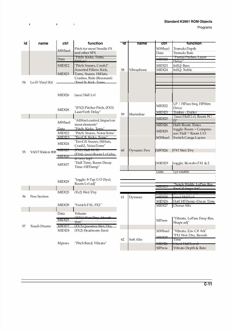
8/21/2019 MR_K2661
http://slidepdf.com/reader/full/mrk2661 403/499
Standard K2661 ROM Objects
Programs
C-11
54 Lo-Fi Vinyl Kit
MWheelPitch for most Needle FXand other SFX
Data "Pitch: Kicks, Toms,HiHats"
MIDI22 "Pitch: Snares, Crash1"
MIDI23Assorted Filters: Kick,Toms, Snares, HiHats,Crashes, Ride (Resonant)
MIDI24"EnvClt: Kick, Toms,Snares"
MIDI25 (FX1) Booth W/DMIDI26 (aux) Hall Lvl
MIDI27"(FX2) Pitcher W/D, (FX3)LaserVerb W/D"
MIDI28"(FX2) Pitcher Pitch, (FX3)LaserVerb Delay"
MIDI29 toggle: Pitcher + LaserVerb
55 VAST Sliders 808
MWheel"AltStart control, Impact onmost elements"
Data "Pitch: Kicks, Toms"MIDI22 "Pitch: Snares, NoizeToms"MIDI23 "EnvCtl: Kicks, Toms"
MIDI24"EnvCtl: Snares, HiHats,Crash2, NoizeToms"
MIDI25 (FX1) Hall W/D
MIDI26(FX4)- (aux) Room Lvl (dryat very top)
MIDI27"Hall Time, Room DecayTime+HFDamp"
MIDI28"(FX2) Flange W/D+FB,(FX3) 8-Tap W/D"
MIDI29"toggle: 8-Tap I/O (Sys),Room Lvl adj"
56 Perc Section
MIDI22 "(FX1, FX3) Wet/Dry"MIDI23 (Fx2) Wet/DryMIDI24 "Reverb Time FX1, FX2"MIDI25 (Aux) Reverb TimeMIDI29 "Switch FX1, FX2"
57 Touch Drums
MWheel VibratoData Volume
MIDI25"(FX1) Wet/Dry, Absorb-tion"
MIDI27 (FX2) Quantize Wet/Dry
MIDI28 (FX2) Headroom (less)MIDI29
"Switch to FX bus 2, Quan-tize/Flange"
Mpress "Pitch Bend, Vibrato"
id name ctrl function
58 Vibraphone
MWheel Tremolo DepthData Tremolo Rate
MIDI22 "Partial Pitches, LayerDelay"
MIDI23 InEQ: BassMIDI24 InEQ: TrebleMIDI25 (Aux) Reverb Level
MIDI26"(Aux) Reverb Time, TrebleShelf Gain"
MIDI27 Chorus MixMIDI28 Chorus Depth
59 Marimbae
MWheel "EnvCtl: Rel, Tremolo"Data Fade in Percussive Layer
MIDI22LP / HPass freq, HFStimDrive
MIDI23 Timbre - Duller
MIDI25 "(aux) Hall Lvl, Room W/D"
MIDI26 Hall+Room Times
MIDI29toggle: Room + Compres-sor/Hall ^ Room I/O
60 Dynamic Perc
MWheel Switch Conga LayersData Conga Pitch when MW upMIDI25 "FX1,3 Wet/Dry"MIDI26 FX2 Wet/DryMIDI27 "FX1,2 Rev Times"MIDI28 "(Aux) Wet/Dry, Rev Time"MIDI29 toggle; Reverbs FX1 & 2
61 Dynasax
MWheel "Vibrato, LoPass Freq"
Data Lyr enableMIDI22
"Lyr AltCtl, LoPass Freq,Notch Freq, ParaTreb Freq"
MIDI23"Notch Width, LoPass Res,EnvCtl: Imp+Att"
MIDI24 EnvCtl: Dec+RelMIDI25 (aux) Hall LvlMIDI26 Hall HFDamp+Decay TimeMIDI27 Chorus MixMIDI28 Delay (sys) MixMIDI29 Hall PreDly + room size adj
MPress"Vibrato, LoPass Freq+Res,Shape adj"
ChanSt "Lyr AltCtl, EnvCtl: Rel"
62 Soft Alto
MWheel "Vibrato, Env Ctl Atk"MIDI25
"FX1 Wet/Dry, ReverbTime"
MIDI26 (Aux) Hall LevelMPress Vibrato Depth & Rate
id name ctrl function
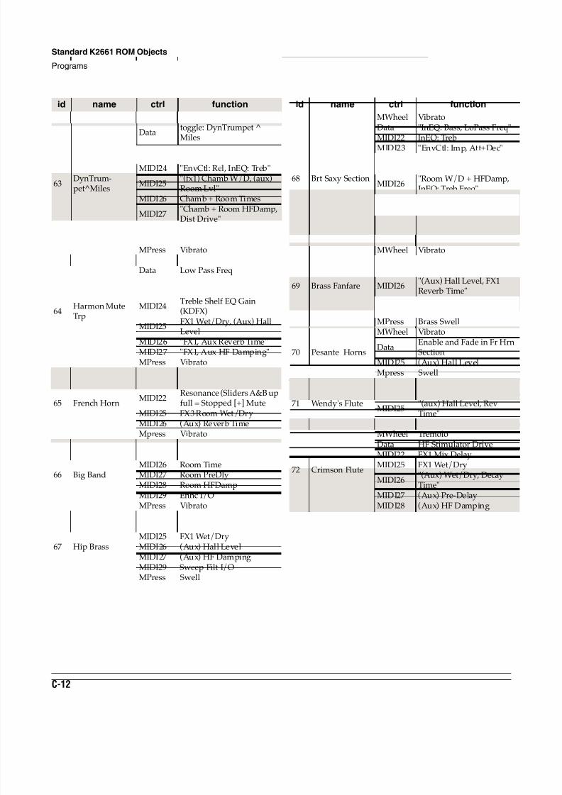
8/21/2019 MR_K2661
http://slidepdf.com/reader/full/mrk2661 404/499
C-12
Standard K2661 ROM Objects
Programs
63DynTrum-pet^Miles
MWheel "swell, Vibrato"
Datatoggle: DynTrumpet ^
MilesMIDI22 LoPass Freq+ResMIDI23 "EnvCtl: Imp, InEQ: Bass"MIDI24 "EnvCtl: Rel, InEQ: Treb"
MIDI25"(fx1) Chamb W/D, (aux)Room Lvl"
MIDI26 Chamb + Room Times
MIDI27"Chamb + Room HFDamp,Dist Drive"
MIDI28 Dist LoPass FreqMIDI29 toggle: Chamb + DistMPress Vibrato
64Harmon MuteTrp
MWheel VibratoData Low Pass Freq
MIDI22 Bandpass Ctr FreqMIDI23 Bass Shelf EQ Gain (KDFX)
MIDI24Treble Shelf EQ Gain(KDFX)
MIDI25FX1 Wet/Dry, (Aux) HallLevel
MIDI26 "FX1, Aux Reverb Time"MIDI27 "FX1, Aux HF Damping"MPress Vibrato
65 French Horn
MWheel SwellData Low Pass Freq
MIDI22Resonance (Sliders A&B upfull = Stopped [+] Mute
MIDI25 FX3 Room Wet/DryMIDI26 (Aux) Reverb TimeMpress Vibrato
66 Big Band
MWheel LoPass adjMIDI25 (aux) Room W/DMIDI26 Room TimeMIDI27 Room PreDlyMIDI28 Room HFDampMIDI29 Enhc I/OMPress Vibrato
67 Hip Brass
MWheel VibratoData Low Pass FreqMIDI25 FX1 Wet/DryMIDI26 (Aux) Hall Level
MIDI27 (Aux) HF DampingMIDI29 Sweep Filt I/OMPress Swell
id name ctrl function
68 Brt Saxy Section
MWheel VibratoData "InEQ: Bass, LoPass Freq"
MIDI22 InEQ: TrebMIDI23 "EnvCtl: Imp, Att+Dec"MIDI24 EnvCtl: RelMIDI25 (aux) Room Lvl
MIDI26"Room W/D + HFDamp,InEQ: Treb Freq"
MIDI27 Dist tube DriveMIDI28 Dist Warmth+Tone
MIDI29"toggle: Dist+EQ I/O,Room type"
MPress Vibrato
69 Brass Fanfare
MWheel VibratoData Fade in French Horn layerMIDI25 FX1 Room Wet/Dry
MIDI26 "(Aux) Hall Level, FX1Reverb Time"
MIDI27 (Aux) HF DampingMIDI29 toggle: HallMPress Brass Swell
70 Pesante Horns
MWheel Vibrato
DataEnable and Fade in Fr HrnSection
MIDI25 (Aux) Hall LevelMpress Swell
71 Wendy's Flute
MWheel Low Pass FreqData toggle: Flute Variation
MIDI25"(aux) Hall Level, Rev
Time"MIDI29 toggle: Hall
72 Crimson Flute
MWheel TremoloData HF Stimulator DriveMIDI22 FX1 Mix DelayMIDI25 FX1 Wet/Dry
MIDI26"(Aux) Wet/Dry, DecayTime"
MIDI27 (Aux) Pre-DelayMIDI28 (Aux) HF Damping
id name ctrl function
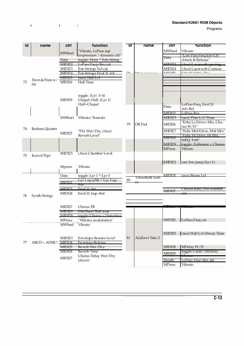
8/21/2019 MR_K2661
http://slidepdf.com/reader/full/mrk2661 405/499
Standard K2661 ROM Objects
Programs
C-13
73Horn & Flute w/Str
MWheel"Vibrato, LoPass sep(expression / dynamic ctl)"
Data toggle: Horn Solo StringMIDI22 LoPass Freq+Res cutMIDI23 Ens Strings Vol cutMIDI24 Ens Strings EnvCtl: AttMIDI25 (aux) Hall LvlMIDI26 Hall TimeMIDI27 (FX1) Chapel W/DMIDI28 Chapel Time
MIDI29toggle: (Lyr 3+4)Chapel+Hall, (Lyr 1)Hall+Chapel
MPress Ens Strings VibratoSostPd toggle: Solo Strg I/O
74 Brahms Quintet
MWheel Vibrato/Tremolo
Data Fade out Pizz BassesMIDI22 Fade out Brass
MIDI25"FX1 Wet/Dry, (Aux)Reverb Level"
MIDI26 (Aux) Reverb Time
75 Kurz'd Pipe
MWheel VibratoData Fade Chiff LayerMIDI25 (Aux) Chamber LevelMIDI26 (Aux) Reverb TimeMIDI29 toggle: PitcherMpress Vibrato
76 Synth Strings
MWheel "Vibrato, modulation"Data toggle: Lyr 1 Lyr 3
MIDI22 Lyr 1 up p5th ^ Lyr 3 up8veMIDI23 EnvCtl: AttMIDI24 EnvCtl: Imp+RelMIDI25 (aux) Plate LvlMIDI26 "Chorus W/D, Dist Drive"MIDI27 Chorus FBMIDI28 Dist Bass+Treb toneMIDI29 toggle: Chorus + DistortionMPress "Vibrato, modulation"
77 ABCD = ADSR !
MWheel VibratoData Filter Envelope Attack MIDI22 Filter Envelope DecayMIDI23 Envelope Sustain Level
MIDI24 Envelope ReleaseMIDI25 Reverb Wet/DryMIDI26 Reverb Time
MIDI27Chorus Delay Wet/Dry(dryer)
id name ctrl function
78 Memorymoog
MWheel Vibrato
Data"Low Pass Freq,Env Ctl
Attack & Release"MIDI23 (Aux) Lazerverb spacingMIDI24 (Aux) Lazerverb ContourMIDI25 FX1 Hall Wet/DryMIDI26 FX1 Reverb Time
MIDI27"(Aux) Lazerverb Level,Feedback level"
MIDI28 (Aux) Dly CoarseMpress Vibrato
79 OB Pad
MWheel Vibrato
DataLoPass Freq, EnvCtl:Att+Rel
MIDI22 LoPass ResMIDI25 (aux) Plate Lvl+Time
MIDI26 "Enhc Lo Drive+Mix, Cho-rus W/D "
MIDI27 "Enhc Mid Drive, Mid Mix"
MIDI28"Enhc Hi Drive, Hi Mix,InEQ: Treb"
MIDI29 toggle: Enhancer + ChorusMPress Vibrato
80
TeknoBallCrush
er
MWheel VibratoData "EnvCtl: Att, Notch Freq"MIDI22 saw 8ve jump (Lyr 1)MIDI23 EnvCtl: ImpactMIDI24 EnvCtl: RelMIDI25 (aux) Room Lvl
MIDI26 Chorus W/D; Dist Drivecut
MIDI27Chorus Rate; Dist warmthcut
MIDI28 Chorus FB; Dist cab LoPassMIDI29 toggle: Chorus + DistortionMPress Vibrato
81 AlaZawi Take 2
MWheel VibratoData LoPass Freq+ResMIDI22 LoPass Freq cutMIDI23 InEQ: BassMIDI24 InEQ: TrebMIDI25 (aux) Hall Lvl+Decay TimeMIDI26 Hall PreDly+HFDamp
MIDI27 Chorus W/D+PanMIDI28 MDelay W/D
MIDI29toggle: Clean +MDelay-Chorus
Breath LoPass Freq+Res adjMPress Vibrato
id name ctrl function
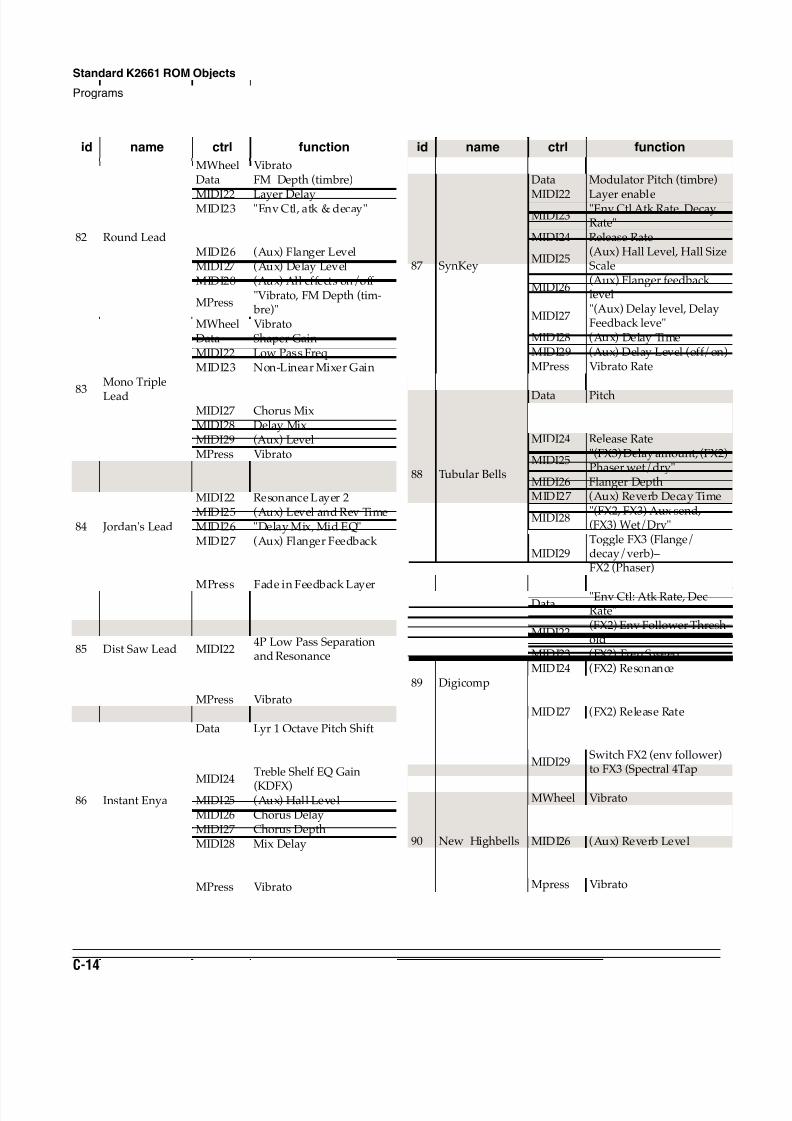
8/21/2019 MR_K2661
http://slidepdf.com/reader/full/mrk2661 406/499
C-14
Standard K2661 ROM Objects
Programs
82 Round Lead
MWheel VibratoData FM Depth (timbre)
MIDI22 Layer DelayMIDI23 "Env Ctl, atk & decay"MIDI24 Release RateMIDI25 (Aux) Hall LevelMIDI26 (Aux) Flanger LevelMIDI27 (Aux) Delay LevelMIDI28 (Aux) All effects on/off
MPress"Vibrato, FM Depth (tim-
bre)"
83
Mono Triple
Lead
MWheel VibratoData Shaper GainMIDI22 Low Pass FreqMIDI23 Non-Linear Mixer GainMIDI25 FX3 Wet/Dry
MIDI26 FX3 and Aux Rev TimesMIDI27 Chorus MixMIDI28 Delay MixMIDI29 (Aux) LevelMPress Vibrato
84 Jordan's Lead
MWheel VibratoData Low Pass Freq & ResMIDI22 Resonance Layer 2MIDI25 (Aux) Level and Rev TimeMIDI26 "Delay Mix, Mid EQ"MIDI27 (Aux) Flanger Feedback MIDI28 (Aux) Flanger TempoMIDI29 Distortion Drive
MPress Fade in Feedback Layer
85 Dist Saw Lead
MWheelXfade Octave Feedback,Vibrato
Data Low Pass Freq
MIDI224P Low Pass Separationand Resonance
MIDI25 (Aux) Hall LevelMIDI26 (Aux) Wet/DryMPress Vibrato
86 Instant Enya
MWheel VibratoData Lyr 1 Octave Pitch ShiftMIDI22 Lyr 2 Low Pass FreqMIDI23 Bass Shelf EQ Gain (KDFX)
MIDI24
Treble Shelf EQ Gain
(KDFX)MIDI25 (Aux) Hall LevelMIDI26 Chorus DelayMIDI27 Chorus DepthMIDI28 Mix Delay
MIDI29(Aux) Pre-Delay, DecayTime
MPress Vibrato
id name ctrl function
87 SynKey
MWheel VibratoData Modulator Pitch (timbre)
MIDI22 Layer enableMIDI23
"Env Ctl Atk Rate, DecayRate"
MIDI24 Release Rate
MIDI25(Aux) Hall Level, Hall SizeScale
MIDI26(Aux) Flanger feedbacklevel
MIDI27"(Aux) Delay level, DelayFeedback leve"
MIDI28 (Aux) Delay TimeMIDI29 (Aux) Delay Level (off/on)MPress Vibrato Rate
88 Tubular Bells
MWheel Tremolo
Data PitchMIDI22 Modulator PitchesMIDI23 Attack RateMIDI24 Release Rate
MIDI25"(FX3) Delay amount, (FX2)Phaser wet/dry"
MIDI26 Flanger DepthMIDI27 (Aux) Reverb Decay Time
MIDI28"(FX2, FX3) Aux send,(FX3) Wet/Dry"
MIDI29Toggle FX3 (Flange/decay/verb)–FX2 (Phaser)
89 Digicomp
MWheel Vibrato
Data"Env Ctl: Atk Rate, DecRate"
MIDI22(FX2) Env Follower Thresh-old
MIDI23 (FX2) Freq SweepMIDI24 (FX2) ResonanceMIDI25 (FX2) Filter TypeMIDI26 (FX2) Minimum FreqMIDI27 (FX2) Release Rate
MIDI28"(FX3) Feedback Level, LFDamping"
MIDI29Switch FX2 (env follower)to FX3 (Spectral 4Tap
Mpress Vibrato
90 New Highbells
MWheel VibratoData Pitch (sine+)MIDI25 "(FX1) Wet/Dry, Rev Time"MIDI26 (Aux) Reverb Level
MIDI29toggle: FX1 (Plate) - FX2(Flange)
Mpress Vibrato
id name ctrl function
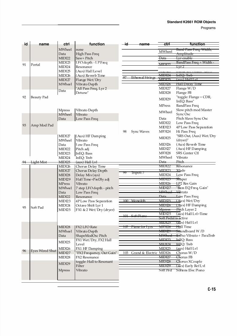
8/21/2019 MR_K2661
http://slidepdf.com/reader/full/mrk2661 407/499
Standard K2661 ROM Objects
Programs
C-15
91 Portal
MWheel noneData High Pass Freq
MIDI22 Saw+ PitchMIDI23 LFO depth - LP FreqMIDI24 ResonanceMIDI25 (Aux) Hall LevelMIDI26 (Aux) Reverb TimeMIDI27 Flange Wet/Dry
92 Beauty Pad
MWheel Vibrato Depth
Data"All Pass Freq, Lyr 2Detune"
MIDI22 Lyr 3 Pan PositionMIDI25 (Aux) Wet/Dry (dryer)MIDI26 (Aux) Reverb Time (less)Mpress Vibrato Depth
93 Amp Mod Pad
MWheel Vibrato
Data Low Pass Freq
MIDI25(Aux) Hall Wet/Dry(dryer)
MIDI26 (Aux) Reverb TimeMIDI27 (Aux) HF Damping
94 Light Mist
MWheel VibratoData Low Pass FreqMIDI22 Pitch adjMIDI23 InEQ: BassMIDI24 InEQ: TrebMIDI25 (aux) Hall LvlMIDI26 Chorus Delay TimeMIDI27 Chorus Delay Depth
MIDI28 Delay Mix (sys)MIDI29 Hall Time+PreDly adjMPress Vibrato
95 Soft Pad
MWheel 7 step LFO depth - pitchData Low Pass FreqMIDI22 ResonanceMIDI23 4P Low Pass SeparationMIDI24 Octave Shift Lyr 1MIDI25 FX1 & 2 Wet/Dry (dryer)
MIDI26FX2 Chorus FeedbackLevel
MIDI27 FX2 LFO DepthMIDI28 FX2 LFO Rate
96 Eyes Wired Shut
MWheel Vibrato Depth
Data ShapeModOsc Pitch
MIDI25FX1 Wet/Dry, FX2 HallLevel
MIDI26 FX1 HF DampingMIDI27 "FX2 Frequency, Out Gain"MIDI28 FX2 Resonance
MIDI29toggle: Hall to ResonantFilter
Mpress Vibrato
id name ctrl function
97 Ethereal Strings
MWheelBand Pass Freq, Width,Amplitude
Data Lyr enableMIDI22
BandPass Freq + Width -Lyr 2
MIDI23 BandPass Width - Lyr 3MIDI24 InEQ: TrebMIDI25 (aux) Hall LvlMIDI26 Hall Decay TimeMIDI27 Flange W/DMIDI28 Flange FB
MIDI29"toggle: Flange + CDR,InEQ: Bass"
MPress BandPass Freq
98 Sync Waves
MWheelSlow pitch mod MasterSync Osc
Data Pitch Slave Sync OscMIDI22 Low Pass FreqMIDI23 4P Low Pass SeparationMIDI24 Hi Pass Freq
MIDI25"SRS Out, (Aux) Wet/Dry(dryer)"
MIDI26 (Aux) Reverb TimeMIDI27 (Aux) HF DampingMIDI28 SRS Center Ctl
99 Tripoli 2
MWheel VibratoData PitchMIDI22 ResonanceMIDI23 Xfade
MIDI24 Low Pass FreqMIDI25 ShaperMIDI26 LP2 Res GainMIDI27 "Bass EQ Freq, Gain"
100 Monolith
MWheel VibratoData Low Pass FreqMIDI25 (Aux) Wet/DryMIDI26 (Aux) HF DampingMpress Pitch Layer 2
101 Soft PianoMIDI25 (aux) Hall Lvl+TimeSoft Pedal is active
102 Piano for LyrsMIDI25 (aux) Hall LvlMIDI26 Hall TimeMIDI29 Soundboard W/D
103 Grand & Electric
MWheel E Pno Vibrato + ParaTrebMIDI23 InEQ: BassMIDI24 InEQ: TrebMIDI25 (aux) Hall LvlMIDI26 Chorus W/DMIDI27 Chorus FBMIDI28 Chorus XCoupleMIDI29 (aux) Early Ref LvlSoft Ped Softens Elec Piano
id name ctrl function
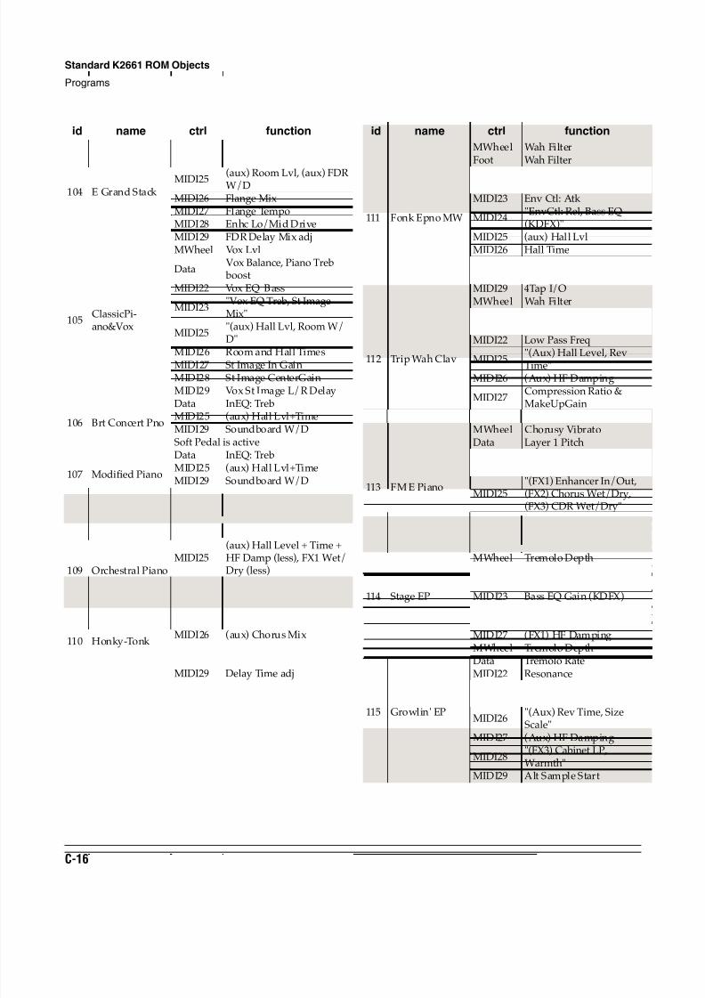
8/21/2019 MR_K2661
http://slidepdf.com/reader/full/mrk2661 408/499
C-16
Standard K2661 ROM Objects
Programs
104 E Grand Stack
MWheel String LvlData InEQ: Treb boost
MIDI25 (aux) Room Lvl, (aux) FDRW/D
MIDI26 Flange MixMIDI27 Flange TempoMIDI28 Enhc Lo/Mid DriveMIDI29 FDR Delay Mix adj
105ClassicPi-ano&Vox
MWheel Vox Lvl
DataVox Balance, Piano Treb
boostMIDI22 Vox EQ Bass
MIDI23"Vox EQ Treb, St ImageMix"
MIDI25"(aux) Hall Lvl, Room W/D"
MIDI26 Room and Hall TimesMIDI27 St Image In GainMIDI28 St Image CenterGainMIDI29 Vox St Image L/R Delay
106 Brt Concert Pno
Data InEQ: TrebMIDI25 (aux) Hall Lvl+TimeMIDI29 Soundboard W/DSoft Pedal is active
107 Modified Piano
Data InEQ: TrebMIDI25 (aux) Hall Lvl+TimeMIDI29 Soundboard W/DSoft Pedal is active
108 Studio Grand
MIDI25 (aux) Hall Lvl+Time
MIDI29 Soundboard Rvb EnableSoft Pedal is Active
109 Orchestral PianoMIDI25
(aux) Hall Level + Time +HF Damp (less), FX1 Wet/Dry (less)
MIDI29 Soundboard Rvb EnableSoft Pedal is Active
110 Honky-Tonk
MWheel TremoloMIDI25 (aux) Hall TimeMIDI26 (aux) Chorus MixMIDI27 Chorus FBMIDI28 (aux) Delay MixMIDI29 Delay Time adj
id name ctrl function
111 Fonk Epno MW
MWheel Wah FilterFoot Wah Filter
Data Tremolo DepthMIDI22 Tremolo RateMIDI23 Env Ctl: Atk
MIDI24"EnvCtl: Rel, Bass EQ(KDFX)"
MIDI25 (aux) Hall LvlMIDI26 Hall TimeMIDI27 4Tap W/DMIDI28 4Tap FBMIDI29 4Tap I/O
112 Trip Wah Clav
MWheel Wah FilterFoot Wah FilterData Enable Release LayerMIDI22 Low Pass Freq
MIDI25 "(Aux) Hall Level, RevTime"
MIDI26 (Aux) HF Damping
MIDI27Compression Ratio &MakeUpGain
MIDI28 (Aux) Pre-Delay
113 FM E Piano
MWheel Chorusy VibratoData Layer 1 PitchMIDI22 Modulator Pitch Lyr 2MIDI23 Modulator Pitch Lyr 3
MIDI25"(FX1) Enhancer In/Out,(FX2) Chorus Wet/Dry,(FX3) CDR Wet/Dry"
MIDI26 Enhancer CrossoverMIDI27 Chorus Feedback LevelMIDI28 Chorus Depth
114 Stage EP
MWheel Tremolo DepthData Tremolo RateMIDI22 Low Pass Freq & ResMIDI23 Bass EQ Gain (KDFX)MIDI25 (FX1) Wet/DryMIDI26 (FX1) Rev TimeMIDI27 (FX1) HF Damping
115 Growlin' EP
MWheel Tremolo DepthData Tremolo RateMIDI22 Resonance
MIDI25"(Aux) Room Level, Wet/
Dry"
MIDI26"(Aux) Rev Time, SizeScale"
MIDI27 (Aux) HF Damping
MIDI28"(FX3) Cabinet LP,Warmth"
MIDI29 Alt Sample Start
id name ctrl function
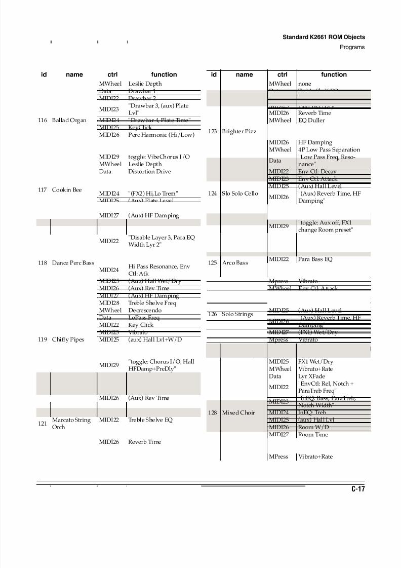
8/21/2019 MR_K2661
http://slidepdf.com/reader/full/mrk2661 409/499
Standard K2661 ROM Objects
Programs
C-17
116 Ballad Organ
MWheel Leslie DepthData Drawbar 1
MIDI22 Drawbar 2MIDI23
"Drawbar 3, (aux) PlateLvl"
MIDI24 "Drawbar 4, Plate Time"MIDI25 KeyClick MIDI26 Perc Harmonic (Hi/Low)MIDI27 "HFDamp, Perc Decay"MIDI28 Cabinet Dist Drive+LopassMIDI29 toggle: VibeChorus I/O
117 Cookin Bee
MWheel Leslie DepthData Distortion DriveMIDI22 Vibrato/ChorusMIDI23 "(FX2) Hi,Lo Gain"MIDI24 "(FX2) Hi,Lo Trem"
MIDI25 (Aux) Plate LevelMIDI26 (Aux) Rev TimeMIDI27 (Aux) HF Damping
118 Dance Perc Bass
MWheel VibratoData Disable Layer 2
MIDI22"Disable Layer 3, Para EQWidth Lyr 2"
MIDI23"Hi Pass Separation, ParaEQ"
MIDI24Hi Pass Resonance, EnvCtl: Atk
MIDI25 (Aux) Hall Wet/DryMIDI26 (Aux) Rev Time
MIDI27 (Aux) HF DampingMIDI28 Treble Shelve Freq
119 Chiffy Pipes
MWheel DecrescendoData LoPass FreqMIDI22 Key Click MIDI23 VibratoMIDI25 (aux) Hall Lvl+W/DMIDI26 Hall TimeMIDI27 Hall Early Ref Lvl
MIDI29"toggle: Chorus I/O, HallHFDamp+PreDly"
120 Pipe Organ 4Data
Subtle Pitch and LP Filtermodulation
MIDI25 (FX1) Rev Time
MIDI26 (Aux) Rev Time
121Marcato StringOrch
MWheel Alt Attack: switchedData Enable Octave LayerMIDI22 Treble Shelve EQMIDI23 Bass Shelve EQMIDI25 Hall Wet/DryMIDI26 Reverb Time
id name ctrl function
122 Adagio Strings
MWheel noneData Treble Shelf EQ
MIDI22 Bass Shelf EQMIDI25 Hall Wet/DryMIDI26 Reverb Time
123 Brighter Pizz
MWheel EQ DullerData ShaperMIDI25 "Hall Wet/Dry, Rev Time"MIDI26 HF Damping
124 Slo Solo Cello
MWheel 4P Low Pass Separation
Data"Low Pass Freq, Reso-nance"
MIDI22 Env Ctl: DecayMIDI23 Env Ctl: Attack MIDI25 (Aux) Hall Level
MIDI26
"(Aux) Reverb Time, HF
Damping"MIDI27 (FX1) Wet/DryMIDI28 (FX1) HF Damping
MIDI29"toggle: Aux off, FX1change Room preset"
Mpress Increase Vibrato Depth
125 Arco Bass
MWheel VibratoData Env Ctl: Attack MIDI22 Para Bass EQMIDI25 (Aux) Hall LevelMIDI26 (FX1) Wet/DryMpress Vibrato
126 Solo Strings
MWheel Env Ctl: Attack
Data Low Pass FreqMIDI22 ShaperMIDI25 (Aux) Hall Level
MIDI26"(Aux) Reverb Time, HFDamping"
MIDI27 (FX1) Wet/DryMpress Vibrato
127 Touch StringsMWheel VibratoData Env Ctl: Atk & ReleaseMIDI25 FX1 Wet/Dry
128 Mixed Choir
MWheel Vibrato+RateData Lyr XFade
MIDI22"EnvCtl: Rel, Notch +ParaTreb Freq"
MIDI23 "InEQ: Bass, ParaTreb,Notch Width"
MIDI24 InEQ: TrebMIDI25 (aux) Hall LvlMIDI26 Room W/DMIDI27 Room TimeMIDI28 Infinite Decay on KeydownMIDI29 Infinite DecayMPress Vibrato+Rate
id name ctrl function
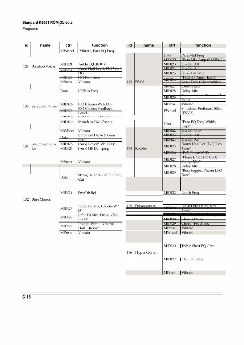
8/21/2019 MR_K2661
http://slidepdf.com/reader/full/mrk2661 410/499
C-18
Standard K2661 ROM Objects
Programs
129 Bamboo Voices
MWheel "Vibrato, Para EQ Freq"Data Boost Vox Layer
MIDI23 Bass EQ (KDFX)MIDI24 Treble EQ (KDFX)
MIDI25(Aux) Hall Level, FX1 Wet/Dry
MIDI26 FX1 Rev TimeMPress Vibrato
130 Syn Orch Power
MWheel Vibrato+RateData LP2Res FreqMIDI22 Env Ctl: Release (faster)MIDI25 (Aux) Reverb TimeMIDI26 FX2 Chorus Wet/Dry
MIDI27FX2 Chorus FeedbackLevel
MIDI28 FX2 Chorus LFO Rate
MIDI29 Switch to FX2 ChorusMPress Vibrato+Rate
131Strummer Gui-tar
MWheel Vibrato
DataEnhancer Drive & Gain(less)
MIDI25 (Aux) Reverb Wet/DryMIDI26 (Aux) HF DampingMIDI27 (Aux) Compression RatioMIDI29 Switch to FX2 PitcherMPress Vibrato
132 Blue Moods
MWheelSlight Vibrato, String Bal-ance
DataString Balance, Gtr Hi Freq
CutMIDI22 EnvCtl: Imp+AttMIDI23 EnvCtl: DecMIDI24 EnvCtl: RelMIDI25 (aux) Hall LvlMIDI26 Hall Time+HFDamp
MIDI27"Enhc Lo Mix, Chorus W/D"
MIDI28Enhc Hi Mix+Drive, Cho-rus FB
MIDI29"toggle: Enhc + Chorus,Hall + Room"
MPress Vibrato
id name ctrl function
133 ES335
MWheel Notch Filt TremoloData Para Mid Freq
MIDI22 "Para Mid Amp (ES335), "MIDI23 EnvCtl: AttMIDI24 EnvCtl: RelMIDI25 (aux) Hall Mix
MIDI26"Hall HFDamp, InEQ:Bass+Treb (Abercrmbie)"
MIDI27 Chorus MixMIDI28 Delay Mix
MIDI29Turns off Semi-Tone PitchBend
MPress Vibrato
PWheelSimulates Fretboard Slide(ES335)
134 Kotolin
MWheel Para EQ AMP
Data "Para EQ Freq, Width,Depth"
MIDI22 EnvCtl: ImpMIDI23 EnvCtl: AttMIDI24 EnvCtl: Rel
MIDI25"(aux) Hall Lvl, (Fx3) RvbTime"
MIDI26 (Fx2) Phase W/D
MIDI27"Phase L/R LFO, (Fx3)Flange Mix"
MIDI28 Delay Mix
MIDI29"Buss toggle:, Phaser LFORate"
MPress Vibrato
135 Dreamguitar
MWheel VibratoData Octave Pitch shift Pad layerMIDI22 Notch Freq
MIDI25"FX1 Rev Mix, (Aux) HallLevel"
MIDI26"(Aux) Pre-Delay, RevTime"
MIDI27 "FX1 Rev W/D, Delay Mix"MIDI28 Chorus DelayMIDI29 Chorus Feedback MPress Vibrato
136 Hyper Guitar
MWheel VibratoData Enhancer Amplitude
MIDI22 Env Ctl: DecayMIDI23 Treble Shelf EQ GainMIDI25 (Aux) Hall LevelMIDI26 FX2 Wet/DryMIDI27 FX2 LFO Rate
MIDI29Toggle: effect to StereoImage
MPress Vibrato
id name ctrl function
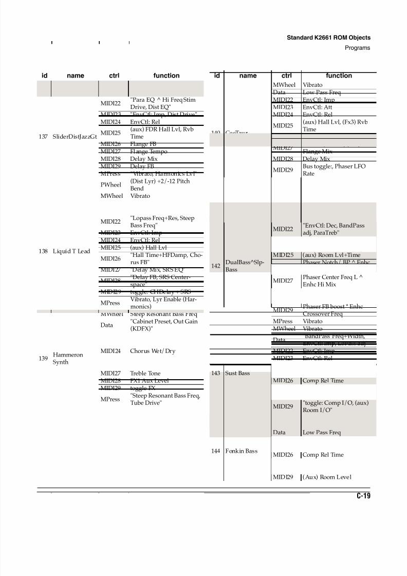
8/21/2019 MR_K2661
http://slidepdf.com/reader/full/mrk2661 411/499
Standard K2661 ROM Objects
Programs
C-19
137 SliderDistJazzGt
MWheel Vibrato/TremoloData Enables Dist Gtr Lyrs
MIDI22 "Para EQ ^ Hi Freq StimDrive, Dist EQ"
MIDI23 "EnvCtl: Imp, Dist Drive"MIDI24 EnvCtl: Rel
MIDI25(aux) FDR Hall Lvl, RvbTime
MIDI26 Flange FBMIDI27 Flange TempoMIDI28 Delay MixMIDI29 Delay FBMPress "Vibrato, Harmonics Lvl"
PWheel(Dist Lyr) +2/-12 PitchBend
138 Liquid T Lead
MWheel Vibrato
Data EnvCtl: Att, LoPassFreq+Res
MIDI22"Lopass Freq+Res, SteepBass Freq"
MIDI23 EnvCtl: ImpMIDI24 EnvCtl: RelMIDI25 (aux) Hall Lvl
MIDI26"Hall Time+HFDamp, Cho-rus FB"
MIDI27 "Delay Mix, SRS EQ"
MIDI28"Delay FB, SRS Center-space"
MIDI29 toggle: CHDelay + SRS
MPress Vibrato, Lyr Enable (Har-monics)
139HammeronSynth
MWheel Steep Resonant Bass Freq
Data"Cabinet Preset, Out Gain(KDFX)"
MIDI22 (Aux) Hall LevelMIDI23 MD Wet/DryMIDI24 Chorus Wet/DryMIDI25 Bass ToneMIDI26 Mid ToneMIDI27 Treble ToneMIDI28 FX1 Aux LevelMIDI29 toggle FX
MPress"Steep Resonant Bass Freq,
Tube Drive"
id name ctrl function
140 CeeTaur
MWheel VibratoData Low Pass Freq
MIDI22 EnvCtl: ImpMIDI23 EnvCtl: AttMIDI24 EnvCtl: Rel
MIDI25(aux) Hall Lvl, (Fx3) RvbTime
MIDI26 (Fx2) Phase W/D
MIDI27Phase L/R LFO, (Fx3)Flange Mix
MIDI28 Delay Mix
MIDI29Bus toggle:, Phaser LFORate
MPress Vibrato
141 Brite Stand-upMWheel Vibrato
Data
"Octave Pitch Shift Layer 2,
(Aux) Ambience Level"
142DualBass^Slp-Bass
MWheel VibratoData toggle: DualBass + SlpBass
MIDI22"EnvCtl: Dec, BandPassadj, ParaTreb"
MIDI23 EnvCtl : Att+ImpMIDI24 EnvCtl: RelMIDI25 (aux) Room Lvl+Time
MIDI26Phaser Notch/ BP ^ EnhcLoDrive+Delay
MIDI27Phaser Center Freq L ^Enhc Hi Mix
MIDI28Phaser Center Freq R Enhc Mid Mix
MIDI29Phaser FB boost * EnhcCrossover Freq
MPress Vibrato
143 Sust Bass
MWheel Vibrato
Data"BandPass Freq+Width,EnvCtl: Imp, LoPass adj"
MIDI22 EnvCtl: ImpMIDI23 EnvCtl: RelMIDI24 In EQ: BassMIDI25 Comp Att TimeMIDI26 Comp Rel TimeMIDI27 Comp RatioMIDI28 Comp ThReshhold
MIDI29 "toggle: Comp I/O, (aux)Room I/O"
MPress Vibrato
144 Fonkin Bass
MWheel VibratoData Low Pass FreqMIDI24 Bass EQ Gain (KDFX)MIDI25 Comp Att TimeMIDI26 Comp Rel TimeMIDI27 Comp RatioMIDI28 Comp ThReshholdMIDI29 (Aux) Room Level
id name ctrl function
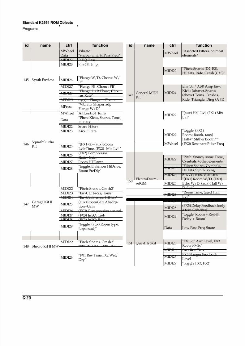
8/21/2019 MR_K2661
http://slidepdf.com/reader/full/mrk2661 412/499
C-20
Standard K2661 ROM Objects
Programs
145 Synth Fretless
MWheel VibratoData "Shaper amt, HiPass Freq"
MIDI22 InEQ: BassMIDI23 EnvCtl: ImpMIDI24 EnvCtl: RelMIDI25 (aux) Hall Lvl
MIDI26"Flange W/D, Chorus W/D"
MIDI27 "Flange FB, Chorus FB"
MIDI28"Flange L/R Phase, Cho-rus Rate"
MIDI29 toggle: Flange + Chorus
MPress"Vibrato, Shaper adj,Flange W/D"
146SquashStudioKit
MWheel AltControl: Toms
Data
"Pitch: Kicks, Snares, Toms,
HiHats"MIDI22 Snare FiltersMIDI23 Kick Filters
MIDI24"EnvCtl: Kicks, Snares,Toms"
MIDI25"(FX1+2)- (aux) RoomLvl+Time, (FX2)- Mix Lvl "
MIDI26(FX2) CompressorRatio+Gain
MIDI27 Room HFDamp
MIDI28"toggle: Enhancer HiDrive,Room PreDly"
MIDI29 Enhancer Hi Delay Time
147Garage Kit IIMW
MWheel Multiple Layer toggleData "Pitch: Kicks, Toms"MIDI22 "Pitch: Snares, Crash2"MIDI23 "EnvCtl: Kicks, Toms"MIDI24 "EnvCtl: Snares, HiHats"
MIDI25(aux) RoomGate Absorp-tion+Gain
MIDI26 (FX3) Compression controlMIDI27 (FX3) InEQ: TrebMIDI28 (FX3) InEQ: Bass
MIDI29"toggle: (aux) Room type,Lopass adj"
148 Studio Kit II MW
MWheel Multiple Layer toggleData "Pitch: Kicks, Toms"
MIDI22 "Pitch: Snares, Crash2"MIDI25
"FX1 Wet/Dry, FX1+2 AuxLevels, Aux Rev Time"
MIDI26"FX1 Rev Time,FX2 Wet/Dry"
id name ctrl function
149General MIDIKit
MWheel"Assorted Filters, on mostelements"
Data "PItch: Kicks (B1, C2), andToms"
MIDI22"Pitch: Snares (D2, E2),HiHats, Ride, Crash (C#3)"
MIDI23"Pitch: Congas, Timbales,many other elements"
MIDI24
EnvCtl / ASR Amp Env:Kicks (above), Snares(above) Toms, Crashes,Ride, Triangle, Ding (A#1)
MIDI25 (FX1) Room W/DMIDI26 Room Rvrb Time
MIDI27"(aux) Hall Lvl, (FX1) MixLvl"
MIDI28 (FX1) CompressorRatio+Threshold+Rel Time
MIDI29"toggle: (FX1)Room+Booth, (aux)Hall+""Slither Booth"""
150ElectroDrum-setGM
MWheel (FX2) Resonant Filter Freq
Data"Filter: Kicks, Toms,assorted other elements"
MIDI22"Pitch: Snares, some Toms,Cymbals,+other elements"
MIDI23"Filter: Snares, Cymbals,HiHats, Synth Boing"
MIDI24 EnvCtl: most elements
MIDI25"(FX1) Room W/D, (FX3)Echo W/D, (aux) Hall W/D+Lvl"
MIDI26"Room Time, (aux) HallLvl"
MIDI27 Hall Late Rvrb Time
MIDI28(FX3) Delay Feedback (onlya few elements)
MIDI29"toggle: Room + ResFilt,Delay + Room"
151 QuestHipKit
MWheel EP Chord TremoloData Low Pass Freq SnareMIDI22 EP Chord Low Pass FreqMIDI23 EP Chord Resonance
MIDI25 "FX1,2,3 Aux Level, FX3Reverb Mix"MIDI26 Aux Rev Time
MIDI27FX3 Flanger FeedbackLevel
MIDI29 "Toggle FX3, FX2"
id name ctrl function
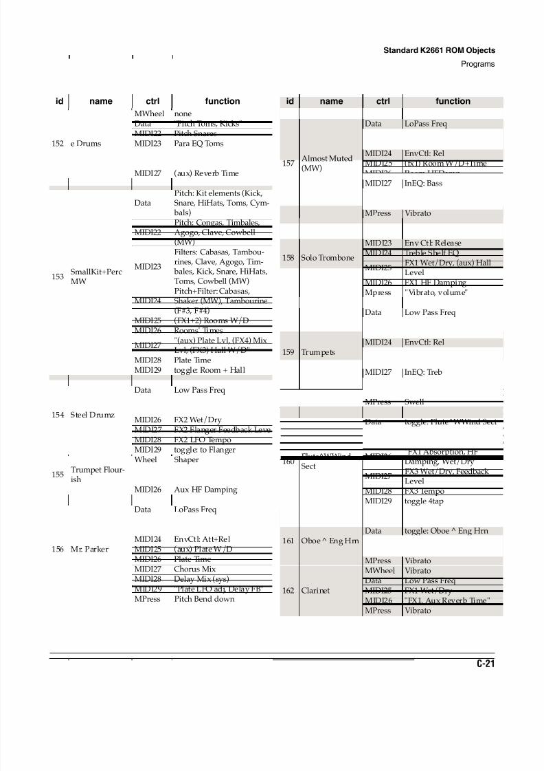
8/21/2019 MR_K2661
http://slidepdf.com/reader/full/mrk2661 413/499
Standard K2661 ROM Objects
Programs
C-21
152 e Drums
MWheel noneData "Pitch Toms, Kicks"
MIDI22 Pitch SnaresMIDI23 Para EQ TomsMIDI25 (aux) Hall LevelMIDI26 "FX1 Wet/Dry, Rev Time"MIDI27 (aux) Reverb Time
153 SmallKit+PercMW
MWheel Cowbell + Shaker Enable
DataPitch: Kit elements (Kick,Snare, HiHats, Toms, Cym-
bals)
MIDI22Pitch: Congas, Timbales,Agogo, Clave, Cowbell(MW)
MIDI23
Filters: Cabasas, Tambou-rines, Clave, Agogo, Tim-
bales, Kick, Snare, HiHats,Toms, Cowbell (MW)
MIDI24Pitch+Filter: Cabasas,Shaker (MW), Tambourine(F#3, F#4)
MIDI25 (FX1+2) Rooms W/DMIDI26 Rooms' Times
MIDI27"(aux) Plate Lvl, (FX4) MixLvl, (FX3) Hall W/D"
MIDI28 Plate TimeMIDI29 toggle: Room + Hall
154 Steel Drumz
MWheel VibratoData Low Pass FreqMIDI 22 ResonanceMIDI25 FX1 Wet/DryMIDI26 FX2 Wet/DryMIDI27 FX2 Flanger Feedback LeveMIDI28 FX2 LFO TempoMIDI29 toggle: to Flanger
155Trumpet Flour-ish
Wheel ShaperData Low Pass FreqMIDI25 "FX1, Aux Reverb Time"MIDI26 Aux HF Damping
156 Mr. Parker
MWheel VibratoData LoPass FreqMIDI22 LoPass ResMIDI23 LoPass Freq
MIDI24 EnvCtl: Att+RelMIDI25 (aux) Plate W/DMIDI26 Plate TimeMIDI27 Chorus MixMIDI28 Delay Mix (sys)MIDI29 "Plate LFO adj, Delay FB"MPress Pitch Bend down
id name ctrl function
157Almost Muted(MW)
MWheel "Vibrato, mute adj"Data LoPass Freq
MIDI22 HiPass FreqMIDI23 EnvCtl: ImpMIDI24 EnvCtl: RelMIDI25 (fx1) Room W/D+TimeMIDI26 Room HFDampMIDI27 InEQ: BassMIDI28 InEQ: TrebMIDI29 EQMorph I/OMPress Vibrato
158 Solo Trombone
MWheel "Vibrato, Low Pass Freq"Data Low Pass FreqMIDI23 Env Ctl: ReleaseMIDI24 Treble Shelf EQ
MIDI25
FX1 Wet/Dry, (aux) Hall
LevelMIDI26 FX1 HF DampingMpress "Vibrato, volume"
159 Trumpets
MWheel VibratoData Low Pass FreqMIDI22 InEQ:BassMIDI23 EnvCtl: ImpMIDI24 EnvCtl: RelMIDI25 (aux) Chamber LvlMIDI26 Chamber Time+HFDampMIDI27 InEQ: TrebMIDI28 Chorus FBMIDI29 Chorus I/O
MPress Swell
160Flute^WWindSect
MWheel Low Pass Freq - FluteData toggle: Flute^WWind SectMIDI22 Fade in Chiff Layer - FluteMIDI25 (Aux) Hall Level (less)
MIDI26"FX1 Absorption, HFDamping, Wet/Dry"
MIDI27FX3 Wet/Dry, FeedbackLevel
MIDI28 FX3 TempoMIDI29 toggle 4tapMPress "Vibrato, WWind Sect"
161 Oboe Eng Hrn
MWheel Low Pass FreqData toggle: Oboe Eng Hrn
MIDI25 "FX1, (aux) Reverb Time"MIDI26 (aux) HF DampingMPress Vibrato
162 Clarinet
MWheel VibratoData Low Pass FreqMIDI25 FX1 Wet/DryMIDI26 "FX1, Aux Reverb Time"MPress Vibrato
id name ctrl function
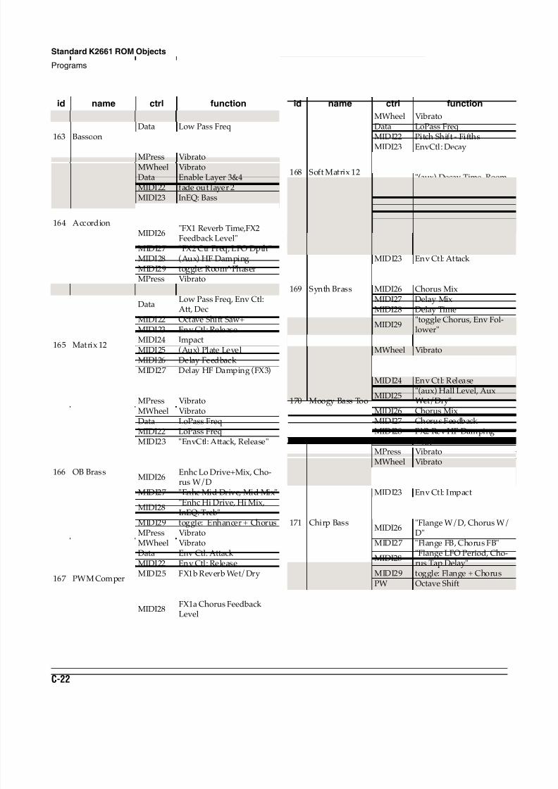
8/21/2019 MR_K2661
http://slidepdf.com/reader/full/mrk2661 414/499
C-22
Standard K2661 ROM Objects
Programs
163 Bassoon
MWheel VibratoData Low Pass Freq
MIDI25 FX1 Wet/DryMIDI26 "FX1, Aux Reverb Time"MPress Vibrato
164 Accordion
MWheel VibratoData Enable Layer 3&4MIDI22 fade out layer 2MIDI23 InEQ: BassMIDI24 InEQ: TrebleMIDI25 FX1 Wet/Dry
MIDI26"FX1 Reverb Time,FX2Feedback Level"
MIDI27 "FX2 Ctr Freq, LFO Dpth"MIDI28 (Aux) HF DampingMIDI29 toggle: Room^Phaser
MPress Vibrato
165 Matrix 12
MWheel Vibrato
DataLow Pass Freq, Env Ctl:Att, Dec
MIDI22 Octave Shift Saw+MIDI23 Env Ctl: ReleaseMIDI24 ImpactMIDI25 (Aux) Plate LevelMIDI26 Delay Feedback MIDI27 Delay HF Damping (FX3)MIDI28 (aux) HF DampingMIDI29 Switch in DelayMPress Vibrato
166 OB Brass
MWheel VibratoData LoPass FreqMIDI22 LoPass FreqMIDI23 "EnvCtl: Attack, Release"MIDI24 EnvCtl: ImpactMIDI25 (aux) Plate Lvl+Time
MIDI26Enhc Lo Drive+Mix, Cho-rus W/D
MIDI27 "Enhc Mid Drive, Mid Mix"
MIDI28"Enhc Hi Drive, Hi Mix,InEQ: Treb"
MIDI29 toggle: Enhancer + ChorusMPress Vibrato
167 PWM Comper
MWheel Vibrato
Data Env Ctl: Attack MIDI22 Env Ctl: ReleaseMIDI25 FX1b Reverb Wet/DryMIDI26 (Aux) Hall LevelMIDI27 FX1a Chorus Wet/Dry
MIDI28FX1a Chorus FeedbackLevel
id name ctrl function
168 Soft Matrix 12
MWheel VibratoData LoPass Freq
MIDI22 Pitch Shift - FifthsMIDI23 EnvCtl: DecayMIDI24 EnvCtl: ReleaseMIDI25 (aux) Hall Level
MIDI26"(aux) Decay Time, RoomSize, HF Damp"
MIDI27 FX3 Delay Wet/DryMIDI28 FX3 Delay Feedback MIDI29 Switch in DelayMPress Vibrato
169 Synth Brass
MWheel VibratoData Low Pass FreqMIDI23 Env Ctl: Attack MIDI24 Env Ctl: Release
MIDI25 (Aux) Hall LevelMIDI26 Chorus MixMIDI27 Delay MixMIDI28 Delay Time
MIDI29"toggle Chorus, Env Fol-lower"
MPress Low Pass Freq Lyr 1
170 Moogy Bass Too
MWheel VibratoData "Low Pass Freq, Impact"MIDI22 ResonanceMIDI24 Env Ctl: Release
MIDI25"(aux) Hall Level, AuxWet/Dry"
MIDI26 Chorus MixMIDI27 Chorus Feedback MIDI28 FX2 Rev HF DampingMIDI29 toggle: Chorus^ EnhancerMPress Vibrato
171 Chirp Bass
MWheel VibratoData HiPass FreqMIDI22 LoPass ResMIDI23 Env Ctl: ImpactMIDI24 EnvCtl: Att+RelMIDI25 (aux) Room Lvl
MIDI26"Flange W/D, Chorus W/D"
MIDI27 "Flange FB, Chorus FB"
MIDI28 "Flange LFO Period, Cho-rus Tap Delay"
MIDI29 toggle: Flange + ChorusPW Octave Shift
id name ctrl function
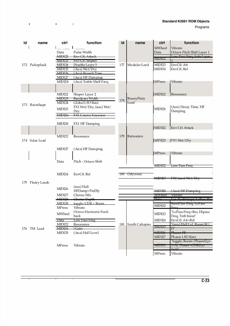
8/21/2019 MR_K2661
http://slidepdf.com/reader/full/mrk2661 415/499
Standard K2661 ROM Objects
Programs
C-23
172 Pulsepluck
MWheel VibratoData Pulse Width
MIDI22 Env Ctl: Attack MIDI23 Env Ctl: ImpactMIDI24 Disable Layer 3MIDI25 (Aux) Wet/DryMIDI26 (Aux) Reverb TimeMIDI27 (Aux) HF DampingMIDI28 (Aux) Treble Shelf Freq
173 Resoshape
MWheel Pitch ModulationData Shaper Layer 1MIDI22 Shaper Layer 2MIDI23 Bandpass WidthMIDI24 Global LFO Rate
MIDI25FX1 Wet/Dry, (aux) Wet/Dry
MIDI26 FX1 Course XcursionMIDI27 FX1 Flange Feedback LevelMIDI28 FX1 HF Damping
174 Solar Lead
MWheel VibratoData Low Pass FreqMIDI22 ResonanceMIDI25 (Aux) Wet/DryMIDI26 (Aux) Reverb TimeMIDI27 (Aux) HF DampingMPress Vibrato
175 Flutey Leads
MWheel VibratoData Pitch - Octave ShiftMIDI22 InEQ: Bass
MIDI23 InEQ: TrebMIDI24 EnvCtl: Rel
MIDI25(aux) Hall Lvl, (FX3) HallMix
MIDI26(aux) HallHFDamp+PreDly
MIDI27 Chorus MixMIDI28 Chorus DepthMIDI29 toggle: CDR + RoomMPress Vibrato
176 TM Lead
MWheelOctave Harmonic Feed-
back Data Low Pass FreqMIDI22 Resonance
MIDI24 ! GainMIDI25 (Aux) Hall LevelMIDI26 (Aux) Wet/DryMIDI27 FX3 Delay TimeMPress Vibrato
id name ctrl function
177 Modular Lead
MWheel VibratoData Octave Pitch Shift Layer 1
MIDI22 Low Pass Freq, fade Layer1
MIDI23 EnvCtl: AttMIDI24 EnvCtl: RelMIDI25 (aux) LevelMIDI27 Chorus Feedback MPress Vibrato
178BrassyFlutyLead
MWheel VibratoData Low Pass FreqMIDI22 ResonanceMIDI24 Env Ctl: ReleaseMIDI25 (Aux) Hall Level
MIDI26(Aux) Decay Time, HFDamping
MPress Swell
179 Retrosiren
MWheel VibratoData Low Pass FreqMIDI22 Env Ctl: Attack MIDI23 Env Ctl: ImpactMIDI24 Env Ctl: ReleaseMIDI25 FX1 Wet/DryMIDI26 (Aux) Hall LevelMIDI27 (Aux) Reverb TimeMPress Vibrato
180 Odysseus
MWheel VibratoData Bandpass FreqMIDI22 Low Pass Freq
MIDI23 Sine + FreqMIDI24 Low Pass FreqMIDI25 FX1 (aux) Wet/DryMIDI26 FX1 Loop LevelMIDI27 (Aux) SpacingMIDI28 (Aux) HF Damping
181 Synth Caliopies
MWheel VibratoData Lyr disable(up); LoPass Res
MIDI22BandPass Freq; LoPassFreq
MIDI23"LoPass Freq+Res, HipassFreq, Treb boost"
MIDI24 EnvCtl: Att+Rel
MIDI25"(aux) Hall Lvl, Room W/
D"MIDI26 Phaser FBMIDI27 Phaser LFO Rate
MIDI29"toggle: Room+Phaser(Lyr1+3), Phaser+CDR(Lyr2+4)"
MPress Vibrato
id name ctrl function
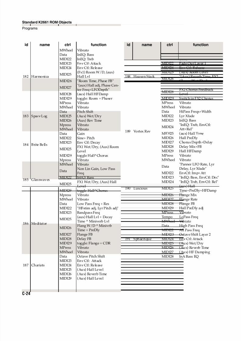
8/21/2019 MR_K2661
http://slidepdf.com/reader/full/mrk2661 416/499
C-24
Standard K2661 ROM Objects
Programs
182 Harmonica
MWheel VibratoData InEQ: Bass
MIDI22 InEQ: TrebMIDI23 Env Ctl: Attack MIDI24 Env Ctl: Release
MIDI25(Fx1) Room W/D, (aux)Hall Lvl
MIDI26 "Room Time, Phase FB"
MIDI27"(aux) Hall adj, Phase Cen-ter Freq+LFODepth"
MIDI28 (aux) Hall HFDampMIDI29 toggle: Room + PhaserMPress Vibrato
183 Space Log
MWheel VibratoData Pitch ShiftMIDI25 (Aux) Wet/Dry
MIDI26 (Aux) Rev TimeMpress Vibrato
184 Brite Bells
MWheel VibratoData GainMIDI22 Sine+ PitchMIDI23 Env Ctl: Decay
MIDI25FX1 Wet/Dry, (Aux) RoomLevel
MIDI29 toggle Hall ChorusMpress Vibrato
185 Glasswaves
MWheel Vibrato
DataNon Lin Gain, Low PassFreq
MIDI22 InEQ: BassMIDI25
FX1 Wet/Dry, (Aux) HallLevel
MIDI29 toggle Hall^ChorusMpress Vibrato
186 Meditator
MWheel VibratoData Low Pass Freq + ResMIDI22 "HFstim adj, Lyr Pitch adj"MIDI23 Bandpass Freq
MIDI25(aux) Hall Lvl + DecayTime ^ Miniverb Lvl
MIDI26Flang W/D MinivrbTime + PreDly
MIDI27 Flange FB
MIDI28 Delay FBMIDI29 toggle: Flange + CDRMPress Vibrato
187 Chariots
MWheel VibratoData Octave Pitch ShiftMIDI23 Env Ctl: AttackMIDI24 Env Ctl: ReleaseMIDI25 (Aux) Hall LevelMIDI26 (Aux) Reverb TimeMIDI29 (Aux) Hall Level
id name ctrl function
188 Heaven Stack
MWheel Vibrato
DataHi Freq Stimulator Drive
(less)MIDI22 Fade Out Layer 1MIDI24 Env Ctl: ReleaseMIDI25 (Aux) Room Level
MIDI26"(Aux) Reverb Time, FX2Chorus Wet/Dry"
MIDI27 FX2 Chorus LFO Rate
MIDI28FX2 Chorus FeedbackLevel
MIDI29 Switch in FX2 ChorusMPress Vibrato
189 Vortex Rev
MWheel VibratoData HiPass Freqs+WidthMIDI22 Lyr Xfade
MIDI23 InEQ: Bass
MIDI24"InEQ: Treb, EnvCtl:Att+Rel"
MIDI25 (aux) Hall TimeMIDI26 Hall PreDlyMIDI27 Chorus Depth+DelayMIDI28 Delay Mix+FBMIDI29 Hall HFDampMPress Vibrato
190 Luscious
MWheel Vibrato
Data"Panner LFO Rate, LyrDelay, Lyr Xfade"
MIDI22 EnvCtl: Imp+Att
MIDI23 "InEQ: Bass, EnvCtl: Dec"MIDI24 "InEQ: Treb, EnvCtl: Rel"
MIDI25(aux) HallTime+PreDly+HFDamp
MIDI26 Flange MixMIDI27 Flange RateMIDI28 Flange FBMIDI29 Hall PreDly adjMPress VibratoTempo LoPass Freq
191 Sphaerique
MWheel VibratoData High Pass FreqMIDI22 All Pass FreqMIDI23 Octave Shift Layer 2
MIDI24 Env Ctl: Attack MIDI25 (Aux) Wet/DryMIDI26 (Aux) Reverb TimeMIDI27 (Aux) HF DampingMIDI28 InA Bass EQ
id name ctrl function
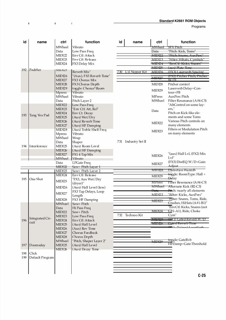
8/21/2019 MR_K2661
http://slidepdf.com/reader/full/mrk2661 417/499
Standard K2661 ROM Objects
Programs
C-25
192 Padifier
MWheel VibratoData Low Pass Freq
MIDI22 Env Ctl: Attack MIDI23 Env Ctl: ReleaseMIDI24 FX3 Delay Mix
MIDI25"(Aux) Hall Level, FX3Reverb Mix"
MIDI26 "(Aux), FX3 Reverb Time"MIDI27 FX3 Chorus MixMIDI28 FX3 Chorus DepthMIDI29 toggle: Chorus RoomMpress Vibrato
193 Tang Vox Pad
MWheel VibratoData Pitch Layer 2MIDI22 Low Pass FreqMIDI23 "Env Ctl: Att, Rel"
MIDI24 Env Ct: DecayMIDI25 (Aux) Wet/DryMIDI26 (Aux) Reverb TimeMIDI27 (Aux) HF DampingMIDI28 (Aux) Treble Shelf FreqMpress Vibrato
194 Interference
MWheel WrapData ShaperMIDI25 (Aux) Room LevelMIDI26 (Aux) HF DampingMIDI27 FX1 4 Tap Mix
195 One Shot
MWheel VibratoData LPGate Freq
MIDI22 Saw+ Pitch Layer 1MIDI23 Saw+ Pitch Layer 2MIDI24 Env Ctl: Release
MIDI25"FX3, Aux Wet/Dry(dryer)"
MIDI26 (Aux) Hall Level (less)
MIDI27FX3 Tap Delays, LoopLength
MIDI28 FX3 HF Damping
196Integrated Cir-
cuit
MWheel Saw+ PitchData Hi Pass FreqMIDI22 Saw+ PitchMIDI23 Low Pass FreqMIDI24 Env Ctl: Attack
MIDI25 (Aux) Hall LevelMIDI26 (Aux) Rev TimeMIDI27 Chorus Feedback MIDI28 Chorus Depth
197 DoomsdayMWheel "Pitch, Shaper Layer 2"MIDI25 (Aux) Hall LevelMIDI26 (Aux) Decay Time
198 Click 199 Default Program
id name ctrl function
730 L'il Nipper Kit
MWheel SFX PitchData "Pitch: Kick, Toms"
MIDI22 "Pitch: Snares, AuxPerc"MIDI23 "Filter: Hihats, Cymbals"MIDI24 "EnvCtl: Kicks, Snares"MIDI25 (aux) Plate TimeMIDI26 (FX3) Laserverb Spacing
MIDI27(FX2) Pitcher Pitch, PitcherW/D
MIDI28 Pitcher control
MIDI29Laserverb Delay+Con-tour+FB
MPress AuxPerc Pitch
731 Industry Set II
MWheel Filter Resonance (A#4-C5)
Data
"AltControl on some lay-ers,"
Pitch on Kick-like ele-ments and some Toms
MIDI22Various Pitch controls onmany elements
MIDI23Filters or Modulation Pitchon many elements
MIDI24EnvCtl: assorted kinds ofcontrol on many elements
MIDI25(FX2) Flange W/D, InEQ:Bass
MIDI26"(aux) Hall Lvl, (FX2) MixLvl"
MIDI27(FX3) DistEQ W/D+GainAdjust
MIDI28 Distortion Warmth
MIDI29toggle: RoomType: Hall +Delay
MPress Filter Resonance (A#4-C5)
732 Technoo Kit
MWheel Alternate Kick (B2-C3)Data Pitch: nearly all elementsMIDI22 "Filter: Kicks, AuxPerc"
MIDI23"Filter: Snares, Toms, Ride,Crashes, HiHats (A#1-B1)"
MIDI24"EnvCtl: Kicks, Snares (notG#1-A1), Ride, ChokeCym"
MIDI25 (FX1) Gated Reverb W/D
MIDI26 Gated Reverb TimeMIDI27
(FX1+2) (aux) LaserVerbLvl
MIDI28 (FX4) LaserVerb Lvl
MIDI29toggle: GateRvbHFDamp+Gate Threshold
id name ctrl function
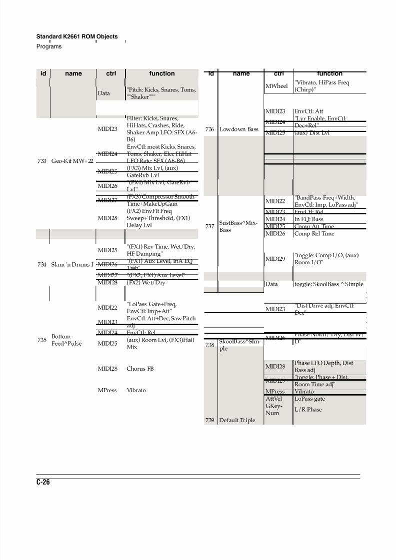
8/21/2019 MR_K2661
http://slidepdf.com/reader/full/mrk2661 418/499
C-26
Standard K2661 ROM Objects
Programs
733 Geo-Kit MW+22
MWheel Multiple Layer toggle
Data"Pitch: Kicks, Snares, Toms,
""Shaker"""MIDI22
Crossfade to tertiary Kicks;Pitch: Elec. Snare only
MIDI23
Filter: Kicks, Snares,HiHats, Crashes, Ride,Shaker Amp LFO: SFX (A6-B6)
MIDI24EnvCtl: most Kicks, Snares,Toms, Shaker, Elec HiHatLFO Rate: SFX (A6-B6)
MIDI25(FX3) Mix Lvl, (aux)GateRvb Lvl
MIDI26"(FX4) Mix Lvl, GateRvbLvl"
MIDI27 (FX3) Compressor Smooth-Time+MakeUpGain
MIDI28(FX2) EnvFlt FreqSweep+Threshold, (FX1)Delay Lvl
MIDI29toggle: Compressor +ChorDelay
734 Slam 'n Drums I
MIDI25"(FX1) Rev Time, Wet/Dry,HF Damping"
MIDI26"(FX1) Aux Level, InA EQTreb"
MIDI27 "(FX2, FX4) Aux Level"MIDI28 (FX2) Wet/Dry
735Bottom-Feed^Pulse
MWheel VibratoData toggle: BottomFeed Pulse
MIDI22"LoPass Gate+Freq,EnvCtl: Imp+Att"
MIDI23EnvCtl: Att+Dec, Saw Pitchadj
MIDI24 EnvCtl: Rel
MIDI25(aux) Room Lvl, (FX3)HallMix
MIDI26 Chorus MixMIDI27 Chorus RateMIDI28 Chorus FB
MIDI29toggle: Chorus(4Tap) +Flange
MPress Vibrato
id name ctrl function
736 Lowdown Bass
MWheel"Vibrato, HiPass Freq(Chirp)"
Data LoPass GateMIDI22 EnvCtl: ImpMIDI23 EnvCtl: Att
MIDI24"Lyr Enable, EnvCtl:Dec+Rel"
MIDI25 (aux) Dist Lvl
MIDI26"Dist Drive, Mid EQ cut,Flange W/D"
MIDI27 "InEQ: Bass, Flange FB"MIDI28 Cab HiPassMIDI29 toggle: EQ + FlangeMPress Vibrato
737SustBass^Mix-Bass
MWheel "Vibrato, LoPass Freq"Data toggle: SustBass + MixBass
MIDI22 "BandPass Freq+Width,EnvCtl: Imp, LoPass adj"
MIDI23 EnvCtl: RelMIDI24 In EQ: BassMIDI25 Comp Att TimeMIDI26 Comp Rel TimeMIDI27 Comp RatioMIDI28 Comp Threshhold
MIDI29"toggle: Comp I/O, (aux)Room I/O"
MPress Vibrato
738SkoolBass^SIm-ple
MWheel VibratoData toggle: SkoolBass SImple
MIDI22 "Pulse Width+Freq, Pitchadj, EnvCtl: Imp+Att"
MIDI23"Dist Drive adj, EnvCtl:Dec"
MIDI24 EnvCtl: RelMIDI25 (aux) Room Lvl
MIDI26Phase Notch/ Dry, Dist W/D"
MIDI27"Phase Center Freq, DistDrive adj
MIDI28Phase LFO Depth, DistBass adj
MIDI29"toggle: Phase + Dist,Room Time adj"
MPress VibratoAttVel LoPass gateGKey-Num
L/R Phase
739 Default Triple
id name ctrl function
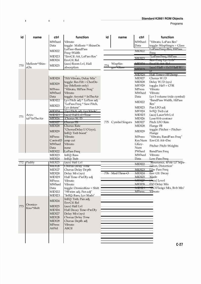
8/21/2019 MR_K2661
http://slidepdf.com/reader/full/mrk2661 419/499
Standard K2661 ROM Objects
Programs
C-27
770Mellostr^Shin-eOn
MWheel VibratoData toggle: Mellostr ShineOn
MIDI22 LoPass+BandPassFreq+Width
MIDI23 "EnvCtl: Att, LoPass Res"MIDI24 EnvCtl: Rel
MIDI25(aux) Room Lvl, Hallabsorption
MIDI26 "Filt Res, Chorus FB"MIDI27 "Filt Freq, Chorus Rate"MIDI28 "Filt Vibrato, Delay Mix"
MIDI29toggle: Res Filt + ChorDe-lay (Mellostr only)
MPress "Vibrato, HiPass Freq"
771Arys-tal^InTheAir
MWheel VibratoData toggle: Arystal InTheAir
MIDI22 Lyr Pitch adj LoPass adj
MIDI23"LoPass Freq Saw Pitch,Lyr detune"
MIDI24 "Lyr Pitch adj, Lyr Xfade"MIDI25 (aux) Hall Lvl+TimeMIDI26 Chorus W/DMIDI27 Chorus FBMIDI28 Chorus Rate
MIDI29"ChorusDelay I/O (sys),InEQ: Treb boost"
MPress VibratoControlD amp cut
772 Padify
MWheel Vibrato
Data noneMIDI22 LoPass FreqMIDI23 InEQ: BassMIDI24 InEQ: TrebMIDI25 (aux) Hall LvlMIDI26 Chorus Delay TimeMIDI27 Chorus Delay DepthMIDI28 Delay Mix (sys)MIDI29 Hall Time+PreDly adjMPress Vibrato
773Oronico-Kno^Shift
MWheel VibratoData toggle: OronicoKno + ShiftMIDI22 "HFstim adj, Pan adj"MIDI23 "InEQ: Bass, Lyr Xfade"
MIDI24 InEQ: Treb, Pan adj,EnvCtl: Rel
MIDI25 (aux) Hall LvlMIDI26 Hall Decay Time+PreDlyMIDI27 Delay Mix (sys)MIDI28 Chorus Delay TimeMIDI29 Chorus Depth adjMPress VibratoAttVel AltCtl
id name ctrl function
774WispSin-grs^Glass
MWheel "Vibrato, LoPass Res"Data toggle: WispSingrs + Glass
MIDI22 LoPass Freq+Res, HiPassFreq
MIDI23"LoPass Freq, HiPassRes+Freq, Lyr Lvls"
MIDI24 EnvCtl: Att+Rel
MIDI25(aux) Hall + (fx1) Hall W/D
MIDI26 Hall Times+HFDampMIDI27 Chorus W/DMIDI28 Delay W/D (sys)MIDI29 toggle: Hall + CDRMPress Vibrato
775 Cymbal Singers
MWheel VibratoData Lyr 3 volume (ride cymbal)
MIDI22 "BandPass Width, HiPassRes"
MIDI23 Pan LFO adjMIDI24 InEQ: Treb cutMIDI25 (aux) LaserVrb LvlMIDI26 LaserVrb contourMIDI27 Pitch LFO RateMIDI28 Flange FB
MIDI29toggle: Pitcher + Pitcher-Flange
MPress "Vibrato, BandPass Freq"KeyNum EnvCtl: Att+DecGKey-
Num
Pitcher Pitch+Weights
PWheel BandPass Freq
776 Mad Three-O
MWheel VibratoData Low Pass Freq
MIDI22"Resonance, 4Pole LP Sepa-ration, Distortion"
MIDI23 Low Pass FreqMIDI24 Env Ctl: DecayMIDI25 XfadeMIDI27 (Aux) LevelMIDI28 FX3 Delay MixMIDI29 "FX3 Flange Mix, Rvb Mix"MPress Vibrato
id name ctrl function
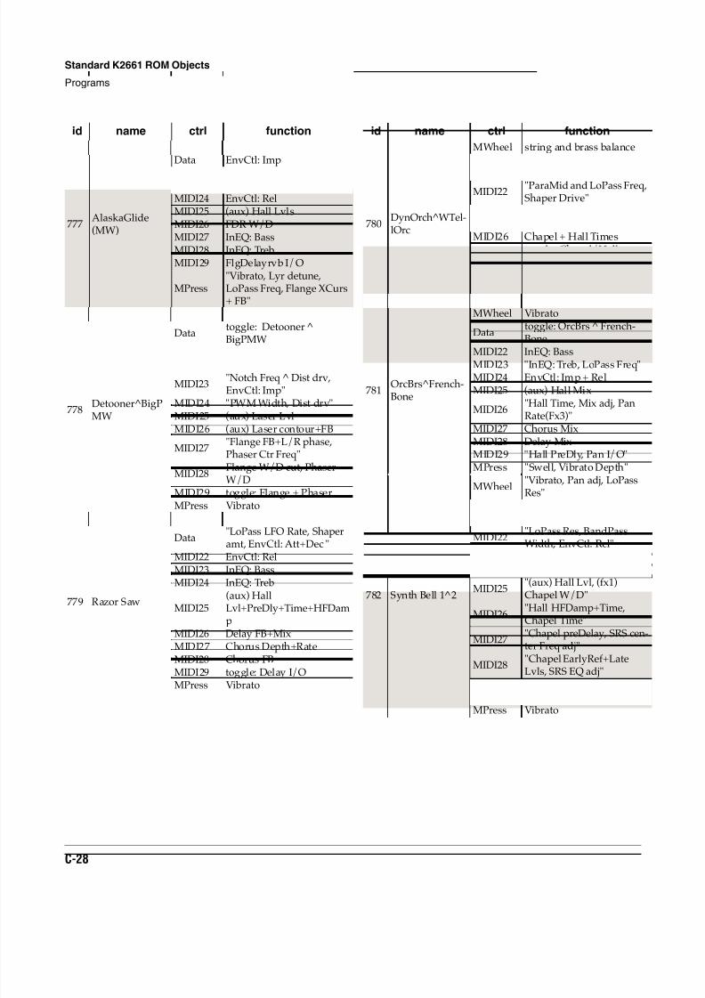
8/21/2019 MR_K2661
http://slidepdf.com/reader/full/mrk2661 420/499
C-28
Standard K2661 ROM Objects
Programs
777AlaskaGlide(MW)
MWheel toggle: Alaska + GlideData EnvCtl: Imp
MIDI22 EnvCtl: AttMIDI23 EnvCtl: DecMIDI24 EnvCtl: RelMIDI25 (aux) Hall LvlsMIDI26 FDR W/DMIDI27 InEQ: BassMIDI28 InEQ: TrebMIDI29 FlgDelayrvb I/O
MPress"Vibrato, Lyr detune,LoPass Freq, Flange XCurs+ FB"
778Detooner^BigPMW
MWheel Vibrato
Datatoggle: Detooner BigPMW
MIDI22 "P5th jump LoPass Freq,EnvCtl: Att+Rel"
MIDI23"Notch Freq ^ Dist drv,EnvCtl: Imp"
MIDI24 "PWM Width, Dist drv"MIDI25 (aux) Laser LvlMIDI26 (aux) Laser contour+FB
MIDI27"Flange FB+L/R phase,Phaser Ctr Freq"
MIDI28Flange W/D cut, PhaserW/D
MIDI29 toggle: Flange + PhaserMPress Vibrato
779 Razor Saw
MWheel VibratoData
"LoPass LFO Rate, Shaperamt, EnvCtl: Att+Dec "
MIDI22 EnvCtl: RelMIDI23 InEQ: BassMIDI24 InEQ: Treb
MIDI25(aux) HallLvl+PreDly+Time+HFDamp
MIDI26 Delay FB+MixMIDI27 Chorus Depth+RateMIDI28 Chorus FBMIDI29 toggle: Delay I/OMPress Vibrato
id name ctrl function
780DynOrch^WTel-lOrc
MWheel string and brass balance
Datatoggle: DynOrch ^ WTel-
lOrchMIDI22
"ParaMid and LoPass Freq,Shaper Drive"
MIDI23 "Shaper amt, LoPass Freq"MIDI25 (aux) Hall Lvl cutMIDI26 Chapel + Hall Times
MIDI29toggle: Chapel/Hall +Hall/Room
MPress"(DynOrch) Volume swell,shaper amt"
SostPd "Lyr enable, Room Time"
781OrcBrs^French-Bone
MWheel Vibrato
Datatoggle: OrcBrs French-Bone
MIDI22 InEQ: BassMIDI23 "InEQ: Treb, LoPass Freq"MIDI24 EnvCtl: Imp + RelMIDI25 (aux) Hall Mix
MIDI26"Hall Time, Mix adj, PanRate(Fx3)"
MIDI27 Chorus MixMIDI28 Delay MixMIDI29 "Hall PreDly, Pan I/O"MPress "Swell, Vibrato Depth"
782 Synth Bell 1^2
MWheel"Vibrato, Pan adj, LoPassRes"
Data"toggle: Synth Bells 1 + 2,AltCtl adj"
MIDI22"LoPass Res, BandPassWidth, EnvCtl: Rel"
MIDI23 Pan adjMIDI24 Pitch LFO adj
MIDI25"(aux) Hall Lvl, (fx1)Chapel W/D"
MIDI26"Hall HFDamp+Time,Chapel Time"
MIDI27"Chapel preDelay, SRS cen-ter Freq adj"
MIDI28"Chapel EarlyRef+LateLvls, SRS EQ adj"
MIDI29 toggle: Chapel + SRS
BKeyNu EnvCtl: Att+Dec+RelMPress Vibrato
id name ctrl function
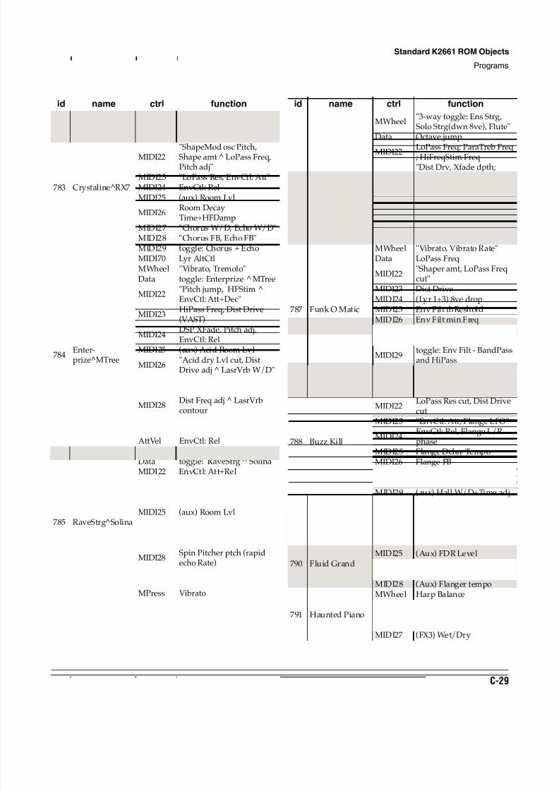
8/21/2019 MR_K2661
http://slidepdf.com/reader/full/mrk2661 421/499
Standard K2661 ROM Objects
Programs
C-29
783 Crystaline^RX7
MWheel"Shaper ctl, Vibrato ^ Panadj"
Data toggle: Crystaline RX7
MIDI22"ShapeMod osc Pitch,Shape amt LoPass Freq,Pitch adj"
MIDI23 "LoPass Res, EnvCtl: Att"MIDI24 EnvCtl: RelMIDI25 (aux) Room Lvl
MIDI26Room DecayTime+HFDamp
MIDI27 "Chorus W/D, Echo W/D"MIDI28 "Chorus FB, Echo FB"MIDI29 toggle: Chorus + EchoMIDI70 Lyr AltCtl
784Enter-prize^MTree
MWheel "Vibrato, Tremolo"
Data toggle: Enterprize MTree
MIDI22"Pitch jump, HFStim ^EnvCtl: Att+Dec"
MIDI23HiPass Freq, Dist Drive(VAST)
MIDI24DSP XFade, Pitch adj,EnvCtl: Rel
MIDI25 (aux) Acid Room Lvl
MIDI26"Acid dry Lvl cut, DistDrive adj ^ LasrVrb W/D"
MIDI27Dist warmth ^ LasrVrbDelay Time
MIDI28Dist Freq adj ^ LasrVrbcontour
MIDI29 Distortion I/OMPress "Vibrato, Tremolo"AttVel EnvCtl: Rel
785 RaveStrg^Solina
MWheel "Vibrato, Lyr detune(Sol)"Data toggle: RaveStrg SolinaMIDI22 EnvCtl: Att+Rel
MIDI23"EnvCtl: Dec ^ Ptch mod,Notch LFO Rate"
MIDI24 "Flange Mix, Spin W/D"MIDI25 (aux) Room Lvl
MIDI26 Spin Pitcher Mix ^MovDelay W/D
MIDI27 Spin Pitcher Weights
MIDI28 Spin Pitcher ptch (rapidecho Rate)
MIDI29"toggle: Spin I/O, RoomHFDamp+Time"
MPress Vibrato
id name ctrl function
786 Mellotron (MW)
MWheel"3-way toggle: Ens Strg,Solo Strg(dwn 8ve), Flute"
Data Octave jumpMIDI22
LoPass Freq; ParaTreb Freq; HiFreqStim Freq
MIDI23"Dist Drv, Xfade dpth;ParaTreb dpth; HFStimDrv"
MIDI25 (aux) Hall LvlMIDI26 Hall TimeMIDI27 Room LvlMIDI28 Room TimeMPress Vibrato
787 Funk O Matic
MWheel "Vibrato, Vibrato Rate"Data LoPass Freq
MIDI22
"Shaper amt, LoPass Freq
cut"MIDI23 Dist DriveMIDI24 (Lyr 1+3) 8ve dropMIDI25 Env Filt thResholdMIDI26 Env Filt min FreqMIDI27 (aux) Sweep Filt W/DMIDI28 (aux) Sweep Filt min Freq
MIDI29toggle: Env Filt - BandPassand HiPass
MPress "Vibrato, Lyr detune"
788 Buzz Kill
MWheel Pitch modulationData LoPass Freq
MIDI22LoPass Res cut, Dist Drive
cutMIDI23 "EnvCtl: Att, Flange LFO"
MIDI24EnvCtl: Rel, Flange L/Rphase
MIDI25 Flange Delay TempoMIDI26 Flange FBMIDI27 (aux) CDR Lvl cutMIDI28 (aux) Delay MixMIDI29 (aux) Hall W/D+Time adjMPress LoPass Freq
789 Grand+Elec 1MWheel Lyr Balance
MIDI25"(aux) Hall Lvl, Room W/D"
790 Fluid Grand
Data Wet/Dry Mix
MIDI25 (Aux) FDR LevelMIDI26 (Aux) Wet/Dry, Delay MixMIDI27 (Aux) Flanger MixMIDI28 (Aux) Flanger tempo
791 Haunted Piano
MWheel Harp Balance
MIDI25(Aux) FLRev Level, RevTime
MIDI26 Flange TempoMIDI27 (FX3) Wet/Dry
id name ctrl function
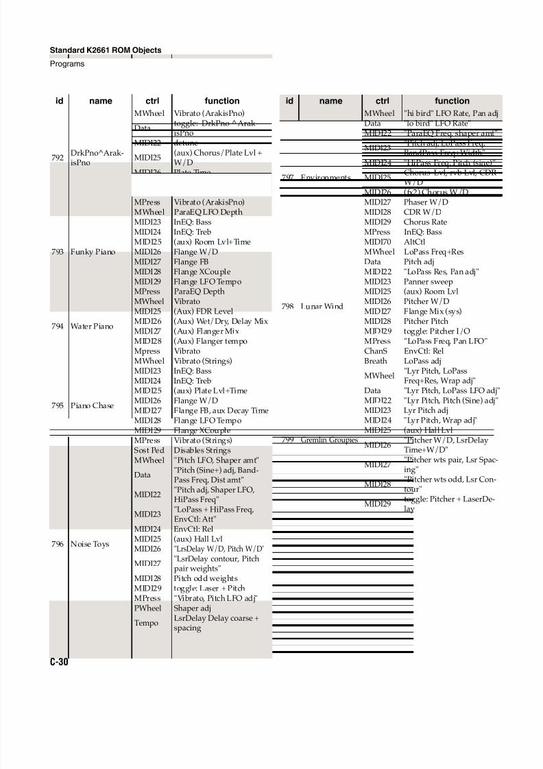
8/21/2019 MR_K2661
http://slidepdf.com/reader/full/mrk2661 422/499
C-30
Standard K2661 ROM Objects
Programs
792DrkPno^Arak-isPno
MWheel Vibrato (ArakisPno)
Datatoggle: DrkPno ^ Arak-
isPnoMIDI22 detune
MIDI25(aux) Chorus/Plate Lvl +W/D
MIDI26 Plate TimeMIDI27 Chorus FBMIDI28 Chorus MixMPress Vibrato (ArakisPno)
793 Funky Piano
MWheel ParaEQ LFO DepthMIDI23 InEQ: BassMIDI24 InEQ: TrebMIDI25 (aux) Room Lvl+TimeMIDI26 Flange W/DMIDI27 Flange FB
MIDI28 Flange XCoupleMIDI29 Flange LFO TempoMPress ParaEQ Depth
794 Water Piano
MWheel VibratoMIDI25 (Aux) FDR LevelMIDI26 (Aux) Wet/Dry, Delay MixMIDI27 (Aux) Flanger MixMIDI28 (Aux) Flanger tempoMpress Vibrato
795 Piano Chase
MWheel Vibrato (Strings)MIDI23 InEQ: BassMIDI24 InEQ: TrebMIDI25 (aux) Plate Lvl+Time
MIDI26 Flange W/DMIDI27 Flange FB, aux Decay TimeMIDI28 Flange LFO TempoMIDI29 Flange XCoupleMPress Vibrato (Strings)Sost Ped Disables Strings
796 Noise Toys
MWheel "Pitch LFO, Shaper amt"
Data"Pitch (Sine+) adj, Band-Pass Freq, Dist amt"
MIDI22"Pitch adj, Shaper LFO,HiPass Freq"
MIDI23"LoPass + HiPass Freq,EnvCtl: Att"
MIDI24 EnvCtl: Rel
MIDI25 (aux) Hall LvlMIDI26 "LrsDelay W/D, Pitch W/D"
MIDI27"LsrDelay contour, Pitchpair weights"
MIDI28 Pitch odd weightsMIDI29 toggle: Laser + PitchMPress "Vibrato, Pitch LFO adj"PWheel Shaper adj
TempoLsrDelay Delay coarse +spacing
id name ctrl function
797 Environments
MWheel "hi bird" LFO Rate, Pan adjData "lo bird" LFO Rate"
MIDI22 "ParaEQ Freq, shaper amt"MIDI23
"Pitch adj, LoPass Freq,BandPass Freq+Width"
MIDI24 "HiPass Freq, Pitch (sine)"
MIDI25Chorus Lvl, rvb Lvl, CDRW/D
MIDI26 (fx2) Chorus W/DMIDI27 Phaser W/DMIDI28 CDR W/DMIDI29 Chorus RateMPress InEQ: BassMIDI70 AltCtl
798 Lunar Wind
MWheel LoPass Freq+ResData Pitch adj
MIDI22 "LoPass Res, Pan adj"MIDI23 Panner sweepMIDI25 (aux) Room LvlMIDI26 Pitcher W/DMIDI27 Flange Mix (sys)MIDI28 Pitcher PitchMIDI29 toggle: Pitcher I/OMPress "LoPass Freq, Pan LFO"ChanS EnvCtl: RelBreath LoPass adj
799 Gremlin Groupies
MWheel"Lyr Pitch, LoPassFreq+Res, Wrap adj"
Data "Lyr Pitch, LoPass LFO adj"
MIDI22 "Lyr Pitch, Pitch (Sine) adj"MIDI23 Lyr Pitch adjMIDI24 "Lyr Pitch, Wrap adj"MIDI25 (aux) Hall Lvl
MIDI26"Pitcher W/D, LsrDelayTime+W/D"
MIDI27"Pitcher wts pair, Lsr Spac-ing"
MIDI28"Pitcher wts odd, Lsr Con-tour"
MIDI29toggle: Pitcher + LaserDe-lay
id name ctrl function

8/21/2019 MR_K2661
http://slidepdf.com/reader/full/mrk2661 423/499
Contemporary ROM Block Objects
D-1
Appendix D
Contemporary ROM Block Objects
This Appendix describes the Contemporary ROM objects provided with your K2661.
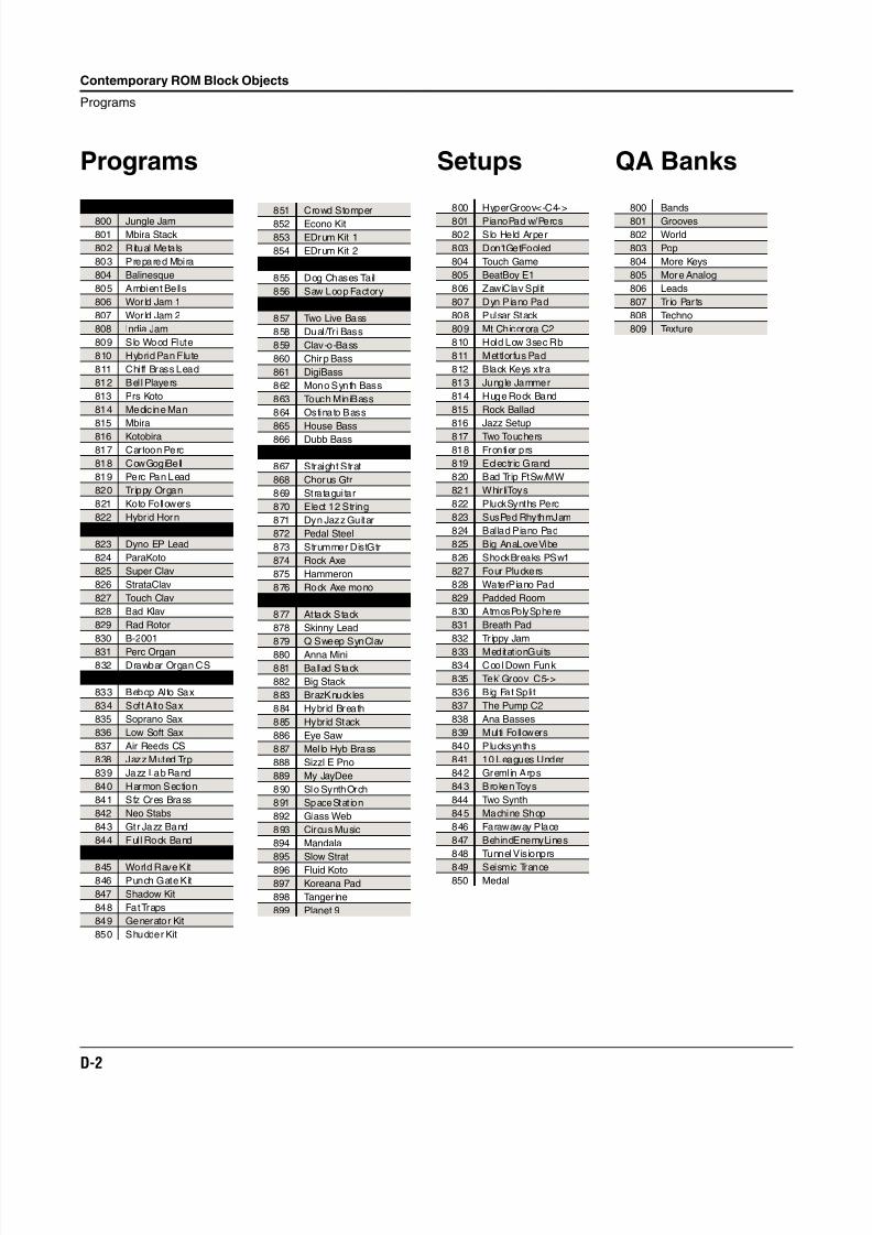
8/21/2019 MR_K2661
http://slidepdf.com/reader/full/mrk2661 424/499
D-2
Contemporary ROM Block Objects
Programs
Programs
Ethnic / World Instruments
800 Jungle Jam
801 Mbira Stack
802 Ritual Metals
803 Prepared Mbira
804 Balinesque
805 Ambient Bells
806 Wor ld Jam 1
807 Wor ld Jam 2
808 India Jam
809 Slo Wood Flute
810 Hybrid Pan Flute
811 Chiff Brass Lead
812 Bel l Players
813 Prs Koto
814 Medicine Man
815 Mbira
816 Kotobira
817 Cartoon Perc
818 CowGogiBell
819 Perc Pan Lead
820 Trippy Organ
821 Koto Followers
822 Hybr id Horn
Keyboards
823 Dyno EP Lead
824 ParaKoto
825 Super Clav
826 StrataClav
827 Touch Clav
828 Bad Klav
829 Rad Rotor
830 B-2001
831 Perc Organ
832 Drawbar Organ CS
Brass and Reeds
833 Bebop Al to Sax
834 Soft Alto Sax
835 Soprano Sax
836 Low Soft Sax
837 Air Reeds CS
838 Jazz Muted Trp
839 Jazz Lab Band
840 Harmon Section
841 Sfz Cres Brass
842 Neo Stabs
843 Gtr Jazz Band
844 Ful l Rock Band
Drum Kits
845 World Rave Kit846 Punch Gate Kit
847 Shadow Kit
848 Fat Traps
849 Generator Kit
850 Shudder Kit
851 Crowd Stomper
852 Econo Kit
853 EDrum Kit 1
854 EDrum Kit 2
Loops
855 Dog Chases Tail
856 Saw Loop Factory
Basses
857 Two Live Bass
858 Dual /Tri Bass
859 Clav-o-Bass
860 Chirp Bass
861 DigiBass
862 Mono Synth Bass
863 Touch MiniBass
864 Ostinato Bass
865 House Bass
866 Dubb Bass
Guitars
867 Straight Strat
868 Chorus Gtr
869 Stratagui tar
870 Elect 12 String
871 Dyn Jazz Guitar
872 Pedal Steel
873 Strummer DistGtr
874 Rock Axe
875 Hammeron
876 Rock Axe mono
Synths
877 Attack Stack
878 Skinny Lead
879 Q Sweep SynClav
880 Anna Mini
881 Ballad Stack
882 Big Stack
883 BrazKnuckles
884 Hybrid Breath
885 Hybrid Stack
886 Eye Saw
887 Mel lo Hyb Brass
888 Sizzl E Pno
889 My JayDee
890 Slo SynthOrch
891 SpaceStat ion
892 Glass Web
893 Circus Music
894 Mandala
895 Slow Strat
896 Fluid Koto
897 Koreana Pad
898 Tanger ine
899 Planet 9
Setups
800 HyperGroov<-C4->
801 PianoPad w/Percs
802 Slo Held Arper
803 Don'tGetFooled
804 Touch Game
805 BeatBoy E1
806 ZawiClav Split
807 Dyn Piano Pad
808 Pulsar Stack
809 Mt Chicorora C2
810 Hold Low 3sec Rb
811 Mettlorfus Pad
812 Black Keys xtra
813 Jungle Jammer
814 Huge Rock Band
815 Rock Ballad
816 Jazz Setup
817 Two Touchers
818 Frontier prs
819 Eclectric Grand
820 Bad Trip FtSw/MW
821 WhirliToys
822 PluckSynths Perc
823 SusPed RhythmJam
824 Ballad Piano Pad
825 Big AnaLoveVibe
826 ShockBreaks PSw1
827 Four Pluckers
828 WaterPiano Pad
829 Padded Room
830 AtmosPolySphere
831 Breath Pad
832 Tr ippy Jam
833 MeditationGuits
834 Cool Down Funk
835 Tek Groov C5->
836 Big Fat Spli t
837 The Pump C2
838 Ana Basses
839 Multi Followers
840 Plucksynths
841 10 Leagues Under
842 Greml in Arps
843 Broken Toys
844 Two Synth
845 Machine Shop
846 Farawaway Place
847 BehindEnemyLines
848 Tunnel Visionprs
849 Seismic Trance850 Medal
QA Banks
800 Bands
801 Grooves
802 World
803 Pop
804 More Keys
805 More Analog
806 Leads
807 Tr io Par ts
808 Techno
809 Texture
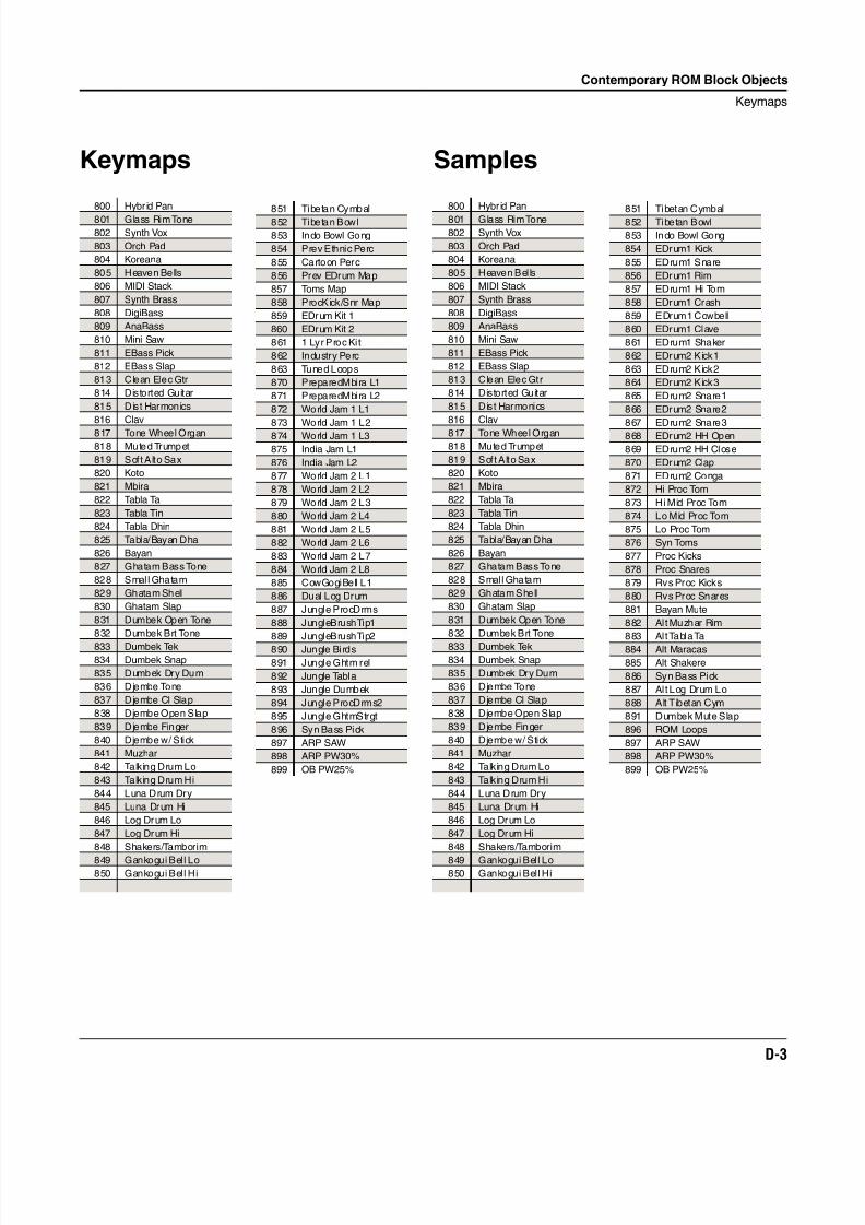
8/21/2019 MR_K2661
http://slidepdf.com/reader/full/mrk2661 425/499
Contemporary ROM Block Objects
Keymaps
D-3
Keymaps
800 Hybr id Pan
801 Glass Rim Tone
802 Synth Vox
803 Orch Pad
804 Koreana
805 Heaven Bells
806 MIDI Stack
807 Synth Brass
808 DigiBass
809 AnaBass
810 Mini Saw
811 EBass Pick
812 EBass Slap
813 Clean Elec Gtr
814 Distorted Guitar
815 Dist Harmonics
816 Clav
817 Tone Wheel Organ
818 Muted Trumpet
819 Soft Alto Sax
820 Koto
821 Mbira
822 Tabla Ta
823 Tabla Tin
824 Tabla Dhin
825 Tabla/Bayan Dha
826 Bayan
827 Ghatam Bass Tone
828 Smal l Ghatam
829 Ghatam Shell
830 Ghatam Slap
831 Dumbek Open Tone
832 Dumbek Brt Tone
833 Dumbek Tek
834 Dumbek Snap
835 Dumbek Dry Dum
836 Djembe Tone
837 Djembe Cl Slap
838 Djembe Open Slap
839 Djembe Finger
840 Djembe w/ Stick
841 Muzhar
842 Talking Drum Lo
843 Talking Drum Hi
844 Luna Drum Dry
845 Luna Drum Hi
846 Log Drum Lo
847 Log Drum Hi
848 Shakers/Tamborim
849 Gankogui Bell Lo850 Gankogui Bell Hi
851 Tibetan Cymbal
852 Tibetan Bowl
853 Indo Bowl Gong
854 Prev Ethnic Perc
855 Cartoon Perc
856 Prev EDrum Map
857 Toms Map
858 ProcKick/Snr Map
859 EDrum Kit 1
860 EDrum Kit 2
861 1 Lyr Proc Ki t
862 Industry Perc
863 Tuned Loops
870 PreparedMbira L1
871 PreparedMbira L2
872 World Jam 1 L1
873 World Jam 1 L2
874 World Jam 1 L3
875 India Jam L1
876 India Jam L2
877 World Jam 2 L1
878 World Jam 2 L2
879 World Jam 2 L3
880 World Jam 2 L4
881 World Jam 2 L5
882 World Jam 2 L6
883 World Jam 2 L7
884 World Jam 2 L8
885 CowGogiBell L1
886 Dual Log Drum
887 Jungle ProcDrms
888 JungleBrushTip1
889 JungleBrushTip2
890 Jungle Birds
891 Jungle Ghtm rel
892 Jungle Tabla
893 Jungle Dumbek
894 Jungle ProcDrms2
895 Jungle GhtmStrgt
896 Syn Bass Pick
897 ARP SAW
898 ARP PW30%
899 OB PW25%
Samples
800 Hybr id Pan
801 Glass Rim Tone
802 Synth Vox
803 Orch Pad
804 Koreana
805 Heaven Bel ls
806 MIDI Stack
807 Synth Brass
808 DigiBass
809 AnaBass
810 Mini Saw
811 EBass Pick
812 EBass Slap
813 Clean Elec Gtr
814 Distorted Guitar
815 Dist Harmonics
816 Clav
817 Tone Wheel Organ
818 Muted Trumpet
819 Soft Alto Sax
820 Koto
821 Mbira
822 Tabla Ta
823 Tabla Tin
824 Tabla Dhin
825 Tabla/Bayan Dha
826 Bayan
827 Ghatam Bass Tone
828 Smal l Ghatam
829 Ghatam Shell
830 Ghatam Slap
831 Dumbek Open Tone
832 Dumbek Brt Tone
833 Dumbek Tek
834 Dumbek Snap
835 Dumbek Dry Dum
836 Djembe Tone
837 Djembe Cl Slap
838 Djembe Open Slap
839 Djembe Finger
840 Djembe w/ Stick
841 Muzhar
842 Talking Drum Lo
843 Talking Drum Hi
844 Luna Drum Dry
845 Luna Drum Hi
846 Log Drum Lo
847 Log Drum Hi
848 Shakers/Tamborim
849 Gankogui Bell Lo850 Gankogui Bell Hi
851 Tibetan Cymbal
852 Tibetan Bowl
853 Indo Bowl Gong
854 EDrum1 Kick
855 EDrum1 Snare
856 EDrum1 Rim
857 EDrum1 Hi Tom
858 EDrum1 Crash
859 EDrum1 Cowbell
860 EDrum1 Clave
861 EDrum1 Shaker
862 EDrum2 Kick1
863 EDrum2 Kick2
864 EDrum2 Kick3
865 EDrum2 Snare1
866 EDrum2 Snare2
867 EDrum2 Snare3
868 EDrum2 HH Open
869 EDrum2 HH Close
870 EDrum2 Clap
871 EDrum2 Conga
872 Hi Proc Tom
873 Hi Mid Proc Tom
874 Lo Mid Proc Tom
875 Lo Proc Tom
876 Syn Toms
877 Proc Kicks
878 Proc Snares
879 Rvs Proc Kicks
880 Rvs Proc Snares
881 Bayan Mute
882 Al t Muzhar Rim
883 Alt Tabla Ta
884 Alt Maracas
885 Alt Shakere
886 Syn Bass Pick
887 Al t Log Drum Lo
888 Alt Tibetan Cym
891 Dumbek Mute Slap
896 ROM Loops
897 ARP SAW
898 ARP PW30%
899 OB PW25%
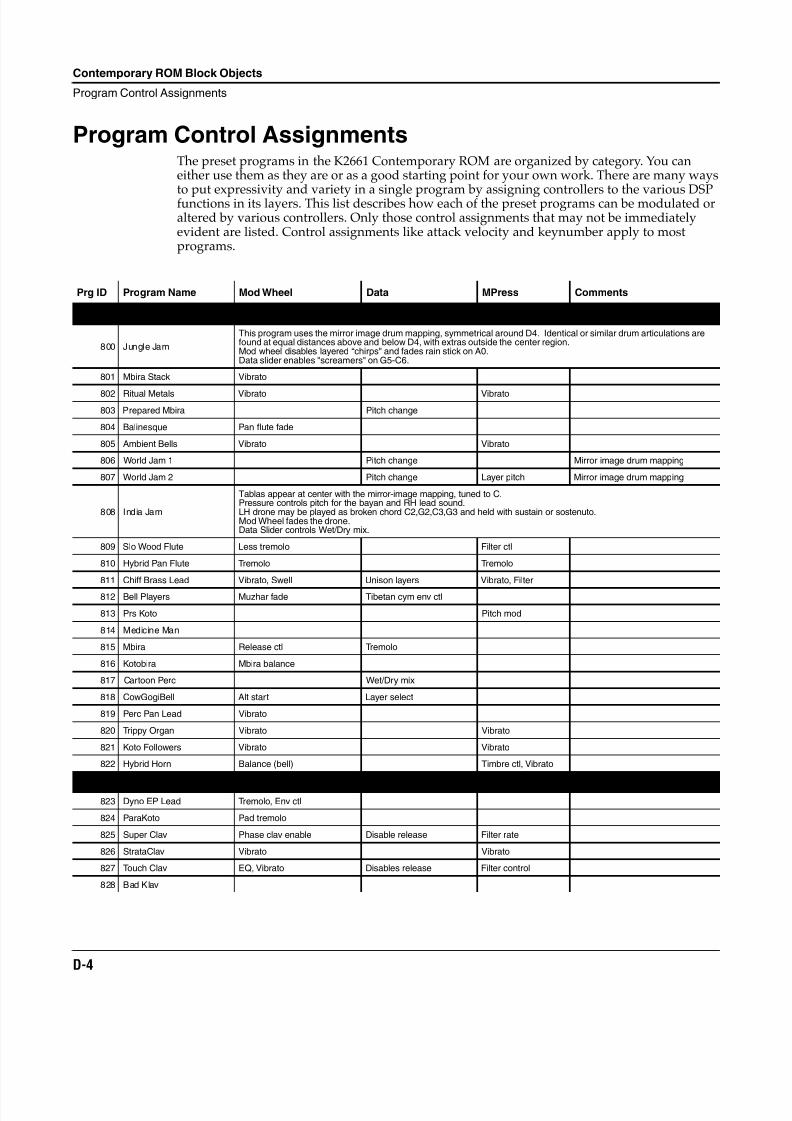
8/21/2019 MR_K2661
http://slidepdf.com/reader/full/mrk2661 426/499
D-4
Contemporary ROM Block Objects
Program Control Assignments
Program Control AssignmentsThe preset programs in the K2661 Contemporary ROM are organized by category. You caneither use them as they are or as a good starting point for your own work. There are many ways
to put expressivity and variety in a single program by assigning controllers to the various DSPfunctions in its layers. This list describes how each of the preset programs can be modulated oraltered by various controllers. Only those control assignments that may not be immediatelyevident are listed. Control assignments like attack velocity and keynumber apply to mostprograms.
Prg ID Program Name Mod Wheel Data MPress Comments
Ethnic / World Instruments
800 Jungle Jam
This program uses the mirror image drum mapping, symmetrical around D4. Identical or similar drum articulations arefound at equal distances above and below D4, with extras outside the center region.Mod wheel disables layered “chirps" and fades rain stick on A0.Data slider enables "screamers" on G5-C6.
801 Mbira Stack Vibrato
802 Ritual Metals Vibrato Vibrato
803 Prepared Mbira Pitch change
804 Balinesque Pan flute fade
805 Ambient Bells Vibrato Vibrato
806 World Jam 1 Pitch change Mirror image drum mapping
807 World Jam 2 Pitch change Layer pitch Mirror image drum mapping
808 India Jam
Tablas appear at center with the mirror-image mapping, tuned to C.Pressure controls pitch for the bayan and RH lead sound.LH drone may be played as broken chord C2,G2,C3,G3 and held with sustain or sostenuto.Mod Wheel fades the drone.Data Slider controls Wet/Dry mix.
809 Slo Wood Flute Less tremolo Filter ctl
810 Hybrid Pan Flute Tremolo Tremolo
811 Chiff Brass Lead Vibrato, Swell Unison layers Vibrato, Filter
812 Bell Players Muzhar fade Tibetan cym env ctl
813 Prs Koto Pitch mod
814 Medicine Man
815 Mbira Release ctl Tremolo
816 Kotobira Mbira balance
817 Cartoon Perc Wet/Dry mix
818 CowGogiBell Alt start Layer select
819 Perc Pan Lead Vibrato
820 Trippy Organ Vibrato Vibrato
821 Koto Followers Vibrato Vibrato
822 Hybrid Horn Balance (bell) Timbre ctl, Vibrato
Keyboards823 Dyno EP Lead Tremolo, Env ctl
824 ParaKoto Pad tremolo
825 Super Clav Phase clav enable Disable release Filter rate
826 StrataClav Vibrato Vibrato
827 Touch Clav EQ, Vibrato Disables release Filter control
828 Bad Klav
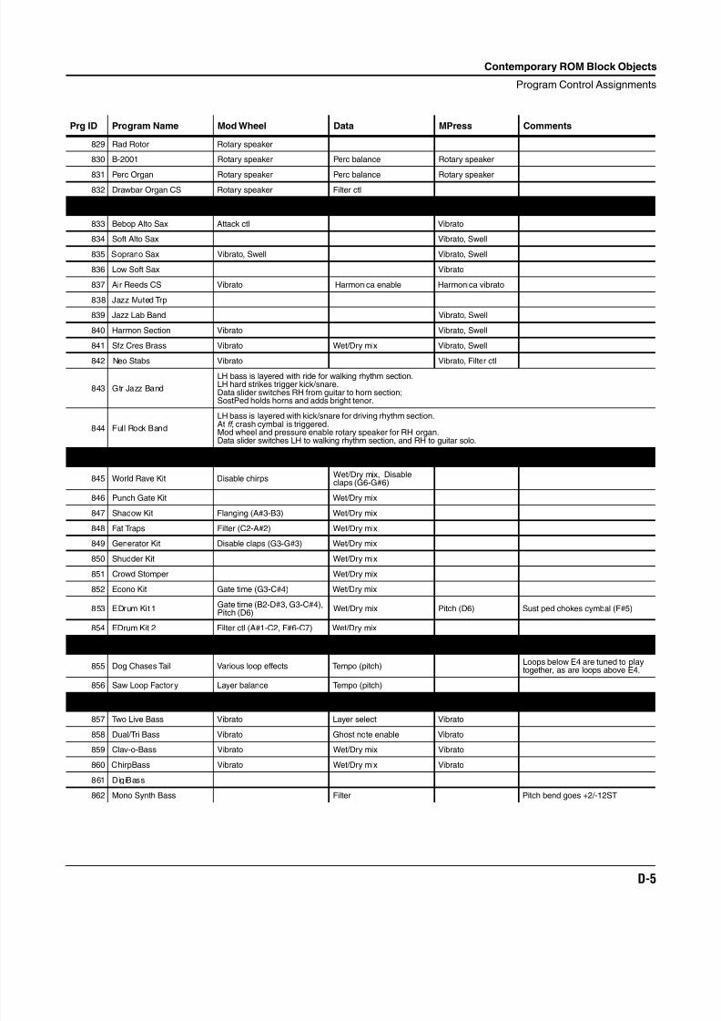
8/21/2019 MR_K2661
http://slidepdf.com/reader/full/mrk2661 427/499
Contemporary ROM Block Objects
Program Control Assignments
D-5
829 Rad Rotor Rotary speaker
830 B-2001 Rotary speaker Perc balance Rotary speaker
831 Perc Organ Rotary speaker Perc balance Rotary speaker832 Drawbar Organ CS Rotary speaker Filter ctl
Brass and Reeds
833 Bebop Alto Sax Attack ctl Vibrato
834 Soft Alto Sax Vibrato, Swell
835 Soprano Sax Vibrato, Swell Vibrato, Swell
836 Low Soft Sax Vibrato
837 Air Reeds CS Vibrato Harmonica enable Harmonica vibrato
838 Jazz Muted Trp
839 Jazz Lab Band Vibrato, Swell
840 Harmon Section Vibrato Vibrato, Swell
841 Sfz Cres Brass Vibrato Wet/Dry mix Vibrato, Swell
842 Neo Stabs Vibrato Vibrato, Filter ctl
843 Gtr Jazz Band
LH bass is layered with ride for walking rhythm section.LH hard strikes trigger kick/snare.Data slider switches RH from guitar to horn section;SostPed holds horns and adds bright tenor.
844 Full Rock Band
LH bass is layered with kick/snare for driving rhythm section.At ff , crash cymbal is triggered.Mod wheel and pressure enable rotary speaker for RH organ.Data slider switches LH to walking rhythm section, and RH to guitar solo.
Drum Kits
845 World Rave Kit Disable chirpsWet/Dry mix, Disableclaps (G6-G#6)
846 Punch Gate Kit Wet/Dry mix
847 Shadow Kit Flanging (A#3-B3) Wet/Dry mix
848 Fat Traps Filter (C2-A#2) Wet/Dry mix
849 Generator Kit Disable claps (G3-G#3) Wet/Dry mix
850 Shudder Kit Wet/Dry mix
851 Crowd Stomper Wet/Dry mix
852 Econo Kit Gate time (G3-C#4) Wet/Dry mix
853 EDrum Kit 1Gate time (B2-D#3, G3-C#4),Pitch (D6)
Wet/Dry mix Pitch (D6) Sust ped chokes cymbal (F#5)
854 EDrum Kit 2 Filter ctl (A#1-C2, F#6-C7) Wet/Dry mix
Loops
855 Dog Chases Tail Various loop effects Tempo (pitch)Loops below E4 are tuned to playtogether, as are loops above E4.
856 Saw Loop Factory Layer balance Tempo (pitch)
Basses
857 Two Live Bass Vibrato Layer select Vibrato
858 Dual/Tri Bass Vibrato Ghost note enable Vibrato
859 Clav-o-Bass Vibrato Wet/Dry mix Vibrato
860 ChirpBass Vibrato Wet/Dry mix Vibrato
861 DigiBass
862 Mono Synth Bass Filter Pitch bend goes +2/-12ST
Prg ID Program Name Mod Wheel Data MPress Comments
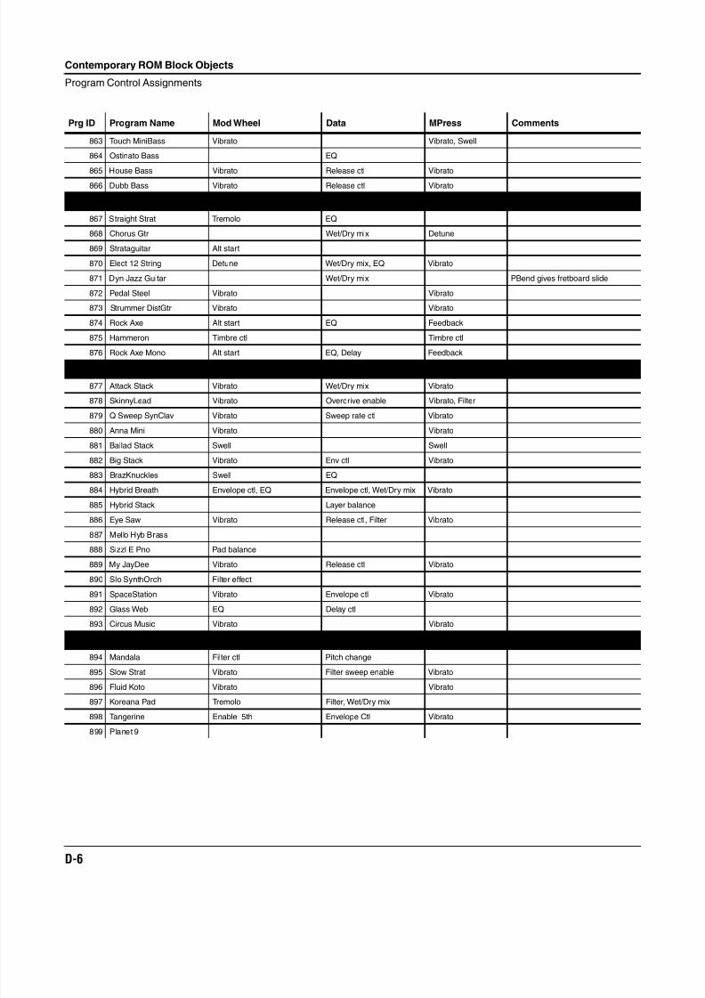
8/21/2019 MR_K2661
http://slidepdf.com/reader/full/mrk2661 428/499
D-6
Contemporary ROM Block Objects
Program Control Assignments
863 Touch MiniBass Vibrato Vibrato, Swell
864 Ostinato Bass EQ
865 House Bass Vibrato Release ctl Vibrato866 Dubb Bass Vibrato Release ctl Vibrato
Guitars
867 Straight Strat Tremolo EQ
868 Chorus Gtr Wet/Dry mix Detune
869 Strataguitar Alt start
870 Elect 12 String Detune Wet/Dry mix, EQ Vibrato
871 Dyn Jazz Guitar Wet/Dry mix PBend gives fretboard slide
872 Pedal Steel Vibrato Vibrato
873 Strummer DistGtr Vibrato Vibrato
874 Rock Axe Alt start EQ Feedback
875 Hammeron Timbre ctl Timbre ctl
876 Rock Axe Mono Alt start EQ, Delay Feedback
Synth Timbres
877 Attack Stack Vibrato Wet/Dry mix Vibrato
878 SkinnyLead Vibrato Overdrive enable Vibrato, Filter
879 Q Sweep SynClav Vibrato Sweep rate ctl Vibrato
880 Anna Mini Vibrato Vibrato
881 Ballad Stack Swell Swell
882 Big Stack Vibrato Env ctl Vibrato
883 BrazKnuckles Swell EQ
884 Hybrid Breath Envelope ctl, EQ Envelope ctl, Wet/Dry mix Vibrato
885 Hybrid Stack Layer balance
886 Eye Saw Vibrato Release ctl, Filter Vibrato
887 Mello Hyb Brass
888 Sizzl E Pno Pad balance
889 My JayDee Vibrato Release ctl Vibrato
890 Slo SynthOrch Filter effect
891 SpaceStation Vibrato Envelope ctl Vibrato
892 Glass Web EQ Delay ctl
893 Circus Music Vibrato Vibrato
Pads
894 Mandala Filter ctl Pitch change
895 Slow Strat Vibrato Filter sweep enable Vibrato
896 Fluid Koto Vibrato Vibrato
897 Koreana Pad Tremolo Filter, Wet/Dry mix
898 Tangerine Enable 5th Envelope Ctl Vibrato
899 Planet 9
Prg ID Program Name Mod Wheel Data MPress Comments
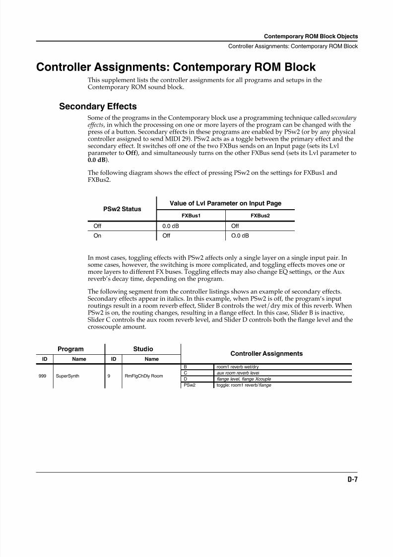
8/21/2019 MR_K2661
http://slidepdf.com/reader/full/mrk2661 429/499
Contemporary ROM Block Objects
Controller Assignments: Contemporary ROM Block
D-7
Controller Assignments: Contemporary ROM Block This supplement lists the controller assignments for all programs and setups in theContemporary ROM sound block.
Secondary EffectsSome of the programs in the Contemporary block use a programming technique called secondaryeffects , in which the processing on one or more layers of the program can be changed with thepress of a button. Secondary effects in these programs are enabled by PSw2 (or by any physicalcontroller assigned to send MIDI 29). PSw2 acts as a toggle between the primary effect and thesecondary effect. It switches off one of the two FXBus sends on an Input page (sets its Lvlparameter to Off), and simultaneously turns on the other FXBus send (sets its Lvl parameter to0.0 dB).
The following diagram shows the effect of pressing PSw2 on the settings for FXBus1 andFXBus2.
In most cases, toggling effects with PSw2 affects only a single layer on a single input pair. Insome cases, however, the switching is more complicated, and toggling effects moves one ormore layers to different FX buses. Toggling effects may also change EQ settings, or the Auxreverb’s decay time, depending on the program.
The following segment from the controller listings shows an example of secondary effects.Secondary effects appear in italics. In this example, when PSw2 is off, the program’s inputroutings result in a room reverb effect, Slider B controls the wet/dry mix of this reverb. WhenPSw2 is on, the routing changes, resulting in a flange effect. In this case, Slider B is inactive,Slider C controls the aux room reverb level, and Slider D controls both the flange level and thecrosscouple amount.
PSw2 StatusValue of Lvl Parameter on Input Page
FXBus1 FXBus2
Off 0.0 dB Off
On Off O.0 dB
Program StudioController Assignments
ID Name ID Name
999 SuperSynth 9 RmFlgChDly Room
B room1 reverb wet/dry
C aux room reverb level
D flange level, flange Xcouple
PSw2 toggle: room1 reverb/ flange
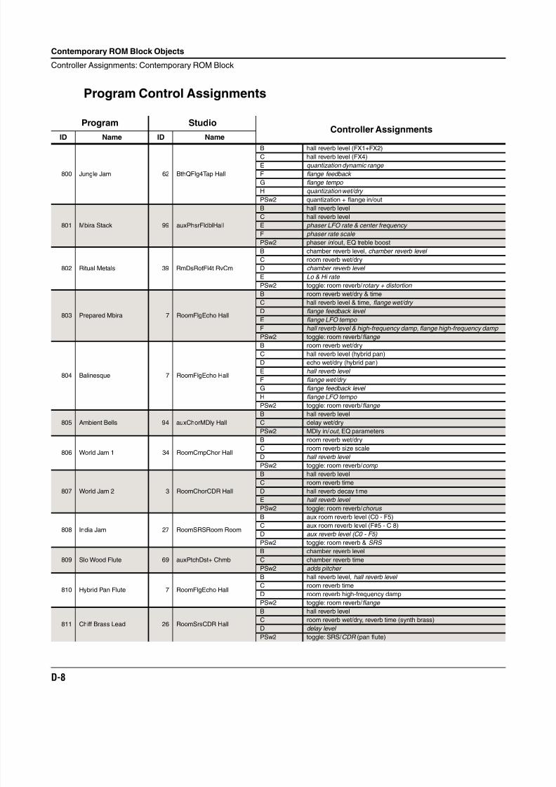
8/21/2019 MR_K2661
http://slidepdf.com/reader/full/mrk2661 430/499
D-8
Contemporary ROM Block Objects
Controller Assignments: Contemporary ROM Block
Program Control Assignments
Program StudioController Assignments
ID Name ID Name
800 Jungle Jam 62 BthQFlg4Tap Hall
B hall reverb level (FX1+FX2)
C hall reverb level (FX4)
E quantization dynamic range
F flange feedback
G flange tempo
H quantization wet/dry
PSw2 quantization + flange in/out
801 Mbira Stack 99 auxPhsrFldblHall
B hall reverb level
C hall reverb level
E phaser LFO rate & center frequency
F phaser rate scale
PSw2 phaser in /out, EQ treble boost
802 Ritual Metals 39 RmDsRotFl4t RvCm
B chamber reverb level, chamber reverb level
C room reverb wet/dry
D chamber reverb level
E Lo & Hi rate PSw2 toggle: room reverb/ rotary + distortion
803 Prepared Mbira 7 RoomFlgEcho Hall
B room reverb wet/dry & time
C hall reverb level & time, flange wet/dry
D flange feedback level
E flange LFO tempo
F hall reverb level & high-frequency damp, flange high-frequency damp
PSw2 toggle: room reverb/ flange
804 Balinesque 7 RoomFlgEcho Hall
B room reverb wet/dry
C hall reverb level (hybrid pan)
D echo wet/dry (hybrid pan)
E hall reverb level
F flange wet/dry
G flange feedback level
H flange LFO tempo
PSw2 toggle: room reverb/ flange
805 Ambient Bells 94 auxChorMDly HallB hall reverb levelC delay wet/dry
PSw2 MDly in/ out , EQ parameters
806 World Jam 1 34 RoomCmpChor Hall
B room reverb wet/dry
C room reverb size scale
D hall reverb level
PSw2 toggle: room reverb/ comp
807 World Jam 2 3 RoomChorCDR Hall
B hall reverb level
C room reverb time
D hall reverb decay time
E hall reverb level
PSw2 toggle: room reverb/ chorus
808 India Jam 27 RoomSRSRoom Room
B aux room reverb level (C0 - F5)
C aux room reverb level (F#5 - C 8)
D aux reverb level (C0 - F5)
PSw2 toggle: room reverb & SRS
809 Slo Wood Flute 69 auxPtchDst+ ChmbB chamber reverb levelC chamber reverb time
PSw2 adds pitcher
810 Hybrid Pan Flute 7 RoomFlgEcho Hall
B hall reverb level, hall reverb level
C room reverb time
D room reverb high-frequency damp
PSw2 toggle: room reverb/ flange
811 Chiff Brass Lead 26 RoomSrsCDR Hall
B hall reverb level
C room reverb wet/dry, reverb time (synth brass)
D delay level
PSw2 toggle: SRS/ CDR (pan flute)
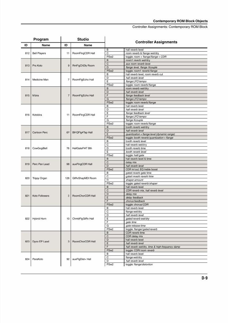
8/21/2019 MR_K2661
http://slidepdf.com/reader/full/mrk2661 431/499
Contemporary ROM Block Objects
Controller Assignments: Contemporary ROM Block
D-9
812 Bell Players 11 RoomFlngCDR Hall
B hall reverb level
C room reverb & flange wet/dry
PSw2 toggle: room + flange/ flange + CDR
813 Prs Koto 9 RmFlgChDly Room
B room1 reverb wet/dry
C aux room reverb level
D flange level, flange Xcouple
PSw2 toggle: room1 reverb/ flange
814 Medicine Man 7 RoomFlgEcho Hall
B hall reverb level, room reverb cut
D hall reverb level
E flange LFO tempo
PSw2 toggle: room reverb/ flange
815 Mbira 7 RoomFlgEcho Hall
B room reverb wet/dry
D hall reverb level
F flange feedback level
G flange LFO tempo
PSw2 toggle: room reverb/ flange
816 Kotobira 11 RoomFlngCDR Hall
B hall reverb level
D hall reverb level
E flange feedback level F flange LFO tempo
G flange Xcouple
PSw2 toggle: room reverb/ flange
817 Cartoon Perc 62 BthQFlg4Tap Hall
B booth reverb wet/dry
D hall reverb level
E quantization + flange level (dynamic range)
PSw2 toggle: booth reverb/ quantization + flange
818 CowGogiBell 76 HallGateFl4T Bth
B booth reverb level
C hall reverb wet/dry
D booth reverb time
E booth reverb level
PSw2 toggle: hall/ gate
819 Perc Pan Lead 98 auxFlngCDR Hall
B hall reverb level & time
C delay mix
D hall reverb level
PSw2 CDR in/ out , EQ treble boost
820 Trippy Organ 126 GtRvShapMDl Room
B gated reverb gate time
C gated reverb reverb time
D shaper amount
PSw2 toggle: gated reverb/ shaper
821 Koto Followers 3 RoomChorCDR Hall
B hall reverb level
C CDR reverb mix, hall reverb level
D delay mix
E delay feedback
F chorus feedback
PSw2 toggle: chorus/ CDR
822 Hybrid Horn 10 ChmbFlgGtRv Hall
B hall reverb level
C flange wet/dry
D hall reverb level
E gated reverb wet/dry
F gate time
G gate release time PSw2 toggle: flanger/ gated reverb
823 Dyno EP Lead 3 RoomChorCDR Hall
B CDR reverb time
C CDR delay mix
D hall reverb level
E hall reverb level
F hall reverb wet/dry, time & high-frequency damp
PSw2 toggle: CDR/ room reverb
824 ParaKoto 92 auxFlgDist+ Hall
B hall reverb level
C flange wet/dry
D hall reverb level
PSw2 toggle: flange/ distortion
Program StudioController Assignments
ID Name ID Name
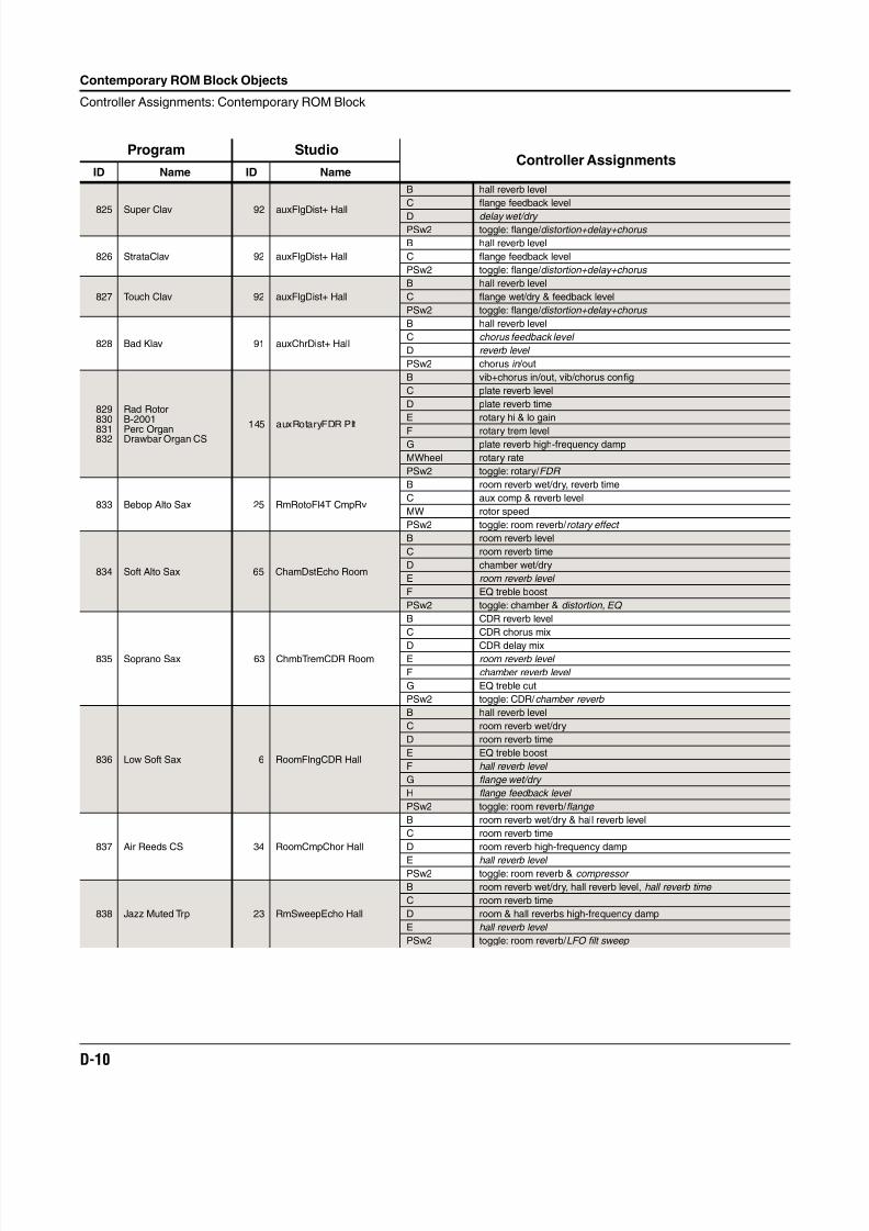
8/21/2019 MR_K2661
http://slidepdf.com/reader/full/mrk2661 432/499
D-10
Contemporary ROM Block Objects
Controller Assignments: Contemporary ROM Block
825 Super Clav 92 auxFlgDist+ Hall
B hall reverb level
C flange feedback level
D delay wet/dry PSw2 toggle: flange/ distortion+delay+chorus
826 StrataClav 92 auxFlgDist+ Hall
B hall reverb level
C flange feedback level
PSw2 toggle: flange/ distortion+delay+chorus
827 Touch Clav 92 auxFlgDist+ Hall
B hall reverb level
C flange wet/dry & feedback level
PSw2 toggle: flange/ distortion+delay+chorus
828 Bad Klav 91 auxChrDist+ Hall
B hall reverb level
C chorus feedback level
D reverb level
PSw2 chorus in /out
829830
831832
Rad RotorB-2001
Perc OrganDrawbar Organ CS
145 auxRotaryFDR Plt
B vib+chorus in/out, vib/chorus config
C plate reverb level
D plate reverb time
E rotary hi & lo gain
F rotary trem levelG plate reverb high-frequency damp
MWheel rotary rate
PSw2 toggle: rotary/ FDR
833 Bebop Alto Sax 25 RmRotoFl4T CmpRv
B room reverb wet/dry, reverb time
C aux comp & reverb level
MW rotor speed
PSw2 toggle: room reverb/ rotary effect
834 Soft Alto Sax 65 ChamDstEcho Room
B room reverb level
C room reverb time
D chamber wet/dry
E room reverb level
F EQ treble boost
PSw2 toggle: chamber & distortion, EQ
835 Soprano Sax 63 ChmbTremCDR Room
B CDR reverb level
C CDR chorus mix
D CDR delay mixE room reverb level
F chamber reverb level
G EQ treble cut
PSw2 toggle: CDR/ chamber reverb
836 Low Soft Sax 6 RoomFlngCDR Hall
B hall reverb level
C room reverb wet/dry
D room reverb time
E EQ treble boost
F hall reverb level
G flange wet/dry
H flange feedback level
PSw2 toggle: room reverb/ flange
837 Air Reeds CS 34 RoomCmpChor Hall
B room reverb wet/dry & hall reverb level
C room reverb time
D room reverb high-frequency damp
E hall reverb level PSw2 toggle: room reverb & compressor
838 Jazz Muted Trp 23 RmSweepEcho Hall
B room reverb wet/dry, hall reverb level, hall reverb time
C room reverb time
D room & hall reverbs high-frequency damp
E hall reverb level
PSw2 toggle: room reverb/ LFO filt sweep
Program StudioController Assignments
ID Name ID Name
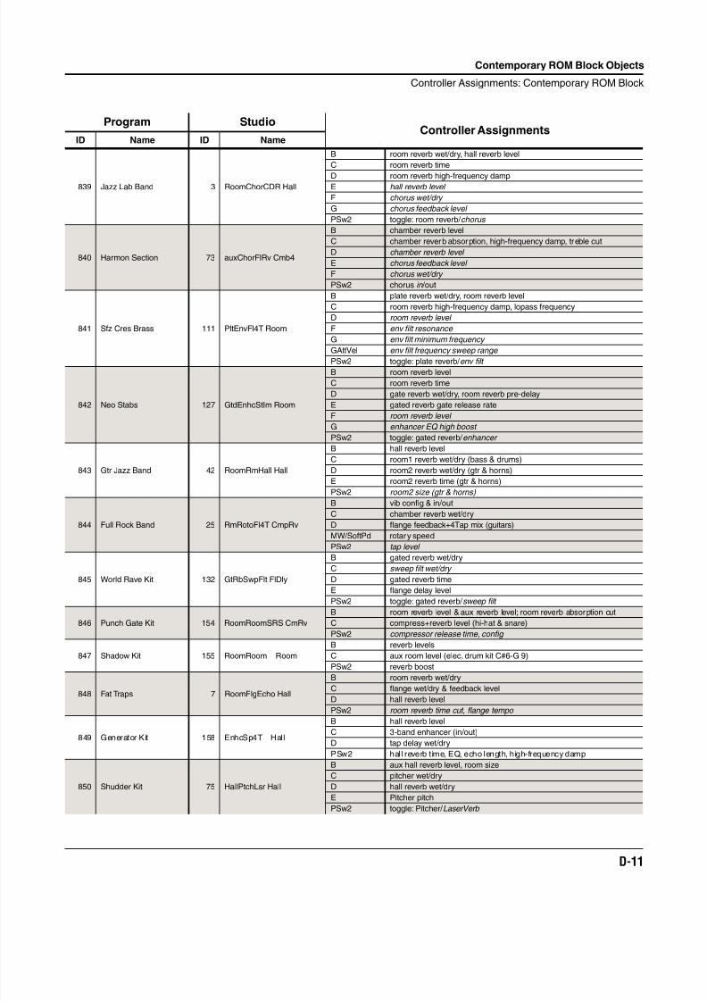
8/21/2019 MR_K2661
http://slidepdf.com/reader/full/mrk2661 433/499
Contemporary ROM Block Objects
Controller Assignments: Contemporary ROM Block
D-11
839 Jazz Lab Band 3 RoomChorCDR Hall
B room reverb wet/dry, hall reverb level
C room reverb time
D room reverb high-frequency dampE hall reverb level
F chorus wet/dry
G chorus feedback level
PSw2 toggle: room reverb/ chorus
840 Harmon Section 73 auxChorFlRv Cmb4
B chamber reverb level
C chamber reverb absorption, high-frequency damp, treble cut
D chamber reverb level
E chorus feedback level
F chorus wet/dry
PSw2 chorus in /out
841 Sfz Cres Brass 111 PltEnvFl4T Room
B plate reverb wet/dry, room reverb level
C room reverb high-frequency damp, lopass frequency
D room reverb level
F env filt resonance
G env filt minimum frequency
GAttVel env filt frequency sweep range PSw2 toggle: plate reverb/ env filt
842 Neo Stabs 127 GtdEnhcStIm Room
B room reverb level
C room reverb time
D gate reverb wet/dry, room reverb pre-delay
E gated reverb gate release rate
F room reverb level
G enhancer EQ high boost
PSw2 toggle: gated reverb/ enhancer
843 Gtr Jazz Band 42 RoomRmHall Hall
B hall reverb level
C room1 reverb wet/dry (bass & drums)
D room2 reverb wet/dry (gtr & horns)
E room2 reverb time (gtr & horns)
PSw2 room2 size (gtr & horns)
844 Full Rock Band 25 RmRotoFl4T CmpRv
B vib config & in/out
C chamber reverb wet/dry
D flange feedback+4Tap mix (guitars)MW/SoftPd rotary speed
PSw2 tap level
845 World Rave Kit 132 GtRbSwpFlt FlDly
B gated reverb wet/dry
C sweep filt wet/dry
D gated reverb time
E flange delay level
PSw2 toggle: gated reverb/ sweep filt
846 Punch Gate Kit 154 RoomRoomSRS CmRv
B room reverb level & aux reverb level; room reverb absorption cut
C compress+reverb level (hi-hat & snare)
PSw2 compressor release time, config
847 Shadow Kit 155 RoomRoom Room
B reverb levels
C aux room level (elec. drum kit C#6-G 9)
PSw2 reverb boost
848 Fat Traps 7 RoomFlgEcho Hall
B room reverb wet/dry
C flange wet/dry & feedback level
D hall reverb levelPSw2 room reverb time cut, flange tempo
849 Generator Kit 158 EnhcSp4T Hall
B hall reverb level
C 3-band enhancer (in/out)
D tap delay wet/dry
PSw2 hall reverb t ime, EQ, echo length, high-frequency damp
850 Shudder Kit 75 HallPtchLsr Hall
B aux hall reverb level, room size
C pitcher wet/dry
D hall reverb wet/dry
E Pitcher pitch
PSw2 toggle: Pitcher/ LaserVerb
Program StudioController Assignments
ID Name ID Name
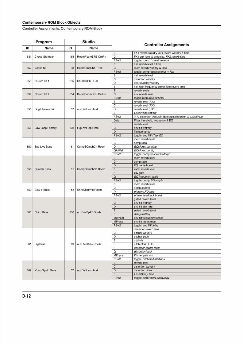
8/21/2019 MR_K2661
http://slidepdf.com/reader/full/mrk2661 434/499
D-12
Contemporary ROM Block Objects
Controller Assignments: Contemporary ROM Block
851 Crowd Stomper 154 RoomRoomSRS CmRv
B FX1 reverb wet/dry, aux reverb wet/dry & time
C FX1 aux level & predelay, FX2 reverb time
PSw2 toggle: room1/ room2 reverbs
852 Econo Kit 38 RoomCmpCh4T Hall
B hall reverb level & time
C room reverb wet/dry & time
PSw2 toggle: compressor/ chorus+4Tap
853 EDrum Kit 1 135 ChDlDstEQ Hall
B hall reverb level
C distortion wet/dry
D chorus/delay wet/dry
E hall high-frequency damp, late reverb time
854 EDrum Kit 2 154 RoomRoomSRS CmRv
B reverb levels
C aux reverb level
PSw2 toggle room reverb/ SRS
855 Dog Chases Tail 57 auxDistLasr Acid
B reverb level (FX2)
C reverb level (FX3)
D reverb level (FX1)
E LaserVerb wet/dry
PSw2 in A: distortion in /out; in B: toggle: distortion & LaserVerb
856 Saw Loop Factory 123 FlgEnv4Tap Plate
Data Filter threshold, frequency & EQB reverb level
C env filt wet/dry
D filt resonance
PSw2 toggle: env filt/ 4Tap, EQ
857 Two Live Bass 61 CompEQmphCh Room
B room reverb level
C comp ratio
D EQMorph panning
GAttVel EQMorph config
PSw2 toggle: compressor/ EQMorph
858 Dual/Tri Bass 61 CompEQmphCh Room
B room reverb level
C comp ratio
D EQ treble boost
E room reverb level
F EQ gain
G EQ frequency scale
PSw2 toggle: comp/ EQmorph
859 Clav-o-Bass 58 EnhcManPhs Room
B room reverb level
C notch control
D phaser LFO rate
PSw2 phaser feedback boost
860 Chirp Bass 130 auxEnvSp4T GtVrb
B gated reverb level
C env filt wet/dry
D env filt attk rate
E gated reverb level
F delay wet/dry
MWheel env filt frequency sweep
MPress env filt resonance
PSw2 toggle: env filt/ delay
861 DigiBass 69 auxPtchDst+ Chmb
B chamber reverb level
C pitcher wet/dry
D pitcher pitch
E odd wtsF pitch offset LFO
F chamber reverb level
G distortion level
MPress Pitcher pair wts.
PSw2 toggle: pitcher/ distortion+
862 Mono Synth Bass 57 auxDistLasr Acid
B reverb level
C distortion wet/dry
D distortion drive
E LaserDelay time
PSw2 toggle: distortion/ LaserDelay
Program StudioController Assignments
ID Name ID Name
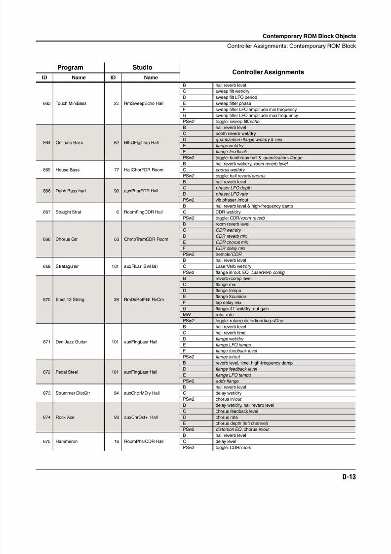
8/21/2019 MR_K2661
http://slidepdf.com/reader/full/mrk2661 435/499
Contemporary ROM Block Objects
Controller Assignments: Contemporary ROM Block
D-13
863 Touch MiniBass 23 RmSweepEcho Hall
B hall reverb level
C sweep filt wet/dry
D sweep filt LFO periodE sweep filter phase
F sweep filter LFO amplitude min frequency
G sweep filter LFO amplitude max frequency
PSw2 toggle: sweep filt/ echo
864 Ostinato Bass 62 BthQFlg4Tap Hall
B hall reverb level
C booth reverb wet/dry
D quantization+flange wet/dry & mix
E flange wet/dry
F flange feedback
PSw2 toggle: booth/aux hall & quantization+flange
865 House Bass 77 HallChorFDR Room
B hall reverb wet/dry, room reverb level
C chorus wet/dry
PSw2 toggle: hall reverb/ chorus
866 Dubb Bass bad 90 auxPhsrFDR Hall
B hall reverb level
C phaser LFO depth
D phaser LFO rate PSw2 vib phaser in /out
867 Straight Strat 6 RoomFlngCDR Hall
B hall reverb level & high-frequency damp
C CDR wet/dry
PSw2 toggle: CDR/ room reverb
868 Chorus Gtr 63 ChmbTremCDR Room
B room reverb level
C CDR wet/dry
D CDR reverb mix
E CDR chorus mix
F CDR delay mix
PSw2 tremolo/ CDR
869 Strataguitar 101 auxFlLsr SwHall
B hall reverb level
C LaserVerb wet/dry
PSw2 flange in/ out , EQ, LaserVerb config
870 Elect 12 String 39 RmDsRotFl4t RvCm
B reverb+comp level
C flange mix
D flange tempoE flange Xcursion
F tap delay mix
G flange+4T wet/dry, out gain
MW rotor rate
PSw2 toggle: rotary+distortion/ flng+4Tap
871 Dyn Jazz Guitar 101 auxFlngLasr Hall
B hall reverb level
C hall reverb time
D flange wet/dry
E flange LFO tempo
F flange feedback level
PSw2 flange in/out
872 Pedal Steel 101 auxFlngLasr Hall
B reverb level, time, high-frequency damp
D flange feedback level
E flange LFO tempo
PSw2 adds flange
873 Strummer DistGtr 94 auxChorMDly HallB hall reverb levelC delay wet/dry
PSw2 chorus in/ out
874 Rock Axe 93 auxChrDst+ Hall
B delay wet/dry, hall reverb level
C chorus feedback level
D chorus rate
E chorus depth (left channel)
PSw2 distortion EQ , chorus in /out
875 Hammeron 16 RoomPhsrCDR Hall
B hall reverb level
C delay level
PSw2 toggle: CDR/ room
Program StudioController Assignments
ID Name ID Name
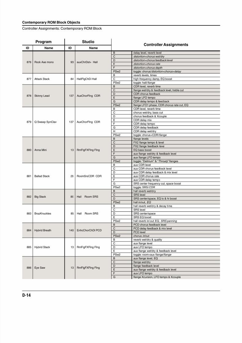
8/21/2019 MR_K2661
http://slidepdf.com/reader/full/mrk2661 436/499
D-14
Contemporary ROM Block Objects
Controller Assignments: Contemporary ROM Block
876 Rock Axe mono 93 auxChrDst+ Hall
B delay level, reverb level
C distortion+chorus wet/dry
D distortion+chorus feedback level E distortion+chorus rate
F distortion+chorus depth
PSw2 toggle: chorus/ distortion+chorus+delay
877 Attack Stack 84 HallFlgChDl Hall
B reverb levels, times
C high-frequency damp, EQ boost
PSw2 toggle: hall/ flange
878 Skinny Lead 137 AuxChorFlng CDR
B CDR level, reverb time
C flange wet/dry & feedback level, treble cut
D CDR chorus feedback
E flange LFO tempo
G CDR delay tempo & feedback
PSw2 flange LFO1 phase, CDR chorus rate cut, EQ
879 Q Sweep SynClav 137 AuxChorFlng CDR
B CDR level, reverb time
C chorus wet/dry, bass cut
D chorus feedback & Xcouple
E CDR delay mixF CDR delay tempo
G CDR delay feedback
H CDR delay wet/dry
PSw2 toggle: chorus+CDR/ flange
880 Anna Mini 13 RmFlgFXFlng Flng
B flange levels
C FX2 flange tempo & level
D FX2 flange feedback level
E EQ bass boost
F aux flange wet/dry & feedback level
G aux flange LFO tempo
PSw2 toggle: “Delirium” & “Throaty ” flanges
881 Ballad Stack 29 RoomSrsCDR CDR
B aux CDR level
C aux CDR chorus feedback level
D aux CDR delay feedback & mix level
E aux CDR chorus rate
F aux CDR delay tempoG SRS center frequency cut, space boost
PSw2 toggle: SRS/ CDR
882 Big Stack 85 Hall Room SRS
B hall reverb wet/dry
C SRS level
D SRS center/space, EQ lo & hi boost
PSw2 hall in/out, EQ
883 BrazKnuckles 85 Hall Room SRS
B hall reverb wet/dry & decay time
C SRS level
D SRS center/space
E SRS EQ boost
PSw2 hall reverb in/ out , EQ, SRS panning
884 Hybrid Breath 140 EnhcChorChDl PCD
B PCD chorus feedback level
C PCD delay feedback & mix level
D PCD level
PSw2 chorus in /out
885 Hybrid Stack 13 RmFlgFXFlng Flng
B reverb wet/dry & qualityC aux flange level
D aux LFO tempo
E aux flange wet/dry & feedback level
PSw2 toggle: room+aux flange/ flange
886 Eye Saw 13 RmFlgFXFlng Flng
B aux flange level, EQ
C flange wet/dry
D flange feedback level
E aux flange wet/dry & feedback level
F aux LFO tempo
G flange Xcursion, LFO tempo & Xcouple
Program StudioController Assignments
ID Name ID Name
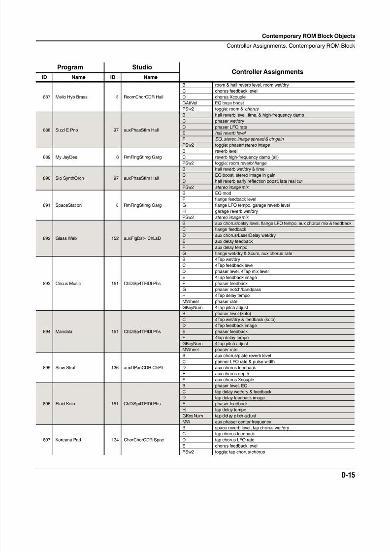
8/21/2019 MR_K2661
http://slidepdf.com/reader/full/mrk2661 437/499
Contemporary ROM Block Objects
Controller Assignments: Contemporary ROM Block
D-15
887 Mello Hyb Brass 3 RoomChorCDR Hall
B room & hall reverb level, room wet/dry
C chorus feedback level
D chorus XcoupleGAttVel EQ bass boost
PSw2 toggle: room & chorus
888 Sizzl E Pno 97 auxPhasStIm Hall
B hall reverb level, time, & high-frequency damp
C phaser wet/dry
D phaser LFO rate
E hall reverb level
F EQ, stereo image spread & ctr gain
PSw2 toggle: phaser/ stereo image
889 My JayDee 8 RmFlngStImg Garg
B reverb level
C reverb high-frequency damp (all)
PSw2 toggle: room reverb/ flange
890 Slo SynthOrch 97 auxPhasStIm Hall
B hall reverb wet/dry & time
C EQ boost, stereo image in gain
D hall reverb early reflection boost, late real cut
PSw2 stereo image mix
891 SpaceStation 8 RmFlngStImg Garg
B EQ modF flange feedback level
G flange LFO tempo, garage reverb level
H garage reverb wet/dry
PSw2 stereo image mix
892 Glass Web 152 auxFlgDst+ ChLsD
B aux chorus/delay level, flange LFO tempo, aux chorus mix & feedback
C flange feedback
D aux chorus/LaserDelay wet/dry
E aux delay feedback
F aux delay tempo
G flange wet/dry & Xcurs, aux chorus rate
893 Circus Music 151 ChDlSp4TFlDl Phs
B 4Tap wet/dry
C 4Tap feedback level
D phaser level, 4Tap mix level
E 4Tap feedback image
F phaser feedback
G phaser notch/bandpassH 4Tap delay tempo
MWheel phaser rate
GKeyNum 4Tap pitch adjust
894 Mandala 151 ChDlSp4TFlDl Phs
B phaser level (koto)
C 4Tap wet/dry & feedback (koto)
D 4Tap feedback image
E phaser feedback
F 4tap delay tempo
GKeyNum 4Tap pitch adjust
MWheel phaser rate
895 Slow Strat 136 auxDPanCDR ChPlt
B aux chorus/plate reverb level
C panner LFO rate & pulse width
D aux chorus feedback
E aux chorus depth
F aux chorus Xcouple
896 Fluid Koto 151 ChDlSp4TFlDl Phs
B phaser level, EQC tap delay wet/dry & feedback
D tap delay feedback image
E phaser feedback
H tap delay tempo
GKeyNum tap delay pitch adjust
MW aux phaser center frequency
897 Koreana Pad 134 ChorChorCDR Spac
B space reverb level, tap chorus wet/dry
C tap chorus feedback
D tap chorus LFO rate
E chorus feedback level
PSw2 toggle: tap chorus/ chorus
Program StudioController Assignments
ID Name ID Name
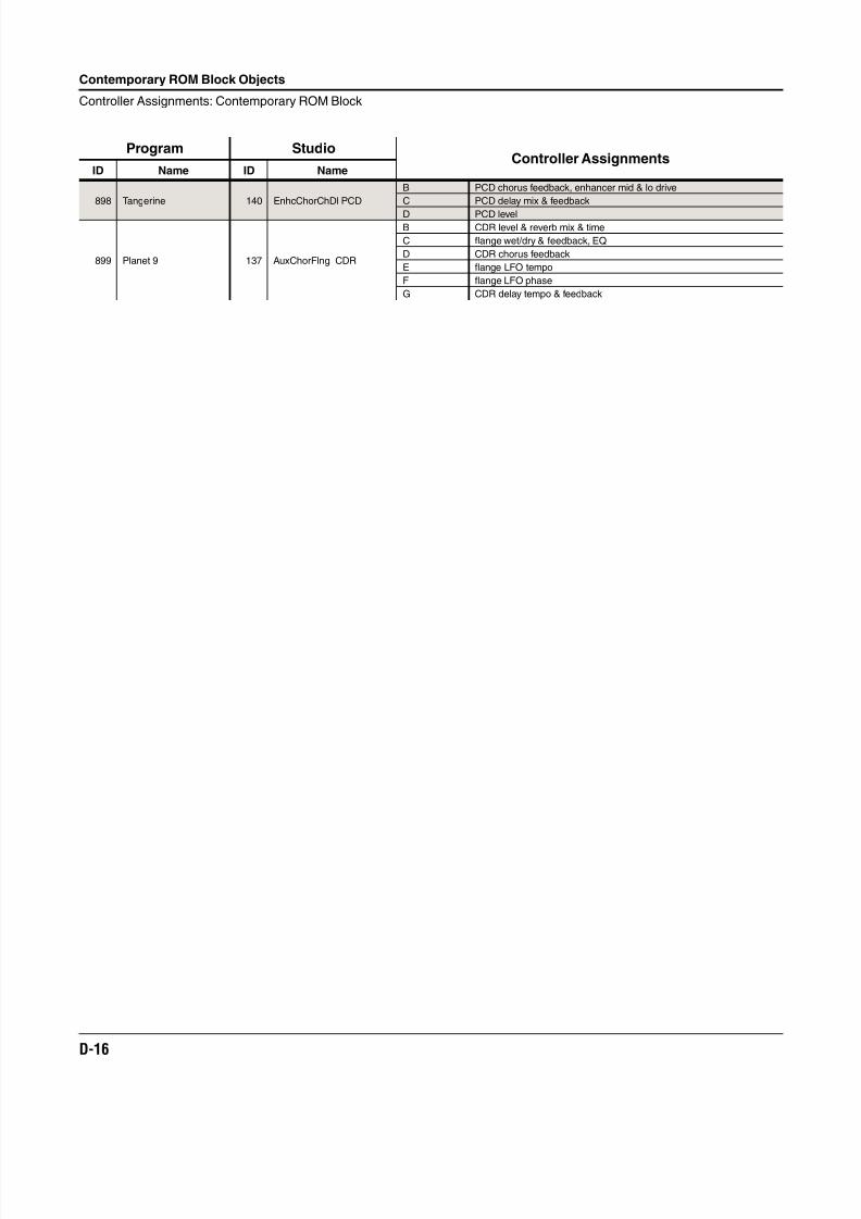
8/21/2019 MR_K2661
http://slidepdf.com/reader/full/mrk2661 438/499
D-16
Contemporary ROM Block Objects
Controller Assignments: Contemporary ROM Block
898 Tangerine 140 EnhcChorChDl PCD
B PCD chorus feedback, enhancer mid & lo drive
C PCD delay mix & feedback
D PCD level
899 Planet 9 137 AuxChorFlng CDR
B CDR level & reverb mix & time
C flange wet/dry & feedback, EQ
D CDR chorus feedback
E flange LFO tempo
F flange LFO phase
G CDR delay tempo & feedback
Program StudioController Assignments
ID Name ID Name
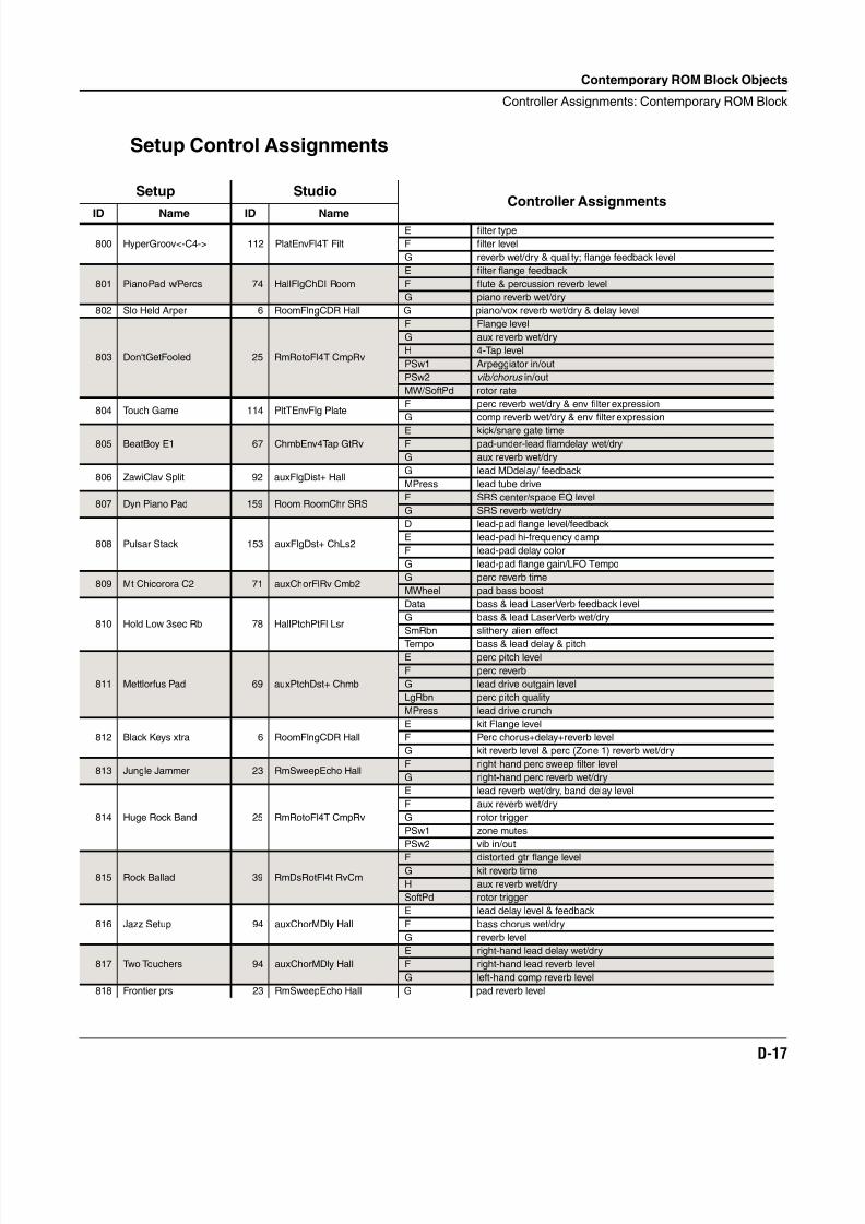
8/21/2019 MR_K2661
http://slidepdf.com/reader/full/mrk2661 439/499
Contemporary ROM Block Objects
Controller Assignments: Contemporary ROM Block
D-17
Setup Control Assignments
Setup StudioController Assignments
ID Name ID Name
800 HyperGroov<-C4-> 112 PlatEnvFl4T Filt
E filter type
F filter level
G reverb wet/dry & quality; flange feedback level
801 PianoPad w/Percs 74 HallFlgChDl Room
E filter flange feedback
F flute & percussion reverb level
G piano reverb wet/dry
802 Slo Held Arper 6 RoomFlngCDR Hall G piano/vox reverb wet/dry & delay level
803 Don'tGetFooled 25 RmRotoFl4T CmpRv
F Flange level
G aux reverb wet/dry
H 4-Tap level
PSw1 Arpeggiator in/out
PSw2 vib/chorus in/out
MW/SoftPd rotor rate
804 Touch Game 114 PltTEnvFlg PlateF perc reverb wet/dry & env filter expression
G comp reverb wet/dry & env filter expression
805 BeatBoy E1 67 ChmbEnv4Tap GtRvE kick/snare gate timeF pad-under-lead flamdelay wet/dry
G aux reverb wet/dry
806 ZawiClav Split 92 auxFlgDist+ HallG lead MDdelay/ feedback
MPress lead tube drive
807 Dyn Piano Pad 159 Room RoomChr SRSF SRS center/space EQ level
G SRS reverb wet/dry
808 Pulsar Stack 153 auxFlgDst+ ChLs2
D lead-pad flange level/feedback
E lead-pad hi-frequency damp
F lead-pad delay color
G lead-pad flange gain/LFO Tempo
809 Mt Chicorora C2 71 auxChorFlRv Cmb2G perc reverb time
MWheel pad bass boost
810 Hold Low 3sec Rb 78 HallPtchPtFl Lsr
Data bass & lead LaserVerb feedback level
G bass & lead LaserVerb wet/dry
SmRbn slithery alien effect
Tempo bass & lead delay & pitch
811 Mettlorfus Pad 69 auxPtchDst+ Chmb
E perc pitch level
F perc reverb
G lead drive outgain level
LgRbn perc pitch quality
MPress lead drive crunch
812 Black Keys xtra 6 RoomFlngCDR Hall
E kit Flange level
F Perc chorus+delay+reverb level
G kit reverb level & perc (Zone 1) reverb wet/dry
813 Jungle Jammer 23 RmSweepEcho HallF right-hand perc sweep filter level
G right-hand perc reverb wet/dry
814 Huge Rock Band 25 RmRotoFl4T CmpRv
E lead reverb wet/dry, band delay level
F aux reverb wet/dry
G rotor trigger
PSw1 zone mutes
PSw2 vib in/out
815 Rock Ballad 39 RmDsRotFl4t RvCm
F distorted gtr flange levelG kit reverb time
H aux reverb wet/dry
SoftPd rotor trigger
816 Jazz Setup 94 auxChorMDly Hall
E lead delay level & feedback
F bass chorus wet/dry
G reverb level
817 Two Touchers 94 auxChorMDly Hall
E right-hand lead delay wet/dry
F right-hand lead reverb level
G left-hand comp reverb level
818 Frontier prs 23 RmSweepEcho Hall G pad reverb level
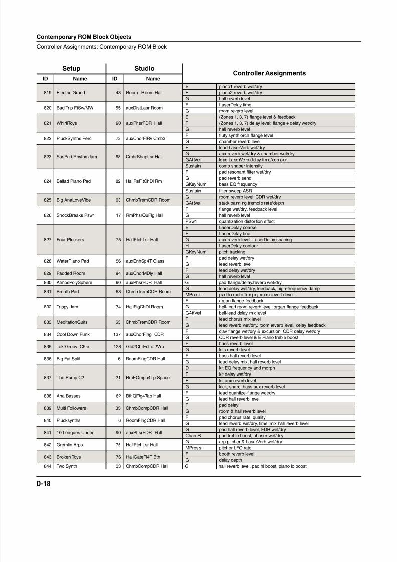
8/21/2019 MR_K2661
http://slidepdf.com/reader/full/mrk2661 440/499
D-18
Contemporary ROM Block Objects
Controller Assignments: Contemporary ROM Block
819 Electric Grand 43 Room Room Hall
E piano1 reverb wet/dry
F piano2 reverb wet/dry
G hall reverb level
820 Bad Trip FtSw/MW 55 auxDistLasr RoomF LaserDelay time
G room reverb level
821 WhirliToys 90 auxPhsrFDR Hall
E (Zones 1, 3, 7) flange level & feedback
F (Zones 1, 3, 7) delay level; flange + delay wet/dry
G hall reverb level
822 PluckSynths Perc 72 auxChorFlRv Cmb3F fluty synth orch flange level
G chamber reverb level
823 SusPed RhythmJam 68 CmbrShapLsr Hall
F lead LaserVerb wet/dry
G aux reverb wet/dry & chamber wet/dry
GAttVel lead LaserVerb delay time/contour
Sustain comp shaper intensity
824 Ballad Piano Pad 82 HallRsFltChDl Rm
F pad resonant filter wet/dry
G pad reverb send
GKeyNum bass EQ frequency
Sustain filter sweep ASR
825 Big AnaLoveVibe 63 ChmbTremCDR Room G room reverb level; CDR wet/dryGAttVel stack panning tremolo rate/depth
826 ShockBreaks Psw1 17 RmPhsrQuFlg Hall
F flange wet/dry, feedback level
G hall reverb level
PSw1 quantization distor tion effect
827 Four Pluckers 75 HallPtchLsr Hall
E LaserDelay coarse
F LaserDelay fine
G aux reverb level; LaserDelay spacing
H LaserDelay contour
GKeyNum pitch tracking
828 WaterPiano Pad 56 auxEnhSp4T ClassF pad delay wet/dry
G lead reverb level
829 Padded Room 94 auxChorMDly HallF lead delay wet/dry
G hall reverb level
830 AtmosPolySphere 90 auxPhsrFDR Hall G pad flange/delay/reverb wet/dry
831 Breath Pad 63 ChmbTremCDR RoomG lead delay wet/dry, feedback, high-frequency damp
MPress pad tremolo Tempo, room reverb level
832 Trippy Jam 74 HallFlgChDl Room
F organ flange feedback
G bell-lead room reverb level; organ flange feedback
GAttVel bell-lead delay mix level
833 MeditationGuits 63 ChmbTremCDR RoomF lead chorus mix level
G lead reverb wet/dry, room reverb level, delay feedback
834 Cool Down Funk 137 auxChorFlng CDRF clav flange wet/dry & excursion; CDR delay wet/dry
G CDR reverb level & E Piano treble boost
835 Tek`Groov C5-> 128 Gtd2ChrEcho 2VrbF bass reverb level
G kits reverb level
836 Big Fat Split 6 RoomFlngCDR HallF bass hall reverb level
G lead delay mix, hall reverb level
837 The Pump C2 21 RmEQmph4Tp Space
D kit EQ frequency and morph
E kit delay wet/dry
F kit aux reverb level
G kick, snare, bass aux reverb level
838 Ana Basses 62 BthQFlg4Tap Hall F lead quantize-flange wet/dryG lead hall reverb level
839 Multi Followers 33 ChmbCompCDR HallF pad delay
G room & hall reverb level
840 Plucksynths 6 RoomFlngCDR HallF pad chorus rate, quality
G lead reverb wet/dry, time; mix hall reverb level
841 10 Leagues Under 90 auxPhsrFDR HallG pad hall reverb level, FDR wet/dry
Chan S pad treble boost, phaser wet/dry
842 Gremlin Arps 75 HallPtchLsr HallG arp pitcher & LaserVerb wet/dry
MPress pitcher LFO rate
843 Broken Toys 76 HallGateFl4T BthF booth reverb level
G delay depth
844 Two Synth 33 ChmbCompCDR Hall G hall reverb level, pad hi boost, piano lo boost
Setup StudioController Assignments
ID Name ID Name
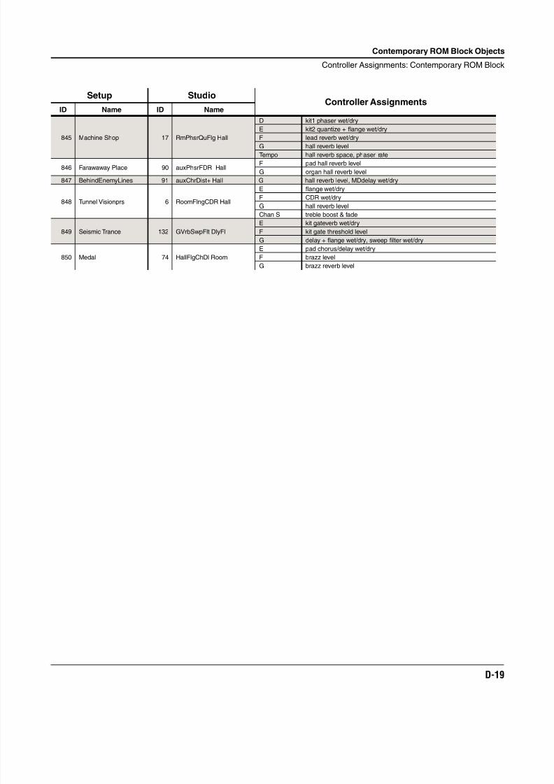
8/21/2019 MR_K2661
http://slidepdf.com/reader/full/mrk2661 441/499
Contemporary ROM Block Objects
Controller Assignments: Contemporary ROM Block
D-19
845 Machine Shop 17 RmPhsrQuFlg Hall
D kit1 phaser wet/dry
E kit2 quantize + flange wet/dry
F lead reverb wet/dryG hall reverb level
Tempo hall reverb space, phaser rate
846 Farawaway Place 90 auxPhsrFDR HallF pad hall reverb level
G organ hall reverb level
847 BehindEnemyLines 91 auxChrDist+ Hall G hall reverb level, MDdelay wet/dry
848 Tunnel Visionprs 6 RoomFlngCDR Hall
E flange wet/dry
F CDR wet/dry
G hall reverb level
Chan S treble boost & fade
849 Seismic Trance 132 GVrbSwpFlt DlyFl
E kit gateverb wet/dry
F kit gate threshold level
G delay + flange wet/dry, sweep filter wet/dry
850 Medal 74 HallFlgChDl Room
E pad chorus/delay wet/dry
F brazz level
G brazz reverb level
Setup StudioController Assignments
ID Name ID Name

8/21/2019 MR_K2661
http://slidepdf.com/reader/full/mrk2661 442/499
D-20
Contemporary ROM Block Objects
Controller Assignments: Contemporary ROM Block

8/21/2019 MR_K2661
http://slidepdf.com/reader/full/mrk2661 443/499
Orchestral ROM Block Objects
E-1
Appendix E
Orchestral ROM Block Objects
This Appendix describes the Orchestral ROM objects provided with your K2661.
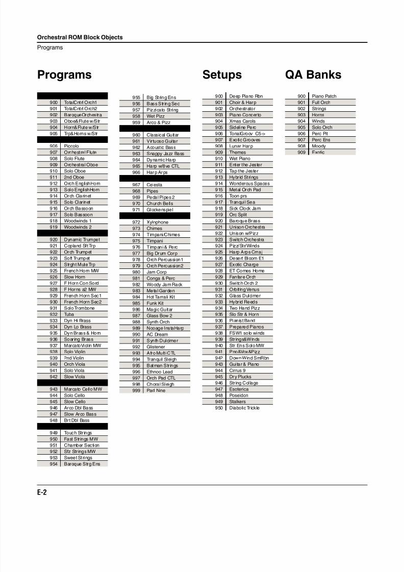
8/21/2019 MR_K2661
http://slidepdf.com/reader/full/mrk2661 444/499
E-2
Orchestral ROM Block Objects
Programs
Programs
Orchestras
900 TotalCntrl Orch1
901 TotalCntrl Orch2
902 BaroqueOrchestra
903 Oboe&Flute w/Str
904 Horn&Flute w/Str
905 Trp&Horns w/Str
Winds
906 Piccolo
907 Orchestral Flute
908 Solo Flute
909 Orchestral Oboe
910 Solo Oboe
911 2nd Oboe
912 Orch EnglishHorn
913 Solo EnglishHorn
914 Orch Clarinet
915 Solo Clarinet
916 Orch Bassoon
917 Solo Bassoon
918 Woodwinds 1
919 Woodwinds 2
Brass
920 Dynamic Trumpet
921 Copland Sft Trp
922 Orch Trumpet
923 Soft Trumpet
924 Strght Mute Trp
925 French Horn MW
926 Slow Horn
927 F Horn Con Sord
928 F Horns a2 MW
929 French Horn Sec1
930 French Horn Sec2
931 Solo Trombone
932 Tuba
933 Dyn Hi Brass
934 Dyn Lo Brass
935 Dyn Brass & Horn
936 Soaring Brass
937 MarcatoViolin MW
938 Solo Violin
939 2nd Violin
940 Orch Viola
941 Solo Viola
942 Slow Viola
Solo Strings
943 Marcato Cello MW
944 Solo Cello
945 Slow Cello946 Arco Dbl Bass
947 Slow Arco Bass
948 Brt Dbl Bass
String Sections
949 Touch Strings
950 Fast Strings MW
951 Chamber Section
952 Sfz Str ings MW
953 Sweet Strings
954 Baroque Strg Ens
955 Big String Ens
956 Bass String Sec
957 Pizzicato String
958 Wet Pizz
959 Arco & Pizz
Plucked Strings
960 Classical Guitar
961 Virtuoso Guitar
962 Acoust ic Bass
963 Snappy Jazz Bass
964 Dynamic Harp
965 Harp w/8ve CTL
966 Harp Arps
Keyboards
967 Celesta
968 Pipes
969 Pedal Pipes 2
970 Church Bells
971 Glockenspiel
Percussion
972 Xylophone
973 Chimes
974 Timpani/Chimes
975 Timpani
976 Timpani & Perc
977 Big Drum Corp
978 Orch Percussion1
979 Orch Percussion2
980 Jam Corp
981 Conga & Perc
982 Woody Jam Rack
983 Metal Garden
984 Hot Tamali Kit
985 Funk Kit
986 Magic Guitar
987 Glass Bow 2
988 Synth Orch
989 Nooage InstaHarp
990 AC Dream
991 Synth Dulcimer
992 Glistener
993 Afro Mult i CTL
994 Tranquil Sleigh
995 Batman Strings
996 Ethnoo Lead
997 Orch Pad CTL
998 Choral Sleigh
999 Pad Nine
Setups
900 Deep Piano Rbn
901 Choir & Harp
902 Orchestrator
903 Piano Concerto
904 Xmas Carols
905 Sideline Perc
906 TonalGroov C5->
907 Exotic Grooves
908 Lunar Harp
909 Themes
910 Wet Piano
911 Enter the Jester
912 Tap the Jester
913 Hybrid Strings
914 Wonderous Spaces
915 Metal Orch Pad
916 Toon prs
917 Tranqui l Sea
918 Sick Clock Jam
919 Orc Split
920 Baroque Brass
921 Unison Orchestra
922 Unison w/Pizz
923 Switch Orchestra
924 Pizz/Str/Winds
925 Harp Arps Cmaj
926 Desert Bloom E1
927 Exotic Charge
928 ET Comes Home
929 Fanfare Orch
930 Switch Orch 2
931 Orbit ing Venus
932 Glass Dulcimer
933 Hybrid Reeds
934 Two Hand Pizz
935 Slo Str & Horn
936 Pianist Band
937 Prepared Pianos
938 FSW1 solo winds
939 Strings&Winds
940 Str Ens Solo MW
941 Pno&Vox&Pizz
942 Down Wind SmRbn
943 Guitar & Piano
944 Cirrus 9
945 Dry Plucks
946 String Col lage
947 Esoterica
948 Poseidon
949 Stalkers950 Diabolic Trickle
QA Banks
900 Piano Patch
901 Full Orch
902 Strings
903 Horns
904 Winds
905 Solo Orch
906 Perc Pit
907 Perc Ens
908 Moody
909 Exotic
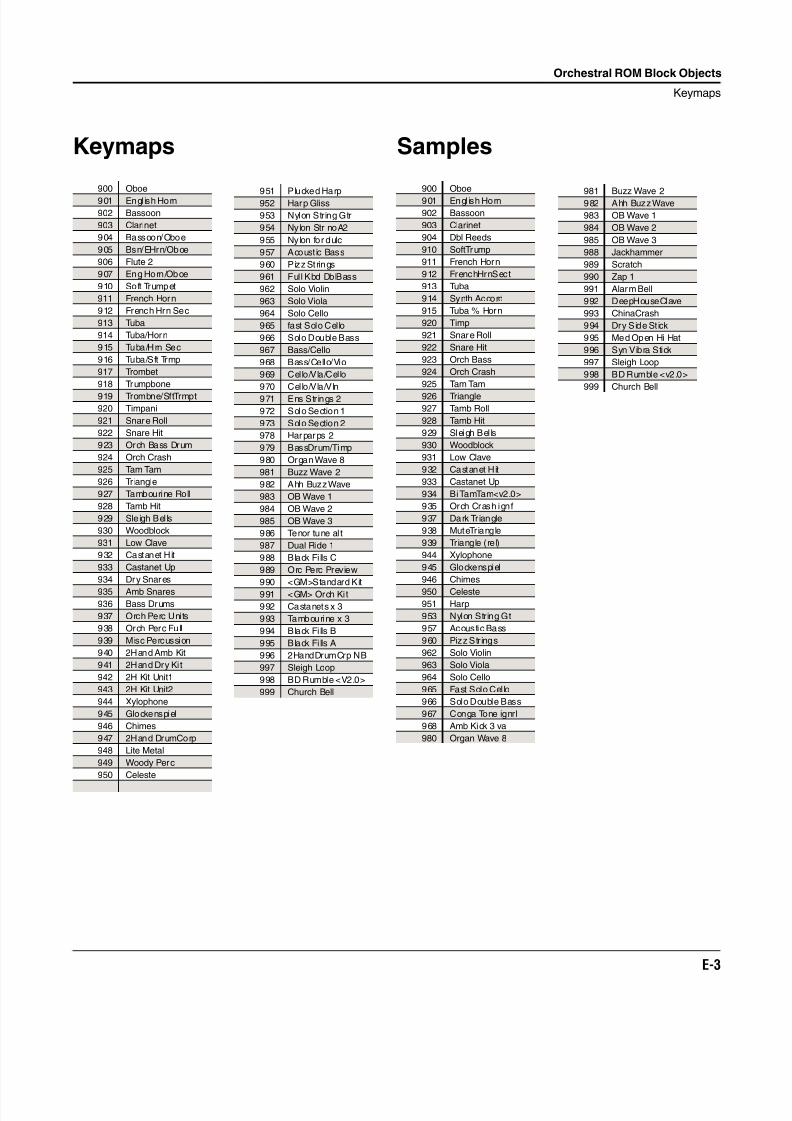
8/21/2019 MR_K2661
http://slidepdf.com/reader/full/mrk2661 445/499
Orchestral ROM Block Objects
Keymaps
E-3
Keymaps
900 Oboe
901 Engl ish Horn
902 Bassoon
903 Clarinet
904 Bassoon/Oboe
905 Bsn/EHrn/Oboe
906 Flute 2
907 Eng Horn/Oboe
910 Soft Trumpet
911 French Horn
912 French Hrn Sec
913 Tuba
914 Tuba/Horn
915 Tuba/Hrn Sec
916 Tuba/Sft Trmp
917 Trombet
918 Trumpbone
919 Trombne/SftTrmpt
920 Timpani
921 Snare Roll
922 Snare Hit
923 Orch Bass Drum
924 Orch Crash
925 Tam Tam
926 Tr iangle
927 Tambourine Roll
928 Tamb Hit
929 Sleigh Bel ls
930 Woodblock
931 Low Clave
932 Castanet Hit
933 Castanet Up
934 Dry Snares
935 Amb Snares
936 Bass Drums
937 Orch Perc Units
938 Orch Perc Full
939 Misc Percussion
940 2Hand Amb Kit
941 2Hand Dry Ki t
942 2H Kit Unit1
943 2H Kit Unit2
944 Xylophone
945 Glockenspiel
946 Chimes
947 2Hand DrumCorp
948 Lite Metal
949 Woody Perc
950 Celeste
951 Plucked Harp
952 Harp Gliss
953 Nylon String Gtr
954 Nylon Str noA2
955 Nylon for dulc
957 Acoust ic Bass
960 Pizz Strings
961 Full Kbd DblBass
962 Solo Violin
963 Solo Viola
964 Solo Cello
965 fast Solo Cello
966 Solo Double Bass
967 Bass/Cello
968 Bass/Cello/Vio
969 Cello/Vla/Cello
970 Cello/Vla/Vln
971 Ens Strings 2
972 Solo Section 1
973 Solo Section 2
978 Harparps 2
979 BassDrum/Timp
980 Organ Wave 8
981 Buzz Wave 2
982 Ahh Buzz Wave
983 OB Wave 1
984 OB Wave 2
985 OB Wave 3
986 Tenor tune al t
987 Dual Ride 1
988 Black Fi lls C
989 Orc Perc Preview
990 <GM>Standard Kit
991 <GM> Orch Ki t
992 Castanets x 3
993 Tambourine x 3
994 Black Fi lls B
995 Black Fi lls A
996 2HandDrumCrp NB
997 Sleigh Loop
998 BD Rumble <V2.0>
999 Church Bell
Samples
900 Oboe
901 Engl ish Horn
902 Bassoon
903 Clarinet
904 Dbl Reeds
910 SoftTrump
911 French Horn
912 FrenchHrnSect
913 Tuba
914 Synth Accord
915 Tuba % Horn
920 Timp
921 Snare Roll
922 Snare Hit
923 Orch Bass
924 Orch Crash
925 Tam Tam
926 Triangle
927 Tamb Roll
928 Tamb Hit
929 Sleigh Bel ls
930 Woodblock
931 Low Clave
932 Castanet Hit
933 Castanet Up
934 Bi TamTam<v2.0>
935 Orch Crash ignf
937 Dark Triangle
938 MuteTriangle
939 Triangle (rel)
944 Xylophone
945 Glockenspiel
946 Chimes
950 Celeste
951 Harp
953 Nylon String Gt
957 Acoustic Bass
960 Pizz Str ings
962 Solo Violin
963 Solo Viola
964 Solo Cello
965 Fast Solo Cello
966 Solo Double Bass
967 Conga Tone ignrl
968 Amb Kick 3 va
980 Organ Wave 8
981 Buzz Wave 2
982 Ahh Buzz Wave
983 OB Wave 1
984 OB Wave 2
985 OB Wave 3
988 Jackhammer
989 Scratch
990 Zap 1
991 Alarm Bell
992 DeepHouseClave
993 ChinaCrash
994 Dry Side St ick
995 Med Open Hi Hat
996 Syn Vibra Stick
997 Sleigh Loop
998 BD Rumble <v2.0>
999 Church Bell
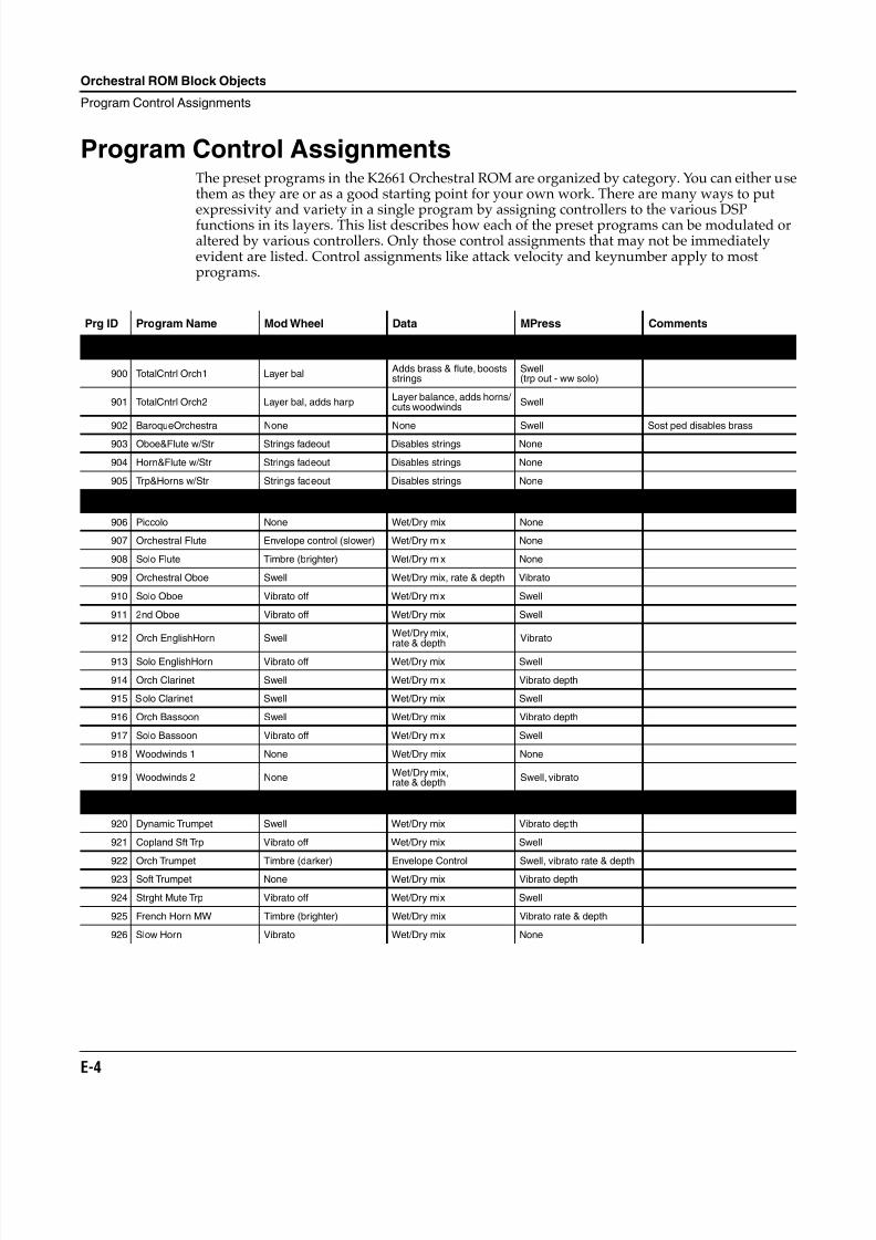
8/21/2019 MR_K2661
http://slidepdf.com/reader/full/mrk2661 446/499
E-4
Orchestral ROM Block Objects
Program Control Assignments
Program Control AssignmentsThe preset programs in the K2661 Orchestral ROM are organized by category. You can either usethem as they are or as a good starting point for your own work. There are many ways to put
expressivity and variety in a single program by assigning controllers to the various DSPfunctions in its layers. This list describes how each of the preset programs can be modulated oraltered by various controllers. Only those control assignments that may not be immediatelyevident are listed. Control assignments like attack velocity and keynumber apply to mostprograms.
Prg ID Program Name Mod Wheel Data MPress Comments
Orchestras
900 TotalCntrl Orch1 Layer balAdds brass & flute, boostsstrings
Swell(trp out - ww solo)
901 TotalCntrl Orch2 Layer bal, adds harpLayer balance, adds horns/ cuts woodwinds
Swell
902 BaroqueOrchestra None None Swell Sost ped disables brass
903 Oboe&Flute w/Str Strings fadeout Disables strings None
904 Horn&Flute w/Str Strings fadeout Disables strings None
905 Trp&Horns w/Str Strings fadeout Disables strings None
Winds
906 Piccolo None Wet/Dry mix None
907 Orchestral Flute Envelope control (slower) Wet/Dry mix None
908 Solo Flute Timbre (brighter) Wet/Dry mix None
909 Orchestral Oboe Swell Wet/Dry mix, rate & depth Vibrato
910 Solo Oboe Vibrato off Wet/Dry mix Swell
911 2nd Oboe Vibrato off Wet/Dry mix Swell
912 Orch EnglishHorn SwellWet/Dry mix,rate & depth
Vibrato
913 Solo EnglishHorn Vibrato off Wet/Dry mix Swell
914 Orch Clarinet Swell Wet/Dry mix Vibrato depth
915 Solo Clarinet Swell Wet/Dry mix Swell
916 Orch Bassoon Swell Wet/Dry mix Vibrato depth
917 Solo Bassoon Vibrato off Wet/Dry mix Swell
918 Woodwinds 1 None Wet/Dry mix None
919 Woodwinds 2 NoneWet/Dry mix,rate & depth
Swell, vibrato
Brass
920 Dynamic Trumpet Swell Wet/Dry mix Vibrato depth
921 Copland Sft Trp Vibrato off Wet/Dry mix Swell
922 Orch Trumpet Timbre (darker) Envelope Control Swell, vibrato rate & depth
923 Soft Trumpet None Wet/Dry mix Vibrato depth
924 Strght Mute Trp Vibrato off Wet/Dry mix Swell
925 French Horn MW Timbre (brighter) Wet/Dry mix Vibrato rate & depth
926 Slow Horn Vibrato Wet/Dry mix None
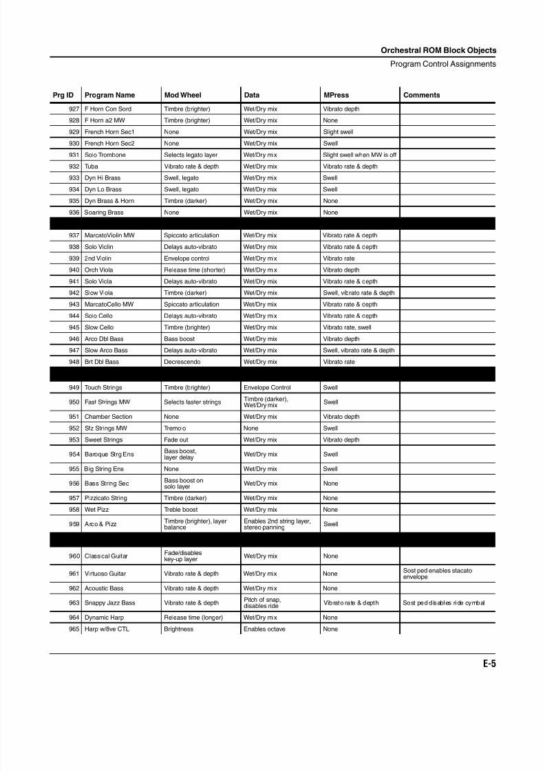
8/21/2019 MR_K2661
http://slidepdf.com/reader/full/mrk2661 447/499
Orchestral ROM Block Objects
Program Control Assignments
E-5
927 F Horn Con Sord Timbre (brighter) Wet/Dry mix Vibrato depth
928 F Horn a2 MW Timbre (brighter) Wet/Dry mix None
929 French Horn Sec1 None Wet/Dry mix Slight swell930 French Horn Sec2 None Wet/Dry mix Swell
931 Solo Trombone Selects legato layer Wet/Dry mix Slight swell when MW is off
932 Tuba Vibrato rate & depth Wet/Dry mix Vibrato rate & depth
933 Dyn Hi Brass Swell, legato Wet/Dry mix Swell
934 Dyn Lo Brass Swell, legato Wet/Dry mix Swell
935 Dyn Brass & Horn Timbre (darker) Wet/Dry mix None
936 Soaring Brass None Wet/Dry mix None
Solo Strings
937 MarcatoViolin MW Spiccato articulation Wet/Dry mix Vibrato rate & depth
938 Solo Violin Delays auto-vibrato Wet/Dry mix Vibrato rate & depth
939 2nd Violin Envelope control Wet/Dry mix Vibrato rate
940 Orch Viola Release time (shorter) Wet/Dry mix Vibrato depth
941 Solo Viola Delays auto-vibrato Wet/Dry mix Vibrato rate & depth
942 Slow Viola Timbre (darker) Wet/Dry mix Swell, vibrato rate & depth
943 MarcatoCello MW Spiccato articulation Wet/Dry mix Vibrato rate & depth
944 Solo Cello Delays auto-vibrato Wet/Dry mix Vibrato rate & depth
945 Slow Cello Timbre (brighter) Wet/Dry mix Vibrato rate, swell
946 Arco Dbl Bass Bass boost Wet/Dry mix Vibrato depth
947 Slow Arco Bass Delays auto-vibrato Wet/Dry mix Swell, vibrato rate & depth
948 Brt Dbl Bass Decrescendo Wet/Dry mix Vibrato rate
Section Strings
949 Touch Strings Timbre (brighter) Envelope Control Swell
950 Fast Strings MW Selects faster strings
Timbre (darker),
Wet/Dry mix Swell
951 Chamber Section None Wet/Dry mix Vibrato depth
952 Sfz Strings MW Tremolo None Swell
953 Sweet Strings Fade out Wet/Dry mix Vibrato depth
954 Baroque Strg EnsBass boost,layer delay
Wet/Dry mix Swell
955 Big String Ens None Wet/Dry mix Swell
956 Bass String SecBass boost onsolo layer
Wet/Dry mix None
957 Pizzicato String Timbre (darker) Wet/Dry mix None
958 Wet Pizz Treble boost Wet/Dry mix None
959 Arco & PizzTimbre (brighter), layerbalance
Enables 2nd string layer,stereo panning
Swell
Plucked Strings
960 Classical GuitarFade/disableskey-up layer
Wet/Dry mix None
961 Virtuoso Guitar Vibrato rate & depth Wet/Dry mix NoneSost ped enables stacatoenvelope
962 Acoustic Bass Vibrato rate & depth Wet/Dry mix None
963 Snappy Jazz Bass Vibrato rate & depthPitch of snap,disables ride
Vibrato rate & depth Sost ped disables ride cymbal
964 Dynamic Harp Release time (longer) Wet/Dry mix None
965 Harp w/8ve CTL Brightness Enables octave None
Prg ID Program Name Mod Wheel Data MPress Comments
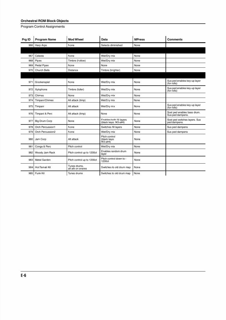
8/21/2019 MR_K2661
http://slidepdf.com/reader/full/mrk2661 448/499
E-6
Orchestral ROM Block Objects
Program Control Assignments
966 Harp Arps None Selects diminished None
Keyboards
967 Celesta None Wet/Dry mix None
968 Pipes Timbre (hollow) Wet/Dry mix None
969 Pedal Pipes None None None
970 Church Bells Distance Timbre (brighter) None
Percussion
971 Glockenspiel None Wet/Dry mix NoneSus ped enables key-up layer(for rolls)
972 Xylophone Timbre (fuller) Wet/Dry mix NoneSus ped enables key-up layer(for rolls)
973 Chimes None Wet/Dry mix None
974 Timpani/Chimes Alt attack (timp) Wet/Dry mix None
975 Timpani Alt attack Wet/Dry mix NoneSus ped enables key-up layer(for rolls)
976 Timpani & Perc Alt attack (timp) None None Sost ped enables bass drum.Sus ped dampens.
977 Big Drum Corp NoneEnables both fill layers(black keys: f#3-a#4)
NoneSost ped switches layers. Susped dampens.
978 Orch Percussion1 None Switches fill layers None Sus ped dampens
979 Orch Percussion2 None Wet/Dry mix None Sus ped dampens
980 Jam Corp Alt attackPitch control(black keys:f#3-a#4)
None
981 Conga & Perc Pitch control Wet/Dry mix None
982 Woody Jam Rack Pitch control up to 1200ctEnables random drumlayer
None
983 Metal Garden Pitch control up to 1200ctPitch control down to -1200ct
None
984 Hot Tamali Kit
Tunes drums,
alt atk on snares Switches to old drum map None
985 Funk Kit Tunes drums Switches to old drum map None
Prg ID Program Name Mod Wheel Data MPress Comments
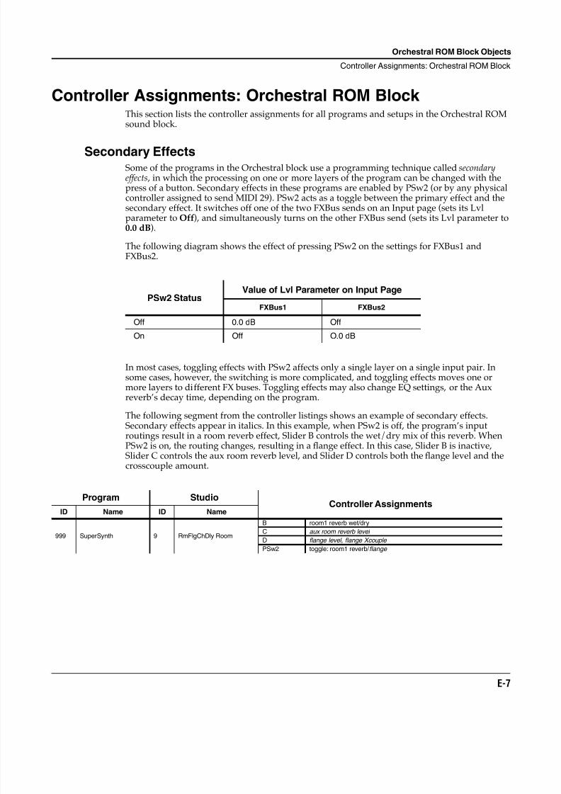
8/21/2019 MR_K2661
http://slidepdf.com/reader/full/mrk2661 449/499
Orchestral ROM Block Objects
Controller Assignments: Orchestral ROM Block
E-7
Controller Assignments: Orchestral ROM Block This section lists the controller assignments for all programs and setups in the Orchestral ROMsound block.
Secondary EffectsSome of the programs in the Orchestral block use a programming technique called secondaryeffects , in which the processing on one or more layers of the program can be changed with thepress of a button. Secondary effects in these programs are enabled by PSw2 (or by any physicalcontroller assigned to send MIDI 29). PSw2 acts as a toggle between the primary effect and thesecondary effect. It switches off one of the two FXBus sends on an Input page (sets its Lvlparameter to Off), and simultaneously turns on the other FXBus send (sets its Lvl parameter to0.0 dB).
The following diagram shows the effect of pressing PSw2 on the settings for FXBus1 andFXBus2.
In most cases, toggling effects with PSw2 affects only a single layer on a single input pair. Insome cases, however, the switching is more complicated, and toggling effects moves one ormore layers to different FX buses. Toggling effects may also change EQ settings, or the Auxreverb’s decay time, depending on the program.
The following segment from the controller listings shows an example of secondary effects.Secondary effects appear in italics. In this example, when PSw2 is off, the program’s inputroutings result in a room reverb effect, Slider B controls the wet/dry mix of this reverb. WhenPSw2 is on, the routing changes, resulting in a flange effect. In this case, Slider B is inactive,Slider C controls the aux room reverb level, and Slider D controls both the flange level and thecrosscouple amount.
PSw2 StatusValue of Lvl Parameter on Input Page
FXBus1 FXBus2
Off 0.0 dB Off
On Off O.0 dB
Program StudioController Assignments
ID Name ID Name
999 SuperSynth 9 RmFlgChDly Room
B room1 reverb wet/dry
C aux room reverb level
D flange level, flange Xcouple
PSw2 toggle: room1 reverb/ flange
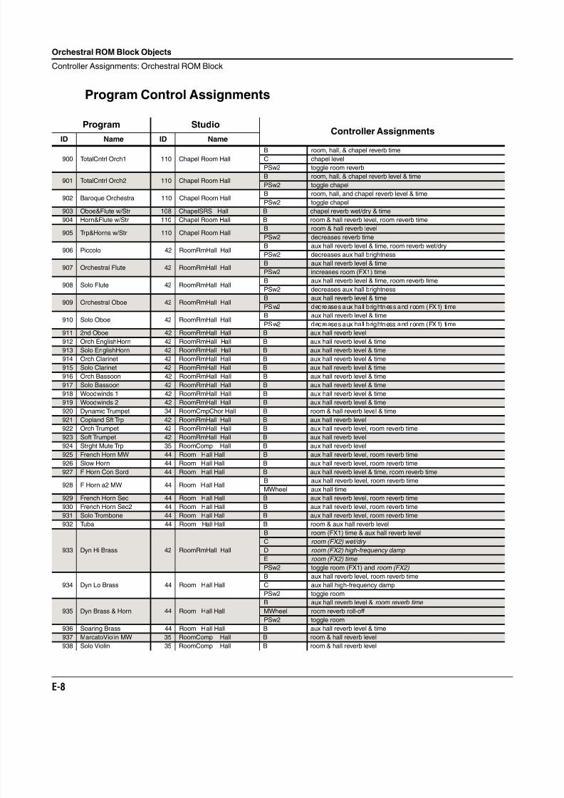
8/21/2019 MR_K2661
http://slidepdf.com/reader/full/mrk2661 450/499
E-8
Orchestral ROM Block Objects
Controller Assignments: Orchestral ROM Block
Program Control Assignments
Program StudioController Assignments
ID Name ID Name
900 TotalCntrl Orch1 110 Chapel Room Hall
B room, hall, & chapel reverb time
C chapel level
PSw2 toggle room reverb
901 TotalCntrl Orch2 110 Chapel Room HallB room, hall, & chapel reverb level & time
PSw2 toggle chapel
902 Baroque Orchestra 110 Chapel Room HallB room, hall, and chapel reverb level & time
PSw2 toggle chapel
903 Oboe&Flute w/Str 108 ChapelSRS Hall B chapel reverb wet/dry & time
904 Horn&Flute w/Str 110 Chapel Room Hall B room & hall reverb level, room reverb time
905 Trp&Horns w/Str 110 Chapel Room HallB room & hall reverb level
PSw2 decreases reverb time
906 Piccolo 42 RoomRmHall HallB aux hall reverb level & time, room reverb wet/dry
PSw2 decreases aux hall brightness
907 Orchestral Flute 42 RoomRmHall HallB aux hall reverb level & time
PSw2 increases room (FX1) time
908 Solo Flute 42 RoomRmHall Hall B aux hall reverb level & time, room reverb timePSw2 decreases aux hall brightness
909 Orchestral Oboe 42 RoomRmHall HallB aux hall reverb level & time
PSw2 decreases aux hall brightness and room (FX1) time
910 Solo Oboe 42 RoomRmHall HallB aux hall reverb level & time
PSw2 decreases aux hall brightness and room (FX1) time
911 2nd Oboe 42 RoomRmHall Hall B aux hall reverb level
912 Orch EnglishHorn 42 RoomRmHall Hall B aux hall reverb level & time
913 Solo EnglishHorn 42 RoomRmHall Hall B aux hall reverb level & time
914 Orch Clarinet 42 RoomRmHall Hall B aux hall reverb level & time
915 Solo Clarinet 42 RoomRmHall Hall B aux hall reverb level & time
916 Orch Bassoon 42 RoomRmHall Hall B aux hall reverb level & time
917 Solo Bassoon 42 RoomRmHall Hall B aux hall reverb level & time
918 Woodwinds 1 42 RoomRmHall Hall B aux hall reverb level & time
919 Woodwinds 2 42 RoomRmHall Hall B aux hall reverb level & time
920 Dynamic Trumpet 34 RoomCmpChor Hall B room & hall reverb level & time
921 Copland Sft Trp 42 RoomRmHall Hall B aux hall reverb level922 Orch Trumpet 42 RoomRmHall Hall B aux hall reverb level, room reverb time
923 Soft Trumpet 42 RoomRmHall Hall B aux hall reverb level
924 Strght Mute Trp 35 RoomComp Hall B aux hall reverb level
925 French Horn MW 44 Room Hall Hall B aux hall reverb level, room reverb time
926 Slow Horn 44 Room Hall Hall B aux hall reverb level, room reverb time
927 F Horn Con Sord 44 Room Hall Hall B aux hall reverb level & time, room reverb time
928 F Horn a2 MW 44 Room Hall HallB aux hall reverb level, room reverb time
MWheel aux hall time
929 French Horn Sec 44 Room Hall Hall B aux hall reverb level, room reverb time
930 French Horn Sec2 44 Room Hall Hall B aux hall reverb level, room reverb time
931 Solo Trombone 44 Room Hall Hall B aux hall reverb level, room reverb time
932 Tuba 44 Room Hall Hall B room & aux hall reverb level
933 Dyn Hi Brass 42 RoomRmHall Hall
B room (FX1) time & aux hall reverb level
C room (FX2) wet/dry
D room (FX2) high-frequency damp
E room (FX2) time PSw2 toggle room (FX1) and room (FX2)
934 Dyn Lo Brass 44 Room Hall Hall
B aux hall reverb level, room reverb time
C aux hall high-frequency damp
PSw2 toggle room
935 Dyn Brass & Horn 44 Room Hall Hall
B aux hall reverb level & room reverb time
MWheel room reverb roll-off
PSw2 toggle room
936 Soaring Brass 44 Room Hall Hall B aux hall reverb level & time
937 MarcatoViolin MW 35 RoomComp Hall B room & hall reverb level
938 Solo Violin 35 RoomComp Hall B room & hall reverb level
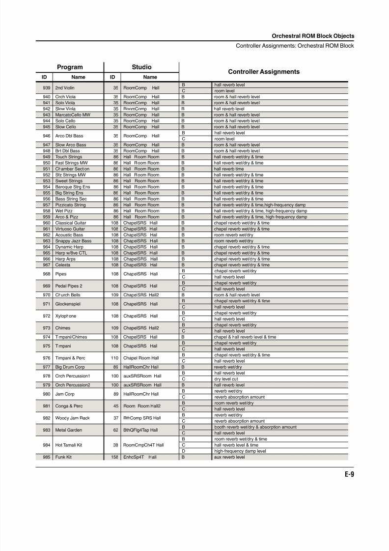
8/21/2019 MR_K2661
http://slidepdf.com/reader/full/mrk2661 451/499
Orchestral ROM Block Objects
Controller Assignments: Orchestral ROM Block
E-9
939 2nd Violin 35 RoomComp HallB hall reverb level
C room level
940 Orch Viola 35 RoomComp Hall B room & hall reverb level941 Solo Viola 35 RoomComp Hall B room & hall reverb level
942 Slow Viola 35 RoomComp Hall B hall reverb level
943 MarcatoCello MW 35 RoomComp Hall B room & hall reverb level
944 Solo Cello 35 RoomComp Hall B room & hall reverb level
945 Slow Cello 35 RoomComp Hall B room & hall reverb level
946 Arco Dbl Bass 35 RoomComp HallB hall reverb level
C room level
947 Slow Arco Bass 35 RoomComp Hall B room & hall reverb level
948 Brt Dbl Bass 35 RoomComp Hall B room & hall reverb level
949 Touch Strings 86 Hall Room Room B hall reverb wet/dry & time
950 Fast Strings MW 86 Hall Room Room B hall reverb wet/dry & time
951 Chamber Section 86 Hall Room Room B hall reverb time
952 Sfz Strings MW 86 Hall Room Room B hall reverb wet/dry & time
953 Sweet Strings 86 Hall Room Room B hall reverb wet/dry & time
954 Baroque Strg Ens 86 Hall Room Room B hall reverb wet/dry & time
955 Big String Ens 86 Hall Room Room B hall reverb wet/dry & time956 Bass String Sec 86 Hall Room Room B hall reverb wet/dry & time
957 Pizzicato String 86 Hall Room Room B hall reverb wet/dry & time,high-frequency damp
958 Wet Pizz 86 Hall Room Room B hall reverb wet/dry & time, high-frequency damp
959 Arco & Pizz 86 Hall Room Room B hall reverb wet/dry & time, high-frequency damp
960 Classical Guitar 108 ChapelSRS Hall B chapel reverb wet/dry & time
961 Virtuoso Guitar 108 ChapelSRS Hall B chapel reverb wet/dry & time
962 Acoustic Bass 108 ChapelSRS Hall B room reverb wet/dry
963 Snappy Jazz Bass 108 ChapelSRS Hall B room reverb wet/dry
964 Dynamic Harp 108 ChapelSRS Hall B chapel reverb wet/dry & time
965 Harp w/8ve CTL 108 ChapelSRS Hall B chapel reverb wet/dry & time
966 Harp Arps 108 ChapelSRS Hall B chapel reverb wet/dry & time
967 Celesta 108 ChapelSRS Hall B chapel reverb wet/dry & time
968 Pipes 108 ChapelSRS HallB chapel reverb wet/dry
C hall reverb level
969 Pedal Pipes 2 108 ChapelSRS HallB chapel reverb wet/dry
C hall reverb level970 Church Bells 109 ChapelSRS Hall2 B room & hall reverb level
971 Glockenspiel 108 ChapelSRS HallB chapel reverb wet/dry & time
C hall reverb level
972 Xylophone 108 ChapelSRS HallB chapel reverb wet/dry
C hall reverb level
973 Chimes 109 ChapelSRS Hall2B chapel reverb wet/dry
C hall reverb level
974 Timpani/Chimes 108 ChapelSRS Hall B chapel & hall reverb level & time
975 Timpani 108 ChapelSRS HallB chapel reverb wet/dry
C hall reverb level
976 Timpani & Perc 110 Chapel Room HallB chapel reverb wet/dry & time
C hall reverb level
977 Big Drum Corp 89 HallRoomChr Hall B reverb wet/dry
978 Orch Percussion1 100 auxSRSRoom HallB hall reverb level
C dry level cut
979 Orch Percussion2 100 auxSRSRoom Hall B hall reverb level
980 Jam Corp 89 HallRoomChr HallB reverb wet/dry
C reverb absorption amount
981 Conga & Perc 45 Room Room Hall2B room reverb wet/dry
C hall reverb level
982 Woody Jam Rack 37 BthComp SRS HallB reverb wet/dry
C reverb absorption amount
983 Metal Garden 62 BthQFlg4Tap HallB booth reverb wet/dry & absorption amount
C hall reverb level
984 Hot Tamali Kit 38 RoomCmpCh4T Hall
B room reverb wet/dry & time
C hall reverb level & time
D high-frequency damp level
985 Funk Kit 158 EnhcSp4T Hall B aux reverb level
Program StudioController Assignments
ID Name ID Name
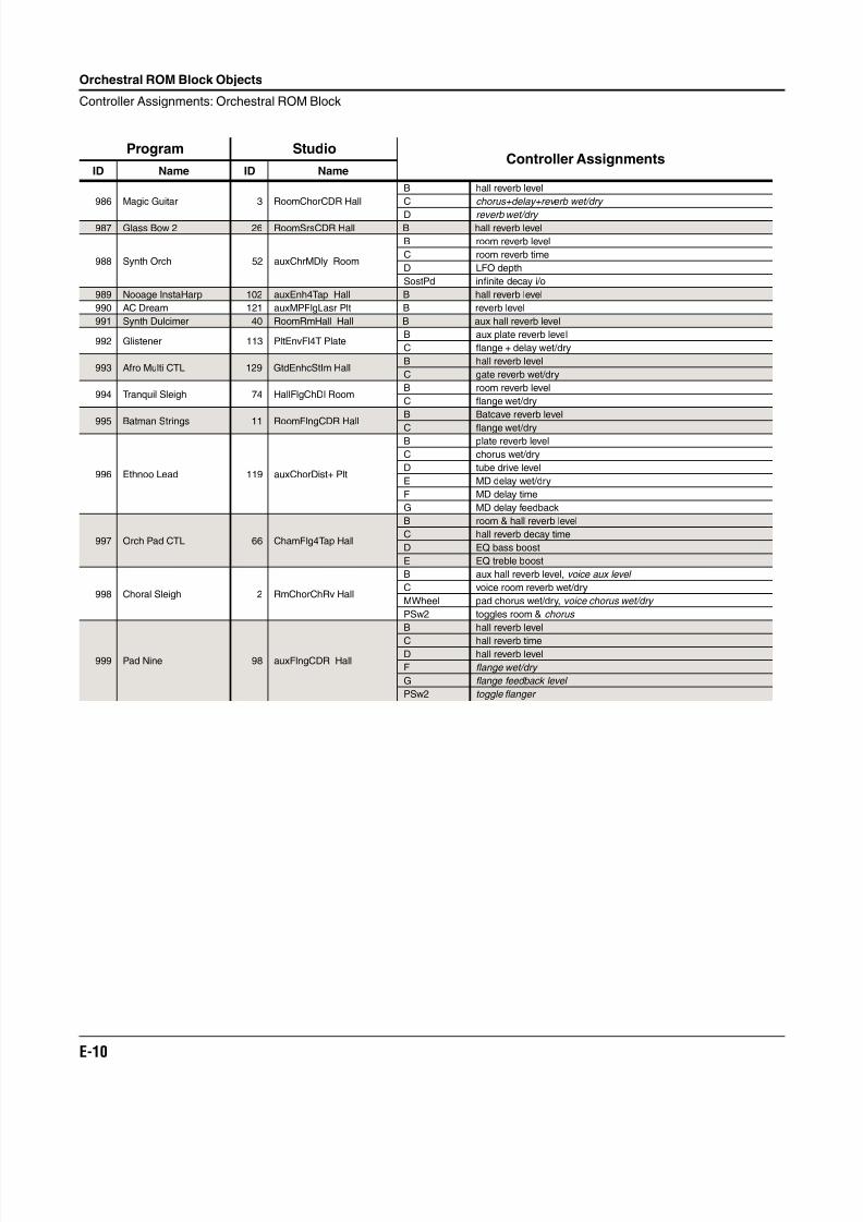
8/21/2019 MR_K2661
http://slidepdf.com/reader/full/mrk2661 452/499
E-10
Orchestral ROM Block Objects
Controller Assignments: Orchestral ROM Block
986 Magic Guitar 3 RoomChorCDR Hall
B hall reverb level
C chorus+delay+reverb wet/dry
D reverb wet/dry 987 Glass Bow 2 26 RoomSrsCDR Hall B hall reverb level
988 Synth Orch 52 auxChrMDly Room
B room reverb level
C room reverb time
D LFO depth
SostPd infinite decay i/o
989 Nooage InstaHarp 102 auxEnh4Tap Hall B hall reverb level
990 AC Dream 121 auxMPFlgLasr Plt B reverb level
991 Synth Dulcimer 40 RoomRmHall Hall B aux hall reverb level
992 Glistener 113 PltEnvFl4T PlateB aux plate reverb level
C flange + delay wet/dry
993 Afro Multi CTL 129 GtdEnhcStIm HallB hall reverb level
C gate reverb wet/dry
994 Tranquil Sleigh 74 HallFlgChDl RoomB room reverb level
C flange wet/dry
995 Batman Strings 11 RoomFlngCDR HallB Batcave reverb level
C flange wet/dry
996 Ethnoo Lead 119 auxChorDist+ Plt
B plate reverb level
C chorus wet/dry
D tube drive level
E MD delay wet/dry
F MD delay time
G MD delay feedback
997 Orch Pad CTL 66 ChamFlg4Tap Hall
B room & hall reverb level
C hall reverb decay time
D EQ bass boost
E EQ treble boost
998 Choral Sleigh 2 RmChorChRv Hall
B aux hall reverb level, voice aux level
C voice room reverb wet/dry
MWheel pad chorus wet/dry, voice chorus wet/dry
PSw2 toggles room & chorus
999 Pad Nine 98 auxFlngCDR Hall
B hall reverb level
C hall reverb timeD hall reverb level
F flange wet/dry
G flange feedback level
PSw2 toggle flanger
Program StudioController Assignments
ID Name ID Name
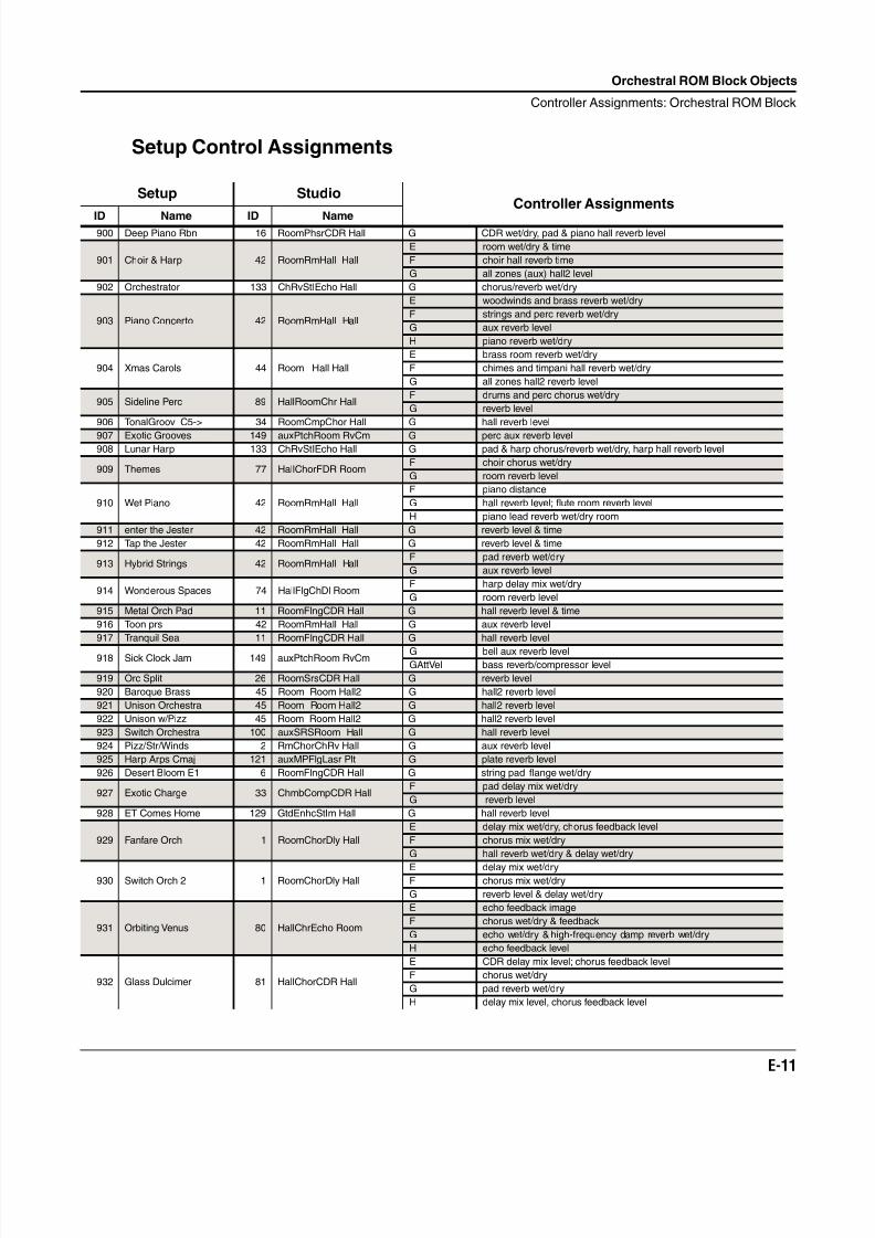
8/21/2019 MR_K2661
http://slidepdf.com/reader/full/mrk2661 453/499
Orchestral ROM Block Objects
Controller Assignments: Orchestral ROM Block
E-11
Setup Control Assignments
Setup StudioController Assignments
ID Name ID Name900 Deep Piano Rbn 16 RoomPhsrCDR Hall G CDR wet/dry, pad & piano hall reverb level
901 Choir & Harp 42 RoomRmHall Hall
E room wet/dry & time
F choir hall reverb time
G all zones (aux) hall2 level
902 Orchestrator 133 ChRvStIEcho Hall G chorus/reverb wet/dry
903 Piano Concerto 42 RoomRmHall Hall
E woodwinds and brass reverb wet/dry
F strings and perc reverb wet/dry
G aux reverb level
H piano reverb wet/dry
904 Xmas Carols 44 Room Hall Hall
E brass room reverb wet/dry
F chimes and timpani hall reverb wet/dry
G all zones hall2 reverb level
905 Sideline Perc 89 HallRoomChr HallF drums and perc chorus wet/dry
G reverb level
906 TonalGroov C5-> 34 RoomCmpChor Hall G hall reverb level
907 Exotic Grooves 149 auxPtchRoom RvCm G perc aux reverb level908 Lunar Harp 133 ChRvStIEcho Hall G pad & harp chorus/reverb wet/dry, harp hall reverb level
909 Themes 77 HallChorFDR RoomF choir chorus wet/dry
G room reverb level
910 Wet Piano 42 RoomRmHall Hall
F piano distance
G hall reverb level; flute room reverb level
H piano lead reverb wet/dry room
911 enter the Jester 42 RoomRmHall Hall G reverb level & time
912 Tap the Jester 42 RoomRmHall Hall G reverb level & time
913 Hybrid Strings 42 RoomRmHall HallF pad reverb wet/dry
G aux reverb level
914 Wonderous Spaces 74 HallFlgChDl RoomF harp delay mix wet/dry
G room reverb level
915 Metal Orch Pad 11 RoomFlngCDR Hall G hall reverb level & time
916 Toon prs 42 RoomRmHall Hall G aux reverb level
917 Tranquil Sea 11 RoomFlngCDR Hall G hall reverb level
918 Sick Clock Jam 149 auxPtchRoom RvCm G bell aux reverb levelGAttVel bass reverb/compressor level
919 Orc Split 26 RoomSrsCDR Hall G reverb level
920 Baroque Brass 45 Room Room Hall2 G hall2 reverb level
921 Unison Orchestra 45 Room Room Hall2 G hall2 reverb level
922 Unison w/Pizz 45 Room Room Hall2 G hall2 reverb level
923 Switch Orchestra 100 auxSRSRoom Hall G hall reverb level
924 Pizz/Str/Winds 2 RmChorChRv Hall G aux reverb level
925 Harp Arps Cmaj 121 auxMPFlgLasr Plt G plate reverb level
926 Desert Bloom E1 6 RoomFlngCDR Hall G string pad flange wet/dry
927 Exotic Charge 33 ChmbCompCDR HallF pad delay mix wet/dry
G reverb level
928 ET Comes Home 129 GtdEnhcStIm Hall G hall reverb level
929 Fanfare Orch 1 RoomChorDly Hall
E delay mix wet/dry, chorus feedback level
F chorus mix wet/dry
G hall reverb wet/dry & delay wet/dry
930 Switch Orch 2 1 RoomChorDly HallE delay mix wet/dryF chorus mix wet/dry
G reverb level & delay wet/dry
931 Orbiting Venus 80 HallChrEcho Room
E echo feedback image
F chorus wet/dry & feedback
G echo wet/dry & high-frequency damp reverb wet/dry
H echo feedback level
932 Glass Dulcimer 81 HallChorCDR Hall
E CDR delay mix level; chorus feedback level
F chorus wet/dry
G pad reverb wet/dry
H delay mix level, chorus feedback level
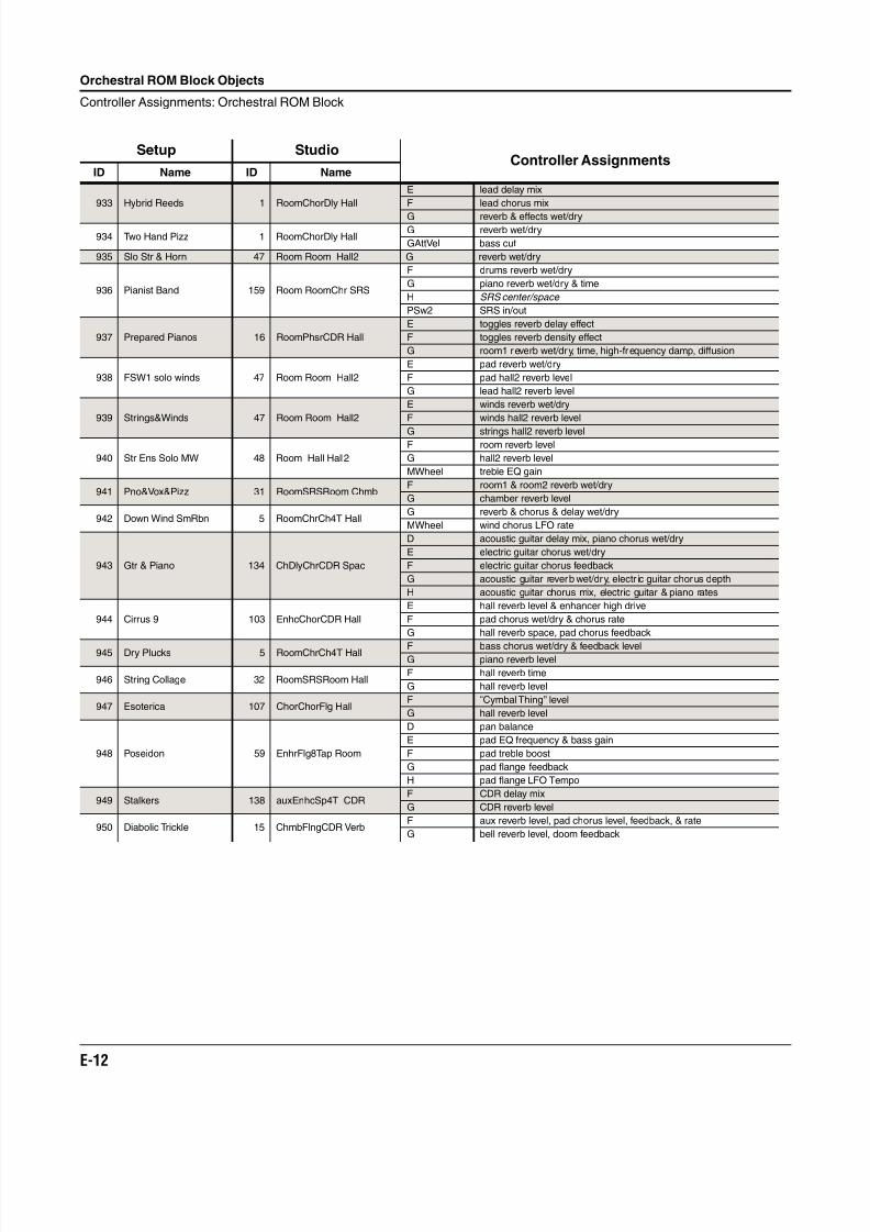
8/21/2019 MR_K2661
http://slidepdf.com/reader/full/mrk2661 454/499
E-12
Orchestral ROM Block Objects
Controller Assignments: Orchestral ROM Block
933 Hybrid Reeds 1 RoomChorDly Hall
E lead delay mix
F lead chorus mix
G reverb & effects wet/dry
934 Two Hand Pizz 1 RoomChorDly HallG reverb wet/dry
GAttVel bass cut
935 Slo Str & Horn 47 Room Room Hall2 G reverb wet/dry
936 Pianist Band 159 Room RoomChr SRS
F drums reverb wet/dry
G piano reverb wet/dry & time
H SRS center/space
PSw2 SRS in/out
937 Prepared Pianos 16 RoomPhsrCDR Hall
E toggles reverb delay effect
F toggles reverb density effect
G room1 reverb wet/dry, time, high-frequency damp, diffusion
938 FSW1 solo winds 47 Room Room Hall2
E pad reverb wet/dry
F pad hall2 reverb level
G lead hall2 reverb level
939 Strings&Winds 47 Room Room Hall2
E winds reverb wet/dry
F winds hall2 reverb level
G strings hall2 reverb level
940 Str Ens Solo MW 48 Room Hall Hall2
F room reverb level
G hall2 reverb level
MWheel treble EQ gain
941 Pno&Vox&Pizz 31 RoomSRSRoom ChmbF room1 & room2 reverb wet/dry
G chamber reverb level
942 Down Wind SmRbn 5 RoomChrCh4T HallG reverb & chorus & delay wet/dry
MWheel wind chorus LFO rate
943 Gtr & Piano 134 ChDlyChrCDR Spac
D acoustic guitar delay mix, piano chorus wet/dry
E electric guitar chorus wet/dry
F electric guitar chorus feedback
G acoustic guitar reverb wet/dry, electr ic guitar chorus depth
H acoustic guitar chorus mix, electric guitar & piano rates
944 Cirrus 9 103 EnhcChorCDR Hall
E hall reverb level & enhancer high drive
F pad chorus wet/dry & chorus rate
G hall reverb space, pad chorus feedback
945 Dry Plucks 5 RoomChrCh4T Hall F bass chorus wet/dry & feedback levelG piano reverb level
946 String Collage 32 RoomSRSRoom HallF hall reverb time
G hall reverb level
947 Esoterica 107 ChorChorFlg HallF “Cymbal Thing” level
G hall reverb level
948 Poseidon 59 EnhrFlg8Tap Room
D pan balance
E pad EQ frequency & bass gain
F pad treble boost
G pad flange feedback
H pad flange LFO Tempo
949 Stalkers 138 auxEnhcSp4T CDRF CDR delay mix
G CDR reverb level
950 Diabolic Trickle 15 ChmbFlngCDR VerbF aux reverb level, pad chorus level, feedback, & rate
G bell reverb level, doom feedback
Setup StudioController Assignments
ID Name ID Name
8/21/2019 MR_K2661
http://slidepdf.com/reader/full/mrk2661 455/499
Appendix F
SD Piano ROM Option
SmartMedia ContentsThe objects for ROM3 (SD Piano) are included on the SmartMedia card that comes with yourK2661. The procedure for installing the objects is described in the installation instructions thatcame with your SD Piano option kit.
Sympathetic VibrationsWhen you play a chord on an acoustic piano and hold down the keys while the notes decay, the
dampers on the corresponding strings remain up, and you hear a particular set of harmonicsthat evolve from the undamped strings. You don’t hear any significant harmonics from the otherstrings.
If you play the same chord and hold it with the sustain pedal, you’ll hear a much different,richer set of harmonics as the notes decay. That’s because all the strings are undamped, and eachstring gradually begins to vibrate at its resonant frequency, in response to the vibrations of thestrings struck by the hammers.
This phenomenon is called sympathetic vibration, and is an important component of the soundof an acoustic piano. The most noticeable of these sympathetic vibrations come from the stringswhose fundamental pitches match the harmonics of the strings that were struck by thehammers.
To create a more realistic acoustic piano sound for the SD Piano option, Kurzweil sound
engineers have developed special effects settings that imitate sympathetic vibrations. Whenyou’re playing one of the SD Piano programs with ID 700–713, and you’re not using the sustainpedal, the K2661’s audio signal passes through FXBus 1, then to the AuxBus, which applies atypical room or hall reverb.
When you use the sustain pedal, the signal passes FXBus 1 and FXBus 2 before going to theAuxBus. FXBus 2 applies a chain of reverbs programmed to resemble an acoustic piano’ssympathetic vibrations.
You can use the Data slider (or any physical controller sending MIDI 6) to adjust the level thesympathetic vibration effect.
Modifying SD Piano Programs
If you want to change the room ambiance on an SD Piano program without losing thesympathetic vibration effect, use the Studio Editor to assign a different effect on the AuxBus ofthe studio used by that program. If you want to remove the sympathetic vibrations, remove theeffect from FXBus 2.
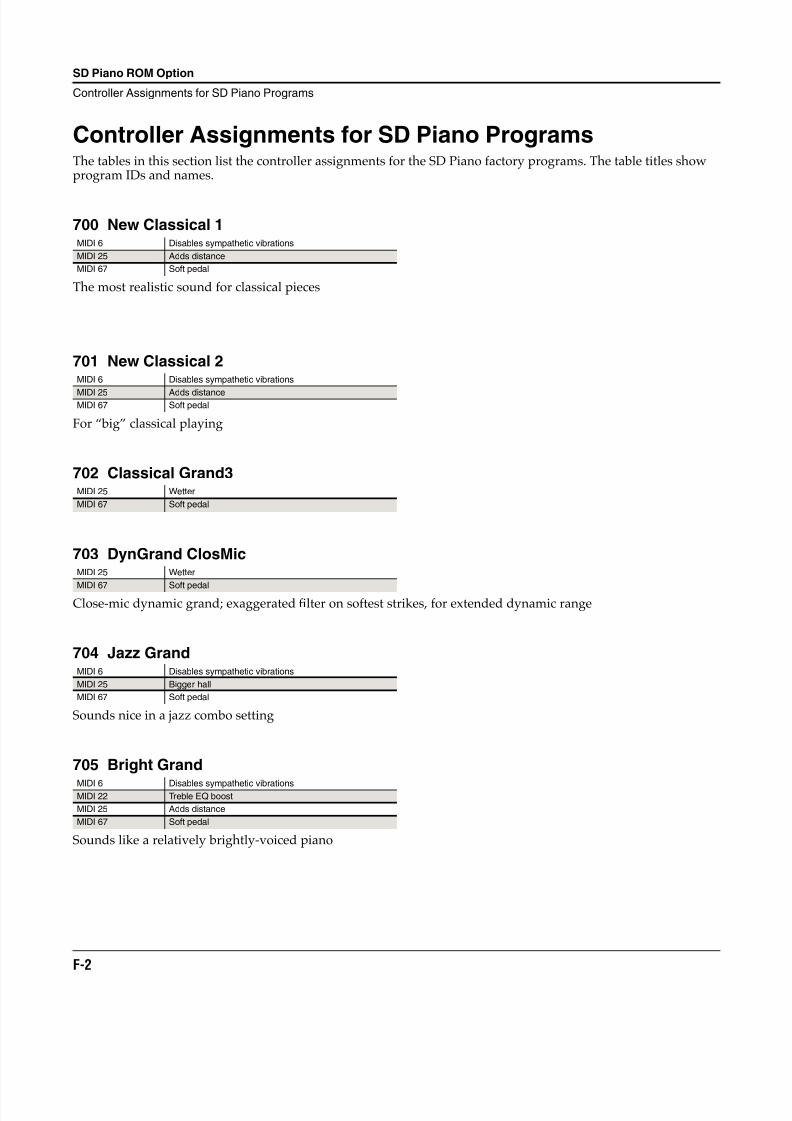
8/21/2019 MR_K2661
http://slidepdf.com/reader/full/mrk2661 456/499
F-2
SD Piano ROM Option
Controller Assignments for SD Piano Programs
Controller Assignments for SD Piano ProgramsThe tables in this section list the controller assignments for the SD Piano factory programs. The table titles showprogram IDs and names.
700 New Classical 1
The most realistic sound for classical pieces
701 New Classical 2
For “big” classical playing
702 Classical Grand3
703 DynGrand ClosMic
Close-mic dynamic grand; exaggerated filter on softest strikes, for extended dynamic range
704 Jazz Grand
Sounds nice in a jazz combo setting
705 Bright Grand
Sounds like a relatively brightly-voiced piano
MIDI 6 Disables sympathetic vibrations
MIDI 25 Adds distance
MIDI 67 Soft pedal
MIDI 6 Disables sympathetic vibrations
MIDI 25 Adds distanceMIDI 67 Soft pedal
MIDI 25 Wetter
MIDI 67 Soft pedal
MIDI 25 Wetter
MIDI 67 Soft pedal
MIDI 6 Disables sympathetic vibrations
MIDI 25 Bigger hall
MIDI 67 Soft pedal
MIDI 6 Disables sympathetic vibrationsMIDI 22 Treble EQ boost
MIDI 25 Adds distance
MIDI 67 Soft pedal
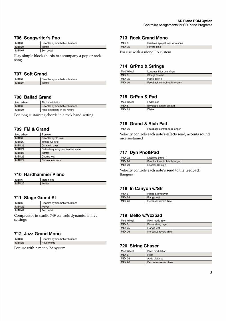
8/21/2019 MR_K2661
http://slidepdf.com/reader/full/mrk2661 457/499
SD Piano ROM Option
Controller Assignments for SD Piano Programs
3
706 Songwriter’s Pno
Play simple block chords to accompany a pop or rocksong
707 Soft Grand
708 Ballad Grand
For long sustaining chords in a rock band setting
709 FM & Grand
710 Hardhammer Piano
711 Stage Grand St
Compressor in studio 749 controls dynamics in livesettings
712 Jazz Grand Mono
For use with a mono PA system
MIDI 6 Disables sympathetic vibrations
MIDI 25 Wetter
MIDI 67 Soft pedal
MIDI 6 Disables sympathetic vibrations
MIDI 25 Wetter
Mod Wheel Pitch modulation
MIDI 6 Disables sympathetic vibrations
MIDI 25 Adds chorusing in the reverb
Mod Wheel Tremolo
MIDI 6 Disables synth layer
MIDI 22 Timbre Control
MIDI 23 Octave in bass
MIDI 24 Fades frequency-modulation layers
MIDI 25 Wetter
MIDI 26 Chorus wet
MIDI 27 Chorus feedback
MIDI 6 More highs
MIDI 25 Wetter
MIDI 6 Disables sympathetic vibrations
MIDI 25 Wetter
MIDI 67 Soft pedal
MIDI 6 Disables sympathetic vibrations
MIDI 25 Reverb time
713 Rock Grand Mono
For use with a mono PA system
714 GrPno & Strings
715 GrPno & Pad
716 Grand & Rich Pad
Velocity controls each note's effects send; accents soundnice sustained
717 Dyn Pno&Pad
Velocity controls each note’s send to the feedbackflangers
718 In Canyon w/Str
719 Mello w/Voxpad
720 String Chaser
MIDI 6 Disables sympathetic vibrations
MIDI 25 Reverb time
Mod Wheel Lowpass filter on strings
MIDI 6 Strings forward
MIDI 25 Piano delays
MIDI 26 Feedback control (tails longer)
Mod Wheel Fades pad
MIDI 6 Envelope control on pad
MIDI 25 Wetter
MIDI 26 Feedback control (tails longer)
MIDI 22 Disables String 1
MIDI 26 Feedback control (tails longer)
MIDI 29 Enables String 2
MIDI 6 Fades String layer
MIDI 25 Flange wet
MIDI 26 Increases reverb time
Mod Wheel Pitch modulation
MIDI 6 Fades string layerMIDI 25 Flange wet
MIDI 26 Increases reverb time
Mod Wheel Pitch modulation
MIDI 6 Filter
MIDI 25 Adds distance
MIDI 26 Decreases reverb time
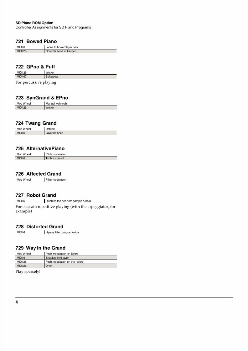
8/21/2019 MR_K2661
http://slidepdf.com/reader/full/mrk2661 458/499
4
SD Piano ROM Option
Controller Assignments for SD Piano Programs
721 Bowed Piano
722 GPno & Puff
For percussive playing
723 SynGrand & EPno
724 Twang Grand
725 AlternativePiano
726 Affected Grand
727 Robot Grand
For staccato repetitive playing (with the arpeggiator, forexample)
728 Distorted Grand
729 Way in the Grand
Play sparsely!
MIDI 6 Fades to bowed layer only
MIDI 25 Controls send to flanger
MIDI 25 Wetter
MIDI 67 Soft pedal
Mod Wheel Manual wah-wah
MIDI 25 Wetter
Mod Wheel Detune
MIDI 6 Layer balance
Mod Wheel Pitch modulation
MIDI 6 Timbre control
Mod Wheel Filter modulation
MIDI 6 Disables the per-note sample & hold
MIDI 6 Hipass filter, program-wide
Mod Wheel Pitch modulation on layers
MIDI 6 Enables third layer
MIDI 25 Pitch modulation on the reverb
MIDI 26 Drier
8/21/2019 MR_K2661
http://slidepdf.com/reader/full/mrk2661 459/499
Appendix G
Vintage Electric Pianos ROM Option
Objects for the Vintage Electric Pianos ROM are included on the SmartMedia card that came with your K2661. Theprocedure for installing these objects is described in the installation instructions that came with your option kit.
The Vintage Electric Pianos ROM option equips your K2661 with the classic electric piano sounds that are vital toany modern keyboard player. While some electric piano sounds have remained obscure vintage gems, others haveattained a level of importance to the keyboardist comparable to that which the Fender Stratocaster or Gibson LesPaul has for the modern guitarist.
Program slots have been assigned and organized for optimum usefulness. The instruments represented in this setare: Fender Rhodes Electric Piano, Wurlitzer Electric Piano, Hohner Pianet, Yamaha CP-80 Electric Grand Piano,and the RMI Electra-Piano.
Each program was created using high-quality audio samples of electric pianos as a starting point. The sounds werethen processed using Kurzweil’s V.A.S.T. synthesis engine. This allowed us to apply powerful filters, velocitylayers and cross-fades, envelopes and a host of other sound-sculpting tools. In some cases, samples from theK2661’s base-ROM were also used in combination with the Vintage EPs samples in order to add a certain flavor orto enhance the harmonic content of the sound.
The final stage of sound-shaping was done in KDFX, our massive effects processing engine. KDFX played a crucialrole in making this a truly ground-breaking project, providing on-board effects unprecedented in both quantityand quality. Effects pedals, speaker cabinets, and recording techniques have all been faithfully replicated, givingthe Vintage EPs programs a level of detail and realism never before achieved in any electric piano emulation.
Using V.A.S.T. and KDFX we were able to replicate the exact sounds from dozens of different live and studio
recordings of electric pianos. This is why many of the program names in Vintage EPs are derived from song titlesand not electric piano model numbers. Also, we have included a section devoted entirely to non-realistic sounds,“hybrids and synths,” where we transformed the Vintage EPs sound sources into a wide variety of sonic textures,ranging from slight mutations to completely unrecognizable new sounds.
We have included detailed charts that list the controller assignments for each program and setup. If a program has been taken from a specific recording, the artist's name and song title have been provided as well.
On the following pages are brief descriptions of each of the instruments sampled for Vintage EPs.
Program Farm Files
In addition to the 100 programs described on the following pages, we have included a number of other programsin the file EPFARM.K26. You can load these programs into the bank of your choice using the K2661’s Disk Mode.
8/21/2019 MR_K2661
http://slidepdf.com/reader/full/mrk2661 460/499
G-2
Vintage Electric Pianos ROM Option
Slider Assignments and KDFX
Here are a few of the guidelines which were used in determining control and slider assignments for the programsin Vintage EPs. These general rules should make it relatively easy to adjust the most basic program settings whenfirst scrolling and playing through the complete set of sounds. Keep in mind that these are general rules , and there
will be some exceptions. Refer to the table that begins on page G-5 to view the complete controller assignmentinformation for each program.
Many programs in the Vintage Electric Pianos ROM make extensive use of KDFX effects, and the programs weregreatly enhanced by the ability to “chain” multiple effects presets on a single KDFX bus. Thirty-one new KDFXstudios are included with Vintage EPs, and most of them use this powerful “effects-chaining” feature.
Since you can import studios from any program in the K2661, you may wish to use some of these new studios withother K2661 programs. To select a different studio for a program, press the ImpFX soft button while in program-edit mode, select a “target” program containing the desired effects studio, then press Import. This imports thetarget's studio along with all of the FX Mods of the target program. If it does not seem to work right away, go to theCommon page, and select a different KDFX pair (usually A or B) for the program.
8/21/2019 MR_K2661
http://slidepdf.com/reader/full/mrk2661 461/499
Vintage Electric Pianos ROM Option
G-3
Fender RhodesProduced from 1965-1986 in a number of variations of the original model, the Fender Rhodes isthe most widely recognized and easily identified electric piano sound in popular music. TheRhodes played an important role in defining some of the new styles of music that began to
emerge in the mid-sixties and early seventies, mainly jazz-fusion, disco and funk, and wasadopted quickly by other already established styles such as R&B, rock, pop, blues, and jazz. TheRhodes sound remains popular today and it can be found in a variety of settings: played live by blues, funk and jam bands among others, and on recordings of hip-hop, pop, acid-jazz, andelectronica.
Like most other electric pianos, the Rhodes produced its sound electromechanically, with ahammer mechanism striking metal bars or “tines.” A damper pedal, much like the one found onan acoustic piano, provided sustain.
The two main models (of which there were a few variations) were the Suitcase Piano and theStage Piano. The suitcase model was introduced first. Featuring an enclosure equipped with anamplifier, speaker cabinet, and tremolo circuit, the original suitcase model used hammers withfelt tips, which were later replaced by ones with neoprene (hard synthetic rubber) tips. The felt
hammers gave the early suitcase models a slightly less-bright attack sound and a less-tightdecay for each note. The Stage Piano (which did not have an amplifier nor speaker cabinet) wasintroduced in the early seventies as a more portable alternative to the Suitcase model. Bothmodels were replaced in 1979 by corresponding “Mark II” versions.
WurlitzerSimilar in both its design and sound to the Rhodes, the Wurlitzer electric piano was nearly aspopular, and actually pre-dated the first Rhodes suitcase model. Two basic models wereproduced, of which there were a few versions: the 100 series, manufactured from c.1954-1967,and the 200 series, which continued from c.1967-1980. Most recordings of the Wurlitzer featureone of the 200 series models.
Using a piano-type action with felt-tipped hammers to strike metal elements, called “reeds”, the
Wurlitzer employed a damper pedal mechanism to provide sustain, much the way the Rhodesdid. The Wurlitzer was smaller than the Rhodes (most had 64 notes), and was availableexclusively as a console, which sat on four metal legs. Most models came equipped with at leasttwo built-in speakers, and a tremolo circuit. The Wurlitzer produced a sound which had aslightly more narrow frequency range than the Rhodes; it was “thinner” sounding, blendingmore easily with other instruments in a mix.
Hohner PianetAlthough featured prominently in a number of classic rock songs by The Beatles, The Zombiesand others, the Hohner Pianet remains a lesser-known instrument, its sound having often beenmistakenly attributed to the Wurlitzer.
Produced from c.1962-1980 in various console models, the Pianet series differed from the
Rhodes and Wurlitzer in a few important areas. Sound was produced by metal reeds, whichwere plucked by a set of adhesive pads. Also distinguishing the Pianet was the absence of asustain pedal.
Hohner also manufactured the much more rare Electra-Piano (not to be confused with the RMIElectra-Piano) which featured an enclosure resembling that of an upright piano. Reported tohave a hammer mechanism very much like the one found in the Rhodes, the Hohner Electra-Piano featured a built-in amp and four speakers. Led Zeppelin made this sound famous,employing it in a number of hits. Using our Pianet samples and bit of processing, we were ableto craft some realistic imitations of the Hohner Electra-Piano, and we’ve included them in thePianet section of Vintage EPs.
8/21/2019 MR_K2661
http://slidepdf.com/reader/full/mrk2661 462/499
G-4
Vintage Electric Pianos ROM Option
Yamaha CP-80Known commonly as the “electric grand”, the CP-80 (88 notes), along with its smallercounterpart, the CP-70 (76 notes), was the product of clever engineering combined withtraditional piano-making craftsmanship. Inside the CP-80, are the basic workings of a real
acoustic piano, which have been altered to fit into a smaller enclosure. On the outside, the CP-80looks like a “grand” version of the Rhodes, covered in tolex, with the top portion extending inthe rear to accommodate the piano harp inside. Up until the mid-1980’s, when sampled pianos became available, the CP-70/80 was the only instrument capable of providing a decentsubstitute for a real piano. While it served this purpose well, the CP-70/80 had some uniquefeatures, which allowed it to have its own very distinct sound when desired.
With single strings on the lower notes, and double strings on the rest, the CP-70/80 included amodified Yamaha grand piano action and employed piezo-electric transducers in lieu ofpickups. The original CP series featured bass and treble tone controls and a tremolo circuit.Later, seven bands of EQ, balanced outputs and MIDI capabilities were added (CP-70/80B andM models). Often used with chorus and compression effects, the CP-80 was known for havingmore “punch” than an acoustic piano. Production began in 1977 and ended in 1987.
RMI Electra-PianoBuilt by Rocky Mount Instruments, a division of the Allen Organ Company, from 1967-1980, theRMI Electra-Piano is the one instrument represented in Vintage EPs which did not producesound by electromechanical means. With an electronic tone-generator for each note, un-weighted plastic keys, which were not touch-sensitive, and a set of “stops” for sound selection,the RMI more closely resembled an organ than anything else. Both sustain and volume pedalswere included with the unit. Most were black tolex-covered consoles with 61 (later 68) keys, andrested on a set of metal legs.
There were five stops on the RMI for tone: Piano, Piano PP, Harpsi, Harpsi PP, and Lute. Therewere two additional stops; Accenter, which added in an attack “thump” as well as Organ Mode,which extended the decay of held notes.
Though not capable of producing a realistic piano sound, the RMI, with its Harpsi stops didprovide a viable “electric harpsichord/clavichord” tone. In addition, the overall sound of theRMI was warm, yet thin and manageable, and lent itself nicely to the use of effects processorsand pedals. The RMI was most widely used by progressive-rock bands like Genesis and Yes inthe early to mid-1970s, although it has also appeared in a broad variety of other settings.
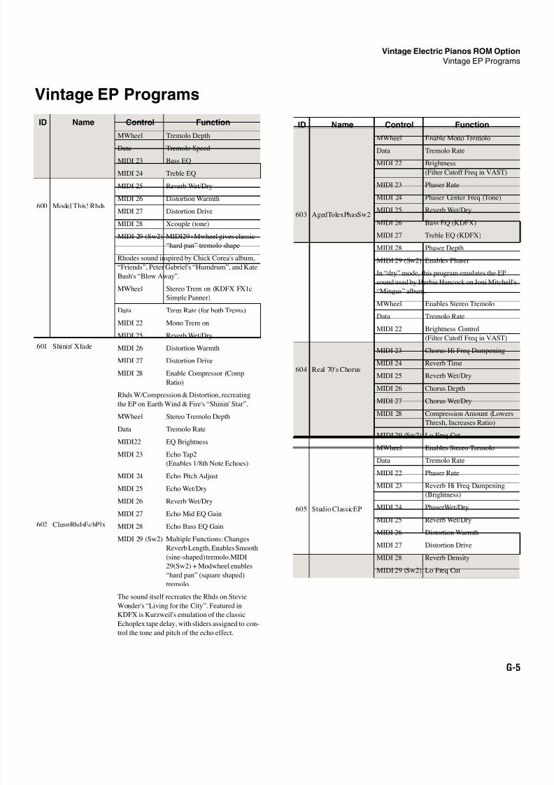
8/21/2019 MR_K2661
http://slidepdf.com/reader/full/mrk2661 463/499
Vintage Electric Pianos ROM Option
Vintage EP Programs
G-5
Vintage EP Programs
ID Name Control Function
600 Model This! Rhds
MWheel Tremolo DepthData Tremolo Speed
MIDI 23 Bass EQ
MIDI 24 Treble EQ
MIDI 25 Reverb Wet/Dry
MIDI 26 Distortion Warmth
MIDI 27 Distortion Drive
MIDI 28 Xcouple (tone)
MIDI 29 (Sw2) MIDI29+Mwheel gives classic
“hard pan” tremolo shape
Rhodes sound inspired by Chick Corea's album,
“Friends”, Peter Gabriel's “Humdrum”, and Kate
Bush's “Blow Away”.
601 Shinin' Xfade
MWheel Stereo Trem on (KDFX FX1c
Simple Panner)
Data Trem Rate (for both Trems)
MIDI 22 Mono Trem on
MIDI 25 Reverb Wet/Dry
MIDI 26 Distortion Warmth
MIDI 27 Distortion Drive
MIDI 28 Enable Compressor (Comp
Ratio)
Rhds W/Compression & Distortion, recreating
the EP on Earth Wind & Fire's “Shinin' Star”.
602 CleanRhdsEchPlx
MWheel Stereo Tremolo Depth
Data Tremolo Rate
MIDI22 EQ Brightness
MIDI 23 Echo Tap2
(Enables 1/8th Note Echoes)
MIDI 24 Echo Pitch Adjust
MIDI 25 Echo Wet/Dry
MIDI 26 Reverb Wet/Dry
MIDI 27 Echo Mid EQ Gain
MIDI 28 Echo Bass EQ Gain
MIDI 29 (Sw2) Multiple Functions: Changes
Reverb Length, Enables Smooth(sine-shaped) tremolo.MIDI
29(Sw2) + Modwheel enables
“hard pan” (square shaped)
tremolo.
The sound itself recreates the Rhds on Stevie
Wonder's “Living for the City”. Featured in
KDFX is Kurzweil's emulation of the classic
Echoplex tape delay, with sliders assigned to con-
trol the tone and pitch of the echo effect.
603 AgedTolexPhasSw2
MWheel Enable Mono Tremolo
Data Tremolo Rate
MIDI 22 Brightness
(Filter Cutoff Freq in VAST)
MIDI 23 Phaser Rate
MIDI 24 Phaser Center Freq (Tone)
MIDI 25 Reverb Wet/Dry
MIDI 26 Bass EQ (KDFX)
MIDI 27 Treble EQ (KDFX)
MIDI 28 Phaser Depth
MIDI 29 (Sw2) Enables Phaser
In “dry” mode, this program emulates the EPsound used by Herbie Hancock on Joni Mitchell's
“Mingus” album.
604 Real 70's Chorus
MWheel Enables Stereo Tremolo
Data Tremolo Rate
MIDI 22 Brightness Control
(Filter Cutoff Freq in VAST)
MIDI 23 Chorus Hi Freq Dampening
MIDI 24 Reverb Time
MIDI 25 Reverb Wet/Dry
MIDI 26 Chorus Depth
MIDI 27 Chorus Wet/Dry
MIDI 28 Compression Amount (LowersThresh, Increases Ratio)
MIDI 29 (Sw2) Lo Freq Cut
605 Studio ClassicEP
MWheel Enables Stereo Tremolo
Data Tremolo Rate
MIDI 22 Phaser Rate
MIDI 23 Reverb Hi Freq Dampening
(Brightness)
MIDI 24 PhaserWet/Dry
MIDI 25 Reverb Wet/Dry
MIDI 26 Distortion Warmth
MIDI 27 Distortion Drive
MIDI 28 Reverb Density
MIDI 29 (Sw2) Lo Freq Cut
ID Name Control Function
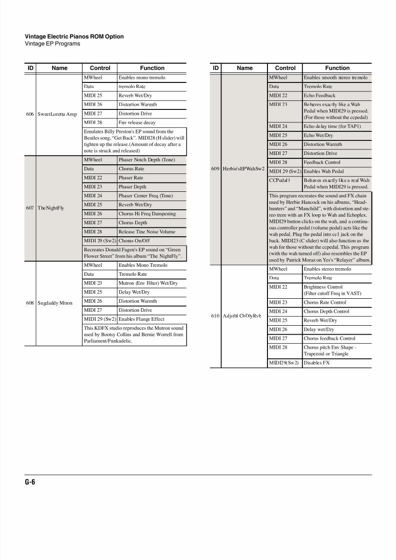
8/21/2019 MR_K2661
http://slidepdf.com/reader/full/mrk2661 464/499
G-6
Vintage Electric Pianos ROM Option
Vintage EP Programs
606 SweetLoretta Amp
MWheel Enables mono tremolo
Data tremolo Rate
MIDI 25 Reverb Wet/DryMIDI 26 Distortion Warmth
MIDI 27 Distortion Drive
MIDI 28 Env release decay
Emulates Billy Preston's EP sound from the
Beatles song, “Get Back”. MIDI28 (H slider) will
tighten up the release.(Amount of decay after a
note is struck and released)
607 TheNightFly
MWheel Phaser Notch Depth (Tone)
Data Chorus Rate
MIDI 22 Phaser Rate
MIDI 23 Phaser Depth
MIDI 24 Phaser Center Freq (Tone)
MIDI 25 Reverb Wet/Dry
MIDI 26 Chorus Hi Freq Dampening
MIDI 27 Chorus Depth
MIDI 28 Release Tine Noise Volume
MIDI 29 (Sw2) Chorus On/Off
Recreates Donald Fagen's EP sound on “Green
Flower Street” from his album “The NightFly”.
608 Sugdaddy Mtron
MWheel Enables Mono Tremolo
Data Tremolo Rate
MIDI 23 Mutron (Env Filter) Wet/Dry
MIDI 25 Delay Wet/DryMIDI 26 Distortion Warmth
MIDI 27 Distortion Drive
MIDI 29 (Sw2) Enables Flange Effect
This KDFX studio reproduces the Mutron sound
used by Bootsy Collins and Bernie Worrell from
Parliament/Funkadelic.
ID Name Control Function
609 Herbie'sEPWahSw2
MWheel Enables smooth stereo tremolo
Data Tremolo Rate
MIDI 22 Echo FeedbackMIDI 23 Behaves exactly like a Wah
Pedal when MIDI29 is pressed.
(For those without the ccpedal)
MIDI 24 Echo delay time (for TAP1)
MIDI 25 Echo Wet/Dry
MIDI 26 Distortion Warmth
MIDI 27 Distortion Drive
MIDI 28 Feedback Control
MIDI 29 (Sw2) Enables Wah Pedal
CCPedal1 Behaves exactly like a real Wah
Pedal when MIDI29 is pressed.
This program recreates the sound and FX chainused by Herbie Hancock on his albums, “Head-
hunters” and “Manchild”, with distortion and ste-
reo trem with an FX loop to Wah and Echoplex.
MIDI29 button clicks on the wah, and a continu-
ous controller pedal (volume pedal) acts like the
wah pedal. Plug the pedal into cc1 jack on the
back. MIDI23 (C slider) will also function as the
wah for those without the ccpedal. This program
(with the wah turned off) also resembles the EP
used by Patrick Moraz on Yes's “Relayer” album.
610 Adjstbl ChDlyRvb
MWheel Enables stereo tremolo
Data Tremolo Rate
MIDI 22 Brightness Control
(Filter cutoff Freq in VAST)
MIDI 23 Chorus Rate Control
MIDI 24 Chorus Depth Control
MIDI 25 Reverb Wet/Dry
MIDI 26 Delay wet/Dry
MIDI 27 Chorus feedback Control
MIDI 28 Chorus pitch Env Shape -
Trapezoid or Triangle
MIDI29(Sw2) Disables FX
ID Name Control Function
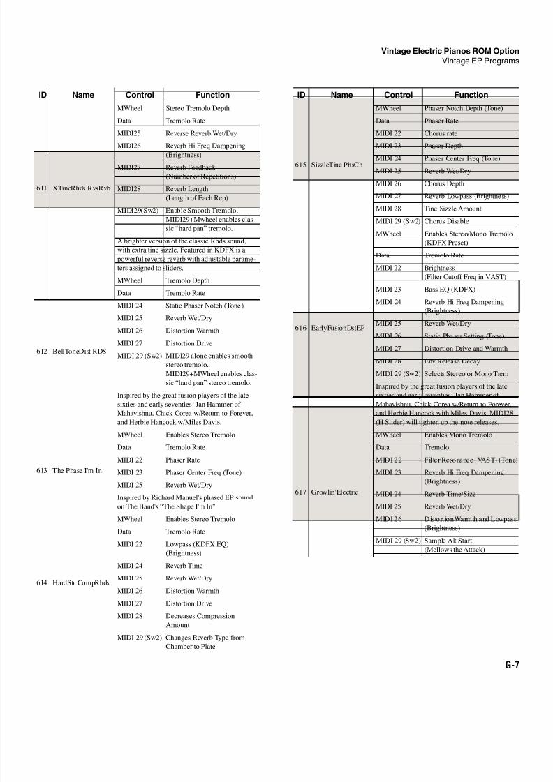
8/21/2019 MR_K2661
http://slidepdf.com/reader/full/mrk2661 465/499
Vintage Electric Pianos ROM Option
Vintage EP Programs
G-7
611 XTineRhds RvsRvb
MWheel Stereo Tremolo Depth
Data Tremolo Rate
MIDI25 Reverse Reverb Wet/DryMIDI26 Reverb Hi Freq Dampening
(Brightness)
MIDI27 Reverb Feedback
(Number of Repetitions)
MIDI28 Reverb Length
(Length of Each Rep)
MIDI29(Sw2) Enable Smooth Tremolo.
MIDI29+Mwheel enables clas-
sic “hard pan” tremolo.
A brighter version of the classic Rhds sound,
with extra tine sizzle. Featured in KDFX is a
powerful reverse reverb with adjustable parame-
ters assigned to sliders.
612 BellToneDist RDS
MWheel Tremolo Depth
Data Tremolo Rate
MIDI 24 Static Phaser Notch (Tone)
MIDI 25 Reverb Wet/Dry
MIDI 26 Distortion Warmth
MIDI 27 Distortion Drive
MIDI 29 (Sw2) MIDI29 alone enables smooth
stereo tremolo.
MIDI29+MWheel enables clas-
sic “hard pan” stereo tremolo.
Inspired by the great fusion players of the late
sixties and early seventies- Jan Hammer of
Mahavishnu, Chick Corea w/Return to Forever,
and Herbie Hancock w/Miles Davis.
613 The Phase I'm In
MWheel Enables Stereo Tremolo
Data Tremolo Rate
MIDI 22 Phaser Rate
MIDI 23 Phaser Center Freq (Tone)
MIDI 25 Reverb Wet/Dry
Inspired by Richard Manuel's phased EP sound
on The Band's “The Shape I'm In”
614 HardStr CompRhds
MWheel Enables Stereo Tremolo
Data Tremolo Rate
MIDI 22 Lowpass (KDFX EQ)
(Brightness)
MIDI 24 Reverb Time
MIDI 25 Reverb Wet/Dry
MIDI 26 Distortion Warmth
MIDI 27 Distortion Drive
MIDI 28 Decreases Compression
Amount
MIDI 29 (Sw2) Changes Reverb Type from
Chamber to Plate
ID Name Control Function
615 SizzleTine PhsCh
MWheel Phaser Notch Depth (Tone)
Data Phaser Rate
MIDI 22 Chorus rateMIDI 23 Phaser Depth
MIDI 24 Phaser Center Freq (Tone)
MIDI 25 Reverb Wet/Dry
MIDI 26 Chorus Depth
MIDI 27 Reverb Lowpass (Brightness)
MIDI 28 Tine Sizzle Amount
MIDI 29 (Sw2) Chorus Disable
616 EarlyFusionDstEP
MWheel Enables Stereo/Mono Tremolo
(KDFX Preset)
Data Tremolo Rate
MIDI 22 Brightness
(Filter Cutoff Freq in VAST)
MIDI 23 Bass EQ (KDFX)
MIDI 24 Reverb Hi Freq Dampening
(Brightness)
MIDI 25 Reverb Wet/Dry
MIDI 26 Static Phaser Setting (Tone)
MIDI 27 Distortion Drive and Warmth
MIDI 28 Env Release Decay
MIDI 29 (Sw2) Selects Stereo or Mono Trem
Inspired by the great fusion players of the late
sixties and early seventies- Jan Hammer of
Mahavishnu, Chick Corea w/Return to Forever,
and Herbie Hancock with Miles Davis. MIDI28
(H Slider) will tighten up the note releases.
617 Growlin'Electric
MWheel Enables Mono Tremolo
Data Tremolo
MIDI 22 Filter Resonance (VAST) (Tone)
MIDI 23 Reverb Hi Freq Dampening
(Brightness)
MIDI 24 Reverb Time/Size
MIDI 25 Reverb Wet/Dry
MIDI 26 Distort ion Warmth and Lowpass
(Brightness)
MIDI 29 (Sw2) Sample Alt Start
(Mellows the Attack)
ID Name Control Function
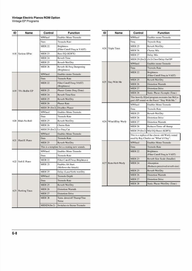
8/21/2019 MR_K2661
http://slidepdf.com/reader/full/mrk2661 466/499
G-8
Vintage Electric Pianos ROM Option
Vintage EP Programs
618 Serious EPno
MWheel Enables Mono Tremolo
Data Tremolo Rate
MIDI 22 Brightness(Filter Cutoff Freq in VAST)
MIDI 23 Bass EQ (KDFX)
MIDI 24 Reverb Time
MIDI 25 Reverb Wet/Dry
MIDI 26 Reverb Hi Freq Dampening
(Brightness)
619 70's HrdStr EP
MWheel Enables mono Tremolo
Data Tremolo Rate
MIDI 22 Filter Cutoff Freq (VAST)
(Brightness)
MIDI 23 Phaser Center Freq (Tone)
MIDI 24 Reverb Time/Size
MIDI 25 Reverb Wet/Dry
MIDI 26 Phaser Rate
MIDI 29 (Sw2) Disables Phaser
620 Rhds No Bell
MWheel Enables Mono Tremolo
Data Tremolo Rate
MIDI 25 Reverb Wet/Dry
MIDI 26 Chorus Rate
MIDI 29 (Sw2) Lo Freq Cut
621 Hard E Piano
MWheel Enables Mono Tremolo
Data Tremolo Rate
MIDI 25 Reverb Wet/Dry
This is a template for a creating new sounds.
622 Soft E Piano
MWheel Enables Mono Tremolo
Data Tremolo Rate
MIDI 22 Filter Cutoff Freq (Brightness)
MIDI 23 Enables Alt Start
(Mellows the Attack)
MIDI 25 Delay (LaserVerb) wet/Dry
623 Barking Tines
MWheel Tremolo Depth
Data Tremolo Rate
MIDI 25 Reverb Wet/Dry
MIDI 26 Distortion WarmthMIDI 27 Distortion Drive
MIDI 28 Turns down/off Thump/Tine
Noise
MIDI29(Sw2) Switches to Stereo Tremolo
ID Name Control Function
624 Triple Tines
MWheel Enables mono Tremolo
Data Tremolo Rate
MIDI 25 Reverb Wet/DryMIDI 26 Chorus Mix
MIDI 27 Delay Mix
MIDI 29 (Sw2) (fx3) Chor/Delay On/Off
625 Stay With Me
MWheel Enables mono Tremolo
Data Tremolo Rate
MIDI 22 Brightness
(Filter Cutoff Freq in VAST)
MIDI 25 Reverb Wet/Dry
MIDI 26 Distortion Warmth
MIDI 27 Distortion Drive
MIDI 28 Static Phaser Xcouple (Tone)
This heavily EQed program recreates Ian McLa-
gan's EP sound on the Faces' “Stay With Me.”
626 What'dISay Wurly
MWheel Enables Mono Tremolo
Data Tremolo Rate
MIDI 25 Reverb Wet/Dry
MIDI 26 Distortion Drive
MIDI 27 Distortion Warmth
MIDI 28 Reduces/Turns off thump
MIDI 29 (Sw2) Mid EQ Boost (KDFX)
This is a replica of the classic old Wurly sound
used by Ray Charles on “What’d I Say”.
627 RetroVerb Wurly
MWheel Enables Mono Tremolo
Data Tremolo Rate
MIDI 22 Brightness
(Filter Cutoff Freq in VAST)
MIDI 23 Reverb Size Scale (Smaller)
MIDI 24 Absorption
(Reduces perceived reverb size)
MIDI 25 Reverb Wet/Dry
MIDI 26 Distortion Warmth
MIDI 27 Distortion Drive
MIDI 28 Static Phaser Wet/Dry (Tone)
ID Name Control Function
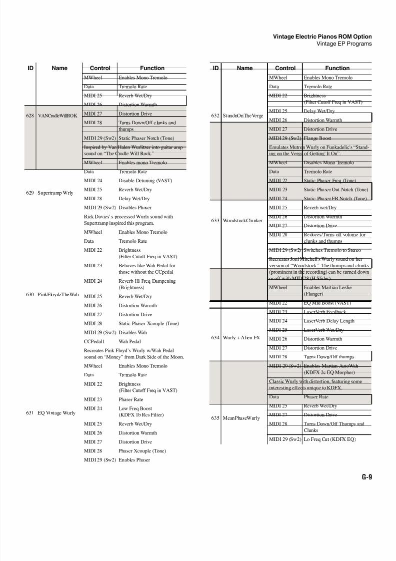
8/21/2019 MR_K2661
http://slidepdf.com/reader/full/mrk2661 467/499
Vintage Electric Pianos ROM Option
Vintage EP Programs
G-9
628 VANCradleWillROK
MWheel Enables Mono Tremolo
Data Tremolo Rate
MIDI 25 Reverb Wet/DryMIDI 26 Distortion Warmth
MIDI 27 Distortion Drive
MIDI 28 Turns Down/Off clunks and
thumps
MIDI 29 (Sw2) Static Phaser Notch (Tone)
Inspired by Van Halen Wurlitzer into guitar amp
sound on “The Cradle Will Rock.”
629 Supertramp Wrly
MWheel Enables mono Tremolo
Data Tremolo Rate
MIDI 24 Disable Detuning (VAST)
MIDI 25 Reverb Wet/Dry
MIDI 28 Delay Wet/Dry
MIDI 29 (Sw2) Disables Phaser
Rick Davies' s processed Wurly sound with
Supertramp inspired this program.
630 PinkFloydzTheWah
MWheel Enables Mono Tremolo
Data Tremolo Rate
MIDI 22 Brightness
(Filter Cutoff Freq in VAST)
MIDI 23 Behaves like Wah Pedal for
those without the CCpedal
MIDI 24 Reverb Hi Freq Dampening
(Brightness)
MIDI 25 Reverb Wet/Dry
MIDI 26 Distortion Warmth
MIDI 27 Distortion Drive
MIDI 28 Static Phaser Xcouple (Tone)
MIDI 29 (Sw2) Disables Wah
CCPedal1 Wah Pedal
Recreates Pink Floyd’s Wurly w/Wah Pedal
sound on “Money” from Dark Side of the Moon.
631 EQ Vintage Wurly
MWheel Enables Mono Tremolo
Data Tremolo Rate
MIDI 22 Brightness
(Filter Cutoff Freq in VAST)
MIDI 23 Phaser Rate
MIDI 24 Low Freq Boost
(KDFX 1b Res Filter)
MIDI 25 Reverb Wet/Dry
MIDI 26 Distortion Warmth
MIDI 27 Distortion Drive
MIDI 28 Phaser Xcouple (Tone)
MIDI 29 (Sw2) Enables Phaser
ID Name Control Function
632 StandnOnTheVerge
MWheel Enables Mono Tremolo
Data Tremolo Rate
MIDI 22 Brightness(Filter Cutoff Freq in VAST)
MIDI 25 Delay Wet/Dry
MIDI 26 Distortion Warmth
MIDI 27 Distortion Drive
MIDI 29 (Sw2) Flange Boost
Emulates Mutron Wurly on Funkadelic's “Stand-
ing on the Verge of Getting' It On”.
633 WoodstockClunker
MWheel Disables Mono Tremolo
Data Tremolo Rate
MIDI 22 Static Phaser Freq (Tone)
MIDI 23 Static Phaser Out Notch (Tone)
MIDI 24 Static Phaser FB Notch (Tone)
MIDI 25 Reverb wet/Dry
MIDI 26 Distortion Warmth
MIDI 27 Distortion Drive
MIDI 28 Reduces/Turns off volume for
clunks and thumps
MIDI 29 (Sw2) Switches Tremolo to Stereo
Recreates Joni Mitchell's Wurly sound on her
version of “Woodstock”. The thumps and clunks
(prominent in the recording) can be turned down
or off with MIDI28 (H Slider).
634 Wurly + Alien FX
MWheel Enables Martian Leslie
(Flanger)
MIDI 22 EQ Mid Boost (VAST)
MIDI 23 LaserVerb Feedback
MIDI 24 LaserVerb Delay Length
MIDI 25 LaserVerb Wet/Dry
MIDI 26 Distortion Warmth
MIDI 27 Distortion Drive
MIDI 28 Turns Down/Off thumps
MIDI 29 (Sw2) Enables Martian AutoWah
(KDFX 2c EQ Morpher)
Classic Wurly with distortion, featuring some
interesting effects unique to KDFX.
635 MeanPhaseWurly
Data Phaser Rate
MIDI 25 Reverb Wet/Dry
MIDI 27 Distortion Drive
MIDI 28 Turns Down/Off Thumps and
Clunks
MIDI 29 (Sw2) Lo Freq Cut (KDFX EQ)
ID Name Control Function
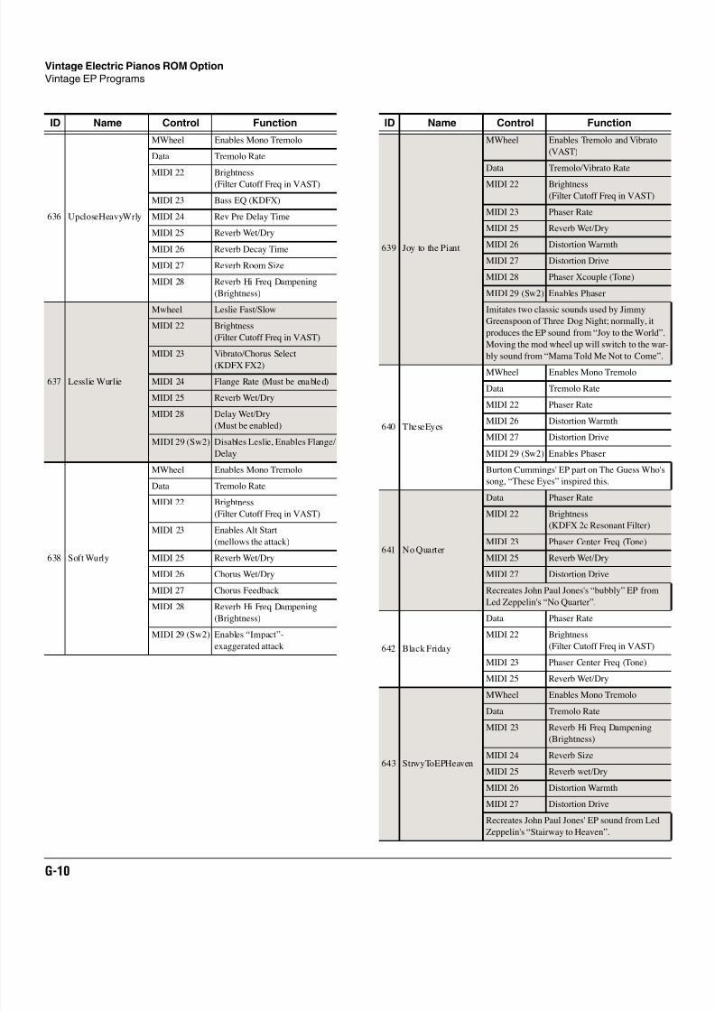
8/21/2019 MR_K2661
http://slidepdf.com/reader/full/mrk2661 468/499
G-10
Vintage Electric Pianos ROM Option
Vintage EP Programs
636 UpcloseHeavyWrly
MWheel Enables Mono Tremolo
Data Tremolo Rate
MIDI 22 Brightness(Filter Cutoff Freq in VAST)
MIDI 23 Bass EQ (KDFX)
MIDI 24 Rev Pre Delay Time
MIDI 25 Reverb Wet/Dry
MIDI 26 Reverb Decay Time
MIDI 27 Reverb Room Size
MIDI 28 Reverb Hi Freq Dampening
(Brightness)
637 Lesslie Wurlie
Mwheel Leslie Fast/Slow
MIDI 22 Brightness
(Filter Cutoff Freq in VAST)
MIDI 23 Vibrato/Chorus Select(KDFX FX2)
MIDI 24 Flange Rate (Must be enabled)
MIDI 25 Reverb Wet/Dry
MIDI 28 Delay Wet/Dry
(Must be enabled)
MIDI 29 (Sw2) Disables Leslie, Enables Flange/
Delay
638 Soft Wurly
MWheel Enables Mono Tremolo
Data Tremolo Rate
MIDI 22 Brightness
(Filter Cutoff Freq in VAST)
MIDI 23 Enables Alt Start(mellows the attack)
MIDI 25 Reverb Wet/Dry
MIDI 26 Chorus Wet/Dry
MIDI 27 Chorus Feedback
MIDI 28 Reverb Hi Freq Dampening
(Brightness)
MIDI 29 (Sw2) Enables “Impact”-
exaggerated attack
ID Name Control Function
639 Joy to the Piant
MWheel Enables Tremolo and Vibrato
(VAST)
Data Tremolo/Vibrato Rate
MIDI 22 Brightness
(Filter Cutoff Freq in VAST)
MIDI 23 Phaser Rate
MIDI 25 Reverb Wet/Dry
MIDI 26 Distortion Warmth
MIDI 27 Distortion Drive
MIDI 28 Phaser Xcouple (Tone)
MIDI 29 (Sw2) Enables Phaser
Imitates two classic sounds used by Jimmy
Greenspoon of Three Dog Night; normally, it
produces the EP sound from “Joy to the World”.
Moving the mod wheel up will switch to the war-
bly sound from “Mama Told Me Not to Come”.
640 TheseEyes
MWheel Enables Mono Tremolo
Data Tremolo Rate
MIDI 22 Phaser Rate
MIDI 26 Distortion Warmth
MIDI 27 Distortion Drive
MIDI 29 (Sw2) Enables Phaser
Burton Cummings' EP part on The Guess Who's
song, “These Eyes” inspired this.
641 No Quarter
Data Phaser Rate
MIDI 22 Brightness
(KDFX 2c Resonant Filter)
MIDI 23 Phaser Center Freq (Tone)
MIDI 25 Reverb Wet/Dry
MIDI 27 Distortion Drive
Recreates John Paul Jones's “bubbly” EP from
Led Zeppelin's “No Quarter”.
642 Black Friday
Data Phaser Rate
MIDI 22 Brightness
(Filter Cutoff Freq in VAST)
MIDI 23 Phaser Center Freq (Tone)
MIDI 25 Reverb Wet/Dry
643 StrwyToEPHeaven
MWheel Enables Mono Tremolo
Data Tremolo Rate
MIDI 23 Reverb Hi Freq Dampening
(Brightness)
MIDI 24 Reverb Size
MIDI 25 Reverb wet/Dry
MIDI 26 Distortion Warmth
MIDI 27 Distortion Drive
Recreates John Paul Jones' EP sound from Led
Zeppelin's “Stairway to Heaven”.
ID Name Control Function
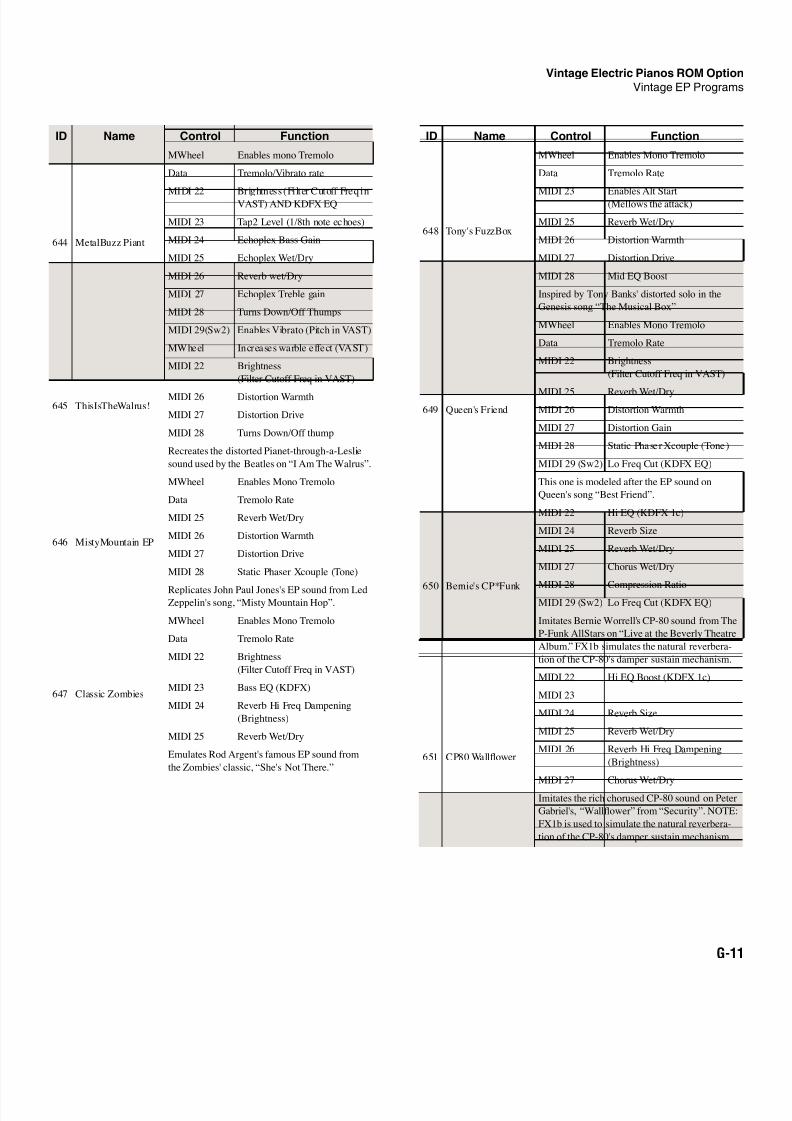
8/21/2019 MR_K2661
http://slidepdf.com/reader/full/mrk2661 469/499
Vintage Electric Pianos ROM Option
Vintage EP Programs
G-11
644 MetalBuzz Piant
MWheel Enables mono Tremolo
Data Tremolo/Vibrato rate
MIDI 22 Brightness (Filter Cutoff Freq inVAST) AND KDFX EQ
MIDI 23 Tap2 Level (1/8th note echoes)
MIDI 24 Echoplex Bass Gain
MIDI 25 Echoplex Wet/Dry
MIDI 26 Reverb wet/Dry
MIDI 27 Echoplex Treble gain
MIDI 28 Turns Down/Off Thumps
MIDI 29(Sw2) Enables Vibrato (Pitch in VAST)
645 ThisIsTheWalrus!
MWheel Increases warble effect (VAST)
MIDI 22 Brightness
(Filter Cutoff Freq in VAST)
MIDI 26 Distortion Warmth
MIDI 27 Distortion Drive
MIDI 28 Turns Down/Off thump
Recreates the distorted Pianet-through-a-Leslie
sound used by the Beatles on “I Am The Walrus”.
646 MistyMountain EP
MWheel Enables Mono Tremolo
Data Tremolo Rate
MIDI 25 Reverb Wet/Dry
MIDI 26 Distortion Warmth
MIDI 27 Distortion Drive
MIDI 28 Static Phaser Xcouple (Tone)
Replicates John Paul Jones's EP sound from LedZeppelin's song, “Misty Mountain Hop”.
647 Classic Zombies
MWheel Enables Mono Tremolo
Data Tremolo Rate
MIDI 22 Brightness
(Filter Cutoff Freq in VAST)
MIDI 23 Bass EQ (KDFX)
MIDI 24 Reverb Hi Freq Dampening
(Brightness)
MIDI 25 Reverb Wet/Dry
Emulates Rod Argent's famous EP sound from
the Zombies' classic, “She's Not There.”
ID Name Control Function
648 Tony's FuzzBox
MWheel Enables Mono Tremolo
Data Tremolo Rate
MIDI 23 Enables Alt Start(Mellows the attack)
MIDI 25 Reverb Wet/Dry
MIDI 26 Distortion Warmth
MIDI 27 Distortion Drive
MIDI 28 Mid EQ Boost
Inspired by Tony Banks' distorted solo in the
Genesis song “The Musical Box”
649 Queen's Friend
MWheel Enables Mono Tremolo
Data Tremolo Rate
MIDI 22 Brightness
(Filter Cutoff Freq in VAST)
MIDI 25 Reverb Wet/Dry
MIDI 26 Distortion Warmth
MIDI 27 Distortion Gain
MIDI 28 Static Phaser Xcouple (Tone)
MIDI 29 (Sw2) Lo Freq Cut (KDFX EQ)
This one is modeled after the EP sound on
Queen's song “Best Friend”.
650 Bernie's CP*Funk
MIDI 22 Hi EQ (KDFX 1c)
MIDI 24 Reverb Size
MIDI 25 Reverb Wet/Dry
MIDI 27 Chorus Wet/Dry
MIDI 28 Compression RatioMIDI 29 (Sw2) Lo Freq Cut (KDFX EQ)
Imitates Bernie Worrell's CP-80 sound from The
P-Funk AllStars on “Live at the Beverly Theatre
Album.” FX1b simulates the natural reverbera-
tion of the CP-80's damper sustain mechanism.
651 CP80 Wallflower
MIDI 22 Hi EQ Boost (KDFX 1c)
MIDI 23
MIDI 24 Reverb Size
MIDI 25 Reverb Wet/Dry
MIDI 26 Reverb Hi Freq Dampening
(Brightness)
MIDI 27 Chorus Wet/Dry
Imitates the rich chorused CP-80 sound on Peter
Gabriel's, “Wallflower” from “Security”. NOTE:
FX1b is used to simulate the natural reverbera-
tion of the CP-80's damper sustain mechanism.
ID Name Control Function
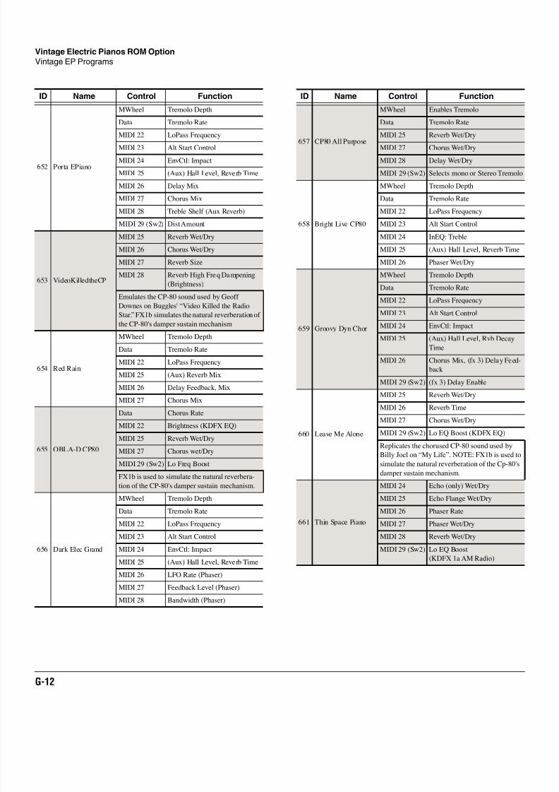
8/21/2019 MR_K2661
http://slidepdf.com/reader/full/mrk2661 470/499
G-12
Vintage Electric Pianos ROM Option
Vintage EP Programs
652 Porta EPiano
MWheel Tremolo Depth
Data Tremolo Rate
MIDI 22 LoPass FrequencyMIDI 23 Alt Start Control
MIDI 24 EnvCtl: Impact
MIDI 25 (Aux) Hall Level, Reverb Time
MIDI 26 Delay Mix
MIDI 27 Chorus Mix
MIDI 28 Treble Shelf (Aux Reverb)
MIDI 29 (Sw2) Dist Amount
653 VideoKilledtheCP
MIDI 25 Reverb Wet/Dry
MIDI 26 Chorus Wet/Dry
MIDI 27 Reverb Size
MIDI 28 Reverb High Freq Dampening(Brightness)
Emulates the CP-80 sound used by Geoff
Downes on Buggles' “Video Killed the Radio
Star.” FX1b simulates the natural reverberation of
the CP-80's damper sustain mechanism
654 Red Rain
MWheel Tremolo Depth
Data Tremolo Rate
MIDI 22 LoPass Frequency
MIDI 25 (Aux) Reverb Mix
MIDI 26 Delay Feedback, Mix
MIDI 27 Chorus Mix
655 OBLA-D CP80
Data Chorus RateMIDI 22 Brightness (KDFX EQ)
MIDI 25 Reverb Wet/Dry
MIDI 27 Chorus wet/Dry
MIDI 29 (Sw2) Lo Freq Boost
FX1b is used to simulate the natural reverbera-
tion of the CP-80's damper sustain mechanism.
656 Dark Elec Grand
MWheel Tremolo Depth
Data Tremolo Rate
MIDI 22 LoPass Frequency
MIDI 23 Alt Start Control
MIDI 24 EnvCtl: Impact
MIDI 25 (Aux) Hall Level, Reverb Time
MIDI 26 LFO Rate (Phaser)
MIDI 27 Feedback Level (Phaser)
MIDI 28 Bandwidth (Phaser)
ID Name Control Function
657 CP80 All Purpose
MWheel Enables Tremolo
Data Tremolo Rate
MIDI 25 Reverb Wet/DryMIDI 27 Chorus Wet/Dry
MIDI 28 Delay Wet/Dry
MIDI 29 (Sw2) Selects mono or Stereo Tremolo
658 Bright Live CP80
MWheel Tremolo Depth
Data Tremolo Rate
MIDI 22 LoPass Frequency
MIDI 23 Alt Start Control
MIDI 24 InEQ: Treble
MIDI 25 (Aux) Hall Level, Reverb Time
MIDI 26 Phaser Wet/Dry
659 Groovy Dyn Chor
MWheel Tremolo DepthData Tremolo Rate
MIDI 22 LoPass Frequency
MIDI 23 Alt Start Control
MIDI 24 EnvCtl: Impact
MIDI 25 (Aux) Hall Level, Rvb Decay
Time
MIDI 26 Chorus Mix, (fx 3) Delay Feed-
back
MIDI 29 (Sw2) (fx 3) Delay Enable
660 Leave Me Alone
MIDI 25 Reverb Wet/Dry
MIDI 26 Reverb Time
MIDI 27 Chorus Wet/Dry
MIDI 29 (Sw2) Lo EQ Boost (KDFX EQ)
Replicates the chorused CP-80 sound used by
Billy Joel on “My Life”. NOTE: FX1b is used to
simulate the natural reverberation of the Cp-80's
damper sustain mechanism.
661 Thin Space Piano
MIDI 24 Echo (only) Wet/Dry
MIDI 25 Echo Flange Wet/Dry
MIDI 26 Phaser Rate
MIDI 27 Phaser Wet/Dry
MIDI 28 Reverb Wet/Dry
MIDI 29 (Sw2) Lo EQ Boost
(KDFX 1a AM Radio)
ID Name Control Function
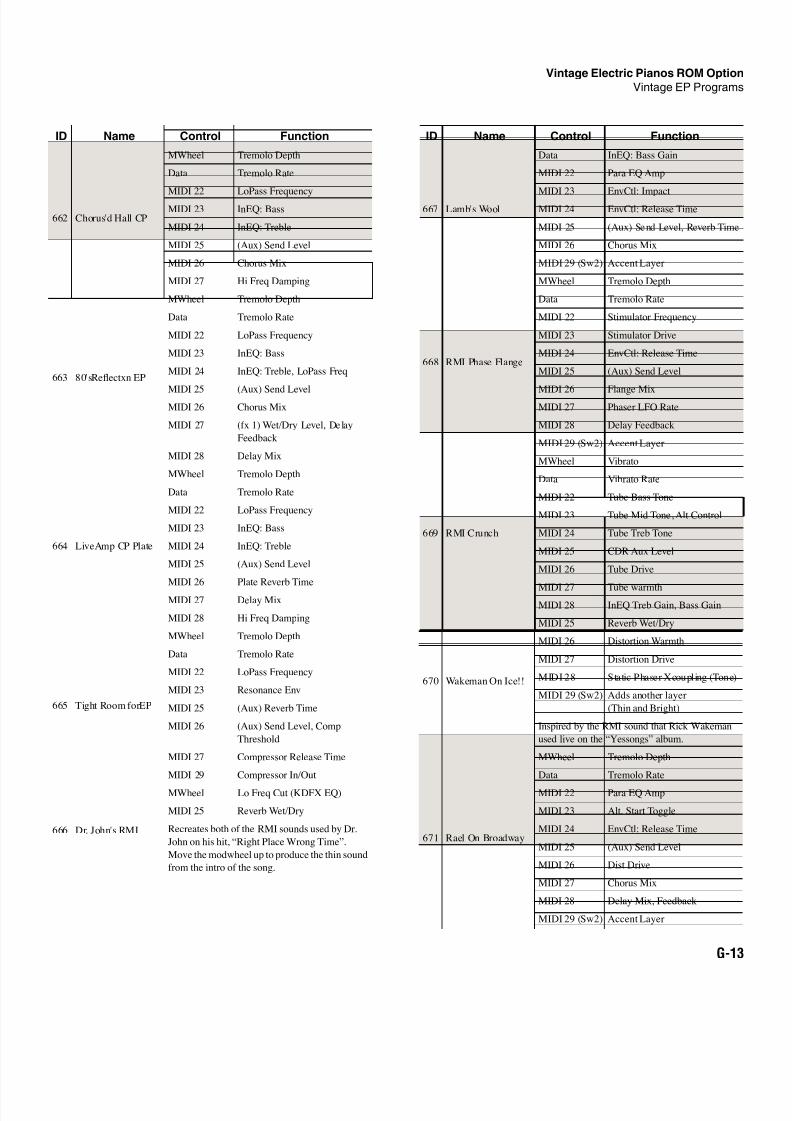
8/21/2019 MR_K2661
http://slidepdf.com/reader/full/mrk2661 471/499
Vintage Electric Pianos ROM Option
Vintage EP Programs
G-13
662 Chorus'd Hall CP
MWheel Tremolo Depth
Data Tremolo Rate
MIDI 22 LoPass FrequencyMIDI 23 InEQ: Bass
MIDI 24 InEQ: Treble
MIDI 25 (Aux) Send Level
MIDI 26 Chorus Mix
MIDI 27 Hi Freq Damping
663 80'sReflectxn EP
MWheel Tremolo Depth
Data Tremolo Rate
MIDI 22 LoPass Frequency
MIDI 23 InEQ: Bass
MIDI 24 InEQ: Treble, LoPass Freq
MIDI 25 (Aux) Send LevelMIDI 26 Chorus Mix
MIDI 27 (fx 1) Wet/Dry Level, Delay
Feedback
MIDI 28 Delay Mix
664 LiveAmp CP Plate
MWheel Tremolo Depth
Data Tremolo Rate
MIDI 22 LoPass Frequency
MIDI 23 InEQ: Bass
MIDI 24 InEQ: Treble
MIDI 25 (Aux) Send Level
MIDI 26 Plate Reverb Time
MIDI 27 Delay Mix
MIDI 28 Hi Freq Damping
665 Tight Room forEP
MWheel Tremolo Depth
Data Tremolo Rate
MIDI 22 LoPass Frequency
MIDI 23 Resonance Env
MIDI 25 (Aux) Reverb Time
MIDI 26 (Aux) Send Level, Comp
Threshold
MIDI 27 Compressor Release Time
MIDI 29 Compressor In/Out
666 Dr. John's RMI
MWheel Lo Freq Cut (KDFX EQ)
MIDI 25 Reverb Wet/Dry
Recreates both of the RMI sounds used by Dr.
John on his hit, “Right Place Wrong Time”.
Move the modwheel up to produce the thin sound
from the intro of the song.
ID Name Control Function
667 Lamb's Wool
Data InEQ: Bass Gain
MIDI 22 Para EQ Amp
MIDI 23 EnvCtl: ImpactMIDI 24 EnvCtl: Release Time
MIDI 25 (Aux) Send Level, Reverb Time
MIDI 26 Chorus Mix
MIDI 29 (Sw2) Accent Layer
668 RMI Phase Flange
MWheel Tremolo Depth
Data Tremolo Rate
MIDI 22 Stimulator Frequency
MIDI 23 Stimulator Drive
MIDI 24 EnvCtl: Release Time
MIDI 25 (Aux) Send Level
MIDI 26 Flange MixMIDI 27 Phaser LFO Rate
MIDI 28 Delay Feedback
MIDI 29 (Sw2) Accent Layer
669 RMI Crunch
MWheel Vibrato
Data Vibrato Rate
MIDI 22 Tube Bass Tone
MIDI 23 Tube Mid Tone, Alt Control
MIDI 24 Tube Treb Tone
MIDI 25 CDR Aux Level
MIDI 26 Tube Drive
MIDI 27 Tube warmth
MIDI 28 InEQ Treb Gain, Bass Gain
670 Wakeman On Ice!!
MIDI 25 Reverb Wet/Dry
MIDI 26 Distortion Warmth
MIDI 27 Distortion Drive
MIDI 28 Static Phaser Xcoupling (Tone)
MIDI 29 (Sw2) Adds another layer
(Thin and Bright)
Inspired by the RMI sound that Rick Wakeman
used live on the “Yessongs” album.
671 Rael On Broadway
MWheel Tremolo Depth
Data Tremolo Rate
MIDI 22 Para EQ Amp
MIDI 23 Alt. Start Toggle
MIDI 24 EnvCtl: Release Time
MIDI 25 (Aux) Send Level
MIDI 26 Dist Drive
MIDI 27 Chorus Mix
MIDI 28 Delay Mix, Feedback
MIDI 29 (Sw2) Accent Layer
ID Name Control Function
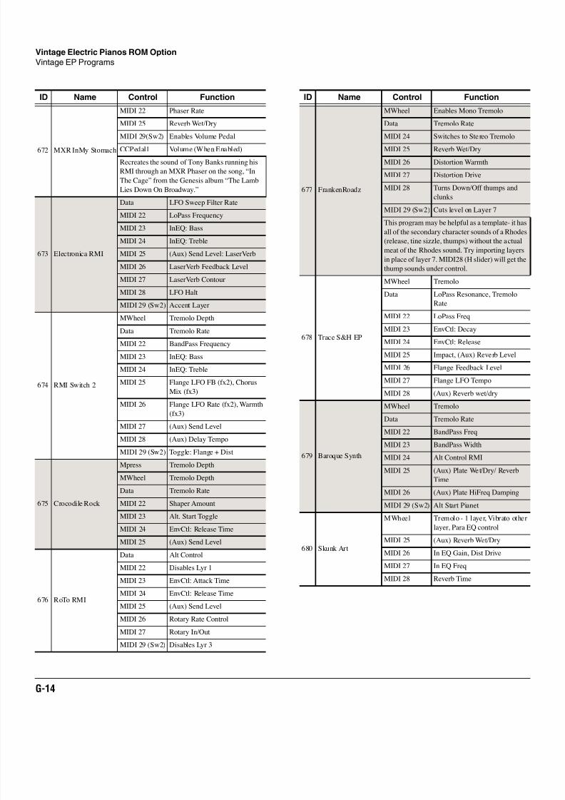
8/21/2019 MR_K2661
http://slidepdf.com/reader/full/mrk2661 472/499
G-14
Vintage Electric Pianos ROM Option
Vintage EP Programs
672 MXR InMy Stomach
MIDI 22 Phaser Rate
MIDI 25 Reverb Wet/Dry
MIDI 29(Sw2) Enables Volume PedalCCPedal1 Volume (When Enabled)
Recreates the sound of Tony Banks running his
RMI through an MXR Phaser on the song, “In
The Cage” from the Genesis album “The Lamb
Lies Down On Broadway.”
673 Electronica RMI
Data LFO Sweep Filter Rate
MIDI 22 LoPass Frequency
MIDI 23 InEQ: Bass
MIDI 24 InEQ: Treble
MIDI 25 (Aux) Send Level: LaserVerb
MIDI 26 LaserVerb Feedback Level
MIDI 27 LaserVerb Contour
MIDI 28 LFO Halt
MIDI 29 (Sw2) Accent Layer
674 RMI Switch 2
MWheel Tremolo Depth
Data Tremolo Rate
MIDI 22 BandPass Frequency
MIDI 23 InEQ: Bass
MIDI 24 InEQ: Treble
MIDI 25 Flange LFO FB (fx2), Chorus
Mix (fx3)
MIDI 26 Flange LFO Rate (fx2), Warmth
(fx3)
MIDI 27 (Aux) Send Level
MIDI 28 (Aux) Delay Tempo
MIDI 29 (Sw2) Toggle: Flange + Dist
675 Crocodile Rock
Mpress Tremolo Depth
MWheel Tremolo Depth
Data Tremolo Rate
MIDI 22 Shaper Amount
MIDI 23 Alt. Start Toggle
MIDI 24 EnvCtl: Release Time
MIDI 25 (Aux) Send Level
676 RoTo RMI
Data Alt Control
MIDI 22 Disables Lyr 1
MIDI 23 EnvCtl: Attack Time
MIDI 24 EnvCtl: Release Time
MIDI 25 (Aux) Send Level
MIDI 26 Rotary Rate Control
MIDI 27 Rotary In/Out
MIDI 29 (Sw2) Disables Lyr 3
ID Name Control Function
677 FrankenRoadz
MWheel Enables Mono Tremolo
Data Tremolo Rate
MIDI 24 Switches to Stereo TremoloMIDI 25 Reverb Wet/Dry
MIDI 26 Distortion Warmth
MIDI 27 Distortion Drive
MIDI 28 Turns Down/Off thumps and
clunks
MIDI 29 (Sw2) Cuts level on Layer 7
This program may be helpful as a template- it has
all of the secondary character sounds of a Rhodes
(release, tine sizzle, thumps) without the actual
meat of the Rhodes sound. Try importing layers
in place of layer 7. MIDI28 (H slider) will get the
thump sounds under control.
678 Trace S&H EP
MWheel Tremolo
Data LoPass Resonance, Tremolo
Rate
MIDI 22 LoPass Freq
MIDI 23 EnvCtl: Decay
MIDI 24 EnvCtl: Release
MIDI 25 Impact, (Aux) Reverb Level
MIDI 26 Flange Feedback Level
MIDI 27 Flange LFO Tempo
MIDI 28 (Aux) Reverb wet/dry
679 Baroque Synth
MWheel Tremolo
Data Tremolo Rate
MIDI 22 BandPass Freq
MIDI 23 BandPass Width
MIDI 24 Alt Control RMI
MIDI 25 (Aux) Plate Wet/Dry/ Reverb
Time
MIDI 26 (Aux) Plate HiFreq Damping
MIDI 29 (Sw2) Alt Start Pianet
680 Skunk Art
MWheel Tremolo - 1 layer, Vibrato other
layer, Para EQ control
MIDI 25 (Aux) Reverb Wet/Dry
MIDI 26 In EQ Gain, Dist Drive
MIDI 27 In EQ Freq
MIDI 28 Reverb Time
ID Name Control Function
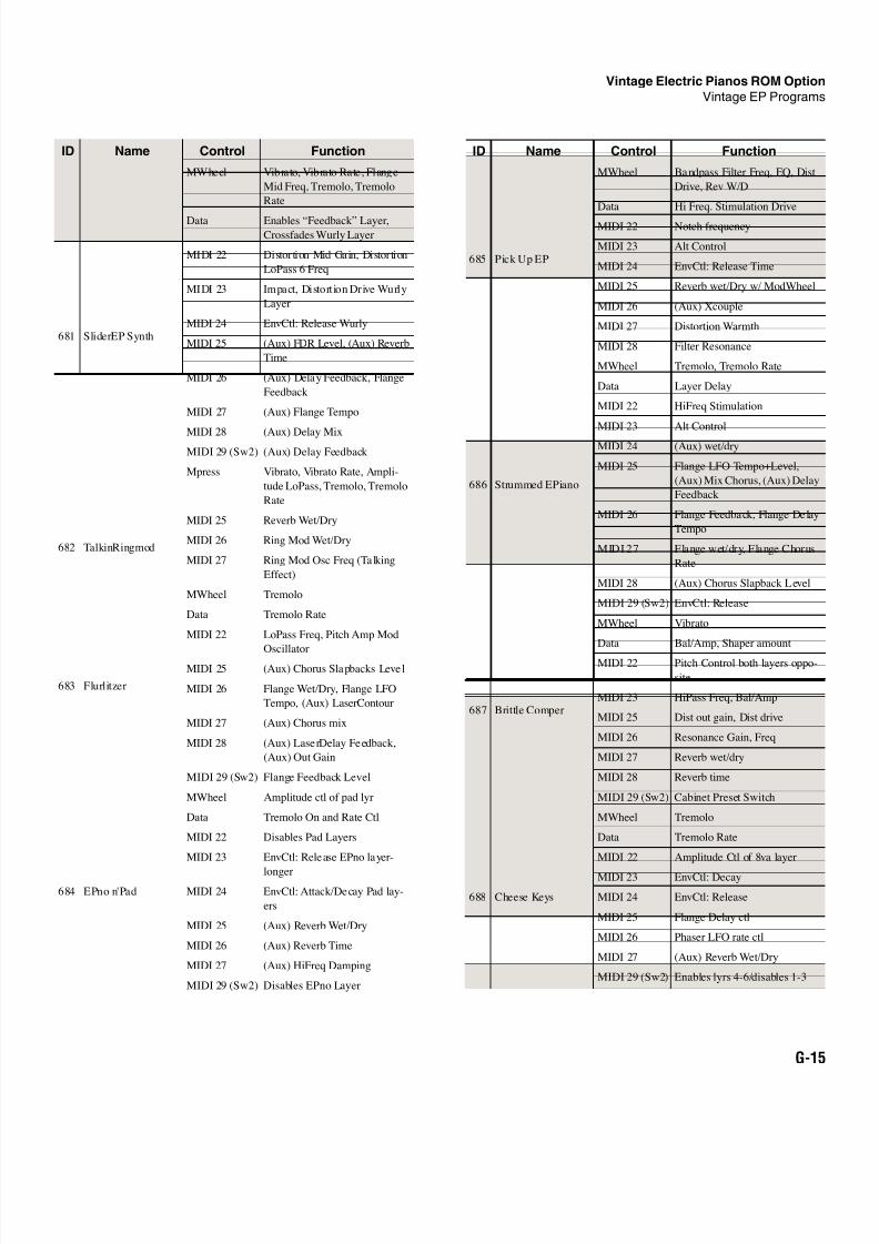
8/21/2019 MR_K2661
http://slidepdf.com/reader/full/mrk2661 473/499
Vintage Electric Pianos ROM Option
Vintage EP Programs
G-15
681 SliderEP Synth
MWheel Vibrato, Vibrato Rate, Flange
Mid Freq, Tremolo, Tremolo
Rate
Data Enables “Feedback” Layer,Crossfades Wurly Layer
MIDI 22 Distortion Mid Gain, Distortion
LoPass 6 Freq
MIDI 23 Impact, Distort ion Drive Wurly
Layer
MIDI 24 EnvCtl: Release Wurly
MIDI 25 (Aux) FDR Level, (Aux) Reverb
Time
MIDI 26 (Aux) Delay Feedback, Flange
Feedback
MIDI 27 (Aux) Flange Tempo
MIDI 28 (Aux) Delay MixMIDI 29 (Sw2) (Aux) Delay Feedback
Mpress Vibrato, Vibrato Rate, Ampli-
tude LoPass, Tremolo, Tremolo
Rate
682 TalkinRingmod
MIDI 25 Reverb Wet/Dry
MIDI 26 Ring Mod Wet/Dry
MIDI 27 Ring Mod Osc Freq (Talking
Effect)
683 Flurlitzer
MWheel Tremolo
Data Tremolo Rate
MIDI 22 LoPass Freq, Pitch Amp Mod
OscillatorMIDI 25 (Aux) Chorus Slapbacks Level
MIDI 26 Flange Wet/Dry, Flange LFO
Tempo, (Aux) LaserContour
MIDI 27 (Aux) Chorus mix
MIDI 28 (Aux) LaserDelay Feedback,
(Aux) Out Gain
MIDI 29 (Sw2) Flange Feedback Level
684 EPno n'Pad
MWheel Amplitude ctl of pad lyr
Data Tremolo On and Rate Ctl
MIDI 22 Disables Pad Layers
MIDI 23 EnvCtl: Release EPno layer-
longer
MIDI 24 EnvCtl: Attack/Decay Pad lay-
ers
MIDI 25 (Aux) Reverb Wet/Dry
MIDI 26 (Aux) Reverb Time
MIDI 27 (Aux) HiFreq Damping
MIDI 29 (Sw2) Disables EPno Layer
ID Name Control Function
685 Pick Up EP
MWheel Bandpass Filter Freq, EQ, Dist
Drive, Rev W/D
Data Hi Freq. Stimulation Drive
MIDI 22 Notch frequency
MIDI 23 Alt Control
MIDI 24 EnvCtl: Release Time
MIDI 25 Reverb wet/Dry w/ ModWheel
MIDI 26 (Aux) Xcouple
MIDI 27 Distortion Warmth
MIDI 28 Filter Resonance
686 Strummed EPiano
MWheel Tremolo, Tremolo Rate
Data Layer Delay
MIDI 22 HiFreq Stimulation
MIDI 23 Alt Control
MIDI 24 (Aux) wet/dry
MIDI 25 Flange LFO Tempo+Level,
(Aux) Mix Chorus, (Aux) Delay
Feedback
MIDI 26 Flange Feedback, Flange Delay
Tempo
MIDI 27 Flange wet/dry, Flange Chorus
Rate
MIDI 28 (Aux) Chorus Slapback Level
MIDI 29 (Sw2) EnvCtl: Release
687 Brittle Comper
MWheel Vibrato
Data Bal/Amp, Shaper amount
MIDI 22 Pitch Control both layers oppo-
site
MIDI 23 HiPass Freq, Bal/Amp
MIDI 25 Dist out gain, Dist drive
MIDI 26 Resonance Gain, Freq
MIDI 27 Reverb wet/dry
MIDI 28 Reverb time
MIDI 29 (Sw2) Cabinet Preset Switch
688 Cheese Keys
MWheel Tremolo
Data Tremolo Rate
MIDI 22 Amplitude Ctl of 8va layer
MIDI 23 EnvCtl: Decay
MIDI 24 EnvCtl: Release
MIDI 25 Flange Delay ctl
MIDI 26 Phaser LFO rate ctl
MIDI 27 (Aux) Reverb Wet/Dry
MIDI 29 (Sw2) Enables lyrs 4-6/disables 1-3
ID Name Control Function
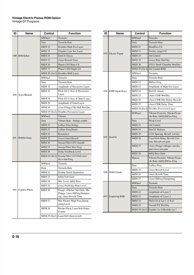
8/21/2019 MR_K2661
http://slidepdf.com/reader/full/mrk2661 474/499
G-16
Vintage Electric Pianos ROM Option
Vintage EP Programs
689 RM-Either
MWheel Tremolo
Data Tremolo Rate
MIDI 22 Disables High 8va LayerMIDI 23 Disables Low 8va Layer
MIDI 24 EnvCtl: Decay
MIDI 25 (Aux) Reverb Time
MIDI 26 Phaser LFO Rate Ctl
MIDI 27 Phaser LFO Depth Ctl
MIDI 29 (Sw2) Disables RMI Layer
690 Xylo-Rhoadz
MWheel Tremolo
Data Tremolo Rate
MIDI 22 Amplitude of Percussive Layer
MIDI 23 Pitch Ctl (1 8va) of Percussive
Layer
MIDI 24 Pitch Ctl (1 8va) of Tonal Layer
MIDI 25 Amplitude of Tonal Layer
MIDI 26 (Aux) Flange-Dly Hall Wet/Dry
MIDI 29 (Sw2) Disables Percussive Layer
691 Bubble Snap
MWheel Vibrato
Data Vibrato Rate - Strings enable
MIDI 22 LoPass Freq Strings
MIDI 23 LoPass Freq Pianet
MIDI 24 Resonance
MIDI 25 (Aux) Gated Reverb
MIDI 26 Sweep Filter LFO smooth
MIDI 27 Sweep Filter Max Freq
MIDI 28 Delay Feedback Level
MIDI 29 (Sw2) Sweep Filter LFO Halt+wet/
dry+ min Freq
692 Cypress Pluck
MWheel Tremolo
Data Tremolo Rate
MIDI 22 Double Notch Separation
MIDI 23 InEQ Treb Gain
MIDI 24 Mix Level, InEQ Bass
MIDI 25 (Aux) PreDelay Plate Level
MIDI 26 Flange->Pitcher Out Gain, Mix
Flange, (Aux) HiFreq Dampen-ing, (Aux) Reverb Time
MIDI 27 Mix Pitcher, High Freq Damp-
ening Level
MIDI 28 Pitcher Pitch, LaserVerb Delay
Coarse
MIDI 29 (Sw2) LaserVerb (bus) switch
ID Name Control Function
693 Electro Fugue
MWheel Tremolo
Data Tremolo Rate
MIDI 22 BandPass CtlMIDI 23 Timbre (amp) Ctl
MIDI 24 Alt Control
MIDI 25 (Aux) Plate Wet/Dry
MIDI 26 (FX1) Small Chamber Wet/Dry
MIDI 29 (Sw2) Alt Control RMI
694 RMI Organ Keys
MWheel Tremolo
Data Tremolo Rate
MIDI 22 HiPass Freq
MIDI 23 Amplitude of High 8va Layer
MIDI 24 EnvCtl: Attack
MIDI 25 (Aux) CDR Wet/DryMIDI 26 (Aux) CDR Mix Delay/ Reverb
MIDI 27 (Aux) CDR Delay Time
MIDI 29 (Sw2) Disables Percussive Layer
695 Hurtful
MWheel Vibrato/Tremolo, Vibrato/Trem-
olo Rate, InEQ HiPass Freq
Data Wrap Level
MIDI 23 Alt Control
MIDI 24 EnvCtl: Release
MIDI 25 LVrb Spacing, Reverb wet/dry
MIDI 26 LaserVerb Delay, Reverb Con-
tour, Reverb out gain
MIDI 27 (Aux) Flange->Shaper wet/dry
and (Aux) out gain
MIDI 28 InEQ Bass Gain
Mpress Vibrato/Tremolo, Vibrato/Trem-
olo Rate, InEQ HiPass Freq
696 Multi Grand
Data LoPass Freq
MIDI 25 (Aux) Reverb Level
MIDI 26 (Aux) Reverb Time
MIDI 27 (Aux) HiFreq Dampening
697 Exploring RMI
MWheel Tremolo
Data Tremolo Rate
MIDI 22 Amplitude of Layer 2MIDI 23 Amplitude of Layer 3
MIDI 24 Pitch Ctl of Lyr 1 (1 8va)
MIDI 25 Overall FX Wet/Dry
MIDI 29 (Sw2) Enables lyr 4/Disables lyr 1
ID Name Control Function
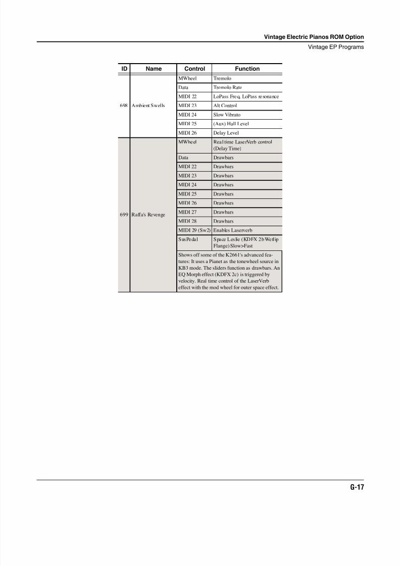
8/21/2019 MR_K2661
http://slidepdf.com/reader/full/mrk2661 475/499
Vintage Electric Pianos ROM Option
Vintage EP Programs
G-17
698 Ambient Swells
MWheel Tremolo
Data Tremolo Rate
MIDI 22 LoPass Freq, LoPass resonanceMIDI 23 Alt Control
MIDI 24 Slow Vibrato
MIDI 25 (Aux) Hall Level
MIDI 26 Delay Level
699 Raffa's Revenge
MWheel Real time LaserVerb control
(Delay Time)
Data Drawbars
MIDI 22 Drawbars
MIDI 23 Drawbars
MIDI 24 Drawbars
MIDI 25 Drawbars
MIDI 26 Drawbars
MIDI 27 Drawbars
MIDI 28 Drawbars
MIDI 29 (Sw2) Enables Laserverb
SusPedal Space Leslie (KDFX 2b Wetlip
Flange) Slow>Fast
Shows off some of the K2661's advanced fea-
tures: It uses a Pianet as the tonewheel source in
KB3 mode. The sliders function as drawbars. An
EQ Morph effect (KDFX 2c) is triggered by
velocity. Real time control of the LaserVerb
effect with the mod wheel for outer space effect.
ID Name Control Function
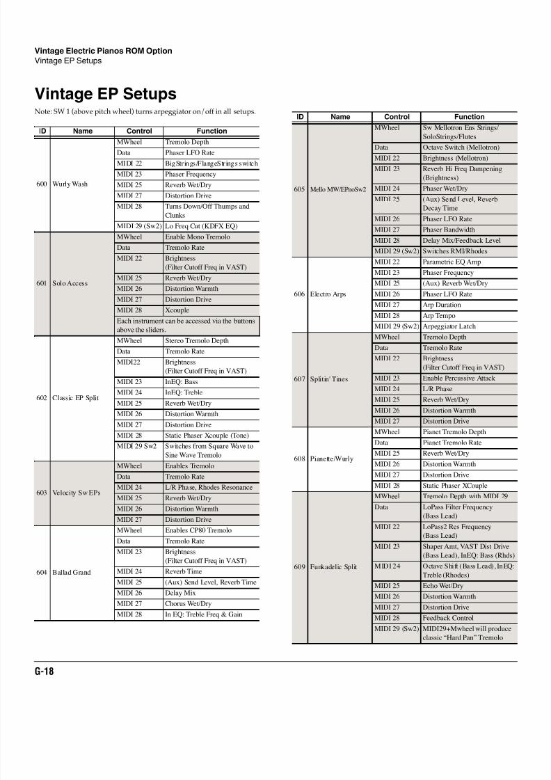
8/21/2019 MR_K2661
http://slidepdf.com/reader/full/mrk2661 476/499
G-18
Vintage Electric Pianos ROM Option
Vintage EP Setups
Vintage EP SetupsNote: SW 1 (above pitch wheel) turns arpeggiator on/off in all setups.
ID Name Control Function
600 Wurly Wash
MWheel Tremolo Depth
Data Phaser LFO Rate
MIDI 22 BigStrings/FlangeStrings switch
MIDI 23 Phaser Frequency
MIDI 25 Reverb Wet/Dry
MIDI 27 Distortion Drive
MIDI 28 Turns Down/Off Thumps and
Clunks
MIDI 29 (Sw2) Lo Freq Cut (KDFX EQ)
601 Solo Access
MWheel Enable Mono Tremolo
Data Tremolo Rate
MIDI 22 Brightness
(Filter Cutoff Freq in VAST)
MIDI 25 Reverb Wet/Dry
MIDI 26 Distortion Warmth
MIDI 27 Distortion Drive
MIDI 28 Xcouple
Each instrument can be accessed via the buttons
above the sliders.
602 Classic EP Split
MWheel Stereo Tremolo Depth
Data Tremolo Rate
MIDI22 Brightness
(Filter Cutoff Freq in VAST)
MIDI 23 InEQ: Bass
MIDI 24 InEQ: Treble
MIDI 25 Reverb Wet/Dry
MIDI 26 Distortion Warmth
MIDI 27 Distortion Drive
MIDI 28 Static Phaser Xcouple (Tone)
MIDI 29 Sw2 Switches from Square Wave to
Sine Wave Tremolo
603 Velocity Sw EPs
MWheel Enables Tremolo
Data Tremolo Rate
MIDI 24 L/R Phase, Rhodes Resonance
MIDI 25 Reverb Wet/Dry
MIDI 26 Distortion Warmth
MIDI 27 Distortion Drive
604 Ballad Grand
MWheel Enables CP80 Tremolo
Data Tremolo Rate
MIDI 23 Brightness
(Filter Cutoff Freq in VAST)
MIDI 24 Reverb Time
MIDI 25 (Aux) Send Level, Reverb Time
MIDI 26 Delay Mix
MIDI 27 Chorus Wet/Dry
MIDI 28 In EQ: Treble Freq & Gain
605 Mello MW/EPnoSw2
MWheel Sw Mellotron Ens Strings/
SoloStrings/FlutesData Octave Switch (Mellotron)
MIDI 22 Brightness (Mellotron)
MIDI 23 Reverb Hi Freq Dampening
(Brightness)
MIDI 24 Phaser Wet/Dry
MIDI 25 (Aux) Send Level, Reverb
Decay Time
MIDI 26 Phaser LFO Rate
MIDI 27 Phaser Bandwidth
MIDI 28 Delay Mix/Feedback Level
MIDI 29 (Sw2) Switches RMI/Rhodes
606 Electro Arps
MIDI 22 Parametric EQ Amp
MIDI 23 Phaser FrequencyMIDI 25 (Aux) Reverb Wet/Dry
MIDI 26 Phaser LFO Rate
MIDI 27 Arp Duration
MIDI 28 Arp Tempo
MIDI 29 (Sw2) Arpeggiator Latch
607 Splitin' Tines
MWheel Tremolo Depth
Data Tremolo Rate
MIDI 22 Brightness
(Filter Cutoff Freq in VAST)
MIDI 23 Enable Percussive Attack
MIDI 24 L/R Phase
MIDI 25 Reverb Wet/Dry
MIDI 26 Distortion Warmth
MIDI 27 Distortion Drive
608 Pianette/Wurly
MWheel Pianet Tremolo Depth
Data Pianet Tremolo Rate
MIDI 25 Reverb Wet/Dry
MIDI 26 Distortion Warmth
MIDI 27 Distortion Drive
MIDI 28 Static Phaser XCouple
609 Funkadelic Split
MWheel Tremolo Depth with MIDI 29
Data LoPass Filter Frequency
(Bass Lead)
MIDI 22 LoPass2 Res Frequency
(Bass Lead)
MIDI 23 Shaper Amt, VAST Dist Drive(Bass Lead), InEQ: Bass (Rhds)
MIDI 24 Octave Shift (Bass Lead), InEQ:
Treble (Rhodes)
MIDI 25 Echo Wet/Dry
MIDI 26 Distortion Warmth
MIDI 27 Distortion Drive
MIDI 28 Feedback Control
MIDI 29 (Sw2) MIDI29+Mwheel will produce
classic “Hard Pan” Tremolo
ID Name Control Function
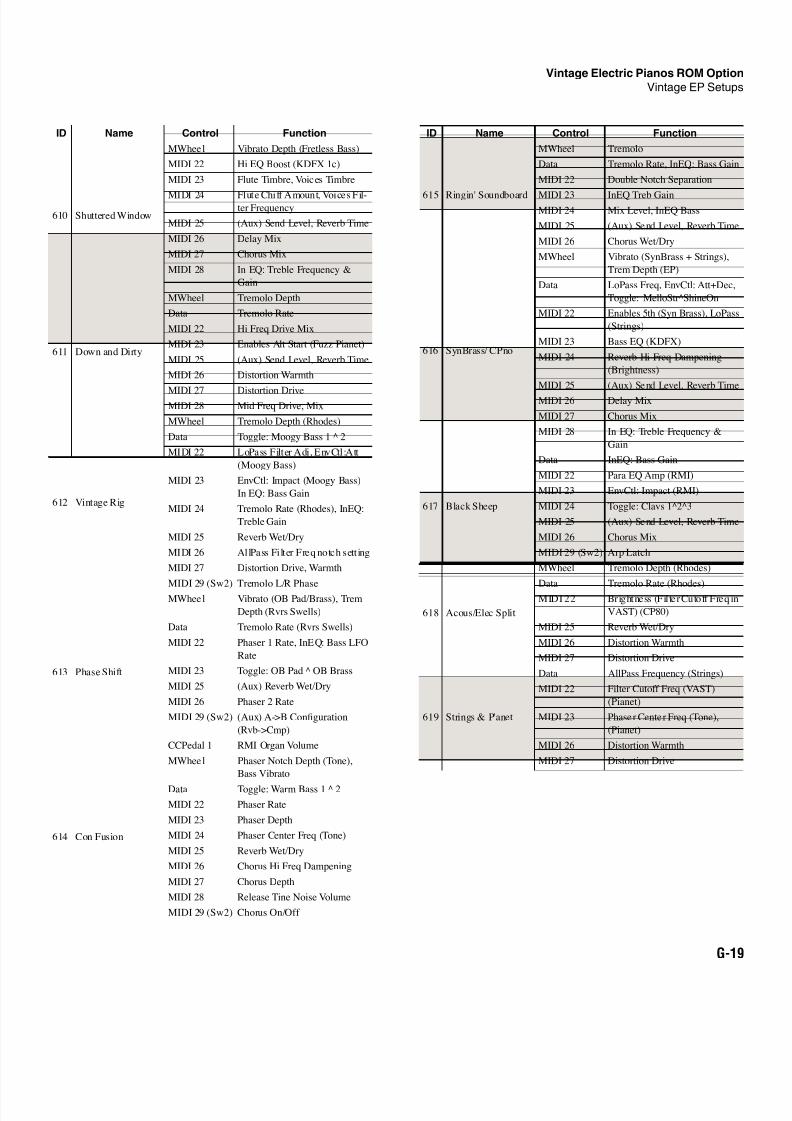
8/21/2019 MR_K2661
http://slidepdf.com/reader/full/mrk2661 477/499
Vintage Electric Pianos ROM Option
Vintage EP Setups
G-19
610 Shuttered Window
MWheel Vibrato Depth (Fretless Bass)
MIDI 22 Hi EQ Boost (KDFX 1c)
MIDI 23 Flute Timbre, Voices Timbre
MIDI 24 Flute Chiff Amount, Voices Fil-ter Frequency
MIDI 25 (Aux) Send Level, Reverb Time
MIDI 26 Delay Mix
MIDI 27 Chorus Mix
MIDI 28 In EQ: Treble Frequency &
Gain
611 Down and Dirty
MWheel Tremolo Depth
Data Tremolo Rate
MIDI 22 Hi Freq Drive Mix
MIDI 23 Enables Alt Start (Fuzz Pianet)
MIDI 25 (Aux) Send Level, Reverb Time
MIDI 26 Distortion Warmth
MIDI 27 Distortion DriveMIDI 28 Mid Freq Drive, Mix
612 Vintage Rig
MWheel Tremolo Depth (Rhodes)
Data Toggle: Moogy Bass 1 2
MIDI 22 LoPass Filter Adj, EnvCtl:Att
(Moogy Bass)
MIDI 23 EnvCtl: Impact (Moogy Bass)
In EQ: Bass Gain
MIDI 24 Tremolo Rate (Rhodes), InEQ:
Treble Gain
MIDI 25 Reverb Wet/Dry
MIDI 26 AllPass Filter Freq notch sett ing
MIDI 27 Distortion Drive, Warmth
MIDI 29 (Sw2) Tremolo L/R Phase
613 Phase Shift
MWheel Vibrato (OB Pad/Brass), Trem
Depth (Rvrs Swells)
Data Tremolo Rate (Rvrs Swells)
MIDI 22 Phaser 1 Rate, InEQ: Bass LFO
Rate
MIDI 23 Toggle: OB Pad OB Brass
MIDI 25 (Aux) Reverb Wet/Dry
MIDI 26 Phaser 2 Rate
MIDI 29 (Sw2) (Aux) A->B Configuration
(Rvb->Cmp)
CCPedal 1 RMI Organ Volume
614 Con Fusion
MWheel Phaser Notch Depth (Tone),
Bass Vibrato
Data Toggle: Warm Bass 1 2
MIDI 22 Phaser Rate
MIDI 23 Phaser Depth
MIDI 24 Phaser Center Freq (Tone)
MIDI 25 Reverb Wet/Dry
MIDI 26 Chorus Hi Freq Dampening
MIDI 27 Chorus Depth
MIDI 28 Release Tine Noise Volume
MIDI 29 (Sw2) Chorus On/Off
ID Name Control Function
615 Ringin' Soundboard
MWheel Tremolo
Data Tremolo Rate, InEQ: Bass Gain
MIDI 22 Double Notch Separation
MIDI 23 InEQ Treb GainMIDI 24 Mix Level, InEQ Bass
MIDI 25 (Aux) Send Level, Reverb Time
MIDI 26 Chorus Wet/Dry
616 SynBrass/ CPno
MWheel Vibrato (SynBrass + Strings),
Trem Depth (EP)
Data LoPass Freq, EnvCtl: Att+Dec,
Toggle: MelloStr^ShineOn
MIDI 22 Enables 5th (Syn Brass), LoPass
(Strings)
MIDI 23 Bass EQ (KDFX)
MIDI 24 Reverb Hi Freq Dampening
(Brightness)
MIDI 25 (Aux) Send Level, Reverb Time
MIDI 26 Delay Mix
MIDI 27 Chorus Mix
MIDI 28 In EQ: Treble Frequency &
Gain
617 Black Sheep
Data InEQ: Bass Gain
MIDI 22 Para EQ Amp (RMI)
MIDI 23 EnvCtl: Impact (RMI)
MIDI 24 Toggle: Clavs 1^2^3
MIDI 25 (Aux) Send Level, Reverb Time
MIDI 26 Chorus Mix
MIDI 29 (Sw2) Arp Latch
618 Acous/Elec Split
MWheel Tremolo Depth (Rhodes)
Data Tremolo Rate (Rhodes)
MIDI 22 Brightness (Fil ter Cutoff Freq in
VAST) (CP80)
MIDI 25 Reverb Wet/Dry
MIDI 26 Distortion Warmth
MIDI 27 Distortion Drive
619 Strings & P'anet
Data AllPass Frequency (Strings)
MIDI 22 Filter Cutoff Freq (VAST)
(Pianet)
MIDI 23 Phaser Center Freq (Tone),
(Pianet)
MIDI 26 Distortion Warmth
MIDI 27 Distortion Drive
ID Name Control Function
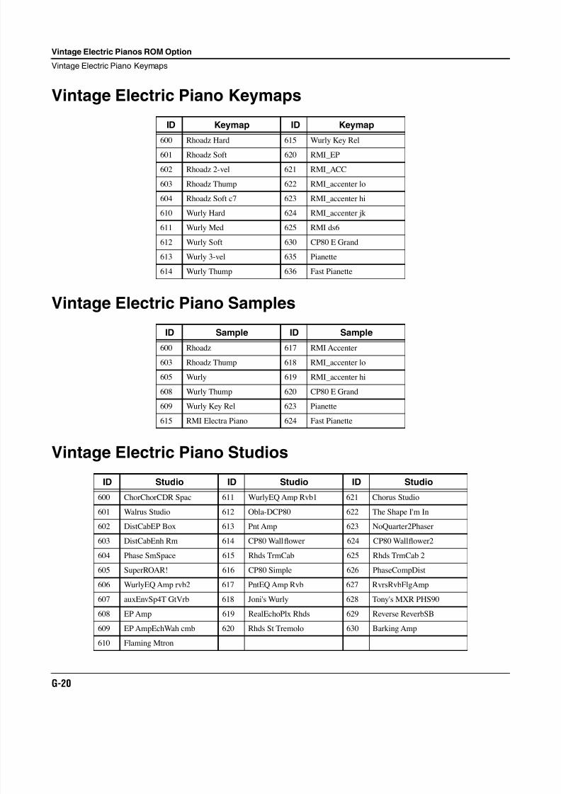
8/21/2019 MR_K2661
http://slidepdf.com/reader/full/mrk2661 478/499
G-20
Vintage Electric Pianos ROM Option
Vintage Electric Piano Keymaps
Vintage Electric Piano Keymaps
Vintage Electric Piano Samples
Vintage Electric Piano Studios
ID Keymap ID Keymap
600 Rhoadz Hard 615 Wurly Key Rel
601 Rhoadz Soft 620 RMI_EP
602 Rhoadz 2-vel 621 RMI_ACC
603 Rhoadz Thump 622 RMI_accenter lo
604 Rhoadz Soft c7 623 RMI_accenter hi
610 Wurly Hard 624 RMI_accenter jk
611 Wurly Med 625 RMI ds6
612 Wurly Soft 630 CP80 E Grand
613 Wurly 3-vel 635 Pianette
614 Wurly Thump 636 Fast Pianette
ID Sample ID Sample
600 Rhoadz 617 RMI Accenter
603 Rhoadz Thump 618 RMI_accenter lo
605 Wurly 619 RMI_accenter hi
608 Wurly Thump 620 CP80 E Grand
609 Wurly Key Rel 623 Pianette
615 RMI Electra Piano 624 Fast Pianette
ID Studio ID Studio ID Studio
600 ChorChorCDR Spac 611 WurlyEQ Amp Rvb1 621 Chorus Studio
601 Walrus Studio 612 Obla-DCP80 622 The Shape I'm In
602 DistCabEP Box 613 Pnt Amp 623 NoQuarter2Phaser
603 DistCabEnh Rm 614 CP80 Wallflower 624 CP80 Wallflower2
604 Phase SmSpace 615 Rhds TrmCab 625 Rhds TrmCab 2
605 SuperROAR! 616 CP80 Simple 626 PhaseCompDist
606 WurlyEQ Amp rvb2 617 PntEQ Amp Rvb 627 RvrsRvbFlgAmp
607 auxEnvSp4T GtVrb 618 Joni's Wurly 628 Tony's MXR PHS90
608 EP Amp 619 RealEchoPlx Rhds 629 Reverse ReverbSB
609 EP AmpEchWah cmb 620 Rhds St Tremolo 630 Barking Amp
610 Flaming Mtron
8/21/2019 MR_K2661
http://slidepdf.com/reader/full/mrk2661 479/499
Appendix H
General MIDIGeneral MIDI (GM) is an addition to the original MIDI specification that assigns sounds tospecific channel numbers, program numbers, and note values. The K2661’s GM Mode feature(described in Chapter 11 of the Musician’s Guide) sets up your instrument for GM in a single step.Using General MIDI, you can share song files between different devices with reasonablyconsistent performance.
Many GM song files are commercially available, and they’ll sound great on your K2661.
Inside GM ModeHere’s what happens when you enable GM Mode from the Master Page:
• On all channels except channel 10 (which GM uses for drums), you will see only the 128 GMprograms. On MIDI channel 10, you will see the eight drum kits.
• The K2661 will modify the following entries in the master table:
• FX mode (GM uses Master mode)• FX channel (GM uses None)• FX studio (GM uses the studio selected in GM Studio set on the Master: GM page)• Receive velocity map (GM uses the GM Receive Velocity Map)• progChgType (GM uses 0-127 mode)
Old settings will be remembered, however, so that when you turn GM Mode off the K2661will restore your previous settings.
• Volume and expression controllers are mapped to a special GM curve, as in “GS” synths.(GS is a superset of General MIDI that is used by the Roland Sound Canvas and otherproducts.)
• GM drum kits are mapped across program number space as in the “GS” synths, and haveexclusive zones included with them.
• Program changes sent to the K2661 when it is in GM Mode will only select programs fromthe GM program set.
Setups, Songs, and QA Banks created outside of GM Mode will not point to the correct programs withinGM Mode (although you may find the results “interesting”). Similarly, Setups, Songs, and QA Banks
created within GM Mode will not point to the correct programs when you leave GM Mode. For thisreason, when you create Setups, Songs, or QA Banks within GM Mode you may want to append theletters “GM” to the object’s name and/or store the objects only in certain banks.
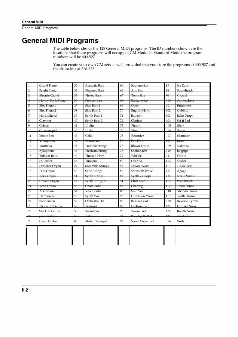
8/21/2019 MR_K2661
http://slidepdf.com/reader/full/mrk2661 480/499
H-2
General MIDI
General MIDI Programs
General MIDI ProgramsThe table below shows the 128 General MIDI programs. The ID numbers shown are thelocations that these programs will occupy in GM Mode. In Standard Mode the program
numbers will be 400-527.You can create your own GM sets as well, provided that you store the programs at 400-527 andthe drum kits at 528-535.
1 Grand Piano 33 Acoustic Bass 65 Soprano Sax 97 Ice Rain
2 Bright Piano 34 Fingered Bass 66 Alto Sax 98 Soundtrack
3 Electric Grand 35 Picked Bass 67 Tenor Sax 99 Crystal
4 Honky-Tonk Piano 36 Fretless Bass 68 Baritone Sax 100 Atmosphere
5 Elec Piano 1 37 Slap Bass 1 69 Oboe 101 Brightness
6 Elec Piano 2 38 Slap Bass 2 70 English Horn 102 Goblins
7 Harpsichord 39 Synth Bass 1 71 Bassoon 103 Echo Drops
8 Clavinet 40 Synth Bass 2 72 Clarinet 104 Sci-fi Pad
9 Celeste 41 Violin 73 Piccolo 105 Sitar
10 Glockenspiel 42 Viola 74 Flute 106 Banjo
11 Music Box 43 Cello 75 Recorder 107 Shamisen
12 Vibraphone 44 Contrabass 76 Pan Flute 108 Koto
13 Marimba 45 Tremolo Strings 77 Blown Bottle 109 Kalimba
14 Xylophone 46 Pizzicato String 78 Shakuhachi 110 Bagpipe
15 Tubular Bells 47 Plucked Harp 79 Whistle 111 Fiddle
16 Dulcimer 48 Timpani 80 Ocarina 112 Shanai
17 Drawbar Organ 49 Ensemble Strings 81 Square Wave 113 Tinkle Bell
18 Perc Organ 50 Slow Strings 82 Sawtooth Wave 114 Agogo
19 Rock Organ 51 Synth Strings 1 83 Synth Calliope 115 Steel Drums20 Church Organ 52 Synth Strings 2 84 Chiff Lead 116 Woodblock
21 Reed Organ 53 Choir Oohs 85 Charang 117 Taiko Drum
22 Accordion 54 Voice Oohs 86 Solo Vox 118 Melodic Toms
23 Harmonica 55 Synth Vox 87 Fifths Saw Wave 119 Synth Drums
24 Bandoneon 56 Orchestra Hit 88 Bass & Lead 120 Reverse Cymbal
25 Nylon Str Guitar 57 Trumpet 89 Fantasia Pad 121 Gtr Fret Noise
26 Steel Str Guitar 58 Trombone 90 Warm Pad 122 Breath Noise
27 Jazz Guitar 59 Tuba 91 Poly Synth Pad 123 Seashore
28 Clean Guitar 60 Muted Trumpet 92 Space Voice Pad 124 Birds
29 Muted Guitar 61 French Horn 93 Bowed Glass Pad 125 Telephone
30 Overdrive Guitar 62 Brass Section 94 Metallic Pad 126 Helicopter
31 Distorted Guitar 63 Synth Brass 1 95 Halo Pad 127 Applause32 Guitar Harmonics 64 Synth Brass 2 96 Sweep Pad 128 Gun Shot
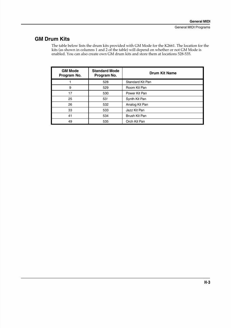
8/21/2019 MR_K2661
http://slidepdf.com/reader/full/mrk2661 481/499
General MIDI
General MIDI Programs
H-3
GM Drum KitsThe table below lists the drum kits provided with GM Mode for the K2661. The location for thekits (as shown in columns 1 and 2 of the table) will depend on whether or not GM Mode isenabled. You can also create own GM drum kits and store them at locations 528-535.
GM ModeProgram No.
Standard ModeProgram No.
Drum Kit Name
1 528 Standard Kit Pan
9 529 Room Kit Pan
17 530 Power Kit Pan
25 531 Synth Kit Pan
26 532 Analog Kit Pan
33 533 Jazz Kit Pan
41 534 Brush Kit Pan
49 535 Orch Kit Pan
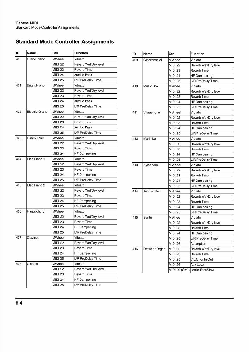
8/21/2019 MR_K2661
http://slidepdf.com/reader/full/mrk2661 482/499
H-4
General MIDI
Standard Mode Controller Assignments
Standard Mode Controller Assignments
ID Name Ctrl Function
400 Grand Piano MWheel Vibrato
MIDI 22 Reverb Wet/Dry level
MIDI 23 Reverb Time
MIDI 24 Aux Lo Pass
MIDI 25 L/R PreDelay Time
401 Bright Piano MWheel Vibrato
MIDI 22 Reverb Wet/Dry level
MIDI 23 Reverb Time
MIDI 24 Aux Lo Pass
MIDI 25 L/R PreDelay Time
402 Electric Grand MWheel Vibrato
MIDI 22 Reverb Wet/Dry level
MIDI 23 Reverb TimeMIDI 24 Aux Lo Pass
MIDI 25 L/R PreDelay Time
403 Honky Tonk MWheel Vibrato
MIDI 22 Reverb Wet/Dry level
MIDI 23 Reverb Time
MIDI 24 HF Dampening
404 Elec Piano 1 MWheel Vibrato
MIDI 22 Reverb Wet/Dry level
MIDI 23 Reverb Time
MIDI 24 HF Dampening
MIDI 25 L/R PreDelay Time
405 Elec Piano 2 MWheel Vibrato
MIDI 22 Reverb Wet/Dry level
MIDI 23 Reverb Time
MIDI 24 HF Dampening
MIDI 25 L/R PreDelay Time
406 Harpsichord MWheel Vibrato
MIDI 22 Reverb Wet/Dry level
MIDI 23 Reverb Time
MIDI 24 HF Dampening
MIDI 25 L/R PreDelay Time
407 Clavinet MWheel Vibrato
MIDI 22 Reverb Wet/Dry level
MIDI 23 Reverb Time
MIDI 24 HF Dampening
MIDI 25 L/R PreDelay Time
408 Celeste MWheel Vibrato
MIDI 22 Reverb Wet/Dry level
MIDI 23 Reverb Time
MIDI 24 HF Dampening
MIDI 25 L/R PreDelay Time
409 Glockenspiel MWheel VibratoMIDI 22 Reverb Wet/Dry level
MIDI 23 Reverb Time
MIDI 24 HF Dampening
MIDI 25 L/R PreDelay Time
410 Music Box MWheel Vibrato
MIDI 22 Reverb Wet/Dry level
MIDI 23 Reverb Time
MIDI 24 HF Dampening
MIDI 25 L/R PreDelay Time
411 Vibraphone MWheel Vibrato
MIDI 22 Reverb Wet/Dry level
MIDI 23 Reverb TimeMIDI 24 HF Dampening
MIDI 25 L/R PreDelay Time
412 Marimba MWheel Vibrato
MIDI 22 Reverb Wet/Dry level
MIDI 23 Reverb Time
MIDI 24 HF Dampening
MIDI 25 L/R PreDelay Time
413 Xylophone MWheel Vibrato
MIDI 22 Reverb Wet/Dry level
MIDI 23 Reverb Time
MIDI 24 HF Dampening
MIDI 25 L/R PreDelay Time
414 Tubular Bell MWheel Vibrato
MIDI 22 Reverb Wet/Dry level
MIDI 23 Reverb Time
MIDI 24 HF Dampening
MIDI 25 L/R PreDelay Time
415 Santur MWheel Vibrato
MIDI 22 Reverb Wet/Dry level
MIDI 23 Reverb Time
MIDI 24 HF Dampening
MIDI 25 L/R PreDelay Time
MIDI 26 Absorption
416 Drawbar Organ MIDI 22 Reverb Wet/Dry level
MIDI 23 Reverb Time
MIDI 25 Vib/Chor In/Out
MIDI 26 Aux Level
MIDI 29 (Sw2) Leslie Fast/Slow
ID Name Ctrl Function
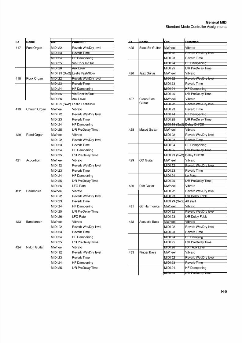
8/21/2019 MR_K2661
http://slidepdf.com/reader/full/mrk2661 483/499
General MID
Standard Mode Controller Assignments
H-5
417 Perc Organ MIDI 22 Reverb Wet/Dry level
MIDI 23 Reverb Time
MIDI 24 HF Dampening
MIDI 25 Vib/Chor In/Out
MIDI 26 Aux Level
MIDI 29 (Sw2) Leslie Fast/Slow
418 Rock Organ MIDI 22 Reverb Wet/Dry level
MIDI 23 Reverb Time
MIDI 24 HF Dampening
MIDI 25 Vib/Chor In/Out
MIDI 26 Aux Level
MIDI 29 (Sw2) Leslie Fast/Slow
419 Church Organ MWheel Vibrato
MIDI 22 Reverb Wet/Dry level
MIDI 23 Reverb TimeMIDI 24 HF Dampening
MIDI 25 L/R PreDelay Time
420 Reed Organ MWheel Vibrato
MIDI 22 Reverb Wet/Dry level
MIDI 23 Reverb Time
MIDI 24 HF Dampening
MIDI 25 L/R PreDelay Time
421 Accordion MWheel Vibrato
MIDI 22 Reverb Wet/Dry level
MIDI 23 Reverb Time
MIDI 24 HF Dampening
MIDI 25 L/R PreDelay Time
MIDI 26 LFO Rate
422 Harmonica MWheel Vibrato
MIDI 22 Reverb Wet/Dry level
MIDI 23 Reverb Time
MIDI 24 HF Dampening
MIDI 25 L/R PreDelay Time
MIDI 26 LFO Rate
423 Bandoneon MWheel Vibrato
MIDI 22 Reverb Wet/Dry level
MIDI 23 Reverb Time
MIDI 24 HF Dampening
MIDI 25 L/R PreDelay Time
424 Nylon Guitar MWheel Vibrato
MIDI 22 Reverb Wet/Dry level
MIDI 23 Reverb Time
MIDI 24 HF Dampening
MIDI 25 L/R PreDelay Time
ID Name Ctrl Function
425 Steel Str Guitar MWheel Vibrato
MIDI 22 Reverb Wet/Dry level
MIDI 23 Reverb Time
MIDI 24 HF Dampening
MIDI 25 L/R PreDelay Time
426 Jazz Guitar MWheel Vibrato
MIDI 22 Reverb Wet/Dry level
MIDI 23 Reverb Time
MIDI 24 HF Dampening
MIDI 25 L/R PreDelay Time
427 Clean Elec
Guitar
MWheel Vibrato
MIDI 22 Reverb Wet/Dry level
MIDI 23 Reverb Time
MIDI 24 HF Dampening
MIDI 25 L/R PreDelay TimeMIDI 29 (Sw2) Delay ON/Off
428 Muted Guitar MWheel Vibrato
MIDI 22 Reverb Wet/Dry level
MIDI 23 Reverb Time
MIDI 24 HF Dampening
MIDI 25 L/R PreDelay Time
MIDI 29 (Sw2) Delay ON/Off
429 OD Guitar MWheel Vibrato
MIDI 22 Reverb Wet/Dry level
MIDI 23 Reverb Time
MIDI 24 Lo Pass
MIDI 25 L/R PreDelay Time
430 Dist Guitar MWheel Vibrato
MIDI 22 Reverb Wet/Dry level
MIDI 23 L/R Delay Fdbk
MIDI 29 (Sw2) Alt start
431 Gtr Harmonics MWheel Vibrato
MIDI 22 Reverb Wet/Dry level
MIDI 23 L/R Delay Fdbk
432 Acoustic Bass MWheel Vibrato
MIDI 22 Reverb Wet/Dry level
MIDI 23 Reverb Time
MIDI 24 HF Damping
MIDI 25 L/R PreDelay Time
MIDI 26 FX1 Aux Level
433 Finger Bass MWheel Vibrato
MIDI 22 Reverb Wet/Dry level
MIDI 23 Reverb Time
MIDI 24 HF Dampening
MIDI 25 L/R PreDelay Time
ID Name Ctrl Function
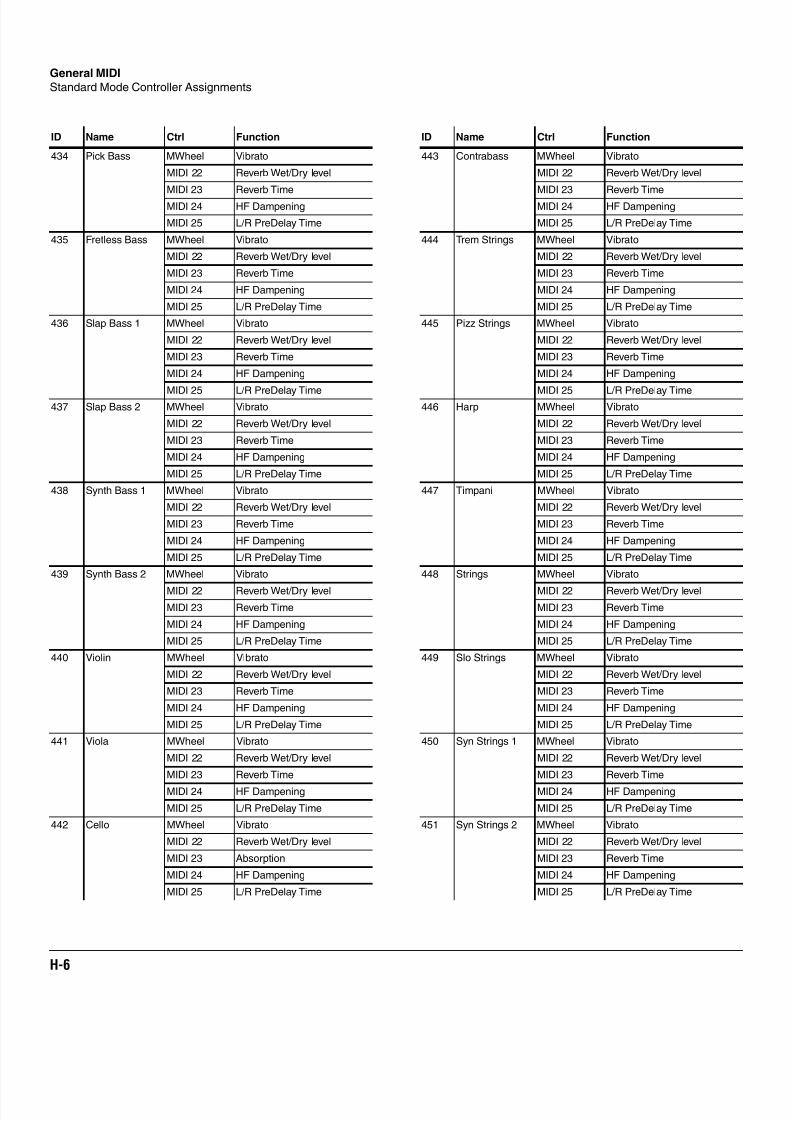
8/21/2019 MR_K2661
http://slidepdf.com/reader/full/mrk2661 484/499
H-6
General MIDI
Standard Mode Controller Assignments
434 Pick Bass MWheel Vibrato
MIDI 22 Reverb Wet/Dry level
MIDI 23 Reverb Time
MIDI 24 HF Dampening
MIDI 25 L/R PreDelay Time
435 Fretless Bass MWheel Vibrato
MIDI 22 Reverb Wet/Dry level
MIDI 23 Reverb Time
MIDI 24 HF Dampening
MIDI 25 L/R PreDelay Time
436 Slap Bass 1 MWheel Vibrato
MIDI 22 Reverb Wet/Dry level
MIDI 23 Reverb Time
MIDI 24 HF Dampening
MIDI 25 L/R PreDelay Time437 Slap Bass 2 MWheel Vibrato
MIDI 22 Reverb Wet/Dry level
MIDI 23 Reverb Time
MIDI 24 HF Dampening
MIDI 25 L/R PreDelay Time
438 Synth Bass 1 MWheel Vibrato
MIDI 22 Reverb Wet/Dry level
MIDI 23 Reverb Time
MIDI 24 HF Dampening
MIDI 25 L/R PreDelay Time
439 Synth Bass 2 MWheel Vibrato
MIDI 22 Reverb Wet/Dry level
MIDI 23 Reverb Time
MIDI 24 HF Dampening
MIDI 25 L/R PreDelay Time
440 Violin MWheel Vibrato
MIDI 22 Reverb Wet/Dry level
MIDI 23 Reverb Time
MIDI 24 HF Dampening
MIDI 25 L/R PreDelay Time
441 Viola MWheel Vibrato
MIDI 22 Reverb Wet/Dry level
MIDI 23 Reverb Time
MIDI 24 HF Dampening
MIDI 25 L/R PreDelay Time
442 Cello MWheel Vibrato
MIDI 22 Reverb Wet/Dry level
MIDI 23 Absorption
MIDI 24 HF Dampening
MIDI 25 L/R PreDelay Time
ID Name Ctrl Function
443 Contrabass MWheel Vibrato
MIDI 22 Reverb Wet/Dry level
MIDI 23 Reverb Time
MIDI 24 HF Dampening
MIDI 25 L/R PreDelay Time
444 Trem Strings MWheel Vibrato
MIDI 22 Reverb Wet/Dry level
MIDI 23 Reverb Time
MIDI 24 HF Dampening
MIDI 25 L/R PreDelay Time
445 Pizz Strings MWheel Vibrato
MIDI 22 Reverb Wet/Dry level
MIDI 23 Reverb Time
MIDI 24 HF Dampening
MIDI 25 L/R PreDelay Time446 Harp MWheel Vibrato
MIDI 22 Reverb Wet/Dry level
MIDI 23 Reverb Time
MIDI 24 HF Dampening
MIDI 25 L/R PreDelay Time
447 Timpani MWheel Vibrato
MIDI 22 Reverb Wet/Dry level
MIDI 23 Reverb Time
MIDI 24 HF Dampening
MIDI 25 L/R PreDelay Time
448 Strings MWheel Vibrato
MIDI 22 Reverb Wet/Dry level
MIDI 23 Reverb Time
MIDI 24 HF Dampening
MIDI 25 L/R PreDelay Time
449 Slo Strings MWheel Vibrato
MIDI 22 Reverb Wet/Dry level
MIDI 23 Reverb Time
MIDI 24 HF Dampening
MIDI 25 L/R PreDelay Time
450 Syn Strings 1 MWheel Vibrato
MIDI 22 Reverb Wet/Dry level
MIDI 23 Reverb Time
MIDI 24 HF Dampening
MIDI 25 L/R PreDelay Time
451 Syn Strings 2 MWheel Vibrato
MIDI 22 Reverb Wet/Dry level
MIDI 23 Reverb Time
MIDI 24 HF Dampening
MIDI 25 L/R PreDelay Time
ID Name Ctrl Function
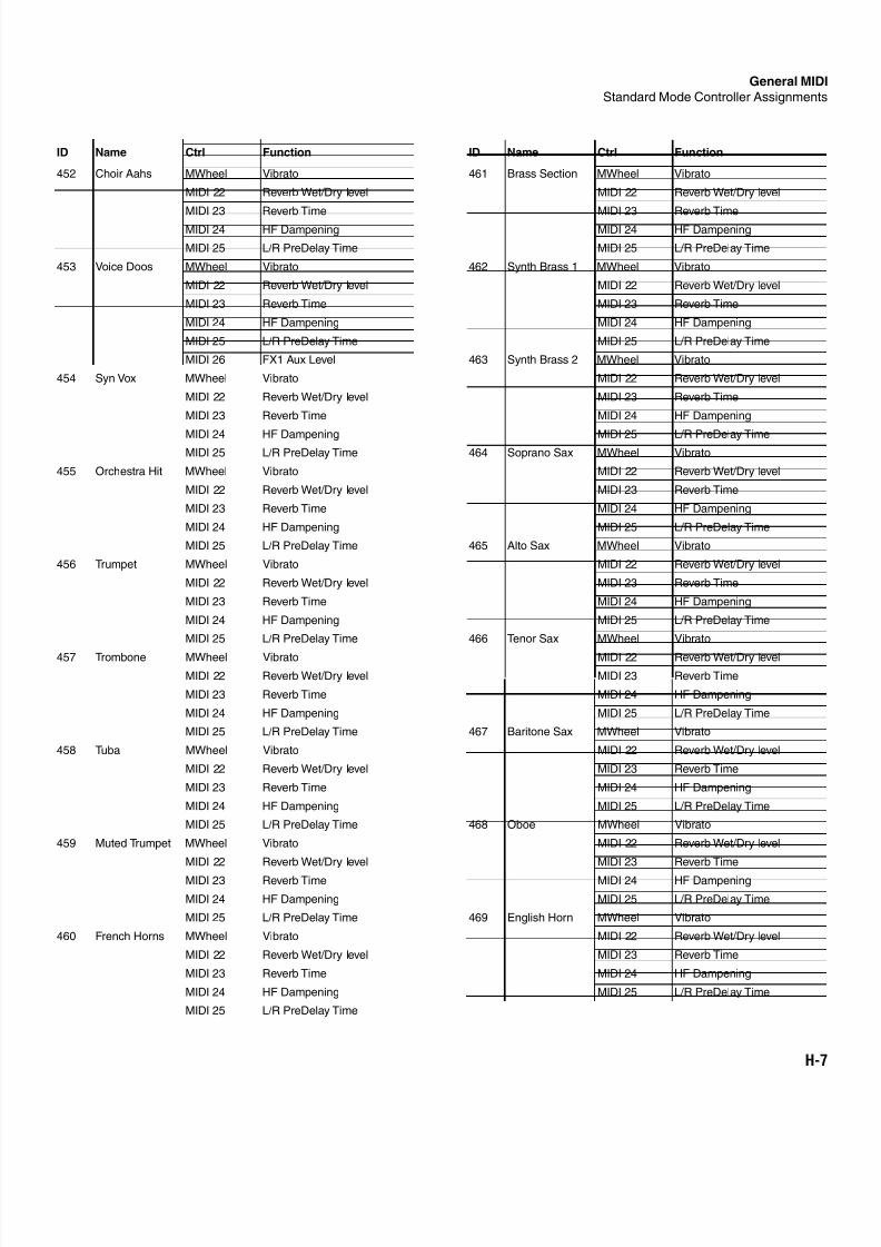
8/21/2019 MR_K2661
http://slidepdf.com/reader/full/mrk2661 485/499
General MID
Standard Mode Controller Assignments
H-7
452 Choir Aahs MWheel Vibrato
MIDI 22 Reverb Wet/Dry level
MIDI 23 Reverb Time
MIDI 24 HF Dampening
MIDI 25 L/R PreDelay Time
453 Voice Doos MWheel Vibrato
MIDI 22 Reverb Wet/Dry level
MIDI 23 Reverb Time
MIDI 24 HF Dampening
MIDI 25 L/R PreDelay Time
MIDI 26 FX1 Aux Level
454 Syn Vox MWheel Vibrato
MIDI 22 Reverb Wet/Dry level
MIDI 23 Reverb Time
MIDI 24 HF DampeningMIDI 25 L/R PreDelay Time
455 Orchestra Hit MWheel Vibrato
MIDI 22 Reverb Wet/Dry level
MIDI 23 Reverb Time
MIDI 24 HF Dampening
MIDI 25 L/R PreDelay Time
456 Trumpet MWheel Vibrato
MIDI 22 Reverb Wet/Dry level
MIDI 23 Reverb Time
MIDI 24 HF Dampening
MIDI 25 L/R PreDelay Time
457 Trombone MWheel Vibrato
MIDI 22 Reverb Wet/Dry level
MIDI 23 Reverb Time
MIDI 24 HF Dampening
MIDI 25 L/R PreDelay Time
458 Tuba MWheel Vibrato
MIDI 22 Reverb Wet/Dry level
MIDI 23 Reverb Time
MIDI 24 HF Dampening
MIDI 25 L/R PreDelay Time
459 Muted Trumpet MWheel Vibrato
MIDI 22 Reverb Wet/Dry level
MIDI 23 Reverb Time
MIDI 24 HF Dampening
MIDI 25 L/R PreDelay Time
460 French Horns MWheel Vibrato
MIDI 22 Reverb Wet/Dry level
MIDI 23 Reverb Time
MIDI 24 HF Dampening
MIDI 25 L/R PreDelay Time
ID Name Ctrl Function
461 Brass Section MWheel Vibrato
MIDI 22 Reverb Wet/Dry level
MIDI 23 Reverb Time
MIDI 24 HF Dampening
MIDI 25 L/R PreDelay Time
462 Synth Brass 1 MWheel Vibrato
MIDI 22 Reverb Wet/Dry level
MIDI 23 Reverb Time
MIDI 24 HF Dampening
MIDI 25 L/R PreDelay Time
463 Synth Brass 2 MWheel Vibrato
MIDI 22 Reverb Wet/Dry level
MIDI 23 Reverb Time
MIDI 24 HF Dampening
MIDI 25 L/R PreDelay Time464 Soprano Sax MWheel Vibrato
MIDI 22 Reverb Wet/Dry level
MIDI 23 Reverb Time
MIDI 24 HF Dampening
MIDI 25 L/R PreDelay Time
465 Alto Sax MWheel Vibrato
MIDI 22 Reverb Wet/Dry level
MIDI 23 Reverb Time
MIDI 24 HF Dampening
MIDI 25 L/R PreDelay Time
466 Tenor Sax MWheel Vibrato
MIDI 22 Reverb Wet/Dry level
MIDI 23 Reverb Time
MIDI 24 HF Dampening
MIDI 25 L/R PreDelay Time
467 Baritone Sax MWheel Vibrato
MIDI 22 Reverb Wet/Dry level
MIDI 23 Reverb Time
MIDI 24 HF Dampening
MIDI 25 L/R PreDelay Time
468 Oboe MWheel Vibrato
MIDI 22 Reverb Wet/Dry level
MIDI 23 Reverb Time
MIDI 24 HF Dampening
MIDI 25 L/R PreDelay Time
469 English Horn MWheel Vibrato
MIDI 22 Reverb Wet/Dry level
MIDI 23 Reverb Time
MIDI 24 HF Dampening
MIDI 25 L/R PreDelay Time
ID Name Ctrl Function
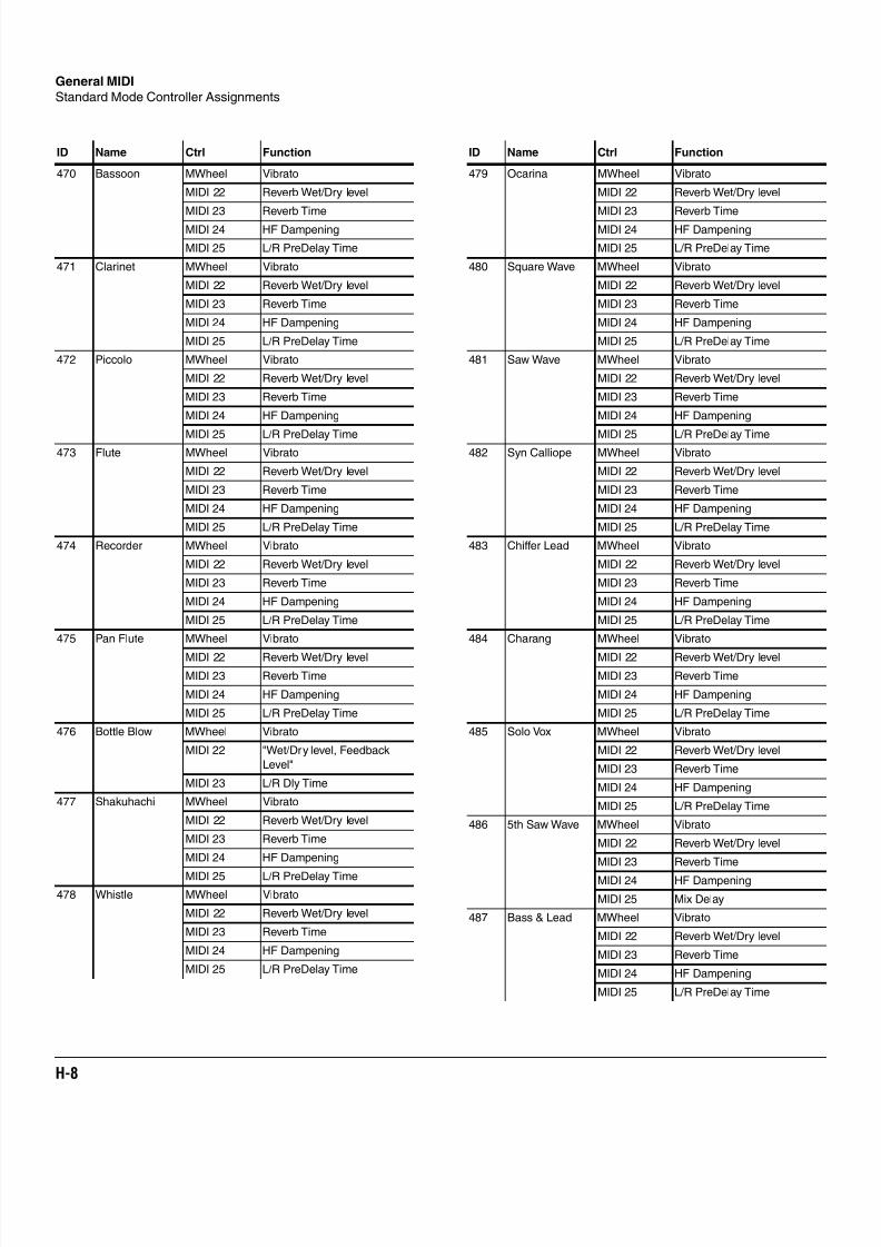
8/21/2019 MR_K2661
http://slidepdf.com/reader/full/mrk2661 486/499
H-8
General MIDI
Standard Mode Controller Assignments
470 Bassoon MWheel Vibrato
MIDI 22 Reverb Wet/Dry level
MIDI 23 Reverb Time
MIDI 24 HF Dampening
MIDI 25 L/R PreDelay Time
471 Clarinet MWheel Vibrato
MIDI 22 Reverb Wet/Dry level
MIDI 23 Reverb Time
MIDI 24 HF Dampening
MIDI 25 L/R PreDelay Time
472 Piccolo MWheel Vibrato
MIDI 22 Reverb Wet/Dry level
MIDI 23 Reverb Time
MIDI 24 HF Dampening
MIDI 25 L/R PreDelay Time473 Flute MWheel Vibrato
MIDI 22 Reverb Wet/Dry level
MIDI 23 Reverb Time
MIDI 24 HF Dampening
MIDI 25 L/R PreDelay Time
474 Recorder MWheel Vibrato
MIDI 22 Reverb Wet/Dry level
MIDI 23 Reverb Time
MIDI 24 HF Dampening
MIDI 25 L/R PreDelay Time
475 Pan Flute MWheel Vibrato
MIDI 22 Reverb Wet/Dry level
MIDI 23 Reverb Time
MIDI 24 HF Dampening
MIDI 25 L/R PreDelay Time
476 Bottle Blow MWheel Vibrato
MIDI 22 "Wet/Dry level, Feedback
Level"
MIDI 23 L/R Dly Time
477 Shakuhachi MWheel Vibrato
MIDI 22 Reverb Wet/Dry level
MIDI 23 Reverb Time
MIDI 24 HF Dampening
MIDI 25 L/R PreDelay Time
478 Whistle MWheel Vibrato
MIDI 22 Reverb Wet/Dry level
MIDI 23 Reverb Time
MIDI 24 HF Dampening
MIDI 25 L/R PreDelay Time
ID Name Ctrl Function
479 Ocarina MWheel Vibrato
MIDI 22 Reverb Wet/Dry level
MIDI 23 Reverb Time
MIDI 24 HF Dampening
MIDI 25 L/R PreDelay Time
480 Square Wave MWheel Vibrato
MIDI 22 Reverb Wet/Dry level
MIDI 23 Reverb Time
MIDI 24 HF Dampening
MIDI 25 L/R PreDelay Time
481 Saw Wave MWheel Vibrato
MIDI 22 Reverb Wet/Dry level
MIDI 23 Reverb Time
MIDI 24 HF Dampening
MIDI 25 L/R PreDelay Time482 Syn Calliope MWheel Vibrato
MIDI 22 Reverb Wet/Dry level
MIDI 23 Reverb Time
MIDI 24 HF Dampening
MIDI 25 L/R PreDelay Time
483 Chiffer Lead MWheel Vibrato
MIDI 22 Reverb Wet/Dry level
MIDI 23 Reverb Time
MIDI 24 HF Dampening
MIDI 25 L/R PreDelay Time
484 Charang MWheel Vibrato
MIDI 22 Reverb Wet/Dry level
MIDI 23 Reverb Time
MIDI 24 HF Dampening
MIDI 25 L/R PreDelay Time
485 Solo Vox MWheel Vibrato
MIDI 22 Reverb Wet/Dry level
MIDI 23 Reverb Time
MIDI 24 HF Dampening
MIDI 25 L/R PreDelay Time
486 5th Saw Wave MWheel Vibrato
MIDI 22 Reverb Wet/Dry level
MIDI 23 Reverb Time
MIDI 24 HF Dampening
MIDI 25 Mix Delay
487 Bass & Lead MWheel Vibrato
MIDI 22 Reverb Wet/Dry level
MIDI 23 Reverb Time
MIDI 24 HF Dampening
MIDI 25 L/R PreDelay Time
ID Name Ctrl Function
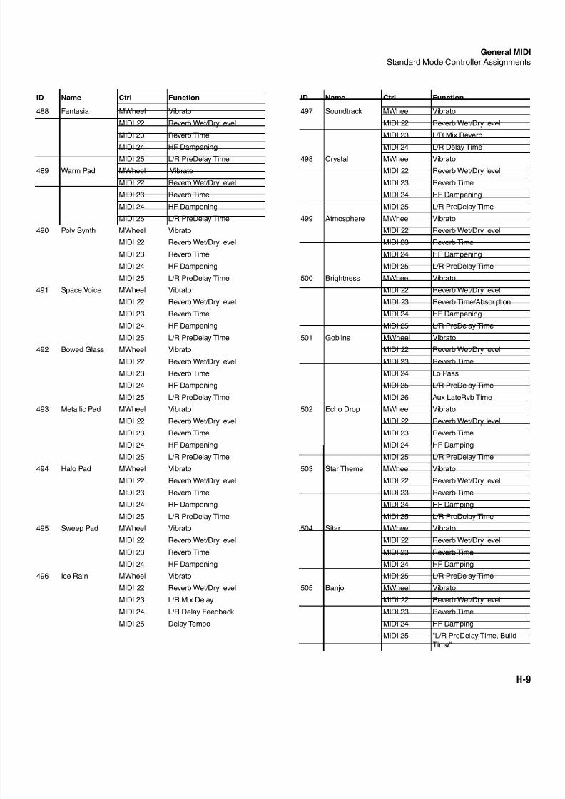
8/21/2019 MR_K2661
http://slidepdf.com/reader/full/mrk2661 487/499
General MID
Standard Mode Controller Assignments
H-9
488 Fantasia MWheel Vibrato
MIDI 22 Reverb Wet/Dry level
MIDI 23 Reverb Time
MIDI 24 HF Dampening
MIDI 25 L/R PreDelay Time
489 Warm Pad MWheel Vibrato
MIDI 22 Reverb Wet/Dry level
MIDI 23 Reverb Time
MIDI 24 HF Dampening
MIDI 25 L/R PreDelay Time
490 Poly Synth MWheel Vibrato
MIDI 22 Reverb Wet/Dry level
MIDI 23 Reverb Time
MIDI 24 HF Dampening
MIDI 25 L/R PreDelay Time491 Space Voice MWheel Vibrato
MIDI 22 Reverb Wet/Dry level
MIDI 23 Reverb Time
MIDI 24 HF Dampening
MIDI 25 L/R PreDelay Time
492 Bowed Glass MWheel Vibrato
MIDI 22 Reverb Wet/Dry level
MIDI 23 Reverb Time
MIDI 24 HF Dampening
MIDI 25 L/R PreDelay Time
493 Metallic Pad MWheel Vibrato
MIDI 22 Reverb Wet/Dry level
MIDI 23 Reverb Time
MIDI 24 HF Dampening
MIDI 25 L/R PreDelay Time
494 Halo Pad MWheel Vibrato
MIDI 22 Reverb Wet/Dry level
MIDI 23 Reverb Time
MIDI 24 HF Dampening
MIDI 25 L/R PreDelay Time
495 Sweep Pad MWheel Vibrato
MIDI 22 Reverb Wet/Dry level
MIDI 23 Reverb Time
MIDI 24 HF Dampening
496 Ice Rain MWheel Vibrato
MIDI 22 Reverb Wet/Dry level
MIDI 23 L/R Mix Delay
MIDI 24 L/R Delay Feedback
MIDI 25 Delay Tempo
ID Name Ctrl Function
497 Soundtrack MWheel Vibrato
MIDI 22 Reverb Wet/Dry level
MIDI 23 L/R Mix Reverb
MIDI 24 L/R Delay Time
498 Crystal MWheel Vibrato
MIDI 22 Reverb Wet/Dry level
MIDI 23 Reverb Time
MIDI 24 HF Dampening
MIDI 25 L/R PreDelay Time
499 Atmosphere MWheel Vibrato
MIDI 22 Reverb Wet/Dry level
MIDI 23 Reverb Time
MIDI 24 HF Dampening
MIDI 25 L/R PreDelay Time
500 Brightness MWheel VibratoMIDI 22 Reverb Wet/Dry level
MIDI 23 Reverb Time/Absorption
MIDI 24 HF Dampening
MIDI 25 L/R PreDelay Time
501 Goblins MWheel Vibrato
MIDI 22 Reverb Wet/Dry level
MIDI 23 Reverb Time
MIDI 24 Lo Pass
MIDI 25 L/R PreDelay Time
MIDI 26 Aux LateRvb Time
502 Echo Drop MWheel Vibrato
MIDI 22 Reverb Wet/Dry level
MIDI 23 Reverb Time
MIDI 24 HF Damping
MIDI 25 L/R PreDelay Time
503 Star Theme MWheel Vibrato
MIDI 22 Reverb Wet/Dry level
MIDI 23 Reverb Time
MIDI 24 HF Damping
MIDI 25 L/R PreDelay Time
504 Sitar MWheel Vibrato
MIDI 22 Reverb Wet/Dry level
MIDI 23 Reverb Time
MIDI 24 HF Damping
MIDI 25 L/R PreDelay Time
505 Banjo MWheel Vibrato
MIDI 22 Reverb Wet/Dry level
MIDI 23 Reverb Time
MIDI 24 HF Damping
MIDI 25 "L/R PreDelay Time, Build
Time"
ID Name Ctrl Function
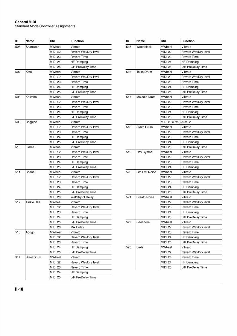
8/21/2019 MR_K2661
http://slidepdf.com/reader/full/mrk2661 488/499
H-10
General MIDI
Standard Mode Controller Assignments
506 Shamisen MWheel Vibrato
MIDI 22 Reverb Wet/Dry level
MIDI 23 Reverb Time
MIDI 24 HF Damping
MIDI 25 L/R PreDelay Time
507 Koto MWheel Vibrato
MIDI 22 Reverb Wet/Dry level
MIDI 23 Reverb Time
MIDI 24 HF Damping
MIDI 25 L/R PreDelay Time
508 Kalimba MWheel Vibrato
MIDI 22 Reverb Wet/Dry level
MIDI 23 Reverb Time
MIDI 24 HF Damping
MIDI 25 L/R PreDelay Time509 Bagpipe MWheel Vibrato
MIDI 22 Reverb Wet/Dry level
MIDI 23 Reverb Time
MIDI 24 HF Damping
MIDI 25 L/R PreDelay Time
510 Fiddle MWheel Vibrato
MIDI 22 Reverb Wet/Dry level
MIDI 23 Reverb Time
MIDI 24 HF Damping
MIDI 25 L/R PreDelay Time
511 Shanai MWheel Vibrato
MIDI 22 Reverb Wet/Dry level
MIDI 23 Reverb Time
MIDI 24 HF Damping
MIDI 25 L/R PreDelay Time
MIDI 26 Wet/Dry of Delay
512 Tinkle Bell MWheel Vibrato
MIDI 22 Reverb Wet/Dry level
MIDI 23 Reverb Time
MIDI 24 HF Damping
MIDI 25 L/R PreDelay Time
MIDI 26 Mix Delay
513 Agogo MWheel Vibrato
MIDI 22 Reverb Wet/Dry level
MIDI 23 Reverb Time
MIDI 24 HF Damping
MIDI 25 L/R PreDelay Time
514 Steel Drum MWheel Vibrato
MIDI 22 Reverb Wet/Dry level
MIDI 23 Reverb Time
MIDI 24 HF Damping
MIDI 25 L/R PreDelay Time
ID Name Ctrl Function
515 Woodblock MWheel Vibrato
MIDI 22 Reverb Wet/Dry level
MIDI 23 Reverb Time
MIDI 24 HF Damping
MIDI 25 L/R PreDelay Time
516 Taiko Drum MWheel Vibrato
MIDI 22 Reverb Wet/Dry level
MIDI 23 Reverb Time
MIDI 24 HF Damping
MIDI 25 L/R PreDelay Time
517 Melodic Drum MWheel Vibrato
MIDI 22 Reverb Wet/Dry level
MIDI 23 Reverb Time
MIDI 24 HF Damping
MIDI 25 L/R PreDelay TimeMIDI 29 (Sw2) Aux Lvl
518 Synth Drum MWheel Vibrato
MIDI 22 Reverb Wet/Dry level
MIDI 23 Reverb Time
MIDI 24 HF Damping
MIDI 25 L/R PreDelay Time
519 Rev Cymbal MWheel Vibrato
MIDI 22 Reverb Wet/Dry level
MIDI 23 Reverb Time
MIDI 24 HF Damping
520 Gtr. Fret Noise MWheel Vibrato
MIDI 22 Reverb Wet/Dry level
MIDI 23 Reverb Time
MIDI 24 HF Damping
MIDI 25 L/R PreDelay Time
521 Breath Noise MWheel Vibrato
MIDI 22 Reverb Wet/Dry level
MIDI 23 Reverb Time
MIDI 24 HF Damping
MIDI 25 L/R PreDelay Time
522 Seashore MWheel Vibrato
MIDI 22 Reverb Wet/Dry level
MIDI 23 Reverb Time
MIDI 24 HF Damping
MIDI 25 L/R PreDelay Time
523 Birds MWheel Vibrato
MIDI 22 Reverb Wet/Dry level
MIDI 23 Reverb Time
MIDI 24 HF Damping
MIDI 25 L/R PreDelay Time
ID Name Ctrl Function
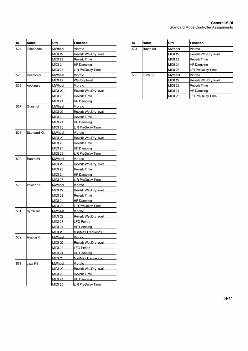
8/21/2019 MR_K2661
http://slidepdf.com/reader/full/mrk2661 489/499
General MID
Standard Mode Controller Assignments
H-11
524 Telephone MWheel Vibrato
MIDI 22 Reverb Wet/Dry level
MIDI 23 Reverb Time
MIDI 24 HF Damping
MIDI 25 L/R PreDelay Time
525 Helicopter MWheel Vibrato
MIDI 22 Wet/Dry level
526 Applause MWheel Vibrato
MIDI 22 Reverb Wet/Dry level
MIDI 23 Reverb Time
MIDI 24 HF Damping
527 Gunshot MWheel Vibrato
MIDI 22 Reverb Wet/Dry level
MIDI 23 Reverb Time
MIDI 24 HF DampingMIDI 25 L/R PreDelay Time
528 Standard Kit MWheel Vibrato
MIDI 22 Reverb Wet/Dry level
MIDI 23 Reverb Time
MIDI 24 HF Damping
MIDI 25 L/R PreDelay Time
529 Room Kit MWheel Vibrato
MIDI 22 Reverb Wet/Dry level
MIDI 23 Reverb Time
MIDI 24 HF Damping
MIDI 25 L/R PreDelay Time
530 Power Kit MWheel Vibrato
MIDI 22 Reverb Wet/Dry level
MIDI 23 Reverb Time
MIDI 24 HF Damping
MIDI 25 L/R PreDelay Time
531 Synth Kit MWheel Vibrato
MIDI 22 Reverb Wet/Dry level
MIDI 23 LFO Period
MIDI 24 HF Damping
MIDI 25 Min/Max Frequency
532 Analog Kit MWheel Vibrato
MIDI 22 Reverb Wet/Dry level
MIDI 23 LFO Period
MIDI 24 HF Damping
MIDI 25 Min/Max Frequency
533 Jazz Kit MWheel Vibrato
MIDI 22 Reverb Wet/Dry level
MIDI 23 Reverb Time
MIDI 24 HF Damping
MIDI 25 L/R PreDelay Time
ID Name Ctrl Function
534 Brush Kit MWheel Vibrato
MIDI 22 Reverb Wet/Dry level
MIDI 23 Reverb Time
MIDI 24 HF Damping
MIDI 25 L/R PreDelay Time
535 Orch Kit MWheel Vibrato
MIDI 22 Reverb Wet/Dry level
MIDI 23 Reverb Time
MIDI 24 HF Damping
MIDI 25 L/R PreDelay Time
ID Name Ctrl Function

8/21/2019 MR_K2661
http://slidepdf.com/reader/full/mrk2661 490/499
H-12
General MIDI
Standard Mode Controller Assignments
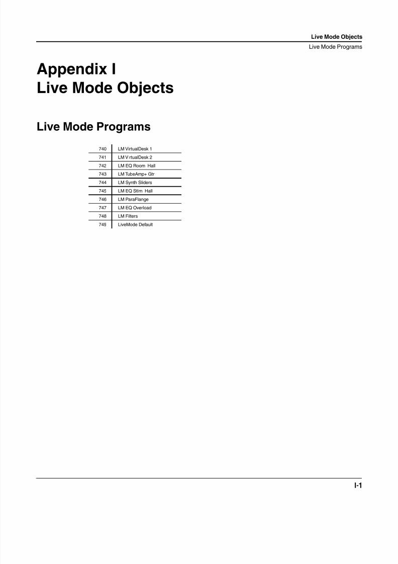
8/21/2019 MR_K2661
http://slidepdf.com/reader/full/mrk2661 491/499
Live Mode Objects
Live Mode Programs
I-1
Appendix I
Live Mode Objects
Live Mode Programs
740 LM VirtualDesk 1
741 LM VirtualDesk 2
742 LM EQ Room Hall
743 LM TubeAmp+ Gtr
744 LM Synth Sliders
745 LM EQ StIm Hall
746 LM ParaFlange
747 LM EQ Overload
748 LM Filters
749 LiveMode Default
8/21/2019 MR_K2661
http://slidepdf.com/reader/full/mrk2661 492/499
I-2
Live Mode Objects
Live Mode Programs
8/21/2019 MR_K2661
http://slidepdf.com/reader/full/mrk2661 493/499
K2661 Musician’s Reference
Index
Index
Numerics2 Band Enhancer 10-2223 Band Enhancer 10-2243 Band EQ 10-2433 Band Shaper 10-1714-Tap Delay 10-294-Tap Delay BPM 10-295 Band EQ 10-2418-Tap Delay 10-338-Tap Delay BPM 10-33
AA clock 4-10Absolute Pitch Wheel 4-8
ADAT In 8-6ALG page (triples) 12-5algorithm reference (triples) 12-12–12-35
Layer 1 12-12–12-19Layer 2 12-19–12-29Layer 3 12-29–12-35
algorithms for triple-modular processing 12-3Allpass Phaser 3 10-71AMP block 12-6Amplitude envelope 4-13amplitude envelopes 12-6
and the keymap in Layer 3 12-8Apple Macintosh 6-3ASR1, ASR2 4-12Attack state 4-13Attack velocity 4-11AutoPanner 10-228
BB clock 4-10
backward compatibility (triples) 12-3Balance (MIDI 08) 4-6Balance control 4-9Band Compress 10-192Battery replacement 8-2Bipolar attack velocity 4-12Bipolar key number 4-11Bipolar Mod Wheel 4-8Bipolar mono pressure 4-8Bipolar polyphonic pressure 4-12
Breath (MIDI 02) 4-5Buttons
double presses 1-6Bypass effects 1-5
Cchaining DSP functions 12-1Chan/Bank buttons 1-5Channel count 4-9Channel state 4-8Chaos! 10-189
Chor+Dly+Reverb 10-73Chorus 1 10-51Chorus 2 10-51Chorus+4Tap 10-73Chorus+Delay 10-73
Chorus4Tap 10-79ChorusLasrDly 10-79ChorusReverb 10-79Classic Place 10-13Classic Verb 10-13Cleaning your K2500 8-1Comp/Exp + EQ 10-209Compare 1-5compatibility of triples with other Kurzweils 12-3Complex Echo 10-26Composite SIMMs
No, No, No! 9-2Compress 3 Band 10-214Compress w/SC EQ 10-206Compress/Expand 10-209
CompressDualTime 10-196Contemporary ROM D-1Contrast
for display 1-3Control messages
AuxBend2 (MIDI 15) 4-6Balance (MIDI 08) 4-6Breath 4-5Data (MIDI 06) 4-5Data decrement (MIDI 97) 4-7Data increment (MIDI 96) 4-7Effects depth (MIDI 91) 4-7Expression (MIDI 11) 4-6Foot (MIDI 04) 4-5Freeze pedal (MIDI 69) 4-7Legato switch (MIDI 75) 4-7Mod Wheel (MIDI 01) 4-5Mono pressure 4-5Pan (MIDI 10) 4-6Panic (MIDI 123) 4-7Portamento switch (MIDI 65) 4-6Portamento time (MIDI 05) 4-5Soft pedal (MIDI 67) 4-7Sostenuto (MIDI 66) 4-6Sustain (MIDI 64) 4-6Volume (MIDI 07) 4-5
Control source lists 4-3Control sources 4-1
A clock 4-10Absolute Pitch Wheel 4-8Amplitude envelope 4-13
ASR1, ASR2 4-12Attack state 4-13Attack velocity 4-11B clock 4-10Balance control 4-9Bipolar attack velocity 4-12Bipolar key number 4-11Bipolar Mod Wheel 4-8Bipolar mono pressure 4-8Bipolar polyphonic pressure 4-12Channel count 4-9Channel state 4-8Constants for FUNS 4-15
8/21/2019 MR_K2661
http://slidepdf.com/reader/full/mrk2661 494/499
K2661 Musician’s Reference
Index
Envelopes 2 and 3 4-13FUN1, FUN2 4-12FUN3, FUN4 4-13GAttVel 4-14GKeyNum 4-14
Global ASR2 4-9Global FUN2 4-9Global FUN4 4-9Global LFO2 4-9Global LFOphase 4-9Global phase 1 and 2 4-11Inverse attack velocity 4-12Key number 4-11Key state 4-11LFO1 4-12LFO1 phase 4-13LFO2 4-13Loop state 4-13Mono pressure 4-8Negative A clock 4-10
Negative B clock 4-10Note state 4-11-ON 4-14ON 4-14Pan control 4-9Pitch Wheel 4-8Polyphonic pressure 4-12Random variants 1 and 2 4-12Release state 4-14Release velocity 4-12Sample playback rate 4-13Sync state 4-10Velocity triggers 1 and 2 4-12Volume control 4-9
copying triples 12-4creating triples 12-4
DData (MIDI 06) 4-5Data decrement (MIDI 97) 4-7Data increment (MIDI 96) 4-7Degen Regen BPM 10-42Descriptions of control sources 4-4Diagnostics 8-3diagram of triple 12-1diagrams of triple algorithms 12-12–12-35
Layer 1 12-12–12-19Layer 2 12-19–12-29Layer 3 12-29–12-35
different algorithms for different layers 12-3
Diffuse Place 10-13Diffuse Verb 10-13Disk button 1-5Disk Size Restrictions 6-1Display
contrast 1-3Distort + Rotary 10-111Double button presses 1-6DSP waveforms 12-10Dual AutoPanner 10-230Dual Chorus 1 10-51Dual Chorus 2 10-51Dual Graphic EQ 10-238
Dual MiniVerb 10-6Dual MovDelay 10-93Dual Res Filter 10-156Dumping samples via SMDI 6-8
EEdit button 1-5Edit compare 1-5editing triples 12-5Effects button 1-5Effects bypass 1-5Effects depth (MIDI 91) 4-7Env Follow Filt 10-148Envelopes 2 and 3 4-13EQ Morpher 10-158Expander 10-203Expression (MIDI 11) 4-6
FFinite Verb 10-24Flan+Dly+Reverb 10-73Flange+4Tap 10-73Flange+Delay 10-73Flange4Tap 10-79FlangeLasrDly 10-79FlangePitcher 10-79Flanger 1 10-58Flanger 2 10-58FlangeReverb 10-79FlangeShaper 10-79Foot (MIDI 04) 4-5Freeze pedal (MIDI 69) 4-7Frequency Offset 10-183
Front panel reference 1-1FUN1, FUN2 4-12FUN3, FUN4 4-13FX bypass 1-5FX presets (ROM), list 10-3FXMod Diagnostic 10-249
GGate 10-217Gate+Cmp[EQ]+Vrb 10-141Gate+TubeAmp 10-145Gated LaserVerb 10-178Gated MiniVerb 10-10GAttVel control source 4-14GKeyNum control source 4-14Global ASR2 4-9Global FUN2 4-9Global FUN4 4-9Global LFO phase 4-9Global LFO2 4-9Global phase 1 and 2 4-11Global random variant 1 and 2 4-11Grand Plate 10-22Graphic EQ 10-238Ground hum 8-4
8/21/2019 MR_K2661
http://slidepdf.com/reader/full/mrk2661 495/499
K2661 Musician’s Reference
Index
HHard Reset G-2HardKnee Compress 10-200HarmonicSuppress 10-245
HF Stimulate 1 10-244
Iimporting triples 12-5input and output of triples 12-5input locations (triples) 12-7Inverse attack velocity 4-12
J Jump to page 1-5
K
K2000SysEx compatibility 7-1K2600 Features A-1KB3 AuxFX 10-115KB3 FXBus 10-115KB3 programs and triples 12-2KDFX V2 Algorithms 10-42Key number 4-11Key numbers 5-1Key state 4-11Keymaps (ROM), list D-3, E-3
LLaserVerb 10-172LaserVerb Lite 10-172LasrDlyReverb 10-79layer parameters 12-9Layers
Muting 1-5layers without sound (triples) 12-9Legato switch (MIDI 75) 4-7LFO Phaser 10-65LFO Phaser Twin 10-65LFO shape
Diagrams 2-2Names 2-1
LFO Sweep Filter 10-153LFO1 4-12LFO1 phase 4-13LFO2 4-13
LFO2 phase 4-13List of ROM FX presets 10-3List of ROM Keymaps D-3, E-3List of ROM Programs D-2, E-2List of ROM QA banks D-2, E-2List of ROM Samples D-3, E-3List of ROM Setups D-2, E-2Live mode and triples 12-2Live mode objects I-1Loop state 4-13
MMacintosh Computers and K2600 6-3Main Control Source list 4-8Maintenance and Prevention 8-1
Manual Phaser 10-65Marking pages 1-5Master button 1-5Memory management 9-1MIDI
Key and note numbers 5-1Sample dumps 6-4
MIDI button 1-5MIDI Control Source list 4-5MIDI Implementation Chart A-4MIDI sample dump standard
Aborting 6-7Loading 6-4New samples 6-6Troubleshooting 6-6
MiniVerb 10-6Mod Wheel (MIDI 01) 4-5Mode buttons—Program and Setup Editors 1-4Mono -> Stereo 10-236Mono Distortion 10-98Mono EQ Morpher 10-158Mono LaserVerb 10-172Mono pressure 4-8MonoDistort + Cab 10-98MonoDistort + EQ 10-98MonoPitcher+Chor 10-94MonoPitcher+Flan 10-94Moving Delay 10-50Music workstation ideas 7-1Muting layers 1-5Muting Setup zones 1-5
MutualFreqOffset 10-183
Nnatural amplitude envelope 12-6, 12-8Negative A clock 4-10Negative B clock 4-10new combined DSP functions 12-10new triple 12-4Noise prevention and reduction 8-3NOISE+ (DSP function) 12-10Note numbers 5-1Note numbers, percussion keymaps 5-1Note State 20 4-11note stealing (triples) 12-10
OObjects
RAM, viewing 9-2SysEx values 7-7
OmniPlace 10-13OmniVerb 10-13Orchestral ROM E-1Orchestral ROM Programs with Controller Assignments E-4output parameters 12-9
8/21/2019 MR_K2661
http://slidepdf.com/reader/full/mrk2661 496/499
K2661 Musician’s Reference
Index
Ppadding filter input 12-10Pages
Jumping to 1-5
Marking 1-5Previous 1-5Pan (MIDI 10) 4-6Pan control 4-9Panaural Room 10-16Panic (MIDI 123) 4-7pitch block 12-3Pitch Wheel 4-8Pitcher 10-165Pitcher+Chor+Dly 10-73Pitcher+Flan+Dly 10-73Pitcher+MiniVerb 10-134Poly Pitcher 10-181PolyDistort + EQ 10-103Polyphonic pressure 4-12polyphony (triples) 12-2, 12-10Portamento switch (MIDI 65) 4-6Portamento time (MIDI 05) 4-5Power problems 8-5Previous page 1-5processing-only layers (triples) 12-9Program button 1-5Program RAM vs. Sample RAM 9-1Programs (ROM), list D-2, E-2PWM 12-10
QQA banks (ROM), list D-2, E-2Quad MovDelay 10-93Quantize+Alias 10-131
Quantize+Flange 10-89Quick Access button 1-5
RRAM
Sample vs. Program 9-1RAM objects, viewing 9-2Random variants 1 and 2 4-12Release state 4-14Release velocity 4-12Replacing the battery 8-2Reset
hard G-2Soft 8-5
Resonant Filter 10-156Reverb+Compress 10-137Revrse LaserVerb 10-175Ring Modulator 10-161ROM FX presets, list 10-3ROM Keymaps, list D-3, E-3ROM Programs, list D-2, E-2ROM QA banks, list D-2, E-2ROM Samples, list D-3, E-3ROM Setups, list D-2, E-2ROM4 G-1Rotor 1 10-121
SSample
SMDI transfers 6-8Sample dumps 6-4
Sample ID offset 6-6Sample playback rate 4-13Sample RAM vs. Program RAM 9-1Samples (ROM), list D-3, E-3Scanner Diagnostics 8-3Screen
contrast 1-3SCSI Guidelines 6-1Setup button 1-5Setups
Muting zones 1-5Special-purpose C-2
Setups (ROM), list D-2, E-2ShaperReverb 10-79signal path in triples 12-1SIMMs
for Sample RAM 9-2SingleLFO Phaser 10-65SMDI sample transfers 6-8Soft pedal (MIDI 67) 4-7Soft Reset 8-5
Resetsoft G-5
SoftKneeCompress 10-200soloing and muting triples 12-2Song button 1-5Sostenuto (MIDI 66) 4-6Special button functions 1-4Special-purpose Setups C-2Specifications
K2600 A-1
Spectral 4-Tap 10-37Spectral 6-Tap 10-37SRS 10-233St Chorus+Delay 10-140St Flange+Delay 10-140Standard K2600 ROM Objects C-1Stereo Analyze 10-250Stereo Hall 10-19Stereo Image 10-234stereo keymaps 12-10StereoDistort+EQ 10-98Subtle Distort 10-130Super Gate 10-217Super Shaper 10-170Sustain (MIDI 64) 4-6
Switch Loops 10-47Sync state 4-10System Exclusive
Button press values 7-7Common format 7-1compatibility with K2000 7-1Data formats 7-2Master parameters 7-7Messages 7-3Object types 7-7
System Exclusive implementation 7-1
8/21/2019 MR_K2661
http://slidepdf.com/reader/full/mrk2661 497/499
K2661 Musician’s Reference
Index
TTQ Place 10-13TQ Verb 10-13Tremolo 10-226
Tremolo BPM 10-226TrigEnvelopeFilt 10-150Triple Modular Processing 12-1triple-modular processing 12-1triples 12-1
algorithm reference 12-12–12-35algorithms 12-3amplitude envelopes 12-6
backward compatibility 12-3creating 12-4editing 12-5input and output 12-5input locations 12-7KB3 programs 12-2Live mode 12-2polyphony 12-2polyphony and note stealing 12-10soloing and muting 12-2
Troubleshooting 8-5
Uuser amplitude envelope 12-6, 12-8
VVAST 12-1VC+Dist+1Rotor 2 10-121VC+Dist+HiLoRot2 10-121VC+Dist+HiLoRotr 10-121VC+Tube+Rotor 4 10-121
Velocity triggers 1 and 2 4-12VibChor+Rotor 2 10-106VibChor+Rotor 4 10-106Vibrato Phaser 10-65Viewing RAM objects 9-2Vintage Electric Pianos ROM G-1Volume (MIDI 07) 4-5Volume control 4-9
WWackedPitchLFO 10-187waveforms in triples 12-10When to Use AMP Blocks in Layers 1 and 2 12-6Wrong sample being dumped 6-6
YYoung Chang Distributors iv

8/21/2019 MR_K2661
http://slidepdf.com/reader/full/mrk2661 498/499
K2661 Musician’s Reference
Index
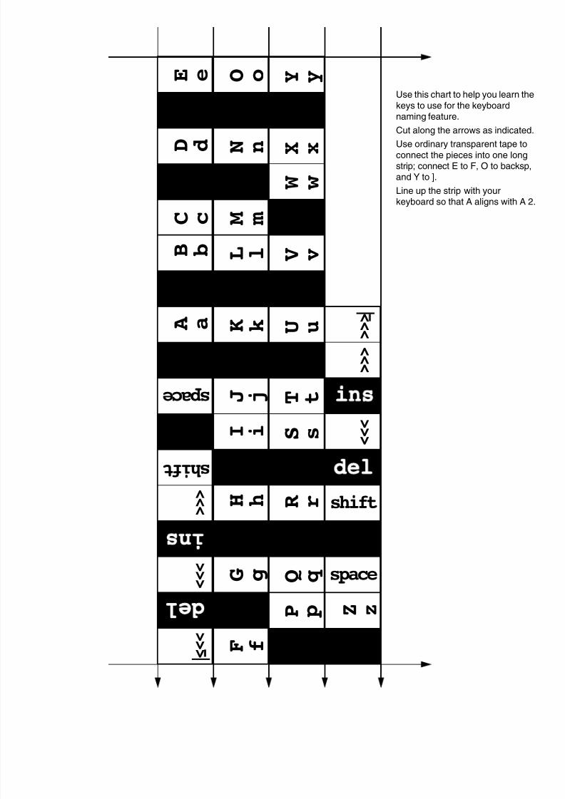
8/21/2019 MR_K2661
http://slidepdf.com/reader/full/mrk2661 499/499
A a
B b
C c
D d
E e
# 3
$ 4
% 5
O o
N n
M m
L l
K k
) 0
_ -
+ =
Y y
X x
W w
V v
U u
> .
? /
` [
> > |
Use this chart to help you learn th
keys to use for the keyboardnaming feature.
Cut along the arrows as indicated
Use ordinary transparent tape to
connect the pieces into one longstrip; connect E to F, O to backspand Y to ].
Line up the strip with yourkeyboard so that A aligns with A


