Embed Size (px)
Citation preview
MS Series Mixed Signal Oscilloscopes
Complete Embedded System Test Analog. Digital. Serial.
2
The Ultimate Mixed Signal Oscilloscope
Unmatched Digital Performance
The MS Series offers unmatched digital
performance and is available in two
models, the MS-500 and MS-250.
Designed to capture long records of
the fastest digital signals the MS-500
has a maximum input frequency of
500 MHz, while other MSOs are
limited to only 250 MHz. The long
memory of 50 Mpts/Ch means that
these fast signals can be captured for
up to 25 ms at up to 2 GS/s sampling
rate. On top of this raw performance,
the MS-500 supports up to 36 channels
—enough for all the ADDR, DATA,
control lines and serial data busses.
This makes it the perfect tool for
embedded systems with 16-bit or
32-bit microcontrollers.
The MS-250 is the ideal tool for testing
embedded systems with 8-bit micro-
controllers or slower digital signals.
With 250 MHz max. input frequency,
18 channels and 10 Mpts/Ch memory
the MS-250 is an outstanding value
and provides a complete set of tools
for embedded system testing.
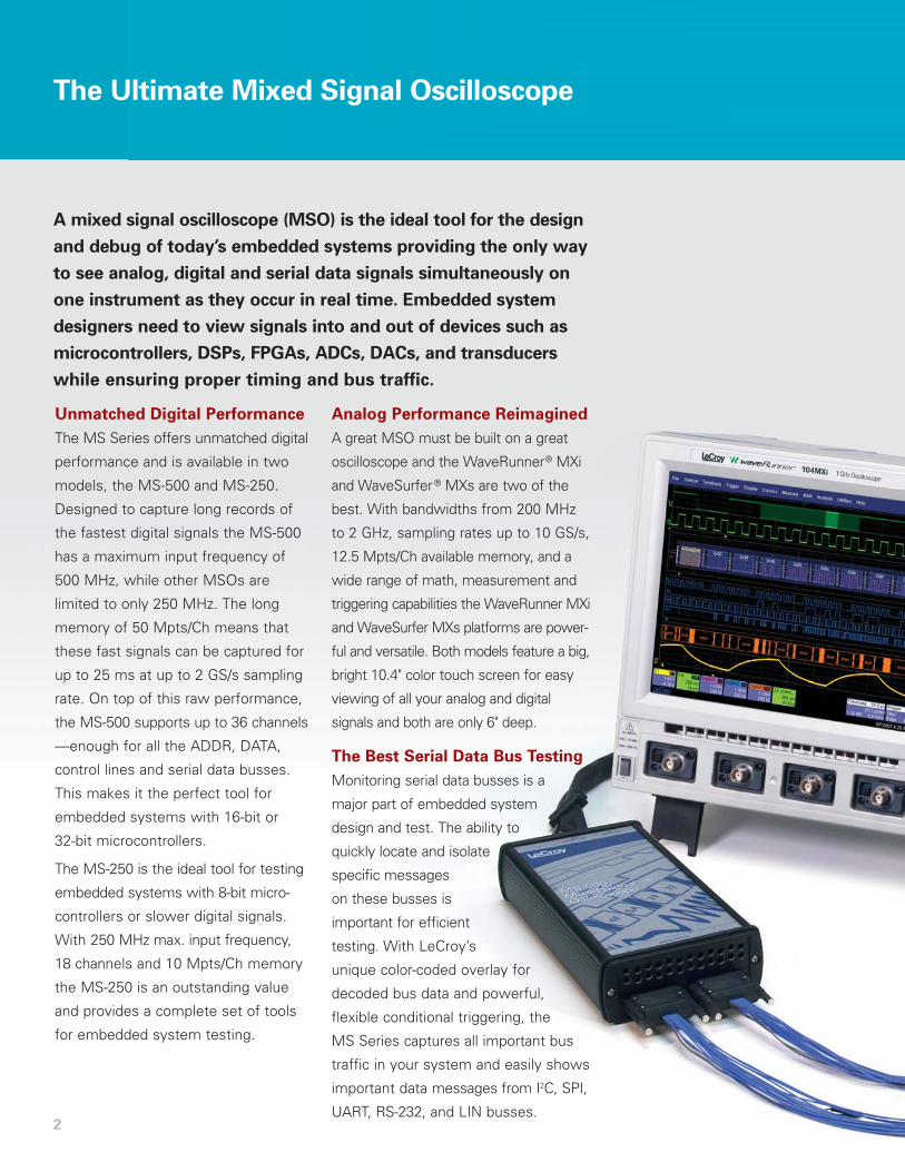
Analog Performance Reimagined
A great MSO must be built on a great
oscilloscope and the WaveRunner® MXi
and WaveSurfer® MXs are two of the
best. With bandwidths from 200 MHz
to 2 GHz, sampling rates up to 10 GS/s,
12.5 Mpts/Ch available memory, and a
wide range of math, measurement and
triggering capabilities the WaveRunner MXi
and WaveSurfer MXs platforms are power-
ful and versatile. Both models feature a big,
bright 10.4" color touch screen for easy
viewing of all your analog and digital
signals and both are only 6" deep.
The Best Serial Data Bus Testing
Monitoring serial data busses is a
major part of embedded system
design and test. The ability to
quickly locate and isolate
specific messages
on these busses is
important for efficient
testing. With LeCroy’s
unique color-coded overlay for
decoded bus data and powerful,
flexible conditional triggering, the
MS Series captures all important bus
traffic in your system and easily shows
important data messages from I2C, SPI,
UART, RS-232, and LIN busses.
A mixed signal oscilloscope (MSO) is the ideal tool for the design
and debug of today’s embedded systems providing the only way
to see analog, digital and serial data signals simultaneously on
one instrument as they occur in real time. Embedded system
designers need to view signals into and out of devices such as
microcontrollers, DSPs, FPGAs, ADCs, DACs, and transducers
while ensuring proper timing and bus traffic.
3
Easy-to-use Measurement Tools
Cursors and measurement parametersare an important part of any oscillo-
scope. When using the MS Seriesthese tools measure digital chan-nels as well analog channels.
Cursors read out hexadecimal bus valueswhile parameters make timing meas-urements on a single digital channel,between two digital channels or evenbetween an analog and a digital channel.
The Complete Mixed Signal Toolset
Analog, Digital and
Cross-pattern Triggering
The WaveRunner MXi and
WaveSurfer MXs oscilloscopes
come with an extensive set of
triggering capabilities aimed at
capturing a wide range of analog
signals. With the MS Series this
triggering is enhanced, adding
analog/digital cross-pattern
trigger, analog/digital event
triggering and the capability to
select any digital channel as the
source for an analog trigger.
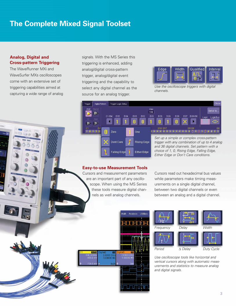
Use the oscilloscope triggers with digitalchannels.
Set up a simple or complex cross-patterntrigger with any combination of up to 4 analogand 36 digital channels. Set pattern with achoice of 1, 0, Rising Edge, Falling Edge,Either Edge or Don’t Care conditions.
Use oscilloscope tools like horizontal and vertical cursors along with automatic meas-urements and statistics to measure analogand digital signals.
Frequency Delay Width
Period Δ Delay Duty Cycle
The display of a mixed signal oscilloscope is your view into the
analog, digital and serial data signals that drive your embedded
system. The big 10.4" color touch screen of the WaveRunner MXi
and WaveSurfer MXs simplifies how you use your MSO and
makes seeing signal details easier especially when viewing
a combination of up to 4 analog and 36 digital channels.
4
Insight into Your Embedded System
1
3
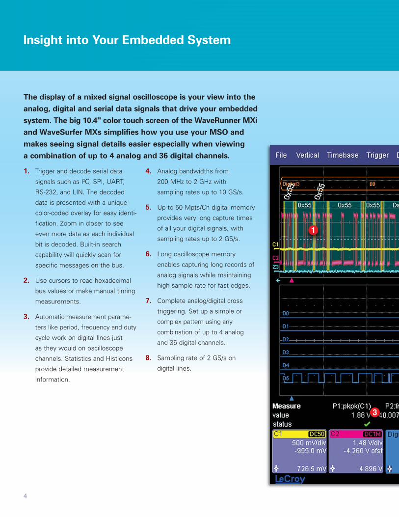
1. Trigger and decode serial data
signals such as I2C, SPI, UART,
RS-232, and LIN. The decoded
data is presented with a unique
color-coded overlay for easy identi-
fication. Zoom in closer to see
even more data as each individual
bit is decoded. Built-in search
capability will quickly scan for
specific messages on the bus.
2. Use cursors to read hexadecimal
bus values or make manual timing
measurements.
3. Automatic measurement parame-
ters like period, frequency and duty
cycle work on digital lines just
as they would on oscilloscope
channels. Statistics and Histicons
provide detailed measurement
information.
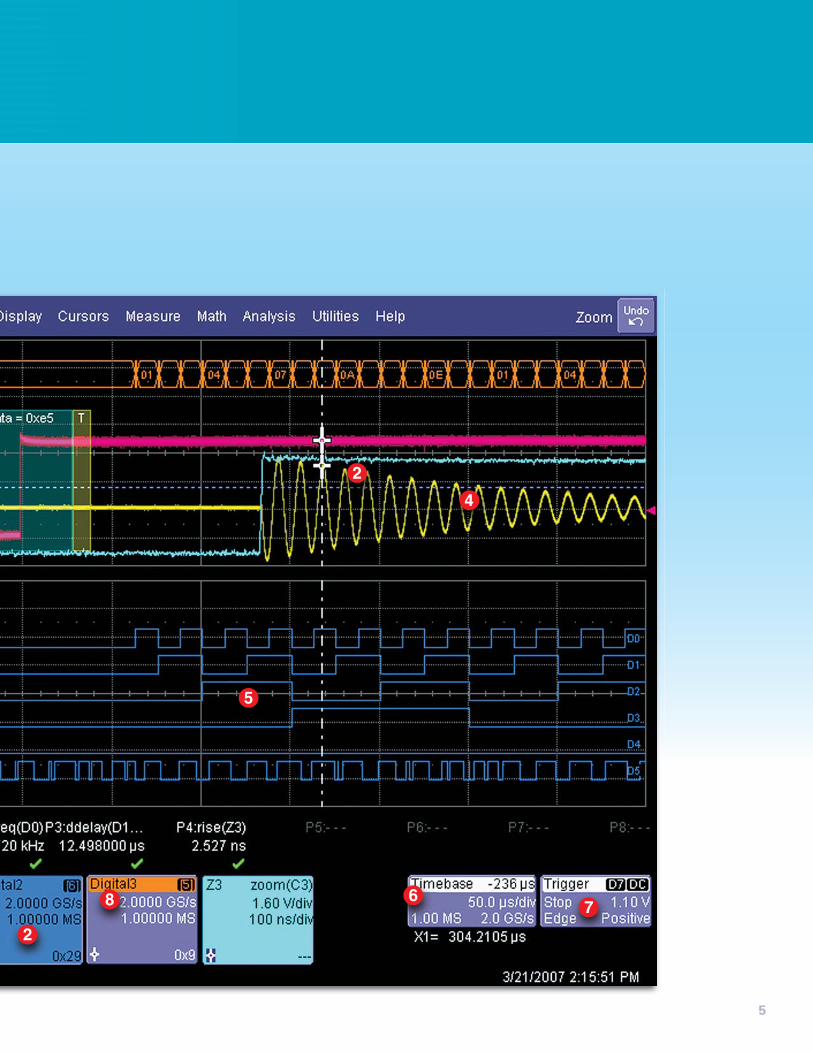
4. Analog bandwidths from
200 MHz to 2 GHz with
sampling rates up to 10 GS/s.
5. Up to 50 Mpts/Ch digital memory
provides very long capture times
of all your digital signals, with
sampling rates up to 2 GS/s.
6. Long oscilloscope memory
enables capturing long records of
analog signals while maintaining
high sample rate for fast edges.
7. Complete analog/digital cross
triggering. Set up a simple or
complex pattern using any
combination of up to 4 analog
and 36 digital channels.
8. Sampling rate of 2 GS/s on
digital lines.
5
5
8
2
2
4
67
Serial Data Bus Validation and Debug
6
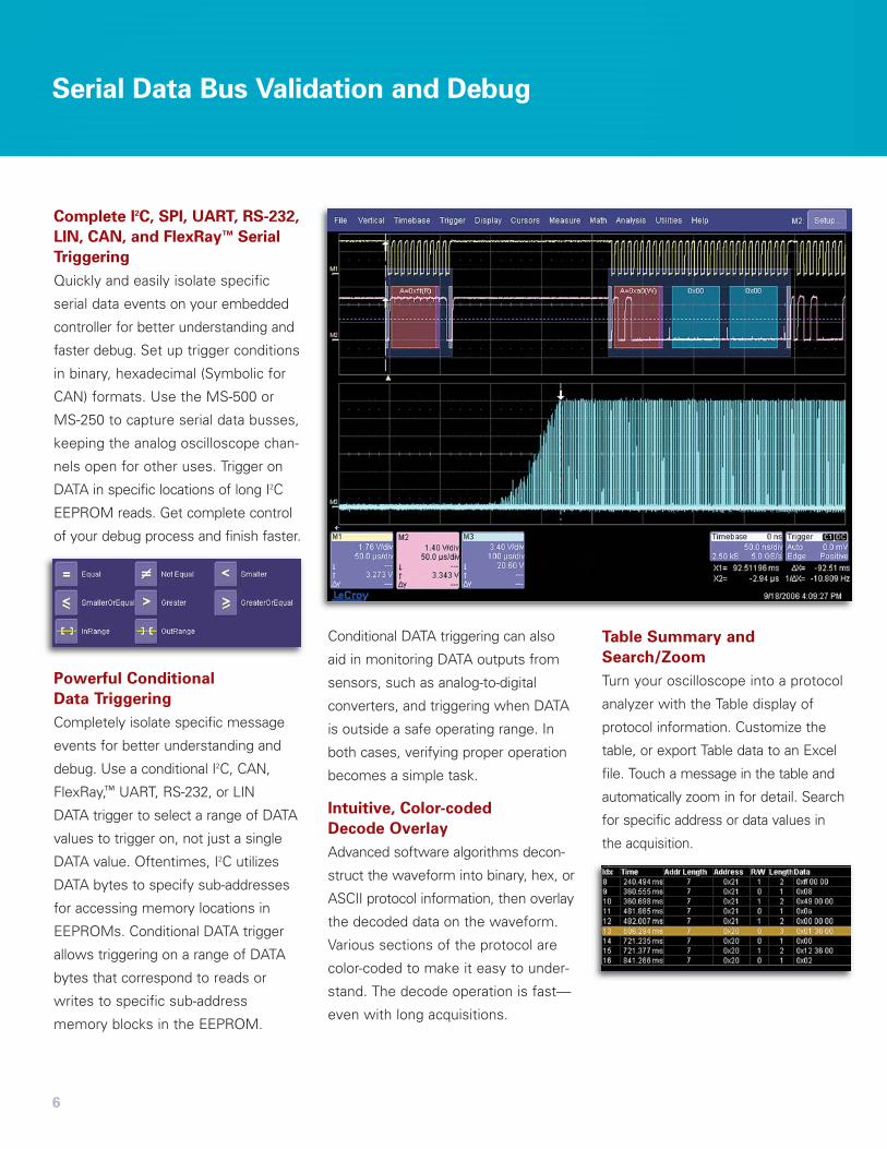
Complete I2C, SPI, UART, RS-232,
LIN, CAN, and FlexRay™ Serial
Triggering
Quickly and easily isolate specific
serial data events on your embedded
controller for better understanding and
faster debug. Set up trigger conditions
in binary, hexadecimal (Symbolic for
CAN) formats. Use the MS-500 or
MS-250 to capture serial data busses,
keeping the analog oscilloscope chan-
nels open for other uses. Trigger on
DATA in specific locations of long I2C
EEPROM reads. Get complete control
of your debug process and finish faster.
Powerful Conditional
Data Triggering
Completely isolate specific message
events for better understanding and
debug. Use a conditional I2C, CAN,
FlexRay,™ UART, RS-232, or LIN
DATA trigger to select a range of DATA
values to trigger on, not just a single
DATA value. Oftentimes, I2C utilizes
DATA bytes to specify sub-addresses
for accessing memory locations in
EEPROMs. Conditional DATA trigger
allows triggering on a range of DATA
bytes that correspond to reads or
writes to specific sub-address
memory blocks in the EEPROM.
Conditional DATA triggering can also
aid in monitoring DATA outputs from
sensors, such as analog-to-digital
converters, and triggering when DATA
is outside a safe operating range. In
both cases, verifying proper operation
becomes a simple task.
Intuitive, Color-coded
Decode Overlay
Advanced software algorithms decon-
struct the waveform into binary, hex, or
ASCII protocol information, then overlay
the decoded data on the waveform.
Various sections of the protocol are
color-coded to make it easy to under-
stand. The decode operation is fast—
even with long acquisitions.
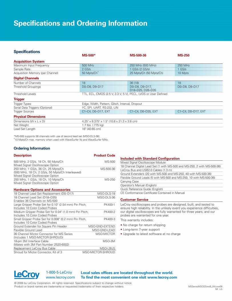
Table Summary and
Search/Zoom
Turn your oscilloscope into a protocol
analyzer with the Table display of
protocol information. Customize the
table, or export Table data to an Excel
file. Touch a message in the table and
automatically zoom in for detail. Search
for specific address or data values in
the acquisition.
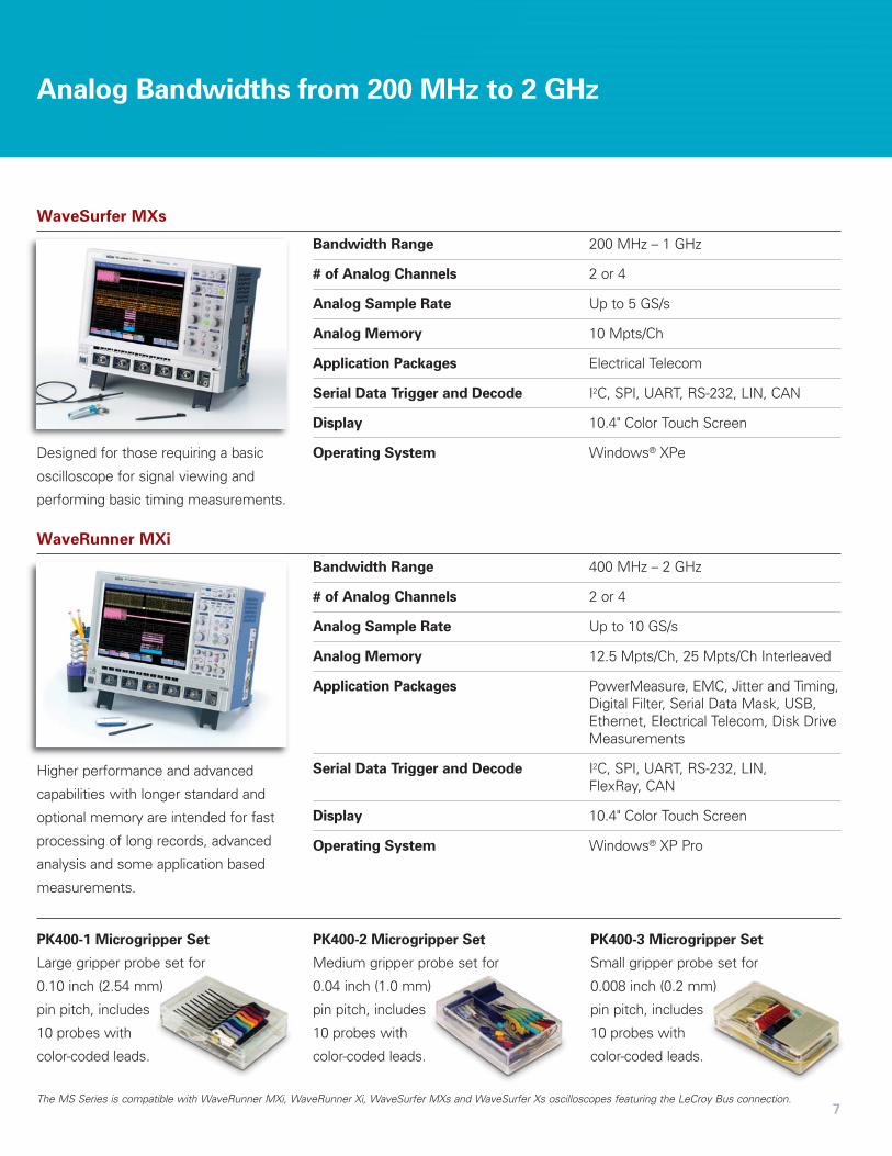
WaveRunner MXi
Higher performance and advanced
capabilities with longer standard and
optional memory are intended for fast
processing of long records, advanced
analysis and some application based
measurements.
7
Analog Bandwidths from 200 MHz to 2 GHz
WaveSurfer MXs
Designed for those requiring a basic
oscilloscope for signal viewing and
performing basic timing measurements.
Bandwidth Range 200 MHz – 1 GHz
# of Analog Channels 2 or 4
Analog Sample Rate Up to 5 GS/s
Analog Memory 10 Mpts/Ch
Application Packages Electrical Telecom
Serial Data Trigger and Decode I2C, SPI, UART, RS-232, LIN, CAN
Display 10.4" Color Touch Screen
Operating System Windows® XPe
Bandwidth Range 400 MHz – 2 GHz
# of Analog Channels 2 or 4
Analog Sample Rate Up to 10 GS/s
Analog Memory 12.5 Mpts/Ch, 25 Mpts/Ch Interleaved
Application Packages PowerMeasure, EMC, Jitter and Timing,Digital Filter, Serial Data Mask, USB,Ethernet, Electrical Telecom, Disk DriveMeasurements
Serial Data Trigger and Decode I2C, SPI, UART, RS-232, LIN, FlexRay, CAN
Display 10.4" Color Touch Screen
Operating System Windows® XP Pro
PK400-2 Microgripper Set
Medium gripper probe set for
0.04 inch (1.0 mm)
pin pitch, includes
10 probes with
color-coded leads.
PK400-3 Microgripper Set
Small gripper probe set for
0.008 inch (0.2 mm)
pin pitch, includes
10 probes with
color-coded leads.
The MS Series is compatible with WaveRunner MXi, WaveRunner Xi, WaveSurfer MXs and WaveSurfer Xs oscilloscopes featuring the LeCroy Bus connection.
PK400-1 Microgripper Set
Large gripper probe set for
0.10 inch (2.54 mm)
pin pitch, includes
10 probes with
color-coded leads.
Specifications and Ordering Information
MSSeriesMSODSrevB_04June085K LG
MS-500* MS-500-36 MS-250
Acquisition SystemMaximum Input Frequency 500 MHz 250 MHz (500 MHz) 250 MHzSample Rate 2 GS/s 1 GS/s (2 GS/s) 1 GS/sAcquisition Memory (per Channel) 50 Mpts/Ch† 25 Mpts/Ch (50 Mpts/Ch) 10 Mpts
Digital Channels
Number of Channels 18 36 (18) 18Threshold Groupings D0–D8, D9–D17 D0–D8, D9–D17, D0–D8, D9–D17
D18–D25, D26–D35Threshold Levels TTL, ECL, CMOS (2.5 V, 3.3 V, 5 V), PECL, LVDS or User Defined
Trigger
Trigger Types Edge, Width, Pattern, Glitch, Interval, DropoutSerial Data Triggers (Optional) I2C, SPI, UART, RS-232, LINTrigger Sources C1–C4, D0–D17, EXT C1–C4, D0–D35, EXT C1–C4, D0–D17, EXT
Physical Dimensions
Dimensions (W x L x D) 4.25" x 8.375" x 1.5" (10.8 x 21.3 x 3.8 cm)Net Weight 1.7 lbs. (.775 kg)Lead Set Length 16" (40.65 cm)
*MS-500 supports 36 channels with use of second lead set (MSO-DLS-36).†10 Mpts/Ch max. memory when used with WaveSurfer Xs and WaveSurfer MXs.
Ordering Information
Specifications
Description Product Code
500 MHz, 2 GS/s, 18 Ch, 50 Mpts/Ch MS-500Mixed Signal Oscilloscope Option250 MHz, 1 GS/s, 36 Ch, 25 Mpts/Ch MS-500-36(500 MHz, 18 Ch, 2 GS/s, 50 Mpts/Ch Interleaved) Mixed Signal Oscilloscope Option250 MHz, 1 GS/s, 18 Ch, 10 Mpts/Ch MS-250Mixed Signal Oscilloscope Option
Hardware Options and Accessories18 Channel Lead Set Replacement (D0–D17) MSO-DLS-1818 Channel Lead Set (D18–D35) MSO-DLS-36Enables 36 Channels on MS-500Large Gripper Probe Set for 0.10" (2.54 mm) Pin Pitch, PK400-1Includes 10 Color Coded ProbesMedium Gripper Probe Set for 0.04" (1.0 mm) Pin Pitch, PK400-2Includes 10 Color Coded ProbesSmall Gripper Probe Set for 0.008" (0.2 mm) Pin Pitch, PK400-3Includes 10 Color Coded ProbesGround Extender for Square Pin Header MSO-GND-EXTENDFlexible Ground Lead MSO-GND-LEAD36 Channel Mictor Connector for MS Series MSO-MICTOR(Includes 1 MSO-MICTOR-SHROUD)18-pin 3M Interface Cable MSO-3M(Mates with 3M Part Number 2520-6002)Replacement LeCroy Bus Cable MSO-LBUSShroud for Mictor Connector, Kit of 3 MSO-MICTOR-SHROUD
Included with Standard ConfigurationMixed Signal Oscilloscope Module18 Channel Digital Lead Set (1 with MS-500 and MS-250, 2 with MS-500-36)LeCroy Bus and USB2.0 Cables (1.3 m)Ground Extenders (20 with MS-500 and MS-250, 40 with MS-500-36)Flexible Ground Leads (5 with MS-500 and MS-250, 10 with MS-500-36)Carrying CaseOperator’s Manual (English)Quick Reference Guide (English)CE Conformance Certificate Contained in Manual
Customer Service
LeCroy oscilloscopes and probes are designed, built, and tested toensure high reliability. In the unlikely event you experience difficulties,our digital oscilloscopes are fully warranted for three years, and ourprobes are warranted for one year.This warranty includes:
• No charge for return shipping • Long-term 7-year support • Upgrade to latest software at no charge
© 2008 by LeCroy Corporation. All rights reserved. Specifications subject to change without notice.Product or brand names are trademarks or requested trademarks of their respective holders.
1-800-5-LeCroywww.lecroy.com
Local sales offices are located throughout the world.
To find the most convenient one visit www.lecroy.com