Embed Size (px)
Citation preview

D R . T A R E K A . T U T U N J I
P H I L A D E L P H I A U N I V E R S I T Y , J O R D A N
2 0 1 4
MSD: Case Studies

Outline
Elements and design of mechatronic systems have been described in previous sections
This section presents the design process of two mechatronic systems
Liquid Level Control
CNC Machine
Liquid Level Control

Liquid Level Control
Liquid level control systems are commonly used in many process control applications to control, for example, the level of liquid in a tank.
Liquid enters the tank using a pump, and after some processing within the tank the liquid leaves from the bottom of the tank.
The requirement in this system is to control the rate of liquid delivered by the pump so that the level of liquid within the tank is at the desired point

Specifications
Tank size is 1m x 2m x 1m
Desired level between 0.8 to 1.2 meters
Settling time < 20 min
Rise time < 2 min
Plant Flow Rate Height Level
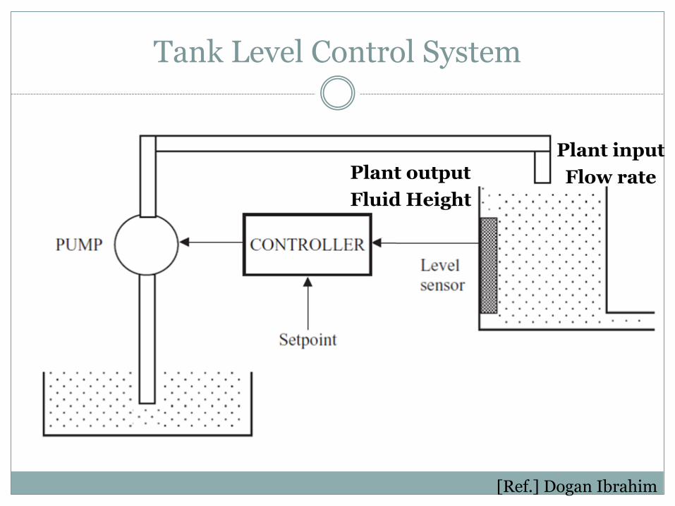
Tank Level Control System
[Ref.] Dogan Ibrahim
Plant output
Fluid Height
Plant input
Flow rate

System Model
Note that the plant has a first order model
v1(t) is the input flow rate v2(t) is the output flow rate h is the height A is the surface area R is the outlet pipe resistance

Open Loop Simulation
Assume the following values
Qin = 10 liter/min (1.66e-4 m3/ sec)
A = 2 m2
TF = 15 / (30 s + 1)
Desired height is 1 meter

Open Loop
>> num=15; den=[30 1]; >> sys=tf(num,den); >> step(sys)
Step Response
Time (sec)
Am
plit
ude
0 20 40 60 80 100 120 140 160 1800
5
10
15
System: sys
Settling Time (sec): 117
Note again that there is no overshoot because the model is first order

Closed Loop
>> sysCL=feedback(sys,1); >> step(sysCL) Step Response
Time (sec)
Am
plit
ude
0 2 4 6 8 10 120
0.1
0.2
0.3
0.4
0.5
0.6
0.7
0.8
0.9
1
System: sysCL
Settling Time (sec): 7.34

Sensors Choice
Controller Comment
Ultrasonic Needs added circuitry
Potentiometer with float Works well
Electrodes Works
Resistance probes Discrete applications
Photo sensors Discrete applications Also, might not work with water

12-Volt Water Pump
Assume 20 PSI conditions 12volts provides 2 GPM

Power Op-Amp

Controller Choice
Controller Comment
Microcontroller Works well
PLC Too expensive Not usually used for SISO
DSP Too complex Not enough inputs to justify No need for fast response to justify
FPGA Too complex No need for fast response
PC with DAQ Too expensive No need to visual graphics
Electronics Only Works well, but difficult to modify

Schematic Diagram
[Ref.] Dogan Ibrahim

Components
Water pump
12V water pump drawing about 3A when operating at the full-scale voltage.
Level sensor.
A rotary potentiometer type level sensor with a floating. The level of the floating arm, and hence the resistance, changes as the liquid level inside the tank is changed. The resistance changes from 430 to 40 Ohm
Components
Microcontroller A PIC16F877 type microcontroller is used in this project as the
digital controller. In general, any other type of microcontroller with a built-in A/D converter can be used.
D/A converter An 8-bit AD7302 type D/A converter is used in this project.
Power amplifier An LM675 type power (30W of power) amplifier is used to increase
the power output of the D/A converter and drive the pump.

System Model

System Block Diagram
[Ref.] Dogan Ibrahim

Hardware Set-up
[Ref.] Dogan Ibrahim

Computer Numerical Control
CNC Machine
Computer Numerical Control (CNC) system
Specifications: Speed
Accuracy
Working material
Power and Torque
Work area size
CNC machine size
User Interface
Cost

CNC Block Diagram
[Ref.] Saluki Engineering Company

CNC Machine
• Motors for positioning • Motor for drilling

CNC Machine: Positioning Actuator Options
[Ref] Goodfry
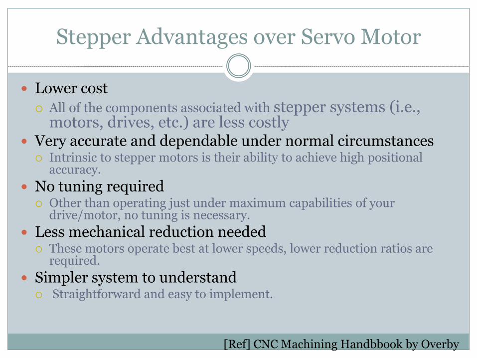
Stepper Advantages over Servo Motor
Lower cost
All of the components associated with stepper systems (i.e., motors, drives, etc.) are less costly
Very accurate and dependable under normal circumstances Intrinsic to stepper motors is their ability to achieve high positional
accuracy.
No tuning required Other than operating just under maximum capabilities of your
drive/motor, no tuning is necessary.
Less mechanical reduction needed These motors operate best at lower speeds, lower reduction ratios are
required.
Simpler system to understand Straightforward and easy to implement.
[Ref] CNC Machining Handbbook by Overby

Motor Torque Calculations
Determine the motion profile and calculate acceleration, deceleration and maximum velocity required to make the desired move.
Select mechanical drive mechanism to be used and
calculated inertia, friction and load torque. Determine required motor torque for the specific
application. Select proper motor and driver based on their speed-
torque characteristics
[Ref.] www.t2cnc.hu
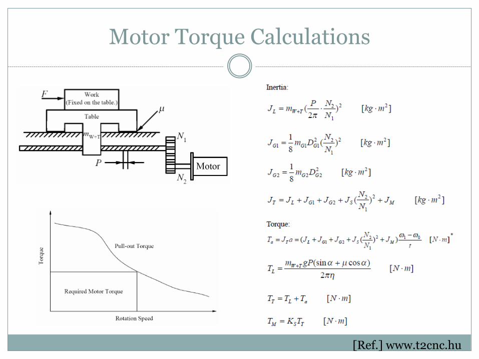
Motor Torque Calculations
[Ref.] www.t2cnc.hu
Selecting Stepper Motor
Calculate the total torque needed at the output shaft of the motor.
Use the motor performance curve to select a motor with at least 50% more torque than that calculated at the required maximum Speed.
Select a driver that is capable of supplying the needed current to the motor of choice and providing the resolution needed.

NEMA34 Stepper Motor

Stepper Motor Torque-Speed Curves

Stepper Motors

Speed Profile

Stepper Motor Driver
Cytron Tech SD02B
CNC Machine Specs Design
The controller coordinates all the system actions. Its output is connected to an interface card that sends signals to the stepper motors.
The stepper motors carry the worktable on which the
work-piece is supported. Load on steppers is 30 N Torque of 1.75 N.m (250 oz-in)
Two stepper motors are required to provide movement,
one in the x-direction and one in the y-direction. The stepper motors are synchronous 1.8° motors giving a half step
angle of 0.9° per revolution.

Conclusion
Mechatronics Design follows well-defined iterative steps that include synergistic design.
It is composed of three stages: 1. Define the Objective and Specifications Includes customer needs and engineering specs
2. Analyze and Design Understand I/O to select appropriate sensors and actuators Choose controller algorithm and hardware Model and Simulate
3. Build and Test Build prototype and measure performance according to specs