Embed Size (px)
Citation preview
8/8/2019 MSFC Skylab Crew Systems Mission Evaluation
http://slidepdf.com/reader/full/msfc-skylab-crew-systems-mission-evaluation 1/397
NASA TECHNICAL
MEMORANDUM
NASA TM X-64825
N74- 32316August 1974
\
MSFC SKYLAB CREWSYSTEMSMISSION EVALUATION
Skytab Program Office
NASA
. ,//?_-3 2.3/o,,o (ACCESSION NUMBER) (THRU)
O (PAGES) (CODE)
(NASA CR OI:_T/_,X OR AD NUMBER) (CATEGORY)
/-/c "_-2 E"
George C.Marshall
Marshall Space Flight Center
Space Flight Center, Alabama
MSFC - Form 3190 (Rev J'une 1971)
• .,/.
i_,::i i:i ¸ i_:¸'- _

8/8/2019 MSFC Skylab Crew Systems Mission Evaluation
http://slidepdf.com/reader/full/msfc-skylab-crew-systems-mission-evaluation 2/397
8/8/2019 MSFC Skylab Crew Systems Mission Evaluation
http://slidepdf.com/reader/full/msfc-skylab-crew-systems-mission-evaluation 3/397
Errata TMX-64825 Section IV Pages 192 - 212 10/15/74
O
O
Page 192, fifth paragraph, first sentence should read as follows:
"Experiments S019, S073/T027, S149, T025, T027, S183, $201 and a TV I'
Page 196, paragraph 3. Substitute the term "detector package" for"... door on the experiment housing . " in the first sentence, and for"... experiment door ..." in the third sentence.
Page 200 delete the last sentence of the sixth paragraph and substitute with:
The experiment hardware and procedures were adequate and the experiment
operations were acomplished with only minor anomalies; one triple exposure,
and one of the filters became contaminated causing loss of data.
Page 203 delete paragraph two and substitute with:
Due to solar SAL obstructions by the thermal shield, the S019 AMS
was utilized to obtain some of the S063 data, resulting in a much smaller
FOVo This required that an adapter be flown up on the SL-3 to accomodate
S063 on the SMS.
Page 205 delete heading numbered 5. and substitute with:
5. S073/T027 - Gerenschein/Zodiacal Light and Contamination Measurement-
Photometer System
Page 205 delete the first sentence in Paragraph one of sub heading 5a.Operations and substitute with:
The experiment S073/T027 Photometer System was scheduled for operationduring SL-2, SL-3 and SL-4.
Page 206 delete partial paragraph at top of page and substitute with:
o•. was moved out of the camera's view. The T025 Canister was mounted to
the S019 AMS using the S063 adapter• No anomalies were reported. However,all SL-4 photographs were out of focus, apparently due to a missing pres-
sure plate in the Nikon 02 camera•
Page 209 delete line one of the second complete paragraph_and substitutewith:
The crew also experienced a jamming problem with the DAC film magazine
which caused the entire spectrograph to cease functioning.
Page 210 add this sentence as written to the end of the last paragraph:
One of the harness dector modules was left in the MDA for retrieval shoulda revisit to the Skylab ever be made.
Page 212 add this sentence as written to the end of the last paragraph.
However, all the photographs were taken at the wrong focus setting, re-suiting in out-of-focus pictures•

8/8/2019 MSFC Skylab Crew Systems Mission Evaluation
http://slidepdf.com/reader/full/msfc-skylab-crew-systems-mission-evaluation 4/397
!!!!ii,'! ', !
8/8/2019 MSFC Skylab Crew Systems Mission Evaluation
http://slidepdf.com/reader/full/msfc-skylab-crew-systems-mission-evaluation 5/397
Errata TMX-64825 Section IV pages 214 - 221 10/15/74
O
O
O
O
O
O
O
Page 214, first paragraph, second sentence, should read:
"The equipment for the D024, consisting of two thermal control coated
samples, two polymeric film sample panels, and two return containers..."
Page 214 delete heading marked "2." written in correct form as:
2. M512 (M551_ M552_ M553, M555) Material Processing in Space
M479 Zero Gravity Flammobality M518 _556-M566) MultipurposeElectric Furnance
Page 216 delete the words (and surface tension) from the end of sentence
one, paragraph one, and add the following phrase to the end of the sentence:
"_.. and material science investigation in the areas of crystal growth,immiscibles, composites, diffusion, and eutectics."
Delete the last sentence of the first paragraph and substitute with:Experiments M551-M553, M555, M556-M566 and M479 utilized the M512facilities.
Page 217 add a paragraph between paragraph six and seven, correctly written:Angles between various celestial targets were to be observed, and the
mean error and standard deviation between successive readings in a group
were to be used as a measure of any change in the crewman's ability, to
make decisions and measurements as caused by the space environment.
Page 217 delete from paragraph seve_ line two "... all three ..."place with, "... the last two ..."
, re-
Page 217 add a sentence to the last paragraph, correctly written:
During SL-4, the transparent wardroom window cover was left in place forall but the last two groups of sightings. The mean error and the standard
deviation were large when the cover was in place.
Page 219, second paragraph, after the last sentence add the following:
"Also, the upper atmosphere of the earth was to be photographed."
Page 220, first paragraph, first sentence, delete: "... and Zodiacal light..."
Page 220, first paragraph, lines 5, 6, 7 substitute the work "Nikon" forthe word, "DAC".
Page 220, second paragraph, first sentence should read as follows:
As an alternate method .... truss, and a new occulting disc were design-ed and launched on SL-3.
Page 221, first paragraph, first sentence should read as follows:The T025 experiment was performed from the anti-solar SAL on SL-3 and
SL-4, and with the S019 AMS on SL-4 with only minor problems.

8/8/2019 MSFC Skylab Crew Systems Mission Evaluation
http://slidepdf.com/reader/full/msfc-skylab-crew-systems-mission-evaluation 6/397
8/8/2019 MSFC Skylab Crew Systems Mission Evaluation
http://slidepdf.com/reader/full/msfc-skylab-crew-systems-mission-evaluation 7/397
__
::/
o
o
o
o
o
o
o
o
Errata TMX-64825 Section IV pages 22i i- 232 10/15/74
Page 221, second paragraph should read as follows:
T025 was not originally designed for EVA use but, with the addition of
the specially designed EVA bracket, occulting disc assembly and filters
(illustrated in section VI, E), ultraviolet photographs ware taken of the
earth's upper atmosphere
Page 221, add a paragraph following the last paragraph as follows:
Upon return to earth, it was learned that the carrousels had not
apparently rotated wither due to the failure of the crewman to initiate
the power to the experiment or due to the extreme low temperature at
the anti-solar SAL for which the experiment was not designed.
Page 224, fifth paragraph, third sentence should read as follows:
To reduce/eliminate .... the LSU of its wiring and insulation, leaving
only the 02 line.
Page 227, second paragraph, prior to first sentence add:
"The Skylab crews suggested that ..."
Page 228 delete last sentence of seventh paragraph i.e. "The FMU's were
placed..."
Page 228, eighth paragraph, first sentence, delete, "... adjacent to the
film vault..."
Page 228, last paragraph, third line, third word change from "five" to "two"
Page 228 delete last sentence of the last paragraph and rewrite as follows:
Of the two performaces conducted, one shirt sleeve and one suited run was
planned for each of the SL-3 and SL-4 missions.
Page 229 delete second paragraph and rewrite as follows:
b. Post Mission Assessment-Experiment T020 was performed as planned
on SL-3 with the test pilot operating the FCMU three times. The first
two runs were performed in shirtsleeve while the last was flown suited.
The suited run was conducted utilizing both the Life Support Umbilical
(LSU) and Secondary Oxygen Pack (SOP) configurations. On SL-4, TO20 was
performed twice; both in shirtsleeves.
Page 231, third paragraph, first sentence should read as follows:
"The first SL-4, T020 run was performed in shirtsleeves..."
Page 231, first paragraph, second sentence shoudl read as follows:
Using a:sca_ipel_...stripped of wiring and insulation, leaving only the02 line.
Page 232 add a sentence to the end of the first paragraph as follows:
An additional data pass was made on SL-3.
Page 232, second paragraph, second sentence, add to the end of the sentence
the following: "...during the dark cycle of the moon."

8/8/2019 MSFC Skylab Crew Systems Mission Evaluation
http://slidepdf.com/reader/full/msfc-skylab-crew-systems-mission-evaluation 8/397
• _ • _ • •_ i___ _•_ _i_iii_!i_i_ i_ _i_i_ • '_'_, _i _ ,_ii_,__,_, _ _ _ •
8/8/2019 MSFC Skylab Crew Systems Mission Evaluation
http://slidepdf.com/reader/full/msfc-skylab-crew-systems-mission-evaluation 9/397
Errata TMX-64825 Section IV pages 232 - 241 10/15/74
o Page 232, paragraph four, line two, delete second work "SL-3" andreplace with "SL-4".
o Page 232, paragraph 2b., rewrite as follows:
b. Post Mission Assessment - Student experiment ED25 was not performed
due to the failure of one CMG.
o Page 233 delete first word, line two of first paragraph, "SL-3" and
substitute with, "SL-2".
o Page 233, paragraph 4b, first sentence, rewrite to read as follows:
"b, Post Mission Assessment - Due to ... was rescheduled for a
second performance on SL-4"o Delete the fourth and fifth sentences.
o Page 233, paragraph 5b, second sentence, replace "Ten days..." with"Twenty-three hours..,"
o Page 234 change the third sentence of third paragraph to read as follows:
The experiment was performed early-, mid-, and late-mission by all threec r ewme n °
o Page 236, paragraph 8a, first sentence, change "SL-2"to "SL-4".
o Page 236 delete paragraph 8b amd substitute with the following paragraph:
b. Post Mission Assement Due to the high OWS temperatures afterlaunch, and subsequent on-ground testing, it was determined that the
seed germination probability had been significantly reduced. Resupplyof seeds was carried out on SL-3 and performance of ED 61/62 was accom-
plished during SL-4. The seeds were implanted and photographed asscheduled with no anomalies reported.
o Page 239 delete the last two sentences on page.
o Page 240 delete the third paragraph.
o Page 240, paragraph lla, second sentence, substitute "behind" for "in".
o Page 240 delete the last sentence of the fifth paragraph, i.e. "Next,the mass..."
o Page 241, third line, add the following sentence:
An additional dector was launched on SL-4.

8/8/2019 MSFC Skylab Crew Systems Mission Evaluation
http://slidepdf.com/reader/full/msfc-skylab-crew-systems-mission-evaluation 10/397
_ i_I_i_i_i_i!_i_!il,_!_ '!_ _iI,__i_ki it _¸ •k __!!i!_i_! ii_!_i_i_I i_i̧ ¸__ ._ i .k
8/8/2019 MSFC Skylab Crew Systems Mission Evaluation
http://slidepdf.com/reader/full/msfc-skylab-crew-systems-mission-evaluation 11/397
TECHNICAt
t. REPORT NO. 12 GOVERNMENT ACCESSION NO.
NASA TM X-64825 I4. TITLE AND SUBTITLE
MSFC SKYLAB CREW SYSTEMS MISSION EVALUATION
7. AUTHOR(S)
SYSTEM ANALYSIS & INTEGRATION LABORATORY
9. PERFORMINGORGANIZATIONNAME AND ADDRESS
George C. Marshall Space Flight Center
Marshall, Space Flight Center, Alabama.. _ 35812
12. SPONSORINGAGENCYNAME AND ADDRESS
National Aeronautics and Space Administration
Washington, D.C. 20546
REPORT STANDARD TITLE
3. RECIPIENT'S CATALOG NO.
5, REPORT DATE
August 19746. PERFORMING ORGANIZATION C
8, PERFORMING ORGANIZATION REP
10. WORK UNIT NO.
I. CONTRACT OR GRANT NO.
13, TYPE OF REPORt," & PERIOD COV
Technical Memorandum
14. SPONSORING AGENCY CODE
15. SUPPLEMENTARY NOTES
16, ABSTRACT
THIS REPORT PRESENTS A CONCISE PERFORMANCE EVALUATION OF MSFC RESPONSABLE SKYLAB
CREW SYSTEM HARDWARE. THE GEORGE C. MARSHALL SPACE FLIGHT CENTER HAD
PRIMARY HARDWARE DEVELOPMENT AND SYSTEM INTEGRATION RESPONSABILITIES FOR THE
SKYLAB ORBITAL CLUSTER MODULES EXCLUSIVE OF THE COMMAND AND SERVICE MODULE AND
INCLUDING MANY OF THE DESIGNATED EXPERIMENTS. THIS REPORT ALSO INCLUDES
HARDWARE DESIGN DESCEIPTIONS, POST-MISSION ASSESSMENTS, AND HARDWARE DESIGN
RECOMMENDATIONS WITH POTENTIAL APPLICATION TO FUTURE PROGRAMS.
17. KEY WORDS
19. SECURITY CLASSIF, (of thil teport_ 720.
Jnclassified
MSFC - Form _ 292 (Rev December [ 972)
18. DISTRIBUTION STATEMENT
Unclassified-unli mited
SECURITY CLASSIF. (of this page) ]21. NO. OF PAGES 22. PRICE
Unclassified .__ 384 NTIS
For _ale by National Technical Inform_ lion _ er vtc e, Spri ng fie ld, Virginia 221

8/8/2019 MSFC Skylab Crew Systems Mission Evaluation
http://slidepdf.com/reader/full/msfc-skylab-crew-systems-mission-evaluation 12/397
8/8/2019 MSFC Skylab Crew Systems Mission Evaluation
http://slidepdf.com/reader/full/msfc-skylab-crew-systems-mission-evaluation 13/397
p_ECEDLMG pAGE BLANK NOT FILI_EO
TABLE OF CONTENTS
TABLE OF CONTENTS .....................LIST OF ILLUSTRATIONS] ....................
LIST OF TABLES .......................
INTRODUCTION ..... .. .. .. .. .. .. .. .. .. .
SECTION I. SKYLAB CONFIGURATION EVOLUTION -
A PERSPECTIVE VIEW ...............
A. Multiple Docking Adapter (MDA) ...........B. Airlock Module (AM) and Structural Transition
Section (STS) ................C. Orbital Workshop (;W;)] ..............
SECTION II. HABITABILITY, ARCHITECTURAL, ANDCREW PROVISIONS ................
A. Water System ............
i. Water Stor;g;, Treatment_ and Distributi;n] . .
B. Waste Management System ..............
i. Fecal Collection ................
2. Urine Collection ................
3. Waste Processor ................
4. Urine Freezer .................
5. Suit Drying ..................
C. Personal Hygiene Provisions ............
i. Handwasher ...................
2. Shower .....................
3. Hygiene Equipment ...............
D. Sleep Provisions ..................
i. Sleep Restraints ................
2. Privacy Curtains ................
3. Light Baffles .................
E. Food Management System ...............
i. Food Galley/Pantry ...............
2. Food Table Equipment ..............
3. Food Storage Containers ..........
4. Food Freezers and Chillers] ..........
5. Transfer and Resupply .............
F. Housekeeping ....... . ............i. Trash Collection ................
2. Vacuum Cleaner .................
3. Microbial Control ...............
G. Trash Disposal ...................
I. Trash Airlock (TAL) ..............
Page
°.°
Ill
viii
xiii
i
2
2
3
3
6
6
25
25
3O
3845
47
49
49
51
53
59
59
62
63
65
65
68
73
75
80
8181
84
85
88
88
iii
8/8/2019 MSFC Skylab Crew Systems Mission Evaluation
http://slidepdf.com/reader/full/msfc-skylab-crew-systems-mission-evaluation 14/397
TABLE OF CONTENTS (Continued)
H. Debris Control ...................
i. Design Description ...............2. Post Mission Assessment. ...........
I. Hatches ......................
i. OWS Access Hatch ................
2. MDA Hatches ..................
3. AM Hatches ...................
J. Crew Stations ...................
i. MDA Crew Station ............... .
2. AM Crew Station ................
3. OWS Crew Station ................
K Mobility-Stability Aids
i. Design Description ...............2. Post Mission Assessment ............
L. Stowage ......................
i. Containers ...................2. Internal Arrangement ..............
3. Equipment Restraints ..............
4. Fasteners . . . . . . . . . . . . . . . . . . .
5. Placards and Labels ..............
6. Transfer Stowage ................
7. Consumable Summary ...............
M. Illumination ....................
i. Fixed Illumination ...............
2. Portable Illumination .............
N. Crew Communications ................
i. Audio System ..................2. Vocal (Unaided) Communication .........
SECTION III. CONTROLS AND DISPLAYS .............
A. Orbital Workshop ..................
I. Design Description ...............
2. Post Mission Assessment ............
B. Airlock Module ...................
i. Design Description ...............2. Post Mission Assessment ............
C. Apollo Telescope Mount ...............
i. Design Description ...............
2. Experiment Interface Evaluation ........
3. System Interface Evaluation ..........4. Design Solutions and Recommendations ......
5. Results of SL-2 Telemetry Data Analysis ....
6. Summary and Conclusions ............
APPENDIX A CREW DEBRIEFING. . o ............
Pa e
96
96
96
98
98
98i00
103
103
107
iii
118
118
126
134
134137
137
138
150
152
152
159
159
162
164
164
167
168
168
168
168
170
170
171
175
175
175
181184
184
187
189
iv
8/8/2019 MSFC Skylab Crew Systems Mission Evaluation
http://slidepdf.com/reader/full/msfc-skylab-crew-systems-mission-evaluation 15/397
SECTIONV.
A.B.
C.
Do
Eo
F.
.
7.
8.
9.
i0.
ii.
12.
TABLE OF CONTENTS (Continued)
Page
Do
6.
7.
8.
9.
i0.
ii.
12.
13.
Corollary Experiments Summary ........... 191Scientific Airlock System ............. 192i. Scientific Airlock ............... 192
Scientific Experiments ............... 196i. S009 - Nuclear Emulsion ............ 196
2. S019 - UV Stellar Astronomy .......... 196
3. S020 - UV X-Ray Solar Photography ....... 200
4. S063 - UV Airglow Horizon Photography ..... 2005. S073/T027 - Gegenschein Zodiacal Light and
ATM Contamination Measurement ......... 205
S149 - Particle Collection ........... 206
S183 - Ultraviolet Panorama .......... 208
$201 - Electron.graphic Camera ......... 210
$228 - Trans-Uranic Cosmic Rays ........ 210
$230 - Magnet.spheric Particle Composition. . . 211$232 - Barium Plasma Observations ....... 212
$233K - Kohoutek Photometric Photography .... 213
Technology Experiments ............... 214
i. D024 - Thermal Control Coatings ........ 214
2. M512 (M551, M542, M553, M555) -
Materials Processing in Space M479 - Zero
Gravity Flammability - M518 - Multipurpose
Electric Furnace System ............ 214
3. T002 - Manual Navigation Sightings ....... 217
4. T003 - In-Flight Aerosal Analysis ....... 218
5. T025 - Coronagraph Contamination Measurement.. 2196. T027 - Sample Array .............. 221
Operations Experiments ............... 223
i. M487 - Habitability/Crew Quarters ....... 223
2. M509 - Astronaut Maneuvering Equipment ..... 223
3. TOI3 - Crew/Vehicle Disturbances ........ 227
4. T020 - Foot Controled Maneuvering Unit ..... 228
Student Project Experiments ............ 232
i. ED23 - Ultraviolet From Quasars ........ 232
2. ED25 - X-Rays From Jupiter ........... 232
3. ED26 - Ultraviolet From Pulsars ........ 232
4. ED31 - Bacteria and Spares ........... 233
ED32 - Invitro Immunology ........... 233
ED41 - Motor Sensory Performance ........ 234
ED52 - Web Formation .............. 234
ED61/62 - Plant Growth/Plant Phototropism . . . 236ED63 - Cytoplasmic Streaming .......... 236
ED72 - Capillary Study ............. 239ED74 - Mass Measurement ............ 240
ED76 - Neutron Analysis ............ 240
ED78 - Liquid Motion .............. 241
COROLLARY EXPERIMENTS ............. 191
8/8/2019 MSFC Skylab Crew Systems Mission Evaluation
http://slidepdf.com/reader/full/msfc-skylab-crew-systems-mission-evaluation 16/397
TABLE OF CONTENTS (Continued)
Pane
SECTION V. INFLIGHT MAINTENANCE .............. 242
A Scheduled IFM 242• oooeooleoooooooeeoe
I. Design Description ............... 2422. Post Mission Assessment ............ 242
B. Unscheduled IFM .................. 245
i. Design Description ............... 245
2 SL-2 Activities 245• eooeoeoeioeoeoe•
3. SL-3 Activities ........ ........ 253
4 SL-4 Activities 255• eoeeoooeeeeeooeo
5. Post Mission Assessment ............ 257
C. Contingency _M .................. 258
i. Design Description ............... 2582 SL-2 Activities 258
• oeoooo•oooooo•••
3. SL-3 Activities ................ 259
4 SL-4 Activities 261• eoBoo•ooooeeeooe
5. Post Mission Assessment ............ 263
D. Tools and Equipment ................ 265
i. Design Description ............... 265
2 Usage 271• eooe•e•oo•oooeoee•o•o
3. Losses and Failures .............. 271
4. Post Mission Assessment ............ 271
E. IFM Summary and Conclusions ............ 283
SECTION Vl. EXTRAVEHICULAR ACTIVITY ............ 286
A. Skylab EVA System Development ........... 286
i. Wet Workshop Development ............ 286
2. Dry Workshop Development ............ 2943. Final Systems Development and Verification... 298
4. Summary .................... 298
B. ATM Film Retrieval ........ - - - . . . . 300I. Fixed Airlock Shroud'Workstation'(VF) ..... 300
2. ATM Center Workstation (VC) .......... 3043. ATM Sun End (VS) and Transfer (VT)
Workstations .................. 308
4. EVA Translation Path .............. 310
C. Solar Array System (SAS) Beam Deployment ...... 312
I. Standup EVA (SEVA) From the Command Module• . . 312
2. Hardware/Procedures Development ........ 312
3. On-Orbit Operations .............. 3134. EVA From the Airlock Module .......... 315
5. Hardware/Procedures Development ........ 315
6. On-Orbit Operations .............. 327
vl
8/8/2019 MSFC Skylab Crew Systems Mission Evaluation
http://slidepdf.com/reader/full/msfc-skylab-crew-systems-mission-evaluation 17/397
TABLEOFCONTENTSConcluded)Page
D. Twin Pole Sail Deployment ............. 329i. Concepts for Orbital Workshop Thermal
Shielding . . . _ . . . . . . 3292. Twin Pole Sail'Hardware Design'and'Description. 3293. Crew Hardware Evaluation ............ 3344. Twin Pole Sail Deployment ........... 3345. Crew/Equipment Interface Anomalies....... 3366. Summary.................... 337
E. Other EVAActivities ................ 338i. D024 SampleRetrieval ............. 3382. $230 SampleRetrieval ............. 3383. T025 CameraOperations ............. 3384. $201 CameraOperations ............. 3405. S020 Solar Photography............. 3406. S149 Deployment ................ 3417. ATMDoor RampLatch Removal .......... 3438. S052 - Disc Cleaning ......... - - • -- . 3459. ATMContingency Door Opening (S054, S082A)... 345
i0. CBRMRepair .................. 346ii. Rate Gyro PackageCable Installation ...... 34712. Sail Sample Installation Retrieval ....... 34713. S193Antenna Repair .............. 34814. Skylab Vehicle Exterior Inspection ....... 35015. S054Filter Wheel Positioning ......... 351
SECTIONVII. TESTDATA............ • • • • . • 352
A° Waste Management ................ 352i. Waste ManagementDesign and Development
Reviews .................... 3522. SubsystemConclusions ............. 3543. SubsystemCertification ............ 3604. HSand ST Test Summaries........... 363
B. WhoLeBody Shower ................. 365i. Testing ................... 365
C. Suit Drying .................... 367i. DevelopmentTests ............... 3672. Qualification Tests .............. 3673. Acceptance Test ................ 3674. Special Tests ....... , ..... , , • . 367
5. Problems and Corrective Actions ........ 3676. SubsystemConclusions ............. 3687. SubsystemCertification ............ 369
D. Stowage ...................... 370i. Stowage System................ 370
E. Crew Systems................... 372i. KS-OOIOA Integrated Crew Compartment
Fit and Functional Test ............ 372
vii
8/8/2019 MSFC Skylab Crew Systems Mission Evaluation
http://slidepdf.com/reader/full/msfc-skylab-crew-systems-mission-evaluation 18/397
Figure
Figure i.
Figure 2.
Figure 3.
Figure 4.
Figure 5.
Figure 6.
Figure 7.
Figure 8.
Figure 9.
Figure i0.
Figure ii.
Figure 12.
Figure 13.
Figure 14.Figure 15.
Figure 16.
Figure 17.
Figure 18.
Figure 19.
Figure 20.
Figure 21.
Figure 22.
Figure 23.
Figure 24.
Figure 25.Figure 26.
Figure 27.
Figure 28.
Figure 29.
Figure 30.
Figure 31.
Figure 32.
Figure 33.
Figure 34.
Figure 35.
Figure 36.
Figure 37.
LIST OF ILLUSTRATIONS
Title
AAP Vehicle Configuration-1967 .........
Skylab "As-Flown" Configuration ........
OWS Water System ................
Water Storage Provisions ............Water Purification Equipment ..........
Portable Water Tank ..............
Water System Schematic (Wardroom) .......
Water Management Dispensers (Wardroom) .....
Water Management System (WMC) .........
Water System Schematic (WMC) ..........
Water Usage - All Three Missions ........
Water Consumption - Tank No. i (Wardroom)-
First Mission ...... --....... •Water Usage - Tank No. 7 (WMC)-First'Mission..
Drinking Water Consumption - First Mission...Water Consumption - Tanks No. i0 and 2
(Wardroom)-Second Mission ..........
Water Usage - Tank No. 7 (WMC)-
Second Mission ...............
Drinking Water Consumption - Second Mission . .
Drinking Water Consumption - Third Mission...
OWS Waste Management Compartment ........
OWS Waste Management Compartment ........
Fecal/Urine Collector Functional Interfaces . .
Fecal/Urine Collector .............
Fecal/Urine Collection Hardware ........
Fecal Collection Bag ..............
Fecal Contingency Collection Bag ........
Urine System (4000 ml) .............
Fecal/Urine Collector .............
Urine Collection and Sampling Equipment ....
Urine Sample Bags, Blood Sample Spacer,
and Urine Freezer Equipment .........
Urine Collection and Sampling Equipment ....
Urine Drawer Schematic .............
Urine Collection Drawer Seal Debonding -Second Mission ...............
Daily Urine Volume (Mechanical vs. Li
Analysis) - First Mission .........
Daily Urine Volume (Mechanical vs.'LiAnalysis) - Second Mission .........
Daily Urine Sample Size - First Mission ....
Daily Urine Sample Size - Second Mission ....
Fecal Processor ......... .......
Pane
5
5
7
7
9
II
ii
12
12
13
15
15
16
16
17
18
18
19
26
26
27
27
28
28
29
31
31
32
32
33
33
37
39
39
4O
4O
46
viii
8/8/2019 MSFC Skylab Crew Systems Mission Evaluation
http://slidepdf.com/reader/full/msfc-skylab-crew-systems-mission-evaluation 19/397
Figure 38.
Figure 39.
Figure 40.
Figure 41.
Figure 42.
Figure 43.
Figure 44.
Figure 45.
Figure 46.
Figure 47.
Figure 48.
Figure 49.
Figure 50.
Figure 51.
Figure 52.Figure 53.
Figure 54.
Figure 55.
Figure 56.
Figure 57.
Figure 58.
Figure 59.
Figure 60.
Figure 61.
Figure 62.
Figure 63.
Figure 64.
Figure 65.
Figure 66.
Figure 67.
Figure 68.
Figure 69.
Figure 70.
Figure 71.
Figure 72.
Figure 73.
Figure 74.Figure 75.
Figure 76.
Figure 77.
Figure 78.
LIST OF ILLUSTRATIONS (continued)
Title page ,
Urine Freezer ................. 46Suit Drying Station .............. 48
Personal Hygiene Equipment ........... 50WMC Water Module ................ 50
Shower Centrifugal Schematic .......... 52
Shower Equipment ....... 52Tissue/Wipe/Biocide Wipe'Dispenser" and
Soap (H803) ................. 54
Washcloth/Towel Dispensers ........... 55
Washcloth/Towel Drying Area .......... 55
Personal Hygiene Kit ............. 57Mirror Locations (WMC/Sleep Compartment) .... 57
Sleep Compartment Equipment .......... 60
Sleep Restraint Equipment ........... 60
Sleep Compartment Light Baffles ........ 64
Food Management System ........- - - • 66
Food Management Equipment (Wardroom). ..... 66
Daily Ambient Food Supply ........... 67
Utensil Stowage ................ 67
Food Table and Restraints ........... 69
Food Reconstitution Water Dispensers
(Wardroom) ........... 69Water Equipment iWardroom)_ 70
ot" " " " " " " " "Table Top Water Selectors (H and Cold) .... 70
Drinking Water Gun ............... 71
Food Reconstitution Water Dispenser
(Cutaway) .................. 71
Food Table Restraints ............. 72
Food Tray (GFE) ............. 72
Table and Food Tray Launch Configuration[ . . . 73
Ambient Food Container (Forward Compartment).. 74
Ambient Food Container (Forward Compartment).. 74
Food Stowage Containers-Launch Configuration.. 76Food Stowage Containers-On-Orbit
Configuration..... . 76
Food Freezer/Food Container Support Structure . 77
Ambient Food Canister Restraint ........ 77
Ambient Food Storage Concept .......... 78
Ambient Food Can .............. 78Ambient Food Overcan_ ............. 79
Frozen Food Storage and Supply ......... 79Trash Collection Bags ............. 82
Trash Disposal Subsystem ......... 82Vacuum Cleaner and Accessories_ ........ 85
Trash Bag ................... 89
ix
8/8/2019 MSFC Skylab Crew Systems Mission Evaluation
http://slidepdf.com/reader/full/msfc-skylab-crew-systems-mission-evaluation 20/397
Figure 79.Figure 80.Figure 81.Figure 82.Figure 83.Figure 84.Figure 85.Figure 86.Figure 87.Figure 88.Figure 89.Figure 90.Figure 91.Figure 92.Figure 93.
Figure 94.Figure 95.Figure 96.Figure 97.Figure 98.
Figure 99.Figure i00.Figure i01.Figure 102.Figure 103.Figure 104.Figure 105.Figure 106.Figure 107.Figure 108.Figure 109.Figure ii0.Figure iii.Figure 112.Figure 113.Figure 114.Figure 115.Figure 116.Figure 117.
Figure 118.Figure 119.Figure 120.Figure 121.Figure 122.
LIST OF ILLUSTRATIONScontinued)Title Page
Disposal Bag .................. 89
Urine Disposal Bag ............... 90
Trash Airlock (TAL) .............. 90
Trash Airlock Operation ............ 91
Plenum Bag ................... 94
Closeouts - OWS Aft Ceiling ..... . .... 97Closeouts - WMC Floor ............. 97
OWS Hatch ................... 99
MDA Hatch ................... 99
Lock Compartment Hatch ............. i01
EVA Hatch ................... i01
MDA Crew Stations ............... 104
MDA Crew Stations ............... 104
AM Internal Arrangement ............ 108
AM Internal Arrangement ...........• 108
OWS Basic Layout and Arrangement. ....... 112Wardroom Layout and Arrangement ........ 112
WMC Layout and Arrangement ......... • • 113Sleep Compartment Layout and Arrangement.... 113
Experiment Compartment Layout and
Arrangement ................. 114
Plenum Bag Installation ............ 114
Handrail Restraints .............. 119
Foot Restraint - Fixed ............. 119
Food Table Restraints ............. 120
Dome Locker Restraints ............. 121
Lower Locker Restraints ............ 121
Floor Grid Pattern ............... 122
Fecal Collector Restraints ........... 123
Shower Foot Restraint ............. 123
ATM Foot Restraint ............... 124
Skylab Restraint Assembly ........... 125
Portable Restraints .............. 125
Shoe Restraints ................ 127
Skylab Stowage System ............. 135
OWS Stowage System ............... 135
OWS Stowage Compartment Configuration ..... 136
ATM VC Film Access Door ............ 149
ATM VS Film Access Door Lock .......... 149
Light Locations and Markings .......... 160
Portable Lights ................ 163Speaker Intercom Assembly Locations ...... 165
Speaker Intercom Assembly (SIA) ........ 165
ATM Control and Display Panel ......... 176
Hydrogen Alpha Telescope I and 2 C&D ...... 175
8/8/2019 MSFC Skylab Crew Systems Mission Evaluation
http://slidepdf.com/reader/full/msfc-skylab-crew-systems-mission-evaluation 21/397
F igure
Figure 123.
Figure 124.
Figure 125.Figure 126.
Figure 127.
Figure 128.
Figure 129.
Figure 130.
Figure 131.
Figure 132.
Figure 133.
Figure 134.
Figure 135.
Figure 136.
Figure 137.
Figure 138.
Figure 139.
Figure 140.
Figure 141.
Figure 142.
Figure 143.
Figure 144.
Figure 145.
Figure 146.
Figure 147.
Figure 148.
Figure 149.
Figure 150.
Figure 151.
Figure 152.
Figure 153.
Figure 154.
Figure 155.
Figure 156.
Figure 157.
LIST OF ILLUSTRATIONS (continued)Title Pa_e
S056 X-Ray Telescope C&D ............ 177
S082A and SO82B XUV Instruments C&D ...... 178
S052 White Light Coronagraph C&D ........ 179
S055 Scanning Spectroheliograph C&D ...... 179
S054 X-Ray Spectrographic Telescope C&D .... 180ATM Restraint Device .............. 182
ATM Alert Status Lights C&D .......... 183
ATM X-Ray History Plotter C&D ......... 183ATM Extreme Ultraviolet Monitor
Integrated C&D ............... 183
Astronaut Anthropometric Data ......... 185
Sample Building Blocks With Five Parts ..... 188Scientific Airlock ............... 193
Experiment SOl9/Articulated Mirror
Operating Configuration ........... 198
Spectrograph Assembly ............. 201
S063 EA-I UV Camera Operation Configuration . . 201
S063 EA-I Visible Camera Operation
Configuration ................ 202
S063 EA-II S-SAL Operational Configuration... 202
S149 MD/CSU With Detector Cassette Set,
Operational Configuration .......... 207
Experiment $228 Operating Configuration .... 211
D024 Experiment Panels and Sample ReturnContainer Configuration ........... 215
M512 Materials Processing Facility Stowed/
Operational Configuration .......... 215
TO03 Stowage Container. 219T025 Experiment IVA Operational Configuration _ 220
TO27(A) Sample Array System, Operating
Configuration ................ 222
TO27(B) Photometer System, Operating
Configuration ................ 222
ASMU Operational Configuration ......... 225
Astronaut Maneuvering Research Vehicle ..... 225
TOI3 Experiment Operational Configuration . . . 229
FCMU and Backpack Stowed Configuration ..... 230
FCMU Operational Configuration ......... 230
ED41 Experiment Configuration ......... 235
ED52 Experiment Operational Photographic
Configuration ................ 235ED61/62 Seed Planter .............. 237
ED61/62 Container Assembly ........... 237
ED61/62 Operational Photographic
Configuration ................ 238
•r
xi
8/8/2019 MSFC Skylab Crew Systems Mission Evaluation
http://slidepdf.com/reader/full/msfc-skylab-crew-systems-mission-evaluation 22/397
Figure
Figure 158.
Figure 159.
Figure 160.
Figure 161.
Figure 162.
Figure 163.
Figure 164.
Figure 165.
Figure 166.
Figure 167.
Figure 168.
Figure 169.
Figure 170.
Figure 17 i.
Figure 172.
Figure 173.
Figure 174.
Figure 175.
Figure 176.
Figure 177.
Figure 178.
Figure 179.
Figure 180.
Figure 181.Figure 182.
Figure 183.
Figure 184.
Figure 185.
Figure 186.
Figure 187.
Figure 188.
Figure 189.
Figure 190.
Figure 191.
Figure 192.
Figure 193.
LIST OF ILLUSTRATIONS (concluded)
Title Page
ED63 Experiment Operating and Data
Acquisition Configuration .......... 238
Skylab Tool Kits ................ 266
AAP 3/4 Cluster Configuration and FilmRetrieval EVA Routes ............ 288
One-g Mockup Simulation ............ 290
Serpentuator .................. 292
Extendible Booms ................ 293
Initial Rail (Trolley) System ......... 293
ATM LM End Workstation ....... " ...... 294
Fixed Airlock Shroud (VF) Workstation ..... 296
Transfer Workstation .............. 297
SAS Beam and Debris Strap ........... 315
SAS Beam Neutral Buoyance Mockup ........ 316
Debris Strap Cross Section ...... 317SAS Beam Configuration After'Launch [ ..... 317
Cable Cutter .................. 320
Universal Tool ................. 322
SAS Deployment Tether/Harness -
Part of EVA Prep .............. 323
SAS Beam with Hooks Installed in Vent
Module Relief Holes ............. 324
SAS Beam Deployment Configuration ....... 323
One-g SAS Beam Deployment Test Setup ...... 327
Thermal Shield Deployment Configuration .... 330
Thermal Sail Base Plate Assembly ........ 330
Bottom Side of Base Plate Assembly
(Vehicle Attachment) . . . ......... 332
Sail Pole and Pallet Assembly ......... 332
Neutral Buoyancy Sail Deployment, SL-2
Crew Members . . . . . . ......... 333Foot Restraint Adapter'Plate. ....... • . 335
One-g Sail Deployment Demonstrations... . 335
Thermal Sail Design and Development C2F 2 " "
Activities ................. 336
D024 Experiment ................ 339
$230 Experiment ................ 339
T025 EVA Configuration ............. 341
S149 Experiment ................ 342
S149 Solar Shield Bracket ........... 342
S149 Mounting Configuration .......... 343
S193 Antenna .................. 349
S193 General Repair Procedures ......... 350
I<C ?_<i/r _<ii_ _
xii
8/8/2019 MSFC Skylab Crew Systems Mission Evaluation
http://slidepdf.com/reader/full/msfc-skylab-crew-systems-mission-evaluation 23/397
LIST OF TABLES
Table Title Page
Table i.
Table 2.
Table 3.
Table 4.
Table 5.
Table 6.
Table 7.
Table 8,
Table 9.
Table i0.
Table Ii.
Table 12.
Table 13.
Table 14.
Table 15.
Table 16.
Table 17.
Table 18.
Table 19.
Table 20.
Table 21.Table 22.
Table 23.
Table 24.
Table 25.
Table 26.
Water Budget .................. 17
Potable Water - Tank No. i - First Mission... 21Potable Water - Tank No. 2 - Second Mission . . 22
Potable Water - Tank No. i, 5, and Chiller -
Third Mission ................ 23
Urine Collection Equipment Selection
Criteria . .__ . . . . . ........ 35Daily Urine Volume'(Li'Analysis) -
First Mission ..........- - - - 41Daily Urine Volume (Li'Analysis) -
Second Mission ......... - - - - 42Daily Urine Volume (Li'Analysis) -
Third Mission ................ 44
Waste Tank Volume Used ............. 95
Crew Assessment of Skylab Restraints ...... 133
Skylab Fastener Evaluation ........... 139
Rank Order, Crew Subjective Evaluation of
Skylab Fasteners .............. 15_
Use Category Ranking of Fasteners ....... 151
OWS Consumable Summary - First Mission ..... 153
OWS Consumable Summary - Second Mission .... 155
OWS Consumable Summary - Third Mission ..... 157
Spotmeter Readings - Second Mission ...... 162
Total Skylab Mission SAL Usage ......... 194
Scheduled IFM - Planned ............ 243
Scheduled IFM - Conducted ........... 244
Unscheduled IFM .......... 246Unscheduled IFM Acti$ities_ .......... 251
Skylab Tool/Maintenance Equipment ....... 267
Additional/Resupplied Tools .......... 270
Skylab Tool/Equipment Usage .......... 272
EVA Task - Mission Reference .......... 287
Xlll

8/8/2019 MSFC Skylab Crew Systems Mission Evaluation
http://slidepdf.com/reader/full/msfc-skylab-crew-systems-mission-evaluation 24/397
8/8/2019 MSFC Skylab Crew Systems Mission Evaluation
http://slidepdf.com/reader/full/msfc-skylab-crew-systems-mission-evaluation 25/397
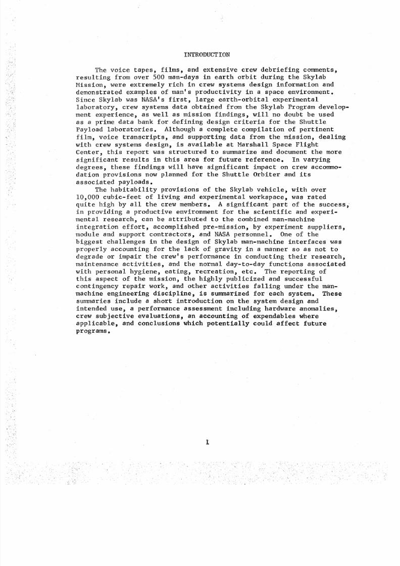
INTRODUCTION
The voice tapes, films, and extensive crew debriefing comments,
resulting from over 500 man-days in earth orbit during the Skylab
Mission, were extremely rich in crew systems design information and
demonstrated examples of man's productivity in a space environment.Since Skylab was NASA's first, large earth-orbital experimental
laboratory, crew systems data obtained from the Skylab Program develop-
ment experience, as well as mission findings, will no doubt be used
as a prime data bank for defining design criteria for the Shuttle
Payload laboratories. Although a complete compilation of pertinent
film, voice transcripts, and supporting data from the mission, dealing
with crew systems design, is available at Marshall Space Flight
Center, this report was structured to summarize and document the more
significant results in this area for future reference. In varying
degrees, these findings will have significant impact on crew accommo-
dation provisions now planned for the Shuttle Orbiter and its
associated payloads.
The habitability provisions of the Skylab vehicle, with over
i0,000 cubic-feet of living and experimental workspace, was rated
quite high by all the crew members. A significant part of the success,
in providing a productive environment for the scientific and experi-
mental research, can be attributed to the combined man-machine
integration effort, accomplished pre-mission, by experiment suppliers,module and support contractors, and NASA personnel. One of the
biggest challenges in the design of Skylab man-machine interfaces was
properly accounting for the lack of gravity in a manner so as not to
degrade or impair the crew's performance in conducting their research,
maintenance activities, and the normal day-to-day functions associated
with personal hygiene, eating, recreation, etc. The reporting of
this aspect of the mission, the highly publicized and successfulcontingency repair work, and other activities falling under the man-
machine engineering discipline, is summarized for each system. These
summaries include a short introduction on the system design and
intended use, a performance assessment including hardware anomalies,
crew subjective evaluations, an accounting of expendables where
applicable, and conclusions which potentially could affect future
programs.
8/8/2019 MSFC Skylab Crew Systems Mission Evaluation
http://slidepdf.com/reader/full/msfc-skylab-crew-systems-mission-evaluation 26/397
8/8/2019 MSFC Skylab Crew Systems Mission Evaluation
http://slidepdf.com/reader/full/msfc-skylab-crew-systems-mission-evaluation 27/397
_
to be launched at the sametime. Controls and displays, associatedwith the ATM, had been located in an integrated panel designed forthe LM. With only minor modifications, this panel was placed in theMDAjust forward of the MDA/Airlock Structural Transition Section(STS) interface. The added payload capacity also permitted the addi-
tion of a series of earth resources experiments which were located inthe MDA. The functions for which the MDA was initially configured
were not the functions the MDA finally served.
B. Airlock Module (AM) and Structural Transition Section (STS)
Situated between the MDA and the Orbital Workshop. The AM/STS
configuration and functions were perhaps least affected by the
"wet to dry" decision. From the outset, this element was intended
to provide extra-vehicular activity (EVA) capability and serve as the
"systems control center" for the cluster. This module provided the
cluster with its two-gas control systems, power distribution andcontrol system, and data/communications systems. Most of these
systems controls were located in the STS adjacent to the MDA. The
crew station associated with these controls envisioned the crewman
positioned with his feet secured in the MDA. When the ATM controland display panel was later repositioned to the MDA, the STS control _
crew station was slightly compromised.
C. Orbital Workshop (OWS)
Originally, activities associated with the OWS consisted of
little more than demonstrating that a spent propulsive stage could
be rendered safe enough for entry and habitation. Plans for use of
the OWS gradually became more ambitious, but the "wet to dry" decision
exerted the most significant influence over the internal designfeatures of the S-IVB stage. The open grid, widely used in the OWS
for floors, ceilings, and partitions and originally developed
primarily to permit the unobstructed flow of liquid hydrogen during
powered flight, was now to serve two important functions; to allow
the free flow of ventilation sir and provide widely available crew
mobility and stability aids. The floor plan, which evolved during
the "wet" period, was heavily influenced by the need for access to
various tank penetrations and the requirement for simplicity in as
much as few OWS systems could be preinstalled, since few could with-
stand exposure to liquid hydrogen. The first crew would have been
faced with the large task of converting a rocket fuel tank into a
habitat. The number of separate compartments was held to a minimum
and included a large forward compartment, an aft experiment area
primarily devoted to biomedical experimentation, s combined waste
management and hygiene compartment, a food management compartment,
and two sleep compartments--one standard and one experimental. Later,
the requirement for the experimental sleep compartment was deleted
8/8/2019 MSFC Skylab Crew Systems Mission Evaluation
http://slidepdf.com/reader/full/msfc-skylab-crew-systems-mission-evaluation 28/397
thus allowing the food managementcompartment to be enlarged. Other-wise, the crew quarters floor plan was unchangedfrom its initial"wet" launch configuration. Thus, the OWSgeneral arrangement waslargely determined by early program constraints, most of which werelater eliminated.
Although the OWSgeneral arrangement was virtually unaffectedby the "wet to dry" decision, it then becamepossible to preinstallmost of the habitability provisions. Increased payload capabilitypermitted more liberal weight allowances for systems and expendablesthereby permitting more ambitious mission planning and allowing forhabitability improvements. For example, it becamepossible to addan active food freezer/chiller system thereby enhancing the qualityof food. Additionally, since the OWSwould never be exposed toliquid hydrogen, it was possible to add a viewing window, relocatethe scientific airlocks from the STSto the OWSorward compartment,and install an airlock, across the LOX/LH2commonbulkhead, to createa trash container in the unused oxidizer tank. All of the items
previously launch-stowed in the MDAfor later deployment in the OWScould be "launched in place." This reduced activation time andpermitted a far more ambitious subsystem design.
During the early evolution of the OWS,designers consciouslyattempted to retain a "visual gravity vector", i.e., one surface wasdesignated as the "floor" with all nomenclature and operationsplanned around this reference surface. While it was recognized that"up" and "down" designators are arbitrary in a weightless environment,it was felt that it should be observed unless there was a strongreason to deviate from the chosen convention. As designed evolved,certain deviations were made in the OWS. The sleep restraints weresuspendedbetween the "floor" and "ceiling" and use of the fecalcollector demandedhat the crewman"sit on the wall." In other partsof the vehicle, layout considerations appeared to legislate againstmaintaining consistent conventions. In the MDA,operation of the ATMconsole required a crew position approximately 90-degrees to thevehicle center line, while monitoring of the nearby STScontrols anddisplays required that crewmenorient themselves parallel with thevehicle axis.
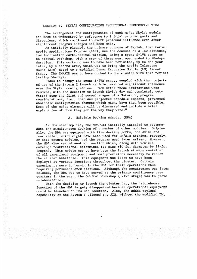
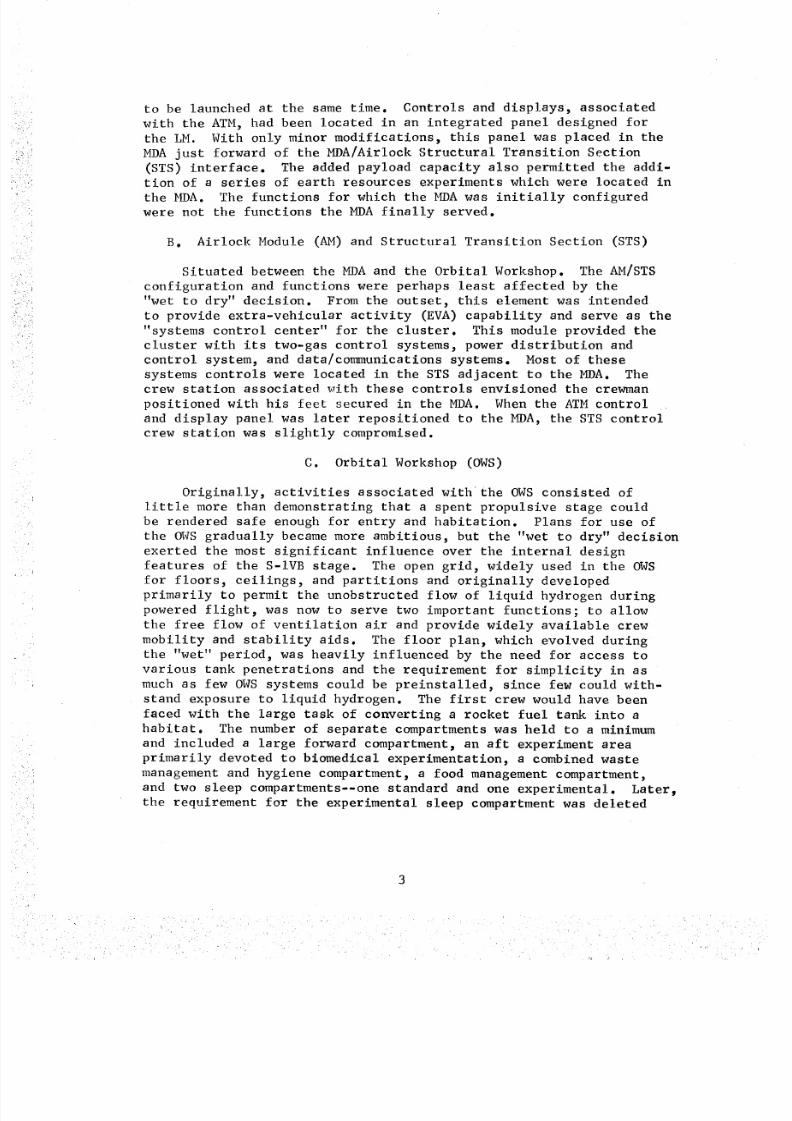
The original AAPvehicle configuration is illustrated in Figurei. The "as-flown" Skylab vehicle configuration, i.e., depicting thethermal curtain and the missing Solar Array Systemwing assembly, isprovided in Figure 2.
This report does not attempt to trace the design evolution ofeach system through development of the Skylab Program, but onlydescribes and assesses system performance as finally designed.
4
8/8/2019 MSFC Skylab Crew Systems Mission Evaluation
http://slidepdf.com/reader/full/msfc-skylab-crew-systems-mission-evaluation 29/397
Figure I. AAPVehicle Configuration - 1967i] i ii i F i i i I i i i il
Figure 2. Skylab "As-Flown" Configuration
8/8/2019 MSFC Skylab Crew Systems Mission Evaluation
http://slidepdf.com/reader/full/msfc-skylab-crew-systems-mission-evaluation 30/397
SECTIONI. HABITABILITY,ARCHITECTURAL,NDCREWPROVISIONS
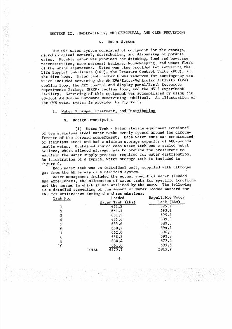
A. Water System
The OWSwater system consisted of equipment for the storage,microbiological control, distribution, and dispensing of potable
water. Potable water was provided for drinking, food and beverage
reconstitution, crew personal hygiene, housekeeping, and water flush
of the urine separators. Water was also provided for servicing the
Life Support Umbilicals (LSU), the Pressure Control Units (PCU), andthe fire hose. Water tank number 6 was reserved for contingency use
which included servicing the AM EVA/Intra-Vehicular Activity (IVA)
cooling loop, the ATM control and display panel/Earth Resources
Experiments Package (EREP) cooling loop, and the M512 experiment
facility. Servicing of this equipment was accomplished by using the60-foot AM Sodium Chromate Deservicing Umbilical. An illustration of
the OWS water system is provided by Figure 3.
I. Water Storage, Treatment_ and Distribution
a. Design Description
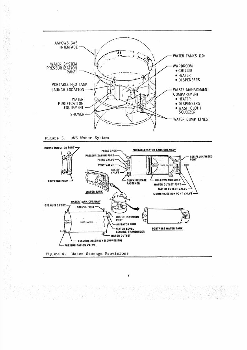
(i) Water Tank - Water storage equipment consisted
of ten stainless steel water tanks evenly spaced around the circum-
ference of the forward compartment. Each water tank was constructed
of stainless steel and had a minimum storage capacity of 600-pounds
usable water. Contained inside each water tank was a sealed metal
bellows, which allowed nitrogen gas to provide the pressurant to
maintain the water supply pressure required for water distribution.
An illustration of a typical water storage tank is included in
Figure 4.Each water tank was an individual unit, supplied with nitrogen
gas from the AM by way of a manifold system.
Water management included the actual amount of water (loaded
and expellable), the allocation of water tanks for specific functions,
and the manner in which it was utilized by the crew. The following
is a detailed accounting of the amount of water loaded onboard the
OWS for utilization during the three missions.Tank No. Loaded Expellable Water
Water Tank _Lbs_ _ Tank __Lbs)I 661.2 595.2
2 661.1 595.1
3 661.2 595.2
4 655.6 589.6
5 655.6 589.6
6 660.2 594.2
7 662.0 596.0
8 658.8 592.8
9 638.4 572.4
I0 661.6 595.6TOTAL 6575.7 5915.7
8/8/2019 MSFC Skylab Crew Systems Mission Evaluation
http://slidepdf.com/reader/full/msfc-skylab-crew-systems-mission-evaluation 31/397
AM.,'OWSGAS ..f""-"--'"_'"
I NTERFACE_. ,.__/
PRESSUR IZATION • CHILLER
PANEL :, ....I- ..... "----- .._L.
PORTABIF HoO TANK "°I__'/_ _"_(. F" • "" '_,_A°NC.OCA_,ON__+-_-_ \_
PURIrICATI_C'__ L_ ..,EQUIPMENT_{:// __::_ --_il
i7_.--:-.._._4 _-/.y".,l ---
• HEATER• DISPENSERS
WASTEMANAGEMENTCOMPARTMENT
• HEATER• DISPENSERS• WASH CLOTH
SQUEEZER
WATERDUMP LINES
Figure 3. OWS Water Systemi
IOOINE INJECTION PORT 7 PRESS GAGE_ PORTABLE WATER TANK CUTAWAY
PRESSURIZATION PORT'-",. "% " " " " " " GSEFLUSH/BLEEO
PRESSVALVE "'--_--_ PORT
VENT VALVE _'_,_'Ntl__ I (J _tctiu_ w,_* c_,* _h'lIA'ii.-_
.ELI."<J,_CI _l_fl 1A;-_ kVALVEJ,,_ ,wv_.. .__ \
__llla WATER OUTLET VALVE-'-1' _
IODINE INJECTION PORT VALVE ---'_
WATER ':'ANK CUTAWAY
GSEBLEED PORT
L,o ;, , _y,_E..E_,O.
•.t _ .- WATE,EVEL POR.AB.E
ATER,A.
/ _ WATERU.ET
Figure 4. Water Storage Provisionsnl l
8/8/2019 MSFC Skylab Crew Systems Mission Evaluation
http://slidepdf.com/reader/full/msfc-skylab-crew-systems-mission-evaluation 32/397
The water tanks carried onboard the OWS were allocated for use
as follows:
Tank No. Sequential Usage
i2
3_
4
5
6
7
I0
First Wardroom Tank - First MissionThird Wardroom Tank - Second Mission
Fourth Wardroom Tank - Third MissionFifthWardroom Tank - Third Mission
Sixth Wardroom Tank
Urine Flush/Contingency Tank/Fire Hose
First Waste Management Compartment Tank-First/
Second Mission
Second Waste Management Compartment Tank-Second/
Third Mission
Contingency (Wardroom or Waste Management/EVA
Suit LoopSecond Wardroom Tank - Second Mission
(2) Water Tank Heater Blankets - Each water tank was
provided protection against freezing by an electrical heater blanket
wrapped around the circumference of the tank. The heater blanket was
controlled by an electronic module, including a backup thermostat,
and was designed to maintain the water temperature between 56-60°F
during uninhabited periods. Due to the elevated temperatures during
the missions, the water tank heaters were not operated.
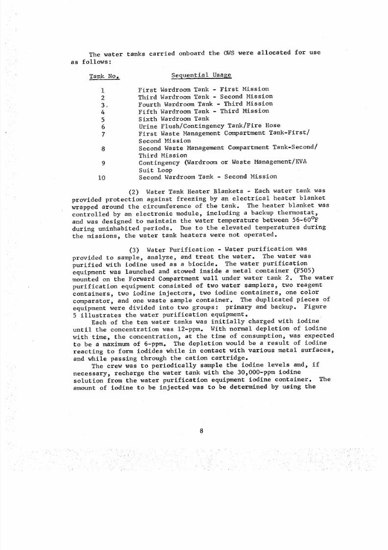
(3) Water Purification - Water purification was
provided to sample, analyze, and treat the water. The water was
purified with iodine used as a biocide. The water purification
equipment was launched and stowed inside a metal container (F505)mounted on the Forward Compartment wall under water tank 2. The water
purification equipment consisted of two water samplers, two reagent
containers, two iodine injectors, two iodine containers, one color
comparator, and one waste sample container. The duplicated pieces of
equipment were divided into two groups: primary and backup. Figure
5 illustrates the water purification equipment.Each of the ten water tanks was initially charged with iodine
until the concentration was 12-ppm. With normal depletion of iodine
with time, the concentration, at the time of consumption, was expected
to be a maximum of 6-ppm. The depletion would be a result of iodine
reacting to form iodides while in contact with various metal surfaces,
and while passing through the cation cartridge.
The crew was to periodically sample the iodine levels and, if
necessary, recharge the water tank with the 30,O00-ppm iodine
solution from the water purification equipment iodine container. The
amount of iodine to be injected was to be determined by using the
8

8/8/2019 MSFC Skylab Crew Systems Mission Evaluation
http://slidepdf.com/reader/full/msfc-skylab-crew-systems-mission-evaluation 33/397
i,i
WATER SAI'J1PLEANALYSIS WATERCONTAINER INJECTOR
IODINEADDITIONCHART ---,
2PUSHBUTTONVENT VALVESLOCATEO ONDOOR SLOE-",
@
_Z IODINEZ INTROOUCTION
PROCEDURE
+Y
o %IODINECONTAINER
© ©IODINECONTAINER
WATER
REAGENTCONTAINER
ILORCOMPARATOR
IODINEINJECTOR
Figure 5. Water Purification Equipmentii i
"iodine addition chart", which scheduled water tank volume (%) and
iodine concentration. In order to provide safe drinking water, the
iodine concentration was to have been 0.5 ppm or greater. Sampling
equipment and a color comparator provided the crew a means of period-
ically determining the iodine concentration to ensure that the level
was always above 2-ppm. If the level was low, the crew was to use
an iodine injector to increase the iodine concentration.
(4) Nitrogen (N2) Distribution Network - The water
system N 2 distribution network provided a regulated gas supply to
each of the water tanks. This gas supply was used to operate the
water storage tank bellows to allow for water expulsion. The source
of the N2 distribution network gas supply was the 4000-psig N 2
tanks in the AM, which were regulated to 150-psig in the AM and then
to 35-psig in the OWS.
(5) Tank N 2 Chamber - The water tank N2 chamber
consisted of a dome and metallic bellows in each of the water tanks.
At launch, each of the tank N 2 gas chambers was pressurized to 30-psigwith the gas pressurization valve on each tank closed.
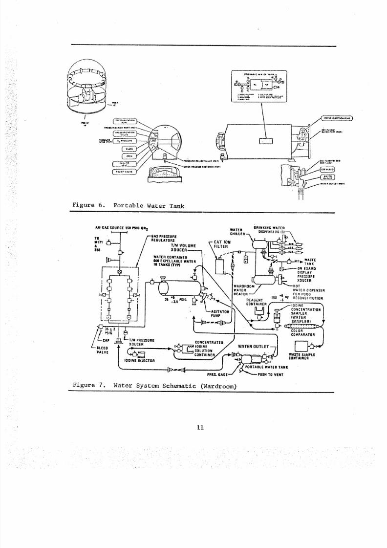
(6) Portable Water Tank - The portable water tank was
provided for sterilization of the water distribution system during
second and third mission activation. It was also provided to serve
8/8/2019 MSFC Skylab Crew Systems Mission Evaluation
http://slidepdf.com/reader/full/msfc-skylab-crew-systems-mission-evaluation 34/397
as a contingency water supply in the event of failure of the normal
water distribution system. The portable water tank was launched with
the iodine solution containing 30,000-ppm and when filled with
approximately 26-pounds of water, the iodine concentration would be
lO0-ppm. The solution was then to be injected into the water distrib-
ution system for a biocide soak. An illustration of the portable
water tank is included in Figure 6.
(7) Cation System - The water cation system (deioniz-
ation cartridge) consisted of a stainless steel container holding
approximately 66-cubic inches of ion exchange resin. The function
of this system was to remove metal ions from the water as it passed
through the resin bed. The resin bed was pretreated prior to flight
and at the end of each mission to compensate for the absorption of
iodine, which would have adversely affected the water system.
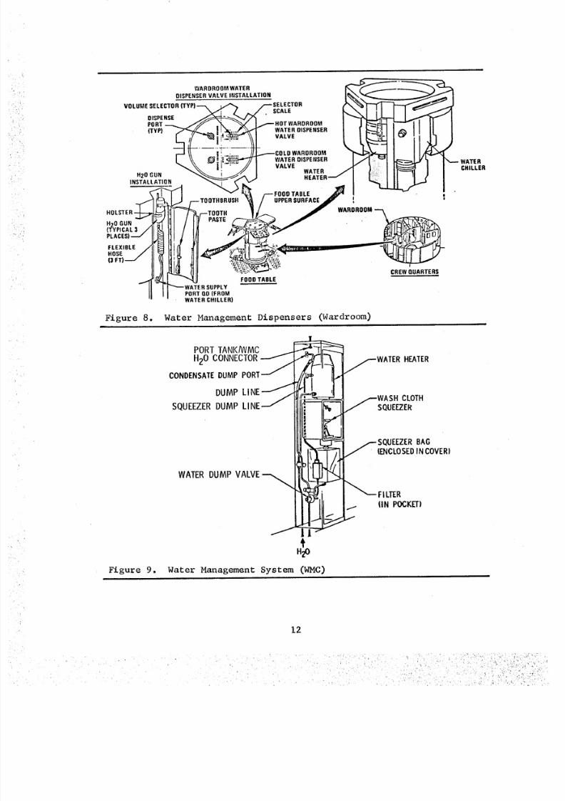
(8) Wardroom Water Distribution - The Wardroom
distribution system consisted of a flex line from the designatedwater storage tank to a hard line on the upper wall of the habitationarea. The hard line extended down the wall to the crew quarters
floor, underneath the floor to the Wardroom table. In the table, itbranched to both the water heater and chiller. The heater was
connected to a food and beverage reconstitution dispenser extending
through the top of the table. The chiller was connected to a food
and beverage reconstitution dispenser and three individual drinking
guns. A schematic of the Wardroom water system is provided by
Figure 7. An illustration of the Wardroom water dispensing equipment
is included as Figure 8.
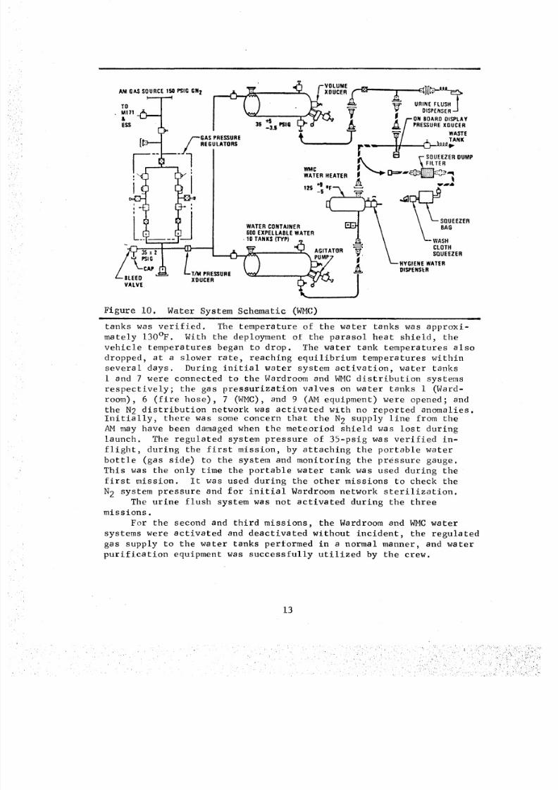
(9) Waste Management System Water Distribution - The
waste management water system provided water for personal hygiene and
urine flush. The personal hygiene water was supplied by a flex line
from a water storage tank via a hard-line network extending to the
personal hygiene locker (H825) in the Waste Management Compartment
(WMC), where it connected to the water heater. Figure 9 illustrates
this system.
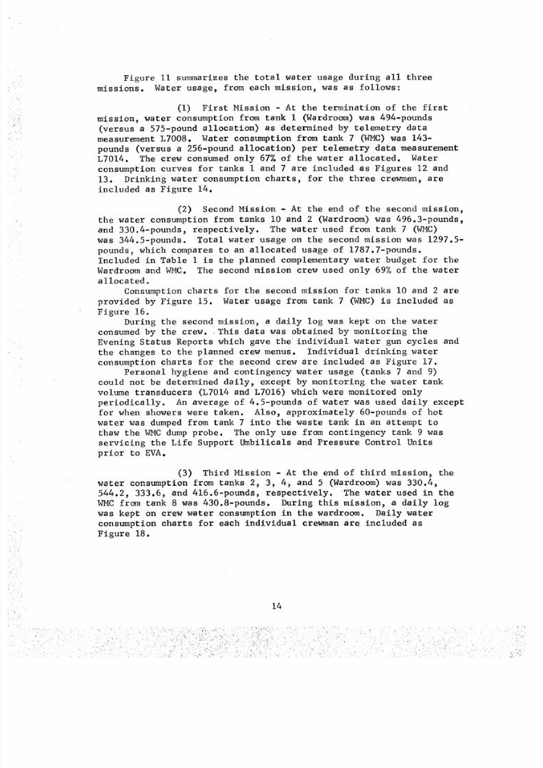
The urine flush system consisted of a supply network from water
tank 6 to a dispenser in the WMC which could meter 50-ml increments
of water/iodine solution to flush the urine separators daily, if
needed.
A schematic of the WMC water system is provided by Figure i0.
b. Post Mission Assessment - The water tanks survived thelaunch environment with no apparent problems. There was initial
concern for the integrity of the water tanks during the time period
between launch and habitation. Because of the elevated temperatures
in the OWS, it was feared that the water would expand and damage the
bellows. Upon arrival of the first crew, the integrity of the water
i0
8/8/2019 MSFC Skylab Crew Systems Mission Evaluation
http://slidepdf.com/reader/full/msfc-skylab-crew-systems-mission-evaluation 35/397
/
PnIUlURIZA_O_ PORT qRzpl
e_'rloN
_r,i mlFi
OlN pR_I m L I F VA_V_ IR
VENT Q_CK RI_LIEASIIIAITINI[A ImlFI
Figure 6. Portable Water Tank
POAIAIII.| WAT II l AN K
_ _:;_,', ...
cse FLVSMInllid
WATlnC_'VL
AM GAS SOURCE IBO P_IG ;N_t WATER ORINKING WATER
/--GAS PREfigURE CHILLER OIS,PENSERS (3)---%
TO z ' /REGULATORS "AT ,0" "-_.il_ _.
M171 .(_._ / T/M VOLUME _" _ ', LTE R m _I_
_ I I WA_RCO_rAIRER _" i _ I ___ -[_+"-"_ . / 600 EXPELLABLE WATER I'-'1 _1, [] I "_'.._,'_,_....r...._l_l_ WASTE/ # IB TANKS ITYfl -- I I _ _ I J'- I "" - T_NX
r------1------'-i -/ I I '_" I _ 8------o_ UOARU
,, _ F'_ * ,l, i'L "T" % I I_ J--I E.- XOUCER, -X _ I _ _- \ iWARORO0_--"--_ -'---.o_:
WATER WATER DISPENSER
•7_ ._,'1 -311l is P,Sl(i IJ--__/_J_ _d "":A:ENT 150 '_flIF RECONSTITUTION
/ . <-;:';'*°"l'i\
/ 'r-CAP . c_ -_ "- 'T _V _, P_ R ES SU RE . CONCENTRATED t / F"*"_.li_ J
/BLEED '_ ^_,_cn i i_IODINE / WATEROUTLET--,,TI L_..._l',ll"
" _ SOLUTION . ' WAST PALVE_ "l< GONTA'"ER/,.-_II_,_=_,DJ.JSA=.
/ '°°"'_°*" "- "1 _*- ""*'"J f POJI"P¥_'A_LE WATER TANK
Figure 7. Water System Schematic (Wardroom)
II
8/8/2019 MSFC Skylab Crew Systems Mission Evaluation
http://slidepdf.com/reader/full/msfc-skylab-crew-systems-mission-evaluation 36/397
8/8/2019 MSFC Skylab Crew Systems Mission Evaluation
http://slidepdf.com/reader/full/msfc-skylab-crew-systems-mission-evaluation 37/397
• VOLUME_O,_,OURCE,.P"GG",_ :_ _. /-XOU_ER,"e .... _ _][_"--_f rq
E= J. I 3s __j _,G _-_ _ _ ,&/PRESSUREXOUCER'_ _ _"/ WASTE(r,--- /--I;_;L%U._ t . j_,,,.:_ T/ ._4,_""
:-,_rh rh_ : I WA FE R H EATER I _ _ _"'_
I c_ _ ] I ...-.I \ \ _"- SQUEEZER
I T I I I WATERONTAINER _ \ _BAGI ['T] ___E___._J | 60 0 E XP ELL ABL E WATE R I \L'--'T .... ,i,'-'_ I • 10 TANK S (' rY P) _ A \ _--'WASH
. • _ CLOTHt _ AGITATOR
_" _IG _ _ PuMpATOR _' \ SQUEEZER/ "_ ' L / -- ( _ _'_'7 ] _--'HYGIENE WATER
CAP , _ DISPENSERL.,.2. k L-T,.PRE=O., ,BLEED XDUCER _ _/",..,_ I
VALVE Y"O /
Figure I0. Water System Schematic (WMC)
tanks was verified. The temperature of the water tanks was approxi-
mately 130°F. With the deployment of the parasol heat shield, the
vehicle temperatures began to drop. The water tank temperatures also
dropped, at a slower rate, reaching equilibrium temperatures within
several days. During initial water system activation, water tanks
i and 7 were connected to the Wardroom and WMC distribution systems
respectively; the gas pressurization valves on water tanks i (Ward-room), 6 (fire hose), 7 (WMC), and 9 (AM equipment) were opened; and
the N2 distribution network was activated with no reported anomalies.
Initially, there was some concern that the N 2 supply line from theAM may have been damaged when the meteoriod shield was lost during
launch. The regulated system pressure of 35-psig was verified in-
flight, during the first mission, by attaching the portable water
bottle (gas side) to the system and monitoring the pressure gauge.
This was the only time the portable water tank was used during the
first mission. It was used during the other missions to check the
N 2 system pressure and for initial Wardroom network sterilization.
The urine flush system was not activated during the threemissions.
For the second and third missions, the Wardroom and WMC water
systems were activated and deactivated without incident, the regulated
gas supply to the water tanks performed in a normal manner, and water
purification equipment was successfully utilized by the crew.
13
8/8/2019 MSFC Skylab Crew Systems Mission Evaluation
http://slidepdf.com/reader/full/msfc-skylab-crew-systems-mission-evaluation 38/397
Figure ii summarizes the totsl water usage during all three
missions. Water usage, from each mission, was as follows:
(i) First Mission - At the termination of the first
mission, water consumption from tank i (Wardroom) was 494-pounds
(versus a 575-pound allocation) as determined by telemetry datameasurement L7008. Water consumption from tank 7 (WMC) was 143-
pounds (versus a 256-pound allocation) per telemetry data measurement
L7014. The crew consumed only 67% of the water allocated. Water
consumption curves for tanks i and 7 are included as Figures 12 and
13. Drinking water consumption charts, for the three crewmen, are
included as Figure 14.
(2) Second Mission - At the end of the second mission,
the water consumption from tanks I0 and 2 (Wardroom) was 496.3-pounds,
and 330.4-pounds, respectively. The water used from tank 7 (WMC)
was 344.5-pounds. Total water usage on the second mission was 1297.5-
pounds, which compares to an allocated usage of 1787.7-pounds.Included in Table I is the planned complementary water budget for the
Wardroom and WMC. The second mission crew used only 69% of the water
allocated.
Consumption charts for the second mission for tanks I0 and 2 are
provided by Figure 15. Water usage from tank 7 (WMC) is included as
Figure 16.
During the second mission, a daily log was kept on the water
consumed by the crew. This data was obtained by monitoring the
Evening Status Reports which gave the individual water gun cycles and
the changes to the planned crew menus. Individual drinking water
consumption charts for the second crew are included as Figure 17.Personal hygiene and contingency water usage (tanks 7 and 9)
could not be determined daily, except by monitoring the water tank
volume transducers (L7014 and L7016) which were monitored only
periodically. An average of 4.5-pounds of water was used daily except
for when showers were taken. Also, approximately 60-pounds of hot
water was dumped from tank 7 into the waste tank in an attempt to
thaw the WMC dump probe. The 0nly use from contingency tank 9 wasservicing the Life Support Umbilicals and Pressure Control Units
prior to EVA.
(3) Third Mission - At the end of third mission, the
water consumption from tanks 2, 3, 4, and 5 (Wardroom) was 330.4,
544.2, 333.6, and 416o6-pounds, respectively. The water used in the
WMC from tank 8 was 430.8-pounds. During this mission, a daily logwas kept on crew water consumption in the wardroom. Daily water
consumption charts for each individual crewman are included as
Figure 18.
14
8/8/2019 MSFC Skylab Crew Systems Mission Evaluation
http://slidepdf.com/reader/full/msfc-skylab-crew-systems-mission-evaluation 39/397
_o0
_OO
7O0
=600
I
>
300
100
OATA (FIRb'T I. : TELEMETRY'
MISSION} |
ALLLATEO _0
_"_oo
(116.0 LBS UNUSABLE
o I 1 f I I I I I I I I I I l I I I I I I I I I I 1 1 I 1 I I 14 6 8 10 12 14 16 18 30 22 24 Z_S _8 30 32
M IS SI ON OAY
Figure 12. Water Consumption - Tank No. i (Wardroom) - First Mission
15
8/8/2019 MSFC Skylab Crew Systems Mission Evaluation
http://slidepdf.com/reader/full/msfc-skylab-crew-systems-mission-evaluation 40/397
1.000
900
8OO
7O0
8OO
500
400
300
100
O
O TELEMETRY IDATA ( FI RS TMISSION)
_.......T_.6 LBS
O OQ (_ REMAING.
O®0
USABLE
ALLOCATED CONSUMPTION J --_ 439 LBS3 91 L BS --
B4S.O LBS UNUSABLE
I I I I I I I I I I I I t I I I 1 I I I I I 1 I I I 1 I I I 12 4 6 8 10 12 14 16 18 20 22 24 26 28 30 32
MI SS ION D AY
Figure 13. Water Usage - Tank No' 7 (WMC) - First Mission
/- o_s ACT,V*',ON PLT -- W(tCZ
JvE
II]llJl)llll IIIIllllllllllllllllllllllllll
i,ori
,o)
l _ o_s *CT,VM,O_SO
M,SllO_ OMV
Figure 14. Drinking Water Consumption - First Mission
16
i :" .. ' - , :
8/8/2019 MSFC Skylab Crew Systems Mission Evaluation
http://slidepdf.com/reader/full/msfc-skylab-crew-systems-mission-evaluation 41/397
8/8/2019 MSFC Skylab Crew Systems Mission Evaluation
http://slidepdf.com/reader/full/msfc-skylab-crew-systems-mission-evaluation 42/397
>
1,000
SiX)
BOO
700
6OO
50O
4OO
3O0
10C
0
Q ACTU AL US AGE
_ALLOCATED
F"TANK 8ALLOCATED
TANK ? USAGE lQOQ O
e C_O_
cD Q
ALLOCATED "--I
--.qI t I I I I I I I f t I I I
4 9 12 16 20 24 28 32 36 40 44 48 52 56
MI SS ION OAY S
°O
Figure 16. Water Usage - Tank No. 7 (WMC) - Second Mission
,lo
ioo
oo
t_
so
s_
*o
Jo
;,o
to
o
,,o
,oo
_o
Z| Jo
"--'-'-_' I-1 _ _ -u_qj__slr_n_-__ -UI1t I 1 I I I I I I I I I I I I I I I I I I I t I I I I I I I I I I I i I I I I i
,,e, oo i -
ooL
1o
lo
:[ n_ _ FL,_or_ o .. _:or--r--,--rr_T _ _u uu b_<--u-L_%.'ol_,,,,_,.,,-,,,, ,,, ,,,,,,,, ,, I...,_,. ;.;. :._,...
i • i i )o tl i_ li ii i 3,'4 II a ill ii I1 14 x i 4_1 II 44 I ill i(i ii ill H i I lul_o_ OAr
Figure 17. Drinking Water Consumption - Second Mission
18
8/8/2019 MSFC Skylab Crew Systems Mission Evaluation
http://slidepdf.com/reader/full/msfc-skylab-crew-systems-mission-evaluation 43/397
_'o co_ - CAAR
)o
'Po
,o
o
*,o
lee
go---.
:[ rFigure 18. Drinking Water Consumption - Third Mission
|, ,
The following water samplings and iodine injections were
performed, during the three missions, to maintain water purity:
Water Sampling
DOY 147
DOY 147
DOY 148
DOY 153
DOY 153
DOY 153
DOY 153
DOY 158
DOY 211
DOY 211
DOY 211
DOY 226
DOY 226
DOY 233
DOY 233DOY 233
DOY 238
DOY 265
DOY 265
Water Tank No. i
Water Tank No. 7
Wardroom Chiller
Water Tank No°l
Water Tank No. 3
Water Tank No. 6
Water Tank No. i0
Wardroom Chiller
Water Tank No. i0
Water Tank No. 7
Wardroom Chiller
Water Tank No. 3
Water Tank No. 4
Water Tank No. 2
Water Tank No. 8Water Tank No. 9
Wardroom Chiller
Water Tank No. 2
Water Tank No. 5
2.0 ppm
2.0 ppm3.8 ppm
9.0 ppm
8.0 ppm
I0.0 ppm
i0.0 ppm
1.0 ppm
6.0 ppmData Not Available
7.0 ppm
4.0 ppm
7.0 ppm
5.0 ppm
3.0 ppm
0.0 ppm
3.5 ppm
2.0 ppm
6.0 ppm
19
8/8/2019 MSFC Skylab Crew Systems Mission Evaluation
http://slidepdf.com/reader/full/msfc-skylab-crew-systems-mission-evaluation 44/397
DOY 265
DOY 324
DOY 337
DOY 338
DOY 339DOY 340
DOY 340
DOY 341
DOY 342
Wardroom Chiller
Water Tank No. 3
Water Tank No. 4
Water Chiller
Water Tank No. 5Water Tank No. 5
Water Tank No. 6
Water Tank No. 8
Wster Tank No. 9
Data Not Available
8.0 - 9.0 ppm
5.0 ppm
9.0 ppm
6.0 ppm9.0 ppm
6.0 ppm
4.0 ppm
1.0 ppm
Iodine Injections
DOY 147 Water Tank No. i 40 Units
DOY 172 Cation Filter 17 Units
DOY 211 Wardroom Network Soak 40 Units
DOY 238 Water Tank No. 3 25 Units
DOY 238 Wate_r Tank No. 5 40 Units
DOY 238 Water Tank No. 7 30 Units
DOY 238 Water Tank No. 8 30 Units
DOY 238 Water Tank No. 9 90 Units
DOY 267 Water Tank No. 2 15 Units
DOY 267 Cation Filter 17 Units
DOY 324 Water Tank No. 3 30 Units
DOY 337 Water Tank No. 4 20 Units
DOY 339 Water Tank No. 5 20 Units
DOY 340 Wster Tank No. 6 20 Units
DOY 341 Water Tank No. 8 20 Units
DOY 342 Water Tank No. 9 75 Units
A total of 529 cc of iodine solution was injected into the watersystem. The amount of iodine solution available onboard was 2760cc
(30,000 ppm), leaving a remainder of 2231cc at the end of the third
mission. Water system samples were returned from each mission.
Comprehensive analyses were conducted on each sample, with the results
shown in Tables 2, 3 and 4.
The WMC water dump system operated normally during the first
mission. However, during the second mission, the WMC water dump
heater probe failed due to icing. The probe was removed and replaced
with a spare unit. The system then operated in a normal manner. An
electrical check was performed on the probe with no indication of
heater malfunction. Prior to the dump heater probe replacement,
hot water was dumped into the system in an attempt to clear the
obstruction. The WMC system onboard pressure gauge read off-scale
high (2-psia) regardless of the time the system was evacuated into
the waste tank. Additional troubleshooting revealed a pressure
transducer failure. The crew was instructed to vent overnight and
then activate the system, since gas in the WMC presented no problems
2O
8/8/2019 MSFC Skylab Crew Systems Mission Evaluation
http://slidepdf.com/reader/full/msfc-skylab-crew-systems-mission-evaluation 45/397
prope[tles
E le ct ric al C on du cti vit y
(Micromno/cm @ 25°C)
PH (6 25°C)
Total Residue (mg/l)
Taste and Odor (at 45oc)
Turbidity (Units)
Color True (Units)
Dissolved Gases (% by Volume) i
Limits
Reference Only
4-8
91.
Reference Only
II
Reference Only
0.5
Bioclde (ppm)
Particulate/500 ml
0-I0 Microns
10-25 Microns
25-50 Microns
50-100 Microns100-250 Microns
Sterility
Total Bacteria
Tota l C ol if orm
Anaerobic AnalysisYeast and Molds
Ionic Species in mg/ml
Cadmium
Calcium
Chromium (hex)
Copper
IronLead
Manganese
MercuryNickel
Silver
Zinc
Iodide
Selenium
12
Silicon
Potassium
Magnesium
Sodium
Arsenic
Aluminum
Reference Only
Reference Only
Reference Only
Reference Only
Reference OnlyReference Only
Negative
Negative
Negative
Negative
0.01
5.6
0.05
1.0
0.30.05
0.05
0.005
0.05
0.05
5.0Reference
Reference
Results
3.6 X I0
4.6
9 Nephelos UnitsI '
-m
0.01
0.01
0.05
0.I Filtered 0.020.050.01
0.0050.05
0.1125
0.01
0.5
0.5
7.0
0.5
0.i
0.I
0.5
Table 2. Potable Water - Tank No. i - First Mission
ii i l J , i i
21
r
8/8/2019 MSFC Skylab Crew Systems Mission Evaluation
http://slidepdf.com/reader/full/msfc-skylab-crew-systems-mission-evaluation 46/397
Table 3.
Properties
El ect ri cal Co ndu ct ivi ty
(Micromho/cm @ 25°C)
PH (@ 25%)
Total Residue (mg/1)Taste and Odor (at 45°C)
Turbidity (Units)Color True (Units)Dissolved Gases (% by Volume)
Bioeide (ppm)
Partlculate/500 ml
0 -I 0 Mi cro ns
10-25 Microns
25-50 Microns
50-100 Microns
100-250 Microns
S.terillty (Colonies/150 m l)
Total Bacteria
Total Coliform
Anaerobic Analysis
Yeast and Molds
Ionic Species in mg/ml
Cadmium
Calcium
Chromium (hex)
CopperIron
Lead
Manganese
MercuryNickel
Silver
Zinc
Iodide and Iodine
Selenium
12Silicon
Potassium
MagnesiumSoclum
ArsenicAluminum
Additional Data
Nitrogen (ppm)
Nitrate (ppm)Nitrite (ppm)
Limits
Reference Only
4-8
91.
Reference Only
II
Reference Only
0.5
Reference Only
Reference Only
Reference Only
Reference only
Reference Only
Reference Only
Negative
Negative
Negative
Negative
0.015.60.05
1.00.3
0.050.050.005
0.05
0.055.0Reference "Reference
.. Results
32
4.8
55 to 10
.m
.01
.I
.02
.01
.29
.02
.01
.005
.03
.02
.02
33.4
.05
.5
8.8
.5
1.74
o.
.5
.I
7.0.01
Potable Water - Tank No. 2 - Second Mission
22
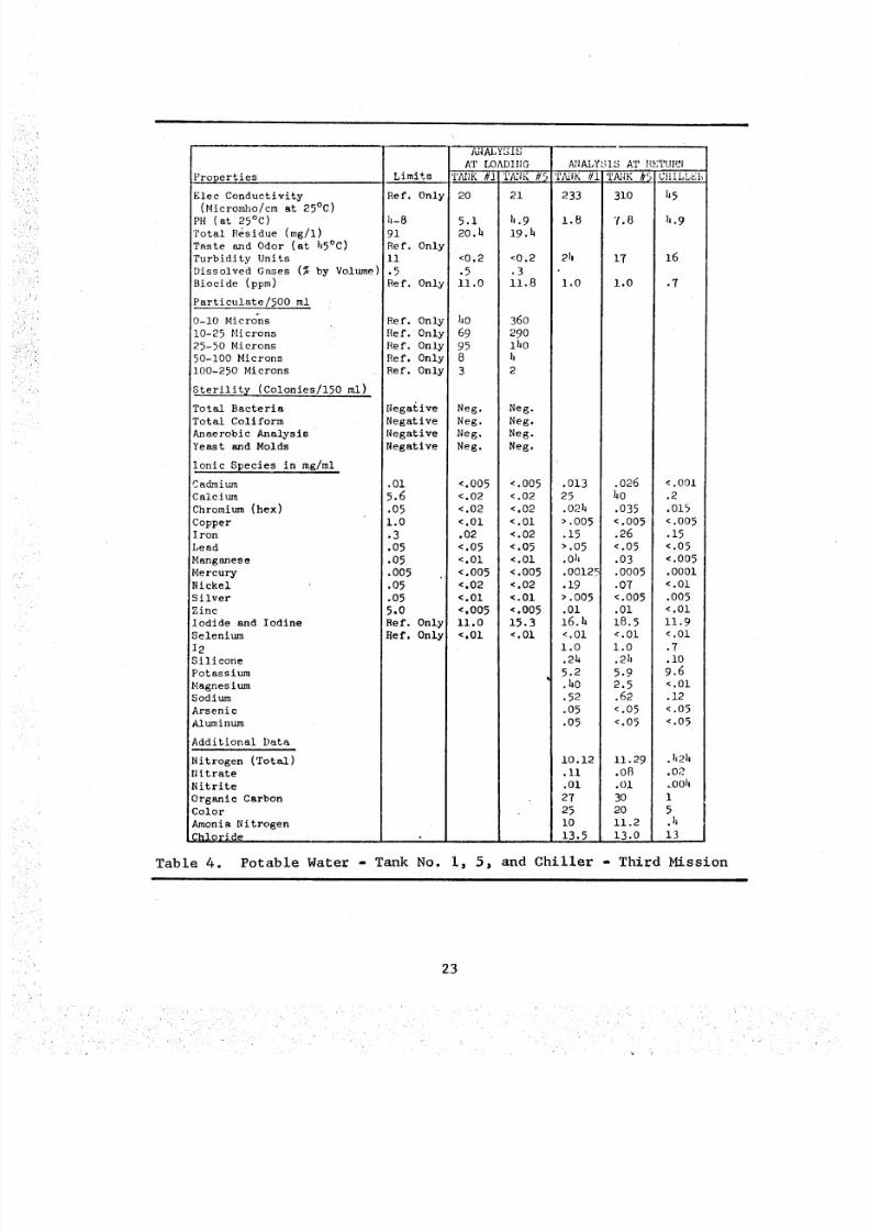
8/8/2019 MSFC Skylab Crew Systems Mission Evaluation
http://slidepdf.com/reader/full/msfc-skylab-crew-systems-mission-evaluation 47/397
Properties
Elee Conductivity(Micromho/cm at 25°C)
PH (at 25°C)
Total Residue (mg/1)
Taste and Odor (at hSOC)
Turbidity Units
Dissolved Gases (% by Volume)
Biocide (ppm)
Particulate/500 ml
0-i0 Microns
10-25 Microns
25-50 Microns
50-100 Microns
100-250 Microns
Sterility (Colonies/150 ml)
Total BacteriaTotal Coliform
Anaerobic AnalysisYeast mud Molds
Ionic Species in mg/ml
Cadmium
Calcium
Chromium (hex)
CopperIron
Lead
Manganese
MercuryNickel
Silver
ZincIodide and Iodine
Selenium
12
Silicone
Potassium
MagnesiumSodium
Arsenic
Aluminum
Additional Data
Nitrogen (Total)N i t r at e
Nitrite
Organic Carbon
ColorAmoni a Nitrogen
Chloride
Table 4.
m..
Potable Water - Tank No.
ANALYSIS
AT LOADING
Limits 'l'_dIK#i TiU_K #_
Ref, Only 20 21
h-8 5.1 h.9
91 2o. h I9. h
Re f. Only
ll <0.2 <0.2
•5 .5 .3
Ref. Only II.0 11.8
Ref. Only hO 360
Ref. Only 69 290
Ref. Only 95 lhO
Ref. Only 8 h
Ref. Only 3 2
Negative Nag. Nag.
Negative Neg. Neg.
Negative Nag. Neg.
Negative Neg. Nag.
•01 <.005 <.005
5.6 <.02 <.02
•05 <.02 <.02
1.0 <.01 <.01
•3 .02 <.02
.05 <.05 <.05
•05 <.01 <.01
.005 <.005 <.005
• 05 <.02 <.02
.05 <.01 <.01
5.0 <.005 <.005Ref. Only ii.0 15.3
Hef. Only <.01 <,01
I, 5, and Chi
ANALYSIS AT RETUI_J
TiU_K #i TN_K #_ CHILLEh
233 310 h5
1.8 7.8 h.9
21_ 17 16
1,0 1.0 ,7
.013 .026 <.001
25 ho .2
.02h •035 .015
>.005 <.005 <.005
.15 .26 .15
>.05 <.05 <.05
.Oh .03 <.005
• 00125 .0005 .0001
• 19 .07 <.O1
>.005 <.005 .005
.01 .01 <.0116.h 18.5 i1.9
<.01 <.01 <.01
1.0 i•0 .7.2h .2h •I0
5.2 5.9 9.6
.h0 2.5 <.01
.52 •62 .12
.05 <.05 <.05
•05 <.05 <.05
10.12 11.29 .1=2l,.ii .O8 .02
•Ol . Ol .00h
27 30 i
25 20 510 ll.2 .h
13.5 13.0 13
ller - Third Mission
23
8/8/2019 MSFC Skylab Crew Systems Mission Evaluation
http://slidepdf.com/reader/full/msfc-skylab-crew-systems-mission-evaluation 48/397
if the pressure indication was true. Activation, without the trans-
ducer, was no problem. The network was used throughout the second
and third missions with no further difficulty.
During the first mission, a flow decrease from the WMC hot
water dispenser was reported. The dispenser valve was replaced with
the spare unit and the flow returned to normal. The crew reportedevidence of contamination in the removed unit.
A summary of crew observations, relative to the water system_
are as follows:
• The iodine levels in the water tanks remained above the
predicted depletion rates. Iodine taste in the waterwasn't noticeable. Chilled water tended to remove the iodine
taste.
• The water temperature, both hot and cold, was excellent.
There was no condensation associated with the Wardroom
water chiller.
• The food reconstitution dispensers were adequate. The
location of the leak reported on the food reconstitution
dispenser was merely a little blow-by on the dispenser
and tended to collect on small radii, giving the appearance
of being a leak.• Recommendations were made to have the food reconstitution
water selector dispensing volume increased to 8-ounces,
compared to 6-ounces, because many of the beverage packets
required 8-ounces of water.
• There were no problems encountered distinguishing color
on the low end of the color comparator.
• The tank bellows loeator (water measuring device) worked
satisfactorily on all the water tanks because of the magnet
location stripe provided on the side of each tank.
• The tank bellows locator on the condensate tank providedless than desirable results because there was no location
stripe on the tank.
The as-flown concept of water storage, transfer, expulsion,
and general management was proven to be completely satisfactory,
workable, and feasible as an approach where weight allowance is not
a critical consideration. However_ it is generally acknowledged
that future space programs will have to explore and develop other
potential concepts, such as water reclamation, which is less
weight-costly.
24
8/8/2019 MSFC Skylab Crew Systems Mission Evaluation
http://slidepdf.com/reader/full/msfc-skylab-crew-systems-mission-evaluation 49/397
B. Waste Management System
The Waste Management System collected, sampled, processed, and
stored all crew metabolic wastes. This included provisions for
collection, preservation and management of feces, urine, and vomitus.
The major functions of the Waste Management System were to providea comfortable means for the crew to perform daily fecal and urine
eliminations and also provide a means of sampling and preserving this
material for return to the ground for biomedical analysis.
The Waste Management System consisted of a fecal/urine collector,
collection and sample bags, sampling equipment, odor control filters,
blower, waste processor, urine freezer, and other necessary supplies.
The fecal/urine collector provided means for collecting both
feces and urine using airflow, as a gravity substitute, to separate
the waste material from the body. Urination could be performed either
in the standing position or in the seated position, at the discretion
of the crewman. Urination and defecation could be performed simul-
taneously, if desired. An illustration of the Waste Management Systemis provided in Figures 19 and 20. The fecal/urine collector functional
interfaces are shown in Figure 21. The basic components of the fecal
and urine collector are illustrated by Figures 22 and 23.
I. Fecal Collection
a. Design Description - Fecal collection equipment wasdesigned to collect and control all consistencies of fecal matter.
It provided airflow through a fecal collection bag for containment
and a filter for odor control. A separate fecal collection bag was
provided for each defecation. Airflow also helped separate the fecal
matter from the body. The crewman used the fecal collection system by
positioning themselves on the fecal collector contoured seat andachieving a sufficiently tight seal interface using the lap restraint
belt, hand holds, and foot well restraints. The system equipment was
designed to interface with the waste processing system. Backup orcontingency mode equipment was also provided. Illustrations of a fecal
bag and contingency fecal bag are provided in Figures 24 and 25respectively.
b. Post Mission Assessment - During all three missions, thecrew used the fecal collector as the primary mode of collection. The
fecal collection equipment worked successfully and the crews expressed
general satisfaction. There were no significant anomalies reportedrelative to the collector module, air flow, odor control, or fecal
bag management. As expected, there were both favorable and unfavorable
comments relative to specific aspects of the fecal collector. These
are summarized in the following paragraphs.
It was recommended that, on longer missions, the seat be fabricated
from a softer material and that the outside diameter flange on the
25
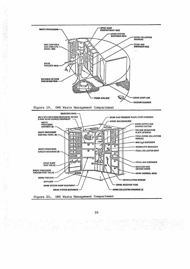
8/8/2019 MSFC Skylab Crew Systems Mission Evaluation
http://slidepdf.com/reader/full/msfc-skylab-crew-systems-mission-evaluation 50/397
WASTE PROCESSORS-_
WMC CONTROLSAND DISPLAYS _ [
(PANEL 800) 7
IURINE
FREEZER H810-'-_ _._
SPECIMEN RETURN j jPROVISIONS H005
k4_
/--UPINE DUMP
COMPARTMENT H822/ /---URINE SYSTEM
---- --/ DISPENSERH823 _-URINE COLLECTOR
_ J DRAWERS
7_ / y _FECAL BAG
_. __,,_ .DISPENSER03,,1..
_--TRASH AIRLOCK _URINE DUMP UNE
Figure 19. OWS Waste Management Compartment
SQUEEZER BAGS--_M074 SPECIMEN MASSMEASURING DEVICE
& WMCwAsTEMAINTENANCEOUIPMENT 7
PROCESSOR
CHAFABER(6) _ .---WASTE PROCESSOR ""
CONTROL PANEL (8)_ "_ _
WA EPROCESSORCIRCUIT BREAKERS(6)'-_ _ _tl_
URINE OUMP "/VENT VALVE
/ /URINE SYSTEM DUMPEQUI AENT ---/ /
URINE SYSTEM DISPENSER--/
URINE BAG PRESSUREPLATE (TEMPSTOWAGE)
URINE BAGSQUEEZERURINE SA_;PLE BAG
,_ _ CRIMPER CUTTER
/ _ VOLUME MEASURING
_[_J.,_ -_ PLATE(STOWED)_" |/'-" _ FECAL/URINE COLLECTION, 1 11 MOOULE
_ WMCH2O DISPENSER
_ _ --- --- -- -- - WASHCLOTHSQUEEZER
FECAL COLLECTOR SEAT
IF==_I]
I I'I'_ _ FECAL BAG DISPENSER
SQUEEZERBAOBEHIND DOOR)
_URINE DISPOSALBAGS
_'_-'- ARTICULATING MIRROR
URINE RECEIVER YOKE
URINE COLLECTOR DRAWERS (3)
Figure 20. OWS Waste Management Compartment
26
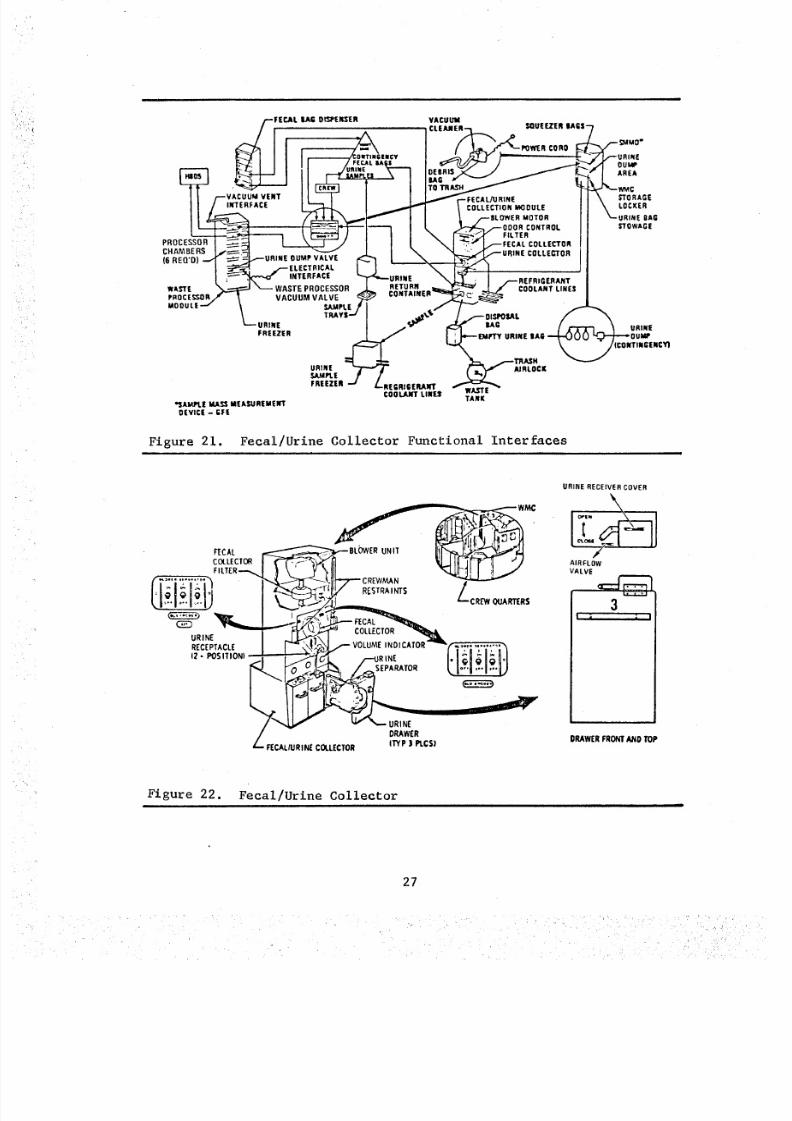
8/8/2019 MSFC Skylab Crew Systems Mission Evaluation
http://slidepdf.com/reader/full/msfc-skylab-crew-systems-mission-evaluation 51/397
PROCESSOR
CHAMBERS
( 6 R EQ 'D )
._ r'ALIAGOI_I=E_ER
VENT
INTERFACE
OUMP VALVE
,ECTRICAL
INTERFACE
WAS TE P RO CE SS OR
VACUUM VALVE
SJLMPLE
URINE
FREEZER
RETURN
VACUUM
COLLECTIONMOOULE
MOTOR
CONTROLFILTER
COLLECTOR
COOLANT LINES
*5AM._E Id_'_ MEASUREMEWTOiVlCi - GFE
TANK
Figure 21. Fecal/Urine Collector Functional Interfaces
ouiAe
AREA
STORAGE
LOCKER
gAG
STOWAGE
URINE
:ONTINGENCY)
/ _ v _ URINE
/ DRAWER
L _CALIURIP_ COLLECTOR I1_fP ) PLCS!
U RI NE R EC EI VE R COVER
AIRFLOW
VALVE
3I' i ' , i I
DRAWERFRONTAND TOP
Figure 22. Fecal/Urine Collector
27
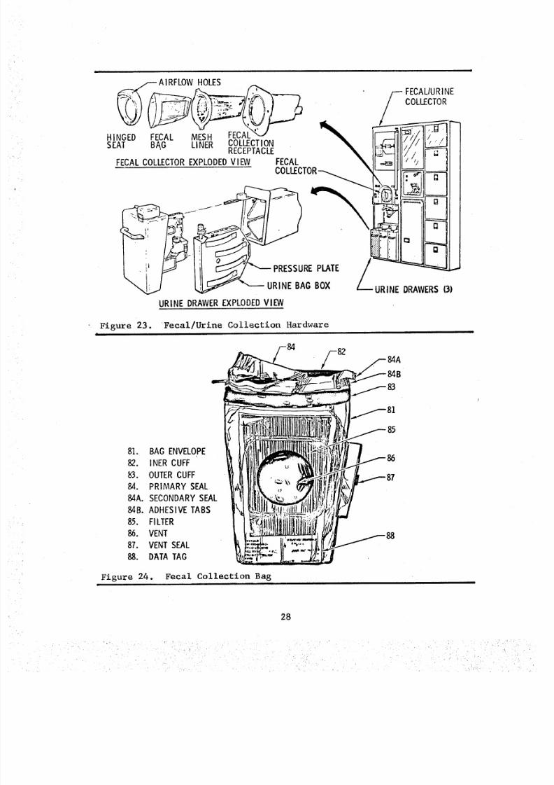
8/8/2019 MSFC Skylab Crew Systems Mission Evaluation
http://slidepdf.com/reader/full/msfc-skylab-crew-systems-mission-evaluation 52/397
i i
___AI FECALIURINE
RFLOWHOLES
y COLLECTOR
HINGED FECAL MESH FECAL
,_,=CA,OL,'C,OR,_XP,OD':DV,_ECALIP_lll_;_l_/
/_ tY__ __ iiJiiiFF':' I_/
Figure 23. Fecal/Urine Collection HardwareI
81. BAG ENVELOPE82. INER CUFF63. OUTERCUFF84. PRIMARY SEAL84A. SECONDARYSEAL84B. ADHESIVETABS85. FI LTER86. VENT87. VENT S EAL88. DATATAG
Figure 24. Fecal Collection Bag
28
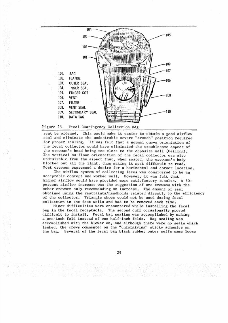
8/8/2019 MSFC Skylab Crew Systems Mission Evaluation
http://slidepdf.com/reader/full/msfc-skylab-crew-systems-mission-evaluation 53/397
104
105
101. BAG
102. FLANGE
103. OUTER SEAL
104. INNER SEAL
105. FINGER COT
106. VENT
107. FILTER
108. VENT SEAL
109. SECONDARY SEAL
110. DATA TAG
Figure 25. Fecal Contingency Collection Bag
seat be widened. This would make it easier to obtain a good airflow
seal and eliminate the undesirable severe "crouch" position required
for proper sealing. It was felt that a normal one-g orientation of
the fecal collector would have eliminated the troublesome aspect of
the crewman's head being too close to the opposite wall (Ceiling).The vertical as-flown orientation of the fecal collector was also
undesirable from the aspect that, when seated, the crewman's bodyblocked out all the light, thus making it most difficult to read.
Most crewmen expressed a desire for a horizontal and corner location.
The airflow system of collecting feces was considered to be an
acceptable concept and worked well. However, it was felt that
higher airflow would have provided more satisfactory results. A 50-
percent airflow increase was the suggestion of one crewman with the
other crewmen only recommending an increase. The amount of seal
obtained using the restraints/handholds related directly to the efficiency
of the collector. Triangle shoes could not be used during fecal
collection in the foot wells and had to be removed each time.
Minor difficulties were encountered while installing the fecal
bag in the fecal receptacle. The second cuff occasionally proved
difficult to install. Fecal bag sealing was accomplished by making
a one-inch fold instead of one half-inch folds. Bag sealing was
accomplished with the blower on, and although there were no seals which
leaked, the crews commented on the "unforgiving" sticky adhesive on
the bag. Several of the fecal bag black rubber outer cuffs came loose
29
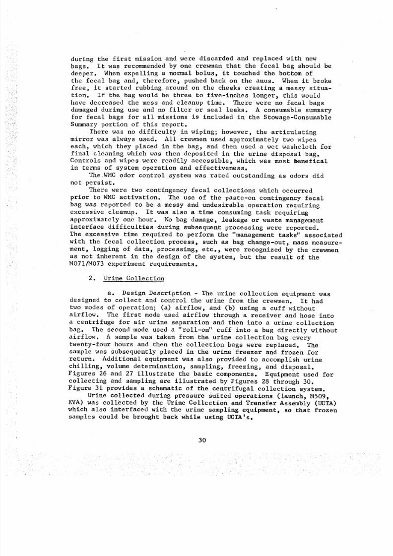
8/8/2019 MSFC Skylab Crew Systems Mission Evaluation
http://slidepdf.com/reader/full/msfc-skylab-crew-systems-mission-evaluation 54/397
during the first mission and were discarded and replaced with newbags. It was recommendedby one crewmanthat the fecal bag should bedeeper. Whenexpelling a normal bolus, it touched the bottom ofthe fecal bag and, therefore, pushed back on the anus. Whenit broke
free, it started rubbing around on the cheeks creating a messy situa-tion. If the bag would be three to five-inches longer, this wouldhave decreased the messand cleanup time. There were no fecal bagsdamagedduring use and no filter or seal leaks. A consumablesummaryfor fecal bags for all missions is included in the Stowage-ConsumableSummaryportion of this report.
There was no difficulty in wiping; however, the articulatingmirror was always used. All crewmenused approximately two wipeseach, which they placed in the bag, and then used a wet washcloth forfinal cleaning which was then deposited in the urine disposal bag.Controls and wipes were readily accessible, which was most benefical
in terms of system operation and effectiveness.
The WMC odor control system was rated outstanding as odors did
not persist.There were two contingency fecal collections which occurred
prior to WMC activation. The use of the paste-on contingency fecal
bag was reported to be a messy and undesirable operation requiring
excessive cleanup. It was also a _time consuming task requiring
approximately one hour. No bag damage, leakage or waste management
interface difficulties during subsequent processing were reported.
The excessive time required to perform the "management tasks" associated
with the fecal collection process, such as bag change-out, mass measure-
ment, logging of data, processing, etc., were recognized by the crewmen
as not inherent in the design of the system, but the result of theM071/M073 experiment requirements.
2. Urine Collection
a. Design Description - The urine collection equipment wasdesigned to collect and control the urine from the crewmen. It had
two modes of operation; (a) airflow, and (b) using a cuff without
airflow. The first mode used airflow through a receiver and hose into
a centrifuge for air urine separation and then into a urine collection
bag. The second mode used a "roll-o_' cuff into a bag directly without
airflow. A sample was taken from the urine collection bag every
twenty-four hours and then the collection bags were replaced. The
sample was subsequently placed in the urine freezer and frozen for
return. Additional equipment was also provided to accomplish urine
chilling, volume determination, sampling, freezing, and disposal.Figures 26 and 27 illustrate the basic components. Equipment used for
collecting and sampling are illustrated by Figures 28 through 30.
Figure 31 provides a schematic of the centrifugal collection system.
Urine collected during pressure suited operations (launch, M509,EVA) was collected by the Urine Collection and Transfer Assembly (UCTA)
which also interfaced with the urine sampling equipment, so that frozen
samples could be brought back while using UCTA's.
30
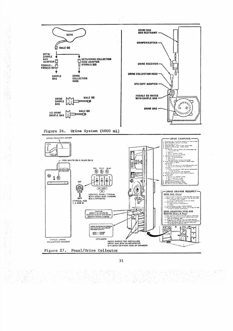
8/8/2019 MSFC Skylab Crew Systems Mission Evaluation
http://slidepdf.com/reader/full/msfc-skylab-crew-systems-mission-evaluation 55/397
UCTA]SAMPLE8AG I"ziADAPTOR
FEMALE- I'1FEMALE ODtcJ
SAMPLEBAG
i 4,
[_ UCTA]URINE COLLECTIONHOSE AOAPTOR(FEMALE DO)
URINECOLLECTIONHOSE
URINE MALE OD
SAMPLEBAG
1/2 URINE [__OOAMPLE BAG
URINE BAGBOX RESTRAINT
URINE
URINE COLLECTION HOSE--_
\UTS CUFF ADAPTER
FEMALE OD MATES ._
WITH SAMPLE BAG--'_ I1_, %
URINE BAG _
Figure 26. Urine System (4000 ml)
URINE RECEIVER COVER
HITE ON 2, BLUE ON 3)
CONTROL PANEL TYPICALBOTH SIDES [BUS ! SHOWN
OFF BUS 20PPOSITEI
(TYPICAL FOR
1, 2 AND 3)
ZYPICAL URINE
COLLECTION ORAWER
Figure 27.m
"I._
I
, i
INSPECT TO INSURE NOFOREION OBJECTS A nE I NS ID E
DRAWER _EEORE CLO_;ING J _l
U R+ NE S EPAR ATOR FOWENO UTL ETS O N C EI LI NG OFD RAWE R C AV IT Y:
6 0"S 1 - - F R ON TguS Z - REA_
( 3 P LA CE S(
INDEX MARKS FOR INSTALLING
URINE BAG BOX ON SEPARATOR
(2 PLACES ON RIGHT SIDE O F D RA WE R)
Fecal/Urine Collector
f
URINE SAMPLING
. . .. .. .. _ ,g . .. .. .. ,
":'";L'. ..........................
_.,... ¢*,.., cu.,.
• _ ,, •. ., . _ ., ,, , .= to.
..* ° ...........
_URINE DRA_/ER RI:_;ul;Pt.Y _'-
URINE BAG (Doily)
• c.,, .• .......... c,o.
URINE COLLECTION HOSE AND
RECEIVER (Every 8 Days)
,2" ;' " 7'":,'..7.:".................' _;,,'._':,_ ,_,:.o ............. I -I ....
31
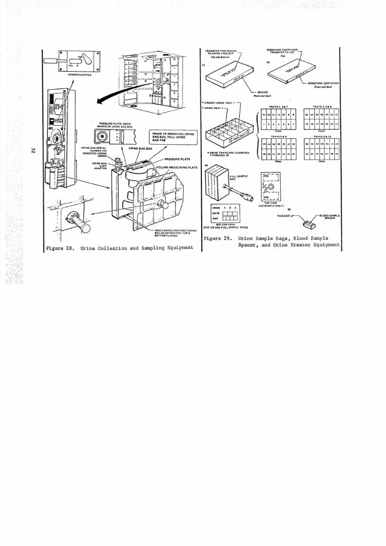
8/8/2019 MSFC Skylab Crew Systems Mission Evaluation
http://slidepdf.com/reader/full/msfc-skylab-crew-systems-mission-evaluation 56/397
, ' : ::::_::j_:/i:(i.,!,:::+:ii:i/!:/ii!+L::iiii_i:::
i:i
i_ ¸
•
+
_iii:_i_!__i
:_:_
O OO EC AN E C ON TA IN ER
TRAYS 1.3& 7 TRAYS 2, 4 & 8
Fronf Front
TRAYS 5 & 9 TRAYS 6 & I0
11
1110 31 32 3:1 34 315 43 4+1 45 46 41 48 49
Fron_ Front
[F_-- q[I_ _ _ _.J
TO P V IE W
It 2 SAMPLE ONLY|
151
THIS SIDE UP --%+ ]---B L OO D S AM PLE
SPACER .
Urine Sample Bags, Blood Sample
Spacer_ and Urine Freezer Equipment
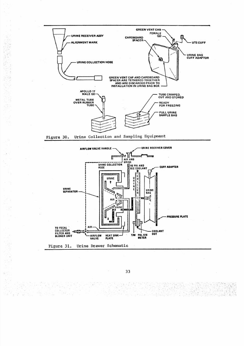
8/8/2019 MSFC Skylab Crew Systems Mission Evaluation
http://slidepdf.com/reader/full/msfc-skylab-crew-systems-mission-evaluation 57/397
i i.
Figure 30.
i
GREENENT,'A.R,NEECEIVER'? _EMALE--_CARD.OARD O_--_ __ 0_
_CE_-__ "_-UTscv_F
ALIGNMENT MARK
__ I\ \ 1 I II _-URINE BAG
URINE COLLECTI ON HOSE
_r I---I GREENENTAP NDCARDBOARO_r"_,!ll' J SPACER ARE TETHERED TOGETHER _
AND ARE DISCARDED PRIOR TO tINSTALLATION IN URINE BAG BOX _.,_.J
APOLLO 17
/--- TUBE CRIMPED.
MALE QD--_ / CUT AND STOWED
METAL TUBE / _-- READY
OVERRUBBERTu . , / / FORFREEZING_ , "'_'_.J r-- FULL URINE
S'MPLERAG
Urine Collection and Sampling Equipmenti i i i i
TO FECALCOLLECTORFILTER ANDBLOWER UMIT
AIRFLOW VALVE HANDLE_ f f--" URINE RECEIVER COVER
-- -J URIBE
IB_u"!"EI II
AIRFLOW HEAT SINK.VALVE PLATE
T/M
URINE
SEPARATOR--_,,,,.,.,,,..._.
CUFF ADAPTER
L,_L_E_ URINE_ BAG
_ f
• _ PRESSUREPLATE
COOLANT
PNL 616 OUTMETER
_igure 31. Urine Drawer Sch_atic
33
8/8/2019 MSFC Skylab Crew Systems Mission Evaluation
http://slidepdf.com/reader/full/msfc-skylab-crew-systems-mission-evaluation 58/397
Each crewman had a separate urine collection system contained in
one of three drawers mounted in the fecal/urine collector. A 120 ml -
130 ml sample was drawn from each crewman's daily "pooled" urine
collection using the following procedure. The urine bag was attached
to the front of the upper fecal/urine collector door and a sample
bag connected to the urine bag with an interconnecting hose attached
to the sample bag. The sample bag was then placed in a crimper/cutter
mechanism and filled by applying pressure to the urine bag with
squeezer handles. The interconnecting hose was then cut and crimpedwith the crimper/cutter. The urine sample was then frozen in the
urine freezer and maintained below a maximum specified temperatureuntil returned to earth for bio-medical analysis.
Expendable equipment, used to collect and sample urine, included:
urine collection bags, sample bags, receivers, urine collection UCTA/
sample bag adaptors, UCTA/urine collection hose adaptors, hoses and
roll-on cuffs. Table 5 lists the total equipment launched, excludingadditional resupply items, which are included in the Stowage-Consumable
Summary section.
b. Post Mission Assessment - The centrifugal system was
the primary method of urine collection used by all crews, with occa-
sional use of the roll-on cuff and UCTA'S, and all equipment operated
satisfactorily. Using a blower/separator system, which eliminated the
need for cuffs, makes the act of urination a natural act. The bag
system was considered good assuming the procedure called for poolingthe urine all day, then dumping. Several of the crewmen even urinated
while "floating free" and "upside down', using no restraints, and
reported satisfactory results. The crewmen considered one foot restraint
adequate for stand-up urination. As with the fecal collection, therewere both favorable and unfavorable comments in the assessment of the
urine collection system. These are summarized in the followingparagraphs.
The system remained surprisingly clean and relatively free from
unpleasant odors throughout all the missions. The third crew did not
perform the final microbiological cleaning and changeout of contaminated
areas and equipment, but did swab some areas to obtain bacteria
samples to determine which type lives with crewmen in the zero-g
environment. Near the end of the third mission, there was a report ofan ammonia odor emminating from the collection module. The odor was
apparent when the blower was operating, indicating a failure of the
odor control filter. The odor control filter, designed for 28 daysof operation, had been operating for 51 days• at the time the crew
reported the odor. It was recommended that the filter and blower,if necessary, be replaced with spares available on board. The odor was
reported to have increased in intensity during the last week of the
mission with the blower itself, not the filter, appearing to be the
source. No further conversations with the crew regarding this problem
were found, consequently, it is not known if these units were replaced.
34
8/8/2019 MSFC Skylab Crew Systems Mission Evaluation
http://slidepdf.com/reader/full/msfc-skylab-crew-systems-mission-evaluation 59/397
8/8/2019 MSFC Skylab Crew Systems Mission Evaluation
http://slidepdf.com/reader/full/msfc-skylab-crew-systems-mission-evaluation 60/397
was reluctant to slam the drawer and thereafter applied a force
slowly which adequately closed the door. It was reported once, that
two separators were "o_' simultaneously and the resulting current did
not open the circuit breaker. Operation of the urine collector during
the second mission was normal through mission day 59, when, on
deactivation of Urine Drawer No. 3 it was found that the suction linehad debonded and floated away from the suction line. The seal was
captured, taped to the collector face, and photographed. Examination
of the returned photograph pin-pointed the failure and a repair kit
was fabricated for the third mission crew to remedy the problem.
Figure 32 illustrates the problem and the repair technique used by
the third crew successfully. During the latter part of the third
mission, the crew reported that urine crystals began forming over all
separators at the juncture between the two halves of the separator.
The crystals were removed but reformed. It appeared to be the result
of a very gradual time-constant process that was progressive over the
entire mission. This phenomenon was observed occurring on all separa-tors but did not seriously impair urine collection activities.
There was no major spillage or breakage of urine or sample bags,
although an occasional minor leaked was noted and a few bags broke
during the third mission. The loose urine was readily cleaned up and
created no serious problem. Additional urine droplets were cleaned
up as required at the boot interface to the urine separator. Occasion-
ally, the urine hoses were pinched when caught behind the separator
motor. This was corrected by insuring that the urine hose was not in
a position to become pinched prior to closing the drawer. The crews
changed hoses and receivers on a regular basis, varying from one week
to two weeks. No difficulty was experienced installing a new urine
bag in the urine bag box and on the separator. During the third
mission, in order to conserve the limited supply, the crew started
using urine bags for more than one day due to the extended missionduration. The urine drawers were considered to be in an inaccessible
area and difficult to properly inspect because the lighting wasinadequate. The connectors were all hidden well back inside the
drawers; however, one crewman stated that he learned to mate and unmate
the connectors by feel during training. One grounding strap on the
urine drawer kept separating frequently, even during normal removaland reinstallation.
The no_ e level of the separators was not disturbing during use;
however, when used during sleep periods, the sleeping crewmen were on
occasions, awakened by the separator noise. This was mainly attributed
to the relatively low noise levels in the spacecraft which made anyother noises seem loud and disturbing and should be a consideration
in future designs.
The condensation in the urine drawer chillers was minimal and
confined to the chiller plates. This condensation was wiped daily asa part of bag change-out. The average temperature for the three
chillers for the duration of the mission was 45°F. Early in the missian,
36
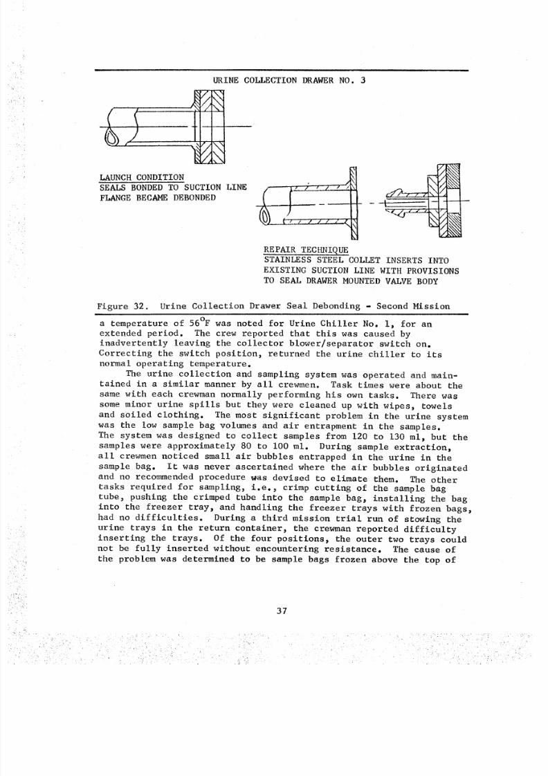
8/8/2019 MSFC Skylab Crew Systems Mission Evaluation
http://slidepdf.com/reader/full/msfc-skylab-crew-systems-mission-evaluation 61/397
URINECOLLECTIONRAWERO. 3
i
LAUNCH CONDITION
SEALS BONDED TO SUCTION LINE
FLANGE BECAME DEBONDED
"_' I / I I /
REPAIR TECHNIQUE
STAINLESS STEEL COLLET INSERTS INTO
EXISTING SUCTION LINE WITH PROVISIONS
TO SEAL DRAWER MOUNTED VALVE BODY
Figure 32. Urine Collection Drawer Seal Debonding - Second Missioni
a temperature of 56°F was noted for Urine Chiller No. i, for an
extended period. The crew reported that this was caused byinadvertently leaving the collector blower/separator switch on.
Correcting the switch position, returned the urine chiller to its
normal operating temperature.
The urine collection and sampling system was operated and main-
tained in a similar manner by all crewmen. Task times were about thesame with each crewman normally performing his own tasks. There was
some minor urine spills but they were cleaned up with wipes, towels
and soiled clothing. The most significant problem in the urine system
was the low sample bag volumes and air entrapment in the samples.
The system was designed to collect samples from 120 to 130 ml, but the
samples were approximately 80 to i00 ml. During sample extraction,
all crewmen noticed small air bubbles entrapped in the urine in the
sample bag. It was never ascertained where the air bubbles originated
and no recommended procedure was devised to elimate them. The other
tasks required for sampling, i.e., crimp cutting of the sample bag
tube, pushing the crimped tube into the sample bag, installing the bag
into the freezer tray, and handling the freezer trays with frozen bags,had no difficulties. During a third mission trial run of stowing the
urine trays in the return container, the crewman reported difficulty
inserting the trays. Of the four positions, the outer two trays couldnot be fully inserted without encountering resistance. The cause of
the problem was determined to be sample bags frozen above the top of
37
8/8/2019 MSFC Skylab Crew Systems Mission Evaluation
http://slidepdf.com/reader/full/msfc-skylab-crew-systems-mission-evaluation 62/397
_
the tray. Removal of all the cardboard spacers from the returncontainer still did not provide sufficient space for the trays. In
further conversations, the crewman indicated he felt he could force
the trays into the container adequately. Several of the samples were
decapitated, but it was felt that since they would remain frozen they
would not loose their integrity.
The daily urine volume (mechanical versus LiCI analysis) for
each crewman during the first and second mission is plotted in Figures
33 and 34 respectively. The daily urine sample size for each crew-
man during the first and second mission is plotted in Figures 35 and
36 respectively. Daily urine volume and sample size data was notavailable for the third mission crewmen. The urine volumes for each
of the crewmen as determined by the analysis for lithium concentra-
tion in the returned samples are provided by Tables 6, 7 and 8. Post
mission analyses revealed that the sample volumes were lower than the
planned 120 ml and urine sampling data had a minor learning curve at
the start of each mission for each crewman.
The urine bags were evacuated through the urine dump system, priorto the daily installation in the urine drawers to void the bags of
air. During urine bag evacuation, one inlet check valve "squealed",
indicating air passing through the check valve. The bag was disposed
and subsequently the general practice by the crew was to use the
inlet boot plug. During the third mission, urine bag "swelling" wasencountered while cycling the trash airlock and the three full urine
bags were dumped into the waste tank through the urine dump system.On several occasions during urine dump, the crew had difficulties
with undissolved boric acid tablets in the urine bags. On another
occasion the urine dump system became clogged, but was later unplugged.
There was no report of leakage, spillage, or contamination in the dump
compartment resulting from use of the urine dump system.
There was a lack of provisions for securing items, during the
sampling and urine bag changing process, which contributed to ineffi-
cient urine system management and loose items frequently floatingwithin and out of the WMC.
A way to wipe off the penis after urination is need for future
design iterations. It was felt there could be a slight airflow at a
certain point on the lid of the collection cup that would blow the
urine into the cup, thus eliminating all the hassle. Also, because
of the low airflow, when a crewman urinated an additional volume,the centrifuge stopped up, thus causing backflow.
As in fecal collection, the amount of time required for the
various management tasks associated with urine collection, i.e.,
sampling, measuring, bag replacement, etc., must be reduced in thefuture.
3. Waste Processor
a. Design Description - The waste processor was,designedto process crew feces and vomit bags, PGA suit desiccants, and filmvault desiccants. The processor was capable of using heat or space
vacuum to sublimate water and "dry" the material.
38
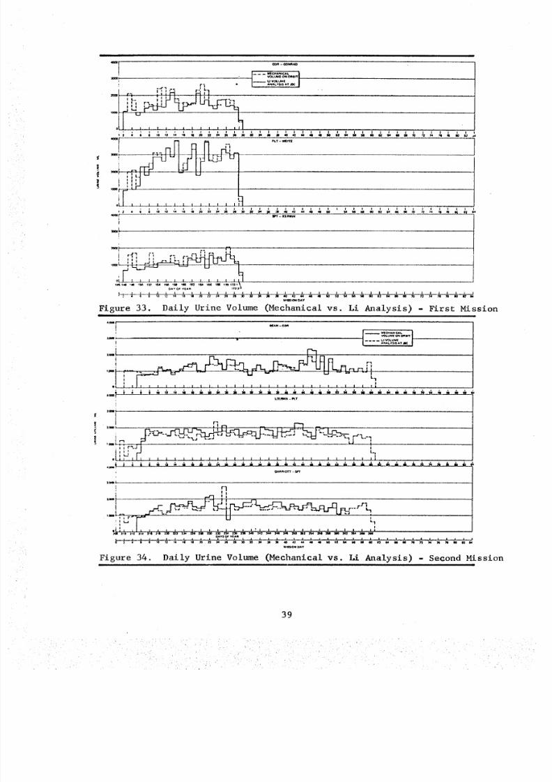
8/8/2019 MSFC Skylab Crew Systems Mission Evaluation
http://slidepdf.com/reader/full/msfc-skylab-crew-systems-mission-evaluation 63/397
|
z_el
,ee_
i I ,-_ r-, "1r_ I r'l I-I iI ' • I i _ I I .L. I -'_
i I i i I
,
I...........OLUUE ONo_err-- u V (XUUE
ANALV._SAT
o_ri_l L i L I i j I i i , i i_j2
_ KI_R_TN
. .. . r'_ r_ '
I r,_ I _% _- ,_ ' _ Pr_ Ii I i | i i !I I t l N_ I
M_IION O_Y
Figure 33. Daily Urine Volume (Mechanical vs. Li Analysis) - First Mission
._r
; r]1 I
t_
r_ _ _ E}_ _ _n j._'l_
,_,.I _ _ "_:" _a •.,, r-j , F" U - -- u _ ,
III I I : I I I I I I I I I I I | I I I
Figure 34. Daily Urine Volume (Mechanical vs. Li Analysis) l Second Mission
39
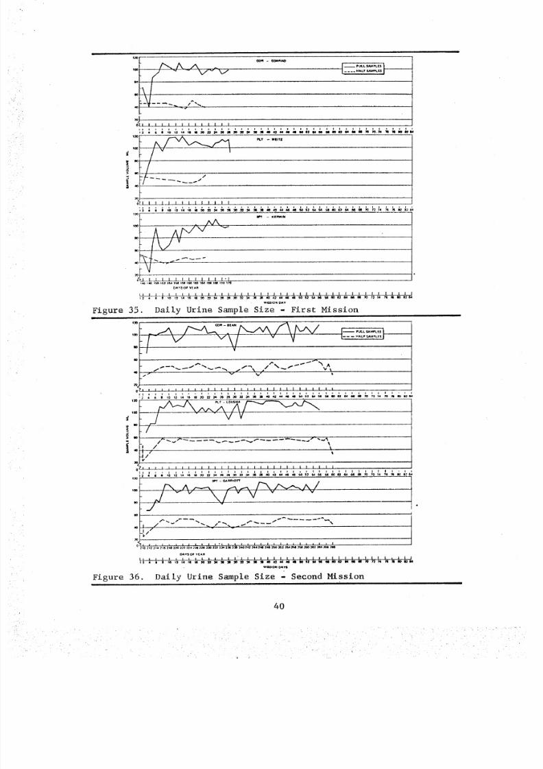
8/8/2019 MSFC Skylab Crew Systems Mission Evaluation
http://slidepdf.com/reader/full/msfc-skylab-crew-systems-mission-evaluation 64/397
JL
I-----:.,.'T;_ I------
_llllllllll[l|
Figure 35.
:.LILJ_LLLJ--L-I l " I
U_tON OAY
Daily Urine Sample Size - First Mission
+"
i.
Figure 36,
I............ ---
o I I l l I I I I i I I I I I I I I I I I I 1 1 I I I l I I
.... ,_,:,;,;_;;'_o_'_.;66"'6'_: ;,;._,;o;,_'_.;0;._+_',.;o6.:2 , 6 e Io
-/
I // I
$/'I I I I l I I I I I ] I I I I I I I I I I I I l I I I f I l
I I I I I l I I i I i I I I i I I I,_ I I I 1 I • i i l , l l
O AY S O _ Y tA _
_UI :t I I;_ r.l _+i m _a
_tOm OAYII
Daily Urine Sampl.e Size - Second Mission
40
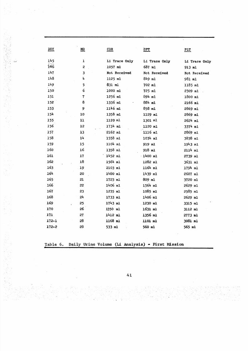
8/8/2019 MSFC Skylab Crew Systems Mission Evaluation
http://slidepdf.com/reader/full/msfc-skylab-crew-systems-mission-evaluation 65/397
DOY MD CD8 "SPT PLT
11,5
lh7
lh8
lh9
15o
151
152
153
15k
155
156
157
158
159
16o
161
162
163
16h
165
166
167
168
169
17o
171
172-1
172-2
i Li Trace Only Li Trace Only Li Trace Only
2 1057 ml 687 ml 913 ml
3 Not Received Not Received Not Received
4 1125 ml 849 ml 981 ml
5 831 ml 702 ml 1185 ml
6 i000 ml 725 ml 2309 ml
7 1256 ml 894 ml 1800ml
8 1336 ml 884 ml 2166 ml
9 llh6ml 858 ml 2869 ml
i0 1358 ml i129 ml 2869 mlIi l120ml 1301 ml 2624 ml
12 1734 ml 1120 ml 3374 ml
13 2162 ml 1116 ml 2869 ml
lh 1558 ml i034 ml 3838 ml
15 llOh ml 919 ml 1943 ml
16 1358 ml 918 ml 2114 ml
17 i452 ml -lhO0 ml 2739 ml
18 1564 ml 1282 ml 3631 ml
19 2103 ml 1164 ml 1794 ml
20 i480 ml 1439 ml 2607 ml
21 1723 ml 809 ml 3720 ml
22 1406 ml 1564 ml 2629 ml
23 1235 ml i085 ml 2585 ml
24 1733mi lh06 ml 2629mi
25 1743 ml 1230 ml 3315 ml
26 1350 ml 1631 all 3112 all
27 lhl2ml 1356 ml 2773 ml
28 1168 ml Ii01 ml 3081 ml
28 533 ml 560 ml 565 ml
Table 6. Daily Urine Volume (Li Analysis) - First Mission
41
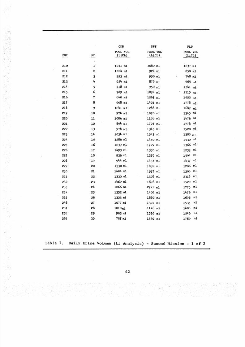
8/8/2019 MSFC Skylab Crew Systems Mission Evaluation
http://slidepdf.com/reader/full/msfc-skylab-crew-systems-mission-evaluation 66/397
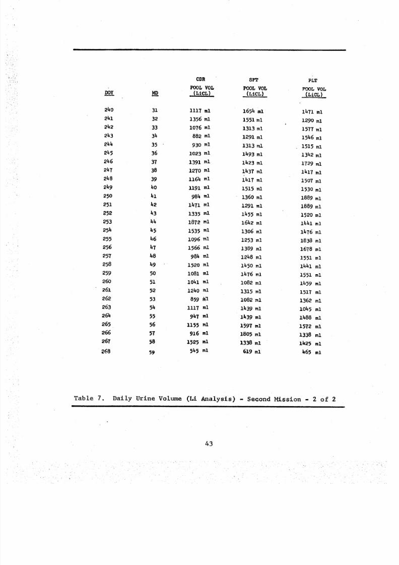
8/8/2019 MSFC Skylab Crew Systems Mission Evaluation
http://slidepdf.com/reader/full/msfc-skylab-crew-systems-mission-evaluation 67/397
Do_/Y
CDR SPT PIT
Pool vor Pooc vor _oc vor.(LiCL) • . (LiCL) (LiCL)
240 31 1117 ml 1654 ml 1471 ml
241 32 1356ml 1551 ml 1290miJ
242 33 1076 ml 1313 ml 1577 ml
243 34 882 ml 1291 ml 1546 ml
244 35 " 930 ml 1313mi 1515mi
245 36 1023 ml 1493 ml 1342 ml
246 37 1391 ml 1423 ml 1729 ml
2_7 38 1270 ml i_37 ml 1417 ml
248 39 1164 ml 1417 ml 1507ml
249 40 1191 ml 1515 ml 1530 ml
250 hl 984 ml 1360 ml 1889 ml
251 42 1_71 ml 1291 ml 1889 ml
252 43 1335 ml 1455 ml 1520 ml
253 4_ 1872 ml 1642 ml 1441 ml
25_ 45 1535 ml 1306ml I_76ml
255 46 1096 ml 1253 ml 1838 ml
256 47 1566 ml 1389 ml 1678 ml
257 _8 984 ml 1248 ml 1551 ml
258 49 ' 1520 ml 1450 ml i441 ml
259 50 1081 m l i476 ml 1551 ml
260 51 1041 ml 1082 ml I_59 ml
261 52 1240 ml 1315 ml 1517 ml
262 53 859 _I 1082 ml 1362 ml
263 5_ 1117 ml I439 ml I045 ml
26_ 55 9_7 ml I_39 ml I_88 ml
265 56 1155 ml 1597 ml 1572 ml
266 57 916 ml 1805 ml 1338 ml
267 58 I_25 ml 1338 ml I_25 ml
268 59 545 ml 619 ml 465 ml
Table 7. Daily Urine Volume (Li Analysis) - Second Mission - 2 of 2| t i
43
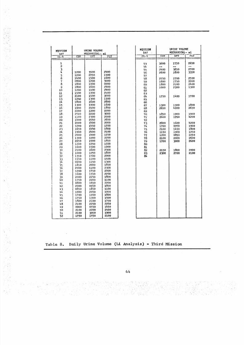
8/8/2019 MSFC Skylab Crew Systems Mission Evaluation
http://slidepdf.com/reader/full/msfc-skylab-crew-systems-mission-evaluation 68/397
MISSION URINE VOLUMEDAY MECI!AtIICAI,-ml
SI,-h CDR SPT PLT ,
12
3b 12oo 35oo 2boo
5 12oo 2750 15oo6 iboo 15oo 160o7 o8oo 12o0 30008 18oo 17oo 09009 18oo 16oo 2boo
10 1200 1100 2boo11 1500 1700 210012 2100 15o0 300013 12o,0 13o0 1500lh 1800 1600 280015 1300 1700 160016 1900 2100 185017 2200 1200 2200
18- 2500 2200 300019 iiO0 2300 200020 lhOO 2950 260021 2200 lhoo 200022 1200 lhSO 170023 1650 lhSO 18002h 190o 2boo 210025 2000 1bOO 125026 1300 1200 220027 2250 1500 185o28 12oo 125o 15oo29 1600 1500 1900
30 2100 1600 230031 IO00 1250 18OO32 1350 1700 2000
33 1550 Ii00 15003h 0900 1150 130035 1850 2OOO 185o36 2ooo ilOO 2300
37 12oo 1750 200038 1600 1550 225039 2000 2250 1800hO 1750 2200 1100hi 0800 1650 2200
h2 2000 0950 1850
h3 0850 1850 IIO0bh 1900 2050 1950b5 1700 1200 1800h6 1750 1350 1500h7 1800 2100 1750
h8 2100 2250 2250h9 0900 0750 lhSO50 2100 2200 250051 2100 3050 190052 175o 175o 21oo
MIGBIONDAY
SL-h
535155565758596o61626361,6566
6768
69
7O7172737h7516777879808182
838b
U_INE VOL_4EM EC RAN IC AL- m l
CDR , SPT [ PLT
3600 175o 2650
21,00 3850 27002600 1800 3350
2750 17o0 250016oo 1750 200018oo 2100 21,001000 2300 1300
175o lhO0 1700
1300 1300 18002650 _ooo 2650
1850 1900 19o02600 1950 h2oo
2800 1600 1,200
17o0 0950 19002100 11,50 18o0115o 19oo 125012oo 0850 22502100 2000 26001700 3000 2600
2150 1800 20002300 2700 2100
Table 8. Daily Urine Volume (Li Analysis) - Third Mission
44
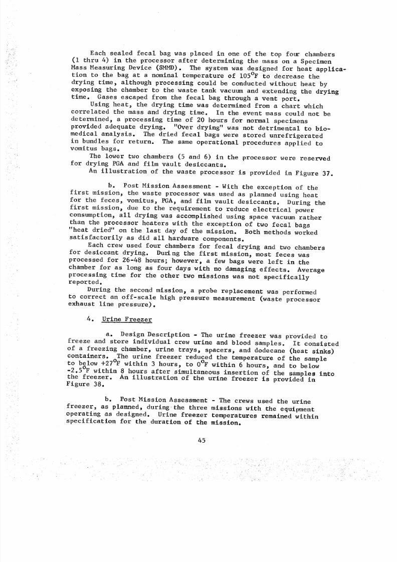
8/8/2019 MSFC Skylab Crew Systems Mission Evaluation
http://slidepdf.com/reader/full/msfc-skylab-crew-systems-mission-evaluation 69/397
Each sealed fecal bag was placed in one of the top four chambers
(I thru 4) in the processor after determining the mass on a Specimen
Mass Measuring Device (SMMD). The system was designed for heat applica-
tion to the bag at a nominal temperature of 105°F to decrease the
drying time, although processing could be conducted without heat by
exposing the chamber to the waste tank vacuum and extending the dryingtime. Gases escaped from the fecal bag through a vent port.
Using heat, the drying time was determined from a chart which
correlated the mass and drying time. In the event mass could not be
determined, a processing time of 20 hours for normal specimens
provided adequate drying. "Over drying" was not detrimental to bio-
medical analysis. The dried fecal bags were stored unrefrigerated
in bundles for return. The same operational procedures applied tovomitus bags.
The lower two chambers (5 and 6) in the processor were reservedfor drying PGA and film vault desiccants.
An illustration of the waste processor is provided in Figure 37.
b. Post Mission Assessment - With the exception of the
first mission, the waste processor was used as planned using heat
for the feces, vomitus, PGA, and film vault desiccants. During the
first mission, due to the requirement to reduce electrical power
consumption, all drying was accomplished using space vacuum rather
than the processor heaters with the exception of two fecal bags
"heat dried" on the last day of the mission. Both methods worked
satisfactorily as did all hardware components.
Each crew used four chambers for fecal drying and two chambers
for desiccant drying. Dugng the first mission, most feces was
processed for 26-48 hours; however, a few bags were left in the
chamber for as long as four days with no damaging effects. Average
processing time for the other two missions was not specificallyreported.
During the second mission, a probe replacement was performed
to correct an off-scale high pressure measurement (waste processorexhaust line pressure).
4. Urine Freezer
a. Design Description - The urine freezer was provided to
freeze and store individual crew urine and blood samples. It consisted
of a freezing chamber, urine trays, spacers, and dodecane (heat sinks)
containers. The urine freezer reduced the temperature of the sampleto below +27°F within 3 hours, to 0°F within 6 hours, and to below
-2.5°F within 8 hours after simultaneous insertion of the samples intothe freezer. An illustration of the urine freezer is provided inFigure 38.
b. Post Mission Assessment - The crews used the urine
freezer, as planned, duringthe three missions with the equipmentoperating as designed. Urine freezer temperatures remained within
specification for the duration of the mission.
45
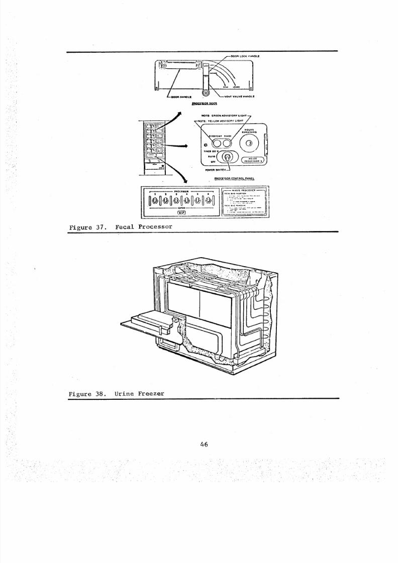
8/8/2019 MSFC Skylab Crew Systems Mission Evaluation
http://slidepdf.com/reader/full/msfc-skylab-crew-systems-mission-evaluation 70/397
Figure 37.
r.--OOOA HANOL! . WENT VALVI_ _A_4DLI
DPIN-
C_8
, _i_"-:.i_&8:-_'- If
<.:!_e.:: ... iFecal Processor
I
Figure 38. Urine Freezer
46
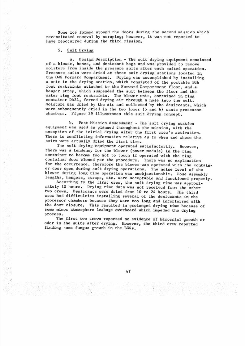
8/8/2019 MSFC Skylab Crew Systems Mission Evaluation
http://slidepdf.com/reader/full/msfc-skylab-crew-systems-mission-evaluation 71/397
Some ice formed around the doors during the second mission which
necessitated removal by scraping; however, it was not reported tohave reoccurred during the third mission.
5. Suit Drying
a. Design Description - The suit drying equipment consistedof a blower, hoses, and desiccant bags and was provided to remove
moisture from inside the pressure suits after each suited operation.
Pressure suits were dried at three suit drying stations located in
the OWS Forward Compartment. Drying was accomplished by installing
a suit in the drying station, which consisted of the portable PGA
foot restraints attached to the Forward Compartment floor, and ahanger strap, which suspended the suit between the floor and the
water ring foot restraints. The blower unit, contained in ringcontainer D424, forced drying air through a hose into the suit.
Moisture was dried by the air and collected by the desiccants, which
were subsequently dried in the two lower (5 and 6) waste processor
chambers. Figure 39 illustrates this suit drying concept.
b. Post Mission Assessment - The suit drying station
equipment was used as planned throughout the mission, with the
exception of the initial drying after the first crew's activation.
There is conflicting information relative as to when and where the
suits were actually dried the first time.
The suit drying equipment operated satisfactorily. However,
there was a tendency for the blower (power module) in the ring
container to become too hot to touch if operated with the ring
container door closed per the procedure. There was no explanation
for the occurrence, therefore the blower was operated with the contain-er door open during suit drying operations. The noise level of the
blower during long time operation was unobjectionable. Hose assembly
lengths, hangers, straps, etc. were acceptable and functioned properly.
According to the first crew, the suit drying time was approxi-mately i0 hours. Drying time data was not received from the other
two crews. Desiccants were dried from i0 to 24 hours. The third
crew had difficulties installing several of the desiccants in the
processor chambers because they were too long and interferred with
the door closure. This resulted in prolonged drying time because of
some minor atmosphere leakage overboard which impeded the dryingprocess.
The first two crews reported no evidence of bacterial growth or
odor in the suits after drying. However, the third crew reported
finding some fungus growth in the LCGs.
47
8/8/2019 MSFC Skylab Crew Systems Mission Evaluation
http://slidepdf.com/reader/full/msfc-skylab-crew-systems-mission-evaluation 72/397
FILTER ASSEMBLY\
\
DOME LOCKED 0424JLE
]LDASSEMBLY
GAS CONNECTOR
WATER RINGFOOT
POWER
HANGERSTRAP
Figure 39. Suit Drying Station
PGAFOOTRESTRAINT
48
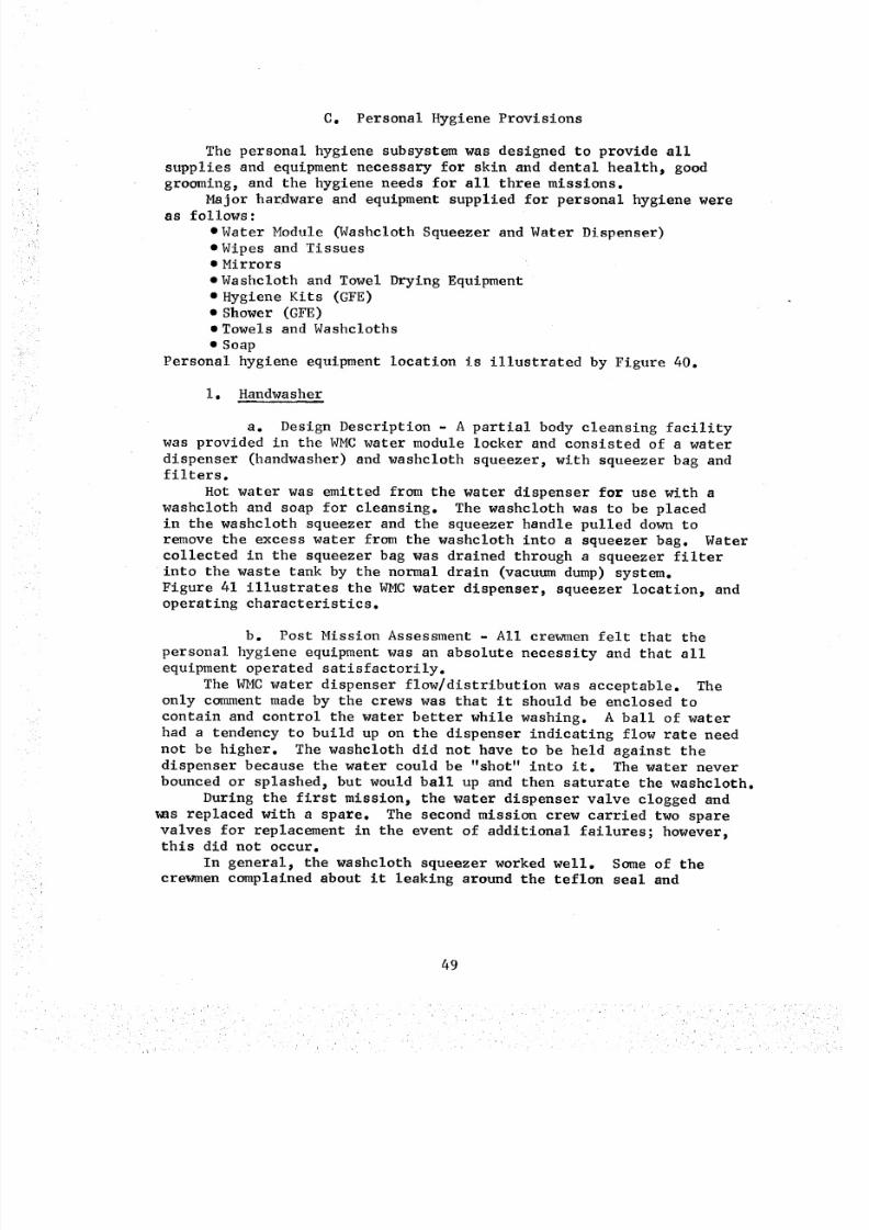
8/8/2019 MSFC Skylab Crew Systems Mission Evaluation
http://slidepdf.com/reader/full/msfc-skylab-crew-systems-mission-evaluation 73/397
C. Personal Hygiene Provisions
The personal hygiene subsystem was designed to provide all
supplies and equipment necessary for skin and dental health, good
grooming, and the hygiene needs for all three missions.
Major hardware and equipment supplied for personal hygiene wereas follows:
• Water Module _Washcloth Squeezer and Water Dispenser)
• Wipes and Tissues• Mirrors
• Washcloth and Towel Drying Equipment
e Hygiene Kits (GFE)
• Shower (GFE)
• Towels and Washcloths
• Soap
Personal hygiene equipment location is illustrated by Figure 40.
i. Handwasher
a. Design Description - A partial body cleansing facility
was provided in the WMC water module locker and consisted of a water
dispenser (handwasher) and washcloth squeezer, with squeezer bag andfilters.
Hot water was emitted from the water dispenser for use with a
washcloth and soap for cleansing. The washcloth was to be placed
in the washcloth squeezer and the squeezer handle pulled down to
remove the excess water from the washcloth into a squeezer bag. Water
collected in the squeezer bag was drained through a squeezer filter
into the waste tank by the normal drain (vacuum dump) system.
Figure 41 illustrates the WMC water dispenser, squeezer location, and
operating characterist ics.
b. Post Mission Assessment - All crewmen felt that the
personal |_giene equipment was an absolute necessity and that all
equipment operated satisfactorily.
The WMC water dispenser flow/distribution was acceptable. Theonly comment made by the crews was that it should be enclosed to
contain and control the water better while washing. A ball of water
had a tendency to build up on the dispenser indicating flow rate need
not be higher. The washcloth did not have to be held against thedispenser because the water could be "shot" into it. The water never
bounced or splashed, but would ball up and then saturate the washcloth.
During the first mission, the water dispenser valve clogged and
_as replaced with a spare. The second mission crew carried two spare
valves for replacement in the event of additional failures; however,this did not occur.
In general, the washcloth squeezer worked well. Some of the
crewmen complained about it leaking around the teflon seal and
49
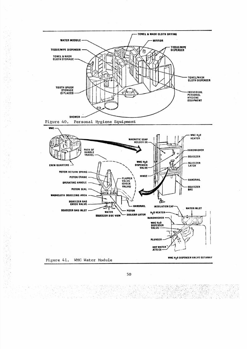
8/8/2019 MSFC Skylab Crew Systems Mission Evaluation
http://slidepdf.com/reader/full/msfc-skylab-crew-systems-mission-evaluation 74/397
CLOTH DRYING
WATER
F TIS_UEN_PETISSUE/WIPE DISPENSER
TOWEL & WASHCLOTH STORAGE
CLOTH DISPERSER
TO OT H B RUS HSTOWAGE
PERSONALHYGIENEEQUIPMENT
SHOWER
Figure 40. Personal Hygiene .Equipment
WMC
MAC H20AGNETIC SOAP I J HEATER
HOLDER (4)..--,
,--.HANDWASHER
-- SQUEEZER
_ _ _ WM C Hz Q _ SGUEEZER
CREW QUARTERS "_'_ DISPIENSER LATCH
F _--- HANORAIL
PISTON SEAL " _ SAG
i
INSULATION CAP "'-_\ WATER INLET
H20 HEATER.__- :\ J ',
HANDWASHER _ [ ["_-_"_-7_-
DISPENSER r-'- / "-'/" "--'_"- +'_VALVE----_;..,;;_, _-_, 1
PLUNGER.OTWATER'/")'
Figure 41. WMC Water Module WMC HzO DISPENSER VALVE CUTAWAY
5O
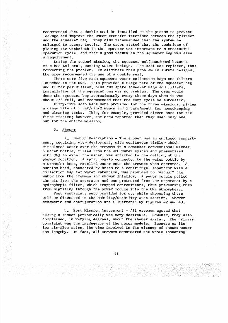
8/8/2019 MSFC Skylab Crew Systems Mission Evaluation
http://slidepdf.com/reader/full/msfc-skylab-crew-systems-mission-evaluation 75/397
recommended that a double seal be installed on the piston to prevent
leakage and improve the water transfer interface between the cylinder
and the squeezer bag. They also recommended that the system be
enlarged to accept towels. The crews stated that the technique of
placing the washcloth in the squeezer was important to a successful
operation cycle, and that a good vacuum in the squeezer bag was alsoa requirement.
During the second mission, the squeezer malfunctioned because
of a bad Bal seal, causing water leakage. The seal was replaced, thus
correcting the problem. To eliminate this problem in future designs,the crew recommended the use of a double seal.
There were five each squeezer water collection bags and filters
launched in the OWS. This provided a usage rate of one squeezer bag
and filter per mission, plus two spare squeezer bags and filters.
Installation of the squeezer bag was no problem. The crew would
dump the squeezer bag approximately every three days when it was
about 2/3 full, and recommended that the dump cycle be automatic.
Fifty-five soap bars were provided for the three missions, givinga usage rate of i bar an weeks and 5 bars/month for housekeeping
and cleaning tasks. This, for example, provided eleven bars for the
first mission; however, the crew reported that they used only onebar for the entire mission.
2. Shower
a. Design Description - The shower was an enclosed compart-
ment, requiring crew deployment, with continuous airflow whichcirculated water over the crewman in a somewhat conventional manner.
A water bottle, filled from the WMC water system and pressurized
with GN2 to expel the water, was attached to the ceiling at the
shower location. A spray nozzle connected to the water bottle bya transfer hose, expelled water onto the crewmen when operated. A
suction head, connected by hoses to a centrifugal separator with a
collection bag for water retention, was provided to "vacuum" the
water from the crewman and shower interior. A power module pulled
the air from the separator and was protected from the separator by a
hydrophopic filter, which trapped contaminents, thus preventing them
from migrating through the power module into the OWS atmosphere.
Foot restraints were provided for use while showering these
will be discussed in the Mobility/Stability Aids section. Shower
schematic and configuration are illustrated by Figures 42 and 43.
b. Post Mission Assessment - All crewmen agreed that
taking a shower periodically was very desirable. However, they also
complained, in varying degrees, about the shower system. The primary
complaint was the inadequacy of the power module. Because of its
low air-flow rates, the time involved in the cleanup of shower water
too lengthy. In factj all crewmen considered the whole showering
51
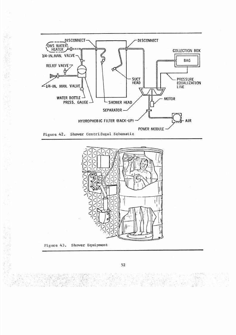
8/8/2019 MSFC Skylab Crew Systems Mission Evaluation
http://slidepdf.com/reader/full/msfc-skylab-crew-systems-mission-evaluation 76/397
_Of_-WS----'-,DISCONNECT-_WATER%
_I4-,N.MAN.ALVE-_
RELIEFVA_o .VALVWATER BOTrLE -J
PRESS. GAUGE-
Figure 42.
f DISCONNECT
' "Z_/ I-- SUCT _ PRESSURE
HEAD EQUALIZATION
" " MOTORSHOWER
SEPARATOR
HYDROPHOBICFILTER (BACK-UP) --/ _ AIR
_/POWER MODULE
Shower Centrifugal Schematic
Figure 43. Shower Equipment
52
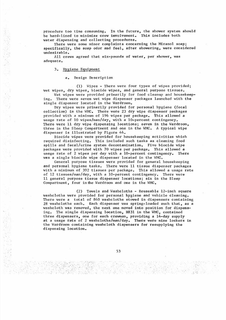
8/8/2019 MSFC Skylab Crew Systems Mission Evaluation
http://slidepdf.com/reader/full/msfc-skylab-crew-systems-mission-evaluation 77/397
procedure too time consuming, in the future, the shower system should
be hard-lined to minimize crew imvolvement. This includes both
water dispensing and collecting procedures.
There were some minor complaints concerning the Miranol soap;
specifically, the soap odor and feel, after showering, were considered
undesirable.All crews agreed that six-pounds of water, per shower, was
adequate.
3. Hygiene Equipment
a. Design Description
(i) Wipes - There were four types of wipes provided;
wet wipes, dry wipes, biocide wipes, and general purpose tissues.
Wet wipes were provided primarily for food cleanup and housekeep-
ing. There were seven wet wipe dispenser packages launched with the
single dispenser located in the Wardroom.
Dry wipes were primarily provided for personal hygiene (fecal
collection) in the WMC. There were 23 dry wipe dispenser packages
provided with a minimum of 196 wipes per package. This allowed a
usage rate of i0 wipes/man/day, with a 10-percent contingency.
There were ii dry wipe dispensing locations; seven in the Wardroom,
three in the Sleep Compartment and one in the WMC. A typical wipe
dispenser is illustrated by Figure 44.
Biocide wipes were provided for housekeeping activities which
required disinfecting. This included such tasks as cleaning food
spills and fecal/urine system decontamination. Five biocide wipe
packages were provided with 70 wipes per package. This allowed a
usage rate of 2 wipes per day with a 10-percent contingency. There
was a single biocide wipe dispenser located in the WMC.General purpose tissues were provided for general housekeeping
and personal hygiene tasks. There were ii tissue dispenser packages
with a minimum of 392 tissues per package. This allowed a usage rate
of 12 tissues/man/day, with a 10-percent contingency. There were
ii general purpose tissue dispenser locations; six in the Sleep
Compartment, four in_e Wardroom and one in the WMC.
(2) Towels and Washcloths - Reuseable 12-inch square
washcloths were provided for personal hygiene and vehicle cleaning.
There were a total of 840 washcloths stowed in dispensers containing
28 washcloths each. Each dispenser was spring-loaded such that, as a
washcloth was removed, the next one moved into position for dispens-
ing. The single dispensing location_ H831 in the WMC_ contained
three dispensers, one for each crewman, providing a 14-day supplyat a usage rate of 2 washcloths/man/day. There were nine lockers in
the Wardroom containing washcloth dispensers for resupplying the
dispensing location.
53
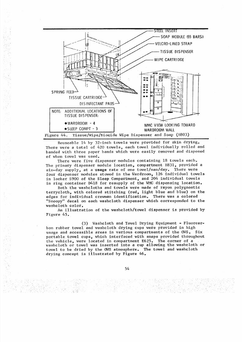
8/8/2019 MSFC Skylab Crew Systems Mission Evaluation
http://slidepdf.com/reader/full/msfc-skylab-crew-systems-mission-evaluation 78/397
, _STEEL INSERT
--_ _SOAP MODULE (55 BARSI
J_ VELCRO-LINED STRAP
DIS INFECTANT PADS --'-_
TISSUE DISPENSER: _ "_
• WARDROOM - 4 WMC VIEW LOOKING TOWARD
oSLEEP COMPT - 3 WARDROOM WALL
Figure 44. Tissue/Wipe/Biocide Wipe Dispenser and Soap (H803)
Reuseable 14 by 32-inch towels were provided for skin drying.
There were a total of 420 towels, each towel individually rolled and
banded with three paper bands which were easily removed and disposed
of when towel was used.
There were five dispenser modules containing 18 towels each.
The primary dispenser module location, compartment H831, provided a
six-day supply, at a usage rate of one towel/man/day. There were
four dispenser modules stowed in the Wardroom_ 126 individual towels
in locker $900 of the Sleep Compartment, and 204 individual towels
in ring container D418 for resupply of the WMC dispensing location.Both the washcloths and towels were made of rayon polygnostic
terrycloth, with colored stitching (red, light blue and blue) on the
edges for individual crewman identification. There was a colored
"Snoopy" decal on each washcloth dispenser which corresponded to thewashcloth color.
An illustration of the washcloth/towel dispenser is provided by
Figure 45.
(3) Washcloth and Towel Drying Equipment - Fluorcar-
bon rubber towel and washcloth drying cups were provided in high
usage and accessible areas in various compartments of the OWS. Six
portable towel cups, which interfaced with snaps provided throughout
the vehicle_ were located in compartment E625. The corner of awashcloth or towel was inserted into a cup allowing the washcloth or
towel to be dried by the OWS atmosphere. The towel and washcloth
drying concept is illustrated by Figure 46.
54
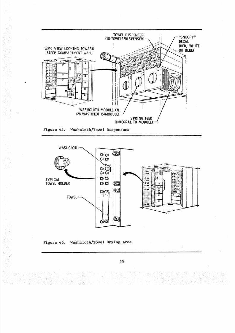
8/8/2019 MSFC Skylab Crew Systems Mission Evaluation
http://slidepdf.com/reader/full/msfc-skylab-crew-systems-mission-evaluation 79/397
WASHCLOTH MODULE (3)(28 WAS HCLOTHS/MODULE)
SPRING FEED(INTEGRAL TO MODULE)
Figure 45. Washcloth/Towel Dispensers
WASHCLOTH -_
TYP ICALTOWEL HOLDER
I
f
I
I
Figure 46. Washcloth/Towel D=ying Area
55
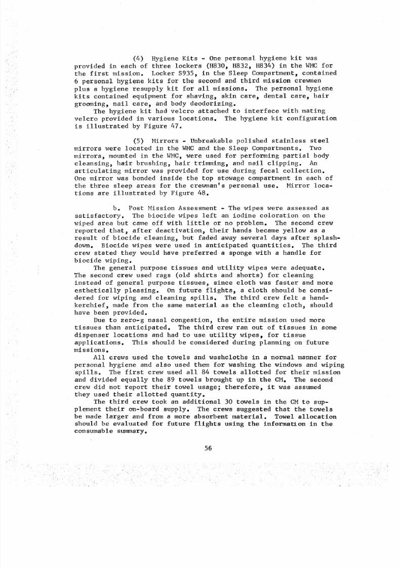
8/8/2019 MSFC Skylab Crew Systems Mission Evaluation
http://slidepdf.com/reader/full/msfc-skylab-crew-systems-mission-evaluation 80/397
(4) Hygiene Kits - One personal hygiene kit was
provided in each of three lockers (H830, H832, H834) in the WMC for
the first mission. Locker $935, in the Sleep Compartment, contained
6 personal hygiene kits for the second and third mission crewmen
plus a hygiene resupply kit for all missions. The personal hygiene
kits contained equipment for shaving, skin care, dental care, hair
grooming, nail care, and body deodorizing.
The hygiene kit had velcro attached to interface with mating
velcro provided in various locations. The hygiene kit configuration
is illustrated by Figure 47.
(5) Mirrors - Unbreakable polished stainless steel
mirrors were located in the WMC and the Sleep Compartments. Two
mirrors, mounted in the WMC, were used for performing partial body
cleansing, hair brushing, hair trimming, and nail clipping. An
articulating mirror was provided for use during fecal collection.
One mirror was bonded inside the top stowage compartment in each of
the three sleep areas for the crewman's personal use. Mirror loca-tions are illustrated by Figure 48.
b. Post Mission Assessment - The wipes were assessed as
satisfactory. The biocide wipes left an iodine coloration on the
wiped area but came off with little or no problem. The second crew
reported that, after deactivation, their hands became yellow as a
result of biocide cleaning, but faded away several days after splash-
down. Biocide wipes were used in anticipated quantities. The third
crew stated they would have preferred a sponge with a handle for
biocide wiping.
The general purpose tissues and utility wipes were adequate.
The second crew used rags (old shirts and shorts) for cleaning
instead of general purpose tissues, since cloth was faster and more
esthetically pleasing. On future flights, a cloth should be consi-
dered for wiping and cleaning spills. The third crew felt a hand-
kerchief, made from the same material as the cleaning cloth, should
have been provided.
Due to zero-g nasal congestion, the entire mission used more
tissues than anticipated. The third crew ran out of tissues in some
dispenser locations and had to use utility wipes_ for tissue
applications. This should be considered during planning on futuremissions.
All crews used the towels and washcloths in a normal manner for
personal hygiene and also used them for washing the windows and wiping
spills. The first crew used all 84 towels allotted for their missionand divided equally the 89 towels brought up in the CM. The second
crew did not report their towel usage; therefore, it was assumed
they used their allotted quantity.
The third crew took an additional 30 towels in the CM to sup-
plement their on-board supply. The crews suggested that the towels
be made larger and from a more absorbent material. Towel allocation
should be evaluated for future flights using the information in the
consumable summary.
56
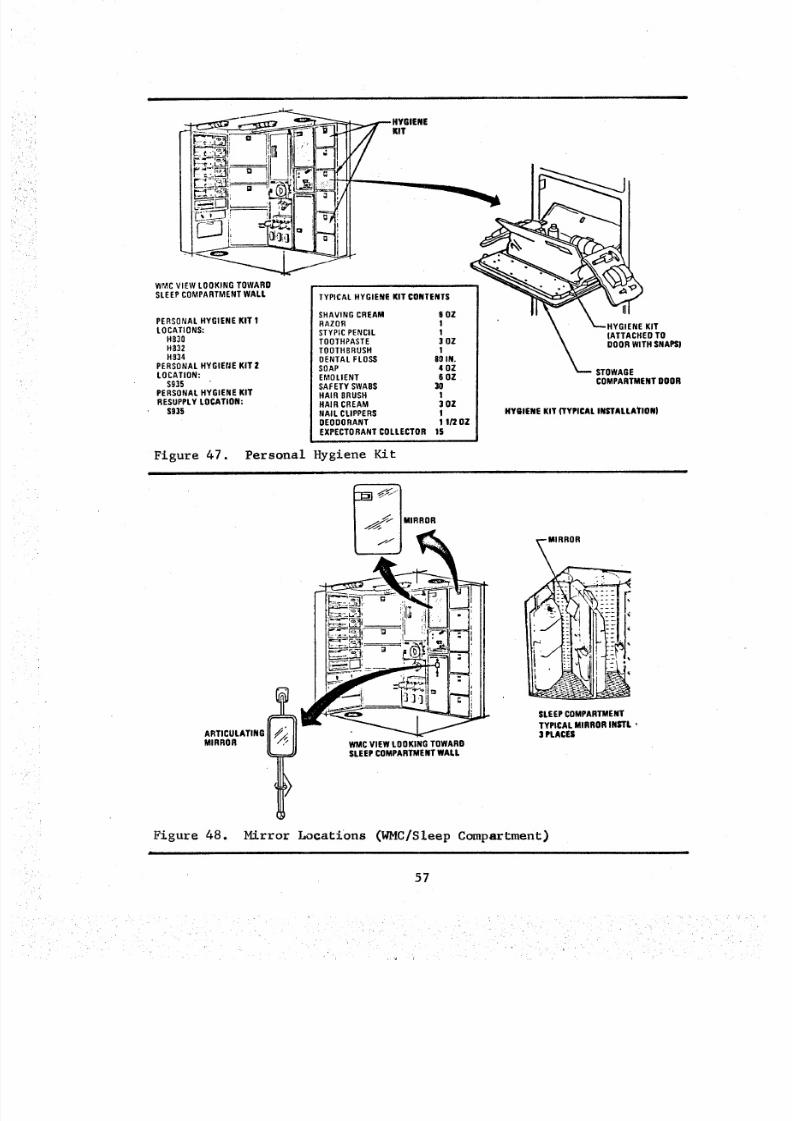
8/8/2019 MSFC Skylab Crew Systems Mission Evaluation
http://slidepdf.com/reader/full/msfc-skylab-crew-systems-mission-evaluation 81/397
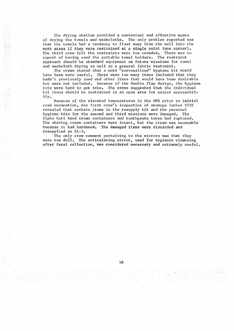
8/8/2019 MSFC Skylab Crew Systems Mission Evaluation
http://slidepdf.com/reader/full/msfc-skylab-crew-systems-mission-evaluation 82/397
The drying station provided a convenient and effective means
of drying the towels and washcloths. The only problem reported wasthat the towels had a tendency to float away from the wall into the
work areas if they were restrained at a single point (one corner).The third crew felt the restraints were too crowded. There was no
report of having used the portable towel holders. The restraint
approach should be standard equipment on future missions for towel
and washcloth drying as well as a general fabric restraint.
The crews stated that a more "personalized" hygiene kit would
have been more useful. There were too many items included that they
hadn't previously used and other items that would have been desirable
but were not included. Because of the double flap design, the hygienekits were hard to get into. The crews suggested that the individual
kit items should be restrained in an open area for easier accessibil-
ity.
Because of the elevated temperatures in the OWS prior to initial
crew occupation, the first crew's inspection of stowage locker $935
revealed that certain items in the resupply kit and the personalhygiene kits for the second and third missions were damaged. The
Alpha Keri hand cream containers and toothpaste tubes had ruptured.
The shaving cream containers were intact, but the cream was unuseable
because it had hardened. The damaged items were discarded and
resupplied on SL-3.
The only crew comment pertaining to the mirrors was that they
were too dull. The articulating mirror, used for hygienic cleansing
after fecal collection, was considered necessary and extremely useful.
58
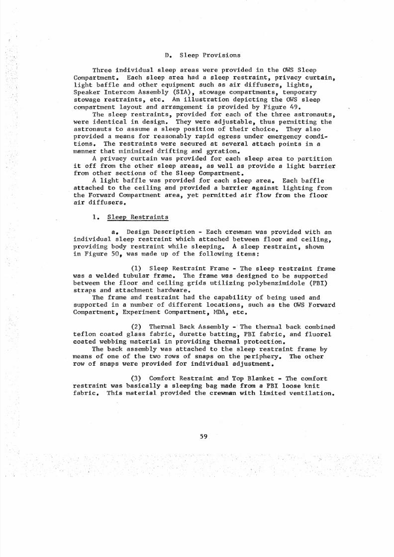
8/8/2019 MSFC Skylab Crew Systems Mission Evaluation
http://slidepdf.com/reader/full/msfc-skylab-crew-systems-mission-evaluation 83/397
_
i
D. Sleep Provisions
Three individual sleep areas were provided in the OWSSleepCompartment. Each sleep area had a sleep restraint, privacy curtain,light baffle and other equipment such as air diffusers, lights_Speaker Intercom Assembly (SIA), stowage compartments_ temporarystowage restraints, etc. An illustration depicting the OWSsleepcompartment layout and arrangement is provided by Figure 49.
The sleep restraints, provided for each of the three astronauts,were identical in design. They were adjustable_ thus permitting theastronauts to assumea sleep position of their choice. They alsoprovided a means for reasonably rapid egress under emergencycondi-tions. The restraints were secured at several attach points in a
manner that minimized drifting and gyration.
A privacy curtain was provided for each sleep area to partition
it off from the other sleep areas, as well as provide a light barrierfrom other sections of the Sleep Compartment.
A light baffle was provided for each sleep area. Each baffle
attached to the ceiling and provided a barrier against lighting from
the Forward Compartment area, yet permitted air flow from the floor
air diffusers.
i. Sleep Restraints
a. Design Description - Each crewman was provided with an
individual sleep restraint which attached between floor and ceiling,
providing body restraint while sleeping. A sleep restraint, shown
in Figure 50_ was made up of the following items:
(i) Sleep Restraint Frame - The sleep restraint frame
was a welded tubular frame. The frame was designed to be supportedbetween the floor and ceiling grids utilizing polybenzimidole (PBI)straps and attachment hardware.
The frame and restraint had the capability of being used and
supported in a number of different locations, such as the OWS Forward
Compartment_ Experiment Compartment_ MDA, etc.
(2) Thermal Back Assembly - The thermal back combined
teflon coated glass fabric, durette batting, PBI fabric, and fluorel
coated webbing material in providing thermal protection.
The back assembly was attached to the sleep restraint frame by
means of one of the two rows of snaps on the periphery. The other
row of snaps were provided for individual adjustment.
(3) Comfort Restraint and Top Blanket - The comfort
restraint was basically a sleeping bag made from a PBI loose knit
fabric. This material provided the crewman with limited ventilation.
59
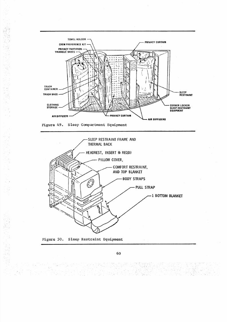
8/8/2019 MSFC Skylab Crew Systems Mission Evaluation
http://slidepdf.com/reader/full/msfc-skylab-crew-systems-mission-evaluation 84/397
TOWEL HOLDER ---_
CREW PREFERENCE KIT --_\
PRIVACY PARTITION -"'% \
TRIANGLESHOES_ _,
CONTAINER i ll_/,. ; .J+! \ I
AmO,FFUSER
Figure 49.
i i
% ,t ,_ l, , "
,_ PRIVACY CURTAIN
I,-- _ - _-_S'_!_"_, _L,_ I- I- I,. I- _,- I ",t _i ,_ _ _ / _li--.___,_' l
_;i _ _1_ _t_1"_f'Jl_..-_-i _-I _ ct'i i I il:'l' II
,9,_,-,-!-:_ _" I ( t I ll_l P"i,.L£_'::_ I ', t _IiI,41_-__] r_ i ! ! IIiTII ,
llIlT.-_-'ql l'l_._____.;il' I I _--SLEEe
_ _\ SLEEP RESTRAINT<, _ _ _ EQUIPMENT
L PRIVACY CURTAIN _ AIR OIFFU$ER$
Sleep Compartment Equipment
RESTRAINTFRAMEANDTHERMALBACK
y HEADREST, INSERT (6 REQD)
_._ PILLOW COVER,_ COMFORTRESTRAINT,
_ AND TOP BLANKET
_. _ ,,,,. i PULLSTRAP
Figur_ 50. Sleep Restraint Equipment
6O
8/8/2019 MSFC Skylab Crew Systems Mission Evaluation
http://slidepdf.com/reader/full/msfc-skylab-crew-systems-mission-evaluation 85/397
A stretchable knit fabric was used to make the upper or top
blanket. The crewman's head was placed through the expandable open-
ing allowing the blanket to be spread over the shoulders and chest
area,The restraint and top blanket were attached to the thermal back
by two zippers, one on each side.
(4) Bottom Blanket - The bottom blanket was made of
heavy PBI fabric containing two spandex "vee" panels. This blanket
attached to the bottom half of the thermal back by two zippers.
The blanket had a zippered stowage pouch near the bottom side of the
frame for restraining the blanket during launch and when not in use.
(5) Headrest Inserts - The headrest inserts consisted
of a PBI covered heat resistant foam panel. The sleep restraint
contained six headrest inserts on launch. These inserts were held
in place by an attached headrest cover. The crewman selected the
quantity of inserts providing the best head support.
(6) Headrest Cover - The headrest cover stretched
over the quantity of headrest inserts used. This cover was made of
PBI fabric and was attached by a zipper to the thermal back.The headrest provided a means to restrain the head from drift-
ing during sleep. A head restraint was fabricated from loose knit
PBI allowing for ventilation and was placed over the forehead or
entire head, at the crewman's option. One side of the head restraintwas sewn to the headrest cover. The other side was attached to the
thermal back with velcro.
(7) Body Straps - Three body straps were provided for
each sleep restraint and were constructed from stretch knit PBi fabric,
spandex, PBI webbing and fluorel coated webbing. The design of these
straps allowed them to stretch as the crewman changed his sleep
position. Adjustment in length was possible by releasing the buckles.
The straps were used to restrain the crewman's body while insideor outside the comfort restraints.
Soiled straps were changed periodically by releasing the buckles
at one end and disengaging snaps at the other end.
The sleep restraint assembly was installed in each sleep area
prior to launch. The frame, thermal back assembly, and headrest
inserts were used for all three missions with the other items being
changed periodical ly.
There were 27 comfort restralnt/top blankets stowed in the
Sleep Compartment, providing for a change every 14-days for eachsleep restraint.
There were 12 bottom blankets stowed, providing for a change
every 28 days for each sleep restraint. Twenty-seven headrest covers
were stowed, providing for a change every 14-days for each sleep
61
8/8/2019 MSFC Skylab Crew Systems Mission Evaluation
http://slidepdf.com/reader/full/msfc-skylab-crew-systems-mission-evaluation 86/397
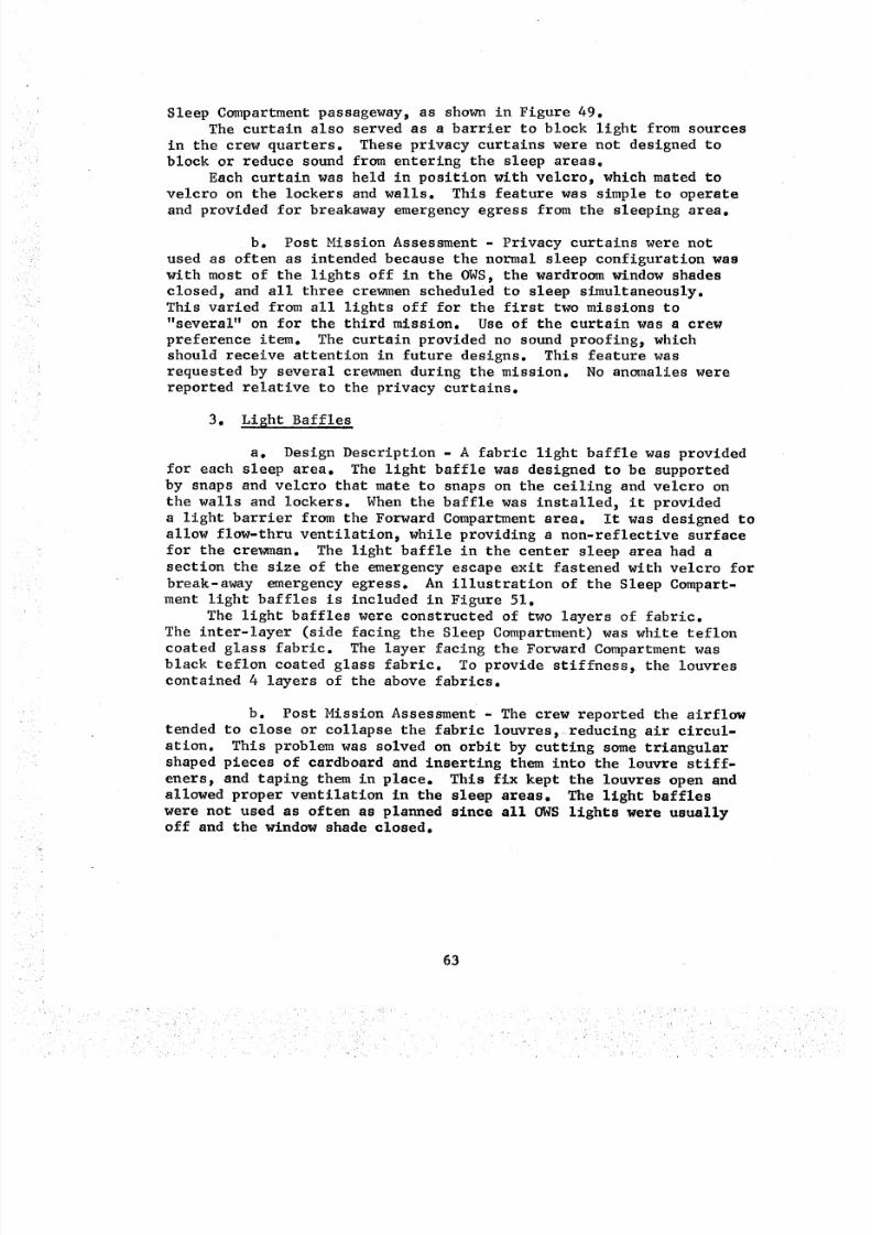
8/8/2019 MSFC Skylab Crew Systems Mission Evaluation
http://slidepdf.com/reader/full/msfc-skylab-crew-systems-mission-evaluation 87/397
Sleep Compartment passageway, as shown in Figure 49.
The curtain also served as a barrier to block light from sources
in the crew quarters. These privacy curtains were not designed to
block or reduce sound from entering the sleep areas=
Each curtain was held in position with velcro, which mated to
velcro on the lockers and walls. This feature was simple to operate
and provided for breakaway emergency egress from the sleeping area.
b. Post Mission Assessment - Privacy curtains were not
used as often as intended because the normal sleep configuration was
with most of the lights off in the OWS, the wardroom window shades
closed, and all three crewmen scheduled to sleep simultaneously.
This varied from all lights off for the first two missions to
"several" on for the third mission. Use of the curtain was a crew
preference item. The curtain provided no sound proofing_ which
should receive attention in future designs. This feature was
requested by several crewmen during the mission. No anomalies were
reported relative to the privacy curtains.
3. Lisht Baffles
a. Design Description - A fabric light baffle was provided
for each sleep area. The light baffle was designed to be supported
by snaps and velcro that mate to snaps on the ceiling and velcro on
the walls and lockers. When the baffle was installed, it provided
a light barrier from the Forward Compartment area. It was designed to
allow flow-thru ventilation, while providing a non-reflective surface
for the crewman. The light baffle in the center sleep area had a
section the size of the emergency escape exit fastened with velcro for
break-away emergency egress. An illustration of the Sleep Compart-
ment light baffles is included in Figure 51.
The light baffles were constructed of two layers of fabric.
The inter-layer (side facing the Sleep Compartment) was white teflon
coated glass fabric. The layer facing the Forward Compartment was
black teflon coated glass fabric. To provide stiffness, the louvrescontained 4 layers of the above fabrics.
b. Post Mission Assessment - The crew reported the airflow
tended to close or collapse the fabric louvres_ reducing air circul-
ation. This problem was solved on orbit by cutting some triangularshaped pieces of cardboard and inserting them into the louvre stiff-
eners, and taping them in place. This fix kept the louvres open and
allowed proper ventilation in the sleep areas. The light baffles
were not used as often as planned since all OWS lights were usuallyoff and the window shade closed.
63
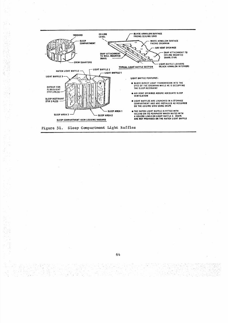
8/8/2019 MSFC Skylab Crew Systems Mission Evaluation
http://slidepdf.com/reader/full/msfc-skylab-crew-systems-mission-evaluation 88/397
tl i i i
INBOARD
LO'J;AR.,ENTI CREW QUARTERS
HATCH LIGHT BAFF_
LIGHT BAFFLE : I , _
FLOOOL,GHTt_
SL EE P A RE A )
CEILImG /-- BLACK ARMALOH SURFACE
LEVEL / _ FA CI NG CE IL IN G GR ID'_ __7-_,_ /-- WHITE ARMALON SURFACE
X FAC,NGCR__ Nr2 "-_ SNAP A_rACHMENT TO
SNAP.ACH,,ENT"'.."%."_-."O-._'_--.-----/ _"_'_-o_ -/ SNAPSYP,
_APS "_\_'_ --_L--'LIGHT.BAFFLEOUVE'STYPICAl, lIGHT BAFFLE SECTION (BLACK ARMALON INTERIOR)
LI GH T B AFF LE 2
T BAFFLE !
_LEEP AREA !
SLEEP AREA 2
LIGHT BAFFLE FEATURES-
• BLOCK DIRECT LIGHT TRANSMISSION INTO THEEYES OF THE CREWMAN WHILE HE IS OCCUPYINGTHE SLEEP RESTRAINT
• AIR VENT OPENINGS ASSURE ADEQUATE SLEEPVENTILATION
• L IG HT BA FFL ES A RE LA UNC HEO I N A S TO WA GECOMPARTMENT ANO ARE iNSTALLED AS REQUIRED
O N T HE C EI LI NG G RI D US IN G S NAP S
• TH E H ATC H LI GH T B AFF LE I S FI Ti 'E D WI THVELCRO ON ITS PERIPHERY WHICH MATES W1THAV ELCRO LINEd ON LI GHT BAFFLE 2. SNAPS
SLEEP COMPARTMENT VIEW LOOKING INBOARD A RE N OT PR OV IDE D O N TH E H ATC H LI GH T BA FFL E
Figure 51. Sleep Compartment Light Baffles
64
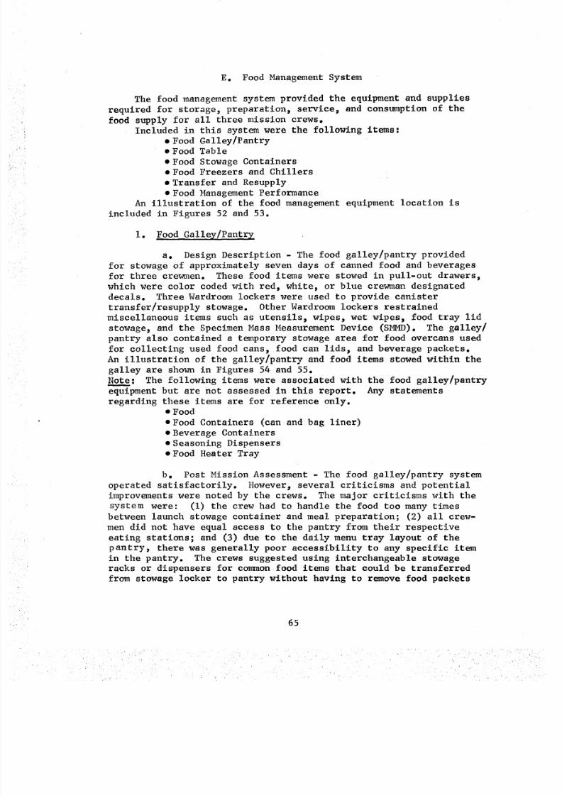
8/8/2019 MSFC Skylab Crew Systems Mission Evaluation
http://slidepdf.com/reader/full/msfc-skylab-crew-systems-mission-evaluation 89/397
E. Food Management System
The food management system provided the equipment and supplies
required for storage, preparation, service, and consumption of the
food supply for all three mission crews.
Included in this system were the following items:• Food Galley/Pantry• Food Table
• Food Stowage Containers• Food Freezers and Chillers
• Transfer and Resupply
• Food Management Performance
An illustration of the food management equipment location is
included in Figures 52 and 53.
I. Food Galley/Pantry
a. Design Description - The food galley/pantry provided
for stowage of approximately seven days of canned food and beveragesfor three crewmen. These food items were stowed in pull-out drawers,
which were color coded with red, white, or blue crewman designated
decals. Three Wardroom lockers were used to provide canister
transfer/resupply stowage. Other Wardroom lockers restrained
miscellaneous items such as utensils, wipes, wet wipes, food tray lid
stowage, and the Specimen Mass Measurement Device (SMMD). The galley/
pantry also contained a temporary stowage area for food overcans used
for collecting used food cans, food can lids, and beverage packets.An illustration of the galley/pantry and food items stowed within the
galley are shown in Figures 54 and 55.
Note: The following items were associated with the food galley/pantry
equipment but are not assessed in this report. Any statementsregarding these items are for reference only.
• Food
• Food Containers (can and bag liner)
• Beverage Containers
• Seasoning Dispensers
• Food Heater Tray
b. Post Mission Assessment - The food galley/pantry system
operated satisfactorily. However, several criticisms and potential
improvements were noted by the crews. The major criticisms with the
system were: (i) the crew had to handle the food too many times
between launch stowage container and meal preparation; (2) all crew-
men did not have equal access to the pantry from their respective
eating stations; and (3) due to the daily menu tray layout of the
pantry, there was generally poor accessibility to any specific itemin the pantry. The crews suggested using interchangeable stowage
racks or dispensers for co_aon food items that could be transferred
from stowage locker to pantry without having to remove food packets
65
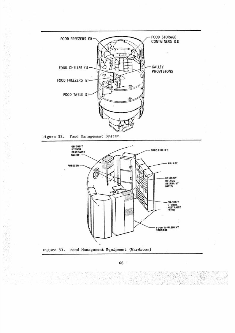
8/8/2019 MSFC Skylab Crew Systems Mission Evaluation
http://slidepdf.com/reader/full/msfc-skylab-crew-systems-mission-evaluation 90/397
FOOD STORAGEFOOD FREEZERS(3)-'_f_ _Jr_E"_ _/CONTAINERS (11)
_l{:_ C _ _ _;_'/_ GALLEYFOODCHILLER(1)-----_! _(; T_--I _-L-L
L/,_'_'___ PROVl S IONS..
FOODFREEZERS12)_-_l'_]fi --t ]11
FOOD TABLE (1)_-_ -'''r - AI>--.
Figure 52. Food Management System
Figure 53.
ON-ORBITUTENSILRESTRAINT
i!i:........
FREEZER ii _
,,e
i
_'_'_%_ " UTENSILI "_,LX\_ RESTRAINT
__ -..--. ,w77z)-:i!
-'-_'--_- ON-ORBITUTENSIL
: RESTRAINT
fijiiiiiiiiii!;ii_"'_ _'-_- FOOD SUPPLEMENT
STORAGE
Food Management Equipment (Wardroom)
66
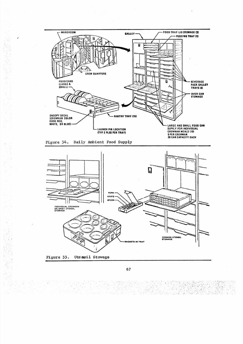
8/8/2019 MSFC Skylab Crew Systems Mission Evaluation
http://slidepdf.com/reader/full/msfc-skylab-crew-systems-mission-evaluation 91/397
GALLEY
: I}FOOD CANS I_qL_
CODE RED. JWHITE, OR BLUE) "ml
LAUNCH PIN LOCATION
TYP 2 PLC$ PER TRAY)
Figure 54. Daily Ambient Food Supply
/--- FOOD TRAY LID STOWAGE (3)PUDDING TRAY (1)
r I
_'- _ _0VERCAN
LARGE AND SMALL FOOD CAN
SUPPLY FOR INDIVIOUAL
CREWMAN MEALS (lS)
5 PER CREWMAN
20 CAN CAPACITY EACH
MAGNETS IN TRA
Figure 55. utensil Stowageam
67
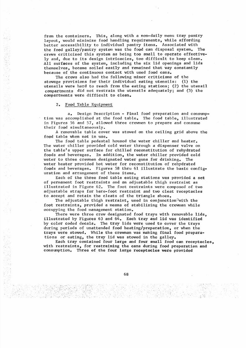
8/8/2019 MSFC Skylab Crew Systems Mission Evaluation
http://slidepdf.com/reader/full/msfc-skylab-crew-systems-mission-evaluation 92/397
from the containers. This, along with a non-daily menu tray pantry
layout, would minimize food handling requirements, while affording
better accessibility to individual pantry items. Associated with
the food galley/pantry system was the food can disposal system. The
crews criticized this system as being too small to operate effective-
ly and, due to its design intricacies, too difficult to keep clean.
All surfaces of the system, including the six lid openings and lids
themselves, became soiled easily and remained that way constantly
because of the continuous contact with used food cans.
The crews also had the following minor criticisms of the
stowage provisions for their individual eating utensils: (i) the
utensils were hard to reach from tile eating stations; (2) the utensil
compartments did not restrain the utensils adequately; and (3) the
compartments were difficult to clean.
2. Food Table Equipment
a. Design Description - Final food preparation and consump-tion was accomplished at the food table. The food table, illustrated
in Figures 56 and 57, allowed three crewmen to prepare and consume
their food simultaneously.
A removable table cover was stowed on the ceiling grid above the
food table when not in use.
The food table pedestal housed the water chiller and heater.
The water chiller provided cold water through a dispenser valve on
the table_s upper surface for chilled reconstitution of rehydrated
foods and beverages. In addition, the water chiller provided cold
water to three crewmen designated water guns for drinking. The
water heater provided hot water for reconstitution of rehydrated
foods and beverages. Figures 58 thru 61 illustrate the basic config-
uration and arrangement of these items.
Each of the three food table eating stations was provided a set
of permanent foot restraints and an adjustable thigh restraint as
illustrated in Figure 62. The foot restraints were composed of two
adjustable straps for bare-foot restraint and two cleat receptacles
to accept and retain the cleats of the triangle shoes.
The adjustable thigh restraint, used in conjunction_:'_ith the
foot restraints, provided a means of stabilizing the crewman while
occupying the food management station.
There were three crew designated food trays with removable lids,
illustrated by Figures 63 and 64. Each tray and lid was identified
by color coded decals. The tray lids wereused to cover the trays
during periods of unattended food heating/preparation, or when thetrays were stowed. While the crewman was making final food prepara-
tions or eating, the tray lid was stowed in the galley.
Each tray contained four large and four small food can receptacles,
with restraints_ for restraining the cans during food preparation andconsumption. Three of the four large receptacles were provided
68
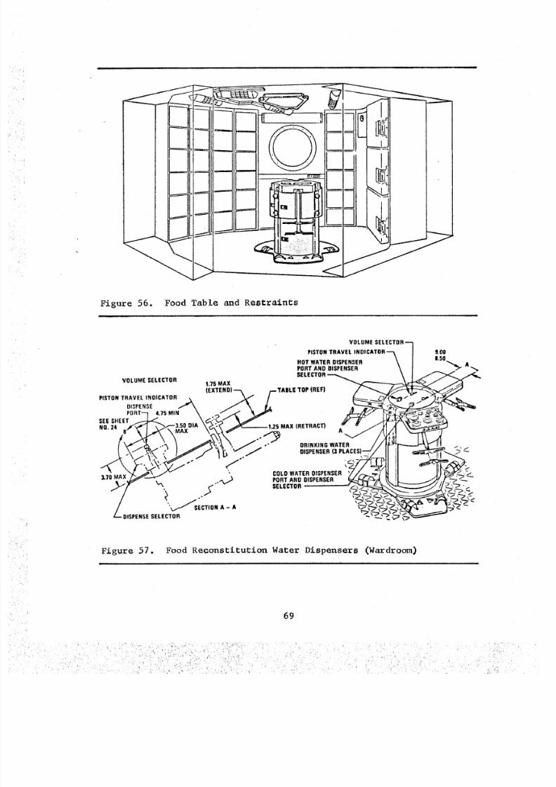
8/8/2019 MSFC Skylab Crew Systems Mission Evaluation
http://slidepdf.com/reader/full/msfc-skylab-crew-systems-mission-evaluation 93/397
tl
I II
I II41
i rl i
III
/
Figure 56. Food Table and Restraints
i ii
• VOLUME SELECTOR--_
PISTON TRAVEL INDI CATOR--'_ / S.00HOT WATER DISPENSER \ | 1.50 APORT AND DISPENSER _/ _ '",_SELECTOR_ \ J _,_"_ __
VOL°MEELECTOR_7'MAX _ _ _ "(I_XTEND)--_ /--TABLE TOP (REF) / _, _-'__//_
PirroNRAVELNDICATOR_ _ / _ _"i.-__PORT-- 4.7s M,. \ _ _ ____--'_L -SEES,EET .... .I
_LT0MAX_"--_ _ ._ PORT AND DISPENSER (_/:_'_/._, _ [_ _._;v'_'_, J,..--,y/ _ ,.-'" SELECTOR _____.J/J,_ _':
'_ SECTION A - A _./___._ _(_:_l_f_, . - "_. _ --
Z._o,sPE,,sEELECTO, _ _%_"
Figure 57. Food Reconstitution Water Dispensers (Wardroom)
n
69
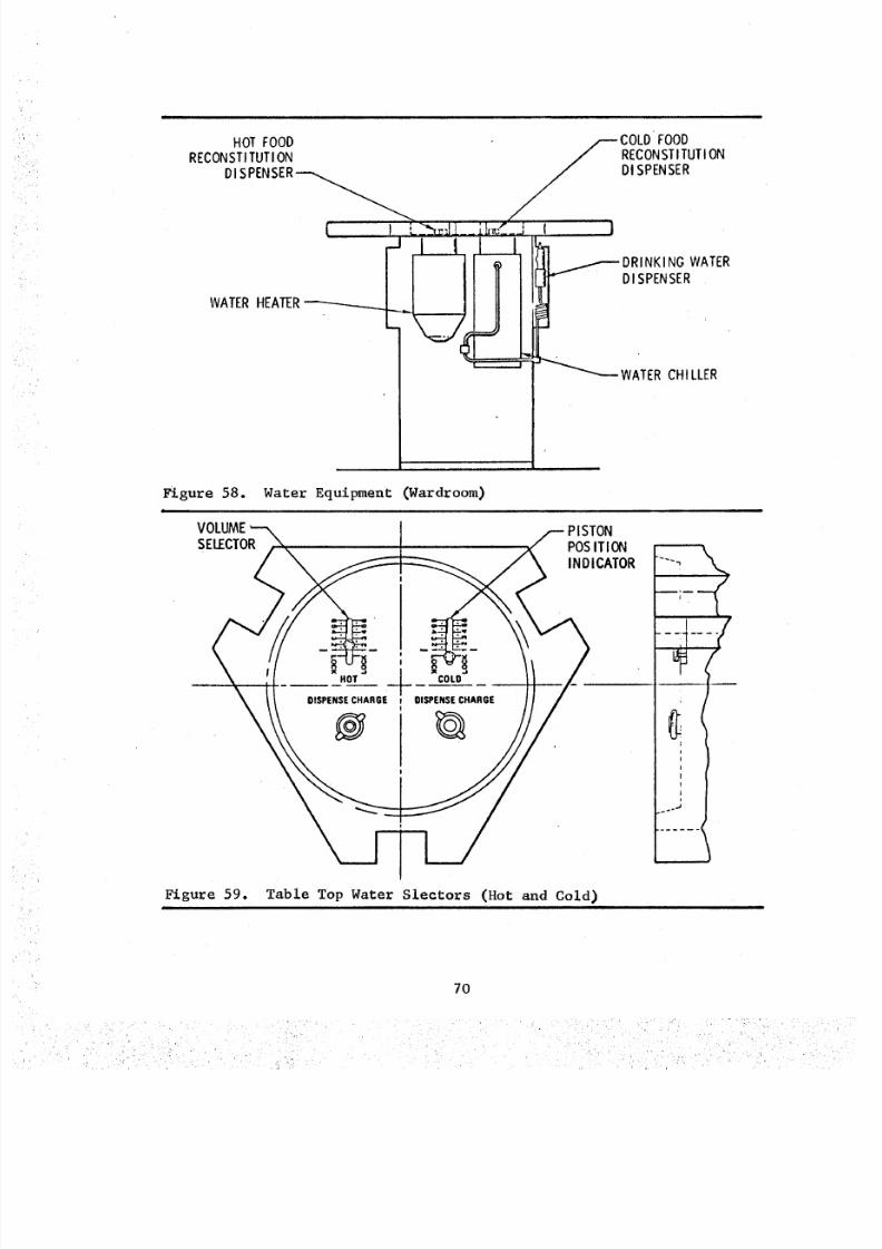
8/8/2019 MSFC Skylab Crew Systems Mission Evaluation
http://slidepdf.com/reader/full/msfc-skylab-crew-systems-mission-evaluation 94/397
HOT FOODRECONSTITUTION
DI SPENSER
WATERHEATER
COLDFOODRECONSTI TUTIONDISPENSER
_;_ w!_
' WATER CHI LLER
Figure 58. Water Equipment (Wardroom)|
VOLUMESELECTOR POS ITION
INDICATOR
DISPENSE CHARGE DISPENSE CHARGE
½
Figure 59. Table Top Water Slectors (Hot and Cold), i
70
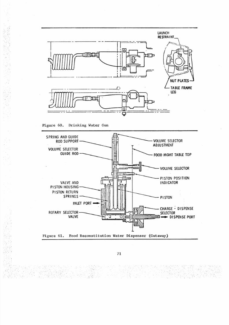
8/8/2019 MSFC Skylab Crew Systems Mission Evaluation
http://slidepdf.com/reader/full/msfc-skylab-crew-systems-mission-evaluation 95/397
I
. .. . i._ ;I '-"-'Y
.... ___._E._'
LAUNCHRESTRA NT
LEG
Figure 60. Drinking Water Gun
i
SPRING AND GUIDE
ROD SUPPORI_VOLUMESELECTOR
GUI DE ROD_'-'"_
VALVE AND LL_,_L IIPISTON HOUSINGs._ _.,._.._ Ei_._
SPRINGS _ IIIIII11iii II lilt H
ROTARY SELECTOR_
VA LVE _
_- _ VOLUME SELECTOR
,_ _._, ADJUSTMENTFOOD MGMT TABLE TOP
ElVOLUME SELECTOR
__'"-- PI STON POSITION
INDI CATOR
_ PI STON
'_ CHARGE - DISPENSESELECTOR
-,,,_ DISPENSE PORT
Figure 61. Food Reconstitution Water Dispenser (Cutaway)
71
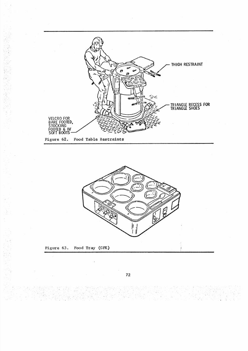
8/8/2019 MSFC Skylab Crew Systems Mission Evaluation
http://slidepdf.com/reader/full/msfc-skylab-crew-systems-mission-evaluation 96/397
VELCROFORBARE FOOTED,STOCKINGFOOTED& IVSOFTBOOTS
Figure 62.i
II _[ _ _,_/ /-TRIANGLE RECESS FORII _; _ ,_ TRIANGLE SHOES
"Food Table Restraints
Figure 63. Food Tray (GFE)
72
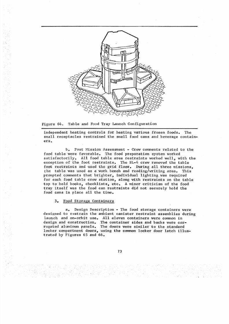
8/8/2019 MSFC Skylab Crew Systems Mission Evaluation
http://slidepdf.com/reader/full/msfc-skylab-crew-systems-mission-evaluation 97/397
Figure 64. Table and Food Tray Launch Configuration
independent heating controls for heating various frozen foods. The
small receptacles restrained the small food cans and beverage contain-
ers.
b. Post Mission Assessment - Crew comments related to the
food table were favorable. The food preparation system worked
satisfactorily. All food table area restraints worked well_ with the
exception of the foot restraints. The SL-4 crew removed the table
foot restraints and used the grid floor. During all three missions,
the table was used as a work bench and reading/writing area. This
prompted comments that brighter_ individual lighting was required
for each food table crew station_ along with restraints on the table
top to hold books_ checklists_ etc. A minor criticism of the food
tray itself was the food can restraints did not securely hold the
food cans in place all the time.
3. Food Storage Containers
a. Design Description - The food storage containers were
designed to restrain the ambient canister restraint assemblies duringlaunch and on-orbit use. All eleven containers were common in
design and construction. The container sides and backs were cor-
rugated aluminum panels. The doors were similar to the standard
locker compartment doors, using the common locker door latch illus-trated by Figures 65 and 66.
73
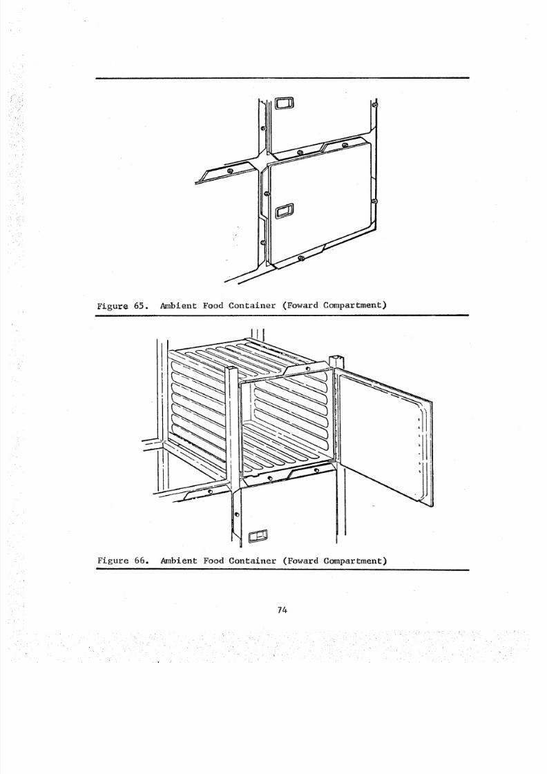
8/8/2019 MSFC Skylab Crew Systems Mission Evaluation
http://slidepdf.com/reader/full/msfc-skylab-crew-systems-mission-evaluation 98/397
Figure 65. Ambient Food Container (Foward Compartment)i
Figure 66. Ambient Food Container (Foward Compartment)
74
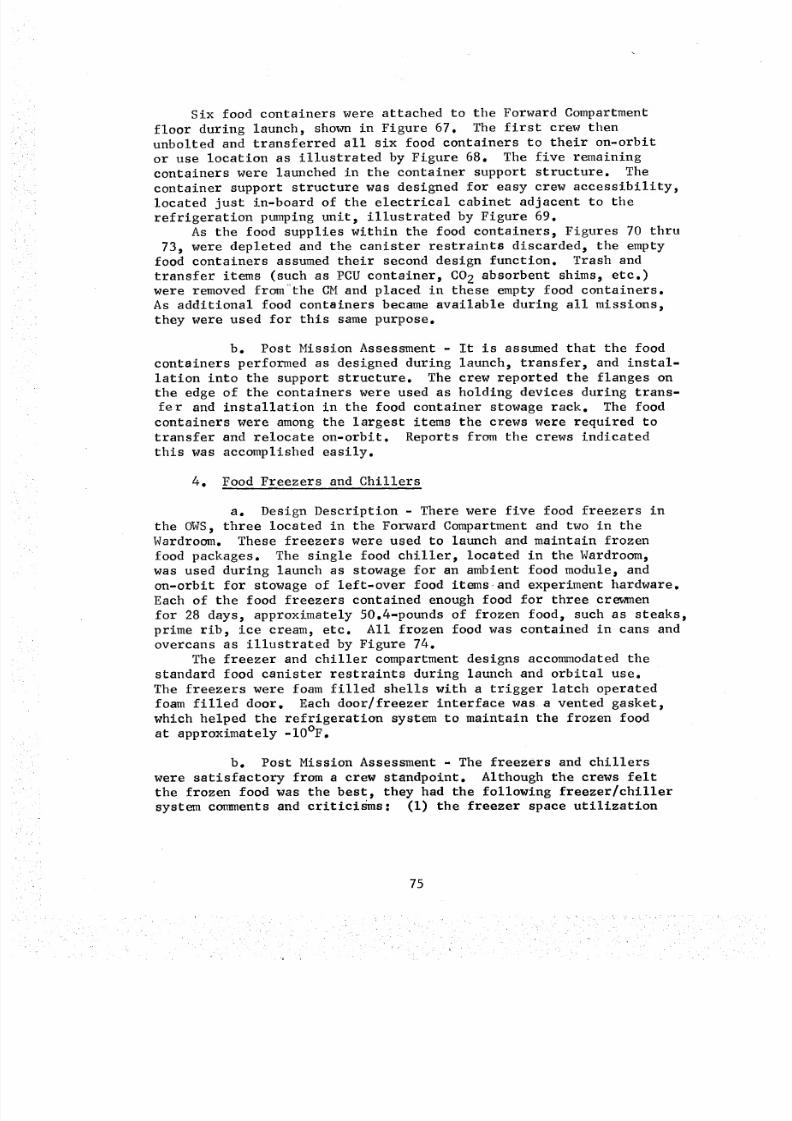
8/8/2019 MSFC Skylab Crew Systems Mission Evaluation
http://slidepdf.com/reader/full/msfc-skylab-crew-systems-mission-evaluation 99/397
Six food containers were attached to the Forward Compartmentfloor during launch, shown in Figure 67. The first crew thenunbolted and transferred all six food containers to their on-orbitor use location as illustrated by Figure 68. The five remainingcontainers were launched in the container support structure. Thecontainer support structure was designed for easy crew accessibility,located just in-board of the electrical cabinet adjacent to tilerefrigeration pumping unit_ illustrated by Figure 69.
As the food supplies within the food containers, Figures 70 thru73, were depleted and the canister restraints discarded_ the empty
food containers assumedtheir second design function. Trash andtransfer items (such as PCUcontainer, CO2 absorbent shims_ etc.)were removed from the CMand placed in these empty food containers.As additional food containers becameavailable during all missions_they were used for this samepurpose.
b. Post Mission Assessment- It is assumedthat the food
containers performed as designed during launch_ transfer_ and instal-lation into the support structure. The crew reported the flanges onthe edge of the containers were used as holding devices during trans-fer and installation in the food container stowage rack. The food
containers were amongthe largest items the crews were required totransfer and relocate on-orbit. Reports from the crews indicatedthis was accomplished easily.
4. Food Freezers and Chillers
a. Design Description - There were five food freezers in
the OWS_ three located in the Forward Compartment and two in theWardroom. These freezers were used to launch and maintain frozen
food packages. The single food chiller, located in the Wardroom,was used during launch as stowage for an ambient food module_ and
on-orbit for stowage of left-over food itemsand experiment hardware.
Each of the food freezers contained enough food for three crewmen
for 28 days, approximately 50.4-pounds of frozen food_ such as steaks,
prime rib_ ice cream, etc. All frozen food was contained in cans and
overcans as illustrated by Figure 74.
The freezer and chiller compartment designs accommodated the
standard food canister restraints during launch and orbital use.
The freezers were foam filled shells with a trigger latch operated
foam filled door. Each door/freezer interface was a vented gasket,
which helped the refrigeration system to maintain the frozen food
at approximately -10°F.
b. Post Mission Assessment - The freezers and chillers
were satisfactory from a crew standpoint. Although the crews felt
the frozen food was the best, they had the following freezer/chiller
system cormnents and criticisms: (I) the freezer space utilization
75
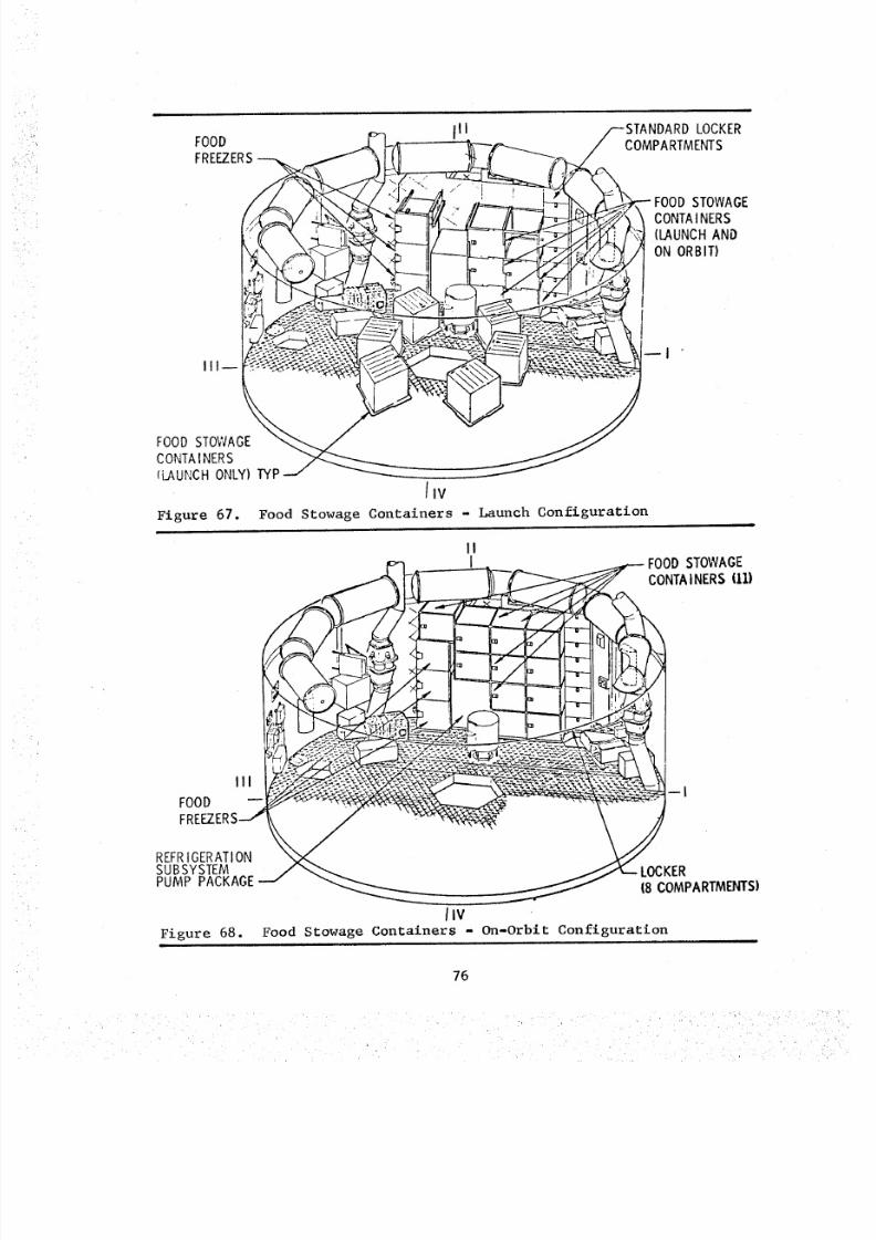
8/8/2019 MSFC Skylab Crew Systems Mission Evaluation
http://slidepdf.com/reader/full/msfc-skylab-crew-systems-mission-evaluation 100/397
FOODFREEZERS
III
/--STANDARD LOCKER
,, /COMPARTMENTS
FOOD STOWAGECONTAINERS(LAUNCH AND
ON ORBIT)
FOOD STOWAGE
CONTAINERS(LAUI_!CHNLY) TYP
IIv
Figure 67. Food Stowage Containers - Launch Configuration
III
FOOD
FRE
FOODSTOWAGECONTAINERS(I1)
REFRIGERATIONSUBSYSTEMPUMP PACKAGE
Figure 68.
LOCKER(B COMPARTMENTS)
/IVFood Stowage Containers - On-Orbit Configuration
76
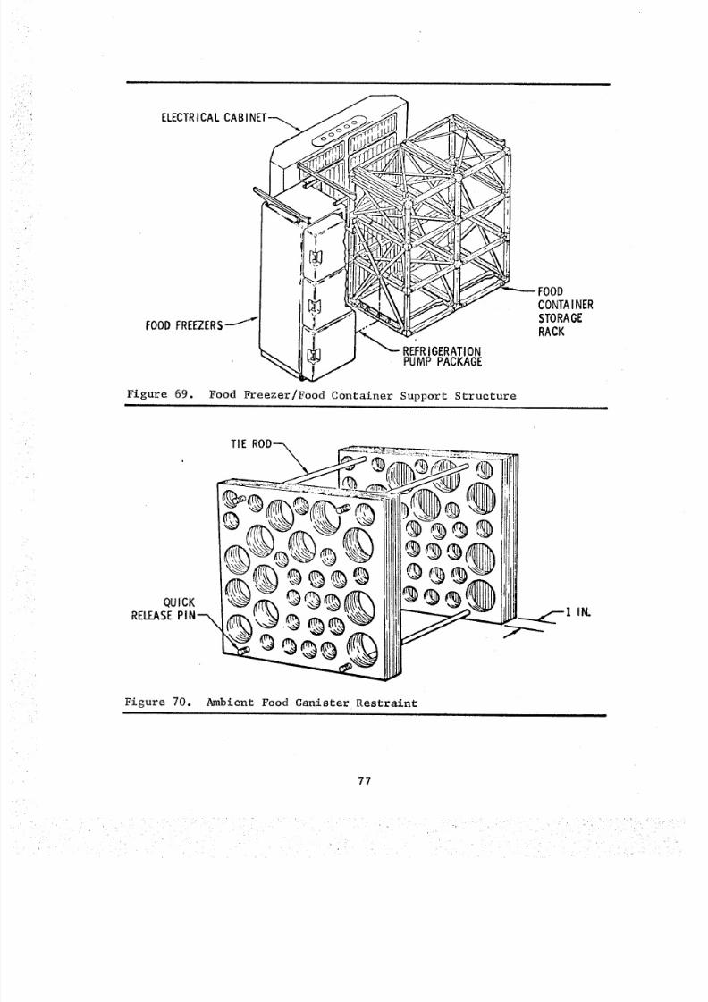
8/8/2019 MSFC Skylab Crew Systems Mission Evaluation
http://slidepdf.com/reader/full/msfc-skylab-crew-systems-mission-evaluation 101/397
i_ELECTRCA L CABINET
/I_1
FOODFREEZERS
FOO_INER
STORAGE
RACK
PUMP PACKAGE_'_ REFRIGERATION
Figure 69. Food Freezer/Food Container Support Structuretit i
Figure 70. Ambient Food Canister Restraint
77
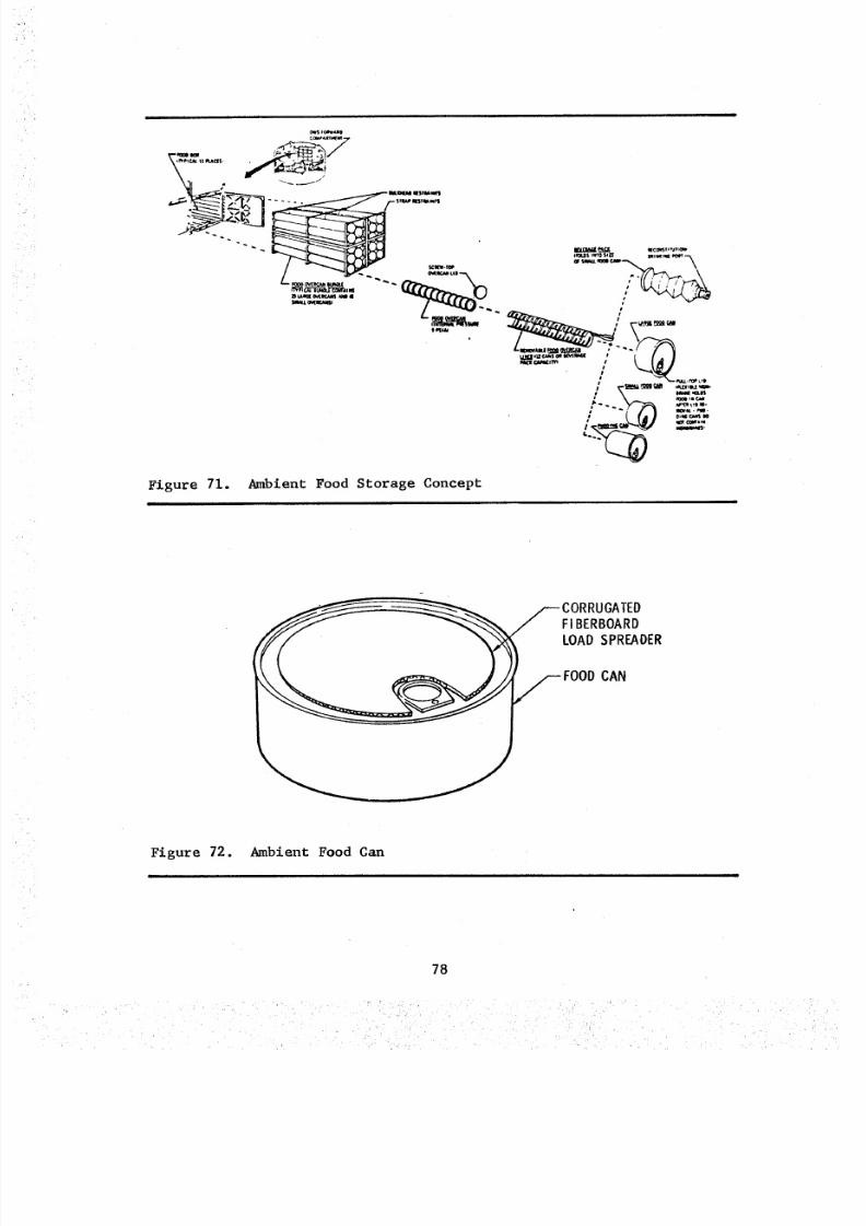
8/8/2019 MSFC Skylab Crew Systems Mission Evaluation
http://slidepdf.com/reader/full/msfc-skylab-crew-systems-mission-evaluation 102/397
Figure 71. Ambient Food Storage Concept
---CORRUGATEDFI BERBOARDLOAD SPREADER
/--- FOODCAN
Figure 72. Ambient Food Can
l
78
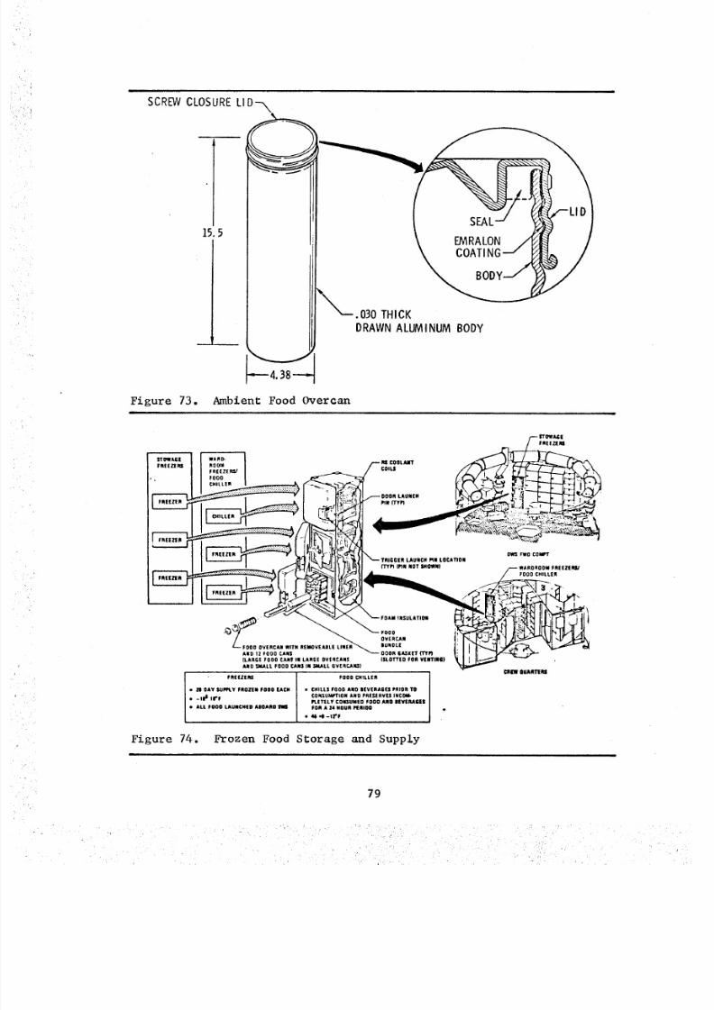
8/8/2019 MSFC Skylab Crew Systems Mission Evaluation
http://slidepdf.com/reader/full/msfc-skylab-crew-systems-mission-evaluation 103/397
SCREW CLOSURE LID-_
kll
15. SEAL-'5 _ EMRALON /_
X COATING--/_
,,'---. 030 THICK
DRAWNALUMINUM BODY
_--4. 38-----
Figure 73. Ambient Food Overcan
IRIIZIRI RO0_I \_
CH,LL,,I -- ..--oOO, .,cH _/:X/&_ _ _---$---;_
_ _ I_0 COWrTI ' ' I _f_l I _ L ii,I( l_i',_, TRIGGER LAD.CH .e tOCATIOR
ADD,2R G_xETm. li 'II _ _P'- -ILARGE FO0O CARS IN L AR GE O VE RC AI S |St_0TTEO F0R VEDTIII) I_ I I IL/._ 1 --
AHO _I4ALL FO OD CARl IN S MA LL Q VE Rr., .A KS )I_qGT QUARTERS
FREUERS F 00 B C HI LL ER
• _1 OAY SUPP_.Y FROZEN FOOD CACR • CHILLI FOOD AND lEVERAGES PRIOR TO
• -IP i IrF G OI C. _; UM I_ TI ON A ND P RE ,_ RV EI |RG_PI.ETELY CONSUMED PO0 0 AJgO B EVERAGES
• ALL FOE0 LAUNCHED ABOARD M FOR A 14 HOUR PIERIOD
• U '4 -II'F
Figure 74. Frozen Food Storage and Supply
79
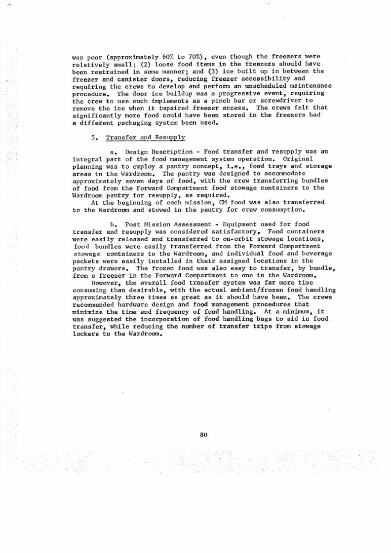
8/8/2019 MSFC Skylab Crew Systems Mission Evaluation
http://slidepdf.com/reader/full/msfc-skylab-crew-systems-mission-evaluation 104/397
was poor (approximately 60% to 70%), even though the freezers were
relatively small; (2) loose food items in the freezers should have
been restrained in some manner; and (3) ice built up in between the
freezer and canister doors, reducing freezer accessibility and
requiring the crews to develop and perform an unscheduled maintenance
procedure. The door ice buildup was a progressive event, requiring
the crew to use such implements as a pinch bar or screwdriver to
remove the ice when it impaired freezer access. The crews felt that
significantly more food could have been stored in the freezers had
a different packaging system been used.
5. Transfer and Resupp!y
a. Design Description - Food transfer and resupply was an
integral part of the food management system operation. Original
planning was to employ a! pantry concept, i.e., food trays and storage
areas in the Wardroom. The pantry was designed to accormnodate
approximately seven days of food, with the crew transferring bundlesof food from the Forward Compartment food stowage containers to the
Wardroom pantry for resupply, as required.
At the beginning of each mission, CM food was also transferred
to the Wardroom and stowed in the pantry for crew consumption.
b. Post Mission Assessment - Equipment used for food
transfer and resupply was considered satisfactory, Food containers
were easily released and transferred to on-orbit stowage locations,
food bundles were easily transferred from the Forward Compartment
stowage containers to the Wardroom, and individual food and beverage
packets were easily installed in their assigned locations in the
pantry drawers. The frozen food was also easy to transfer, by bundle,
from a freezer in the Forward Compartment to one in the Wardroom.
However, the overall food transfer system was far more timeconsuming than desirable, with the actual ambient/frozen food handling
approximately three times as great as it should have been. The crews
recommended hardware design and food management procedures that
minimize the time and frequency of food handling. At a minimum, it
was suggested the incorporation of food handling bags to aid in food
transfer, while reducing the number of transfer trips from stowagelockers to the Wardroom.
80
8/8/2019 MSFC Skylab Crew Systems Mission Evaluation
http://slidepdf.com/reader/full/msfc-skylab-crew-systems-mission-evaluation 105/397
L
r
F. Housekeeping
Equipment used for housekeeping included trash collection
equipment, a vacuum cleaner, and microbial control equipment.
I. Trash Collection - Trash was considered to be those items ofloose equipment no longer having a defined use. Trash was collected
by segregating it into two categories: biologically active trash,
such as urine bags and food cans; and nonbiologically active (inert)
trash, such as launch restraint hardware and non-flammable fiberboard
packing.
Biologically active trash was placed in bags and cycled throughthe Trash Airlock (TAL) into the waste tank.
Inert trash was placed in plenum (duffel) bags and stowed in the
plenum area aft of the crew quarters floor or in available lockers.
a. Design Description - Trash and disposal bags were
fabricated from vented armalon and were cylindrical in shape. The
bags were equipped with self enclosures which sealed the bag when full.
Trash bags were designed to be installed in a standard size
locker and attached to the inside of a special trash locker door. A
circular opening on the locker door allowed access to the bag diaphragm
for insertion of trash without opening the locker door. A hinged
access cover was located over the circular opening in the locker door.
Both dry and moist solids were disposed of in trash bags. When full,
trash bags were closed, taped, and disposed of through the TAL.
Trash bag location and configuration are depicted in Figure 75.
Disposal bags and urine disposal bags were designed to interface
with snap patterns provided throughout the vehicle. Disposal bags
were capable of containing urine separators_ charcoal canisters, or
other large disposable items considered as contamination sources.Urine disposal bags were designed to contain urine collection bags.
When full, they were closed, taped_ and disposed of through the TAL.
An illustration of the disposal bag is shown in Figure 75.
Plenum bags were designed to contain stowage trash which was not
considered a contamination source. The plenum bags were stowed in
the plenum area_ beneath the crew quarters floor, by attaching them
to cables provided in that location. Hooks for this attachment were
an integral part of the individual plenum bags. A plenum bag and its
orbital stowage is illustrated by Figures 75 and 76.
b. Post Mission Assessment - In general, the various trash
and disposal bags were used as planned on all missions. The trash
bag usage was less than anticipated, while the disposal bag usage
was greater than planned.
Only minor anomalies were encountered with trash collection
equipment during the entire mission. However, anomalies were reported
relative to problems which developed while cycling disposal bags
through the TAL. These problems are discussed in the Trash Disposal
section.
81

8/8/2019 MSFC Skylab Crew Systems Mission Evaluation
http://slidepdf.com/reader/full/msfc-skylab-crew-systems-mission-evaluation 106/397
i
! PX _W ( _( ; mN IA tN [ _ LOCATtON$
:N ', " ,,
• _'_ UP C_AmtW(tT
Figure 75. Trash Collection Bags
mmtam¢nmTAU_ R m _.Ot
e t5 V4 • Litre*6)
C_1_15 mtt[tm
PLENUM
STOWAGEBAG
Figure 76.
GENERAL PURPOSETRASH BAG LOCATION S
• FWO COMPARTMENT
eWARDROOMeWASTE MANAGEMENT COMPARTMENT• SL EEP COMPARTMENT
TRASH DUMP AREA
(WASTE TANK)
WAS TE TA_
SCREENS _J
Trash Disposal Subsystem
82
8/8/2019 MSFC Skylab Crew Systems Mission Evaluation
http://slidepdf.com/reader/full/msfc-skylab-crew-systems-mission-evaluation 107/397
The following paragraphs discuss problems and improvements
associated with the trash collection provisions:
(I) The location of the trash bags in the Wardroom
was such that the crewmen interfered with each other while trying
to obtain access to the trash lockers. The crew rearranged the trashlockers, thereby providing a more convenient trash disposal location
for each crewman. This was accomplished by removing the hinge pin
from a trash door and "swapping" it with a regular door at a differentlocation.
Until the rearrangement was accomplished, trash bags were not
being used as frequently as planned. As an example, during the first
mission, the crew "swapped" locker door W775 for locker door W750
to give the CDR a convenient place to put trash. They then swapped
locker door E621 with locker door W702 to give the SPT a convenient
location to put trash. This "swapping" kept the functions of each
locker the same. Lockers W750 and E621 were relocated trash lockers.
The crew also stowed a disposal bag on the snaps between the CDR's
seat and the doorway.
(2) The collection of wet wipes, used to clean food
and urine spills, wet washcloths, and towels_ etc._ should be
disposed of in an internal locker and not in a disposal bag thatstows on the wall.
(3) The location of bags in the Sleep Compartment was
satisfactory, but there was not much trash generated in this area.
(4) The trash bags were considered excellent and
worked very well. The plenum bags were effective for the dry trash,
such as empty washcloth containers, wipe containers, and towelcontainers when the crew ran short of disposal and urine disposalbags. The plenum bag was rated excellent because of this additional
stowage capability.
(5) The spring top on the urine disposal bags was
very convenient and worked well. It was pointed out that there should
be an easier way of sealing the urine disposal bags to prevent low
bleed leaks. The method used was acceptable, but it was considered
cumbersome. The flaps were wrapped around and snapped to prevent theurine disposal bags from venting in the waste tank.
(6) It was decided that there should be alternate
methods of trash disposal for future space stations. A trash compact-or, or something similar, was mentioned as a possible candidate.
A total of three hundred and sixty-six (366) trash bags were
launched. Of this quantity, 73 bags were allocated for the first
crew, but only 22 were used. The second crew was allocated 146 bags
83
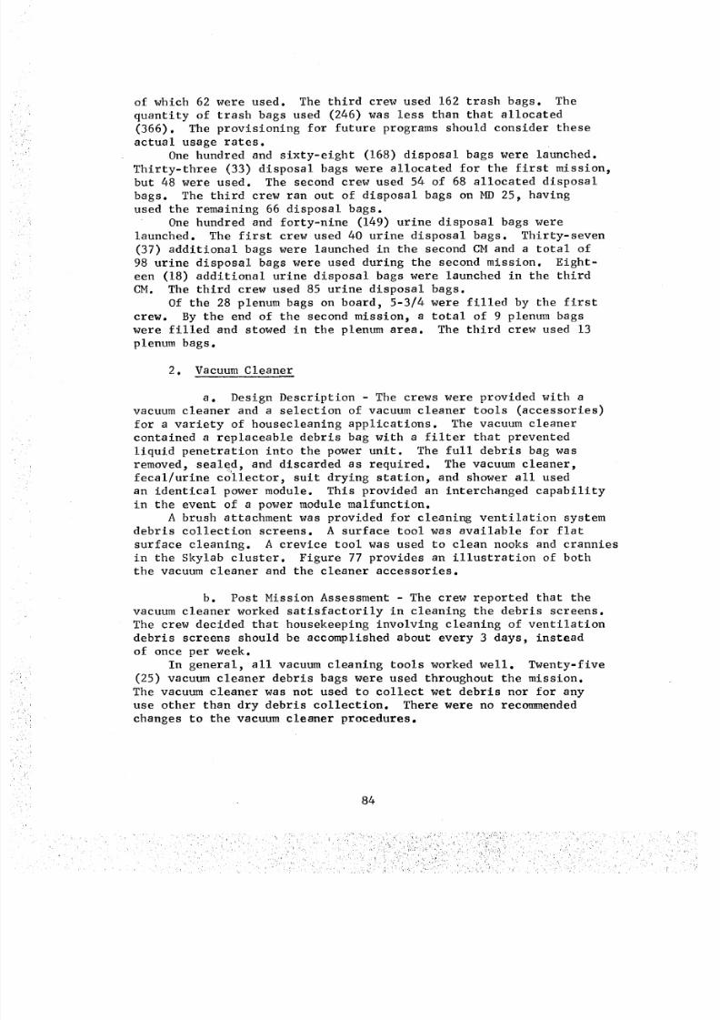
8/8/2019 MSFC Skylab Crew Systems Mission Evaluation
http://slidepdf.com/reader/full/msfc-skylab-crew-systems-mission-evaluation 108/397
of which 62 were used. The third crew used 162 trash bags. Thequantity of trash bags used (246) was less than that allocated(366). The provisioning for future programs should consider theseactual usage rates.
Onehundred and sixty-eight (168) disposal bags were launched.Thirty-three (33) disposal bags were allocated for the first mission,but 48 were used. The second crew used 54 of 68 allocated disposalbags. The third crew ran out of disposal bags on MD 25, havingused the remaining 66 disposal bags.
Onehundred and forty-nine (149) urine disposal bags werelaunched. The first crew used 40 urine disposal bags. Thirty-seven(37) additional bags were launched in the second CMand a total of98 urine disposal bags were used during the second mission. Eight-een (18) additional urine disposal bags were launched in the thirdCM. The third crew used 85 urine disposal bags.
Of the 28 plenum bags on board, 5-3/4 were filled by the firstcrew. By the end of the second mission, a total of 9 plenum bagswere filled and stowed in the plenum area. The third crew used 13plenum bags.
2. Vacuum Cleaner
a. Design Description - The crews were provided with avacuum cleaner and a selection of vacuum cleaner tools (accessories)
for a variety of housecleaning applications. The vacuum cleaner
contained a replaceable debris bag with s filter that prevented
liquid penetration into the power unit. The full debris bag was
removed, sealed, and discarded as required. The vacuum cleaner,fecal/urine collector, suit drying station, and shower all used
an identical power module. This provided an interchanged capability
in the event of a power module malfunction.A brush attachment was provided for cleaning ventilation system
debris collection screens. A surface tool was available for flat
surface cleaning. A crevice tool was used to clean nooks and crannies
in the Skylab cluster. Figure 77 provides an illustration of boththe vacuum cleaner and the cleaner accessories.
b. Post Mission Assessment - The crew reported that the
vacuum cleaner worked satisfactorily in cleaning the debris screens.
The crew decided that housekeeping involving cleaning of ventilation
debris screens should be accomplished about every 3 days, instead
of once per week.
In general, all vacuum cleaning tools worked well. Twenty-five
(25) vacuum cleaner debris bags were used throughout the mission.
The vacuum cleaner was not used to collect wet debris nor for any
use other than dry debris collection. There were no recommended
changes to the vacuum cleaner procedures.
84
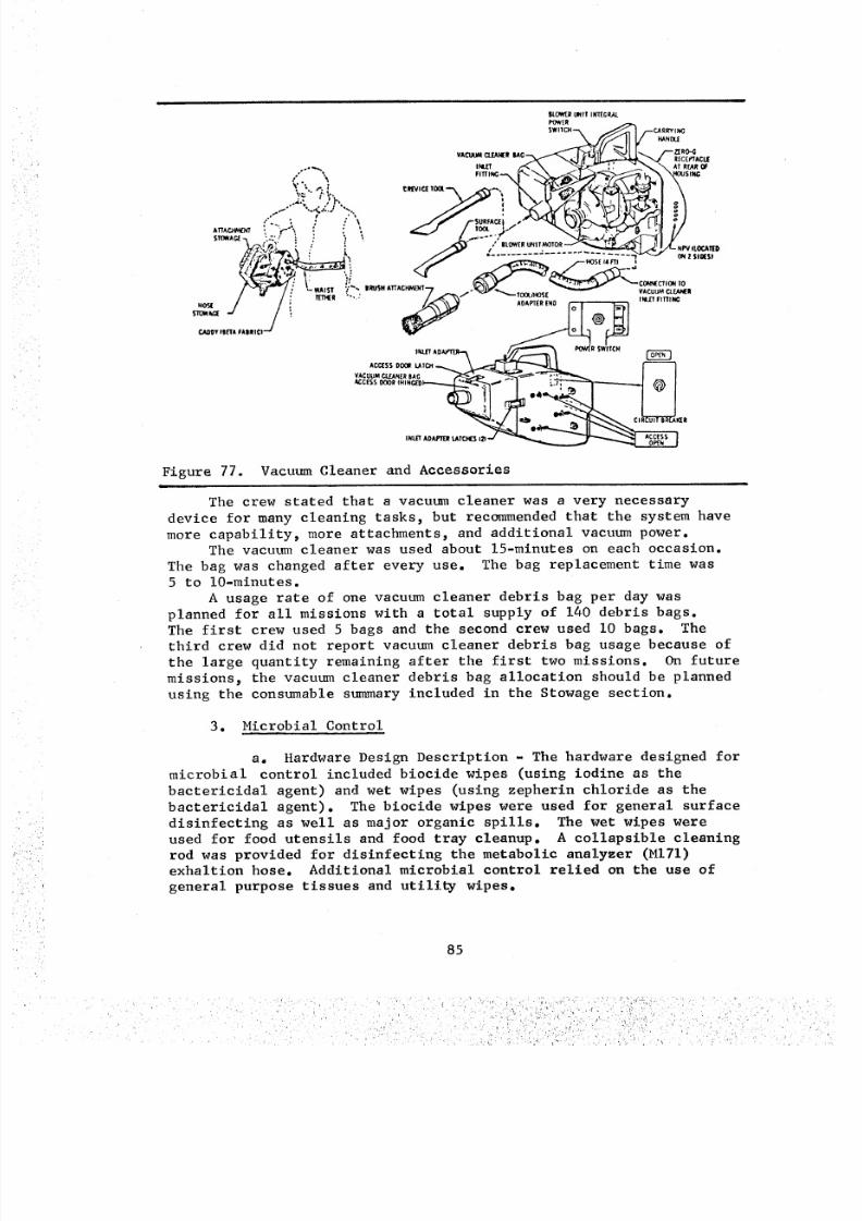
8/8/2019 MSFC Skylab Crew Systems Mission Evaluation
http://slidepdf.com/reader/full/msfc-skylab-crew-systems-mission-evaluation 109/397
Figure 77. Vacuum Cleaner and Accessories
The crew stated that a vacuum cleaner was a very necessary
device for many cleaning tasks_ but recommended that the system have
more capability, more attachments, and additional vacuum power.The vacuum cleaner was used about 15-minutes on each occasion.
The bag was changed after every use. The bag replacement time was
5 to lO-minutes.
A usage rate of one vacuum cleaner debris bag per day was
planned for all missions with a total supply of 140 debris bags.
The first crew used 5 bags and the second crew used I0 bags. The
third crew did not report vacuum cleaner debris bag usage because of
the large quantity remaining after the first two missions. On future
missions, the vacuum cleaner debris bag allocation should be planned
using the consumable summary included in the Stowage section.
3. Microbial Control
a. Hardware Design Description - The hardware designed for
microbial control included biocide wipes (using iodine as the
bactericidal agent) and wet wipes (using zepherin chloride as the
bactericidal agent). The biocide wipes were used for general surfacedisinfecting as well as major organic spills. The wet wipes were
used for food utensils and food tray cleanup. A collapsible cleaning
rod was provided for disinfecting the metabolic analyzer (MITI)exhaltion hose. Additional microbial control relied on the use of
general purpose tissues and utility wipes.
85
' 5,•
'rr•.
8/8/2019 MSFC Skylab Crew Systems Mission Evaluation
http://slidepdf.com/reader/full/msfc-skylab-crew-systems-mission-evaluation 110/397
b. Post Mission Assessment - The crews generally used the
microbial control equipment as planned. However_ they developed
some interesting variations. A rag bag was established in theCrew Quarters near the MI31 experiment for stowage of not too dirty
used clothing and towels. These articles were used for major clean-
up jobs, such as wiping urine spills. They also found that there
was considerable cleaning capability left in the wet wipes after the
first use. After cleaning up their eating utensils and tray, the
wet wipe was used to clean the wardroom area.
In general_ the wipes worked as planned. Crew comments relative
to potential microbiological contamination sources were quite
consistant among the three crews and can be summarized as follows:
(I) The area around the food table in the Wardroom,
both above the table and grid below, proved to be the most difficult
to keep clean. A suggestion for improving this situation was to
provide solid surfaces both above and below the immediate food table
area. A removable or hinged grid would also permit cleaning of free-floating food debris.
(2) The biocide wipes did a satisfactory job, but
were tedious to use. The crews would have preferred a single-stepbiocide that did not have to be washed off. A handle or holder for
the biocide wipes would have kept the iodine off the hands and would
have been preferred. The crew suggested an aerosol biocide and the
ability to clean up with rags. A request for an aromatic disinfectantp
rather than the aseptic odor of the current biocide, was voicedseveral times.
(3) Soft rags were superior to wipes for cleaning up
large areas. The allocation of wipes and tissues was insufficient.
Requests were made to have many more utility wipes and general purposetissues for future missions.
(4) Housekeeping schedules should not be rigid; that
is, most areas can be cleaned on an "as required" basis. The crew
thought there was too much housekeeping on a scheduled basis_ i.e._
the fecal seat was cleaned when it was dirty and not once a week, as
per schedule. Also, debris screens should be cleaned when they are
obviously dirty. Comments of this nature were voiced by all Skylab
crews. Housekeeping schedules may be relaxed to some degree in future
flights. However_ it must be kept in mind that microbial growth is
not always visible. The problem of growth of molds in the LiquidCooled Garments (LCGs) illustrate that once microbial growth gets
started_ it may be difficult to remove.
(5) The third crew experienced several minor urine
spills. The biocide wipes performed satisfactorily in handling these
86
S' %
8/8/2019 MSFC Skylab Crew Systems Mission Evaluation
http://slidepdf.com/reader/full/msfc-skylab-crew-systems-mission-evaluation 111/397
spills. The rupture of a urine bag in the trash airlock proved to
be a major source of odor. Repeated treatment with the biocidefailed to remove the odor from this area. It was believed that the
biocide did work on the accessible portion of the trash airlock.
However, urine may have passed under the lower lip of the TAL and
became entrapped, causing a foul aroma. The solution to this prob-
lem would appear to be a redesign of the TAL. Similar design prob-
lems were noted when cleaning the spills in the urine separator
compartments. The crews complained of poor accessibility whilecleaning spills. Poor lighting in the WMC made inspection and cleaning
of the urine drawers inadequate. Smooth surfaces within the drawer
would have made cleaning easier. There was no way to completelyclean the urine drawer.
(6) Some areas were omitted from the housekeeping
procedures. The food overcan disposal area was not on the house-
keeping procedure_ but became dirty with all the leftover food_and required frequent cleaning.
(7) A minor discoloration (iodine) to objects being
disinfected with the biocide wipes was reported. This was not consi-
dered significant and the crew did not report any serious objection.
The quantity of biocide wipes (350) provided for the Skylab mission
appeared to be adequate. The usage rate may be found in the Stowagesection consummable summary tables. No mention was made as to the
adequacy or inadequacy of the collapsible rod provided for cleaningof the MI71 metabolic analyzer exhalation hose. It was assumed that
the cleaning rod performed satisfactorily.
(8) The third crew commented that they found almost
everything "polished clean" and were really impressed with the
overall cleanliness of the vehicle. They complimented the second
crew on the effective and extensive cleaning job. The biocide
cleaning seemed to handle all reported contamination.
There were "definite odors" in the Wardroom, which eminated
from the food disposal wells. These were cleaned with biocide wipesevery 3 days.
87
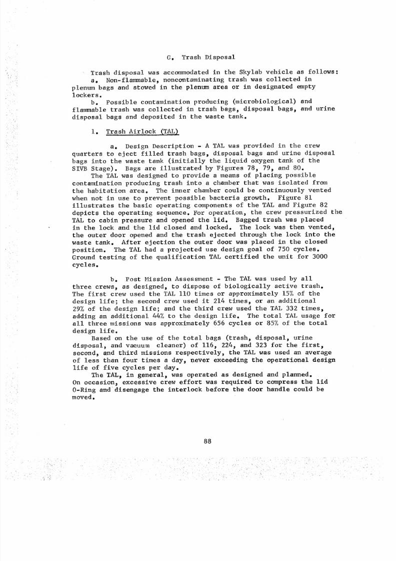
8/8/2019 MSFC Skylab Crew Systems Mission Evaluation
http://slidepdf.com/reader/full/msfc-skylab-crew-systems-mission-evaluation 112/397
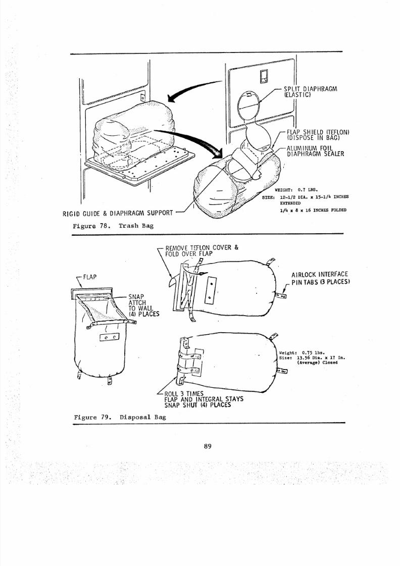
8/8/2019 MSFC Skylab Crew Systems Mission Evaluation
http://slidepdf.com/reader/full/msfc-skylab-crew-systems-mission-evaluation 113/397
RIGID GUIDE & DIAPHRAGM SUPPORT
Figure 78. Trash Bag
SIZEz
SPLIT DIAPHRAGM(ELAST C)
SHIELD (TEFLON)(DISPOSE IN BAG)
IMINUM FOILDIAPHRAGM SEALER
WEIGHT: 0.7 LBS.
12-i/2 DIA. x 15-1/h INCHES
EXTENDED
I/_ x 8 x 16 INCHES FOLDED
REMOVETEFLONCOVER &
_ROLL 3 TI MESFLAP AND INTEGRAL STAYSSNAP SHUT (4) PLACES
__Weight: 0.75 ibs.
._e: 13.56 Dia. x 17 In.
(Average) Closed
/Figure 79. Disposal Bag
89
• , .! ,
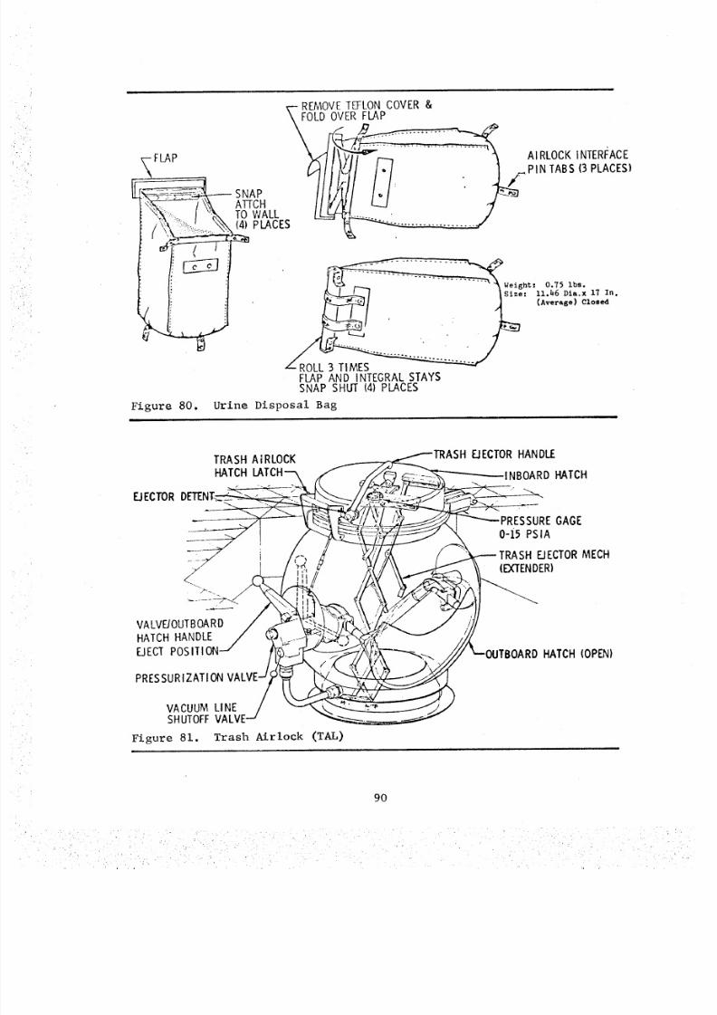
8/8/2019 MSFC Skylab Crew Systems Mission Evaluation
http://slidepdf.com/reader/full/msfc-skylab-crew-systems-mission-evaluation 114/397
REMOVETEFLONCOVER &TFOLD OVER FLAP
FLAP AI RLOCKINTERFACE_ ,_PIN TABS (3PLACES)
__ #k ATTCH II [f/VI L_.J _'1"_"-:_ I v_ TO WALL _ .... . /
__" We:ight-" 0.75 Ibs.
_1 Isi,_: n._,6 Pi,,._ 17 I,,._/ , . t (A'''''')'°''
FLAP AND INTEGRALSTAYSSNAP SHUT (4) PLACES
Figure 80. Urine Disposal Bag
EJECTOR
TRASH AIRLOCKHATCH
EIECTOR HANDIE
INBOARD HATCH
RESSURE GAGE0-i5 PSIA
_ECTOR MECH(EXTENDER)
VALVE/OUTBOARDHATCH HANDLE
EJECT POSITION
PRESSURIZATION
/VACUUM LINE /SHUTOFF VALVE---
Figure 81. Trash Airlock (TAL)
JTBOARD HATCH (OPEN)
9O
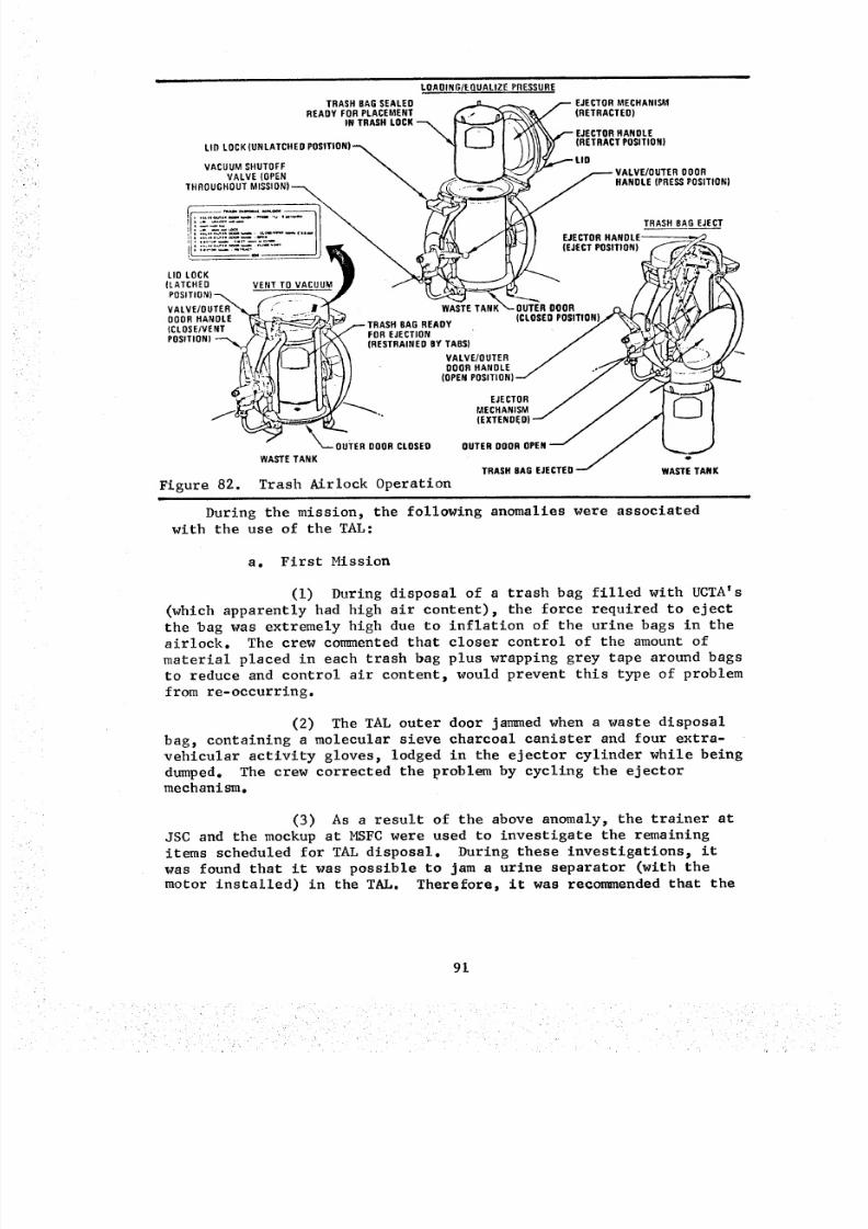
8/8/2019 MSFC Skylab Crew Systems Mission Evaluation
http://slidepdf.com/reader/full/msfc-skylab-crew-systems-mission-evaluation 115/397
iLOADING/EQUALIZE PRESSURE
TRASH BAGSEALED _ _ /-- EJECTORMECHANISMREADY FOR PLACEMENT _! _ _ _ (RETRACTED)
IN TRASH LOCK _ _ _ _"_\J _ I _ \ .--- EJECTORANDLE
L'°LOCK'ONLATCHEOPOS'T'ON)--\l L-JI t/ )7 ,RETRA.DS,T,D.)vAC,UMHUTOFF _ I I _ ._:...---t,O
"''VE _OPEN _ I ,[ _ .,--.---VALVE/OUTER DOOR
TH.OUO.'?._T,_,ONI---_
(LATCHED VENT TO VACUUM • / "°1 A'__ _ - /"_Vffi I1\\,'OS,T,ON)-_ _ __<.._.. / t/ff2A I1_\VALVE/OUTER_'_ I '_ ..RI]_-.._ WA,TETANK_'..-OUTERDOOR ,,_ I //1 I,,/.t'..,'L I_1ODOR,N?i'i "_-,;,__"_ ............. (CLO,EOOS,T,ON)_/I IP;Y" I I..... I NOR EJECT 0P0 SIT'0 N)"=_"_"');_ (RESTRAINED BY TABS) / _/_, //
/.(i JI H _,_"_ _ VALVE/OUTER / ....__,_..')- _/'_"B_LOI I_-"_ I t_I II " DOOR HANDLE / o'_" -I __
-,,._'%_..,_1 L.._ M I_,} /,/ EJECTOR / / l _ I
_,_-_-":-D_. .ECHAN,S" / J l II
ou,,..o,o.osE,A_E TANKWA_E TANK
Figure 82. Trash ,_irlock Operation
During the mission) the following anomalies were associatedwith the use of the TAL:
a. First Mission
(I) During disposal of a trash bag filled with UCTA's
(which apparently had high air content)) the force required to eject
the bag was extremely high due to inflation of the urine bags in the
airlock. The crew commented that closer control of the amount of
material placed in each trash bag plus wrapping grey tape around bags
to reduce and control air content, would prevent this type of problem
from re-occurring.
(2) The TAL outer door jammed when a waste disposal
bags containing a molecular sieve charcoal canister and four extra-
vehicular activity gloves) lodged in the ejector cylinder while being
dumped. The crew corrected the problem by cycling the ejector
mechanism.
(3) As a result of the above anomaly) the trainer at
JSC and the mockup at MSFC were used to investigate the remaining
items scheduled for TAL disposal. During these investigations) it
was found that it was possible to jam a urine separator (with the
motor installed) in the TAb. Therefore, it was recormnended that the
91
8/8/2019 MSFC Skylab Crew Systems Mission Evaluation
http://slidepdf.com/reader/full/msfc-skylab-crew-systems-mission-evaluation 116/397
crew should not attempt to dispose of the urine separators through the
TAL, but should stow them in the empty T027 Sample Array stowagecontainer. This container was then evacuated to inhibit possible
bacteria growth.
b. Second Mission
(I) Early in the second mission, a slow decrease in
habitation area pressure was noted. The magnitude of this leakage
was 6 ib/hr. The crew was awakened 6 hours later by the sound of
makeup gas being added to the cluster. They were instructed to check
the position of the TAL handle and found it midway between the posi-tions "PRESS" and "CLOSE/VENT." This position allowed leakage from
the habitation area through the TAL spool valve into the waste tank.
The handle had been bumped into this "midway" position several times
during the first mission; consequently, the second mission crew had
been cautioned about the potential problem. Following this incident,
the crew began restraining the TAL handle in the "PRESS" position,
between uses, with a general purpose restraint. No further instances
of leakage were traced to the TAL'.
(2) The interlock linkage between the lid lock and
the outer door handle was reported bent during TAL operation. In
the opinion of the crew, the damage did not appear to impair the
operation of the TAL or compromise the safety of the procedure. This
opinion was confirmed by ground tests. It was not clear, even after
the Second Mission Crew Technical Debriefing, whether the lid closing
and locking force had increased. The force required to compress the
0-ring sufficiently to disengage the lid-to-latch interlock, so that
the lid lock may be latched, had always been marginal for one man in
zero gravity. The recommendation was made for the third crew todeactivate the lid-to-latch interlock by taping. This reduced the
seal compression, and therefore the closing force required, prior
to latching.
Very little additional risk resulted from this interlock
deactivation. An assessment was made, using the mission support
TAL, to determine the cause of the interlock rod damage. It is
believed that the bent rod was a result of operating the lid latch
while the outer door handle was in the wrong position. This situation
would have caused the interlock rod to experience high compression
loads and possibly cause a slight bow (permanent set). Video tapesconfirmed that the bend was minor and no loss of interlock function
was involved. Additionally, the interlock rod had no effect on the
amount of force required to operate the lid latch.
A review of checkout data indicated that the on-board spare
seals did not exhibit associated closing forces significantly differ-ent from the onboard installed seal:
S/N (Installed): 21-25 ib
S/N 1 (Spare): 21-25 Ib
S/N 6 (Spare): 33-35 ib
S/N 1001D (Spare: 21-25 ib
92
8/8/2019 MSFC Skylab Crew Systems Mission Evaluation
http://slidepdf.com/reader/full/msfc-skylab-crew-systems-mission-evaluation 117/397
Although improvement did not seem likely with a seal changeout,
the crew was advised that if they wanted to "shop around" through
the spare seals and choose the one they considered best, this was
acceptable. The crew elected to leave the TAL "as-is".
c. Third Mission
(i) When the crew arrived there were 66 available
disposal bags onboard. The other bags available for use as trash
bags were the trash bags and the urine disposal bags. The urine
disposal bags were in short supply, so the crew used the trash bags
almost exclusively and saved the urine disposal bags for the disposal
of urine. The crew reported that the urine disposal bags worked well
and they initially got three to five full urine bags into the disposal
bag and through the TAL. About halfway through the mission, problems
developed with urine disposal bags jamming in the TAL. From that time
period through the end of the mission, the crew dumped urine through
the urine dump system and then rolled and taped the empty urine bags
and cycled them through then placed them in the TAL.
(2) The CDR performed as operator of the TAL for the
entire mission. He reported that he could operate the TAL by himself
at the beginning of the mission, but the system changed or became
warped, because later in the mission, he could no longer operate
it by himself. It became necessary for one man to stand on it, brace
his hands in the hatch on the floor above, and force the lid to the
TAL downward, while the CDR threw the latching handle up over the
edge of the lip of the cover and locked it down. On the average, TAL
dumps were necessary only about once every 3 days. The crew report
that, as trash accumulated, they would put it down in the well between
the TAL and the floor of the experiment compartment until there werefive or six bags. Trash dumps were usually done in the evening
before retiring.
(3) There was a major urine spill (leaking urine bag)
reported in the TAL about midway through the mission. This was
cleaned with biocide wipes. The crew reported that in spite of clean-
ing, a urine odor in the TAL persisted throughout the remainder ofmission.
(4) Another problem reported in the TAL operation was
the lack of mobility restraints for the operator. If the well was
full of trash bags, there was no room for the operator to anchor
himself by putting _ leg down into it.
Other than the anomalies discussed above, the operation of the
TAL was acceptable and accomplished its intended purpose during the
course of the three missions. Continuous care was exercised in
avoiding TAL operation with over-filled trash bags, i.e., more than
93
8/8/2019 MSFC Skylab Crew Systems Mission Evaluation
http://slidepdf.com/reader/full/msfc-skylab-crew-systems-mission-evaluation 118/397
two urine bags per disposal bag or large items with protrusions.
These precautions reduced the possibility of jamming. The later
mission crews continued to use some form of restraint to maintain
the valve/outer door control handle in the "CLOSE/VENT" or "PRESS"
position when the TAL was not in use. No items were reported to have
been cycled through the TAL without being placed in some type of bag.
The crews expressed on several occasions their dependence on the TAL
and their concern about the situation that would result from a
permanent malfunction. They also, occasionally, criticized the amountof time needed for trash disposal and termed the operation a "nuisance."
There was 2233-cubic feet of accessible volume in the waste tank
for the ejected trash items. This volume was consumed by biologicallyactive trash and can be expressed as a packing factor (volume avail-
able/volume used). Table 9 summarizes the full extended volume of
the various trash collection bags in determining the volumes and
packing factors for the waste tank. The trash bags were maintained
at approximately their extended volume by the sublimation of the ice
resulting from a moisture in their contents.
The first packing factor listed would be achieved at the end of
the last mission if all available trash bags were put through the
TAL. The second packing factor is for the waste tank at the end of
the first mission; and the third packing factor is at the end of the
second mission. The fourth packing factor denotes the completionof the third mission.
Additional biological passive trash was collected in the plenum
bags (4.5 cubic feet each). A total of 28 plenum bags (Figure 83)
were launched; 13 (a total of 58.5 cubic feet) were used during
the entire mission; however, only nine of these (40.5 cubic feet) areknown to have been stowed in the Plenum Area.
f S NAP H OOK S (T YP )
FULLY PACKED: h.5 CU. FT. -DRAWSIZE: 19 DIA. x hb INCHES EXTENDED STRING
Figure 83. Plenum Bag
94
8/8/2019 MSFC Skylab Crew Systems Mission Evaluation
http://slidepdf.com/reader/full/msfc-skylab-crew-systems-mission-evaluation 119/397
8/8/2019 MSFC Skylab Crew Systems Mission Evaluation
http://slidepdf.com/reader/full/msfc-skylab-crew-systems-mission-evaluation 120/397
H. Debris Control
I. Design Description - Airflow, used as a gravity substitute_
was the prime active method of debris control in the Skylab cluster.The airflow screen collectors were augmented by various types of
passive closeouts which were designed to keep debris out of inaccess-ible areas. Inaccessible areas were defined as any place where debris
was not visible or within reaching distance of a crewman. Special
tools were provided to assist in retrieving debris that eluded the
closeouts. The prime example of airflow debris collection was the
OWS. Air was circulated from a plenum chamber, under the crew quart-
ers area, through diffusers, to a mixing chamber located in the domearea and was returned to the plenum area by fans clustered in three
return air ducts. This configuration provided open area air velocity
ranging from 0.i0 to 0.23 meters/see (20 to 45 feet per minute) and
a screen velocity of 1.48 meters/see (283 ft./min.). The open gridconstruction of the OWS floor allowed adequate air and debris passage.
This velocity was sufficient to move all debris and loose parts tothe four 60-mesh screens in the dome area mixing chamber. Circulated
airflow_ similar to the OWS, was used in the other modules for debris
collection. Passive debris control was accomplished by use of various
types of closeouts. The flexible mesh, secured by velcro, in the
MDA was one type. See Figures 84 and 85 for other examples.The vacuum cleaner was designed to pick up the accumulated debris
from the screens and was scheduled periodically for that use. The
vacuum cleaner was also used to collect spilled liquids even though
the liquid systems (water, urine collection, personal hygiene and
food) were designed to minimize such occurrences.
2. Post Mission Assessment - Loose debris migrated to the areas
where the airflow was the greatest, i.e., MDA ventilation fans screen,OWS heat exchanger fans screen and OWS mixing chamber. The migration
of debris by the air circulation system made debris control with the
vacuum cleaner very convenient. The screen's effectiveness in debris
control was unexpected, but this principle should be capitalized in
future spacecraft designs. Passive debris closeouts are still required
to keep large objects from lodging behind equipment, lockers_ or
panels and are a necessary requirement for future design.
96
8/8/2019 MSFC Skylab Crew Systems Mission Evaluation
http://slidepdf.com/reader/full/msfc-skylab-crew-systems-mission-evaluation 121/397
8/8/2019 MSFC Skylab Crew Systems Mission Evaluation
http://slidepdf.com/reader/full/msfc-skylab-crew-systems-mission-evaluation 122/397
I. Hatches
i. OWS Access Hatch
a. Design Description - Initial entry into the OWS from
the AM was made through a 40" diameter OWS hatch located at the apex
of the dome, as illustrated in Figure 86. This hatch operated on twoin-line hinges, opened into the OWS area, and automatically latched
in place in a stowed position.The handle, located in the center or hub of the hatch, operated
at loads of approximately 25-1bs. This handle operated a cam/roller
action to the equalization position to separate the pivot fittings
from base fittings, opening nine .025-inch diameter holes for pressure
equalization. This handle locked automatically in either the open
or closed position. The hatch assembly consisted of two majorstructural parts which were the SIVB access-cover adapter and the
sealing hatch. This hatch contained redundant check valves and oper-
ating handles which could be used from either side.
b. Post Mission Assessment - The OWS hatch was used as the
aft airlock hatch for all EVAs. The second crew experienced some
difficulty securing the OWS hatch prior to EVA. The difficulty was
caused by performing hatch closing procedure steps out of sequence.
This caused no significant time delay in either the EVA prep or EVA.Performance of the OWS hatch hardware was nominal for all Skylab
missions.
2. MDA Hatches
a. Design Description - There were two MDA 30-inch diameter
pressure hatches, one located in each of the MDA docking port tunnels.
These hatches are illustrated in Figure 87. The hinges were designed
so that the hatch opened into the MDA to engage a detent latch for
stowage in the open position. The locking mechanism was a spider
arrangement of six latch assemblies operated by a center mounted
hatch handle. A delta pressure gage was provided in the hatch for
reading pressure from either side. Equalization across the hatch
(CSM tunnel to the MDA) was accomplished by using the hatch mounted
equalization valve that was capable of being manually operated fromeither side of the hatch. The valve had a screw-on cap on the CM side
over the valve orifice that had to be removed for valve operation.
A hatch locking device was provided on the CSM side of the
hatch. This locking latch restrained the hatch handle in the closedposition until released by a crewman. A contingency method forrelease of the hatch locking device from the MDA side consisted of a
T-handle bolt that was screwed through the door. As the bolt was
unscrewed, it allowed the launch lock to be released, which permitted
activation of the interior hatch handle_ releasing the door.
98
8/8/2019 MSFC Skylab Crew Systems Mission Evaluation
http://slidepdf.com/reader/full/msfc-skylab-crew-systems-mission-evaluation 123/397
*z
Figure 86. OWS Hatch
PI.ACiSI
CSM SIDE S
Figure 87.
CSM SIDE
REMOVECAPPRIORTOVALVEOPERATIONMDA Hatch
99
. . .*: .., : ?
8/8/2019 MSFC Skylab Crew Systems Mission Evaluation
http://slidepdf.com/reader/full/msfc-skylab-crew-systems-mission-evaluation 124/397
An additional contingency mode was provided on the axial hatch
by a tool box (MI04) that contained tools for forcing or dismantling
the hatch in case of opening mechanism failure.
b. Post Mission Assessment - For Skylab, the axial hatch
and its associated entry hardware performed as intended and all crew
operations were as specified in the checklist. There were no adversecrew comments on MDA hatch operations. However, as a note of interest,
the pressure equalization valve on the MDA hatches were designed withhandles on each side of the hatch. The pressure could not be equal-
ized until the screw-on cap on the external side of the equalization
valve was removed. This design presented no problems for the Skylab
mission, but a recent analyses of docking an unmanned module to
either MDA docking port brought to light that the use of the pressure
equalization valve, to equalize pressure between the two modules, wasinhibited because the screw-on cap would prevent pressure equaliza-
tion. In that case, pressure equalization would have to be accomp-
lished by removing a bolt that penetrated the pressure hatch. The
requirement to equalize pressure from the MDA side would have been
a contingency mode of operation and somewhat unlikely. However, the
screw on cap as a redundancy provision on hatch equalization valves
should be reconsidered when designing hatches for future spacecraft.
The redundant system should be in the valve itself rather than an
add-on device, that renders the valve inoperable when it is installed.
3. AM Hatches
a. Design Description
(I) Lock Compartment }latches - There were two AM
lock compartment hatches, each 49.5-inches in diameter with stiffenera
attached radially, as illustrated by Figure 88. An 8.5-inch
diameter dual pane window in each hatch enabled viewing of the lock
from both ends (aft and forward compartments). A pressure equalizationvalve was installed in each hatch which could be operated from either
side of both hatches and was used during pressurization and depres-
surization of the lock compartment. Only the forward AM hatch was
closed during EVA. The OWS hatch was closed in lieu of the aft AM
hatch to give additional space in the AM.
Each hatch was hinged to fold along the tunnel wall and was
restrained by a velcro strap. Each latching system used a cable that
ran along the periphey of each bulkhead and drove nine hatch latch
assemblies. An over-center feel device and a positive lock were
included in the handle mechanism. The aft hatch could be detached
from its hinge yoke by removing two quick release pins and could bere-installed at the flexible tunnel extension to isolate the AM from
the OWS for "contingency mode" operations.
(2) EVA Hatch - The EVA hatch, Figure 89, was
converted Gemini design which had a single motion latching mechanism
rather than the original rachet design. Two of the features which
i00
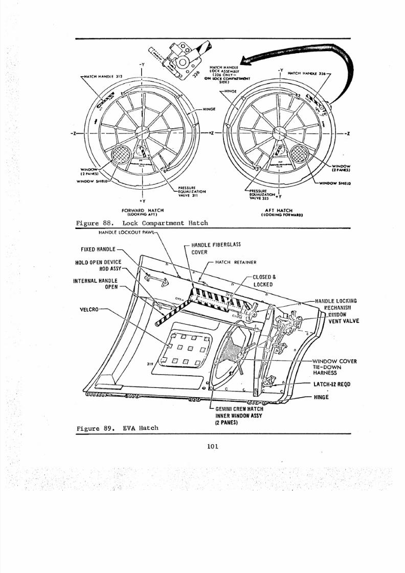
8/8/2019 MSFC Skylab Crew Systems Mission Evaluation
http://slidepdf.com/reader/full/msfc-skylab-crew-systems-mission-evaluation 125/397
HANDLE "11+
(2
WINDOW SHIEL©
Figure 88.t
PRESSURE
I EQUALIZATIONA|VE 311
+y
FORWARD HATCH(LOOKING AFT )
Lock Compartment Hatch
L'PRESSURE I
EQUALIZATION 'vVALVE 325 e'w
AFT HATCH
( LOOKING FORWARD)
HANDLE LOCKOUT PAWL--._
\FIXED HANDLE
\HOLD OPEN DEVICE \
ROD ASSY'-'_
INTERNAL HANDLEOPEN "-'-
\
HANDLE FIBERGLASS
COVER
HATCH RETAINER
:LOSED &
LOCKED
VELCRO_
(3 pAz4[.S)
SHIELD
LOCKIRG_!ECHANIS/A
)OWVENT VALVE
Figure 89. EVA Hatch
GEMINI CREWHATCH
INNER WINDOWASSY
(2 PANES)
I01
)OW COVERTIE-DOWNHARNESS
LATCH-IZ REQD
HINGE
8/8/2019 MSFC Skylab Crew Systems Mission Evaluation
http://slidepdf.com/reader/full/msfc-skylab-crew-systems-mission-evaluation 126/397
this hatch provided were: (a) the handle lockout, and (b) thehatch retainer. The handle lockout prevented the latching dogs from
being closed when the hatch is in an open position, thereby precluding
sill damage which might occur due to closing the hatch in that
configuration. The hatch retainer caught the hatch in a partially
open position as it was being opened, thus preventing differential
pressure loads from popping the hatch open if the lock compartment
was not completely vented.
A double pane window in the hatch enabled viewing of the aft
portion of the EVA bay. The space between the panes could be vented
with the window vent control.
b. Post Mission Assessment - The lock and aft compartment
entry was normal and no problems were experienced with forward and
aft hatches. Egress/ingress operation during the EVA's thru the EVA
hatch was reported satisfactory.
During the SL-2 Crew Debriefing, a suggestion was made to add a
second removable screen to the hatch equalization valve, to compensatefor icing during depressurization. The crew stated that both internal
and EVA hatch sizes were satisfactory and they had no problems in
handling the hatches during opening and closing.
102
8/8/2019 MSFC Skylab Crew Systems Mission Evaluation
http://slidepdf.com/reader/full/msfc-skylab-crew-systems-mission-evaluation 127/397
J. Crew Stations
The term crew station is generally associated with areas where
a crewman was scheduled to spend considerable time in the performance
of assigned tasks. This section will discuss work space, layout,
reach envelopes, habitability, and compatibility between crew stations.Crew provisions within each crew station, such as lighting, restraints,communications, etc., are discussed in detail in other sections of
this report.
I. MDA Crew Station
a. Design Description - Crew stations in the MDA were
designed to provide for: (i) passage between the Command Service
Module (CSM) and the AM; (2) stowage of hardware and experiment
support equipment; (3) CSM probe and drogue stowage; and (4) perform-
ance of experiments. The primary MDA crew stations were the Apollo
Telescope Mount Control and Display Console (ATM C&D), Earth Resources
Experiment Package (EREP) C&D panel, EREP Viewfinder Tracking System
(VTS), and the M512/479 Material Processing Facility. Figures 90 and91 illustrate these crew stations.
With the expansion of the MDA-installed experiments, it became
obvious that task and volume sharing would be required as part of
crew station definition. Crew convenience and optimum work station
classification of equipment were compromised by continual additions
of stowage items to the MDA, even after stowage closeout of the
OWS st Kennedy Space Center (KSC). This form of configuration develop-
ment resulted in a partially unorganized arrangement of the MDA hard-
ware and equipment, which was installed circumferentially around themodule.
(I) ATM C&D Crew Station - The ATM C&D crew station
consisted of the ATM C&D panel, foot restraint platform, chair, and
Speaker Intercom Assembly (SIA). The ATM C&D console was originallydesigned for seated operation and installation in the Lunar Module
for AAP. Although changes were made in the panel for Skylab, its
basic size and shape remained unchanged. Early in the program, the
crewmen elected to operate the ATM C&D panel from a standing position
on the premise that: (a) two crewmen may be required at the ATM C&D,
and (b) the STS control and display panel would require monitoring
while the crewmen were physically oriented at the ATM C&D panel. At
the time Skylab was being readied at KSC, the Skylab Restraint
Assembly (Chair) was installed, at the request of the crew, to provide
additional restraint while operating the ATM C&D panel.
(2) EREP C&D Crew Station - The EREP C&D crew station
consisted of the C&D panel, the S190 camera array, the S190 stowage
container, a SIA, and the M512/479/EREP foot restraint. The major
i03
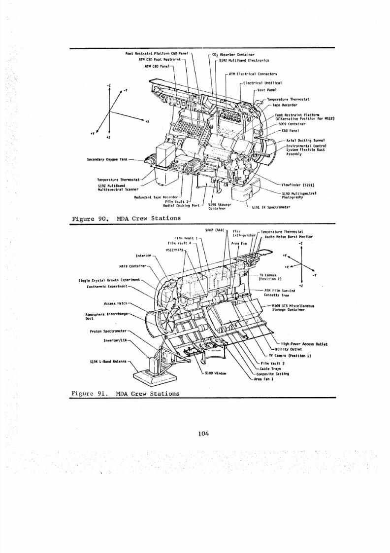
8/8/2019 MSFC Skylab Crew Systems Mission Evaluation
http://slidepdf.com/reader/full/msfc-skylab-crew-systems-mission-evaluation 128/397
Foot Restraint Platform C&D
ATM C&O Foot
ATH
+Y
-Z
+Z
S ec on da ry O xy ge n Tenk_
-CO 2 Absorber Container
5192 Multtband Electronics
- ATM E lec tri cal Conne ct or s
Umbilical
_-Vent Panel
Thermostat
Recorder
Restraint Platfom(Alternative Position For M512)
Container
Panel
D uc kin g Tun ne l
Control
S ys te m F le xt bl e Duct
Assembly
Temperature
s%g2 Multlband
Multtspectral Scanner
Redundant Tape Recorder --_
Film Vault
Radial Ducking Port
Figure 90.ill
MDA Crew Stationsi
sIgO StowageContainer
M47g Contafner-_
Single Crystal Growth
E xo th er mt c E xp er tm en t- _
AtmosphereDuct
Proton
5 19 4 L -B an d
Figure 91. MDA Crew Stations
(slgl)
S190 Multispectral
Photography
s lg I I R S pe ct ro me te r
,erature Thermostat
-Radio Notse Bur st M oni tOr
-Z
Camera V
(Position 2)
+Z
Fl lm S un- End
Cassette Tree
STS M|scellaneous
Stowage Container
High-Power Access Outlet
Outlet
Car*era (Position 1)
Film Vault 2
_-.Cable Trays
_-Com_ostte Casting
Area Fen |
104
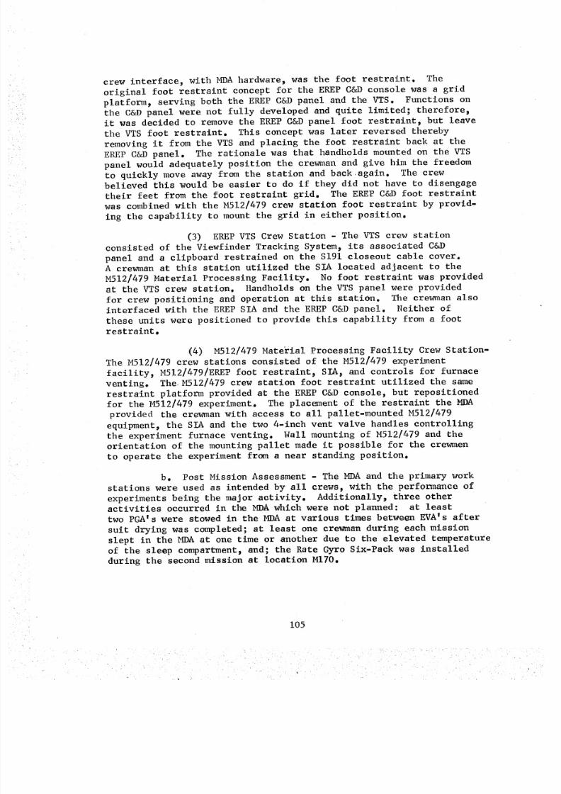
8/8/2019 MSFC Skylab Crew Systems Mission Evaluation
http://slidepdf.com/reader/full/msfc-skylab-crew-systems-mission-evaluation 129/397
crew interface, with MDAhardware, was the foot restraint. Theoriginal foot restraint concept for the EREPC&Dconsole was a gridplatform, serving both the EREPC&Dpanel and the VTS. Functions onthe C&D panel were not fully developed and quite limited; therefore,
it was decided to remove the EREP C&D panel foot restraint, but leave
the VTS foot restraint. This concept was later reversed thereby
removing it from the VTS and placing the foot restraint back at the
EREP C&D panel. The rationale was that handholds mounted on the VTS
panel would adequately position the crewman and give him the freedomto quickly move away from the station and back again. The crewbelieved this would be easier to do if they did not have to disengage
their feet from the foot restraint grid. The EREP C&D foot restraint
was combined with the M512/479 crew station foot restraint by provid-
ing the capability to mount the grid in either position.
(3) EREP VTS Crew Station - The VTS crew station
consisted of the Viewfinder Tracking System, its associated C&D
panel and a clipboard restrained on the S191 closeout cable cover.A crewman at this station utilized the SIA located adjacent to the
M512/479 Material Processing Facility. No foot restraint was provided
at the VTS crew station. Handholds on the VTS panel were provided
for crew positioning and operation at this station. The crewman alsointerfaced with the EREP SIA and the EREP C&D panel. Neither of
these units were positioned to provide this capability from a foot
restraint.
(4) M512/479 Material Processing Facility Crew Station-The M512/479 crew stations consisted of the M512/479 experiment
facility, M512/479/EREP foot restraint, SIA_ and controls for furnace
venting. The M512/479 crew station foot restraint utilized the same
restraint platform provided at the EREP C&D console, but repositionedfor the M512/479 experiment. The placement of the restraint the MDA
provided the crewman with access to all pallet-mounted M512/479
equipment, the SIA and the two 4-inch vent valve handles controllingthe experiment furnace venting. Wall mounting of M512/479 and the
orientation of the mounting pallet made it possible for the crewmen
to operate the experiment from a near standing position.
b. Post Mission Assessment - The MDA and the primary work
stations were used as intended by all crews, with the performance of
experiments being the major activity. Additionally, three otheractivities occurred in the MDA which were not planned: at least
two PGA's were stowed in the MDA at various times between EVA's after
suit drying was completed; at least one crewman during each mission
slept in the MDA at one time or another due to the elevated temperatureof the sleep compartment, and; the Rate Gyro Six-Pack was installed
during the second mission at location MITO.
105
8/8/2019 MSFC Skylab Crew Systems Mission Evaluation
http://slidepdf.com/reader/full/msfc-skylab-crew-systems-mission-evaluation 130/397
The crews performance proved that man can function effectively,
in a cylindrical spacecraft module, in a zero-g environment and
hardware orientation. However, there existed a longer period of
adaptation to working the cylindrical layout of the MDA than in the
floor to ceiling orientation of the OWS. All Skylab crews expressed
a feeling of disorientation when arriving in the MDA, until they
found a familiar piece of experiment hardward to key on. Most crew-
men found that they used the ATM O&D panel or the EREP experiment
hardware to orient themselves in the MDA. It also took the crewmen
longer to locate a particular stowage container in the MDA than in
the OWS, where the stowage containers were installed in a floor to
ceiling arrangement. This suggested that, in future spacecraft, it
would be more efficient to lay out experiment and stowage hardware
in a one--g orientation, even in small cylindrical vehicles like the
MDA'. At the very least, the early design ooncept for small cylindri-
cal vehicles should provide for functional grouping of hardware.
Stowage containers should be grouped in a common direction and area
like the OWS experiment compartment stowage containers, or circumfer-entially in a particular location like the OWS ring lockers.
Each crew considered the volume of the MDA sufficient for working
and hanging onto things, but expressed problems with traffic, when two
crewmen were working in the MDA and a third crewman tried to get past.
The MDA volume was suitable for its designated functions as a multiple
docking adapter for a larger space station and experiments/stowage
module. The volume ideally should be increased for a similar type
module used as a single space station experiments module for a crew
of three.
Comments relative to the ATM C&D crew station were generally
favorable except for the incompatibility of a crewman working at the
ATM C&D panel while another crewman was working at the STS control
and display panels. The layout of the ATM controls and displays isdiscussed in the Controls and Displays section. Foot restraint
platform and chair assessment data is contained in the Mobility/
Stability Aids section. Generally, however, reach envelopes were
considered to be less restricted using the foot restraint platform.
The ATM C&D integral panel lighting emitted a pleasant effect when the
MDA floodlights were off; however_ this was not necessary. When the
floodlights were turned on, the ATM C&D edge lighting effect disap-
peared and when the ATM C&D lights were used along, the checklists
could not be read. There was a general degradation in the bright-
ness of the ATM C&D counter lights with usage.
Comments concerning the EREP C&D crew station were favorable.
The crews saved setup time at the EREP C&D by leaving the communica-
tion cables and eommuniaation carrier (soft caps) connected to theSIA.
A significant deficiency of the EREP VTS crew station was the
lack of a crewmen foot restraint. It is necessary to have a foot
restrain t at all crew stations requiring the crewman to operate
106
8/8/2019 MSFC Skylab Crew Systems Mission Evaluation
http://slidepdf.com/reader/full/msfc-skylab-crew-systems-mission-evaluation 131/397
controls and manipulate charts/checklists for long durations. The
only annoying problem associated with this crew station was with the
clipboard mounted on the EREP experiment S191 eloseout cable cover.
The clipboard, attached to the cable cover by two snaps, was used to
hold checklists, maps, photographs or target sites, etc. and unsnapped
several times when used by the crewman.
The crew operated at the M512/479 Material Processing Facility
crew station as planned and reported no major problems. Temporary
stowage of a PGA near the crewman's head caused minor infringement
of work envelope.
2. AM Crew Station
a. Design Description - The crew stations in the AM were
designed to provide: (i) passage between the MDA and OWS; (2) stow-
age of system and experiment support hardware; (3) primary system
controls; (4) an EVA airlock and (5) EVA support hardware. The
primary AM crew stations were the STS, Lock Compartment, Aft Compart-ment and EVA FAS Workstation which is discussed in the EVA section.
The internal arrangement of the AM is illustrated in Figures 92 and 93.
The equipment in the AM was arranged circumferentially around
the interior with all control panels and individual controls posi-tioned in similar orientations. The crewman's design orientation
throughout the AM was for the body to be parallel to the vehicle's
X-axis with the head aft, the natural position for a crewman as he
translated from the CSM into the AM during activation. AM equipment
modules were designed to offer minimum protuberances into the vehicle's
interior and to provide large radii corners wherever projections could
not be entirely avoided.
(I) STS Crew Station - The STS Crew Station consisted
of the STS C&D panels, system hardware stowage containers, four view-
ing windows, handrails and handrail lights. Because they had thesame diametrical dimensions and were joined directly together, the
STS and MDA were essentially an integral module and often consideredone and the same. This close relationship can be noted from crew
comments which often referred to them interchangeably. To provide
a functionally operable crew station in the STS, agreements had to
be reached across this physical interface. The teleprinter access
door and cabin heat exchanger fire sensors cover which open into the
MDA, and adequate space in the MDA for changing the H20 separator
plates on the condensing heat exchangers are examples of the type of
coordination which was required. In other areas, specifically around
the ATM console as was expected, interferences existed between thesecompartments. The STS was divided into four equipment groups and
arranged to allow space between the containers for access to the STS
windows and equipment inflight maintenance (IFM). An STS window which
provided external viewing was located between each of these equipment
quadrants. The space was sized to be large enough to provide
107
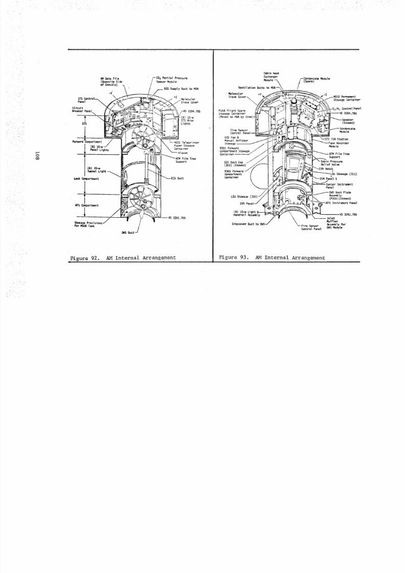
8/8/2019 MSFC Skylab Crew Systems Mission Evaluation
http://slidepdf.com/reader/full/msfc-skylab-crew-systems-mission-evaluation 132/397
• IL
r._
C_
CO
AN Data Ftle(Opposite Sideof Console)
.y"STS Control--_Panel
\
CircuitBr eak er Pa ne l
STS
Forward Con_artment
t (51
P ane l L ig ht s
( 4) 2o ,-wTmlnel
LOck Compartment
Stowage Provisions- / /For M509 Tank
0¢4S Duct
Figure 92. AM Internal
Partial Pressure
Sensor ,Module
Supply Duct to MDA
Cover
-VS 3394.785
IO-w
S TS A re a
Lights
L -M 20 1 T el ep ri nt er
Paper Stowage
Container
Film Tree
Support
Duct
--VS 3241.765
Arrangement
Cabin Heat
Exchanger
Module
Ventilation Ducts
Molecular +y
Sieve _ver_
M168 Flight SpareS to wa ge C on ta in er
(Moved to MDA by Crew)-
(Spare)
Fire Sensor
Contr_)l
E_ Fan &
Manua)
Stowage
M 30 1 F or wa rd
C om pa rt me nt S to wa geContainer
E CS D uc t
(303)
M30S
Compartment
Container
LSU Stowage
EVA Pane
(6) 10-w Light
Handrail Assembly
Crossover Duct toF ir e S en so r
Control Panel
Figure 93. AM Internal Arrangement
Module
PermamentS to wa ge C on ta in er
-DJN 2 C on tr ol Panel
--VS 3394.785
,eaker
(Stowed)
Module
IVA Station
Recorder
Module
Film Tree
Support
Cabin Pressure
R el ie f Val ve
Hatch
S to wa ge ( 31 1)/
EVA Panel 1
Instrument
Panel
Vent Plate
Assen_oly(M326)(Stowed)
Instrument Panel
--VS 3241.765
Inlet
Muffler
Assembly f orOWS Module
8/8/2019 MSFC Skylab Crew Systems Mission Evaluation
http://slidepdf.com/reader/full/msfc-skylab-crew-systems-mission-evaluation 133/397
adequate access for a crewman with ancillary equipment such as cameras,
sextants or other optical viewing devices, yet small enough that
sufficient body restraint could be obtained by bracing between the
adjacent equipment surfaces, thus allowing two-handed tasks to be
performed. The groupings were also planned such that each module had
at least one side exposed to an access space for entrance into theinterior of a module through a removable cover. Additional access
was provided through hinged doors on the front of the equipment, suchas the doors on the mol sieve covers through which the replacement of
solids traps and/or mol sieve fans was accomplished. Handrails and
handrail lights were installed at strategic locations as a protection
and aid for the crew during translations. A handrail type lamp which
provided a 360 ° , non-glare light source was used. A sufficient butminimal number of units were utilized to provide an adequate illumin-
ation level for the required inflight operations to be performed.
Placement and arrangement of the lamps provided an even and consistent
lighting level throughout the compartment, including the recessed
areas between the equipment quadrants. As a safety precaution, it
was not considered desirable to bring the unprotected, raw power lines
into the vehicles interior where they would be exposed to an oxygen-
rich atmosphere. To preclude this, the circuit breaker panels were
designed to penetrate the AM pressure wall. Using this method, the
cables from the primary power source were left on the outside of the
spacecraft and the lines on the inside were protected by circuitbreakers. The Forward Compartment served as an extension of the STS
and contained equipment ancillary to that crew station purposes.
The operational units in the Forward Compartment were the AM tape
recorder module and the klaxon for the Caution and Warning System;
the other two units were stowage containers with IFM spares. No
control panels or lights were present in this compartment. The
klaxon was located behind the opened AM forward internal hatch. Thislocation was selected so that the hatch would act as an audio baffle
for this siren and provide aural protection for a crewman should he
be nearby when it was energized.
(2) Lock Compartment Crew Station - The Lock Compart-
ment Crew Station consisted of the EVA hatch, two internal hatches,
two redundant EVA control panels, two film tree receptacles, and
lock compartment control panel and valves. It was originally intended
to use the Lock Compartment solely for EVA support, but later decided
to use the Aft Compartment as an extension. The equipment required
for EVA's was located in the Lock Compartment near the EVA Hatch for
convenience. The control panels had the same orientation as those
in the STS. AM lighting is discussed in detail in the Illumination
section.
Spherical stowage containers for the Life Support Umbilical
(LSUs) were on the exterior of the vehicle and presented only a round
opening to the interior. The LSU sphere covers were used for launch
109
8/8/2019 MSFC Skylab Crew Systems Mission Evaluation
http://slidepdf.com/reader/full/msfc-skylab-crew-systems-mission-evaluation 134/397
restraint of the LSUconnectors and were temporarily stored in theaft compartment for EVA. No internal volume was consumedfor thisfunction and no physical obstructions were created by it.
(3) Aft CompartmentWork Station - Besides acting asan extension for the Lock Compartment, the Aft Compartmentcontainedthe facility for recharing the M509Experiment propulsion supplybottle and access to the OWSHeat Exchangermodule. To avoid aphysical obstruction in this area, the M509recharge assembly_whichheld the bottle during recharge_ was designed to be folded-up whennot in use.
b. Post Mission Assessment - The AMand the primary workstations were used as intended by all crews. Additionally, two otheractivities occurred in the AMwhich were not planned: (i) servicingthe coolant loop in the STSand; (2) stowage of additional supportequipment in the Lock Compartmentfor several contingency EVA
activities.The Skylab crews indicated that the arrangement of AMcrew sta-tion equipment was very satisfactory. The radial arrangement,orientation, and grouping of the control panels in the STSwas conven-ient and worked well. Information concerning the inadvertent trippingof circuit breaker switches by the crewmen,while translating throughthe STS_is contained in the Controls and Displays section.
The STSwindows proved to be of greater value than had beenexpected. They worked well for the planned events such EVAcoordin-ation, attitude correlation, external structure inspection, spaceviewing and Earth viewing. In addition_ they were invaluable for theunscheduled events such as deployment of the sun shades, SASdeploy-ment and later to periodically monitor the condition and orientationof the thermal shields. The inside surface of the STSwindows on theshade side sometimes fogged up with the cover open. The fog dispersedshortly after the cover was closed. The STSwindow covers becamedifficult to operate. Onecover would not close completely; never-theless, the windowwas still being totally covered.
The access provided inside the mol sieve covers for servicingthe H20separator plates was more than adequate. This was an areawhich had been difficult to simulate in one-g but worked satisfactor-ily during flight.
The crewmanoperating the ATMconsole interferred with othercrewmentranslating through the vehicle or working in the STScompart-ment. Since the ATMC&Dposition was occupied for extensive periods
of time, this interference was an annoyance.The design and arrangement of the handrails in the AMwere good_although there were insufficient crewmanrestraints available toperform the unscheduled servicing of the coolant loop.
The volume of the lock compartment for EVApreparations andoperations was acceptable. The compartment was large enough to
ii0
8/8/2019 MSFC Skylab Crew Systems Mission Evaluation
http://slidepdf.com/reader/full/msfc-skylab-crew-systems-mission-evaluation 135/397
accommodate the equipment and crew, yet small enough to provide
adequate body restraint. The functional usage arrangement of the
equipment in the lock compartment was well designed. The ease withwhich the LSUs were removed from and returned to stowage was partic-
ularly noticed.
The operations of the hatch mechanisms and repressurization valveswere very smooth. During crew translations, the internal hatch sills
were "knee bumpers" if the trajectory was not perfect. The sill
visible from the airlock, the opening from the STS, and the forward
side of the forward hatch had not been protected.
3. OWS Crew Station
a. Design Description - The crew stations in the OWS were
designed to provide: (i) primary crew quarters and habitation equip-
ment; (2) stowage of hardware and experiment support equipment;
(3) stowage of crew equipment and consumables; (4) OWS systems
control and displays; and (5) volume for the performance of experi-
ments. The OWS crew stations were the Forward Compartment, Wardroom,Waste Management Compartment, Sleep Compartment, Experiment Compart-
ment, and Plenum Area and are illustrated in Figure 94. The equip-
ment in the OWS was installed on compartment walls, floors, and ceil-
ings and was primarily arranged in a vertical or circumferential
one-g orientation. This arrangement was possible because of the open
grid floors dividing the lower crew quarters from the plenum area
and the forward compartment.
(I) Forward Compartment Crew Station - The forward
compartment was the largest of all crew occupied areas in the entire
cluster. Equipment located in the forward compartment were the WMC
ventilation fan, food freezers, refrigeration pump unit, ventilation
ducts, fans and mixing chamber, biocide monitoring equipment, scient-
ific airloeks, miscellaneous lockers and stowage provisions, film
vault and photographic equipment, ring containers (for large volume
stowage items) and the large food containers. Also stowed and operatedin the forward compartment were the hardware items associated with
the various scientific, technical and medical experiments .
(2) Wardroom Crew Station - The Wardroom was a
"pie-shaped" compartment on the crew quarters level. Facilities in
this crew station included a galley, food freezer and chiller_ food
table, viewing window, experiment equipment, crew entertainment
center, plus stowage compartments for flight data, clothing and other
supplies. Figure 95 illustrates the general arrangement and isyoutof the Wardroom.
(3) Waste Management Crew Station - The WMC was a
compact rectangular room located at the crew quarters level. This
iii
8/8/2019 MSFC Skylab Crew Systems Mission Evaluation
http://slidepdf.com/reader/full/msfc-skylab-crew-systems-mission-evaluation 136/397
i i|
• WARDROOM -'-_ _r-- WASTET _i, _ MANAGEMENT
FO_AROO_ARO \ \COMPARTMENT_ COMPARTMENT _i _ -Z
__ QUARTERS"%,""_llt I1_ "Y
FORWAR°OMPARTMENTl_T_FLOOR_ _ _ r /EXPERIMENT _ %. I /
CEILING COMPAR T-MENT J__._/_
HABITATIONAREA
-F-CREWQUAR TER £
• I ....
Figure 94.
I '10101
OWS Basic Layout and _rangement
/ -SLEEP
__ +Z COMPARTMENTCREW QUARTERS(VIEW LOOKI NG AFT)
PLENUM AREA
,'-'-- HABITATION AREA/WASTE TANKBULKHEAD
,--CEILING EGRESS OPENING
rSTOWAG E P---INTERCOM STATIONLOCKER /
/ _ WINDOW
!'TT_"I-_ _/_i'_ /---FOOD CHILLER/
..J'l I I. / ! /_ ""___-... FREEZERS
i<_-.--r_lTf(,-J_'r--i_ _--_ _ _,_l-_'_FJ'l]1_"'_ GENERALI= /IL.,..L___I-r|--_ -_IE__jI_ L:_ i / " ILLUMINATIONI /11' I' _/, _ I _II_._LE_ / I LIGHT FIXTURE
/tI_/_ _! _ I_. i | ! (TYP4PLCS) ""% _..._-'_"_n
FLIGHT DATA F LE
FLOOR EGRESS OPENING
"_L__'E_NT_R___IOONDAGEMENT__,_ V,EV_/ b-IJTBOARD "_ G_/_LLE_!._:._- LOOKING TABLE
_ i'_ _ "_ _ III,IITYT (__E_ANC_E
.,q...,_"%_. ,__ ..L'--IIJ_ JLJ_I r;_-q I_'1 I I STOWAGE J_/____J L_JL_.JJ ENTRANCE_'_T_ _XI III '_,1 I ILJ LJ L4 CABINETJ | ,, ..... _f..7 CURTAIN $....1
O_TBOAR_I_' _ I1__ I _11 '_°_'_--
/_ _ _i. i'_ WARDROOM PLAN VI"
QUARTERS
FLgure 9.5. Wacdroom l.ayout a_d Arcangeme_t
i12
8/8/2019 MSFC Skylab Crew Systems Mission Evaluation
http://slidepdf.com/reader/full/msfc-skylab-crew-systems-mission-evaluation 137/397
VIEW LOOKING TOWARD WARDROOM WALL
WARDROOMAL ..;-_...._..._
I 1 L
L LOCKERRYINGAREA
--TELEPHONE BOOTHSTYLE DOOR(ENTRANCE)
Figure 96. WMC
FWMC cSLEMEPARM ENT"_ _r
-- __j._l CORNER ___.,.J-_.-/j/ STOWAGE WMC_r J II
GENERAL LI_i ILLUMINATION _] IJ
HOLDING I I-_'-[)lr-_F _t_]7,COMPARTMENT IIEl '
COLLECTOR"_,IE __ _._:_---
PROCESSOR _ _MOOULEURINE J#'_"-- __.J... . /i "FREEZER_'_ _ - _
VIEW LOOKING TOWARD SLEEP COMPARTMENT WALL
Layout and Arrangement
I_WMC CEILING
HANDRAIL
STOWAGEOCKER(_ERSONALYG'ENE
II ,TEMS_HANDWASHER
L,_" FIX ED LIGHT
II DUTYFOOT
RESTRAINTS
II _SLEEP
]_r COMPARTMENTLL- WALL
ENTRANCE
INBOARD
/_ _"--SLEEP
_COMPARTMENT
QUARTERS
i]L.J I_ -- PRIVACY
LIGHT BAFFLES /_
INSTALLED ON / l
CEILING AS REQUIRED'-_ _
SLEEP • _ft_'_'_ "__
R_STRAIN T .,_T_ ,_._j
PRIVACY , "_x '
m r_,,o
SLEEPCOMPARTMENT
CORRIDOR_ __ _
CURTAINS
CE IL IN G E GR ESS ,t'
_/,. OPENING /
__ ENTRANCE""_ H_i"_'F.X_TII
_ CORNER STOWAGE
CABINETINTERCOM STATION
/(TYP 3 PLCS)
_ _, _FLOOR
_;_ _ /EGRESS,_ OPENING
;_ " _ GENERAL
_P'_ _k_/ ILLUMINATION":'-'_ _ _ LIGHT FIXTURE
.VIEW _" SLEEP RESTRAINT
(TYP 3 PLCS)
PLAN
TOWAGE LOCKERS
FLOOR EGRESS OPENING (COVERED)
V IE W L OO KI NG INBOARD
Figure 97. Sleep Compartment Layout and Arrangement
113
8/8/2019 MSFC Skylab Crew Systems Mission Evaluation
http://slidepdf.com/reader/full/msfc-skylab-crew-systems-mission-evaluation 138/397
CEILINGEGRESS
REMOTE CONTROL _-OPENING PORTABLE
WARDROOM AND WMC _ RESTRAINTSLIGHTING PANEL _ TEMPORARY
; 630 ._I_. _ _ STOWAGEIRE FIRE
EXTINGUISHER_ EXTINGUISHER
--ELECTRICAL
INITIAL CONTROLCONSOLE
ENTRY AND -- EXPERIMENT
EMERGENCY _ COMPARTMENT/--GENERAL ILLUMINATION
LIGHT PLCS)---1 I LIGHT FIXTURE (TYP14 PLCS) '(TYP 4/
_ __ STOWAGE LOCKER ,
i,_, _ _ .
0 L-:"; : .. L
__TRASH DISPOSAL AIRLOCK
Figure 98. Experiment Compartment Layout and Arrangement| i =
III
COMMON .,I \\\,, : !/
Figure 99. Plenum Bag Installation
114
8/8/2019 MSFC Skylab Crew Systems Mission Evaluation
http://slidepdf.com/reader/full/msfc-skylab-crew-systems-mission-evaluation 139/397
crew station contained the urine/fecal collection equipment, a H20
dispenser for washing, a washcloth squeezer, stowage lockers for wash-
cloths, towels, wipes and tissues, waste processors, a urine freezer,
towel and washcloth drying provisions, and supplies necessary for
waste management including urine bags, hoses, receivers, sample bags,
fecal bags, etc. The latter items were located in lockers and dis-
pensers within the WMC with resupplies located throughout the OWS.
Figure 96 illustrates the general arrangement and layout of the WMC.
(4) Sleep Crew Station - The three sleep areas were
located in the sleep compartment on the crew quarters level, provided
each crewman with individual sleeping quarters, which contained a
sleep restraint, light, stowage lockers, SIA, and towel holders, The
SPT's sleep area was provided with sleep monitoring devices, equipment
associated with Experiment M133. These three areas comprised the
smallest crew-occupied compartment. An illustration of the general
arrangement and layout of the Sleep Compartment is shown in Figure 97.
(5) Experiment Compartment Crew Station - The experi-ment compartment had an approximate semicircular floor plan and was
the largest volume crew station on the crew quarters level. It
contained the trash airlock, numerous medical experiment devices,
shower, and the OWS electrical control panels. A hexagonal opening
to the Forward Compartment was directly forward of the trash airlock.
Entry to the Wardroom, WMC and Sleep Compartment were available from
the Experiment Compartment. A folding metal door was installed atthe entrance to the WMC and fabric closures were installed at the
Wardroom and Sleep Compartment entrances. An illustration of the
general arrangement and layout of the experiment compartment is
provided by Figure 98.
(6) Plenum Crew Stations - The plenum area was an
irregular shaped area between the crew quarters floor and common
bulkhead (waste tank) and provided volume for permanent stowage of
biologically inactive (inert) trash. The stowage concept utilized
armalon "plenum" bags stowed as illustrated in Figure 99.
b. Post Mission Assessment - The Forward Compartment was
used for performance of experiments, stowage of equipment, pre and
post EVA, as well as unscheduled exercise, recreational aerobatics, andgymnastics. Experiments that required the use of a SAL were restricted
to the -Z SAL because the +Z SAL was used to deploy the parasol and
the modified T027 canister was left in place throughout the mission.
The most significant fact about the large volume is that it did notpresent any difficulty to the crews in terms of translation or
mobility, and more than adequately served the performance and evalu-ation needs of the M509 and TO20 flying experiments. The mass of the
film vault doors and drawers proved troublesome and required the
115
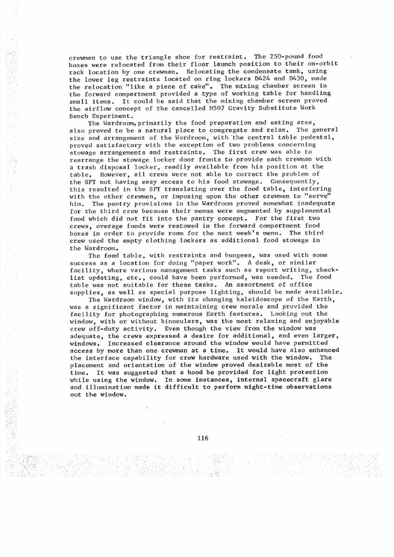
8/8/2019 MSFC Skylab Crew Systems Mission Evaluation
http://slidepdf.com/reader/full/msfc-skylab-crew-systems-mission-evaluation 140/397
crewmen to use the triangle shoe for restraint. The 250-pound food
boxes were relocated from their floor launch position to their on-orbit
rack location by one crewman. Relocating the condensate tank, using
the lower leg restraints located on ring lockers D424 and D430, made
the relocation "like a piece of cake". The mixing chamber screen in
the forward compartment provided a type of working table for handling
small items. It could be said that the mixing chamber screen proved
the airflow concept of the cancelled M507 Gravity Substitute Work
Bench Experiment .The Wardroom, primarily the food preparation and eating area,
also proved to be a natural place to congregate and relax. The general
size and arrangement of the Wardroom, withthe central table pedestal,
proved satisfactory with the exception of two problems concerning
stowage arrangements and restraints. The first crew was able to
rearrange the stowage locker door fronts to provide each crewman with
a trash disposal locker, readily available from his position at the
table. However, all crews were not able to correct the problem of
the SPT not having easy access to his food stowage. Consequently,this resulted in the SPT translating over the food table, interfering
with the other crewmen, or imposing upon the other crewmen to "serve"
him. The pantry provisions in the Wardroom proved somewhat inadequate
for the third crew because their menus were augmented by supplemental
food which did not fit into the pantry concept. For the first two
crews, overage foods were restowed in the forward compartment food
boxes in order to provide room for the next week's menu. The third
crew used the empty clothing lockers as additional food stowage inthe Wardroom.
The food table, with restraints and bungees, was used with some
success as a location for doing "paper work". A desk, or similar
facility, where various management tasks such as report writing, check-
list updating, etc., could have been performed, was needed. The foodtable was not suitable for these tasks. An assortment of office
supplies, as well as special purpose lighting, should be made available.
The Wardroom window, with its changing kaleidoscope of the Earth,
was a significant factor in maintaining crew morale and provided the
facility for photographing numerous Earth features. Looking out the
window, with or without binoculars, was the most relaxing and enjoyable
crew off-duty activity. Even though the view from the window was
adequate, the crews expressed a desire for additional, and even larger,
windows. Increased clearance around the window would have permitted
access by more than one crewman at a time. It would have also enhanced
the interface capability for crew hardware used with the window. The
placement and orientation of the window proved desirable most of thetime. It was suggested that a hood be provided for light protection
while using the window. In some instances, internal spacecraft glareand illumination made it difficult to perform night-time observations
out the window.
116
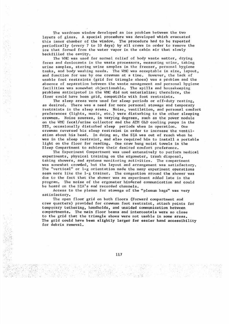
8/8/2019 MSFC Skylab Crew Systems Mission Evaluation
http://slidepdf.com/reader/full/msfc-skylab-crew-systems-mission-evaluation 141/397
The wardroom window developed an ice problem between the two
layers of glass. A special procedure was developed which evacuated
this inner chamber of the window. The procedure had to be repeated
periodically (every 7 to I0 days) by all crews in order to remove the
ice that formed from the water vapor in the cabin air that slowly
backfilled the cavity.
The WMC was used for normal relief of body waste matter, drying
feces and desiccants in the waste processors, measuring urine, taking
urine samples, storing urine samples in the freezer, personal hygiene
tasks_ and body washing needs. The WMC was acceptable in size, layout,
and function for use by one crewman at a time. However, the lack of
usable foot restraints (grid for triangle shoes) was a problem and the
absence of separation between the waste management and personal hygiene
facilities was somewhat objectionable. The spills and housekeeping
problems anticipated in the WMC did not materialize; therefore, the
floor could have been grid, compatible with foot restraints.
The sleep areas were used for sleep periods or off-duty resting,
as desired. There was a need for more personal stowage and temporary
restraints in the sleep areas. Noise, ventilation, and personal comfort
preferences (lights, music, etc.) were disturbing to the other sleeping
crewmen. Noise sources, in varying degrees, such as the power module
on the WMC fecal/urine collector and the ATM C&D cooling pumps in the
STS, occasionally disturbed sleep periods when in operation. One
crewman reversed his sleep restraint in order to increase the ventil-
ation about his head. In doing so, the SIA was out of reach when he
was in the sleep restraint, and also required him to install a portable
light on the floor for reading. One crew hung moist towels in the
Sleep Compartment to achieve their desired comfort preference.
The Experiment Compartment was used extensively to perform medical
experiments, physical training on the ergometer, trash disposal,
taking showers, and systems monitoring activities. The compartment
was somewhat crowded, but the layout and arrangement was satisfactory.
The "vertical" or l-g orientation made the many experiment operations
seem more like the l-g trainer. The congestion around the shower was
due to the fact that the shower was an experiment added late in the
program. The noise of the ergometer hindered communication and could
be heard on the SIA's and recorded channels.
Access to the plenum for stowage of the "plenum bags" was very
satisfactory.
The open floor grid on both floors (Forward compartment and
crew quarters) provided for crewman foot restraint, attach points for
temporary tethering, handholds, and unaided communication between
compartments. The main floor beams and intercostals were so close
to the grid that the triangle shoes were not usable in some areas.
The grid could have been slightly larger for easier hand accessibility
for debris removal.
117
8/8/2019 MSFC Skylab Crew Systems Mission Evaluation
http://slidepdf.com/reader/full/msfc-skylab-crew-systems-mission-evaluation 142/397
K. Mobility-Stability Aids
Mobility-stability aids were provided throughout the Skylabcluster to assist the crews in translating to and from work stations
and for restraint, while performing various mission tasks. Mobility-
stability aids included fixed devices, which were preinstalled for
specific operations, and portable restraints, which could be installed
by the crew at a variety of work stations. In addition to these aids,there were numerous items of equipment located throughout the cluster
which could serve as mobility-stability aids, although that was not
their primary function.
I. Design Description
a. Fixed Aids
(I) Fixed Handrails and Handholds - Fixed handrails
and handholds were preinstalled throughout the cluster to assist thecrewmen in translation and to assist them in maintaining temporary
body stability in activity areas. Figure I00 illustrates the fixed
mobility-stability aids within the entire Skylab vehicle. The hand-
rails, around the _A hatches, were the only mobility aid provisionsin the MDA.
(2) WMC Foot Restraints - WMC foot restraints were
provided to enable the crewmen (while barefooted, stocking-footed, or
wearing soft boots) to use the urine collector and handwasher, and to
perform various hygiene and maintenance tasks with both hands free.These restraints were mounted on the WMC floor and were adjustable to
accommodate various foot sizes. This concept is shown by Figure i01.
(3) Fireman's Pole - A fireman's pole was provided inthe OWS forward area to assist the crewmen in translating from the
OWS access hatch to the Forward Compartment floor and is i llustrated
in Figure i00. The fireman's pole was launched in it's stowage
location, then assembled and installed in it's use location on-orbit.
A fireman's pole was not provided in the MDA because of the proximityof the hardware.
(4) Food Table Restraints - Each of the three food
table eating stations were provided with foot and thigh restraints as
illustrated in Figure 102. The foot restraints, comprised of two
adjustable foot restraint straps, were designed to be used barefoot,
in stocking feet, or while wearing soft boots. Triangle shapedopenings were also provided to accommodate the triangle shoes.
The thigh restraints were attached to the upper portion part of
the food table pedestal and provided the crewmen s means of stabiliza-
tion in a semi-seated position while eating. These restraints were
fric_on hinged at the table to permit elevation selection and out-of-
the way stowage for access to the food table pedestal doors, and
at the midpoint, to provide selection of the desired seating position.
118
8/8/2019 MSFC Skylab Crew Systems Mission Evaluation
http://slidepdf.com/reader/full/msfc-skylab-crew-systems-mission-evaluation 143/397
ATM C& O CONS OLE
HANDRAIL
FI LM VA ULTHANDHOLDS
M§I Z,/M,479 HANDHOLD _
INTERI OR AND _,,,,L
EXTERIOR _HATCH HANGHOLOS " .,_,_
( TYP Z DOCK ING AND 3 / IBULKHEAD HATCH ES)--._ \.
VIEWFINDER ..f. ,'''''%
HANDHOLO--_ /
0OCKING PORT /
SEGMENTED HANDRAIL_
(TYP 2 PORTSI --/
HANDRAIL
TYPI_ _Vlf- HAN DWA.SHER H-ANDHOLO
/HANDRAIL --
I, /,,,
HANDRAI LS ARE MOUNTED _ _ _,l _' [i
ON PANELS & STOWAGE _ _ "_L '**_ _,CONTAINERS IN THE STS _ _ ' '
' E VA HAT
_,__.._ HANOHOLO -J I_,___ L_. FI RE MA NS POLE
_,,,.r_ (REMOVABLE AND
_ COLLAPSIBLE|
_'_UTTON) _,:_
FIREMANS POLE DETAIL _"_'_"_"_
Figure i00. Handrail Restraints
AFT C _ P.IleT
HANORAIL
_y +Z
_" ELECTRICAL
W'MC CEILING CONTROL
HANDRAIL CONSULEHANDRAlU (4)
NOTE: ALL HANDRAILS AND FIXED HANDHOLDS ARE COLORED BLUE
J
ADJUSTABLEV ELCO AT' r A CHE :
Figure i01. Foot Restraint-Fixed
119
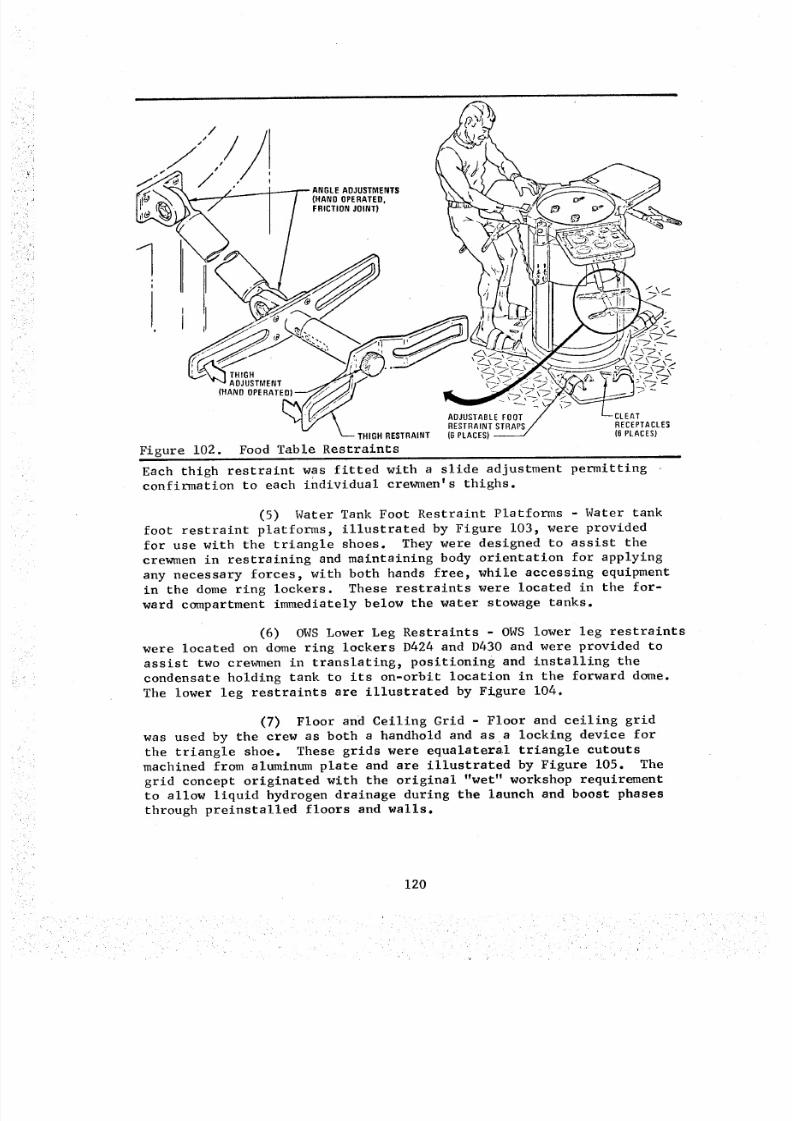
8/8/2019 MSFC Skylab Crew Systems Mission Evaluation
http://slidepdf.com/reader/full/msfc-skylab-crew-systems-mission-evaluation 144/397
ENTS(HANDOPERATED,FRICTIONJOINT)
THIGHADJUSTMENT
(HANDOPERATE
THIGHRESTRAINT
Figure 102. Food Table Restraints
ADJUSTABLEFOOTRESTRAINT STRAPS(B PLACES)--
CLEATRECEPTACLES(6 PLACES)
Each thigh restraint was fitted with a slide adjustment permittingconfirmation to each individual crewmen's thighs.
(5) Water Tank Foot Restraint Platforms - Water tank
foot restraint platforms, illustrated by Figure 103, were provided
for use with the triangle shoes. They were designed to assist the
crewmen in restraining and maintaining body orientation for applying
any necessary forces, with both hands free, while accessing equipment
in the dome ring lockers. These restraints were located in the for-
ward compartment immediately below the water stowage tanks.
(6) OWS Lower Leg Restraints - OWS lower leg restraints
were located on dome ring lockers D424 and D430 and were provided to
assist two crewmen in translating_ positioning and installing the
condensate holding tank to its on-orbit location in the forward dome.
The lower leg restraints are illustrated by Figure 104.
(7) Floor and Ceiling Grid - Floor and ceiling grid
was used by the crew as both a handhold and as a locking device forthe triangle shoe. These grids were equalateral triangle cutouts
machined from aluminum plate and are illustrated by Figure 105. The
grid concept originated with the original "wet" workshop requirement
to allow liquid hydrogen drainage during the launch and boost phases
through preinstalled floors and walls.
120
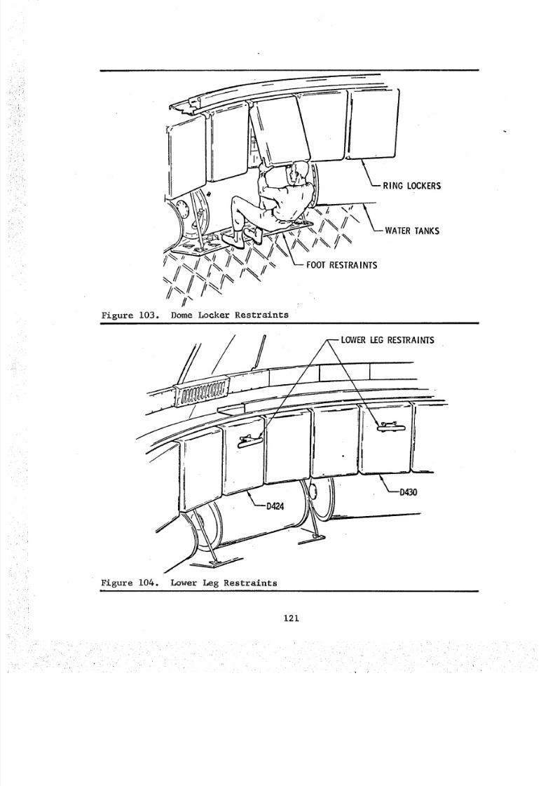
8/8/2019 MSFC Skylab Crew Systems Mission Evaluation
http://slidepdf.com/reader/full/msfc-skylab-crew-systems-mission-evaluation 145/397
Figure 103. Dome Locker Restraints
/ LOWERLEGRESTRAINTS
Figure 104. Lower Leg Restraintsi
121
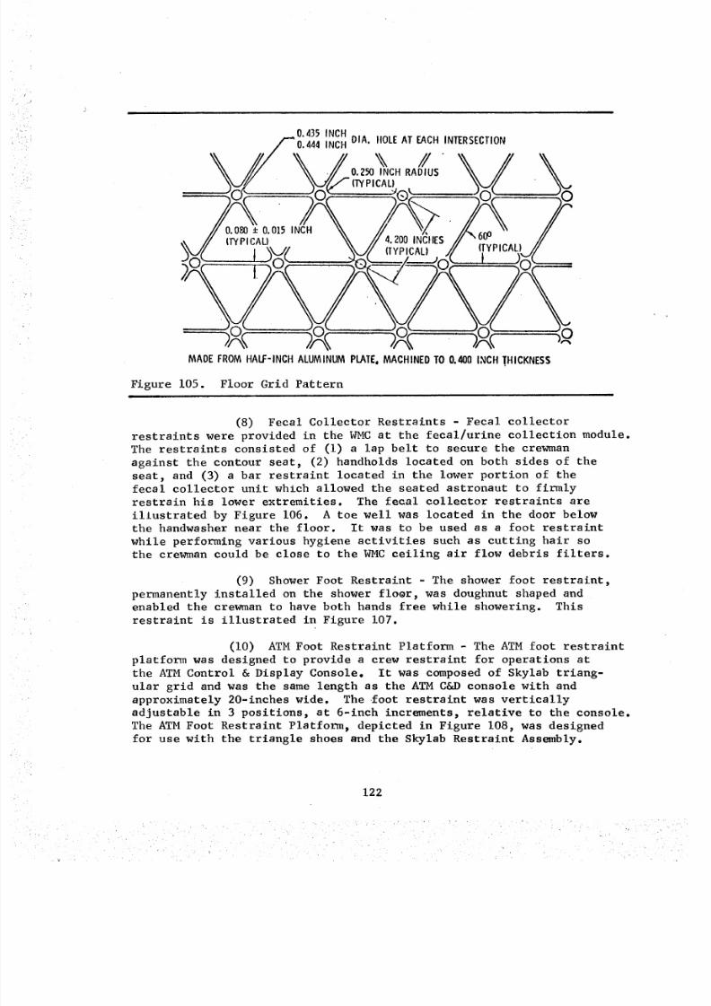
8/8/2019 MSFC Skylab Crew Systems Mission Evaluation
http://slidepdf.com/reader/full/msfc-skylab-crew-systems-mission-evaluation 146/397
0 435 INCH
0'444INCH DIA. IIOLE AT EACH INTERSECTION
O; (O ...... J®_ "JO _" JO
_N . r',', . . ._.:_L_.___.l.___.jr_. v _r_L--__-.t "" " '-' "
0 0 0 0 )0
MADEFROM HALF-INCH ALUMINUM PLATE,MACHINEDTO 0.400 INCH THICKNESS
Figure 105. Floor Grid Pattern
(8) Fecal Collector Restraints - Fecal collector
restraints were provided in the WMC at the fecal/urine collection module.
The restraints consisted of (i) a lap belt to secure the crewman
against the contou_ seat, (2) handholds located on both sides of the
seat, and (3) a bar restraint located in the lower portion of thefecal collector unit which allowed the seated astronaut to firmly
restrain his lower extremities. The fecal collector restraints are
illustrated by Figure 106. A toe well was located in the door belowthe hsndwasher near the floor. It was to be used as a foot restraint
while performing various hygiene activities such as cutting hair sothe crewman could be close to the WMC ceiling air flow debris filters.
(9) Shower Foot Restraint - The shower foot restraint,
permanently installed on the shower floor, was doughnut shaped and
enabled the crewman to have both hands free while showering. This
restraint is illustrated in Figure 107.
(I0) ATM Foot Restraint Platform - The ATM foot restraint
platform was designed to provide a crew restraint for operations atthe ATM Control & Display Console. It was composed of Skylab triang-
ular grid and was the same length as the ATM C&D console with and
approximately 20-inches wide. The foot restraint was vertically
adjustable in 3 positions, at 6-inch incroments_ relative to the console.
The ATM Foot Restraint Platform_ depicted in Figure 108, was designed
for use with the triangle shoes and the Skylab Restraint Assembly.
122
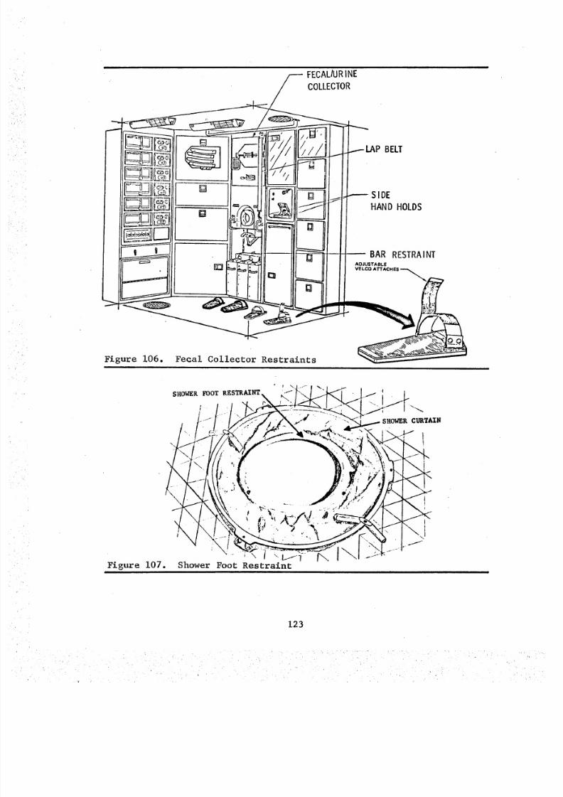
8/8/2019 MSFC Skylab Crew Systems Mission Evaluation
http://slidepdf.com/reader/full/msfc-skylab-crew-systems-mission-evaluation 147/397
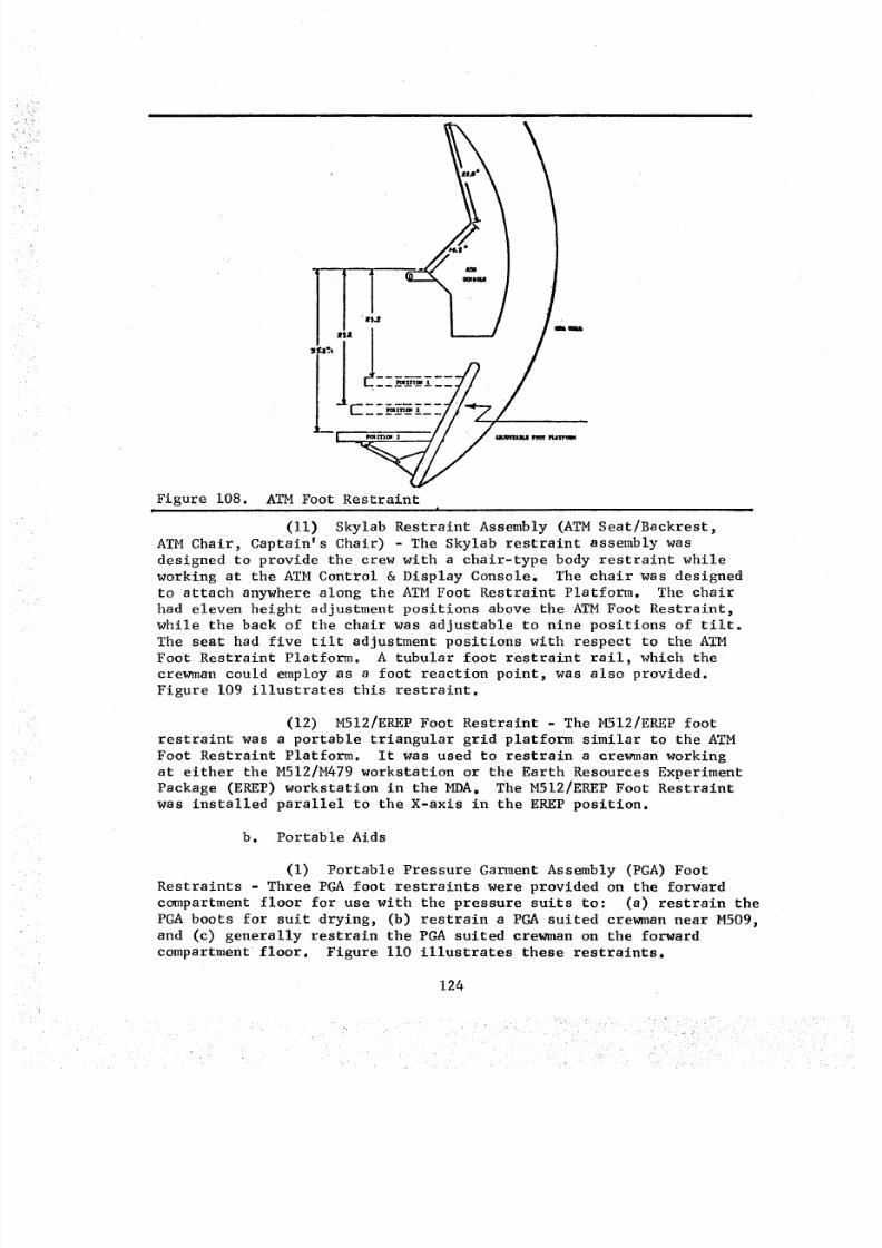
8/8/2019 MSFC Skylab Crew Systems Mission Evaluation
http://slidepdf.com/reader/full/msfc-skylab-crew-systems-mission-evaluation 148/397
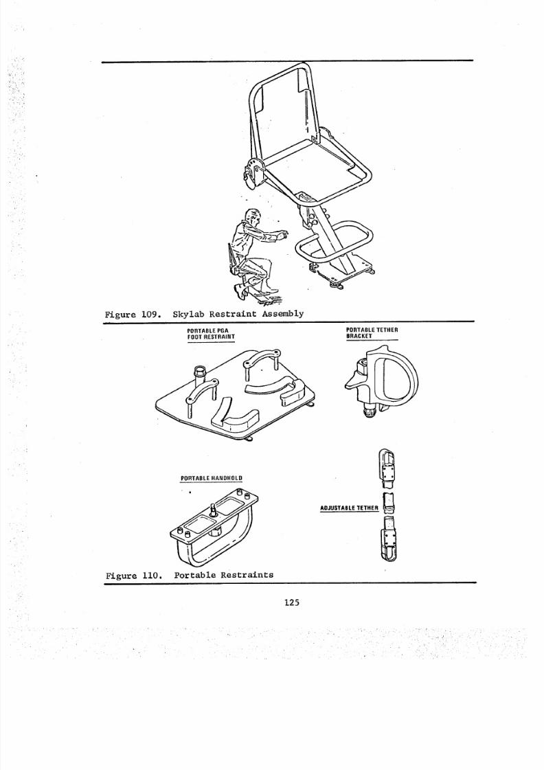
8/8/2019 MSFC Skylab Crew Systems Mission Evaluation
http://slidepdf.com/reader/full/msfc-skylab-crew-systems-mission-evaluation 149/397
Figure 109.
Figure ii0.
Skylab Restraint Assembly
PORTABLE PGA PORTABLE TETHERFOOT RESTRAINT BRACKET
<PORTABLE HANDHOLD
Portable Restraints
ADJUSTABLE TETHER
125
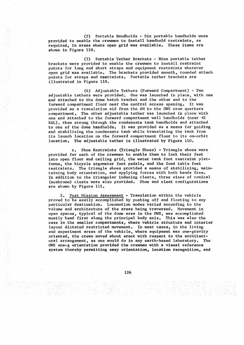
8/8/2019 MSFC Skylab Crew Systems Mission Evaluation
http://slidepdf.com/reader/full/msfc-skylab-crew-systems-mission-evaluation 150/397
(2) Portable Handholds - Six portable handholds wereprovided to enable the crewmento install handhold restraints, as
required_ in areas where open grid was available. These items are
shown in Figure ii0.
(3) Portable Tether Brackets - Nine portable tether
brackets were provided to enable the crewmen to install restraint
points for long and short straps and equipment restraints wherever
open grid was available. The brackets provided smooth, rounded attach
points for straps and restraints. Portable tether brackets are
illustrated in Figure ii0.
(4) Adjustable Tethers (Forward Compartment) - Two
adjustable tethers were provided. One was launched in place, with one
end attached to the dome hatch bracket and the other end to the
forward compartment floor near the central access opening. It was
provided as a translation aid from the AM to the OWS crew quarters
compartment. The other adjustable tether was launched in place withone end attached to the forward compartment wall handholds (near +Z
SAL), then strung through the condensate tank handholds and attached
to one of the dome handholds. It was provided as a means for guiding
and stabilizing the condensate tank while translating the tank from
its launch location on the forward compartment floor to its on-orbit
location. The adjustable tether is illustrated by Figure ii0.
c. Shoe Restraints (Triangle Shoes) - Triangle shoes were
provided for each of the crewmen to enable them to lock their feet
into open floor and ceiling grid, the water tank foot restraint plat-
forms, the bicycle ergometer foot pedalsp and the food table foot
restraints. The triangle shoes provided a means of stabilizing, main-
taining body orientation, and applying forces with both hands free.
In addition to the triangular indexing cleats, three sizes of conical
(mushroom) cleats were also provided. Shoe and cleat configurations
are shown by Figure iii.
2. Post Mission Assessment - Translation within the vehicle
proved to be easily accomplished by pushing off and floating to any
particular destination. Locomotion modes varied according to thevolume and architecture of the areas being traversed. Movement in
open spaces, typical of the dome area in the OWS, was accomplished
mostly head first along the principal body axis. This was also the
case in the smaller compartments, where vehicle structure and interior
layout dictated restricted movement. In most cases, in the livingand experiment areas of the vehicle, where equipment was one-gravity
oriented, the crews moved about erect with respect to the architect-
ural arrangement, as one would do in any earth-based laboratory. The
OWS one-g orientation provided the crewman with a visual reference
system thereby permitting easy orlentation_ location recognition, and
126
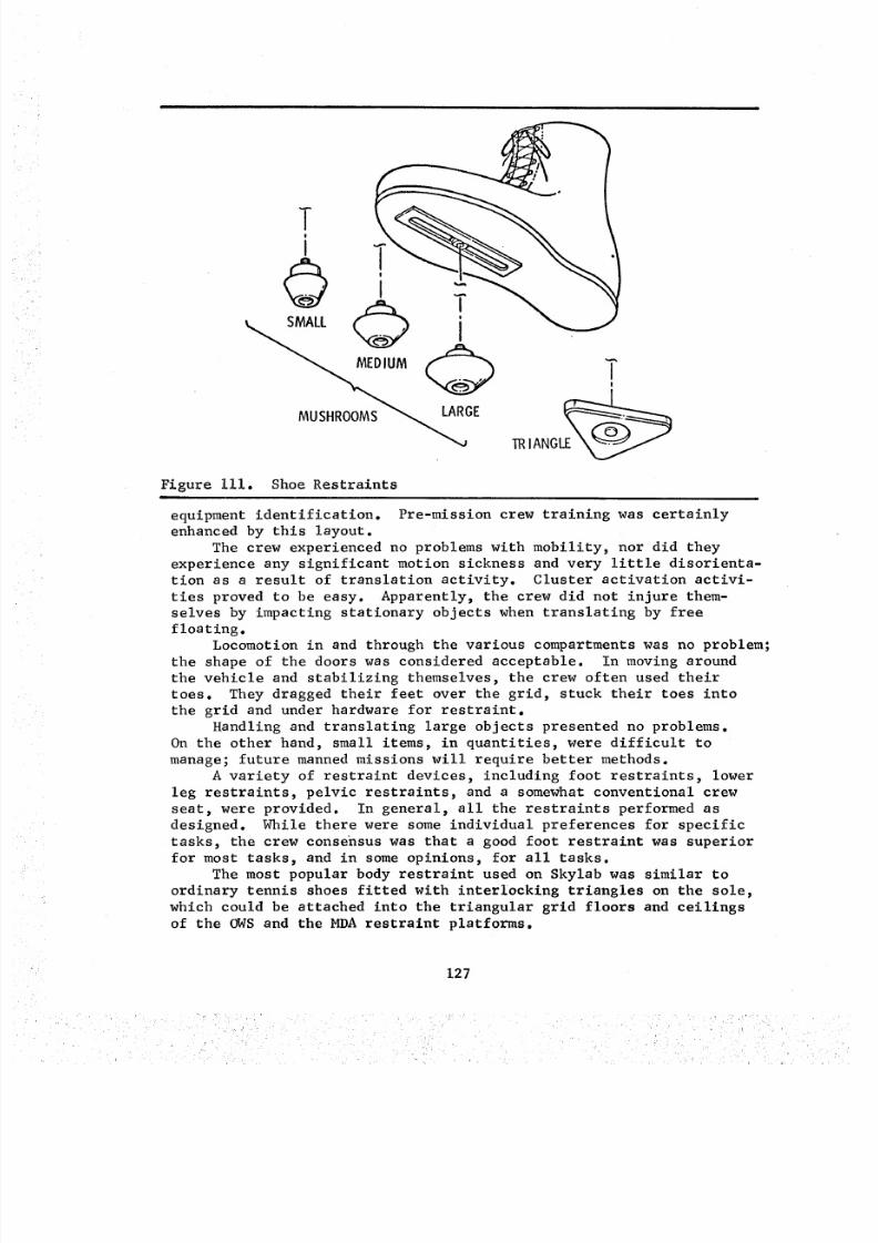
8/8/2019 MSFC Skylab Crew Systems Mission Evaluation
http://slidepdf.com/reader/full/msfc-skylab-crew-systems-mission-evaluation 151/397
TI
TRI ANGL_
Figure iii. Shoe Restraints
equipment identification. Pre-mission crew training was certainly
enhanced by this layout.
The crew experienced no problems with mobility, nor did they
experience any significant motion sickness and very little disorienta-
tion as a result of translation activity. Cluster activation activi-
ties proved to be easy. Apparently, the crew did not injure them-
selves by impacting stationary objects when translating by freefloating.
Locomotion in and through the various compartments was no problem;
the shape of the doors was considered acceptable. In moving around
the vehicle and stabilizing themselves, the crew often used their
toes. They dragged their feet over the grid, stuck their toes into
the grid and under hardware for restraint.
Handling and translating large objects presented no problems.
On the other hand, small items, in quantities, were difficult to
manage; future manned missions will require better methods.
A variety of restraint devices, including foot restraints, lower
leg restraints, pelvic restraints, and s somewhat conventional crew
seat, were provided. In general, all the restraints performed as
designed. While there were some individual preferences for specific
tasks, the crew consensus was that a good foot restraint was superior
for most tasks, and in some opinions, for all tasks.
The most popular body restraint used on Skylab was similar to
ordinary tennis shoes fitted with interlocking triangles on the sole,
which could be attached into the triangular grid floors and ceilings
of the OWS and the MDA restraint platforms.
127
8/8/2019 MSFC Skylab Crew Systems Mission Evaluation
http://slidepdf.com/reader/full/msfc-skylab-crew-systems-mission-evaluation 152/397
In future spacecraft design, particular attention should be
given to specific locations along a translation paths where directional
changes or tunnel entry will be required. A buffer of soft material
should be provided to protect the lower body extremities.
Some problems and design considerations for handling and translat-
ing large cargo or experiment items defined by the crew are as follows:• The food box was a reasonable size container (approximately
20" X 22" X 30"/200 pounds) to translate and not considered
too large for one man to maneuver in zero-g.
• Large items should be easily grasped to allow guidance duringtranslation.
• Long and thin items are easy to handle if one can see the
end of the item being maneuvered.
• Very large or heavy items can be maneuvered if the crewman
is adequately restrained.
A detailed description of crew usage and assessment of specific
mobility/stability items follows.
a. Fixed Aids
(i) Fixed Handrails and Handholds - Crew members
assessed the handrails as adequate. There appeared to be an adequate
quantity of fixed handrails, but many of them were in low use areas,such as the OWS forward dome. It is now obvious that hand-over-hand
translation inside a large space station, such as the OWS, is not
required as a means of locomotion. Fixed handrails were used primarily
as a "spring board" for body movement or as a "brake" or "clutch" for
re-orientation. The crew felt that many of the handrails located atwork stations should have been foot restraints.
The arms were the major means for the crewmen to propel themselves
in zero-g. This afforded great significance to the placement of
handholds and handrails throughout the vehicle. The SL-3 and SL-4
crews made numerous comments regarding the need for a greater number
of fixed aids to be deployed throughout the vehicle. Comments also
indicated that high traffic areas are prime candidates for additional
aids. The aids should protrude above equipment for easier accessibil-
ity. Another suggestion made was to locate handrails at hatch open-
ings and if possible, place them just inside the tunnel of the hatch
opening. The concensus of all crewmen was a need for more handholdsand handrails. These aids should be located as close as possible to
equipment thereby keeping "torque forces" and "opposite forces" as
close together as possible.
(2) WMC Foot Restraints - The two locations of the
foot restraints in the WMC were judged to be unsatisfactory. They
were assessed as not satisfactory when used in the non-nominal mode
(with the triangle shoes). The velcro did not hold well, and it
was too stiff and too short. A new concept for WMC foot restraint
straps was developed by JSC and was flown on the second mission.
This newly supplied strap did not perform as expected and was
also assessed as inadequate. Both the second and third crew assessed
128
8/8/2019 MSFC Skylab Crew Systems Mission Evaluation
http://slidepdf.com/reader/full/msfc-skylab-crew-systems-mission-evaluation 153/397
these devices similarly. The strap was too short to be used with
triangle shoes; the strap was too long for use without triangle shoes;
and it kept getting caught in the urine drawers.
(3) Fireman's Pole - The crews found this item to be
useful and, at times, preferred it over the flexible strap. Due to
the pole rigidity, they could grab it and change direction easily and
more accurately than with the flexible strap. The only objections werethat: a) it was possible to cut one's hands on the attachment roll
pins_ and b) the pole tended to rattle loudly when impacted, disturbing
crewmen attempting to sleep.
(4) Food Table Restraints - The table thigh restraints
were considered satisfactory and were usually used either as intended,
by design, with the thighs between the cross bars, or with the knees
over the innermost of the two cross bars, which was an improvised
method for using the restraint. All three crews were able to adjust
the thigh restraint tightly enough and at angles pleasing to eachindividual crewman.
Some crewmen used the foot restraint with the triangle shoes,
some used the restraint straps, and some did not use the foot restraint
at all. The light-duty foot restraints were seldom used because they
were not compatible with the triangle shoes, and were assessed as
inadequate because they came out of their slots and were difficult to
reinstall. This also applied to the revised straps launched on thesecond mission.
The use of the triangle shoes at the food table was the most
preferred method, with the cutouts for the triangle shoes used mostof the time. The third crew removed the foot restraints and used the
floor grid for the triangle shoes with the thigh restraints. This
provided more attach points for the triangle shoes and was used forthe remainder of the mission.
(5) Water Tank Foot Restraint Platform - The crewman
used this restraint in various ways. One crewman engaged one foot
in the triangular cutouts; others engaged both feet or stabilized
with the hands only. While installing water hoses and the condensate
tank hoses_ one crewman laid parallel to the platform and grasped itbetween his knees to allow freedom of both hands. All three crews
assessed the water tank foot restraint as very good and necessary for
most tasks performed in that area, particularly while working in the
ring lockers.
(6) Lower Leg Restraints - These restraints were used,
as intended, while attaching the condensate holding tank to its on-
orbit location. No other usage of this device was reported during the
second or third mission. Crew assessment indicated that they workedwell.
129
8/8/2019 MSFC Skylab Crew Systems Mission Evaluation
http://slidepdf.com/reader/full/msfc-skylab-crew-systems-mission-evaluation 154/397
(7) Grid - The floor and ceiling grid was used by all
three crews, as anticipated, for mobility and restraint. All crews
commented favorably on the usefulness of the grid. The two most
common complaints were: (i) the lack of more grid and, (2) the
blockage of the grid by either the installed equipment or the support-
ing structure. Besides its use in conjunction with the portable res-
traints, the grid itself was continually used as a handhold or foot-
hold. The WMC restraint evaluation always referred to the lack of
grid. The second crew suggested, during the debriefing, that grid
should have been provided in the WMC.
One minor deficiency associated with the grid was the problem
of particle migration, such as food crumbs and spills. The grid was
difficult to clean because of the small holes, sharp corners, etc.
(8) Fecal Collector Restraints - Fecal collector
restraints were assessed by the three crews in somewhat differentmethods.
In general, they felt the restraints allowed them to satisfactor-ily accomplish fecal collection. They all agreed that both the hand-holds and foot restraints must be used. Some felt that the belt was
an absolute necessity, while others stated that it was not required.
They all commented, however, that in one way or another the equipment
served its intended purpose.
The major complaint about the WMC was the lack of adequate
restraints for the performance of the various management tasks assoc-
iated with waste management and M071/M073 experiments, such as urine
and fecal bag changeout_ sampling, cutting, crimping, etc.
(9) Shower Foot Restraint - The shower foot restraint
was assessed as effective for its intended use; however, it should
have been padded for barefoot use. Because of its simplicity, this
restraint concept could be considered for application in other areas.
(i0) ATM Foot Restraint Platform - The use of the
triangle foot restraint, contrasted to the Skylab Restraint Assembly
(ATM Seat/Backrest), seemed to be the better operation stability
aid. The SL-3 and SL-4 crews did not report or express any fatigue
due to remaining upright at the ATM C&D. The crewmen considered this
foot restraint very adequate in performing all tasks at the ATM C&D
panel. The SL-2 crew did prefer the Skylab Restraint Assembly; however
the foot restraint was also deemed acceptable for ATM operations. The
ATM foot restraint, used throughout the mission in the lowest position,
permitted the crewman an operational envelope completely adequate toperform all ATM operational tasks. It was suggested that the lowest
position (position 3, Figure 108) could have been even lower.
(II) Skylab Restraint Assembly - The SL-2 crew used the
ATM Seat/Backrest Restraint continuously, thought it was very useful
and prevented them from becoming very tired while operating the ATM
C&D Panel. The SL-3 and SL-4 crews thought that this restraint merely
130
8/8/2019 MSFC Skylab Crew Systems Mission Evaluation
http://slidepdf.com/reader/full/msfc-skylab-crew-systems-mission-evaluation 155/397
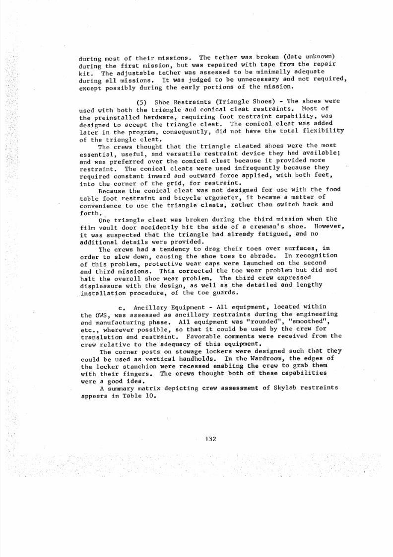
8/8/2019 MSFC Skylab Crew Systems Mission Evaluation
http://slidepdf.com/reader/full/msfc-skylab-crew-systems-mission-evaluation 156/397
during most of their missions. The tether was broken (date unknown)
during the first mission, but was repaired with tape from the repair
kit. The adjustable tether was assessed to be minimally adequate
during all missions. It was judged to be unnecessary and not required,
except possibly during the early portions of the mission.
(5) Shoe Restraints (Triangle Shoes) - The shoes were
used with both the triangle and conical cleat restraints. Most of
the preinstalled hardware, requiring foot restraint capability, was
designed to accept the triangle cleat. The conical cleat was added
later in the program, consequently, did not have the total flexibility
of the triangle cleat.
The crews thought that the triangle cleated shoes were the most
essential, useful, and versatile restraint device they had available;
and was preferred over the conical cleat because it provided more
restraint. The conical cleats were used infrequently because they
required constant inward and outward force applied, with both feet,
into the corner of the grid, for restraint.Because the conical cleat was not designed for use with the food
table foot restraint and bicycle ergometer, it became a matter of
convenience to use the triangle cleats, rather than switch back and
forth.
One triangle cleat was broken during the third mission when thefilm vault door accidently hit the side of a crewman's shoe. However,
it was suspected that the triangle had already fatigued, and no
additional details were provided.
The crews had a tendency to drag their toes over surfaces, in
order to slow down, causing the shoe toes to abrade. In recognition
of this problem, protective wear caps were launched on the secondand third missions. This corrected the toe wear problem but did not
halt the overall shoe wear problem. The third crew expressed
displeasure with the design, as well as the detailed and lengthy
installation procedure, of the toe guards.
c. Ancillary Equipment - All equipment, located within
the OWS, was assessed as ancillary restraints during the engineering
and manufacturing phase. All equipment was "rounded", "smoothed",
etc., wherever possible, so that it could be used by the crew fortranslation and restraint. Favorable comments were received from the
crew relative to the adequacy of this equipment.
The corner posts on stowage lockers were designed such that they
could be used as vertical handholds. In the Wardroom, the edges of
the locker stanchion were recessed enabling the crew to grab themwith their fingers. The crews thought both of these capabilities
were a good idea.
A sun_nary matrix depicting crew assessment of Skylab restraints
appears in Table I0.
132
8/8/2019 MSFC Skylab Crew Systems Mission Evaluation
http://slidepdf.com/reader/full/msfc-skylab-crew-systems-mission-evaluation 157/397
,
PER FORMANCE
>_c_O
Hoc_
F-4
FIXED RESTRAINTS
Fixed Handrails & Handholds
WMC Foot Restraints
Fireman's Pole
Food Table Thigh Restraints
H20 Tank Foot Restraint Platform
OWS Lower Leg Restraints
Floor and Ceiling Grid
X
X
X
X
X
Fecal Collector Restraints X
ATM Foot Restraint Platform X
Skylab Restraint Assembly X
M_512/EREP Foot Restraint X
Shower Foot Restraint X
X
PORTABLE AIDS
PGA Foot Restraints
Portable Handholds
Portable Tether Brackets
Adjustable Thethers
Triangle Shoes
X
X
X
o_F.r..1
X
X
Table i0. Crew Assessment of_Skylab Restraintsi T
133
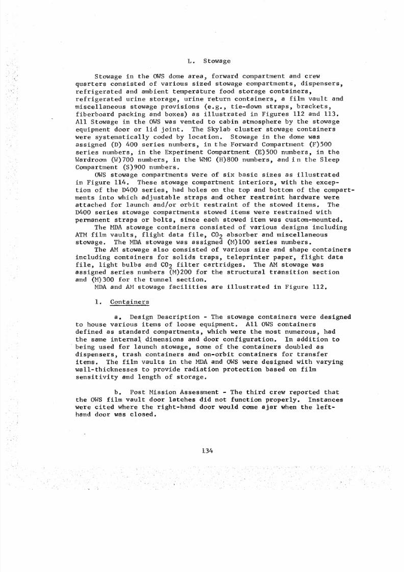
8/8/2019 MSFC Skylab Crew Systems Mission Evaluation
http://slidepdf.com/reader/full/msfc-skylab-crew-systems-mission-evaluation 158/397
L. Stowage
Stowagein the OWSdome area, forward compartment and crew
quarters consisted of various sized stowage compartments, dispensers,
refrigerated and ambient temperature food storage containers,refrigerated urine storage, urine return containers, a film vault and
miscellaneous stowage provisions (e.g., tie-down straps, brackets,
fiberboard packing and boxes) as illustrated in Figures 112 and 113.
All Stowage in the OWS was vented to cabin atmosphere by the stowage
equipment door or lid joint. The Skylab cluster stowage containers
were systematically coded by location. Stowage in the dome was
assigned (D) 400 series numbers, in the Forward Compartment (F)500
series numbers, in the Experiment Compartment (E)500 numbers, in the
Wardroom (W)700 numbers, in the WMC (H)800 numbers, and in the Sleep
Compartment (S)900 numbers.
OWS stowage compartments were of six basic sizes as illustrated
in Figure 114. These stowage compartment interiors, with the excep-
tion of the D400 series, had holes on the top and bottom of the compart-
ments into which adjustable straps and other restraint hardware wereattached for launch and/or orbit restraint of the stowed items. The
D400 series stowage compartments stowed items were restrained with
permanent straps or bolts, since each stowed item was custom-mounted.
The MDA stowage containers consisted of various designs including
ATM film vaults, flight data file, C02 absorber and miscellaneousstowage. The MDA stowage was assigned (M)I00 series numbers.
The AM stowage also consisted of various size and shape containers
including containers for solids traps, teleprinter paper, flight data
file, light bulbs and C02 filter cartridges. The AM stowage was
assigned series numbers (M)200 for the structural transition sectionand (M)300 for the tunnel section.
MDA and AM stowage facilities are illustrated in Figure 112.
i. Containers
a. Design Description - The stowage containers were designed
to house various items of loose equipment. All OWS containers
defined as standard compartments, which were the most numerous, had
the same internal dimensions and door configuration. In addition to
being used for launch stowage, some of the containers doubled as
dispensers, trash containers and on-orbit containers for transfer
items. The film vaults in the MDA and OWS were designed with varying
wall-thicknesses to provide radiation protection based on film
sensitivity and length of storage.
b. Post Mission Assessment - The third crew reported that
the OWS film vault door latches did not function properly. Instances
were cited where the right-hand door would come ajar when the left-
hand door was closed.
134
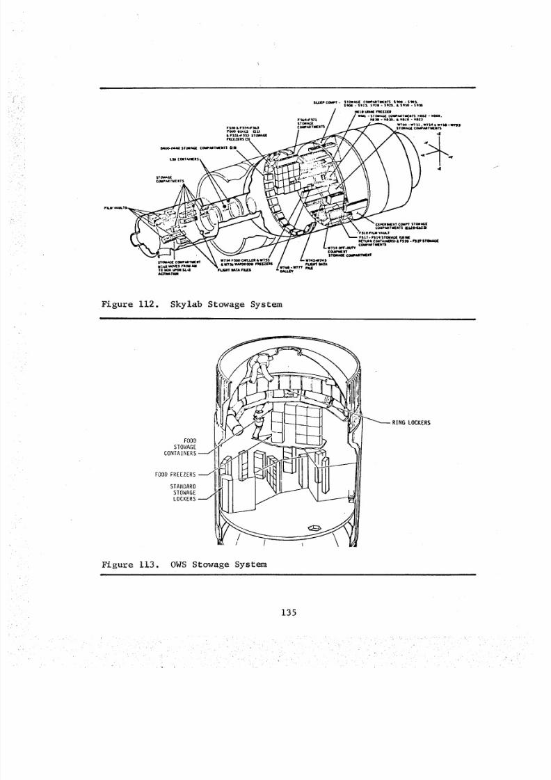
8/8/2019 MSFC Skylab Crew Systems Mission Evaluation
http://slidepdf.com/reader/full/msfc-skylab-crew-systems-mission-evaluation 159/397
r s_4 & F$_4-Fg4_FO(_ SCx[$ QU
0 4_ ¢_ 44 4 S TO aA G£ C OW 'M TU (_ T1 aJ
MT m W?I_F_R&WTS$ST_ Cf_ll _ W FIt_
TO _ t a* O_ S _. 4 FLa;UT IIAT*_/_TWAT_II
Figure 112. Skylab Stowage System
FOODSTOWAGE
CONTAINERS
FOOD FREEZERS
STANDARDSTOWAGELOCKERS
LOCKERS
Figure 113. OWS Stowage System
135
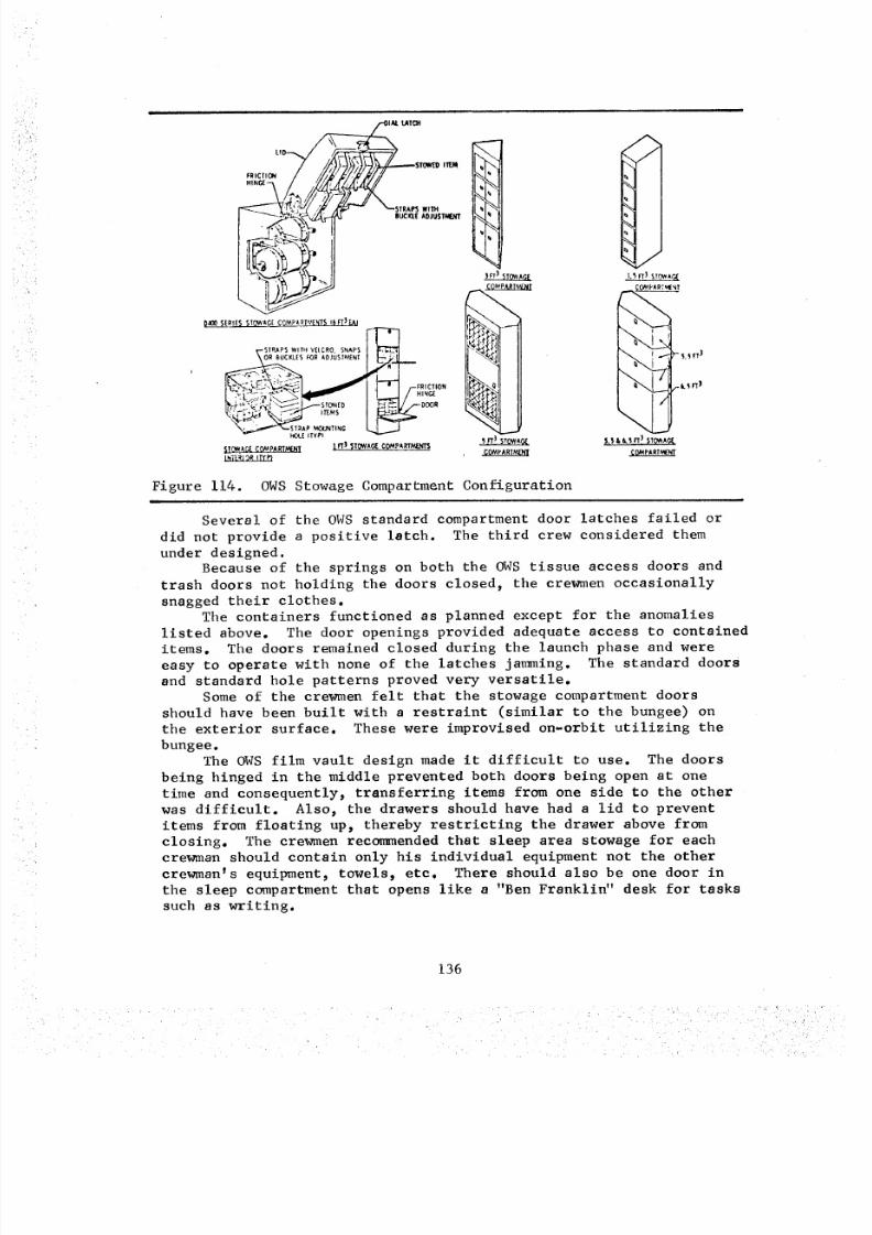
8/8/2019 MSFC Skylab Crew Systems Mission Evaluation
http://slidepdf.com/reader/full/msfc-skylab-crew-systems-mission-evaluation 160/397
•:
D_O0 _ERIE$ STQ_AGE C_PART*,!E_T$ 16FT3 _._1
r-T-,,_-'STPdIPS WITH V[tCRO. SNAPS t _"
_.,,_ _ COMpA RTh'_rJCf
m
F-FRICTION
HINGIE
-- DOOR
FT3 _ITQWA_ C(_PA,_Tt,_NTS
I
Figure 114. OWS Stowage Compartment Configuration
/
,.is rr_ STOAt(
PA_T_T
_'_FT 1
\_._n _ _
Several of the OWS standard compartment door latches failed or
did not provide a positive latch. The third crew considered them
under designed.Because of the springs on both the OWS tissue access doors and
trash doors not holding the doors closed, the crewmen occasionally
snagged their clothes.The containers functioned as planned except for the anomalies
listed above. The door openings provided adequate access to containeditems. The doors remained closed during the launch phase and were
easy to operate with none of the latches jamming. The standard doors
and standard hole patterns proved very versatile.
Some of the crewmen felt that the stowage compartment doors
should have been built with a restraint (similar to the bungee) on
the exterior surface. These were improvised on-orbit utilizing the
bungee.The OWS film vault design made it difficult to use. The doors
being hinged in the middle prevented both doors being open at one
time and consequently_ transferring items from one side to the other
was difficult. Also, the drawers should have had a lid to preventitems from floating up, thereby restricting the drawer above from
closing. The crewmen recommended that sleep area stowage for each
crewman should contain only his individual equipment not the other
crewman's equipment, towels_ etc. There should also be one door in
the sleep compartment that opens like a "Ben Franklin" desk for tasks
such as writing.
136
8/8/2019 MSFC Skylab Crew Systems Mission Evaluation
http://slidepdf.com/reader/full/msfc-skylab-crew-systems-mission-evaluation 161/397
2. Internal Arrangement
a. Design Description - The internal arrangement was designed
to provide equipment stowage in use areas and in some instances to
group like items together; that is, spares, dispenser resupply items,
photographic equipment, etc.
b. Post Mission Assessment - In most instances, the hard-
ware arrangement proved satisfactory, was utilized as designed, with
no anomalies reported.
Trash generation areas should be closely evaluated during
training to identify optimum placement of containers in the flight
vehicle. This point was well illustrated when the first crew exchanged
some container doors to provide each crewman a trash compartment inthe wardroom. This demonstrated the versatility of the standard
compartment doors. These changes were accomplished by pulling the
hinge pins, exchanging the doors, and reinstalling the hinge pins.Comments from the crews indicated that some changes to the
stowage system are recommended. For example, tools should be stowed
together and identified by tool type rather than by tool use. They
recommended that the trash bags should be stowed in one, central
location. Also, items stowed in drawers should be identified by labels
placed on the exterior of the drawer to indicate the drawer's contents.
Finally, they recommended that increased stowage volume should have
been provided in the Experiment and Waste Management Compartments.
3. Equipment Restraints
a. Design Description - Equipment restraints fall into two
general categories: launch restraints and on-orbit restraints.
Launch restraints were designed to protect equipment during poweredflight and allow removal of equipment for usage on-orbit. On-orbit
restraints were designed to restrain equipment at various temporary
locations during the mission. This included short straps, long straps,
equipment restraints, universal mount, and bungees, etc. The short
strap was 12-inches long with snaps 4-inches on center. The long
strap was 26-inches long and could be adjusted from approximately
22-inches to 8-inches. Velcro was provided on the long strap for
adjustment. Bungees were fabricated from coiled springs with attach
snaps and hooks on each end. They were approximately ll-inches long
and stretched to approximately 16-inches. There was also a supply
of "stick-on" snaps and Velcro in the repair kit for use at the
crew's option.
b. Post Mission Assessment - The launch restraints were
used as planned. On-orbit restraints were used extensively. The
short straps should have been a couple of inches longer to make themmore useful.
137
8/8/2019 MSFC Skylab Crew Systems Mission Evaluation
http://slidepdf.com/reader/full/msfc-skylab-crew-systems-mission-evaluation 162/397
The First Mission crew reported the 400-foot film cassette res-traints in OWSilm vault drawer B kept moving to the rear of drawer.The restraining tab was_pparently not locking the film cassette inplace in the drawer. These restraints existed in other film vaultdrawers and worked satisfactorily.
The second crew found camera equipment loose in one of the OWSfilm vault drawers. The stowage requirements had not been anticipatedprior to SL-I launch and therefore restraints had not been provided.
In someinstances, mosite restraints allowed small items tofloat free. The pudding can restraints in the food galley allowed thecans to float out. This restraint was categorized as inadequate.
There were no anomalies reported for MDAor AMstowage hardware.Nomalfunction of stowed_uipment was reported as a direct result
of the launch environment. All stowage containers, stowage positions,and restraints were used as anticipated.
The crew recommendedmore temporary stowage facilities throughoutthe vehicle. The straps, used extensively in the OWS,were somewhat
difficult to use because they were stiff and rough, and in somecases,inside stowage containers, the buckles woundup in hard-to-reach placeswhen the locker was partially empty.
The crewmencormnentedhat there should have been more on-orbitstowage facilities near use locations. An example is a more permanentstowage capability for photographic equipment near the Wardroomwindow.
Oneconcept of stowage that the crews disliked was bags in bagsand a little cubical for numerous individual items (e.g., the flash-light stowage). One point to be made is that launch padding is notneeded for on-orbit stowage.
4. Fasteners
a. Design Description - A variety of different crewoperated fasteners were used on the Skylab vehicle. Reasons forthese differences include:
(I) The participation of several contractors, and
attendant high costs which would have been incurred by strict require-
ment for design commonality.
(2) An effort by all participating designers to select
the appropriate fastener for each application.
The lack of design cormnonality was a positive, though unanticipated_
bonus in that it permitted a comparative evaluation of several typesof fasteners which may be candidates for future spacecraft application.
The results of the ranking of nineteen fasteners by the Skylab 2 and
3 crewmen was obtained. Table ii briefing describes each fastener
and provides the average rating (based on a i-i0 scale)_ the rankorder, and a synopsis of comments for each.
138
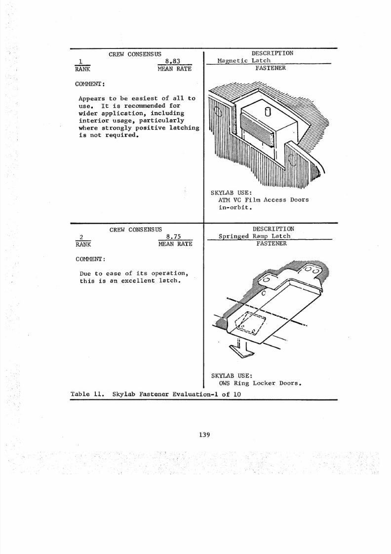
8/8/2019 MSFC Skylab Crew Systems Mission Evaluation
http://slidepdf.com/reader/full/msfc-skylab-crew-systems-mission-evaluation 163/397
RANK
COMMENT
CREWCONSENSUS8.83
MEANRATE
Appears to be easiest of all touse. It is recommended for
wider application, including
interior usage, particularly
where strongly positive latching
is not required.
CREW CONSENSUS
2 8.75
RANK MEAN RATE
COMMENT :
Due to ease of its operation,this is an excellent latch.
Table ii.
DESCRIPTION
Masnetic LatchFASTENER
SKYLAB USE :
ATM VC Film Access Doors
in-orbit.
DESCRIPTION
Sprinted Rgm P LatchFASTENER
SKYLAB USE:
OWS Ring Locker Doors.
Skylab Fastener Evaluation-I of i0
139
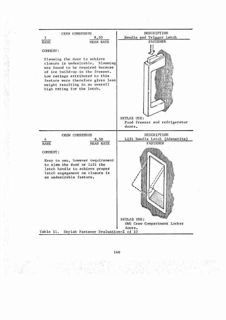
8/8/2019 MSFC Skylab Crew Systems Mission Evaluation
http://slidepdf.com/reader/full/msfc-skylab-crew-systems-mission-evaluation 164/397
CREW CONSENSUS
3 8.50
RANK MEAN RATE
COMMENT :
Slamming the door to achieve
closure is undesirable. Slamming
was found to be required because
of ice build-up in the freezer.
Low ratings attributed to this
feature were therefore given less
weight resulting in an overall
high rating for the latch.
DESCRIPTION
Handle and Trigser LatchFASTENER
CREW CONSENSUS
4 8.50
RA_ MEAN RATE
COMMENT:
Easy to use, however requirementto slam the door or lift the
latch handle to achieve proper
latch engagement on closure isan undesirable feature.
Table ii.
\SKYLAB USE :
Food freezer and refrigeratordoors.
DESCRIPTION
Lift Handle Latch (Adamsrite)
!1
I
FASTENER
SKYLAB USE:
OWS Crew Compartment Lockerdoors.
Skylab Fastener Evaluation-2 of i0
140
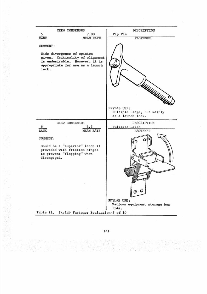
8/8/2019 MSFC Skylab Crew Systems Mission Evaluation
http://slidepdf.com/reader/full/msfc-skylab-crew-systems-mission-evaluation 165/397
CREWCONSENSUS5 7.00
RANK MEANRATE
COMMENT
Wide divergence of opinion
given. Criticality of alignment
is undesirable. However, it is
appropriate for use as a launchlock.
CREW CONSENSUS
6 6.6
RANK MEAN RATE
COMMENT :
Could be a "superior" latch if
provided with friction hinges
to prevent "flopping" when
disengaged.
DESCRIPTION
,Pip Pip, ,,FASTENER
Table ii.i
SKYLAB USE:
Multiple usage, but mainly
as a launch lock.
DESCRIPTION
Suitcase Latch
FASTENER
SKYLAB USE:
Various equipment storage boxlids.
Skylab Fastener Evaluation-3 of i0
141
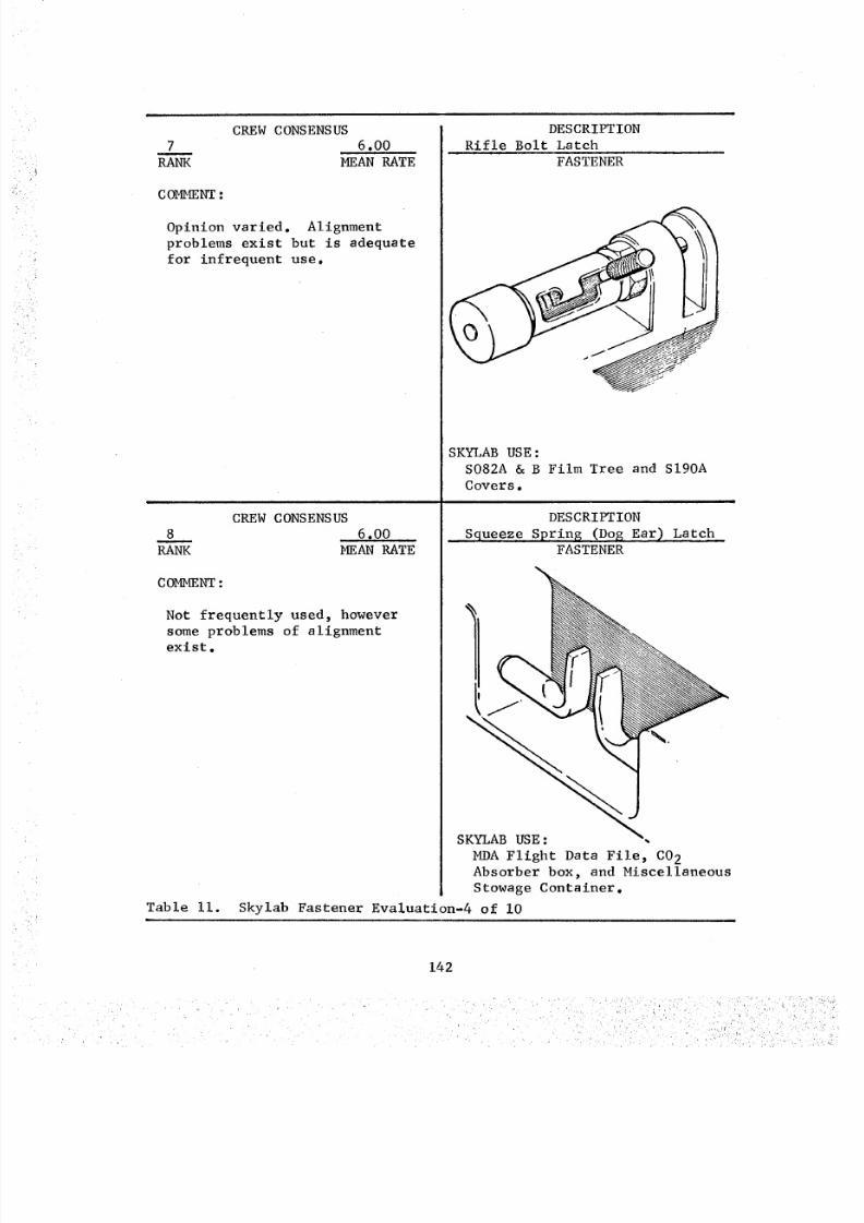
8/8/2019 MSFC Skylab Crew Systems Mission Evaluation
http://slidepdf.com/reader/full/msfc-skylab-crew-systems-mission-evaluation 166/397
7m
RANK
COMMENT :
Opinion varied.
CREW CONSENSUS6.00
MEAN RATE
Alignment
problems exist but is adequate
for infrequent use.
CREW CONSENSUS
8 6.00RANK MEAN RATE
COMMENT :
Not frequently used, however
some problems of alignment
exist.
Table ii.
DESCRIPTION
Rifle Bolt Latch
FASTENER
SKYLAB USE:
S082A & B Film Tree and SI90A
Covers.m
DESCRIPTION
•Squeeze Spring (Dog Ear) L•atchFASTENER
SKYLAB USE:
MDA Flight Data File, C02Absorber box, and Miscellaneous
Stowage Container.
Skylab Fastener Evaluation-4 of i0
142
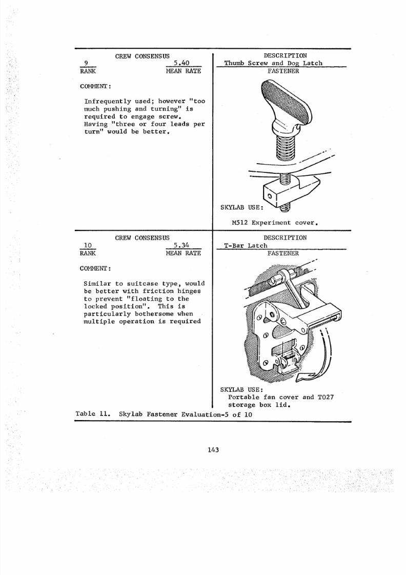
8/8/2019 MSFC Skylab Crew Systems Mission Evaluation
http://slidepdf.com/reader/full/msfc-skylab-crew-systems-mission-evaluation 167/397
9RANK
COMMENT :
CREW CONSENSUS5.40
MEAN RATE
Infrequently used; however "too
much pushing and turning" is
required to engage screw.
Having "three or four leads perturn" would be better.
CREW CONSENSUS
I0 5.34
RANK MEAN RATE
COMMENT :
DESCRIPTION
Thumb Screw and Do S LatchFASTENER
SKYLAB USE :
M512 Experiment cover.
Table ii.|
DESCRIPTION
T-Bar Latch
Similar to suitcase type, wouldbe better with friction hinges
to prevent "floating to the
locked position". This is
particularly bothersome when
multiple operation is required
FASTENER
i°,
SKYLAB USE:
Portable fan cover and T027
storage box lid.
Skylab Fastener Evaluation-5 of i0
143
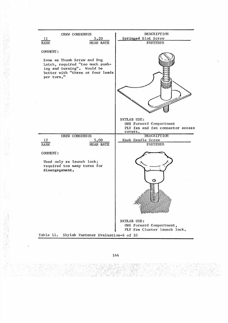
8/8/2019 MSFC Skylab Crew Systems Mission Evaluation
http://slidepdf.com/reader/full/msfc-skylab-crew-systems-mission-evaluation 168/397
CREWCONSENSUSii 5.20
RANK MEANRATE
COMMENTSameas ThumbScrew and DogLatch, required "too muchpush-ing and turning". Would bebetter with "three or four leadsper turn."
CREWCONSENSUS12 5.00
RANK MEANRATE
COMMENT
Table ii.
Used only as launch lock;required too manyturns fordisengagement.
DESCRIPTION_Springed Slot Screw
FASTENER
SKYLABUSE:OWSForward CompartmentPLVfan and fan connector accesscovers.
DESCRIPTIONKnobHandle Screw
FASTENER
SKYLABUSE:OWSForward Compartment,PLVFan Cluster launch lock.
Skylab Fastener Evaluation-6 of i0
144
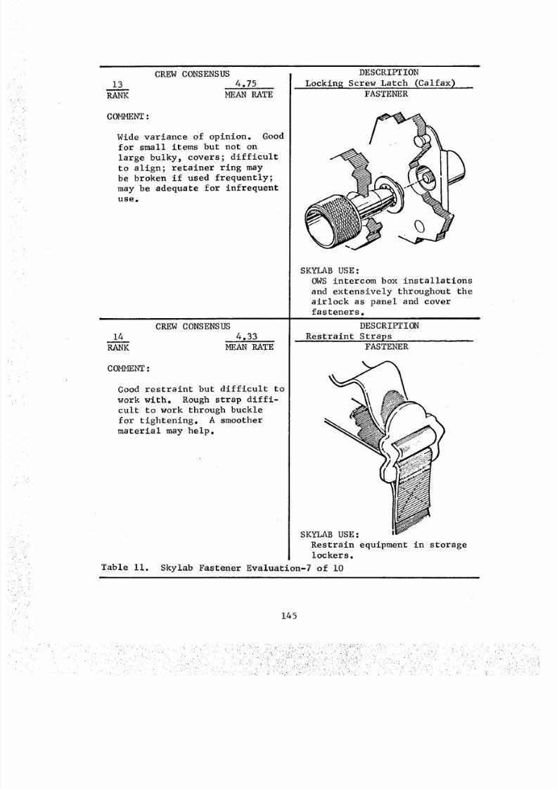
8/8/2019 MSFC Skylab Crew Systems Mission Evaluation
http://slidepdf.com/reader/full/msfc-skylab-crew-systems-mission-evaluation 169/397
CREWCONSENSUS13 4.75
RANK MEANRATE
COMMENT
Wide variance of opinion. Goodfor small items but not onlarge bulky, covers; difficultto align; retainer ring maybe broken if used frequently;may be adequate for infrequentuse.
CREW CONSENSUS
14m
RANK
COMMENT :
4.33
MEAN RATE
DESCRIPTION
Locking Screw Latch (Calfax)FASTENER
Good restraint but difficult towork with. Rough strap diffi-
cult to work through buckle
for tightening. A smoother
>
SKYLAB USE:
OWS intercom box installations
and extensively throughout the
airlock as panel and coverfasteners.
DESCRIPTION
Restraint Straps
material may help.
Table ii.
FASTENER
SKYLAB USE:
Restrain equipment in storagelockers.
Skylab Fastener Evaluation-7 of i0
145
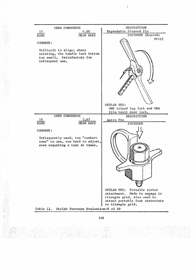
8/8/2019 MSFC Skylab Crew Systems Mission Evaluation
http://slidepdf.com/reader/full/msfc-skylab-crew-systems-mission-evaluation 170/397
15
RANK
CREW CONSENSUS
4.00
COMMENT :
MEAN RATE
Difficult to align; where
existing, the handle lock button
too small. Satisfactory for
infrequent use.
CREW CONSENSUS
16 3.67
RANK MEAN RATE
COMMENT :
Infrequently used, too "cumber-some" to use_ too hard to adjust_
even requiring a tool at times.
Table ii.
i
DEscRIPTION
..... xpandable Sleeved PinFASTENER (Exp_ndo
Grip)
SKYLAB USE:
OWS tripod leg lock and MDAfilm vault door lock.
DESCRIPTION
Astro Pin
FASTENER
f --
SKYI_B USE: Portable tether
attachment. Made to engage in
triangle grid, also used to
attach portable foot restraints
to triangle grid.
Skylab Fastener Evaluation-8 of I0
146
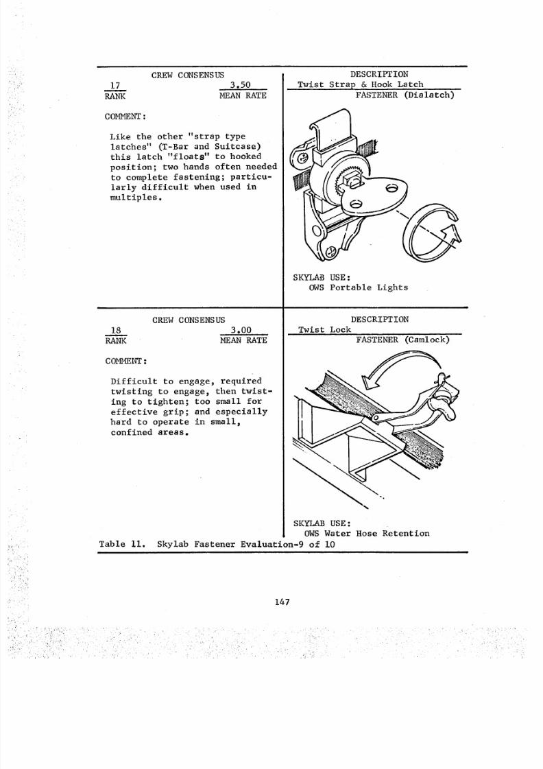
8/8/2019 MSFC Skylab Crew Systems Mission Evaluation
http://slidepdf.com/reader/full/msfc-skylab-crew-systems-mission-evaluation 171/397
CREW CONSENSUS
17 3.50
RA_ MEAN RATE
COMMENT :
Like the other "strap type
latches" (T-Bar and Suitcase)
this latch "floats" to hooked
position; two hands often needed
to complete fastening; particu-
larly difficult when used in
multiples.
CREW CONSENSUS
18 3.00
RANK MEAN RATE
COMMENT:
Difficult to engage, requiredtwisting to engage, then twist-
ing to tighten; too small foreffective grip; and especially
hard to operate in small_
confined areas.
Table ii.
DESCRIPTION
Twist Strap & Hook LatchFASTENER (Dialatch)
SKYLAB USE :
OWS Portable Lights
DESCRIPT ION
Twist Lock
FASTENER (Camlock)
SKYI_B USE :OWS Water Hose Retention
Skylab Fastener Evaluation-9 of i0
147
• j _
8/8/2019 MSFC Skylab Crew Systems Mission Evaluation
http://slidepdf.com/reader/full/msfc-skylab-crew-systems-mission-evaluation 172/397
CREW CONSENSUS
19 2.00
RANK MEAN RATE
COMMENT •
Not positive locking - comes
loose when bumped; sometimes
jams requiring tool to release;
tends to deteriorate with use.
Table Ii.
DESCRIPTION
Push Button Latch
FASTENER
\.!
SKYLAB USE :
Food Tray lid to trayfastener.
Sk_lab Fastener Evaluation-10 of i0
b. Post Mission Assessment - Most of the different types
of fasteners onboard were used extensively by one or more crewmenfrom each manned mission.
Some of the lift handle latches (used on OWS standard lockers)
were broken as previously mentioned.
Several of the locking screw latch (Calfax) captive retainerswere broken.
The push button latch (used on food tray lid) slipped all the
way through the latching hole in the mating surface several times
and required prying with pointed tools from underneath. Also, when
latched, it did not give a positive latch _nd was accidently
released when bumped.
In addition to the fasteners in Table II, two latches were
provided outside the vehicle on the film access doors of Apollo
Telescope Mount (ATM) for use during Extravehicular Activity (EVA).
The center work station (VC) access door latch, Figure 115, functioned
adequately but was criticized by the crewmen because its operation
(push-to-open 2 pull-to-close) was opposite of that normally expected.
It is noted, also, that a separate lock was required for launch.The Sun End Workstation door latching mechanism, Figure 116,
combined launch restraint and orbital operation in the same mechanism.
Its orbital operation as a door lock was excellent. It also served
as a handhold when in the locked position.
148
8/8/2019 MSFC Skylab Crew Systems Mission Evaluation
http://slidepdf.com/reader/full/msfc-skylab-crew-systems-mission-evaluation 173/397
Figure 115. ATMVC Film Access Door
Figure 116. ATM VS Film Access Door Lock
149
8/8/2019 MSFC Skylab Crew Systems Mission Evaluation
http://slidepdf.com/reader/full/msfc-skylab-crew-systems-mission-evaluation 174/397
8/8/2019 MSFC Skylab Crew Systems Mission Evaluation
http://slidepdf.com/reader/full/msfc-skylab-crew-systems-mission-evaluation 175/397
FASTENER MEAN STD
RATE DEV
I. Magnetic Latch 8.83 I. 07
2.Springed
RampLatch 8.75 1.07
3. Handle & Trigger
Latch 8.50 0.87
4. Lift Handle Latch 8.50 I. 12
5. Pip Pin 7.00 I. 83
6. Suitcase Latch 6.16 1.46
7. Rifle Bolt Latch 6.00 I. 63
8. Squeeze Spring
Latch 6.00 2.19
9. Thumb Screw &
Dog Latch 5.40 I. 62
I0. T-Bar Latch 5.34 I. 53
FASTENER
1 I. Springed Slot Screw
12. KnobHandle
Screw13. Locking Screw Latch
(Catfax) *
14. Restraint Straps
15. Expandable Sleeved Pin
Expando Grip
16. Astro Pin
17. Twist Strap and Hook"
Latch (Dialatch)18. Twist Lock (Camtock)
19. Push Button Latch*
MEAN _TDRATE ISEV
s. zo I. 33
5. O0 1.67
4.75 2.27
4.33 I. 79
4.00 I. 63
3.67 1.97
3.50 1.383.00 1.15
2.00 0.82
*Rating weighted in'accordance with frequency of use (see "Discussiont'above).
Table 12. Rank Order, Crew Subjective Evaluation of Skylab Fasteners
On Orbit Only*
I. Magnetic Latch
2. Handle & TriggerLatch
3. Squeeze Spring Latch
4. Push Button Latch
Launch and On-Orbit Use
,i
Frequently Engaged/
Disengaged in Flight=, ....
I. Springed Ramp
Latch
Z. Lift Handle Latch
3. Pip Pin4. Suitcase Latch
5. Locking Screw Latch(Calfax)
6. Restraint Straps"
7. Twist Strap and Hook
(Diatatch)
Infrequently Engaged/
Disengaged in Flight
I, Rifle Bolt Latch
g. Thumb Screw &
Dog Latch
3. T-bar Latch
4. 8pringed Slot Screw
_, Knob Handle Screw
6. Expandable Sleeved
• Pin (Expando Grip) •7. Astro Pin
8. Twist Lock (Camtock)
*Required Additional Provisions to Withstand Launch Evironment
Table 13. Use Category Ranking of Fasteners
151
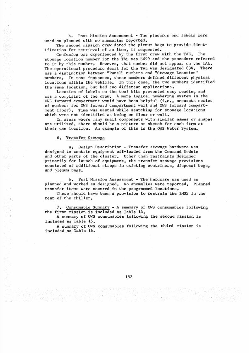
8/8/2019 MSFC Skylab Crew Systems Mission Evaluation
http://slidepdf.com/reader/full/msfc-skylab-crew-systems-mission-evaluation 176/397
b. Post Mission Assessment - The placards and labels were
used as planned with no anomalies reported.The second mission crew dated the plenum bags to provide ident-
ification for retrieval of an item, if requested.
Confusion was experienced by the first crew with the TAL'. The
stowage location nun_er for the TAL was E699 and the procedure referred
to it by this number. However, that number did not appear on the TAL.
The operational procedure decal for the TAL was designated 634. Therewas a distinction between "Panel" numbers and "Stowage Location"
numbers. In most instances, these numbers defined different physical
locations within the vehicle. In this case, the two numbers identified
the same location_ but had two different applications.Location of labels on the tool kits prevented easy reading and
was a complaint of the crew. A more logical numbering system in the
OWS forward compartment would have been helpful (i.e., separate series
of numbers for OWS forward compartment wall and OWS forward compart-
ment floor). Time was wasted while searching for stowage locations
which were not identified as being on floor or wall.
In areas where many small components with similar names or shapes
are utilized, there should be a picture or sketch for each item attheir use location. An example of this is the OWS Water System.
6. Transfer Stowage
a. Design Description - Transfer stowage hardware was
designed to contain equipment off-loaded from the Command Module
and other parts of the cluster. Other than restraints designed
primarily for launch of equipment, the transfer stowage provisions
consisted of additional straps in existing containers, disposal bags_and plenum bags.
b. Post Mission Assessment - The hardware was used as
planned and worked as designed. No anomalies were reported. Planned
transfer items were secured in the programmed locations.
There should have been a provision to restrain the IMSS in the
rear of the chiller.
7. Consumable Summary - A summary of OWS consumables followingthe first mission is included as Table 14.
A summary of OWS consumables following the second mission isincluded as Table 15.
A summary of OWS consumables following the third mission isincluded as Table 16.
152
8/8/2019 MSFC Skylab Crew Systems Mission Evaluation
http://slidepdf.com/reader/full/msfc-skylab-crew-systems-mission-evaluation 177/397
k
Trash Bags
Dtsposal Bags
UrineOlsposal Bags
Utillty Wipes
GPTissues
Bloclde Wipes
Wet Wipes
*Plenum Bags
UrineCollection Bags
Fe cal Bags
Vacuum CleanerBags
On-Board atSL-I Launch
366
168
149
23 Boxes@ 196 = 4508
11 Boxes@ 392 • 4312
5 Boxes@ 70 = 350
7 Boxes
28
432
465
140
On-Board atEnd of First
Mission
344
120
109
21 .5 Boxe s
QuantityUsed - First
Mission
22
48
40
1.5 Boxes
QuantityExpected UsageFirst Mission
73
33
28
4.6 Boxes
g Boxe s
4.6 Boxes
6.4 Boxes
22
360
417
135
2 Boxes
0.4 Boxes
0.6 Boxes
6
75
48
5
2.2 Boxes
1 Box
1.4 Boxes
3/Day 84
84
24
Remarks
3 Urine Bagscarried on SL-2 CM
* 6 Plenum Bags are in the Plenum Ares (5 full and 1-3/4 full).
Table 14. Consumable Sun_ary - First Mission - i of 2
8/8/2019 MSFC Skylab Crew Systems Mission Evaluation
http://slidepdf.com/reader/full/msfc-skylab-crew-systems-mission-evaluation 178/397
U_neSample Bags
112 UrineSample Bags
ContingencyFecal Bags
Washcloths
Towels
On-Board atSL-1 Launch
On-Board atEnd of First
Mission
375
125
185
840
420
312
104
184
747
385
Quantity UsedFirst Mission
63
21
93
35
Quantity ExpectedUsage
First Mission
66
18
A/R
168
84
Remarks
Table 14. Consumable Summary - First Mission - 2 of 2i
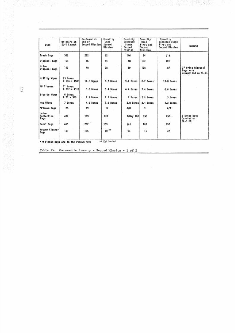
8/8/2019 MSFC Skylab Crew Systems Mission Evaluation
http://slidepdf.com/reader/full/msfc-skylab-crew-systems-mission-evaluation 179/397
_ " • " • i:i- ¸¸ _ _ii_:¸_ _-_._T..: _•'
• _ ':_ •'_ • -_ . ,_ _'_i_i_!. _ -', -T_I __..::IL ,__- •
LJl
L_
Item
Trash Bags
Disposal Bags
UrineDisposal Bags
UttlityWtpes
GPTissues
Bioclde Wipes
Wet Wipes
*Plenum Bags
UrineCollectionBags
Fecal Bags
Vacuum CleanerBags
* 9 Plenum Ba,
On-Board atSL-I Launch
366
168
149
23 Boxes@ 196 = 4508
11 Boxes@ 392 = 4312
5 Boxes@ 70 • 350
7 Boxes
28
432
465
140
On-Board atEnd ofSecond Mission
282
66
48
14.8 B_e_
3,6 Boxes
2.1 Boxes
4.6 Boxes
19
185
282
.125
QuantityUsed
SecondMission
62
54
98
6.7 Boxes
5.4 Boxes
2.5 Boxes
)1.8 Boxes
QuantityExpected
UsageSecondMission
' 146
68
59
9.2 Boxes
4.4 Boxes
2 Boxes
2.8 Boxes
178
135
10 **
•A/R
3 /Da y 16 8
168
48
QuantityUsed
First andSecondMissions
84
102
138
8.2 Boxes
7.4 Boxes
• 2.9 Boxes
2.4 Boxes
9
253
183
15
QuantityExpected UsageFirst andSecond Mission
219
101
87
13.8 Boxe s
6.6 Boxes
3 Boxes
4.2 Boxes
A/R
252,
252
72
Remarks
37 Urine DisposalBags wereresupplted on SL-3 .
3 Ur ine BagsCarried onSL-3 CM
s are in the Plenum Area ** Estimated
Table 15. Constable S_ary - Second Mission - i of 2i I
8/8/2019 MSFC Skylab Crew Systems Mission Evaluation
http://slidepdf.com/reader/full/msfc-skylab-crew-systems-mission-evaluation 180/397
Item
UrineSample Bags
112 UrineSample Bags
ContingencyFeca l Bags
gashaloths
Towels
On-Board atSL-I Launch
375
125
185
84O
42O
On-Board atEnd of
Second Mtsston
204
33
177
517
300
QuantityUsed
SecondMission
108
71
230
QuantityExpected
UsageSecond
Mission
132
36
A/R
85
336
168
QuantityUsed
First andSecond
Missions
171
92
323
120
Quantity jExpected UsageFirst and I
Second Missions!
lg8
54
A/R
504
252
Remarks
Table 15. Consumable Summary - Second Mission - 2 of 2
8/8/2019 MSFC Skylab Crew Systems Mission Evaluation
http://slidepdf.com/reader/full/msfc-skylab-crew-systems-mission-evaluation 181/397
&.n
Item
Trash Bags
Disposal Bags
UrineDisposalBags
Utlltty Wlpes
GP Tissues
B|oclde Wipes
Wet Wipes
Plenum Bags
Urine Collec-tion Bags
Fecal Bags
VacuumCleanerBags
On-Board atSL-I Launch
366
168
149
23 Boxes
On-Board atEnd of
Third Mission
120
0
.3 Boxes
Quantity UsedThird Mission
162
66
66
14.5 Boxes
QuantityExpected
UsageThirdMission
146
68
5g
9.2 Boxes
Quantity UsedFirst, Second,
and ThirdMissions
246
168
"204
22.7 Boxes
QuantityExpected UsageFirst, Second,
ana ThirdMi:sion_
366
168
146
23.0 Boxes@ 196 = 4508
11 Boxes@ 392 = 4312
5 BoXes@ 70 = 350
7 Boxes
28
432
465
140
3 Boxes
2.0 Boxes
4.0 Boxes
15
0
go
I15
.6Boxes
.1 Boxes
.6 Boxes
4
185
192
10 _
4.4 Boxes
2 Boxes
2.8 Box es
AIR
3/Day 168
168
48
8.0 Boxes
3.0 Boxes
3.0 Boxes
13
438
375
25
11.0 Boxes
' 5 Boxes
7.0 Boxes
A/R
420
420
120
Remarks
37 Urine Dlsposa
Bags wereresupplied onSL-3.
18 Urine DisposalBags wereresupplted onSL-4.
**Estimated
Table 16. Consumable ,Summary - Third Mission - i of 2
8/8/2019 MSFC Skylab Crew Systems Mission Evaluation
http://slidepdf.com/reader/full/msfc-skylab-crew-systems-mission-evaluation 182/397
.i̧ i _ . Li _i_i:i i!z_,i_i_i:i_ !!¸_I_!I:!Iii_!T _/_
oo
r
Item
UrineSample Bags
I/2 UrineSample Bags
ContingencyFecal Bags
Washcloths
Towel s
On-Board atSL-I Launch
375
125
185
840
On-Board atEnd of Third
Mission
0
177
193
Quantity UsedThird Mission
204
53
0
324
QuantityExpectedUsage -Third
Mission
132
36
AIR
336
Quantity Used iQuantityFirst. Second. Expected Usage
and Third First, Second.Missions and Third
l . .
_MlSSlOnS
375
145
647
330
90
A/R
840
420 142 188 168 " 308 420
Remarks
20-i/2 UrineSample Bagswere resuppliedon SL-4
30 Towels wereresupplied onSL-4.
Table 16. Consumable Surmnary - Third Mission - 2 of 2m
8/8/2019 MSFC Skylab Crew Systems Mission Evaluation
http://slidepdf.com/reader/full/msfc-skylab-crew-systems-mission-evaluation 183/397
M. Illumination
i. Fixed Illumination - The fixed illumination system was
designed to provide interior lighting for initial entry, normal and
emergency crew activities, and experiment operations. This system
included fluorescent lights located in the MDA and in the OWS forward
and crew quarter compartments, and incandescent lights in the AM and
EVA work/translation areas. The fluorescent floodlight design concept
was selected to obtain maximum illumination levels at minimum power
consumption.
a. Design Description
(I) OWS Illumination - The OWS contained 42-flood-
lights for internal illumination as illustrated in Figure 117.
Eighteen were located in the Forward Compartment, with eight lights
on the forward dome and ten lights around the upper walls. Four were
installed in the Wardroom, three in the WMC, three in the Sleep
Compartment, and fourteen in the Experiment Compartment. To identify
the location for the dome and upper wall lights in the Forward Compart-
ment, the floodlight number was marked on the housing hinged cover.
For the Crew Quarters light installation, the housing had marking
numbers on both the integral light switch plate and on the opposite
end plate. These floodlight numbers corresponded to the nomenclatureon the remote light switch panels 616 and 630 and on the circuit
breaker panel 613. In addition, a red stripe marking was placed on
the hinged cover of floodlights used for initial entry and emergency
purposes. Emergency lights were powered from two emergency busses
from the AM and would have illuminated automatically if the cluster
lost power. There were four emergency lights in the Forward Compart-
ment and four in the Crew Quarters. These lights are illustrated byFigure 117.
Each floodlight circuit was protected by an individual circuit
breaker and was routed through a panel mounted control switch.
Most panel mounted control switches controlled groups of individual
lights. Each floodlight assembly design included a local integral
light switch with "OFF-LOW-HI" modes of control. The floodlight bulbwas installed in a protective housing and was replaceable.
General illumination requirements were as follows: (Ref: OWS
CEI Specification, Paragraph 3.3.1.8).Area
(a) Sleep Compartment
(b) Wardroom
(c) Waste Mangement
(d) Work Experiment Compartment
(e) Forward Compartment
Footcandle (ft-c) - Minimum4.5
5.0-Average 3-ft from ceiling
9.0
5.5
l.O-Average 3-ft from lightsource
159
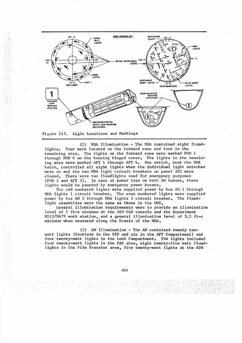
8/8/2019 MSFC Skylab Crew Systems Mission Evaluation
http://slidepdf.com/reader/full/msfc-skylab-crew-systems-mission-evaluation 184/397
Ill) -Z VIIW LOOKING AFT WARDROOM IIIII -Z_._6 I_ /'-'- UPP[R LIGHTS _ _ _
3 S ,* (I -Y
_:) INITI AL ENTRY/ EMER (IV)*YIt :_ J .I • __- LIG._ _ _.. _ ",3_L.'_/I
2 1 §
(,oz _---ourr, CO_,';T_,'_;;TS---/ _--SL_E_'coMrrFWO COMII'T' CREW QUARTERS LIGHTS
___ LOCATIONS__ //
Figure 117. Light Locations and Markings
(2) MgA Illumination - The I_A contained eight flood-
lights. Four were located on the forward cone and four in theremaining area. The lights on the forward cone were marked FWD I
through FWD 4 on the housing hinged cover. The lights in the remain-
ing area were marked AFT i through AFT 4. One switch, near the MDA
hatch, controlled all eight lights when the individual light switches
were on and the two MDA light circuit breakers on panel 202 were
closed. There were two floodlights used for emergency purposes
(l_qD 2 and AFT 3). In case of power loss on both AM busses, these
lights would be powered by emergency power busses.
The odd numbered lights were supplied power by bus AM i through
_)A lights I circuit breaker. The even numbered lights were supplied
power by bus AM 2 through MDA lights 2 circuit breaker. The flood-
light assemblies were the same as those in the OWS.
General illumination requirements were to provide an illumination
level of 5 ft-c minimum at the ATM C&D console and the Experiment
M512/M479 work station, and a general illumination level of 3.5 ft-c
minimum when measured along the X-axls of the MDA.
(3) AM Illumination - The AM contained twenty ten-
watt lights (fourteen in the STS and six in the AFT Compartment) and
four twenty-watt lights in the Lock Compartment. EVA lights included
four twenty-watt lights in the FAS area_ eight twenty-five watt flood-
lights in the Film Transfer area_ five twenty-watt lights at the ATM
160
8/8/2019 MSFC Skylab Crew Systems Mission Evaluation
http://slidepdf.com/reader/full/msfc-skylab-crew-systems-mission-evaluation 185/397
Center Work Station and seven twenty-watt lights at the Sun End Work
Station. All of the above were incandescent lights. Two of the STS
lights and one lock compartment light were utilized as emergency
lighting and would have been activated upon failure of both AM busses.
The two STS emergency lights were Instrument Panel Flood Lights
Number 8 and Number I0. The lock compartment emergency light wasNumber 4.
General illumination requirements were to equal or exceed 5 ft-cat 3-feet from the source of illumination in all habitable areas. EVA
lighting was to provide a minimumof 2 ft-c at 3-ft from the source of
illumination along EVA routes and 5 ft-c at 3-ft from the source of
illumination on EVA work surfaces.
b. Post Mission Assessment - The crew used the illumination
system during all missions, as anticipated, and all equipment operated
in a normal manner. The crew reported that_ during the work day, theyusually had all of the lights turned on "HIGH" all of the time. All
of the lights were usually turned off at night. On several occasions,lights were left on as night lights in the forward part of the cluster
(AM, MDA, etc).
It was also noted that the crew used the head mounted lamp from
the medical kit to perform certain maintenance tasks. This light
provided sufficient illumination and was used particularly in theunlighted plenum area.
There were no reported anomalies associated with the OWS and
AM illumination systems during the missions, other than some lamp
replacements in the AM. An anomaly occurred in the MDA when Aft
lights 2 and 4 went out. While performing the malfunction procedurepit was found that the switch on Panel 207 was intermittent. This
was corrected by taping the switch closed. The power shortage,
caused by the SAS problem on the first mission, required that power beconserved whenever possible. Use of the lighting system was therefore
kept to an absolute minimum until EVA SAS deployment. During the
second mission, light use was restricted in order to reduce OWS tempera-ture during the high beta angles.
The illumination system operated as designed during the missions.
Comments indicated that the crew considered the overall system to be
adequate for its intended purpose with the following exceptions:
(I) for closeup work like repair of items, (2) for shaving, and (3)for reading in the sleep quarters. The opinion of the crewmen was
that the overall light levels should have been higher. The crews
thought that the AM had the best lighting in the cluster and the EVA
lighting was rated excellent. The crews thought it would have been
highly desirable to have had fixed illumination in the plenum area.
The only expendables used were the bulb replacements in the AM.
Less than 10% of the 120 AM spare bulbs were used.
Spotmeter readings of luminance levels in foot-Lamberts were
obtained during the second mission and are listed in Table 17. CEI
161
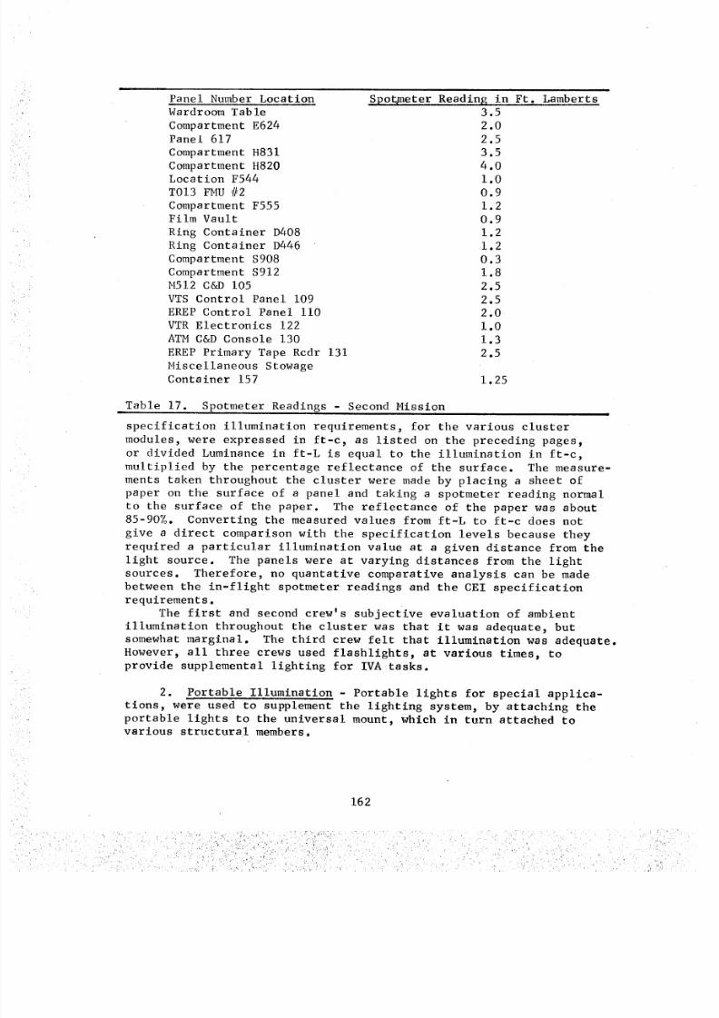
8/8/2019 MSFC Skylab Crew Systems Mission Evaluation
http://slidepdf.com/reader/full/msfc-skylab-crew-systems-mission-evaluation 186/397
Panel Number Locationi
Spot_neter Reading in Ft. LambertsWardroom Table
Compartment E624Panel 617
Compartment H831
Compartment H820Location F544
T013 FMU #2
Compartment F555Film Vault
Ring Container D408
Ring Container D446
Compartment $908
Compartment $912
M512 C&D 105
VTS Control Panel 109
EREP Control Panel ii0
VTR Electronics 122
ATM C&D Console 130
EREP Primary Tape Rcdr 131
Miscellaneous StowageContainer 157
3.5
2.0
2.5
3.5
4.01.0
0.9
1.2
0.9
1.2
1.2
0.3
1.8
2.5
2.5
2.0
1.0
1.3
2.5
1.25
Table 17. Spotmeter Readings - Second Mission
specification illumination requirements, for the various cluster
modules, were expressed in ft-c, as listed on the preceding pages_
or divided Luminance in ft-L is equal to the illumination in ft-c,
multiplied by the percentage reflectance of the surface. The measure-
ments taken throughout the cluster were made by placing a sheet of
paper on the surface of a panel and taking a spotmeter reading normal
to the surface of the paper. The reflectance of the paper was about
85-90%. Converting the measured values from ft-L to ft-c does not
give a direct comparison with the specification levels because they
required a particular illumination value at a given distance from the
light source. The panels were at varying distances from the light
sources. Therefore, no quantative comparative analysis can be made
between the in-flight spotmeter readings and the CEI specificationrequirements.
The first and second crew's subjective evaluation of ambient
illumination throughout the cluster was that it was adequate, but
somewhat marginal. The third crew felt that illumination was adequate.
However, all three crews used flashlights, at various times, to
provide supplemental lighting for IVA tasks.
2. Portable Illumination - Portable lights for special applica-
tions, were used to supplement the lighting system, by attaching the
portable lights to the universal mount, which in turn attached tovarious structural members.
162
. , _ i _i '_ _L'_ "
k
• . r,-
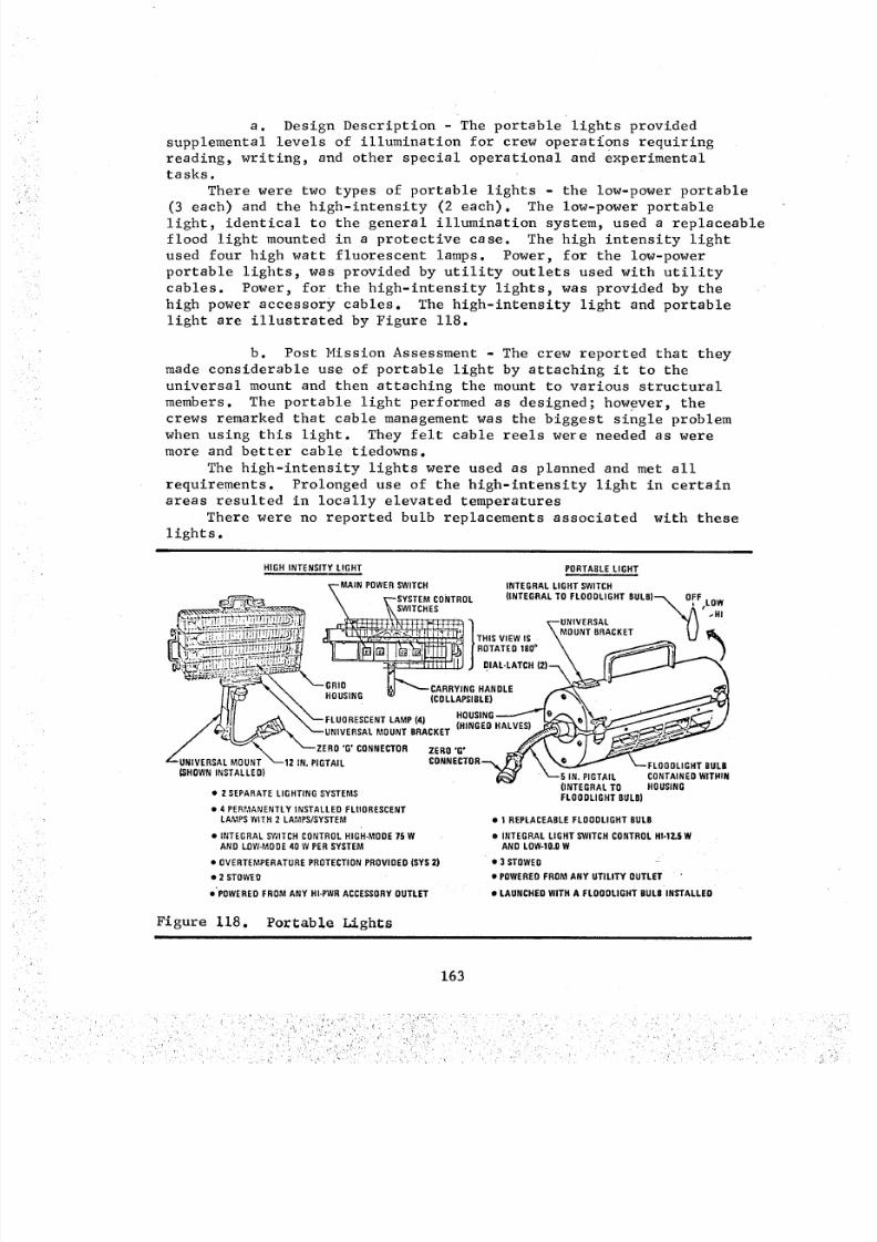
8/8/2019 MSFC Skylab Crew Systems Mission Evaluation
http://slidepdf.com/reader/full/msfc-skylab-crew-systems-mission-evaluation 187/397
a. Design Description - The portable lights provided
supplemental levels of illumination for crew operations requiring
reading, writing, and other special operational and experimental
tasks.
There were two types of portable lights - the low-power portable
(3 each) and the high-intensity (2 each). The low-power portable
light, identical to the general illumination system, used a replaceable
flood light mounted in a protective case. The high intensity light
used four high watt fluorescent lamps. Power, for the low-power
portable lights, was provided by utility outlets used with utility
cables. Power, for the high-intensity lights, was provided by the
high power accessory cables. The high-intensity light and portable
light are illustrated by Figure 118.
b. Post Mission Assessment - The crew reported that they
made considerable use of portable light by attaching it to the
universal mount and then attaching the mount to various structural
members. The portable light performed as designed; however, the
crews remarked that cable management was the biggest single problem
when using this light. They felt cable reels were needed as were
more and better cable tiedowns.
The high-intensity lights were used as planned and met all
requirements. Prolonged use of the high-intensity light in certain
areas resulted in locally elevated temperatures
There were no reported bulb replacements associated with these
lights.
HIGH INTENSITY LIGHT PORTABLE LIGHT
_--MAIN POWER SWITCH INTEGRAL LIGHT SWITCH
eD_ \ r--SYSTEM CONTROL (INTEGRALTOFLOODLIGHTBULB)_ OFFLOW
,,,_-_-___ \ _ SWITCHES _ t_' HI___ ___,\_+_ _ _ ,--ONIVERSA, "/\ "_;"__-_---__ ._=____-_'J / -r.,_,,,_,,,_ \MOUNTRAC,_ET _ /
__ ._---_,,,,, ,,, J,AL-LcARRY,NG.TCH,)_.__/ I_'_" NN HOUSING w (COLLAPSIBLE) f e_\
/ - \ "--ZERO'G'ONNECTOREHO'G' _ \ -J'_'UNIVERSALMOUNT "---12 IN.PIGTAIL CONNECTOR_ _ e%,,,.o..,__._._ _---FLOOOLIGHTBULB
(_I/__AI NEDWITHINSHOWN INSTALLED)
(INTEGRAL TO HOUSING• 2 SEPARATE LI GHTING SYSTEMS
• 4 P ER MA NE NTLY I NS TA LL ED F LU ORE SCE NT
LAMPS WITH 2 LAMPS/SYSTEM
• INTEGRAL SWITCH CONTROL HIGH-MODE 75 W
AND LOW-MOOE 40 W PER SYSTEM
• OV ERT EM PE RAT URE P RO TEC TI ON PR OVI DE D (S YS 2)
• 2 STOWED
• "P OWER ED F RO M A NY HI -P WR A CCE SSO RY O UTL ET
FLOODLIGHTULB)
• 1 REPLACEABLELOODLIGHTULB• INTEGRALLIGHTSWITCHCONTROLHI.IZ.§W
ANDLOW-10.OW
• 3 STOWED ":
• POWEREDROMANYUTILITYOUTLET "
• LAUNCHEDWITHA FLOODLIGHTBULB NSTALLED
Figure 118. PorCable Lightsi
163
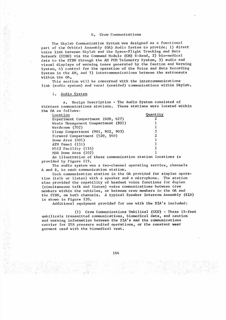
8/8/2019 MSFC Skylab Crew Systems Mission Evaluation
http://slidepdf.com/reader/full/msfc-skylab-crew-systems-mission-evaluation 188/397
N. Crew Communications
The Skylab Communication System was designed as a functional
part of the Orbital Assembly (OA) Audio System to provide; I) direct
voice link between Skylab and the Space-Flight Tracking and DataNetwork (STDN) via the Command Module (CM) S-Band, 2) bio-medical
data to the STDN through the AM PCM Telemetry System, 3) audio and
visual displays of warning tones generated by the Caution and Warning
System, 4) control for the operation of the Voice and Data Recording
System in the AM, and 5) intercommunications between the astronautswithin the OA.
This section will be concerned with the intercommunications
link (audio system) and vocal (unaided) communications within Skylab.
i. Audio System
a. Design Description - The Audio System consisted of
thirteen communications stations. These stations were located within
the OA as follows:
Location
Experiment Compartment (600, 627)
Waste Management Compartment (801)
Wardroom (702)
Sleep Compartment (901, 902, 903)
Forward Compartment (520, 540)
Dome Area (401)
ATM Panel (131)
M512 Facility (116)
MDA Dome Area (102)
Quantity
21
1
3
2
i
I
I
i
An illustration of these communication station locations is
provided by Figure 119.
The audio system was a two-channel operating service, channels
A and B, to each communication station.Each communication station in the OA provided for simplex opera-
tion (talk or listen) with a speaker and a microphone. The station
also provided the capability of headset voice functions for duplex
(simultaneous talk and listen) voice communications between crew
members within the vehicles, or between crew members in the OA and
the STDN, on both channels. A typical Speaker Intercom Assembly (SIA)
is shown in Figure 120.
Additional equipment provided for use with the SIA's included:
(I) Crew Communications Umbilical (CCU) - These 15-feet
umbilicals transmitted communications, biomedical data, and caution
and warning information between the SIA's and the communications
carrier for IVA pressure suited operations, or the constant wear
garment used with the biomedical vest.
164
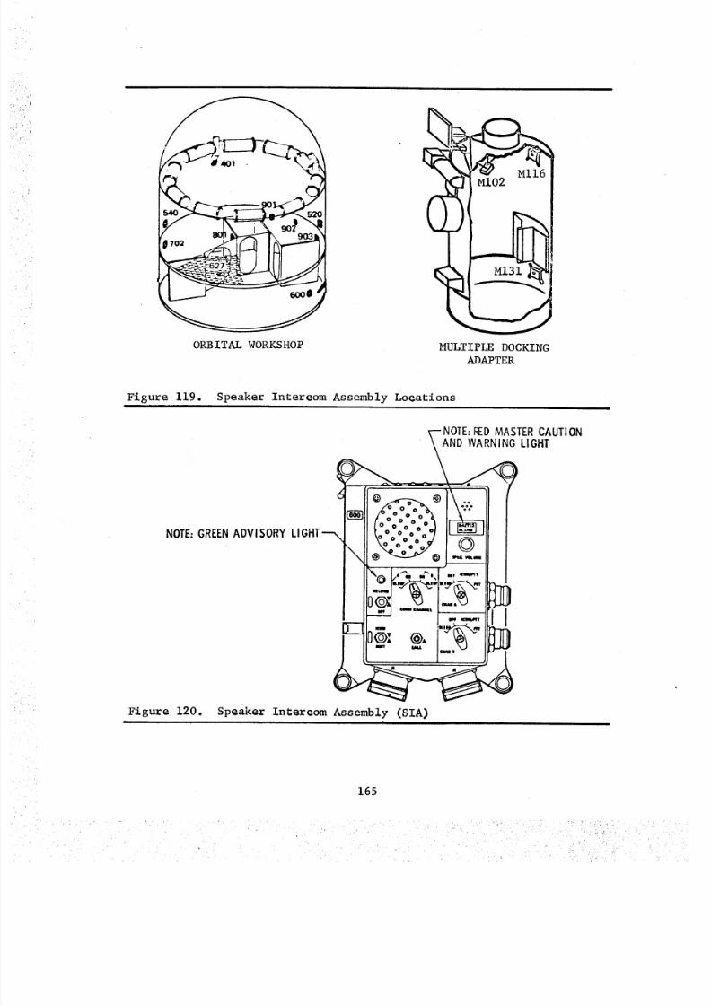
8/8/2019 MSFC Skylab Crew Systems Mission Evaluation
http://slidepdf.com/reader/full/msfc-skylab-crew-systems-mission-evaluation 189/397
/
ORBITAL WORKSHOP MULTIPLE DOCKING
ADAPTER
Figure 119. Speaker Intercom Assembly Locations
NOTE:RED MASTER CAUTIONAND WARNING LIGHT
\
NOTE: GREEN ADVISORY LI
Figure 120. Speaker Intercom Assembly (SIA)=i •
165
8/8/2019 MSFC Skylab Crew Systems Mission Evaluation
http://slidepdf.com/reader/full/msfc-skylab-crew-systems-mission-evaluation 190/397
8/8/2019 MSFC Skylab Crew Systems Mission Evaluation
http://slidepdf.com/reader/full/msfc-skylab-crew-systems-mission-evaluation 191/397
initiation caused loss of the green recording light on the SIA, poorcoordination occasionally occurred. To avert the loss of AM tape
recorder data/information, system design should prevent simultaneous
tape recorder dump and crew operation.
A malfunction of a hand-held microphone occurred. The mike was
subsequently marked with red tape and stowed. The crew consideredthe microphone a desirable item and recommended that replacements be
brought up with the third crew. It was also reported, at the Crew
System Debriefing, that the second mission crew replaced the SIA at
the -Z SAL because the transmit switch had failed in the ON position.
With the exception of the acoustic feedback problems, the audio
system (crew interface portion) operated in a satisfactory manner.
Locations of SIA's within the 0WS was reported satisfactory, although
the SIA in the forward dome (401) was not used. Volume level was also
described as satisfactory.
Use of the headset did not disable the speaker in the SIA and
caused interference and annoyance with other crew activities.
Communications performance with the umbilicals was satisfactory;
however, cable stiffness tended to dislodge the lightweight headset
from the crewman's head. The major portion of communications directlyutilized the speaker intercom boxes.
2. Vocal (Unaided) Communication - There is no hardware associ-ated with this assessment other than the acoustical characteristics
created by the entire configuration of the OA. It is, therefore, an
evaluation of the oral and vocal communication results and peculiarities
that currently exist in the zero-g and reduced pressure equivalent.Unaided voice communication was somewhat difficult within the
OWS. One could be heard in the OWS from the MDA if one shouted veryloudly, but normal voice communication from the OWS to the MDA was
impossible. The crew concluded that this condition was due to poorsound transmission (a function of 5-psi pressure levels) rather thanto noise interference. Noise levels were considered low within the
spacecraft.
The voice communication, in confined areas such as the Wardroom,
was considered by the crew to be like "right here", although there
was a tendency to get "close to the guy you were talking to." Unaided
voice communication from the Wardroom or Experiment Compartment to
the dome area was possible, but required "yelling".
167
8/8/2019 MSFC Skylab Crew Systems Mission Evaluation
http://slidepdf.com/reader/full/msfc-skylab-crew-systems-mission-evaluation 192/397
8/8/2019 MSFC Skylab Crew Systems Mission Evaluation
http://slidepdf.com/reader/full/msfc-skylab-crew-systems-mission-evaluation 193/397
and a tool kit check performed in the High Fidelity Mockup at MSFC
and recommendations transmitted to JSC. No report of crew action
relative to this problem was reported. The second crew also reported
that this same switch was loose. The crew reported that they would
fix it, but no verification was received. This same problem also
recurred during the third mission, but no fix was attempted. Thecrew decided that, during future usage, they would verify that the
rotary switch was all the way to the "A" (Stop) position, and then
count to the desired position to make certain that the switch was
properly positioned.There were no specific adverse or critical crew comments relative
to the assessment of the OWS controls and displays. The first crewindicated that the concept of wickets and partial recess, which was
used, was a good compromise toward switch and circuit breaker protec-
tion. The second crew commented that finger clearances between
wickets and switches/circuit breakers were adequate. The third crew
made no specific comment relative to OWS controls and displays.
Therefore, it is concluded that the overall layout, arrangement,
groupings, etc. of the OWS controls and displays proved to be adequate
and acceptable for all missions.
169
8/8/2019 MSFC Skylab Crew Systems Mission Evaluation
http://slidepdf.com/reader/full/msfc-skylab-crew-systems-mission-evaluation 194/397
B. Airlock Module
i. Design Description - Control and display mechanization for
the AM was unique. All other U. S. spacecraft had been designed
exclusively for either manned or unmanned operation. The AM was
designed for both. The AM C&D panels provided the crew option of
ground control (via DCS) or onboard control of Skylab systems and
equipment. The primary control capability was thus vested onboard
during the manned phases. The crew had the option of relegating
control of various components within a given system to DCS. Equipment
and controls, unique to manned mission phases (fans, lighting, mole-
cular sieves), had conventional mechanization with only onboard
controls capability. Conversely, some functions that did not effect
manned phases, such as 2-watt transmitter selection, had only ground
control capability. Controls for remotely mounted systems and equip-
ment were located on the main STS C&D panel along with displays which
provided operating information or feedback to the crew.
Panels and controls were numbered to facilitate communication anddocumentation reference. The numbering system started with i00 series
numbers for the forward end of the vehicle (MDA) and ran to i000 seriesnumbers in the OWS aft areas. The AM used 200 series numbers in the
STS and 300 series numbers through the tunnel section for panel identi-
fication.
All circuit breakers for AM power were located on panels 200,
201 and 202 on AMS 157 bulkhead. The circuit breakers, as were all
other panels, were protected by bar guards which provided operatingreaction points, minimized inadvertent operations, and allowed visual
assessment of circuit breaker position. Circuit breaker arrangements
on each panel were grouped by function and system. Color coded bandsbeneath the breakers denoted the bus from which e_ch breaker derived
its power. The color code was also depicted in the Bus Distribution
schematic on panel 211.
Schematic diagrams were superimposed directly on control panels,
where panel space allowed. Where a panel was insufficient or controls
seldom used, functional flow diagrams were located on adjacent areas.
Control positions were shown by indicator lights for momentary
switches or detents and pointers for valves and rotary switches.
Special tools needed for control operation were tethered adjacent to
the required location. Controls requiring unusual manipulation were
marked with operating instructions.
Controls and displays were located throughout the AM to provide
crew operational capability near the equipment being operated or
controlled. Thus, perceptible cues to equipment operating status,such as fan start up or compartment venting, could be easily detected
at the control operating position.
The combination of main AM C&D panel and ECS equipment in the STS
provided a crew station arrangement where all system interactions
(cluster attitude, EPS, ECS, C&W, etc) and control responses could be
ascertained at a single control station.
170
L
8/8/2019 MSFC Skylab Crew Systems Mission Evaluation
http://slidepdf.com/reader/full/msfc-skylab-crew-systems-mission-evaluation 195/397
Caution and Warning (C&W) contained visual annunciators and in-
hibit/enable switches for redundant sensors. C&W generated audible
alarm tones were transmitted by the AM audio system to the SIA
speakers and the low level audio systems. Emergency tones for fire
or rapid Delta-P were sounded by klaxons independent from the AM
audio system. Audio levels were adjustable by controls on panel 207.
Individual C&W sensors could be inhibited by the inhibit/enable
switches to prevent repeated false alarms by malfunctioned sensors.
These switches also allowed parameter isolation for trouble shootingwhere one visual annunciator was used for multiple parameters. The
fire alarm system was mechanized to allow replacement and adjustment
of individual sensors without triggering the emergency alarms in C&W.
Lever lock type toggle switches were used on control panels in
the EVA lock compartment and on critical functions in the STS. The
EVA panels used lever lock switches to prevent unintentional controls
operation due to the limited mobility and field-of-view of a suitedcrewman.
AM meters were universal indicators that would interface with
different transducers with change only to scale and internal resistance
required. The meter scale was stepped to put the needle and scale
in one plane and eliminate parallax. The scale was translucent white
with black graduations which provided easy viewing by meter internal
illumination or by ambient cabin lights. All AM meters were locatedadjacent to their related controls.
Color coding of selected AM controls was used to emphasize the
specific nature of those controls to the crew. Emergency controls or
crew interface was indicated by aviation red (i.e., fire extinguisherports).
A black and yellow cautionary striped band denoted a crew inter-
face that should be used with caution and adequate preparation
(i.e., lock compartment depressurization valve). Items to be discarded
on activation were painted green. In addition, a variety of anodized
aluminum decals and markers were used to emphasize critical crew
interface and provide easy visual identification of similar connectors
whose functlons were not interchangeable. While not actually a color
code, black or white stripes were used on all crew operated electrical
connectors to show major keyway locations.
2. Post Mission Assessment - AM C&D arrangement in Skylab was
based on a combination of judgments by experienced spacecraft engineers
and empirical data drawn from previously successful Mercury and Gemini
programs. The unique and unprecedented long term habitability require-ments of Skylab, coupled with revisits by different crews with somewhat
different mission goals, provided an unequalled opportunity to evaluate
the performance of C&D design in a single vehicle by crews of varied
technical backgrounds, interest, personalities and capability levels.
Thus, any criticism, common to separate crews, should indicate the
need for serious evaluation and design investigation.
171
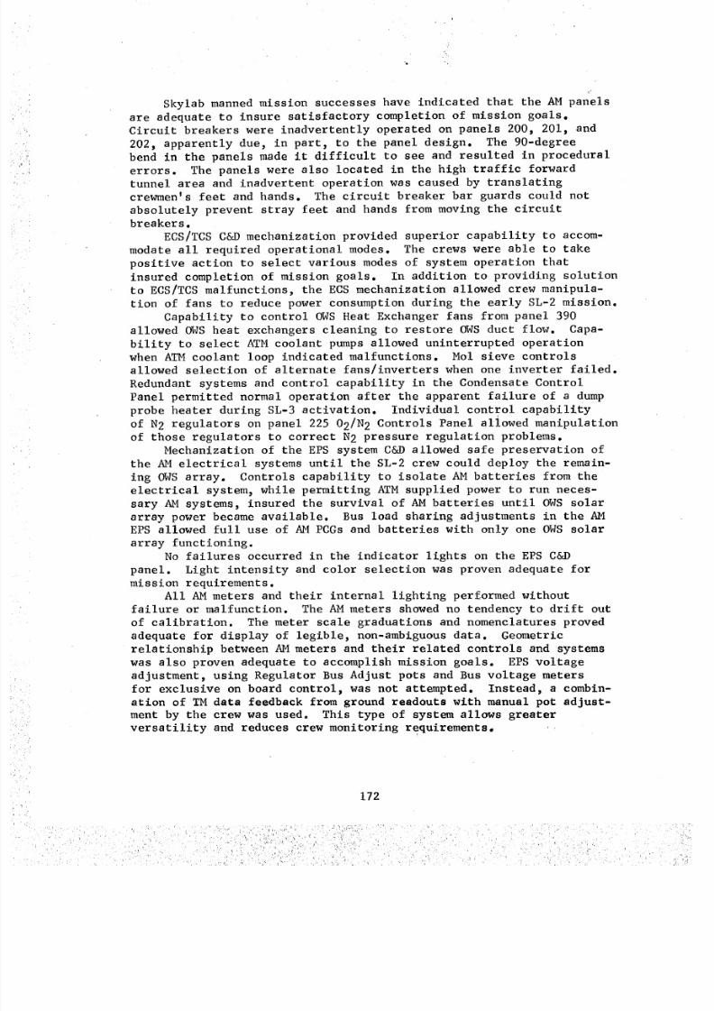
8/8/2019 MSFC Skylab Crew Systems Mission Evaluation
http://slidepdf.com/reader/full/msfc-skylab-crew-systems-mission-evaluation 196/397
_!
Skylab manned mission successes have indicated that the AM panels
are adequate to insure satisfactory completion of mission goals.Circuit breakers were inadvertently operated on panels 200, 201, and
202, apparently due, in part, to the panel design. The 90-degreebend in the panels made it difficult to see and resulted in procedural
errors. The panels were also located in the high traffic forward
tunnel area and inadvertent operation was caused by translating
crewmen's feet and hands. The circuit breaker bar guards could not
absolutely prevent stray feet and hands from moving the circuitbreakers.
ECS/TCS C&D mechanization provided superior capability to accom-
modate all required operational modes. The crews were able to take
positive action to select various modes of system operation that
insured completion of mission goals. In addition to providing solution
to ECS/TCS malfunctions, the ECS mechanization allowed crew manipula-
tion of fans to reduce power consumption during the early SL-2 mission.
Capability to control OWS Heat Exchanger fans from panel 390
allowed OWS heat exchangers cleaning to restore OWS duct flow. Capa-bility to select ATM coolant pumps allowed uninterrupted operation
when ATM coolant loop indicated malfunctions. Mol sieve controls
allowed selection of alternate fans/inverters when one inverter failed.
Redundant systems and control capability in the Condensate Control
Panel permitted normal operation after the apparent failure of a dump
probe heater during SL-3 activation. Individual control capability
of N2 regulators on panel 225 02/N 2 Controls Panel allowed manipulation
of those regulators to correct N 2 pressure regulation problems.
Mechanization of the EPS system C&D allowed safe preservation of
the AM electrical systems until the SL-2 crew could deploy the remain-
ing OWS array. Controls capability to isolate AM batteries from the
electrical system, while permitting ATM supplied power to run neces-
sary AM systems, insured the survival of AM batteries until OWS solar
array power became available. Bus load sharing adjustments in the AMEPS allowed full use of AM PCGs and batteries with only one OWS solar
array functioning.
No failures occurred in the indicator lights on the EPS C&D
panel. Light intensity and color selection was proven adequate for
mission requirements.All AMmeters and their internal lighting per£ormed without
failure or malfunction. The AM meters showed no tendency to drift out
of calibration. The meter scale graduations and nomenclatures proved
adequate for display of legible, non-ambiguous data. Geometric
relationship between AMmeters and their related controls and systems
was also proven adequate to accomplish mission goals. EPS voltageadjustment, using Regulator Bus Adjust pots and Bus voltage meters
for exclusive on board control, was not attempted. Instead, a combin-
at£on of TM data feedback from ground readouts with manual pot adjust-
ment by the crew was used. This type of system allows greater
versatility and reduces crew monitoring requirements,
172
8/8/2019 MSFC Skylab Crew Systems Mission Evaluation
http://slidepdf.com/reader/full/msfc-skylab-crew-systems-mission-evaluation 197/397
Audible alarms genersted by C&W were suitable for anticipated
orbit conditions. Alarm loudness adjustments on panel 207 were avail-
able had the interior operating noise levels in Skylab required adjust-
ment of alarm audio levels. The preset sound levels, coupled with
SIA and Klaxon locations, provided complete coverage of the orbital
cluster without causing physical hearing damage to the crews. Visualalarms and annunciators in the C&W system were adequate to initiate
proper crew reaction and provide system trouble-shooting capability.The sensor isolation capability, made possible by the inhibit/enable
switches, eliminated false alarms from a drifting duct flow sensor
and eased EVA prep time requirements by quick isolation of tunnel
fire sensors.
For future manned spacecraft, circuit breakers, or any controls,
should be separated from paths of high crew traffic. Also, physical
operation of AM breakers is similar to toggle lever switches. Opera-tion of these breakers requires access from two opposite sides of the
breaker. Consideration should be given to push-pull type breakers
for selected applications.
However, if a circuit breaker is to be used regularly for switch-
ing functions, the toggle type lever is superior to the push,pullactuation.
Organization of Skylab electrical power system controls physically
separate the AM EPS from ATM CBRM controls. The C&D design of the
two electrical power systems is very different. Since both control
sets perform quite similar functions, some crew training time and
on-orbit operational time could have been saved if the systems used
a common control panel and similar or identical C&D design andmechanization.
The lack of controls malfunction in the AM EPS indicates possible
advantages in its C&D design. Displays in the AM EPS could be improved
to enhance on-board fine adjustment of AM bus voltages by the additionof a meter "scaling switch" that would expand meter sensitivity andscale.
A manual backup (bypass, or control) for critical automatic con-
trol functions should be mandatory for all C&D mechanizations. This
is normal aircraft and spacecraft design practice which would have
been useful for coolant loop temperature control. A central servicing
location for both coolant loops internal to the vehicle would have
greatly reduced the effort required to generate an on-orbit reserviee
technique.
For spacecraft with long orbital lifetime, design parameters for
on-orbit repairs and servicing requirements must be included in the
mechanization and arrangement of vehicle controls and displays. An
on-orbit maintenance plan for all critical systems should be designed
into the vehicle, even with redundant systems.
Caution and Warning parameters provided in Skylab were large in
number and included some items that recent orbital operations have
shown to be unnecessary: "Duct-Flow" for the gas interchange duct
173
• i̧ _.:'_
8/8/2019 MSFC Skylab Crew Systems Mission Evaluation
http://slidepdf.com/reader/full/msfc-skylab-crew-systems-mission-evaluation 198/397
could be replaced with fluttering strips of paper or eliminatedentirely, since stagnant gas pockets have proven to be no problem aslong as some air mass flow is available. The emergency fire warning
system differs from the rest of the C&W system. This difference
(remote sensors & control panels) required added crew training, in
locating and silencing the alarms. The audible alarms must be
silenced for good crew communication and the difference between
silencing a fire alarm and other audible alarms could cause confusian.
The memory system for "emergency" parameters should be similar to that
of other C&W parameters.
Internal lighting for AMmeters, based on Skylab experience, was
proved unnecessary. In applications such as Skylab, where the
operating crewman did not have to change visual field from outsidethe vehicle to inside the vehicle (i.e., docking and station keeping
in CSM), internally lighted meters are not required.
174
8/8/2019 MSFC Skylab Crew Systems Mission Evaluation
http://slidepdf.com/reader/full/msfc-skylab-crew-systems-mission-evaluation 199/397
C. Apollo Telescope Mount
i. Design Description - The Apollo Telescope Mount Control and
Display Panel, Figure 121, was designed to perform sophisticated
astronomy observations using seven telescope assemblies. It repre-
sents the most complex scientific control and display console flownin an orbital mission.
During operation of the astronomy observation experiments,
specific operational problems occurred in connection with the panel's
controls and displays, as is evidenced by mission data from SL-2,
SL-3, and SL-4. These problems are described in ensuing paragraphs,in order to pinpoint those problem areas where man/system interfaces
show operational inadequacy. Subjective crew comments and an in-depth
analysis of SL-2 telemetry data were used to study the panel design
features which contributed to operational problems. In some instances,
these design problems are specifically identified with the objectivethat similar mistakes be avoided on future missions (i.e., on Shuttlepayload control panels).
2. Experiment Interface Evaluation - The experiment interface
area represents the highest area of operational activity, in that the
performance of the operational procedures (building blocks) is
centered around this functional area. This accounts for the fact
that the same area is the location of the highest number of man/machine
interface problems. The information below presents the subjective
comments obtained from real-time crew comments, crew voice transcripts
and debriefings. These comments are not intended to be a judgment of
design adequacy or inadequacy but, rather, to identify obvious prob-
lem areas and prevent their recurrence in future designs.
a. Hydrogen Alpha Telescopes i and 2 - The man/system
interface problems incurred during the Ha experiment, Figure 122,
were relatively minor. The most significant problem dealt with opera-tion of the Hal mode (frames/minute) switch. The crew cited numerous
instances when they had left the MODE SELECT switch (3 position toggleswitch) in the wrong position.
I orr --CLOSE-- _ IOVE..,DEI I .A. I sEc ,
Figure 122. Hydrogen Alpha Telescopes 1 and 2 C&DI
Two causal factors for this occurrence have been postulated.
First, the frames/minute mode is controlled by a three position toggle
switch, but other experiment mode switches are rotary types. The
specific problem associated with a toggle switch is that determination
175
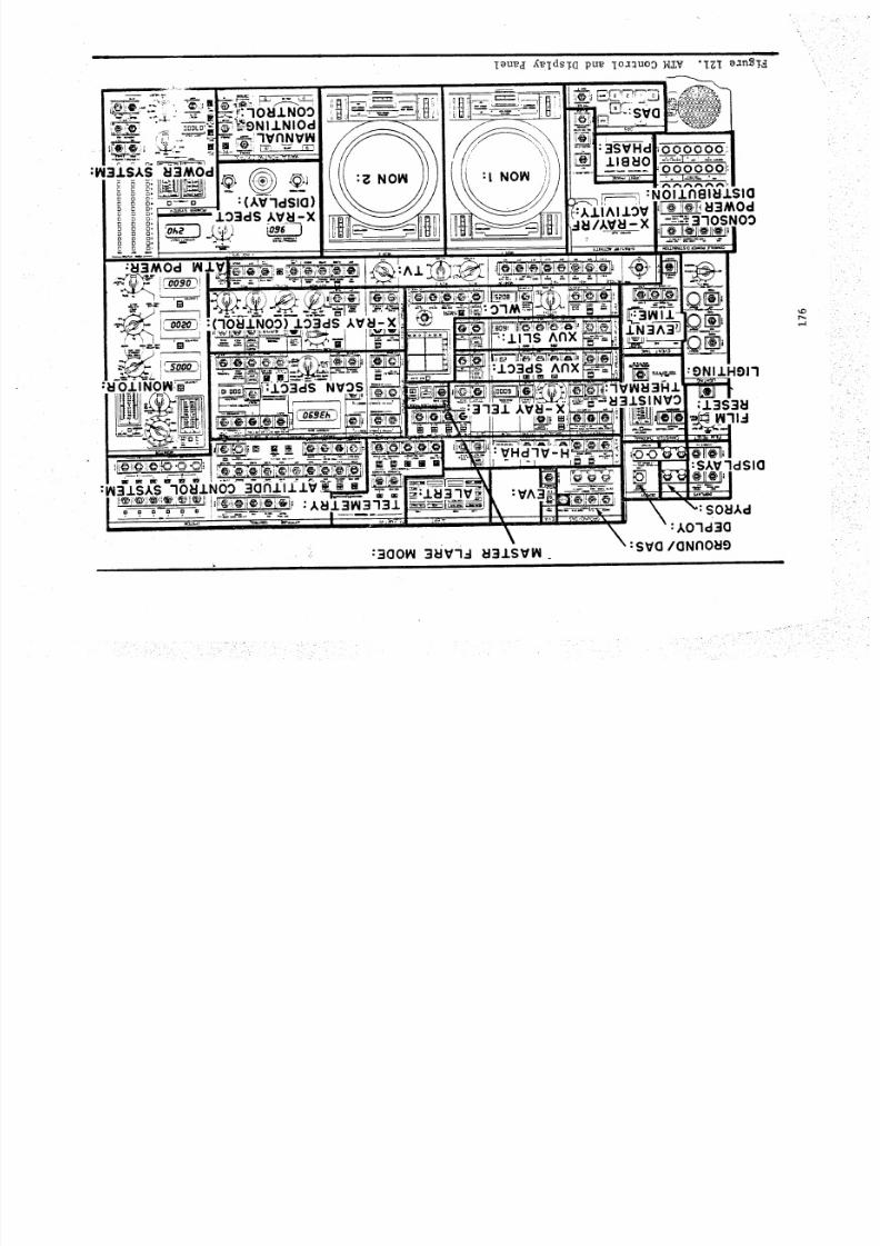
8/8/2019 MSFC Skylab Crew Systems Mission Evaluation
http://slidepdf.com/reader/full/msfc-skylab-crew-systems-mission-evaluation 200/397
I
leu_H X_idsia pu_ ioa_uoo H_V "IZI _anSI_
:70_1N00 _ .--" ,__NIINIOd
,nNV_
: (AV7dSIQ): 103dS AV_I-Xo o. _._)
.17S Anx
lO':ldS ^nx
3731 AV_l- X
:VHd7V-H
:VA':I
i __
3SVH ooooo:118U0
000000
:NOllnel_lJ.Sla
AIIAllOV =_ _3h_OdI/AVU_-- X :3 )SNO3
:31NIl-
:SAV7dSIO
SOUXd
:AO7d3O
: SVO/ONnOUe
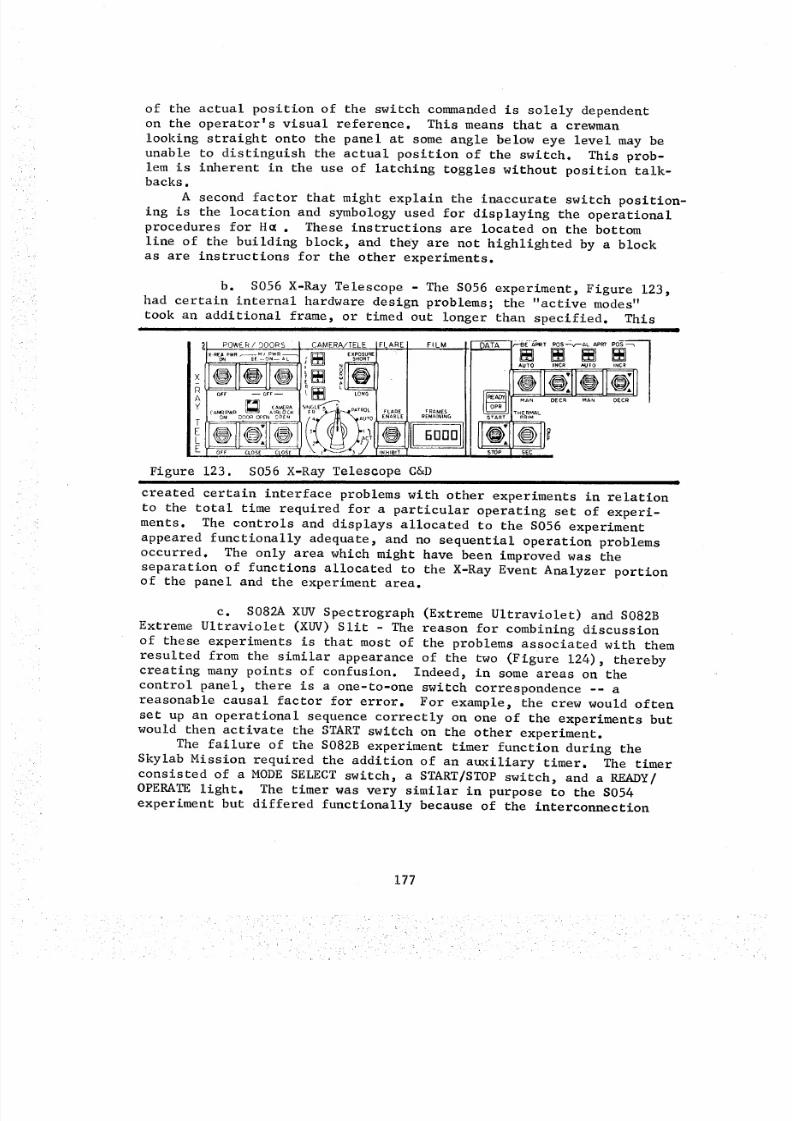
8/8/2019 MSFC Skylab Crew Systems Mission Evaluation
http://slidepdf.com/reader/full/msfc-skylab-crew-systems-mission-evaluation 201/397
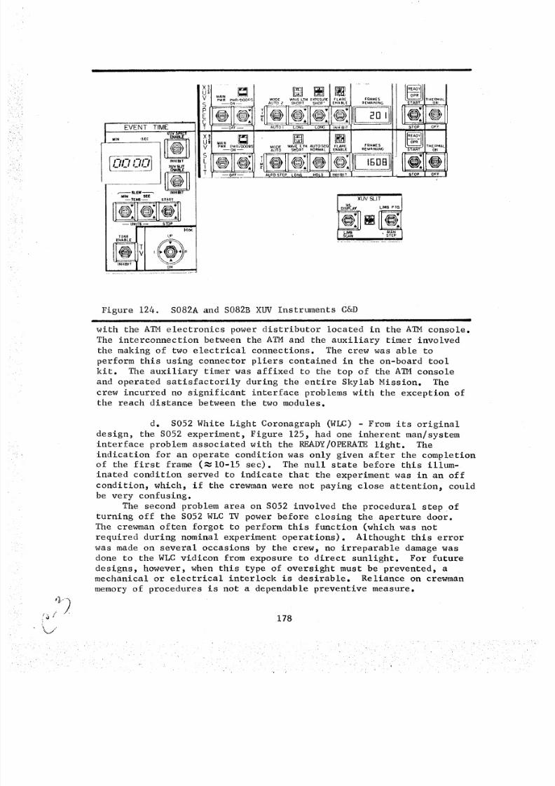
8/8/2019 MSFC Skylab Crew Systems Mission Evaluation
http://slidepdf.com/reader/full/msfc-skylab-crew-systems-mission-evaluation 202/397
EVENT TIME ,,UV SF_CT
MIN "SEC,_,I_1 ,_h_l
r------ .e,L_'W _
MIN_ TEi_ GE__C START
-- UNII_ -- STOP J
TONE LIPENABLE
t n
V MAINPWFI P'vVR/DOO Q c_
Spl
T
VSLtT
--ON----
--OFF --
MAIN []
PWR PWN IDOOR_
--ON-
-Of'F-
_OOE WAVE LTH [X_0$UqEAUTO _ SHORT SHOP +
T __ • --•
AUTO I LONG LONG
• []
.ARE fRAMESABLI REMAINING
HIBI
_ARE FRAMES
ABL_E REMAINING
_IB11
XUV SLIT 1
READY
_TART
U'START
STOP I
f I-IO#NMA L
0_
THEPMAL
ON
@
Figure 124. S082A and S082B XUV Instruments C&D
I I
with the ATM electronics power distributor located in the ATM console.
The interconnection between the ATM and the auxiliary timer involved
the making of two electrical connections. The crew was able to
perform this using connector pliers contained in the on-board tool
kit. The auxiliary timer was affixed to the top of the ATM console
and operated satisfactorily during the entire Skylab Mission. The
crew incurred no significant interface problems with the exception of
the reach distance between the two modules.
d. S052 White Light Coronagraph (WLC) - From its original
design, the S052 experiment, Figure 125, had one inherent man/system
interface problem associated with the READY/OPERATE light. The
indication for an operate condition was only given after the completion
of the first frame (_10-15 sec). The null state before this illum-
inated condition served to indicate that the experiment was in an off
condition, which, if the crewman were not paying close attention, could
be very confusing.
The second problem area on S052 involved the procedural step of
turning off the S052 WLC TV power before closing the aperture door.The crewman often forgot to perform this function (which was not
required during nominal experiment operations). Althought this error
was made on several occasions by the crew, no irreparable damage was
done to the WLC vidicon from exposure to direct sunlight. For future
designs, however, when this type of oversight must be prevented, a
mechanical or electrical interlock is desirable. Reliance on crewman
memory of procedures is not a dependable preventive measure.
178
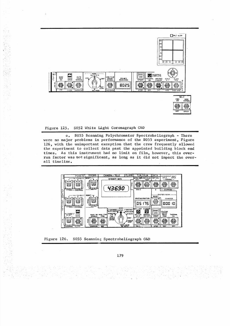
8/8/2019 MSFC Skylab Crew Systems Mission Evaluation
http://slidepdf.com/reader/full/msfc-skylab-crew-systems-mission-evaluation 203/397
II FMAIN AUTO _ LOW FILM
_ _IoN_PWI_ ODOR ODOR STD CONT NORMALINHIEllT --REMAININGFRAMES
I 'I IIQ21 AST
AN
LI I oo_ CLOSE,,e_n,Bq See,RD_ IOVEORmEI
F-I W LC A LI GN
I /ll sEou-cEC_4PLETE
THERMAL MIR PO$ SCALE AUGNI SL'_f_TRT I" ON CAMERA x l PTG O
S 0 _ OFF TV XfO DISC_AN 0
WLCPWR GRtO
ON NORMAL
jellQ.OFF OISCH
Figure 125. S052 White Light Coronagraph C&DI
e. S055 Scanning Polychromator Spectroheliograph - There
were no major problems in performance of the S055 experiment, Figure
126, with the unimportant exception that the crew frequently allowed
the experiment to collect data past the appointed building block end
times. As this instrument had no limit on film, however, this over-
run factor was not significant, as long as it did not impact the over-
all timeline.
POWER/HVENABLEI
HV ENABLE/
HV ENA_LF/ []
RESET DOOR
DOO,RS
RESE-T_-- s
RESET --
i • MODE _, IR L IM IT O -O RD ER.E_I._M l R RDR "i__ _TBp t- GRATiNG_ _
AUTO RASTER -- UTO
ENABLE PRIM LINE UP/R REFOPT
(I_VERRK)E _ _ INI_C_AP_ ( DNIL
CAMEP,A/TELE IFLARE; TLM/FILM IDATA I_V_OO_E×P.,S.TINTENErnf _T NTEN _d_'ADETELEC O_LT"SEL INTLK INTLK
A --BUSI TEST I , I --NORMAL--
L _'_ O_ U _ -- BUS2 3 I--OVERRIDE--
_ RASTER/SCAN--
RESET
gRATING PO6rTION ! _ COUNTER5 175 OOO I0
GRATff_GMOTOR
DRIVE THERMALI_IM ON
STOP SEC OFF
Figure 126. S055 Scannin_ Spectroheliograph C&D
179
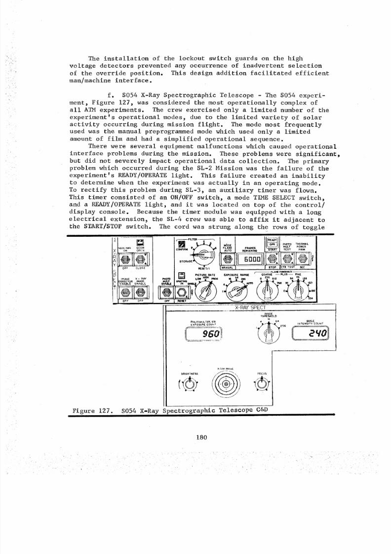
8/8/2019 MSFC Skylab Crew Systems Mission Evaluation
http://slidepdf.com/reader/full/msfc-skylab-crew-systems-mission-evaluation 204/397
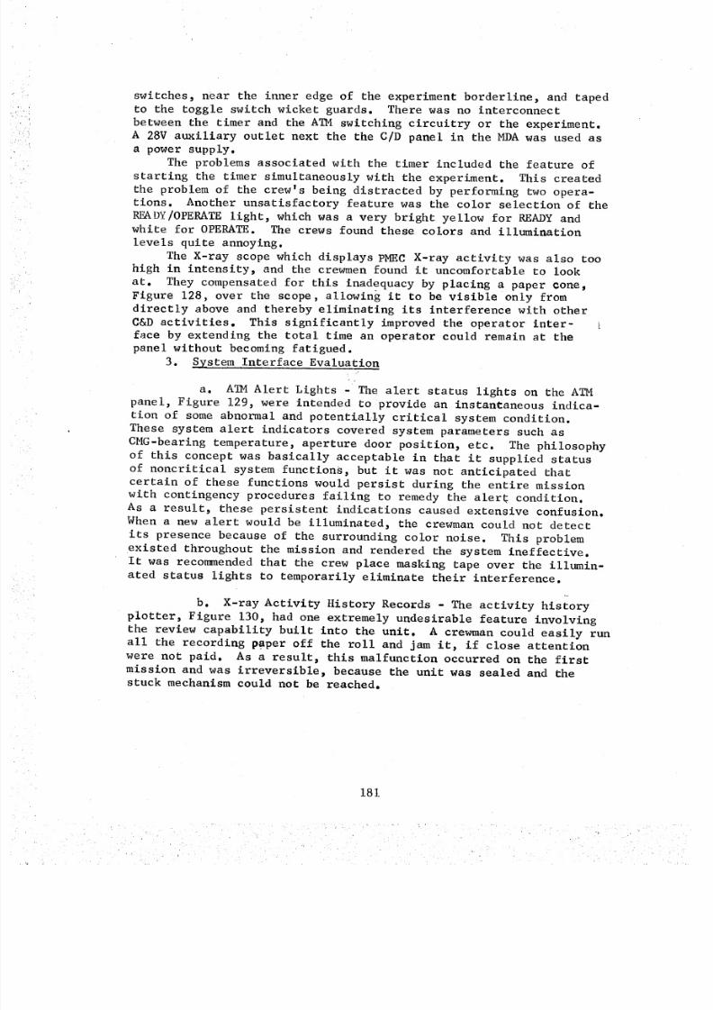
8/8/2019 MSFC Skylab Crew Systems Mission Evaluation
http://slidepdf.com/reader/full/msfc-skylab-crew-systems-mission-evaluation 205/397
switches, near the inner edge of the experiment borderline, and tapedto the toggle switch wicket guards. There was no interconnectbetween the timer and the ATMswitching circuitry or the experiment.A 28V auxiliary outlet next the the C/D panel in the MDAwas used asa power supply.
The problems associated with the timer included the feature ofstarting the timer simultaneously with the experiment. This createdthe problem of the crew's being distracted by performing two opera-tions. Another unsatisfactory feature was the color selection of theREADY/OPERATEight, which was a very bright yellow for READYandwhite for OPERATE.The crews found these colors and illuminationlevels quite annoying.
The X-ray scope which displays PMECX-ray activity was also toohigh in intensity, and the crewmenfound it uncomfortable to lookat. They compensatedfor this inadequacy by placing a paper cone,Figure 128, over the scope, allowing it to be visible only fromdirectly above and thereby eliminating its interference with otherC&Dactivities. This significantly improved the operator inter-face by extending the total time an operator could remain at thepanel without becoming fatigued.
3. System Interface Evaluation
, ,-
a. ATM Alert Lights - The alert status lights on the ATMpanel, Figure 129, were intended to provide an instantaneous indica-
tion of some abnormal and potentially critical system condition.
These system alert indicators covered system parameters such as
CMG-bearing temperature, aperture door position, etc. The philosophy
of this concept was basically acceptable in that it supplied status
of noncritical system functions, but it was not anticipated that
certain of these functions would persist during the entire mission
with contingency procedures failing to remedy the alert condition.As a result, these persistent indications caused extensive confusion.
When a new alert would be illuminated, the crewman could not detect
its presence because of the surrounding color noise. This problemexisted throughout the mission and rendered the system ineffective.
It was reconlnended that the crew place masking tape over the illumin-ated status lights to temporarily eliminate their interference.
b. X-ray Activity History Records - The activity history
plotter, Figure 130, had one extremely undesirable feature involving
the review capability built into the unit. A crewman could easily run
all the recording _aper off the roll and jam it, if close attention
were not paid. As a result, this malfunction occurred on the first
mission and was irreversible, because the unit was sealed and the
stuck mechanism could not be reached.
181
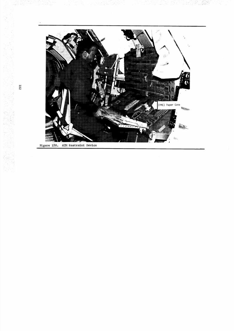
8/8/2019 MSFC Skylab Crew Systems Mission Evaluation
http://slidepdf.com/reader/full/msfc-skylab-crew-systems-mission-evaluation 206/397
k.
O0
Figure 128.
(PMC) Paper Cone
L
ATM Restraint Devi=e
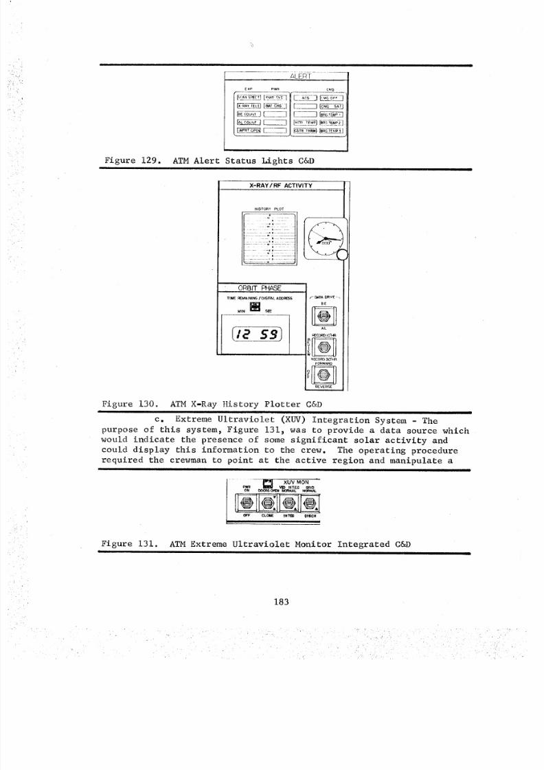
8/8/2019 MSFC Skylab Crew Systems Mission Evaluation
http://slidepdf.com/reader/full/msfc-skylab-crew-systems-mission-evaluation 207/397
4
Figure 129.
I
ExP PW_ [_G
=<f_T_TT
- _,_p .......
ATM Alert Status Lights C&D
X-RAY/RF ACTIVITY
HISTORY PLO T
ORBIT PHASE
TIME I_k_AINING / DIGITAL AOORESS
MIN [] S_
r_ DaTA DRIV_ - _
BE
_ECORD IO'HR
II <_> II
_ EC OR B _ O HR
I;tEVERSEi
Figure 130. ATM X-Ray History Plotter C&D
c. Extreme Ultraviolet (XUV) Integration System - The
purpose of this system, Figure 131, was to provide a data source which
would indicate the presence of some significant solar activity and
could display this information to the crew. The operating procedure
required the crewman to point at the active region and manipulate a
I ..... I_ XUV MON
o_R _ _ IN T,'EG GRID
OFF CL(_E INTEB DI$CH
Figure 131. ATM Extreme Ultraviolet Monitor Integrated C&DI
183
8/8/2019 MSFC Skylab Crew Systems Mission Evaluation
http://slidepdf.com/reader/full/msfc-skylab-crew-systems-mission-evaluation 208/397
control (toggle switch), held in the DOWN position for a predetermined
time, which stored the image on a memoscope, and, when released,presented the image on the CRT at 1/30-sec intervals for 10-sec.
This procedure was repeated until the crewman operator had identifiedthe active source of solar activity. The comments of the crewmen have
validated the importance of this system in aiding data collection;they felt strongly, however, that due to the repeated use required,
a simplified operational sequence would have helped the operation.
d. The ATM Control and Display Console Restraint (Chair) -
The ATM C&D console restraint, Figure 128, was designed and built
because it was known that prolonged hours of operating the ATM console
would be tiring. The restraint, designed for all nine Skylab crew-
men, was based on current anthropometric data, Figure 132. The
primary users of the system were the SL-2 crew, who originated the
concept. Further information on the ATM C/D seat restraint is givenin Section II. K of this document.
4. DesiEn Solutions and Recommendations - The following recommend-
ations are the result of a cursory evaluation of crew systems dataprimarily extracted from crew debriefings and comments.
• The building blocks were hardly recognizable after all the
modifications that were made to them. Future modification
procedures should allow for some easier method of showingchanges (e.g., a transparent surface and grease pencil).
• The problem with the activity history plotter should have
been corrected before flight, or else the hardware
should have been eliminated. The problem could easily
have been solved had an access capability been provided.• The alert status light noise problem could have been
prevented if a method of individually turning each lightoff had been present (i.e., DAS, toggle switch).
• The status flags should have been a darker grey tocontrast with the opposing white.
• The confusion caused by the similarity in the S082A
and S082B experiments could have been dispelled simplyby color coding the ATM console.
• The XUV monitor fatigue problem could have been eliminated
if a preprogrammed automatic timer had been used to
integrate the activity, rather than requiring the crew-man to depress the control.
5. Results of SL-2 Telemetry Data Analysis During SL-2,telemetry data which described the status of the ATM experiments and
supporting subsystems were transmitted to ground tracking stations for
use by Mission Support personnel for troubleshooting and status
monitoring. A portion of these telemetry measures were used after the
mission to recreate the panel's operation in terms of control actua-
tions and display readings. The paragraphs below briefly describe
184
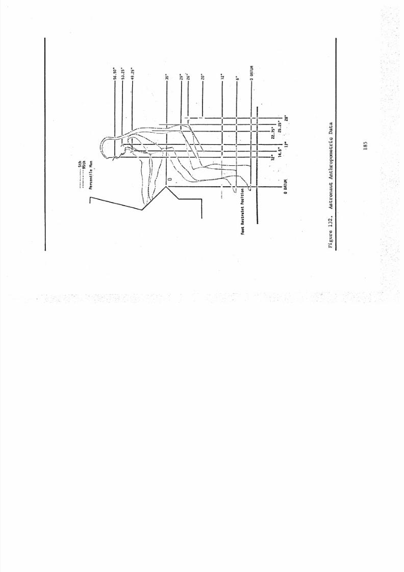
8/8/2019 MSFC Skylab Crew Systems Mission Evaluation
http://slidepdf.com/reader/full/msfc-skylab-crew-systems-mission-evaluation 209/397
c-, I,,-
I <u
, g
N N
• . |"
!+S)/" 'I \ x. +Lf-<..___._---"I \ \, !--lu_
+ *# i,=_ ...+++__--_--\
i +.go
18..
i
O
O
or,,,l
<3
+o
4..3
O
,--I
+. _ +- + + + +, ,+.
8/8/2019 MSFC Skylab Crew Systems Mission Evaluation
http://slidepdf.com/reader/full/msfc-skylab-crew-systems-mission-evaluation 210/397
the data collection and reduction operations and the conclusions that
were drawn from analysis of the data. These data support many of the
conclusions drawn from the subjective evaluations discussed earlierin this report section.
a. Data Collection - The ATM control panel was evaluated
to determine the information that would be required to reconstruct
the panel's operation after the mission. The specific controls and
displays that were used in the operation of the ATM building blocks
were identified, as was the information required to describe their
operation (e.g., switch position). The ATM telemetry measures were
then examined, and the measures that describe the pertinent ATM
controls and displays were identified and requested from the HuntsvilleOperations Support Center (HOSC).
During SL-2, these telemetry data were received on approximately80 magnetic data tapes.
b. Data Reduction - These tapes were processed using adata reduction computer program. This program sorted the data into
files for the seven ATM experiments. It also determined control
actuations and display readings along with the Day of Year and GreenwichMean Time (GMT) when they occurred. This resulted in seven sets of
print-outs, one for each ATM experiment. The print-outs identified
the controls and displays for the experiment, and listed the control'sposition and the display reading as a function of time.
c. Data Analysis/Conclusions - These panel operations were
compared with the operations identified in the building block paneloperating procedures. This comparison resulted in the identification
of operational problem areas and panel design features that contributed
to panel operation deviations. The major findings are:
• The three position toggle switch with three fixed positionshad a deviation rate of 9%*. This indicates that a
visual display such as a mechanical flag or status light
should have been used with this type of switch to preventincorrect settings.
• Experiment modes that had to be manually timed were often
timed incorrectly. Although several multipurpose timers
were available, they were apparently not used all of the
time. A variable timer dedicated to each experiment with
continuous modes of operation (Ha, S052, S055) would have
prevented this problem.
• 25% of the control actuation deviations which occurredwith S082B involved confusion with S082A. In these
cases the S082B experiment was set up and operated
*"Deviation Rate" is defined as the number of deviations which occurred
with a type of control divided by the number of times that type ofcontrol was used. Therefore, this 9% deviation rate means that 9% of
the time the three position toggle switch was used, it was used incor-rectly (e.g., commanded to the wrong position).
186
8/8/2019 MSFC Skylab Crew Systems Mission Evaluation
http://slidepdf.com/reader/full/msfc-skylab-crew-systems-mission-evaluation 211/397
according to the S082A building block procedures. This
probably occurred because the S082A and B controls and
displays were almost identical and had approximately
the same control labeling nomenclature and building
block instructions. These problems could have been
prevented if the experiments had been separated on the
panel, labeled differently (S082 and S084, for instance)
and had different control labeling nomenclature. For
the SL-3 and SL-4 missions, large red and blue decal
letters "A" and "B" were placed on the respective instru-
ments. Also, strips of red and blue tape were added to the
outside experiment boundary to aid in distinguishing one
from the other. The effectiveness of this color coding
in alleviating the confusion caused by the similar appear-
ance of the two experiments will be determined duringSL-3 and SL-4 data reduction.
• Isolated control actuations had a higher deviation rate
(21%) than control actuations that were part of a sequence(2%). Approximately half of these could have been
prevented if an integral timer had been provided for each
experiment that had operating modes requiring manualtiming.
• The panel's left side had a higher deviation rate (6%)
than the right side (2%). This was caused primarily byseveral three position toggle switches on the left side
which were used improperly 9% of the time.
• Building blocks with multiple parts (up to five) separated
by a time allocated for pointing commands had distinctly
different control deviation rates for each part. The
first and last parts had low deviation rates (3% and 7%),
and the central part had a significantly higher deviation
rate (18%) as illustrated in Figure 133. An improvement
could probably have been realized by limiting the number
of building block parts, while increasing the number ofbuilding blocks.
6. Summary and Conclusions - The design of the ATM C&D Console
progressed through numerous design stages. Most significant of these
was the wet to dry workshop change. There were numerous improvementsas a result of program redirection, but there were a considerable
number of problems left uncorrected. One might conclude that these
discrepant design areas have had their impact on accomplishing theoptimum man/machine interface. However, a closer evaluation of the
design job done on this complex scientific system leads one to conclude
that the job was well done. In retrospect, most design engineers who
worked on Skylab would like to modify their past design based on the
knowledge gained from three manned missions. The most cormmon item
187
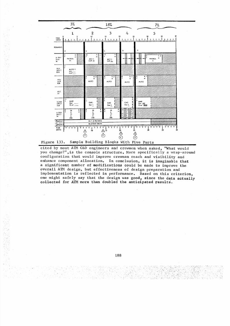
8/8/2019 MSFC Skylab Crew Systems Mission Evaluation
http://slidepdf.com/reader/full/msfc-skylab-crew-systems-mission-evaluation 212/397
,IM[
(BIN)
REMARKS
3%
10 5
18%
2 3 4I0' 15 20
L
7%
530 35 4O
56
×UV
SLII
SCAN
SPECI
X-RAY
_PECI
(MIN) 5 '0 15 _ 2_ _ 35
Figure 133. Sample Building Blocks With Five Parts
cited by most ATM C&D engineers and crewmen when asked, "What would
you change?",is the console structure. More specifically a wrap-around
configuration that would improve crewman reach and visibility and
enhance component allocation. In conclusion, it is imaginable thata significant number of modifications could be made to improve theoverall ATM design, but effectiveness of design preparation and
implementation is reflected in performance. Based on this criterion,
one might safely say that the design was goodp since the data actuallycollected for ATM more than doubled the anticipated _esults.
188
i_:i_ ::!:I!Li:!:_?!i:_i_; :;L
8/8/2019 MSFC Skylab Crew Systems Mission Evaluation
http://slidepdf.com/reader/full/msfc-skylab-crew-systems-mission-evaluation 213/397
APPENDIX A
CREW DEBRIEFING
(Comments on C&D Systems Operation--Summary)
I. The S054 READY/OPERATE light failure required installation ofan auxiliary timer.
2. Displays were extremely stable during vehicle disturbances.
3. Significant oscillation occurred on the roll rate display when
the high rate X 2 switches were used. The crew made attempts
not to use the X 2 switches to avoid the problem.4. Subthreshold flares were not detected on-board.
5. The History Plotter (Be channel) might have given a good curve
indication of postflare activity data if it had not jammed.
6. The S052 READY/OPERATE timing light was 56-sec.(null state delay)instead of 9-sec. per design spec.
7. The SL-2 crew commented that the brightness of the numeric display
on bus 2 (fixed) was not uncomfortable. The integral lighting
was very rarely used, because of the power limitations during
SL-2. Due to this, the crew used only ambient lighting, to whichthey easily adapted.
8. There was considerable ambiguity between gray and white indicatorson the status flags.
9. The similarity between the S082A and S082B instruments did create
some problems in operating differentiation.
i0. Procedure for the XUV Monitor operating INTEGRATE switch was verytiring and complicated.
ii. Several of the systems alert lights remained on during the entire
mission, making detection of a new malfunction/alert visually
impossible.12. The white light coronagraph (S052) instrument required the TV
switch to be cut off prior to closing the doors. The purpose ofthis procedure was to avoid exposing the vidicon to direct sun-light.
13. Performance on-orbit proved to be very similar to performance on
the ATM simulator, and the habits formed during training neverchanged.
14. The ATM cue cards were modified so much that they were hardlyrecognizable.
15. The TV presentation did not provide sufficient detail. The reso-
lution of the on-board TV was not as good as the instrumentsthemselves.
16. A useful tool would have been a lexicon or log to record signifi-
cant ATM comments to update each panel operation on the occurrencesof activities on the sun's disc.
17. The X-ray scope PMC appeared to saturate at a flare utensity of
500 counts rather than the i000 counts for which it was designed.
189
r
8/8/2019 MSFC Skylab Crew Systems Mission Evaluation
http://slidepdf.com/reader/full/msfc-skylab-crew-systems-mission-evaluation 214/397
18. The GRATING SELECT switch was inadvertently left in the MECHANICAL
position when it should have been in the OPTICAL position.
19. The crews commented that experiment setup times improved with
repetition.
20. One crewman stated that the X-ray Be/AI History Plotter design
was ineffective for continued use because of the tendency of thepaper drive unit to hang up.
21. The RNBM was not useful in data analysis because of characteristic
design in band and range sensitivity.
22. The XUV Monitor was a good correlative display for a flare.
23. The H_ display was a good tool for viewing through the building
blocks and pointing and surveying the active regions on the sun.
24. The Ha reticules worked normally.
190
. _ . ,-_""
- . - , , , , , . •
8/8/2019 MSFC Skylab Crew Systems Mission Evaluation
http://slidepdf.com/reader/full/msfc-skylab-crew-systems-mission-evaluation 215/397
SECTION IV. COROLLARY EXPERIMENTS
A. Corollary Experiments Summary
Corollary experiments involved three major categories of experi-
mentation consisting of: scientific, with objectives to acquirephotographic data of solar and stellar phenomena; technological,
with objectives to measure contamination levels surrounding the OA;and operational, with objectives to assess technological innovations
which assisted the crew in performing space related tasks.
Performance of the corollary experiments during Skylab achieved
most of the designed and planned functional objectives. The knowledge
obtained from their operation and the acquired data have provided
insight that will be implemented into the design and operationalrequirements of future manned spacecraft.
The following are some conclusions derived from the on-orbit
corollary experimentation that is applicable to future spacecrafthardware designs and operations.
• An adequate maintenance workstation with appropriate
tools and restraints should be included in future space-craft design.
o Crew manipulation of large experiment equipmentpresents no problems. Multiple, small items were
found to be difficult to constrain and handle. It is
recommended that handles be provisioned on all large
mass items to facilitate their manipulation. Also,
a technique is required to control the manipulation ofmultiple, small items.
Q Of the experiments requiring extension/retraction
through the Scientific Airlock (SAL) into space, it
was found that the retraction forces were somewhathigher as anticipated, and that a warm-up period wasrequired prior to final retraction and removal of
experiments from the SAL to prevent formation ofcondensation/frost.
• Through operations of M509 and TO20, the feasibility
of a one-man maneuvering unit was successfully demonstrated.
• Corollary experiment T013 demonstrated that crew motion
within a large spacecraft does impact its stability andguidance control and therefore, should be considered
in future designs.
This section covers those experiments which were the responsibilityof MSFC or required personnel/hardware support from MSFC.
191
i_ii_
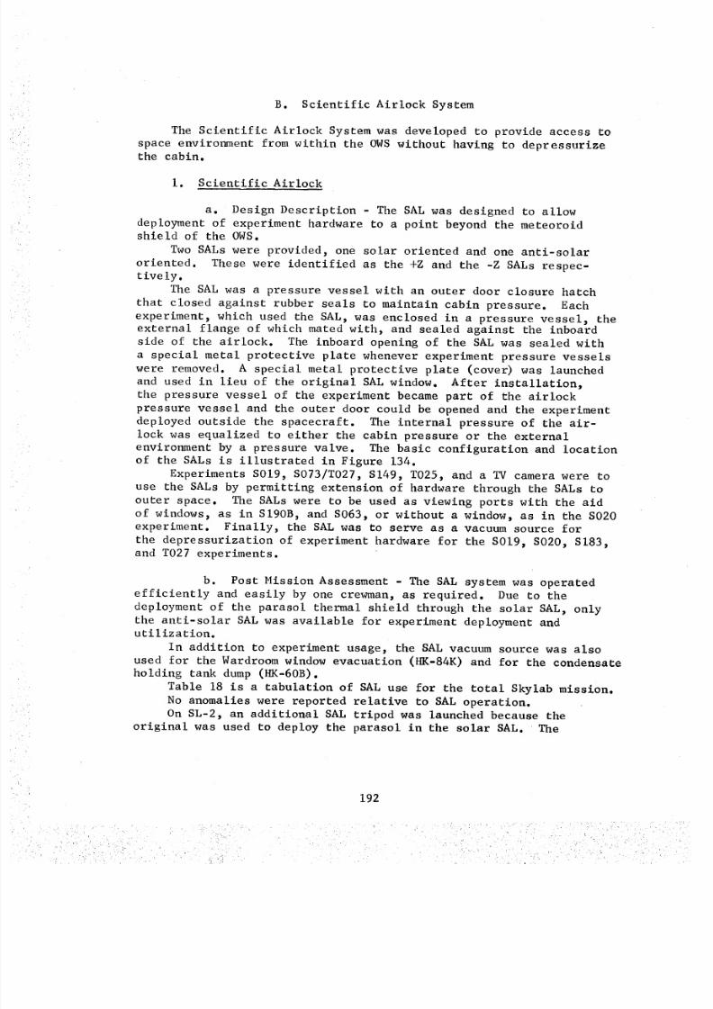
8/8/2019 MSFC Skylab Crew Systems Mission Evaluation
http://slidepdf.com/reader/full/msfc-skylab-crew-systems-mission-evaluation 216/397
B. Scientific Airlock System
The Scientific Airlock System was developed to provide access to
space environment from within the OWS without having to depressurizethe cabin.
I. Scientific Airlock
a. Design Description - The SAL was designed to allow
deployment of experiment hardware to a point beyond the meteoroidshield of the OWS.
Two SALs were provided, one solar oriented and one anti-solar
oriented. These were identified as the +Z and the -Z SALs respec-tively.
The SAL was a pressure vessel with an outer door closure hatch
that closed against rubber seals to maintain cabin pressure. Each
experiment, which used the SAL, was enclosed in a pressure vessel, the
external flange of which mated with, and sealed against the inboardside of the airlock. The inboard opening of the SAL was sealed with
a special metal protective plate whenever experiment pressure vessels
were removed. A special metal protective plate (cover) was launched
and used in lieu of the original SAL window. After installation,the pressure vessel of the experiment became part of the airlock
pressure vessel and the outer door could be opened and the experiment
deployed outside the spacecraft. The internal pressure of the air-
lock was equalized to either the cabin pressure or the externalenvironment by a pressure valve. The basic configuration and location
of the SALs is illustrated in Figure 134.
Experiments S019, S073/T027, S149, T025, and a TV camera were to
use the SALs by permitting extension of hardware through the SALs to
outer space. The SALs were to be used as viewing ports with the aid
of windows, as in SI90B, and S063, or without a window, as in the S020
experiment. Finally, the SAL was to serve as a vacuum source for
the depressurization of experiment hardware for the S019, SO20, S183,and T027 experiments.
b. Post Mission Assessment - The SAL system was operatedefficiently and easily by one crewman, as required. Due to the
deployment of the parasol thermal shield through the solar SAL, only
the anti-solar SAL was available for experiment deployment andutilization.
In addition to experiment usage, the SAL vacuum source was also
used for the Wardroom window evacuation (HK-84K) and for the condensateholding tank dump (HK-60B).
Table 18 is a tabulation of SAL use for the total Skylab mission.
No anomalies were reported relative to SAL operation.
On SL-2, an additional SAL tripod was launched because the
original was used to deploy the parasol in the solar SAL. The
192
r
j
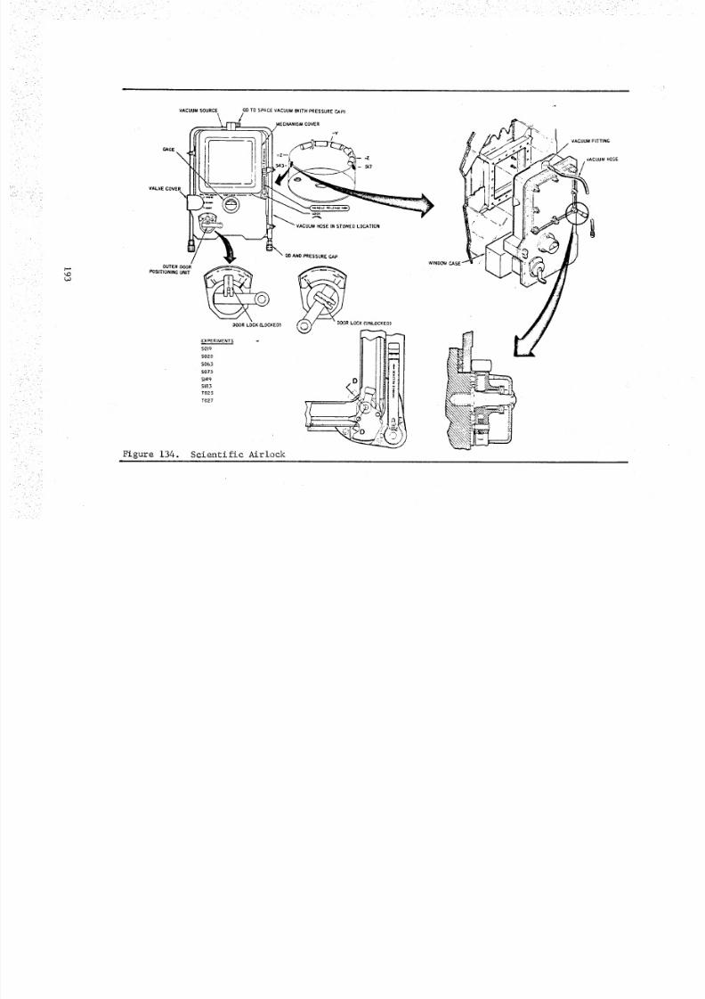
8/8/2019 MSFC Skylab Crew Systems Mission Evaluation
http://slidepdf.com/reader/full/msfc-skylab-crew-systems-mission-evaluation 217/397
.... • ! : • ! •i_• _ii I
{..o
VACUUM SOURCE QO. TO SPACE VACUUM {WITH PRESSURE CAP)
\ /
_ECHANISM COVER _Y
VALVE C OV ER _I
_ -VA=MOSE,NTO_EOO_T,ON
OOOR LOCK ('LOCKED)
EXPERIMENTSSOt9
5020
S063
S073
SI49
SI83
T025
T027
O UT ER D OO RP OS IT IO NI NG U NI T
Figure 134. Scientific Airlock
WINDOW
_RLOCK (UNLOCKED)
VACUUM FITTING
VAC UU M H OS E
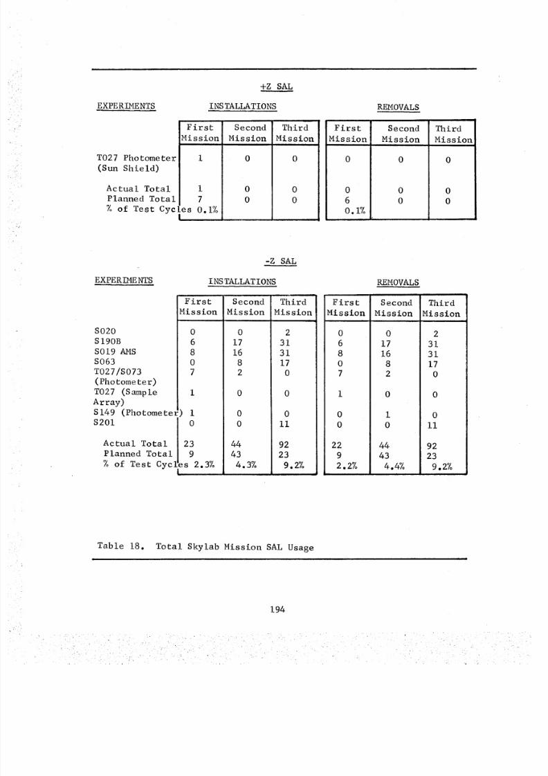
8/8/2019 MSFC Skylab Crew Systems Mission Evaluation
http://slidepdf.com/reader/full/msfc-skylab-crew-systems-mission-evaluation 218/397
EXPERIMENTS
T027 Photometer
(Sun Shield)
+Z SAL
INSTALLATIONS
FirstMission
Actual Total i
Planned Total 7
% of Test C 5 [es 0.1%I
SecondMission
0
0
0
ThirdMission
0
0
0
REMOVALS
FirstMission
0
6
0.1%
SecondMission
0
0
0
ThirdMission
0
0
0
-Z SAL
EXPERIMENTS
S020
SI90B
S019 AMS
S063
T027/S073
(Photometer)T027 (Sample
Array)
S149 (Photomete_
$201
INS TALLATIONS
First
Mission
!) i0
Actual Total 23
Planned Total 9
% of Test Cycles 2.3%;
Second
Mission
0
17
16
82
0
0
44
43
4.3%
im
Third
Mission
2
31
31
17
0
0
ii
92
23
9.2%
REMOVALS
First Second Third
Mission Mission Mission
0
6
8
07
0
17
16
8
2
22
9
2.2%
0
I
0
44
43
4.4%
2
31
31
17
0
0
ii
92
23
9.2%
Table 18. Total Skylab Mission SAL Usage
194
8/8/2019 MSFC Skylab Crew Systems Mission Evaluation
http://slidepdf.com/reader/full/msfc-skylab-crew-systems-mission-evaluation 219/397
backup SAL tripod was used at the antisolar SAL. There was an align-ment problem with the backup tripod at the antisolar SAL which was
solved by anchoring the left leg in its proper location and bolting
the other two legs to the floor grid, after rotating them one or
two grid holes. It was later determined that the backup tripod was
misdrilled, causing a 2-inch offset in the alignment. A check indi-cated that the backup tripod would fit satisfactorily only at the
solar SAL. The flight unit would fit in either SAL position, so the
tripods were exchanged by the second crew. No alignment problemswere encountered during the tripod exchange.
During a condensate dump, one of the crew left the SAL outer door
open and the valve in the "PRESS" position. With the desiccant systemvalve in the "OPEN" position, this allowed cabin air to bleed over-
board, through the desiccant canister, and out of the SAL. The leak
was discovered during the crew sleep period. When the crew woke upthe next day, they were asked to configure the SAL properly. An
analysis was subsequently performed which indicated that the desiccant
system still had at least a 100% margin (5000 grains of H20 ) in spiteof the inadvertant atmosphere dump.
There was not enough illumination to read the SAL delta-P gauge.The crew used a penlight to obtain accurate readings. The black
background and long viewing tube on the delta-P gauge made it difficult
to read. The crew stated the 0-30 psia range on the gauge was
excessive and not necessary. The gauge should have been designed to
facilitate delta-P reading in increments of .025- psia, from 0 to amaximum of 20-psia.
No difficulties were experienced aligning experiments in the SAL
and no flanges or "O"-ring seals were damaged. Experiments placed in
the SAL were adequately supported by the tripod.
The crew reported that the SAL system was tight and never failed
a leak check. Pressurization and depressurization of the SAL requiredmore time than planned. Consequently, this required some lead time to
set up experiments in the SAL. During crew training, actual depres-
surization functions were never performed by the crews. This did not
prepare them with the knowledge of what to expect on-orbit, whenperforming this SAL operation.
195
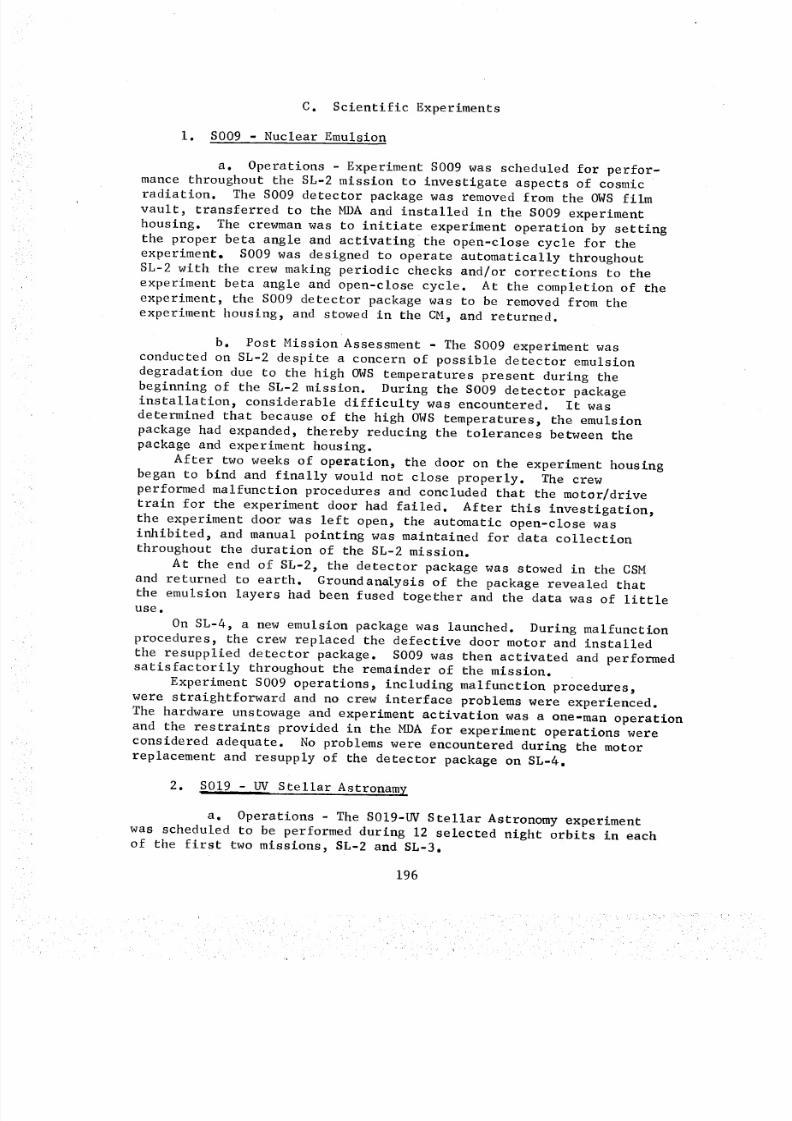
8/8/2019 MSFC Skylab Crew Systems Mission Evaluation
http://slidepdf.com/reader/full/msfc-skylab-crew-systems-mission-evaluation 220/397
C. Scientific Experiments
i. S009 - Nuclear Emulsion
a. Operations - Experiment S009 was scheduled for perfor-
mance throughout the SL-2 mission to investigate aspects of cosmicradiation. The S009 detector package was removed from the OWS film
vault, transferred to the MDA and installed in the S009 experiment
housing. The crewman was to initiate experiment operation by setting
the proper beta angle and activatingthe open-close cycle for the
experiment. S009 was designed to operate automatically throughout
SL-2 with the crew making periodic checks and/or corrections to the
experiment beta angle and open-close cycle. At the completion of the
experiment, the S009 detector package was to be removed from the
experiment housing, and stowed in the CM, and returned.
b. Post MissionAssessment - The S009 experiment was
conducted on SL-2 despite a concern of possible detector emulsion
degradation due to the high OWS temperatures present during the
beginning of the SL-2 mission. During the S009 detector packageinstallation, considerable difficulty was encountered. It was
determined that because of the high OWS temperatures, the emulsionpackage had expanded, thereby reducing the tolerances between the
package and experiment housing.
After two weeks of operation, the door on the experiment housingbegan to bind and finally would not close properly. The crew
performed malfunction procedures and concluded that the motor/drive
train for the experiment door had failed. After this investigation,the experiment door was left open, the automatic open-close was
inhibited, and manual pointing was maintained for data collection
throughout the duration of the SL-2 mission.At the end of SL-2, the detector package was stowed in the CSM
and returned to earth. Groundan_ysis of the package revealed that
the emulsion layers had been fused together and the data was of littleuse,
On SL-4, a new emulsion package was launched. During malfunction
procedures, the crew replaced the defective door motor and installed
the resupplied detector package. S009 was then activated and performedsatisfactorily throughout the remainder of the mission.
Experiment S009 operations, including malfunction procedures,
were straightforward and no crew interface problems were experienced.
The hardware unstowage and experiment activation was a one-man operation
and the restraints provided in the MDA for experiment operations were
considered adequate. No problems were encountered during the motorreplacement and resupply of the detector package on SL-4.
2. SO19 - UV Stellar Astronamy
a. Operations - The SOIg-UV Stellar Astronomy experimentwas scheduled to be performed during 12 selected night orbits in eachof the first two missions, SL-2 and SL-3.
196
8/8/2019 MSFC Skylab Crew Systems Mission Evaluation
http://slidepdf.com/reader/full/msfc-skylab-crew-systems-mission-evaluation 221/397
The equipment consisted of an optical canister and the Articu-lated Mirror System (AMS), launched in individual stowage containers,and film canister, launched in the OWSilm vault. Figure 135illustrates the experiment operating configuration. One crewmanwas to set up and operate _he experiment hardware in the SAL to obtain
a total of 150 slides of data from a minimumof 36 starfields. Threestarfields, with three exposures per starfield, were to be photographedduring each operation. To maximize the scientific data return ofS019, the astronaut was allowed as much flexibility in the choice ofstarfields and exposure times as possible.
b. Post Mission Assessment - During the initial activationof the AMS, a problem occurred in the operation of the tilt mechanism.As a result, this S019operation was aborted and no data was acquired.Through extensive malfunction procedure checkout and finally, disas-sembly of the AMStilt mechanism, the crew discovered an Allen screwbinding on a small gear of the tilt mechanism. This was correctedand the unit functioned properly during the remainder of the experi-ment's data acquisition operations.
During the repair of the AMStilt mechanism, the mirror wasinadvertently touched leaving a finger print on the mirror. At therequest of the Principle Investigator (PI), no corrective procedurewas implemented to removethe print in order to prevent possibleadditional damageto the mirror surface. Attempting to clean themirror mayhave been more degrading to the mirror's viewing functionthan the fingerprint itself.
During SL-3 operations of S019, it was reported that the lumines-cent material had comeout of the engraved digits on one of therotation dials. However, by close inspection, the operator couldstill distinguish the engraved impressions of the digits permittingproper operation of the rotational dial.The S019 spectrometer mechanismjammedduring retraction followingan SL-3 pass. Retraction was eventually accomplished some30-hourssubsequent to the initial failure and normal operations were restored.After the retraction failure, warm-up procedures for all subsequentexperiments placed in the SALwere implemented prior to exposure oftheir mechanismto OWSenvironment.
During an SL-3 S019 pass, the crew reported that the film advance/shutter lever stopped at the "CARRIAGERETRACTED"osition, and couldnot be movedon to the "SLIDERETRACTED"osition. This film canisterwas replaced with the new canister and the remaining exposures weretaken as scheduled during SL-3. The failed canister was taken to anarea of subdued light (the WMC,with lights out and door closed), thecover removed, and the sliding film hatch opened. Inspection, by feel,was performed on part of the carriage and shutter mechanism. The crewcould not identify any apparent damageor discrepancy that could becorrected. Consequently, the film canister unit was returned to earthfor malfunction analysis.
It was found, from the review of acquired data, that during per-formance of the S019 experiment, the system was extremely sensitive tomotion and someblurs occurred on one S019 slide. It was felt that
197
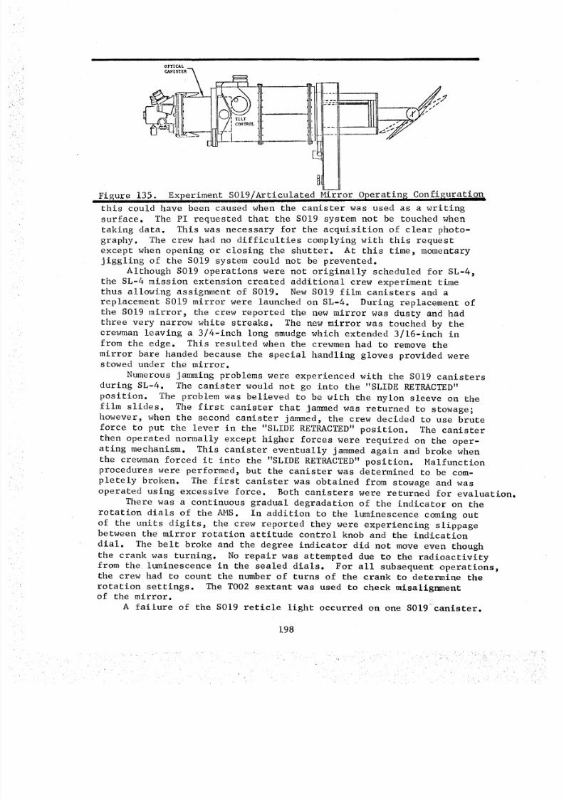
8/8/2019 MSFC Skylab Crew Systems Mission Evaluation
http://slidepdf.com/reader/full/msfc-skylab-crew-systems-mission-evaluation 222/397
OPTICAL
I T I L'i"
I_--. I CONTROL ' +
Figure 135. Experiment S019/Articulated Mirror Operatin$ ConfiguratiQ_
this could have been caused when the canister was used as a writing
surface. The PI requested that the S019 system not be touched when
taking data. This was necessary for the acquisition of clear photo-
graphy. The crew had no difficulties complying with this request
except when opening or closing the shutter. At this time, momentary
jiggling of the S019 system could not be prevented.Although S019 operations were not originally scheduled for SL-4,
the SL-4 mission extension created additional crew experiment time
thus allowing assignment of S019. New S019 film canisters and a
replacement S019 mirror were launched on SL-4. During replacement of
the S019 mirror, the crew reported the new mirror was dusty and had
three very narrow white streaks. The new mirror was touched by thecrewman leaving a 3/4-inch long smudge which extended 3/16-inch in
from the edge. This resulted when the crewmen had to remove the
mirror bare handed because the special handling gloves provided werestowed under the mirror.
Numerous jamming problems were experienced with the S019 canisters
during SL-4. The canister would not go into the "SLIDE RETRACTED"
position. The problem was believed to be with the nylon sleeve on the
film slides. The first canister that jammed was returned to stowage;however, when the second canister jammed, the crew decided to use brute
force to put the lever in the "SLIDE RETRACTED" position. The canister
then operated normally except higher forces were required on the oper-
ating mechanism. This canister eventually jammed again and broke when
the crewman forced it into the "SLIDE RETRACTED" position. Malfunctionprocedures were performed, but the canister was determined to be com-
pletely broken. The first canister was obtained from stowage and was
operated using excessive force. Both canisters were returned for evaluation.
There was a continuous gradual degradation of the indicator on the
rotation dials of the AMS. In addition to the luminescence coming out
of the units digits, the crew reported they were experiencing slippagebetween the mirror rotation attitude control knob and the indication
dial. The belt broke and the degree indicator did not move even though
the crank was turning. No repair was attempted due to the radioactivity
from the luminescence in the sealed dials. For all subsequent operations,the crew had to count the number of turns of the crank to determine the
rotation settings. The TO02 sextant was used to check misalignmentof the mirror.
A failure of the S019 reticle light occurred on one S019 canister.
198
8/8/2019 MSFC Skylab Crew Systems Mission Evaluation
http://slidepdf.com/reader/full/msfc-skylab-crew-systems-mission-evaluation 223/397
The crew reported earlier that the reticle light was dim and assumedthat the battery charge was too low to illuminate the bulb. The bulband battery were not replaceable, but the reticle was for "referenceonly" and no data was lost due to the failure. No corrective actionwas necessary, however, the crew turned off the reticle light when itwas not required to verify pointing accuracy.
An additional S019 operation requirement was imposed during SL-4to reduce possible data degradation due to OWSnfluenced disturbanceson the pointing accuracy. During SL-4, all ergometer and Mark Iexerciser operations were prohibited during S019 operations.
The crew recommendedhat the first couple of S019 pads be relative-ly easy to give them a chance to re-familiarize themselves with theexperiment's operations. The crew felt that 80%of all crew errorswould probably occur during the first runs of the experiment. Theyalso stated that S019 procedures needed to be updated with more exactinformation concerning photography exposure times.
Differences existed between the forces required to operate thecontrols of the different S019 canisters. Somecanisters' carriage
retract systems operated easily, while others were quite stiff. ThePI stated that this was normal as they were not all the same. Theoperating controls should have been designed with appropriate "STOP"positions to eliminate tile necessity of counting crank turns to the"FULLEXTENDED"f "FULLRETRACTED"ositions. The crew also recommend-ed that the locks on the shaft rotation or extension controls not beused, as they were no longer required after placing the control in the"UNLOCKED"osition.
The S019 timelines were too close; therefore, the crew recommendedthat 30-seconds to one-minute be allocated for the operator to performa change in pointing. They also suggested adding 15 to 30-minutes tothe timeline, for the first running of the experiment, to allow forfamiliarization with the equipment.
The crew requested that the samecrewmannot be assigned to an ATMpass and an S019 pass with no time in between because any delays in theATMpass immediately affected the S019 operations.
The crew suggested having a T-handle on top of the winding valveinstead of the knob. The knob was very slippery when their hands weremoist and a T-handle would have been better for winding the film.
Experiment handling was easy on-orbit comparedto ground handling.The crew said that the carrying handle for the optical canister wasa necessity.
The procedures for changing the viewing coordinates were very sat-isfactory, but there was a definite source of potential error with thesign and algebraic manipulations required to compute the rotation. Thecrew had not trained for these calculations and thought that they should
have had training to becomefamiliar with the calculations.There were no problems with dark adaptation when operating S019.The critical requirements to prevent dark adaptation problems werethe position of the eye with respect to the eye piece and the focus.
The repair work performed on the AMStilt mechanismwould havebeen aided by the addition of an Inflight Maintenance facility composedof a work bench and a high intensity light. An optics cleaning kitwould have been valuable to remove the finger print contaminationfrom the AMSmirror and should be provided on future flights.
199
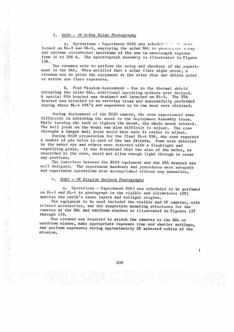
8/8/2019 MSFC Skylab Crew Systems Mission Evaluation
http://slidepdf.com/reader/full/msfc-skylab-crew-systems-mission-evaluation 224/397
3. S020 - UV X-Ray Solar Photography
a. Operations - Experiment S020 was schedul, _,I_ !_, per-
formed on SL-3 and SL-4, employing the solar SAL to photogl_l_h x-ray
and extreme ultraviolet spectrums of the sun in wavelength regionsfrom i0 to 200 A. The spectrograph assembly is illustrated in Figure136.
Two crewmen were to perform the setup and checkout of the experi-
ment in the SAL. When notified that a solar flare might occur, a
crewman was to point the equipment at the solar disc and obtain quiet
or active sun flare exposures.
b. Post Mission Assessment - Due to the thermal shield
occupying the solar SAL, additional operating methods were devised.A special EVA bracket was designed and launched on SL-3. The EVA
bracket was attached to an exterior truss and successfully performedduring three SL-4 EVA's and exposures up to one hour were obtained.
During deployment of the S020 camera, the crew experienced some
difficulty in attaching the mount to the Deployment Assembly truss.
While turning the knob to tighten the mount, the whole mount twisted.
The ball joint on the mount was also difficult to adjust. The crew
throught a larger ball joint would have made it easier to adjust.
During S020 preparation for the final SL-4 EVA, the crew reporteda number of pin holes in each of the two filters. Some were detected
by the maked eye and others were detected with a flashlight and
magnifying glass. It was determined that the size of the holes, asdescribed by the crew, would not allow enough light through to cause
any problems.
The interface between the S020 equipment and the EVA bracket was
well designed. The experiment hardware and procedures were adequate
and experiment operations were accomplished without any anomalies.
4. S063 - UV Airglow Horizon Photography
a. Operations - Experiment S063 was scheduled to be perfomedon SL-3 and SL-4 to photograph in the visible and ultraviolet (UV)
spectra the earth's ozone layers and twilight airglow.
The equipment to be used included the visible and UV cameras, withrelated accessories, and the respective mounting structures for the
cameras at the SAL and wardroom windows as illustrated in Figures 137through 139.
One crewman was required to attach the cameras to the SAL or
wardroom window, make appropriate exposure time and shutter settings,and perform exposures during approximately 28 selected orbits of themission.
200
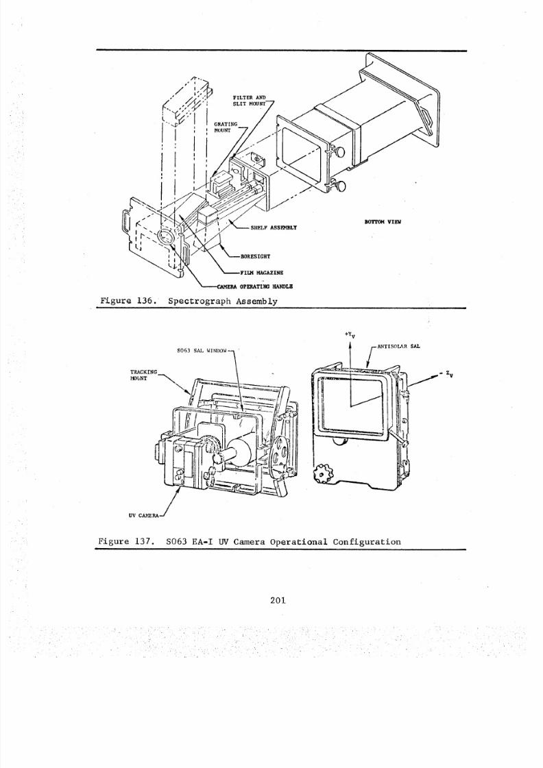
8/8/2019 MSFC Skylab Crew Systems Mission Evaluation
http://slidepdf.com/reader/full/msfc-skylab-crew-systems-mission-evaluation 225/397
Figure 136
ASSF/4BLY
F ILH M AGA ZINE
oP_T_ _LK
Spectrograph Assembly
BOTTOH VIEW
+¥,
S063 SAL WINDOW_" _----__-/ANTISOLAR SAL
_=_= ___, ..-ZvI /I1
//
UV CAME RA-._
Figure 137. S063 EA-I UV Camera Operational Configuration
201
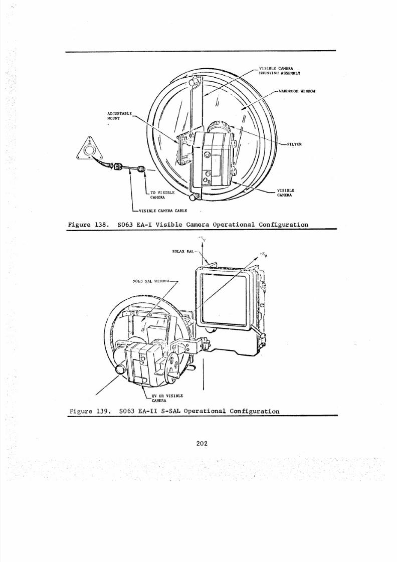
8/8/2019 MSFC Skylab Crew Systems Mission Evaluation
http://slidepdf.com/reader/full/msfc-skylab-crew-systems-mission-evaluation 226/397
ADJUSTABLE
MOUNT
VISIBLE CAMERA
HOUNT [ NC, ASSEMBLY
_ WARI)ROOH WINDOW
TER
•Figure 138.
VISIBLE VISIBLE
C_RA CAMERA
VISIBLE CAMERA CABLE
S063 EA-I Visible Camera Operational Configuration
It V
S063 SAL
SOLAR SAI,--\
UVOR VISIBLE
CAmeRA
+Z v
Figure 139. S063 EA-II S-SAL Operational Configuration
202
8/8/2019 MSFC Skylab Crew Systems Mission Evaluation
http://slidepdf.com/reader/full/msfc-skylab-crew-systems-mission-evaluation 227/397
b. Post Mission Assessment - Some difficulty was experienced
during the loading of a new Nikon camera for S063 operations. Upon
investigation it was found that a bit of epoxy-like material prevented
the film system from positioning properly. The crew removed this
material with a knife and the camera operated satisfactorily for the
remainder of the mission.Due to solar SAL obstructions by the thermal shield, the S019
AMS was utilized to obtain some of the S063 data.
During initial operations, there was a problem as a result of a
timer malfunction. Analysis established that the motor drive switch
was not in the correct configuration and that the timer was beingoperated incorrectly. This problem required that the crewmen use
their wristwatch in conjunction with the timer for all subsequent 8063operations.
The crewman had to use a flashlight to read the watch and timer.
The crew requested an additional 45-seconds preparation time betweenexposures. At the request of the crew, information on how to inter-
pret the S063 optical sight reticle was provided by the ground.
Due to a problem encountered in setting the viewing equipment,
some exposures may have been lO-second exposures rather than the
scheduled 8-second exposures. The marker on the viewing equipment hada bright edge and light glinted off the leading edge of the marker
through the window. The viewing equipment was set on this leading
edge rather than the white alignment mark, thereby adding approximatelytwo-seconds to each exposure.
One visible photography portion of an S063 run was not obtained
because a battery, powering the visible camera, had tape covering one
terminal. This tape was removed and no further problems were encount-ered.
During SL-3, it was noted that an adapter between the AMS and the
S063 window was missing a bolt. This missing bolt did not affectexperiment operations, but a replacement bolt was provided for SL-4.
The crew also reported tightening the mounting shear to the opticalsight of the camera with tape, thereby providing better resolution.
During the initial SL-4 S063 operation, the remote timer did not
operate. This complicated the experiment operation because the crewman
had to use manual timing, in addition to tracking and controlling the
rotation and tilt settings. The timer did not operate because the
crew mistakenly used a timer without any batteries. A new batterywas installed in the remote timer and solved the problem. For sub-
sequent operations, the crew removed the batteries after each use and
taped them to the timer to prevent discharge of the batteries.
The crew reported the ring site was aligned in the wrong direction
and that it should be aligned more towards the camera axis. Part of
the sight was obscured such that the crewmen could not see the whole
mirror. The crewman assumed that although his view was truncated, the
camera was getting the full view. He therefore centered the sight in
203
8/8/2019 MSFC Skylab Crew Systems Mission Evaluation
http://slidepdf.com/reader/full/msfc-skylab-crew-systems-mission-evaluation 228/397
the circle and not in the truncated portion of the field of view.
The crewman found that, by looking right below everything, straight
at the AMS mirror, he could get a better field of view than looking
through the sights.
A problem was experienced with the S063 reticle light when it
failed to illuminate. The crew checked the prime and backup batteries
and found they had an output of 1.6-volts compared to 3.l-volts pre-
flight. The battery contacts were scraped clean, but neither battery
would illuminate the reticle light. A substitute battery pack wasfabricated from two spare "C" cells, tape, and two multimeter leads.
The substitute battery pack was installed by inserting the probe ends
of the leads into the female terminals of the optical sight housing.Normal reticle operation was then restored.
The S063 stowage and unstowage operations were accomplished as
planned. In some instances, the crew had to hurry to get two photo-graphs on the same target, but the tracking task time allocation was
adequate. The time allocated for stowage and preparation of S063and AMS equipment was also adequate.
The stowage location of the twin filter underneath the S063
stowage container lid was inadequate because of poor lighting and
visibility in that area. This inadequacy was identified in trainingbut never corrected.
The crew stated that they should have had one extra Nikon camera
body and a minimum of six extra cassettes of 2485 fast film for photo-
graphy of targets of opportunity. A great opportunity to properly
photograph the Aurora, may have been missed, because these items were
not on board. The crew recommended replacing the Hasselblad in theCM with a Nikon.
The crew recommended that some type of suction-cup mount be
supplied for cameras used in hand-held photography. These cameras
could then be restrained at any window. Such a restraint should belight, have a shutter release, and designed so that it could be moved
to any position.
The crew recommended that the PI provide a small color chart
identifying the different shades of night airglow gray or white as theymay appear to the crew. This would make identification easier for the
crew and provide a commonality point between ground and on-orbit data.
Crew training for S063 appeared to be inadequate because the
timer was operated incorrectly and the crew had to request informationon how to interpret the reticle.
The SL-4 crew stressed that, due to the lack of an S063 simulator,the first couple of experiment runs would have to be considered train-
ing sessions. Any operations that called for manual dexterity by thecrewman could not be learned by oral communications. The crew stated
they had more difficulty with S063 than with other more complicated
experiments which they had trained for. Even a relatively simpletask requires a couple of familiarization runs.
204
8/8/2019 MSFC Skylab Crew Systems Mission Evaluation
http://slidepdf.com/reader/full/msfc-skylab-crew-systems-mission-evaluation 229/397
There was some confusion in determining the frame count on the
UV Nikon camera. The frame count on the top of the Nikon read
differently than the frame count on the bottom of the camera. The crewdecided to use only the bottom frame count indicator. There should
be only one frame count indicator per camera.
5. S073/T027 - Gegenschein Zodiacal Light and ATM ContaminationMeasurement
a. Operations - Experiment S073/T027 was scheduled for
operation during SL-2 and SL-3. The purpose of S073 was to measure
surface brightness and polarization of night glow in visible spectrum.
The purpose of T027 was to determine changes in properties of optical
samples due to deposition of contaminates and to measure sky bright-ness background due to solar illumination of contaminates.
The experiment employed the T027 Photometer Canister with the
automatic programmer. The combined photometer system and DataAcquisition Camera (DAC) system, which was attached to the T027
Universal Extension Mechanism (UXM), was mounted to and deployedthrough the SAL into the space environment for acquisition of data.
S073/T027 was designed for operation by one crewman.
b. Post Mission Assessment - During SL-2, the S073/T027
photometer system was activated and operated with no major difficulties.
During one T027 retraction, the photometer system could not be lined
up properly to allow its retraction into the SAL and the T027 canister.
This was a T027 systems operations problem. The system had been
driven past the desired alignment. The photometer system was bumped
against the OWS and physically forced into alignment. This corrected
the problem and the system was retracted into the SAL and T027 canister.
During SL-3, the first crew operation with the T027 UXM systemwas to retract the S149 system, which had been left extended throughthe SAL during the unmanned period between SL-2 and SL-3. This was
accomplished with some difficulty. The final extension rod stoppedabout one-inch from full retraction and prevented engagement of the
UXM capture latch. To solve the problem the SAL door was closed to
permit the system to warm up. After warming, the final retraction waseasily accomplished.
The SL-3 crew performed the T027 photometer extension and data
gathering successfully, but during the retraction mode, it failed to
align to the required position to permit its retraction. This had
previously occurred during the SL-2 mission. All malfunction operations
performed failed to allow its retraction. Consequently, the U_XM, with
the photometer and S073 system attached, was jettisoned on MD-8 ofSL-3.
The SL-3 and SL-4 crews utilized the T025 hardware to perform
some S073 Gegenschein and Zodiacal light photography. The equipment
was installed upside-down in the anti-solar SAL and the occulting disc
2O5
8/8/2019 MSFC Skylab Crew Systems Mission Evaluation
http://slidepdf.com/reader/full/msfc-skylab-crew-systems-mission-evaluation 230/397
was moved out of the cameras view. No anomalies were reported withthis mode of operation.
Experiment T027 handling was a one-man operation and was facili-
tated by the canister handle's proper location through the center of
gravity. On movable items of large volume and mass (i.e. T027,
S183) handles are definitely required. The handle(s) should be
located such that the crewman had complete control of the objectduring maneuvering operations.
No problems were encountered during photometer head changeout
and maintenance, despite the compressed operational envelope caused
by the parasol canister/tripod protrusion. Instead of restowing
T027 in its launch container between operations, the crews left the
photometer attached to the launch container lid.
As T027 operations progressed, the crews noticed that the photo-meter UXM rods became increasingly difficult to screw together. This
was thought to be caused by a buildup of moisture and contamination.
Also, during rod retraction, the crews reported that the thermal
gloves were required but did not hinder the crewman's rod retractionoperations. The SL-3 crew indicated that the T027 system should have
been checked out completely and possibly operated inside the OWSprior to its use.
6. S149 - Particle Collection
A. Operations - Experiment S149 was scheduled for performance
in four different exposure periods; during SL-2, the unmanned periodbetween SL-2 and SL-3, during SL-3, and the unmanned period between
SL-3 and SL-4. Its design objective was to acquire data to assist
in the determination of mass distribution of micrometeorites in near-earth space.
The S149 Motor Drive/Cassette Support Unit (MD/CSU) was to be
unstowed, fitted with the detector cassettes, and attached to the
T027 Photometer Universal Extension Mechanism (UXM). The T027 canis-
ter was designed to be installed in the anti-solar SAL and the S149
MD/CSU extended into space. Figure 140 illustrates the experiment
operational configuration. Power was to be applied to the experiment
and switches configured for ground activation of cassette exposure.
In the event of a ground command failure, the experiment had a manual
control capability which could be operated by the crew.
At completion of the exposure time, the crew was to retract,remove, and stow the hardware.
b. Post Mission Assessment - During SL-2, the first of foursets of S149 detector cassettes was deployed through the anti-solar
SAL. Prior to crew return to earth, ground commanded the MC/CSU to
"OPEN" for cassette exposure and subsequent data collection betweenmissions.
206
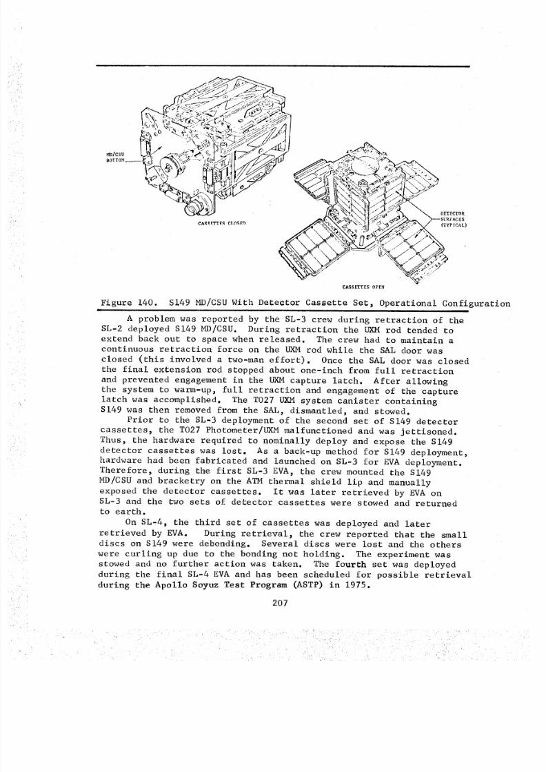
8/8/2019 MSFC Skylab Crew Systems Mission Evaluation
http://slidepdf.com/reader/full/msfc-skylab-crew-systems-mission-evaluation 231/397
CASSETTES OPEN
Figure 140. S149 MD/CSU With De_ector Cassette Set, Operational Configuration|
A problem was reported by the SL-3 crew during retraction of the
SL-2 deployed S149 MD/CSU. During retraction the UXM rod tended to
extend back out to space when released. The crew had to maintain a
continuous retraction force on the UXM rod while the SAL door was
closed (this involved a two-man effort). Once the SAL door was closed
the final extension rod stopped about one-inch from full retraction
and prevented engagement in the UXM capture latch. After allowingthe system to warm-up, full retraction and engagement of the capture
latch was accomplished. The T027 UXM system canister containingS149 was then removed from the SAL, dismantled, and stowed.
Prior to the SL-3 deployment of the second set of S149 detector
cassettes, the T027 Photometer/UXM malfunctioned and was jettisoned.
Thus, the hardware required to nominally deploy and expose the S149
detector cassettes was lost. As a back-up method for S149 deployment,
hardware had been fabricated and launched on SL-3 for EVA deployment.Therefore, during the first SL-3 EVA, the crew mounted the S149
MD/CSU and bracketry on the ATM thermal shield lip and manually
exposed the detector cassettes. It was later retrieved by EVA onSL-3 and the two sets of detector cassettes were stowed and returned
to earth.
On SL-4, the third set of cassettes was deployed and later
retrieved by EVA. During retrieval, the crew reported that the small
discs on S149 were debonding. Several discs were lost and the others
were curling up due to the bonding not holding. The experiment was
stowed and no further action was taken. The fourth set was deployed
during the final SL-4 EVA and has been scheduled for possible retrieval
during the Apollo Soyuz Test Program (ASTP) in 1975.
207
8/8/2019 MSFC Skylab Crew Systems Mission Evaluation
http://slidepdf.com/reader/full/msfc-skylab-crew-systems-mission-evaluation 232/397
S149 hardware, for both nominal and contingency operations, was
well designed and operated as planned. The contingency hardware,used in EVA deployment of S149, functioned well. The bracket used
in mounting the MD/CSU on the ATM thermal shield was a little loose
but caused no problems. The ATM thermal shield paint was scratchedas the mounting clamp was attached but this was not considered to be
detrimental.
7. S183 - Ultraviolet Panorama
a. Operations - Experiment S183 was scheduled during eachof the Skylab missions to obtain photographs of a wide field of view
of individual stars and extended star fields in the ultraviolet.
Prior to activation of S183, the crewman was to prepare the S183
support hardware, the SAL and the S019 AMS. Once the SAL was prepared,
the S019 AMS_ used for S183 pointing, was to be inserted. The S183
experiment was to be unstowed and attached to the S019 AMS. The
S183 film carrousel was then to be removed from the OWS film vaultand installed into S183 along with a 16mm Data Acquisition Camera
(DAC) to provide comparison photographic data. The crewman then was
to power-up S183, open the SAL door and extended the AMS mirror.
The S019 AMS mirror was to be aligned to the desired starfield and
S183 photography was to commence as outlined by the checklist. Once
this photographic sequence had been completed, the S183 experiment wasto be deactivated, the S019 AMS retracted and the SAL closed. The
experiment hardware was to be dismantled, removed from the SAL, andstowed.
b. Post Mission Assessment - Crew comments and other data
related to on-orbit operations of S183 identified problems of a
mechanical operational nature. After two nominal SL-2 performances,the film plate jammed and the operations were discontinued. Malfunction
procedures were performed and the problem was isolated to the film
carrousel. Due to this problem, all subsequent photographic data forthe SL-2 and SL-3 performances was obtained by the use of the 16mm
DAC. One other anomaly was reported and involved a focus problemwith the 16mm DAC. Changing to another DAC did not alleviate the
problem but indicated that the S183 DAC optic system was the problem.
On SL-4, a replacement DAC optic system was launched, interchanged
with the original, and the focus problem corrected. In conjunctionwith the optics replacement, the crew performed additional malfunction
procedures and were successful in correcting the film carrousel
anomaly. This permitted the experiment to be operated throughout the
mission to acquire S183 photographic data as originally planned.
Upon removal of the carrousel from the spectrograph during the
second S183 operation on SL-4, a fragment of the SC-5 glass film platewas discovered. It was reported that the carrousel was misaligned
45 ° from the "00" position. A plate was protruding and the crewman
208
8/8/2019 MSFC Skylab Crew Systems Mission Evaluation
http://slidepdf.com/reader/full/msfc-skylab-crew-systems-mission-evaluation 233/397
pushed it into the carrousel and stowed the carrousel. Prior to the
next operation, an alignment procedure was performed and no problemsor loose glass fragments were reported. Pliers were used to rotate
the carrousel 45 ° to the "00" position. During the fourth operation
of the spectrograph, an additional fragment of the SC-5 plate was
discovered. It was concluded that the glass was jamming the carrousel.A malfunction procedure to remove the plate was unsuccessful. In
addition, an "E" clip retaining a spring used to force the carrousel
into the indexing detents was lost. This did not eliminate the use
of the carrousel but it did require that the crewman check the orienta-
tion marks prior to each use. Extreme care had to be used when insert-
ing the carrousel into the spectrograph. Any sudden torquing around
the cyclindrical axis would misalign the unit, thus causing difficult,if not impossible, installation.
Sequence problems with the logic counter and the carrousel
index, due to hardware problems and procedural errors, were experi-enced. The SL-3 crew had failed to reset the logic counter and the
SL-4 crew cycled the plate advance reset switch and returned the
reading to 01. However, the logic counter is completely independent
of the carrousel indexing, and the film carrousel rotated to plate
33 and not back to plate i. This caused plate 34 to become detached
from the carrousel and exposed to cabin light. The result of the
anomaly appeared to be the loss of one plate and degradation of two
others. The operation of S183 spectrograph and film carrousel was
not affected. In an effort to eliminate the condition which caused
the film plate to slip out of place, a malfunction/synchronization
procedure, to synchronize the carrousel with the logic counter, wasperformed.
The crew also experienced a jamming problem with the DAC camera
and S183 magazine 04. After performing trouble shooting procedures,
the problem was isolated to a blown fuse inside the S183 spectro-graph assembly. The malfunction was duplicated on the quality testunit in France and the experiment developer recommended a work-
around procedure which would bypass the blown fuse by connecting an
existing wire from a DAC connector on the spectrograph assembly to an
adjacent connector. The procedure was successful and S183 operationswith the carrousel were resumed.
The S183 experiment activation and manipulation was easily a
one-man operation. The latching technique and decals on the experimentlaunch stowage structure were adequate. The crew stated that for
maneuvering the large mass of S183, the handholds supplied were a
definite necessity. In addition, the crew recommended that on large
masses (i.e. S183, T027) it would be best to have handles provided to
facilitate two-handed manipulation for better control during largemass handling/maneuvering. The maneuvering technique used was for the
crewman to stabilize his body, carefully push the mass in front of him-
self and then let the mass and himself move to the terminal location,making positional corrections while in flight. Braking was not consi-
dered a problem. This maneuvering technique was documented by experi-ment MI51, Time and Motion Study.
209
8/8/2019 MSFC Skylab Crew Systems Mission Evaluation
http://slidepdf.com/reader/full/msfc-skylab-crew-systems-mission-evaluation 234/397
The S183 operations timeline did not allow enough time between
exposures. One-minute was added to these times to allow the crew
to adjust pointing and timing for the upcoming exposure. The crew
also complained about being rushed between an ATM pass and S183
operations. The timeline did not allow ample time to debrief the ATM
pass and commence S183 operations. The crew reported no problems
associated with the OWS lighting levels during S183 operations.
8. $201 - Electronographic Camera
a. Operations - Experiment $201 was performed on SL-4 to
photographically collect Extreme Ultraviolet (XUV) imagery data onComet Kohoutek.
The experiment consisted of a canister-enclosed XUV electrono-
graphic camera (with film-transport box), a second film-transport
box, and an EVA bracket. The experiment was used in two operatingconfigurations; (i) through the anti-solar SAL utilizing the S019 AMS
as support equipment and (2) bracket-mounted to the ATM truss for EVAoperations. Power was provided by the DAC cable during the EVA and
SAL operations. Experiment $201 data was recorded on special NTB-3film.
b. Post Mission Assessment - While performing an $201
experiment operation through the anti-solar SAL, the crew noted that
the green exposure sequence indicator light was actually brownish red
and very low in brightness and as a result, would probably be difficult
to read during the EVA operations. During the second SL-4 EVA, three
$201 data takes were performed even though the crew could not see the
comet. It was hoped that the comet would be detectable on the photo-graphic data.
Experiment $201 operations were performed as scheduled. The
procedures and equipment were adequate and the crew reported no signifi-cant problems.
9. $228 - Trans - Uranic Cosmic Rays
a. Operations - Experiment $228 was scheduled for perfor-mance on SL-2, SL-3, and SL-4 to obtain knowledge of the abundance of
nuclei with an atomic number greater than 26 in the cosmic radiation.
One SL-2 crewman was to deploy the detector module harness, from
floor to ceiling, in the OWS experiment compartment using velcro straps
as illustrated in Figure 141. Thirty-six detector modules were
launched to be deployed with the harness. At the conclusion of theSL-3 mission, one module was to be removed and returned. One $228
detector module was to be launched on SL-4 and deployed during thefirst SL-4 EVA. It was to be retrieved during the last SL-4 EVA and
returned to earth along with the remaining harness detector modules.
210
•• • / •i:: :i• /L_ •_: / • ....
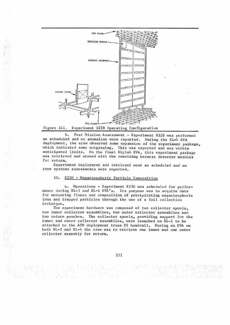
8/8/2019 MSFC Skylab Crew Systems Mission Evaluation
http://slidepdf.com/reader/full/msfc-skylab-crew-systems-mission-evaluation 235/397
DETECTOR MODULE % , i
_SS AS S E't_B Ly.-....__
V---]
Figure 141. Experiment $228 Operating Configuration|i
b. Post Mission Assessment - Experiment $228 was perfomed
as scheduled and no anomalies were reported. During the SL-4 EVA
deployment, the crew observed some expansion of the experiment package,which indicated some outgassing. This was expected and was within
anticipated limits. On the final Skylab EVA, this experiment packagewas retrieved and stowed with the remaining harness detector modules
for return.Experiment deployment and retrieval went as scheduled and no
crew systems assessments were reported.
i0. $230 - Magnetospheric Particle Composition
a. Operations - Experiment $230 was scheduled for perfor-mance during SL-3 and SL-4 EVA's. Its purpose was to acquire data
for measuring fluxes and composition of precipitating magnetospheric
ions and trapped particles through the use of a foil collection
technique.
The experiment hardware was composed of two collector spools,
two inner collector assemblies, two outer collector assemblies and
two return pouches. The collector spools, providing support for the
inner and outer collector assemblies_ were launched on SL-I to be
attached to the ATM deployment truss D2 handrail. During an EVA onboth SL-3 and SL-4 the crew was to retrieve one inner and one outer
collector assembly for return.
211
8/8/2019 MSFC Skylab Crew Systems Mission Evaluation
http://slidepdf.com/reader/full/msfc-skylab-crew-systems-mission-evaluation 236/397
b. Post Mission Assessment - On the first SL-3 EVA, thetwo outer collector assemblies were retrieved and a calibration shieldwas installed on the forward inner collector spool. During the finalSL-3 EVA, the crew retrieved one of the two remaining inner collectorassemblies.
On SL-4, a new inner collector assembly was launched and, onthe first SL-4 EVA, attached to the empty collector spool. During asubsequent EVAfor ATMfilm resupply and Kouhotek photography, thecrew reported that the $230 calibration shield was missing. Evidently,the shield had been brushed and knocked loose by one of the crewduring EVAoperations. On the final SL-4 EVA, the remaining two innercollector assemblies were retrieved for return. During AMrepressuri-zation operations, one of the two samples was damagedby air fromequalization valve 311. The crew reported the damageto effectapproximately 10%of the sample.
The EVAprocedures for the collector assembly retrievals werestraightforward and no problems were reported. The crew reported
that they were very careful during retrieval so as not to touch, andconsequently contaminate, the collectors.The calibration shield and the one collector assembly deployment
were performed without any reported crew interface problems. Therestraint/stability provisions were considered adequate for performingthe $230 crew tasks.
ii. $232 - Barium Plasma Observations
a. Operations - Experiment $232 was scheduled to be per-formed on SL-4 to obtain data necessary for determining the effects
of plasma conductivity and geomagnetic activity upon the motion ofbarium plasma.
The experiment operations involved one crewman whose objectives
were to photograph the barium cloud injected to outer space by a
ground launched rocket. The crewman was notified three hours prior
to the scheduled launch as to the photographic settings and proce-dures. A Nikon 35mm camera was attached to the universal mount and
then mounted to the OWS wardroom window to obtain the photographic
data. A total of seven barium rocket launches were scheduled during
SL-4 with the crewman obtaining a minimum of 40 photographs.
b. Post Mission Assessment - Experiment $232 was performedas planned. Due to problems involved with the rocket launches and
resulting launch cancellations, all premission planned photographic
data was not obtained. The crew reported that the experiment set-upwas a lengthy operation and took approximately two hours to complete.
The barium injection was visible to the naked eye and was photographed
by the crew using _lumerous time exposures. During these photographic
sessions, the crew reported some difficulties with damping the oscilla-
tions of the camera/universal mount after exposure actuation. As the
experiment progressed and the crew technique improved, these oscilla-tions were reduced.
212
8/8/2019 MSFC Skylab Crew Systems Mission Evaluation
http://slidepdf.com/reader/full/msfc-skylab-crew-systems-mission-evaluation 237/397
12. $233K - Kohoutek Photometric Photography
a. Operations - Kohoutek Photometric Photography, experiment$233K, was scheduled to be performed during SL-4 to obtain a series
of visible light photographs suitable for photometry and to provide
a synoptic history of the comet Kohoutek.
Experiment $233K used the Nikon 35mm camera and mounting braketryto obtain photographs through the left viewing window of the CM and
the STS window. The crewman was required to take a sequence of
photographs every 12-hours throughout the comet acquisition periods.
b. Post Mission Assessment - $233K was performed through-out the designated periods of SL-4 and photographs of comet Kohoutek
were obtained. All pre-mission scheduled photographic exposures couldnot be obtained by the crew due to window field of view limitations andfaintness of the comet.
The $233K operations were straightforward and were performed as
scheduled. No hardware anomalies were reported.
213
8/8/2019 MSFC Skylab Crew Systems Mission Evaluation
http://slidepdf.com/reader/full/msfc-skylab-crew-systems-mission-evaluation 238/397
D. Technology Experiments
i. D024 - Thermal Control Coatings
a. Operations - Experiment D024 sample panels retrieval
was scheduled for the SL-2 EVA and for the last EVA of SL-4. The
equipment for experiment D024, consisting of two thermal control
coated samples and two polymeric film sample panels, was mounted
and launched externally on the AM support structure as illustratedin Figure 142.
Experiment D024 did not require a specific EVA for sample retrieval,
but was scheduled to be performed in conjunction with the ATM experi-
ments film retrieval. The D024 sample retrieval required two crewmen,
designated EVI and EV2. EV2 was to retrieve two sample panels, stow
them in the return container, then pass the container to EVI, who wasto temporarily stow it in the AM.
b. Post Mission Assessment - Experiment D024 sample panelretrieval was performed, as scheduled, on SL-2 with one thermal control
coating sample panel and one polymeric film strip sample panel being
returned. Due to the total time in orbit, it was decided that the
remaining two sample panels had received adequate exposure by the end
of SL-3 and that they should be retrieved on the last EVA of SL-3.
To alleviate handling of multiple items, the crewman placed the sampleinto the return container prior to removing the pip pin holding the
sample in place. It was noted that some of the samples were becomingslightly loose, though none were lost. After the return of the
remaining two samples on SL-3, two additional sample panels with
return container were launched on SL-4 for deployment on the first
EVA and retrieval at the end of the mission. The crewman had difficulty
deploying the sample due to poor visibility for sample alignment and
the lack of tactile feed-back through the EVA gloves. However, he was
eventually able to attach the panel by touching the center samples
with his finger, possibly contaminating them. The samples were
retrieved on the final SL-4 EVA. The problem the crew experienced
with the deployment of the sample panels could have possibly beeneliminated with the addition of guide pins and alignment marks on the
mounting plates and the sample panels. However, the experiment as
it was originally designed did not call for the deployment of thesamples on orbit as they were launched in place.
The D024 samples were easily retrieved and stowed, per the check-
list. A foot restraint would have been helpful at the D024 location
to assist their stabilization when retrieving samples.
2. M512 (M551, M542, M553_ M555) - Materials Processing in Space
M479 - Zero Gravity Flammability - M518 - Multipurpose ElectricFurnace System
a. Operations The M512 experiment facility, shown in
Figure 143, was designed to utilize a common spacecraft interface for
a group of experiments in material science and technology. It wasscheduled to be used on SL-2, SL-3, and SL-4.
214
8/8/2019 MSFC Skylab Crew Systems Mission Evaluation
http://slidepdf.com/reader/full/msfc-skylab-crew-systems-mission-evaluation 239/397
SAMPLE RETURN CONTAINER
THERMALCONTROLCOATING POLk_tERIC FIIM STRIPTRAy
#il '.: i..//
ii il %, _::"iSAMPLE ' i:" i! '\\ ,.-'::"' !
RETURN .,': i _ 'X ..':."
CONTAINERS/ i! :_', ."::" i _i
•. : ,: :....... , _/i ii
!i i: _, :. ." .-"': 'i : "- ,"..'," ..... i. : : ..'.,_ _ - .,,. ........
i: :_ .: .'2' ._._" :.'_'i ..'.." ."', ,. ':: .:_. : :..." ..-, , : _ ,', _._, .:._ : :
:i: ',.-'_,-'_. :,'..".:.'-" "',, : :._::: ::-
.,._ "_,¢, ..=L._,_ _?"CONTROL _ :! i "_'-_,-_" ",'_.:%"
COATI.G : ii >'../OL_ERICFIm'_ i ;_:"'._.::":_STRIPP,_ELS "_ _::::" ,..y !! ik...-'._':?../
._ -- ...°...-"
Figure 142. D024 Experiment Panels and Sample Return Container Configuration
_1518 CONTROL
PAC _" .G
WORK CHAMBEREEOTIIEI@:IC BRAZE
PACKAGE (,'_5 2 )OR
H518 CARTRIDGE
CONTAINERS
t,CCESSORI E5 AND
FOP_IING (H55_)
SF ECDILN CONTAINER
GSE ELECTRIC
FURNACE ASSI_BL¥
(STOWED)
Figure 143. M512 Materials Processing Facility Stowed/Operational Configuration
215
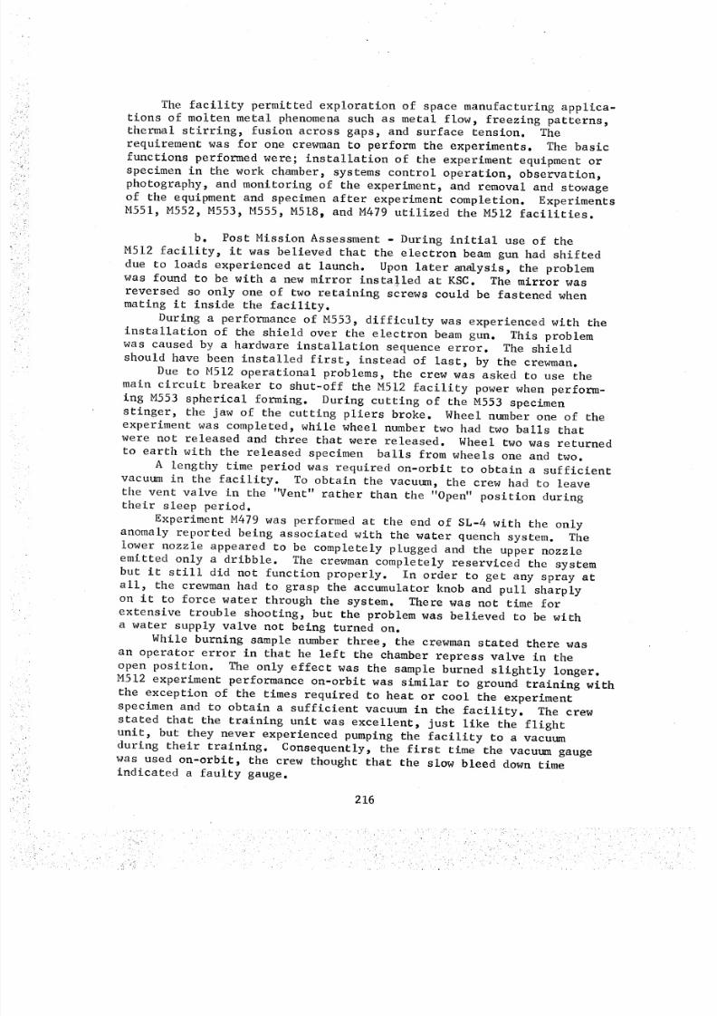
8/8/2019 MSFC Skylab Crew Systems Mission Evaluation
http://slidepdf.com/reader/full/msfc-skylab-crew-systems-mission-evaluation 240/397
The facility permitted exploration of space manufacturing applica-
tions of molten metal phenomena such as metal flow, freezing patterns,thermal stirring, fusion across gaps, and surface tension. The
requirement was for one crewman to perform the experiments. The basic
functions performed were; installation of the experiment equipment or
specimen in the work chamber, systems control operation, observation,
photography, and monitoring of the experiment, and removal and stowage
of the equipment and specimen after experiment completion. ExperimentsM551, M552, M553, M555, M518, and M479 utilized the M512 facilities.
b. Post Mission Assessment - During initial use of the
M512 facility, it was believed that the electron beam gun had shifted
due to loads experienced at launch. Upon later an_ysis, the problemwas found to be with a new mirror installed at KSC. The mirror was
reversed so only one of two retaining screws could be fastened when
mating it inside the facility.
During a performance of M553, difficulty was experienced with the
installation of the shield over the electron beam gun. This problemwas caused by a hardware installation sequence error. The shield
should have been installed first, instead of last, by the crewman.
Due to M512 operational problems, the crew was asked to use the
main circuit breaker to shut-off the M512 facility power when perform-
ing M553 spherical forming. During cutting of the M553 specimen
stinger, the jaw of the cutting pliers broke. Wheel number one of the
experiment was completed, while wheel number two had two balls that
were not released and three that were released. Wheel two was returned
to earth with the released specimen balls from wheels one and two.
A lengthy time period was required on-orbit to obtain a sufficient
vacuum in the facility. To obtain the vacuum, the crew had to leave
the vent valve in the "Vent" rather than the "Open" position duringtheir sleep period.
Experiment M479 was performed at the end of SL-4 with the only
anomaly reported being associated with the water quench system. The
lower nozzle appeared to be completely plugged and the upper nozzle
emitted only a dribble. The crewman completely reserviced the system
but it still did not function properly. In order to get any spray at
all, the crewman had to grasp the accumulator knob and pull sharplyon it to force water through the system. There was not time for
extensive trouble shooting, but the problem was believed to be witha water supply valve not being turned on.
While burning sample number three, the crewman stated there was
an operator error in that he left the chamber repress valve in the
open position. The only effect was the sample burned slightly longer.M512 experiment performance on-orbit was similar to ground training with
the exception of the times required to heat or cool the experiment
specimen and to obtain a sufficient vacuum in the facility. The crew
stated that the training unit was excellent, just like the flightunit, but they never experienced pumping the facility to a vacuum
during their training. Consequently, the first time the vacuum gaugewas used on-orbit, the crew thought that the slow bleed down time
indicated a faulty gauge.
216
8/8/2019 MSFC Skylab Crew Systems Mission Evaluation
http://slidepdf.com/reader/full/msfc-skylab-crew-systems-mission-evaluation 241/397
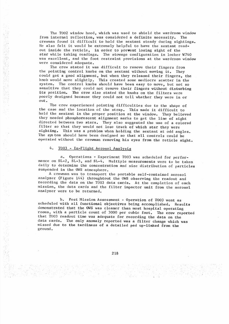
8/8/2019 MSFC Skylab Crew Systems Mission Evaluation
http://slidepdf.com/reader/full/msfc-skylab-crew-systems-mission-evaluation 242/397
The TO02window hood, which was used to shield the wardroomwindowfrom internal reflection, was considered a definite necessity. Thecrewmanfound it difficult to hold the sextant steady during sightings.He also felt it would be extremely helpful to have the sextant read-out inside the reticle, in order to prevent losing sight of thestar while taking readings. The stowage configuration in locker W740was excellent, and the foot restraint provisions at the wardroomwindowwere considered adequate.
The crew stated it was difficult to remove their fingers fromthe pointing control knobs on the sextant without moving it. Theycould get a good alignment, but when they released their fingers, theknob would moveslightly. This created somemediocre scatter in thesystem. The control knobs should have been easy to move, but not sosensitive that they could not removetheir fingers without disturbingits position. The crew also stated the knobs on the filters werepoorly designed because they could not tell whether they were in orout.
The crew experienced pointing difficulties due to the shape ofthe case and the location of the strap. This madeit difficult tohold the sextant in the proper position at the window. They believedthey neededphosphorescent alignment marks to get the line of sightdirected between two stars. They also suggested the use of a coloredfilter so that they would not lose track of which star they weresighting. This was a problem whenholding the sextant at odd angles.The system should have been designed so that all controls could beoperated without the crewmanremoving his eyes from the reticle sight.
4. T003 - In-Flight Aerosol Analysis
a. Operations - Experiment T003 was scheduled for perfor-mance on SL-2, SL-3, and SL-4. Multiple measurements were to be taken
daily to determine the concentration and size distribution of particlessuspended in the OWS atmosphere.
A crewman was to transport the portable self-contained aerosol
analyzer (Figure 144) throughtout the OWS observing the readout and
recording the data on the T003 data cards. At the completion of each
mission, the data cards and the filter impactor unit from the aerosolanalyzer were to be returned.
b. Post Mission Assessment - Operation of T003 went as
scheduled with all functional objectives being accomplished. Results
demonstrated that the OWS was cleaner than most hospital operating
rooms, with a particle count of 3000 per cubic foot. The crew reportedthat T003 readout time was adequate for recording the data on the
data cards. The only anomaly reported was a filter change which was
missed due to the tardiness of a detailed pad up-linked from theground.
218
8/8/2019 MSFC Skylab Crew Systems Mission Evaluation
http://slidepdf.com/reader/full/msfc-skylab-crew-systems-mission-evaluation 243/397
8/8/2019 MSFC Skylab Crew Systems Mission Evaluation
http://slidepdf.com/reader/full/msfc-skylab-crew-systems-mission-evaluation 244/397
CANISTER OCCULTING DISC'_ _ASSI_InLY
Figure 145. T025 Experiment IVA Operational Configuration|
the T025 hardware to obtain some experiment S073-Gegenschein and
Zodiacal light photography. The equipment was installed upside-downin the anti-solar SAL with the occulting disc positioned out of the
camera's field of view. During this operation, the crewman used his
finger to control the DAC shutter release. This proved to be difficult
and fatiguing. In readiness for subsequent operations, the DAC was
prepared for operation with the DAC push button cable. However, the
crew was not directed to repeat the experiment.
As an alternate method of performing T025 and viewing the Kohoutekcomet, an EVA bracket, to attach the T025 canister to an external
truss, was designed and launched on SL-3. The SL-3 crew fit-checked
the bracket to the T025 experiment and attached operational decals inreadiness for EVA deployment on SL-4.
Problems occurred during the first SL-4 EVA operation of T025
which prohibited the acquisition of all planned data. Five photographs,out of a planned forty, were obtained. The view finder on the camera
was loose and the shutter speed knob came off during operation. The
crewman was able to reinstall the knob, but it did not engage enough
to permit use. During EVA trouble shooting of the T025 equipment,the thermal blanket cover was removed. The T025 hardware was stowed
in the AM to permit further troubleshooting at a more opportune time.
After completion of the EVA, the crew successfully repaired the shutter
speed knob and the T025 hardware was utilized during subsequent EVA'sto obtain ultraviolet and visible photographs of the Kohoutek comet.
All subsequent T025 experiment performances were performed withoutincident.
220
8/8/2019 MSFC Skylab Crew Systems Mission Evaluation
http://slidepdf.com/reader/full/msfc-skylab-crew-systems-mission-evaluation 245/397
The T025 experiment was performed from the anti-solar SALwithonly minor problems. The T025hookup with the extension rod workedwell and the procedures/checklists and hardware used for night photo-graphy were adequate. Pad updates for the experiment reminded thecrew to inhibit the fire sensors prior to experiment initiation because
the Caution and Warning System alarm was activated on SL-3 when theSALwas openedwith T025 installed.T025 was not originally designed for EVA use but, with the addi-
tion of the specially designed EVAbracket and filters, (illustratedin Section VI. E), ultraviolet and visible photographs of theKohoutek comet were obtained.
6. T027 - Sample Array
a. Operations - The T027 Sample Array (SA) experiment
performance was scheduled during SL-2 to acquire data for determining
the change in optical properties of various transmissive windows,mirrors, and defraction gratings, cause by deposition of contaminantsfound about the orbital assembly.
The experiment equipment included a canister system with one
extension rod, an ejection rod, and a launch stowage container. One
crewman was to prepare the T027 SA experiment and then install it
through the anti-solar SAL for exposure to the space environment.
Upon completion of the exposure, the SA was to be retracted, removedfrom the SAL and restrowed in its launch container for return.
Experiment hardware is illustrated in Figure 146 and 147.
b. Post Mission Assessment - The T027 experiment was
installed in the anti-solar SAL and deployed as planned. Due to the
parasol deployment and resulting requirements for usage of the anti-
solar SAL by other experiments, the T027 SA exposure time was reduced.
The problem identified during operation of T027 occurred duringthe closure of the array valve prior to retraction and removal of
the SA system from the SAL. When the crewman closed the array valve
by turning the vane control, the valve did not seat completely.
Force, in excess of that recommended during training, was applied tothe vane control and the valve was closed. The problem was attributed
to the low temperature of the system, causing frost to form, thuspreventing normal closure.
The requirement to let the T027 SA system warm-up prior to its
removal from the SAL had been eliminated from the checklist and
consequently omitted from the experiment pad. This procedural informa-
tion was definately necessary, as indicated by the minor problem whichoccurred with the array valve.
221
8/8/2019 MSFC Skylab Crew Systems Mission Evaluation
http://slidepdf.com/reader/full/msfc-skylab-crew-systems-mission-evaluation 246/397
8/8/2019 MSFC Skylab Crew Systems Mission Evaluation
http://slidepdf.com/reader/full/msfc-skylab-crew-systems-mission-evaluation 247/397
E. Operations Experiments
i. M487 - Habitability/Crew Quarters
a. Operations - Experiment M487 was scheduled for each of
the three Skylab missions for evaluating and reporting on the OWShabitability provisions.
The methods of M487 data collection were dependent primarily onthe crewmen. Where possible, the experiment task was to augment orcoincide with the operational activity being observed. When an
activity was not scheduled or predictable, the elements of the activitywere to be grouped into a staged demonstration to optimize time and
effort. First the crewman was required to obtain, calibrate as re-
quired, and position the various monitoring devices throughout the OWS.The crewman then had to obtain, position, and operate the various
equipment required for photography and data collection.
b. Post Mission Assessment - M487 was performed as plannedthroughout each Skylab mission, accomplishing all pre-mission require-
ments.
During the initial calibration of the sound level meter/frequencyanalyzer, the crewman could not obtain the correct calibration factor.
A second calibration was attempted at a later time and the correct
factor was obtained. The cause of the problem encountered during thefirst calibration attempt was undetermined.
The crews considered much of the equipment supplied to supportthe M487 experiment as unnecessary, as was shown by its lack of use
throughout the Skylab missions. For this reason, few comments concern-
ing the M487 hardware were available. It was reported that both the
ambient and digital thermometers required a lengthy time to stabilize
when measurements were made where a large change in temperature wasinvolved. Both the digital and ambient thermometers were used over
the three Skylab missions in support of other hardware evaluation and
the lO-foot tape was used in several science demonstrations. These
items should be included on future missions as operational supporthardware.
Some crewmembers expressed annoyance toward the lengthy and timeconsuming on-board debriefings. They felt that this orbit time could
have been better utilized and that the debriefings could have beenconducted post-mission.
It is intended that the data compiled from M487 will form the
basis for verifying existing spacecraft habitability criteria and will
establish requirements for more advanced spacecraft.
2. M509 - Astronaut Maneuvering Equipmen_
a. Operations Experiment M509 was scheduled to be performedon SL-2 and SL-3. Each test pilot was scheduled to perform four runs
223
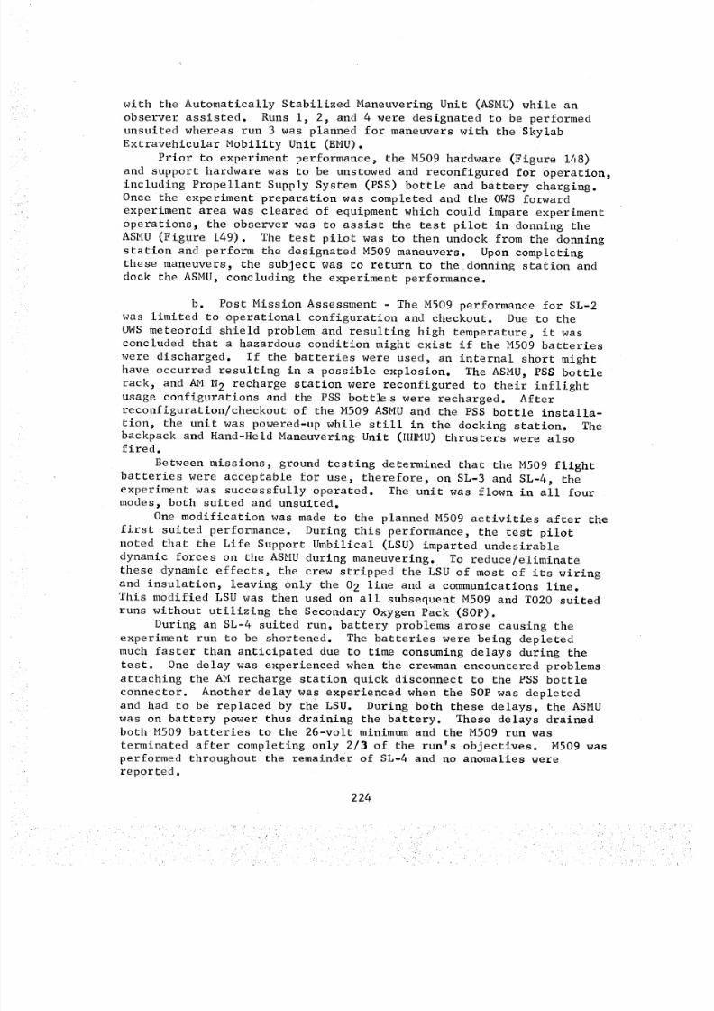
8/8/2019 MSFC Skylab Crew Systems Mission Evaluation
http://slidepdf.com/reader/full/msfc-skylab-crew-systems-mission-evaluation 248/397
with the Automatically Stabilized Maneuvering Unit (ASMU)while anobserver assisted. Runs i, 2, and 4 were designated to be performedunsuited whereas run 3 was planned for maneuverswith the SkylabExtravehicular Mobility Unit (EMU).
Prior to experiment performance, the M509hardware (Figure 148)and support hardware was to be unstowed and reconfigured for operation,including Propellant Supply System (PSS) bottle and battery charging.Once the experiment preparation was completed and the OWSorwardexperiment area was cleared of equipment which could impare experimentoperations, the observer was to assist the test pilot in donning theASMU(Figure 149). The test pilot was to then undock from the donningstation and perform the designated M509maneuvers. Upon completingthese maneuvers, the subject was to return to thedonning station anddock the ASMU,concluding the experiment performance.
b. Post Mission Assessment - The M509 performance for SL-2was limited to operational configuration and checkout. Due to the
OWSmeteoroid shield problem and resulting high temperature, it wasconcluded that a hazardous condition might exist if the M509batterieswere discharged. If the batteries were used, an internal short mighthave occurred resulting in a possible explosion. The ASMU,PSSbottlerack, and AMN2 recharge station were reconfigured to their inflightusage configurations and the PSSbott_s were recharged. Afterreconfiguration/checkout of the M509ASMUand the PSSbottle installa-tion, the unit was powered-up while still in the docking station. Thebackpack and Hand-Held Maneuvering Unit (HHMU)thrusters were alsofired.
Betweenmissions, ground testing determined that the M509 flightbatteries were acceptable for use, therefore, on SL-3 and SL-4, theexperiment was successfully operated. The unit was flown in all fourmodes, both suited and unsuited.
Onemodification was made to the planned M509activities after thefirst suited performance. During this performance, the test pilotnoted that the Life Support Umbilical (LSU) imparted undesirabledynamic forces on the ASMUduring maneuvering. To reduce/eliminatethese dynamic effects, the crew stripped the LSUof most of its wiringand insulation, leaving only the 02 line and a communications line.This modified LSUwas then used on all subsequent M509 and TO20suitedruns without utilizing the SecondaryOxygenPack (SOP).
During an SL-4 suited run, battery problems arose causing theexperiment run to be shortened. The batteries were being depletedmuchfaster than anticipated due to time consumingdelays during the
test. One delay was experienced when the crewmanencountered problemsattaching the AMrecharge station quick disconnect to the PSSbottleconnector. Another delay was experienced when the SOPwas depletedand had to be replaced by the LSU. During both these delays, the ASMUwas on battery power thus draining the battery. These delays drainedboth M509batteries to the 26-volt minimumand the M509run wasterminated after completing only 2/3 of the run's objectives. M509wasperformed throughout the remainder of SL-4 and no anomalies werereported.
224
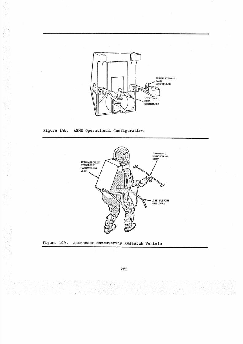
8/8/2019 MSFC Skylab Crew Systems Mission Evaluation
http://slidepdf.com/reader/full/msfc-skylab-crew-systems-mission-evaluation 249/397
Figure 148.i
ASMU Operational Configuration
AUTOHATICAL_
STABILIZED
MANEUVERING
UNIT
HAND-HELD
MANEUVERING
UNIT
SUPPORT
UMBILICAL
Figure 149. Astronaut Maneuvering Research Vehicle
225
8/8/2019 MSFC Skylab Crew Systems Mission Evaluation
http://slidepdf.com/reader/full/msfc-skylab-crew-systems-mission-evaluation 250/397
The M509ASMUwaswell designed and easy to operate. Flighttraining skills, commono all astronauts, was apparently readilytransferred to navigating the ASMU. This transfer of training wasdemonstrated during an unscheduled M509performance by a crewmemberwhohad never trained for M509 or ever used the training simulator. Hisflight was performed with ease and was considered a complete success.During the M509maneuvers, four potential flying modeswereevaluated and, in order of preference, were "DIRECT", "CMG", "RATEGYRO",and'_HMU". The "DIRECT"modewas the easiest and the moreintuitive to control. The "CMG"and "RATEGYRO"modeswere very goodbut the precision, inherent to these modes, was unnecessary and willnot be required for a future EVAmaneuvering device. The HHMUwasgiven a poor rating and was recommendedby the crew to be deleted fromconsideration as an EVAmaneuvering mode. The difficulty with theHHMUwas in locating the center of gravity, which turned out to be animportant factor in this maneuvering mode. In future testing of amaneuvering unit, it is recommendedhat the HHMUbe eliminated fromconsideration because it requires unique and undeveloped operatorskills.
In flying M509, actual EVAconditions were simulated to evaluateall phases of maneuvering. Suited operations were conducted usingboth the LSUand SOP. The SOPconfiguration was preferred over theLSUconfigurations because of the dynamic effects present with the LSU.The LSU, due to its mass and elastic characteristics, imparted aninertia on the M509ASMU,which proved to be annoying to the testpilot, constantly requiring guidance corrections to the unit.
Safety was a principle concern during M509pre-mission designand planning. Due to the ease of operation and maneuverability ofthe ASMU,the pre-mission concern of inadvertant and possible catas-trophic collisions was proven to be unwarranted. The ASMU,thoughvery large and heavy, was handled without difficulty by the test pilot.The test pilots were confident that, even with the large ASMUmass anda maximummaneuvering velocity of 3-4 ft/sec , they could, in the eventof a thruster failure, reposition themselves and absorb the energy ofan impact without bodily or hardware damage.
The crews believed that the M509hardware and supporting equip-ment was well designed from both a functional and integration stand-point. However, the crews one negative commentwas that the ASMUhad too manycontrols located in too manydiverse and remote positions.If possible, these controls should be relocated on a commonpanel tofacilitate crew operations. The safety goggles and ear plugs wereused by all crewmen. The unstowage/stowage of the M509hardware wasstraightforward with no problems occurring. PSSbottle chargingrequired the crew to translate to and from the AMrecharge stationwith the bottles. This entire procedure, including recharge, tookless than i0 minutes to perform. It was reported that the bottlesreached a temperature of approximately lO0°F during recharging. Trans-lation with the bottles was accomplished by the crewmanholding thebottle ahead of him, pushing off and then following along behind thehardware. Prior to reaching his destination, the crewmanwould reposi-tion himself between the hardware and contact point for a safe landing.
226
8/8/2019 MSFC Skylab Crew Systems Mission Evaluation
http://slidepdf.com/reader/full/msfc-skylab-crew-systems-mission-evaluation 251/397
The ASMUwas an acceptable translational device but was found tobe severely limited in its use as a workstation/platform for perform-ing work related tasks. In performing relatively easy tasks, thecrewman's body torques would over saturate the ASMUgyros and causea loss of stability. To perform EVA tasks, the ASMU,as designed,would have to be docked/restrained at the designated work area toachieve the necessary stability required to perform the task.
The next generation EVAmaneuvering device should be back mountedwith the pilot-to-backpack restraint system providing a tight, secure,and comfortable (seat padding recommended)fit. Backpack donning/doffing should be designed as a one-manfunction. The backpack musthave six-degrees of freedom, with the propulsion thrusters locatedaround the center of gravity of the pilot/backpack combination, andshould be hand controlled. The hand controllers should have thecapability of being relocated during flight to allow multiple workingpostures for the pilot. The "DIRECT"modeshould be selected as themaneuvering modewith a capability of a 3-4 ft/sec velocity. Restraints/docking provisions, i.e., manipulative arms must be provided toadequately stabilize the pilot and permit him to perform the designatedtask. A backpack spotlight should be incorporated to provide thepilot with an illumination source at his work area. Separate isola-tion valves/circuit breakers for each thruster, or set of thrusters,should be provided to insure against a single point failure. Ideally,backpack should contain all systems required for EVA, such as, pressurecontrol, oxygen, and maneuvering systems, with all system monitoringdisplays/readouts being illuminated. Incorporation of a safetytether should also be considered.
3. TOI3 - Crew/Vehicle Disturbances
a. Operations - Experiment TOI3 was scheduled for performanceon SL-3 to measure the effects of crew motions on the dynamics ofmanned spacecraft.
Two crewmen were required for T013 operations; one designated asthe subject and the other as the observer. A third crewman was
required during performance of the worst case control system inputtask. Data collection involved the use of the 16mm DAC, mounted in
the OWS forward compartment and experiment and vehicle telemetry. The
Limb Motion Sensor (LIMS) suit assembly, including the LIMS data cable,was to be unstowed, donned by the subject, and then connected to the
experiment data cable between the LIMS and the Experiment Data System
(EDS). Prior to start of the experiment, the observer was to don a
communications headset and turn on the AM tape recorder and cameras for
data collection. The Force Measurement Units (FMU) were to then be
uncaged and calibrated. During the experiment performance of body
and limb motions and free soaring activities, the observer was to
assist in securing the subject to, and releasing him from, FMU No. i
at appropriate times during the experiment. Experiment operational
227
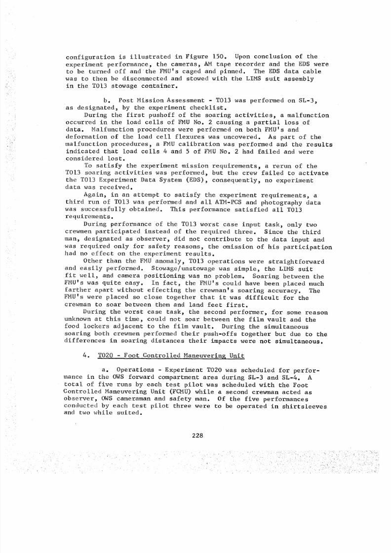
8/8/2019 MSFC Skylab Crew Systems Mission Evaluation
http://slidepdf.com/reader/full/msfc-skylab-crew-systems-mission-evaluation 252/397
configuration is illustrated in Figure 150. Upon conclusion of theexperiment performance, the cameras, AM tape recorder and the EDSwereto be turned off and the FMU's caged and pinned. The EDSdata cablewas to then be disconnected and stowed with the LIMS suit assemblyin the TOI3 stowage container.
b. Post Mission Assessment- T013 was performed on SL-3,as designated, by the experiment checklist.
During the first pushoff of the soaring activities, a malfunctionoccurred in the load cells of FMUNo. 2 causing a partial loss ofdata. Malfunction procedures were performed on both FMU's anddeformation of the load cell flexures was uncovered. As part of themalfunction procedures, a FMUcalibration was performed and the resultsindicated that load cells 4 and 5 of FMUNo. 2 had failed and wereconsidered lost.
To satisfy the experiment mission requirements, a rerun of theTOI3 soaring activities was performed, but the crew failed to activate
the T013 Experiment Data System (EDS), consequently, no experimentdata was received.Again, in an attempt to satisfy the experiment requirements, a
third run of T013was performed and all ATM-PCSand photography datawas successfully obtained. This performance satisfied all T013requirements.
During performance of the TOI3 worst case input task, only twocrewmenparticipated instead of the required three. Since the thirdman, designated as observer, did not contribute to the data input andwas required only for safety reasons, the omission of his participationhad no effect on the experiment results.
Other than the FMUanomaly, T013 operations were straightforwardand easily performed. Stowage/unstowagewas simple, the LIMS suitfit well, and camerapositioning was no problem. Soaring between theFMU'swas quite easy. In fact, the FMU's could have been placed muchfarther apart without effecting the crewman's soaring accuracy. TheFMU's were placed so close together that it was difficult for thecrewmanto soar between them and land feet first.
During the worst case task, the second performer, for somereasonunknownat this time, could not soar between the film vault and thefood lockers adjacent to the film vault. During the simultaneoussoaring both crewmenperformed their push-offs together but due to thedifferences in soaring distances their impacts were not simultaneous.
4. TO20 - Foot Controlled Maneuvering Unit
a. Operations Experiment T020 was scheduled for perfor-mance in the OWS forward compartment area during SL-3 and SL-4. A
total of five runs by each test pilot was scheduled with the FootControlled Maneuvering Unit (FCMU) while a second crewman acted as
observer, OWS cameraman and safety man. Of the five performances
conducted by each test pilot three were to be operated in shirtsleevesand two while suited.
228
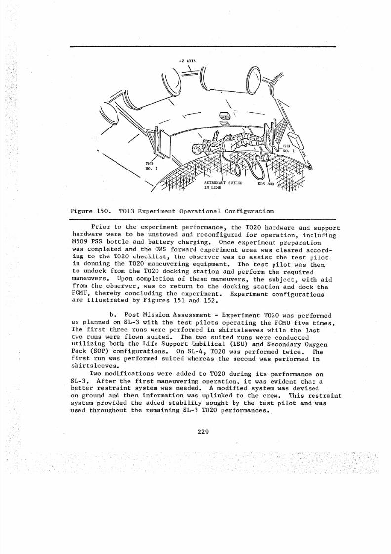
8/8/2019 MSFC Skylab Crew Systems Mission Evaluation
http://slidepdf.com/reader/full/msfc-skylab-crew-systems-mission-evaluation 253/397
Figure 150. TOI3 Experiment Operational Configuration
Prior to the experiment performance, the T020 hardware and support
hardware were to be unstowed and reconfigured for operation, including
M509 PSS bottle and battery charging. Once experiment preparation
was completed and the OWS forward experiment area was cleared accord-
ing to the T020 checklist, the observer was to assist the test pilot
in donning the TO20 maneuvering equipment. The test pilot was then
to undock from the TO20 docking station and perform the requiredmaneuvers. Upon completion of these maneuvers, the subject, with aid
from the observer, was to return to the docking station and dock the
FCMU, thereby concluding the experiment. Experiment configurationsare illustrated by Figures 151 and 152.
b. Post Mission Assessment - Experiment T020 was performed
as planned on SL-3 with the test pilots operating the FCMU five times.The first three runs were performed in shirtsleeves while the last
two runs were flown suited. The two suited runs were conducted
utilizing both the Life Support Umbilical (LSU) and Secondary Oxygen
Pack (SOP) configurations. On SL-4, T020 was performed twice. The
first run was performed suited whereas the second was performed in
shirtsleeves.
Two modifications were added to TO20 during its performance on
SL-3. After the first maneuvering operation, it was evident that a
better restraint system was needed. A modified system was devised
on ground and then information was uplinked to the crew. This restraint
system provided the added stability sought by the test pilot and was
used throughout the remaining SL-3 TO20 performances.
229
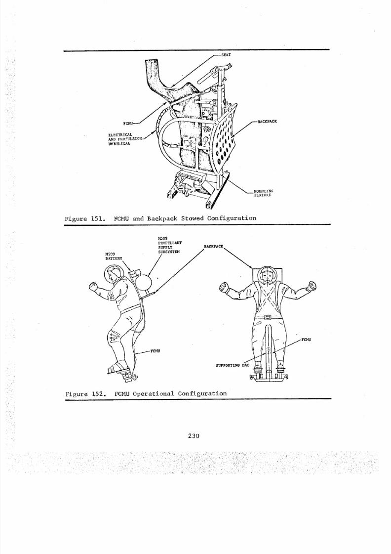
8/8/2019 MSFC Skylab Crew Systems Mission Evaluation
http://slidepdf.com/reader/full/msfc-skylab-crew-systems-mission-evaluation 254/397
• i i i i
ELECTRICAL
AND ]
1)MBILICAL
EAT
Figure 151. FCMU and Backpack Stowed Configuration
Figure
M509
PROPELLAN'r
SUPPLY
M509 "_
BATTERY
BAC_ACK
I.5
SUPPORTING D_
152. FCMU Operational Configuration
230
_: _:i:_;;k'_iv,:_'. _ ,__i_
8/8/2019 MSFC Skylab Crew Systems Mission Evaluation
http://slidepdf.com/reader/full/msfc-skylab-crew-systems-mission-evaluation 255/397
A second modification was performed by the SL-3 crew on the LSU
in hopes of reducing or eliminating the dynamic effects it imparted
on the maneuvering units. Using a scalpel and scissors, the LSU was
stripped of most wiring and insulation, leaving only the 02 line andcommunications line. This LSU was used on all subsequent M509 and
TO20 suited runs not utilizing theSOP configuration.Because of the lack of rigidity experienced with the TO20
restraint system during SL-3, a new, rigid restraint system wasdesigned and fabricated between missions. This rigid restraint
system was launched on SL-4 and used by the crew in their TO20 opera-t ions.
The first SL-4 T020 run was performed suited and utilized the
new restraint system. The crew reported that the system worked
extremely well and reduced practically all body/backpack motions.
The second T020 performance was conducted in shirtsleeves. The
crew operated T020 with both the rigid and original restraint systems.
Again, the rigid system was considered highly effective whereas the
non-rigid system was considered extremely poor.
This was the last evaluation of experiment T020 as scheduling
considerations prohibited any additional performances.
TO20 stowage/unstowage was fairly simple, although between
operations it was left stowed in such a manner requiring a minimum of
reactivation time...a casual type of stowage.
The T020 restraints and harness were not satisfactory. Also,
seat padding was improvised and is definitely required. The restraints
did not give the operator a secure or tight feeling in the unit. The
harness, due to its unusual design, was difficult to don and connect.
The backpack assembly was not contoured correctly and was too loose
when donned. Incorporation of the required restraint system removed
most of the "play" between the backpack and FCMU and gave the pilot
a more secure fit with the T020 hardware.The shoe plates seemed to work well, although it was easy to
kick one's foot/shoe plate out of the FCMU. Also, the shoe plate
forces required for thruster control were too high. These seemingly
high shoe plate forces could be attributed to a possible deconditioningof the crew's leg muscles due to the zero-gravity environment.
T020 should have had six-degrees of freedom for fair comparison
with M509 (which was not the intent of the experiment). As designed,
it is unacceptable as a maneuvering vehicle and the crew saw no
advantage in its concept of foot-controlled maneuvering.
231
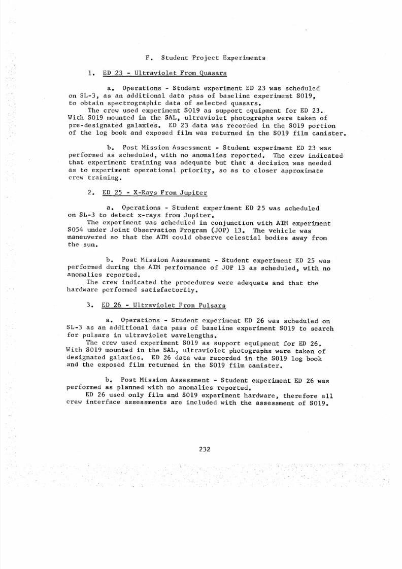
8/8/2019 MSFC Skylab Crew Systems Mission Evaluation
http://slidepdf.com/reader/full/msfc-skylab-crew-systems-mission-evaluation 256/397
F. Student Project Experiments
i. ED 23 - Ultraviolet From Quasars
a. Operations - Student experiment ED 23 was scheduled
on SL-3, as an additional data pass of baseline experiment S019,
to obtain spectrographic data of selected quasars.
The crew used experiment S019 as support equipment for ED 23.
With S019 mounted in the SAL, ultraviolet photographs were taken of
pre-designated galaxies. ED 23 data was recorded in the SOl9 portionof the log book and exposed film was returned in the S019 film canister.
b. Post Mission Assessment - Student experiment ED 23 was
performed as scheduled, with no anomalies reported. The crew indicatedthat experiment training was adequate but that a decision was needed
as to experiment operational priority, so as to closer approximate
crew training.
2. ED 25 - X-Rays From Jupiter
a. Operations - Student experiment ED 25 was scheduled
on SL-3 to detect x-rays from Jupiter.
The experiment was scheduled in conjunction with ATM experimentS054 under Joint Observation Program (JOP) 13. The vehicle was
maneuvered so that the ATM could observe celestial bodies away fromthe sun.
b. Post Mission Assessment - Student experiment ED 25 was
performed during the ATM performance of JOP 13 as scheduled, with noanomalies reported.
The crew indicated the procedures were adequate and that the
hardware performed satisfactorily.
3. ED 26 - Ultraviolet From Pulsars
a. Operations - Student experiment ED 26 was scheduled on
SL-3 as an additional data pass of baseline experiment S019 to searchfor pulsars in ultraviolet wavelengths.
The crew used experiment S019 as support equipment for ED 26.
With S019 mounted in the SAL, ultraviolet photographs were taken of
designated galaxies. ED 26 data was recorded in the S019 log bookand the exposed film returned in the SOl9 film canister.
b. Post Mission Assessment - Student experiment ED 26 wasperformed as planned with no anomalies reported.
ED 26 used only film and SOl9 experiment hardware, therefore allcrew interface assessments are included with the assessment of S019.
232
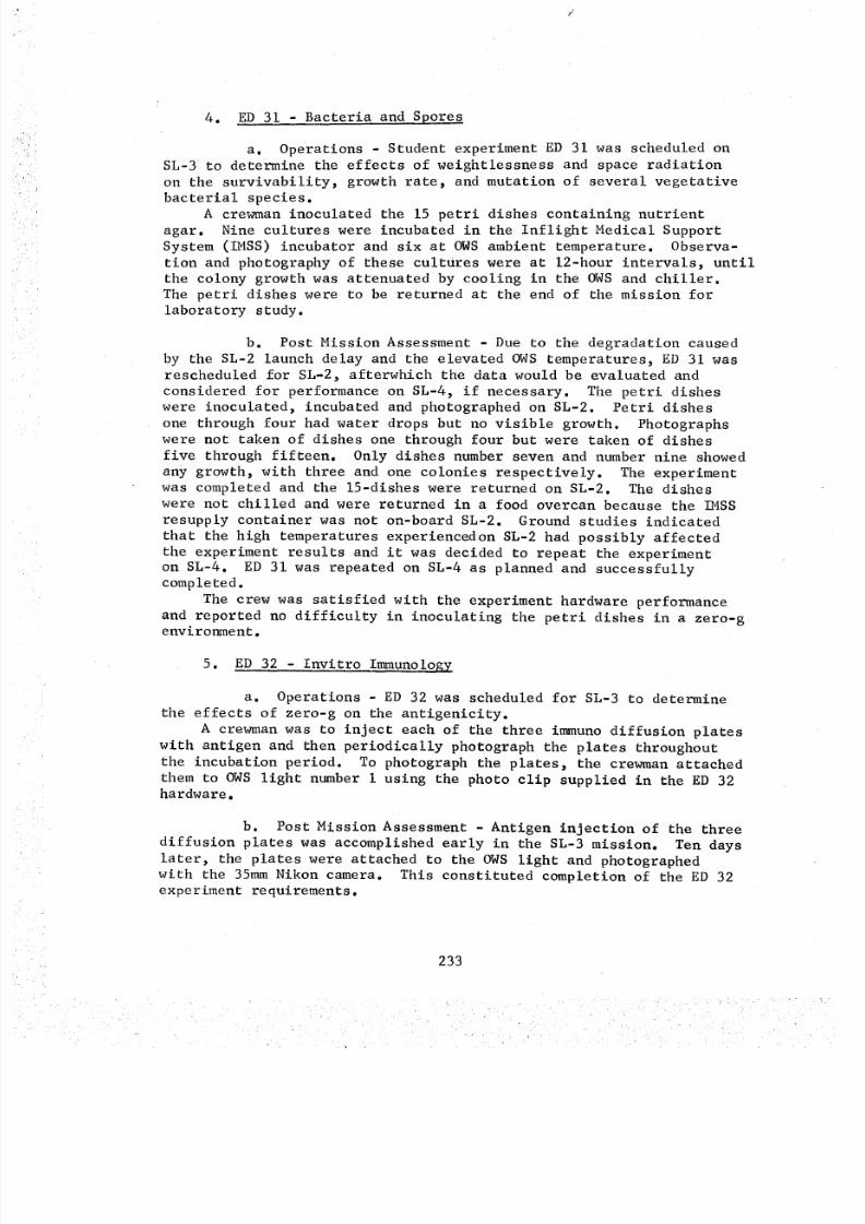
8/8/2019 MSFC Skylab Crew Systems Mission Evaluation
http://slidepdf.com/reader/full/msfc-skylab-crew-systems-mission-evaluation 257/397
4. ED 31 - Bacteria and Spores
a. Operations - Student experiment ED 31 was scheduled on
SL-3 to determine the effects of weightlessness and space radiation
on the survivability, growth rate, and mutation of several vegetative
bacterial species.A crewman inoculated the 15 petri dishes containing nutrient
agar. Nine cultures were incubated in the Inflight Medical Support
System (IMSS) incubator and six at OWS ambient temperature. Observa-
tion and photography of these cultures were at 12-hour intervals, until
the colony growth was attenuated by cooling in the OWS and chiller.
The petri dishes were to be returned at the end of the mission forlaboratory study.
b. Post Mission Assessment - Due to the degradation caused
by the SL-2 launch delay and the elevated OWS temperatures, ED 31 wasrescheduled for SL-2, afterwhich the data would be evaluated and
considered for performance on SL-4, if necessary. The petri dishes
were inoculated, incubated and photographed on SL-2. Petri dishes
one through four had water drops but no visible growth. Photographs
were not taken of dishes one through four but were taken of dishes
five through fifteen. Only dishes number seven and number nine showed
any growth, with three and one colonies respectively. The experiment
was completed and the 15-dishes were returned on SL-2. The dishes
were not chilled and were returned in a food overcan because the IMSS
resupply container was not on-board SL-2. Ground studies indicated
that the high temperatures experiencedon SL-2 had possibly affected
the experiment results and it was decided to repeat the experiment
on SL-4. ED 31 was repeated on SL-4 as planned and successfullycompleted.
The crew was satisfied with the experiment hardware performanceand reported no difficulty in inoculating the petri dishes in a zero-genvironment.
5. ED 32 - Invitro ImmunoloEy
a. Operations - ED 32 was scheduled for SL-3 to determine
the effects of zero-g on the antigenicity.
A crewman was to inject each of the three immuno diffusion plates
with antigen and then periodically photograph the plates throughout
the incubation period. To photograph the plates, the crewman attached
them to OWS light number i using the photo clip supplied in the ED 32hardware.
b. Post Mission Assessment - Antigen injection of the three
diffusion plates was accomplished early in the SL-3 mission. Ten days
later, the plates were attached to the OWS light and photographed
with the 35mm Nikon camera. This constituted completion of the ED 32experiment requirements.
233
8/8/2019 MSFC Skylab Crew Systems Mission Evaluation
http://slidepdf.com/reader/full/msfc-skylab-crew-systems-mission-evaluation 258/397
No assessments or recommendationswere received from the crewconcerning ED 32. Therefore, it is assumedthat the experiment hard-ware, procedures and interfaces were well designed and all functionedas planned.
6. ED 41 - Motor Sensory Performance
a. Operations - ED 41, Motor Sensory Performance, was
scheduled on SL-4 to obtain motor sensor performance data which could
be used in planning, training, and equipment development for future
manned space missions.
The method of measuring motor sensory performance used in ED 41
was a standardized eye-hand coordination test using a maze with a
ll9-hole aiming pattern, stylus, and cable assembly as illustrated inFigure 153. During operation, the unit was attached to the wardroom
window shelf by velcro strips and the cable was connected to the
speaker intercom assembly connector. The experiment was performed
once early and again late in the mission by the same astronaut.
No activities, imposing either intense physical exertion or mental/
emotional strain, was to precede performance of the experiment.
Inflight performance was compared with pre-flight and post-flighttests performed by the same subject.
b. Post Mission Assessment - Student experiment ED 41 was
performed as scheduled with no anomalies reported. Procedures for
ED 41 were straightforward and the hardware performed satisfactorily.
7. ED 52 - Web Formation
a. Operations - Experiment ED 52 was scheduled on SL-3 to
observe the web building process of the Araneous Diadematus (Cross)Spider in a zero-gravity environment and to compare this process with
one performed in a one-g earth environment. A prime and backupspider were launched.
The crewman performing the experiment deployed the experiment
enclosure which permitted observations of spider activity. The spider
was released from her vial into the experiment enclosure and allowed
to spin her web. During the experiment performance, a crewman period-
ically provided food and water for the spider. Still photographs were
made with the 35mm Nikon camera and correlated to Ground Elapsed Time
(GET) by voice recorded comments. Movie photographs were to be made
with the 16mm DAC camera utilizing the automatic camera actuator which
detected spider motion to start/stop the motion picture camera.
Experiment operational configuration is illustrated by Figure 154.
Upon completion of the experiment the spiders were to be disposed ofthrough the trash airlock.
b. Post Mission Assessment - Prior to releasing the primespider, Arabella, the crew reported a problem with the automatic
camera actuator. Malfunction procedures were conducted on the automatic
234
8/8/2019 MSFC Skylab Crew Systems Mission Evaluation
http://slidepdf.com/reader/full/msfc-skylab-crew-systems-mission-evaluation 259/397
C AB LE , A SS EM BL _
MAZE AIMING :_'_D
PATTERN ASSEMBLY
_I"YLUS
Figure 153. ED41 Experiment Configurationel i
E,_PERI _NT
IlllLl!l,i lt]l
Figure 154. ED52 Experiment Operational Photographic Configuration
235
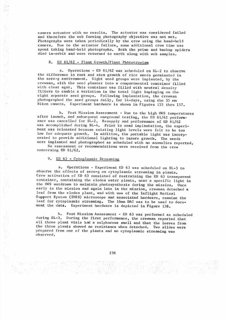
8/8/2019 MSFC Skylab Crew Systems Mission Evaluation
http://slidepdf.com/reader/full/msfc-skylab-crew-systems-mission-evaluation 260/397
camera actuator with no results. The actuator was considered failedand therefore the web forming photography objective was not met.Photographs were taken periodically by the crew using the hand-heldcamera. Due to the actuator failure, someadditional crew time wasspent taking hand-held photographs. Both the prime and backup spidersdied in-orbit and were returned to earth along with web samples.
8. E D 61/62 - Plant Growth/Plant Phbtotropism
a. Operations - ED 61/62 was scheduled on SL-2 to observe
the difference in root and stem growth of rice seeds germinated in
the zero-g environment. Eight seed groups were implanted, by the
crewman, with the seed planter into a compartmental container filled
with clear agar. This container was filled with neutral density
filters to enable a variation in the total light impinging on theeight separate seed groups. Following implantation, the crewman
photographed the seed groups daily, for 14-days, using the 35 mm
Nikon camera. Experiment hardware is shown in Figures 155 thru 157.
b. Post Mission Assessment - Due to the high OWS temperatures
after launch, and subsequent on-ground testing, the ED 61/62 perform-
ance was cancelled for SL-2. Resupply and performance of ED 61/62
was accomplished during SL-4. Prior to seed implantation, the experi-ment was relocated because existing light levels were felt to be too
low for adequate growth. In addition, the portable light was incorp-orated to provide additional lighting to insure growth. The seeds
were implanted and photographed as scheduled with no anomalies reported.No assessment or recommendations were received from the crew
concerning ED 61/62.
9. ED 63 - Cytoplasmic Streaming
a. Operations - Experiment ED 63 was scheduled on SL-3 to
observe the effects of zero-g on cytoplasmic streaming in plants.
Crew activation of ED 63 consisted of restraining the ED 63 transparent
container, containing the elodea water plants, near a specific light in
the OWS wardroom to maintain photosynthesis during the mission. Once
early in the mission and again late in the mission, crewman detached a
leaf from the elodea plant, and with use of the Inflight Medical
Support System (IMSS) microscope and associated hardware, examine the
leaf for cytoplasmic streaming. The 16mm DAC was to be used to docu-
ment the data. Experiment hardware is depicted in Figure 158.
b. Post Mission Assessment - ED 63 was performed as scheduled
during SL-3. During the first performance, the crewman reported that
all three plant vials had a sulphurous smell and that the leaves from
the three plants showed no resistance when detached. Two slides were
prepared from one of the plants and no cytoplasmic streaming wasobserved.
236
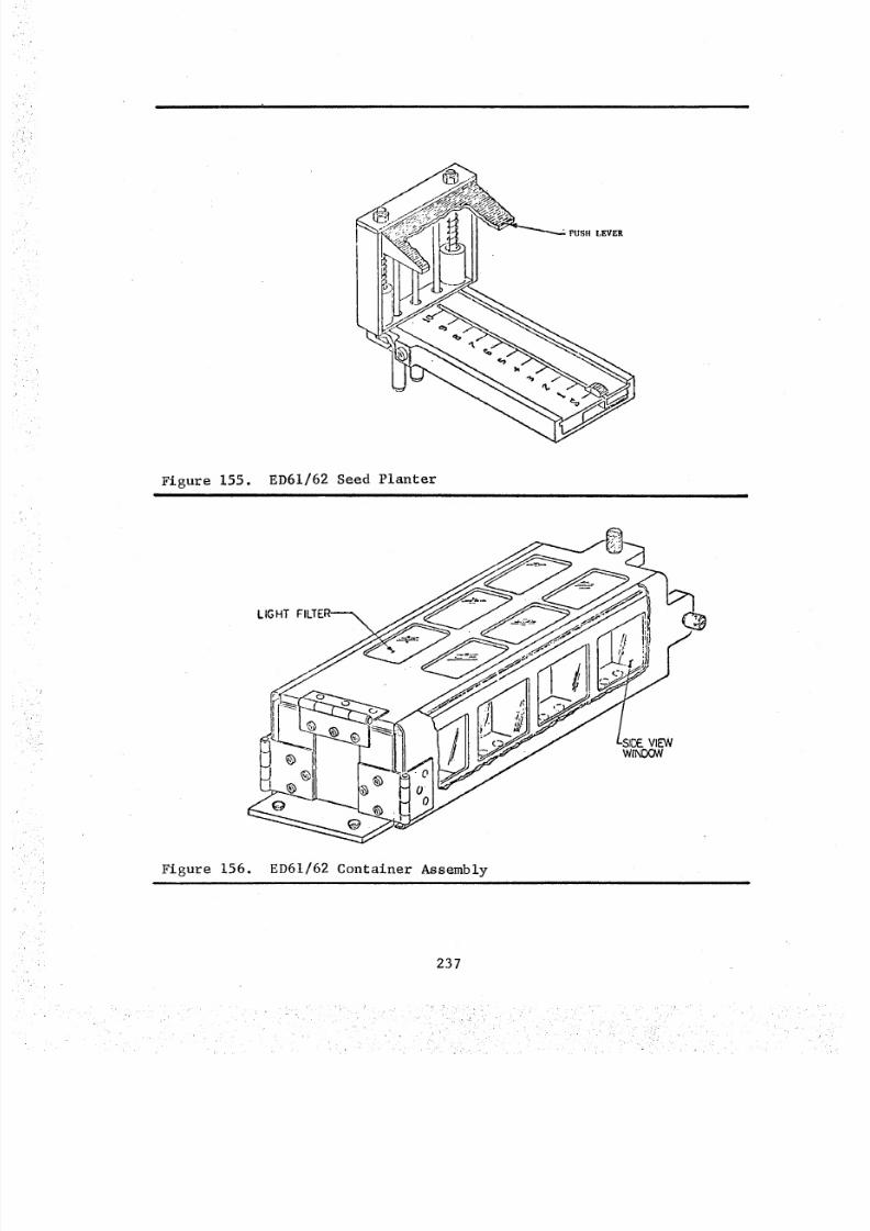
8/8/2019 MSFC Skylab Crew Systems Mission Evaluation
http://slidepdf.com/reader/full/msfc-skylab-crew-systems-mission-evaluation 261/397
Figure 155. ED61/62 Seed Planteri
LIGHT
Figure 156. ED61/62 Container Assembly
237
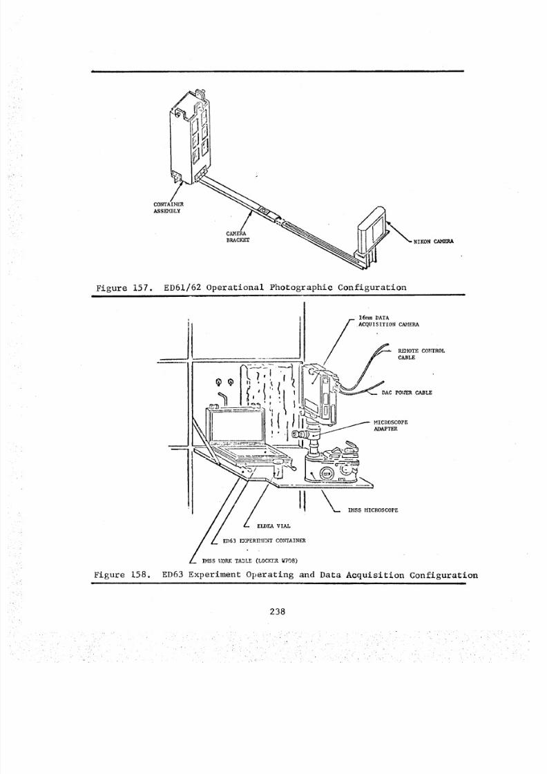
8/8/2019 MSFC Skylab Crew Systems Mission Evaluation
http://slidepdf.com/reader/full/msfc-skylab-crew-systems-mission-evaluation 262/397
CONTAINER
A,SS]_'_IBL¥
CAMERA
BRACKET NIKON
Figure 157.ill i
ED61/62 Operational Photographic Configuration
Figure 158.
!
/16ram DATA
ACQUISITION CAMERA
R _I OT E C O_ rr RO L
CABLE
DAC P01_ER CABLE
MICROSCOPE
ADAPTER
ELDEA VIAL
ED6 3 I _I PERI_I EN T CON TA INER
IMSS_.:ORKA3LE (LOCKERW708)
ED63 Experiment Operating and Data Acquisition Configuration
238
8/8/2019 MSFC Skylab Crew Systems Mission Evaluation
http://slidepdf.com/reader/full/msfc-skylab-crew-systems-mission-evaluation 263/397
In conjunction with performance of ED 63, a ground based test
was performed. A sample slide was prepared on each of the three
plants and observed under a microscope. Two of the three elodea
plants appeared to be totally dead, the third appeared normal and
exhibited good cytoplasmic streaming. The vials containing the two
dead plants smelled of hydrogen sulfide and the leaves showed noresistance when detached. Based on this, it was considered probablethat one or more of the plants in-orbit were dead. From a later
on-ground performance of ED 63, it was discovered that a previously
considered dead plant had exhibited some cytoplasmic streaming.Therefore, the crew was requested to prepare slides on all three
plants and examine for possible streaming. The crew complied; however,
no streaming was detected. This resulted in termination of the experi-
ment for SL-3 and an eventual resupply for a SL-4 performance.
During the SL-4 performance of ED 63, a hardware anomaly was
reported concerning the DAC camera/IMSS microscope adapter. The
crewman examining for cytoplasmic streaming could not acquire a full
field of view. It was his assessment that the adapter was the cause
of the problem.
The SL-4 performance of this experiment approximated the results
obtained from SL-3. During the first cytoplasmic streaming observa-
tion, one plant provided some evidence of streaming. In subsequentobservations, the elodea plant leaves showed no resistance when
detached, there was a sulphurous smell present and no cytoplasmic
streaming was observed. It was decided that the plants were dead andthe experiment was terminated. The plants were removed from their
vials and placed in the trash airlock.
Other than the DAC camera/IMSS microscope adapter anomaly, the
ED 63 performances were conducted as planned. The crew reported that
the experiment procedures and hardware functioned well and that every-
thing possible was done on their part to acquire usable data. Fromthe results of this experiment, it was concluded that zero-g has anundesirable effect on cytoplasmic streaming in plants.
i0. ED 72 - Capillary Study
a. Operations - Experiment ED 72 was scheduled on SL-4 to
demonstrate capillary action as a liquid pumping mechanism.
The experiment hardware consisted of two separate capillary tube
modules and an additional capillary wick module. Each capillary tube
module contained a reservoir, lever valve system and three transparent
capillary tubes of graduated sizes. One module contained water, the
other Krytox oil. The capillary wick module contained three capillaries
of twill and mesh screens. The crewman activated the lever valve of
the capillary tube modules and photograph the capillary action of the
fluid. The entire experimental sequence was photographed, beginningwith the actuation of the capillary valve and ending with the time
that the slowest fluid volume reached the end of the capillary tube.
239
8/8/2019 MSFC Skylab Crew Systems Mission Evaluation
http://slidepdf.com/reader/full/msfc-skylab-crew-systems-mission-evaluation 264/397
8/8/2019 MSFC Skylab Crew Systems Mission Evaluation
http://slidepdf.com/reader/full/msfc-skylab-crew-systems-mission-evaluation 265/397
six detectors continued data collection throughout the Skylab missionsand were deactivated and stowed in the CMby the SL-4 crew just priorto their return.
The SL-4 crew stated that detector Bravo 3 was poorly placed, inthat, as they camethrough the hatch from the forward compartment tothe experiment compartment, it was in a very natural place to grab.If touching degraded it, it was definitely degraded as it was touchednumerous times.
No assessments or recommendationswere reported by the Skylabcrews concerning ED76. Therefore, it is assumedthat the experimenthardware, procedures, and interfaces were well designed and functionedas planned.
13. ED 78 Liquid Motion
a. Operations Experiment ED 78 was scheduled on SL-3 to
study the dynamic response of a liquid/gas interface when subjectedto an impulse in zero gravity.
The crewman was to excite a gas bubble, surrounded by a liquid,
by activation of the calibrated force supplied by the ED 78 piston/
spring mechanical system. Photographs were to be supplied to the
student investigator to provide ED 78 data interpretation.
b. Post Mission Assessment - Experiment ED 78 was set-up
and initiated during SL-3, but the hardware did not operate properly.The piston/spring mechanism did not function when activated. Several
unsuccessful corrective procedures were attempted. It was determined
that the diaphragm in the piston/spring mechanism was ruptured and
that corrective actions were impossible. The ED 78 hardware wasdisassembled and stowed.
During SL-3 and SL-4, liquid motion scientific demonstrationswere performed and data from these demonstrations were provided to
the ED 78 student investigator. This data provided sufficient informa-
tion to satisfy the requirements on ED 78.
241
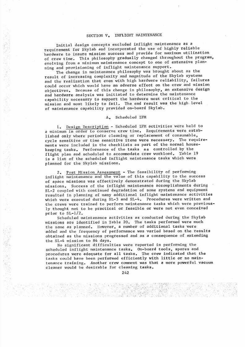
8/8/2019 MSFC Skylab Crew Systems Mission Evaluation
http://slidepdf.com/reader/full/msfc-skylab-crew-systems-mission-evaluation 266/397
_
SECTIONV. INFLIGHTMAINTENANCE
Initial design concepts excluded inflight maintenance as a
requirement for Skylab and incorporated the use of highly reliablehardware to insure mission success and provide for maximum utilization
of crew time. This philosophy gradually changed throughout the program,
evolving from a minimum maintenance concept to one of extensive plan-
ning and provisioning of inflight maintenance support.
The change in maintenance philosophy was brought about as the
result of increasing complexity and magnitude of the Skylab systems
and the realization that even with high hardware reliability, failures
could occur which would have an adverse effect on the crew and mission
objectives. Because of this change in philosophy, an extensive designand hardware analysis was initiated to determine the maintenance
capability necessary to support the hardware most critical to the
mission and most likely to fail. The end result was the high level
of maintenance capability provided on-board Skylab.
A. Scheduled IFM
i. Design Description - Scheduled IFM activities were held toa minimum in order to conserve crew time. Requirements were estab-
lished only where periodic cleaning or replacement of consumable,
cycle sensitive or time sensitive items were necessary. The require-ments were included in the checklists as part of the normal house-
keeping tasks. Performance of the tasks as controlled by the
flight plan and scheduled to accommodate crew workload. Table 19is a list of the scheduled inflight maintenance tasks which were
planned for the Skylab missions.
2. Post Mission Assessment - The feasibility of performing
inflight maintenance and the value of this capability to the success
of space missions was effectively demonstrated during the Skylab
missions. Success of the inflight maintenance accomplishments during
SL-2 coupled with continued degradation of some systems and equipment
resulted in planning of many additional inflight maintenance activities
which were executed during SL-3 and SL-4. Procedures were written and
the crews were trained to perform maintenance tasks which were previous-
ly thought not to be practical or feasible or were not even conceived
prior to SL-I/2.Scheduled maintenance activities as conducted during the Skylab
missions are identified in Table 20. The tasks performed were much
the same as planned. However, a number of additional tasks were
added and the frequency of performance was varied based on the results
obtained as the missions progressed and as a consequence of extending
the SL-4 mission to 84 days.
No significant difficulties weme reported in performing thescheduled inflight maintenance tasks. On-board tools, spares and
procedures were adequate for all tasks. The crew indicated that thetasks could have been performed efficiently with little or no main-
tenance training. Another crew comment was that a more powerful vacuum
cleaner would be desirable for cleaning tasks.
242
ii iii i i i!ii!!!
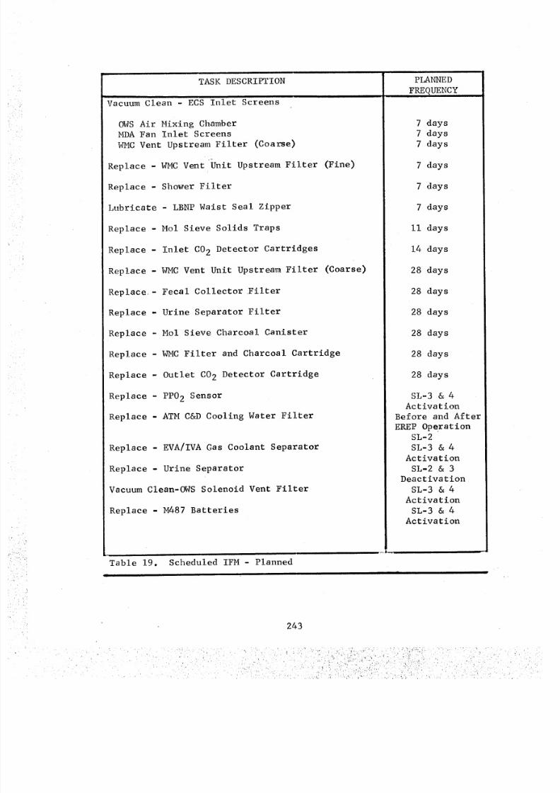
8/8/2019 MSFC Skylab Crew Systems Mission Evaluation
http://slidepdf.com/reader/full/msfc-skylab-crew-systems-mission-evaluation 267/397
TASK DESCRIPTION
Vacuum Clean - ECS Inlet Screens
OWS Air Mixing ChamberMDA Fan Inlet Screens
WMC Vent Upstream Filter (Coarse)
Replace - WMC VentUnit Upstream Filter (Fine)
Replace - Shower Filter
Lubricate - LBNP Waist Seal Zipper
Replace - Mol Sieve Solids Traps
Replace - Inlet C02 Detector Cartridges
Replace - WMC Vent Unit Upstream Filter (Coarse)
Replace.- Fecal Collector .Filter
Replace - Urine Separator Filter
Replace - Mol Sieve Charcoal Canister
Replace - WMC Filter and Charcoal Cartridge
Replace - Outlet CO 2 Detector Cartridge
Replace - PP02 Sensor
Replace - ATM C&D Cooling Water Filter
Replace - EVA/IVA Gas Coolant Separator
Replace - Urine Separator
Vacuum Clean-OWS Solenoid Vent Filter
Replace - M487 Batteries
Table 19. Scheduled IFM - Planned
w
PLANNED
FREQUENCY
7 days
7 days
7 days
7 days
7 days
7 days
ii days
14 days
28 days
28 days
28 days
28 days
28 days
28 days
SL-3 & 4
Activation
Before and After
EREP OperationSL-2
SL-3 & 4
Activation
SL-2 & 3
Deactivation
SL-3 & 4
Activation
SL-3 & 4
Activation
243
i./_ ,_
8/8/2019 MSFC Skylab Crew Systems Mission Evaluation
http://slidepdf.com/reader/full/msfc-skylab-crew-systems-mission-evaluation 268/397
: i! iiil 41 / iiiil/!il} i!!ii! ii}ii
_o
TASK DESCRIPTION
Vacuum Clean - OWS Heat Exchanger Vanes
Vacuum Clean - ECS Inlet Screens
OWS Air Mixing Chamber
OWS Heat Exchanger FansMDA Fans
AM Circulating FansWMC Debris Coarse Filter
WMC Debris Coarse/Fine FilterWMC Debris Fine Filter
Replace - WMC Vent Unit Fine Filter
Replace - Shower Filter
Replace - Mol Sieve Solids Traps
Replace - Inlet C02 Detector CartridgesReplace - WMC Vent Fine/Coarse Filters
Replace - Fecal Collector Filter
Replace - Urine Separator Filter
Replace - Mol Sieve Charcoal CanisterReplace - WMC Filter and Charcoal Cartridge
Replace - Outlet C02 Detector Cartridge
Replace - PP0 2 Sensor
Replace - ATM C&D Cooling Water Filter
Replace - EVA/IVA Gas Coolant Separator
Replace - Urine Separator
Vacuum Clean - OWS Solenoid Vent Filter
PLANNED
FREQUENCY
7 days
7 days
7 days.
7 days
7 days
7 days
Ii days
14 days
28 days
28 days
28 days
28 days
28 days
28 daysSL-3 & 4
Activation
Before &
After EREP
OperationSL-2SL-3 & 4
Activation
SL-2 & 3
Deactiv-
ation
SL-3 & 4
Activation
Table 20. Scheduled IFM - Conducted
SL-2
FREQUENCY
7 days
7 days7 days
7 days
7 days
7 days
SL-3
FREQUENCY
3 days
3 days3 days
3 days
3 days
12 days
SL-4
FREQUENCY
6 days
2 days
2 days2 days
2 days
2 days
12 days
Following Crew Showers
II days II days I II days
14 daysOn MD-28
28 days
28 daysOn MD-28
28 days
On MD-4
On MD-25
Deactiv-
ation
14 daysOn MD-59
28 days
28 daysOn MD-59
28 daysActivation
on MD-58
Deactiv-
ation
A ctiva t ioni
14 daysOn MD-28
28 days
28 daysOn MD-27
28 daysActivation
On MD-50
Activation
8/8/2019 MSFC Skylab Crew Systems Mission Evaluation
http://slidepdf.com/reader/full/msfc-skylab-crew-systems-mission-evaluation 269/397
B. Unscheduled IFM
i. Design Description - Unscheduled IFM capability was provided
on board the SWS for the purpose of replacing failed components,
installing auxillary and backup hardware, and equipment servicing and
repair. This capability was provided in the form of spares, tools andprocedures for performing 160 different unscheduled tasks. Thesetasks are listed in Table 21.
Skylab crews performed many unscheduled maintenance tasks during
the three missions. These were anticipated tasks for which on-board
tools, spares and procedures had been provided on SL-I. The crew
had been trained to perform each of the tasks;and the checklists
containing the required procedures were available in the flight data
file. Table 22 is a listing of the unscheduled maintenance tasks
accomplished during the missions.
2. SL-2 Activities
a. M074 Specimen Mass Measuring Device (SMMD) Electronics
Module Replacement - On MD-9 (DOY 153), the M074 Electronics Modulefrom the Wardroom SMMD was removed and reinstalled in the WMC SMMD.
The changeout was a result of an earlier failure of the WMC unit and
was a pre-planned IFM capability to provide an interim solution for
the specific failure which occurred. Per the IFM planning, a spare
Electronics Module was carried up and installed during SL-3.
b. Color TV Camera Replacement - Failure of the Color TV
Camera on MD-IO (DOY-154) required use of the spare camera for theremainder of the mission. The crew disassembled the camera in an
attempt to repair it, but determined it was not repairable.
c. Urine Separator Filter Replacement - Hydrophobic filter
was replaced in the CDRs Urine separator during MD-12 (DOY 156).
This filter was scheduled to be replaced after the first 28 days
of SL-3 and SL-4. The filters were also changed out at the end of
each mission as an integral part of the Urine Separators. The
unscheduled replacement of the filter reduced the number of spares
available to support SL-3 and SL-4 to 5 units. Six spares were
required to perform the scheduled replacements. As a result, it was
necessary to eliminate one of the mid-mission replacement requirements.
d. Manual Opening of S054 Aperture Door - Release pins were
incorporated into the design of the ATM aperture doors to provide the
capability for manually opening and restraining any of the individual
aperture doors during EVA in the event that the door drive mechanism
failed. During the MD-14 (DOY 158) EVA, the S054 Aperture Door was
manually opened after a failure in the drive mechanism had occurred.
No problems or difficulties were noted in performing this activity.
245
8/8/2019 MSFC Skylab Crew Systems Mission Evaluation
http://slidepdf.com/reader/full/msfc-skylab-crew-systems-mission-evaluation 270/397
_o
o_
TASK DESCRIPTION
SPARES
Replace-TV MonitorReplace-TV Camera/Monitor Cable
Replace-TV Power Cable
Replace-OWS ECS FlowmeterTransducer
Install-IFM Contingency TV SystemCables
RF Cable Assy. -009
RF Cable Assy. -010
RF Cable Assy. -019
RF Cable Assy. -020
Replace-Communications CarrierInstall-Command Transfer Unit
Replace-MDA No. 2 Control Umbilica
Water SystemReplace-WMC Hot Water Dispenser
Replace-Drinking Water Dispenser
Replace-Food Reconstitution Water
Dispenser Valve
Replace-Flush Water Dispenser
Replace-Water System QD-615
Quick Disconnect Coupling
0-Ring
Replace-Water System QD-631
Replace-Wardroom Water Hose
Replace-Water System Sample
Port QD O-Ring
NOTE: Number in parenthesis indic_
ON-BOARD
SPARES
I
I
I
0(i)
o(1)o(I)o(i)o(i)3
I
I
I
I
I
I
i
3
I
I
TASK DESCRIPTION
SPARES
Service/Deservice-Cluster Water
SystemsLSU/PCU
ATM C&D Coolant Loop
Suit Umbilical System
Replace-Wardroom Water Heater
Replace-WMC Water Heater
Replace-Wardroom Water HeaterWith WMC Water Heater
Replace-Food Reconst itut ion
Water Dispenser 0-Ring
0-Ring -5030-Ring -511
Electrical System
Replace-Sl90 Window Heating ControlUnit
Replace-Sl90 Window Heater CableReplace-AM Light Bulb (20 Watt)
Replace-AM Light Bulb (I0 Watt)
Replace-MDA/OWS GeneralIl lumin ati on Flood light
Replace-MDA Power Umbilical
Ins ta lI-MDA /CSM Con tinge ncyPower Cable
Replace-Urine Separator Cable Assy
i
_es spares available on ground for resupply! J
ON-BOARD
SPARES
N/A
N/A
N/AI
i
N/A
0(1)
o(I)24
120
6(6)
Table 21. Unscheduled IFM - 3 of 5!
8/8/2019 MSFC Skylab Crew Systems Mission Evaluation
http://slidepdf.com/reader/full/msfc-skylab-crew-systems-mission-evaluation 271/397
_O
TASK DESCRIPTION
SPARES
WASTE MANAGEMENT SYSTEM
Replace-Waste Management UnitPower Module
-Vacuum Cleaner Power
Module
-Shower Power Module
-Suit Drying StationPower Module
Replace-Dump Probe Assy.
Replace-Trash Airlock InboardHatch Seal
Replace-Trash Airlock Torsion BarSeal
0-Ring - 1
O-Ring - 501
Replace- Trash Airlock Pressure
Gauge Seal
O-Ring-509
0-Ring-511
Release-Jammed Trash Airlock
Ejector
Clean-Trash Airlock Vent Valve
Filter
ON -B OARD
SPARES
1
4
2
N/A
N/A
NOTE: Number in parenthesis indicates quantitI
Table 21. Unscheduled IFM - 1 of 5
TASK DEscRIPTION
SPARES
Replace-Trash Airlock Vent Valve
0-Ring/Plug Subassy.
Replace-Waste Processor Door
Seal (Quad-X-seal)Replace-Waste Processor Control
Panel
Replace-Washcloth Squeezer Bal-Seal
Replace-Washcloth Squeezer Flappervalve
Replace-Urine Separator
Replace-Urine Separator Dump LineFlex Hose
Replace-Urine Separator Motor-Shower Separator Motor
Replace-Urine Separator Cover Seal
Replace-Urine Separator Support
and Filter (Scheduled Mainten-
ance Spares)
Replace-Waste Processor Screen
Replace-Fecal Collector Bellows 1
Replace-Waste Processor Pressure 1Mechanism
Replace-Fecal Collector Liner 1
Replace-Waste Processor Filter 2
Saver Valve 0-Ring
Replace-Urine Separator Air 1
Return Hose (Molded)of spares available on ground for resupply
t I
ON-BOARD
SPARES
1
3
i
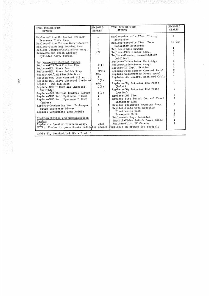
8/8/2019 MSFC Skylab Crew Systems Mission Evaluation
http://slidepdf.com/reader/full/msfc-skylab-crew-systems-mission-evaluation 272/397
• • • •i!il !!ii !!!!!iiiiili!iiii!i!!i!! iiii¢ •••ii?iillIII!!
_o
Oo
TASK DESCRIPTION
SPARES
Replace-Urine Collector DrainerPressure Plate Assy.
Replace-Urine Volume Determinator
Replace-Urine Bag Housing Assy.
Replace-Crimper/Cutter/Door Assy.Remove/Clean-Trash Airlock
Cylinder Assy. Screen
3N-BOARD
SPARES
i
I
i
N/A
Environmental Control System
Replace-ECS Ventilation Fan 8(1)
Replace-MOL Sieve Fan I
Replace-MOL Sieve Solids Trap 2Pair
Repair-MDA/CSM Flexible Duct N/A
Replace-WMC Odor Control Filter I
Replace-MOL Sieve Charcoal Caniste_ 0(2)Repair - OWS ECS Duct 1 N/A
Replace-WMC Filter and Charcoal i 0(I)
Cartridge I
Replace-OWS Thermal Control Heater I(i)Replace-WMC Vent Upstream Filter i I
Replace-WMC Vent Upstream Filter i I
(Inner) !!
Replace-Condensing Heat Exchanger
Water Separator Plates
Replace-Condensate Tank Module
4
I
Instrumentation and Communication
Replace - Speaker Intercom Assy. 2(2)
NOTE: Number in parenthesis indicates spares available on ground for resupplyI I
Table 21. Unscheduled IFM - 2 of 5
!
TASK DESCRIPTION ON-BOARD
SPARES SPARES
Replace-Portable Timer Timing 4
Batteries
Replace-Portable Timer Tone 12(24)
Generator Batteries
Replace-Video Switch I
Replace-Fire Sensor Assy. 6
Replace-Crewman Communication 2
Umbilical
Replace-Teleprinter Cartridge I
Replace-Teleprinter Assy. I
Replace-TV Input Station I
Replace-Fire Sensor Control Panel 2
Replace-Teleprinter Paper spool i
Replace-LCC Control Head and Cable I
Assy.
Replace-C02 Detector End Plate I
(Inlet)
Replace-C02 Detector End Plate I
(Outlet)
Replace-GMT Timer IReplace-Fire Sensor Control Panel 8
Indicator LampReplace-Dosimeter Mounting Assy. I
Replace-Video Tape RecorderElectronics Unit i
Transport Unit i
Replace-AMTape Recorder 4Install-Video Switch Power Cable I
Replace-Color TV Camera I
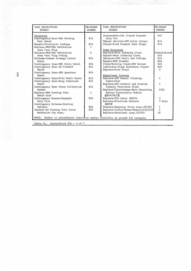
8/8/2019 MSFC Skylab Crew Systems Mission Evaluation
http://slidepdf.com/reader/full/msfc-skylab-crew-systems-mission-evaluation 273/397
• ,...... -
- i <-j% [- =" _] .-5.-- >- ..'
TASK DESCRIPTION
SPARE S
Structure
Contingency/Open-MDA DockingPort Hatch
Repair-Structural Leakage
Replace- OW S/M DA Habi tat ion
Area Vent Plug
Replace- OW S/M DA Habi tat ion
Area Vent Plug 0-RingRelease-Jammed Stowage Locker
Doors
Contingency Open-OWS Entry Hatch
Contingency Open AM ForwardHatch
Contingency Open-ATM ApertureDoors
Contingency Open-Film Vault Doors
Contingency Open-Ring ContainerDoors
Contingency Open Urine CollectionDrawer
Replace-MDA Docking PortHatch Seal
Contingency Remove-Expando
Grip Pins
Contingency Release-DockingLatches
Install-AMViewing Port Cover
Mechanism Cap Assy.
ON-BOARD
SPARES
N/A
N/A1
4
N/A
N/AN/A
N/A
N/AN/A
N/A
1
N/A
N/A
N/A
TASK DESCRIPTION
SPARES
Disassemble-SAL Tripod Expando
Grip Pin
Manual Decinch-ATM Solar Arrays
Adjust-Food Freezer Door Hinge
Crew EquipmentReplace-Shoe Indexing Cleat
Repair-Shoe Indexing Cleat
Maintain-EMU Seals and 0-Rings
Repair-EMU Bladder
Clean/Antifog Treat-EMUHelmet
Lubricate-Sleep Restraint Zipper
Replace-Food Trays
Experiment SystemsReplace-ATMManual Pointing
Controller
Replace-ATM Control and DisplayConsole Precision Clock
Replace/Interchange-Mass Measuring
Device Electronics Module(M074/MI7_
Replace-VCG Cable (M093)
Replace-Electrode Harness(M09_
Replace-Magazine Drive Assy.(Sl90)
Replace-Cooler/Dewar/Detector(S192)
Rep lace-Dess icant Assy.(Sl90)
NOTE: Number in parenthesis indic_ :es spares available on ground for resupply
Table 21. Unscheduled IFM - 4 of 5
ON -BOARD
SPARESi i
N/A
N/A
N/A
Cannibalized
N/A
N/A
N/A
N/A
N/A
2
I
I
0(I)
3
3 Kits
I
I
18
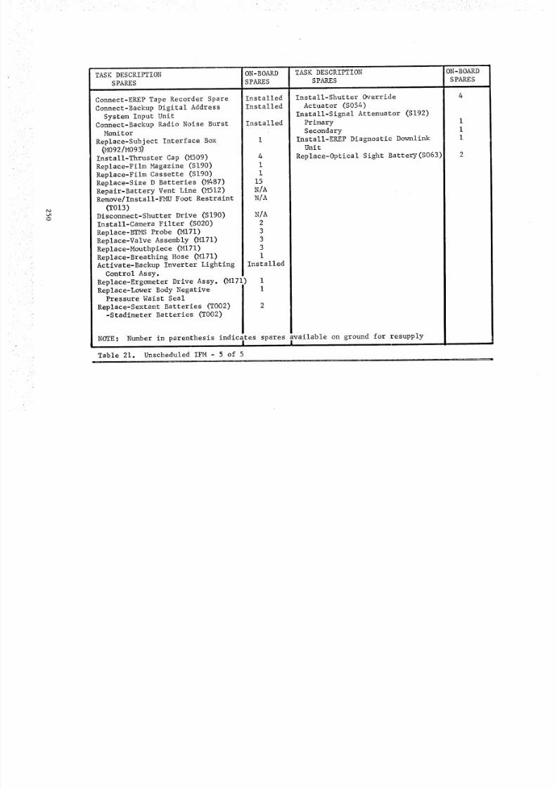
8/8/2019 MSFC Skylab Crew Systems Mission Evaluation
http://slidepdf.com/reader/full/msfc-skylab-crew-systems-mission-evaluation 274/397
_O
o
TASK DESCRIPTION
SPARES
Connect-EREP Tape Recorder Spare
Connect-Backup Digital Address
System Input UnitConnect-Backup Radio Noise Burst
MonitorReplace-Subject Interface Box
(M092/M09_Install-Thruster Cap (M509)
Replace-Film Magazine (S190)
Replace-Film Cassette (S190)
Replace-Size D Batteries (M487)
Repair-Battery Vent Line (M512)Remove/Install-FMUFoot Restraint
(T013)Disconnect-Shutter Drive (S190)
Install-Camera Filter (S020)
Replace-BTMS Probe (MI71)
Replace-Valve Assembly (MI71)
Replace-Mouthpiece (MI71)
Replace-Breathing Hose (MI71)Activate-Backup Inverter Lighting
Control Assy.
Replace-Ergometer Drive Assy. (MI71)i
Replace-Lower Body NegativePressure Waist Seal
Replace-Sextant Batteries (T002)-Stadimeter Batteries (T002)
ON-BOARD
SPARES
Installed
Installed
Installed
4
I
I
15
N/A
N/A
N/A
2
3
3
3
I
Installed
TASK DESCRIPTION
SPARES
Install-Shutter Override
Actuator (S054)
Install-Signal Attenuator (S192)
Primary
Secondary
Install-EREP Diagnostic DownlinkUnit
Replace-Optical Sight Battery(S063)
NOTE: Number in parenthesis indicates spares available on ground for resupply! !
Table 21. Unscheduled IFM - 5 of 5
ON-BOARD
SPARES
I
i
I
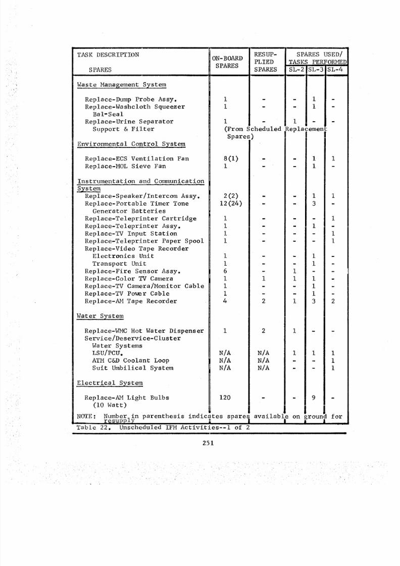
8/8/2019 MSFC Skylab Crew Systems Mission Evaluation
http://slidepdf.com/reader/full/msfc-skylab-crew-systems-mission-evaluation 275/397
TASKDESCRIPTION
SPARES
Waste Management System
Replace-Dump Probe Assy.
Replace-Washcloth SqueezerBal-Seal
Replace-Urine Separator
Support & Filter
Environmental Control System
Replace-ECS Ventilation Fan
Replace-MOL Sieve Fan
Instrumentation and Communication
s_ze aReplace-Speaker/Intercom Assy.
Replace-Portable Timer Tone
Generator Batteries
Replace-Teleprinter Cartridge
Replace-Teleprinter Assy.
Replace-TV Input Station
Replace-Teleprinter Paper Spool
Replace-Video Tape RecorderElectronics Unit
Transport Unit
Replace-Fire Sensor Assy.
Replace-Color TV CameraReplace-TV Camera onitor Cable
Replace-TV Power Cable
Replace-AM Tape Recorder
Water Syste m
Replace-_MC Hot Water Dispenser
Service/Deservice-Cluster
Water SystemsLSU/PCU.
ATM C&D Coolant Loop
Suit Umbilical System
Electrical System
ON- BOARD
SPARES
Replace-AMLight Bulbs
(I0 Watt)
RESUP-
PLIED
S PARE S
(From Scheduled
Spares)
8(l)i
2(2)
12(24) -
1
1
i
1
I
i
6
I Ii
1
4 2
I 2
N/A N/A
N/A N/A
N/A N/A
SPARES USED/
TASKS PERFORMED
SL-2[ JSL-3 SL-4
I
m
Replacementir
- 1 i
- 1 -
- 1 i
- 3 -
- - 1
- 1 -
- - 1
- - 1
- 1 -
- i
1 - -
1 I -- I
- i
i 3 2
i i " -
1 i i
- - 1
- - 1
120 - - 9 -
NOTE: Number_ in parenthesis indicates spares available on ground forr_supply _ I I i |
Table 22. Unscheduled IFM Activities--I of 2
251
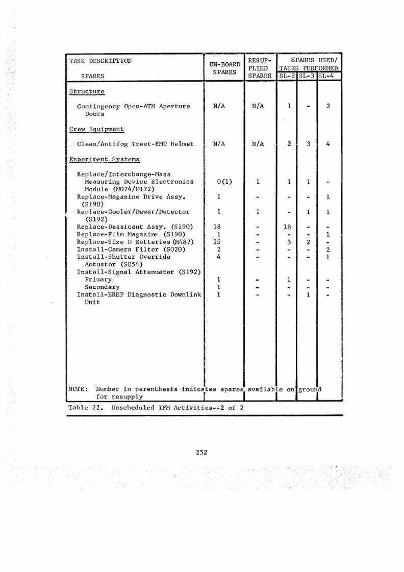
8/8/2019 MSFC Skylab Crew Systems Mission Evaluation
http://slidepdf.com/reader/full/msfc-skylab-crew-systems-mission-evaluation 276/397
TASKDESCRIPTION
SPARES
Structure
Contingency Open-ATM ApertureDoors
Crew Equipment
ON-BOARD
SPARES
N/A
Clean/Antifog Treat-EMU Helmet N/A
Experiment Systems
Replace nterchange-Mass
Measuring Device Electronics 0(i) i
Module (MO74/MI72)Replace-Magazine Drive Assy. I -
(S190)
Replace-Cooler/Dewar/Detector I i
(S192)
Replace-Dessicant Assy. (S190) 18 -
Replace-Film Magazine (S190) I -
Replace-Size D Batteries(M487) 15 -
Install-Camera Filter (S020) 2 -Install-Shutter Override 4 -
Actuator (S054)
Install-Signal Attenuator (S192)
Primary I -
Secondary I -
Install-EREP Diagnostic Downlink i
Unit
RESUP- SPARES USED/
PLIED TASKS PERFORMED
SPARES SL-2 SL-3 SL-4
N/A i - 2
N/A 2 3 4
I i -
- i i
18 - -
- - 1
3 2 -
- - 2
- - 1
1 - -
i
- 1 -
NOTE: Number in parenthesis indicates spares available on ground
for resupply i
Table 22. Unscheduled IFM Activities--2 of 2
252
i L •
8/8/2019 MSFC Skylab Crew Systems Mission Evaluation
http://slidepdf.com/reader/full/msfc-skylab-crew-systems-mission-evaluation 277/397
e. AM Tape Recorder Replacements - AM Tape Recorder No. 1
failure was reported after completion of the trouble-shooting proce-
dure on MD-15 (DOY) 159). The recorder was replaced with one of the
four spares provided for unscheduled IFM support of the three AM
Tape Recorders. On MD-29 (DOY 173), a second recorder failure was
reported after splashdown. The second recorder was replaced by theSL-3 crew. Two additional spares were flown on SL-3 to replenish the
units expended during SL-2.
f. S190 Desiccant Replacement - Six S190 desiccant units
were replaced in the S190 camera assembly on MD-17 (DOY 161) due to
evidence of possible moisture contamination in the camera assembly.
A total of 18 spare desiccant units were provided on-board for unsche-
duled replacements. The CDR noted that the color of the removed units
was the same color as the new units installed. The replaced units
were baked out in the waste processor to remove all the moisture and
to insure thoroughly dry units would be available. All 18 of the
spares were alternately installed, removed and baked out throughout
the missions.
g. Fire Sensor Control Panel Replacement - Failure of Fire
Sensor Control Panel 392 in the AM was confirmed on MD-17 (DOY 161).
The panel was replaced with one of the two spares on-board. The
failure involved only the Fire Sensor No. 2 circuit. Two panels in
the OWS use only the Fire Sensor No. 1 circuit. Consequently, the
failed panel was retained for further use as a spare.
h. WMC Water Dispenser Valve Replacement - Replacement of
the WMC Water Dispenser Valve was necessary when the valve became
plugged. The one on-board spare was installed on MD-22 (DOY 166).
Two additional spares were provided on SL-3 to insure adequate water
supply in the WMC. The failed unit was returned on SL-2 in order to_etermine the exact nature of the failure.
3. SL-3 Activities
a. M074 Electronics Module Replacement - The wardroom SMMD
Electronics Module was moved to the WMC SMMD during SL-2. A replace-
ment unit was supplied on SL-3 and installed during activation.
b. AM Tape Recorder Replacement - Three AM Tape Recorders
were replaced during SL-3. On MD-4 (DOY 212) a recorder, which failed
after SL-2 deactivation, was replaced. A second failed recorder was
replaced on MD-48 (DOY 256). A third recorder was replaced on MD-52(DOY 260) because the remaining recorder had exceeded its operating
life limitation. Four spare recorders were initially launched on SL-I
and two additional spares were provided on SL-3.
253
8/8/2019 MSFC Skylab Crew Systems Mission Evaluation
http://slidepdf.com/reader/full/msfc-skylab-crew-systems-mission-evaluation 278/397
c. EREPDownlink Unit Installation - The EREPDownlink Unitwas installed on MD-6 (DOY214). This maintenance activity involvedinstallation of auxiliary hardware and was not the result of a failure.The Downlink Unit provided capability of patching between EREPand thevideo system to provide direct down link of data from EREPto ground.
d. Video Tape Recorder Replacement- Replacement of theVideo Tape Recorder was accomplished on MD-II (DOY 219) after failure
of a circuit board occurred in the electronics unit. All necessary
tools, spares and procedures were available on-board to perform this
task. During the replacement operation a faulty 3/16-in. allen bit
was discovered and was replaced with a spare from the spare tool
inventory on-board.
e. Teleprinter Replacement - Failure of a drive roller in
the Teleprinter head assembly resulted in replacement of the Tele-
printer. The replacement was performed on MD-II (DOY 219). Only one
spare Teleprinter was provided and as a result procedures were devel-oped for repair of the failed unit using on-board materials in the
event a second failure occurred on SL-3. A teleprinter repair kit
was developed for SL-4 and included replacements for the failed parts.
f. Mol Sieve Fan Replacement - On MD-12 (DOY 220) one of
the two fans in Mol Sieve B was replaced. The failure was isolated
to the fan after a malfunction procedure was performed on the Mol
Sieve. One spare fan was provided on-board to support the four
fans installed in the two Mol Sieves.
g. STS Light Bulbs Replacement - Three lO-watt light bulbs
in the STS were replaced on MD-12 (DOY 221). A total of twenty-four
20-watt and one hundred twenty 10-watt spare bulbs were provided in
the AM. These were incandenscent, bayonet base bulbs. Tools were
not required for replacement. A total of nine of the 10-watt bulbs
were replaced during the mission. No 20-watt bulb usage was reported.
h. Speaker Intercom Assembly Replacement - The Speaker
Intercom Assembly located at the -Z SAL (PNL-540) was replaced on MD22
(DOY 230) as a result of an apparent failure of the "push to talk"
switch. Two spare units were provided on-board.
i. TV Camera Replacement - The malfunction procedure
performed on the video system resulted in identification of a failed
TV camera. The camera was replaced on MD 28 (DOY 236) with the spareprovided on-board. One camera was returned at the end of SL-3 and a
new camera was provided on SL-4.
j. Condensate Dump Probe Replacement - The problemassociated with dumping condensate into the waste tank was isolated
to the dump probe. Suspected heater failure resulted in replacement
of the probe on MD-36 (DOY 244) and an accumulation of ice was found
in the probe.
254
8/8/2019 MSFC Skylab Crew Systems Mission Evaluation
http://slidepdf.com/reader/full/msfc-skylab-crew-systems-mission-evaluation 279/397
k. TV PowerCable Replacement - The TV Power Cable wasreplaced on MD48 (DOY256) after s malfunction procedure was performed
on the video system to determine the cause of noise generated in the
system. One spare cable was provided on-board. Later investigation
by the crew revealed an open in the center conductor of the coaxialcable.
i. Washcloth Squeezer Bal--Seal Replacement - Leakage of
the Washcloth Squeezer resulted in replacement of the squeezer plunger
seal (BsI-Seal) on MD 56 (DOY 264) with the spare seal provided
on-board. The seal had apparently folded back after striking the
edge of the cylinder during operation. Procedures were developed for
removing contamination which had collected around the piston and
shaft and may have caused seal damage.
m. TV Monitor Cable Replacement - The spare TV Monitor
Cable was installed on MD 56 (DOY 264). Failure was detected when
the crew was unable to acquire a picture on the TV Monitor. The
problem reoccurred when the spare monitor was connected. The causewas finally isolated to the cable when it was flexed at the camera
connector and produced an intermittent picture.
4. SL-4 Activities
a. Manual Opening of the Ha 2 Door - The Ha 2 door on the
sun end of the ATM was pinned open during the EVA performed on M_D 7
(DOY 326). The door was designed with a pin whichjwhen removed,permitted manual opening the door and latching it in the open position.
Excessive drag in the door mechanism made it necessary to perform
this activity.
b. Speaker Intercom Replacement - On M_ 15 (DOY 334) the
Speaker Intercom Assembly located in the MDA, Panel 131, was replaced
as a result of failure of the channel select switch. The failure
occurred in the Channel B position. The second of the two on-board
spares was used for this task.
c. Teleprinter Cartridge and Paper Spool Replacement - The
spare Teleprinter Cartridge and spare Paper Spool were used to correct
an apparent failure of the Teleprinter on MD 19 (DOY 338). The
failure was resolved after it was determined that the paper wasimproperly loaded in the Teleprinter.
d. Manual Pinning of the S082A Door - Failure of the S082Adoor to respond to open/close commands on several occasions made it
necessary to manually latch the door open during the EVA on MD 40
(DOY 359). The S082A door is located on the sun end of the ATM. The
capability to latch the door open was _ feature incorporated into thedesign of the door mechanism.
255
8/8/2019 MSFC Skylab Crew Systems Mission Evaluation
http://slidepdf.com/reader/full/msfc-skylab-crew-systems-mission-evaluation 280/397
e. S054 Shutter Override Actuator Installation - The S054Shutter Override Actuator was installed on MD40 (DOY359) duringthe EVAoperations in order to perform the S054malfunction proceduresand aid in the contingency task to manually position the filter wheel.
The Shutter Override Actuator was launched on-board SL-I.f. SUSLoop Servicing - Servicing of the Suit Umbilical
System was accomplished on MD43 (DOY362) after a low reservoirlevel had been detected. All necessary equipment and procedures wereavailable on-board for this task. The low level in the reservoir was
determined to be the result of coolant loss into the LSU/PCU's which
had not been serviced prior to the first SL-4 EVA.
g. TV Input Station Replacement - A failed TV Input Station
at location 642 in the OWS was replaced on MD 45 (DOY 364). One
spare unit was provided in the MDA for inflight maintenance support
of the TV system. Replacement was required because of a broken pin
in connector J-3.
h. ATM C&D Coolant Loop Servicing - Low coolant level in
the ATM C&D Coolant Loop Reservoir resulted in servicing the system
with water from the OWS on MD 50 (DOY 004). Equipment and procedures
were available on-board to accomplish this task. Replacement of the
ATM C&D Coolant Loop Filter was accomplished in conjunction with the
servicing activity.
i. S190 Magazine Drive Replacement - The spare S190 Magazine
Drive was installed on MD 57 (DOY 011) after the installed assembly
failed. The spare assembly and the necessary tools were provided on
SL-I.
j. S192 Mark XV Detector Replacement - On MD 61 (DOY 015)the S192 Cooler/Detector/Preamp was replaced with a unit which was
launched on SL-4. Replacement of the detector was necessary for proper
alignment and to insure acquisition of accurate data, Malfunction orout of tolerance condition was indicated on the EREP C&D Panel. One
spare was initially launched on SL-I along with the necessary tools
required for installation but the spare was not used.
k. OWS Heat Exchanger Fan Replacement - On MD 63 (DOY 017)
one of the four OWS Heat Exchanger Fans was replaced in an attempt
to correct a degraded airflow condition through the heat exchanger.
This was accomplished in conjunction with vacuum cleaning of the
heat exchanger vanes. An acceptable flowrate resulted from this
activity. The crew modified the vacuum cleaner adapter with card-
board, tape and mosite in order to adequately vacuum the heat exchanger
vanes,
256
8/8/2019 MSFC Skylab Crew Systems Mission Evaluation
http://slidepdf.com/reader/full/msfc-skylab-crew-systems-mission-evaluation 281/397
I. AM Tape Recorder Replacement - AM Tape Recorder No. 3
was replaced on MD 66 (DOY 020) with one of the two remaining spares.
The recorder was replaced because it had exceeded the i000 hour life
limitation. At the time of replacement the unit was still operating
and had 1,579 operating hours in flight and 241 operating hours during
ground test. AM Tape Recorder No. 2 failed on MD 67 (DOY 021) andwas replaced with the remaining spare on-board. The failure occurred
after 1446 operating hours. Two resupply spares were provided on SL-3
and an AM Tape Recorder Repair Kit was launched on SL-4. The repair
kit was not used during SL-4.
5. Post Mission Assessment - No significant problems associated
with unscheduled maintenance were reported by the crew. Tools, spares,
and procedures were adequate for performing all of the required tasks.
257
8/8/2019 MSFC Skylab Crew Systems Mission Evaluation
http://slidepdf.com/reader/full/msfc-skylab-crew-systems-mission-evaluation 282/397
C. Contingency IFM
i. Design Description - In addition to the capability providedfor scheduled and unscheduled inflight maintenance, tools and materials
were placed on-board Skylab to provide a general maintenance capabil-
ity. This capability was provided to permit repair of failed equip-ment for which no specific inflight maintenance activity was antici-
pated. Items such as tape, wire, "C" clamps, various types of pliers,
a vise, twine, hammers and tweezers were included in the Skylab tool
inventory for this purpose.Additional maintenance tools and equipment were launched on-board
the three CSM's to provide capability to correct equipment malfunctions
which were unanticipated. These were tasks for which on-board main-
tenance support was inadequate. Other contingencies developed during
the missions which required maintenance action using the on-board
support equipment but for which procedures had to be developed real
time and uplinked to the crew.
2. SL-2 Activities
a. Skylab Parasol Deployment _ Following launch and orbit
achievement of SL-I, flight data revealed that an apparent failure
of the meteoroid shield had occurred. On SL-2, MD 2 (DOY 146) the
crew successfully deployed a parasol sun shield from the OWS solar
SAL in order to lower the OWS temperature and make the SWS habitable.
The parasol was designed and fabricated following the meteoroid
shield failure and carried up on SL-2.
b. S019 Extension Mechanism Repair - Jamming of the
Articulating Mirror Tilt Gear mechanism resulted in a disassembly
task on MD 7 (DOY 151) involving the use of on-board tools to free
the jammed drive gears. Jamming was caused by a metal tab which was
interferring with the gears. This condition was corrected by bending
the tab back out of the way.
c. Lubrication of Ergometer Pedals - On MD ii (DOY 155),
the MI71 ergometer pedals were lubricated with the general purpose
lubricant provided in the tool kit. This task was performed to
alleviate squeaking which occurred during operation.
d. OWS SAS Wing Deployment - On DOY 134 telemetry data
indicated that the OWS solar arrays did not deploy. It was postulated
that Wing 2 was completely missing and that Wing i had been jammedand prevented from deploying. The fly-around by the SL-2 crew
verified that Wing 2 was in fact missin_and that Wing I had been
restrained by debris from the failed meteoroid shield. Attempts tofree Wing I during a standup EVA from the CSM were unsuccessful.
258
• i L /
8/8/2019 MSFC Skylab Crew Systems Mission Evaluation
http://slidepdf.com/reader/full/msfc-skylab-crew-systems-mission-evaluation 283/397
On MD 14 (DOY 158) using tools which were carried up in the SL-2
CSM for the standup EVA and other on-board tools and equipment, the
crew successfully deployed Wing I. Procedures and tools for deploying
the wing were developed at MSFC and verified in the Neutral Buoyancy
Tank. The procedures were then uplinked to the SL-2 crew.
e. T027/S073 Backup Tripod Mounting - Due to differences
in the backup unit which was flown on SL-2, it did not interface
correctly with the mounting provisions in the OWS. On MD 18 (DOY 162),
the tripod was mounted using attaching hardware salvaged from the
throw-away items used as launch restraints and removed during activa-tion. The flight tripod was used to support the parasol at the solar
SAL.
f. CBRM #15 Contingency Procedure - During the EVA on MD
28 (DOY 172), a contingency procedure was successfully performed on
CBRM #15 to free a stuck relay. The procedure, which was developed
by MSFC, consisted of striking the CBRM with a hammer at a pre-
determined location that would impact a maximum impulse to the relay.
3. SL-3 Activities
a. Twin Pole Solar Sail Deployment - The Twin Pole Solar
Sail was deployed during the first SL-3 EVA on MD i0 (DOY 213) over
the top of the Parasol which was deployed during SL-2. The procedure
involved EVA erection of two poles from the ATM center work station
extending to the aft radiator section of the OWS. The sail was then
deployed by means of clothesline ropes attached at the end of each
pole and positioned over the habitation area of the OWS. The two
poles were assembled from 22 specially designed pole sections, each
five feet in length. The sail and all equipment necessary for deploy-ment was launched on-board the SL-2 CSM.
b. S055 Ramp Latch Removal - On MD i0 (DOY 218) the latch
ramp was removed from the S055 aperture door latch mechanism. This
task was accomplished during EVA and involved use of a 7/16-inch
openend/box wrench to remove two bolts securing the _ tch ramp and
shims. Removal of the ramp was necessary to alleviate binding of
the door during opening and closing.
c. AM Tape Recorder Disassembly - AM Tape Recorders were
disassembled on MD 15 and MD 20 (DOY 223 and DOY 228) to determinethe cause of failure. In both instances the failure was isolated to
a worn drive belt. All tools necessary for disassembly were on-board.
d. Mark i Exerciser Repair - On MD 23 (DOY 231) the crew
reported that the _ope on the Mark I Exerciser had broken. Aprocedure was developed on the ground to replace the rope and uplinked
259
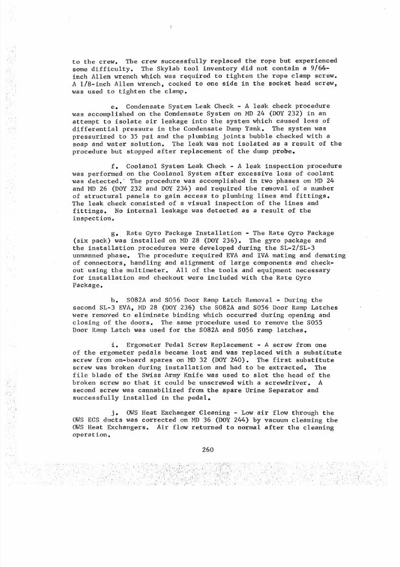
8/8/2019 MSFC Skylab Crew Systems Mission Evaluation
http://slidepdf.com/reader/full/msfc-skylab-crew-systems-mission-evaluation 284/397
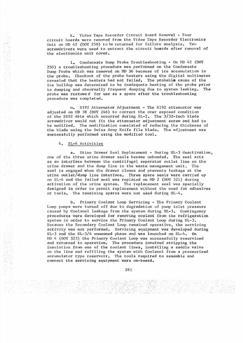
8/8/2019 MSFC Skylab Crew Systems Mission Evaluation
http://slidepdf.com/reader/full/msfc-skylab-crew-systems-mission-evaluation 285/397
k. Video Tape Recorder Circuit Board Removal - Four
circuit boards were removed from the Video Tape Recorder Electronics
Unit on MD 42 (DOY 250) to be returned for failure analysis. Two
screwdrivers were used to extract the circuit boards after removal of
the electronics unit cover.
i° Condensate Dump Probe Troubleshooting - On MD 42 (DOY
250) a troubleshooting procedure was performed on the Condensate
Dump Probe which was removed on MD 36 because of ice accumulation in
the probe. Checkout of the probe heaters using the digital multimeterrevealed that the heaters had not failed. The probabl_ cause of the
ice buildup was determined to be inadequate heating of the probe prior
to dumping and abnormally frequent dumping due to system leaking. The
probe was restowed for use as a spare after the troubleshooting
procedure was completed.
m. S192 Attenuator Adjustment - The S192 attenuator was
adjusted on MD 38 (DOY 246) to correct the over exposed conditionof the S192 data which occurred during SL-2. The 3/32-inch blade
screwdriver would not fit the attenuator adjustment screw and had to
be modified. The modification consisted of reducing the thickness of
the blade using the Swiss Army Knife file blade. The adjustment was
successfully performed using the modified tool.
4. SL-4 Activities
a. Urine Drawer Seal Replacement - During SL-3 deactivation,one of the three urine drawer seals became unbonded. The seal acts
as an interface between the centrifugal separator outlet line on the
urine drawer and the dump line in the waste management unit. The
seal is engaged when the drawer closes and prevents leakage at the
urine outlet/dump line interface. Three spare seals were carried up
on SL-4 and the failed seal was replaced on MD 2 (DOY 321) during
activation of the urine system. The replacement seal was specially
designed in order to permit replacement without the need for adhesives
or tools. The remaining spares were not used during SL-4.
b. Primary Coolant Loop Servicing - The Primary Coolant
Loop pumps were turned off due to degradation of pump inlet pressure
caused by Coolanol leakage from the system during SL-3. Contingency
procedures were developed for removing coolant from the refrigeration
system in order to service the Primary Coolant Loop during SL-3.
Because the Secondary Coolant Loop remained operative, the servicingactivity was not performed. Servicing equipment was developed during
SL-3 and the SL-3/4 unmanned phase and was launched on SL-4. On
_ 4 (DOY 323) the Primary Coolant Loop was successfully reserviced
and returned to operation. The procedure involved stripping the
insulation from one of the coolant lines, installing a saddle valve
on the line and refilling the system with Coolanol from a pressurized
accumulator type reservoir. The tools required to assemble and
connect the servicing equipment were on-board.
261
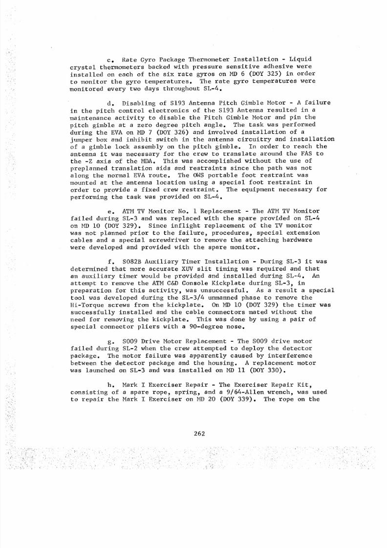
8/8/2019 MSFC Skylab Crew Systems Mission Evaluation
http://slidepdf.com/reader/full/msfc-skylab-crew-systems-mission-evaluation 286/397
c. Rate Gyro PackageThermometerInstallation - Liquidcrystal thermometers backed with pressure sensitive adhesive wereinstalled on each of the six rate gyros on MD6 (DOY325) in orderto monitor the gyro temperatures. The rate gyro temperatures were
monitored every two days throughout SL-4.d. Disabling of S193 Antenna Pitch Gimble Motor - A failure
in the pitch control electronics of the S193 Antenna resulted in amaintenance activity to disable the Pitch Gimble Motor and pin thepitch gimble at a zero degree pitch angle. The task was performedduring the EVA on MD7 (DOY326) and involved installation of ajumper box and inhibit switch in the antenna circuitry and installationof a gimble lock assembly on the pitch gimble. In order to reach theantenna it was necessary for the crew to translate around the FAS tothe -Z axis of the MDA. This was accomplished without the use ofpreplanned translation aids and restraints since the path was notalong the normal EVAroute. The OWSportable foot restraint wasmounted at the antenna location using a special foot restraint inorder to provide a fixed crew restraint. The equipment necessary forperforming the task was provided on SL-4.
e. ATMTV Monitor No. i Replacement - The ATMTV Monitorfailed during SL-3 and was replaced with the spare provided on SL-4on MDi0 (DOY329). Since inflight replacement of the TV monitorwas not planned prior to the failure, procedures, special extensioncables and a special screwdriver to remove the attaching hardwarewere developed and provided with the spare monitor.
f. S082BAuxiliary Timer Installation - During SL-3 it was
determined that more accurate XUVslit timing was required and thatan auxiliary timer would be provid#d and installed during SL-4. An
attempt to remove the ATM C&D Console Kickplate during SL-3, in
preparation for this activity, was unsuccessful. As a result a specialtool was developed during the SL-3/4 unmanned phase to remove the
Hi-Torque screws from the kickplate. On MD I0 (DOY 329) the timer was
successfully installed and the cable connectors mated without the
need for removing the kickplate. This was done by using a pair of
special connector pliers with a 90-degree nose.
g. S009 Drive Motor Replacement - The S009 drive motor
failed during SL-2 when the crew attempted to deploy the detector
package. The motor failure was apparently caused by interference
between the detector package and the housing. A replacement motor
was launched on SL-3 and was installed on MD II (DOY 330).
h. Mark I Exerciser Repair - The Exerciser Repair Kit,
consisting of a spare rope, spring, and a 9/64-Allen wrench, was usedto repair the Mark I Exerciser on _ 20 (DOY 339). The rope on the
262
8/8/2019 MSFC Skylab Crew Systems Mission Evaluation
http://slidepdf.com/reader/full/msfc-skylab-crew-systems-mission-evaluation 287/397
exerciser was broken during SL-3 and had becomeabraded at the ends.A temporary repair was madeduring SL-3 but proper tools and spareswere not available for complete refurbishment. The repair kit was
assembled and launched on SL-4.
i. Liquid/Gas Separator Installation in the ATM C&DCoolant Loop - A drop in pump flowrate in the ATM C&D Console Coolant
Loop was corrected on MD 33 (DOY 352). This action involved temporar-
ily installing one of the spare Liquid/Gas Separators in the coolant
loop to filter out possible contamination and gas bubbles in the
system. The coolant was circulated through the separator which was
installed in place of the system filter. After removing the separator
and installing a replacement ATM C&D Coolant Filter, flowrates of
295 ibs/hr for pump B and 280 ibs/hr for pump C were reported. These
rates were slightly above the nominal rates at which the system had
initially operated. The procedure was repeated with the same success
on MD 50 (DOY 004).
j. S054 Filter Wheel Positioning - A maintenance activity
was performed during the MD 40 (DOY 359) EVA to manually position the
S054 Filter Wheel to the "clear aperture" position (Filter No. 3)
The procedure required working through the open S054 door using an
inspection mirror and flashlight and a long i/8-inch screwdriver. The
mirror and flashlight were used for visual observation while the
screwdriver was used to puncture the filter segments in order to
rotate the filter wheel.
5. Post Mission Assessment - As a result of the contingency
activities performed, the crew recommended that a number of different
tools be provided; including a hacksaw, drill and drill bits, and a
larger screwdriver. The recommendations stem from the problemsassociated with extracting the broken screw from the ergometer pedal.
The need for some type of work bench was also expressed as a
result of the AM tape recorder disassembly and the AMS Tilt Mechanism
repair tasks which were performed. According to the crews' comments
the work bench should include features for holding tools and small
parts as well as the components requiring repair or disassembly.It was also suggested that the work bench be insulated so that
electrical checkout and repair of components could be conducted with-
out the possibility of electrical shock.
The need for accessibility to equipment, other than that for
which failure was anticipated, was also demonstrated as a result of
the contingency inflight maintenance activities. Specific examples of
this need were installation of the rate gyro package, the leak checks
performed on the condensate and coolanol systems and the attempt to
remove the ATM C&D Console kick plate.
EVA inflight maintenance capability should be given the same
consideration during inflight maintenance planning as IVA maintenance.
263
8/8/2019 MSFC Skylab Crew Systems Mission Evaluation
http://slidepdf.com/reader/full/msfc-skylab-crew-systems-mission-evaluation 288/397
8/8/2019 MSFC Skylab Crew Systems Mission Evaluation
http://slidepdf.com/reader/full/msfc-skylab-crew-systems-mission-evaluation 289/397
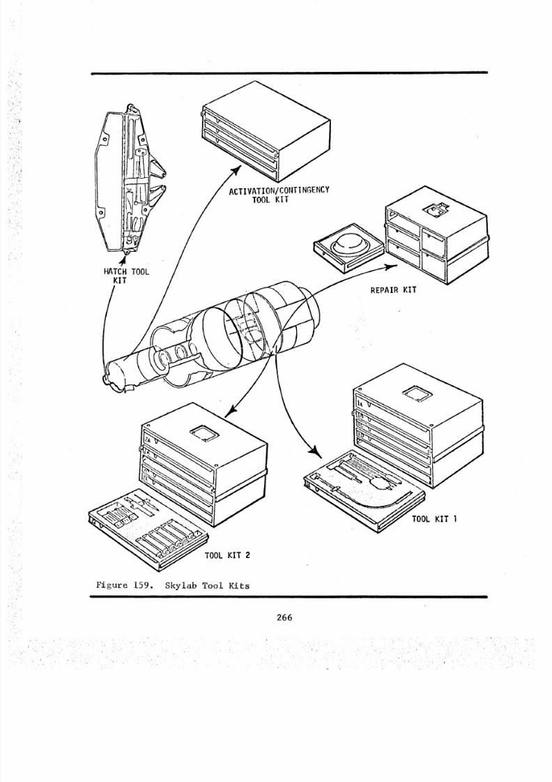
8/8/2019 MSFC Skylab Crew Systems Mission Evaluation
http://slidepdf.com/reader/full/msfc-skylab-crew-systems-mission-evaluation 290/397
\\
II?
_L KIT I
TOOL KIT 2
Figure 159. Skylab Tool Kits
266
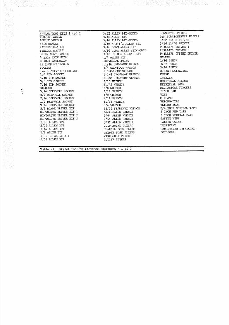
8/8/2019 MSFC Skylab Crew Systems Mission Evaluation
http://slidepdf.com/reader/full/msfc-skylab-crew-systems-mission-evaluation 291/397
_O
O%
SK_ TOOL KITS I and 2
TORQUE HANDLE
TORQUE _RENCH
SPIN HANDLERATCHET HANDLE
SPEEDER HANDLE
EXPERIMENT HANDLE
4 INCH EXTENSION
8 INCH EXTENSION
12 INCH EXTENSION
SOCKETS
1/4 8 POINT STD SOCKET1/4 STD SOCKET
5/16 STD SOCKET
3/8 STD SOCKET
7/16 STD SOCKET
SOCKETS
5/16 DEEPWELL SOCKET
3/8 DEEPWELL SOCKET
7/16 DEEPWELL SOCKET1/2 DEEPWELL SOCKET
9/16 DEEPWELL SOCKET
3/8 BLADE DRIVER BIT
HI-TORQUE DRIVER BIT 1
HI-TORQUE DRIVER BIT 2
HI-TORQUE DRIVER BIT 3
1/16 ALLEN _ B IT
3/32 ALLEN BIT
7/64 ALLEN BIT
1/8 ALLEN BIT
5/32 SQ ALLEN BIT5/32 ALLEN BIT
5/32 ALLEN BIT-MODED
3/16 ALLEN BIT
3/16 ALLEN BIT-MODED
3/16 X 3-1/2 ALLEN BIT
3/16 LONG ALLEN BIT
3/16 LONG ALLEN BIT-MODED
3/16 90 DEG ALLEN BIT
1/4 AI/_N BIT
UNIVERSAL JOINT
11/16 CROWFOOT WRENCH
3/4 CROWFOOT WRENCH
i CROWFOOT WRENCH
1-1/8 CROWFOOT WRENCH
1-3/8 CROWFOOT WRENCH
5/16 WRENCH
11 /32 WRENCH3/8 WRENCH
7/16 WRENCH
1/2 WRENCH
9116 WRENCH
11/16 WRENCH3/4 WRENCH
13 / 16 FLARENUT WRENCH
ADJUSTABLE WRENCH
3/64 ALLEN WRENCH
5/64 ALLEN WRENCH
3/32 ALLEN WRENCH
SLIP JOINT PLIERS
CHANNEL LOCK PLIERS
NEEDLE NOSE PLIERS
VISE GRIP PLIERS
CUTTER PLIERS
CONNECTOR PLIERS
PIN STRAIGHTENER PLIERS
3/32 BLADE DRIVER3/16 BLADE DRIVER
PHILLIPS DRIVER 1
PHILLIPS DRIVER 2
PHILLIPS OFFSET DRIVER
HAMMER
1/16 PUNCH
3/32 PUNCH
3/16 PUNCH
0-R ING EXTRACTO R
KNIFE
TWEEZER
RETRIEVAL MIRRORRETRIEVAL HOOK
MECHANICAL FINGERS
PINCH BAR
VISE
C CLAMP
VELCRO- PILEVELCRO-HOOK
3/4 INCH NEUTRAL TAPE
1 INCH RED TAPE2 INCH NEUTRAL TAPE
SAFETY WIPE
LACING TWINE
LUBRICANT
H20 SYSTEM LUBRICANT
SCISSORS
Table 23. Skylab Tool/Maintenance Equipment - 1 of 3
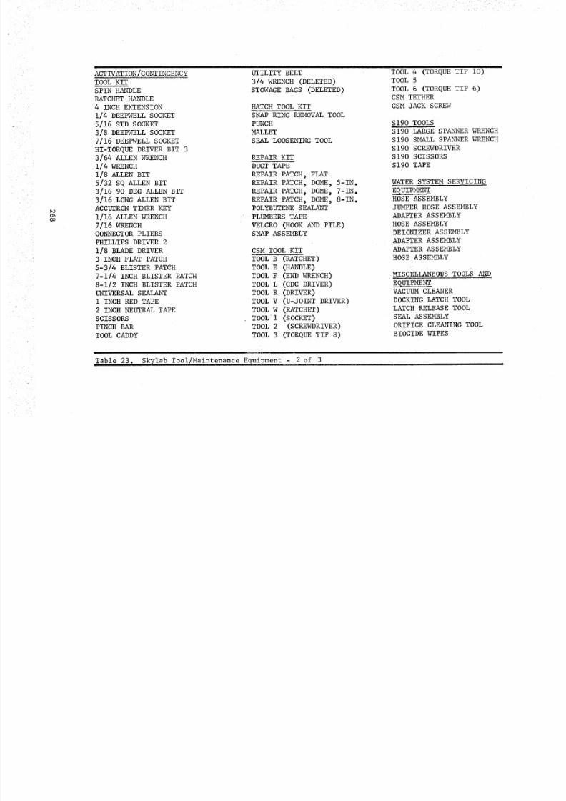
8/8/2019 MSFC Skylab Crew Systems Mission Evaluation
http://slidepdf.com/reader/full/msfc-skylab-crew-systems-mission-evaluation 292/397
r,o
co
ACTIVATION/CONTINGENCY
TOOL KIT
SPIN HANDLE
RATCHET HANDLE
4 INCH EXTENSION
1/4 DEEPWELL SOCKET
5/16 STD SOCKET
3/8 DEEPWELL SOCKET
7/16 DEEPWELL SOCKET
HI-TORQUE DRIVER BIT 3
3/64 ALLEN WRENCH
1/4 WRENCH
1/8 ALLEN BIT
5/32 SQ ALLEN BIT
3/16 90 DEG ALLEN BIT
3/16 LONG ALLEN BITACCUTRON TIMER KEY
1 / 16 ALLEN WRENCH
7/16 WRENCH
CONNECTOR PLIERS
PHILLIPS DRIVER 2
1/8 BLADE DRIVER
3 INCH FLAT PATCH
5-3/4 BLISTER PATCH
7-1/4 INCH BLISTER PATCH
8-1/2 INCH BLISTER PATCH
UNIVERSAL SEALANT
1 INCH RED TAPE
2 INCH NEUTRAL TAPE
SCISSORS
PINCH BAR
TOOL CADDY
l
UTILITY BELT
3/4 WRENCH (DELETED)
STOWAGE BAGS (DELETED)
HATCH TOOL KIT
SNAP RING REMOVAL TOOL
PUNCH
MALLET
SEAL LOOSENING TOOL
REPAIR KIT
DUCT TAPE
REPAIR PATCH, FLAT
REPAIR PATCH, DOME, 5-1N.
REPAIR PATCH, DOME, 7-1N.
REPAIR PATCH, DOME, 8-IN.POLYBUTENE SEALANT
PLUMBERS TAPEVELCRO (HOOK AND PILE)SNAP ASSEMBLY
CSM TOOL KIT
TOOL B (RATCHET)
TOOL E (HANDLE)
TOOL F (END WRENCH)
TOOL L (CDC DRIVER)
TOOL R (DRIVER)
TOOL V (U-JOINT DRIVER)
TOOL W (RATCHET)
TOOL I (SOCKET)TOOL 2 (SCREWDRIVER)
TOOL 3 (TORQUE TIP 8)
TOOL 4 (TORQUE TIP i0)
TOOL 5
TOOL 6 (TORQUE TIP 6)CSM TETHER
CSM JACK SCREW
S190 TOOLS
S190 LARGE SPANNER WRENCH
S190 SMALL SPANNER WRENCH
S190 SCREWDRIVER
S1 90 SCISSORS
S190 TAPE
WATER SYSTEM SERVICING
EQ PMENTHOSE ASSEMBLY
JUMPER HOSE ASSEMBLYADAPTER ASSEMBLY
HOSE ASSEMBLY
DEIONIZER ASSEMBLY
ADAPT ER A SSEMBLY
ADAPT ER A SSEMBLY
HOSE ASSEMBLY
MISCELLANEOUS TOOLS ANDEquIPMENTVACUUM CLEANER
DOCKING LATCH TOOL
LATCH RELEASE TOOL
SEA L ASSEMB LY
ORIFICE CLEANING TOOL
BIOCIDE WIPES
±
Table 23. Skylab Tool/Maintenance Equipment - 2 of 3
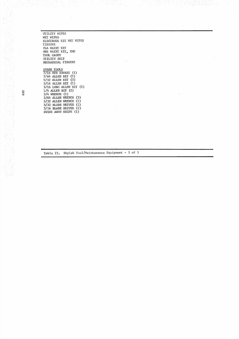
8/8/2019 MSFC Skylab Crew Systems Mission Evaluation
http://slidepdf.com/reader/full/msfc-skylab-crew-systems-mission-evaluation 293/397
_O
O_
_O
UTILITY WIPES
WET WIPES
ELECTRODE KIT WET WIPES
TISSUES
PGA MAINT KIT
OWS MAINT KIT_ EMUTOOL CADDY
UTILITY BELT
MECHANICAL FINGERS
SPARE TOOLS
7/16 STD SOCKET (I)
7/64 ALLEN BIT (I)
5/32 ALLEN BIT (3)
3/16 ALLEN BIT (I)
3/16 LONG ALLEN BIT (I)
1/4 ALLEN BIT (2)
3/4 WRENCH (I)
3/64 ALLEN WRENCH (3)
3/32 ALLEN WRENCH (I)
3/32 BLADE DRIVER (I)
3/16 BLADE DRIVER (I)
SWISS ARMY KNIFE (I)
Table 23. Skylab Tool/Maintenance Equipment - 3 of 3I
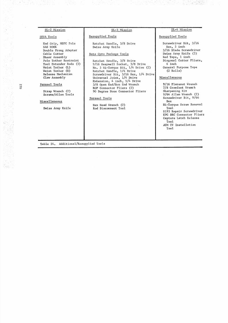
8/8/2019 MSFC Skylab Crew Systems Mission Evaluation
http://slidepdf.com/reader/full/msfc-skylab-crew-systems-mission-evaluation 294/397
o
SL-2 Mission
SEVA Tools
End Grip, MSFC PoleSAS HOOK
Double Prong AdapterCable Cutter
Shear AssemblyPole Tether Restraint
Tool Extender Rods (3)
Waist Tether (L)
Waist Tether (R)Rel eas e Mechani sm
Claw Assembly
Parasol Tools
Strap Wrench (2)
Screws/Allen Tools
Miscellaneous
Swiss Army Knife
SL-3 Mission
Resupplied Tools
Ratchet Handle, 3/8 Drive
Swiss Army Knife
Rate Gyro Package Tools
Ratchet Handle, 3/8 Drive
9/16 Deepwell Socket, 3/8 Drive
No. 3 Hi-Torque Bit, 1/4 Drive (2)
Ratchet Handle, 1/4 Drive
Screwdriver Bit, 3/16 Hex, 1/4 Drive
Universal Joint, 1/4 Drive
Extension, 4 inch, 1/4 Drive
3/8 Open End/Box End Wrench
RGP Connector Pliers (2)
90 Degree Nose Connector Pliers
Parasol Tools
Hex Head Wrench (2)
Rod Disconnect Tool
SL-4 Mission
Resupplied Tools
Screwdriver Bit, 3/16
Hex, 5 inch
3/16 Blade Screwdriver
Swiss Army Knife (3)
Red Tape, i inch
Diagonal Cutter Pliers,6 inch
General Purpose Tape
(2 Ro lls )
Miscellaneous
9/16 Flarenut Wrench
7/8 Crowfoot Wrench
Sharpening Kit9/64 Allen Wrench (2)
Screwdriver Bit, 9/64
Hex
Hi-Torque Screw RemovalTool
S193 Repair ScrewdriverEPC DRC Connector Pliers
Capture Latch ReleaseTool
ATMTV Installation
Tool
Table 24. Additional/Resupplied Tools
8/8/2019 MSFC Skylab Crew Systems Mission Evaluation
http://slidepdf.com/reader/full/msfc-skylab-crew-systems-mission-evaluation 295/397
2. _ - According to the crew_ comments,nearly all of thetools in the tool kits were used during the missions. Table 25 isa listing of these usages based on review of flight planning data,voice and dumptape transcripts, checklists, real time contingencyand maintenance procedures, and crew debriefings.
3. Losses and Failures - During the course of the three missions_
one ratchet handle failed_ the 4 inch diagonal cutters and one 5-inch
long, 3/16-hex screwdriver bit were broken and one pinch bar was lost.A retaining ring was either missing or was lost from the ratchet
directional control lever and the mechanism fell apart during SL-2
Activation. Procedures were developed to repair the ratchet but
were not performed. A replacement ratchet handle was launched onSL-3.
The diagonal cutters were broken during an attempt to remove the
spheres from the M553 sphere forming wheel. The 4-inch cutters were
inadequate for this purpose and jaws yielded when the task was
attempted. A larger, 6-inch, set of diagonal cutters were providedon SL-4. The SL-4 crew reported that the 6-inch cutters were dullafter only a few uses.
During the SL-2 crew debriefing, the crew stated that one of the
5-inch long, 3/16-hex screwdriver bits was defective. The bit shank
turned in the socket adapter. Since a spare bit was provided on-board,
resupply was determined not to be necessary. The same defective tool
was reported by the SL-3 crew during replacement of the Video Tape
Recorder. The SL-3 crew acquired the spare bit and completed the
task. Because of some confusion with the exact tool description a
spare modified type, 5-inch long, 3/16-hex screwdriver bit was launchedon SL-4. The 3/16-hex screwdriver bits were high usage tools on allthree Skylab missions.
The pinch bar which was used during the OWS Solar Wing deploymentactivity was left tethered to the wing. A replacement was determined
not to be necessary due to limited usage identified for the pinchbars and the fact that there were two initially stowed on-board.
During SL-4 the soft inserts in the jaws of the connector pliersbecame loose and had to be taped in place.
4. Post Mission Assessment - Sufficient tools were providedon-board to perform all planned activation, operational and maintenance
tasks. The on-board tools also proved to be adequate for support of
most of the contingency maintenance tasks. Some additional tools were
required to perform specific tasks, since complete sets of Allen
wrenches, sockets, and open end wrenches were not proved. The SL-3
crew also expressed a need for a hacksaw, drill, drill bits, largerscrewdrivers, and a sharpening stone. Special purpose tools were
required for support of the Standup EVA, Parasol deployment, OWS
Solar Wing deployment, Rate Gyro Package installation, and installation
271
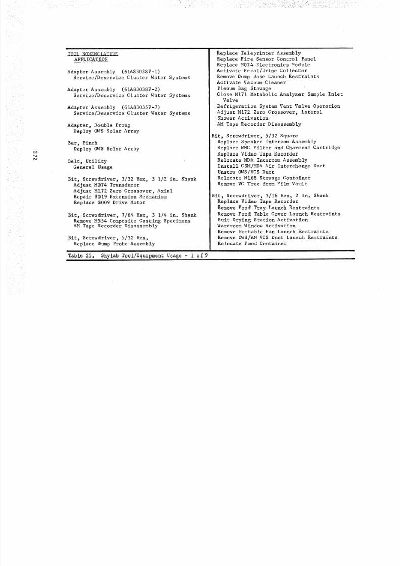
8/8/2019 MSFC Skylab Crew Systems Mission Evaluation
http://slidepdf.com/reader/full/msfc-skylab-crew-systems-mission-evaluation 296/397
_O
_O
II
TOOL NOMENC L_TUREAPPLICATION
Adapter Assembly (61A830387-I)Service/Deservice Cluster Water Systems
Adapter Assembly (61A830387-2)
Service/Deservice Cluster Water Systems
Adapter Assembly (61A830357-7)Service/Deservice Cluster Water Systems
Adapter, Double Prong
Deploy OWS Solar Array
Bar, Pinch
Deploy OWS Solar Array
Belt, Utility
General Usage
Bit, Screwdriver, 3/32 Hex, 3 1/2 in. Shank
Adjust M074 Transducer
Adjust M172 Zero Crossover, Axial
Repair S019 Extension MechanismReplace S009 Drive Motor
Bit, Screwdriver, 7/64 Hex, 3 1/4 in. Shank
Remove M554 Composite Casting SpecimensAM Tape Recorder Disassembly
Bit, Screwdriver, 5/32 Hex,
Replace Dump Probe Assembly
I
Table 25. Skylab Tool/Equipment Usage - i of 9
i
Replace Teleprinter Assembly
Replace Fire Sensor Control Panel
Replace M074 Electronics ModuleActivate Fecal/Urine Collector
Remove Dump Hose Launch RestraintsActivate Vacuum Cleaner
Plenum Bag Stowage
Close MI71 Metabolic Analyzer Sample InletValve
Refrigeration System Vent Valve Operation
Adjust M172 Zero Crossover, LateralShower Activat ion
AM Tape Recorder Disassembly
Bit, Screwdriver, 5/32 Square
Replace Speaker Intercom Assembly
Replace WMC Filter and Charcoal Cartridge
Replace Video Tape Recorder
Relocate MDA Intercom Assembly
Install CSM/MDA Air Interchange Duct
Unstow OWS/VCS Duct
Relocate M168 Stowage ContainerRemove VC Tree from Film Vault
Bit, Screwdriver, 3/16 Hex, 2 in. Shank
Replace Video Tape Recorder
Remove Food Tray Launch RestraintsRemove Food Table Cover Launch Restraints
Suit Drying Station ActivationWardroom Window Activation
Remove Portable Fan Launch Restraints
Remove OWS/AM VCS Duct Launch Restraints
Relocate Food Container
|
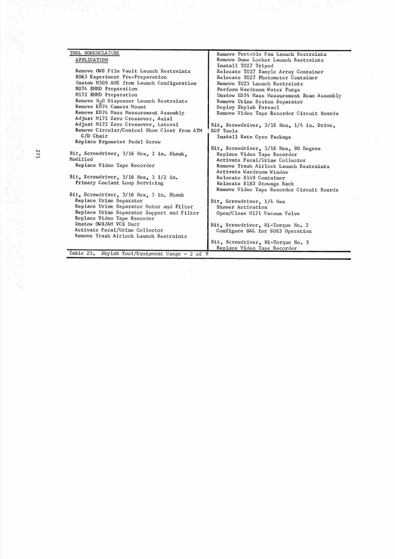
8/8/2019 MSFC Skylab Crew Systems Mission Evaluation
http://slidepdf.com/reader/full/msfc-skylab-crew-systems-mission-evaluation 297/397
_OLO
TOOL NOMENCLATURE
APPLICATION
Remove OWS Film Vault Launch Restraints
S063 Experiment Pre -Prepara tion
Unstow M509 AME from Launch ConfigurationM07 4 S M_4D Preparati on
M172 BMMD PreparationRemove H20 Dispenser Launch RestraintsRemove ED74 Camera Mount
Remove ED74 Mass Measurement Assembly
Adjust M172 Zero Crossover, Axial
Adjust M172 Zero Crossover, LateralRemove Circular/Conical Shoe Cleat from ATM
C/D Chair
Replace Ergometer Pedal Screw
Bit, Screwdriver, 3/16 Hex, 2 in. Shank,Modified
Replace Video Tape Recorder
Bit, Screwdriver, 3/16 Hex, 3 1/2 in.
Primary Coolant Loop Servicing
Bit, Screwdriver, 3/16 Hex, 5 in. Shank
Replace Urine Separator
Replace Urine Separator Motor and Filter
Replace Urine Separator Support and Filter
Replace Video Tape RecorderUnstow OWS/AM VCS Duct
Activate Fecal/Urine Collector
Remove Trash Airlock Launch Restraints
Table 25.|
Skylab Tool/Equipment Usage - 2 of 9
Remove Portable Fan Launch Restraints
Remove Dome Locker Launch Restraints
Install T027 Tripod
Relocate T027 Sample Array ContainerRelocate T027 Photometer Container
Remove T025 Launch Restraints
Perform Wardroom Water Purge
Unstow ED74 Mass Measurement Beam AssemblyRemove Urine System Separator
Deploy Skylab Parasol
Remove Video Tape Recorder Circuit Boards
Bit, Screwdriver, 3/16 Hex, 1/4 in. Drive,RGP Tools
Install Rate Gyro Package
Bit, Screwdriver, 3/16 Hex, 90 Degree
Replace Video Tape RecorderActivate Fecal/Urine Collector
Remove Trash Airlock Launch Restraints
Activate Wardroom Window
Relocate S149 Container
Relocate S183 Stowage Rack
Remove Video Tape Recorder Circuit Boards
Bit, Screwdriver, 1/4 HexShower Activat ion
Open/Close MI71 Vacuum Valve
Bit_ Screwdriver, Hi-Torque No. 2
Configure SAL for S063 Operation
Bit, Screwdriver, Hi-Torque No. 3
Replace Video Tape Recorder
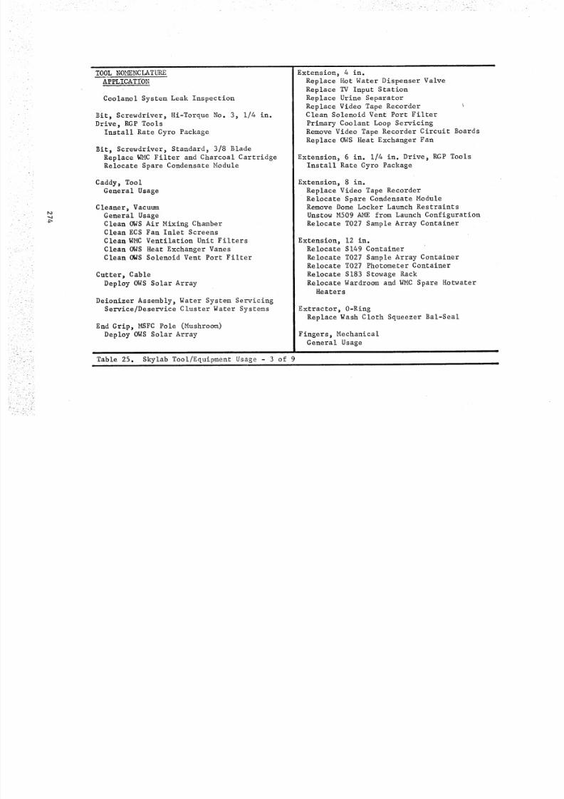
8/8/2019 MSFC Skylab Crew Systems Mission Evaluation
http://slidepdf.com/reader/full/msfc-skylab-crew-systems-mission-evaluation 298/397
_O
_4
TOOL NOMENCLATURE
APPLICAT£ON
Coolanol System Leak Inspection
Bit, Screwdriver, Hi-Torque No. 3, 1/4 in.
Drive, RGP Tools
Install Rate Gyro Package
Bit, Screwdriver, Standard, 3/8 Blade
Replace WMC Filter and Charcoal CartridgeRelocate Spare Condensate Module
Caddy, ToolGeneral Usage
Cleaner, Vacuum
General Usage
Clean OWS Air Mixing ChamberClean ECS Fan Inlet Screens
Clean WMC Ventilation Unit Filters
Clean OWS Heat Exchanger VanesClean OWS Solenoid Vent Port Filter
Cutter, Cable
Deploy OWS Solar Array
Deionizer Assembly, Water System Servicing
Service/Deservice Cluster Water Systems
End Grip, MSFC Pole (Mushroom)
Deploy OWS Solar Array
Table 25. Skylab Tool/Equipment Usage - 3 of 9
Extension, 4 in.
Replace Hot Water Dispenser Valve
Replace TV Input Station
Replace Urine Separator
Replace Video Tape RecorderClean Solenoid Vent Port Filter
Primary Coolant Loop Servicing
Remove Video Tape Recorder Circuit Boards
Replace OWS Heat Exchanger Fan
Extension, 6 in. 1/4 in. Drive, RGP Tools
Install Rate Gyro Package
Extension, 8 in.
Replace Video Tape Recorder
Relocate Spare Condensate ModuleRemove Dome Locker Launch Restraints
Unstow M509 AME from Launch Configuration
Relocate T027 Sample Array Container
Extension, 12 in.Relocate S149 Container
Relocate T027 Sample Array ContainerRelocate T027 Photometer Container
Relocate S183 Stowage Rack
Relocate Wardroom and WMC Spare HotwaterHeaters
Extractor, 0-Ring
Replace Wash Cloth Squeezer Bal-Seal
Finge rs, Mechan ica l
General Usage
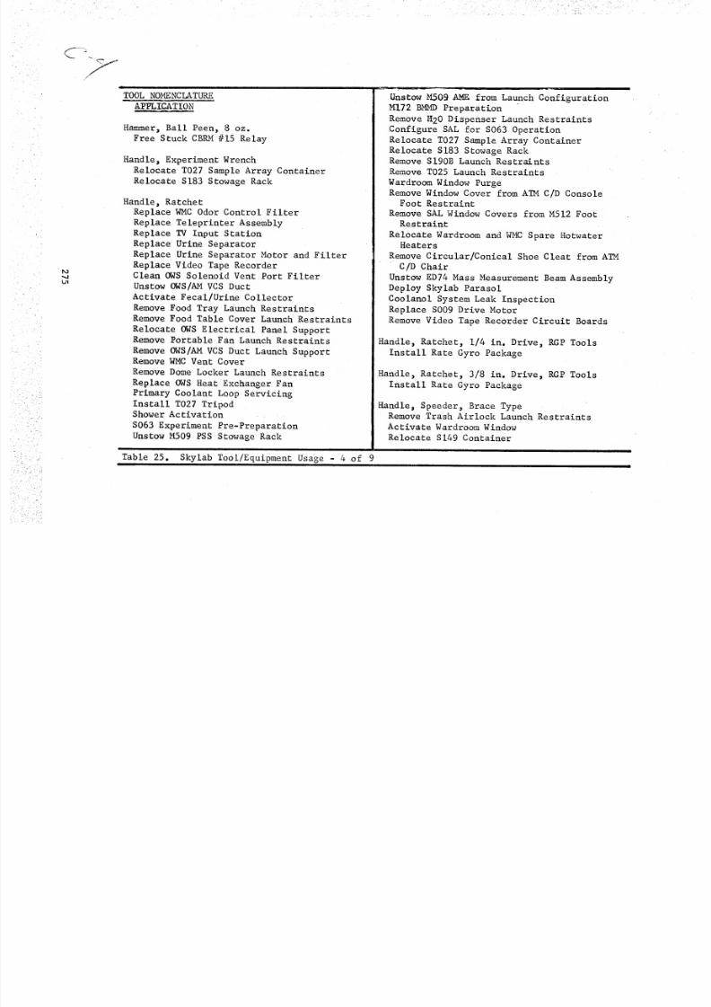
8/8/2019 MSFC Skylab Crew Systems Mission Evaluation
http://slidepdf.com/reader/full/msfc-skylab-crew-systems-mission-evaluation 299/397
/
L_
TOOL NOMENCLATURE
APPLICATION
Hammer, Ball Peen, 8 oz.
Free Stuck CBRM #15 Relay
Handle, Experiment Wrench
Relocate T027 Sample Array ContainerRelocate S183 Stowage Rack
Handle, Ratchet
Replace WMC Odor Control Filter
Replace Teleprinter Assembly
Replace TV Input Station
Replace Urine Separator
Replace Urine Separator Motor and FilterReplace Video Tape RecorderClean OWS Solenoid Vent Port Filter
Unstow OWS/AM VCS Duct
Activate Fecal/Urine Collector
Remove Food Tray Launch Restraints
Remove Food Table Cover Launch Restraints
Relocate OWS Electrical Panel SupportRemove Portable Fan Launch Restraints
Remove OWS/AMVCS Duct Launch SupportRemove WMC Vent Cover
Remove Dome Locker Launch Restraints
Replace OWS Heat Exchanger Fan
Primary Coolant Loop Servicing
Install T027 TripodShower Activat ion
S063 E xperi men t P re -Prepa ra tion
Unstow M509 PSS Stowage Rack
Table 25. Skylab Tool/Equipment Usage - 4 of 9
UnstowM.5OgAM_ from Launch Configuration
M172 B_MD Preparation
Remove _20 Dispenser Launch Restraints
Configure SAL for S063 Operation
Relocate T027 Sample Array Container
Relocate S183 Stowage RackRemove SI90B Launch Restraints
Remove T025 Launch RestraintsWardroom Window PurgeRemove Window Cover from ATMC/D Console
Foo t Re str ain t
Remove SAL Window Covers from M512 FootRestraint
Relocate Wardroom and WMC SpareHotwaterHeaters
Remove Circular/Conical Shoe Cleat from ATM
C/D Chair
Unstow ED74 Mass Measurement Beam Assembly
Deploy Skylab Parasol
Coolanol System Leak InspectionReplace S009 Drive Motor
Remove Video Tape Recorder Circuit Boards
Handle, Ratchet, 1/4 in. Drive, RGP ToolsInstall Rate Gyro Package
Handle, Ratchet, 3/8 in. Drive, RGP Tools
Install Rate Gyro Package
Handle, Speeder, Brace TypeRemove Trash Airlock Launch Restraints
Activate Wardroom Window
Relocate S149 Container

8/8/2019 MSFC Skylab Crew Systems Mission Evaluation
http://slidepdf.com/reader/full/msfc-skylab-crew-systems-mission-evaluation 300/397
L
_O
TOOL NOMENCLATURE
APPLICATION
Remove Film Vault Launch Restraints
Relocate T027 Photometer Container
Remove ED74 Camera Mount
Remove ED74 Mass Measurement Assembly
Handle, Spin Type
Replace Dump Probe Assembly
Replace WMC Filter and Charcoal Cartridge
Replace Fire Sensor Control Panel
Replace M074 Electronics Module
Relocate MDA Speaker Intercom AssemblyInstall CSM/MDA Air Interchange DuctActivate Fecal/Urine Collector
SAL Window Initial Installation
Remove Dump Hose Launch RestraintsActivate Wardroom Window
Activate Vacuum Cleaner
Relocate M168 Stowage Container
Relocate Spare Condensate ModuleShower Activat ion
M074 SMMD Preparation
Install Urine SeparatorRelocate T027 Sample Array Container
Relocate S183 Stowage Rack
Plenum Bag Stowage
Remove M554 Composite Casting Specimens
Refrigeration System Vent Valve Operation
Adjust M074 Transducer
Adjust M172 Zero Crossover, Axial
Table 25. Skylab Tool/Equipment Usage - 5 of 9
Adjust M172 Zero Crossover, LateralRemove VC Tree from Film Vault
Remove Urine Separator
Repair S019 Extension Mechanism
AM Tape Recorder Disassembly
Handle, Torque, 5-150 in.-ibs.
Replace Urine Separator Support and FilterReplace Video Tape RecorderRelocate Food Container
Close MI71 Metabolic Analyzer Sample Inlet
Valve
Open/Close MI71 Metabolic Analyzer VacuumValve
Wardroom Window Moisture Removal
Replace Ergometer Pedal Screw
Primary Coolant Loop Servicing
Hook, SAS
Deploy OWS Solar Array
Hose Assembly, Water Servicing DeionizerService/Deservice Cluster Water Systems
Hose Assembly, JumperService/Deservice Cluster Water Systems
Hose Assembly, Water Separator Plates
Service/Deservice Cluster Water Systems
Hose Assembly, Water System Servicing
(61A830355-13)
Service/Deservice Cluster Water Systems
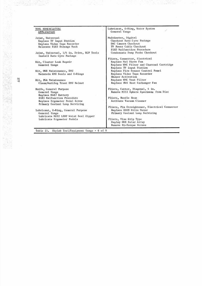
8/8/2019 MSFC Skylab Crew Systems Mission Evaluation
http://slidepdf.com/reader/full/msfc-skylab-crew-systems-mission-evaluation 301/397
,.,,.,j'.,.,,,t
TOOL NOMENCLATURE
AIrPLICATION
Joint, Uni ver sa l
Replace TV Input Station
Replace Video Tape RecorderRelocate S183 Stowage Rack
Joint, Universal, 1/4 in. Drive, RGP Tools
Install Rate Gyro Package
Kit, Cluster Leak Repair
General Usage
Kit, OWS Maintenance, EMU
Maintain EMU Seals and 0-Rings
Kit, PGA Maintenance
Clean/Antifog Treat EMU Helmet
Knife, General Purpose
General Usage
Replace M487 Battery
S183 Malfunction ProcedureReplace Ergometer Pedal Screw
Primary Coolant Loop Servicing
Lubricant, O-Ring, General Purpose
General UsageLubricate M092 LBNP Waist Seal Zipper
Lubricate Ergometer Pedals
Table 25. Skylab Tool/Equipment usage - 6 of 9
Lubricant, 0-Ring, Water System
General Usage
Multimeter, DigitalCheckout Rate G yro PackageDAC Camera Checkout
TV Power Cable Checkout
S183 Malfunction Procedure
Condensate Dump Probe Checkout
Pliers, Connector, Electrical
Replace Mol Sieve Fan
Replace WMC Filter and Charcoal Cartridge
Replace TV input Station
Replace Fire Sensor Control Panel
Replace Video Tape RecorderShower Activat ion
Replace WMC Vent Filter
Replace OWS Heat Exchanger Fan
Pliers, Cutter, Diagonal, 4 in.
Remove M553 Sphere Specimens from Disc
Pliers, Needle NoseActivate Vacuum Cleaner
Pliers, Pin Straightener, Electrical Connector
Replace S009 Drive Motor
Primary Coolant Loop Servicing
Pliers, Vise Grip Type
Deploy OWS Solar ArrayRemove Hi-Torque Screws
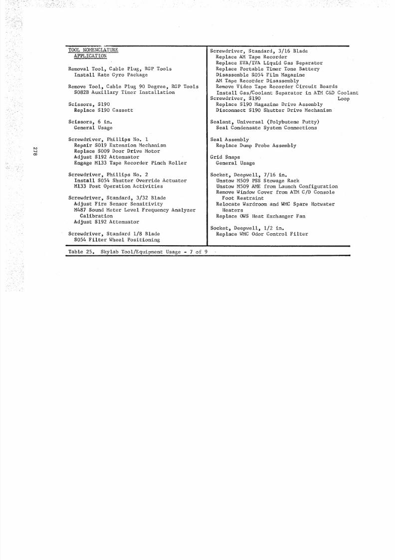
8/8/2019 MSFC Skylab Crew Systems Mission Evaluation
http://slidepdf.com/reader/full/msfc-skylab-crew-systems-mission-evaluation 302/397
• •• •• • r•̧ _ _ __ ! i_ _ _ _i /
_o
Oo
TOOL NOMENCLATURE
APPLICATION
Removal Tool, Cable Plug, RGP Tools
Install Rate Gyro Package
Remove Tool, Cable Plug 90 Degree, RGP ToolsS082B Auxillary Timer Installation
Scissors, S190
Replace S190 Cassett
Scissors, 6 in.
General Usage
Screwdriver, Phillips No. i
Repair S019 Extension Mechanism
Replace S009 Door Drive Motor
Adjust S192 Attenuator
Engage M133 Tape Recorder Pinch Roller
Screwdriver, Phillips No. 2Install S054 Shutter Override Actuator
M133 Post Operation Activities
Screwdriver, Standard, 3/32 Blade
Adjust Fire Sensor Sensitivity
M487 Sound Meter Level Frequency AnalyzerCalibration
Adjust S192 Attenuator
Screwdriver, Standard 1/8 Blade
S054 Filter Wheel Positioning
Table 25. Skylab Tool/Equipment Usage - 7 of 9
Screwdriver, Standard, 3/16 Blade
Replace AM Tape Recorder
Replace EVA/IVA Liquid Gas Separator
Replace Portable Timer Tone Battery
Disassemble &054 Film Magazine
AM Tape Recorder Disassembly
Remove Video Tape Recorder Circuit Boards
Install Gas/Coolant Separator in ATM C&D Coolant
Screwdriver, S190 LoopReplace S190 Magazine Drive AssemblyDisconnect S190 Shutter Drive Mechanism
Sealant, Universal (Polybutene Putty)
Seal Condensate System Connections
Seal Assembly
Replace Dump Probe Assembly
Grid Snaps
General Usage
Socket, Deepwell, 7/16 in.
Unstow M509 PSS Stowage RackUnstow M509 AME from Launch Configuration
Remove Window Cover from ATMC/D ConsoleFoo t Re str ain t
Relocate Wardroom and WMC Spare HotwaterHeaters
Replace OWS Heat Exchanger Fan
Socket, Deepwell, 1/2 in.
Replace WMC Odor Control Filter
k_
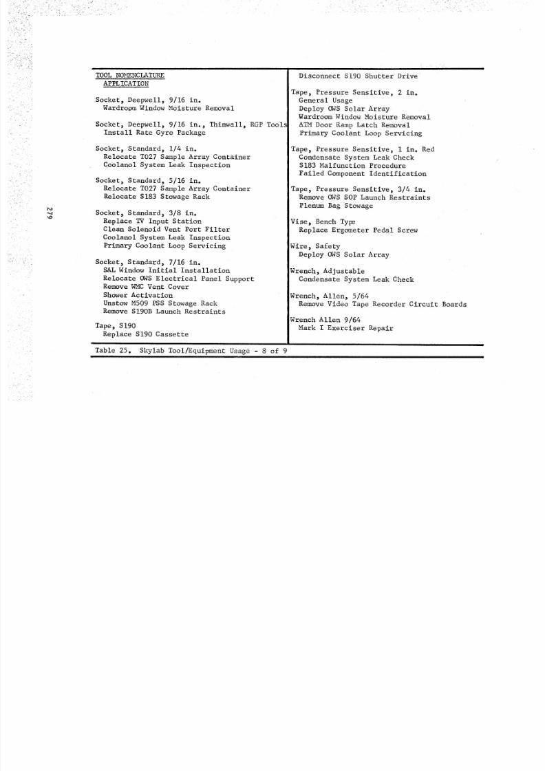
8/8/2019 MSFC Skylab Crew Systems Mission Evaluation
http://slidepdf.com/reader/full/msfc-skylab-crew-systems-mission-evaluation 303/397
• i ¸ i ri•iiill i!iiii•• i _ _ i? i • _ • L •
_o
TOOL NOMENCLATURE
APPL ICATION
Socket, Deepwell, 9/16 in.Wardroom Window Moisture Removal
Socket, Deepwell, 9/16 in., Thinwall, RGP Tools
Install Rate Gyro Package
Socket, Standard, 1/4 in.
Relocate T027 Sample Array Container
Coolanol System Leak Inspection
Socket, Standard, 5/16 in.
Relocate T027 Sample Array Container
Relocate S183 Stowage Rack
Socket, Standard, 3/8 in.
Replace TV Input StationClean Solenoid Vent Port Filter
Coolanol System Leak Inspection
Primary Coolant Loop Servicing
Socket, Standard, 7/16 in.SAL Window Initial Installation
Relocate OWS Electrical Panel SupportRemove WMC Vent Cover
Shower Activat ion
Unstow M509 PSS Stowage RackRemove SI90B Launch Restraints
Tape, $190
Replace S190 Cassetteit
Table 25. Skylab Tool/Equipment Usage - 8 of 9
Disconnect S190 Shutter Drive
Tape, Pressure Sensitive, 2 in.
General Usage
Deploy OWS Solar ArrayWardroomWindow Moisture Removal
ATMDoor Ramp Latch Removal
Primary Coolant Loop Servicing
Tape, Pressure Sensitive, I in. Red
Condensate System Leak CheckS183 Malfunction Procedure
Failed Component Identification
Tape, Pressure Sensitive, 3/4 in.Remove OWS SOP Launch Restraints
Plenum Bag Stowage
Vise, Bench Type
Replace Ergometer Pedal Screw
Wire, Safety
Deploy OWS Solar Array
Wrenc h, A djustabl e
Condensate System Leak Check
Wrench, Allen, 5/64
Remove Video Tape Recorder Circuit Boards
Wrench Allen 9/64
Mark I Exerciser Repair
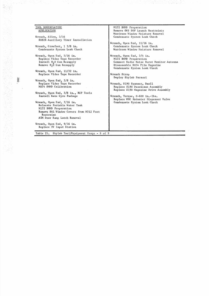
8/8/2019 MSFC Skylab Crew Systems Mission Evaluation
http://slidepdf.com/reader/full/msfc-skylab-crew-systems-mission-evaluation 304/397
8/8/2019 MSFC Skylab Crew Systems Mission Evaluation
http://slidepdf.com/reader/full/msfc-skylab-crew-systems-mission-evaluation 305/397
8/8/2019 MSFC Skylab Crew Systems Mission Evaluation
http://slidepdf.com/reader/full/msfc-skylab-crew-systems-mission-evaluation 306/397
A tool summaryor listing was not available on-board for crew visibil-ity of the entire tool inventory. As a consequence the crews wereunaware of the availability of certain tools unless they were speci-fied in a procedure and their location spelled out. This included
the tools initially provided as spares and those stowed throughoutthe cluster other than in the main tool kit in the OWS. The SL-4crew stated that they would like to have had the tools displayed onthe OWSwall the sameas a work shop would be layed out in order toprovide visibility of the tool inventory.
None of the tools in the initial tool inventory were designedfor EVAuse. As a consequence, tool handle sizes had to be enlargedby wrapping them with tape. Tape was also used to attach the necessarytethers, since the tools were not equipped with tethers or tetherattach points. The tools proved to be adequate for EVAafter thehandles were taped and the tethers attached. An adaptable EVAhandlefor standard tools and tether attach points would be desirable forany future tools required for EVAinflight Maintenance use.
The Velcro patches on the tools were of very little value. Insomecases the patches cameloose and they did not hold tight enoughto retain the tools on the tool caddy during translation. The mainusage was for retaining tools in the area of the SALwhere patches ofvelcro pile had been installed.
282
8/8/2019 MSFC Skylab Crew Systems Mission Evaluation
http://slidepdf.com/reader/full/msfc-skylab-crew-systems-mission-evaluation 307/397
E. IFM Summary and Conclusions
Skylab experience demonstrated that preplanned maintenance
capability resulted in relatively problem free, easily executed main-
tenance tasks, when coordinated with design. However, unanticipatedmaintenance activity created excessive resupply requirements for
special tools, spares and equipment, as well as consuming a great
deal of crew time and effort. Installation of the Rate Gyro Six
Pack, leak check of the coolant and condensate systems and attempted
removal of the ATM Control and Display Console kickplate are examples
of maintenance tasks unanticipated but accomplished on Skylab.
Excessive numbers of fasteners had to be removed, some types offasteners were unacceptable for maintenance purposes, not all tools
were available on-board and accessibility was poor. Special tools,jumper cables and installation hardware had to be developed on a realtime basis and provided on revisit missions.
Initial design concepts need to include inflight maintenance
provisions which must be developed concurrently with hardware design.
This philosophy permits incorporation of the necessary design featuresto facilitate failure detection, isolation, corrective action and
verification of repair. Stowage provisions for tools, spares, main-
tenance, equipment and space for maintenance work areas, must be
incorporated in the initial design. This is necessary to optimize
spacecraft maintenance support with available weight and volume; to
permit orderly arrangement of tools and equipment; and, facilitateperformance of bench repair.
Experience gained during Skylab has proven that extra-vehicular
maintenance is not only feasible, but is also a necessary capabilityfor success of space missions. The Skylab crewmen demonstrated that
tools could be effectively manipulated, equipment erected, electrical
connectors mated and demated and components removed and installed,when the necessary procedures, tools and equipment items were made
available. All of these capabilities were required in order to deploythe solar shade, connect the rate gyro package, deploy the OWS solar
wing and remove the AIM door ramp latches. Skylab experience also
demonstrated that EVA time could be extended beyond that anticipated,in order to accomplish necessary tasks. Most of the extra-vehicular
maintenance on Skylab was unanticipated and was accomplished based on
real time planning, without the assistance of built in translation
aids, restraints or tools intended for EVA applications.
Design criteria for maintainable spacecraft must include provisionsfor extra-vehicular inflight maintenance. This criteria must insure
that translation and restraint capability is provided for all potential
work areas; i.e., predetermined attaching points for handrails, restraintsand tethers.
Accessibility to equipment, attaching hardware, electrical connec-
tions and plumbing is imperative, even in areas where maintenance is
not anticipated or is highly unlikely. All failures and contingenciescannot be anticipated, but with adequate design criteria, correctivemaintenance action can be taken.
283
8/8/2019 MSFC Skylab Crew Systems Mission Evaluation
http://slidepdf.com/reader/full/msfc-skylab-crew-systems-mission-evaluation 308/397
Skylab crews expressed a preference for Calfax type quick releasefasteners and magnetic door latches as opposed to dial latches, pippins and Expando-Grip pins. Internal wrenching (Allen head) screwsand hex head bolts were the preferred types of attaching hardware.Hi-Torque and slotted type screws were unacceptable for inflightmaintenance purposes.
The experience gained on Skylab indicates that the astronautsare capable of performing complicated maintenance tasks during EVAand bench repair of major componentson IVA. Handling, alignment andmanipulation of large heavy items presented no problems in zerogravity. Small items such as bolts, screws, washers, nuts, etc., didpresent someproblems because they tend to float away and becomelost.However, these items usually found their way to one of the ECSinletscreens. Methods and techniques must be developed on future spaceprograms to enable the astronauts to handle and control these smallitems in an effective manner.
Selection of spares to support inflight maintenance capability
should include consideration of non-critical and redundant hardware.Skylab experience demonstrated the desirability of replacing orrepairing all failed equipment. With the exception of the contingencymaintenance performed, nearly all of the items replaced during themissions were identified as non-critical or redundant hardware. Thetape recorders, speaker intercom assemblies, water dispenser, massmeasuring device electronics, cameras and fans are just a few examples.Without these spares and manyothers of the sametype, the Skylabmission would still have been successful, but the degree of successwould have been reduced.
Spares selection for IFM should include repair parts for certainitems whose design permits inflight bench repair as well as replace-able assemblies. Skylab has proven that the crew, when provided theproper tools, procedures and parts, is capable of performing benchrepair of failed assemblies.
Tools selected for Skylab were primarily those required forspecific tasks that were approved for inflight accomplishment. Afew contingency type tools were included such as a pry bar, a hammerand the Swiss Army knife, which proved to be valuable assets. Allenwrenches of certain sizes were provided for specific application, allsizes were not provided. The sameapplied to open end wrenches,sockets, etc. The crews have expressed a desire for complete sets ofthese tools. It has also been indicated that regular off-the-selftype tools are adequate and no special finish is required for use inspace. A tool caddy for carrying tools from place to place should be
developed with the purpose in mind of facilitating the location of theneeded tool after arriving at the work station. Crew commentsindic-ated a "see through" material would be desirable. The caddy shouldalso provide a capability to hold small parts such as washers, screws,bolts, nuts, etc., since containing and locating these items was aproblem in zero gravity.
284
8/8/2019 MSFC Skylab Crew Systems Mission Evaluation
http://slidepdf.com/reader/full/msfc-skylab-crew-systems-mission-evaluation 309/397
The crew of SL-3 indicated that a portable leak detector shouldbe considered for future missions. This need becameevident whencoolant leaks and vacuumleaks were suspected and verified, but notisolated to a specific location. A desire of all crews was adedicated work bench or table with a capability for holding thingsthat tend to float away. This, with the availability of repair parts,would enhance the repair of failed assemblies. Future spacecraftdesign should include a maintenance package, incorporating benchrepair capability and containing a complete selection of generalpurpose tools and the necessary special tools and equipment to main-tain the spacecraft and payload systems. For future missions, toolsshould be equipped with tether attach points to restrain them duringEVAmaintenance activities.
The astronauts have indicated that the tasks and procedures wereso well planned and documentedthat manyof the maintenance tasks couldhave been performed efficiently with little or no maintenance training.In the future, the engineers and technicians must continue to workout the procedural details, verify the tasks on trainers and flighthardware, and provide accurate and concise procedures in order toreduce and/or eliminate maintenance training for the astronauts.
Training for inflight maintenance should be limited to complexrepair tasks which involve unusual equipment disassembly techniques,or tasks which could present a hazard to the crew, or result indamageto spacecraft equipment.
285
8/8/2019 MSFC Skylab Crew Systems Mission Evaluation
http://slidepdf.com/reader/full/msfc-skylab-crew-systems-mission-evaluation 310/397
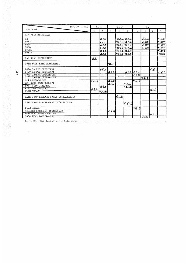
8/8/2019 MSFC Skylab Crew Systems Mission Evaluation
http://slidepdf.com/reader/full/msfc-skylab-crew-systems-mission-evaluation 311/397
t,O
oo
ATM FILM RETRIEVAL
HaS052
S054S056
S082A
S082B
SAS BEAM DEPLOYMENT
TWIN POLE SAIL DEPLOYMENT
D024 SAMPLE RETRIEVAL$230 SAMPLE RETRIEVAL
T025 CAMERA OPERATIONS
S201 CAMERA OPERATIONS
S149 DEPLOYMENTATM DOOR RAMP REMOVAL
S052 DISC CLEANINGATM DOOR OPENING
CBRMREPAIR
RATE GYRO PACKAGE CABLE INSTALLATION
SAIL SAMPLE INSTALLATION/RETRIEVAL
S193 REPAIR
VEHICLE EXTERIOR INSPECTION
MATERIAL SAMPLE RETURN
S054 LENS POSITIONING
Table 26. EVA Task-M_ssion Reference
VI.C
SL-2
2
VI,B_Vl.8,:_
VbB._VI.B._VI.B,3VI.B.3
_/I.E,,i
vi.¢,_o
VI.D
VI,E.Ft-
SL-3 SL-4
2 3 i 2 3
VI.B,?.. VI.B2_ IVI,B.2 V'I,B.'ZVI,_.?-VI.B..?- l_I.B2-! Vt,B.ZVI,B,2 VI,B,?- !VI,B,?-..l 'V'I,B._VI.B,2 VI,B,2. IVi.g,2.1 VI.B2_I.B,B _i,$.3 VI,t_,3VI, B.B FI,B.3 VI,B,B
v"l,_;.qv'i._.,_
VI,I_,II
Vi,_,12
VI.E.B
Vl._.4
VI,E,S
V'l._.9
_VI.E,l?__
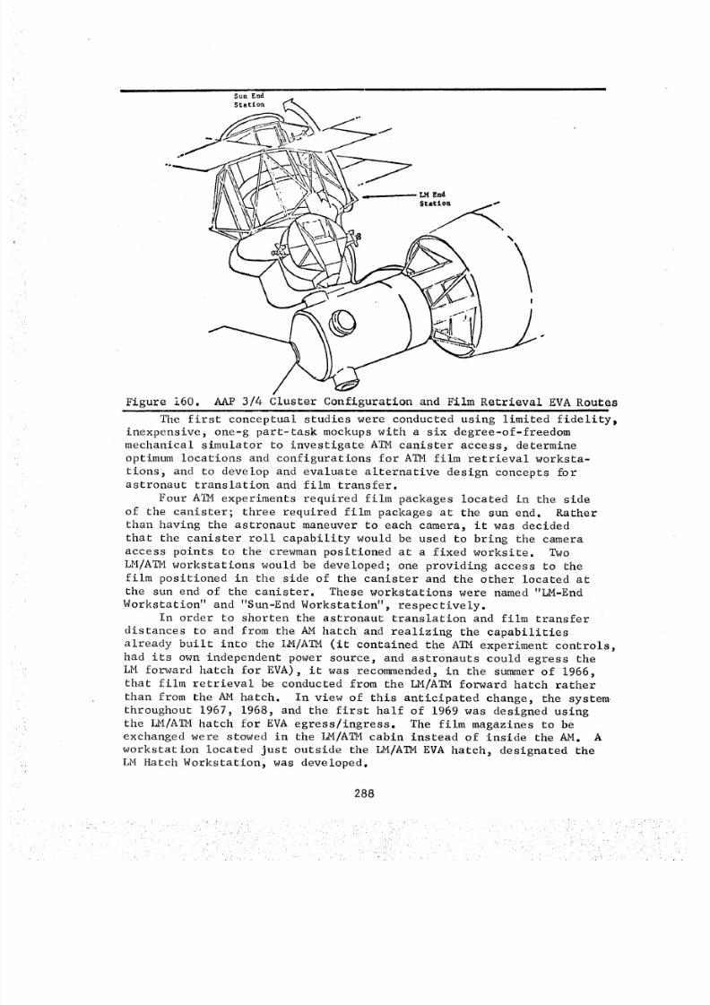
8/8/2019 MSFC Skylab Crew Systems Mission Evaluation
http://slidepdf.com/reader/full/msfc-skylab-crew-systems-mission-evaluation 312/397
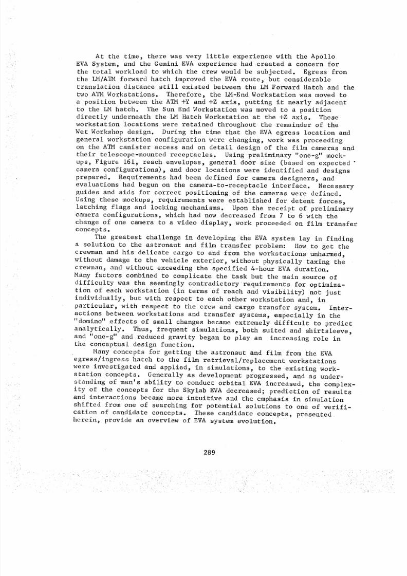
8/8/2019 MSFC Skylab Crew Systems Mission Evaluation
http://slidepdf.com/reader/full/msfc-skylab-crew-systems-mission-evaluation 313/397
At the time, there was very little experience with the ApolloEVASystem, and the Gemini EVAexperience had created a concern forthe total workload to which the crew would be subjected. Egress fromthe LM/ATMorward hatch improved the EVAroute, but considerabletranslation distance still existed between the LMForward Hatch and the
two ATMWorkstations. Therefore, the LM-EndWorkstation was movedtoa position between the ATM+Y and +Z axis, putting it nearly adjacentto the LMhatch. The SunEndWorkstation was movedto a positiondirectly underneath the LM Hatch Workstation at the +Z axis. Theseworkstation locations were retained throughout the remainder of theWet Workshopdesign. During the time that the EVAegress location andgeneral workstation configuration were changing, work was proceedingon the ATMcanister access and on detail design of the film camerasandtheir telescope-mounted receptacles. Using preliminary "one-g" mock-ups, Figure 161, reach envelopes, general door size (based on expected "camera configurations), and door locations were identified and designsprepared. Requirements had been defined for camera designers, andevaluations had begun on the camera-to-receptacle interface. Necessaryguides and aids for correct positioning of the cameraswere defined.Using these mockups, requirements were established for detent forces,latching flags and locking mechanisms. Uponthe receipt of preliminarycamera configurations, which had now decreased from 7 to 6 with thechange of one camera to a video display, work proceeded on film transferconcepts.
The greatest challenge in developing the EVAsystem lay in findinga solution to the astronaut and film transfer problem: Howto get thecrewmanand his delicate cargo to and from the workstations unharmed,without damageto the vehicle exterior, without physically taxing thecrewman, and without exceeding the specified 4-hour EVAduration.Many factors combined to complicate the task but the main source of
difficulty was the seemingly contradictory requirements for optimiza-tion of each workstation (in terms of reach and visibility) not justindividually, but with respect to each other workstation and, inparticular, with respect to the crew and cargo transfer system. Inter-actions between workstations and transfer systems, especially in the"domino" effects of small changes becameextremely difficult to predictanalytically. Thus, frequent simulations, both suited and shirtsleeve,and "one-g" and reduced gravity began to play an increasing role inthe conceptual design function.
Many concepts for getting the astronaut and film from the EVAegress/ingress hatch to the film retrieval/replacement workstationswere investigated and applied, in simulations, to the existing work-station concepts. Generally as development progressed, and as under-standing of man's ability to conduct orbital EVAincreased, the complex-ity of the concepts for the Skylab EVA decreased; prediction of resultsand interactions becamemore intuitive and the emphasis in simulationshifted from one of searching for potential solutions to one of verifi-cation of candidate concepts. These candidate concepts, presentedherein, provide an overview of EVAsystem evolution.
289
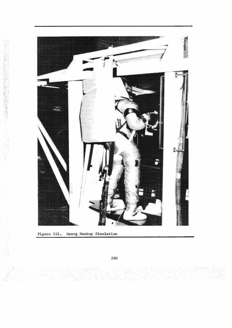
8/8/2019 MSFC Skylab Crew Systems Mission Evaluation
http://slidepdf.com/reader/full/msfc-skylab-crew-systems-mission-evaluation 314/397
Figure 161. One-g MockupSimulation
290
8/8/2019 MSFC Skylab Crew Systems Mission Evaluation
http://slidepdf.com/reader/full/msfc-skylab-crew-systems-mission-evaluation 315/397
In the early Wet Workshopconfiguration, using the AMas theEVAegress point, design centered around the use of telescoping boomsof various types. Becauseof the preoccupation with crew workload,early concepts were relatively highly automated. The serpentuator(Figure 162), a segmented, highly automatic system for transferingboth the crewmanand the film magazines, was considered. Althoughquite heavy and complex, it offered considerable savings in crew work-load and was, therefore, given initial emphasis. Also considered atthis time was the use of "roll up" booms (Figure 163), which formerlyhad been used principally as antennas on unmannedsatellites. At thetime of the decision to use the LM hatch as the baseline EVAegresshatch, the simpler extendible boomswere being considered for filmmagazine transfer.
Twomethods of crew transfer were under investigation: i) usingthe booms themselves, and 2) using fixed handrails on the exterior ofthe MDAand the LM/ATM. Handrails were ultimately selected for tworeasons: i) lack of sufficient bending stiffness in the boomsand2) the potential hazards related to the sharp edged tapes formingthe boomelements.
Whenthe decision was made to use the LMhatch for primary EVAegress, attention shifted to the use of rail systems of simpler designand construction than the boomor serpentuator concepts. Several"aided" rail systems, either poweredor manually controlled, wereconsidered. In addition, pivoting arms operated through a linkagewhich would swing packages to workstations were given heavy emphasis.
The initial rail system was namedthe "trolley" (Figure 164),and provided the capability to transfer both crew and film simultaneous-ly. The crewmanprovided the motive force by pulling himself and thetrolley along the rail. A prototype trolley was designed and fabricatedand was evaluated in neutral buoyancy simulation. Although the trolley
system provided excellent control of astronaut body position and couldallow simultaneous transfer of both crew and equipment, it was quitecomplex, rather heavy, and the simulations indicated considerabledevelopment would be required to provide an easy rolling system.Difficulty with this system was due to cocking in the roller systemfrom off-center loads applied by the crewman(especially in negotiatingcurves).
Helping to make the decision not to go ahead with the trolleywas the reclock of the workstations to provide a more direct line fromthe LMhatch to the LMEndWorkstation and the Sun EndWorkstation.The equipment transfer design configuration at this point cons_tedof a pivoting arm (Figure 165), actuated by a handle at the LM HatchWorkstation, which swungdownto the LMEnd Workstation with appropri-ate cameras. For the SunEndWorkstation, the S082Aand B film maga-zines were to be carried on a rail device, nicknamed the "skateboard",which rolled on the dual handrails provided for translation to the sunend. Twoconcepts of the skateboard were pursued initially. One couldbe pushed in front of and actuated by the crewman. Another concepthad a simple cable system operated by a handcrank at the LMHatchWorkstation, allowing transfer of the equipment separately from thecrewmantranslating to the sun end.
291
8/8/2019 MSFC Skylab Crew Systems Mission Evaluation
http://slidepdf.com/reader/full/msfc-skylab-crew-systems-mission-evaluation 316/397
-__ii_ i_Iilr!/_ii_i_!_i_,I__ii_i,i _i _ _ ,k
ao_n_u_da_s "Z91 _anS_
Cq
¢q
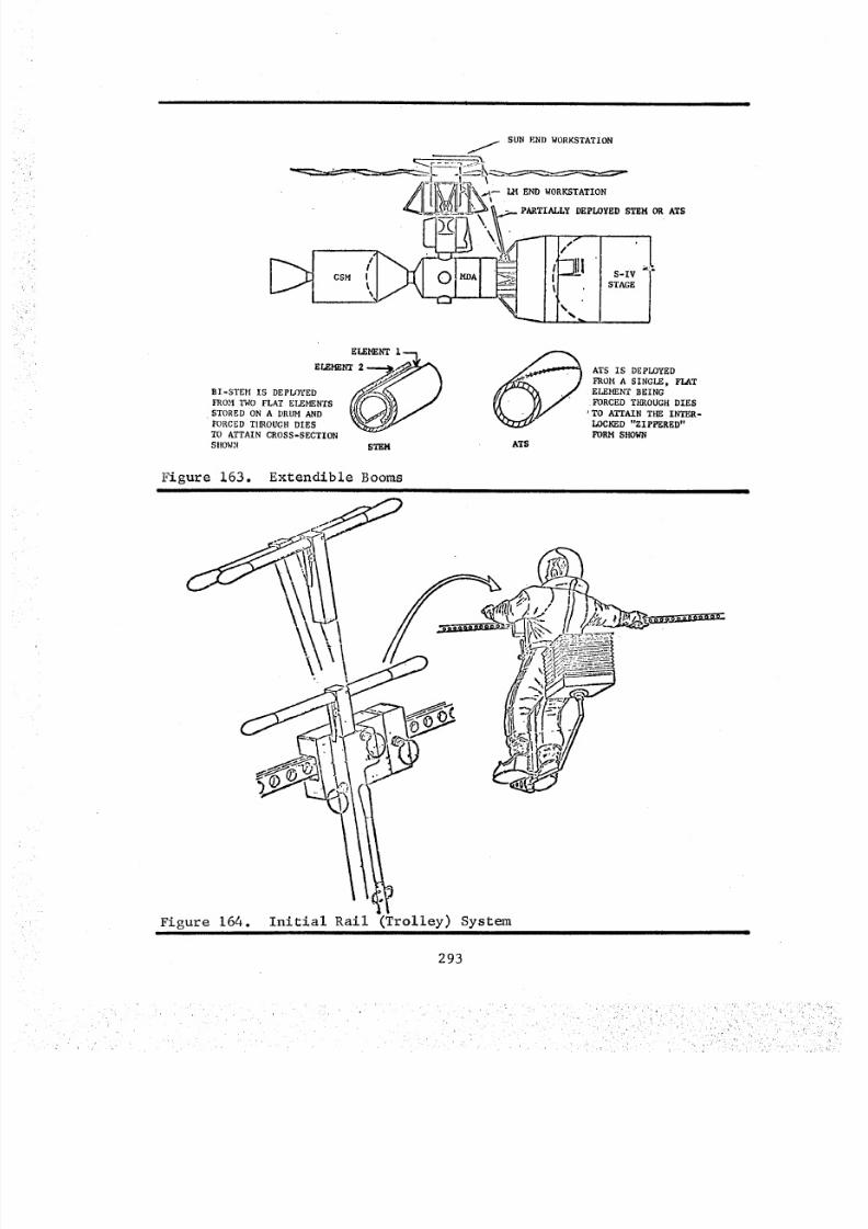
8/8/2019 MSFC Skylab Crew Systems Mission Evaluation
http://slidepdf.com/reader/full/msfc-skylab-crew-systems-mission-evaluation 317/397
SUN E ND WO RK STAT IO N
' ENDO. TA ION
%
_ _SM [ S-IV
E_ I--1.
E_ 2__BI'STEM IS DEPLOYED /y/_<khk 2?
FROM TWo FLAT ELEMENTS [[[[ _ /
STORED ON A DRUM AND %_y/]/
FORCED T[nRODGH DIES %_/,_
TO ATTAIN CROSS-SECTION
SHOWN STEM
ATS IS DEPLOYED
FROM A SINGLE, FLAT
ELEMENT BEING
I FORCED THROUGH DIES' TO ATTAIN THE INTER-
LOCKED "ZIPPERED"
;ORM SHOWN
AT$
Figure 163. Extendible Booms
Figure 164. Initial Rail (Trolley) System
293
;r •
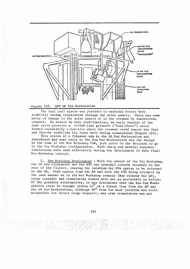
8/8/2019 MSFC Skylab Crew Systems Mission Evaluation
http://slidepdf.com/reader/full/msfc-skylab-crew-systems-mission-evaluation 318/397
LM FILM (
/----LMA FORWARO HATCH
SUN END FILM
TRANSPORTATIONDEVICE
I_SKATEBOARD #
LM ENO FI LM
TRANSPORTATIONOEVICE
iJ !'i :: e,_SUN END
TRANSLATIONRAILS
NFigure 165. ATM I_M End Workstation
The dual rail system was provided to maintain better body
stability during translation through the solar panels. There was some
worry of damage to the solar panels or to the crewmen by inadvertent
contact. To assist in body stabilization, an early concept of the
dual rails provided a trough-like gridwork ("Coal-Chute") whichformed essentially a key-slot where the crewman could insert his feet
and thereby stabilize his lower body during translation (Figure 165).This system of a flipover arm to the LM End Workstation and
skateboard and dual rails to the Sun End Workstation was the design
at the time of the Wet Workshop CDR, just prior to the decision to go
to the Dry Workshop configuration. Both one-g and neutral buoyancy
simulations were used effectively during the development of this final
Wet Workshop concept.
2. Dry Workshop Development - With the advent of the Dry Workshop,the LM was eliminated and the ATM was launched already attached to the
rest of the Cluster, causing the location for EVA egress to be returned
to the AM. With egress from the AM and with the ATM being oriented in
the same manner as in the Wet Workshop concept (but without the LM),
cargo transfer and translation routes were not as accessible as before.
Of the possible alternatives, it was determined that the Sun End Work-
station could be brought within 45 ° of a direct line from the AM and
the LM End Workstation, although 90 ° from the best location was still
accessible for direct cargo transfer, and crew translation was not
294
8/8/2019 MSFC Skylab Crew Systems Mission Evaluation
http://slidepdf.com/reader/full/msfc-skylab-crew-systems-mission-evaluation 319/397
seriously hampered. Under Dry Workshop design, the LM End Workstation
of the A_M was renamed the Center Workstation (with the acronym VC)
and the Sun End Workstation was given the acronym VS (in keeping withthe JSC selection of two letter nomenclature for all external work-
stations). The Dry Workshop film retrieval concept resulted in the
development of a workstation in the fixed airlock shroud area, (Figure166), designated VF. This station would be occupied by the first
crewman out during an EVA. It would provide stowage locations for all
the ATM film, a temporary stowage hook for equipment, sufficient hand-
rails for use of the foot restraints, general mobility in the area of
the workstation, and access to whatever transfer equipment was to be
provided. Thus, one crewman was to provide a general management role
for film equipment and umbilicals, and the other crewman was to actuallytranslate to the ATM and exchange the film.
Some initial studies considered the use of a skateboard device
for film transfer to the ATM from the fixed airlock shroud. It became
obvious, however, that any rail concepts, being discontinuous across
the ATM/MDA interface (to allow ATM deployment), faced unjustifiable
difficulties in alignment during deployment and were, therefore,dropped. Extendible booms mounted at the fixed airlock shroud and
"pre-aimed" at the ATM workstations, were next to be considered for
equipment transfer, with separate crew transfer and equipment transfer
being baselined. A simple, endless clothesline system was selected
as a back-up to the booms. The alternative of carrying film magazines,one at a time, by the crewman performing the film retrieval was consi-
dered and rejected because of the higher probability of damage to the
film magazines and the increased translational workload required.
The fixed airlock shroud workstation was developed using the
combination of one-g and neutral buoyancy mock-up hardware. Concepts
were generated in one-g and, if they appeared reasonable, were fabri-
cated and installed in the neutral buoyancy development article.
Using the combination of one-g and neutral buoyancy development, and
simulation to determine the most effective positioning for the VF foot
restraints and the best utilization of the space around the VF work-
station (again with the selection of extendible booms for film transfer)proved very effective. There were to be three booms provided: one to
the Sun End Workstation, one to the Center Workstation, and one spare.
The positions of these booms were selected initially using one-g hard-
ware. Their accessibility for replacement and for positioning at theATM workstations was then verified in neutral buoyancy simulation.
The clothesline assemblies (alternate film transfer system) weredesigned to be mounted to approximate the travel path of the booms as
closely as possible. This took advantage of the previous work done in
positioning the booms for good access to the film packages at boththe airlock and the ATM ends of the transfer. Since the VS Workstation
was not visible from the airlock and since neither selected method of
film magazine transfer would go around the corner, an intermediate
workstation named the Transfer Workstation (VT) was developed (Figure 167).
295
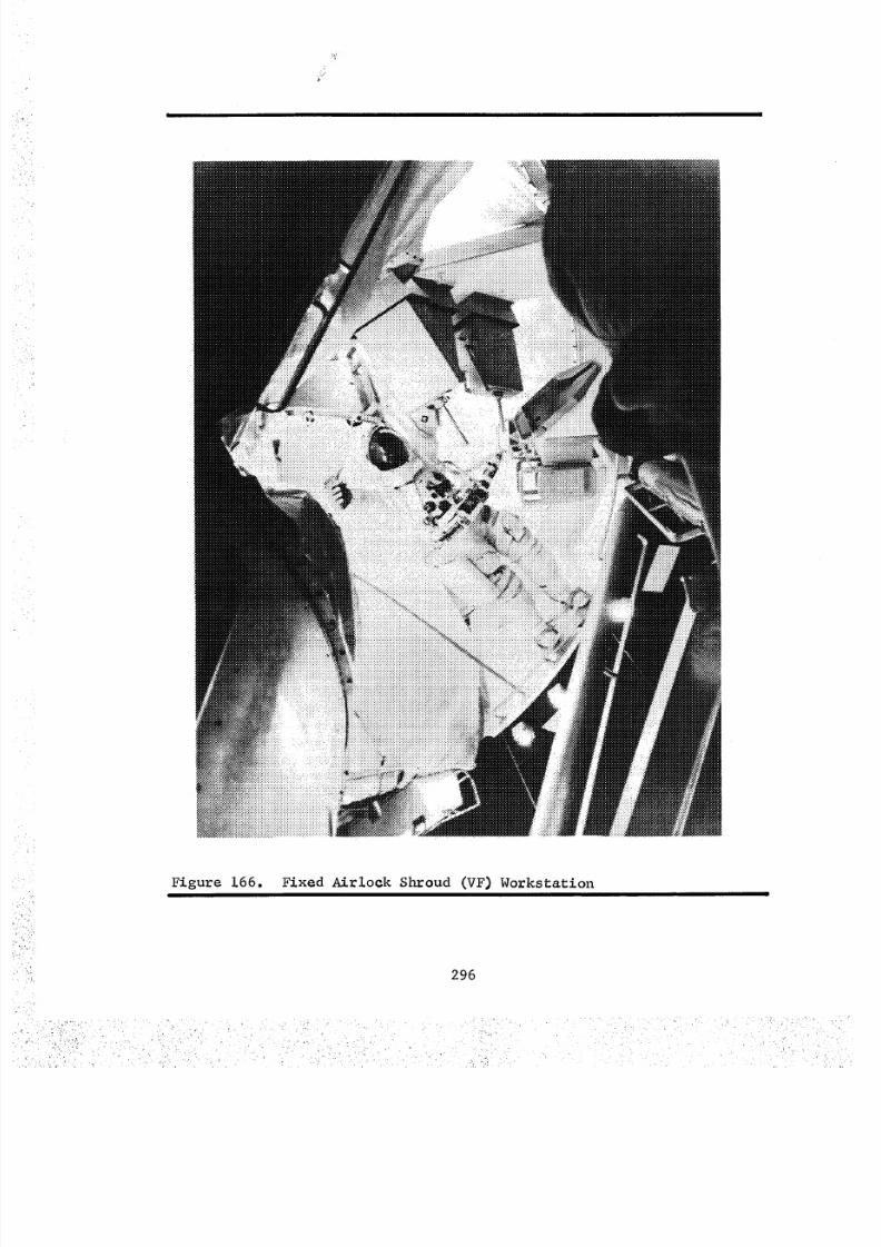
8/8/2019 MSFC Skylab Crew Systems Mission Evaluation
http://slidepdf.com/reader/full/msfc-skylab-crew-systems-mission-evaluation 320/397
Figure 166. Fixed Airlock Shroud (VF) Workstation
296
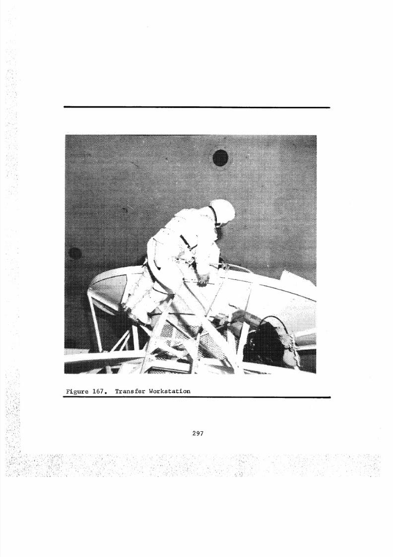
8/8/2019 MSFC Skylab Crew Systems Mission Evaluation
http://slidepdf.com/reader/full/msfc-skylab-crew-systems-mission-evaluation 321/397
\
Figure 167. Transfer Workstation
297
8/8/2019 MSFC Skylab Crew Systems Mission Evaluation
http://slidepdf.com/reader/full/msfc-skylab-crew-systems-mission-evaluation 322/397
Because of its unique location and position with respect to the other
components, this workstation was developed entirely through the use of
neutral buoyancy simulation. With the establishment of the Transfer
Workstation and the concomitant selection of the position for stowage
of the S082A and B magazines on their film transfer tree, along with
the selection and location of a temporary stowage device for the S082
cameras during film exchange, the ATM EVA system development was essenti-
ally complete. The system described above was evaluated during the
EVA CDR in November 1970 and was accepted with little modification.
3. Final Systems Development and Verification - Two major changes
to workstations occurred during final concept verification, procedures
development, and early training. The first change involved simplifi-cation of the Center Workstation and its guard rail due to the deletion
of the requirement for a mechanical lock to ensure that the canister
would not inadvertently roll while a crewman was in the process of
transferring film. It was determined that due to the design of the
canister and its drive logic this mechanical brake was not required.The second change was required when it was found that the film transfer
booms as orig_nally designed could not carry the film transfer boom
hook during launch without extensive redesign. Early vibration testing
of the booms pointed out this problem and, consequently, a quick-release
attachment to the boom was designed and a stowage box was provided nearthe VF workstation, from which the SL-2 crew could install the boomhooks.
To aid in the replacement of failed film transfer boom, a temporary
workstation, designated the replacement workstation (VR), was developed.This consisted of a handrail and a small section of aluminum channel
which served, respectively, as a toe bar and heel restraint and was
mounted near the airlock tunnel in such a position that all three of
the film transfer booms could be reached and exchanged from that position.
Umbilical clamps, which were the subject of much discussion during
the early development of the EVA, were placed at the Sun End Workstation,the Center Workstation, and in two places (one for each crewman) just
outside the EVA hatch, accessible from the VF Workstation. This was a
considerable decrease from the number of clamps originally discussed
in the early days of EVA development. Ultimately the use of the clampsat the two ATM workstations became optional at crew discretion. The
primary umbilical management position became the fixed airlock shroud
workstation (VF) with its two umbilical clamPs.
Minimal procedural changes occurred during training. This was a
result of the detailed, iterative development performed on the system
and the consistent participation by the flight crew.
4. Summary - The Skylab EVA system design was initiated at a
time when orbital EVA capabilities were not clearly known and the program,which was to become Skylab, was exhibiting considerable fluidity. These
factors encouraged the consideration of many possible design solutions.
298
8/8/2019 MSFC Skylab Crew Systems Mission Evaluation
http://slidepdf.com/reader/full/msfc-skylab-crew-systems-mission-evaluation 323/397
In particular, the changes in the EVA egress position created very
different transfer requirements, thus spawning new options with each
change. The final result was a system which had undergone thorough
evaluation of alternatives and provided a conservative, simple, and
flexible design.
Note: For further details, see MSFC TMX-64855, Skylab EVA SystemsDevelopment.
299
8/8/2019 MSFC Skylab Crew Systems Mission Evaluation
http://slidepdf.com/reader/full/msfc-skylab-crew-systems-mission-evaluation 324/397
B. ATMFilm Retrieval
The ATMexperiments, with the exception of S055, collected solarastronomy data on photographic film. This film was enclosed in maga-zines which were to be periodically removedand replaced by an EVAcrewman. The hardware described in this section includes all majorEVAequipment required for the removal and replacement of film maga-zines from the ATMexperiment canister. The EVA hardware subsystemsincluded are the Fixed Airlock Shroud Workstation (VF), the CenterWorkstation (VC), the Transfer Workstation (VT), the SunEnd Worksta-tion (VS), and the mobility aids and other equipment (EVA lights andumbilical clamps, for example) along the EVA translation path. Thehardware at these four EVAWorkstations is discussed in the sectionsbelow with regard to the hardware design, its on-orbit use, any anomaliesthat occurred during its use and an assessment of its design. Thefunctions and interrelationships of each hardware subsystem are alsoidentified.
i. Fixed Airlock Shroud Workstation _VF) - This workstation,together with the adjacent center lock compartment of the Airlock
Module, served as "base camp" for all nominal and contingency EV
operations by providing stowage locations for all hardware and tools,
prime and back-up transportation devices for A]I_ film magazines,and foot restraints from which one crewman (EVI) could monitor the
other (EV2) during Center Workstation and Sun End Workstation film
retrieval operations. Within reach of the crewman in his foot restraints
were stowage locations for the ATM film magazines, Film Transfer
Booms (FTBs), the boom hook stowage box, the boom control panel (Panel
321), Life Support Umbilical (LSU) clamps, data acquisition camera
attach points, a temporary stowage hook, clothesline film transfer
systems (back-up), and sufficient fixed handrails for ingress, egressand translation to and from other EV workstation on the cluster. Also
in the immediate vicinity were the D024 experiment, the FTB replacementworkstation (for exchanging a failed FTB with the spare), and the $230experiment.
a. Film Transfer Booms (FTB), Boom Control Panel, and Boom
Hooks - The Film Transfer Booms were tubular extendible devices, which,
under the control of EVI (using the boom control panel), were capable
of being extended to and retracted from the Center Workstation (VC)
and Transfer Workstation (VT). These were used to transport film
magazines on a clamp-type hook attached to the end of each boom. The
boom used for VC operations carried individual film magazines to alocation near the VC, so EV2 could remove spent film magazines from
the ATM canister and replace them with fresh magazines from the FTB.
The FTB used for Sun End operations transported the VS tree with both
S082A and B film magazines attached, and terminated near the TransferWorkstation where EV2 removed the tree from the boom and stowed it in
a convenient location for use from the Sun End foot restraints. The
3OO
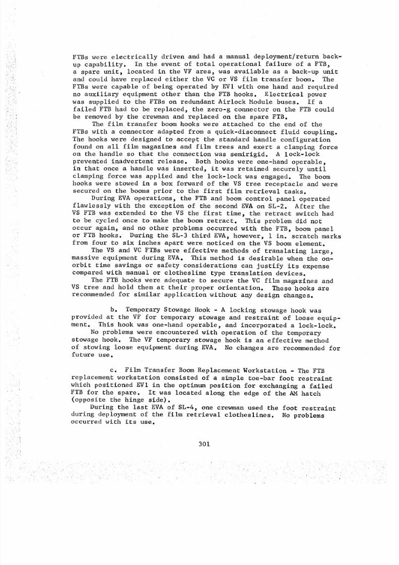
8/8/2019 MSFC Skylab Crew Systems Mission Evaluation
http://slidepdf.com/reader/full/msfc-skylab-crew-systems-mission-evaluation 325/397
FTBs were electrically driven and had a manual deployment/return back-
up capability. In the event of total operational failure of a FTB,
a spare unit, located in the VF area, was available as a back-up unit
and could have replaced either the VC or VS film transfer boom. The
FTBs were capable of being operated by EVl with one hand and required
no auxiliary equipment other than the FTB hooks. Electrical power
was supplied to the FTBs on redundant Airlock Module buses. If a
failed FTB had to be replaced, the zero-g connector on the FTB could
be removed by the crewman and replaced on the spare FTB.The film transfer boom hooks were attached to the end of the
FTBs with a connector adapted from a quick-disconnect fluid coupling.
The hooks were designed to accept the standard handle configuration
found on all film magazines and film trees and exert a clamping forceon the handle so that the connection was semirigid. A lock-lock
prevented inadvertent release. Both hooks were one-hand operable,
in that once a handle was inserted, it was retained securely until
clamping force was applied and the lock-lock was engaged. The boom
hooks were stowed in a box forward of the VS tree receptacle and weresecured on the booms prior to the first film retrieval tasks.
During EVA operations, the FTB and boom control panel operated
flawlessly with the exception of the second EVA on SL-2. After the
VS FTB was extended to the VS the first time, the retract switch had
to be cycled once to make the boom retract. This problem did not
occur again, and no other problems occurred with the FTB, boom panel
or FTB hooks. During the SL-3 third EVA, however, i in. scratch marksfrom four to six inches apart were noticed on the VS boom element.
The VS and VC FTBs were effective methods of translating large,
massive equipment during EVA. This method is desirable when the on-
orbit time savings or safety considerations can justify its expensecompared with manual or clothesline type translation devices.
The FTB hooks were adequate to secure the VC film magazines andVS tree and hold them at their proper orientation. These hooks are
recommended for similar application without any design changes.
b. Temporary Stowage Hook - A locking stowage hook was
provided at the VF for temporary stowage and restraint of loose equip-
ment. This hook was one-hand operable, and incorporated a lock-lock.
No problems were encountered with operation of the temporary
stowage hook. The VF temporary stowage hook is an effective method
of stowing loose equipment during EVA. No changes are recommended for
future use.
c. Film Transfer Boom Replacement Workstation - The FTBreplacement workstation consisted of a simple toe-bar foot restraint
which positioned EVl in the optimum position for exchanging a failed
FTB for the spare. It was located along the edge of the AM hatch(opposite the hinge side).
During the last EVA of SL-4, one crewman used the foot restraint
during deployment of the film retrieval clotheslines. No problemsoccurred with its use.
301
8/8/2019 MSFC Skylab Crew Systems Mission Evaluation
http://slidepdf.com/reader/full/msfc-skylab-crew-systems-mission-evaluation 326/397
d. VF Handrails - The VF contained sufficient handrailsto assist all required operations. Handrails were anodized blue andwere numberedto provide easy identification and correlation withchecklists. The handrails were fabricated by compressing a 1.125 in.tube to 1.42 in. X 0.62 in., and were designed to withstand a loadof 200 ibs. in any direction. They were mounted with stand-offs 3.25in. away from the mounting surface.
During EVAoperations, the crew noticed that the handrails hadturned turquoise from the original blue color. All EVA handrails wereadequate for crew stability and translation. Their use on future EVAmissions is recommended.
Although someof the EVAhandrails at the other workstations weresmaller (1.25 in. X 0.63 in.), their general configuration was thesame. Since the handrails at all EVAworkstations were basicallythe same, the commentsconcerning design description, on-orbit use,and recommendationsfor VS handrails is also applicable for handrailsat other workstations.
e. Film Trees and Receptacles - Two pallets (trees) wereused to transfer film magazines from the AMwhere they had been placedduring EVA prep., to the VF through the EVAhatch. Each tree wasinserted into a tree receptacle located within reach of the VF footrestraints. These receptacles consisted of a metal plate designedto hold the film trees. Each receptacle had a locking hole that wouldaccept a spring loaded latch on the tree's base. The VS film treesecured both S082 film magazine containers as a unit and was extendedto the Transfer Workstation on the VS film transfer boom. On theother hand, the VC tree secured the S052, S054, S056 and Hal magazinesas a cluster for handling only within and between the AM and the VF;film magazineswere transferred individually to the VC, while the treeremained in the FASreceptacle. Both the VC and VS film trees wereone-hand operable for both camera attachment/removal and tree mounting/removal.
During EVAoperations, VC and VS film trees worked satisfactorily,and no problems were encountered with the VF tree receptacles. TheATMfilm trees are convenient methods of transporting several piecesof equipment simultaneously. Positive latching of the separate hard-ware items on the tree is desirable. The film tree receptacle is aneffective method for securing the tree with a minimumof time and effort.
Since the film tree receptacle, located at the Sun End (VC), wasidentical to the receptacle at the VF, all commentsconcerning otheroperation of the VF tree receptacle apply to the VS receptacle also.
f. Life Support Umbilical (LSU) Clamps - Two spring-loadedLSUclamps were located adjacent to the EVAhatch as temporary restraintfor the Life Support Umbilical (LSU) of each crewman. Shortly aftereach crewman's egress from the lock compartment into the EVAbay, eachLSUwas inserted into a clamp with predetermined amounts of slack,depending on the activity to be performed.
302

8/8/2019 MSFC Skylab Crew Systems Mission Evaluation
http://slidepdf.com/reader/full/msfc-skylab-crew-systems-mission-evaluation 327/397
The VF LSUclamps operated satisfactorily during EVAand wereeasier to operate than they had been in the neutral buoyancy trainer.They are acceptable, as designed, for future use.
Commentsconcerning operation of the VF umbilical clamps applyto the clamps used at other workstations since they were identical.
g. EVAFoot Restraint - The EVA foot restraint located atthe VF consisted of a toe-bar and heel plate for each foot. Tosecure his feet in the restraint, the crewmaninserted each boot toeunder the toe-bar and slid the boot heel clip under the heel plate.To disengage the boot from the restraint, the crewmanslid the heelto the inside and withdrew his toe from the toe-bar. The VF footrestraint was identical to the foot restraints used at other work-stations, except for the orientation of the restraints on the mountingplate.
The foot restraints at the VF and other workstations provide anadequate crew restraint when used in combination with a handhold orhandrail. The existing foot restraint design is recommendedor futureapplications.
h. VF Area EVALights - The EVAlighting system providedillumination to the VF area by meansof five EVA lights. Primarycontrol of the VF lights as well as all other EVA lights was fromPanel 316 located in the AMlock compartment. Each light was encasedin a wire-grid enclosure to protect its light bulb from damage.
In addition to illuminating the VF area, one of the five EVA lightswas mountedon the D024 sample panel handrail to illuminate that areafor sample panel retrieval. The lighting systemwas powered by twoindependent buses with each light set capable of providing adequatelighting for all EVAoperations.
During one EVA, the lights failed to comeon when commandedromPanel 316 in the center lock compartment. Approximately i0 minutesafter sunset, when the problem had becomeevident, the lights weresuccessfully commandedn from the ground. No satisfactory cause forthis problem has been established.
Otherwise, the EVAl ights provided adequate illumination. Thelights are recommendedor use on future missions without changingthe illumination characteristics, basic design, or redundant wiringphilosophy. Glare shield configuration will depend, however, on thelocation of each light at the workstation.
Since the VF EVA lights were identical to those used at otherworkstations, the above commentsapply to all EVA lights.
i. Photographic Equipment - During certain portions of theEVAs, a 16mmdata acquisition camerawas used to obtain motion picturerecords of EVactivities. For mounting this camera, using a modifieduniversal mount, portions of several VF handrails were markedwithaluminum tape. Positions for placement of the camerawere readilyaccessible to the EVAcrewman,who mounted the camera at the beginningof someEVAs, made a film record of selected activities at the VS orVC, and recovered the camera at the end of the EVA.
303
8/8/2019 MSFC Skylab Crew Systems Mission Evaluation
http://slidepdf.com/reader/full/msfc-skylab-crew-systems-mission-evaluation 328/397
During EVAoperations, both the Data Acquisition Camera(DAC)and video cameras were difficult to mount, point, and operate. Ifcameras are to be used during future EVAs, they should have separate,firm mounting brackets located to minimize accidental contact withthe crewmanin the workstation. The crewmanshould also have adequatefoot restraints and handrails for stability. All camera operationsshould be one-handed.
j. Clothesline Film Transfer Units - Two clothesline filmtransfer units were available as back-up to a failed spare FTB andfor nominal ATMfilm retrieval during the last SL-4 EVA. Each clothes-line unit consisted of a "Brooklyn" type endless clothesline withappropriate hooks and hardware for attachment to special bracketslocated at the VF, VC and VS. In the event of the spare FTB failure,a clothesline could be manually deployed to continue film magazineremoval/replacement operations. The free end of the appropriateclothesline (VC or VS) would be carried by EV2 to the VC or VT andattached to the clothesline bracket, the other end having been attachedprior to launch. Each clothesline had two tether hooks for securingthe film magazines. Both the VC and VS clotheslines were operablewith one hand, were simple in design, and needed no special handlingequipment other than the clothesline attach brackets.
No problems occurred with the clothesline or stowage box opera-tion. However, the SL-4 crew had to be careful when ingressing theAM hatch at the end of the fourth EVA to prevent getting theirumbilicals entangled around the deployed clothesline. No changes arerecommendedor future use.
k. VC and VS Clothesline Containers - Stowage containerswere provided for the VC and VS clotheslines on the side of the FTB
housing. The containers were madeof anodized aluminum and fiberglassand had velcro fasteners to hold the cover closed. The clotheslineswere installed in the container in such a way as to provide a slightresistance to deployment, so that as EV2 (carrying the free end of theclothesline) moved from the VF to either the VC or VT, a light tensionwas maintained which prevented entanglement.
No anomalies occurred with use of the clothesline container.Similar designs may be used on future EVAmissions.
2. ATM Center Workstation (VC) - The VC provided the equipment
necessary to accomplish the task of removal and replacement of the
S052, S054, S056, and Hal film magazines. Specifically, this equipment
included Rotation Control Panel 160, experiment access doors, a clothes-
line attach bracket, EVA lights, cameras and receptacles, a protective
screen, handrails, an LSU clamp, and an EVA foot restraint, each of
which is separately discussed below.
a. Rotation Control Panel (160) - Rotation Control Panel
160 provided the means for rotating the experiment canister to positioneach of the camera access doors at the Center Workstation. Panel 160
304
8/8/2019 MSFC Skylab Crew Systems Mission Evaluation
http://slidepdf.com/reader/full/msfc-skylab-crew-systems-mission-evaluation 329/397
was also used to rotate the canister to the proper orientation forSun End EVAoperations. The S082Aand B experiment aperture doorswitch and status indicators were used to open the S082Aand B doorsfor VSoperations. The control panel hand controller provided twospeeds in each rotation direction. The handle had !40 degrees ofright or left motion with a maximumorque of 26 inch-pounds, and was
compatible with pressure suit gloved-hand operation. In order for thetranslation from "Low" to "High" speeds to be obvious, a detent camwas used. The "Roll Enable/Inhibit" switch empowereda solenoid torelease the mechanical brake on the roll drive and brake assemblywhen placed in the "Enable" position. The "Inhibit" switch positionallowed the spring loaded brake to operate at 80 foot-pounds of break-out torque. Primary and secondary power switches were used to eitherenable or inhibit redundant electrical power busses. The S082AandB aperture door switch was a three position (center-off) momentaryswitch. A five watt light in the adjacent talkbacks displayed "Open"or "barber pole" by meansof back lighting. During EVAoperations therotation control panel operated satisfactorily, and its use is recom-mendedfor future applications without modification.
b. VC EVALights - The five VC lights provided a minimumof five ft-lamberts of light. If one power bus had failed, sufficientlight would still have been available if either of the two buses hadbecomeinoperable.
Lights at the VC were adequate for all crew operations and evenprovided enough illumination for good photographs at night (see VI.B.l.h for a detailed description of the EVA lights).
c. VC Protective Screen - The VC protective screen was madefrom sheet aluminumperforated with i in. holes and prevented contactbetween the ATMgimbal rings and canister launch lock arms and the
crewman's legs and feet during canister rotation. A standard crosssection handrail along the edge of the screen at waist level added tothe complementof handholds at this workstation.
The screen kept the crewmenawayfrom the canister roll ring andother canister-mounted equipment. No interference or significant lossof mobility due to the screen was evident for nominal EVoperations(film retrieval). For one of the contingency operations, however,absence of this screen mayhave been preferable.
A screen is acceptable for separating the crewmanfrom dangerousor delicate hardware. However, if this hardware has to be examinedor serviced, the screen should be removable or hinged to provide access.
d. VC Clothesline Attach Bracket - The VC clothesline attachbracket incorporated the VC temporary stowage hook and was mounted ona boomlocated to the right of the VC. The boomwas manually deployedfrom its launch position (where the clothesline attach point andtemporary stowage hook were inaccessible) to any one of three deployedpositions at the option of the crewman. This allowed the crewmentooptimize the clothesline and temporary stowage hook positions accordingto their height variations.
305
8/8/2019 MSFC Skylab Crew Systems Mission Evaluation
http://slidepdf.com/reader/full/msfc-skylab-crew-systems-mission-evaluation 330/397
This bracket was deployed on SL-2. No problems occurred with its
operation. The clothesline boom is acceptable for future use as
designed. This is the attach bracket of choice, given compatible space-craft structure.
e. VC Film Access Doors - There were five doors in the side
of the canister. Four doors were provided for film retrieval by thecrew during EVA from the Center Workstation. The fifth door was forground access to the S055A experiment only. The canister was rotated
into position using Rotation Control Panel 160. The doors were all
manually operated and had no remote position indication. The S052
door was a double door with a latching mechanism on one side and a
fixed handle on the other. All doors incorporated a launch lock
mechanism, mechanical latch mechanism, door position indicator (white
flag), magnetic latches, and rim seal. The door was opened by pushingthe handle into a dust boot, which rotated a bellcrank and retracted
two latch dogs. The mechanism included a spring loaded launch lock
pin (in shear) to hold the latch dogs in the locked position. The
launch lock release was a spring loaded D-handle which was actuated
by pulling and folding the latch into a retention spring. The door
had to be pulled open against magnetic latches at the top and bottom
of the door. A friction device kept the door open, using the friction
of a spring against a curved rod. When the door was opened, a spring
loaded pin in the doors "Closed" indicator was released allowing thewhite flag to drop into the housing, out of view. With the door
closed, the pin was depressed and the flag was made visible indicating"Door Closed". Pulling out the handle rotated the bell-crank in the
opposite direction, forcing the latch pins outward into holes in thedoor sill.
All VC film access doors operated as expected with one exception.
During SL-2, the mechanical latches on the S054 door would not engage,so the door was held closed by only the magnetic latches. When the
SL-3 crew first used the door, however, the mechanical latches were
reported to be engaged. All other door operations were nominal.
The film access doors were marginally acceptable. In the original
door design, the magnetic latches were intended as the primary orbitaldoor retention devices; the white flags serving only to indicate firm
closure of the door. The latch dogs and push-pull handle operation
were designed for launch retention only; the only orbital use beingthe first "push-to-unlock" operation on the first EVA.
When the capability of the magnetic latches to withstand dockingtransients was questioned later in the program, the latch was modified
to permit re-use on-orbit but retained the "easy to unlock, but diffi-cult to relock features inherent in the basic design.
306
8/8/2019 MSFC Skylab Crew Systems Mission Evaluation
http://slidepdf.com/reader/full/msfc-skylab-crew-systems-mission-evaluation 331/397
Future programs might benefit from the following guidelines:eMagnetic, or friction latches, maywell be sufficient
for orbital use depending on docking loads, etc.• "First-line" mechanical latches, even if intended only
for launch, should be designed for re-use as though
intended for nominal orbital use.e"Second-line" mechanical latches (lock-locks, launchpins, etc.), if required only for launch, may bedesigned for "one-time only" use.
f. VCFilm Magazines and Receptacles - The film magazineswhich were used at the VCwere the S052, S054, S056, and Hal magazines.Each film magazine could be mounted into the ATMcanister receptaclewith one hand, and each magazine/receptacle incorporated visual andtactile feedback of position and locked status. Such things as align-ment stripes, flags, positive detents and end of travel hard-stops,were used in various combinations. Magazine/entry guides were includedto provide a self-align function thus reducing the requirement forfine alignment on the part of the pressure suited crewman. Presenceof these guides also served to prevent contact with more delicateportions of the experiments.
No problems occurred with installation of the film magazines intothe experiment receptacles or with their removal after the film was
• used. All of the film magazines and receptacles are acceptable forfuture use.
g. VC Foot Restraint - The EVA foot restraint used at the
VC was similar to the restraint used at the VF, and all earlier
comments concerning the VF foot restraint apply also to the VC foot
restraint. The individual boot restraints were identical; the align-
ment of each boot, however, positioned the crewman slightly counter-clockwise (in roll) in order to center him for the leftward-biasedmovements required at the VC.
The foot restraints provided adequate crew restraint during allVC tasks.
h. VC Handrails - Handrails located at the VC include the
solar panel back-up structure handrail, protective screen handrails,the outrigger hairpin handrail, and the lateral handrail. See VI. B.
i. d for a detailed description of the EVA handrails.
The handrails were adequate to provide crewman stability at theVC. Their use on future mission is recommended.
i. LSU Umbilical Clamp An umbilical clamp identical to
the one located at the VF was provided at the VC for umbilical manage-ment.
The VC LSU clamp operated adequately. One crewman did not use
the LSU clamp at the VC, but encountered no entanglement problems.
307
8/8/2019 MSFC Skylab Crew Systems Mission Evaluation
http://slidepdf.com/reader/full/msfc-skylab-crew-systems-mission-evaluation 332/397
3. ATM Sun End (VS) and Transfer (VT) Workstations - The VT was
included as a part of the Sun End Workstation (VS) and contains no
separate equipment, except for the standard EVA foot restraint. Sincethe VS is "around-the-corner" from the VF and therefore inaccessible
to the boom, the VT served to bridge this gap by providing a positionfor acceptance of the Sun End film magazines. Prior to the Sun End
film removal and replacement operations, EV2 ingressed the VT andreceived the loaded VS tree from EVI via the Sun End boom. EV2 then
placed the tree in a receptacle located on the ATM solar shield.
The VT was also used for deployment of the VS clothesline attach
bracket and clothesline during SL-4.
The VS was provided to support removal and replacement of the
S082A and B film magazines at the ATM Sun End. Equipment located at
the VS included the S082A and B experiment access doors, handrails,
EVA lights, and the S082 film magazine temporary stowage container,
the VS clothesline bracket, the VS foot restraint platform, and theS082A and B cameras and receptacles.
a. VT and VS EVA Lights - One EVA light was used at the VT
and six were used at the VS. The lights are physically identical to
those located at the VF and CC. See paragraph VI.B.I.h for a
detailed description of the EVA lights and their on orbit operation.
b. Temporary Film Stowage Container - The S082A and B
temporary stowage container was a box like unit with four flexible
retaining flaps, and was used to secure the unexposed S082 film maga-
zines while the exposed film magazines are removed from the experimentreceptacle and placed in the S082 containers. The S082 containers were
secured by the VS tree during VS film handling operations.The S082A and B temporary stowage container was used with no
problems. The temporary stowage box is simple, easy to use, and is
an effective method of retaining packages temporarily. Its use isrecommended for future application without modification.
c. VS Clothesline Attach Bracket - The VS clothesline attach
bracket is a two part folding boom mounted on the solar shield. The
boom was unlocked and deployed from the VT by releasing a pip-pin andswinging the boom into position where "one-time" latches held the boomin place.
During SL-4, the clothesline bracket was used to support the VS
clothesline. The only problem noted was that of a "sticky" pip-pinholding the bracket in its launch position. This stickiness which
yielded to presistent efforts, was probably due to a combination of
close tolerance fit and an awkward position.
The VS clothesline boom operated satisfactorily and, except for
the "sticky" launch lock pin, was easy to deploy. Although the weightand volume penalty paid for this particular hardware was severe, it
must be operationally recommended as acceptable for future use, atleast in the concept of a folding, deployable structure (see VC clothes-
line bracket, above). Its use is recommended on future missions.
308
8/8/2019 MSFC Skylab Crew Systems Mission Evaluation
http://slidepdf.com/reader/full/msfc-skylab-crew-systems-mission-evaluation 333/397
d. S082Aand B Film Access Doors - Film retrieval accessdoors were provided at the VS for S082Aand B. These doors could beopenedwith one gloved hand, by rotating a handle with a mushroomshaped pushbutton lock-lock. Friction hinges held the doors at anydesired point between the closed and open positions. The experimentSun End aperture doors, which in their closed position covered theaccess doors, had to have been opened from Panel 160 at the VC beforethe film access doors could be openedand the S082 film magazinesremoved.
The S082Aaccess door performed nominally. The S082Bdoor alsoperformed nominally until the second EVAof SL-3 when the crewmanhaddifficulty pulling the door from the door well after unlocking. Duringthe third SL-3 EVAthe crewmanhad to place both knees on the canistersurface and pull the handle with both hands to free the stuck door.The problem persisted throughout the other EVAsbut did not preventthe crewmenfrom opening the door. During the SL-4 fourth EVA, thecrewmanhad to place his hand inside the aperture opposite the hingeand pull the door open after exposure to the sunlight for severalminutes. This procedure had been suggested to the crew after I-Gsimulations had been performed. Possible explanations for the anomalymight be:
• Thermal warping of the door within the welloIncomplete retraction of someof the four door latches
(S082Ahad two)oAdherence of the rubber door seal caused by environmental
conditions.The S082Aand B doors are generally acceptable. Before they
are used again, however, someprecautions should be taken to preventthe sticking problem observed on the S082B. Either the hinge, latch-ing mechanism, seal configuration, or a combination of these, shouldbe modified prior to future use.
e. S082Aand B Film Magazines and Receptacles - Each filmmagazine could be inserted into the ATMcanister receptacle with onehand, and each magazine used flag indicators, detents, and hard stopsfor position and locking status. The magazines also provided alignmentarrows where needed for alignment with the receptacle. As with theVC, receptacle alignment/insertion guides eliminated fine positioningrequirements on the part of the crew.
The film magazines and receptacles are satisfactory, and theycould be used on future missions without modification.
f. S082Aand B Containers - The S082 containers were designedto provide thermal and contamination protection for the S082Aand Bfilm magazines. The film magazines were mounted in the containers,and the containers, in turn, were mounted on the VS tree. The operationof the container doors was similar to the VS access doors except thatthe handle rotation was 180 degrees instead of 90 degrees and thelock-lock was a finger tab rather than a push-button. As with other
309
8/8/2019 MSFC Skylab Crew Systems Mission Evaluation
http://slidepdf.com/reader/full/msfc-skylab-crew-systems-mission-evaluation 334/397
insertion/removal tasks, visual and tactile feedback was provided.Due to weight and volume requirements, however, alignment/insertionguides were not provided to the degree found elsewhere.
The film magazine containers operated satisfactorily. Theircurrent design is sufficient to provide thermal and contaminationprotection to film or samples during EVAoperations.
g. VT and VS Handrails - Handrails located at the VT andVS include the solar shield handrail and the VS handrail. All hand-rails were similar to those at the VF. See Section Vl. B. i. dfor a description of EVA handrails and their on orbit operation.
h. VT and VS Foot Restraints - EVAfoot restraints usedat the VT and VS are identical to the one discussed for VF operations.(Section Vl. B. l.g). All commentsconcerning on orbit operation applyto the VT and VS foot restraints also.
i. VSTree Receptacle/Tree - The VS tree receptacle was asheet metal bracket designed to accept the latching mechanismon thebase of the VS tree. The receptacle was identical to the VS treereceptacle located at the VF. All commentsconcerning operation andspecifications of the VS tree and tree receptacle located at the VFare also applicable.
4. EVA Translation Path - Astronaut translation path hardware
consisted of single handrails from the FAS Workstation (VF) to the ATM
Center Workstation, with a dual rail "ladder" to the Sun End Work-
station (VS). Each workstation was equipped with combinations of
single handrails for ingress/egress and movement about the particular
station. An EVA lighting system and umbilical clamps were included
in the translation system. These hardware items are discussed below.
All translation path handrails used the standard Apollo crosssection. Aluminum handrails were finished with blue anodize and all
stainless steel handrails were painted blue.
EVA lighting illuminated the EVA translation paths to eachworkstation to approximately 1.0 ft-Lamberts. Workstations were
generally illuminated with a 5.0 ft-Lambert level minimum. EVA
lighting was provided as follows:
AM EVA lights - five (5)
DA EVA lights - six (6)
ATM EVA lights - fourteen (14)
Each light unit used an 18.75 watt incandescent lamp. The EVA
lights were supplied by AM bus i and AM bus 2 through "EVA Lights i"and "EVA Lights 2" circuit breakers on Panel 202. Control of all
EVA lighting was provided on Panel 316 in the AM lock compartment byswitches labeled "Lighting-EVA: AM, DA, and ATM". Switch commands
were redundant. They provided AM bus I and AM bus 2 power to their
respective lights in such a manner that loss of a single bus would
disable only half of the lighting in a given area. All EVA lights
310
• _ i _ii!¸r k k r r r • , k •
8/8/2019 MSFC Skylab Crew Systems Mission Evaluation
http://slidepdf.com/reader/full/msfc-skylab-crew-systems-mission-evaluation 335/397
except those at the DA were enclosed in a wire grid and contained a
glare shield. The DA lights were enclosed in a metal box with a
hole provided for directional lighting.
Two LSU clamps were located adjacent to the EVA hatch to facili-
tate life support umbilical management during EVA. The clamps was
made up of two jaws: one fixed, the other movable. The movable jaw
was spring loaded to maintain a slight clamping force on the LSU.When not in use, the spring, being over-centered, maintained the
movable jaw in the "Open" position for easy insertion of the umbilical.
In the event that the LSU experienced side loads due to a crewman's
activity, the spring loaded jaw would open, freeing the LSU, and
preventing possible LSU damage due to its restraint in the clamp. The
LSU could also be manually released from the clamp. One LSU clampis located in each ATM workstation.
All equipment along the EVA path was designed without sharp
corners or edges which might damage the PGA in case of contact by the
crewman. All ATM equipment drawings of hardware along the EVA pathwere evaluated to verify that EVA safety consideration had been reason-
ably satisfied, and that all drawings contained statements about the
minimum radius of corners and edges, the finishing process used, the
deburring of milled edges, and the potting or buffing of screw heads.During EVA operations all translation route handrails were
adequate for crew translation. Lighting was also sufficient, and the
LSU clamps were adequate for umbilical management. This hardware maybe used on future EVA missions without modification.
311
8/8/2019 MSFC Skylab Crew Systems Mission Evaluation
http://slidepdf.com/reader/full/msfc-skylab-crew-systems-mission-evaluation 336/397
C. Solar Array System (SAS) BeamDeployment
Approximately 63 seconds after launch of Skylab i (SL-I) onMay 14, 1973, the Orbital Workshop (OWS)Micrometeoroid Shieldmalfunctioned, resulting in the loss of essentially the completeMicrometeoroid Shield and the #2 SASWing Assembly. The #i SASWingAssembly remained intact, although it was partially deployed andjammed. The loss of the Micrometeoroid Shield left the OWSwithoutadequate thermal protection, while the loss of the #2 SASWing andminimal deployment of the #i SASWing reduced the orbital assemblypower capability by about 50%. After SL-I orbit was attained and theanomaly had been investigated, an attempt was made to deploy theremaining SASWing Assembly (#I) from the ground, but this attemptfailed.
In preparation for SL-2 launch, the primary area of concern wasthe development of a thermal shield capable of reducing the extremetemperatures inside Skylab. A parallel effort was also initiated to
investigate feasible methods for the deployment of the #i SASWingAssembly. This section describes the activities performed to developthe hardware and crew procedures necessary to deploy the SASWing.
i. Standup EVA (SEVA} From the Command Module - The primary
concept for deploying the SAS Wing was to have the crewmen perform
a stand-up EVA (SEVA) from the Command Module (CM). The development
of hardware and crew procedures to perform this task and the on-orbitSEVA operations are discussed below.
2. Hardware/Procedures Development - Based on the assumption that
there was debris of some sort keeping the SAS Wing from fully deploying,
engineering personnel began developing tools for clearing away this
debris. On a recommendation by McDonnell Douglas Astronautics Co.,Eastern Division, the A. B. Chance Tool Company (of Centralia, Missouri),a manufacturer of tools for use on overhead transmission lines for
utility companies, was contacted. On May 16, an engineer from Chance
Tool Co. was flown to MSFC to demonstrate a number of tools that could
be used for clearing debris from the remaining SAS Wing. After eval-
uation of the available tools, three tools were selected for the SL-2
SEVA. These were: cable cutters, sheet metal cutters, and a two-pronged universal tool. (The sheet metal cutters had to be fabricated
by MSFC because there was no commercially available product of thedesired size.) The tools were sent to JSC for further evaluation.
Simultaneously, MSFC and JSC coordinated an effort to adapt these tools
to the poles being designed for use with the MSFC Thermal Shield, i.e.,adaptation of the tools/poles connection fittings, and handle and
leverage mechanisms.
a. SAS Deployment Analysis - MSFC and JSC also jointly
performed a detailed analysis of the problems associated with SAS
deployment and how it should be attempted. Areas of concern were asfollows:
312
8/8/2019 MSFC Skylab Crew Systems Mission Evaluation
http://slidepdf.com/reader/full/msfc-skylab-crew-systems-mission-evaluation 337/397
l
• What types of debris were preventing the SASWingfrom deploying?
eWhich of the tools selected would be best for specificcutting and prying jobs?
• What would be the most feasible approach angles forattempting to cut the debris?• If the debris were removed, what might be expected as theresult of SASWing dynamics?
• What hardware would be required for one-g and neutralbuoyancy testing?
b. Cutting Tool Concepts - While these tools were beingdesigned and developed, and the above areas of concern were beinginvestigated, two cutting tool concepts were sent to MSFCby Martin-Marietta Aerospace Corporation. One of these concepts was a nibblingtool adapter to the Lunar Drill, and the other was a concept for apair of manual cutting shears. Because of the size, weight and timerestrictions for SL-2 launch, these ideas were not given seriousconsideration.
c. Bench Review and Delivery of Selected Tools - Tool andadapter fabrication, along with the MSFCTwin Pole Sail fabrication,were completed on May 22. 1973. A combined Bench Review, Crew Compart-ment Fit and Function (C2F2) and one-g training session were conductedthat sameday at MSFC,attended by the SL-2 prime crew. Included inthis review were the tools supplied by JSC, including a "shepherd'shook" for pulling on the aft end of the SASBeam, and a "mushroom'fitting for the proximal end of the tool poles. The OWSmissionsupport mockupwas used during the training session. A prototype SASWing assembly had also been fabricated to simulate the envelope and
the bending characteristics of the actual beam fairing assembly. Thefollowing day, May 23, the MSFCTwin Pole Sail, and the MSFCand JSCSolar Array SystemWing deployment tools were shipped to KennedySpaceCenter for SL-2 Command Module stowage.
3. On-Orbit Operations - On May 25, SL-2 was launched with three
shield concepts and the SAS Wing deployment tools. The decision had
been made, prior to launch, that Solar Array System deployment would
be attempted by Command Module stand-up EVA (SEVA) if the Commanderdeemed it feasible.
a. Damage Inspection - Upon rendezvous with the Skylabcluster, a fly-around inspection of the Orbital Workshop was conducted.The following is a summary of the crew's comments based on their
initial damage inspection:
• #I SAS Wing looked good and appeared to be deployed
about 15 degrees.
• Nothing was left of the #2 SAS Wing except some protrudingtubes and wires.
• The vent module covers on the #i SAS Wing were still intact.
313
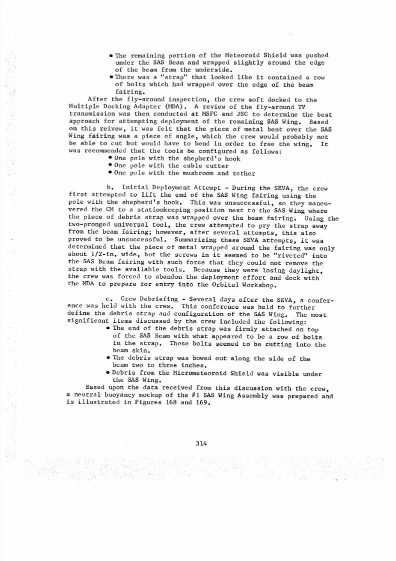
8/8/2019 MSFC Skylab Crew Systems Mission Evaluation
http://slidepdf.com/reader/full/msfc-skylab-crew-systems-mission-evaluation 338/397
• The remaining portion of the Meteoroid Shield was pushedunder the SASBeamand wrapped slightly around the edgeof the beamfrom the underside.
• There was a "strap" that looked like it contained a rowof bolts which had wrapped over the edge of the beamfairing.After the fly-around inspection, the crew soft docked to the
Multiple Docking Adapter (MDA). A review of the fly-around TVtransmission was then conducted at MSFCand JSC to determine the bestapproach for attempting deployment of the remaining SASWing. Basedon this reivew, it was felt that the piece of metal bent over the SASWing fairing was a piece of angle, which the crew would probably notbe able to cut but would have to bend in order to free the wing. Itwas reco_nendedthat the tools be configured as follows:
• One pole with the shepherd's hook• One pole with the cable cutter
• One pole with the mushroom and tether
b. Initial Deployment Attempt - During the SEVA, the crew
first attempted to lift the end of the SAS Wing fairing using the
pole with the shepherd's hook. This was unsuccessful, so they maneu-
vered the CM to a stationkeeping position next to the SAS Wing where
the piece of debris strap was wrapped over the beam fairing. Using the
two-pronged universal tool, the crew attempted to pry the strap away
from the beam fairing; however, after several attempts, this also
proved to be unsuccessful. Summarizing these SEVA attempts, it was
determined that the piece of metal wrapped around the fairing was onlyabout i/2-in, wide, but the screws in it seemed to be "riveted" into
the SAS Beam fairing with such force that they could not remove the
strap with the available tools. Because they were losing daylight,
the crew was forced to abandon the deployment effort and dock withthe MDA to prepare for entry into the Orbital Workshop.
c. Crew Debriefing - Several days after the SEVA, a confer-ence was held with the crew. This conference was held to further
define the debris strap and configuration of the SAS Wing. The most
significant items discussed by the crew included the following:
• The end of the debris strap was firmly attached on top
of the SAS Beam with what appeared to be a row of bolts
in the strap. These bolts seemed to be cutting into thebeam skin.
• The debris strap was bowed out along the side of thebeam two to three inches.
• Debris from the Micrometeoroid Shield was visible under
the SAS Wing.
Based upon the data received from this discussion with the crew,
a neutral buoyancy mockup of the #i SAS Wing Assembly was prepared andis illustrated in Figures 168 and 169.
314
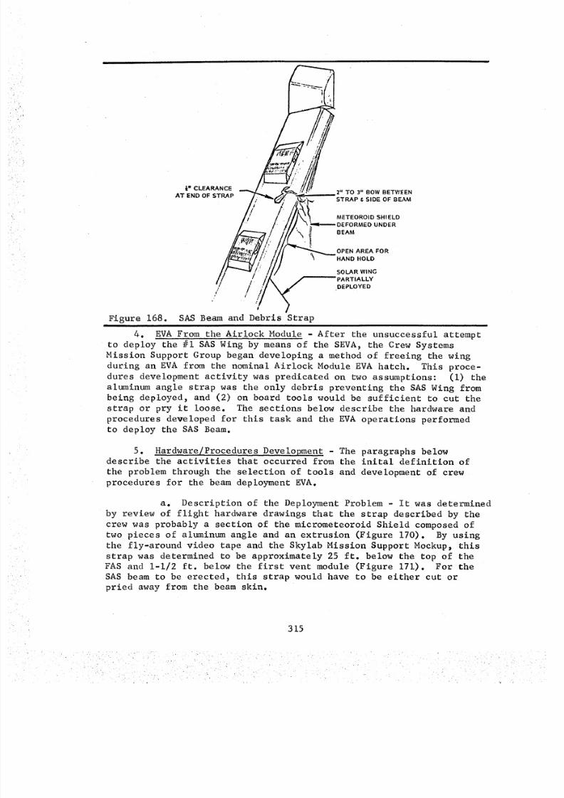
8/8/2019 MSFC Skylab Crew Systems Mission Evaluation
http://slidepdf.com/reader/full/msfc-skylab-crew-systems-mission-evaluation 339/397
_N CLEARANCEAT END OF STRAP
2" TO 3" BOW BETWEEN
STRAP & SIDE OF BEAM
METEOROID SHIELD
_ER
BEAM
OPEN AREA FOR
HAND HOLD
SOLAR WING
PARTIALLY
DEPLOYED
//.
41
, 7Figure 168. SAS Beam and Debris Strap
I
4. EVA From the Airlock Module After the unsuccessful attempt
to deploy the #i SAS Wing by means of the SEVA, the Crew Systems
Mission Support Group began developing a method of freeing the wing
during an EVA from the nominal Airlock Module EVA hatch. This proce-
dures development activity was predicated on two assumptions: (I) the
aluminum angle strap was the only debris preventing the SAS Wing frombeing deployed, and (2) on board tools would be sufficient to cut the
strap or pry it loose. The sections below describe the hardware and
procedures developed for this task and the EVA operations performed
to deploy the SAS Beam.
5. Hardware/Procedures Development - The paragraphs below
describe the activities that occurred from the inital definition of
the problem through the selection of tools and development of crew
procedures for the beam deployment EVA.
a. Description of the Deployment Problem - It was determined
by review of flight hardware drawings that the strap described by the
crew was probably a section of the micrometeoroid Shield composed oftwo pieces of aluminum angle and an extrusion (Figure 170). By using
the fly-around video tape and the Skylab Mission Support Mockup, this
strap was determined to be approximately 25 ft. below the top of the
FAS and 1-1/2 ft. below the first vent module (Figure 171). For the
SAS beam to be erected, this strap would have to be either cut orpried away from the beam skin.
315
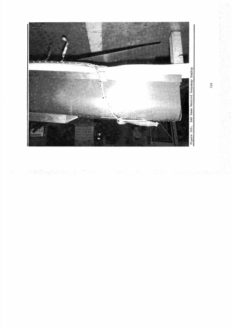
8/8/2019 MSFC Skylab Crew Systems Mission Evaluation
http://slidepdf.com/reader/full/msfc-skylab-crew-systems-mission-evaluation 340/397
oo
g_
o
T-4t_
Z
o
r_
o
00oN
',.o
8/8/2019 MSFC Skylab Crew Systems Mission Evaluation
http://slidepdf.com/reader/full/msfc-skylab-crew-systems-mission-evaluation 341/397
Figure 170.
7075 T6
Debris Strap Cross Section
I
201q TG
25.5' " ! DEBRIS "STRAP"
,_F MICROMETEOROiDSHIELD
FAS ' IU OWS
Figure 171. SAS Beam Configuration After Launch
317
8/8/2019 MSFC Skylab Crew Systems Mission Evaluation
http://slidepdf.com/reader/full/msfc-skylab-crew-systems-mission-evaluation 342/397
It was also predicted that if the strap were removed, the SASbeamwould rise approximately two feet at that point on the beamandwould then stop because of frozen oil in the damper/actuator. Thebeamwould then have to be pulled up with a force of approximately15 ibs. (measuredat beamend) to break the damper/actuator mountingbracket in the beamhinge mechanism.From the definition of the overall problem, it becameobviousthat four separate problem areas would have to be addressed:
• Translating one or two crewmanto the FASarea above theSASbeamand possibly translating one crewmanto thedebris strap
• Restraining a crewmanat the FASabove the beamand possiblyrestraining a crewmanin the strap area
• Cutting the strap or prying it loose• Pulling the beam to an erect position
In order to study the SASwing problem more accurately, the back-up SASWing was shipped from TRWto MSFC. A review of this wing wasconducted on June 2, 1973. It was learned that what were thought tohave been scratch marks on the top of the beamcaused by the debrisstrap were actually two rows of bolts. Also, two bend-relief holeswere found on the base of the vent module. These relief holes werelater selected as tether attach points for manual beamdeployment.
b. Identification of Candidate Deployment Hardware andProcedures - The four problems identified above are discussed in thissection along with hardware proposed for their solution.
(i) Crew Translation and Restraint - Two methods oftranslating to the FAS area above the SASBeamwere identified.These were: i) translation over the ATMDeployment Assembly and around
the top of the FASto the discone antenna boom, and 2) translationthrough the AMtrusses to the antenna boom. The latter appeared moreadvantageous, because several handrails and other equipment would beavailable for use as translation aids.
Several methods of translating from the FAS ring to the debrisstrap were identified, all of which involved using sometype of hand-rail from the discone antenna boomarea to the strap. These translationmethods included:
(a) Attaching four sections of the OWSirema_'spole (21-ft.) to the FAS ring with C-clamps or tethers. The crewmancould translate to the strap area and use a set of EVA foot restraintswhich had been taped to the EREPfoot restraint grid mounted to thestrap end of the fireman's pole.
(b) Translating a fully extended FTB (30-ft.)from the VF to the FASabove the strap, and attaching the FTB motorend to the FASring. The crewmancould then use the FTB as a handrailto aid him in translating to the strap.
(c) Assembling three SEVAtool poles and twospare MSFCsail poles (27-ft.) at the VF with the cable cutter on oneend and the mushroomon the other end, and then translating to the
318
8/8/2019 MSFC Skylab Crew Systems Mission Evaluation
http://slidepdf.com/reader/full/msfc-skylab-crew-systems-mission-evaluation 343/397
discone atenna area. The crewman could hook the cable cutter snugly
on the strap and use the pole as a handrail while he translated to
the strap, with the other crewman holding the mushroom end.
Methods for restraining the EVA crewmen at the FAS ring and at
the debris strap also had to be developed. The crew restraint methods
identified for the FAS ring area were:
(a) Holding the discone antenna with one hand
while placing the feet against the 02 bottles(b) Using the OWS N 2 purge line at the FAS ring
as a handhold while placing the feet on the FAS ring
(c) Attaching the OWS EVA foot restraints at the
FAS ring with C-clamps and using this as the only restraint
The first and second options had the advantage of requiring no
equipment setup. The first also had the advantage of being directly
above the strap on the SAS Beam. The third option would offer better
restraint but would require a difficult setup task.
The problem of restraining a crewman at the SAS Beam appeared to
be a more serious problem because of the possibility of sharp edges
on the debris strap and on the remaining section of MicrometeoroidShield. The problem solution was also hampered by the fact that there
was no equipment on the SAS Beam that could be used as a handhold or
foot restraint. Therefore, any crew restraint would have to be extend-
ed by the crewman at the FAS.
The restraint methods proposed for solution of this problemincluded:
(a) Use of the translation aid from the FAS ring
to the SAS Beam strap as a handhold at the strap area. This transla-
tion aid could be the fireman's pole, extended FTB, or SEVA tool poles
and sail poles. The last option had the advantage of being attached
at the strap end by mounting the cable cutter to a SEVA tool pole and
then securing the cable cutter around the debris strap.
(b) Attachment of the OWS EVA foot restraint to
the fireman's pole and letting the crewman at the debris strap use it
as a single stability aid. This method would allow use of both hands,
but it had the disadvantage of requiring ingress of the foot restraint
with no handholds. Second, it would require the EVA crewman at the
FAS ring to manage the fireman's pole with extreme care, and, finally,
the fireman's pole was only 21-ft. long, while the debris strap was
25-ft. below the FAS ring.
(2) Debris Strap Cutting/Prying Tools - Four onboard
tools were identified for cutting the debris strap or prying it loose.
These included the SEVA cable cutter, the dental kit bone saw, the pry
bar, and the SEVA universal tool.(a) Cable Cutter - The cable cutter (Figure 172)
had several significant points in its favor. First, it could be
attached to the debris strap by a crewman at the FAS, thus allowing the
other crewman to use the SEVA tool poles and sail poles as a transla-
tion aid attached at both ends. Second, the tool had a high shear
cutting force and could probably cut through the strap. Third, the
cutter could be operated remotely by one or two crewmen at the FAS ring.
319
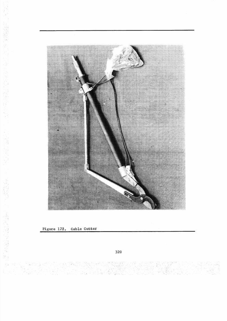
8/8/2019 MSFC Skylab Crew Systems Mission Evaluation
http://slidepdf.com/reader/full/msfc-skylab-crew-systems-mission-evaluation 344/397
Figure 172. Cable Cutter
320
8/8/2019 MSFC Skylab Crew Systems Mission Evaluation
http://slidepdf.com/reader/full/msfc-skylab-crew-systems-mission-evaluation 345/397
(b) Pry Bar - The pry bar had the advantages ofbeing simple to use, small, easily carried by a crewman,and operableone handed. However, the crewmanwouldhave to work very close to thestrap and other debris, thereby exposing his PGAto any sharp edgesthat might be present. Also, if the bolts in the strap were suffici-
ently embeddednto the SASBeamskin, the crewmanmight not be ableto generate enough force to move the strap. The strap also might springback into the SAS solar panels after being pried from the beam.
(c) Bone Saw - The dental kit bone saw, a flexiblelength of wire with rings at each end and cutting teeth bonded alongthe wire surface, had the advantage of being small and easy to carry.In addition, it was found to be a good cutting tool, provided that thecrewmancould be restrained sufficiently. The bone saw could be usedwith the crewman's thumbs in the rings at each end, or it could bemounted between two standoffs on a pole and used as a hand saw.
(d) Universal Tool - The universal tool (Figure173) could be mounted on the end of the SEVAtool poles (3) and twinsail poles (2) and could be used by the crewmanat the FAS to graspthe debris strap and pull it loose. However, this method did not workduring the SEVAand probably would not be successful during anotherEVA.
(e) Urine Separator Saw- Another concept evaluatedwas the electric motor from the urine separator adapted to a flattenedM512sample disc with edges filed and shaped into saw teeth. Thismodified tool was found to be capable of cutting the metal strapretaining the SASWing, but it would require electrical power. In thelight of the availability of other cutting devices (bone saw, cablecutter) it was not given serious consideration beyond this point.
(3) Manual SASBeamDeploymentMethods - Twoprimary
methods of deploying the SASBeamafter the strap was cut were identified.These involved: I) pulling the beamup with a tension line, or 2)forcing the beamup by placing an OWSwashcloth squeezer bag under thebeamand inflating it with the portable H20 tank (filled with N2)These methods are discussed below.
(a) Use of a Tension Line - This method of deploy-ing the SASBeaminvolved very little hardware and procedural complexity.This method is described in the steps below:
• Prepare tension line and two waist tethers as shown inFigure 174 (IVA operation).
• Affix end of line to A-frame crossmember above disconeantenna boom area.
• Translate to first vent module on SAS Beam.
• Install two waist tether hooks into relief holes in bottomof vent module (Figure 175).
• Pull line snug at A-frame end using the cleat on the apexhook (Figure 174).
• Place feet on SAS Beam forward fairing (near hinge) and lift
line until damper bracket breaks and beam deploys (Figure 176).
321
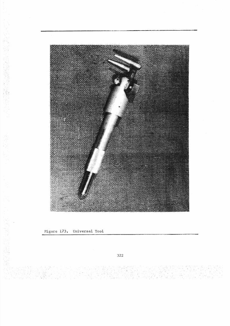
8/8/2019 MSFC Skylab Crew Systems Mission Evaluation
http://slidepdf.com/reader/full/msfc-skylab-crew-systems-mission-evaluation 346/397
Figure 173. Universal Tool
322

8/8/2019 MSFC Skylab Crew Systems Mission Evaluation
http://slidepdf.com/reader/full/msfc-skylab-crew-systems-mission-evaluation 347/397
APOLLOSMALL HOOK
•_ ' ,31' 10" _ /TYP 2 PLACES)
PBI FROM
SEVA SAIL SEVA SAIL •
CLOTHESLINE i
APEX H OOKAT ATM I
CONNECTION
/ T,ELOOP " II 37.5"
/CLEAT OR PB, FROM ' /_I_HIS • I/ + f// SNUBBING SEVA SAI L (_ I
_____------"__: ..':,-"" ' ' ' %>
(
SAS Deployment Tether/Harness - Part of EVA Prep=
Figure 174.l=
i i
i,_llcll_rrllollolil lll.lui ,-_
i I!=i' ill!I illl
Figure 176. SAS Beam Deployment Configurationi
323
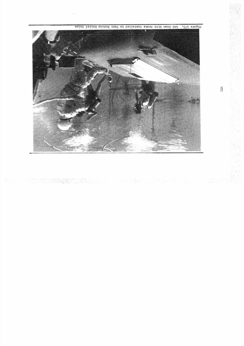
8/8/2019 MSFC Skylab Crew Systems Mission Evaluation
http://slidepdf.com/reader/full/msfc-skylab-crew-systems-mission-evaluation 348/397
8/8/2019 MSFC Skylab Crew Systems Mission Evaluation
http://slidepdf.com/reader/full/msfc-skylab-crew-systems-mission-evaluation 349/397
(b) Use of OWS Squeezer Bag - A second method
of deploying the SAS Beam involved using the OWS washcloth squeezer
bag inflated with nitrogen from the portable water tank. This involved
the IVA tasks of pressurizing the gas side of the portable water tank
to 35 psia from the pressure panel on the water bottle ring in the
OWS and attaching the 25 ft. condensate dump hose and the 15 ft.condensate tank vacuum hose between the squeezer bag and the water
tank. The EVA procedures necessary to deploy the SAS Beam by thismethod included:
e Install folded bag under SAS Beam near hinge; retreat toFAS ring.
• Crack valve on water tank to pressurize bag.• Observe SAS movement and close valve as soon as release is
assured.
The squeezer was tested and found to be capable of exerting enough
force to break the damper bracket and deploy the SAS Beam. However,
it involved complex crew procedures and detailed equipment setup.
c. SAS Wing Deployment Test Program
(i) Neutral Buoyancy Testing - The first neutral
buoyancy test run was made on May 29, 1973, to evaluate the two
candidate translation routes and to verify the distance to the SAS
debris area using the three tool poles and two sail poles with thecable cutters attached.
The second neutral buoyancy run was made on May 30, 1973, using
the SEVA hook, cable cutters and the same five pole sections. The
cable cutters were determined to be a good method of restraining thepole at the debris strap. The other end could also be restrained witha tether to the discone antenna bracket. The discone antenna boom
provided a restraint for a suited subject with his waist tether
attached to the antenna bracket. The run went well; more study wasrequired, however, on tool/equipment transfer from the nominal EVA
FAS work area to the discone antenna area.
On May 31, 1973, two neutral buoyancy runs were performed to
evaluate crew translation and restraint and strap cutting methods.
Two FAS work areas were studied: the N 2 Purge Line (upper EVA Bay)
and the discone antenna area. The discone antenna work area proved
more feasible. A flight bone saw was used to cut the debris strap in
approximately three minutes. Restraint of the crewman at the SAS work
area and hardware logistics presented the biggest problems.
During the debriefing it was decided that the particular method
for removing the debris strap should be left to the real-time judgment
of the SL-2 crew (pry bar, cable cutters or bone saw). It was alsosuggested that the crew translate under the DA trusses from the VF to
the discone antenna over the thermal capacitor using the Molecular
Sieve duct for a handrail, and then using one of the two manual deploy-ment methods for deploying the SAS Beam if the damper/actuator wasfrozen.
325
8/8/2019 MSFC Skylab Crew Systems Mission Evaluation
http://slidepdf.com/reader/full/msfc-skylab-crew-systems-mission-evaluation 350/397
Another neutral buoyancy run was conducted on June i, 1973, tostudy various debris removal tools and the manual SASBeamdeploymentmethod.
On June 2, the neutral buoyancy SASsimulation hardware wasreconfigured based on information received from the crew debriefing onJune i, and on review of the flight back-up SAS (shipped to MSFCfromTRW).
An EVAHardware/EquipmentBenchReview and EVAprep was alsoheld at the Neutral BuoyancySimulator. A suited simulation run wasmadethat afternoon with two Skylab crewmenas subjects. PreliminaryEVAcrew procedures were used, and translation of crewmenand equipmentwent muchmore smoothly. The cable cutters with five pole segmentsand mushroomhead were then the prime method for translating the SASwork area. Cable cutters were attached to the debris strap and themushroomend was tethered to the discone antenna bracket at the FASwork area. It was noted that more work was neededon methodsofcrew restraint and EVApreparation. Total EVAtime was approximately
2 hours, 25 minutes.OnJune 3, 1973, another bench review was held with the Skylabcrewmendoing their ownEVApreparation, subsequent to which the finalneutral buoyancy simulation run was madeusing near final EVAprocedures.The suited run went smoothly. Equipment and hardware transfer was wellexecuted. The crew debriefing on June I, and review of the flightbackup SASWing provided data that was used to develop better crewrestraints at the debris strap work area. Attaching the cable cuttersto the debris strap was successful on the second attempt. The crewmantethered himself to the cutting pole with a chest tether during trans-lation while taking the PBI tether (BET) which he attached to the twoaft corners of the vent module (bend-relief cutouts). The other endwas attached to the discone antenna launch support truss on the deploy-ment assembly. The crewman's chest tether, attached to the cutterpole, provided adequate restraint during translation. Restraint atthe work area was provided by the waist tether remaining attached tothe cutting pole and using the BETas a handhold after being attachedto the relief cutouts in the aft corners of the vent module. The threedebris removal tools (cable cutters, pry bar and bone saw) were used,and it was decided that the tool chosen for debris removal would be areal-time option of the SL-2 crew.
(2) One-g Testing - On June i, 1973, a SASBeamdeploy-ment test was conducted to verify that a crewmancould exert enoughforce on a tension line to break the deployment bracket in the beamhinge. The SASBeammockupwas held by a support stand on the hingeend and by a counterbalance/pulley system on the other (Figure 177).A tension line, fabricated of SEVAclothesline (PBI), was attached tothe vent module and a fixed point that simulated the discone antennalaunch tray. A load cell was mounted in the line to record the tension,
During the test, the bracket broke at 167 ibs of tension which waslower than the maximumension (309 ibs) that the suited crewmancouldgenerate.
326
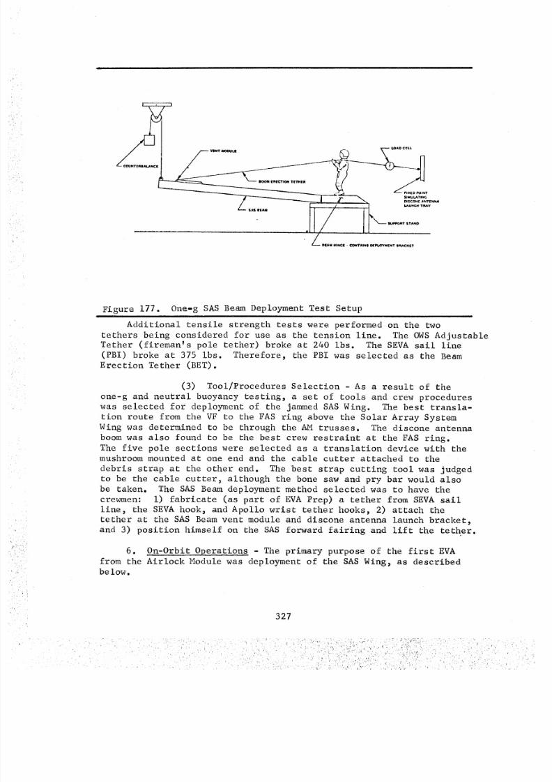
8/8/2019 MSFC Skylab Crew Systems Mission Evaluation
http://slidepdf.com/reader/full/msfc-skylab-crew-systems-mission-evaluation 351/397
Figure 177. One-g SAS Beam Deployment Test Setupi
Additional tensile strength tests were performed on the two
tethers being considered for use as the tension line. The OWS AdjustableTether (fireman's pole tether) broke at 240 ibs. The SEVA sail line
(PBI) broke at 375 ibs. Therefore, the PBI was selected as the Beam
Erection Tether (BET).
(3) Tool/Procedures Selection - As a result of theone-g and neutral buoyancy testing, a set of tools and crew procedures
was selected for deployment of the jammed SAS Wing. The best transla-
tion route from the VF to the FAS ring above the Solar Array System
Wing was determined to be through the AM trusses. The discone antenna
boom was also found to be the best crew restraint at the FAS ring.The five pole sections were selected as a translation device with the
mushroom mounted at one end and the cable cutter attached to the
debris strap at the other end. The best strap cutting tool was judged
to be the cable cutter, although the bone saw and pry bar would also
be taken. The SAS Beam deployment method selected was to have the
crewmen: i) fabricate (as part of EVA Prep) a tether from SEVA sail
line, the SEVA hook, and Apollo wrist tether hooks, 2) attach the
tether at the SAS Beam vent module and discone antenna launch bracket,
and 3) position himself on the SAS forward fairing and lift the tether.
6. On-Orbit Operations - The primary purpose of the first EVA
from the Airlock Module was deployment of the SAS Wing, as describedbelow.
327
8/8/2019 MSFC Skylab Crew Systems Mission Evaluation
http://slidepdf.com/reader/full/msfc-skylab-crew-systems-mission-evaluation 352/397
SASBeamdeployment was accomplished with very little deviationfrom the procedure sent to the crew. Equipment setup (IVA) and poleassembly (EVA) were performed without any problems or changes to therecommendedprocedures. Translation to the discone antenna boomalsopresented no problems. Attachment of the cable cutter to the debrisstrap was difficult and required several attempts. However, this hadbeen expected due to the similar difficulty encountered during theneutral buoyancy tests. The Commanderranslated to the debris straparea, and attached one BEThook to the vent module relief hole withmoderate difficulty. He was unable to attach the second hook. Inanticipation of this problem, "figure-eight" knits had been tied inthe harness portion of the BETon either side of the loop forming theend of the main tether (see Figure 174). This eliminated the require-ment to have both tether hooks attached to the vent module. Lie thenreturned to the FASarea.
Cutting the debris strap with the cable cutter provided someexciting moments. With both crewmenat the FAS, the Science Pilotattempted to pull the cable cutter rope to cut the debris strap.After several pulls, the cutter jaws appeared to be spreading withoutcutting the strap. The Commander,therefore, decided to translate tothe debris strap to examine the cutter jaws. Upon his reaching thecutter scissors mechanism,however, the cutter severed the strap. Whenthis occurred, the cutter camefree from the strap; the SASBeamcameup about two feet, and the BETbecameslack. This obviously resultedin an unstable restraint situation for the Commander. He, therefore,grabbed the BETand pulled himself to the FASwhile performing"whifferdills" along the way. Although this particular operation wasnot anticipated, it did not result in damageto the crewmenor hard-ware, but it did prevent the crewmenfrom observing the initial SASBeamrelease.
The crewmenpulled the slack from the BeamErection Tether (BET),and attempted to pull the SASBeamup by pulling on the BETfrom theFAS. Whenthis was unsuccessful, the Commanderranslated to theSASBeamhinge and lifted the BETto his shoulder facing the FAS. Atthis point, the Science Pilot was also pulling the BET from the FAS.Whenboth crewmenwere applying significant force to the BET, the beamreleased causing slack in the BET. As both were using the BET for arestraint, this resulted in another unstable restraint condition. Thiswas no serious problem, however, and they were soon restrained at thediscone antenna boomarea, but without benefit of having observed thebeamdeployment.
The return to the VF and disassembly and stowage of the SASdeployment hardware in the Airlock Module went according to the proce-dures with no difficulty.
Because this EVA is obviously not planned for other Skylab missions,the crew did not commenton improvements that could be madeto the SASBeamdeployment equipment or procedures. They did_ however, recommenda change in the EVAchecklist regarding the Airlock Module fire sensors.Whenthe sun shone in the AM aft lock compartment, the fire sensors wereactivated. This caused serious concern to the Pilot during the EVA.Therefore, the crew recommendedhat these sensors be deactiviatedduring future EVAs.
328
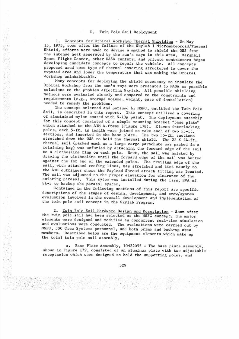
8/8/2019 MSFC Skylab Crew Systems Mission Evaluation
http://slidepdf.com/reader/full/msfc-skylab-crew-systems-mission-evaluation 353/397
D. Twin Pole Sail Deployment
i. Concepts for Orbital WorkshoR Thermal Shielding - On May
15, 1973, soon after the failure of the Skylab i Micrometeoroid/ThermalShield, efforts were made to devise a method to shield the OWS from
the intense heat generated by the sun's rays in this area. MarshallSpace Flight Center, other NASA centers, and private contractors began
developing candidate concepts to repair the vehicle. All conceptsproposed used some type of thermal covering structured to cover the
exposed area and lower the temperature that was making the OrbitalWorkshop uninhabitable.
Many concepts for deploying the shield necessary to insulate the
Orbital Workshop from the sun's rays were presented to NASA as possible
solutions to the problem affecting Skylab. All possible shieldingmethods were evaluated closely and compared to the constraints and
requirements (e.g., storage volume, weight, ease of installation)needed to remedy the problems.
The concept selected and pursued by MSFC, entitled the Twin Pole
Sail, is described in this report. This concept utilized a covering
of aluminized mylar coated with S-13g paint. The deployment assembly
for this concept consisted of a simple mounting bracket "base plate"
which attached to the A_M A-frame (Figure 178). Eleven interlockingpoles, each 5-ft. in length were joined to make each of two 55-ft.
sections, and inserted in the base plate. The two 55-ft. sections
stretched down the OWS to hold the thermal shield. The 22 X 24-ft.
thermal sail (packed much as a large cargo parachute was packed in a
retaining bag) was unfurled by attaching the forward edge of the sail
to a clothesline ring on each pole. Next, the sail was hoisted bydrawing the clothesline until the forward edge of the sail was butted
against the far end of the extended poles. The trailing edge of the
sail, with attached reefing lines, was stretched and tied tautly tothe ATM outrigger where the Payload Shroud attach fitting was located.
The sail was adjusted to the proper elevation for clearance of the
existing parasol. This sytem was installed during the first EVA ofSL-3 to backup the parasol system.
Contained in the following sections of this report are specific
descriptions of the stages of design, development, and crew/systemevaluation involved in the overall development and implementation of
the twin pole sail concept in the Skylab Program.
2. Twin Pole Sail Hardware Design and Description - Soon after
the twin pole sail had been selected as the MSFC concept, the major
elements were designed and modified as concurrent real-time simulation
and evaluations were conducted. The evaluations were carried out by
MSFC, JSC Crew Systems personnel, and both prime and back-up crew
members. Described below are the equipment elements which make upthe total twin pole sail assembly.
a. Base Plate Assembly, IOM22055 - The base plate assembly,
shown in Figure 179, consisted of an aluminum plate with two adjustable
receptacles which were designed to hold the supporting poles, and
329
i ,ii!__ , _
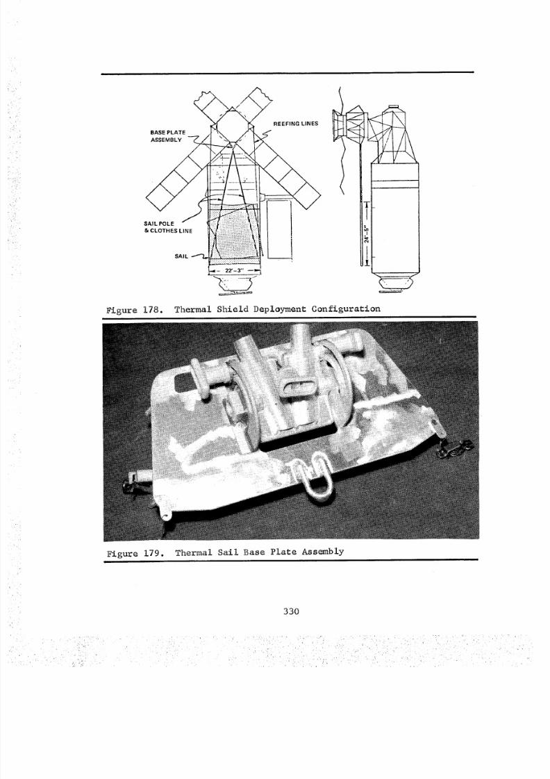
8/8/2019 MSFC Skylab Crew Systems Mission Evaluation
http://slidepdf.com/reader/full/msfc-skylab-crew-systems-mission-evaluation 354/397
BASE PLATE
ASSEMBLY
SAIL POLE
& CLOTHES LINE
SAIL
Figure 178.
REEFING LINES
Thermal Shield Deployment Configuration
Figure 179. Thermal Sail Base Plate Assembly
330
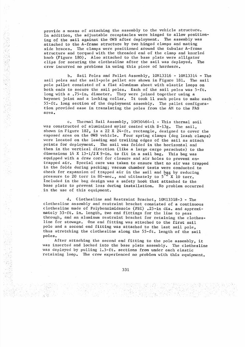
8/8/2019 MSFC Skylab Crew Systems Mission Evaluation
http://slidepdf.com/reader/full/msfc-skylab-crew-systems-mission-evaluation 355/397
provide a means of attaching the assembly to the vehicle structure.In addition, the adjustable receptacles were hinged to allow position-
ing of the sail against the OWS after deployment. The assembly wasattached to the A-frame structure by two hinged clamps and mating
side braces. The clamps were positioned around the tubular A-framestructure and torqued with the threaded end of the clamp and knurled
knob (Figure 180). Also attached to the base plate were alligator
clips for securing the clothesline after the sail was deployed. The
crew incurred no problems in using this piece of hardware.
b. Sail Poles and Pallet Assembly, IOM13316 - IOM13314 - The
sail poles and the sail-pole pallet are shown in Figure 181. The sail
pole pallet consisted of a flat aluminum sheet with elastic loops on
both ends to secure the sail poles. Each of the sail poles was 5-ft.
long with a .75-in. diameter. They were joined together using a
bayonet joint and a locking collar. It took ii such poles to make each
55-ft. long section of the deployment assembly. The pallet configura-
tion provided ease in translating the poles from the AM to the FAS
area.
c. Thermal Sail Assembly, IOM50464-I - This thermal sail
was constructed of aluminized mylar coated with S-13g. The sail,
shown in Figure 182, is a 22 X 24-ft. rectangle, designed to cover the
exposed area on the OWS vehicle. Four spring clamps (dog leash clamps)
were located on the leading and trailing edges of the sail as attach
points for deployment. The sail was folded in the horizontal and
then in the vertical direction (like a large cargo parachute) to the
dimensions 14 X 13-1/2X 9-in. to fit in a sail bag. This bag was
equipped with a draw cord for closure and air holes to prevent en-
trapped air. Special care was taken to ensure that no air was trappedin the folds during packing; vacuum chamber tests were conducted to
check for expansion of trapped air in the sail and b_g by reducingpressure to 20 torr in 80-sec., and ultimately to 5"- X i0 torr.
Included in the bag design was a safety hook that attached to the
base plate to prevent loss during installation. No problem occurredin the use of this equipment.
d. Clothesline and Restraint Bracket, IOM13318-3 - Theclothesline assembly and restraint bracket consisted of a continuous
clothesline made of Polybenzimidazole (PBI) .25-in dia. and approxi-mately 55-ft. in. length, two end fittings for the line to pass
through, and an aluminum restraint bracket for retaining the clothes-
line for stowage. One end fitting was attached to the first sail
pole and a second end fitting was attached to the last sail pole,
thus stretching the clothesline along the 55-ft. length of the sail
poles.
After attaching the second end fitting to the pole assembly, it
was inserted and locked into the base plate assembly. The clothesline
was deployed by pulling 1.5-ft. sections from under each elastic
retaining loop. The crew experienced no problem with this equipment.
331
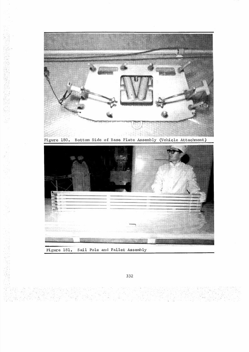
8/8/2019 MSFC Skylab Crew Systems Mission Evaluation
http://slidepdf.com/reader/full/msfc-skylab-crew-systems-mission-evaluation 356/397
Figure 180. Bottom Side of Base Plate Assembly (Vehicle Attachment)
_i:i=i:i:ii_i:i'i_i_i:iiiiiiii
:4
M:i:ili:!!zi
332
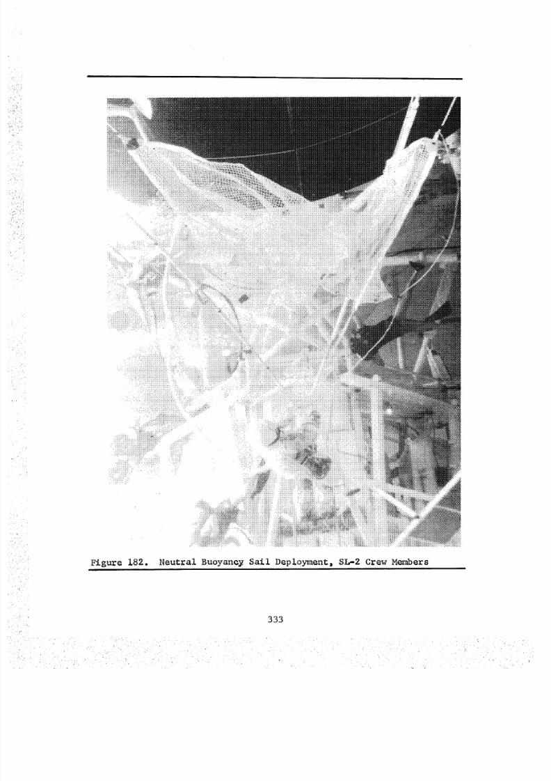
8/8/2019 MSFC Skylab Crew Systems Mission Evaluation
http://slidepdf.com/reader/full/msfc-skylab-crew-systems-mission-evaluation 357/397
:::+::::::
:::::::::i:!$i
Figure 182. Neut=al Buoyan=y Sail Depl0yment_ SL-2 Crew Memxbers
333

8/8/2019 MSFC Skylab Crew Systems Mission Evaluation
http://slidepdf.com/reader/full/msfc-skylab-crew-systems-mission-evaluation 358/397
e. Foot Restraint and Adapter Assembly, IOM50445-I - The
foot restraint and adapter plate assembly consisted of the workshop
portable foot restraint, located on board, and an adapter plate made
of stainless steel (Figure 183).
This assembly was required in order for the EVA crewman's lower
body to be adequately restrained in the proper attitude in the
structure of the A-frame on the ATM (from which EV2 could deploy and
adjust the sail).
3. Crew Hardware Evaluation - Upon selection of the sail confi-
guration, the related hardware was designed and fabricated. The crew
participation during this time was extremely valuable and expedited the
time required for producing finished, workable hardware. The prime
and back-up crews participated in both one-g and neutral buoyancyevaluation of the finished hardware.
The neutral buoyancy testing program was conducted to evaluate
the sail's design and to provide simultaneous training of the flightcrew. The MSFC neutral buoyance simulator, with the full scale
Skylab mockup, was fitted with the sail hardware necessary for evalu-ation activities. The first neutral buoyancy evaluation of the thermal
sail concept was performed on May 18, 1973.
The sail material selected for neutral buoyancy simulation was
.5-in. nylon netting. This material was chosen to minimize the
dynamic drag incurred while moving the sail through the water.
Figure 182 depicts the neutral buoyancy operations in one of thesimulation runs.
On May 21, 1973, a one-g demonstration/evaluation, shown in
Figure 184, was conducted with prime and backup SL-2 crew members,
and engineering personnel. The purpose of this l-g demonstration was
to validate the sail configuration's method of deployment, and to
familiarize crew members with hardware and procedures.As a part of equipment qualifications, the crew conducted a Crew
Compartment Fit and Function (C2F 2) test prior to flight equipment
acceptance.
Figure 185 illustrates the C2F 2 activities upon completion of MSFCthermal sail design and development.
4. Twin Pole Sail Deployment - Deployment of the twin pole sail
was accomplished by two crewmen, EV-I and EV-2. After loading all
the equipment in the Airlock Module (AM), EV-I ingressed the VF foot
restraints. EV-2 then passed out the following equipment which was
stowed in the FAS area: the two Sail Pole Stowage Plates, the Sail
Bag, the Base Plate, the two Clothesline Assemblies, and the FootRestraint.
EV-2 egressed the AM and translated to the double handrail near
the outrigger on the ATM. The Foot Restraint was passed to EV-2 on
the A_i Film Transfer Boom and locked in place on the outrigger
structure. After EV-2 was in position in the Foot Restraint, the SailPole Base Plate was passed out on the boom and was also installed on
the outrigger. The Sail packaged in the sailbag was then transferred
in the same manner and tethered to the Base Plate.
334
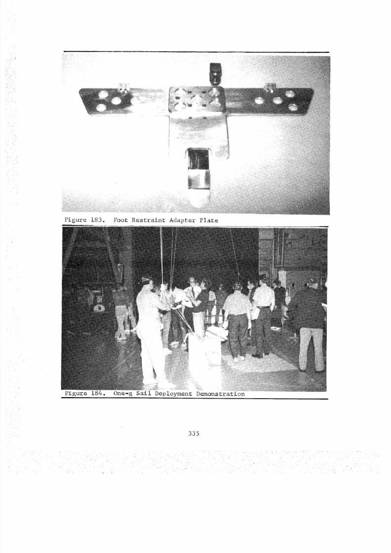
8/8/2019 MSFC Skylab Crew Systems Mission Evaluation
http://slidepdf.com/reader/full/msfc-skylab-crew-systems-mission-evaluation 359/397
Figure 183. Foot Restraint Adapter Plate
Figure 184. One-g Sail Deployment Demonstration
335
q
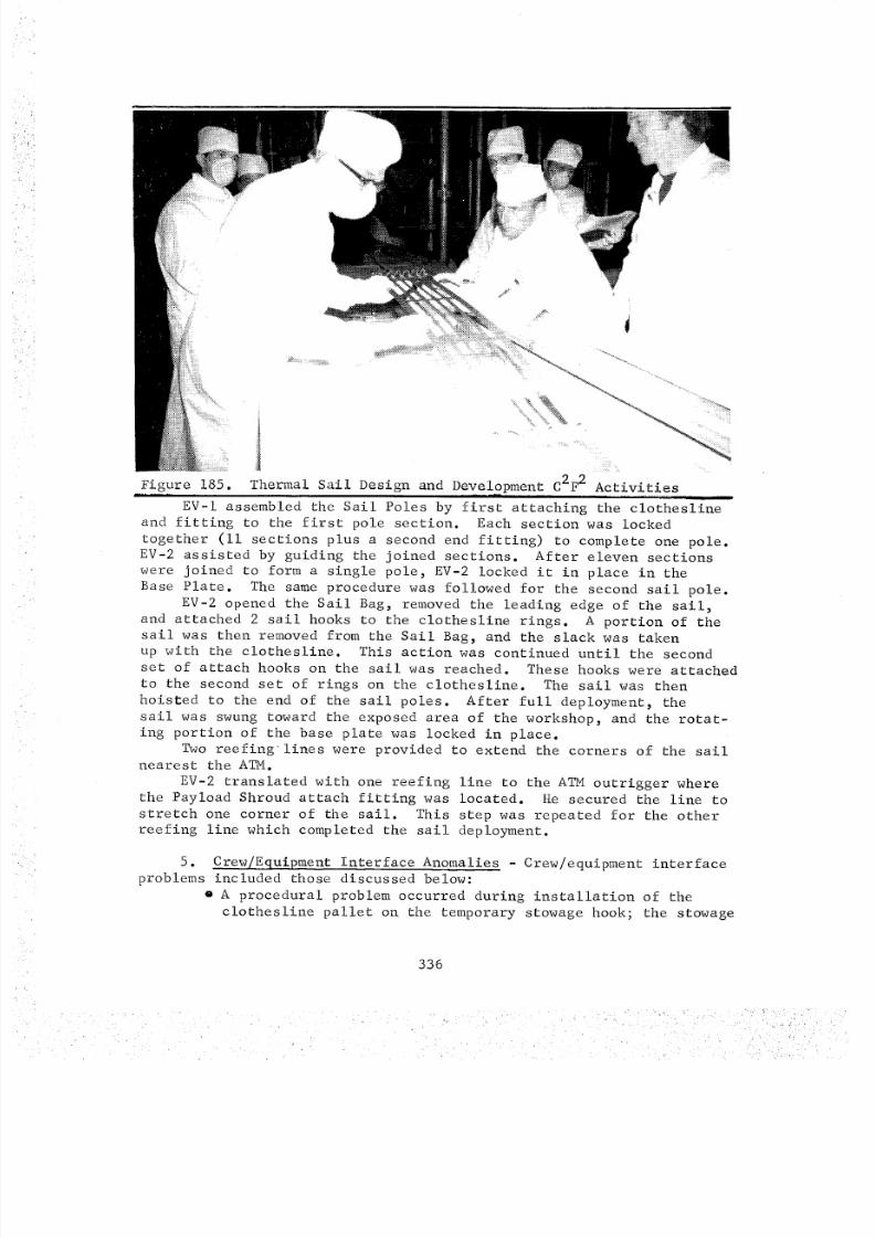
8/8/2019 MSFC Skylab Crew Systems Mission Evaluation
http://slidepdf.com/reader/full/msfc-skylab-crew-systems-mission-evaluation 360/397
, _
Figure 185. Thermal Sail Design and Development C2F 2 Activities
EV-I assembled the Sail Poles by first attaching the clotheslineand fitting to the first pole section. Each section was locked
together (ii sections plus a second end fitting) to complete one pole.EV-2 assisted by guiding the joined sections. After eleven sections
were joined to form a single pole, EV-2 locked it in place in the
Base Plate. The same procedure was followed for the second sail pole.
EV-2 opened the Sail Bag, removed the leading edge of the sail,and attached 2 sail hooks to the clothesline rings. A portion of the
sail was then removed from the Sail Bag, and the slack was takenup with the clothesline. This action was continued until the second
set of attach hooks on the sail was reached. These hooks were attached
to the second set of rings on the clothesline. The sail was then
hoisted to the end of the sail poles. After full deployment, the
sail was swung toward the exposed area of the workshop, and the rotat-
ing portion of the base plate was locked in place.Two reefing lines were provided to extend the corners of the sail
nearest the ATM.
EV-2 translated with one reefing line to the ATM outrigger wherethe Payload Shroud attach fitting was located. He secured the line to
stretch one corner of the sail. This step was repeated for the otherreefing line which completed the sail deployment.
5. Crew/Equipment Interface Anomalies - Crew/equipment interface
problems included those discussed below:
o A procedural problem occurred during installation of the
clothesline pallet on the temporary stowage hook; the stowage
336
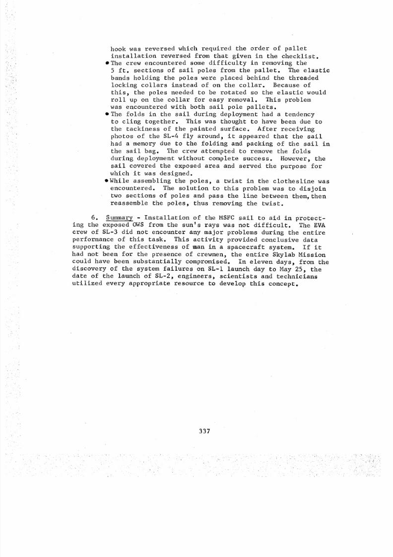
8/8/2019 MSFC Skylab Crew Systems Mission Evaluation
http://slidepdf.com/reader/full/msfc-skylab-crew-systems-mission-evaluation 361/397
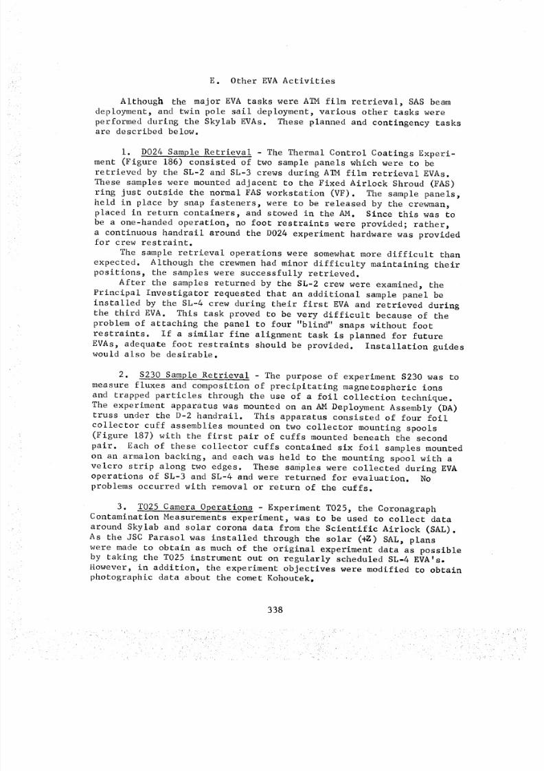
8/8/2019 MSFC Skylab Crew Systems Mission Evaluation
http://slidepdf.com/reader/full/msfc-skylab-crew-systems-mission-evaluation 362/397
E. Other EVAActivities
Although the major EVAtasks were ATMfilm retrieval, SASbeamdeployment, and twin pole sail deployment, various other tasks were
performed during the Skylab EVAs. These planned and contingency tasksare described below.
i. D024 Sample Retrieval - The Thermal Control Coatings Experi-
ment (Figure 186) consisted of two sample panels which were to be
retrieved by the SL-2 and SL-3 crews during ATM film retrieval EVAs.
These samples were mounted adjacent to the Fixed Airlock Shroud (FAS)
ring just outside the normal FAS workstation (VF). The sample panels,
held in place by snap fasteners, were to be released by the crewman,placed in return containers, and stowed in the AM. Since this was to
be a one-handed operation, no foot restraints were provided; rather,
a continuous handrail around the D024 experiment hardware was providedfor crew restraint.
The sample retrieval operations were somewhat more difficult thanexpected. Although the crewmen had minor difficulty maintaining their
positions, the samples were successfully retrieved.
After the samples returned by the SL-2 crew were examined, the
Principal Investigator requested that an additional sample panel be
installed by the SL-4 crew during their first EVA and retrieved during
the third EVA. This task proved to be very difficult because of the
problem of attaching the panel to four "blind" snaps without foot
restraints. If a similar fine alignment task is planned for future
EVAs, adequate foot restraints should be provided. Installation guideswould also be desirable.
2. $230 Sample Retrieval - The purpose of experiment $230 was to
measure fluxes and composition of precipitating magnetospheric ions
and trapped particles through the use of a foil collection technique.
The experiment apparatus was mounted on an AM Deployment Assembly (DA)truss under the D-2 handrail. This apparatus consisted of four foil
collector cuff assemblies mounted on two collector mounting spools
(Figure 187) with the first pair of cuffs mounted beneath the second
pair. Each of these collector cuffs contained six foil samples mounted
on an armalon backing, and each was held to the mounting spool with a
velcro strip along two edges. These samples were collected during EVA
operations of SL-3 and SL-4 and were returned for evaluation. Noproblems occurred with removal or return of the cuffs.
3. T025 Camera Operations - Experiment T025, the CoronagraphContamination Measurements experiment, was to be used to collect data
around Skylab and solar corona data from the Scientific Airlock (SAL).
As the JSC Parasol was installed through the solar (+g) SAL, plans
were made to obtain as much of the original experiment data as possibleby taking the T025 instrument out on regularly scheduled SL-4 EVA's°
However, in addition, the experiment objectives were modified to obtainphotographic data about the comet Kohoutek°
338
8/8/2019 MSFC Skylab Crew Systems Mission Evaluation
http://slidepdf.com/reader/full/msfc-skylab-crew-systems-mission-evaluation 363/397
m iL
SAMPLE RETURNCONTAINER(1)) . ,. _ .-i:_o_:'_,'," .":" / ' i
i ! ":_ X::/i ! i i iSAMPLE i_ ' ",_ o.,::." !RZTURN ! i ", ..'::': i iCONTAINERS i ! ", ..'::" i ,,"
\ il::...... .......'i
M£TAL SNAP / i." _'_'_'_-\. "-- '-_._- . "'_-:: /'"_"_'_,_':: '"
FASTENERS i !:_:.:"_ >, • _ :! _ "_'," _g,', .
CONTROL _ _...... "."__'_--_'_Z"._-_.':*_COATING_V "_*'"_'i ,_ -_ _ i: _'_-'_._'_-""POLYMERICFI LM%_- _ _',':_"_'_'*_-_:_-B_!_i _ _'_.'_ .."STRIP PANELS '_'..,..._:::'" /_')i )! !p,.o-"',:":_..-"
pip PIN AND "_ ".--.. ..........LANYARD
THERMAL CONTROL COATING POLYMERIC FILM STRIPTRAY(2 PANELS) TRAY (2 PANELS) /
TO SU_
Figure 186. D024 Experiment
FOIL COLLECTORCUFF ASSEMgLIES (2)
02 HANORAI
FOIL STRIPS(6 PLACES)
'CALIBRAT IO,_SHIELDS
FOIL STRIPS(6 _LACES)
COLLECTOR MOUNTINGSPOOLSz)
Figure 187,i ,
FOIL COLLECTOR INSTALLED
(AIM DEPLOYMENT ASSEMBLY)
$230 Experiment:
339
8/8/2019 MSFC Skylab Crew Systems Mission Evaluation
http://slidepdf.com/reader/full/msfc-skylab-crew-systems-mission-evaluation 364/397
The experiment apparatus consisted of a newly designed and built
adjustable EVA bracket, the coronagraph canister and camera, and an
occulting disc mounted on a boom (Figure 188). The EVA bracket was to
be mounted on a DA truss near the D-I handrail at the Fixed Airlock
Shroud workstation (VF).
Fbr the first EVA of SL-4, the T025 apparatus was mounted at the
VF. During camera operation, the shutter speed control knob became
loose. Only five photographs out of a planned 40 were obtained.
Instead of trying to repair the camera during EVA, the picture
taking sequence was stopped, and the equipment was returned (after
removal of the thermal blanket cover) to the AM. There, following theEVA, the T025 hardware underwent troubleshooting, and the crew success-
fully repaired the shutter speed knob. The T025 hardware was used
during subsequent EVAs to obtain ultraviolet and visible photographs
of Kohoutek. Throughout the remaining three EVAs, no problems occurred
with operation of the camera or EVA bracket, and subsequent T025
experiment performance was without incident.
4. $201 Camera Operations - Experiment $201, XUV Electronographic
Camera, was developed to collect extreme ultraviolet (XUV) photographicdata on Comet Kohoutek. Investigations of the comet's halo were to
be made in the hydrogen lyman a line, and the XUV lines of oxygen andcarbon monoxide. The experiment consisted of a canister enclosed
camera, a film transport box, and an adjustable EVA bracket that attached
to an AM Deployment Assembly truss at the same point that T025 was
installed near the Fixed Airlock Shroud workstation (VF).
Pointing the camera during EVA was to be accomplished by sighting
through two frame finder circles on the wide side of the canister.
The two circles were designed to fold down between the canister ribs
behind the handles on the canister side. When released by a latch,
the two circles were to spring up perpendicular to the canister side,
the larger ring forward of the smaller one. With his eye about sixinches behind the center of the rear ring, the crewman could see both
rings merge to outline the full 20 degrees field of view of the camera.
Two toggle switches were provided for activating main power and
initiating a 205 second sequence of eight exposures. Two status lights
were also provided to indicate a sequence in progress (green light) and
a film advance in progress (white light).
$201 EVA operations were performed during the SL-4 second, third
and fourth EVAs. Prior to EVA operation the crew noticed that the green
"sequence in progress" light was actually reddish-brown, and the light
intensity was low, but this caused no problem during EVA operations.
No problems were encountered during experiment mounting or operation.
5. S020 Solar Photography - Experiment S020, UV X-Ray Solar
Photography, was scheduled to be performed on SL-3 and SL-4 through the
solar Scientific Airlock (SAL) to photograph X-ray and extreme ultra-
violet spectra of the sun in wavelength regions from i0 to 200 _ .
Due to the JSC Parasol occupying the (+z) SAL, the S020 experiment,
340
8/8/2019 MSFC Skylab Crew Systems Mission Evaluation
http://slidepdf.com/reader/full/msfc-skylab-crew-systems-mission-evaluation 365/397
T025 EVA BRACKET
DA STRUTCORONAGRAPH INSTRUMENTS
Figure 188. T025 EVA Configuration
along with the preceding $201 and T025 experiments, was mounted on the
DA truss on the opposite side of the truss from the other two experi-ments. A special EVA bracket was designed and installed on the S020
equipment. S020 was successfully performed on three SL-4 EVAs withexposures up to one hour being obtained.
During deployment of S020, the crew experienced slight difficulty
in attaching the mount to the DA truss. The mount twisted during thetightening operation. In addition, the ball joint on the mount was
difficult to adjust, and the crew felt a larger ball could have madeadjustments easier.
The SL-4 crew reported a number of pinholes in each of the two
filters during preparation for the final EVA. It was felt, however,
that the size of the holes as described would not allow enough lightthrough to cause any problems.
6. S149 Deployment - The purpose of the S149 Particle Collection
experiment was to determine the mass distribution of micrometeorites
in near-earth space by a study of impact phenomena on prepared surfaces.
The experiment apparatus consisted of a motor drive/cassette support
unit, detector cassettes and an EVA adapter bracket (Figures 189 and
190). This bracket provided a method for mounting and positioning
the experiment on the rim of the A_I_ solar shield (Figure 191) using
a two jaw mechanism (one fixed, one movable) which was activated by
a clamp locking handle. This EVA bracket was developed after the JSC
Parasol was installed in the Scientific Airlock (SAL) window, thereby
precluding nominal S149 operations through the SAL. The experiment
apparatus also contained a crank handle for manually deploying thefour cassette arms.
341
8/8/2019 MSFC Skylab Crew Systems Mission Evaluation
http://slidepdf.com/reader/full/msfc-skylab-crew-systems-mission-evaluation 366/397

8/8/2019 MSFC Skylab Crew Systems Mission Evaluation
http://slidepdf.com/reader/full/msfc-skylab-crew-systems-mission-evaluation 367/397
$149 EVA ADAPTER BRACKET
(BOTTOM VIEW) (SEE FIGURE
1-1a FOR ADAPTER BRACKET
E]CI'ENS ION. ).
_- '........... -S149 DETECTOR ASSEMBLY%
• . .__ i k IN ALTERNATE EVA ATM• CONFIGURATION
%
(VEHICLE BODY AXIS) %,,
%
%-z +Y (VZ_CLE _OD_AXlS)
Figure 191. S149 Mounting Configuration
During EVA operations the S149 operated as planned with no major
problems. The EVA bracket and cassette deployment mechanism operatedsatisfactorily.
7. ATM Door Ramp Latch Removal - On several occasions prior to
the SL-3 first EVA, the aperture door failed to open when commanded
during operation of the S055 experiment. This problem was overcomeby simultaneously commanding both windings of the redundantly wound
motor amature to open the door. It was suspected that the problem
was the result of the door ramp latch lubricant's being worn off by
normal cycling of the door. Since the ramp latch was needed only for
supporting the door during launch and served no useful function after-
wards, a proposal was made to have a crewman remove the latch duringthe next EVA.
The Mission Support Mockup (MSFC Bldg. 4619) and the ATM back-up
unit were examined to determine what would be required to remove thelatch. It was found that the latch was mounted to the ATM canister
with two hex-head screws which could be removed with an on-board
combination wrench. Although one screw was accessible to a socket/
ratchet tool, the other bolt was shrouded and could be removed only
with a 7/16 in. open-end wrench. Consequently, it was decided that
the on-board 7/16 in. combination wrench should be used to remove
both screws. The wrench was modified for use with the EVA glove usingon-board materials (tape, etc) to increase the handle diameter. The
ramp latch had been installed with three adjustment shims between the
343
8/8/2019 MSFC Skylab Crew Systems Mission Evaluation
http://slidepdf.com/reader/full/msfc-skylab-crew-systems-mission-evaluation 368/397
latch and the canister. These shims, along with the latch, two screws,and two lockwashers, were to be retrieved to prevent them from float-ing into the ATMcanister or distracting the star tracker; on-boardtape was selected to affix the various parts to the ATMSun End (VS)film tree for return to the Airlock Module.
Another question arose with regard to the position of the S055ramp latch relative to the crewmanin the Sun End workstation (VS)foot restraints. With the experiment canister in position for S082Aand B film replacement, the crewmancould not reach the S055 ramp latch.The ATMmission support mockupwas used to determine the roll angle(in this case, +3000 arc min) on the ATMControl and Display Panel(Counter No. i) which would position the ramp latch optimally for thecrewman.
During the first EVA, after nominal film retrieval operation atthe SunEnd, the experiment canister was rolled to +3000 arc min forremoval of the S055 ramp latch. The door was cycled open and closedseveral times, and a slight, jerky motion was noticed as the doorengaged and disengaged the ramp latch. The bolts, washers, ramp
latch, and two shims were then retrieved and mounted under the tape onthe VS tree. One shim escaped in a direction awayfrom the canistersurface. The other ramp latch gear was successfully returned to theAirlock Module taped to the Sun End film tree.
The latch was returned with the crew for optical testing of theS-13G paint. Except for the difficulty of gathering eight smallpieces of gear simultaneously, no problems occurred. After removalof the ramp latch, the door was cycled open and closed. No binding orjerking motions were observed.
Later, during the SL-3 Mission, the S056 and S082Adoors beganto malfunction, exhibiting the samesymptomsas the S055 door hadearlier. Because of that similarity, and because of the disappearanceof the sticking problem with the S055 door after latch removal, itwas decided to remove the ramp latches on the S056 and S082Adoors.As the latches, bolts, and shims were identical to those on S055, theonly change in the removal procedure was the recommendedoll positionof the experiment canister. The ATMMission Support Mockupwas againused to determine the best canister roll angles. These were found tobe +3000 for S056and -7200 for S082A. The procedures sent to thecrew were identical to the procedures sent for S055 latch removal.
During the third EVA, after nominal Sun End film retrieval tasks,the experiment canister was rolled to +3000 arc min for S056ramp latchremoval. The door was cycled open and closed for crew observation.A jerky motion was noticed during opening and closing. Removalwasperformed with no difficulty. Nevertheless, as the ramp latch gear was
being taped to the Sun End film tree, all four shims and one screwdeparted into their own near-Skylab trajectories.The canister was then positioned for removal of the 8082Aramp
latch. The door was cycled open and closed. The samejerky motionnoticed on S056was also observed during S082Adoor movement. Duringremoval of the first latch screw, the crewmanremovedone foot fromthe foot restraint to extend his reach envelope. During removal of thesecond screw, the crewmanremovedboth feet. All latch gear was retrievedand taped to the VS tree.
344
8/8/2019 MSFC Skylab Crew Systems Mission Evaluation
http://slidepdf.com/reader/full/msfc-skylab-crew-systems-mission-evaluation 369/397
The major problem associated with the removal of the ramp latcheswas the collection and stowage of the shims, bolts, washers, and latchesafter their removal. The use of tape to restrain these pieces (8 perlatch) was not totally successful; four shims and two bolts were lost.Potentially, each of these hardware pieces, unrestrained, could have
interfered with star tracker operation, ATMobservations, etc. Adependable stowage method should be developed for use in future EVoperations in instances where small hardware must be removedand re-trieved.
8. S052 - Disc Cleaning - During operation of the S052 experi-
ment on SL-2, optical glare was observed on one of the occulting discs.
It was postulated that this glare was caused by a small (imm dia.)
piece of contamination on the outermost external occulting disc (DI).If this were true, it was felt that a crewman could remove the debris
with an onboard brush and return the S052 experiment to its originalcondition.
It appeared from a review of the Mission Support Mockup in Bldg.
4619 and the flight back-up unit in Bldg. 4708 that a crewman could
easily reach the DI disc and would have adequate visibility to identify
the contamination and remove it. The disc, however, had a sharp out-
side edge, so the crewman would have to be careful not to cut his
glove. An adequate lens cleaning brush was identified from stowagecontainer F524, and a cleaning stroke of center-to-outside was recom-
mended to prevent cutting the brush bristles on the disc.
The position of the ATM canister for normal VS operations was not
adequate, however, because the crewman could not reach S052 from the
VS foot restraints. Therefore, the Crew Systems ATMMission SupportMockup was used to determine the best position of the canister for the
S052 cleaning operation. Disc inspection and cleaning procedures,including a canister position of +6600 arc sec, were transmitted to thecrew for use during the second EVA.
During that EVA, the ATM experiment canister was rolled to the
recommended required roll angle with the door open. Crewman EV2
located the contamination and removed it with the optics cleaning kitbrush. The S052 aperture door was then closed.
During SL-3, contamination was again noticed on the occulting
disc. The disc cleaning procedures used during SL-2 were again sent
to the crew for use during the third EVA, and the contamination was
removed with no problems. The lens cleaning brush was judged to beadequate for the task.
9. ATM Contingency Door Opening (S054_ S082A_ - During SL-2, the
crew had difficulty opening the S054 aperture door. The door was
first commanded open unsuccessfully with the S054 "DOOR OPEN" switch on
the ATM Control and Display Panel, and then through the ATM Digital
Address System (DAS). When these commands failed to open the door,
the DAS was used to activate, simultaneously, both circuits of the
aperture door drive motor's redundantly wound armature. This action
appeared successful--the S054 door talkback indicated that the door
had opened. The door was left open in case it could not be opened again.
345
k f?
8/8/2019 MSFC Skylab Crew Systems Mission Evaluation
http://slidepdf.com/reader/full/msfc-skylab-crew-systems-mission-evaluation 370/397
8/8/2019 MSFC Skylab Crew Systems Mission Evaluation
http://slidepdf.com/reader/full/msfc-skylab-crew-systems-mission-evaluation 371/397
ii. Rate Gyro Package Cable Installation - In the early part
of the SL-2 mission, the orbital attitude rate gyros had begun to give
faulty and sometimes erratic indications. To correct this problem,
an extra set of gyros was assembled into a Rate Gyro Package (RGP)"Six Pac_' and was flown aboard SL-3. The "Six Pack" was to be
mounted in the Multiple Docking Adapter (MDA). To integrate these rategyros into the cluster attitude control system, however, a new cable
would have to be installed between an ATM trunnion plate and the ATM
Workshop Computer Interface Unit (WCIU). A set of procedures was
provided in the Saturn Workshop (SWS) Cue Cards. Special connectorswith extended backshells that enabled the EVA crewman to mate the
connectors by hand were used on the RGP cable. A set of connector
pliers was also developed for use in disconnecting the old RGP cable.
These pliers were similar to standard connector pliers, but had a
tether ring and a handle orientation compatible with the EVA gloves.
The RGP cable was installed during the SL-3 second EVA. The
installation required that the Skylab attitude control system be
disabled from the time the connections were broken at the ATM trunnion
until after the connections were complete. Because the area
around the WCIU and the Deployment Assembly trunnion area were not
illuminated by EVA lights, the crew inspected both areas during the
first dayside pass to verify crew restraint methods, connector acces-
sibility, and the cable routing scheme. The connector pliers were
fitted to the connectors and found to be the proper size. The adjacentwire bundles were then inspected and found to allow sufficient clear-
ance for removing the connectors. Body restraint was also determined
to be satisfactory at both locations. The cable routing scheme was
discussed among the crewmen and was not considered to be a problem.
Other EVA activities were subsequently performed during the orbitalnight and are discussed in the sections below.
Prior to the next sunrise, the cable connection was made at thetrunnion, the cable was routed to the ATM WCIU area, and EV2 restrained
himself at the WCIU for the cable installation operations. Immediatelyafter sunrise, he began breaking and making the connections at the
WCIU and trunnion while EV3 read the installation procedures. Less than
four minutes later, all connections had been made. No problems were
encountered with use of the tool, connector backshells, crew restraint,or positioning of the connectors.
12. Sail Sample Installation Retrieval - After the JSC parasolwas deployed on SL-2, a study was performed to determine the effect of
solar radiation on the parasol material. It was discovered that there
might be some material degradation with extended exposure. As a
result of this study, the SL-2 crew was requested to cut an 18 inch
square section from the Stand-Up EVA (SEVA) sail (made from the same
type of material as the parasol except with a layer of Kapton) and
mount it to an ATM Deployment Assembly (DA) truss. The proceduretransmitted to the crew was to sew velcro along two sides of the
parasol sample prior to EVA. The sample was then to be wrapped around
a tubular truss near the Fixed Airlock Shroud Workstation (VF) where itwould be exposed to direct sunlight.
347
8/8/2019 MSFC Skylab Crew Systems Mission Evaluation
http://slidepdf.com/reader/full/msfc-skylab-crew-systems-mission-evaluation 372/397
During the second EVAof SL-2, EV2 installed the JSC sail sampleto a truss near the ATMdeployment motor. As no foot restraints wereavailable, and as wrapping a flimsy article around a truss is essenti-ally a two-hand task, crew stability was severely limited. But, withEVI holding EV2's feet, the sample was eventually deployed. If suchtasks are required during future EVAs, adequate restraints should beprovided.
During the third EVAof SL-3, the sample was retrieved. No prob-lems occurred.
In order to obtain more data on the effects of the space environ-ment on the JSCparasol material, two additional material sampleswerecarried aboard SL-3. Thesewere attached to old crew procedures CueCards, and the CueCards were mountedon a clipboard attached to auniversal mount. This mount could be attached to an EVAhandrail andadjusted to expose the material samples to direct sunlight.
During the EVA, EV2attached the universal mount to the S-IO hand-rail while his feet were held by EVl. Except for the lack of adequaterestraint, no problems occurred.
The samples were retrieved during the third SL-4 EVAwithoutdifficulty.
13. S193 Antenna Repair - The purpose of experiment S193,
Microwave Radiometer/Scatterometer Altimeter was to investigate active
and passive microwave sensing systems from an orbital altitude. The
experiment included a mechanically driven parabolic reflector (Figure192) that scanned in several programmed modes.
During SL-3 the antenna began to malfunction and would not scan
properly. To correct this problem, hardware and procedures were
developed to enable two EVA crewmen to check out and repair the antenna
or its associated electronics package. Several major problems had to
be solved: (I) the S193 antenna was on the side of Skylab where
nominal EVA operations were not performed and no EVA lights, handrails,
or foot restraints were available near the antenna, (2) the antenna
was large (44.5 in. x 21.2 in.) and massive (294 ibs), (3) the elec-
tronics were located beneath the antenna and would not be very acces-
sible to the crewmen, and (4) attempts to diagnose the problem from the
ground were only partially successful.
It was determined that crew translation to the S193 antenna from
the EVA hatch could be accomplished by using the mole sieve vent duct
along the exterior of the Multiple Docking Adaptor (MDA). The major
problem, however, was restraint of the crewmen at the antenna; develop-ment was begun on a "universal" foot restraint that would attach to a
variety of external hardware, including the trusses around the S193
antenna. After several iterations, a design was evolved which wouldsecure the OWS portable foot restraint to round trusses from i to 6 in.
in diameter, to the Fixed Airlock Shroud (FAS) ring, to the solar panel
back-up structure, and to various other external points which included
adjustments in roll and pitch to position the crewman at the worksite.
348
8/8/2019 MSFC Skylab Crew Systems Mission Evaluation
http://slidepdf.com/reader/full/msfc-skylab-crew-systems-mission-evaluation 373/397
//
Figure 192. S193 Antenna
S-193 M ICROWAVE R ADIOME TER_-- $CATE EROMET ER/ALT IMETER
Two sets of foot restraints were developed for experiment S193--one at MSFC and one at JSC. The JSC set was selected for use. This
foot restraint was not universal, but was designed to fit into a
lightening hole on the discone antenna launch tray near the S193
antenna. The JSC foot restraint was lighter than the MSFC concept, andwas therefore selected to be carried aboard SL-4 for the antenna
repairs.An antenna inspection/repair procedure fashioned after the Orbital
Workshop malfunction procedures was developed (Figure 193). Additional
crew instructions on separate pages were provided for each block of
the flow diagram. The tools and electronic equipment necessary to
repair the antenna were identified and packaged into a tool caddy.
These tools consisted of vice grips, hammer, screwdriver, allen bit,
ratchet and connector pliers.
Neutral buoyancy tests verified that the antenna repair taskscould be performed, but, because of the antenna's mass and size and
the inaccessibility of the electronic components, the task would be
both difficult and long.
During the first EVA of SL-4, two crewmen performed the inspection/repair tasks. EV2 translated to the S193 antenna and installed the
foot restraint. EVl then translated to the antenna, ingressed the
foot restraint and mounted the tool caddy on a deployment assembly
truss. EV2 began the inspection/repair task with EVl holding EV2's
feet for stability and passing tools as they were needed. During the
task, the two crewmen pinned the antenna's pitch gimbal and installed a
disable plug and jumper box. This locked the antenna in a fixed pitch
position and permitted operation of the antenna in a roll-scan only mode.
No major problems were encountered.
349
8/8/2019 MSFC Skylab Crew Systems Mission Evaluation
http://slidepdf.com/reader/full/msfc-skylab-crew-systems-mission-evaluation 374/397
Sl_ ROAD MAP|ZI[ |l
, 413 _ (,.z.,) I,+,.<,.,+, ,+,+, i ..... I i p 0"+°| Octet,ores ,t ue I (I.Z+i} I _ , i , . • !I IsZ4) I ' I,O I ,,Sm.L ,MPtt OF I IT+S l+
I-' , ,S_+m _O, r---'*'l <A.z-, I I I vm---._--.---s. I? ,_u i ? I P II II I
I ,,,,,,+°,- I , I-I,:'+.+,0M II I11.I-5} (l Z-lO) I I + AI,S FU_TXOI_L I I +" mOLL+ -- •
I |I J J I C.[C, (i Z-A) I I L" ' _'E$ -- I I
, " I ms mw,mtmtv[ _ t !
I+U I +_.J | | ' t'? r" PITCHOt I I-+ RoLLPot IZ AXIS Fu_:T,ON_. 13I_+, ,,.,-,, I ,,._°,-- I _ I I ,SSHO.mO / ,ss.o._D I
Is., ..,.+ 0.,, ,0 _ t,.+-,,) I IPROBLEmWAS I ! L It+_+"+" ,+'+ I , ' I ,AOCO++mCTIOm + + .• .. + ,,o, " t ., • , I l.m , I _,,, _ ,,,,_, i 'I POIWASHOeIEO I _+.+-m I 'l.m I I `'+ I I ..II | L-..--. .J I Z AxIS pteom.._ l I I-- " I TtSt (*,z.s) I | l ....
l | I | | +c_., I _ I ,NSTALL OISAIILt I 'LUOl l ,NSFN.L OITJUl+. [_tJ_ I
l'-+',,,s,,,o,,_<+ I I"?,, , ,, L,.,+o, I _++' 'm I I I'++'m l[Tts, (,.+-*_ l | hm.®to+, -- I " II C,_I mT+P._ OX,Vi _ l,Sl I | I .
l mete,+ j._ L_. t'-" m_c+..eamm'o,s I lzol , l'z+l " ''KS ,F 5 ,A,LS S[_ (tl,Z-S)++++t ,,,, _,0, / I I%+.,,., I r::;i+,.,s,,s, I
TTTi " -- • l..'-'" I._ l"""" I.+LJ i _ i ,s_ ,.,,s_mo,_ I ,s ,.to.,,+m 0oo,-+-C_3
-- " -- -- " T s[ CL_IUIU_ {i.Jt -IS) V_5 [
Figure 193. S193 General Repair Procedures
14. Skylab Vehicle Exterior Inspection - Prior to the firstSL-3 EVA, several anomalies occurred on one bus of the ATM electrical
power system. In order to determine whether a short circuit had
developed in the electrical power distributor, the crew was asked to
inspect the Power Transfer Distributor, which is 90 degrees to theright of the AEM Center Workstation. Scorched posts near the fuse
modules and gray residue near the vent ports would be convincingevidence of such a short circuit.
As part of a troubleshooting exercise to locate a coolant leak,
the crew was requested to examine the Multiple Docking Adapter (MDA)
exterior to identify any signs of leaks. The crew was advised oflocations to check and was told what types of deposits and discolora-
tions would be present if a leak had occurred.
These two inspections were performed during the SL-3 first EVA.
During inspection of the Power Transfer Distribution box, no residueor discoloration was observed around the gas ports, and the gas port
screens appeared clean. Also, no scorching was found around the fuse
module mounting screws.
The crewman (EV2) then described the exterior of the Command
Module (CM) and the MDA. The CM was a tan color where it was exposedto the sun with a darker brown color around the hatch. A dark tan
line was also observed extending from under the CM hatch to the docking
window. The MDA was examined for any discoloration or streaks which
would indicate a coolant leak. No evidence of a leak was observed.
350
8/8/2019 MSFC Skylab Crew Systems Mission Evaluation
http://slidepdf.com/reader/full/msfc-skylab-crew-systems-mission-evaluation 375/397
15. S054 Filter Wheel Positioning - During SL-4, the S054 filter
wheel jammed. Neither ground commands nor onboard commands from the
ATM Control Panel could move the wheel. Since telemetry indicated
that the wheel was jammed between two filters, film data would be
severely degraded until the wheel was positioned at one of the six
filters.An examination of the ATM back-up unit indicated that the filter
wheel could be turned manually be a crewman at the ATM Center Work-
station (VC) with a long blade screwdriver. However, several signifi-cant problems had to be solved.
eFirst, none of the SL-4 crewmen had ever seen the filter
wheel or the surrounding hardware, nor were there on-boardphotographs or drawings.
• Second, during the EVA, the crewman would not be able to
see the filter wheel without the aid of a mirror andadditional lighting.
eThird, the filter wheel could not be moved without destroy-ing the filters with the screwdriver.
The first problem was solved by giving the crew a detailed verbal
description of the filter wheel and the surrounding hardware. To
solve the visibility problem an onboard penlight was taped to the
extension mirror (Tool Kit No. i). This mirror/light could be held bythe crewman over the aperture to enable him to see the filter wheel.
The S054 experiment personnel determined that the wheel should be
positioned at the blank (no filter) position to avoid taking photo-graphs through a broken filter.
The procedure sent to the crew was to: (i) remove the exposed
S054 film magazine from the experiment canister receptacle at the VC,(2) place a new film magazine in the receptacle with a shutter over-
ride mechanism attached to the base (this latched the shutter open to
permit access to the filter wheel), (3) remove the new film magazine,and (4) insert the screwdriver through the shutter opening into the
filter wheel, while using the mirror and light to provide adequate
visibility. The crew was then to insert the screwdriver blade into a
filter and force the wheel to the right until another filter could be
seen on the left. This procedure was to be repeated until the blank
filter was positioned in the optical path.
During the second EVA, this task was performed. The used film
magazine was removed, and the new magazine with the shutter override
mechanism was installed, opening the shutter. The film magazine was
removed and, as the filter wheel was being turned, the shutter unexpect-
edly closed on the screwdriver blade. After repeated attempts to
reopen the shutter failed (due to distortion of the blades), and after
consultation with ground controllers, the blades were forced apart,
clear of the light path. EV2 then proceeded with the rotation of the
filter wheel until the blank position was centered. The film magazinewas then replaced.
Although this task was difficult and the crew had not been
trained, the repair operations were successfully performed.
351
8/8/2019 MSFC Skylab Crew Systems Mission Evaluation
http://slidepdf.com/reader/full/msfc-skylab-crew-systems-mission-evaluation 376/397
Vll. TESTDATA
This section contains test data on select hardware items forhistorical and informational purposes only.
A. Waste ManagementI. Waste Management Design and Development Reviews - The Pre-
liminary Design Review of the Waste Management Subsystem was presented
at MSFC August 27-28, 1969. The same methods for basic fecal collec-tion and processing, contingency fecal collection and processing, and
vomit collection and processing presented at the PDR existed in the
final design. There was one exception. Vomit was to be collected in
a separate bag. It was changed so that contingency fecal collectionand vomit collection utilized the same bag.
The urine collection and preservation system presented at the
PDR utilized a bag for each collection. Each bag, after collection,
was placed in the processor where the urine was vacuum dried, then
stored, and returned via the command module for analysis.Subsequent to the PDR, the preservation scheme for urine was
changed for vacuum drying to chilling during collection and sampling;
and freezing of the sample obtained after each 24-hour collection
period. The original system utilized a single collection bag. After
each collection, the gas in the bag was expelled through a zitex fil-
ter membrane, and the bag containing the urine was held against a
chill plate to maintain the urine below 59°F.
Just prior to the Critical Design Review in September 1970, a
failure of the original urine collection method occurred. The filter
in the collection bag clogged, and would not permit air flow after
being in contact with the urine for a period of time during chilling.
The Critical Design Review of the Waste Management Subsystem,
except for urine collection and preservation, was presented at MDAC
September 14-17, 1970. The same basic system was presented that was
presented at the PDR. The only significant difference was the utili-
zation of a 6 drawer processor instead of a nine drawer processor, due
to the elimination of vacuum drying urine.
At that time three methods of collecting urine were under design
and test: (i) a one-bag collection system which used a modified
collection bag with a larger filter which allowed holding the bag
open during the 24-hour collection period to limit filter exposure,(2) a two-bag collection system where the urine was collected in one
bag; then transferred to a holding bag that did not have a filter,
for chilling the urine, and (3) a centrifugal separator system that
separated the urine from the air and pumped the urine into a holding
bag for chilling the urine.The Critical Design Review of the Urine collection and preserva-
tion system was presented at Fairchild Industries March 31, April i,
1971. All three systems were presented at the CDR.
352
ii!iii li¸:! iii? ii!
8/8/2019 MSFC Skylab Crew Systems Mission Evaluation
http://slidepdf.com/reader/full/msfc-skylab-crew-systems-mission-evaluation 377/397
Subsequent to the CDR, the one- and two-bag schemes were cancel-
led and the separator system implemented.
At that time, the modifications to the urine system, to include
the separator, were as follows:
• Addition of a new 24-hour urine pool holding bag which
incorporated 2000 ML capacity, a recirculation line to
mix urine with the lithium chloride secondary volume
determination agent contained in the bag, a urine re-
ceiver capable of receiving urine and connecting to therecirculation line, and use of a screw on adaptor also
capable of cuff contingency mode collection.
• Urine Separators.
Folding teflon urine receiver and inlet hose and valve
assembly.• A rectractable pressure plate capable of exerting a
pressure equivalent to 6-inches of water on the urine
holding bag. It also would keep the bag in intimate
contact with the cold plate in order to chill the urine
pool. The pressure plate was actuated through the air-flow valve handle on the urine drawer front panel. This
plate connected mechanically to the volume measurement
indicator dial gage.• The drawers were modified to accommodate the urine sepa-
rators, urine collection bag, and pressure plate, etc.
• Additional equipment like hose rollers, UTCA adaptors,
new urine sample bags, etc.
During the SMEAT test conducted at JSC, Houston, during July
and August of 1972, it was determined that the 2000 ML capacity ofthe urine system was not adequate. As a result, the final design
parameters of the urine system were established during a meeting on
September 26, 1972 at JSC.The final iterations were as follows:
• Primary volume determination chemically using the lithiumchloride tracer.
• Elimination of recirculation by use of manually shaking
of the urine pool.
eDesign of a 4000 ML urine holding bag capable of alternate
cuff mode operation.
• Modification of the urine sample bag.
• Design of a urine bag container box and spring actuated
pressure plate.
eElimination of the mechanical dial gage volume measurement
system by a micrometer gage plate system used in conjunc-
tion with the urine bag box assembly and the manual
squeezer handle assembly used to take samples.
353
8/8/2019 MSFC Skylab Crew Systems Mission Evaluation
http://slidepdf.com/reader/full/msfc-skylab-crew-systems-mission-evaluation 378/397
• Design of a hard-metal cone-reciever in place of the oldteflon folded cone construction, and associated inlethose.
• Design of a combination urine sample bag holder andcrimper/cutter assembly for use in sampling and sealingthe sample.• Design of a urine bag box support mechanismcapable throughuse of sqeezer handles of applying additional pressure onthe urine collection bag to assure adequate filling of theurine sample bags. This device is also used in conjunctionwith the micrometer volumetric plate for mechanical volumemeasuring.
• Modification and simplification of the urine drawer toaccommodatehe newhardware.
• Design of newadapters for use with interface equipmentsuch as the UTCA'sand the urine dumpsystem.
There are no open action items from the Preliminary and CriticalDesign Reviews.
2. Subsystem Conclusions
a. Waste Processor
(i) Summary of Capabilities versus Design Require-
ments - The processor module had demonstrated its capability of
attaining the design requirements. The unit had:
(a) Demonstrated its ability to process feces,
diarrhea, and vomitus to an inactive state in which bacterial growth
was prevented.(b) Demonstrated that the leakage rate from the
cabin atmosphere through the processor was well within the 0.27 Ib/
day al lowance.(c) Demonstrated that it could be operated with
a minimum of crew time, effort, and maintenance.
(d) Successfully completed qualification unit
vibration testing (at MDAC).
(e) Met the touch temperature requirement of
105°F (except for indicator lamps).
(f) Successfully met the electrical requirements
such as over and undervoltage, input transients, and reversed polarity.
(2) Summary of Open Problems and Plans for Corrective
Action - There were no open problems or plans for corrective action
associated with the processor module. All problems generated during
the development and design phases were resolved satisfactorily.
354
8/8/2019 MSFC Skylab Crew Systems Mission Evaluation
http://slidepdf.com/reader/full/msfc-skylab-crew-systems-mission-evaluation 379/397
(3) Long Duration Operational Capability - The unitas a whole had been subjected to life testing of 140-cycles ofoperation of each of the six processing chambers to simulate onechamberoperation per day during a 28-day mission and two 56-day
missions. A cycle involved opening and closing the chamberdoor,vent valve, and locking handle; the pressure plate assembly anddamperwere also operated by virtue of their connection to thechamberdoor. Somefailures of indicator lamp filaments (eachlamp had two filaments) and timer skipping of i/2-hour incrementsoccurred. Voltage surges due to the test set-up were believedresponsible for lamp filament failures.
Timers were reworked to the production configuration, employ-ing aluminum rather than stainless gears for reduced inertia. Asecond 140-cycle operational life test was completed.
b. Collection Module
(i) Summaryof Capabilities Versus Design Require-ments - The Fecal/Urine Collection Module demonstrated its capabilityof attaining the design requirements. The unit:
testing.
coolant flows.
ments.
determination.
zero G environment.
(a) Successfully completed prototype vibration
(b) Beenable to supply the necessary airflow.(c) Been able to accommodatehe necessary
(d) Successfully met the electrical require-
(e) Attained the necessary accuracies for volume
(f) Demonstrated the ability to collect in a
(g) The capability for efficient maninterface.(h) The ability to prevent bacteria contamina-
tion in the airstream introduced by collection.
(2) Summaryof OpenProblems and Plans for CorrectiveActions - There were no open problems or plans for corrective actionassociated with the Fecal/Urine Collection Module. All problemsgenerated during the development and design phases were resolvedsatisfactorily.
(3) Long Duration Operational Capability - The unitas a whole was subjected to life testing and several of the morecritical componentssuccessfully underwent life tests in excessof the requirements. The more important componentsand theircapabilities were as follows:
355
8/8/2019 MSFC Skylab Crew Systems Mission Evaluation
http://slidepdf.com/reader/full/msfc-skylab-crew-systems-mission-evaluation 380/397
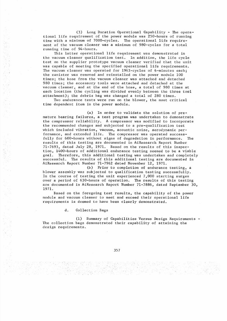
8/8/2019 MSFC Skylab Crew Systems Mission Evaluation
http://slidepdf.com/reader/full/msfc-skylab-crew-systems-mission-evaluation 381/397
(3) Long Duration Operational Capability - The opera-tional life requirement of the power module was 250-hours of runningtime with a minimumof 7000-cycles. The operational life require-ment of the vacuumcleaner was a minimumof 980-cycles for a totalrunning time of 94-hours.
This latter operational life requirement was demonstrated inthe vacuumcleaner qualification test. In addition, the life cycletest on the supplier prototype vacuumcleaner verified that the unitwas capable of meeting the specified operational life requirements.The vacuumcleaner was operated for 1963-cycles of 6-minutes each;the canister was removedand reinstalled on the power module i00times; the hose from the vacuumcleaner was attached and detached980 times; the accessory tools were attached and detached at thevacuumcleaner, and at the end of the hose, a total of 980 times ateach location (the cycling was divided evenly between the three toolattachment); the debris bag was changeda total of 280 times.
Twoendurance tests were run on the blower, the most critical
time dependent item in the power module.(a) In order to validate the solution of pre-
mature bearing failures, a test program was undertaken to demonstratethe compressor reliability. A compressor was modified to incorporatethe recommendedchanges and subjected to a pre-qualification testwhich included vibration, vacuum, acoustic noise, aerodynamic per-formance, and extended life. The compressor was operated success-fully for 600-hours without signs of degradation in performance. Theresults of this testing are documentedin AiResearch Report Number71-7693, dated July 28, 1971. Based on the results of this inspec-tion, 1400-hours of additional endurance testing seemedto be a viablegoal. Therefore, this additional testing was undertaken and completelysuccessful. The results of this additional testing are documented inAiResearch Report Number71-7962 dated November12, 1971.
(b) Prior to completion of endurance testing, ablower assembly was subjected to qualification testing successfully.In the course of testing the unit experienced 7,000 starting surgesover a period of 630-hours of operation. The results of this testingare documentedin AiResearch Report Number71-7886, dated September30,1971.
Based on the foregoing test results, the capability of the powermodule and vacuumcleaner to meet and exceed their operational liferequirements is deemedto have been clearly demonstrated.
d. Collection Bags(i) Summaryof Capabilities Versus Design Requirements -
The collection bags demonstrated their capability of attaining thedesign requirements.
357
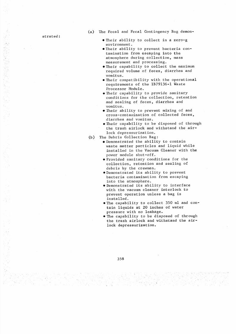
8/8/2019 MSFC Skylab Crew Systems Mission Evaluation
http://slidepdf.com/reader/full/msfc-skylab-crew-systems-mission-evaluation 382/397
strated:Ca)
(b)
The Fecal and Fecal Contingency Bag demon-
• Their ability to collect in a zero-genvironment.
• Their ability to prevent bacteria con-
tamination from escaping into theatmosphere during collection, mass
measurement and processing.
eTheir capability to collect the maximum
required volume of feces, diarrhea andvomitus.
• Their compatibility with the operational
requirements of the IB79136-I WasteProcessor Module.
• Their capability to provide sanitary
conditions for the collection, retention
and sealing of feces, diarrhea andvomitus.
• Their ability to prevent mixing of andcross-contamination of collected feces,
diarrhea and vomitus.
• Their capability to be disposed of throughthe trash airlock and withstand the air-
lock depressurization.
The Debris Collection Bag:
• Demonstrated the ability to contain
waste matter particles and liquid whileinstalled in the Vacuum Cleaner with the
power module shut-off.
• Provided sanitary conditions for the
collection, retention and sealing ofdebris by the crewman.
• Demonstrated its ability to prevent
bacteria contamination from escaping
into the atmosphere.• Demonstrated its ability to interface
with the vacuum cleaner interlock to
prevent operation unless a bag is
installed.
• The capability to collect 350 ml and con-
tain liquids at 20 inches of water
pressure with no leakage.
• The capability to be disposed of through
the trash airlock and withstand the air-
lock depressurization.
358
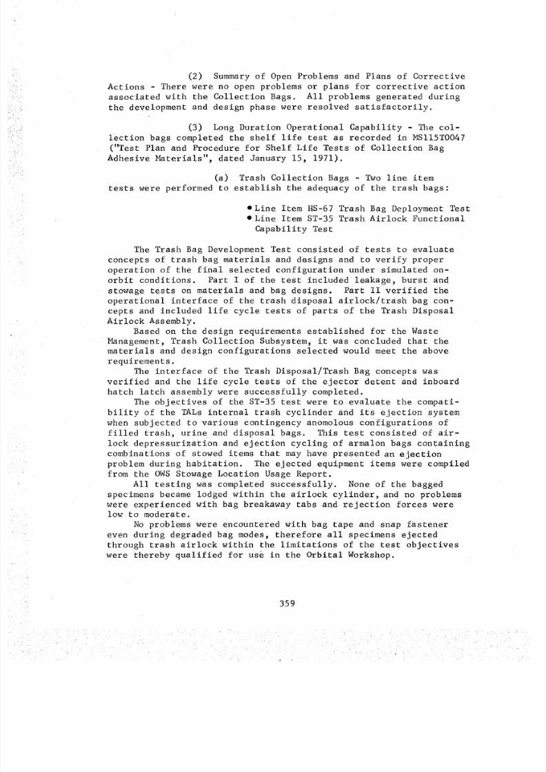
8/8/2019 MSFC Skylab Crew Systems Mission Evaluation
http://slidepdf.com/reader/full/msfc-skylab-crew-systems-mission-evaluation 383/397
(2) Summary of Open Problems and Plans of Corrective
Actions - There were no open problems or plans for corrective action
associated with the Collection Bags. All problems generated during
the development and design phase were resolved satisfactorily.
(3) Long Duration Operational Capability - The col-lection bags completed the shelf life test as recorded in MSII5T0047
("Test Plan and Procedure for Shelf Life Tests of Collection Bag
Adhesive Materials", dated January 15, 1971).
(a) Trash Collection Bags - Two line item
tests were performed to establish the adequacy of the trash bags:
• Line Item HS-67 Trash Bag Deployment Test• Line Item ST-35 Trash Airlock Functional
Capability Test
The Trash Bag Development Test consisted of tests to evaluate
concepts of trash bag materials and designs and to verify proper
operation of the final selected configuration under simulated on-
orbit conditions. Part I of the test included leakage, burst and
stowage tests on materials and bag designs. Part II verified the
operational interface of the trash disposal airlock/trash bag con-
cepts and included life cycle tests of parts of the Trash Disposal
Airlock Assembly.
Based on the design requirements established for the Waste
Management, Trash Collection Subsystem, it was concluded that the
materials and design configurations selected would meet the above
requirements.
The interface of the Trash Disposal/Trash Bag concepts was
verified and the life cycle tests of the ejector detent and inboardhatch latch assembly were successfully completed.
The objectives of the ST-35 test were to evaluate the compati-
bility of the TALs internal trash cyclinder and its ejection system
when subjected to various contingency anomolous configurations of
filled trash, urine and disposal bags. This test consisted of air-
lock depressurization and ejection cycling of armalon bags containing
combinations of stowed items that may have presented an ejection
problem during habitation. The ejected equipment items were compiled
from the OWS Stowage Location Usage Report.
All testing was completed successfully. None of the bagged
specimens became lodged within the airlock cylinder, and no problems
were experienced with bag breakaway tabs and rejection forces were
low to moderate.
No problems were encountered with bag tape and snap fastener
even during degraded bag modes, therefore all specimens ejected
through trash airlock within the limitations of the test objectives
were thereby qualified for use in the Orbital Workshop.
359
8/8/2019 MSFC Skylab Crew Systems Mission Evaluation
http://slidepdf.com/reader/full/msfc-skylab-crew-systems-mission-evaluation 384/397
e. Centrifugal Urine Separator
(i) Summaryof Capabilities Versus Design Require-ments - Based on the successful completion of all special feasibilitytesting, Design Verification Testing, and Production Acceptance Test-
ing of each unit, it was concluded that the CUSAwas compliant withall of the applicable SCDdesign requirements.
(2) OpenProblem and Resolution Summary- None
(3) Time/Life Cycle Limitations - The SV748753-ISupport and Filter was a time/life cycle limited component. Basedupon the Design Verification Testing and resultant data obtained,Hamilton Standard recommendedhe Support and Filter be replacedafter 28-days of use.
f. Trash Airlock
(i) Summaryof Capabilities Versus Requirements -Based on analytical results, it was determined that actual factorsof safety exceeded required factors of safety. Therefore, thestructural integrity of critical componentsof the trash disposalairlock wasverified analytically.
It was concluded from the analytical and test results that thetrash disposal airlock met all design requirements for use on theOWS.
The trash airlock development test (line item HS-24) wascom-pleted successfully and verified the design requirements for leakage,proof and burst pressures, vibration, and repeated functional cyclesUnder orbital differential pressure and temperature environments.
3. Subsystem Cert if icat ion
a. General - Design maturity of the OWS Waste Management
Subsystem was predicated on the results of the extensive and method-
ical testing. The test results demonstrated that:
(I) The method of achieving waste management in a
zero-g environment was valid.
(2) The functional capability of the WMS system/
components was not degraded after exposure to simulated flight level
environments.
(3) The system/component endurance capabilities were
adequate for the proposed OWS flight program.
360
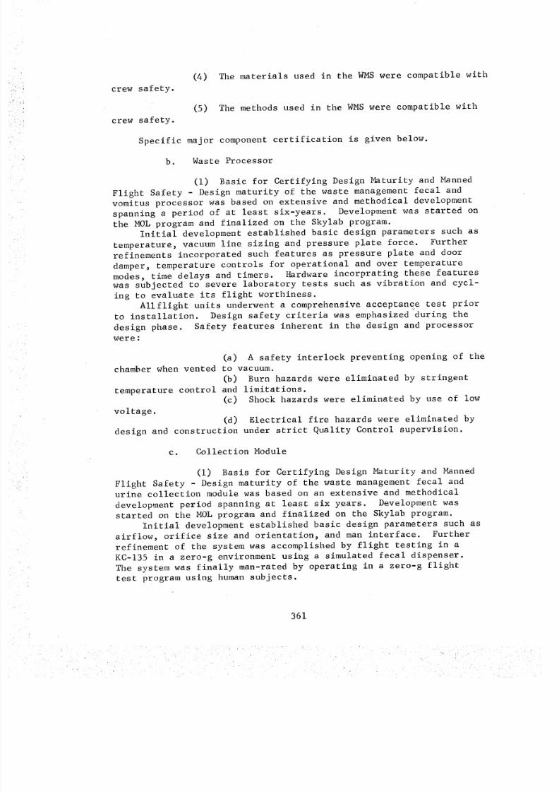
8/8/2019 MSFC Skylab Crew Systems Mission Evaluation
http://slidepdf.com/reader/full/msfc-skylab-crew-systems-mission-evaluation 385/397
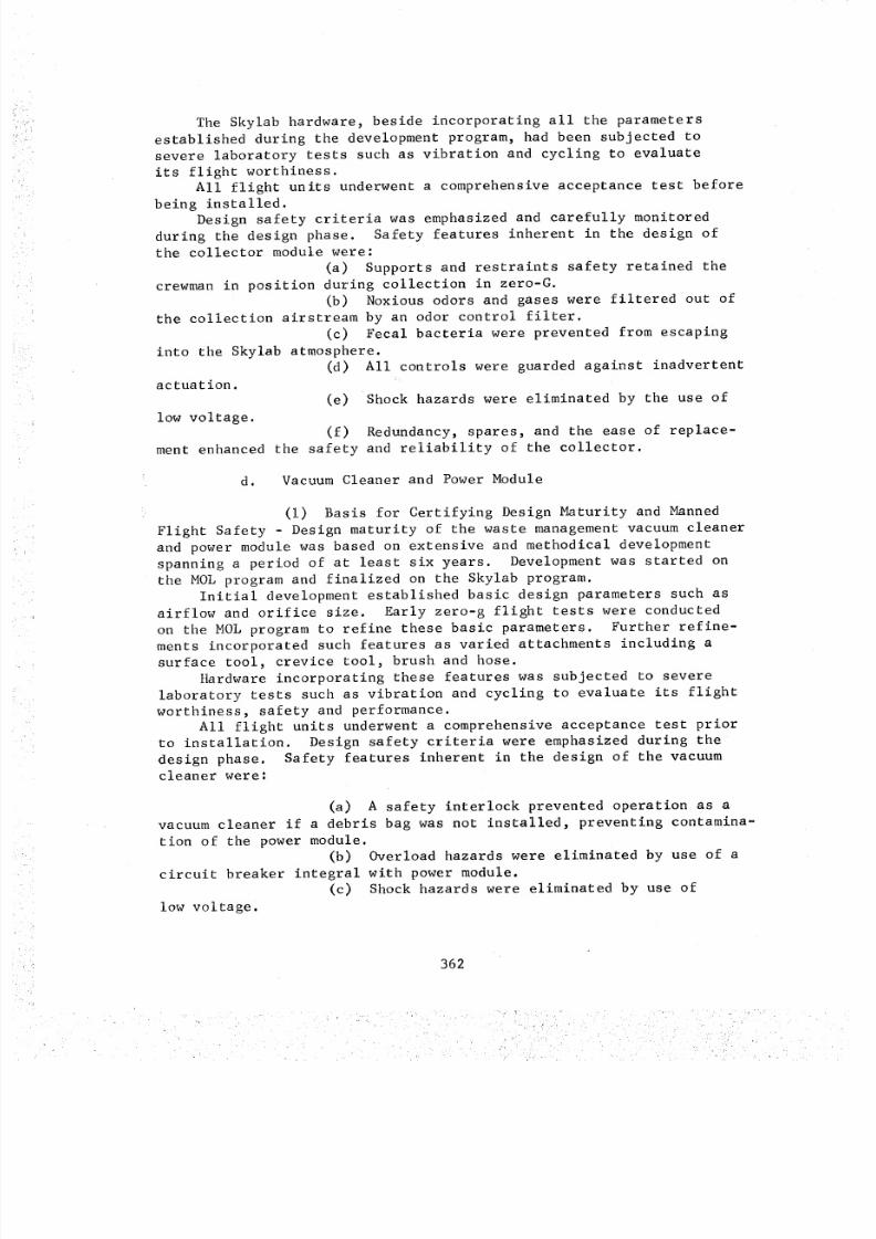
8/8/2019 MSFC Skylab Crew Systems Mission Evaluation
http://slidepdf.com/reader/full/msfc-skylab-crew-systems-mission-evaluation 386/397
The Skylab hardware, beside incorporating all the parametersestablished during the development program, had been subjected tosevere laboratory tests such as vibration and cycling to evaluateits flight worthiness.
All flight units underwent a comprehensiveacceptance test beforebeing installed.Design safety criteria was emphasizedand carefully monitoredduring the design phase. Safety features inherent in the design ofthe collector module were:
(a) Supports and restraints safety retained thecrewmanin position during collection in zero-G.
(b) Noxious odors and gases were filtered out ofthe collection airstream by an odor control filter.
(c) Fecal bacteria were prevented from escapinginto the Skylab atmosphere.
(d) All controls were guarded against inadvertentactuation.
(e) Shock hazards were eliminated by the use oflow voltage.
(f) Redundancy, spares, and the ease of replace-ment enhanced the safety and reliability of the collector.
d. VacuumCleaner and PowerModule
(i) Basis for Certifying Design Maturity and MannedFlight Safety - Design maturity of the waste management vacuumcleanerand power module was based on extensive and methodical developmentspanning a period of at least six years. Development was started onthe MOLprogram and finalized on the Skylab program.
Initial development established basic design parameters such as
airflow and orifice size. Early zero-g flight tests were conductedon the MOLprogram to refine these basic parameters. Further refine-ments incorporated such features as varied attachments including asurface tool, crevice tool, brush and hose.
Hardware incorporating these features was subjected to severelaboratory tests such as vibration and cycling to evaluate its flightworthiness, safety and performance.
All flight units underwent a comprehensive acceptance test priorto installation. Design safety criteria were emphasizedduring thedesign phase. Safety features inherent in the design of the vacuumcleaner were:
(a) A safety interlock prevented operation as avacuumcleaner if a debris bag was not installed, preventing contamina-tion of the powermodule.
(b) Overload hazards were eliminated by use of acircuit breaker integral with power module.
(c) Shockhazards were eliminated by use oflow voltage.
362
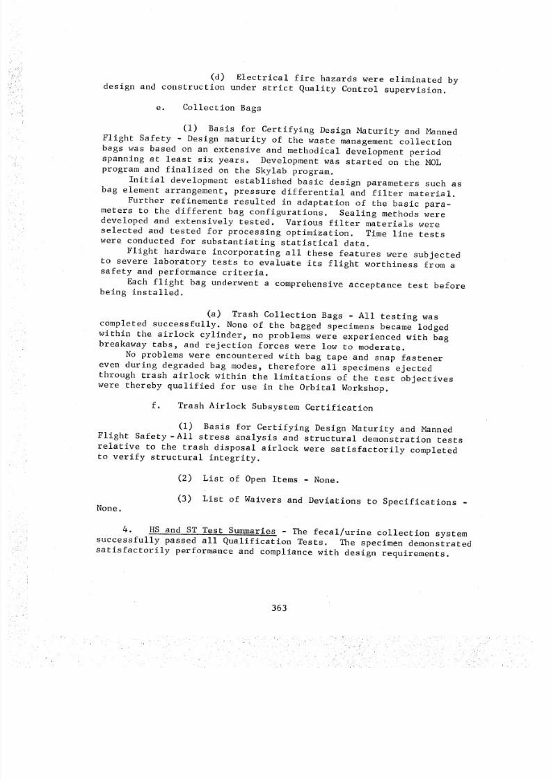
8/8/2019 MSFC Skylab Crew Systems Mission Evaluation
http://slidepdf.com/reader/full/msfc-skylab-crew-systems-mission-evaluation 387/397
(d) Electrical fire hazards were eliminated bydesign and construction under strict Quality Control supervision.
e. Collection Bags
(i) Basis for Certifying Design Maturity and MannedFlight Safety - Design maturity of the waste managementcollectionbags was based on an extensive and methodical development periodspanning at least six years. Developmentwas started on the MOLprogram and finalized on the Skylab program.
Initial development established basic design parameters such asbag element arrangement, pressure differential and filter material.
Further refinements resulted in adaptation of the basic para-meters to the different bag configurations. Sealing methodsweredeveloped and extensively tested. Various filter materials wereselected and tested for processing optimization. Time line testswere conducted for substantiating statistical data.
Flight hardware incorporating all these features were subjectedto severe laboratory tests to evaluate its flight worthiness from asafety and performance criteria.
Each flight bag underwent a comprehensive acceptance test beforebeing installed.
(a) Trash Collection Bags - All testing wascompleted successfully. Noneof the bagged specimens becamelodgedwithin the airlock cylinder, no problems were experienced with bagbreakaway tabs, and rejection forces were low to moderate.
No problems were encountered with bag tape and snap fastenereven during degraded bag modes, therefore all specimens ejectedthrough trash airlock within the limitations of the test objectiveswere thereby qualified for use in the Orbital Workshop.
f. Trash Airlock SubsystemCertification
(i) Basis for Certifying Design Maturity and MannedFlight Safety-All stress analysis and structural demonstration testsrelative to the trash disposal airlock were satisfactorily completedto verify structural integrity.
(2) List of Open Items - None.
None.(3) List of Waivers and Deviations to Specifications -
4. HS and ST Test Summaries - The fecal/urine collection system
successfully passed all Qualification Tests. The specimen demonstrated
satisfactorily performance and compliance with design requirements.
363
8/8/2019 MSFC Skylab Crew Systems Mission Evaluation
http://slidepdf.com/reader/full/msfc-skylab-crew-systems-mission-evaluation 388/397
Note: Redesign of the urine system from 2000 ml capacity to4000 ml capacity shortened someof the testing. This testing waspicked up later by HS-90.
The portable vacuumcleaner, waste processor, stowed urineseparator, urine dumpcompartment, fecal bag dispenser bag bundles,
and collection bag return assembly all successfully passed theirindividual qualification test requirements with no failures orproblems noted. Eachspecimen tested demonstrated satisfactoryperformance and compliance with its design requirements.
364
8/8/2019 MSFC Skylab Crew Systems Mission Evaluation
http://slidepdf.com/reader/full/msfc-skylab-crew-systems-mission-evaluation 389/397
B. Whole Body Shower
i. Testing - Various tests were conducted by MSFC on the whole
body shower (WBS) to develop and qualify the equipment and techniquesneeded for successful body cleaning.
a. Development - A study was made of a zero-g, whole bodyshower for use during the extended, manned orbital flights of the
Skylab series. Subsystem components were developed and tested to
verify conceptual proposals and to provide engineering data for sys-
tem design. A large effort was devoted to the development of an air-
water phase separator. Three concepts of air-water phase separation
were investigated with a mechanically driven centrifugal design
chosen over two passive types. A functionally high fidelity shower
system was assembled using a plexiglass shower enclosure for laboratory
testing. Shower water was collected using a vacuum pick-up systemand subsequently removed from the airstream for disposal with the cen-
trifugal - type air-water phase separator. The system was tested in
earth gravity and at both atmospheric and reduced air pressures. Test
results indicated that the system design was feasible for the orbital
workshop environment, and that an effective shower system could beassembled largely from modified OWS components.
b. Qualification - The qualification test was performed
on the Orbital Workshop Whole Body Shower, Water Bottle Module
Assembly (MSFC Dwg. No. 20M32509, S/N 002). These tests were per-
formed to determine if the Water Bottle Module Assembly could meet
the requirements established by the MSFC Specification Control Dwg.20M33020 and detailed in test procedure DOP-TMM-72-11.
Two components malfunctioned during the qualification testing.
During the life cycle test of the relief valve, the reseat pressuredecreased from the required 29-psig down to 22-psig. After 20 cycles
of the required i00 installation cycles, a retaining spring in one of
the quick release fasteners failed; however, the test was completedwithout further malfunctions.
In addition, an apparent leak in the diaphragm was caused by
entrapped air which required approximately 3-hours to disperse. Thiscondition was verified by S&E-QUAL.
The CCOH and destructive tests were performed after the system
tests. Results of these tests were satisfactory.
The failure of the quick release fastener spring was considered
insignificant since the water bottle could still be mounted satis-
factorily. Also, there are three quick release fasteners on the
bottle and one was sufficient to hold the bottle in zero "G". The
low reseat pressure on the relief valve is also a minor problem;therefore, the water bottle was considered qualified and recommended
for use on the Orbital Workshop Whole Body Shower System.
365
8/8/2019 MSFC Skylab Crew Systems Mission Evaluation
http://slidepdf.com/reader/full/msfc-skylab-crew-systems-mission-evaluation 390/397
8/8/2019 MSFC Skylab Crew Systems Mission Evaluation
http://slidepdf.com/reader/full/msfc-skylab-crew-systems-mission-evaluation 391/397
8/8/2019 MSFC Skylab Crew Systems Mission Evaluation
http://slidepdf.com/reader/full/msfc-skylab-crew-systems-mission-evaluation 392/397
b. Problem - During the initial ten-hour functional test
where the test chamber was controlled at 83_F, the power module
electronic controller overheated.
(i) Solution - A small orifice (.130/.134 DIA.) was
cut in the rubber duct previously added and air flow channeled acrossthe electronic module. This orifice provided 1.3 ACFM to the elec-tronic module which reduced the temperature approximately 12°F. To
reduce the temperature further, another orifice was cut to increase
the air flow but during the test verification run, the new orifice
did not reduce the temperature any appreciable amount. Therefore,
all remaining tests (life cycle) was run with one orifice only. The
resulting temperature was acceptable to the manufacturer of the power
module.
c. Problem - During a functional drying test performed
at JSC/NASA where approximately 6.85 ACMF (70% Op/30% N2, and 90°F
and 60°dp), was channeled through the PGA, approximately 75 grams of
moisture (water) remained in the suit after 5-1/2 hours of drying
using an open loop system. The excessive moisture (75 grams) was
considered by JSC/NASA to be not adequate for control of Fungal
contamination resulting in degradation of PGA materials.
(i) Solution - Change concept from drying two PGA's
at one time to one PGA at a time. Also, after drying PGA with air
flow power module, place in the PGA a sufficient amount of desiccant
to absorb the remaining moisture. A 6 1/2 foot length of Zitex
Dessiccant Assembly was added to the drying technique. Test data
that uses a PGA simulator (i/i0 volume of actual PGA) and a desic-
cant bag manufactured out of Zitex material and Silica Gel wastested with satisfactory results. Two vacuum drying tests using
the wet desiccant bags resulted in the desiccant being dried com-
pletely after ten hours.
6. Subsystem Conclusions
a. Summary of Capabilities Versus Requirements - Based
on the test results and the power module performance after life cycles
the air flbw rate and moisture removal has been demonstrated. Re-
moval of moisture remaining in the PGA after dynamic drying was also
demonstrated.It is concluded from test results that the PGA Drying Station
will meet all design requirements for use on the OWS.
Non e.
b. Summary of Open Problems and Plans for Corrective Action
c. Long-Duration Operational Capability - Not applicable.
368
8/8/2019 MSFC Skylab Crew Systems Mission Evaluation
http://slidepdf.com/reader/full/msfc-skylab-crew-systems-mission-evaluation 393/397
7. Subsystem Certification
a. Basis for Certifying Design Maturity and Manned Flight
Safety - All functional demonstration tests have been satisfactorily
completed to verify that moisture removal from PGA will be accomplished.
369
8/8/2019 MSFC Skylab Crew Systems Mission Evaluation
http://slidepdf.com/reader/full/msfc-skylab-crew-systems-mission-evaluation 394/397
D. Stowage
The Stowagesubsystem provided provisions for containment/re-straint for loose equipment in the OWSduring the launch/boost phaseand zero-g. Stowageprovisions consisted of containers, lockers,cabinets, film vault, food freezer/chiller and miscellaneous re-
straint provisions. Checkout for the Stowagesubsystem consisted ofIB96422, StowageProcedure, plus eighteen additional procedures,mostly experiments and water subsystem hardware.
All stowage locations were fit-checked during checkout exceptfor approximately 28 locations which were completed at the KSCbe-cause of the hardware not being available. In addition, 96 locationswere unstowed and the hardware was returned to the suppliers inaccordance with contractual direction. Twenty-five Ring Containerswere delivered to the KSCoutside the spacecraft. Fourteen of theRing Containers were fully stowed and five were partially stowed.
A precision inspection of the eleven ambient food containersdisclosed that someof the inside dimensions were outside the ICDtolerances. A Drawing Department Authorization was submitted. Dur-ing checkout, the installation and removal of the GFPfood rackswere successfully demonstrated in all eleven containers.
Pressure tests of the Mozite packing material (a closed cellmaterial) indicated a changeof volume with pressure change. Sincethis volume change could affect support of equipment during boostand/or in orbit, a series of tests were conducted to evaluate OWSuses. The test consisted of selecting critical installations ofpacking materials (Mosite, urethane, and fiberboard) and subjectingit to launch-to-orbital pressure profiles. Results of the testswere as follows:
oLaunch pressure - Support of equipment deemed satisfactory.
OOrbital pressure - Design changes were required on M-487stowage box. These changes were accomplished.
Interface with DSV7-303, OWS Crew Quarter Vertical Access Kit,
and DSV7-311, Habitability Support System Equipment Handling_Kit,was successfully demonstrated.
i. Stowage System - Crew equipment stowage was handled at KSC
by Test and Checkout Procedure (TCP) KO-3014. This test was begun
March 25, 1973, and completed April 2, 1973. Test objective of this
test were (a) to provide instructions for handling and pre-packaging
flight crew equipment in the cleanroom to support subsystem testing,
bench review, crew fit and function test, and flight stowage; (b)
to provide instructions for stowage of flight crew equipment in theOWS spacecraft for CCFF and flight; and (c) to create an installation
record of stowed flight crew equipment in support of launch opera-
tions. KO-3014 also provided CCFF procedures for the ring containers.All tests were conducted satisfactorily.
370
8/8/2019 MSFC Skylab Crew Systems Mission Evaluation
http://slidepdf.com/reader/full/msfc-skylab-crew-systems-mission-evaluation 395/397
8/8/2019 MSFC Skylab Crew Systems Mission Evaluation
http://slidepdf.com/reader/full/msfc-skylab-crew-systems-mission-evaluation 396/397
/J
/
E. Crew Systems
MDAC-W Crew Systems personnel performed mission crew tasks in
the subsystem tests to verify the crew interfaces• The checkout
tests performed in the Crew Systems area were:
• IB88207
e lB96426
elB94641
elB86424
elB94312
Food ManagementCrew Accommodations
Microbial Control Test Sampel
Crew Co_p_rtment Fit and Function (C2F 2)Delta C-F
No significant problems were encountered during checkout
The testing of the portable foot restraints (triangle shoes) and
the sleep restraints were deferred to KSC because late configuration
definition prevented flight articles from being available to Hunting-
ton Beach.
The flight crew performed the C2F 2 test in two (2) sessions and
a final bench check of the Ring Stowage Containers on 30 August 1972.
Fifteen (15) flight crewmen participated during these tests. There
were no significant problems; however, a number of Test Problem
Report (TPR) items were transferred to KSC for crew reverificationbecause of insufficient schedule time at Huntington Beach. These
were identified i_ _he Pre-Delivery Turnover Report. Significantsections of the C F Test and Checkout Procedures that were not
performed at Huntington Beach because of hardware unavailability
were:
eM487 Experiment Verification
eM172 Experiment Verification
e Rescue Drogue Verification
eStowage Fit Checks - Sleep Compartmente29 Stowage locations in other compartments
Crew Systems required no unique GSE. The interface with Model
DSV7-303, Crew Quarters Vertical Access Kit, and DSV7-311, HSS Equip-
ment Handling Kit, was successfully demonstrated•
i. KS-O010A Integrated Crew Compartment Fit and Functional
Test The Crew Compartment Fit and Functional Test (CCFF) at KSC was
performed to accomplish the verification of fit check and functional
sequences that were not satisfied during the first CCFF (IB86424) at
Huntington Beach due to lack of hardware or non-acceptable equipment
requiring modification and subsequent review. The specific tasks
performed by the Flight Crews, under the direction of assigned TestConductors were:
• Verification of the accessibility and operational suitability
of the previously non-verified stowed and installed OWS
module equipment provisions.
372
8/8/2019 MSFC Skylab Crew Systems Mission Evaluation
http://slidepdf.com/reader/full/msfc-skylab-crew-systems-mission-evaluation 397/397
• Verification of applicable mechanical and certain electricalfunctions of certain stowed and installed equipment, includingexperiments at in-flight using locations within the OWSmodule.
• Verification of fit check and/or functional interface withinthe OWSmodule of certain equipment launched in other vehiclesand designated for temporary or permanent OWSmodule occupancy.• Verification of selected critical tool interfaces.
• Verification of selected in-flight maintenance tasks usingorbital spares.
• Demonstrate and verify functional performance of designatedHabitability Support System (HSS) operations as comprised bythe test environment (IG, 14.7 psia, etc.).