Embed Size (px)
Citation preview

8/8/2019 MSFC Skylab Structures and Mechanical Systems Mission Evaluation
http://slidepdf.com/reader/full/msfc-skylab-structures-and-mechanical-systems-mission-evaluation 1/348
NASA TECHNICAL October1974
MEMORANDUM - #
" &
NPSATMX-(_1824V"
[; •
I-_ "==__= _._ _'_L -,,= ___.__
_llP_>'; I,; _ ' "#<-_'_-. _-_.- _
(RlSl-TM-Z-64821} MSPC SKILIB STROCTURES i75-10968t
&ND MECEINICIL SYSTEMS MISSlOi E¥&LUAT!OR
(NA$&} 3_8 p HC $9.50 CSCL 22C
Unclas ] i
G3/12 53892
MSFCSKYLABSTRUCTURESNDMECHANICAL i
SYSTEMSMISSIONEVALUATION iSkylab Program Office i
NASA I
GeorgeC. Marshall 5pace FlightMarshall _?aceFlight 6enter, Alabama
hISFC - Form ,_190 (Rev June 1971)
j.jr .... ' -- , ................ l I / I I i ,' _'_'_---. ........ 11[I - . I .................. i,i I 1 J , "
8/8/2019 MSFC Skylab Structures and Mechanical Systems Mission Evaluation
http://slidepdf.com/reader/full/msfc-skylab-structures-and-mechanical-systems-mission-evaluation 2/348
1 I i i , ] I ,Y
, TI[CHNICAL REPORT _;TANDAI_D TITLE IMAGE
, REPORTNO. 12. G,Ve_NM_NVACCESSIONO. S. RECIPIENT'$CAT#J.OGO,ASA TMX-64824
4 TITLE AND SUBTITLE S. REPORT DATEOctober 1974
MSFC Skyiab Structures and Mechanical Systems s. PERFORMINGRGANIZATIONODE
t Mission Evaluation
7. AUTHOR(S) 8. PERFORMING ORGAN:ZATION REPOR r.
9. PERFORMING ORGANIZATION NAME AND ADDRESS 10. WORK UNIT NO.
George C. Marshall Space Flight Center l. CONTalACTRGRANTNO.
Marshall Space Flight Center, Alabama 35812 Is.TY_0e REPOt:"a PEmOOcove,go
12 SPONSORING AGENCY NAME AND ADDRESS
TechnLcal Memorandum
National Aeronautics and Space AdmLnLstratLon 14. SPO,SOmNGAGENCYCODE
Washington, D. C.. 20546_5. SUPPLEMENTARY NOTES
Prepared by Structures and Propulsion Laboratory, Structures Division
16.ASSTRACT This report presents a performance analysis for structu_l andmechanical major hardware systems and components. Development back-
ground testing, modifications, and requirement adjustments are presented
where considered pertinent.
Functional narratives are provided for comparison purposes as are
predicted design performance criterion. Each item is evaluated on an
individual basis: that is, (1) history (requirements, design, manufacture,
and test); (2) in-orbit performance (description and analysis); and
(3) conclusions and recommendations regarding future space hardware
application.
Overall, the structural and mechanical performance of the Skylab
hardware was outstanding. There were anomalies, some expected, someunexpected, but none of such consequence that on-orbit workarounds
and/or new hardware development did not solve the problems.
EDITOR'S NOTE
Use of trade names or names of manufacturers in this report does not constitute
an official endorsement of such products or manufacturers, eLther expressed or
implied, by the National Aeronautics and Space Administration or any agency of
the United States Government.
17. KR_ WORDS 18. DIlTRIIUTION STATEMENT
UNCLASSIFIED - .UNLIMITED
1 i ' , ' IR. G Eudy . /_
19. SECUI_ITY GLASSIF. (d thi, Np_t_ " 20. SECURITY CLASSIF. (of thle palliD) 121-. NO. OF PAGES 22. PRICE
UNCLASSIFIED UNCLASSIFIED [ 348 _TISm
M.qFr' - F-,,. _:ill 11(Rev l)eremhe, I# 1| ) FOr lalo by National Teeh_ell Infnrmall_n gervlee, 9prinsfleid, Virldnl¢ _21$ I
• • il t
8/8/2019 MSFC Skylab Structures and Mechanical Systems Mission Evaluation
http://slidepdf.com/reader/full/msfc-skylab-structures-and-mechanical-systems-mission-evaluation 3/348
! ! _ i 1 I 1 Ti i i I
ACI_OWLED_J4ENTS
The data used to compile this report were furnished by theCeors e C. Marshall Space Flight Center Astronautics Laboratory, theMcDonnell Douglas Astronautics Company (Eastern and Western Divisions),the Martin Marietta Corporation, and the Teledyne Brown Ensineerlns,Aerospace Support Division.
ii
8/8/2019 MSFC Skylab Structures and Mechanical Systems Mission Evaluation
http://slidepdf.com/reader/full/msfc-skylab-structures-and-mechanical-systems-mission-evaluation 4/348
_T
+ TABLE OF CONTENTS
'_ A_'FRA_T ................................. i_J
; ACKNOW LE_ ;I.:MENTS. ............................ ii
/,
TABI,E OF CONTENTS ............................ iii
I,IST OF ILI,IISTIIAT1ONS .......................... ix
lbECFION I. SIIMMARY ........................... 1
: A. SKYLA_ REQUIREMENTS AND CONFIGURATION .......... 1B. STRUCIURES AND MECHANICAL HARDWARESYNOPSIS ....... 4
SI!CI'ION II, INTRODUCTION ........................ 7
A. PURPOSE ......................... 7
B. SCOPE .......................... 7
Sl!(7rION 111 .API'I,ICABI,E DOCUMENTS .................... 8
SECrION IV. SKYI,AB VI!NTILATION ilAEDWARE ................. ll
A. (;LNERAL REQIIIREMENTS .................. 11B. PEVELOPMF.NTAND TESTING ................. 11
C. _4ISSION PERFORMANCE ................... 11
i). ANOMALIES ........................ 12
E. RECOMMENDATIONS ..................... 12
SI!CFION V. SI"fLAB MODULES AND HARDWARE................. 1S
A. AI RLOCK ......................... 15
1. Basic Requiren_ents and Configuration Evolution 1S2. Structures ..................... 15
a. Pressure vessel ................. 17
b. Bending moment and axial loads ......... 175. Natural Environments ................ 17
4. Mechanical Components ................ 18a. llatches ..................... 18
(I) Extravehicular activity hatch ....... 18
(2) Internal hatches .............. 18
b. Pressure equalization valves ........... 20c, Windows and covers ............... 21
d. Discone antennas ............... 25
S. Environmental Control System ............ 27
a. 02N 2 system ................... 27: fl) 02 tanks .................. 30
i, (2) Filter/relief valve assembly ........ 30
(3) 0 2 pressure regulator assembly ....... 50
(4) Cabin pressure regulator .......... 31
(5) N2 storage tanks .............. 33
(t,) N2 pressure re_,ulator ........... 33
(7) I1_O tank pressure regulator ........ 56
e
iii
iI
8/8/2019 MSFC Skylab Structures and Mechanical Systems Mission Evaluation
http://slidepdf.com/reader/full/msfc-skylab-structures-and-mechanical-systems-mission-evaluation 5/348
TABLEOF CONTENTS(cont)b. Thermal control system ............. 56
(I) Pump assemblies ............. 37(2) Temperature control valve (47 °) ..... 59(5) Tempe:ature control valve (40") ...... 42
(4) Thermal capacitor ............ 43(5) Coolant filters .............. 43(6) By-pas_ valve ............... 45(7) Radiator by-pass and relie£ valve ..... 45
(8) Radiator .............. -- - - 47{9) Coolant system reservicing equipment . . : . 49
c. Suit cooling system ............ 52(I) Water p_,_p ............... 54(2) EVA/IVA liquid gas separator ....... 54(3) Water tank ................. 55
d. Telescope mount control and display console/ EREPcoolant system .............. 56
e. Condensate system .., .............. 60£. Quick disconnects .............. 65
B. FIXED AIRLOCK SHROUD .................. 64C. TELESCOPE MOUNT..................... 66
I. General Description ............... 66
2. Telescope Mount Structural Systems ......... 663. Aperature and Film Retrieval Doors ......... 79
a. Film retrieval doors .............. 79
b. Aperature doors ................ 85
(1) SO54 aperature door ............ 85(2) SOSSA aperature door ........... 86(3) SO56 aperature door ............ 86(4) SO52 aperature door ............ 86
(S) SO82A aperature door ........... 87(6) H alpha 2 aperature door ......... 87
(7) SO82B aperature door ......... 874. Thermal Control System Hardware .......... 90S. Fxtravehicular Activity Hardware .......... 95
a. Telescope mount hand rails ........... 98b. Extravehicular activity foot restraints . . . 98c. Umbilical Clamps ........ 9gd. Center and sun end work'station trees _nd t_ee
receptacles .................. 100e. Camera transfer equipment ........... 195f. Temporary stowage components .......... 106
D. TELESCOPE MOUNT DEPLOY_NT ASSEMBLY .......... 107
1. Deployment Assembly Structure ........... 1072. Deployment Assembly Ordnance Release ,System 110
5. Deployment System ................. 114
E. PAYLOAD SHROUD ........ ._ .__... 1201. Basic Requirements and Configuration Selection . • 1202. Payload Shroud Structures ............. 120
a. Axial loads -rid bending moment ....... . 120b. Acoustlcal data ................ 125
iv
I j j J J
8/8/2019 MSFC Skylab Structures and Mechanical Systems Mission Evaluation
http://slidepdf.com/reader/full/msfc-skylab-structures-and-mechanical-systems-mission-evaluation 6/348
1
TABLE OF CONTENTS CCONT)
3. Natural Environments Design ............. 125
4. Separation System .................. 129
a. Discrete latches (latch actuator) ........ 129
b. Thrusting joint ................. 132c. Contamination .................. 158
5. Conclusions and Lessons Learned ........... 138
F. DOCKING ADAPTER .................. 140
1. Basic Requirements and Configuration Evolution . 1402. StructuTes .................... 143
a. Pressure vessel ................ 143
b. Loads ................... _44
c. Acoustical data ................. 147
d. Vibration data ................. 148
3. Natural Environments Design ............. 1S1
4. Mechanical Components ................ 153a. Windows .................... 153
b. Covers ..................... 157c. Docking ports .................. 161d. Hatches ..................... 163
o. Pressure equalization system .......... 165
S. Hounting Provisions and Installations ........ 166
a. Telescope mount control and display panel .... 166b. Earth resources hardware ............ 167
c. L-band truss .................. 167
d. Foot restraints ................ 168
e. Control and display console body restraint device 168
6. Stowage ....................... 170a. Film vaults ................... 170
b. Stowage containers ............... 171
7. Mechanical Systems ................. 174a. Ventilation systems ............... 174
b. Telescope mount control and display panel/earth
resources coolant system ............ 178
c. Docking adapter vent system ........... 185
d. MS12/M479 Experiment vent systems ........ 188
8. Rate Gyro 6-Pack ................ 1949. Conclusions and Recommendations .......... 195
G. WORKSHOP ...................... 198
1. Introduction .................. 198
2. Wardroom Window ................... 200'
a. General requirements ............. 200
b. Mission performance ............... 200
c. Anomalies .................... 200(1) Workaround ................. 200
(2) 'troubleshooting .............. 203d. Recommendations ............... 203
3. Solar Array System ............... 204
a. General Requirements .............. 204
b. Development and Testing ............. 204
t
8/8/2019 MSFC Skylab Structures and Mechanical Systems Mission Evaluation
http://slidepdf.com/reader/full/msfc-skylab-structures-and-mechanical-systems-mission-evaluation 7/348
TABLEOF CONTENTS(CONT)
(1) SA-14 wing release ............ 204(2) SA-15 wing release ............. 205(3) SA-17 solar array system ream faring release 205
(4) ST-24 expandable tube and tension strap . 206(5) Acoustic vent nodule ........... 206
(6) Actuator/damper ........... 206c. Mission performance ............. 211d. Anomalies .................. 211e. Recommendations ............... 216
4. Meteoroid Shield . . .............. 216
a. General requirements ............. 216b. Subsystem configuration ............ 217c. Development and testing ............. 228d. Mission performance .............. 237e. Conclusions .................. 258
5. Workshop _ntry Hatch ............... 259
a. General requirements ............ 239b. Mission performance ........... 239c. Anomalies .................. 239d. Recommendations ................ 240
6. Scientific Airlock ............. : . . 241
a. General requirements ............. 241b. Mission performance ............... 241c. Anomalies . . ................. 241d. Recommendations ................. 245
7. Trash Airlock .................... 243
a. General requirements ............. 243b. Mission performance .............. 243c. Anomalies ................... 244d. Recommendations ................ 244
8. Thermal Shield ................. 246a. Candidate designs .............. 246b. Components .............. 246
(1) Two deployment poles ........ 246(2) Two clotheslir, e assemblies ....... 249(3) One base platc assembly ....... 249(4) One thermal shield ............ 249(5) On foot restraint plate asscmbly ...... 255
c. Testing ..................... 253d. Flmctional performance ............. 255
9. Waste Management System ............. 255a. Fecal collection and processing ........ 255
(I) General requirements ............ 255
(a) Fecal collection ........... 255(b) Vomltus collection .......... 256
(c) Waste p_ocessor ............. 256• (2) Mission, perfo_-mance ............ 256
(3) Anomalies . .\ ............... 257(4) Recommendations ............. 257
vi
8/8/2019 MSFC Skylab Structures and Mechanical Systems Mission Evaluation
http://slidepdf.com/reader/full/msfc-skylab-structures-and-mechanical-systems-mission-evaluation 8/348
8/8/2019 MSFC Skylab Structures and Mechanical Systems Mission Evaluation
http://slidepdf.com/reader/full/msfc-skylab-structures-and-mechanical-systems-mission-evaluation 9/348
TABLE OF CONENTS (CONT)
(1) Pre-filtration for valves ......... 293
(2) Filter location .............. 293(3) Use of orifices .............. 293
(4) Leakage ................ 293
(s) componentife .............. 293(6) Redundancy ................ 293
12. Thruster Attitude Control System ......... 294
a. General requirements .............. 294
b. Hission performance ............. 294c. Anomalies .................. 294
d. Recommendations .............. 294
13. Special Projects Hardware ............ 295a. Evaluation .................. 295
14. Suit Drying Station ............... 301
a. General requirements ............ 301
b. Mission performance ............ 301c. Anomalies .................. 501
IS. Whole Body Shower ................ 303
a. Description ................. 303
b. Component evaluation ............. 303
16. Liquid Dump Systems _ ............... 320a. General requirements .............. 320b. Mission per£ormance .............. _20c. Anomalies ................. 324
d. Recommendations ................ 325
17. Vent Systems . . .................. 325a. Habitability _rea ............... 325
(I) General requirements .......... 325
(2) Mission performance ............ 327(3) Anomalles ................ 327
(4) Recoumendat ions .............. 328
b. Waste tank ................. 328
(I) General requirements : 328
(2) Mission performance ............ 328
18. Vacuum Support System ............... 329
a. General requirements .............. 329
b. Mission performance .............. 329c. Anomalies ................... 329
19. Pneumatic System ................_ . 329
a. General requirements ............. 329
b. Mission performance .............. 331
viii
, I
l
8/8/2019 MSFC Skylab Structures and Mechanical Systems Mission Evaluation
http://slidepdf.com/reader/full/msfc-skylab-structures-and-mechanical-systems-mission-evaluation 10/348
I ! Y v I I I
I ' i , , . , I
!. LIST OF ILLUSTRATIONS' ANDTABLES
: Figure/Table Tit le Page
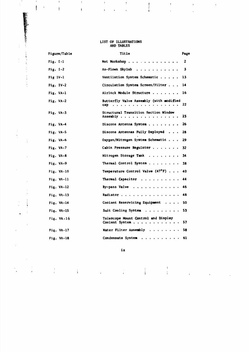
Fig. I-I Wet Workshop .............. 2
Fig. I-2 As-Flown Skylab ........... 3
Fig IV-I Ventilation System Schematic ..... 13
Fig. IV-2 Circulatlon System Screen/Filter . . . 14
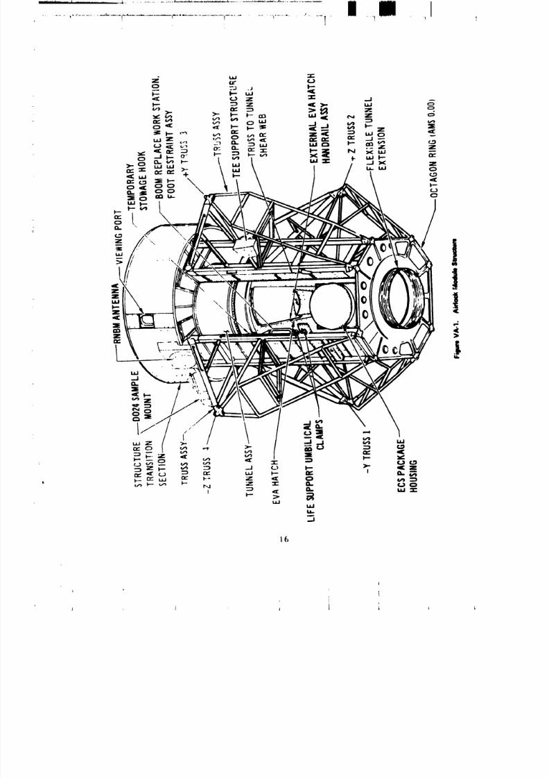
Fig. VA-1 Airlock Module Structure ....... 16
Fig, VA-2 Butterfly Valve Assembly (with modified
cap ................. 22
Fig. VA-3 Structural Transition Section Window
Assembly ............... 23
Fig. VA-4 Discone Antenna System ........ 26
Fig. VA-5 Discone Antennas Fully Deployed . . • 28
Fig. VA-6 Oxygen/Nitrogen S,.tstem Schematic . . . 29
Fig. VA-7 Cabin Pressure Regulator ....... 32
Fig. VA-8 Nitrogen Storage Tank ........ 34
Fig. VA-9 Thermal Control System ........ 38
Fig, VA-IO Temperature Control Valve (47°F) . . • 40
Fig. VA-11 Thermal Capacitor ........ 44
Fig. VA-12 By-pass Valve ............ 46
Fig. VA-13 Radiator ............... 48
Fig. VA-14 Coolant Reservlclng Equipment .... SO
Fig. VA-IS Suit Cooling System ......... 53
Fig. VA-16 Telescope Mount Gontrol and DisplayCoolant System ............ 57
Fig. VA-17 Water Filter Assembly ........ 58
Fig. VA-18 Condensate Systen .......... 61
ix
8/8/2019 MSFC Skylab Structures and Mechanical Systems Mission Evaluation
http://slidepdf.com/reader/full/msfc-skylab-structures-and-mechanical-systems-mission-evaluation 11/348
f I I 1 I 1 !t t t , , I , ,
LIST OF ILLUSTRATIONS
AND TABLES (CENT)
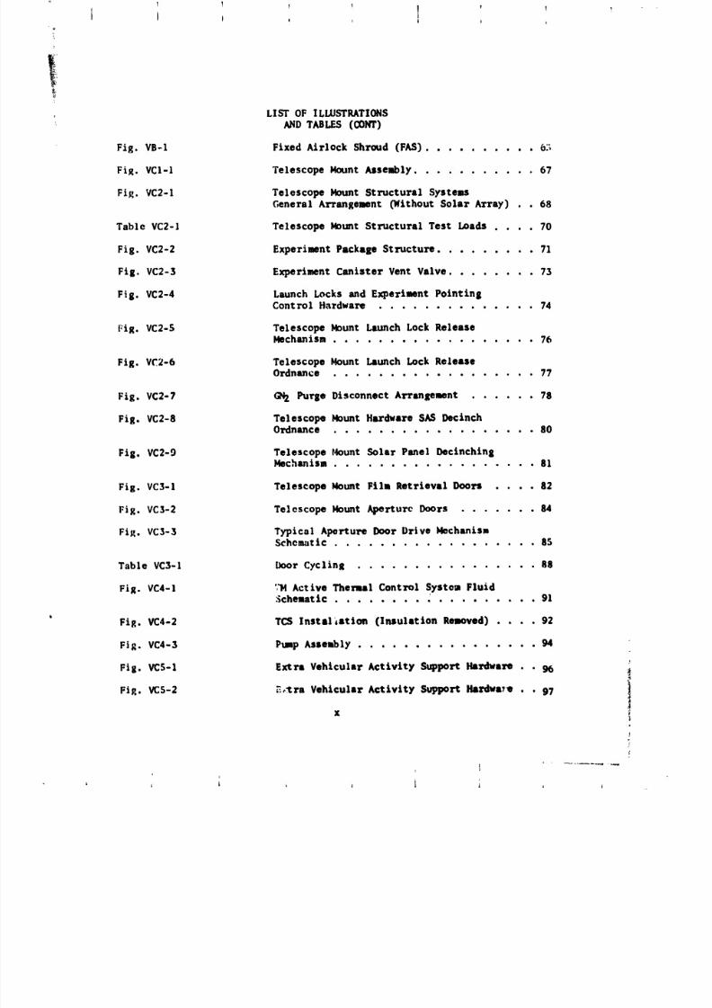
Fig. VB-1 Fixed Airlock Shroud (FAS) .......... 6._
Fig, VCI-I Telescope Mount Assenbly ........... 57
Fig. VC2-1 Telescope Mount Structural SysteasGeneral Arrange:tent (Without Solar Array) . . 68
Table VC2-1 Telescope Mount Structural Test Loads .... 70
Fig. VC2-2 Experiaent Package Structure ......... 71
Fig. VC2-5 Experiment Canister Vent Valve ........ 75
Fig. VC2-4 Launch Locks and Experiment PointingControl Hardware ............. 74
Fig. VC2-5 Telescope Mount Launch Lock ReleaseMechanism .................. 76
Fig. VC2-6 Telescope Mount Launch Lock ReleaseOrdnance .................. 77
Fig. VC2-7 GN Purge Disconnect Arrangement ...... 78
Fig. VC2-8 Telescope Mount Hardware SASDecinchOrdnance .................. 80
Fig. VC2-9 Telescope Mount Solar Panel Decinchin 8Mechanism .................. 81
Fig. VC3-1 Telescope Mount Filt Retrieval Doors .... 82
Fig. VC3-2 Telescope Mount Aperture Doors ....... 84
Fi_. VC3-3 Typical Aperture Door brive )4echanisu$cho_tic .................. 85
Table VC3-1 Door Cycling ................ 88
Fig. VC4-1 ',_ Active Thermal Control Systea Fluid.Schemattc .................. 91
FiR. VC4-2 TCS Instal,ation (Insulation Restored) .... 92
Fig VC4-3 PumpAssembly 94
Fig. VCS-I Extra Vehicular Activity Support Hardware . . 9b
Fig. VC5-2 _.,._ra Vehicular Activity Support Hardwa71 . . 97
x
I
8/8/2019 MSFC Skylab Structures and Mechanical Systems Mission Evaluation
http://slidepdf.com/reader/full/msfc-skylab-structures-and-mechanical-systems-mission-evaluation 12/348
T I + ] f ' ,i
I
+ LIST OF ILLUSTRATIONS" ANDTABLES03NT)
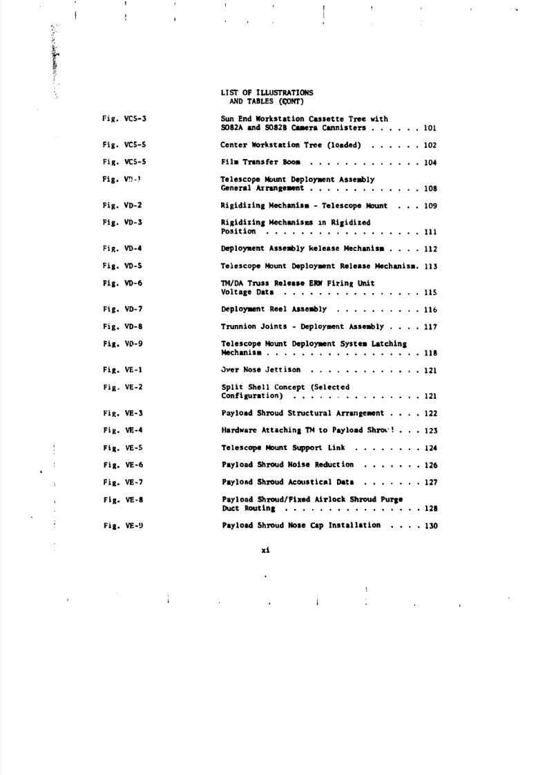
Fig. VCS-3 Sun End Norkstation Cassette Tree withSO82A and SO82B Cmera Cannisters ...... 101
Fig. VCS-S Center Norkstation Tree (loaded) ...... 102
Fig. VCS-S File Transfer Boom ............. 104
Fig. V_-I Telescope Mount Deployment AssemblyGeneral A_ranRHmnt ............. 108
Fig. VD-2 Rigidizing Mechanism - Telescope Mount . . . 109
Flg. VD-3 Rigidizlng Mechanisms In Rigidlzed
Position .................. III
Fig. VD-4 Deployuent Assembly kelease Mechanism .... I12
Fig. VD-S Telescope Mount Deployment Release Mechanism. 113
Fig. VD-6 I_I/DA Truss Release EI_ Firing UnitVoltage Data ................ 115
Fig. VD-7 Deployment Reel Assembly .......... 116
Fig. VD-S Trunnion Joints - Deployment Assembly .... 117
FiR. VD-9 Telescope Mount Deployment System Latching
Mechanism .................. I18
FiR. VE-I Over Nose Jettison ............. 121
Fig,, VE-2 Split Shell Concept (SelectedConfiguration) .............. 121
FiR. VE-3 Payload Shroud Structural Arrangemnt .... 122
Fig. VE-4 Ha_lwar_ Attaching TM to Payload Shrov ! . . . 123
! FiR. VE-S Telescope Mount Support Link ........ 124
: FiR. rE-6 Payload Shroud Noise Reduction ....... 126
FiR. VE-7 Payload Shroud Acoustical Data ....... 127
Fig. VE-8 Payload Shroud/Fixed kirlock Shroud Pu_eDuct Routing 12S
+
+ Fi R. VE-9 Payload Shroud Nose Cap Installation .... 130
xi
t
i
8/8/2019 MSFC Skylab Structures and Mechanical Systems Mission Evaluation
http://slidepdf.com/reader/full/msfc-skylab-structures-and-mechanical-systems-mission-evaluation 13/348
I f ! 'J
LIST OF ILLUSTRATIONS
ANDTABLES (CONT)
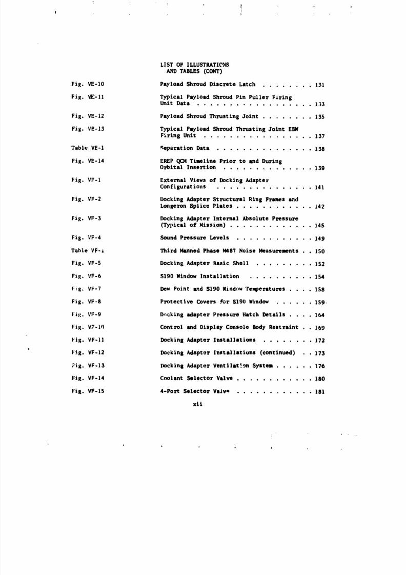
Fig. VE-IO Payload Shroud Discrete Latch ........ 131
Fig. _-II Typical Payload Shroud Pin Puller FiringUnit Data .................. 133
Fig, VE-I2 Payload Shroud Thrusting Joint ........ 13S
Fig. VE-I3 Typical Payload Shroud Thrusting Joint EBW
F'_ring Unit ................. 137
Table VE-I _eparatlon Data ............... 138
Fig. VE-14 EREP(_24 Timeline Prior to and DuringOrbital Insertion .............. 139
Fig. VF-I External Views of Docking AdapterConfigurations ............... 141
Fig. VF-2 Docking Adapter Structural Ring Frames madLongeron Splice Plates ............ 142
Fig. VF-3 Docking Adapter Internal Absolute Pressure(Typical of Mission) ............. 145
Fig. VF-4 Sound Pressure Levels ............ 149
Table VF-i Third Manned Phase IMg7 Noise Measurements . . IS0
Fig, VF-S Docking Adapter Basic Shell ......... IS2
Fig, VF-6 SlgO Window Installation .......... IS4
_:ig, VF-7 Dew Point and S190 Window Temperatures .... Isg
Fig. VF-8 Protective Covers tot S190 Window ...... IS9.
Fill. VF-9 b,',cking adapter Pressure Hatch Details .... 164
Fig. V_-I¢) Control and Display Console Body Restraint . . 169
Fig. VF-II Docking Adapter Installations ........ }72
Fig. VF-12 Docking Adaptor Installations (continued) • 173
_ig. VF-13 Docking Adaptor Ventilate.on System ...... 176
Fig. VF-14 Coolant Selector Valve ............ 180
Fig. VF-IS 4-Port Selector Valv* ............ lgl
xii
J J _ I i i l
8/8/2019 MSFC Skylab Structures and Mechanical Systems Mission Evaluation
http://slidepdf.com/reader/full/msfc-skylab-structures-and-mechanical-systems-mission-evaluation 14/348
1
ILLUSTRATIONSIST OF
; AND TABLES (CONT)
3: Fig. VF-16 Vent System ................ 184
Fig. VF-17 Vent Panel ................. 1852
Fig mblyVF-18 4-1nch Vent Valve Asse ......... 186
Fig. VF-19 4-inch Chamber Vent Valve • • . _ . . . 190iQe
_! Fig. VF-20 _ _12/M479 Vent System ........... 190
Fig. VF-21 Six-pack Rate Gyro Assembly ......... 196
Fig. VGI-I Workshop Major Structural Assemblies .... 199
Fig. VG2-1 Wardroom Window ............... 201
Fig. VG2-2 Evacuation Configuration .......... 202
Fig. VG3-1 Acoustic Vent Module ............ 207
Fig. VG3-2 Acoustic Vent Door ModuleAssembly ..... 208
Fig. VG3-3 Acoustic Vent Module Rellef Valve ...... 209
Fig. VG3-4 Actuator/Damper ............... 210
Fig. VG3-5 Beam Fairing and Wins Section Deployment . . 212
Fig. VG3-6 Beam Fairing and Wing Section Beploymlnt . . 213
Fig. VG3-7 Ord_nce Profile .............. 214
Fig. VG3-8 SAS Wing #i Restrained by a Piece of the
Meteoroid Shield .............. 215
Fig. VG4-1 Meteoroid Shield .............. 219
_ Fig. VG4-2 Meteoroid Shield Ordnance Schematic and
Cross Section View ............. 220
_ Fig. VG4-3 Meteoroid Shield Deployment Mechanism • • • 221
Fig. VG4-4 Meteoroid Shield Partially Deployed .... 222
Fig. VG4-5 Meteoroid Shield Deployed for Orbit • • • , 223
Fig. VG4-6 Meteoroid Shield Deployment Ordnance and
Foldout Panels ............... 224
: xlll
!
j i
I _ J J
8/8/2019 MSFC Skylab Structures and Mechanical Systems Mission Evaluation
http://slidepdf.com/reader/full/msfc-skylab-structures-and-mechanical-systems-mission-evaluation 15/348
1 ! f ! _ ,
!!{
LIST OF ILLUSTRATIONS
AND TABLES CCONT)
Fig. VG4-7 Meteoroid Shield Ttmnel Straps and Butterfly
i,Hinge Assembly ................ 225
i
Fig. VG4-8 Meteoroid Shield Trunnion Assembly ....... 226
Fig. VG4-9 Meteoroid Shield Boot 227
Fig. VG4-10 Meteoroid Shield Ordnance Tension Strap Assembly 229
Fig. VG4-11 Meteoroid Shield Ordnance Strap Design Evolution 250
Fig. VG4-12 Meteoroid Shield Deployment Latch Assembly , . . 252
Fig. VG4-15 Meteoroid Shield Zero g Deployment Kit ..... 255
Fig. VG4-14 Meteoroid Shield Mechanical Deployment Panel . . 255
Fig. VG6-1 Scientific Airlock ............... 2_2
Fig. VG7-1 Trash Airlock ................. 245
Fig. VG8-1 MSFC Thermal Shield .............. 247
Fig. VGS-2 Deployment Pole ................ 248
Fig, VGS-3 Clothesline Assembly .............. 250
Fig, VG8-4 Base Plate Assembly .............. 251
Fig. VG8-5 Thermal Shield Assembly ............ 2S2
Fig. VG8-6 Foot Re,'traint AsJembly ............ 254
Fig. VG9-1 Waste Processor Module ............. 258
Fig VG9-2 Separator 261
Fig. VGg-3 Urine Collection Drawer Suction Line Flange
! Launch Condition, Failure, and Repair ..... 265
_' Fig VG9-4 Vacuum Cleaner 266• e • • • • e • • • • • • • • • •
rig. VG9-5 Cellectlon Module 268Q Q • • • • • • • • i • • • • •
Fig VG9 Odo Filte "269-6 r Control r ..............
Fig. VGIO-I System Schematic ................ 271
* xiv
i
I _ i I 1 J i
8/8/2019 MSFC Skylab Structures and Mechanical Systems Mission Evaluation
http://slidepdf.com/reader/full/msfc-skylab-structures-and-mechanical-systems-mission-evaluation 16/348
! I I { I I IL i i i i
• ' I I i !
LIST OF ILLUSTRATIONS
ANDTABLESCOST)
Fig. VGIO-2 Water Container Assembly ............ 272
Fig. VGIO-5 Deionization Filter .............. 274Fig. VGlO-4 Purification Equipment (Iodine Injector) .... 276
Fig. VGIO-S Portable Water Tank (PNT) .......... 277
Fig. VGIO-6 Heater Resistance Profile ........... 279
Fig. VGIO-7 Wardroom and _ Water Heater ........ • 280
Fig. VGIO-8 Washcloth Squeezer ............... 281
f
Fig. VGII-I Refrigeration System Schematic ......... 285
Fig. VGll-2 Plume Shield and Release Mechanism ....... 286
_ Fig. VGll-3 Refrigeration Pump Assembly • • • • • • • • • • 288
Fig. VGll-4 Chiller Control Valve ............. 289
i Fig. VGII-S Thermal Capacitor .............. 290i
Fig. VGI1-6 Radiator Bypass Valve ............ 291
_' Table VG15-1 Tool/Task _cco_llshment Comparison 296
Fig. VGIS-I Universal Tool ................. 298
i Fig. VGI3-2 Shear ..................... 297
: Fig. VGI3-5 Cable Cutter ................. 500
Fig. VG13-4 Breaking Beam Fairing Actuator Damper Clevis . 302
J
i Fig. VG15-1 Workshop Shower ............... 304
Fig. VG15-2 Water Bottle Module ............. 506
Fig VGI5-3 Whole Body Shower Stall (Operational) .... 508
Fig. VGI5-4 Shower Head Assembly ............. 510
FiR. VGIS-5 Suctlon Head Assembly ............ 312
XV
8/8/2019 MSFC Skylab Structures and Mechanical Systems Mission Evaluation
http://slidepdf.com/reader/full/msfc-skylab-structures-and-mechanical-systems-mission-evaluation 17/348
q
! i _ I
LIST OF ILLUSTRATIONS
ANDT_B_ZSco_)
Fig. VG1S-6 Colloction Box Assembly ............ 314
Fig. VG15-7 Cen_ri£ugal Separator ............. 316
Fig VGIS-8 Hydrophobic Filter Assembly .... 318
Fig '/G16-1 liquid DumpSystems 321 :
Fig. VG16-2 Liquid Drop Heater Probe Installation ..... 322
Fig. VG16-3 Liquid Dump Probe ............... 323 +
Fig. V(;16-4 Possible Mechanisms of Flow Reduction Stoppage 326
Fi_. VGIS-1 LBNPDVacuum Source Modification ....... 330
xvi
................. i I .......
J i l i J I i ,
8/8/2019 MSFC Skylab Structures and Mechanical Systems Mission Evaluation
http://slidepdf.com/reader/full/msfc-skylab-structures-and-mechanical-systems-mission-evaluation 18/348
!: 1 1 1 l ! 1 ,
SECTION I. SU_t&RY
A. Skylab Requirements and Configuration
Skylab structural and mechanical design considered operational
requirements including the natural and imposed environmental conditions
during transportation, handling, preiaunch s launch, ascen_s and manned
and unmanned space flight phases of the Skylab mission. Shirt sleeve
and hard-suited operations internal to Skylab and hard-suited operations
external to it were planned.
Control of internal noise levels, internal and external contamination,
radiation transmission through the structures and venting and dumping
operations on-orbit was required. Design criteria to minimize the
probability of meteoroid penetr_tionwere utilized. Windows were required
for flight crew external viewings experiment operations, and photography.Two sclentific airlocks to support experiment operations were require_one with a solar orientation and one with an anti-solar orientation. A
trash airlock that would allow waste disposal without compromising pressure
vessel integrity was also required. Crew mobility and stability aids,
including work station platforms, were required both internally and
externally.
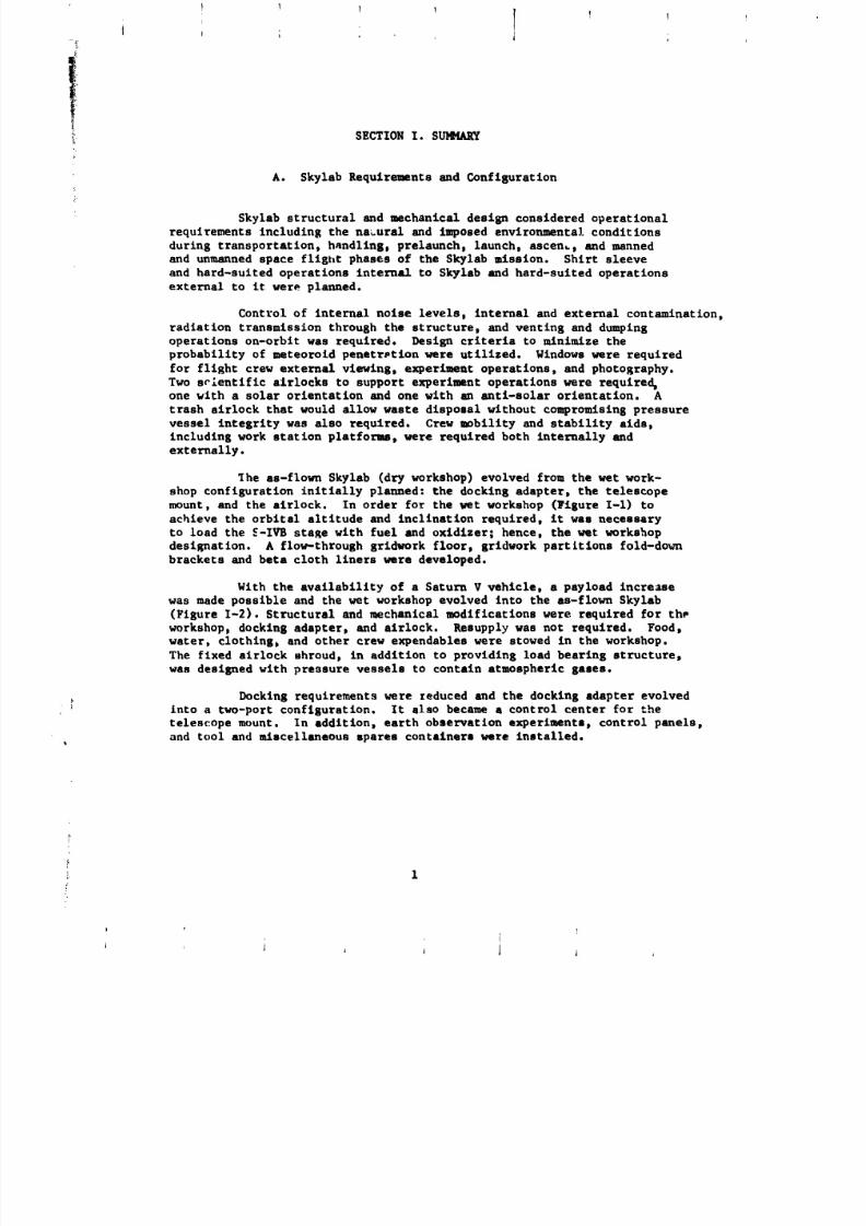
The as-flown Skylab (dry workshop) evolved from the wet work-
shop configuration initially planned: the docking adapters the telescope
mount, and the airlock. In order for the vet workshop (Figure I-1) to
achieve the orbital altitude and inclination required, it was necessary
to load the _-IVB stare with fuel and oxidizer; hence, the wet workshop
designation. A flow-through gridwork floors gridwork partitions fold-down
brackets and beta cloth liners were developed.
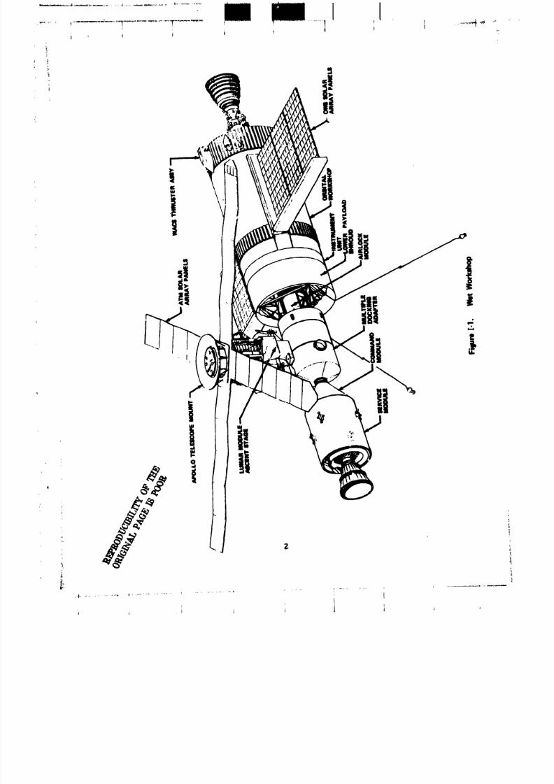
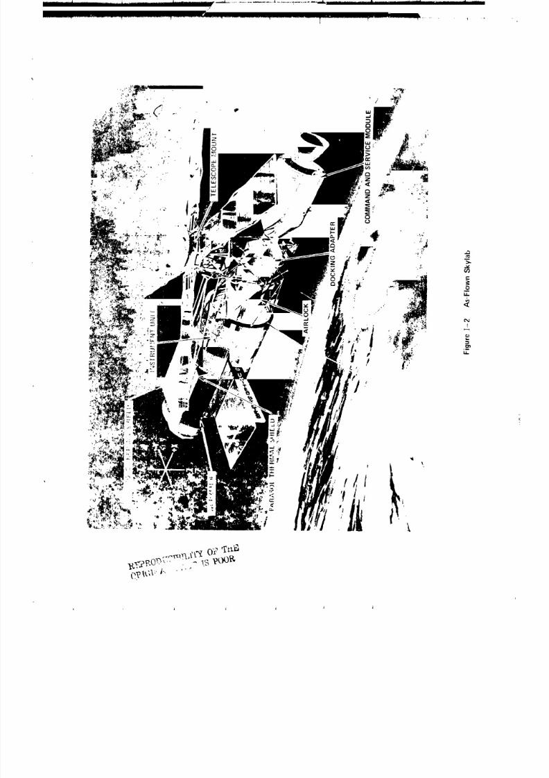
With the availability of a Saturn V vehicles a payload increase
was made possible and the wet workshop evolved into the as-flown Skylab
(Figure 1-2). Structural and mechanical modifications were required for the
workshop, docking adapters and airlock. Resupply was not required. Foods
water, clothings and other crew expendables were stowed in the workshop.
The fixed airlock shroud, in addition to providing load bearing structures
was designed with pressure vessels to contain atmospheric gases.
Docking requirements were reduced and the docking adapter evolved
Into a two-port configuration. It also became a control center for the
telesc:ope mount. In addition s earth observation experiments, control panelsp
and tool and miscellaneous spares containers were installed.
p 1
8/8/2019 MSFC Skylab Structures and Mechanical Systems Mission Evaluation
http://slidepdf.com/reader/full/msfc-skylab-structures-and-mechanical-systems-mission-evaluation 19/348
8/8/2019 MSFC Skylab Structures and Mechanical Systems Mission Evaluation
http://slidepdf.com/reader/full/msfc-skylab-structures-and-mechanical-systems-mission-evaluation 20/348
8/8/2019 MSFC Skylab Structures and Mechanical Systems Mission Evaluation
http://slidepdf.com/reader/full/msfc-skylab-structures-and-mechanical-systems-mission-evaluation 21/348
The payload shroud yes rec_eslped lonser, with increased
structural strength and improved capability, to attenuate sound pressure
for protection of the enclosed modules. The combined fixed airlock shroud
and payload shroud enclosed all Skylab hardware except the _trumenCation
unit and workshop from the time of stacking untll the payload shroud was
Jettisoned on orbit.
B. Structures and Hechanlcal Hardware Synopsis
The Skylab m:tsslon consisted of four launches: SL-J, the unmanned
Saturn Workshop launched by a Saturn V vehlcle; SL-2; SL-3; and SL-4,
three crews of three men launched by Saturn IB vehlcles. The first manned
phase was delayed because of loss of the workshop meteoroid shield, loss
of workshop solar array wing 2, and failure of workshop solar array win s
i to deploy. During the mission, other anomalies had smeller, but significant
impact relative to ground support by the structures/mechanlcal group
as well as other support groups, including such items as malfunctlonlnsrate gyros which required development of a stable platform for rate 8yro
six-pack installation; coolanol leakage which required development of
coolant reservlclng equipment; and sticking Cherm_ control valves which
required development of a heatlns kit for use in the suit coolin 8 water
loop.
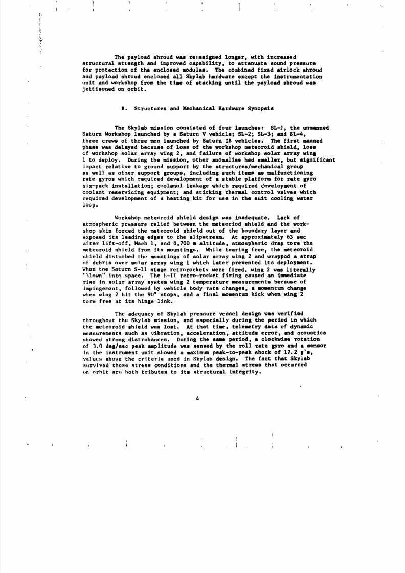
Workshop meteoroid shleld design was inadequate. Lack of
atmospheric pressure relief between the meteorlod shleld and the work-
shop skin forced the meteoroid shield out of the boundary layer and
exposed its leading edges co the slipstream. At approximately 63 sac
after lift-off, Math 1, and 8,700 m altitude, atmospheric drag tore the
meteoroid shleld from Its mountings. While tearing free, the meteoroid
shleld disturbed the mountings of solar array wing 2 and wrapped a strap
of debris over so]at array wing 1 which later prevented its deployment.
When the Saturn S-If stage retrorocket_ were fired, wing 2 was llterally"51o_n" into ._pace. The _'.-II retro-rocket firing caused an _Jmaedlate
rl.qe in solar array system wing 2 tenq_erature measurements because of
impingement, followed by vehicle body rate changes, a moment_un change
when wlng 2 hit the 90" stops, and a final momentum kick when wing 2
tore free at its hinge link.
The adequacy of Skylab pressure vessel deslsn was verified
throughout the SRylab mission, and especlally during the period in which
the meteoroid shield was lost. At that time, telemetry data of dynamic
measurements such as vibration, acceleration, attitude error, and acoustics
showed strong dlstrubances. Durln8 the same period, a clockwlse rots=ion
of 3.0 deg/sec peak amplitude was sensed by the roll rate Syro and a sensorin the instrument unit showed a maximum peak-to-peak shock of 17.2 8_s,
va]ut.._ above the criteria used in Skylab design. The fact that Skylab
survived these stress conditions and the thermal stress that occurred
on orbit at,. both tributes to its structural integrity.
4
It
i Ij _ , ++ J ++ J
8/8/2019 MSFC Skylab Structures and Mechanical Systems Mission Evaluation
http://slidepdf.com/reader/full/msfc-skylab-structures-and-mechanical-systems-mission-evaluation 22/348
t
; Various types of deployment mechanisms were used in Skylab design.
• Much of the hardware deployed or ejected had a _reater mass than similar
hardware used in other space programs and required designs with greater
structural strength and mechanical force to ensure deployment. No anomalieswere attributed to the deployment mechanisms. Although the adequacy ofG_chanisms used for workshop meteoroid shield and solar array deployment
cannot be totally evaluated, there were no indications that these designs
would not have performed as required had the meteoroid shield anomaly notoccurred.
Some of the doors exposed to the space environment exhibited problems
durin_ the Skylab mission. The S190 window cover was operated through
I00 trouble-free cycles and is recomaended for future applications.
Because of design redundancy and the capability of crewmen to
perform troubleshooting and in-flight maintenance, mechanical hardware
operation was adequate. Numerous fluid systems problems occurred, but these
were surmounted either by using redundant systems, modlfylng operatingprocedures, or by onboard maintenance. Leakage of fluids and probable
fl_lid system contamination caused a majority of mechanical hardware problems.
The etructures/mschanical area provided mission support at the
Huntsville Opezatlons Support Center throughout the Skylab mission for
action requests and mission action requests. A number of vorkarounds were
devised to support day-to-day activities aboard Skylab. Troubleshooting
procedures were developed for use on orbit, and tests using backup and
other hardware were performed, both at HSFC and at contactors' facilities.
The initial thermal shield installation on-orblt was a Jet-
developed parasol-type device deployed through the workshop solar scientific
airlock. During extravehicular activities, the second Skylab crew deployed
the NSFC developed tvln-pole thermal shield over the parasol. The initial
device was effective in reducing Skylab temperatures and the second achieved,
and allowed nmintenance of, internal temperatures at a nominal 72 "F except
for the high beta angle operations during the third manned phase.
Analyses of the initial Skylab pToblems, the conceiving, designingand materials selection, and the all-out hardware development, qualification.
packaging, development of deployment techniques and procedures (in
the MSFC neutral buoyancy simulator), and delivery efforts for the
thermal shields required only 10 days to complete. Evaluation of
these efforts and their products can be measured in ter_s of mission
success, for w_thout the thermal shields, the workshop would not have beenhabitable.
Simultaneously with thermal shield efforts, analyses, design,
selection, development, qualification, packaging, and delivery of solar
array release tools were accomplished. Techniques and procedures were
developed and verified in the neutral buoyancy simulator at NSFC.
Effectiveness of this ground support activity was verified when the first
flight crew successfully released workshop solar array wing 1. The tools
provided and the extravehicular activitilo accomplished by the crew
resulted in an increase of electrical power by about 50 portent.
5t
A A j
8/8/2019 MSFC Skylab Structures and Mechanical Systems Mission Evaluation
http://slidepdf.com/reader/full/msfc-skylab-structures-and-mechanical-systems-mission-evaluation 23/348
Malfunctioning rate gyros in _he telescope mount required that
a mounting location for installation _f additional rate gyros be selected
and that a stable platform for mounti_g them be developed t qualified,
and launched with the second Skylab _rew. The selected installation
locatlon was in the docking adapter between iongerons 4 and 5, immediatelyaft of cabin fan 2. The second Skylab crew mounted the platform and gyros
to brackets that had previously supported a storage container. Hounting
misalignments were well within tolerance, providing an evaluation of
ground support effectiveness, accuracy of drawings, and stable platform
development and test.
The slx operating gyros increased the noise level at thei_ location
beyond specified acoustic criteria in some frequency ranges, with the
greatest deviation beln_ 7 dB at 500 Hz. Overall sound pressure level
was required to be not greater than 72.5 dB, and this criterion was not
exceeded. The noise level caused no crew discomfort, but the atmosphere
circulation veloclty required for rate syro coolln_ caused minor annoyance
while crewmen worked at the telescope mount control and display panel.
Ground tests showed the desirability of two-fan gyro cooling
during the decreased pressure conditions when Skylab was unm_nlned, and
between the second and third manned mission phases. With the aid of a
universal camera mount and equipment straps, a portable fan from the work-
shop was attached to the telescope mount control and dlsp.ay foot _estralnt
and secured to preclude damage from docking loads.
Due to leakage the primary coolant loop had to be shut down during
the second manned phase. The leakage problem required design, development
and quallflcatlon of a coolanol reservlclng kit that was launched with
and used by the third Skylab crew. Penetration into the coolanol system
was made with a saddle valve developed by NASA. After the crew reservlced
the primary loop with 7.7 Ib of coolanol, full capability of the systemwas restored. Secondary coolant loop reservlclng was not required.
The alrlock 47 QF thermal control valves "B" in each coolant
loop stuck during the first Skylab extravehlcular activity. A heater and
a_soclated equlpment were designed and flown up with the second Skylab
rrew to add heat to the system in 250 W increments, up to 1,000 W,
_hould _he thermal control valves again move to and remain in a colder
than desirable fl()w _osltlon. Although the heater was launched with
the _econd $kylab crew_ it was never used since the system performed
adequately through the remainder of the Skyl_b mission.
6
8/8/2019 MSFC Skylab Structures and Mechanical Systems Mission Evaluation
http://slidepdf.com/reader/full/msfc-skylab-structures-and-mechanical-systems-mission-evaluation 24/348
I 1 1 ! I l v
_. SECTION II. INTRODUCTION
i A. Purpose
The purpose of this report is to provide a structural integ_ity
and me.chanicl systeuus and component performance evaluation of the
! Saturn Workshop hardware for the Skylab mission, including prelaunch.The evaluation provides discipline oriented insight into normal hardware
i performance as well as anomalous performance. Evaluations are based onflight data, test data, crew reports, and photographs. It is intended
! that the report will becon_e a permanent record of hardware performance
and base from whlch future spacecraft structures and mechanical
systems will be developed.
• B. Scope
i Evaluation is made for each Saturn Workshop module and the
pertinent equipment and systems therein. Anomalies are discussed with-
in the appropriate e_aluation section.
The following objectives were primery in the preparation of
this performance evaluation report:
1. Identification of the requirements and configurations ap-
plicable to the structural and_chanical items evaluation of the
Saturn Workshop modules.
2. Recordin S of the criteria and/or parameters which accuratelyand completely evaluate/demonstrate that the mechanical and structural
capabilities of the specific items under the cognisance of the
. Structures ar.d Mechanical Mission _upport Croup were, or were not,
• within the requirements specified.
3. Providing constructuve recounendations relative to hard-
ware application for future projects based on assessment of the per-
formance of the Saturn Workshop modules.
|
I
8/8/2019 MSFC Skylab Structures and Mechanical Systems Mission Evaluation
http://slidepdf.com/reader/full/msfc-skylab-structures-and-mechanical-systems-mission-evaluation 25/348
! 1 I I I !
SECTION III. APPLICABLE DOCUM_TS*
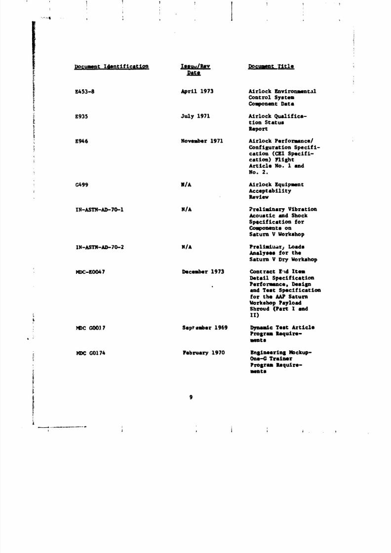
Docu,._ent Identification Iss, t.e/Rev Document Title
CP003MO0023 March 1969 Part I End Item Detail
Specification _Prime
Equipment) Performance
and Desisn Require-
monte, E1003023,
Saturn Payload Shroudfor the Saturn I
Workshop and Apollo
Telescope MountMissions
CPl14AlO00026 N/A MD£ Contract End Item
,CEI Specification
CP2OSOJ1C November 1969 Contract End Item
Detail Specification
(Prime Equipment),
Performance/Desisn
Require_nt8
DAC-56618A September 1969 Quality Prosram Plan
DAC-56620C May 1971 Acoustic Shock andVibration Test
Criteria
DAC-56689A January 1970 Confisuratlon Man-
agement Plan
DAC-56697A September 1969 Test Plan
DAC-5660IA September 1969 Reliability FroStSPlan
DAC-5672A September 1969 Govermmnt Furnished
Property Requiremmt8
ED-2002-1209-9 Ausust 1973 Skylab Interior Acoustic
Environment Report
E451-5102 March 1974 AM Coolant Systes
Packese
*Many of these publ£cet£ons are revised periodically. The latest edJ.tiqnshould be consulted.
8
i i
8/8/2019 MSFC Skylab Structures and Mechanical Systems Mission Evaluation
http://slidepdf.com/reader/full/msfc-skylab-structures-and-mechanical-systems-mission-evaluation 26/348
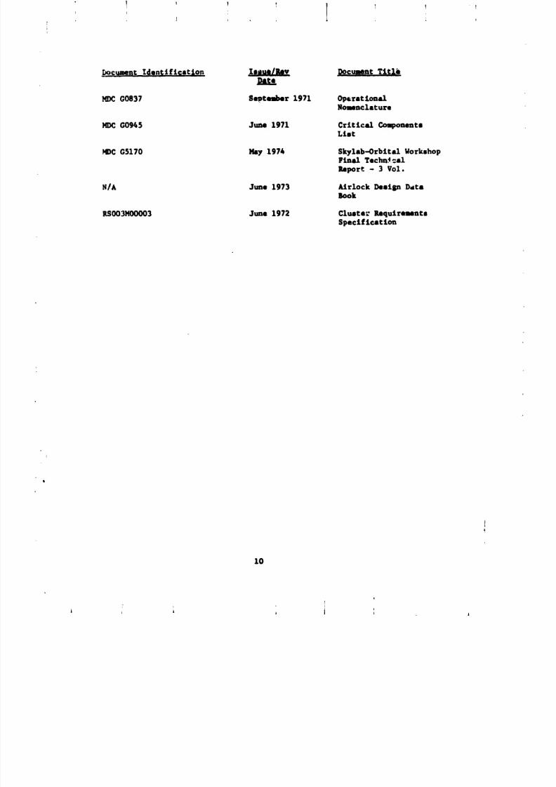
Do_ummptIdent ifteatlon Issu_IRev _mm_.'r_t Ze
!I vA53-8 April 1973 ALrlock Envlronnant.Ll
ControZ System__ ComponemtData
E935 July 1971 ALrlock Qualifica-
tion Stature
i eeportE%6 November 1971 Atrlock Performance/
.. Conflgurat ion SpecLfi-
.- cation (CEZ SpecLfi-
-_ cation) YlLEhtArticle No. I andNO. 2.
G499 N/A ALrlock Equipment
AcceptabilityRevtev
IN-ASTN-AD-70-1 N/A Preliminary VibrationAcoustic and Shock
Specification forCo_ommt s on
Saturn V Workshop
IN-ASTN-AD-70-2 N/A PrelLmL_r: LoadsAnalyses for the
Saturn V Dry Workshop
KDC-EO047 December 1973 Contract E,_d Item
Detail Specification, Performance. Destan
and Test Specificationfor the AKP Saturn
Workshop PayloadShroud (Part I andII)
* _ GO0].7 Seprtuber 1969 Dynm_Lc Test Article
_ Prosran Require-merits
_ G0174 February 1970 I_nsinearin8 Nockup-One-G Trainer
Prosran Itmqulrn-Imnts
8/8/2019 MSFC Skylab Structures and Mechanical Systems Mission Evaluation
http://slidepdf.com/reader/full/msfc-skylab-structures-and-mechanical-systems-mission-evaluation 27/348
.Document Identification _ Docunent TttXb
_C G0837 September 1971 OpcrstlonalNomencXature
_C G0945 June 1971 Critical CouponentsLint
MDCG5170 Nay 197h Skylab-Orbital WorkshopFinal Techn4 _al
Report - 3 Vol.
S/A June 1973 _trlock Desisn Databok
RS003HO0003 June 1972 Cluete_ Requirenent8
Specification
10
t
A , i , t i ,
8/8/2019 MSFC Skylab Structures and Mechanical Systems Mission Evaluation
http://slidepdf.com/reader/full/msfc-skylab-structures-and-mechanical-systems-mission-evaluation 28/348
I I I
;r
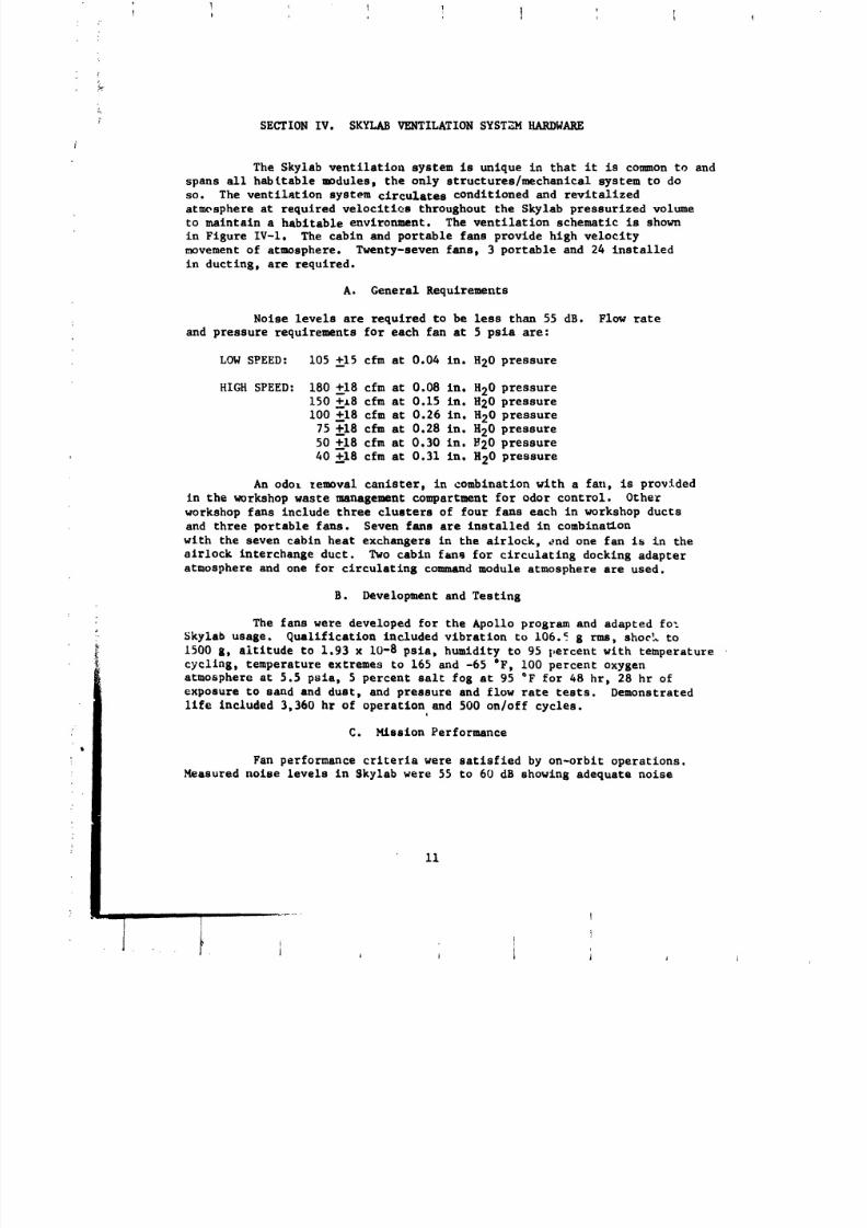
SECTION IV. SKYLAB VENTILATION SYSTZM HARDWARE
The Skylab ventilation system is unique in that it is common to and
spans all hab(table modules, the only structures/mechanical system to doso. The ventilation system circulates conditioned and revitalized
atmosphere at required veloclti_s throughout the Skylab pressurized volume
to maintain a habitable environment. The ventilation schematic is shown
in Figure IV-I. The cabin and portable fans provide high velocity
movement of atmosphere. Twenty-seven fansp 3 portable and 24 installed
in ductlng, are required.
A. General Requirements
Noise levels are required to be less than 55 dB. Flow rate
and pressure requirements for each fan at 5 psia are:
LOW SPEED: 105 +--15cfm at 0.04 in. H20 pressure
HIGH SPEED: 180 +--18cfm at 0.08 in. H20 pressure
150 +._8 cfm at 0.15 in. H20 pressure
i00 +--18cfm at 0.26 in. H20 pressure
75 +-18 cfm at 0.28 in. H20 pressure
50 +_18 cfm at 0.30 in. _20 pressure
40 +_18 cfm at 0.31 in. H20 pressure
An odor temoval canister, in combination with a fan, is provided
in the workshop waste management compartment for odor control. Othe_
workshop fans include three clusters of four fans each in workshop ducts
and three portable fans. Seven fans are installed in comblna_on
with the seven cabin heat exchangers in the airlock, and one fan is in the
alrlock interchange duct. Two cabin fans for circulatlng docking adapteratmosphere and one for circulating command module atmosphere are used.
B. Development and Testing
The fans were developed for the Apollo program and adapted fo_
5kylab usage. _ualiflcatlon included vibration to 106.5 g rms, shoeL to
1500 gt altitude to 1.93 x 10⁻⁸ psia, humidity to 95 |,ercent with temperature
cycling t temperature extremes to 165 and -65 °F, i00 percent oxygen
atmosphere at 5.5 pslaj 5 percent salt fog at 95 "F for 48 hr_ 28 hr of
exposure to sand and dust, and pressure and flow rate tests. Demonstrated
life included 3,360 hr of operation and 500 on/off cycles.4
C. Mission Performance
Fan performance criteria were satisfied by on-orbit operations.
Measured noise levels in Skylab were 55 to 60 dB showing adequate noise
11
i i i ....... i I]" "" ' J , J 1 i J j
8/8/2019 MSFC Skylab Structures and Mechanical Systems Mission Evaluation
http://slidepdf.com/reader/full/msfc-skylab-structures-and-mechanical-systems-mission-evaluation 29/348
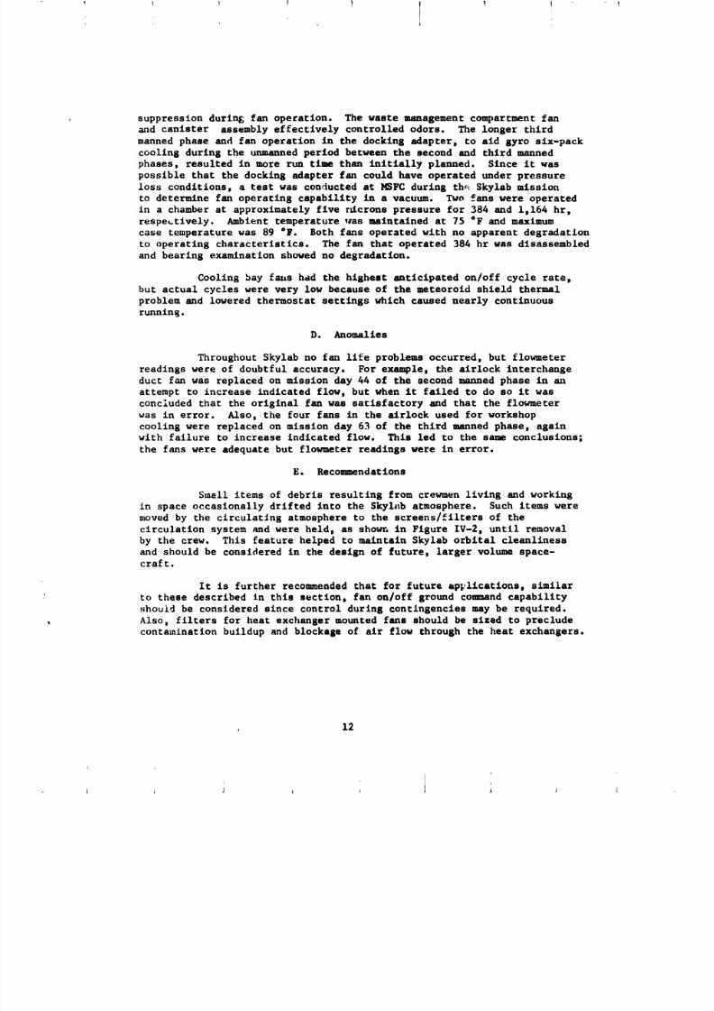
, suppression during; fan operation. The waste management compartment fan
and canister assembly effectively controlled odors. The longer third
manned phase and fan operation in the docking adapter, to aid gyro six-pack
cooling during the unmanned period between the second and third manned
phases, resulted in more run time than initially planned. Since it was
possible that the docking adapter fan could have operated under pressure
loss conditions, a test was conducted at HSFC during the Skylab mission
to determine fan operating capability in a vacuum. Two fans were operated
in a chamber st approximately five r_crons pressure for 384 and 1,164 hr,
respectively. Ambient temperature was maintained at 75 °F and maximum
case temperature was 89 °F. Both fans operated with no apparent degradation
to operating characteristics. The fan that operated 384 hr was disassembled
and bearing examination showed no degradation.
Cooling bay f_is had the highest anticipated on/off cycle rate,
but actual cycles were very low because of the meteoroid shield thermal
problem and lowered thermostat settings which caused nearly continuous
rtmnin_.
D. Anomalies
Throughout Skylab no fan life problems occurred, but flowmeter
readings were of doubtful accuracy. For example, the airlock interchange
duct fan was replaced on mission day 44 of the second manned phase in an
attempt to increase indicated flow, but when it failed to do so it was
concluded that the original fan was satisfactory and that the flowmeter
was in error. Also, the four fans in the atrlock used for workshop
cooling were replaced on mission day 63 of the third manned phase, againwith failure to increase indicated flow. This led to the same conclusions;
the fans were adequate but flowmeter readings were in error.
E. Recommendations
Smell items of debris resulting from crewmen living and working
in space occasionally drifted into the Skyl_ atmosphere. Such items were
moved by the circulating atmosphere to the screens/filters of the
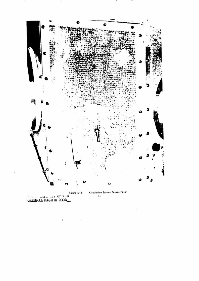
circulation system and were held, as showr,in Figure IV-2, until removal
by the crew. This feature helped to maintain Skylab orbital cleanliness
and should be considered in the design of future, larger volume space-craft.
It is further recomaended that for future apFlications, similar
to these described in this section, fan on/off ground comnand capabilityshould be considered since control during contingencies may be required.
Also, filters for heat exchanger mounted fans should be sized to preclude
contamination buildup and blockage of air flow through the heat exchangers.
12

8/8/2019 MSFC Skylab Structures and Mechanical Systems Mission Evaluation
http://slidepdf.com/reader/full/msfc-skylab-structures-and-mechanical-systems-mission-evaluation 30/348i
8/8/2019 MSFC Skylab Structures and Mechanical Systems Mission Evaluation
http://slidepdf.com/reader/full/msfc-skylab-structures-and-mechanical-systems-mission-evaluation 31/348
q | .....
Figure IV 2. C=rculationSystemScreen/Filter

8/8/2019 MSFC Skylab Structures and Mechanical Systems Mission Evaluation
http://slidepdf.com/reader/full/msfc-skylab-structures-and-mechanical-systems-mission-evaluation 32/348
SECTION V. SKYLAB NODULES AND HARDWARE
All the major Skylab modules and hardware items related specifically
to module structural/mechanical performance are evaluated in this section.
A. Airlock
1. Basic Requirements and Configuration Evolution. The alrlock
provides: a habitable, interconnecting pressure vessel between the
docking adapter and the workshop; the atmospheric nitrogen supply;
support for intervehicular activities; an airlock to support extravehicular
activities. The as-flown airlock (Figure VA-I) is an item that was carried
over from the wet workshop to the dry workshop. At the time of carry
over, one of the four alrloek trusses had a removable link; two others
were modified to this configuration _o allow mounting of six nitrogen
bottles on the three removable link trusses. The docking adapterinterface ring was strengthened and gussets were added to the structural
transition section stringers. Other modifications such as penetrations,
welds, and revised rivet patterns were also accomplished.
2. Structures. Coumensurate with design requirements and
criteria, the airlock pressure vessel consists of a structural trmlsition
section, a tunnel section, or lock compartment, and a flexible tunnel
extension or bellows. It structurally supports the docking adapter,
accepting its loads at the interface ring and transmitting them and its
own to the fixed airlock shroud by way of four fusion-welded, aluminum
tubing truss assemblies. Sealant was applied to the interface rings
to maintain internal pressure. The bellows provide a flexible pressure
vessel interface to the workshop.
the structural transition section volume is 288 ft 3 contained
in a welded aluminum, stressed-skin, semimonocoque cylinder 47-in. long
and 120 in. in diameter. It reduces to 65 in. at the tunnel section.
The stingers and longerons resistance welded externally to the skin,
carry overall axial loads and body bending loads with intermediate
internal rings added for support. Loads are transferred to truss fittings
by way of eight intercostals.
The tunnel section is a semimonocoque, aluminum cylinder 65 in.
in diameter, divided by two internal bulkheads with mating pressure
hatches. The 31-1n. lorg forward compartment interfaces with the
structural transition ,,ectlon, the 80-in. long center tunnel (lock)
compartment interfaces with the bellows and an octagonal airlock
ring. Seven external shear webs and the octagonal ring provide
attachment and shear continuity between the tunnel section and the
trusses.
Accommodation of deflection with minimum load transfer between
the air]ock and workshop is provided by the 42.5-in. diam, 13-in.
I L
8/8/2019 MSFC Skylab Structures and Mechanical Systems Mission Evaluation
http://slidepdf.com/reader/full/msfc-skylab-structures-and-mechanical-systems-mission-evaluation 33/348
.......... _.........................................................' " "I I !
8/8/2019 MSFC Skylab Structures and Mechanical Systems Mission Evaluation
http://slidepdf.com/reader/full/msfc-skylab-structures-and-mechanical-systems-mission-evaluation 34/348
r
!.
_q
long convolute, flexible bellows, Internal fluorocarbon coating provides
a redundant bellows seal and a fiber glass laminate cylinder inside the
bellows protects it from damage.
a. Pressure vessel. The required airlock relief valve
upper limit pressure is 6.2 psia. While under static loads, the flight-
type wet workshop configuration static test article was proof pressure
tested to 1.4 times the limit pressure. Burst pressure tests were also
conducted on th_ _rticle to 2.0 times limit pressure with no external
loads applied. A proof pressure test to 1.4 tires the limit load was
conducted on the flight article with no external loads _pplied.
b. Bending moment and axial loads. The airlock specification
weight was 15,416 ib and design requirements stipulated that it be able
to support a docking adapter weight of 14,000 lb. Lift-off weights for
the two modules were 15,166 _,d 13,645 Ib, respectively. The structurewas designed for exposure to specified thermal, acceleration, shock, random
vibration, pressure, and acoustic environments. The minimum required
factor of safety on limit loads combined with limit operating pressurefor the alrlock structure is 1.25 for unmanned conditions and 1.36
for manned conditions, cou_nensurate with criteria imposed for tested
structure. Nitrogen bottle support structures, excluding trusses, are
designed to a factor of safety of 2.0 (unmanned condition) to precludethe need for static test.
The airlock static test article, a production type
structure, was tested at the MSFC static test facility.
3. Natural Environments Design. Airlock requirements for
maintaining habitable volume in the space environment, includlng radiatiovprotection, are provided by structural design. Appropriate protection
against particulate matter, excessive h_unidity, rain, ground winds and
flight winds are primarily a function el the payload shroud, the fixed
airlock shroud, and the KSC facility, including facility gasses. The
meteoroid protection requirement for the airlock provided for the
_tructural transition section by the radiator and for the remainder
of the airlock, and the instrumentation unit and workshop dome, by the
fixed airlock shroud and meteoroid curtains. These flexible curtains,
made primarll7 of Viton ruhber impregnated fiber glass, have gold-coated
interiors and off-white fiber glass exteriors. They are stretched conically
hetween the structural transition section and the fixed airlock shroud
except for the extravehicular activity bay quadrant. Here, the tunnel
_ectlon is protected by two curtains stretched from shear webs to exterior
truss members, and the workshop dome is protected by a curt;_i,stretched
between the airlock octagonal bulkhead and the fixed airlock _hr_ud lower
intermediate ring. Curtains are also stretched fore and aft of the airlock
hatch, fastening to the structural transition section and the octagonal
bulkhead. The airlock hatch is protected by a rigid fiber glass installation.
No occurrence of meteorlod penetratlon was detected during the Skylabmisslon.
17
fI
i
8/8/2019 MSFC Skylab Structures and Mechanical Systems Mission Evaluation
http://slidepdf.com/reader/full/msfc-skylab-structures-and-mechanical-systems-mission-evaluation 35/348
Requirements to distribute breathable atmosphere level
during operations at KSC and to permit purging of the airlock
and docking adapter during prelaunch are provided by the aft compartmentpurge fitting. Venting at KSC during ascent and on-orblt was a function
of the docking a_.apter. Prelaunch atmosphere and purge flow was
successfully provided by a "drag-on" hose at KSC.
Structural design li_Lts internal radiation to 0.6 tad/day.
On-orbit radictlon measurements taken in the airlock show the average
internal radiation to be approximately 0.I0 tad/day, which is well
within the design requirements.
4. Mechanical Components.
a. Hatches. An extravehicular activity hatch and two
internal hatches were required for the _Lrlock tunnel section. Specifications
state that all three hatches have a window and that they be capableof being restrained in the open position.
(1) Extravehicular Activity Hatch. This pressure
hatch was required to provide astronaut access to the exterior of the
vehicle. Operation of the opening mechanism by a pressure suited crewman
from the inside by applying a meximum force of 45 lb was a design
requirement. The single stroke hatch handle is equipped with a positive
lock for holding it in the closed position. Following closeout at the
pad, exit was through the extravehicular hatch. The handle lock could not
then be engaged; the first crew engaged the lock during activation. There-
after, each usage required lock release prior to moving the handle through
a 153 ° arc to actuate the 12 latch assemblLes for opening or closing.
After each closing the handle lock is reensased. A catch la_ch, incorporated
to restrain the hatch slightly open, is provided to prevent complete
opening until pressure equalization.
The extravehicular activity hatch was partially
qualified by similarity to the Gemini hatch. Additional Skylab test
requirements consisted of meteoroid impact simulation, handle force testst
and retest of the h_tch sea&. Also, the static test article hatch was
installed during testing at HSFC when the airlock was pressurized to
12.4 psig, and during the vibroacou_;._ test at JSC. During these testsno problems were attributed to the hatch.
Planned hatch operations during the Skylab program
were 50 cycles on the ground and 6 cycles on orbit. The hatch was
actually used on-orbit eight times. During the first crew debriefingit was state_ that forces and hatch operation were essentially the sane
as on the trainers and that hatch size was t_equate for all equipmentant personnel transfers.
18
8/8/2019 MSFC Skylab Structures and Mechanical Systems Mission Evaluation
http://slidepdf.com/reader/full/msfc-skylab-structures-and-mechanical-systems-mission-evaluation 36/348
8/8/2019 MSFC Skylab Structures and Mechanical Systems Mission Evaluation
http://slidepdf.com/reader/full/msfc-skylab-structures-and-mechanical-systems-mission-evaluation 37/348
I
_round testing included temperatures at 20, 120,
and 160 °F; proof pressure at 8.7 pslg; altitude at 9.3 x i0-7 psla;
leakage at the rate of 190 scum; and 507 hatch and _achanlsm cycles,Lncluding high, low and ambient temperature at ambient pressure, an, l
24 cycles at 9.3 x 10⁻⁷ psia. Hatch seals were qualified concurre:,tly
with the extravehicular activity hatch seal since they were baelcally
alike. Anticipated on-orblt usage was nine open/close cycles for the
forward hatch and three cycles for the aft hatch. The forward hatch
was opened nine times and closed eight. The aft hatch, once opened,
was restrained in the open position throughout the remainder of the Skylab
mission. Internal hatch operations presented no problems. Crewmen reported
that the hatches were adequate in size and easier to nmnage in zero g
than they had been in the trainers.
b. Pressure equalization valves. Three identical valves
are used in the airlock: one in each internal hatch plus the Icck compart-
ment vent valve, mounted on the tunnel wall adjacent to the extravehicular
activity hatch. With air at 70 _20"F and inlet pressure of 5.0 psia,
flow was required to be i0.0 Ib/uLtn with valve outlet pressure of 2.6 psla
maximum. Maxlmum torque for valve handle operation was requlred to be
40 in.-ib with a pressure of 6.2 psld.
A disc in each butterfly-type valve can be actuated from
either side by a handle and shaft arrangement that is coupled to the
valve shaft by bevel gears. The disc is offset from the valve sha£t around
which it rotates for opening and closing. When open, effective flow area
is 1.44 in 2. The valve is held either fully open or fully closed
by ball type detents that lock the handle shaft. Detente are unlocked
by pressing a button on either handle. If the valve is left in a partially
open position, it is spring-loaded to close which allows engagement ofthe detent. Valve length overall is 9.63 in. and the mounting flange
is approxlmately 63 _n. in diameter.
Internal hatch pressure equalization valves were required
to be open at launch to allow tunnel venting through the closed hatches
during ascent. During extravehicular activities preparation, the workshopdome hatch and the forward alrlock internal hatch and valve were closed
before manually operating the lock compartment vent valve to depressurlze
the lock. Complete venting of the lock compartmnt from the noalnal
5.0 psia to external ambient was precluded by gas exhausting from crew suits
such that the compartment retained pressure of about 0.15 psla until the
extravehicular activity hatch was opened. Ground testing included proof
pressure to 12.4 pslg, burst pressure to 24.8 pslg, twsnty-elght 24-hr temperature/
humidity cycles, pressure/temperature testS, ieak tests not to exceed0.19 scc/m gaseous nitrogen at 6.2 psig. 500 operating cycles at 5.0 psia
outlet pressures, natural envlronnmnts, strength and shock talts,
cold soak, and random vibration to I0 g rm overall. The valves were also
tested with the airlock structure during static testing at NSFC andvlbroacoustic tests at JSC.
2O
8/8/2019 MSFC Skylab Structures and Mechanical Systems Mission Evaluation
http://slidepdf.com/reader/full/msfc-skylab-structures-and-mechanical-systems-mission-evaluation 38/348
1 t ? ? 1 T 1
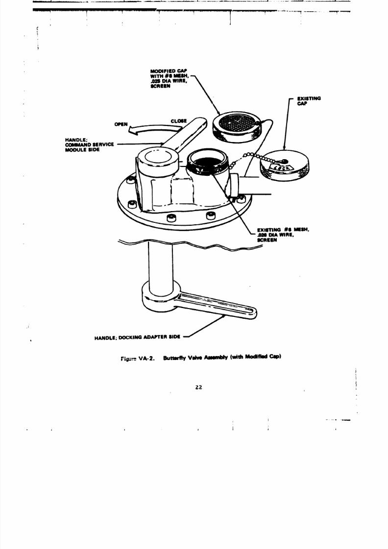
It was estimated that 25 total valve cycles _,ould be required
on-orblt. The forward hatch pressure equalization valve and the alrlock
vent valve were each cycled elsht times. Neither valve malfunctioned,
but the alrlock vent valve accumulated ice on the inlet screen and thus
restricted 8as flow during depressurlzatlon. A 0.025-In. dlmeter,
304 stainless wire, #8 mesh screen was assembled to a valve cap and flown
on-orbit by the second manned crew for use on the airlock vent valve durin8
subsequent depressurizatlon activities (Figure VA-2). This screen reduced
the 8as flow restriction; ice crystals formed in the central screen : _a,
only, leavin$ the outer portion free of ice to allow atmospheric flo_.
When pressure decreased to about 1 psi, the screened cap was removed
to achieve an increased atmospheric flow rate through the existin$#_ m_sh screen in the vent waives.
c, Windows and Covers. Seven windows were required for the
airlock. In addition to the windows in the three hatches, four
8 by 12-in, oval windows were required to be spaced at 90* intervals,37"52' off the vehicle axes, around the aft portion of the structural
transition section. Provisions to cover and uncover these windows
with a thermal barrier were required. Optical qualities were
requlred to be compatible for use by the crew during visual observations.
All seven windows were required to be double pane and the five windows
designed for external viewing were required to have valves for venting
the space between windows panes. These valves were opened at vehiclefinal closeout at _SC to allow venting of the dry argon gas between
the panes durin_ vehicle ascent, and were closed by the first aanned crew
during activa':ion to preclude "breathin$" caused by internal vehicle
pressure fluctuations.
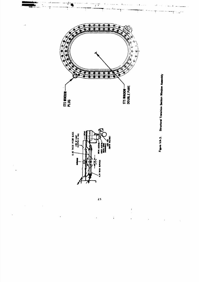
The structural transition section windows, shown in Figure VA-3,
are protected externally by sliding, fiber glass-reinforced, plastic-laminate covers operated by an internal crank assembly which is locked
(open or closed) by a quick-release pin. Each exterior window pane is
0.42-in. thick vycor glass and its internal surface has a thin gold coating
to reflect infrared light to reduce heating of the inner pane, thereby
avoiding a touch temperature problem. Each interior pane is 0.24-in.
thick tempered glass with its external suzface having an ultraviolet
reflective coating to avoid ultraviolet trigRering of the caution
and warning fire alarm. The nominal space between panes is 0.25 in.
The panes are individually sealed to preclude atmospheric leakage. Limit
pressure is in the compartment and 14.7 psid trapped between
panes.
A fracture _chanlcs analysis was conducted on the vlndows.
A sympathetic shatter test demonstrated that the outer pane remainedintact and maintained pressure up to 25 psid even though the inner pane
was purposely broken by impact. Burst pressure tests were conducted in
fixture duplicating actual installation. The inner pane _pace was
pressurized to rupture. All burst tests indicate failure at approximately
65 psid. No gog_in_ of the windows occurred during a_lent or low
21
A
8/8/2019 MSFC Skylab Structures and Mechanical Systems Mission Evaluation
http://slidepdf.com/reader/full/msfc-skylab-structures-and-mechanical-systems-mission-evaluation 39/348
_............. ! ......................_.......... _ ........... ! ................. T................. _,.........................x.................._---"
]r
HANDLE;COMMANDSERVICEMODULE SIDE
EXISTING#S MESH,AS8DIAWIRE,
HANDLE;DOCKINGADAPTERSIDE
t_tgu_VA-2. Buttarfly Vdve A4mmblly(wishModified Cop)
zz
8/8/2019 MSFC Skylab Structures and Mechanical Systems Mission Evaluation
http://slidepdf.com/reader/full/msfc-skylab-structures-and-mechanical-systems-mission-evaluation 40/348
" ' * ...... ..........................._............. _ ...................... v..........................................
_3
h
8/8/2019 MSFC Skylab Structures and Mechanical Systems Mission Evaluation
http://slidepdf.com/reader/full/msfc-skylab-structures-and-mechanical-systems-mission-evaluation 41/348
I dl_ ,...Lr.,..h ...........
q ........ _" ..................... _ ............... 1 _ _
1 'f I | I I I
temperature follin8 tests. Maps of each window were prepared showin&the location and size of all _croscratches and leaks. Protective
covers were then installed over the inner panes end ,*he outsideprotective covers closed. These covers were renoved and the mmppini
rechecked at KSC Just _=ior to flnal closeout. O_ly one ne_ mmall
scratch wee discovered and none of the others ha_ snlerled, so the windows
were considered 8atlsfactory for leunch.
Additional window assenbly quallflcatlon tests included
launch vibration with leakale naasured before and after vibration, leakale
at -30 "F., proof pressure at 8.4 psll, and Internal cabin burst pressure
to 12.4 p8£s. Cover assembly qu&_tflcation Inc11_ded random vibration
st 6.8 _, leek test of cover drive assenbly, and 300 operatln8 cycletJ at
9.49 x 10⁻⁴ corr. Each flisht window pane w88 proof-loaded at acceptance
to 30 psis, and sll window assemblies were proof tested to 8.4 psisinstalled in the module.
Window size and shape are adequate for on-orblt use according
to crew comments during debrieflni, althoush interference from exterior
structure Frecluded some photosrcphlc useSe. Window £o8sin8 on the earthside of the vehicle occurred after 3 to 4 hr exposure with covers
open. 8o fossin8 was observed in window assemblies on the sun side
of the vehicle. When e_rth side covers _tre closed, windows would free
themselves of foe in 2 to 3 hr.
Window covers were closed durlns sleep perlo_, to decrease
the lilht level in the workshop sleep com_ertnent. Window cover mechanisms
became Increaslnily harder to operate as the mission pro|zoomed with
the #3 cover mschanlsm 5e!.n8 the most difficult to operatp.
The extravehicular activity hatch window is identical to the
hatch windows used in the Oe_tnl prosrau except for the ultraviolet
infrared coetinis and the addition of s trapped volume vent valve.
The outer pane is 0.380-in. Vyc:or and the inner pane is 6.220-£n.
ten_pered Blase _ith a 0.250 special between the two. The 8round verification
of the hatch tr£miow paralleled that for the struct,,rsl transition sectionwindows.
The extravehxcular activity hatch _aindov waJ not used. A
stowed cover was Installed over the window by the first Skylsb crew
and was not removed throushout the three manned mission phases.
The 8.5-1n.-dima interior hatch wJ.ndows ere covered
by a protectlve mesh on either side. The window on the forward hatchwas used by the third crewman for vlew_n 8 the two extrevehicular crewmen
in tho lock compartment of the struct,ral transition section durini
extravehicular activities. Size was considered adequate _nd £nstellet_on
necessery to support extravehicular operations. Ths_e windows had no
cavity bleed valve and allowed no sisns of foIsin I.
24

8/8/2019 MSFC Skylab Structures and Mechanical Systems Mission Evaluation
http://slidepdf.com/reader/full/msfc-skylab-structures-and-mechanical-systems-mission-evaluation 42/348
I ] ! I I
f
The most likely cause of condensation that formed on the
interior surface of earth-side s_ructural transition section exterior
window panes is the breathing of humidity laden atmosphere through the
cavity vent valves caused by minor vehicle pressure fluctuations and thermal
cycling of the window structure. Initial design of the windows providedlockup of 14.7 psia dry argon in the cavity. A later modification
provided pressure bleeding. Had initial design been followed, the probability
of condensation would have been decreased. Future design should consider
alternatives such as: dry gas lockup; partial cavity _ieeding such that
lockup pressure would be about 6.0 psld at lowest internal pressure
(0.5 psia) and about 1.5 psid at nominal operating range (5.0 psia);
window heaters; cr periodic dry gas purging.
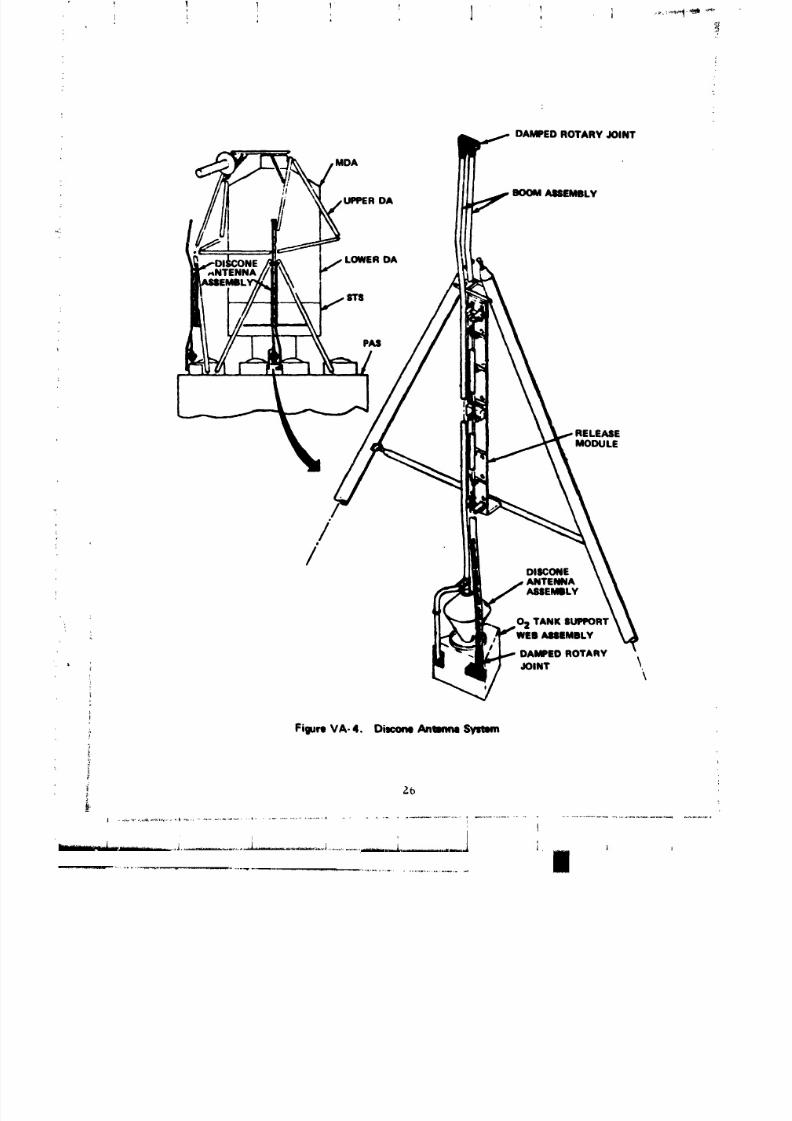
d. Discone Antennas. Two discone antennas are mounted on
the fixed airlock shroud for telemetry transmisslon and command reception
(Figure VA-4). Since the deployed telescope mount and solar arrays
have a degrading effect on radiation patterns, the antennas are mounted
on folding booms to deploy the discones away from the cluster. The boomsfold in two segments for stowage inside the payload shroud for
launch ann ascent, aQd are released on ground command through the
alrlock digital command system after the shroud is Jettisoned. The
primary release logic is powered from alrlock power bus #I to release
both antennas. A redundant system was powered from bus #2 and triggered
by a backup command. An alternate method of deploying the antennas was
available to the crew onboard. The deployment mechanism has two spring
powered rotary Joints which supply energy for boom extension, control
the rate of deployment, and lock the boom in the extended position. After
full deployment, a locking pin triped a microswitch which transmited a
signal to verify full boom extension. One rotary Joint connects the two
boom segments together and rotated through approximately 180" while
the other mounts the boom assembly to the upper ring of the fixed
airlock shroud and rotated through approximately 90 ° .
Ground verification tests were conducted on the rotary
joints, release actuator, release module assembly, and the deployment assembly.
Test environments for these components were vibration, life, humidity,
temperature, acceleration, and functional. After the humidity quslification
test, the rotary joints failed to operate because of corrosxon. This condition
was caused by a stainless steel roll pin pressed through an aluminum
bearing bushing and left unprotected from the exposed environment.
Corrosion was also evident on the internal shaft where the nickel
plating separated from the aluminum shaft because of poor adheslo_
on the sharp corners. The solution was to have the rotary Joint sharp
edges rounded and replated. The music wire springs were replaced with
stainless steel springs. The stainless steel roll pin was pressed half-wayinto the bearing bushing and sealed on the back side. After rework was
completed, the unit was succ_ssfully retested. System performance
was verified when a complete deployment assembly was functionally tested
to measure time to deploy and rates, using air bearings to support the
weight of discone and booms.
25
8/8/2019 MSFC Skylab Structures and Mechanical Systems Mission Evaluation
http://slidepdf.com/reader/full/msfc-skylab-structures-and-mechanical-systems-mission-evaluation 43/348
! I _ 1' ,
DAMPED ROTARY JOINT
BOOM AMEMBLY
f
LOWER OA
,_NTENNA
PAS
RELEASE
MODULE
//
DISCONE
ANTENNAASSEMILY
02 TANK $UPPOR1
WEB AUIMBLY
DAMPED ROTARY
JOINT \\
,, FigureVA-4. DimcmeAntmmeSymmm
_L
t' , i |
..................................... ,]
8/8/2019 MSFC Skylab Structures and Mechanical Systems Mission Evaluation
http://slidepdf.com/reader/full/msfc-skylab-structures-and-mechanical-systems-mission-evaluation 44/348
I
k
£
_ The JSC vibroacoustic test article incorporated a production
release module, production booms with d,,-_y rotary Joints, and a mass
: simulation of the antenna. No problems or anomalies were encountered.
The flight booms were subjected to a full deployment functional test atthe manufacturer's facility using the air bearing test setup at final
acceptance. A trial release of the final installation was performed at
KSC to assure free movement and availability of deployment torque, but
full deployment was not feasible in that configuration. A problem
developed at KSC when it was discovered that the nylon webbing, which
restrains the booms in the stowed position, stretched under the rigging
tension. This stretching could allow the booms to move under launch
vehicle dynamics with possible structural damage. The nylon webbing
was replaced with stranded steel cable, the system rerigged, and the release
mechanism rechecked with no further anomalies.
The discone antenna deployment sequence was initiated after
payload shroud jettison and the arming of the deploy buses. Telemetry
indicated actuation of the deploy circuits at 16 min I0.i sec and
at 16 min 34.1 sec. The first actuation released both antennas.
Discone antennas #i and #2 (Figure VA-5) were fully deployed at 16 min
54.2 sec and 16 min 52.5 sec, respectively. Ground deployment times
were slightly longer probably caused by friction under 1 g envirnoment.
5. Environmental Control System. Some of the environmental
control system components evaluated in this report are adopted from previous
space programs and some were developed specifically for their intended
Skylab use.
a. Oxygen/nitrogen system. The system provided nitrogen
and oxlgen gas supplies; limited the airlock, docking adapter, and
workshop atmospheric pressure to a maximum of 6 psig during orbit; and
provided a means of transferring atmospheric gas from the airlock to the
workshop pressure of 5.0 +0.2 psla during normal operation with an oxygen
partial pressure of 3.6 +0.3 psia and the difference made up of nitrogen.
The system also supported intra and extravehicular activities, pressurization
for experiments, and remote pressurization of the airlock, docking adapter,
and workshop.
The oxygen/nitrogen system schematic is shown in Figure VA-6.
Six cylindrical oxygen tanks are mounted to the fixed airlock shroud
and six spherical nitrogen tanks are mounted to airlock trusses. Gases
are routed into the habitable volume through penetrations in the airlockstructure.
27
I
I
, I
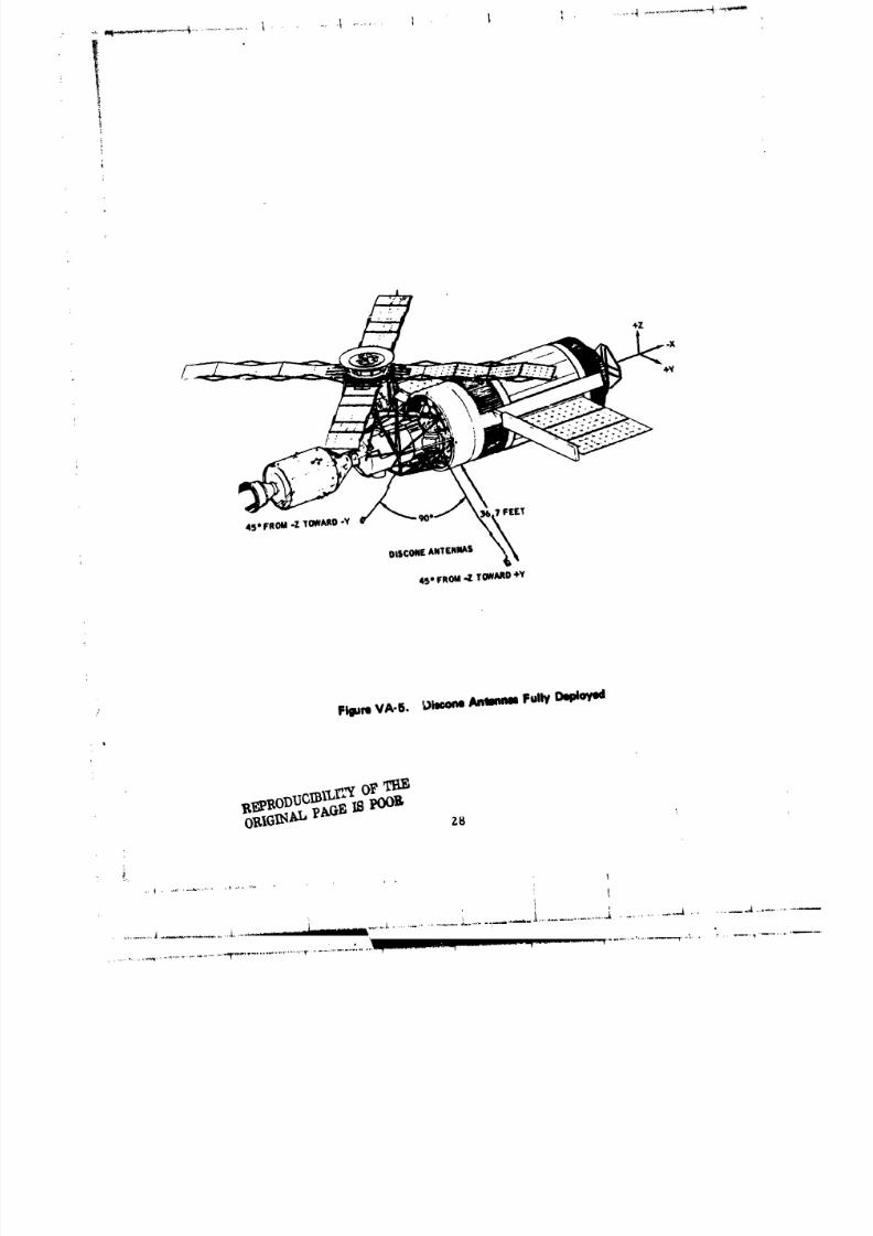
8/8/2019 MSFC Skylab Structures and Mechanical Systems Mission Evaluation
http://slidepdf.com/reader/full/msfc-skylab-structures-and-mechanical-systems-mission-evaluation 45/348
FigureVA-§. _)itooneAntmmmFullyDuldoyed
g_RODUCIB1LI"'Y0_'OELIGI_KI'pAGE IS POOg 28 '*
.%
I
+ ........,,,,.,,,,.,,................_,,p,_.,..,.,,.................................................................................. .................... ........,,,,,.___,, ,.., +. ........ _,,
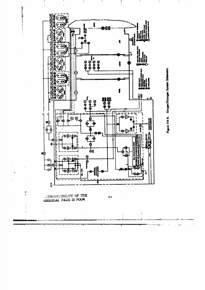
8/8/2019 MSFC Skylab Structures and Mechanical Systems Mission Evaluation
http://slidepdf.com/reader/full/msfc-skylab-structures-and-mechanical-systems-mission-evaluation 46/348
k t

8/8/2019 MSFC Skylab Structures and Mechanical Systems Mission Evaluation
http://slidepdf.com/reader/full/msfc-skylab-structures-and-mechanical-systems-mission-evaluation 47/348
(1) Oxygen tanks. Tanks were required to store a minimum
of 5,985 lb gaseous oxygen at 3,000 pslg to support an estimated Skylab
mission requirement of 4,046 lb. The cylindrical tanks with eliptic.ilheads are made of a 2-in. thick fiber glass winding over stainless steel
liners. A fill valve assembly, consisting of the fill valve, two pressuretransducers and a tank isolation check valve is attached to each tank at
the fill-end dome pl,lg. The oxygen tank was developed and quallfied for
Skylab.
At lift-off the total load in oxygen tanks was 6,112 lb.
The quantity of o_Tgen was sufficient to support the three manned
missions including the duration extension of approximately 23 percent.
During the Skylab missslon, at high beta angles, oxygen tank #4 temperatures
were off-scale high according to telemetry data. Calculations indicated
that the maximum temperatures of th_s tank reached approxlmatelv 225 "F.
A similar tank had been tested at 275 °F with 50,000 cycles (0 - 3000 psi)
showing a maximum st:ength reduction of about 15 percent. Since Skylab
testing was accomplished with pressure at 4,500 psig, it was predicted
that potential strength reduction was not sufficient to cause tank rupture.
Demonstrated oxygen tank capability throughout the remainder of the Skylab
mission verified this prediction. The oxygen tanks and associated tubing
exhibited no detectable leakage during the Skylab mission.
(2) Filter/relief valve assembly. One component, of the
same type, is in each application to filter both oxygen and nitrogen.
The filter, developed specifically for Skylab, is required to remove
i00 percent of particles in excess of i0 micron size. Required flow
through the filter at 70 +20 °F a_d 450 psig inlet pressure is 2.5 Ib/mln
oxygen with a maximum pressure drop of I0 psid.
Estimated operating requirements were 5,938 hr and 25 impulse
cycles. The unit was subjected to static fatigue with oxygen at 4,500 psig
for 8 months, and 1,000 relief valve crack and reseat cycles at 0 to 150
percent flow at 70 "F. Additionally, a successful filtration flow
fatigue test was conducted.
No measurements were provided to determine if the assemblies
were in the filtering or gas bypass modes on-orbit. Gas supply at an
acceptable level was maintained throughout the Skylab mission.
(3) Oxygen pressure regulator assembly. One oxyge_
pressure regulator assembly, containing two parallel circuits for
redundancy is installed in the alrlock. At temperatures from -I0 to 160 °Fthe assembly flows 0.002 to 0.38 ib/min oxygen at inlet pressure of 300
to 3,000 psia and 0.002 to 0.52 Ib/mln at 43_ to 3,000 psia inlet pressure.
Both circuits are required to regulate outlet pressure at 120 +_i0 psig.
The assembly has a single inlet with a i0 micron filter and a single
outlet. Between these two ports the paralleled circuits each contain an
upstream toggle shutoff valve, a regulator and a relief valve isolated
downstream by a check valve. A test port in each circuit is used to verify
relief and check valve operation.
30
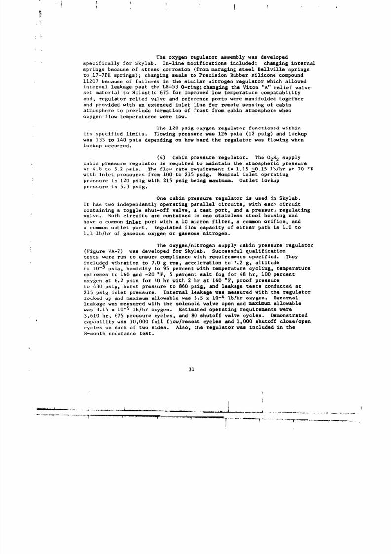
8/8/2019 MSFC Skylab Structures and Mechanical Systems Mission Evaluation
http://slidepdf.com/reader/full/msfc-skylab-structures-and-mechanical-systems-mission-evaluation 48/348
I , 1 T I ,
!:
The oxygen regulator assembly was developed
specifically for Skylab. In-line modifications included: changing internal
springs because of stress corrosion (from maraging steel Bellville springs
to 17-7PH springs); changing seals to Precision Rubber silicone compound
11207 because of failures in the similar nitrogen regulator which allowed
internal leakage past the LS-53 O-ring; changing the Viton "A" relie£ valve
set material to Silastic 675 for improved low temperature compatability
and, regulator relief valve and reference ports were manifolded together
and provided with an extended inlet line for remote sensing of cabin
atmosphere to preclude formation of frost from cabin atmosphere when
oxygen flow temperatures were low.
The 120 psig oxygen regulator functioned within
its specified limits. Flowing pressure was 126 psia (12 psig) and lockup
was 133 to 140 psia depending on how hard the regulator was flowing when
lockup occurred.
(4) Cabin pressure regulator. The O2N 2 supply
cabin pressure regulator is required to maintain the atmospheric pressure
at 4.8 to 5.2 psia. The flow rate requirement is 1.15 +__O.15ib/hr at 70 °F
with inlet pressures from I00 to 215 psig. Nominal inlet operating
pressure is 120 psig with 215 psig being maximum. Outlet lockup
pressure is 5.3 psig.
One cabin pressure regulator is used in Skylab.
It has two independently operating parallel circuits, with each circuit
containing a toggle shut-off valvet a test port, and a pressur: regulating
valve. Both circuits are contained in one stainless steel hoasing and
have a co_unon inlet port with a I0 micron filter_ a common orifice, and
a common outlet port. Regulated flow capacity of either path is 1.0 to
1.3 ib/hr of gaseous oxygen or gaseous nitrogen.
The oxygen/nitrogen supply cabin pressure regulato_
(Figure VA-7) was developed for Skylab. Successful qualification
tests were run to ensure compliance with requirements specified. They
included vibration to 7.0 g rms_ acceleration to 7.2 g_ altitude
to 10-5 psia, humidity to 95 percent with temperature cycling, temperature
extremes to 160 and -20 °F_ 5 percent salt fog for 48 hr, i00 percent
oxygen at 6.2 p_ia for 40 hr with 2 hr at 160 "Fj proof pressure
to 430 psig, burst pressure to 860 psig_ and leakage tests conducted at
215 psig inlet pressure. Internal leakage was measured with the regulatcr
locked up and maximum allowable was 3.5 x 10⁻⁴ Ib/hr oxygen. External
leakage was measured with the solenoid valve open and maximum allowable
was 3.15 x 10⁻⁵ ib/hr oxygen. Estimated operating requirements were
3,610 hr, 675 pressure cycles, and 80 shutoff valve cycles. Demonstrated
' capability was I0,000 full flow/reseat cycles and I_000 shutoff close/open
cycles on each of two sides. Also t the regulator was included in the8-month endurance test.
31
I
"T
I
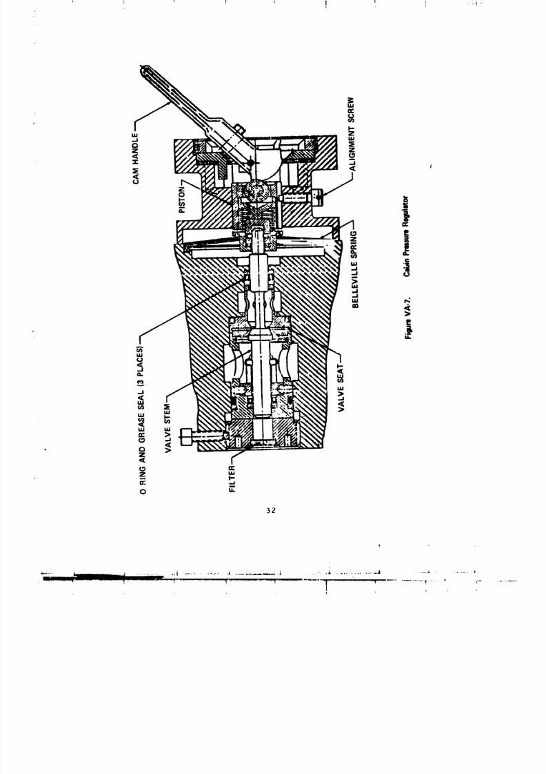
8/8/2019 MSFC Skylab Structures and Mechanical Systems Mission Evaluation
http://slidepdf.com/reader/full/msfc-skylab-structures-and-mechanical-systems-mission-evaluation 49/348
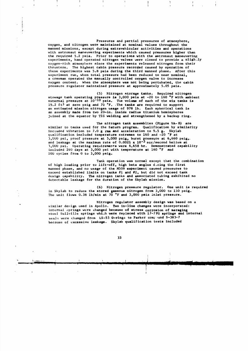
8/8/2019 MSFC Skylab Structures and Mechanical Systems Mission Evaluation
http://slidepdf.com/reader/full/msfc-skylab-structures-and-mechanical-systems-mission-evaluation 50/348
Pressures and partial pressures of atmosphere,
oxygen, and nitrogen were maintained at nominal values throughout the
manned missions, except during extravehicular activities and operationswith astronaut maneuvering experiments which caused pressures higher than
the required 5.2 pals. Prior to operations with the astronaut maneuvering
experiments, hand operated nitrogen valves were closed to provide a sligh;ly
o×ygen-rich atmosphere since the experiments released nitrogen from their
thrusters. The highest cabin pressure recorded caused by operation of
these experiments was 5.8 psia during the third manned phase. After thls
experiment run, when total pressure had been reduced to near nominal,
a crewman operated the manually controlled oxygen valve to increase
oxygen content. When the atmosphere was not being pertubated, the cabin
pressure regulator maintained pressure at approximately 5.05 pals.
(5) Nitrogen storage tanks. Required nitrogen
stowage tank operating pressure Is 3,000 psia at -20 to 160 "F with ambient
external pressure at 10 -10 psia. _le volume of each of the six tanks is
19.2 ft3 at zero psig and 70 "F. ,The tanks are required to support
an estimated mission nitrogen usage of 978 lb. Each spherical tank is
an a:ssembly made from two 20-in. inside radius titanium hemispheres
Joined at the equator by TIC welding and strengthened by a backup ring.
The nitrogen tank _Isemblles (Figure VA- 8) are
similar to tanks used for the Saturn program. Qualification by similarity
included vibration to 7.0 g rms and acceleration to 9.5 g. $kylab
qualification included temperature extremes to 160 and -20 _F at
3,000 psi, proof pressure at 5,000 psig, burst _ressgre at 6,660 psig,.and leakage at the maximum rate of 0,0021 x I0 -_ scc/second helium at
3,000 ps£. Operating requirements were 6,658 hr. Demonstrated capability
included 240 days at 3.000 psi wlth temperature at 160 "P andI00 cycles from 0 to 3.000 pslg.
Tank operation was normal except that the combination
of high loading prior to lift-off, high beta angles d_ring the first
manned phase, and no usage of the M509 experiment caused pressures to
exceed established limits on tanks _i and #2. but did not exceed tank
design capability. The nitrogen tanks and associated tubing exhibited no
detectable leakage for the duration of the Skylab mission.
(6) Nitrogen pressure regulator. One unit is required
in Skylab to reduce the stored gaseous nitrogen from 3,000 to 150 psig.
The unit flows 0.38 ib/mln at 70 "F and 3,000 psia inlet pressure.
Nitrogen regulator assembly design was based on a
similar design used in Apollo. Two In-llne changes were incorporated:
internal _prings were changed because of stress corrosion of restaging
steel I_ellvttle springs whiah were replaced vlth 17-7PII springs and internal
seals were changed from L5-53 O-flags to Parker corer _und S-383--7
because o£ excessive leakage. Skylab qualification tests included
33
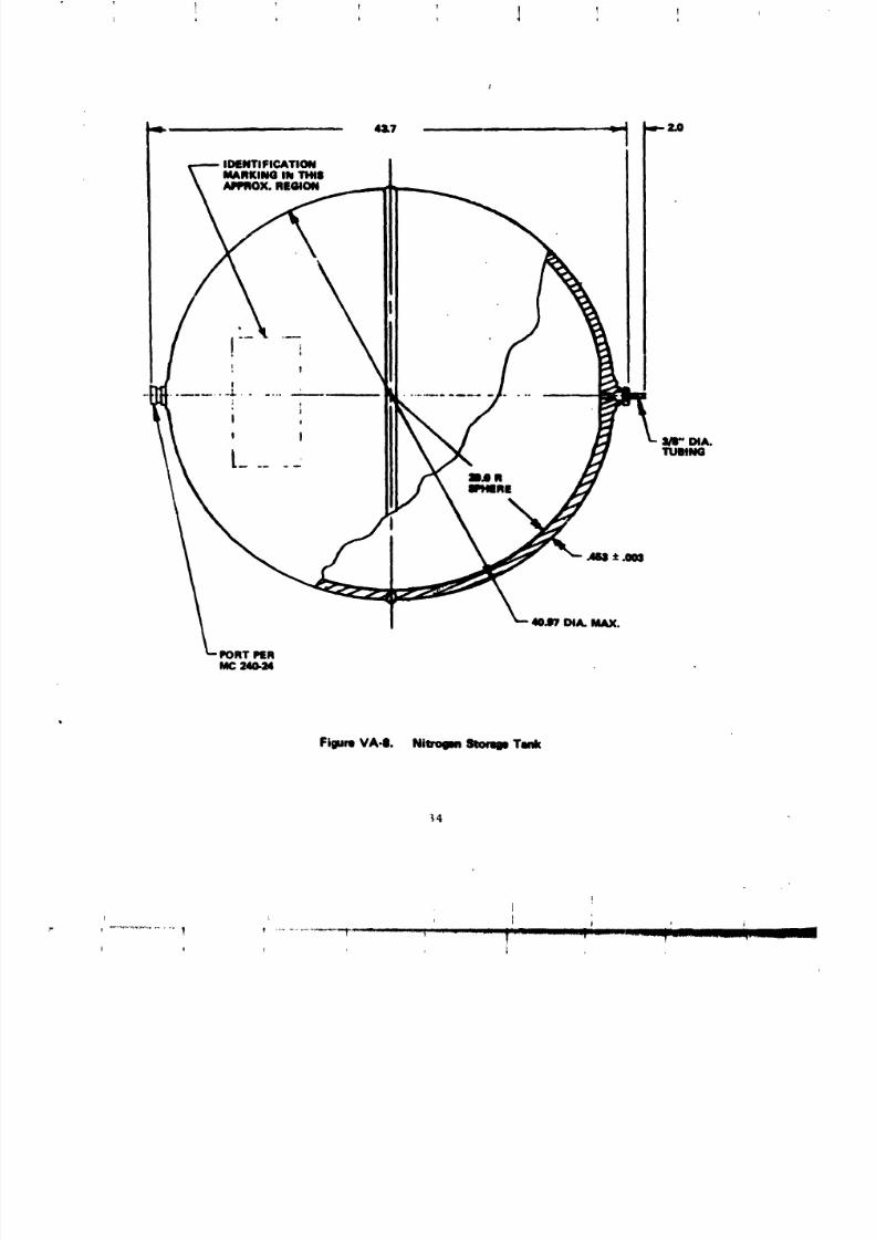
8/8/2019 MSFC Skylab Structures and Mechanical Systems Mission Evaluation
http://slidepdf.com/reader/full/msfc-skylab-structures-and-mechanical-systems-mission-evaluation 51/348
IDENTIFICATION
MARKINGlibTI,N|MPROX. REGION
it
I
; !!
I
t I _-W DIA.
..... TUBINGmJ R8PIIqRll
FigureVA-II. NierolM _ Tank
_4
8/8/2019 MSFC Skylab Structures and Mechanical Systems Mission Evaluation
http://slidepdf.com/reader/full/msfc-skylab-structures-and-mechanical-systems-mission-evaluation 52/348
!
vibration to 7.0 g rms, acceleration to 7.4 g, altitude to 10 -8 psia,
temperature extremes to 160 and -20 °F, and burst pressure to
12,000 psig for the regulator and toggle valve and to 840 psi s for the
check valva. Operating requirements were estimated to be 5,938 hr, 675
regulating cycles, and 80 shutoff cycle_. Demonstrated capability was
i0,000 regulator cycles, and 100 relief valve cycles plus performance
during the 8-month endurance test. During acceptance, the regulators
and check valve were proof tested to 6,000 and 450 psig, respectively,
and leaked checked. At Iockup, internal maximum leakage was 3.27 x 10⁻⁴ ib/hr
nitgrogen. Check valve leakage was less than 3.15 x 10⁻⁵ ib/hr o_rgen
at 210 pslg. Shutoff leakage was less than 3.15 x 10 -5 lb/hr oxygen
with deita pressure of 3,000 pslg.
The nitrogen pressure regulator exhibited anomalous
behavior by allowing regulated pressure to drift downward. It had dropped
from 160 psia on the 5th day of the first manned phase to 140 psia on the
21st day of the first manned phase. Two days later, the crew verified
that both nitrogen regulator toggle valves were open and the on-boardmeter was reading 140 psia. Telemetry also read approximately 140 psia.
No further decrease was seen during the first manned phase. When the
molecular sieve was deactivated on the last day of the first manned phase,
the outlet pressure began to increase and was 175 psia 3 days later, at
which time the lines downstream of the regulator vented to 4 psia.
At activation by the second Skylab crew, the nitrogen
regulator outlet was 158 psia. Twenty-days later, the pressure
had dropped to 150 psia. The pressure contintued to drift downward until
it was 141 psia on the 28th day of the second manned phase. On this
day, during extravehicular activities, the pressure increased to 145 p:;ia.
The reason for this is unknown. The pressure decreased to 141 psia the
following day.
Since the terminating of nitrogen regulator flow
had somehow restored the outlet pressure at the end of the first manned
mission, it was decided to close one regular toggle valve and leave it
closed for 5 days in an attempt to increase the outlet pressure.
Five days later, on the 34th day of the second manned phase, the regulator
outlet pressure was 140 psia. At that ti_, toggle valve A was opened and
toggle valve B was closed. The regulator outlet pressure immediately
Increased to 155.5 psia. Five days later, pressure had decreased
to 151 l>sla. Toggle valve A was closed and valve B opened. The regulator
outlet pressure fell immediately to 148 psia and in 5 more days
h._d decreased to 145 psia. Toggle valve B was closed and toggle valve A
was opened and the pressure increased to 155.5 psia. It was decided
that rather than _witch toggle valves every 5 days, they would be switched
when the nitrogen regulator outlet pressure approached a zero flow
_ondition. By deactivation the pressure had decreased to 146 psia. When
the m.]_cular sieve supply was closed, the regulator outlet pressureiucrea_L; L_ _65 psia,
35
I
8/8/2019 MSFC Skylab Structures and Mechanical Systems Mission Evaluation
http://slidepdf.com/reader/full/msfc-skylab-structures-and-mechanical-systems-mission-evaluation 53/348
! ! ! IT T
!
t e
At deactivation by the second Skylab crew, both
toggles A and B we.re opened per procedure. The supply solenoids were clo_,ed
and the regulator p_essure slowly drifted down as the system leaked during
storage. The toKKle valve conflgurstlon was not chansed durlns act£vatlon
by _he third Skylab crew. On the seventh day of the third manned phase,
toggle valve A was closed in 26 days. The pressure drifted only from
155 psia to 148 psla. At that time the crew inadvertently closed the
open tog$1e valve B. When they reconfIsurad the system , they opened
A and the pressure went up to 160 p_la. During the next 18 days the
Fressure had drifted to 150 psla ancL by the end of the alsslon, the pressure
was still 150 psla.
In addJtlon to the above described onboard troubleshooting,
ground tests were r.jn to try to dupllcate regulator characterlstlcs. These
included low demand and malamute tests, but the symptoms were not re-
produced. The reason for the drift In outlet regulator pressure has not
been established. The oxygen regulator is _chanica1_y very si_Llar, butdid not displ_y these drift characteristics.
(7) Water tank pressure regulator. One regulator
of this type is required in the system to reduce gaseous nitrogen pressure
from 150 psia to 5_+0.2 psla at a flow of 0.005 to 0.05 ib/hr for
control of pressure in the telescope mou_t control and display coolant
water tank and the two suit cooling loop water tanks. Inlet pressure
ran;e for operaclon is 80 to 210 _sla and lockup was required at 5.5 psla
out i.et maximum.
The Laxlmum acceptable leakage rate was 2.92 x I0 -5 Ib/hr
nitrogen, both internally for the shutoff condltlon and for external
leakage, with pressure at 210 psld. In the lookup conditl¢_, mLaxlmumallowable leakage was 3.24 x 10 -5 Ib/hr nitrogen. Esti_ted operat/mg
requirements were 5,938 hr and 1,200 cycles. Skylab capabilStles
demonstrated included lO0 full cycles and 10,000 automatlc cycles plus
operation as one of the units Included In the 6-month endurance test.
The water tank pressure regulator operated properly
throughout the m_sslon. During launch the relief portion of the zesulator
vented the alrlock water tanks from sea level amblent to 6.0 psla mud
locked up. This was well within the stated requlre_nts. The regulator
maintained tank pressures of 5.2 to 5.5 psla throughout the Skylab _Lsalon.
This was also well within the stated requlremsnt8.
b. Thermal control system. Pasalve therma_ control systems
are incorporated into all Skylab modules. The raqu£r_nt for activethermal control for the habitable Skylab voluam and sou externally mounted
components is provided by the alrlock. The system is required to reject
heat through a radiator. In addltlon to the radlator, system daslSn
required pumps, valves, heat exchangers, thermal capacitors, cold plates,
36
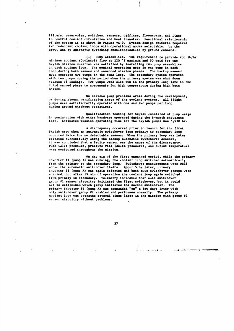
8/8/2019 MSFC Skylab Structures and Mechanical Systems Mission Evaluation
http://slidepdf.com/reader/full/msfc-skylab-structures-and-mechanical-systems-mission-evaluation 54/348
t I
filters, reservoirs, switches, sensors, o_iflces, flow_eters, and i_neI
to control coolant circulation and heat transfer. Functional relatlonsh!p
of the syste= Is as shom, in Figure VA-9. System des_sn criteria required
two redundant coolant loops wlth operational nodes sel_ctable: by thecrew, and by automatic swltchlns enabled/dliabied by ground coInd.
(I) Pump •ssemblles. The requirement to provide 230 ib/hr
m£nimu_ coolant (Coolanol) flow at 120 "F Ilium and 50 paid for the
Skylab mission duration was satisfied by Inatalllns two pump aasemblies
in each coolant loop. The noaln•l operatins mode is one pump in each
loop during both manned and unmanned ILtsalon phases. The backup manned
mode operates two punps in the same loop. The secondary system operated
with two pumps durlns the period when the pr_ry system was shut down
because of leakage. Two pumps war• also run in the primary Ioo; late in the
third u_nned phase to compensate for hlsh temperature durlnB hlsh beta
angles.
No serloua pump problems •rose durlns the development,or during ground verification testa of the coolant systems. All fllsht
pumps were satisfactorily operated with one and two pumps per loop
durins ground checkout operations.
Qualification teitlnI for Skylab conslsted of pump usage
In conjunction wlth other hardware operated durlns the 8-month endurance
test. Estimated mission operatlns tlmme for the Skyl•b pimps waI 5,938 hr.
& discrepancy occurred prior to launch for the flrat
$kylab crew when an automatic swltchover from prlma_y to secondary loop
occurred twice for no detectable reason. When the prlmary loop was later
operated _uccessfully uslnI the backup •utom_mtlc awltchover sensors,
It was cot_cluded that a faulty sensor was the cause of the dlacrepancy.
Pump l,ilet pressure, pressure rlse (delta pressure), and outlet tanperature
were monltored throushout the mission.
On day slx of the first unmanned period, while the primary
inverter #I (pump A) was runnln$, the coolant i_ up switched automatlcaily
from the primary to the secondary loop. $wltchover measure_nts were well
above the automatic swltchover limits. About 5 hr later, priory
inverter #I (pump A) was asaln selected and both auto sw_tchover groups were
enabied, but after 19 min of operation Lhe coolant loop •Sain switched
from primary to secondary. Telemetry Indlcated that auto swltchover
Stoup #I sensor circuitry initiated the first s_itchover, but It could
not be determined which sroup initiated the second swltchover. The
primary inverter #I (pump A) was com_mnded "on" • few days l_ter wlth
only switchover sroup #2 enabled and perfonma normally. The primarycoolant loop was operated several times later In the alssinn with Iroup #2
sensor circuitry without problems.t
37
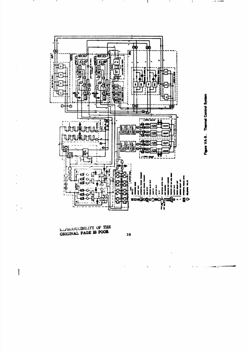
8/8/2019 MSFC Skylab Structures and Mechanical Systems Mission Evaluation
http://slidepdf.com/reader/full/msfc-skylab-structures-and-mechanical-systems-mission-evaluation 55/348
I._£¢ubl.J_WILI'I'YOFT]:[F,O_GINAL PAGEm POOR
)8
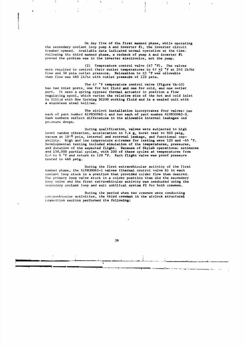
8/8/2019 MSFC Skylab Structures and Mechanical Systems Mission Evaluation
http://slidepdf.com/reader/full/msfc-skylab-structures-and-mechanical-systems-mission-evaluation 56/348
I I 1 I I ! Ib
i
On day five of the first manned phase, while operating
the secondary coolant loop pump A and inverter #i, the inverter circuit
breaker opened. Available data indicated normal operation at the time.
Following the third manned phase_ a recheck of pump A and inverter #i
proved the problem was in the inverter electronics, not the pump.
(2) Temperature control valve (47 °F). The valves
were required to control their outlet temperatures to 47 +--2°F at 240 Ib/hr
flow and 50 psia outlet pressure. Relaxation to +3 °F was allowable
when flow was 460 ib/hr with outlet pressure of ii0 psia.
The 47 °F temperature control valve (Figure VA-IO)
has two inlet ports, one for hot fluid and one for cold, and one outlet
port. It uses a spring opposed thermal actuator to position a flow
regulating spool, which varies the relative size of the hot _d cold inlet
is fillzd with Dow Cornlng DC200 working fluid and is a sealed unit witha stainless steel bell_ws.
The airlock installation incorporates four valves: two
each of part number 61V830062-1 and two each of part number 61V830062-3.
Dash numbers reflect differences in the allowable internal leakages _Jnd
prussure drops.
During qualification, valves were subjected to high
level random vibration, acceleration to 7.4 g, burst test to 920 psig,
vacuum at 10-8 psia, internal and external leakage_ and functional cap-
ability. High and low temperature e_tremes for testing were 120 and -65 °F.
Developmental testing included simulation of the temperatures, pressures,
and duration of the expected flight. Because of Skylab operatlonaJ, estimatesand 150,000 partial cycles, with 200 of these cycles at temperatures from
120 to 0 °F and return to 120 °F. Each flight valve was proof pressure
tested to 460 psig.
During the first extravehicular activity of the first
manned phase, the 61V830062-I valves (thermal control valve B) in each
coolant loop stuck in a position that provided colder flow than desired.
The prlmary loop valve stuck in a colder position than did the secondary
loop valve and the first extravehicular activity was conducted using the
secondary coolant loop and suit umbilical system #2 for both crewmen.
During the period when two crewmen were conducting
e×t_avehicular activities, the third crewman in the airlock structural
transition sectlon performed the following:
39
i
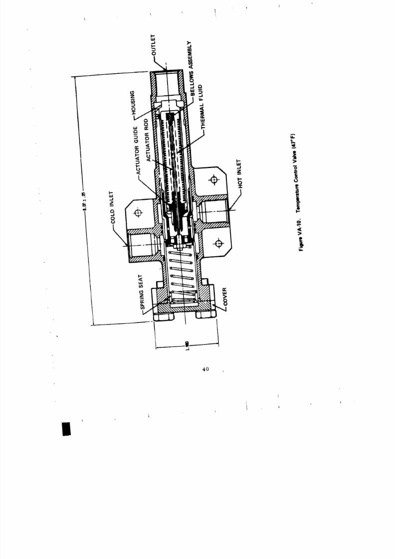
8/8/2019 MSFC Skylab Structures and Mechanical Systems Mission Evaluation
http://slidepdf.com/reader/full/msfc-skylab-structures-and-mechanical-systems-mission-evaluation 57/348
40
t
8/8/2019 MSFC Skylab Structures and Mechanical Systems Mission Evaluation
http://slidepdf.com/reader/full/msfc-skylab-structures-and-mechanical-systems-mission-evaluation 58/348
o Turned both pumps on in suit umbilical system #I
with no flow recorded indicating " ozen
condition.
o Turned on primary coolant loop inverter #i
(pump A) with bypass valve in "EVA" position.
Temperature control valve outlet went off
scale low at 0 °F. Inverter and pump turned
off.
Following extravehicular activities, after suit umbilical
system #2 was turned off, the secondary aoolant loop thermal control
valve moved toward an interim position to maintain a 47 OF outlet tem-
perature, hut it again stuck. Without the heat load from the suits,
valve outlet temperature dropped to 35 °F, causln_ a caution alarm.
The secondary coolant loop was turned off and the primazy turned on.
The molecular sieve fan became noisy, probably caused by frozen condensate.
The coolant loops were switched from primary to secondary _nd another
caution and warning alarm occdrred. Various alternate operating modes
were tried with no success. The telescope mount control and display
panel was powered up to approximately 170 W to add heat via its
cooling loop to the secondary coolant system. Also, two liquid cooled
garments were attached to suit umbilical system #2 and placed by the
warmest workshop water tank. This combination led to a stabilized
40 °F temperature at the secondary coolant loop thermal control valve
outlet.
Warming of the thermal control valve sensor cartridge
causes it to expand, providing a positive movement. Cooling of the sensor
cartridge causes it to contract and the opposite movement is provided
by a spring. The sensor cartridge in the nonoperating primary loop was
allowed to warm, providing sufficient force I"o free the thermal control
valve. About 48 hr after completion of the extravehicular activity,
when the primary system was operated with two pumps, the thermal control
valve outlet temperature returned to 47 "F. Operation with one pump
was also satisfactory.
Four days after the exCravehicular activity, the second
coolant loop thermal control valve outlet temperature was still 40 °F.
Pumps were turned off for about 22 hr and when again turned on,
the thermal control valve modulated, maintaiQing an outlet temperature
c>f 47 OF.
Bypass valves were in the "BY-PASS" position when the
thermal control valve cartridges were warmed and they remained in the
"BY-PASS" position throughout the remainder of the Skylab mission.
As a result of the sticking thermal control valves in
both co_lant loops, a heater and controller were built and launched
with tl_e su_:ond crew to provide the capability to add heat to the suit
_:ooJJng loop and thereby add heat at the hot inlet to the thermal control
valves, should either of them again stick. The heater and controller
were never used.
41
jt I A _ t _
8/8/2019 MSFC Skylab Structures and Mechanical Systems Mission Evaluation
http://slidepdf.com/reader/full/msfc-skylab-structures-and-mechanical-systems-mission-evaluation 59/348
1 1 1 I T/I
After beth the primary and secondary coolant loop
thermal control valves were unstuckp both maintained temperatures within
the control band of 47 +--2°F. Review of performance data indicated that
the secondary loop valve was somewhat sluggish. As a result, subsequent
eztravehlcular activities were conducted with all crewmen on suit cooling
system #i with the primary coolant loop until its loss during the second
manned phase because of leakage. A decision was made to use the secondary
loop rather than have the second Skylab crew perform their second
extravehicular with only oxygen cooling. During this period of operations,
the secondlry coolant loop thermal control valve outlet temperature
dropped from 47.3 °F to 41.7 °F and stayed at approximately that temperature
for the remainder of the second manned phase.
The third extravehicular activity by the second Skylab
crew was accomplished with oxygen cooling since the primary loop did
not have sufficient coolant and the thermal control valve in the secondary
loop might stick in a less desirable position if liquid suit cooling
was used again during extravehicular activities.
The outlet temperature 3f the secondary coolant loop
thermal control valve dropped to approximately 40 °F during the third
unmanned period when the loads on the system were very low. No attempt
was made to free the valve since it was stuck in an ac:eptable position,
and based on past experience when the loop was cycled off and on, in an
attempt to unstick the valve, the valve outlet actually moved to a colder
position than before. Had this occurredp the heater may have been required
to maintain acceptable temperatures during the third manned phase if
the planned primary coolant loop reserviclng was not successful.
The secondary loop was operated with the thermal control
valve stuck until the earth observation pass on mission day 58 ofthe third manned phase when the higher radiator outlet temperature
increased the valve inlet temperature. The hot leg flow was decreased
to 114 ib/hr durinf; the pass, but returned to the 40 °F position following
the pass. During the earth observation pass on mission day 60 of the
third manned phase, the valve decreased the hot flow to 0 Ib/hr,
but again returned to the original position. During the earth observation
pass on mission day 64 of the third manned phase, the valve came unstuck
and began to modulate following the pass. It continued to modulateuntil the end of the mission.
After reservlclng the primary coolant loop during
the third manned phase, all extravehicular activities were accomplished
using the primary coolant loop and suit cooling system #i.
(3) Temperature control valve (40 "F). The two
temperature control valves (one in each loop) are used to maintain a nominal
40 °F coolant temperature to the airlock batteries by controlling the mix
42
i
8/8/2019 MSFC Skylab Structures and Mechanical Systems Mission Evaluation
http://slidepdf.com/reader/full/msfc-skylab-structures-and-mechanical-systems-mission-evaluation 60/348
of cold fluid from the radiator via a heat exchanger and hot fluid
from the outlet of the cooling system. The design flow rate requirement
was 500 ib/hr at 40 "F with temperatures to _i0 "F. Allowed pressure
drop was 1.22 psid.
The 40 °F temperature control valve has two inlet portsp
one for hot fluid and one for cold_ and one discharge port. It uses
a sprlng-opposed thermal control element (wax mixture with a high coefficient
of expansion) to position a flow-regulating sleeve, which proportionately
opens and clo_es the hot and cold inlet ports to provide a fluid mix of
the desired temperature. "Flight operation was satisfactory."
(4) Thermal capacitor. This unit (Figure VA-II)
is a phase change heat sink installed downstream of the radiator to supple-
ment radiator performance. The unit consists of primary and secondary
coolant loop cold plates sandwiched between honeycomb-type chambers containing
19.6 ib of paraffin (Tridecane). Melting of the Trldecane occurs at
22.35 °F with a heat of fusion of 66.5 Btu/ib. A structural transition
occurs at -0.7 °F with an associated heat absorption of 17.9 Btu/Ib.
The c_pacltor is able to store heat by melting while the vehicle is on
the hot side of the orbit and reject heat (freeze) on the cold side.
Flow of 220 ib/hr minimum coolant at 75 °Fj with a maximum pressure drop
of 2.1 psid was required. Cold plate operating pressure was 140 psig
and wax chamber operating pressure was 40 pslg.
Two problems were encountered during Skylab testing.
The capacitor supplied for use in the workshop refrigeration system developed
a crack during bench test at MDAC-W; it was determined to be the result
of more rapid temperature swings than the alrlock qualification provided.
Also_ Napco foam insulation bulged and debonded from the capacitor when
exposed to vacuum. The foam specimens tested contlnually failed whenexposed to vacuum. The rapid temperature swing problem required redesign
and requallfication and the foam problem was overcome by replacing it
with maltilayers of fiber glass sheets.
Qualification tests included high-level vibratlon_
altitude to 10-6 pslaj temperature extremes of 160 and -140 °F, burst
pressure to 350 pslg, 200 complete freezing and thawing cycles, 2,400
partial freezing and thawing cycles, and temperature control performance.
The thermal capacitor melted only during the high beta angle conditions
that occurred during the third manned phase. Storage capability aidedthermal control at this time and performance was as designed.
(5) Coolant filters. The coolant filter assembly
, was used in the airlock cooling system to filter all solid contaminantslarger than i00 microns out of the coolant fluid. Two of these double
43
iI
/ 1 J _ j
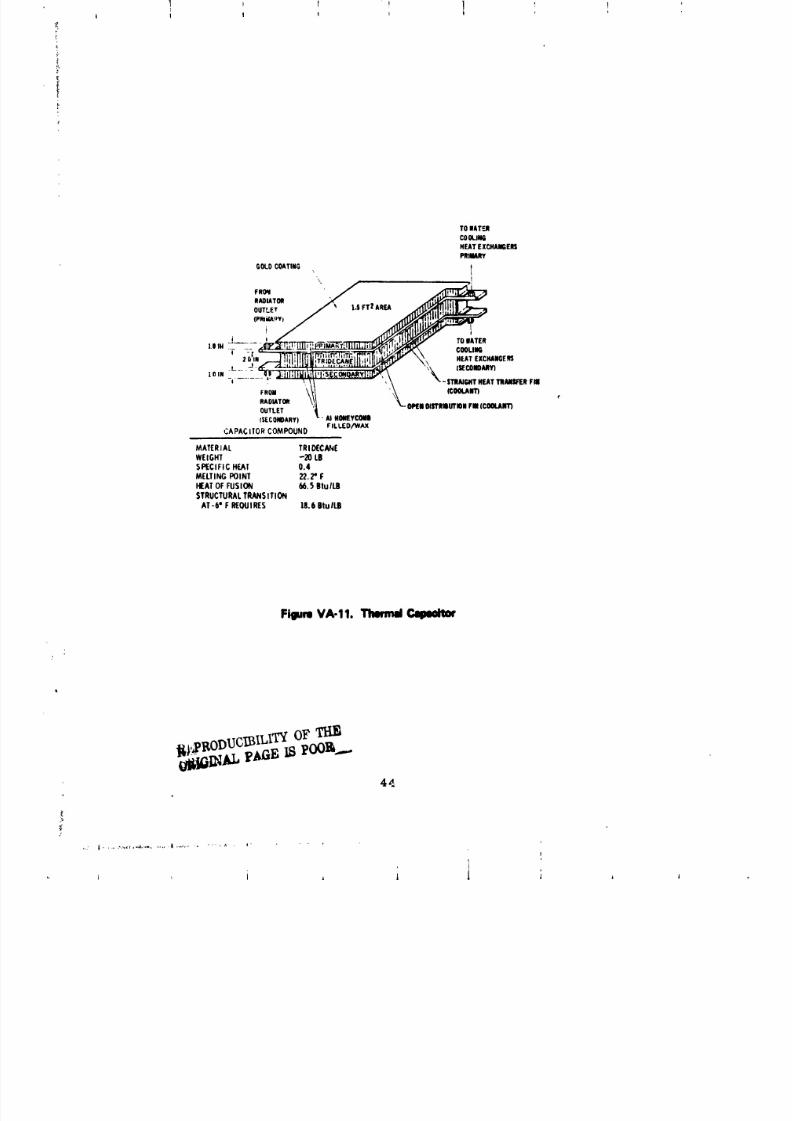
8/8/2019 MSFC Skylab Structures and Mechanical Systems Mission Evaluation
http://slidepdf.com/reader/full/msfc-skylab-structures-and-mechanical-systems-mission-evaluation 61/348
TOIAT_
COOU_NEATXCHANGERSPNflMRY
GOLOCOATING
'\ t
.OlATOn ._, ,, - ..E,_
' _,__ " \ %" STRAIGHTEATTNAIISlFI[RlU
RAOIATO_ \_.1 "_ e
OUTLET '_ _ 01_IIOlSTRIUTIQNIB(COOLANT)(SECOIB)ARY|_- AINOIWEYCOMN
CAPACITORCOMPOUND FILLED/WAX
MATERAL TRIDECN4EWEGHT -20 LB
SPECIFICHEAT 0.4
MELTINGPOINT 22.2"F
HEATOFFUSION 66._6tu ILilSTRUCTURALRANSITION
AT-6" F REOUIRES )8.6 Btul_
Flllm VA-11. Tlwmd Calttdtm'
I,eODUCm U$OF
44
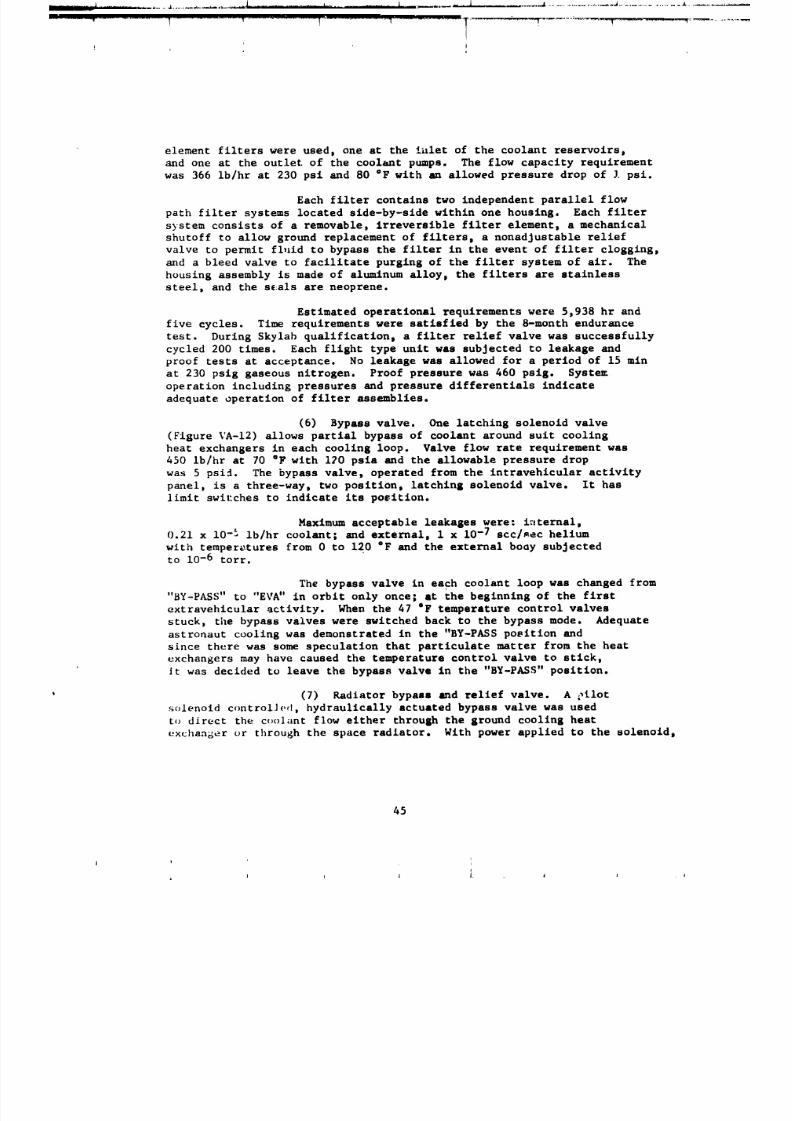
8/8/2019 MSFC Skylab Structures and Mechanical Systems Mission Evaluation
http://slidepdf.com/reader/full/msfc-skylab-structures-and-mechanical-systems-mission-evaluation 62/348
L I J.......................................................... .........._.....-._..........................................................
/j
element filters were used, one at the iulet of the coolant reservoirsp
and one at the outlet of the coolant pumps. The flow capacity requirement
was 366 ib/hr at 230 psi and 80 °F with an allowed pressure drop of I psi.
Each filter contains two independent parallel flow
path filter systems located slde-by-side within one housing. Each filter
system consists of a removable, irreversible filter element, a mechanical
shutoff to allow ground replacement of filters, a nonadjustable relief
valve to permit fluid to bypass the filter in the event of filter clogging,
and a bleed valve to facilitate purging of the filter system of air. The
housing assembly is made of aluminum alloy, the filters are stainless
steel, and the s_:als are neoprene.
Estimated operational requirements were 5,938 hr and
five cycles. Time requirements were satisfied by the 8-month endurance
test. During Skylab qualification, a filter relief valve was successfully
cycled 200 times. Each flight type unit was subjected to leakage and
proof tests at acceptance. No leakage was allowed for a period of 15 min
at 230 pslg gaseous nitrogen. Proof pressure was 460 psig. System
operation including pressures and pressure differentials indicate
adequate operation of filter assemblies.
(6) Bypass valve. One latching solenoid valve
(Figure VA-12) allows partial bypass of coolant around suit cooling
heat exchangers in each cooling loop. Valve flow rate requirement was
450 Ib/hr at 70 "F with 120 psia and the allowable pressure drop
was 5 psi_. The bypass valve, operated from the intravehicular activity
panel, is a three-way, two position, latching solenoid valve. It haslimit swil:ches to indicate its po_itlon.
Maximum acceptable leakages were: i_tternal,
0.21 x 10-_ lb/hr coolant; and external, 1 x 10-/ scc/aec helium
with temperatures from 0 to 120 "F and the external boay subjected
to 10-6 torr.
The bypass valve in each coolant loop was changed from
"BY-PASS" to "EVA" in orbit only once; at the beginning of the first
extravehicular activity. When the 47 "F temperature control valves
stuck, the bypass valves were switched back to the bypass mode. Adequate
astronaut cooling was demonstrated in the "BY-PASS poeltion and
since there was some speculation that particulate matter from the heatexchangers may have caused the temperature control valve to stick,
It was decided to leave the bypass valve in the "BY-PASS" position.
(7) Radiator bypass and relief valve. A _ilot
solenoid controlJed, hydraulically actuated bypass valve was used
to direct the coolant flow either through the ground cooling heat
exchanger or through the space radiator. With power applied to the solenoid,
45
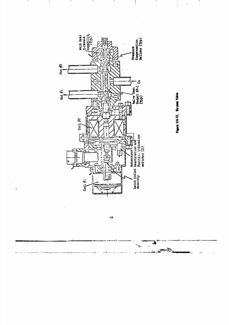
8/8/2019 MSFC Skylab Structures and Mechanical Systems Mission Evaluation
http://slidepdf.com/reader/full/msfc-skylab-structures-and-mechanical-systems-mission-evaluation 63/348
i 1 I I Ii
I L
66
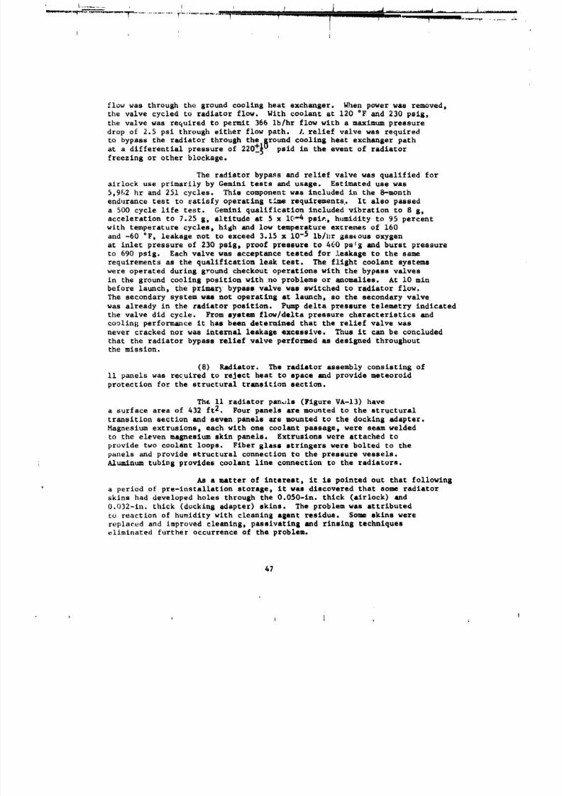
8/8/2019 MSFC Skylab Structures and Mechanical Systems Mission Evaluation
http://slidepdf.com/reader/full/msfc-skylab-structures-and-mechanical-systems-mission-evaluation 64/348
flow was through the ground cooling heat exchanger. When power was removed,
the valve cycled to radiator flow. With coolant at 120 "F and 230 psig,the valve was required to permit 366 ib/hr flow with a maximum pressure
drop of 2.5 psi through either flow path. A relief valve was required
to bypass the radiator through the Rround coolin8 heat exchanger path
differential pressure of 220+_0 psid in the event of radiatort a
freezing or other blockage.
The radiator bypass and relief valve was qualified for
airlock use primarily by Gemini tests and usage. Estimated use was
5,992 hr and 251 cycles. This component was included in the 8-month
endurance test to satisfy operating time requirements,. It also passed
a 500 cycle life test. Gemini qualification included vibration to 8 g,
acceleration to 7.25 g, altitude at 5 x 10⁻⁴ pai_, humidity to 95 percent
with temperature cycles, high and low temperature extremes of 160
and -60 °F, leakage not to exceed 3.15 x 10⁻⁵ ib/hr gaseous oxygenat inlet pressure of 230 psi8, proof pressure to 460 pats and burst pressure
to 690 psig. Each valve was acceptance tested for leakase to the same
requirements as the qualification leak test. The flight coolant systems
were operated during ground checkout operations with the bypass valves
in the ground cooling position with no problems or anomalies. At i0 min
before launch, the primer) bypass valve was switched to radiator flow.
The secondary system was not operating at launch, so the secondary valve
was already in the radiator position. Pump delta pressure telemetry indicated
the valve did cycle. From system flow/delta pressure characteristics and
cooling performance it has been determined that the relief valve was
never cracked nor was internal leakage excessive. Thus it can be concluded
that the radiator bypass relief valve performed as designed throughoutthe mission.
(8) Radiator. The radiator assembly consisting of
Ii panels was required to reject heat to space and provide meteoroid
protection for the structural transition section.
Th£ II radiator panels (Figure VA-13) have
a surface area of 432 ft2. Four panels are mounted to the structural
transition section and seven panels are mounted to the docking adapter.
Magnesium extrusions, each with one coolant passage, were seam welded
to the eleven magnesium skin panels. Extrusions were attached to
provide two coolant loops. Fiber glass stringers were bolted to the
panels and provide structural connection to the pressure vessels.
Aluminum tubing provides coolant llne connection to the radiators.
As a matter of interest, it is pointed out that following
a period of pre-installation storage, it was discovered that some radiator
skins had developed holes through the O.050-in. thick (airlock) and
0.032-in. thick (docking adapter) skins. The problem was attributed
to reaction of humidity with cleaning agent residue. Some skins were
replaced and improved cleaning, passivatlng and rinsing techniques
eliminated further occurrence of the problem.
47
ii i i i I
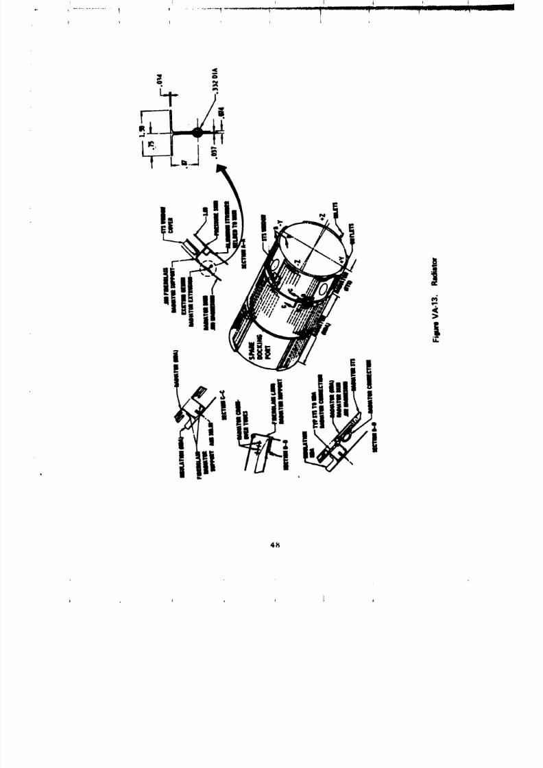
8/8/2019 MSFC Skylab Structures and Mechanical Systems Mission Evaluation
http://slidepdf.com/reader/full/msfc-skylab-structures-and-mechanical-systems-mission-evaluation 65/348
41_
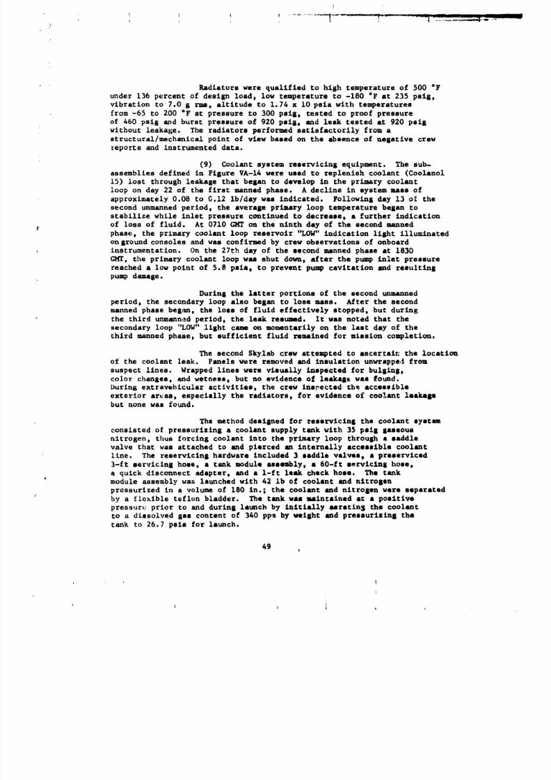
8/8/2019 MSFC Skylab Structures and Mechanical Systems Mission Evaluation
http://slidepdf.com/reader/full/msfc-skylab-structures-and-mechanical-systems-mission-evaluation 66/348
?
Radiators were qualified to high temperature of 500 "F
under 136 percent of design load, low temperature to -180 "F •t 235 psis,
vibration to 7.0 g rms, altltude to 1.74 x I0 psla with temperatures
from -65 to 200 °F at pressure to 300 pslg, tested to proof pressureof 460 psig and burst pressure of 920 psIs0 and leak tested at 920 psis
without leakage. The radiators performed satlsfactozily from a
structural/mechanlcal point of view based on the absence of negative crew
_eports and instrumented data.
(9) Coolant system reservlcln S equipment. The sub-
assemblies defined in Figure VA-14 were used to replenish coolant (Coolanol
15) lost through leakage that began to develop in the primary coolant
loop on day 22 of the first manned phase. A decline in system mus of
approximately 0.08 to C.12 ib/day was indlc•ted. Following day 13 ol the
second unmanned period, the average primary loop temperature began to
stabilize while inlet pressure continued to d•crease, a further indication
of loss of fluid. At 0710 GI4T on the ninth day of the second manned
phase, the primary coolant loop reservoir '_OW" indication light illuminated
on ground consoles and was confirmed by crew observations of onbo•rd
instrumentation. On the 27th day of the second manned phase at 1830
GMT, the primary coolant loop was shut down, after the pump inlet pressure
reached a low point of 5.8 psi•, to prevent pump cavit•tlon 8rid r•sultlnS
pump daumge.
During the latter portions of the second unmanned
period, the secondary loop also began to lose mass. After the second
manned phase beg_n, the loss of fluid effectively stopped, but during
the third unmann,_d period, the leak resumed. It was noted that the
secondary loop "LOW" light came on momentarily on the last day of the
third manned phase, but sufficient fluid remained for mission completion.
The second Skylab crew attempted to •scertai_ the location
of the coolant leak. Panels were removed and insulation unwrappe,_ from
suspect lines. Wrapped llnes were vlsu•lly inspected for bulging,
color changes, and wetness, but no evidence of leakqe was found.
During extravehicular activities, the crew Inspect•d th_ accesslbl•
exterior areas, especlally the r•dlators, for evidence of coo!ant le•kapbut none was found.
The method designed for reservlclng the coolant system
consisted of pressurizing a coolant supply tank with 35 pslg gaseous
nitrogen, thus forcing coolant into the primary loop through a saddle
valve that was attached to and pierced an intern•fly •ccesslble coolant
llne. The reservlcing hardwar• included 3 saddle valve, a preservlced3-ft servicing hose, a tank module •ssubly, • 60-ft servicing hose,
a quick disconnect adapter, and a l-ft leak check hose. The tank
module assembly was launched with 42 Ib of coolant and nltrosan
pressurized in a volume of 180 in.; the coolant and nitrogen were separated
by a flexible teflon bladder. The tank was maintained •t a positive
pressure prior to and during launch by inltlally aerating the coolant
to a dissolved gas content of 340 pp_ by weight and pressurizing the
tank to 26.7 psla for launch.
49
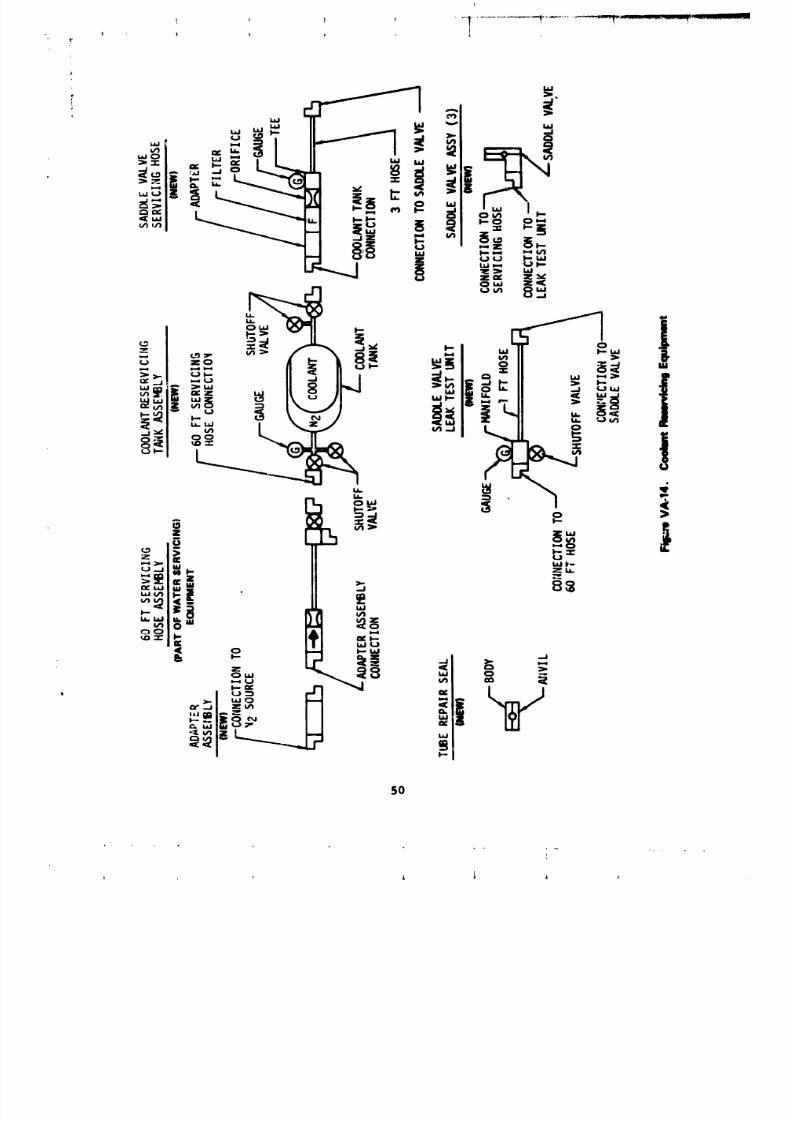
8/8/2019 MSFC Skylab Structures and Mechanical Systems Mission Evaluation
http://slidepdf.com/reader/full/msfc-skylab-structures-and-mechanical-systems-mission-evaluation 67/348
50
• - . k
8/8/2019 MSFC Skylab Structures and Mechanical Systems Mission Evaluation
http://slidepdf.com/reader/full/msfc-skylab-structures-and-mechanical-systems-mission-evaluation 68/348
Coolant servicing was accomplished by: (1) piercing
the primary coolant llne by turning the saddle valve stem until the stem
bottomed on saddle valve body, then retracting the stem to stop, (2)
opening the coolant supply valve on the reservicing tank to establish
flow into the primary loop, (3) closing the coolant supply valve on
the tank module after the primary loop was perviced to the desired level
(as indicated by the pressure gage on the 3-it servicing hose), (4)
turning the saddle valve stem until the |tea bottomed on saddle valve body,
and (5) disconnecting the service hoses.
Piece parts of the coolant reservlcing equipment were
primarily qualified by similarity to like equipment used in other airlock
applications. The tank was adapted from a coummnd module fuel tank.
The saddle valve was developed by NASA. The total assembly was integrated,
tested, and verified at MDAC-E. Verification included successful ground
reservicing of the Skylab ECS/TCS test unit and the backup alrlock coolant
systems.
In-fliKht servicing began on the fourth day of the third
manned phase at 2100 GMT, with removal of primary coolant line
insulation at the caSin heat exchanger module. The servicing
procedure progressed smoothly through attachment of the saddle valve
(without penetration) and pressurization of the leak test hose with the
35 psi GN2 from the workshop panel 500. The purpose of the leak checkprocedure was to verify that the saddle valve was not leaking prior to
penetration. The leak check procedure involved pressurizing the
saddle valve and leak check hose to a pressure greater that 30 psig,
closing the supply valve in the 60-ft water servicing hose, and me_-
itorin s for _0 min. If the pressure decay was less than 2 psi,
the servicing w=s to proceed. However, the leak test hose gage !nulcate,tan initial pressure of 33 psi and 35 min later 30.5 psi. After an
additional 20 min, the pressure was down to 25 psi. Thus, a leakwas indicated in the saddle valve or the leak check hose. To determine
the location of leak, the crew was instructed to disconnect the leak
check hose fror the saddle valve and repressurize the leak check
hose. The leak check hose alone showed a pressure drop of 2 psi in20 min and 2.5 psi in 27 min, thus indicating the leak was in
the leak check hose. The crew was then instructed to disconnect the leak
check hose from the servicing hose and to connect the coolant servicing
tank and the coolant servicing hose. The coolant valves were then opened
to supply coolant to the saddle valve under pressure prior to piercing
the coolant line. No coolant leakage was observed; the primary coolant
line was then pierced and the servicing proceeded. On the f_fth day
of the third manned phase, at 0042 G_r, tilS_it17 indicated • primary
loop coolant pressure of 27.2 or 22.2 psi S. Servicing was completed
with no leakage at the saddle valve. Pump B was activated and obtained65 paid across the pump. The crew also activated pump C for a two-pump
operation for 5 min. All telemetry data indicated normal readings.
51
1
8/8/2019 MSFC Skylab Structures and Mechanical Systems Mission Evaluation
http://slidepdf.com/reader/full/msfc-skylab-structures-and-mechanical-systems-mission-evaluation 69/348
At 0349 GHT, the pilot confirmed coolant servicing was complete with
saddle valve cover in place and all servt_in$ hoses stowed. The cool_nttank was placed on the mass measuring device and it was determined
that 7.7 lb of coolant had been added to the primary coolant system,
The reservlclng of the primary loo 9 permitted return
to the two loop operation of tht coolant system durln$ the periods of
hish beta angles and extravehicular activity (hlsh heat load periods).
Conclusions: Thermal control valves were designed to
close tolerances. It is recoumended that future applications of this
type use the sreatL_st possible tolerances commensurate with effective
operation. Aloo, future applications should provi filters upstreaL
of movins parts in fluid systems to minimize potential contamination.
The exact cause of the primary L,d secondary
coolant loep leakase may never be established. Th,- is evidence tha:
the leak could both be inside the pressure si_ell an_ outside the pressure
shell. Durlns the period followln8 deacti_ation of the loop. the pressurein the loop fell below (2.5 to 3.7 psia) and remained below cabin
pressure. This would indicate that the leek in the primary loop
was external to the cabin. The premise that the leak was internal to
the cabin is enhanced by findink a trace of coolanol constituents In
the returned PPCO2 cartrldp. Ifa leak were interns, to the cabin.
the most likely location would be under the molecular sieve "A" cover,
based upon analysis of the returned cartridses.
The benefits obtained by the successful reservicinR cf
the primary coolant loop were to restore two-loop operation and redundancy
in the system. The v_lue of two-loop operation was illustrated durin$the period of hiih beta anEles, day 62 throush day 70 of the third
manned phase. The internal tempereture would have been excessive withoutt_o-loop operation.
The use of backup hardware and the ECS/TCS Skylab test
unit for simulations and testinE proved invaluable durin$ the dev©lopment
of the reservicln i kit.
c. Suit coollnR system. The dual suit cool_ng systems
consist of coolant reservoirs, pumps and motors, heat exchansers, an
EVA/IVA liquid ass separator, check valves, relief valves, and connectins
coolant lines. Functional relationships are shown in Pigure VA-I$.
The system is reeulred to be capable of transfsrrlnE 2,000 Btu/hour
from each of t _e two water loops to the at_lock coolant system. Pressuredrop from components can not exceed 12 psid at a water coolant flow rate
of 250 lb/hr per loop. The coolant flow rate at the suit umbilical isrequired to be 200 lb/hr minimum per loop. Cooling is resuleted by
adJustln8 the flow rate of temperature controlled water throu6h each
liquid cooled sarment usin8 a flow diverter valve in the pressure controlunit,
52
i i I i j l
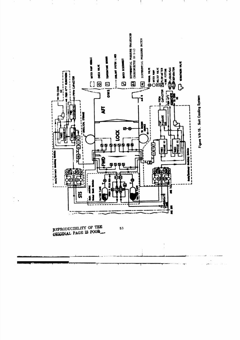
8/8/2019 MSFC Skylab Structures and Mechanical Systems Mission Evaluation
http://slidepdf.com/reader/full/msfc-skylab-structures-and-mechanical-systems-mission-evaluation 70/348
I I I !
BFPRODUOIBILITY OF _ 53
1
i

8/8/2019 MSFC Skylab Structures and Mechanical Systems Mission Evaluation
http://slidepdf.com/reader/full/msfc-skylab-structures-and-mechanical-systems-mission-evaluation 71/348
(I) Water pump. Each suit cooling system contains
two pumps in parallel for redundancy. Flow characteristics ranged from
220 to 280 ib/hr with a minimum delta pressure of ii.0 psid, with an input
voltage of 22 to 30 Vdc. Inlet pressure is 5.0 to 23.1 psig.
The water pump is a positive_displacement, rotary
vane, electrically powered pump assembly consisting of five subassemblies:
(i) pump, (2) relief valved (3) ac electric motor, (4) dc to ac inverter,
and (5) outer housing that encloses the entire assembly. Pumps can continue
to operate with the outlet line blocked because the internal relief valve
allows flow from the outlet back to the inlet side of the pump when the
outlet pressure builds up to the relief valve cracking pressure. Most
structural parts are made of corrosion-resistant steel and the bearings
are carbon journals. The entire unit is hermetically sealed by welding.
The motor stator and inverter are separated from the rotor and pump and
are sealed iu an inert atmosphere.
On the ground water pumps in the suit cooling system
experienced failure to start after a long off period. The problem was
traced to a nickel phosphate precipitate. Corrosion inhibitors
were changed to chromates and pump clearances were increased, resulting
in subsequent normal operation.
The modified water pump assembly was partially qualified
by similarity to a previously qualified unit used on a classified Air
Force research vehicle. Qualification by slmilarity included shock
to I00 g while not operating and to 15 g operating, acceleration to 7.8 g,
altitude to 200,000 ft, humidity at 95 percent minimum with temperature
cycling, and temperature extremes to 160 +5 °F and -35 °F. Airlock
qualification included vibration to 9.6 g rms and burst pressure at 144 psig.
Operating requirements were established at 3,610 active hours and
2,328 storage hours plus 20 operating cycles. Demonstrated capability
included 2,500 hr operating time and i00 cycles. This item was also
included in the 8-month endurance test. Acceptance testing of flight
type articles included proof pressure to 72 psig and leakage not to
exceed 1.5 x 10⁻⁵ ib/hr water at operating pressure. Operation during
the Skylab mission was adequate,
(2) EVA/IVA liquid gas separator. These units provide
a means of removing free gas from the suit cooling systems and also
act as a particulate filter. The flow requirement is 200 to 350 ib/hr of
coolant with 20 sec/mln gas wlth an allowed pressure drop of 1.25 psid.
Gas removal efficiency was 95 percent of 20 sec/min £nfluent free gas
at normal coolant flow while the gas discharge pressure was 0.5 to 6.2 psi
below inlet water pressure.
54
i
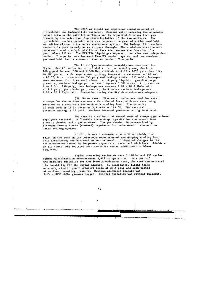
8/8/2019 MSFC Skylab Structures and Mechanical Systems Mission Evaluation
http://slidepdf.com/reader/full/msfc-skylab-structures-and-mechanical-systems-mission-evaluation 72/348
The EVA/IVA liquid gas separator contains parallel
hydrophobic and hydrophillic surfaces. Coolant water entering the separator
passes between the parallel surfaces and is separated from any free gas
present by the selective flow characteristics of the two surfaces. The
hydrophobic surface permits only gas to pass to a gas collection manifold
and ultimately on to the water condensate system. The hydrophillic surfa_:e
essentially permits only water to pass through. The stainless steel screen
construction of the hydrophylllc surface also serves the function of a
particulate filter. The EVA/IVA liquid gas separator contains two independent
coolant flow paths, one for each EVA/IVA coolant system, and one overboard
gas manifold that is common to the two coolant flow paths.
The liquid/gas separator assembly was developed for
Skylab. Qualification tests included vibration to 6.0 g ru_ shock to
180 g peak between 500 and 2,000 Hz, altitude to 1.93 x lO -_ psia, humidity
to i00 percent with temperature cycling, temperature extremes to 120 and
-140 OF, burst pressure to 350 psig and leakage tests. Allowable leakages
were measured for three conditions: at 14 psig liquid to gas dischargepressure, maximum leakage per coolant loop was 0.001 scc/m. At pressures
from 9.3 to 140 psig, case leakage maximum was 2.98 x 10 -5 lb/hr air.
At 9.2 psig, gas discharge pressure, check valve maximum leakage was
2.98 x 10⁻⁵ Ib/hr air. Operation during the Skylab mission was adequate.
(3) Water tank. Five water tanks are used for water
storage for the various systems within the airlock, with one tank being
required as a reservoir for each suit cooling loop. The capacity
of each tank is 16 Ib water at 5.5 psia at i15 °F. The external
pressure rating is 15 psid. Maximum internal pressure rating is 6 ps_d.
The tank is a cylindrical vessel made of epoxy-polyurethane
copolymer material. A flexible Viton diaphragm divides the vessel into
a water chamber and a gas chamber. The gas chamber is pressurized by
nitrogen from a 5 psia (nominal) regulator for tanks used in the various
water cooling systems.
At KSC, it was discovered that a Vlton bladder had
split in the tank in the telescope mount control and display cooling loop.
This discrepancy was believed to be the result of physical changes in the
Viton material caused by long-term exposure to water and additives. Bladders
in all tanks were replaced with new units and no additional problems
occurred.
Skylab operating estimates were 3_'10 hr and 150 cycles.
Gemini qualification demonstrated 3,949 hr operation. .q a part of
the hardware installed for the 8-month endurance test, the tank demonstratedits capability for the Skylab mission. At acceptance, flight tanks
were subjected to proof pressure tests at 28.5 psig and leak tested
at maximum operating pressure. Maximum allowable leakage was
3.15 x 10⁻⁵ ib/hr gaseous oxygen. Oribtal operation was without incident.
55
Q
i

8/8/2019 MSFC Skylab Structures and Mechanical Systems Mission Evaluation
http://slidepdf.com/reader/full/msfc-skylab-structures-and-mechanical-systems-mission-evaluation 73/348
I ! '
d. Telescope mount control and display console/EREP coolant
system. The telescope mount control and dlsplay console/EREP coolant system
is used for temperature control of the telescope mount control and display
panel and earth observation equipment. The cooling system, FigureVA-16, consists of a telescope mount tank module located in the airlock
structural transition section and a telescope mount water pump module
located exterior to the structural transition section. The telescope
mount tank module contains a water tank, filter D and filter bypass relief
alve. The telescope mount water pump module contains three parallel
plumbed positive displacement rotary vane water pumps and a ground cooling
type heat exchanger interfacing with the _R_S-602 coolant loops. Each
pump has an integral bypass relief valve, a differentlal pressure trans-
ducer for telemetry, and an outlet check valve. A flow transducer upstream
of the pu_ap module inlet provides telemetry measurement of system
flow. The single wrier loop is capable of removing 1,335 Btu/hr from
the docking adapter load and 102 Btu/hr from the operating pump. The
system delivers water to the docking adapter at a temperature between
40 and 75 °F a* a flow rate of 220 Zb/hr minimum. The ,maximum water
delivery pressure is limited to 37.2 psia by a relief valve. Location
of the heat exchanger in the airlock coolant loop is downstream of the tape
recorder cold plates to avoid impacting atmosphere conditioning and suit
cooling module performance.
The requirement to remove 98 percent of contaminants
i0 microns or larger and all particles above 25 microns from this system
i_ accomplished with a filter assembly (Figure VA-17) consisting of
a head, bowl, and filter element. The unit has particulate capacity
of 1 g/gal/min. The head provides inlet and outlet ports in straight-
through alignment, three nonsymmetrical mounting bosses, and a threaded
opening for attaching the cylindrical bowl. The bowl hclds the filter
element in place in the head. Water enters the inlet port on the headand flows into the bowl. The water passes from the periphery of the bowl
through the filter element and center support core to the outer port.The filter element is made of sintered stainless steel mesh. All other
parts are stainless steel except for a Viton O-r,., between the bowl
and the head.
The water filter was partially qualified by similarity
to porous fllters used by The Boeing Company. The airlock filter is rated
at 60 psi water using Viton A O_ings. Qualification by similarity
was limited to a low temperature at -65 eF. Skylab qualification included
a fluff compatibility test in which the filter was submerged for 90 days
in water that was nominally between 60 and 80 °F. A part of this test
increased the temperature to 160 QF for 72 hr. A particulate capacity
test, vibration co 7.0 g rms and burst pressure to 240 psia at 70 +i0 °F
were also conducted. Estimated operating requirements were 3D610 hr.
Capability for the Skylab mission was demonstrated in the 8-month
endurance test. Acceptance testing of flight type articles included
56
I 1 '
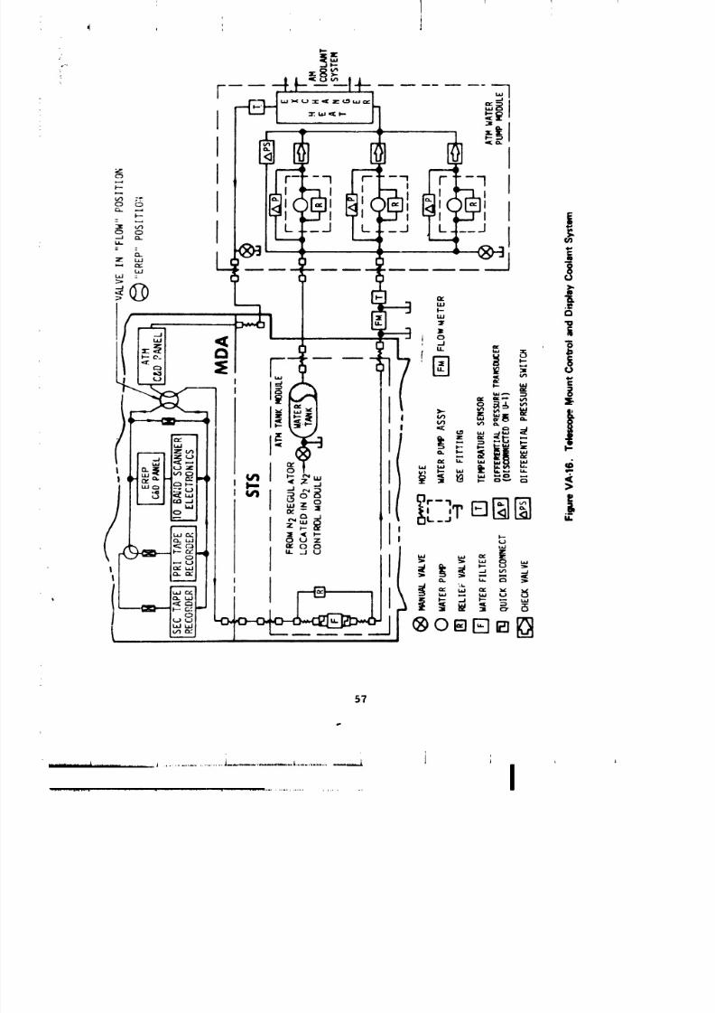
8/8/2019 MSFC Skylab Structures and Mechanical Systems Mission Evaluation
http://slidepdf.com/reader/full/msfc-skylab-structures-and-mechanical-systems-mission-evaluation 74/348
8/8/2019 MSFC Skylab Structures and Mechanical Systems Mission Evaluation
http://slidepdf.com/reader/full/msfc-skylab-structures-and-mechanical-systems-mission-evaluation 75/348
] 1 ! 1 1 1J
[STAIN s'r _'_
IAISI 300 SERIEt =:.:: ,__
c1
IN _
OUT
ELEMENT PREVENTSREVERSE ASS'Y
J
5.8 -3 ASSY.
MAXINTERNAL SUPPORT
CORE (STAINLESS STEEL) STAIN, STEELAISI 300 ....SERIES
FILTER ELEMENT,
STAIN. STEELlSl 300 SERIES
I
iLEU r " !
STEEL PRING
1,000 DIA 1_" MIN. "-
MAX. CLEARANCESECTION AA FOR REMOVAL OF
ELEMENT • BOWL
Figure VA-17. Water Filter Amembiy
58
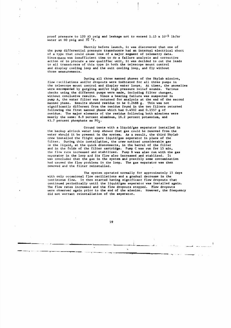
8/8/2019 MSFC Skylab Structures and Mechanical Systems Mission Evaluation
http://slidepdf.com/reader/full/msfc-skylab-structures-and-mechanical-systems-mission-evaluation 76/348
proof pressure to 120 +5 psig and leakage not to exceed 1.15 x 10⁻⁵ ib/hr
water at 60 pslg and 7_ °F.
Shortly before launch, it was discovered that one ofthe pump differential pressure transducers had an internal electrical short
of a type that could cause loss of a major segment of telemetry data.
Since there was insufficient time to do a failure analysis and corrective
action or to procure a new qualifle4 unit, it was decided to cut the leads
to all transducers of this type in both the telescope mount control
and display cooling loop and the suit cooling loop, and fly without
those measurements.
During all three manned phases of the Skylab mission,
flow cscillations and/or dropouts were indicated for all three pumps in
the telescope mount control and display water loops. At times, the anomalies
were aocompanJed by gurgling and/or high pressure relief sounds. Various
checks using the different pumps were made, including filter changes,
without conclusive results. Since a bearing failure was suspected in
pump A, the water filter was returned for analysis at the end of the second
manned phase. Results showed residue to be 0.2688 g. This was not
significantly different from the residue found in the two filters returned
following the first manned phase which had 0.4502 and 0.1557 g of
residue. The major elements of the residue following both missions were
nearly the same: 8.9 percent aluminum, 16.2 percent potassium, and
43.7 percent phosphate as PO 2.
Ground tests with a liquid/gas separator installed in
the backup airlock water loop showed that gas could be removed from the
water should it be present in the system. As a result, the third Skylab
crew installed the fliBht spare liquld/gas separator in place of the
filter. During this installation, tile crew noticed considerable gas
in the ]iquid, at the quick disconnects, in the barrel of the filter
and in the folds of the filter cartridge. Pump C was run for 15 min,
the flow rate increased and stabilized. Pump B was also run with the gas
separator in the loop and its flow also increased _d stablized. It
was concluded that the gas in the system and possibly some contamination
had caused the flow problems in the loop. The gas separator was then
removed and the filter reinstalled.
The system operated normally for approximately 15 days
with only occasional flow oscillations and a gradual decrease in the
continuous flow. It then started having significant flow dropouts that
continued periodically until the llquld/gas separator was ins_alled again.
The flow rates increased and the flow dropouts stopped. Flow dropouts
were observed again prior to the end of the mission. However, the frequency
did not warrant reinstallatlon of the separator.
59
i,. _........ __ .........................._..... ./ ........ *............ .,.............
R_q_ H_ IRa,I
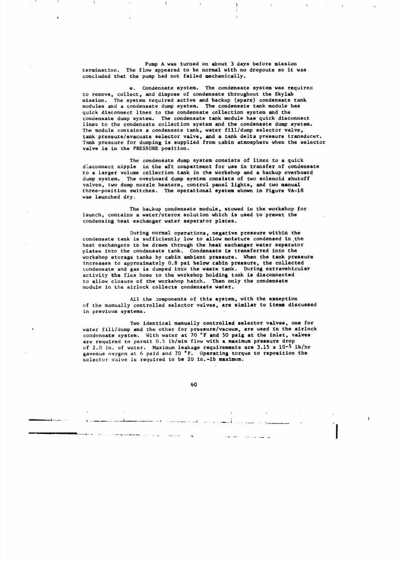
8/8/2019 MSFC Skylab Structures and Mechanical Systems Mission Evaluation
http://slidepdf.com/reader/full/msfc-skylab-structures-and-mechanical-systems-mission-evaluation 77/348
l l l i ' l ,
l
Pump A was turned on about 3 days before mission
termination. The flow appeared to be normal with no dropouts so it was
concluded that the pump had not failed mechanically.
e. Condensate system, The condensate system was requireG
to remove, collect, and dispose of condensate throughout the Skylab
mission. The system required active and backup (spare) condensate tank
modules and a condensate dump system. The condensate tank module has
quick disconnect lines to the condensate collection system and the
condensate dump system. The condensate tank module has quick disconnect
lines to the condensate collection system and the condensate dump system.
The module contains a condensate tank, water fill/dump selector valve,
tank pressure/evacuate selector valve, and a tank delta pressure transducer.
Tank pressure for dumping is supplied from cabin atmosphere when the selector
valve is in the PRESSURE position.
The condensate dump system consists of lines to a quick
disconnect nipple in the aft compartment for use in transfer of condensate
to a larger volume collection tank in the workshop and a backup overboard
dump system. The overboard dump system consists of two solenoid shutoff
valves, two dump nozzle heaters, control panel lights, and two manual
three-positlon switches. The operational system shown in Figure VA-18
was launched dry.
The backup condensate module, stowed in the workshop for
launch, contains a water/sterox solution which is used to prewet the
condensing heat exchanger water separator plates.
During normal operations, negative pressure within the
condensate tank is sufficiently low to allow moisture condensed in.the
heat exchangers to be drawn through the heat exchanger water separatorplates into the condensate tank. Condensate is transferred into the
workshop storage tanks by cabin ambient pressure. When the tank pressure
increases to approximately 0.8 psi below cabin pressure, the collected
condensate and gas is dumped into the waste tank. _ring extravehicular
activity the flex hose to the workshop holding tank is disconnected
to allow closure of the workshop hatch. Then only the condensatemodule in the alrlock collects condensate water.
All the _omponents of this system, with the exception
of the manually controlled selector valves, are similar to items discussed
in previous systems.
Two identical manually controlled selector valves, one for
water fill/dump and the other for pressure/vacuum, are used in the airlockcondensate system. With water at 70 °F and 50 psig at the inlet, valves
are required to permit 0.5 lb/mln flow with a maximum pressure drop
of 2.0 In. of water. Maxlmum leakage requirements are 3.15 x 10⁻⁵ Ib/hr
gaseous oxygen at 6 psld and 70 °F. Operating torque to reposition the
selector valve Is required to be 20 in.-Ib maximum.
6O
i
I
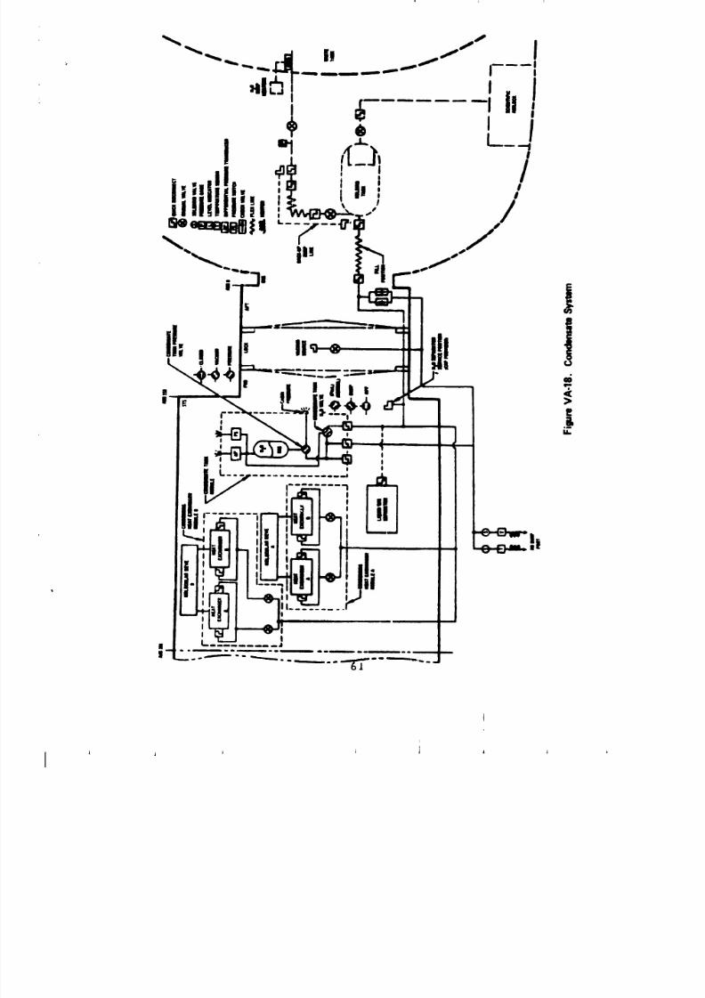
8/8/2019 MSFC Skylab Structures and Mechanical Systems Mission Evaluation
http://slidepdf.com/reader/full/msfc-skylab-structures-and-mechanical-systems-mission-evaluation 78/348j i i J
L

8/8/2019 MSFC Skylab Structures and Mechanical Systems Mission Evaluation
http://slidepdf.com/reader/full/msfc-skylab-structures-and-mechanical-systems-mission-evaluation 79/348
L
The water dump valve is a three-way position selector
valve that contains two inlet flow porte and a common outlet flow passage.
The valve consists of a hollow rotating shaft sealed at one end with two
offset ports drilled 120" apart using 0-rings for sealing against leakage.
A flat portion is machined on the valve stem for indexing and mating with
a control handle. A shaft rotation of 120" is required to select
flow from one port or the other. A midstroke off poeitlon blocks flow
from either inlet.
The valve was qualified for Gemini and flew on flights 2
through 12. Gemini qualification included buret pressure to 200 peig.
Because of Skylab operational estimates of 3,610 hr and 190 cycles, the
valve was qualified to a demonstrated life of 3,966 hr and 1,000
cycles. At acceptance, each valve was tested for leakage (3.15 x 10 -5 ib/hr
02 max) and proof pressure tested to 100 peig. One unit was subjected to
a 90-day corrosion test to support Skylab requirements.
During the Skylab mission the condensate removal capability
of the condensate system performed to epeclflcatlon. However, leaks in
the system caused many more dumps than had been planned. During the
second manned phase, when the leak persisted for 32 days, the system
was dumped each day. The system performed other functions successully,
such a_ servicing/deservlcin 8 of life supp=rt umbilicals/pressure
control units, servicing heat exchanger separator plates, and removing
water from the command and eervlce module water tank.
During the first manned phase, when the workshop holding
taz_k was disconnected from the condensate system for extravehicular
activities, the _ystem delta pressure dropped rapidly. Since the pressure
did not decrease rapidly with the holding tank connected, it was concluded
that a leak existed on the gas side of the airlock system.
During the second manned phase, water separator plate servicing,
the condensate delta pressure again began to decrease. The leak was
believed to be in one of the gas side quick disconnects. However, the
leak stopped and dil not appear again until late in the third manned
phase (mission day 80) when the liquid gas separator quick disconnect
was disconnected for extravehicular activities. After attempts to stop
the leak with universal sealant, a cap launched on the third manned phase
speclf[cally for this purpose was installed on the hose side of the liquid/
gas separator 8as connector. No further leakage was observed.
On mission day 34s during the second manned phase, the waste
tank management system failed to completely dump the workshop condensateholding tank. The dump probe was coneldered to have frozen. A 35 psi
hot water dump cleared the probe with the bus #2 heater on. However,
a try at dumping tile condensate tank failed. Another 35 psi hot water dump
62

8/8/2019 MSFC Skylab Structures and Mechanical Systems Mission Evaluation
http://slidepdf.com/reader/full/msfc-skylab-structures-and-mechanical-systems-mission-evaluation 80/348
using bus #i h_ater cleared the line. Subsequent holding t_nk dumps were
successfully performed but were slower than they should have been.
On mission day 36, a holding tank dump was unsuccessful. The water dump
probe assembly was replaced. No further problems were encountered.
f. Quick disconnects. Quick disconnects are used in H20 ,
C02, GN2, and GO2 systems and are available in either I/8-, 1/4-, or
3/8-in. size. Their primary use is to provide a quick means of removing or
connecting an environmental control system llne. The I/8-in. quick
disconnects are used either in the H20 system or for CO2 sensing and aremade of 303 stainless steel with Buna N seals for the H20 use, and 316
stainless steel with silicone compound i1715 seals for CO2 sensing.
The 3/8-in. quick disconnects are used in the H20 system and are made of
316 stainless steel with Buns N O-rings. The I/4-in. quick disconnects
are used in the GO2 and GN2 systems and are made of 316 stainless steel
with hatch tested Viton A O-rings for the GO2 and silicone Parker
compound 11715 for the GN2.
The quick disconnects assembly consists of a valved nipple
assembly, a valved coupler assembly, and a pressure cap assembly. Mating
fittings are held together by a sprlng-loaded ball-lock mechanism. When
disconnected, valves in the nipple and the coupler are held in closed
position by both spring pressure and system pressure.
The quick disconnects were developed for use on the Gemini
program, but were never used. Skylab qualification included vibration,
humidity, temperature, and bust pressure. Life test was 1,000 connect/
disconnect cycles in addition to the 8-month endurance test. During
initial receipt of components, recleaning was done that late_ caused leaks
because of the loss of lubricant on O-rings. O-rings were relubricated,
stopping all leaks. Also, during early testing, some quick disconnects
experienced negative pressure leaks that were traceable to cut or damaged
O-rings or contamination on O-rings.
During the process of changing the filter in the telescope
mount control and display water loop, the first Skylab crew reported a
slight spillage of water (approximately 2 to 4 oz) from one of the water
quick disconnects. The crew sald during the post-flight debriefing that
the internal plunger of the quick disconnect did not close fully when it
was disconnected. It was reconnected and disconnected again with _loapparentteakage. It is believed that the leakage was a momentary malfunction that
was cleared by the connect/disconnect procedure used by the crew.
63

8/8/2019 MSFC Skylab Structures and Mechanical Systems Mission Evaluation
http://slidepdf.com/reader/full/msfc-skylab-structures-and-mechanical-systems-mission-evaluation 81/348
I I
B. Fixed Airlock Shroud
The fixed airlock shroud is required to provide continuity of
the external environmental protection from the payload shroud to the in-
strument unit. Structurally the fixed airlock shroud supports the combined
alrlock docking adapter, the payload shroud, the teiescope mount deploy-
ment assembly, and six high pressure oxygen bottles. Concentrated loads
generated at these attachments are distributed by the fixed airlock shroud
to reduce peaking loads at the instrumeu_ _it interface. A ground umbilical
was required to provide electrical connections for telescope mount prelaunch
checkout, payload shroud purge gas, docking adapter insulation purge gas,
telescope mount purge gas. and ground cooling of the airiock coolant
system. The fixed airlock shroud was designed to a safety factor of 2.0
times the predicted loads for all unnmnned phases of the mission and
3.0 times the predicted loads for all numned phases to preclude requirementsfor static test.
The fixed alrlock shroud is a rlng-sti_fened, thick-sklnned cylinderapproximately 80 in. in height, 260 in. in diameter, and configured
as shown in Figure V_-l. Intercostale distribute concentrated loads
introducted by the deployment assembly, alrlock, and oxygen support points.Two doors are on the fixed airlock shrouds one for access to the
fixed airlock shroud interior and the airlock extravehicular activity
hatch during ground operations, and one for access to ground umbilical
connectors. Four antennas, two deployable discones, and two UHF antennasare mounted on the fixed alrlock shroud. The fixed alrlock shroud
structure also contains extravehicular activity support equipment:
Ingress/e_ress handrails, work platforms, film cassette tree supports,
film transfer boom also celled Tubular Extendible Eleaent (TEE), a
TEE hook stowage box, and lights.
Ground verification of the static load capability was conducted
by analyses to verify the design safety factors. The vibroacoustic test
at JSC verified the capability of the fixed airlock shroud to withstand
the launch and boost vibration and acoustic noise levels. Figure VE-6
p:'esents the results of the JSC tests. The umbilical separation and
_utomatic umbilical door closure were verified by testing at MSFC using
a flight-type umbilical and door and a swing arm simulator.
The first crew reported in crew debriefing that the fixed alrlock
shroud structure and all shroud mounted equipment appeared in excellent
conditlon with no evidence of buckling or breaking. Thus, it is obvious
that the fixed airlock shroud performed as expected and the practice
of designing such a configuration to a factor of two times predicted
loads without test verification is acceptable when weight is notcritical. Photographs of the first mkmanned pha_e llft-off show that
the fixed airlock shroud umbilical door had closed properly.
64
iI A i i

8/8/2019 MSFC Skylab Structures and Mechanical Systems Mission Evaluation
http://slidepdf.com/reader/full/msfc-skylab-structures-and-mechanical-systems-mission-evaluation 82/348
8/8/2019 MSFC Skylab Structures and Mechanical Systems Mission Evaluation
http://slidepdf.com/reader/full/msfc-skylab-structures-and-mechanical-systems-mission-evaluation 83/348
C. Telescope Mount
1. General Description. The telescope moun. structural/mechanical
_ystem provides for the housing of the solar astronomy experiments with
their support equipment, includln8 their pointing control and thermal
control systems. It also provides for the mounting of Saturn Workshop
attitude control equipment and the telescope mount electrical power system.
The structural/mechanical system, Figure VCI-I, consists of _he
telescope mount rack, experiment canister, rack/canlster interface hard-
ware, the solar array deployment mechunlsm, aperacure doors, film retrieval
doors, thermal control system hardware, ordnance systems, and extravehicular
activity hardware, The telescope mount assembly is attached to the
deployment assembl_ through risidlz£n8 attach fittings at the rack base.
This interface did not provide load carrying capability during the pre-
launch aztd launch p ases. For these phases, load transfer into the
vehicle structure was provided through the telescope m_unt/payl_adsi,_oud interface.
2 Telescope Mount Structural Systems. Figure VC2-1 shows the
basic telescope mount structural system.
The rack is the main structural assembl T of the telescope mount
and consists of octagonally shaped upper, lower, and solar array support
rings. These rinas are each comprised of an inner and outer cap connected
by webs and web s=iffeners. A longitudinal load path between rings is
provided by vertical beams at each corner of the octagoltal support rings.
OutrLggcr fittings at eacr_ octagonal corner connect to the outrigger tubular
members that form four pyramid shaped trusses, and the entire telescope
mount is supported in the launch configuration by interfacing with the
p_yload shroud/telescope mount support fxttlngs where the truss members
converge.
The rack was originally designed as an _pen trt,ss s_ructu_e. As
the program e_olved and as telescope requirements changed, the truss
arzangement became difficult to adapt to ne_ requirements. Primarily
the difficulties fell into two categories: (1) lnsu_ficiettt _ouating
space for b_ack boxes (quarter panels were added to three bays of the
rack and additional panels to the upper ring surface), and (2) thermal
requtr,ments imposed severe restrictions to avoid radiatie_ to other
components. The adaptability of tlte rack structure to provide thermal
_hields or to accommodate shi£tlng of components to more (avora_le thermal
zones was q,_ite limited. The structure was modified to incorporate non-
structurai thermal panels it_ addition to the original try, as members.
Sumc early difficulty was also experienced $- pzovidins a structure
that was adaptable to continually changing equipment locations.
6;J
t
t

8/8/2019 MSFC Skylab Structures and Mechanical Systems Mission Evaluation
http://slidepdf.com/reader/full/msfc-skylab-structures-and-mechanical-systems-mission-evaluation 84/348
_-- FILM flETRIEVAL
(\
RE
DOORS1101
SUN END VIEW
C_,TROL SYSTEMHARDWARE
FILM RETRIEVAL DOORS (S)
SOLAR CANISTER ,,.DE
CANISTER
PAYLOAD SHROUD
ATTACH FITTINGS (4)
DEPLOYMENT ASS'Y
ATTACH FITTINGS (4)RACK
Figure VCI-1. Telescope Mount Assembl_
IJ
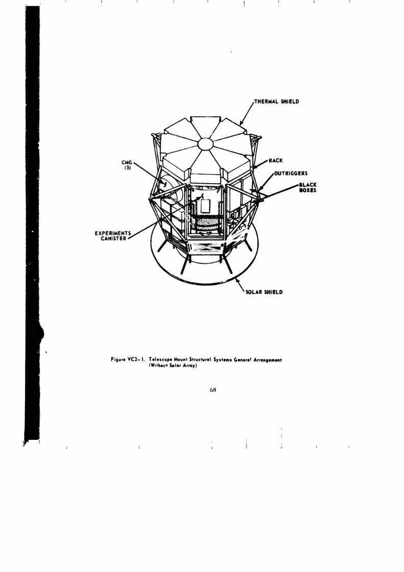
8/8/2019 MSFC Skylab Structures and Mechanical Systems Mission Evaluation
http://slidepdf.com/reader/full/msfc-skylab-structures-and-mechanical-systems-mission-evaluation 85/348
,THERMAL SHIELD
CMG RACK(3)
,OUTRIGGERS
ACKlOXES
EXPERIMENTSCANISTER
SOLAR SHIELD
I
Figure VC2-1. Telescope MountStructural SystemsC,enoro Arrangement(Withovt SolarArray)
68
I .... I 1 i i J

8/8/2019 MSFC Skylab Structures and Mechanical Systems Mission Evaluation
http://slidepdf.com/reader/full/msfc-skylab-structures-and-mechanical-systems-mission-evaluation 86/348
The original stiffened sheet metal design proved to be inflexible;
, _:onsequent]y, a honeycomb panel design was adapted. This allowed relocation
of panel inserts, thus accommodating new equipment mounting locations,
without redesign or scrapping of existing hardware.
One of the eight bays of the rack structure is left open to
permit access, both ground and extravehicular activity, to the
experiment package. Originally, it had been planned to maintain the
diagonal truss in this bay, but design it for extravehicular activity re-
moval. However, studies and analysis proved the rack strength to be
satisfactory for all flight conditions without the diagonal strut.
Consequently, the design incorporated only those provisions needed for
ground handling conditions and the diagonal strut was then removed in the
VAB after telescope mount stacking.
During the vibration testing of a full telescope mount assembly,
dynamic cross coupling of the rack structure was discovered (a
longintudinal excitation produced _ lateral response). As this was
very late in the program, a satisfactory hardware solution could not
be found. Consequently, the only remaining course of action was to reduce
the forcing function. This was accomplished by changing the S-IC engine
cutoff sequence fronl 1-4 to 1-2-2. The rack structure was designed to an
ultimate safety factor of 1.25 and a yield safety factor of i.i. The
rack was statically tested to seven flight load conditions and four
transportation conditions. Table VC2-1 shows these test conditions and
the design loads acting at the c.g. of the rack and experiment package.
The experiment canister consists of a spar with a girth ring in the
center, a ring on each end, and two canister halves to enclose the
experiments (teles,:opes) mounted on the spar (Figure VC2-2).
The spar is a cruciform structure made up of th, ee 1.0-1n. thick
aluminum plates. It serves as the structural support and optical bench
for the telescope mount experiments. Two inch diameter holes are dr_lled
throl,ghout the plates to minimize weight.
N,, flight instrumentation was available oi, the telescope mount
basic st ruct.,re to enable direct comparison with design values. From
other flight performance data such as vehicle acceleration, wind velocity,
an_l booster engine glmbal angles on the launch vehicle, the load during
flight at the rack and experiment package c._. wer6 calculated for two
conditions. These calculated values are compared to the design values in
the following tabulation.
69
i ] '
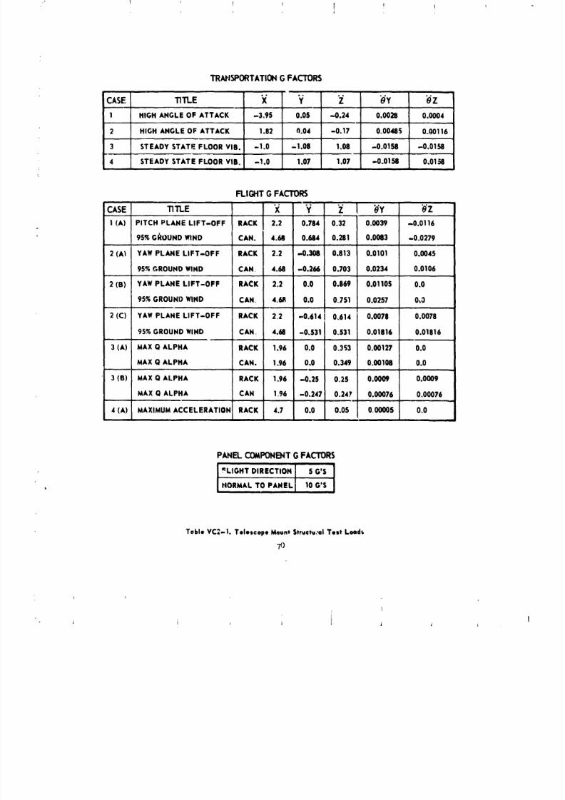
8/8/2019 MSFC Skylab Structures and Mechanical Systems Mission Evaluation
http://slidepdf.com/reader/full/msfc-skylab-structures-and-mechanical-systems-mission-evaluation 87/348
1 1 1 1 _ I
TRANSPORTATION O FACTORS
i i i ii i
CASE TITLE X Y "Z O"Y _Z
1 HIGH ANGLE OF ATTACK -3o95 0.05 -0.24 0.0028 0.0004
2 HIGH ANGLE OF ATTACK 1.82 11.04 -0.17 0°00485 0.00116
3 STEADY STATE FLOOR VIB. -!.0 -1.08 1.08 -0.0158 -0.0158• , L , ,
4 STEADY STATE FLOOR VIL -1.0 1.07 1.07 -0.0158 0.0158
FLIGHT G FACTORS
CASE TITLE "X "Y "Z I b'Y b'Z,. ,,,
1 (A) PITCH PLANE LIFT-OFF RACK 2.2 0.784 0°32 0.0039 -0o0116
95%GI_OUNDWIND CAN. 4.68 0.684 00281 0.0083 -0°0279
2 (A_I YAWPLANE LIFT-OFF RACK 2°2 -0.308 0.813 0.0101 0.0045
95%GROUNDWIND CAN 4.68 -0.266 0°703 0.0234 0.0106
2 (B) YAWPLANE LIFT-OFF RACK 2.2 0.0 0.869 0.0110S 0.0
95%GROUNDWIND CAN_ 4_6R 0.0 0_751 0.0257 0,.O
2 (C) YAWPLANE LIFT-OFF RACK 22 -0_614 I 0o614 0.0078 0.0078
95%GROUNDWIND CAN 4.68 -0.531 0.531 0.01816 0.01816
3 (A) MAXQ ALPHA RACK 1.96 0.0 0.353 0.00127 0.0
MAX Q ALPHA CAN. 1_96 0,0 0.349 0.00108 0.0
3 (B) MAX Q ALPHA RACK 1o96 -0.25 0.25 0.0009 0.0009
MAX Q ALPHA CAN 196 -0,247 0.247 0.00076 0.00076
4 (A) MAXIMUMACCELERATION RACK 4.7 0.0 0.05 0,00005 0o0
PANEL COMPONENT G FACTORS
_LIGHT DIRECTION 5 O'S
NORMAL TO PANEL 10G'S
Table VC_-l. TelescopeMountStructu:ulTest L(.Id_
I
iJ , l i _ j
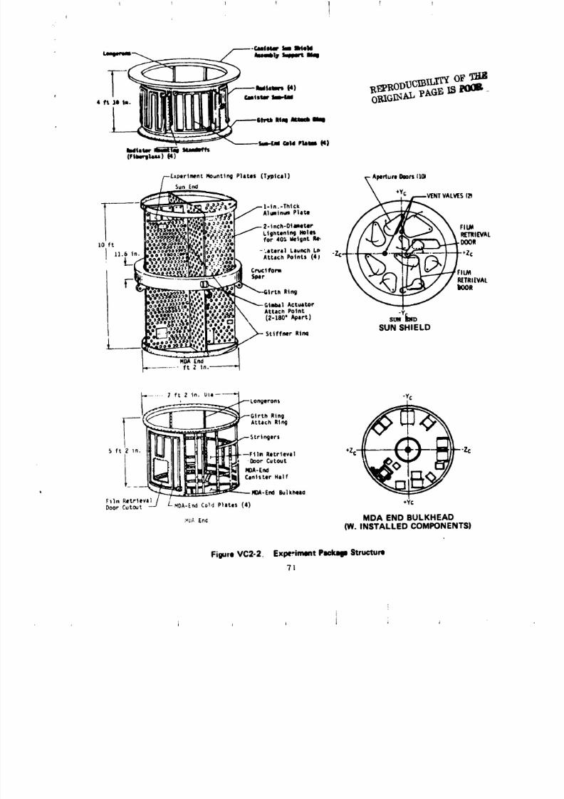
8/8/2019 MSFC Skylab Structures and Mechanical Systems Mission Evaluation
http://slidepdf.com/reader/full/msfc-skylab-structures-and-mechanical-systems-mission-evaluation 88/348
r
--Exper1ment Nounting P]lte$ (T_qHcIi) t-Aperture _lors (10)
;,;_o,-:- _._e._,ch.o4,,,t,, / /I \C'_ j\ \ F,UA' "_"_:"":"":'"'''" / /¢P7__'o ft I'_%'.;_(1[:;'.'.._,, forio_,,tl,t _ tWL
. EYAL
F _X-4I rtl_ Ring
_gt_] Aeratore,t I _)4Yl
£;__.'_["_t/[','.',.;i_ ', (z-eo'*_,.t) s_VfkNo
l_o_.r ,I'._'.'...'.._ SUN SHIELD
-._/ _ [na_'* ft 2 in. -----'-_
FigureVC2-2. ExperimentP_mkqleStructure
71
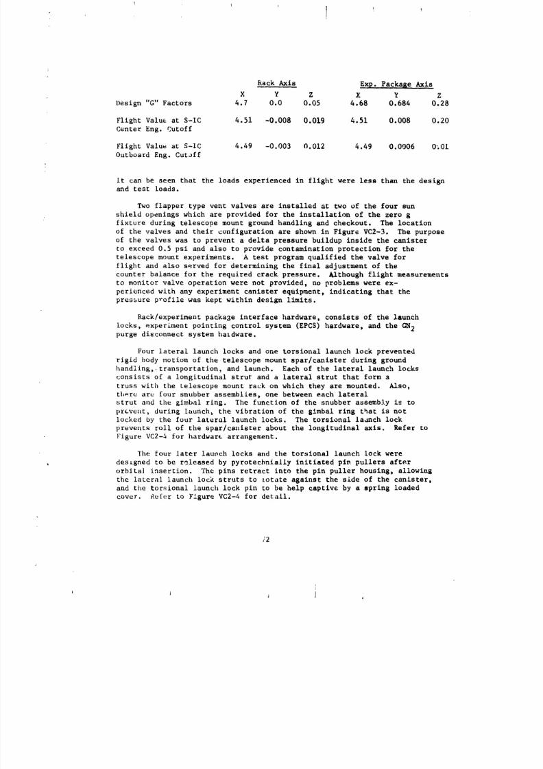
8/8/2019 MSFC Skylab Structures and Mechanical Systems Mission Evaluation
http://slidepdf.com/reader/full/msfc-skylab-structures-and-mechanical-systems-mission-evaluation 89/348
Rack Axis Exp. Package Axis
X Y Z X Y Z
Design "G" Factors 4.7 0.0 0.05 4.68 0.684 0.28
Flight Value at S-IC 4.51 -0.008 0.019 4.51 0.008 0.20
Center Eng. Cutoff
Flight Value at S-IC 4.49 -0.003 0.012 4.49 0.0006 0_01
Outboard Eng. Cutoff
it can be seen that the loads experienced in flight were less than the designand test loads.
Two flapper type vent valves are installed at two of the four sun
shield openings which are provided for the installation of the zero g
fixture during telescope mount ground handling and checkout. The location
of the valves and their configuration are shown in Figure VC2-3. The purposeof the valves was to prevent a delta pressure buildup inside the canister
to exceed 0.5 psi and also to provide contamination protection for the
telescope mount experiments. A test program qualified the valve for
flight and also served for determining the final adjustment of the
counter balance for the required crack pressure. Although flight measurements
to monitor valve operation were not provided, no problems were ex-
perienced with any experiment canister equlpment, indicating that the
pressure profile was kept within design limits.
Rack/experiment package interface hardware, consists of the launch
locks, experiment pointing control system (EPCS) hardware, and the GN2purge disconnect system hardware.
Four lateral launch locks and one torsional launch lock preventedrigid body motion of the telescope mount spar/canister during ground
handling, transportation, and launch. Each of the lateral launch locks
consists of a longitudinal strut and a lateral strut that form a
truss with the telescope mount rack on which they are mounted. Also,
there are four snubber assemblies, one between each lateral
strut and the gimbal ring. The function of the snubber assembly is to
prevellt,during launch_ the vibration of the gimbal ring that is not
locked by the four lateral launch locks. The torsional laanch lock
prevents roll of the spar/canister about the longitudinal axis. Refer to
Figure VC2-4 for hardware arrangement.
The four later launch locks and the torsiona] launch lock were
designed to be released by pyrotechnially initiated pin pullers after
orblta] insertion, The pins retract into the pin puller housing, allowing
the lateral launch lock struts to zotate against the side of the canister,
and the torsional launch lock pin to be help captive by a spring loaded
cover. Re[er to Figure VC2-4 for detail.
/2
i I J I
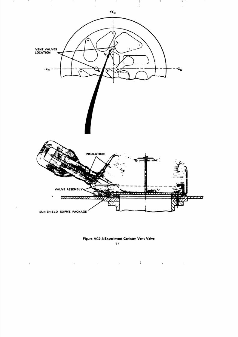
8/8/2019 MSFC Skylab Structures and Mechanical Systems Mission Evaluation
http://slidepdf.com/reader/full/msfc-skylab-structures-and-mechanical-systems-mission-evaluation 90/348
0
VENT VALVES fLOCATION
VALVE
SUNSHIELD-EXPMT. PACKAGE
FigureVC2-3ExperimentCanisterVent Valve
73
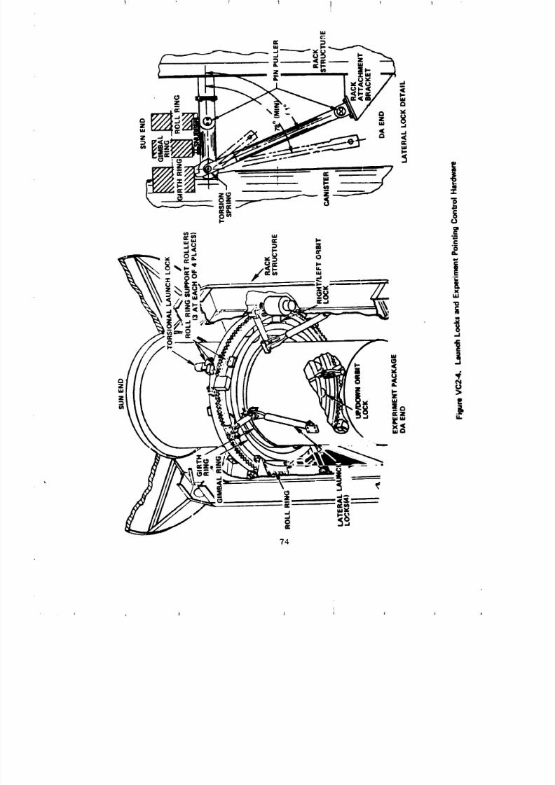
8/8/2019 MSFC Skylab Structures and Mechanical Systems Mission Evaluation
http://slidepdf.com/reader/full/msfc-skylab-structures-and-mechanical-systems-mission-evaluation 91/348
" !74
8/8/2019 MSFC Skylab Structures and Mechanical Systems Mission Evaluation
http://slidepdf.com/reader/full/msfc-skylab-structures-and-mechanical-systems-mission-evaluation 92/348
I!
The telescope mount launch lock release ordnance system shown
in Figure VC2-5, was completely redundant and consists of 2 EBW
detonators, 2 CDF manifolds, 2 CDF tees, 21 CDF assemblies, and 18
CDF pressure catridges. A schematic of these components is shown in
Figure VC2-6. An electrical signal was transmitted from an EBW firing
unit that initiated the EBW detonators and started the propagation train.
The propagation was transferred through the CDF manifolds D CDF tees, and
CDF assemblies to the CDF pressure cartidges that developed the pressure
to retract the nine pin puller pins, thereby, unlocking the canister from
the rack.
The EBW firing unit charge and trigger voltage measurement data are
not available for evaluation since telescope mount telemetry was not
activated at the time of this event. Also 0 there was no instrumentation
to indicate positively that the pin puller pins had retracted or that
the locks had released. Therefore, the first positive confirmation that
this system had functioned properly was by actual canister rotationduring initial activation.
To prevent contamination, the telescope mount experiment canister
was purged on the pad with gaseous nitrogen (GN2). A retractable fitting(disconnect coupling) carries this GN 2 from the telescope mount rack
to the canister. The ground support equipment line is disconnected
at the fixed airlock shroud prior to launch, but the retractable fittingbetween the rack and canister is not. The rack to _anister
fitting was released when the cre,"rotated the canister the first time
in orbit. A guide rail and roller prevents the spring loaded arm from
retracting before the male fitting is completely disengage@. To properly
disengage the purge fitting_ the canister must rotate at lowest speed in
a clockwise direction (1ooklng toward the sun end) {Figure VC2-7).
The mechanical system components (male and female disconnect coupling
with lead-in tubing component) conformed to the following qualification
and performance requirements: Operating pressure of 0 to 75 psig, leakage
not to exceed 50 scims, disconnect force not to exceed 15 Ib,
proof pressure of i]3 psig, and burst pressure of 188 psig.
Development and qualification tests were performed according to
S&E-ASTN-TMU (73-36) with vibration levels specified in memorandum
SbE-ASTN-TMV (73-26). Also, the retract mechanism was operated
successfully 1(}times under vacuum conditions after suhjection to the
launch environment. Iilltial canister roll and subsequent operation
confirms that the GN2 purge disconnect retracted also folded out of
the way against the rack.
75
i
i I I j
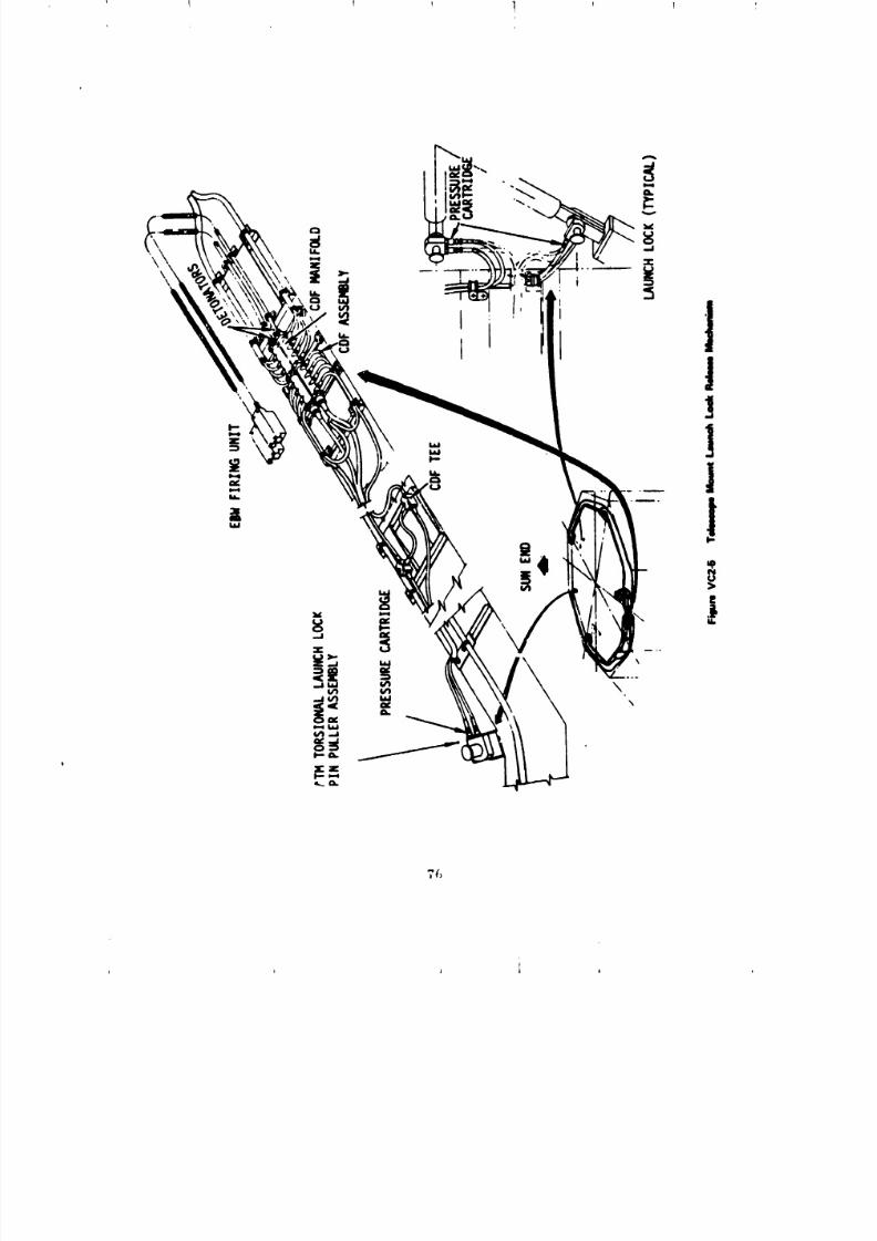
8/8/2019 MSFC Skylab Structures and Mechanical Systems Mission Evaluation
http://slidepdf.com/reader/full/msfc-skylab-structures-and-mechanical-systems-mission-evaluation 93/348

8/8/2019 MSFC Skylab Structures and Mechanical Systems Mission Evaluation
http://slidepdf.com/reader/full/msfc-skylab-structures-and-mechanical-systems-mission-evaluation 94/348
I I I 1 1 1I
t
J
l/'/ "" 'til" m"i i!_ -- Imi HT_TOll
=1-.......... LATIIIMI. LMLm_1_=------_l-4_POqI, N ......... |-V C,JIUPJIOI'IIN
_" . _" " "'t'"t"..... --crl_F ,,,,.f.......-,=u
>-.....I;:-----:_-L- "--i_ill, , _ I r"i..l i-z¢,_.=,..
L[-7-J-b_:---+u-.................. LJLTIRAI,F I b--....<U-L,-,i+,,,,
'_ .......... Ill IAWllilll
_.....y.,f...::::_====================VC_4 TiIN_ _ _ LLi RiI. OHMIM.
??
t I i i i A
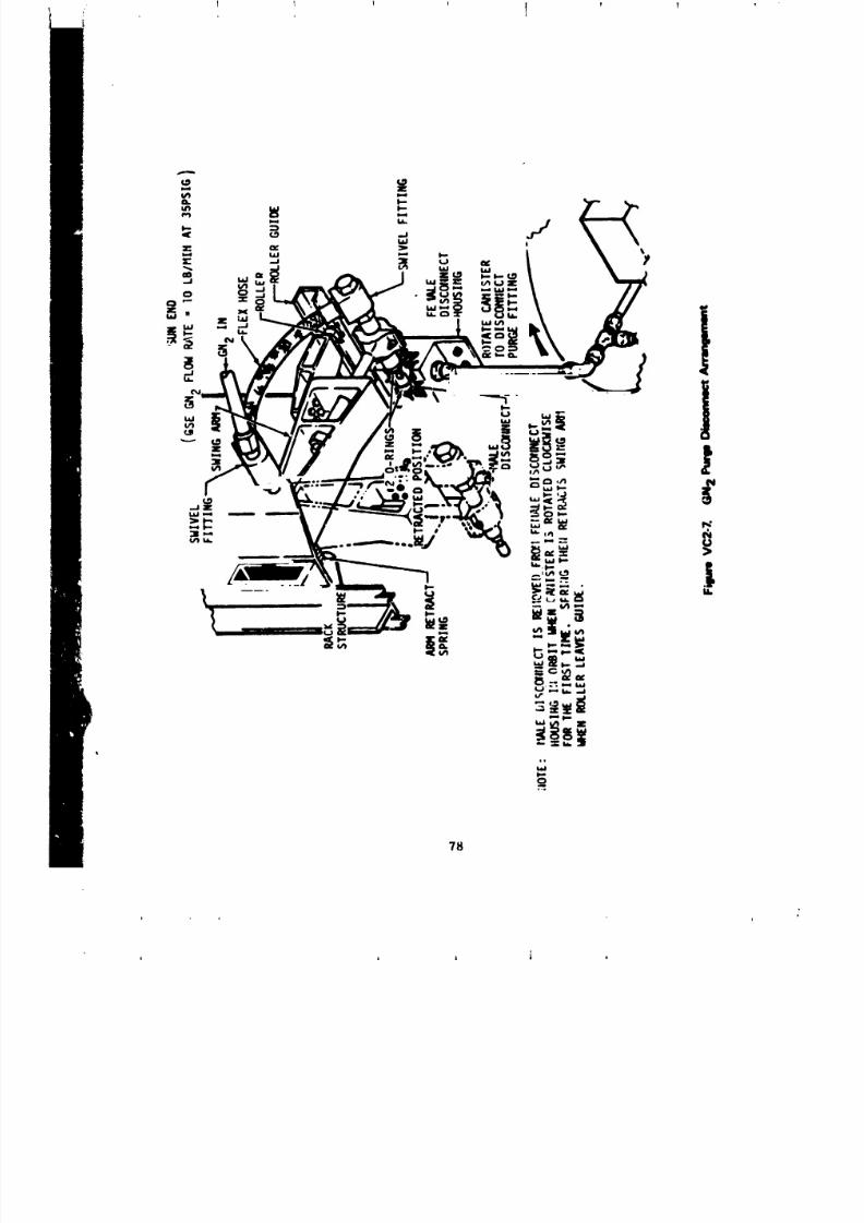
8/8/2019 MSFC Skylab Structures and Mechanical Systems Mission Evaluation
http://slidepdf.com/reader/full/msfc-skylab-structures-and-mechanical-systems-mission-evaluation 95/348
8/8/2019 MSFC Skylab Structures and Mechanical Systems Mission Evaluation
http://slidepdf.com/reader/full/msfc-skylab-structures-and-mechanical-systems-mission-evaluation 96/348
!
t
, "['he telescope mount solar array pavels are s_acked in a vertical
orientation at launch configuration. Tl .se panel stacks are supported
by cinching to a mounting structure. The telescope mount solar pcnel
cinching devices are released by means of pyrotechnic actuators. Ordnance
in the declnching mechanism (Figure VC2-8) consists of 2 EBW det-
onators, 2 CDF manifolds_ 16 CDF assemblies, and 16 CDF pressure
cartridges.
The pyrotechnics portion of the declnching mechanism consists of two
redundant ordnance systems with primary initiation by a signal £:om the
automatic instrumentation unit system and a secondary initiation provision
by a signal from the airlock digital command system. These signals
are used to trigger the £BW firing units. The firing unit initiates
the EBW detonator that is installed in a CDF manifold. The explosive
force is propagated through the CDF manifold and CDF assemblies to
CDF pressure cartridges. The output charge of the CDF assemblies to
CDF pressure cartridge actuates the solar power thruster assembly(Figure VC2-9).
The EBW firing unit charge command initgatlng solar array deployment
was sequenced for 17:54:48.7 and the trigger coalnand at 17:54:52.3.
Data confirming this sequence are not available for evaluation, however,
based on actual function cf the telescope mount solar array, there
c:an be no question as to the proper fua=tion of this system. Fly around
photographs show the fully deployed _olar array.
3. Aperture and Film Retrieval Doors.
a. Film retrieval doors. The manually operated film retrieval
_,oors are _hown in Figure VCI-I and VC3-1. These doors provide accessfor film cassette exchange.
During the entire Skylab mission, the SO82A film retrieval
door was opened _nd closed seven times and the $O8_B door five times.
Operation of S082 door was without incident. The $O82B door exhibited
stickiness or, two occasions, however, the film _xchanges were accomplished
successfully.
"[h,_ film retrieval doors accessible from the center work station
are sttown iu Figure VC3-I. These doors are m_ruaily operated and the
t:anister mu_r be rolled to gain access to each of the doors.
The doors were qualified for 320 cycles of closure and relock with an
operating force of I0 lb or less.
The center wor' station film retrieval doors operated as d_Igned
with no anomaly. On day 26 of the first manned phase, the crew indicated
that the S054 film retrieval door would not lock mechanically but was
b'_ing held clo_;ed by the magnetic secondary latching system. However,
79
t J i A _ l

8/8/2019 MSFC Skylab Structures and Mechanical Systems Mission Evaluation
http://slidepdf.com/reader/full/msfc-skylab-structures-and-mechanical-systems-mission-evaluation 97/348

8/8/2019 MSFC Skylab Structures and Mechanical Systems Mission Evaluation
http://slidepdf.com/reader/full/msfc-skylab-structures-and-mechanical-systems-mission-evaluation 98/348
1 I 1 '1
J _ I J i
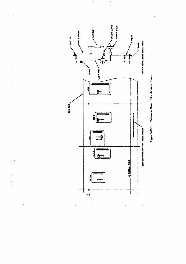
8/8/2019 MSFC Skylab Structures and Mechanical Systems Mission Evaluation
http://slidepdf.com/reader/full/msfc-skylab-structures-and-mechanical-systems-mission-evaluation 99/348
X lg
• 8_. | -.
.[1" '
E
z j
j"4...
I°_,°, ,
1
P-- Z
w
il °i
--. _ J
82 I
I
8/8/2019 MSFC Skylab Structures and Mechanical Systems Mission Evaluation
http://slidepdf.com/reader/full/msfc-skylab-structures-and-mechanical-systems-mission-evaluation 100/348
the second crew reported the S054 door was mechanically locked and operated
normally. During the Skylab mission, the doors were used a total of si=
times each.
b. Aperature doors. Eight telescopes and the five sun sensors
are installed inside the telescope mount experiment canister. The optics are
aligned for observation through apertures in the canister sun shield
bulkhead. These apertures are covered by movable doors that aid thermal
and contamination control for the complete experiment canister. Doors
are operated by electromechanical eystems mounted on the inside of the
sun shield bulkhead. Door arrangement and identification are shown
in Figure VC3-2.
Deslgn criteria for the i0 aperture doors are service life of
5,000 cycles, capability for automatic operation, and capability to
manually open and disable in the event of motor mechanism failure.
An aperture door drive mechanism is shown in Figure VC3-3. Each
aperture door consists of a fiber glass shell filled with aluminized mylar
with a shaft attached to one corner and a tapered latch opposite the
shaft. The tapered door latch fits into a "U" shaped ramp latch stop
attached to the sun shield to retain the door during ascent.
A bulb-shaped seal of silicone rubber, covered with a low frictional
cloth called "NOI_X," was attached to the perimeter of the door face
to seal the aperture at the sun shield ramp. A release pin and clutch
permits manual disabling and disabling latches restrain the door in the
open position.
The door drive mechanism consists of two redundant 28 Vdc torque
motors, a spindle with an Acme thread, a carriage, a motor lever, amotnting bracket, and limit switches (Figure VC3-3). The torque
mu_or rotates the spindle to move the carriage and the lever. The lever
rotates the door shaft to swing the door open and closed. Open and
closed positions are controlled by limit switches backed up by spindle
hard stops.
]nJtial operation of the aperture doors began during the first
manned phase (mission day 3) after the telescope mount was activated.
Operations occurred without incident until mission day 9 when the S054
door malfunctioned. A door by door review of flight performance follows:
(I) $054 aperture door. A review of the astronaut
communications during the first manned phase showed that malfunction
procedures were accomplished and that the door was stuck in the closed
position. The crew then opened the door with both motors and a decision
was made to temporarily leave the door open.
83
i
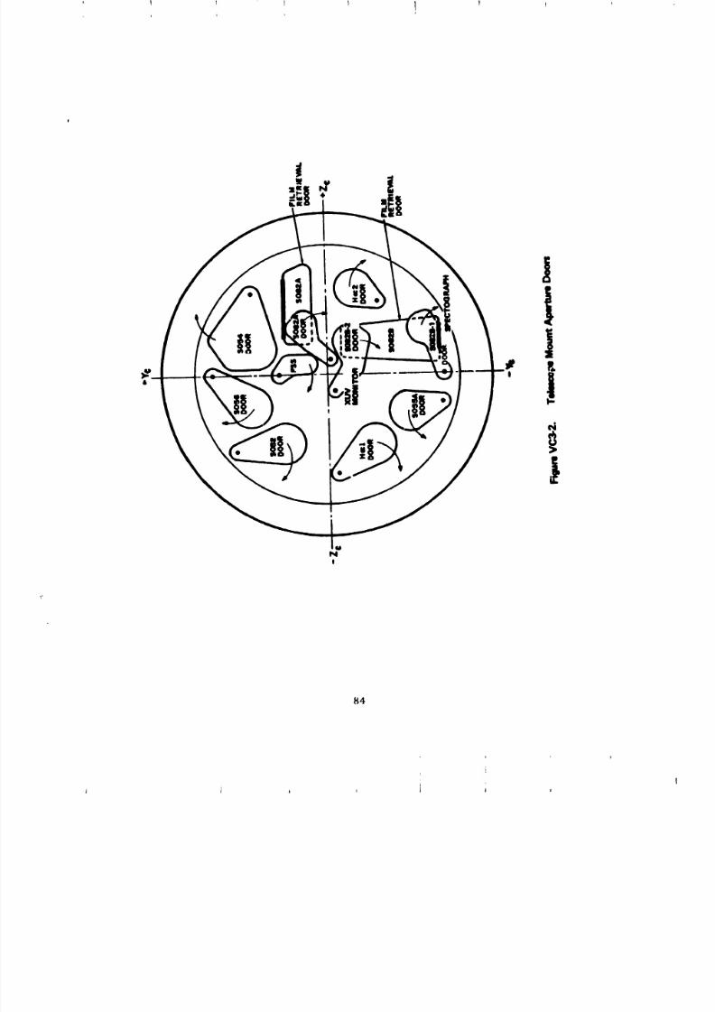
8/8/2019 MSFC Skylab Structures and Mechanical Systems Mission Evaluation
http://slidepdf.com/reader/full/msfc-skylab-structures-and-mechanical-systems-mission-evaluation 101/348
1 1 1 I t 1 !
84
J
I J J J
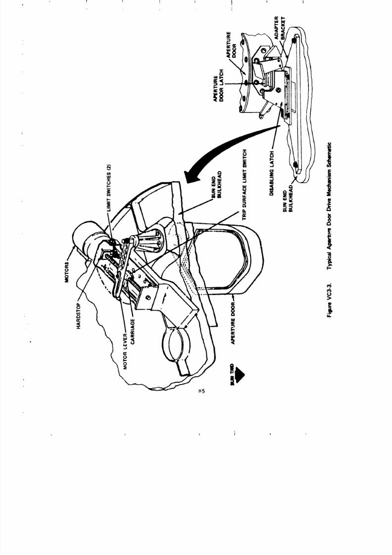
8/8/2019 MSFC Skylab Structures and Mechanical Systems Mission Evaluation
http://slidepdf.com/reader/full/msfc-skylab-structures-and-mechanical-systems-mission-evaluation 102/348
8/8/2019 MSFC Skylab Structures and Mechanical Systems Mission Evaluation
http://slidepdf.com/reader/full/msfc-skylab-structures-and-mechanical-systems-mission-evaluation 103/348
8/8/2019 MSFC Skylab Structures and Mechanical Systems Mission Evaluation
http://slidepdf.com/reader/full/msfc-skylab-structures-and-mechanical-systems-mission-evaluation 104/348
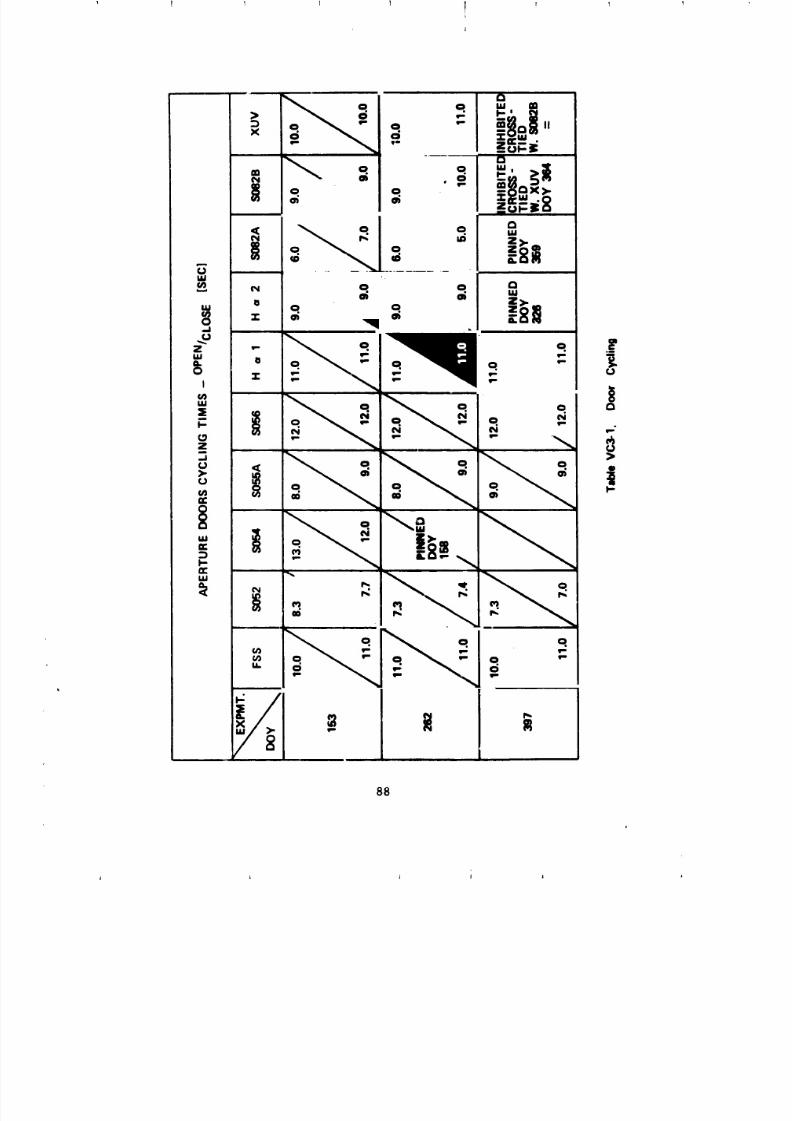
8/8/2019 MSFC Skylab Structures and Mechanical Systems Mission Evaluation
http://slidepdf.com/reader/full/msfc-skylab-structures-and-mechanical-systems-mission-evaluation 105/348
I
88
8/8/2019 MSFC Skylab Structures and Mechanical Systems Mission Evaluation
http://slidepdf.com/reader/full/msfc-skylab-structures-and-mechanical-systems-mission-evaluation 106/348
8/8/2019 MSFC Skylab Structures and Mechanical Systems Mission Evaluation
http://slidepdf.com/reader/full/msfc-skylab-structures-and-mechanical-systems-mission-evaluation 107/348
1 ? _ 1 f ;
i
1. Hard anodize and coat aluminum working surfaces
with a lubricant which does not require baking to eliminate annealing
of the coated aluminum.
2. Do not design devices that have a launch/ascent
environment protection function which must also be used operationally,
but serve no operational function.
3. When reviewing generalized timing data for trends i
be alert to the possibility that the problem phase may be so minute that
it is not recongnizable within the times recorded.
4. Thermal Control System Hardware. The telescope mount thermal
control system consists of an active and passive system that provides
a controlled temperature environment for the performance of the
experiments and supporting equipment. The active system provides thermalcontrol for the canister experiment package by means of a cold plate/
radlator/heater network. The entire canister is insulated with a
multilayer aluminized Mylar shroud that isolates the experiments and
canister from the external environment and rack-mounted equipment.
The spar is thermally insulated to provide minimum spar temperature
transients and gradients, and to maintain the required alignment between
the telescope mount telescopes and the fine sun sensor. The rack-
mounted support equipment is thermally controlled by passive means.
This is achieved with insulation, low conductance mounts, and thermal
coatings. Also, several telescope mount experiments and rack-
mounted equipment contain individuall thermostatically controlled heaters
to provide for internal temperature control.
The active thermal control system (Figures VC4-1 and VC4-2)
is a fluid (80 percent methanol/20 percent water) coolant loop that
rejects heat from the solar experiments. The heat from the experiments(500 W max.) is radiated to the walls (panels) of the telescope
mount canister. The coolant flow to the upper and lower canister half
Js equal.
The division of the flow is obtained by adJustl.ent of two flow
path restrictor valves. The valves were adjusted and locked in position
during checkout of the telescope mount thermal control system. The heat
collected by the canister panels is transferred to the coolant,
and the cool_nt is pumped to radiators for heat rejection to space.
The temperature control system consists of a modulating flow control
valve (mixing valve, electronic controller, heater, temperature sensor,_nd radiator bypass). The modulating flow control valve (MFCV) mixes
coolant from the radiator and bypass to provide canister inlet temperature.
The heater is located in the bypass line and is activated when the tem-
p_ratur_ falls below 47.7 °F.
9O
L J l t J
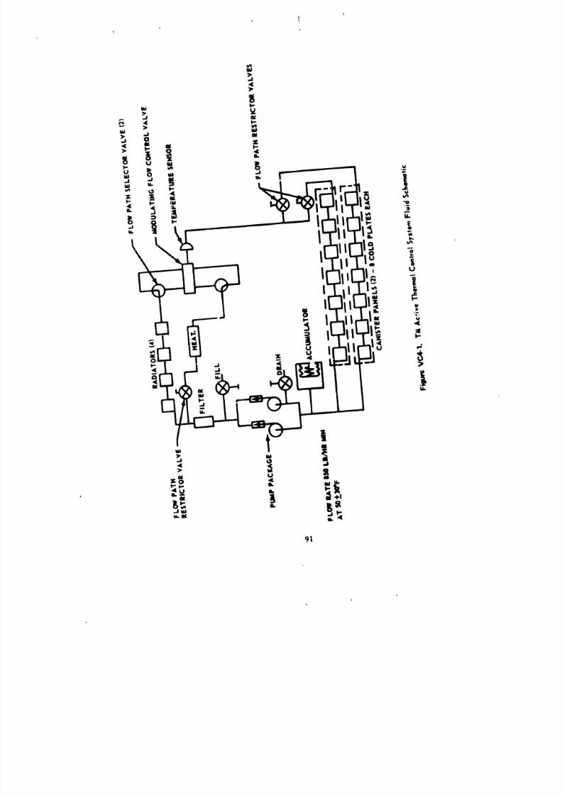
8/8/2019 MSFC Skylab Structures and Mechanical Systems Mission Evaluation
http://slidepdf.com/reader/full/msfc-skylab-structures-and-mechanical-systems-mission-evaluation 108/348
, 1
91
ii
J
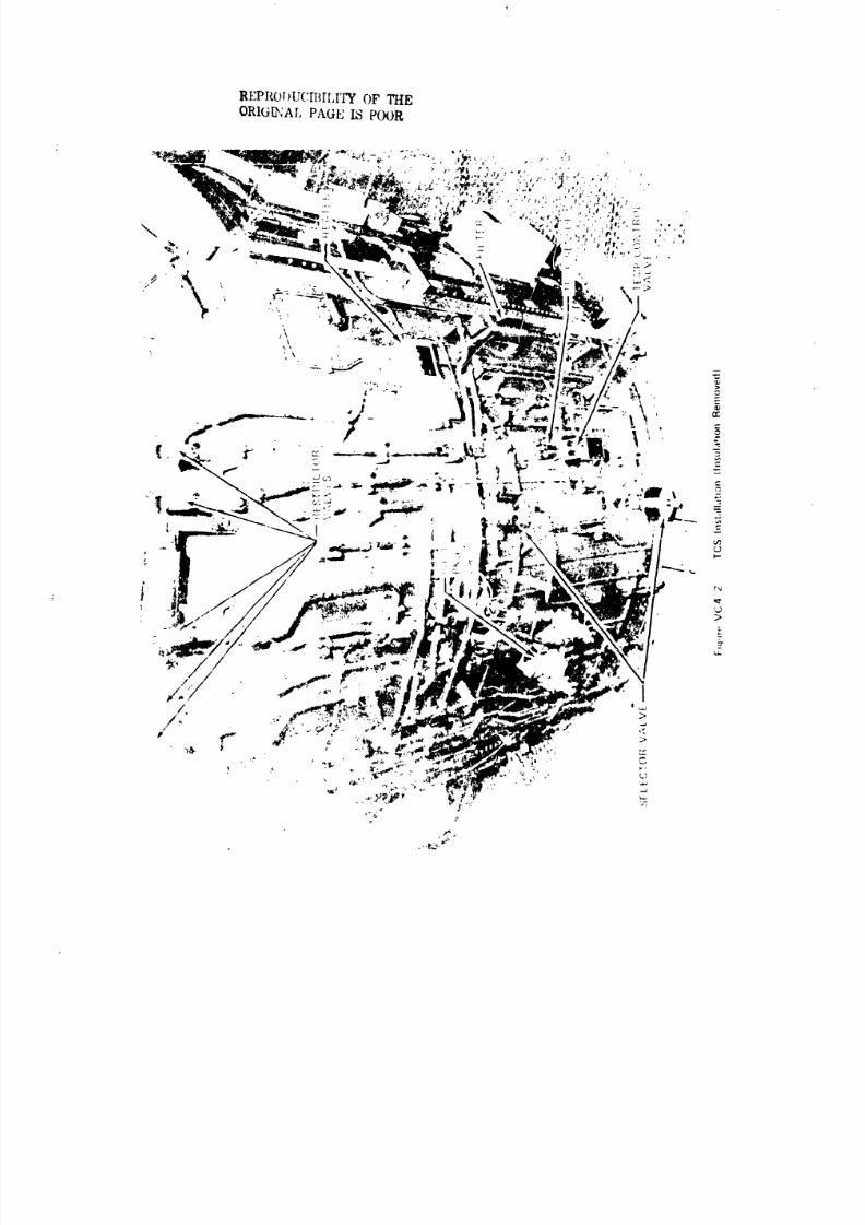
8/8/2019 MSFC Skylab Structures and Mechanical Systems Mission Evaluation
http://slidepdf.com/reader/full/msfc-skylab-structures-and-mechanical-systems-mission-evaluation 109/348
REPROIIUCITIIIZI'Y OF THE
ORIGI_AD PAGE IS POOR
8/8/2019 MSFC Skylab Structures and Mechanical Systems Mission Evaluation
http://slidepdf.com/reader/full/msfc-skylab-structures-and-mechanical-systems-mission-evaluation 110/348
The thermal control system coolant accumulator provides a positive
pressure at the pump inlet_ allows for thermal expansio_jcontraction,
and provides makeup fluid for leakage. Fill and drain valves are the
same configuration as the flow path restrlct r valves. A second
flow path restrlctor valve is installed in the bypass llne upstream
of the heater to allow for equalization of flow resistance in the
radiator and radiator bypass portion of the system.
Two flow pat_, selector valves are upstream of the MFCV to select
either the prima/y or secovdary MFCV.
During system devalopment, two significant problems were encountered:
coolant pump bearing swell and seizure, and temperature control instability.
a. the coolant pump hearing material (Fiberlte; TFE-- a
fluorocarbon resin) was selected to eliminate corrosion between the bearing
and the coolant medium. Long term exposure to the coolant resulted in
bearing swell and finally seizure. The design fix utilized the aame } _ring
material. However, the b_aring assembly was modlfleo to allow for aetermined
&well rates and long llfe capability.
b. The temperature control instability was the result or:
I. High response rate of the modulating flow control
valve.
2. Modulating flow control valve flow c:lentatlon
with respect to the valve flapper.
3. Electronic controller response rate.
4. Inadequate fluid mixing at the temperature sensor.
The effect of the above described conditions was valve
[nstabillty and inadequate temperature control.
The system was modified by reiocatln$ components such that
fluid pressure oppL, sed the valve flapper movement, making the system more
dynamically stable. The controller gain was decreased and fluid mixing
was improved to prevent temperature stratlflca_ion at the temperature
_ensor.
The pump (F_gure VC4-3) was qualified for a flow rate of
850 Ib/hr minimum of BO percent methanol/20 percent water at 31 peid
and life of 6,672 hr.
During the Skylab mission, the flow rate varlea, as a
[t_r_,:t|,,l_,[ MICV l,,,sit[on, between 925 and 975 Ib/hr. The pressure rise
of th*. [,,u,pvaried between 26.5 and 2/.75 psi.
93
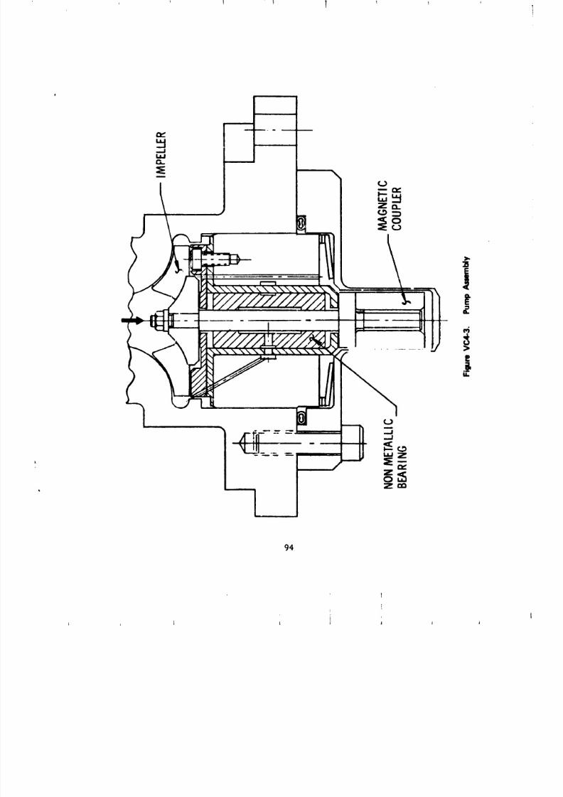
8/8/2019 MSFC Skylab Structures and Mechanical Systems Mission Evaluation
http://slidepdf.com/reader/full/msfc-skylab-structures-and-mechanical-systems-mission-evaluation 111/348
1 1 1 1
94
L l j i
8/8/2019 MSFC Skylab Structures and Mechanical Systems Mission Evaluation
http://slidepdf.com/reader/full/msfc-skylab-structures-and-mechanical-systems-mission-evaluation 112/348
.A. .. ... .. .. .. .. .. .. .. .. . mrrr._ _'"_R'_' .... . _ .............. _,_....°__,.._._ .......... .n,,,,, _ . .. ... .. .. .. .. .. ... .. . L . .. .. .. .. .. ... .. .. . -._-_-_,-_-._- i
The primary pump operated for 6,154 hr of flight time and
305 hr prior to flight with no problems.
The secondary pump operated for 2 hr in flight and for
216 hr prior to flight, after being dormant for approximately 275 days.
The flow rate was comparable to the flow rate experienced during preflight
_heckout of 875 ib/i_r.
The accumulator was qualified to maintain pump inlet pressure
above 7 psia, to prnvide flumd for leakge, and to provide for thermal
expansion and contraction between bulk coolant temperatures of -65 to
lO0 °F.
During the Skylab mission_ the pump inlet pressure was
always above 12 psia with no detectable leakage.
The main flow control valve was qualified to fully open to
radiator flow at an outlet valve temperature of 51 °F, to fully open to
heater flow at an outlet valve temperature of 49 °Fj and to maintain a
valve outlet temperature of 50 +__i°F. During thermal vacuum testing,
the valve set point appeared to be 49.7 °F.
During the Skylab mission, two excursions were noted during
the early part of the first manned phase, and the temperature control point
appeared to have shifted downward by about 0.36 °F from the control
point noted during the ground thermal vacuum testing. Also, the temperature
control point did not appear as stable as that noted during the thermal
vacuum testing. One explanation for the temperature excursion is that
contamination in the coolant prevented the valve from fully closing
as the radiator [luid ten_perature decreased. As the temperature of
the radiat_r warmed up, allowing the valve to open, the contamination
washed through the valve and was trapped in the filter. After several
days, the system was cleaned by the filter. The reason for the long
rleaning time is that the radiator flow was very small. The small flow
prevented a good thorough flush of the radiator.
l.'orfuture design it is recommended that filters be installed
at t;,e inh, t of valves with close operational tolerances. Breadboard
the syutem as early as possible to detect instabilities. Locate
valves and sensors at mixing points to reduce system lags.
5. Extravehicular Activity llardware. A crew translatio, hardware
,_y:.tem is i_stalled on the telescope mount external structure to
provide support for extravehicular activity. The system consists
of i_andrails, foot restraints, and life support umbillcal clamps. Three
extravehicular act[vlty work stations are provided at the rack structure:
the center work statiun located at the open rack bay 45 ° between the
telescope mount coordinate axes +Z and Y; the transfer work station
located ,tr the edge of the solar shield; and the sun end work station
[ocated on the outer surface cf the solar shield. Figure VC5-1
depicts the arrangement of this hardware.
95
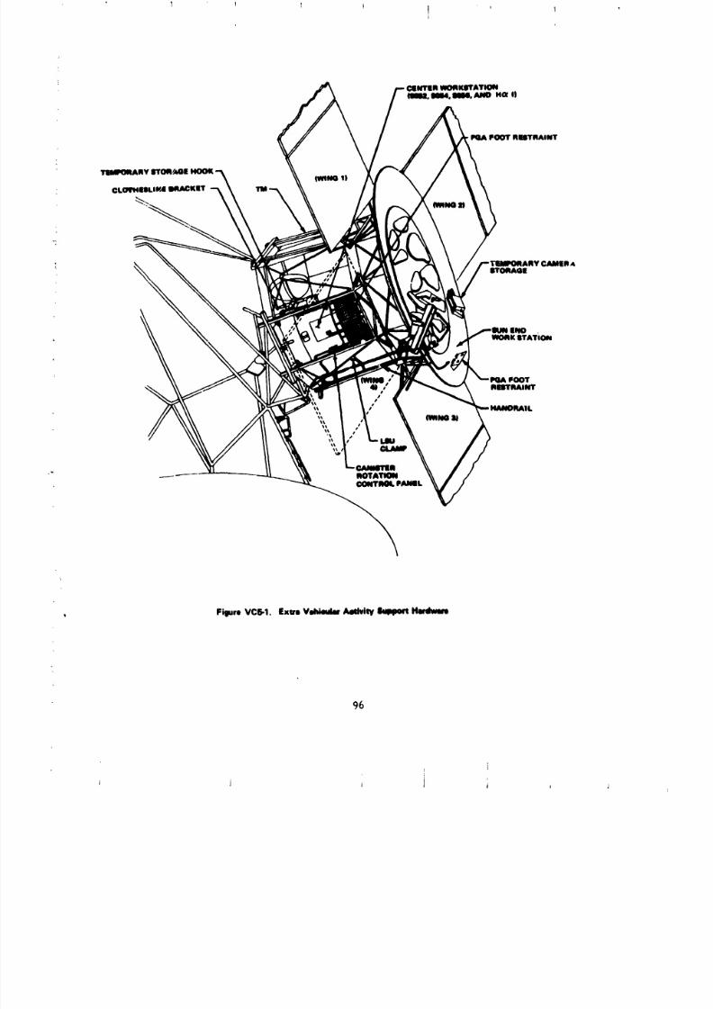
8/8/2019 MSFC Skylab Structures and Mechanical Systems Mission Evaluation
http://slidepdf.com/reader/full/msfc-skylab-structures-and-mechanical-systems-mission-evaluation 113/348
INOWORK_rATION
FOOTIIIITIIAINT
FigureVC5-1. Exn VehiedarAedvlW Ikqqmr_Hmlwem
%
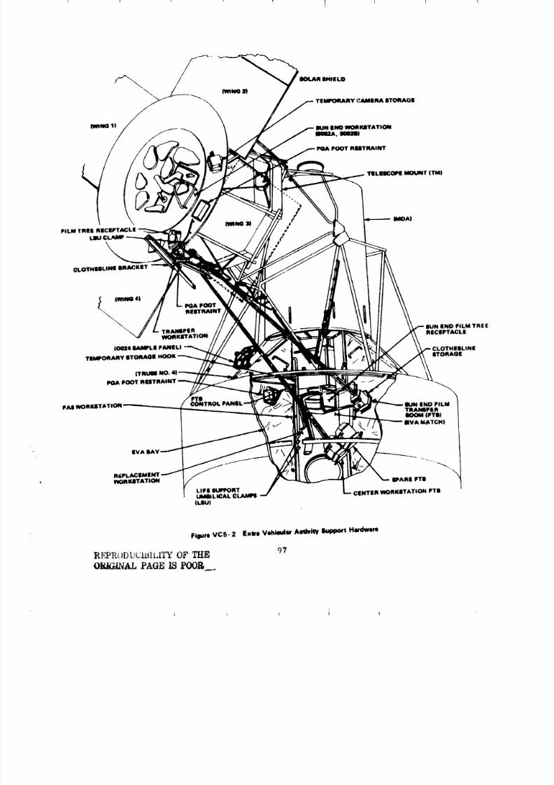
8/8/2019 MSFC Skylab Structures and Mechanical Systems Mission Evaluation
http://slidepdf.com/reader/full/msfc-skylab-structures-and-mechanical-systems-mission-evaluation 114/348
CLOTHlil IUNE BRACKET
_ IWlNO 41 PORT
POARESTRAINT
\TRANIFER END FiLM TREEWORKITATION RECEPTACLE
10024 I_MMPLE PANEL)
d $TORAGE
|TRUII NO.
PGA FOOT RESTRAINT
FAll WORKITA1END FILM
TRANIIFERBOOM |FTR)
(EVA MATCH)
Figure VC5- 2 Exwl Vehicular AeltviW Support Hardware
REPR()DUCIi31LITYF THE 97
ORiGiNAL PAGE ISPO0_.__
8/8/2019 MSFC Skylab Structures and Mechanical Systems Mission Evaluation
http://slidepdf.com/reader/full/msfc-skylab-structures-and-mechanical-systems-mission-evaluation 115/348
-_'_'_.... "__" ......... _ ..............................................................................-_---....................?.................................I...................-_1
Transfer of experiment film cassettes and cameras is accomplished
by: camera trees and tree receptacles, film transfer booms_ and aclot,_esline system.
a. Telescope mount handrails. The basic requirement
for the extravehicluar activity film retrieval handrails was to provide
a route for the crewman from the airlock hatch to the center work
station and to the sun end work station on the telescope mount.
The telescope mount handrails consist of a single rail adjacent
to the outrigger s dual rails from the outrigger to the sun end between
the solar array panels, and a single handrail from the outrigger to
the center work station. Figure VC5-1 shows the location of the telescope
mount handrails in the extravehicular activity path.
A design criterion for the hand rails was that they be
designed for an ultimate load of 600 ib at any location. With
this load and the long span between supports, steel was required for
the handrails.
Additional constraints on the rails s supports, and fasteners
were that they have no sharp edges or burrs. Protruding bolts and nuts
are _voided where possible, and where necessary the nuts are covered with
RTV-140 to ensure no burrs. Also, the handrail routing is configured
to provide clearance to the payloaG s_,roud in the launch configuration.
The handrails were i_stalled on the telescope mount
vibroacou_tic test article and no problems were found. The strength of
the rails was verified by anaiysls and utilized in neutral buoyancy testing.
The functional adequacy of the handrails was verified by
neutral buoyancy training of the crewmen
The shape of the cross section of the handrails is satisfactory
and the overall design was adequate based on crew comment. It is
recommended for future applications that a 200-1b design limit load be used
for handrails co_ensurate with alrlock handrail design criteria, which was
found to be satisfactory.
b. Extravehicular activity foot restraints. To accommodate
hand tasks, extravehicular actlvity-type foot restraints are provided at
various Saturn workshop exterior locations and a portable restraint wasprovided in the workshop.
The te!=scope mount foot restraints are designed for a lO0-1b
co_centrated load at the heel clips and an 1800 in.-Ib torsional
ioad. The plate and heel anJ toe clips are made from 7075-T73 aluminum.
The structural integrity of the foot restraints and their
installation was verified by analysis.
98
8/8/2019 MSFC Skylab Structures and Mechanical Systems Mission Evaluation
http://slidepdf.com/reader/full/msfc-skylab-structures-and-mechanical-systems-mission-evaluation 116/348
, The foot restraints were installed on the vibroacoutic
test article and no problems were found.
A set of "boot gages" was provided by JSC that represents
maximum and minimum tolerance of boot he_l clips. These were tested in
a qualification test foot restraint at ambient, low, and high temperatures,
and no problems were found.
The functional adequacy of the foot restraints was verified by
neutral buoyancy training 3f the crewmen.
Foot restraints satisfactorily performed their function
during use by the Skylab flight crews.
c. Umbilical clamps. To aid in managing the umbilicalduring extraJehicular activities, a requirement to provide a clamp for
the umbilical adjacent to the center work station and between the transfer
work station and the sun end work station was established. Also, two of
these clamps are located in the fixed alrlock shroud area for management
of both umbilicals used by extravehicular activity.
The clamps were designed with a fixed jaw and an over center,
spring loaded, movable jaw that could be opened for inserting the umbilical.
The movable jaw clamped over the fixed jaw after inserting the umbilical.
The jaws are lined with a 0.13-in. layer of moslte rubber to provide
a friction surface and to protect the umbilical. The linkage for the
over center spring-loaded movable Jaw is critical to ensure that the Jaw
will remain o[en when set in the over center position, but still close
positively when the umbilical is inserted.
The structural integrity of the umbilical clamps was verified
by analysis.
A qualification test unit (flight design) was functionally
cycJed 150 tLmes, about 5 times the expected flight use, using a section
of simulated flight umbilical. Also, the qualification test
unit was subjected to the high and low temperature extremes expected
and cycled 12 times with no problems.
During neutral buoyancy training, it was determined that
sun end film retrieval could be accomplished without using the clamp.
[his clamp, however, was left on the telescope mount for potentialunanticipatud requirements. It is questionable whether the clamp at the
telescope mount center work station was a necessity and some crewmen
did not use it as stated in crew debriefings.
Clamps used by crewmen performed satisfactorily in retaining
inserted umbilicals.
99
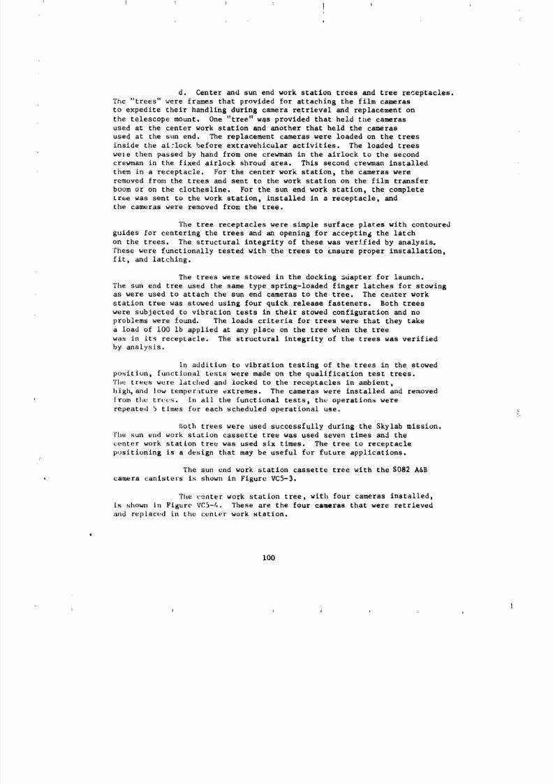
8/8/2019 MSFC Skylab Structures and Mechanical Systems Mission Evaluation
http://slidepdf.com/reader/full/msfc-skylab-structures-and-mechanical-systems-mission-evaluation 117/348
d. Center and sun end work station trees and tree receptacles.
The "trees" were frames that provided for attaching the film cameras
to expedite their handling during camera retrieval and replacement on
the telescope mount. One "tree" w_s provided that held the cameras
used at the center work station and another that held the cameras
used at the sun end. The replacement cameras were loaded on the trees
inside the ai:lock before extravehicular activities. The loaded trees
wele then passed by hand from one crewman in the airlock to the second
crewman in the fixed airlock shroud area. This second crewman installed
them in a receptacle. For the center work station, the cameras were
removed from the trees and sent to the work station on the film transfer
boom or on the clothesline. For the sun end work station, the complete
tree was sent to the work station, installed in a receptacle, and
the cameras were removed from the tree.
The tree receptacles were simple surface plates with contoured
guides for centering the trees and an opening for accepting the latch
on the trees. The structural integrity of these was verified by analysis.
These were functionally tested with the trees to ensure proper installation,
fit, and latching.
The trees were stowed in the docking sdapter for launch.
Tile sun end tree used the same type sprlng-loaded finger latches for stowing
as were used to attach the sun end cameras to the tree. The ce_ter work
station tree was stowed using four quick release fasteners. Both trees
were subjected to vibration tests in their stowed configuration and no
problems were found. The loads criteria for trees were that they take
a load of i00 ib applied at any place on the tree when the tree
was in its receptacle. The structural integrity of the trees was verified
by analysis.
In addition to vibration testing of the trees in the stowed
position, functional tests were made on the qualification test trees.
The trees were latched and locked to the receptacles in ambient,
high, and low temperature extremes. The cameras were installed and removed
from the try:us. In all the functional tests, the operations were
repeated 5 times for each scheduled operational use.
Both trees were used successfully during the Skylab mission.
The sun end work station cassette tree was used seven times and the
center work station tree was used six times. The tree to receptacle
positioning is a design that may be useful for future applications.
The sun end work station cassette tree with the S0B2 A&B
camera canisters is shown in Figure VC5-3.
The ¢:enter work station tree, with four cameras installed,
is shown in Figure VC5-4. These are the four cameras that were retrieved
aud replaced Ln the center work station.
I00
i i I i i I i
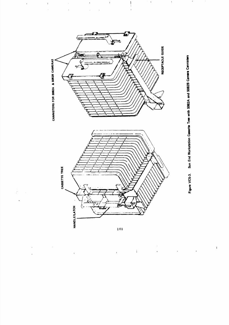
8/8/2019 MSFC Skylab Structures and Mechanical Systems Mission Evaluation
http://slidepdf.com/reader/full/msfc-skylab-structures-and-mechanical-systems-mission-evaluation 118/348
I I I ] i !i
q I
'
i t J Jl l
t
8/8/2019 MSFC Skylab Structures and Mechanical Systems Mission Evaluation
http://slidepdf.com/reader/full/msfc-skylab-structures-and-mechanical-systems-mission-evaluation 119/348
1 t _ I 1 1I
102-
I I i J i I I
8/8/2019 MSFC Skylab Structures and Mechanical Systems Mission Evaluation
http://slidepdf.com/reader/full/msfc-skylab-structures-and-mechanical-systems-mission-evaluation 120/348
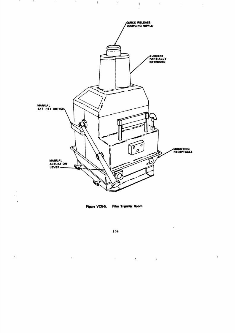
8/8/2019 MSFC Skylab Structures and Mechanical Systems Mission Evaluation
http://slidepdf.com/reader/full/msfc-skylab-structures-and-mechanical-systems-mission-evaluation 121/348
RELEASEING NIPPLE
EXTENOED
MANUALEXT-RET
RECEPTACLE
MANUALACTUATIONLEVEl
Figure VC5-5. Film Tmmbr Boom
104
I i j i
8/8/2019 MSFC Skylab Structures and Mechanical Systems Mission Evaluation
http://slidepdf.com/reader/full/msfc-skylab-structures-and-mechanical-systems-mission-evaluation 122/348
On the telescope mount, a clothesline "pole" is installed
adjacent to the center work station m.d one adjacent to the transfer
work station at the sun end. The optimum location for the pole tip,
where the clothesline hooks attach at the work stations, was determined
in early neutral buoyancy simulation. To keep the clotheslines and
camera transfers out of the work area, the pole tips _ere required to
be at a considerable distance from the work station. This necessitated
installing the poles in a stowed configuration that was inside the payload
shroud envelope and then deploying the poles to their required operational
configuration. The center work station pole is hinged and deployed
at variable angles with a spring loaded detent. The sun end pole was
secured in the launch configuration with a quick release pin and latched
in the deployed position with a spring-loaded detent and a spring latch.
The poles were designed for a maximum load of 300 Ib eppliedat the tip after deployment. This load is not realized during clothesline
operation, but a crewman could conceivably apply equivalent dynamic lead
during deployment or in emergency hand hold use.
The center work station pole was vibration tested on the
vibroacoustic test article and subsequently functionally tested by
deploying it 5 times the maximum anticipated flight use at ambient,
high, and low temperature extremes.
The sun end closthesline pole assembly was vibration tested
on a test fixture and functionally tested by deployln 8 it at ambient, high,
and low temperature extremes.
The clothesline cord material was PBI cord. The splices
were made using PBI thread with a coating of Silastic RTV-140 over the
splice to prevent fraying. A section of the cord containing a splice
joint was tested for strength after fabrication and then was subjected to
the equivalent of 2,000 hr of sun exposure in a vacuum and retested.
The average load at failure for three specimens on the initial test was
427 ib and at the cud of exposure the average load at failure for three
specimens was 352 lb. Based on these tests, th_ material was considered
satlsfactory.
The structural integrity of the hooks used with the clothes-
line was verified by analysis. Qualification test hooks were subjected to
cyclic testing at ambient, high, and low temperature extremes. The nu:,ber
of cycles was at least five times their maximum expected use with nofailures; therefore, the hooks were considered qualli_d.
From the crew debriefing, it is evident that the decision
to,use the film transfer boom as the primary system was the right one. The
cameras were successfully retrieved using the clothesline system, but the
crewman found chat the cords could easily be tangled and thus additional
time was required to straighten them.
105
8/8/2019 MSFC Skylab Structures and Mechanical Systems Mission Evaluation
http://slidepdf.com/reader/full/msfc-skylab-structures-and-mechanical-systems-mission-evaluation 123/348
ri i
m
.
?
To sun_narize, the functional aspect of the clothesline
system worked well. Its presence did not compromise the use of the prlme, rysystem, but it was not as efficient a system as the film transfer boca.
This is substantiated by the following comments made by the third Skylab
crew during debriefing on February 22, 1974:
CARR - "Boom operation - The booms Just worked llke champs.
We found them to be superior to the clothesline operation because you
didn't have the tangle, the intertwining problem, that you had with the
clothesline. I chink our modes of operation were the right way to go. The
boom is the prime mode and the clothesline is the backup mode if the boom
fails. The clothesline mode is a good mode of operation. It's quiteusable but it take more time and it's a little more trouble".
GIBSON - "Talking about clotheslines gets into what we
encountered
during
the la
st
EVA. That wa
sthe amou
nt of
clutte
rwe
hadin the FAg work station in the way of clotheslines. We had two clotheslines
out in the stem. We had all the ATM flim which was stowed back there
which we had retrieved. We had S020 out and T025, and a DAC out there and
or a Nikon, and two people up in that area working. I found it really did
get crowded. We were able to get it all sorted out. I believe that's
a higper level of mechanical and geometric complexity than you should put
into an EVA. Also, that's when I got the rope from the clothesline hooked
into my PCU".
f. Temporary stowage components. Film retrieval aids for
temporary stowage of the cameras at the work stations consisted of acontainer at the sun end work station where the S082 camera could be stowed
durln E replacement. This container was a simple aluminum box, which
allowe
d aSout 1-in.
clearan
ce
aroun
dthe
camer
aenvelop
e,and
plasticsnubbers to keep the camera contained. This design was verifiad by analysis.
At the fixed airlock shroud L,d center work stations, permanently mounted
temporary stowage hooks were provided for holding the film camaraa
t_mporarily during replacement operations. These were a similar
design to the clothesline hooks and the design was verified by _lalysis
and functional testing at ambient, high, and low temperature extremes.
Both the temporary stowage container and the temporary
stowage hooks were used during extravehicular activities. Their use
during this complex activity aided Skylab crewmen.
106
i L j i

8/8/2019 MSFC Skylab Structures and Mechanical Systems Mission Evaluation
http://slidepdf.com/reader/full/msfc-skylab-structures-and-mechanical-systems-mission-evaluation 124/348
I !
D. Telescope Mount Deployment Assembly
The telescope mount deployment assembly is required to rigidly
-;upport the telescope mount in orbit in a position rotated 90 ° from the
launch axis. It was flexibly attached to the telescope mount ,ring launch
and boost through floatin_ Joints at the telescope mount interface, such
that the lateral and axial loads generated by the telescope mount were reacted
solc_ly by the payload shroud. Provisions to rigidize the flo_ting Joint
immediately upon shroud Jettison and prior to deployment of the telescopemount were made.
I. Deployment Assembly Structure. The deployment assembly structureconsists of two aluminum tubular trvss assemblies joined together by two
trunnion Joints (Figure VD-I) that allowed the upper truss assembly
to rotate through 90" to deploy the telescope mount. The lower truss
assembly is attached to the fixed airlock shroud at I0 places through rodends that allowed adjustment for precise telecope _, _nt alignment
The upper truss assembly incorporates four rigidizlng mechanisms attaching
to the telescope mount (Figure VD-2). The rlgidlzlng mechanisms
were capable of 2.0 in. deflection in all directions while the telescope
n_>unt was supported by the payload shroud, r_llo_ing payload shroud separation,
_prings in each rigldizing mechanism retracted and rigidly affixed the telescope
mount to the deployment assembly. An overcenter spring/lever mechanism
locked tim rigidlzing mechanisms in the retracted position. The deployment
assembly structure Is required to have a design safety factor of 3.0
time_; the maximum predicted loads to preclude extensive ground testing. The
stlf_ness of the deployment assembly structure in the deployed and latched
position is requtred to provide a minimum natural frequency of 0.6 Hz.
Ground verification of the static load capability was conJucted by
analyses to verify the design safety factors. A complete quali¢ication program
was conducted on the rigidi-ing mechanism to verify performance
at high (160 OF) and low (-70 °F) temperatures and after exposure to
humidity and the predicted flight vibration levels. A deployment
q_Lalification tes_ was run on a complete flight-typ,_ assembly with the
lon_itudinal axls in a horlzontal position. The unit was assembled and
aligned in one building then transported to another blilding with the
_round support and transport equipment. It was then set up vertically and
six deployment tests run to verify that alignment was not affected by
h;mdling and transporting. The unit was then set up in a horizontal
l,o_ition with the mas_/inertia chara_terlstics of the telescope mount
_imulated by the well, hi of the upper truss assembly and telescope mount
simulator, supported by a cable and pulley arrangement, and a full deploy-
munt test was satisfactorily completed. The first production f]ight-type
107
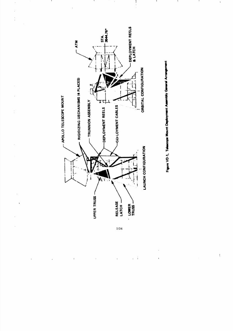
8/8/2019 MSFC Skylab Structures and Mechanical Systems Mission Evaluation
http://slidepdf.com/reader/full/msfc-skylab-structures-and-mechanical-systems-mission-evaluation 125/348
108
1 J I J i
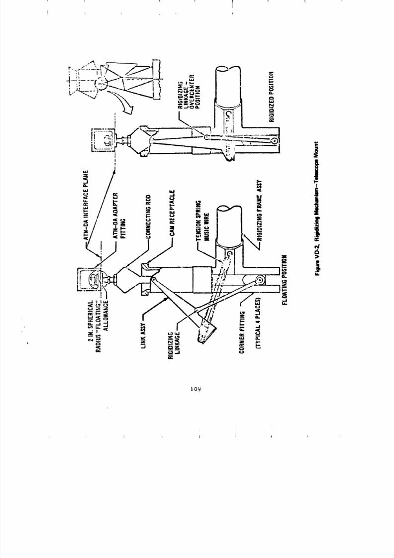
8/8/2019 MSFC Skylab Structures and Mechanical Systems Mission Evaluation
http://slidepdf.com/reader/full/msfc-skylab-structures-and-mechanical-systems-mission-evaluation 126/348
1 I ] ] 1 Ti
! ; I
109
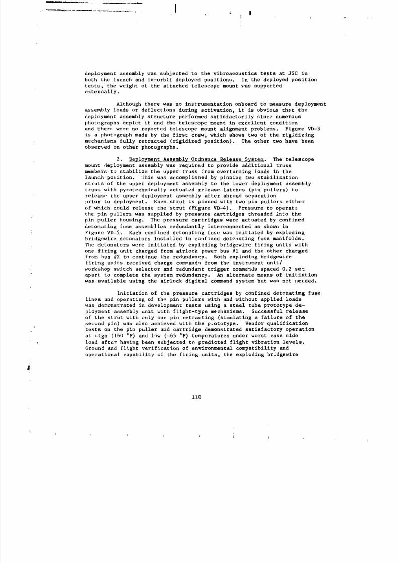
8/8/2019 MSFC Skylab Structures and Mechanical Systems Mission Evaluation
http://slidepdf.com/reader/full/msfc-skylab-structures-and-mechanical-systems-mission-evaluation 127/348
i
.... _ ................. _..................- .............. I Z l
deployment assembly was subjected to the vibroacoustics tests at JSC in
both the launch and in-orblt deployed positions. In the deployed position
tests, the weight of the attached telescope mount was supported
externally.
Although there was no instrumentation onboard to measure deployment
assembly loads or deflections during activation, it is obvious the,t the
deployment assembly structure performed satisfactorily since numerous
photographs depict it and the telescope mount in excellent condition
and there were no reported telescope mount alignment problems. Figure VD-3
is a photograph made by the first crew, which shows two of the rigidlzing
mechanisms fully retracted (rlgidized position). The other two have been
observed on other photographs.
2. Deployment Assembly Ordnance Release System. The telescope
mount deployment assembly was required to provide additional trussmembers to stabilize the upper truss from overturning loads in the
launch position. This was accomplished by pinning two stabilization
struts of the upper deployment assembly to the lower deployment assembly
truss with pyrotechnically actuated release latches (pin pullers) to
release the upper deployment assembly after shroud separation
prior to deployment. Each strut is pinned with two pin pullers either
of which could release the strut (Figure VD-4). Pressure to operate
the pin pullers was supplied by pressure cartridges threaded into the
pin puller housing. The pressure cartridges were actuated by confined
detonating fuse a_semblies redundantly interconnected as shown in
Figure VD-5. Each confined detonating fuse was initiated by exploding
bridgewire detonators installed in confined detenating fuse manifolds.
The detonators were initiated by exploding bridgewire firing units with
one firing unit charged from airlock power bus #1 and the other chargedfrom bus #2 to continue the redundancy. Both exploding bridgewire
firing units received charge commands from the instrument unit/
workshop switch selector and redundant trigger commands spaced 0.2 sec
apart to complete the system redundancy. An alternate means of initiation
wa3 available using the alrlock digital command system but wa_ not t_ceded.
Initiation of the pressure cartridges by confined detonating fuse
lines and operating of th_ pin pullers with and without applied loads
was demonstrated in development tests using a steel tube prototype de-
ployment assembly unlt with flight-type mechanisms. Successful release
of the strut with only one pin retracting (simulating a failure of the
second pin) was also achieved with the p_ototype. Vendor qualification
tests on the pin puller and cartridge demonstrated satisfactory operation
at high (160 °F) and low (-65 °F) temperatures under worst case side
, load after having been subjected to predicted flight vibration levels.
Groun2 and flight verification of environmental compatibility and
operational capability of the firing units, the exploding bridgewire
II0
I I l 1 j ,I j j
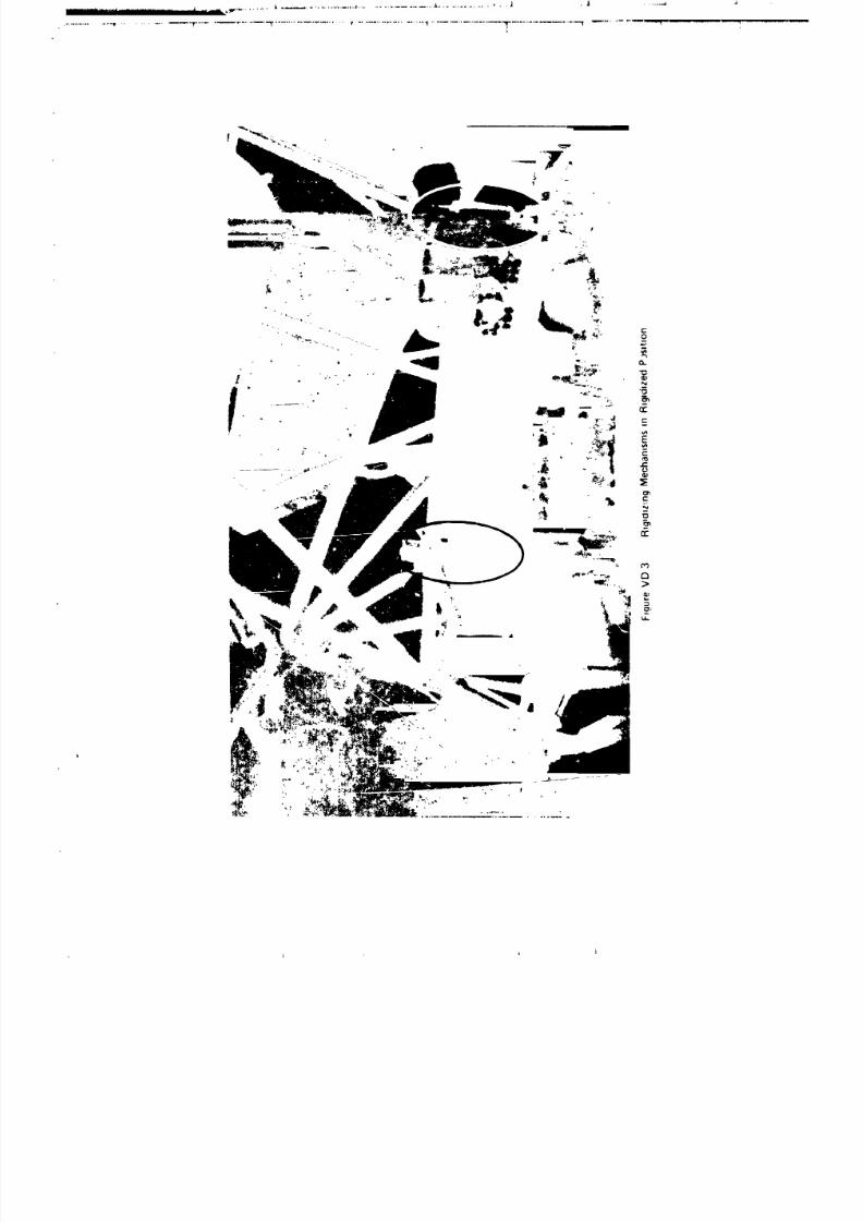
8/8/2019 MSFC Skylab Structures and Mechanical Systems Mission Evaluation
http://slidepdf.com/reader/full/msfc-skylab-structures-and-mechanical-systems-mission-evaluation 128/348
. _ . ' , I J I J
8/8/2019 MSFC Skylab Structures and Mechanical Systems Mission Evaluation
http://slidepdf.com/reader/full/msfc-skylab-structures-and-mechanical-systems-mission-evaluation 129/348
.......... I- '*_' _ '1 " _ .......... "_ ............... l ................................ f -- ! _v
11?
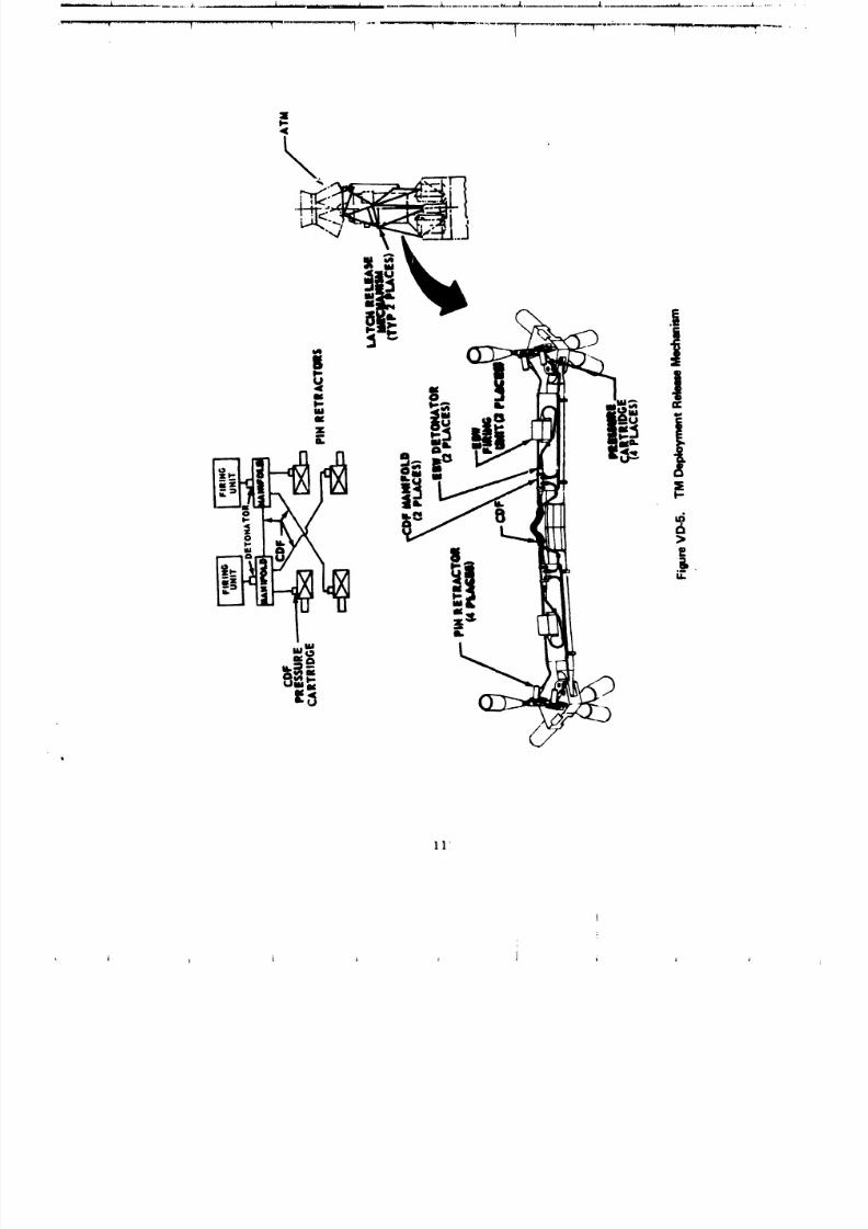
8/8/2019 MSFC Skylab Structures and Mechanical Systems Mission Evaluation
http://slidepdf.com/reader/full/msfc-skylab-structures-and-mechanical-systems-mission-evaluation 130/348
11
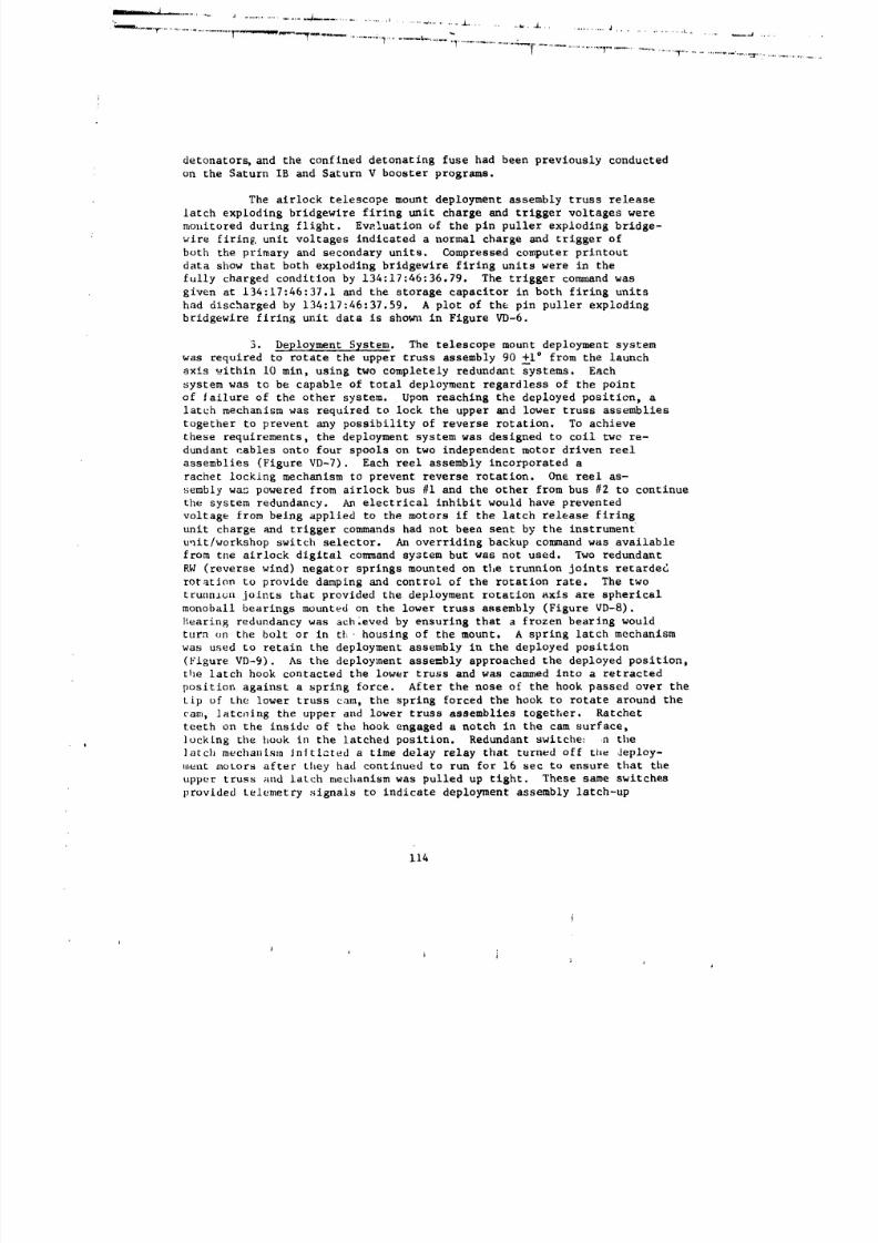
8/8/2019 MSFC Skylab Structures and Mechanical Systems Mission Evaluation
http://slidepdf.com/reader/full/msfc-skylab-structures-and-mechanical-systems-mission-evaluation 131/348
detonators, and the confined detonating fuse had been previously conducted
on the Saturn IB and Saturn V booster programs.
The airlock telescope mount deployment assembly truss release
latch exploding bridgewire firing unit charge and trigger voltages were
mox_itored during flight. Evaluation of the pin puller exploding bridge-
wire firing unit voltages indicated a normal charge and trigger of
both the primary and secondary units. Compressed computer printout
data show that both exploding bridgewire firing units were in the
fully charged condition by 134:17:46:36.79. The trigger command was
given at 134:17:46:37.1 and the storage capacitor in both firing units
had discharged by 134:17:46:37.59. A plot of the pin puller exploding
bridgewire firing unit data is sho_n_ in Figure VD-6.
3. Deployment System. The telescope mount deployment system
was required to rotate the upper truss assembly 90 +I ° from the launch
axis within i0 mln, using two completely redundant systems. Eachsystem was to be capable of total deployment regardless of the point
of failure of the other system. Upon reaching the deployed position, a
latch mechanism was required to lock the upper and lower truss assemblies
together to prevent any possibility of reverse rotation. To achieve
these requirements, the deployment system was designed to coil two re-
dundant cables onto four spools on two independent motor driven reel
assemblies (Figure VD-7). Each reel assembly incorporated a
rachet locking mechanism to prevent reverse rotation. On_ reel as-
sembly wag powered from airlock bus #i and the other from bus #2 to continue
the system redundancy. An electrical inhibit would have prevented
voltage from being applied to the motors if the latch release firing
unit charge and trigger commands had not been sent by the instrument
unit/workshop switch selector. An overriding backup con_nand was available
from the airlock digital command system but was not used. Two redundant
RW (reverse wind) negator springs mounted on the trunnion joints retarded
rotation to provide damping and control of the rotation rate. The two
trunnion joints that provided the deployment rotation axis are spherical
monoball bearings mounted on the lower truss assembly (Figure VD-8).
Bearing redundancy was achleved by ensuring that a frozen bearing would
turn un the bolt or in th housing of the mount. A spring latch mechanism
was used to retain the deployment assembly in the deployed position
(Figure VD-9). As the deployment asse=bly approached the deployed position,
the latch hook contacted the lower truss and was cammed into a retracted
position against a spring force. After the nose of the hook passed over the
tip of the lower truss cam, the spring forced the hook to rotate around the
cam, latcnlng the upper and lower truss assemblies together. Ratchet
teeth on the inside of the hook engaged a notch in the cam surface,
, locking _he hook in the latched position. Redundant switche: n the
]arch mecha11[sm Jn|tiated a time delay relay that turned off the deploy-
ment motors after they had continued to run for 16 sec to ensure that the
tipper truss and latch mechanism was pulled up tight. These same switches
provided telemetry signals to indicate deployment assembly latch-up
114
i)
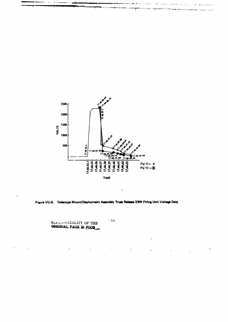
8/8/2019 MSFC Skylab Structures and Mechanical Systems Mission Evaluation
http://slidepdf.com/reader/full/msfc-skylab-structures-and-mechanical-systems-mission-evaluation 132/348
.
't! 1 .
....-.-_ _
2000
1500!/I
I-_n0
..,ooo _.,,,/&.,s' %,
1?._.3t. _917dl4.41$t 17:44:4_.39
TI_E
FigureVU-6. TelescopeMount/DeploymentAmemblyTrum Flem EBWFiringUnit VoltageData
'15I_.'-"_JIJUCIBILITY OF TI-_

8/8/2019 MSFC Skylab Structures and Mechanical Systems Mission Evaluation
http://slidepdf.com/reader/full/msfc-skylab-structures-and-mechanical-systems-mission-evaluation 133/348
I
I16
8/8/2019 MSFC Skylab Structures and Mechanical Systems Mission Evaluation
http://slidepdf.com/reader/full/msfc-skylab-structures-and-mechanical-systems-mission-evaluation 134/348
........ ............ ,....._......_......................................_......... ...........L ................ .L.....................i............ - ...................... .A......
_ ..........................................................,""'---"T .......... 1................._ ..................-'_"-"' ...........-"_
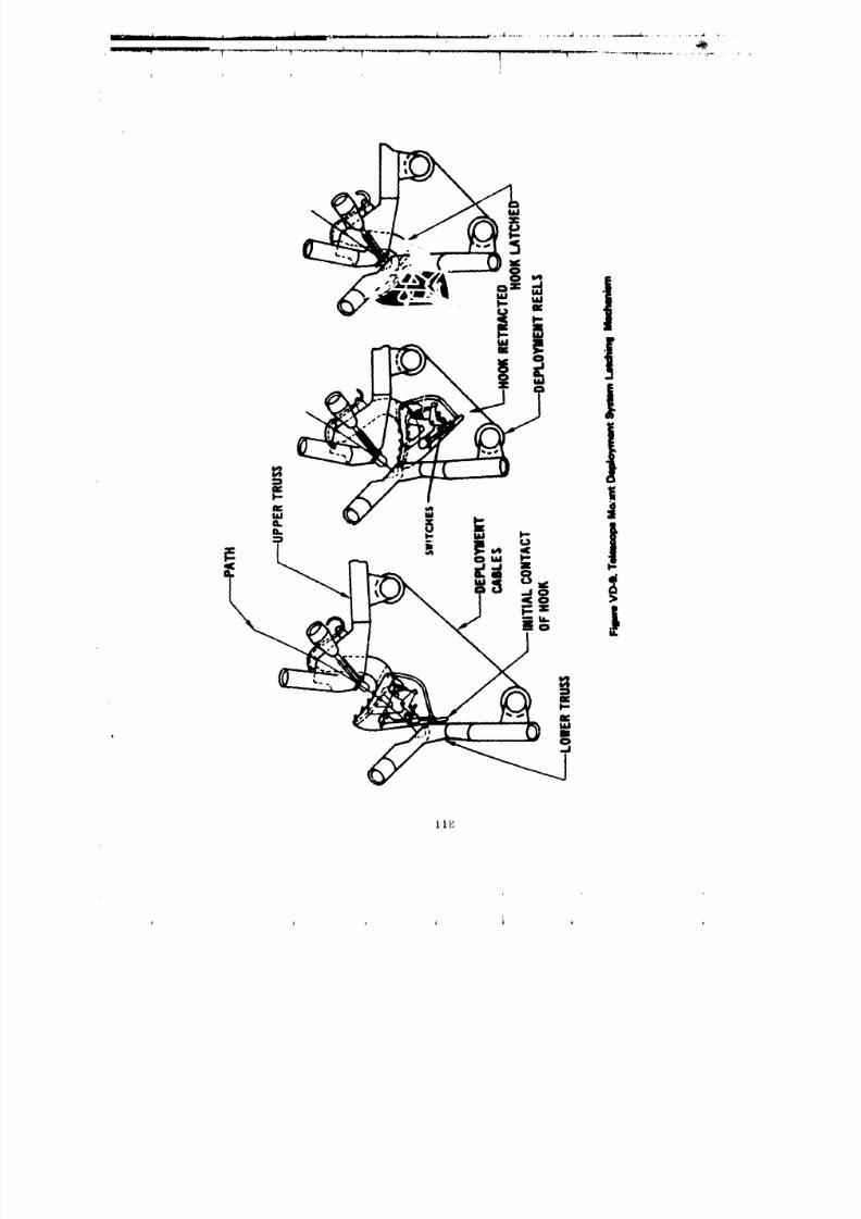
8/8/2019 MSFC Skylab Structures and Mechanical Systems Mission Evaluation
http://slidepdf.com/reader/full/msfc-skylab-structures-and-mechanical-systems-mission-evaluation 135/348
1 lg
I 1 i i i i •
8/8/2019 MSFC Skylab Structures and Mechanical Systems Mission Evaluation
http://slidepdf.com/reader/full/msfc-skylab-structures-and-mechanical-systems-mission-evaluation 136/348
and also removed the inhibit from the telescope mount solar array deployment
system.
The ground verification program on the deployment system was
quite extensive. Developmental tests with prototype 3tructure and flight-
type mechanisms verified design criteria of t=unnion spring _nd bearing
torques, cable loads and reel assembly torque capability, latching
mechanism geometry, and redundancy of deployment system components. Thirty-
four complete deployment cycles were run with the assembly in a horizontal
posi_tlcn. The mass of the upper truss assembly _nd telescope mount
simulator was subported on a cable pulley arrangement with cuunterbalance
to _imulate zero g in the i g environment. Individual component qualific,_ion
tests on the trunnion assembly, deployment reel assembly, and latching
mechanism demonstrated the capability _o operate satisfactorily ataltitlude under maximum loads at high (160 "F) and low (-65 "F) temperatures
after withstanding predicted flight vibration levels. A deployment assembly
qualification test was run on the first production assembly, built forthe vibroacoustics test, in the horizontal test setup using simulated
telescope mount mass and geometry. All mechanisms performed
c:orrectly and the time to deploy with both reel assemblies operating was
3 min 35.1 sec, which was well within the time allowed. A frozen bearing
test measured the torque zequired to rotate the bearing around the trunnion
bolt (3100 in.-Ib). This was well below 40,500 in.-lo min. stall torque of
the cable reel assembly. A complete deployment assembly was included in
the vibroacoustic test and tests were conducted with the deployment assembly
in the launch position inside the shrou_ and with the shroud removed
and the deployment assembly in the deployed position. There were no
anomalies with any of the deployment asq_mbly equipment. After analyzing
the vibrcacoustics data, it was determined that the deployment reel assembly
had been subjected to higher vibration levels than it had been qualified
for. Consequently, that unit was subjected to a complete acceptance
test to determine that no damage or performance degradation had occurred.
lhe flight unit was assembled vertically on the flight fixed airlock
shroud at the contractor's facility and then deployment functional tests were
run with each deployment reel assembly, and with bo=n reel assemblies
operating. The mass of the upper truss and telescope mount simulator
was counterbalance with a pulley and cable arrangement. Essentially
the same test was repeated wlth the same setup at KS_ prior to final
stacking.
Real time strip charts recorded at _FC showed that the deployment
_ystem performed flawlessly after kaunch and payload shroud separation.
Telemetry discrete signals indicating that voltage had been applied to
both deployment reel drive motors were received at 134:17:46:47.1 GMT,
LO sec after the deployment assembly release latch firing unit trigger
comman_ providing further verification that firing unit commands had beensent. Both switches on _he deployment assem01y latch mechanism operated
at 134:17:49:58.1, indicating that the upper and lower truss assemblies
were latched together. At 134:17:50:12.7, the voltage was ze_oved fromthe drive motors.
119
8/8/2019 MSFC Skylab Structures and Mechanical Systems Mission Evaluation
http://slidepdf.com/reader/full/msfc-skylab-structures-and-mechanical-systems-mission-evaluation 137/348
T!
E. Payload Shroud
1. Basic Requirements and Configuration Selection. The Payload
shroud (PS) provided an aerodynamic fairing for The Saturn Workshop
(SWS), structural support for the telescope mount, an environmental shield
with purge capability (to maintain positive internal pressure for protection
of enclosed modules), and a noncontamlnating separation and Jettison
system. From a variety of proposed configuration concepts, two
were selected for detailed separation capability evaluation: over-the-
nose and segmented. The over-the-nose concept was to be jettisoned
axially using thrusters. The basic configuration for this concept is
shown in figure VE-I. The segmented concept contained four 90 °
segments to be pyrotechnically severed and jettisoned laterally as shown
in figure VE-2. Both configurations were determined to be technically
feasible. The primary reason for selecting the segmented configuration
was pro&rammatic, based upon cost and schedule. Also, it had one potentialadvantage deserving mention for possible future application, but which
was never used; separation of the PS during ascent if required for
performance.
2. Payload Shroud Structures. The maximum weight allowable for
the payload shroud was 26,024 ib; weight at lift-off was 25,473 lb. Its
major structural assembly configuration is shown in Figure VE-3,
Skins on both nose cone sections were 0.250 in.-tnick 2024-T351
aluminam sheets wi_:h internal rings formed from 7075-T6 aluminum.
Lylinder skins were 2024-T351 aluminum, 0.375-in. thick on the lower
one-thlrd and 0.313-in. thick on the upper two-thirds. The cylinder
frames were formed from 7075-T73 aluminum I-beam extrusions and were
spaced approximately 23 in. apart.
Telescope mount loads were supported at 90° intervals on the forward
end of the ,:y]indrical suction. A support llnk, secured between fittings
l,yseml-cyllndrlcal slots, provided for attachment of the telescope mount
outrigger fittings through eccentrlu bushings with 0.125-in. radial
adjustment. Th s Jnstal£atlon is shown in FigurL VF-4. During payload
shroud Jzttison, movemenL of the support fittings at 45 ° to the axes of
the shroud released the telescope mount. The support llnk was designed
to remain attached to the telescope mount during subsequent orbital operations.
Figure VE-5 verifies the design by showing the ring still attached during
orbit.
a. Axial loads and bending moment. Except for a factor ofsafety uf 1.25 in the rebound direction for the telescope mount attach bolts,
Lhe payload shroud was designed to a factor of safety of 3.0 to eliminate
te_ting to ultimate load. The payload shroud was to support a telescope
mounf wei_h[ng 20,000 Jb mln. and 25,000 Ib max., and was to be
capable of withstanding [llsht, wind, handling, and separation system
ultimate loading without failure. Th_se requirements dictated that
120
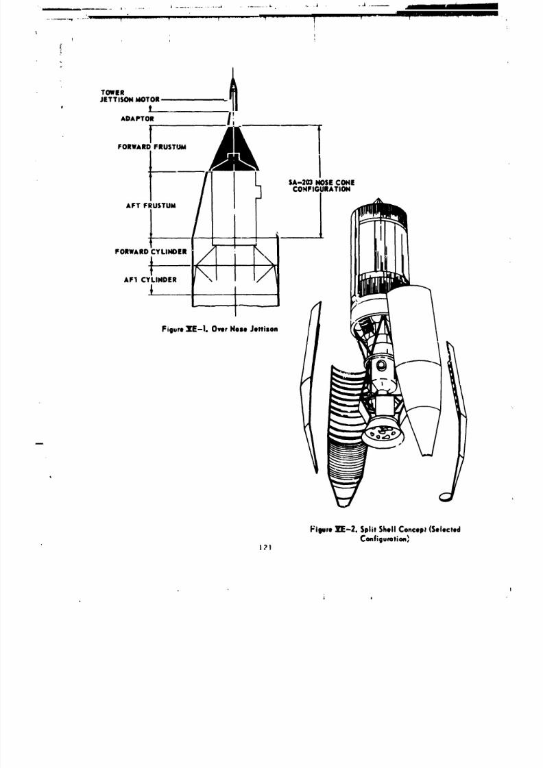
8/8/2019 MSFC Skylab Structures and Mechanical Systems Mission Evaluation
http://slidepdf.com/reader/full/msfc-skylab-structures-and-mechanical-systems-mission-evaluation 138/348
!
TOWER
JETTISON MOTOR ,, , --
, fADAPTOR I!
t yORWARDFRUSTUId
tCOHFIGURATION
AFT FRUSTUM
1 ' lFORWARDtCYLINDER _ I 'F1 CYLINDER I
Figure 1_-Io O_r Nes, Jettison
tt
Vioure lrF-2. Split Shell Concep_ (Selected
Configuration,_I?!
i
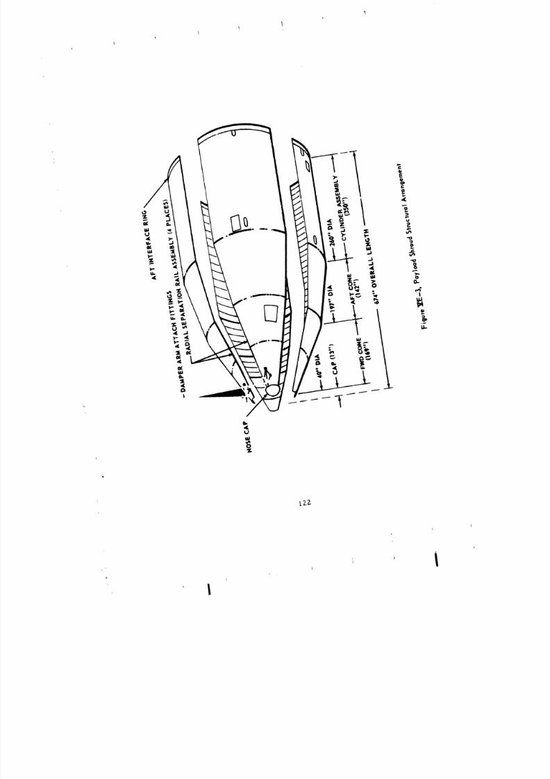
8/8/2019 MSFC Skylab Structures and Mechanical Systems Mission Evaluation
http://slidepdf.com/reader/full/msfc-skylab-structures-and-mechanical-systems-mission-evaluation 139/348

8/8/2019 MSFC Skylab Structures and Mechanical Systems Mission Evaluation
http://slidepdf.com/reader/full/msfc-skylab-structures-and-mechanical-systems-mission-evaluation 140/348
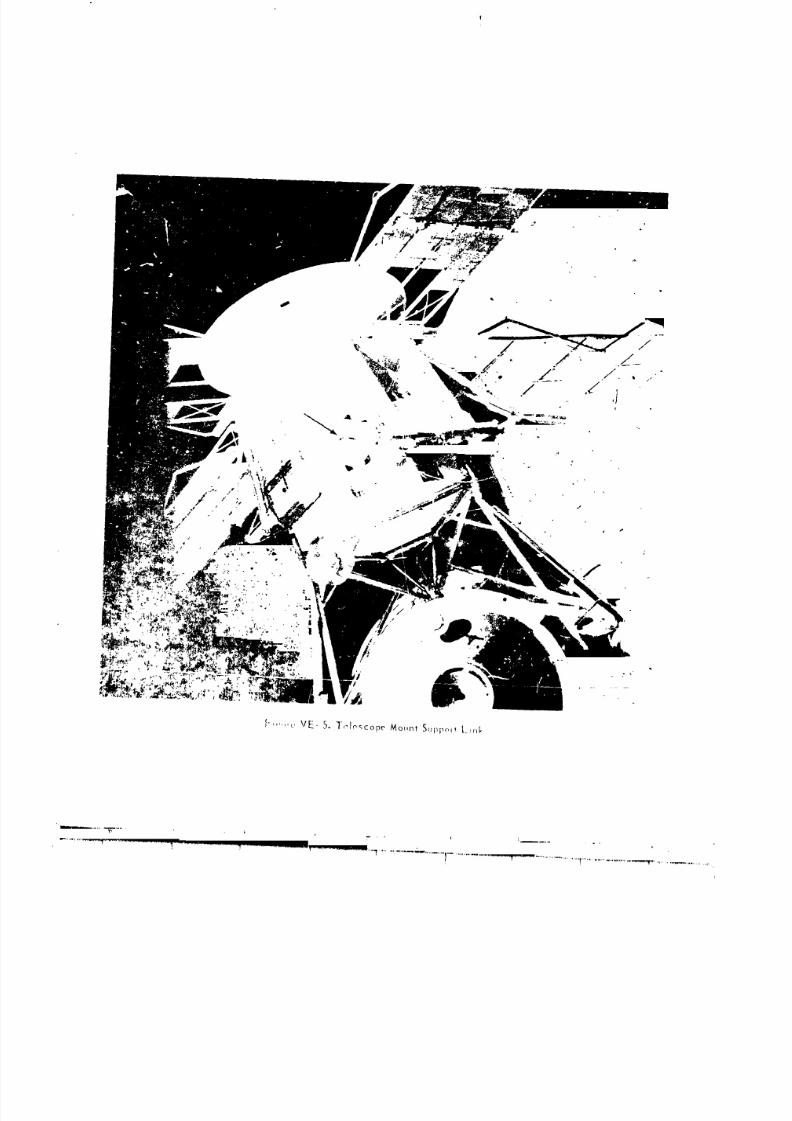
8/8/2019 MSFC Skylab Structures and Mechanical Systems Mission Evaluation
http://slidepdf.com/reader/full/msfc-skylab-structures-and-mechanical-systems-mission-evaluation 141/348
8/8/2019 MSFC Skylab Structures and Mechanical Systems Mission Evaluation
http://slidepdf.com/reader/full/msfc-skylab-structures-and-mechanical-systems-mission-evaluation 142/348
structural integrity analysis be accomplished in lieu of testing.
Structural analyses did verify the adequacy of the payload shroud to meet
all stress combinations defined for the useful life expectancy, including
the launch site. Stress measurements and calculations showed therealized factors of safety for the payload shroud to be 5.77 relative
to bending moment, and 3.24 in respect to axial compression loads.
b. Acoustical data. Vibroazoustical testing of the payload
_hroud was accomplished at the JSC. Modified input sound pressure levels and
acoustic criteria were used for the acoustical simulations in the enclosed
test area at the JSC. Test criteria and measured test results for
both the lift-off and boundary layer conditions are shown in Figure
VE-6. Payload shroud attenuation was adequate under the test conditions
and provided better attenuation than the specification required
during flight (Figure VE-7).
3. Natural Environments Design. Natural environments such as at-
mospheric temperature, humidity, particulate matter, rain, ground winds,
in-flight winds, radiation and meteoroids were considered in the design
of the payloa_ shroud. On the ground, the payload shroud protected the
internal equipnent from contamination by dust, rain, and wind. As shown
in Figure VE-8, the payload shroud contained a purge duct that inter-
faced to the pucge duct in the fixed airlock shroud. The combined ducts
provided class i00 air to a diffuser located 13 in. below the vehicle
tip. Tile diffused air maintained temperature, humidity, and cleanliness
for the entire payload shroud. Operation with conditioned air began
with the stacking of the telescope mount and continued until 30 min
prior to launch vehicle cyrogenic loading, _hen a nitrogen purge was
initiated through the ducts. The purge duc= system was designed to maintain
a flow rate of 50 +i0 Ib/min at a temperature of 63 +5 °F with
maximum duct internal p;essure of 1.5 psid. Evidence of hardware compliance
with the design is reflected in two Kennedy Space Center measurements:
(i) measurement CRT FR-09 shows the flow rates measured at the facility
outlet to be 6h to 68 lh/min during countdown demonstration test and
68 to 70 ib/min during launch (2) measurement 2C139, recorded on
the ,-nbillcal arm, shows the pressure to be 1.2 to 1.3 psig during test
and 1.3 pslg at launch. The Kennedy Space Center Skylab 1 Post-Launch
Report, RCS76-0000-O0048, states that all specifications for flow rates,
temperatures, and pressures were met, emd that flow/pressure was satisfactory
during the air to GN 2 changeover. There were no problems.
Protecthm to prevent wind-driven or falling rain and runoff from
punetrat[pg the interior of the payload shroud, while in a fully assembled
condition, at the KSC launch site was a requirement. During a rain stormat KSC the payload shroud leaked, apparently in the nose cap to nose
cone interface area. floweret, pinpointing the leak source was not definite.
125
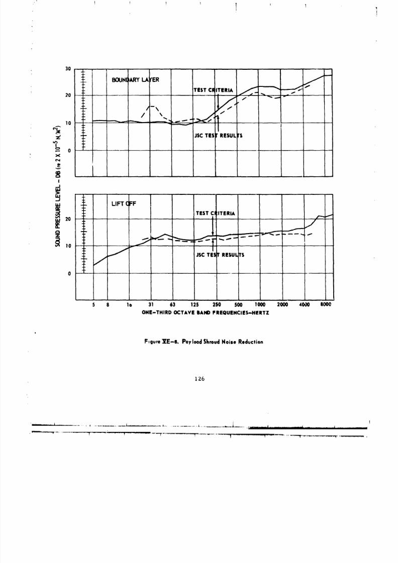
8/8/2019 MSFC Skylab Structures and Mechanical Systems Mission Evaluation
http://slidepdf.com/reader/full/msfc-skylab-structures-and-mechanical-systems-mission-evaluation 143/348
! ! ! 1 l
3O
20
/-\
:t_ i
-o
! ....vo / i sscTmrRESULTS
0 i b
1
L5 8 lo 31 63 125 250 SO0 1000 2000 4000 8000
ONE-THIRD OCTAVE BAND FREQUENCIES-HERTZ
F,gureVE-e. Payload SEroudNoise Reduction
IZ6
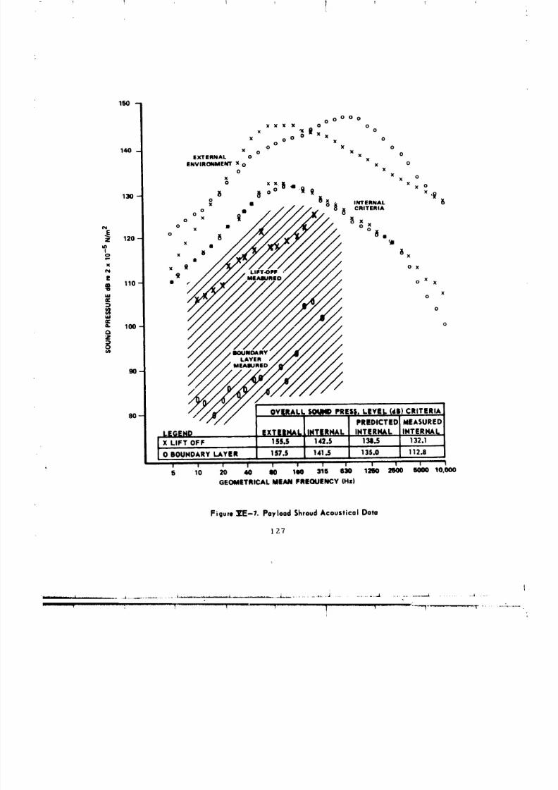
8/8/2019 MSFC Skylab Structures and Mechanical Systems Mission Evaluation
http://slidepdf.com/reader/full/msfc-skylab-structures-and-mechanical-systems-mission-evaluation 144/348
! 1 !, T 1
150 -
O O O O OX X X X O O
X 'X _ O
x o o 0 x x oo x
*0 X 0140- x o x
EXTERNAL O x OxENVIRONMENT ,x o x o
O xx ox x
o xx_,i x
13o _ _ oo ._ _ x oO _ X INTERNAL
o Io
o _ _ _xx
e_ 0 x • °o_ iI120 - o _Ix
in •
°o , " _xw- I
x x g ox
P _ x110 - • ,- o x
xIAI 0m
_ °w
100 o
_m
8O-PREDICTED MEASURED
L.EGEND EXTEINALI,INT|RNAL INTERHAL INTERNAl._X LIFT OFF 155,5 142,5 138,5 132.1
I i
O BOUNDARY LAYER 157.5 141.5 135.0 112.8I
I I I I I I I i I I ' I I I
5 10 20 40 lO 1110 316 830 12110 2SO0 SO00 10,000
GEOMETRICALMEAN FREOUENCY (Hz)
Figure ][E-7. Payload ShroudAcoustical Data
127

8/8/2019 MSFC Skylab Structures and Mechanical Systems Mission Evaluation
http://slidepdf.com/reader/full/msfc-skylab-structures-and-mechanical-systems-mission-evaluation 145/348
1 I I ! _ 1I
13.0 I,.
STAo4012.961
-'f; DIFFUSERPPER DUCT
l "r _ INTERMEDIATE DUCT
ATM
FIELD JOINT DUCTPAYLi lADSHROUD _ . LOWERDUCT
MDA
,, t" _/"__ CROSSVeRDUCT.. ,,A.s,,,ouc,
.,.,,,..o.ou:,r
F S _ INTERFACE BRACKETFA$ PURGEDUCT
m,, UMBILICAL PLATE_u
Figure _'E- 8. Payload Shroud/Fixed Airlock ShroudPurgeDuct Routing
!2B
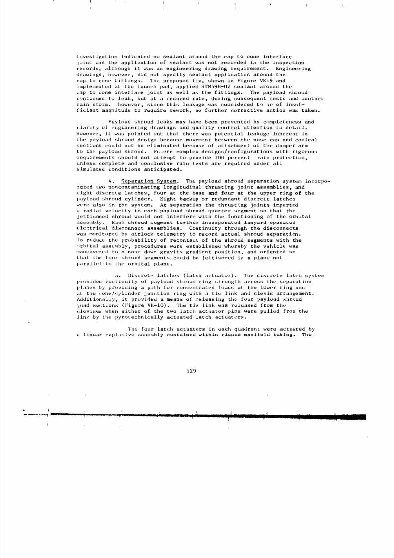
8/8/2019 MSFC Skylab Structures and Mechanical Systems Mission Evaluation
http://slidepdf.com/reader/full/msfc-skylab-structures-and-mechanical-systems-mission-evaluation 146/348
Investigation indicated no sealant around the cap to cone interface
joint and the application of sealant was not recorded ia the inspection
records, although it was an engineering drawing requirement. Engineering
drawings, however, did not specify sealant application around the
cap to cone fittings. The proposed fix, shown in Figure VE-9 and
hnplemented at the launch pad, applied STM598-02 sealant around the
cap to cone interface joint as well as the fittings. The payload shroud
continued to leak, but at a reduced rate, during subsequent tests and another
rain storm. Itowever, since this leakage was considered to be of insuf-
ficiant magnitude to require rework, no further corrective action was taken.
Payload shroud leaks may have been prevented by completeness and
clarity of engineering drawings and quality control attention to detail.
However, it was pointed out that there was potential leakage inherent in
the payload shroud design because movement between the nose cap and conical
sections could not be eliminated because of attachment of the damper arm
to the payload shroud. Fu.ure complex designs/configurations with rigorous
requirements should not attempt to provide i00 percent rain protection,
unless complete and conclusive rain tests are required under all
simulated conditions anticipated.
4. Separation System. The payload shroud separation system incorpo-
rated two noncontaminating longitudinal thrusting joint assemblies, and
eight discrete latches, four at the base and four at the upper ring of the
payload shroud cylinder. Eight backup or redundant discrete latches
were also in the system. At separation the thrusting joints imparted
a radial velocity to each payload shroud quarter segment so that the
jettisoned shroud would not interfere with the functioning of the orbital
assembly. Each shroud segment further incorporated lanyard operated
electrical disconnect assemblies. Continuity through the disconnects
was monitored by airlock telemetry to record actual shroud separation.To reduce the probability of recontact of the shroud segments with the
urbita] assembly, procedures were established whereby the vehicle was
maneuvc;red to a nose down gravity gradient position, and oriented so
that the four sllroud segments couJd be jettisoned in a plane not
parallel to the orbital plane.
;i. Discrete latches (latch actuator). The discrete latch sy<item
provided continuity of p,lyload shroud ring strength across the separatLon
pl;inus by providing a path for concentrated loads at the lower ring and
at the cone/cylinder junction ring with a tie link and clevis arrangement.
Additionally. it provided a means of releasing the four payload shroud
quad suctions (Figure VE-IO). The tie link was released from the
clevises when either of the two latch actuator pins were pulled from the
linl, by the pyrotechnically actuated latch actuators.
The four latch actuators ill each quadrant were actuated by
a linear explosive assembly contained within closed manifold tubing. The
129
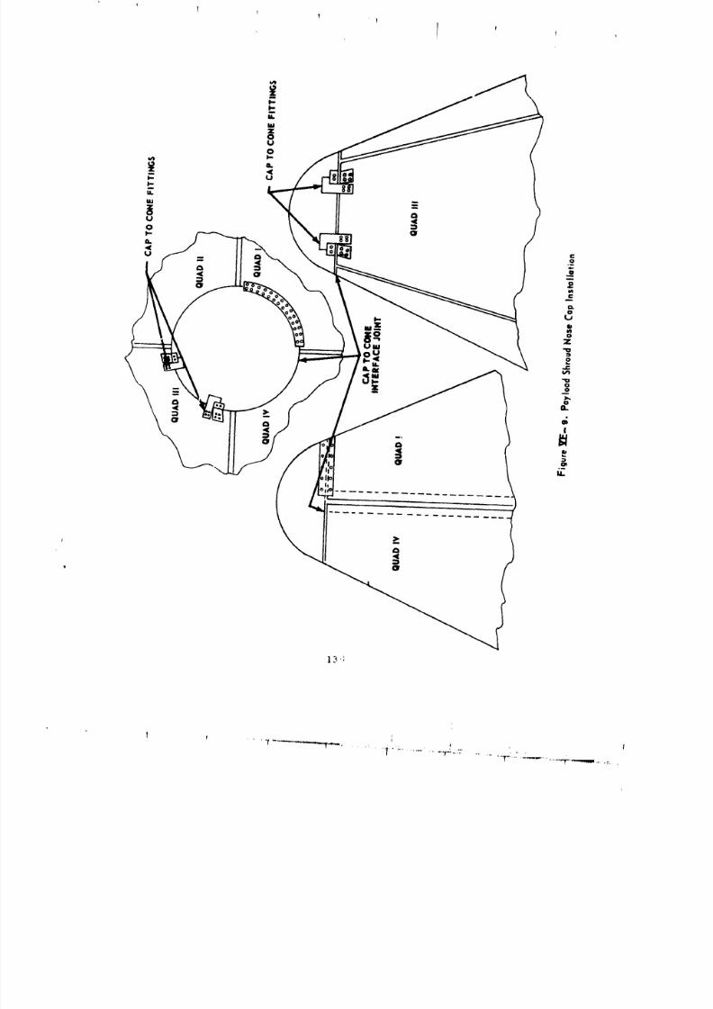
8/8/2019 MSFC Skylab Structures and Mechanical Systems Mission Evaluation
http://slidepdf.com/reader/full/msfc-skylab-structures-and-mechanical-systems-mission-evaluation 147/348
1 ft
!
I
13 ':
I
_r"_--_-._., .... ,'"'..............."mml
Uq
.,-_..7.......... . _ _ ,,,-,,,.

8/8/2019 MSFC Skylab Structures and Mechanical Systems Mission Evaluation
http://slidepdf.com/reader/full/msfc-skylab-structures-and-mechanical-systems-mission-evaluation 148/348
i L
8/8/2019 MSFC Skylab Structures and Mechanical Systems Mission Evaluation
http://slidepdf.com/reader/full/msfc-skylab-structures-and-mechanical-systems-mission-evaluation 149/348
I I I ! I ,J
linear explosive assembly was detonated by exploding bridgewire detonators
at each end of the manifold to provide redundancy. The detonators
were initiated by exploding bridgewire firing units, with one firing
unit for each assembly, powered from airlock electrical bus #I and theother from bus #2. Each exploding bridgewire firing unit was programmed
to receive redundant charge and fire commands, spaced 0.2 sec apart,
from the instrument unit switch selector. An alternate means of initiation
was available from the airlock digital con_nand system, hut was
not needed.
Operation of the discrete latch system was demonstrated through
numerous ground tests. The exploding bridgewire detonator confinement and
propagation tests were conducted on 26 test specimens, representative
of flight hardware, to demonstrate proper confinement of the explosion
products and the propagation of detonation under conditions more adverse
that encountered in-fllght. Verification tests at MDAC-E on four full-
scale fllght-type latch actuators, representing one-fourth of the vehicle
system, demonstrated operation of the latch actuators when exposed to
conditions of temperature (-20 to 160 °F), loading (0 ":o 333 percent
of nominal side load), and explosive charge (50 to 150 percent
of nominal) after exposure to anticipated flight vibration levels.
in three full-scale altitude chamber separation system tests run at
Plum Brook, Ohio, the latch actuators (16) also operated within the
conditions stated above. One quadrant (quad IV) was then equipped with
a full complement of ordnance components to be fired subsequent to
the vlbroa:oustics test to be run at the JSC. It was successfully
fired (one detonator only) after the conclusion of the vibration
and acoustic tests. The other detonator, not connected to the power
clrc,,it, was sympathetically fired by the linear explosive.
The payload shroud discrete latch exploding bridRewire firing unit
charge and trigger voltages were monitored during flight to verify
sequences. The progral_ed sequence was: (i) charge co,and given, (2)
5.02 sec later the trigger or fire con_nand given, and (3) 5 sec later
unit reset. Compressed computer printout data of these measukements
indicate that all eight of the latch firing units were in a charged
condition by [34:17:43:14.01 and that all eight units had triggered by
134:12:43:14:81. While it has not been possible to re,zoncile progran_med
charge and trigger times with the times displayed for actual voltage
puint_ in the computer printout, a plot of the firiLlg unit charge, trigger,
and reset voltage is normal when compared with plots of the ground
tests for like firlug units. A typical plot of the firing unit charge
a,d trigger voltage, constructed from a real time strip chart recording
with tilnes e_tabllshed by computer printout data, is shown in Figure VE-II.
b. Ti_rusting Joint. The two noncontaminatlng tl_rusting joint
a_emblies, located in the longitudinal separation planes between the
payload shr_ud quadrants, consisted of a linear cylinder and piston
riveted together tu form a rail assembly. These joints provided the force
132
ii
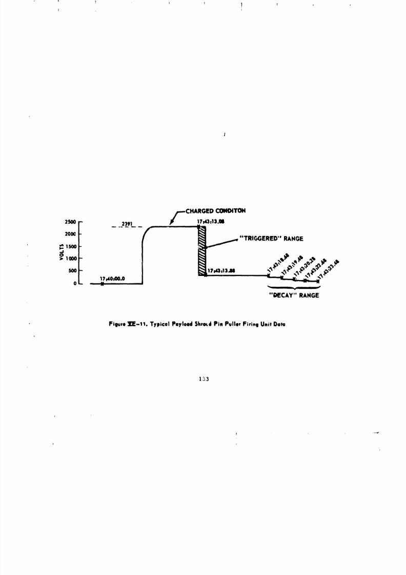
8/8/2019 MSFC Skylab Structures and Mechanical Systems Mission Evaluation
http://slidepdf.com/reader/full/msfc-skylab-structures-and-mechanical-systems-mission-evaluation 150/348
l I 1 l t T!
2S00r 23.91 P/=--CHARGEDI7_l'I3"MCONDITOH
2o0ot" "TRIGGERED" RAHGE
OL-v
"DECAY" RANGE
Figure IE-11. Typical Payload Shrc_dPin Puller Firing Unit Ooto
1_3
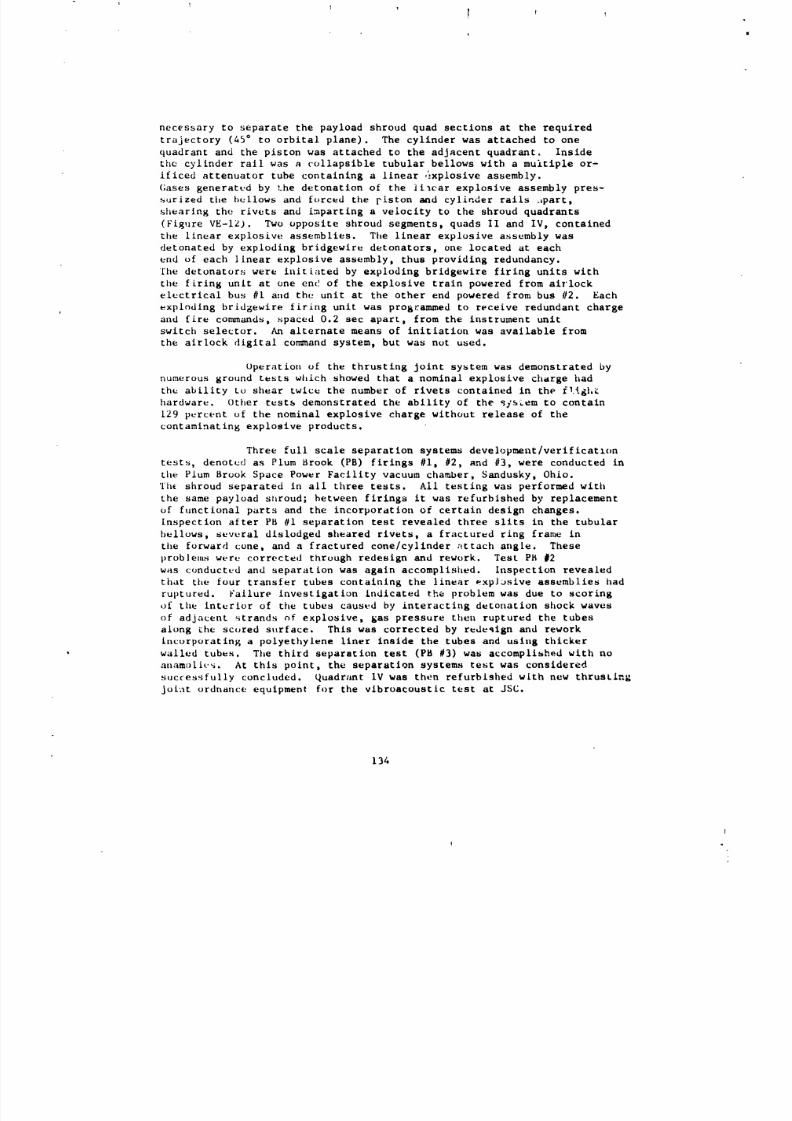
8/8/2019 MSFC Skylab Structures and Mechanical Systems Mission Evaluation
http://slidepdf.com/reader/full/msfc-skylab-structures-and-mechanical-systems-mission-evaluation 151/348
0
necessary to separate the payload shroud quad sections at the required
trajectory (45 ° to orbital plane). The cylinder was attached to one
quadrant and the piston was attached to the adjacent quadrant. Inside
the cylinder tall was a collapsible tubular bellows with a multiple or-
ificed attenuator tube containing a linear ,_xplosive assembly.
Gases generated by the detonation of the _i_car explosive assembly pres-
surized the bellows and forced the piston and cylinder rails .Lpart,
shearing the rivets and imparting a velocity to the shroud quadrants
(Figure VE-12). Two opposite shroud segments, quads II and IV, contained
the linear explosive assemblies. The linear explosive assembly was
detonated by exploding bridgewlre detonators, one located at each
end of each linear explosive assembly, thus providing redundancy.
The detonators were initiated by exploding bridgewire firing units with
the firing unit at one end of the explosive train powered from airlock
electrical bus #I and the unit at the other end powered from bus #2. Each
exploding bridgewire firing unit was programmed to receive redundant charge
and fire commands, spaced 0.2 sec apart, from the instrument unit
switch selector. An alternate means of initiation was available from
the airlock digital con_and system, but was not used.
Operation of the thrusting Joint system was demonstrated by
numerous ground tests which showed that a nominal explosive chdrge had
the ability to shear twice the number of rivets contained in the f!tg|,_
hardware. Other test_ demonstrated the ability of the _ys_em to contain
129 percent of the nominal explosive charge without release of the
contaminating explosive products.
Three full scale separation systems development/verificatlon
tests, denoted as Plum Brook (PB) firings #I, #2, and #3, were conducted in
the Plum Brook Space Power Facility vacuum chamber, Sandusky, Ohio.
The shroud separated in all three tests. All testing was performed with
the same payload shroud; between firings it was refurbished by replacement
of functional parts and the incorporation of certain design changes.
[nspectlon after PB #i separation test revealed three slits in the tubular
bellows, several dislodged sheared rivets, a fractured ring fran_ in
the forward cone, and a fractured cone/cylinder attach angte. These
problems were corrected through redesign and rework. Test PB #2
was conducted and separation was again accomplished, inspection revealed
that the four transfer tubes containing the linear _xpJJslve assemblies had
ruptured. Failure investigation indicated the problem was due to scoring
of the interior of the tubes caused by interacting detonation shock waves
of adjacent _trands of explosive, gas pressure then ruptured the tubes
along _he scored surface. This was corrected by redeqlgn and rework
incorporating a polyethylene liner inside the tubes and using thicker
walled tubes. The third separation test (PB #3) was accomplished with no
anamol[¢_. At thls point, the separation systems test was considered
successfully concluded. Quadrant IV was then refurbished with new thrusLing
joint ordnance equipment for the vlbroacoustlc test at JSC.
134
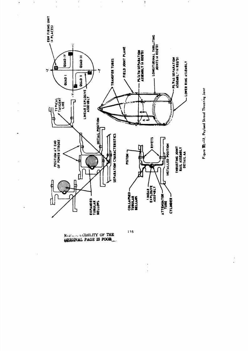
8/8/2019 MSFC Skylab Structures and Mechanical Systems Mission Evaluation
http://slidepdf.com/reader/full/msfc-skylab-structures-and-mechanical-systems-mission-evaluation 152/348
' Ii
R_.,i,.....,t;lilll,IZ OP TIIII
!
i
I
8/8/2019 MSFC Skylab Structures and Mechanical Systems Mission Evaluation
http://slidepdf.com/reader/full/msfc-skylab-structures-and-mechanical-systems-mission-evaluation 153/348
1 1 1 1 l
No proDlems were encountered during or after this test. The thrusting
linear explosive assembly was removed from the shroud after the vibro-
acoustic test and subjected to detonation velocity tests. The
detonatlon velocity was above the 18,000 ft/sec minimum allowed,indicating that the explosive assembly was not affected by the vibration
or the acoustic environments. A rail assembly for the vibroacoustic
test shroud was refurbished at Plum Brook with new equipment and subjected
tu a lO-month aging/vibration test to demonstrate that the thrusting
joint syste_ was not affected by shelf life/storage and e>.posure during
vibroacoustic testing. The aging portion of the test was terminated at
iO months and the test was considered successfully concluded.
One major anomaly occurreJ in the payload shroud linear explosive
assembly that was discovered during a KSC inspection prior to launch.
The :ayload _hroud separation system used long (97 and 122 ft)
linear oxplosive assemblies (Primaline) to develop the pressure for
operation of the discrete latches and for inflation of the bellows in
the thrusting joint. During the KSC inspection it was discovered that
shrinkage of the Primaline had occurred with an average shortening of
3.9 in. per i00 ft over a 3-month period. This was 1.4 in.
l_:ss than the minimum installable length, therefore, a serious installation
proble,n was created. However, since MSFC had no previous component
(Primaline) experience and shrinkage had not been a problem up to this
point, it was not a design consideration. An investigation revealed
that thu shrinkage was induced by both time and temperature
and that it was accelerated by high ambient temperatures (e.g., 120 °F
transport and storage). To correct the problem a new Primaline assembly
was fabricated and additional design requirements imposed to control
shrinkage, which includ_d thermal conditioning of all new Primaline at
125 +5 °F for 2 wk to preshrink it. Also, an 80 °F maximum tem-
perature during manufacturing and 50 °F maximum temperature during shipmentand storage were imposed. Observallce of these constraints resolved the
shrinkage problem; shrinkage was estin,ated to be approximately 0.5 in.
per i00 over a 3-month period. This was well within the 2.5 in.
required for a minimum installable _ength.
Evaluation of the flight payload shroud thrusting joint
u×ph,ding bri<Igewire firing unit voltages and command times indicated a
normal function of all four firing units in this system, as compared with
plot_ of ground test firiags of like units.' This is further confirmed by
t!:_ time indicated for lanyard disconnect. Note that _t the time of disconnect
thu tul,'metry and power circuits were opened an_i reset of the firing unit
was not pos:.Lble. A typical payload shroud thrusting joint charge
,lld tL[gger p[ot is _hown in Figure _._-13. The time and data points for
thi._ plot wuru taken from compressed computer printout data. This operation
was also verified by real time strip charts recorded at MSFC.
136
........ , i .... _ ........ _.......................... i................ L,,.i ................ a ...... _ ..........................II
8/8/2019 MSFC Skylab Structures and Mechanical Systems Mission Evaluation
http://slidepdf.com/reader/full/msfc-skylab-structures-and-mechanical-systems-mission-evaluation 154/348
1
2500 -- 2420 u .-"TRIGGERED" RANGE
2000-
_,,1500 -I,-.J
>o1000 - 17t4St20,67I ,
500- I s
17:43.55.88 ,17:4_: 22
0 - I LANYARD DISCONNECT
Figure VE-13. Typical Payload ShroudThrusting Joint EBWFiring Unit
]37
8/8/2019 MSFC Skylab Structures and Mechanical Systems Mission Evaluation
http://slidepdf.com/reader/full/msfc-skylab-structures-and-mechanical-systems-mission-evaluation 155/348
MSFC has identified four objects from the NORAD tracking dat_
to be the four payload shrouo segments. Using orbital mechanics to ex--
trapolate backwards from the NORAD reported orbits, the direction and minimum
velocity at which the objects departed Skylab has been determl _d to be
(Table VE-I):
TABLE VE-I. SEPARATION DATA
Satellite no. Minimum Separation
in Orbital Plane
6637 14 ft/sec Retrograde 19.8 ft/sec
6638 12 ft/sec Posigrade i_.0 ft/sec
6643 ii ft/sec Retrograde 15.6 ft/sec
6651 13 ft/sec Posigrade 18.4 ft/sec
Separation values in Tab_ VE-I compare very favorably with results of
the three separation tests conducted at Plum Brook, Ohio, where measured
segment velocities varied from 16 to 19 ft/sec, thus ipdicating
the shroud jettisoning was nominal.
_. Contamination. V_rification that products of detonation
(explosion) were contained by the flight unit was not possible since
the shroud disconnected from the orbital assembly upon separation. However,
ground tests did demonstrate this capability on the test units, and no
indication of major separation contamination was reported. Data from
the Quartz Crystal Microbalancer (contamination measurements) did indicate
a major reduction of contamination on the crystal surfaces immediately
upon achieving orbit (Figure VE-14). Thus, it can be concluded that no
detectable contaminants were released by the payload separation system.
5. Conclusions and Lessons Learned. Specifications and criteria
governing payload shroud design and performance were adequate. Payload
shrou_ pc_rformance other than leakage on the launch pad because of rain was
satisfactory. Future designs of this type should ensure that shroud/
facility interfaces preclude movement at the attaching Joint to prevent
internal contamination by rain or particulate matter. Sealants and their
application should be more closely monitored, and verified prior to exposure
of hardware to uncontrollable environments, Primaline shrinkage, as a
factor of temperatures and time (reference paragraph 4b, this section)
is an important lesson to be applied to futur_ designs incorporating
long lengths of this material.
138
J J j
8/8/2019 MSFC Skylab Structures and Mechanical Systems Mission Evaluation
http://slidepdf.com/reader/full/msfc-skylab-structures-and-mechanical-systems-mission-evaluation 156/348
i . I • • • I i I , l I I I l , I I I J I I
"" *" "" "=" I |
$.L'IO^
139
i I i _ j
8/8/2019 MSFC Skylab Structures and Mechanical Systems Mission Evaluation
http://slidepdf.com/reader/full/msfc-skylab-structures-and-mechanical-systems-mission-evaluation 157/348
i
F. Docking Adapter
i. Basic Requirements and Configuration Evolution. The docking
adapter structure is required to provide: A pressurized passageway betweenthe airlocL and the docked command and service module; two docking interfaces;
stowage for hardware and experiments, support for experiments and control
consoles; and, prelaunch purge and ascent and orbital venting of the airlock
and docking adapter.
Initially, under the wet workshop concept, the docking adapter was
was designed with five docking ports for the command and service modules,
tile lunar module/telescope mount, and resupply modules. A scientific airlock
and various experiments were to be permanently installed and gridwork
panels were to provide launch mountings for equipment to be transferred to
the spent S-IVB stage by the crew on-o[bit. After tile stowed equipment
was transferred to the worksilop, the docking adapter would become a work
area. During design evolution, three docking ports were eliminated, but
the wet workshop shell was retained and extensi._e internal changes were made
when the dry workshop concept was adopted. External views of both con-
figurations are provided in Figure VF-I.
TI_u dry workshop allowed experiments and equipment previously
planned for launch in the docking adapter to be permanently installed in
the workshop. The docking adapter became available for additional permanent
installations including the telescope mount film vaults, the materials
processing facility, the S009 experiment, a viewing window, and various
containers. The scientific airlock was relocated to the workshop. Figure
VF-2 :_hows how structural ring frames and longeron splice plates were added
internally to the docking adaptez to take the high local loads resulting
from changed requirements.
Thu addition of earth resources/observation e×periments required
in';tallation _f three experLments on the earth-facing side of tile decking
;_dapter. Exi)eriments Slgl and $192 are installed with portions internal
and sensors protruding from cutouts in the docking adapter skin. The S194
l,-l)andqntenna, the proton spectrometer, and the telescope mount inverter/
ligi_ting control assembly are mounted un a truss at the cone end of the
docking adapter, l'he earth-vlewing wiildow was upgraded in optical quality
ior usu wit', the El90 experiment. An external view of these installations
;s prov_deJ in Figure VF-I.
During installaLiun, checkuut, and test phases, other requirements
were [dcutlfiud, including tools for in-flight maintenance and potential
continguqcles. A three drawer tool box for standard toolsand a (ontaim,r for hatch contln_ency tools were designed. The standard
t,._l ¢:,mtainer is m(u,ntud inturnally and the contingency tool container
i,'_ nl,),Jii[4_.(I ('xturn.iI ly oll tile axial ll;lt('h.
[40
L
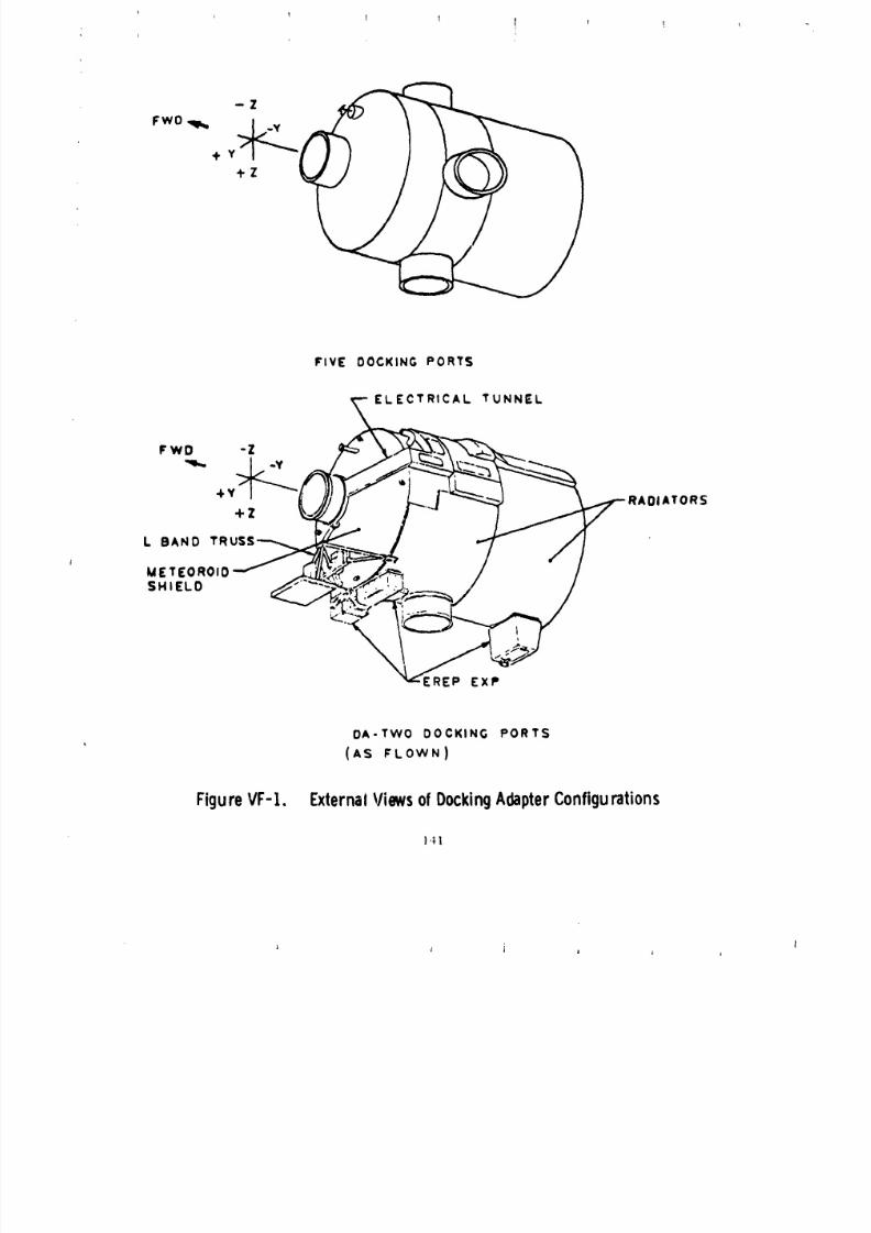
8/8/2019 MSFC Skylab Structures and Mechanical Systems Mission Evaluation
http://slidepdf.com/reader/full/msfc-skylab-structures-and-mechanical-systems-mission-evaluation 158/348
! |j
-Z
FwO _ +Z
FIVE DOCKING PORTS
ELECTRICAL TUNNEL
FWD -Z
•Y OlATORS+Z
L BAND TR
METEOROIDSHIELO
EREP EXP
DA-TWO DOCKING PORTS
(AS FLOWN)
FigureVF-t. ExternalViewsofDockingAdapterConfigurations
141
J i i I _ i
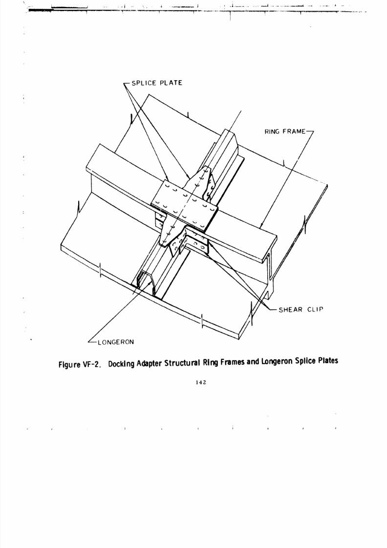
8/8/2019 MSFC Skylab Structures and Mechanical Systems Mission Evaluation
http://slidepdf.com/reader/full/msfc-skylab-structures-and-mechanical-systems-mission-evaluation 159/348
SPLICE PLATE
RING FRAME-- 7
/
SHEAR CLI P
LONGERON
FigureVF-2. DockingdapterStructuralRingFramesndLongeronplicePlates
142
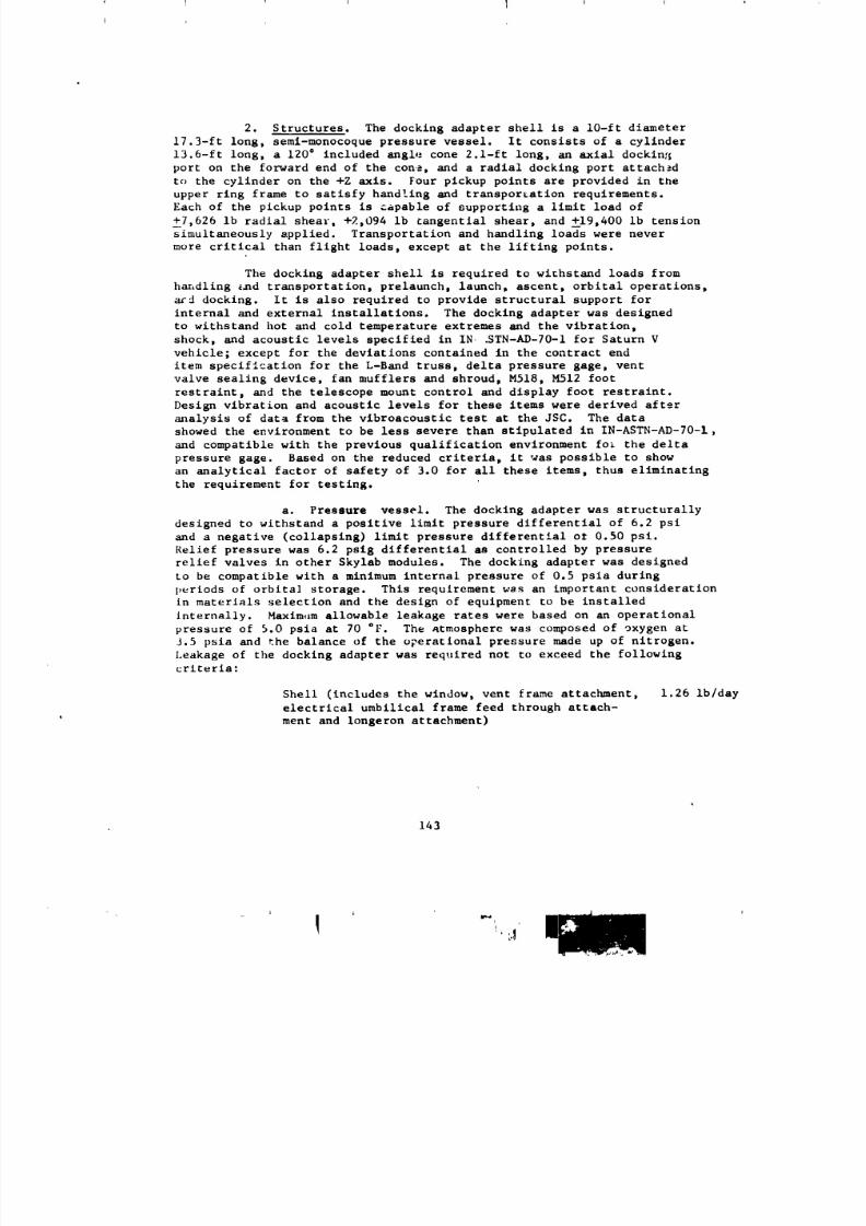
8/8/2019 MSFC Skylab Structures and Mechanical Systems Mission Evaluation
http://slidepdf.com/reader/full/msfc-skylab-structures-and-mechanical-systems-mission-evaluation 160/348
2. Structures. The docking adapter shell is a lO-ft diameter
17.3-ft long, semi-monocoque pressure vessel. It consists of a cylinder
13.6-ft long, a 120 ° included angle cone 2.l-ft long, an axial docking
port on the forward end of the cone, and a radial docking port attachedto the cylinder on the +Z axis. Four pickup points are provided in the
upper ring frame to satisfy handling and transporeation requirements.
Each of the pickup points is capable of supporting a limit load of
_7,626 ib radial shear, +2,094 ib tangential shear, and _19,400 ib tension
simultaneously applied. Transportation and handling loads were never
more critical than flight loads, except at the lifting points.
The dockln 8 adapter shell is required to withstand loads from
handling _md transportation, prelaunch, launch, ascent, orbital operations,
ard docking. It is also required to provide structural support for
internal and external installations. The docking adapter was designed
to withstand hot and cold temperature extremes and the vibration,
shock, and acoustic levels specified in IN .STN-AD-70-1 for Saturn V
vehicle; except for the deviations contained in the contract end
item specification for the L-Band truss, delta pressure gage, vent
valve sealing device, fan mufflers and shroud, M518, M512 foot
restraint, and the telescope mount control and display foot restraint.
Design vibration and acoustic levels for these items were derived after
m_alysis of data from the vlbroacoustic test at the JSC. The data
showed the environment to be less severe than stipulated in IN-ASTN-AD-70-1,
and compatible with the previous qualification environment fo_ the delta
pressure gage. Based on the reduced criteria, it was possible to show
an analytical factor of safety of 3.0 for all these items, thus eliminating
the requirement for testing.
a. Pressure vessel. The docking adapter was structurally
designed to withstand a positive limit pressure differential of 6.2 psi
and a negative (collapsing) limit pressure differential ot 0.50 psi.
Relief pressure was 6.2 pslg differential as controlled by pressure
relief valves in other Skylab modules. The docking adapter was designed
to be compatible with a minimum internal pressure of 0.5 psia during
periods of orblta] storage. This requirement was an important consideration
in materials selection and the design of equipment to be installed
Internally. Maxim,lm allowable leakage rates were based on an operational
pressure of 5.0 psia at 70 °F. The atmosphere was composed of oxygen at
J.5 psia and the balance of the operational pressure made up of nitrogen.
Leakage of the docking adapter was required not to exceed the following
criteria:
Shell (includes the window, vent frame attachment, 1.26 Ib/day
electrical umbilical frame feed through attach-
ment and longeron attachment)
143
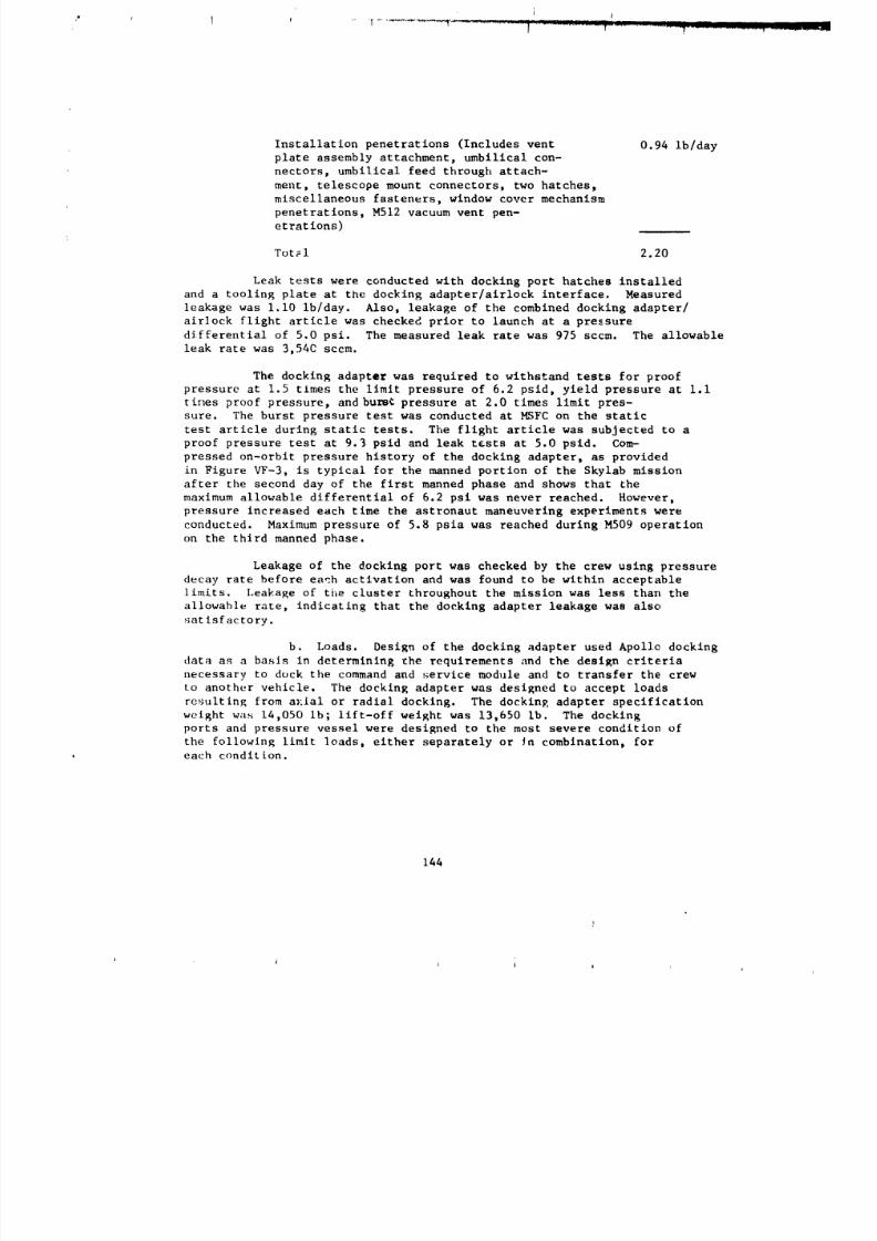
8/8/2019 MSFC Skylab Structures and Mechanical Systems Mission Evaluation
http://slidepdf.com/reader/full/msfc-skylab-structures-and-mechanical-systems-mission-evaluation 161/348
Installation penetrations (Includes vent 0.94 ib/day
plate assembly attachment, umbilical con-
nectors, umbilical feed through attach-
ment, telescope mount connectors, two hatches,
miscellaneous fasteners, window cover mechanism
penetrations, M512 vacuum vent pen-
etrations)
Tot_l 2.20
Leak tests were conducted with docking port hatches installed
and a tooling plate at the docking adapter/airlock interface. Measured
leakage was i.i0 ib/day. Also, leakage of the combined docking adapter/
airlock flight article was checked prior to launch at a pressure
differential of 5.0 psi. The measured leak rate was 975 sccm. The allowable
leak rate was 3,540 sccm.
The docking adapter was required to withstand tests for proof
pressure at 1.5 times the limit pressure of 6.2 psid, yield pressure at i.i
times proof pressure, andbums£ pressure at 2.0 times limit pres-
sure. The burst pressure test was conducted at MSFC on the static
test article during static tests. The flight article was subjected to a
proof pressure test at 9.3 psid and leak tests at 5.0 psid. Com-
pressed on-orbit pressure history of the docking adapter, as provided
in Figure VF-3, is typical for the manned portion of the Skylab mission
after the second day of the first manned phase and shows that the
maximum allowable differential of 6.2 psi was never reached. However,
pressure increased each time the astronaut maneuvering experiments were
conducted. Maximum pressure of 5.8 psla was reached during M509 operation
on the third manned phase.
Leakage of the docking port was checked by the crew using pressure
decay rate before each activation and was found to be within acceptable
limits. Leakage of the cluster throughout the mission was less than the
allowable rate, indicating that the docking adapter leakage was also
satisfactory.
b. Loads. Design of the docking adapter used Apollo docking
data as a basis in determining the requirements and the design criteria
necessary to duck the command and service module and to transfer the crew
to another vehicle. The docking adapter was designed to accept loads
resulting from a_:ial or radial docking. The docking adapter specification
weight was 14,050 lb; lift-off weight was 13,650 lb. The dockin K
ports and pressure vessel were designed to the most severe condition of
the following limit loads, either separately or Jn combination, for
each condition.
144
l li i i
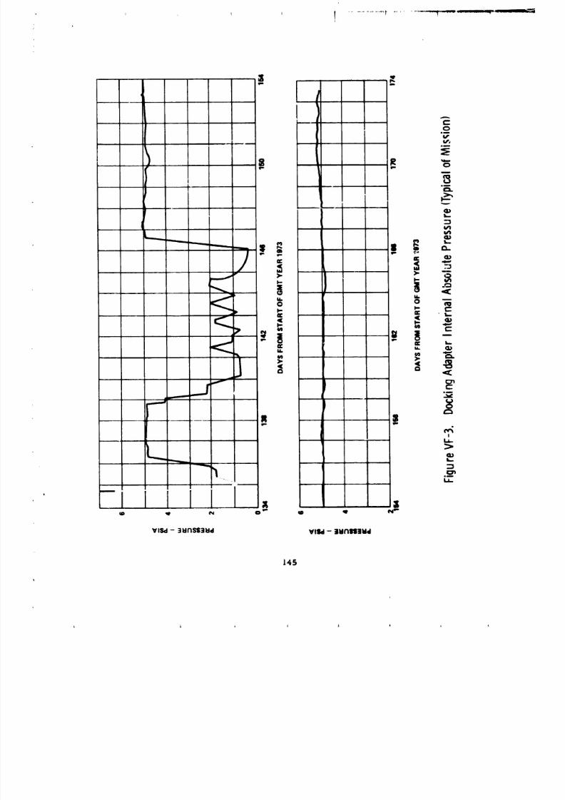
8/8/2019 MSFC Skylab Structures and Mechanical Systems Mission Evaluation
http://slidepdf.com/reader/full/msfc-skylab-structures-and-mechanical-systems-mission-evaluation 162/348
/
c-C_om
8m
S le
I
-' >" i i
J i -*.__._.S_- t o_
- II l
!
Gl
.__
UD q' Oi 0 _ lID q N _
VISd - :iltNSiltld VlId- tll('lIlllllid
145
8/8/2019 MSFC Skylab Structures and Mechanical Systems Mission Evaluation
http://slidepdf.com/reader/full/msfc-skylab-structures-and-mechanical-systems-mission-evaluation 163/348
Latched Interface Loads
Bending moment* +._600,000 in.-Ib (both ports)
Axial load +--14,610 ib
Shear* +--4,400 ib
Torsion +_150,000 in.-ib
Latch load (each latch) +-11,000 ib
*Shear and bending moment can act in any plane.
The following factors of safety were used in designing the docking adapter
structure:
Common Structure
Manned Vehicle:
Yield factor of safety .I.I0
Ultimate factor of safety =1.40
Unmanned Vehicle:
Yield factor of safety =I.i0
Ultimate factor of safety =1.25
Support Brackets
As a design guide to eliminate testing, all brackets to support
new equipment, film vaults, and experimental packages shall not _lield at
3.0 times limit load, nor fall at 3.0 times limit load.
The analysis of the shell for the worst case loading condition(lift-off) was handled as follows: The highest stresses in the structure
were at or near heaviest loaded components. Components in adjacent bays
were assumed to act simultan,_ously for random vibration loads. These random
loads were combined using a root-sum-square (rss) technique. The resulting
member loads were then added to the loads caused by vehicle
dyuamics and steady state acceleration. Structural integrity
was demonstrated analytically for the docking adapter shell subjected to
the combination of loads.
The highest loads for most o| the packages would occur during the
Saturn V launch and ascent. The loads were due to steady state
acceleration, vehicle dynamics, and random vibration. The worst time-
,onslstent combination of these loads occurred shortly after lift-off
and was governed primarily by random vibration. Loads data used in the
analysis were composed of the followln;_:
]46
0
L l _ J A l
8/8/2019 MSFC Skylab Structures and Mechanical Systems Mission Evaluation
http://slidepdf.com/reader/full/msfc-skylab-structures-and-mechanical-systems-mission-evaluation 164/348
• Steady State Acceleration - The Saturn V accelerates from ap-
proximately 1.2 g's at llft-off to 4.7 gWs shortly before s_aging
(IN-ASTN-AD-70-2).
• Vehicle Dynamics - Vehicle dynamics are low frequency excitations
caused by flight transient_. The maximum transient would be
encountered at SIC-SII separation, and was predicted to be 2.3 g's
maximum in the docking adapter.
s Random- The maximum random vibration environment occurs at lif=-
off and m_ximum dyn&mic pressure. Tt is due to acoustic excitation
of the structure and is defined in IN-ASTN-AD-70-1. This document
split th_ docking adapter into zones, which are regions between
ring frames and subzones, and account for mass attenuation
effects or type of structural mounting (skin, longeron, etc).
The minimum margin of safety for launch loads determined by analysis
was 0.19, as shown in the docking adapter strength analysis report.
Several successful static tests were perfo:_ed to verify structural
integrity. Ltructural testing was done on a static test article, which
consisted of a docking adapter shell with docking ports, windows,
and infrared spectrometer fitting. Testing was conducted at MSFC.
The objectives were to verify structural integrity of the structure
for docking loads and loads imposed on local structure by equipment
and experiment packages, to determine deflections and stresses of the
critical loads conditions, and to verify analytical methods.
Nine separate conditions were tested. Six condltlons simulatedworst case pressure and docklng/latching loads. Three conditions were
tested to verify structural integrity for local loadlng conditions.
The local loads were derived from the worst case, static equivalent
combinations of st, _dy state acceleration, random vibration, and v_hicle
dynamics. A factor of safety of 1.4 was apptied to design limit shear,
moment, and axial loads, and 2.0 topressure loads.
c. Acoustical data. Following completion of static tests
at MSFC, the docking adapter static test article was returned to Denver where
it was updated to the flight configuration prior to the vlbroacoustlcs
teht at the JSC. Flight type hardware or mass simulators, both internally
147
L A
8/8/2019 MSFC Skylab Structures and Mechanical Systems Mission Evaluation
http://slidepdf.com/reader/full/msfc-skylab-structures-and-mechanical-systems-mission-evaluation 165/348
and externa!ly _ountpd, were installed for this test. Modified input
so,,_gpressure levels and acoustic criteria were used for the
acoustical simulations in the enclosed test area. No measure-
ments, internal to the docking adapter, were provided during
launch, boost, and insertion. However, external criteria and
flight results, which are the equivalent to payload shroud internal
criteria and fllght results, are plotted in Figure VE-7 (payload shroudsection).
An internal noise spectrum design goal for the docking adapter
wa_ based on the requirement that the sumlation of cluster individual
sound pr_sure levels at any given time on-orbit would be less than the
values shown in Figure VF-4. Durin_ orbltal operations, flight
_re_s using portable equipment measured internal sound pressure leversand results are shown in !'able VF-I.
Quantitive recordings of the overall sound pressure level wf.hlnthe docking adapter indicate that it complied with the specified re-
quirement for the acoustic environment. The rate gyro six pack
is the only noise producing installation that exceeded the design sound
pressure levels in some of the frequency ranges. However, it was lower
in ambient noise level than the design specification,
The rate gyro six pack was launched with the command and service
module for the second manned phase, to provide a contingency installation
as backup for the basic rate gyro system. Rate gyro module failures had
o,:curred in the basic system during the first manned phase. Thl
consideration would tend to qualify the criticality of this indt, _d noise
_:nvironment. Likewise the sound pressure level measurements recorded
by the commander were afforded some degree of qualification in hisaccompanying co,_nents on the dump tape:
"Remember that these were taken in the
environment with other equipment running.
And so sometimes you're not getting a
pure sound level on this except for
pointing the instrument at it."
A qualitative assessment establishes that the acoustic environment
is within comfortable limits based on the subjective evaluations reported
by the second Skylab crew.
d. Vi_atlon data. Vibration pickups were not provided in the
do_:king adapter. Operational capability of equipment shows that the
docFtng adapter and its internal and external installations maintained
structural, mechanical, and operational integrity. No anomalies occurredthat can be attriLuted to excessive vibration.
148
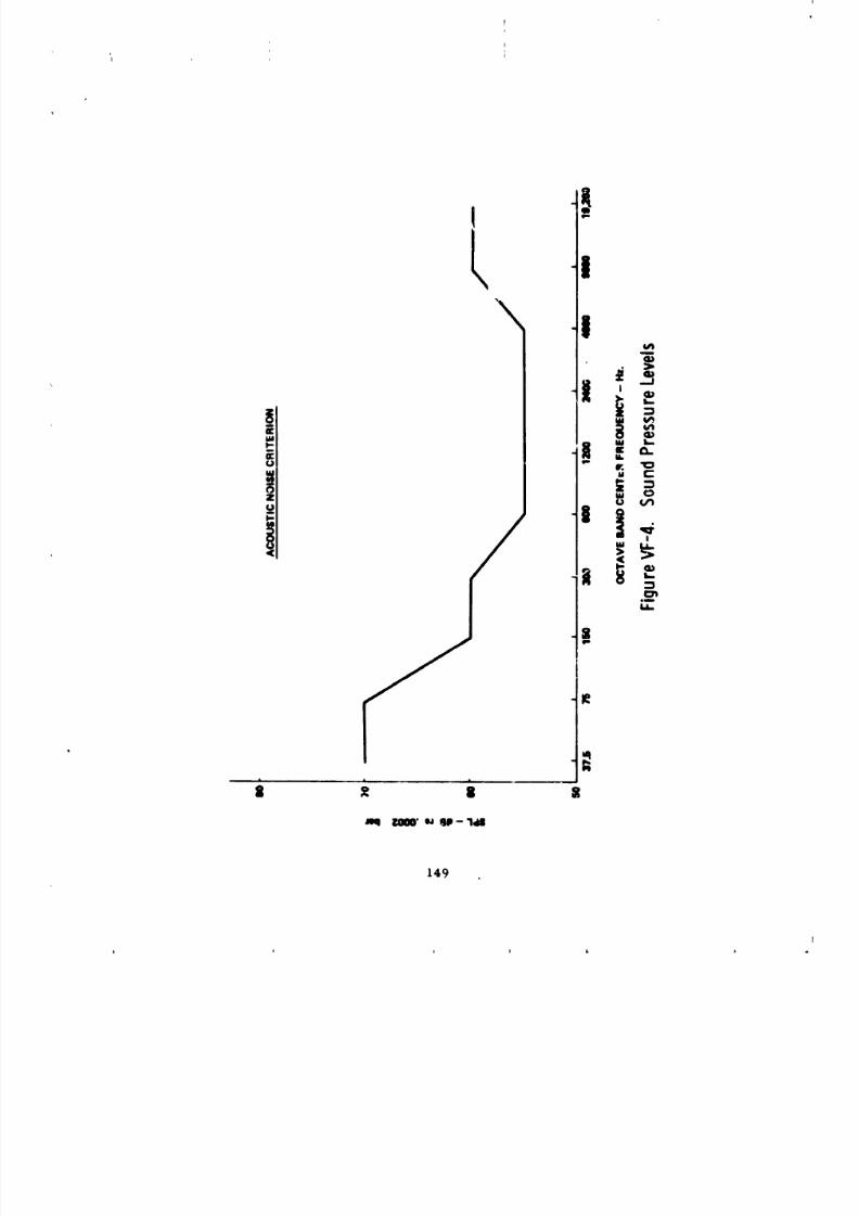
8/8/2019 MSFC Skylab Structures and Mechanical Systems Mission Evaluation
http://slidepdf.com/reader/full/msfc-skylab-structures-and-mechanical-systems-mission-evaluation 166/348
mq m' e__jp- 18
149
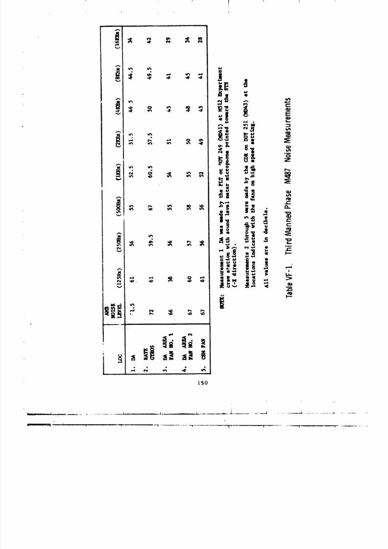
8/8/2019 MSFC Skylab Structures and Mechanical Systems Mission Evaluation
http://slidepdf.com/reader/full/msfc-skylab-structures-and-mechanical-systems-mission-evaluation 167/348
t
8/8/2019 MSFC Skylab Structures and Mechanical Systems Mission Evaluation
http://slidepdf.com/reader/full/msfc-skylab-structures-and-mechanical-systems-mission-evaluation 168/348
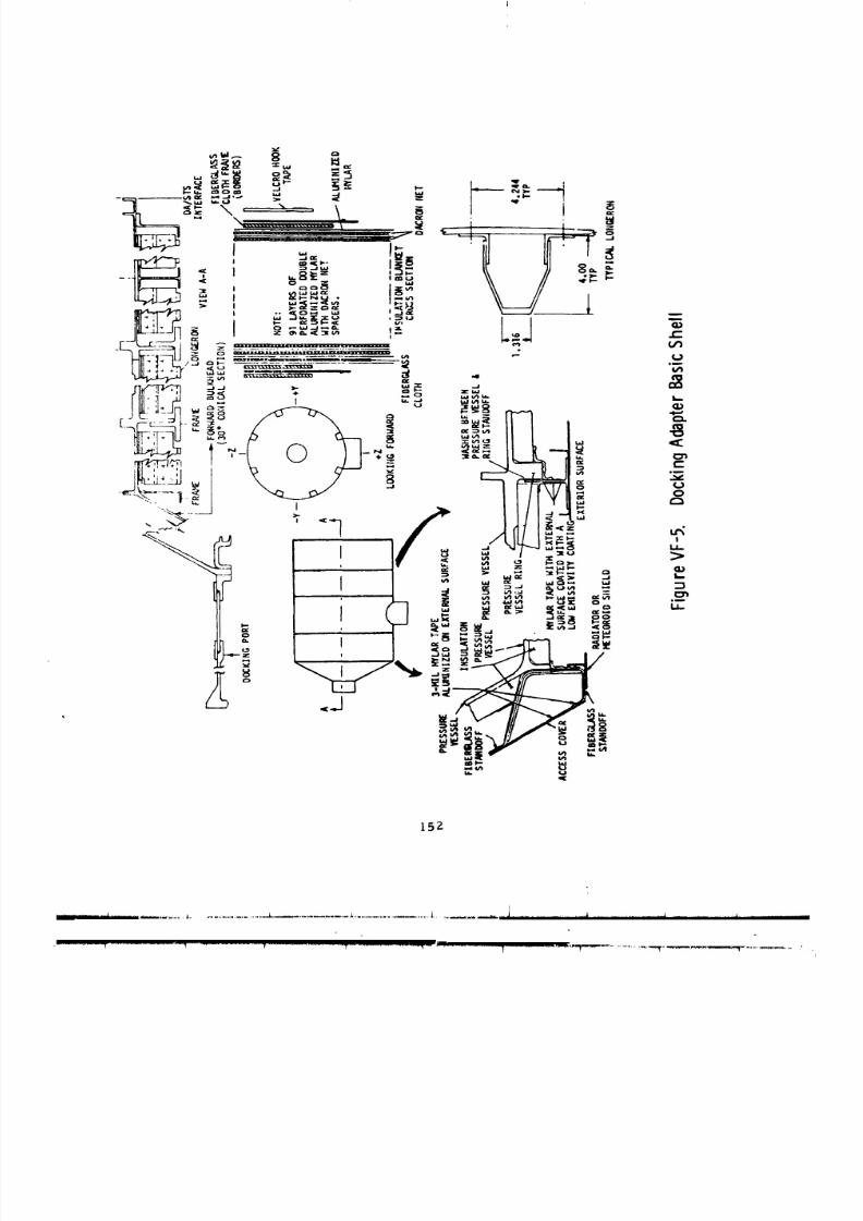
8/8/2019 MSFC Skylab Structures and Mechanical Systems Mission Evaluation
http://slidepdf.com/reader/full/msfc-skylab-structures-and-mechanical-systems-mission-evaluation 169/348
15Z
_ ............... ._ ......... i . .. .. .. .. .. .. .. .. .. .. .. .. .. .. . , ,_,,.--_,,,',,*_,--_-',m,,,-m,i .........................i¢-- ........ i..... I_ .... _- --,] ............... _ lnllgnllf........... J ........... nnIIiI- • ..........
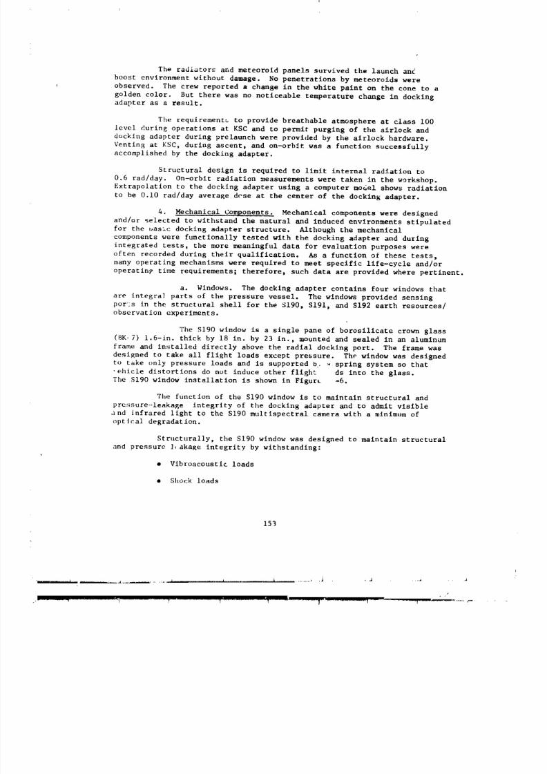
8/8/2019 MSFC Skylab Structures and Mechanical Systems Mission Evaluation
http://slidepdf.com/reader/full/msfc-skylab-structures-and-mechanical-systems-mission-evaluation 170/348
8/8/2019 MSFC Skylab Structures and Mechanical Systems Mission Evaluation
http://slidepdf.com/reader/full/msfc-skylab-structures-and-mechanical-systems-mission-evaluation 171/348
S190 WINDOW
F,gure VF6 S190 Window Installation
IbEPRODUOmILl_ zO_i'_ _,_
J
8/8/2019 MSFC Skylab Structures and Mechanical Systems Mission Evaluation
http://slidepdf.com/reader/full/msfc-skylab-structures-and-mechanical-systems-mission-evaluation 172/348
• Pressure (6.2 psig limit pressure)
• Temperature extremes (-40 to 160 °F)
• Van Allen Belt radiation
• Micron_teoroid impact
• Accidental impacts from the crew
The window was designed to the following structural factor of safety
requirements:
Proof pressure = 2.00 times limit pressure
Burst pressure = 3.00 times limit pressure
As a sensing port for the £190 multispectral camera, the window was
designed to comply with the following specific requirements:
• Wavefront distortion
• TransmJ_sibility
• Refleatance
• Glare
• Contamination control
• Moisture condensation prevention
• Crew protection from ultraviolet radiation.
The S190 window was subjected to an extensive development _,id
qualification program to prove its ability to meet those requirements.
Tests of the window included development, qualification, acceptance
arid specimen testing:
• Successful deuelopment, qualification, and acceptance testing of the
prototype and flight window inc]uded flaw-screening, vibration,
shock, proof pressure, sea] leakage, impact and thermal stress.
Optical testlnR included wavefront distortion, transmissibility,
reflectance, and glare.
• Full-size specimens--A full-s_ze window pane was successful.tested to 124 psid (safety factor of 20). A second specimen
successfully withstood I_ psid after being scored with a glass
155

8/8/2019 MSFC Skylab Structures and Mechanical Systems Mission Evaluation
http://slidepdf.com/reader/full/msfc-skylab-structures-and-mechanical-systems-mission-evaluation 173/348
cutter to make a shallow 18 in. long scratch. After a 0.35-in.
deep flaw I-in. long was made in the center of the other (unscratched)
surface, using a thermal stress cycling technique, the specimen
broke at 24 psid. Both tests were conducted with the flawed
surfaces in tension.
• Sample specimens--100 6-in. diameter specimens of BK-7
glass were tested to determine the degradation caused by coatings,
buss bars, humidity, temperature extremes, Van Allen Belt radiation,
and 8-month vacuum exposure. The specimens were arranged in
groups of i0 for statistical evaluation of individual environments.
No degradation in _lass strength was caused by any of the environments.
• Bar specimens--25 bars of BK-7 glass were tested to obtain
data about critical stress versus crack size and crack growth rate
for long-term loading effects.
• Block specimens--12 pieces of BK-7 glass (l.6-1n. thick)
did not static discharge or crack after being subjected to
varying amounts of electron radiation, up to an amount cor-
responding to more than 200 yrs in orbit.
Each window pane was flaw-screened by pressure testing to 30 psid.
Window assemblies were proof pressure tested to 14.7 psid.
Three smaller windows in the docking adapter were used by the S191
and S192 experiments. The S191 window was 4 in. in diameter by 0.48-in.
thick. Its function was to act as a viewing port for crewmen
when pointing the viewfinder t acker system at the selected target.
The two S192 wlndows were 3 in. in diameter by 0.25-in. thick.
One was made of germanium and the other of fused silica (Infrasil).These windows transmitted selected wavelengths of radiation to
the S192 experiment internal scanner.
An extensive te:_t program _as conducted on the S191 and S192
windows and window material. These tests include development, qualification,
acceptance, _nd specimen testing:
• Successful development qu111fication and acceptance testing of
prototype and fltEht windows included flaw-screenlng, vibration,
shock, proof pressure, and seal leakage. Optical testing included
transmittan¢:e, reflectance, wavefront distortion, and surface
quality.
• Full-size specimens (25 germanium test specimens and 25 of Infrasil)
were tested to determine whether degradation was caused by coatings,
humidity, temperature extremes, Van Allen Belt radiation, and 8-
month vacuum exp-_ure. None of the environments caused a degradation
in _t rength.
156
8/8/2019 MSFC Skylab Structures and Mechanical Systems Mission Evaluation
http://slidepdf.com/reader/full/msfc-skylab-structures-and-mechanical-systems-mission-evaluation 174/348
I I
i
• Bar specimens--Two bars of germanium and two of Infrasil were
tested to obtain data about fracture toughness and cTack growth
rates under sustained ]oad_. Similar data were obteined for BK-7
glass in connection with S190 window testing.
Each window was f]ow-screened by pressure testing to 30 psid for
the S192 windows and to 45 psid for the S191 windows.
Careful monitoring of window temperatures and atmosphere dewpoint
was carried on throughout the mission, bacause of the sensitivity of the
performance of the window to condensation. Figure VF-7, showing dewpoints
and window temperatures for the first manned phase, shows that condensation
conditions did not occur. This conclusion is supported by crew obse. vations.
All four windows apparently operated normally throughout the mission.
No problem was reported by any of the three crews. No distortion of data
due to the windows was observed.
b. Covers. External and internal protective covers for the
S[90 window are provided (Figure VF-8) to protect the surfaces of the window
from micrometeoroid impacts, contamination, and internal impacts. The
external window cover is mechanically operated from within the docking
adapter. It was opened for all earth resources/observation passes, hand-held
photography, and viewing. Insulation is installed on the external window
cover to minimize heat loss. The safety shield (internal cover) is transparent
and removable from the inside. It was designed to provide sealing
redundancy for the S190 window and to withstand pressure, impact, and
vibroacoustic loads. The shield was removed only for earth resources/
observation operations.
The externa] cover is a curved fiber glass honeycomb panel 1-in.
thick by approximately 20 by 31 in. It contains metal fittings,
integral]y bonded to the panel, for hinge attachment and latch engagement.
Multilayer insulation is installed in a fiber glass pan that is attached
to the internal surface of the cover. The cover (including the pan)
is painted black for thermal control and to minimize reflected light on
the window. A resilient foam seal around the cover edge closes the
gap between the cover and the meteoroid shield to prevent dust and
other contaminants from reaching the window. The honeycomb panel has
scw_ral wmt holes to relieve internal pressure during beost.
157
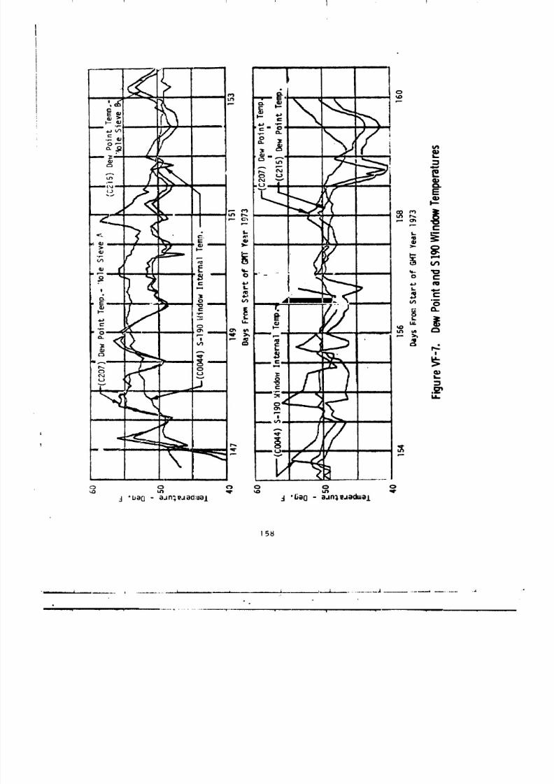
8/8/2019 MSFC Skylab Structures and Mechanical Systems Mission Evaluation
http://slidepdf.com/reader/full/msfc-skylab-structures-and-mechanical-systems-mission-evaluation 175/348
1 l
158
_ ....... i ......................... i ......................... _. _ ........... i , ,,,,, , ,-._-._[ ....................... _,,,A .......... _ ................ ,,i,
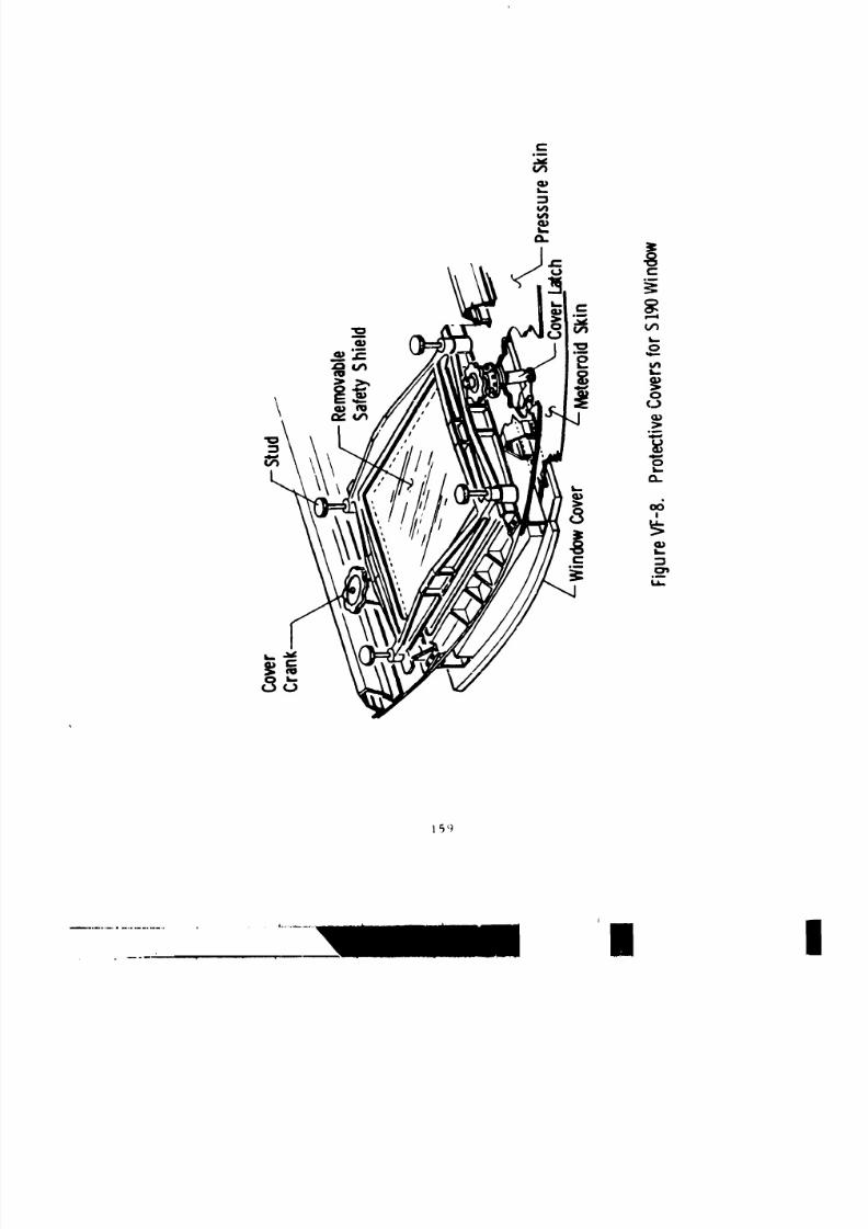
8/8/2019 MSFC Skylab Structures and Mechanical Systems Mission Evaluation
http://slidepdf.com/reader/full/msfc-skylab-structures-and-mechanical-systems-mission-evaluation 176/348
8/8/2019 MSFC Skylab Structures and Mechanical Systems Mission Evaluation
http://slidepdf.com/reader/full/msfc-skylab-structures-and-mechanical-systems-mission-evaluation 177/348
The cover was designed to meet the following criteria:
• Provide meteorold protection fo_ the window equivalent to
the adaJacent structure.
• Mln_mize heat loss through the window.
• Provide contamination protection for the window.
• Provide venting for the cavity between the cover and window to
a_con_nodate pressure changes during transportation, purgipg,
and the ascent port_on of the flight.
• Withstand all imposed loads.
• Meet outgassing criteria.
Another protection the cover provided for the window was against the
_pace radiation environment.
Two mechanical devices, an actuator and a latch, are installed
on opposite sides of the SIgU window to hold the external cover in
place during boost and storage periods, and to enable the crew to open
the cover when the window is to be used. The latch is operated
by turning the latch handle counterclockwise approximately seven tu:ns.
'i'llisperation moves an external latching arm outboard, freeing the edge
of the cover so it can be opened. The cover is then opened
by tum_ing the actuator handle clockwise. This actuator handle is
connected to the cover hinge through a gear set that moves t_ cover
through free-half the angle of the handle. Rotating the hand_ 270 °
move_ the cover to an angle of 135 ° from the window, which removes
the cover from the field of view of the Si90 camera. The actuatorhandle [_is , cam that operates a warning-light mlcroswitch to indicate
to the crm_ tha_ the external cover is closed. The actuator and latch
mechanlsms were designed for ease of operation and to provldecomfortable
tou_h temperatures for the crew. They were also required to withstand
all laum h ;rod operational environments without functional degradation.
A mech;,ntca! design was specified to assure reliability. Maximum design
|oad_ w_,re I_} in.-ib torque on the latch and actuator knobs, Actual
op_,rati,,_ torque_ were 13 [n.-ib or le:_s as measured in preflight
ch,,_ko,t at KE(:. Specifications required window covers to be designed
f_r a _lin_,,um of 300 operating cycles. The slg0 window cover mechanism
wa_ qualification te_ted for 500 cycles and operaLed in orbit for 100 cycles
withont any problems.
'l'h_. saf_.ty shield i_ a removable Internal cover for the S190 window.
It is p,_sitiont.d a_ainst thu Inside of the window frame and
Ib0
8/8/2019 MSFC Skylab Structures and Mechanical Systems Mission Evaluation
http://slidepdf.com/reader/full/msfc-skylab-structures-and-mechanical-systems-mission-evaluation 178/348
ban(' fastened there by a crewman whenever the S190 experiment was rotated
into its stowage position back away from the window. The
, saf,_-tyshield consists of a hlgh-strength glass panel, (Coming Chemcor
0315), 0.290-In. thick, mounted and sealed in an aJumlnum freme. The frame
includes an O-rlng on its mounting surface to provide sealing redundancy
iv; the St90 window. The function of the safety shield is to _'otect
the S190 window from possible damage resulting from the impact of
loose objects within the docking adapter and to act _s a redund'q_t pressure
seal in case the S190 window had failed. The safety _hield pressure
seal was launched in its stowage position on the aft end of film vault #4.
Tests were conducted to verify the capability of the window
cover mechanisms to withstand the design environments and operating
conditions for the duration of the mission. The tests included measure-
ments of operating torque and leak rate before and after exposure to
vibration and acoustic excitation. A 30-day vacuum test demonstrated
that the mechanism would function properly without excessive
leakage under orbital conditions. A development external cover
was included in the mechanism tests of vibration, acoustics, and
operating cycles. Although the sole purpose of the cover ",inthese tests
was as a mass simulator, the cover successfully withstood all test
environments.
Acceptance and qualification testing of the safety shield included
impact resistance, vibration, proof pressure, and leakage of both the
glass seal and O-ring redundant seal.
Acceptance tests on the safety _hleld glass panels included
both structural and optical tests. Structural integrity was demonstrated
by pressure testing and thermal-shock testing to 540 ¢F to screen the panels
for hidden flaws. Optical clarity vas assured by testing for high
transmittance and absence of distortion.
The external window cover and the safety shield successfully performed
a]l required functions during the Skylab mission. No adverse comments
were reported by any of the three crews.
_. L_,cking ports. The docking adapter has two docking
ports, rh¢_ axial docking port, which is the primary docking port,
i_, located at the forward end of the docking adapter and centered
about tlle X axis. The radial (secondary) docking port is located
[03 in. forward of the docking adapter/alrlock interface on the
+Z axis.
Both the axial and the radial docking ports have st;mdard
Apollo dro_,jtes and docking interfaces to permit docking of the co,mland
_)(l,:le. The axial p,,rt is equippod to transfer electrical power,
16t
8/8/2019 MSFC Skylab Structures and Mechanical Systems Mission Evaluation
http://slidepdf.com/reader/full/msfc-skylab-structures-and-mechanical-systems-mission-evaluation 179/348
c_r_-mnications, and conditioned air between the docking adapter and
the command and service module following docking.
Decking aids f_r visual ot'lentation and alignment are provided to
facilitate docking. The docking aids were designed to permit
docking operations to be accomplished independent of flight control
data. The docking targets are of the Lunar Module type. The
,:xternal surface of the forward cone of the docking adapter is
provided with a white circular stripe at its outer diameter to aid
doc_ing. Four exterior lights are installed for visual orientation.
No tests wer__ required to verify structural integrity of the
Jocking hardware, since the existing Apollo docking eystem was used.
A docking test was conducted at KSC using the flight docking adapter
and the command and service module used for the first manned phase
to verify the docking system. Objectives of this test were to verify
docking capability at the axial port, to check the docking interface
leak rate, to verify alignment of the axial docking target, to
verify fit of the air interchange duct and Lhe electrical bonding
between the cr,_land and service mod.ule and the docking adapter.
All t,-_tswere successful. The measured leak rate of the docking
interface was 0.009 ib/day, compared with an allowable rate of 3.14 ib/ddy.
A soft docking was done on the first manned phase. At this time, the
command and service module probe captured the docking adapter drogue but
the probe retraction mechanism was not activated since a standup extravehic-
ular activity was planned. The probe was then released and the standup extra-
vehicular activity maneuver was performed. Following this, hard docking
w._ attempted. Several unsuccessful attempts to engage the drogue and probe
were made. The command and service module probe was then corrected
by the crew during extravehicular activity to permit retraction with-
out capture latch engagement. Docking was achieved by applying reaction
_ontrol system tt_rustuntil the docking latches engaged. No data are
,vailable m_ actual docking rates, but successful docking was demon-
qtrated by the automatic engagement of all 12 latches and the absence
el I,:ak._n the docking tunnel. The crew reported that alignment ac-
curacy was 1.5°, as measured by an Inde_ scale that was permanently in-
_,t,_lled in the dockiug port.
[he terra,nd and service module successfully docked to the docking
a,l,q_t_.ru the initial attempt by tne second manned crew. Docking conditions
'.,_.r,,._tninal.The docking adapter internal pressure was 5 psia at the time
,,! docking. After entry into the docking adapter, the crew noticed that
,,Jt,tttaudnd servic_ module docking latches #l and #I0 were loose on
• tht.docking adapter docking ring. The remaining latches were adequate to
t._, .It expected lo.ds and to prevent leakage in the docking tunnel; there-
tt_rL.,,, corrective action was necessary. Alignment accuracy of docking was
,. ,", as m, asured by the index scale in the docking port.
162
J |
8/8/2019 MSFC Skylab Structures and Mechanical Systems Mission Evaluation
http://slidepdf.com/reader/full/msfc-skylab-structures-and-mechanical-systems-mission-evaluation 180/348
Three attempts wore required to achieve a hard dock by the third
_a_med cr(,w. All 12 latches engagL4 automatically, alignment accuracy
wa._ 0.7 °F, as measured by the index scale in the docking port.,
(I. Hatches. Tile docking adapter .lad two circular, inward-v
(q_uning h,_tche:_, one at each docking port. The hatches are 32 in. in
(li:,mett. r :rod t.2-in, thick. Each hatch is held in the closed position by
_ix ,)vert'enter latc-h(,a. The latches are controlled by ]_nkages attached
to a central sh.lft. Handles ,ira nttached to the st,aft on both sides of the
hatch, thereby allowing opening and closing from either side. The handles
:_r,. restrained in a launch lock which is locked from the outside only,
but could be unlocked from either side. The edge of the hatch i., a lip
that d,'I,r_'s_ed ._ silicone rubber seal in the docking adapter shell decking
i.,,rt ring it, achieve o pressur. _ tight closure. The amount of seJ1 indentation
is limited by six mechanical stops to prevent overstresstng of the seal.
Tim hatch i_ owa_ in Figure VF-9.
Requirements of the hatch are: (1) provide a press.re tightclosure (2) be operated easily by the crew, and (3) wltl,stand all handling
and operation envlronments without functlonal degradation.
The hatch handle temperatt, res are required to be maintained
betwee: IO5 and 35 °F during docking and all manned operations. Min'-'mum
Force required to activate the hatch handle_ is 2 lb. The maximum force
:'_,¢uired to actuate tile latching handle and p,=essure equalization valve
in not to exceed 25 lb. The maximum force required to o?en the hatch is
nc>t to exce_d 45 lb. The stowage provisions for the hatch in the open
p,_ition were designed so that a force of 5 to 25 ib on a hatch would be_utfici¢.nt to latch :_pd unlatch the hatch. The hatches are also
r_qu/r_,d to be removnble and interchangeable.
Compont.nt qualification tests of tile hatch were used to
,.h.r,m._trat,. the adt.quacy of the dent}on for launch and orbita! conditions.
qu.,lificati,m t(,sts verlfl4.d the final hatch design for pressure, vibration,
l_yr(_t_,chni( sho_k and ultlmatu handle forces. Maximum pressure in tnese
t,...t_ wt. ce 12.4 psig. The ultimate handle force tested was 210 lb.
The f light hatches were l ested for leakage before instal-
I._ti,_u :,nd f_r handi_, operating Sorres after Installation. Haximum
l_.,,k;_g_, reentered on .t flight hatch was 0.046 lb/day, compared "_itb an al
I,,¢.tbl,. rjt_. of 0.52 lb/day. Handle operating forces were 6 lb for opening,
, l,,,,in_;, :rod unstowing the hatch, well within the 5 to 25 lb allowed.
163

8/8/2019 MSFC Skylab Structures and Mechanical Systems Mission Evaluation
http://slidepdf.com/reader/full/msfc-skylab-structures-and-mechanical-systems-mission-evaluation 181/348
164
1 i ] I
8/8/2019 MSFC Skylab Structures and Mechanical Systems Mission Evaluation
http://slidepdf.com/reader/full/msfc-skylab-structures-and-mechanical-systems-mission-evaluation 182/348
the hatch seal was tested separately to ensure integrity under
long llfe thermal vacuum conditions. Tests were conducted on sections of
hatch seals to determine the ability of the seal to withstand long periods
of compression under operational conditions and to determine whether sticking
of the seal to the hatch could become a problem. Test specimens were4-in. long cut from a production seal. The specimens were compressed in
a fixture resembling a seal retaining ring, and placed in a vacuum
chamber with controlled temperature. Periodically, specimens were removed
from the chamber, pulled to measure sticking force, and examined for
damage. The test program was successfully concluded after 8-months
exposure of the final seal configuration with no damage and with acceptably
_mall sticking forces. Another test of a full-slze seal was conducted
to measure leakage degradation over 8 months of' compression. This
test, which was at room ambient conditions, showed negligible leakage
of the seal after the full mission time.
The axial hatch was opened and closed three times during the Skylab
mission. No problems with the hatch were reported by the crew. The
radial hatch was not used.
e. Pressure equalization system. The docking adapter hatch
p_essure equalization subsystem provides means of equalizing the atmospheric
pressure between the command and service module and the docking adapter
after docking and prior to workshop entry. Each docking port hatch
is equipped with a visual differential pressure gage and a manually-
operated equalization valve. Equalization of pressure across the hatch
is achieved by opening the valve.
The differential pressure gage assembly consists of t_o gages
mounted back-to-back in both pressure hatches. The assembly allows
delta pressure monitoring from either side of the hatch. The basic
gagu was developed and used on the Apo]lo program and requalifled for
Skylab use. The gage had a range of _i.0 Fsi and a required accuracy
of 0.i psi.
The pressure equalization valve provides a flow path for
eq,,allzlng the atmospheric pressure prior to astronaut entry into the
docking adapter. The valve is opereted by depressing a button in the
valve handle and rotating the handle. The valve is capable of being
operated from either side of the hatch. A cap provides redundant sealing
capability. This valve _s also used on the alrlock.
Qualification tests of the differential pressure gage assembly
ctm;isted of CCOH, temperature, llfe cycle, vibration, shock, vacuum,
and pressure. A performance test, consisting of proof pressure, accuracy
4nd leak check, was performed after each environmental test.
Each gage assembly received an acceptance test to demonstrate
suJlal,[e qua|_ty, correct assembly, and required performance. The gages
were. v{_,._a]], 4nl dimensionally inspected, checked for pressure indicating
acc, racy, _uhmitted Lo a proof pressure integrity test, and subjected
to _ ]_al_ test. All tests were completed satisfactorily.
165
I j J I
8/8/2019 MSFC Skylab Structures and Mechanical Systems Mission Evaluation
http://slidepdf.com/reader/full/msfc-skylab-structures-and-mechanical-systems-mission-evaluation 183/348
Qualification tests on the pressure equalization valve were success-
fully performed according to requirements set forth for the aitlock.
These test:_ consisted of the following environmental tests: High and
iow temperature, oxygen atmosphere, vacuum, vibration, shock,
cycle test, limit load, proof pre3sure, ultimate load, burst pressure,
salt, fog, and humidity. A performance test was conducted after
each environmental test.
Each valve received an acceptance test to demonstrate suitable
quality, correct assembly, and required performance. Each valve
was visually and dimensionally inspected, checked for flow rate
capacity, subjected to proof pressure, tested for internal and
external leakage, and the detent spool was examined for centering
ac_justment. All valves tested met the acceptability requirements.
Design operating life of the equalization valve was 30 cycles
for orbital usqge. Only five cycles were actually accumulated for the
three manned phases.
No problems were encountered with the differential pressure gage
or the pressure equalization valve during the Skylab mission.
5. _lounting Provisions and Installations. The docking adapter
provides structural support for various experiments and crew equipment.
These include the M512 materials processing facility, the S009
experiment, the radio noise bu£st monitor, speaker intercoms, fire
sensor_ fire extinguisher, fans, and various items of crew and
experiment equipment. All items are permanently attacbed to longerons
or to intercost_is suspended between longerons.
These support fittings and structure were all designed with a factor of
safety of 3.0, and were consequently not tested. All these items per-
formed without failure throughout the mission.
Additional equipment and experiments instslled in the docking
adapter are described in the following paragraphs.
e. Telescope mount control and display panel. This panel
is mount_d in bay 4-A of the docking adapter. It is supported on
_hock mounts from two beams that are located at vehicle stations 3445
and 35i0 The shock mounts protect the panel from launch vibration
excitation and reduce the environment for components in the panel
to acceptable levels.
Structural supnorts for the panel were designed using a
factor o[ safety of 3.0 to eliminate the requirement for testing.
166
J i _ J i I
8/8/2019 MSFC Skylab Structures and Mechanical Systems Mission Evaluation
http://slidepdf.com/reader/full/msfc-skylab-structures-and-mechanical-systems-mission-evaluation 184/348
b. Earth cesources/observations hardware. Various types of
structure are used to mount earth resources/observation equipment in the
docking adapter. Base plates for S191 and S192 are installed in cutouts
in t_e shell and became part of the primary structure. The S190 experi-
ment is mounted on four fittings that attach to hard points on the @ockingad=pter structure. Various electronic equipment is mounted on three
trusses which are attached at frame-longeron intersections. The S194
antenna and electronics package are mounted externally on the L-band truss.
All earth resources/observation support structure was designed
using a factor of safety of 3.0, and no testing was performed to qualify
these items. The S191 and $192 base plates were installed in the
static test article during performance of all structural tests. These
plates were also installed in the docking adapter flight article
befe. e proof pressure and leakage tests of the module were conducted.
The earth resources/observation support structure supported all
equipment during boost and throughout the mission without failure.
c. L-band truss. This truss consists of aluminum tubular
melabers welded and bolted together. Additional frames, brackets,
etc., are attached to the truss to provide interfaces for the antennas,
L-band electronics, proton spectrometer, and the inverter lighting control
assembly.
All truss members are wrapped with aluminized mylar =ape :o help
,_:aintain thermal balance.
The truss is configured to iDterface with the docking adapter
at three points: One point is an existing liftlng fitting at the cone-
barrel joint located to one side of the Z axis. A second point is on
the opposite side of the Z axis at the cone/barrel joint. The third
attach point is to an adjustable link that attached to the axial docking
pozt-cone intersection.
A factor of safety of 3.0 was used in designing the truss, and no
testing was required.
The L-band truss supported all its equipment without failure.
167
', j
8/8/2019 MSFC Skylab Structures and Mechanical Systems Mission Evaluation
http://slidepdf.com/reader/full/msfc-skylab-structures-and-mechanical-systems-mission-evaluation 185/348
d. Foot restraints. Two foot restraint platforms are provided
in the docking adapter for astronaut support when operating experiments.
The platforms were fabricated from standard astrogrid to interface with
the astronauts shoes. The telescope mount control and display platform was
designed to be used oy two crewmen and is approximately 17 by 49 in.
It is adjustable, with three using positions and a stowage position. The
using positions provide a vertlcal adjustment of 12 in. This platform
is used to support the telescope mount console body restraint operatorts
chair when in use. The earth resources/observation/M512 platform was
designed for use by one crewman working either at the earth observation
panel or the M512 experiment. Two mounting locations are provided and
two platform orientations are possible. A third location is used for
platfo_ stowage during launch.
These foot restraints were designed for a specified ultimate
concentrated load of 140 lb. Launch conditions were also critical
for some components. When requirements were identified to use the foot
restraints for launch stowage of the extravehicular activity batch
wi_dow cover, the S183 kick plate, and the scientific airlock wxndows,
it was necessary to reduce the design environment in order to retain
an adequate factor of safety. Vibroacoustic datd were used to define
new vibration load factors, and the required factor of safety of 3.0
was demonstrated by analysis.
Both foot restraints successfully withstood the launch environment
and were used without problems throughout the Skylab nLission. The telescope
mount foot restraint was used to support the console body restraint
_,nly sparingly during the second and third manned phases, The earth
r_sources/observation/M512 foot restraint was moved from its stowage
location and was used in both the EREP and M512 positions.
e. Coutrol and display console body restraint device.
The restraint assembly was designed for use by the crewmen during
ooe,ation of the control and display console. The design consisted of a
base plate that attached to the floor grid pattern (astrogrid) at the base
of the console. This attachment consists of two cleats that fit at the
g_iJ corners and two clamps that pin the base plate to the grid. A
seat with variable height adjustments is installed on the base plate
with one quick release pin. The position of the back rest is made
variable by rotating it on hinge pins and then securing the desired
position with quick release pins. A lap seat belt is also provided
(Figure VF-IO).
The assembly was designed for a maximum working load of
1 50 Ib iu the fore ard aft direction normal to the face of the control and
display console and a maximum working load of 120 ib in the side-to-
side: direction p_rallel to the face of the console.
168
t J i J
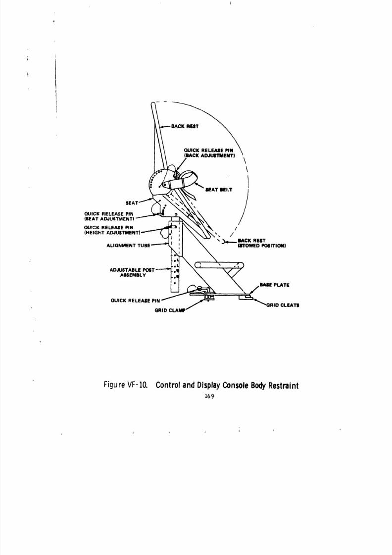
8/8/2019 MSFC Skylab Structures and Mechanical Systems Mission Evaluation
http://slidepdf.com/reader/full/msfc-skylab-structures-and-mechanical-systems-mission-evaluation 186/348
(BACK ADJUSTMENT)
,/ \\
SEAT BELT
/l ,_ _
QUICK RELEASE PIN o
(SEAT ADJUSTMENT) "--
QU!:K RELEASE PiN _ _ /
(HEIGHT ADJUSTMENT) __j /"__ I IACK REST
ALIGNMENT TUBE ''''_ (_rOWED PO61TION)
-el.o2 _ , •
ADJUSTABLE POST-"--'* .,|
AUEMBLY .,11
* BASE PLATE
QUICK RELEASE PIN GRID CLEATS
GRID CLAMP
FigureVF-IO. ControlandDisplayConsoleBodyRestraint169
'L |
t J lJ
8/8/2019 MSFC Skylab Structures and Mechanical Systems Mission Evaluation
http://slidepdf.com/reader/full/msfc-skylab-structures-and-mechanical-systems-mission-evaluation 187/348
The assembly was stowed by installing it on the floor grid of
the workshop with the seat in its lowest position and back rest
folded over the seat. This provided the lowest center of
gravity for the package and thus reduced the vibration ana launch loads.
A qualification test item was vibration tested at MSFC to l_unch
conditions, with the restraint assembly in the secured position, simulating
the launch configuration. One of the welds between the back rest panel
and the back frame cracked at a fillet weld during the first vibration
test. The design was modified to add a reinforcement angle at this weld
joint and the vibration test was repeated with no failures. Following the
vibration test, the assembly was adjusted to all the possible positions
with no problems and the assembly was considered qualified.
The body restraint was used by some crew members and not by others
because they felt they would be more restricted at the control and display
console if they used it. The use/non-use option was provided, through design,by making the restraint collapsible into a compact configuration when not
in use. When used, the seat and back adjustment was optimized for the
crew members so readjustment was unnecessary during each manned phase.
6. Stowage. The docking adapter providea stowage for various ex-
periment and crew items used in the Skylab mission. Film vaults and
stowage containers were used to stow many items. Some larger equipment,
such as film cassette trees, fire extinguisher D and secondary oxygen
pack, were stowed on brackets in the docking adapter. All such brackets
were designed using a factor of safety of 3.0 to eliminate the require-
ment for testing.
a. Film vaults. Four film vaults are installed im the docking
adapte to provide stowage for the telescope mount cameras and film,
and miscellaneous items for the Skylab mission. The film vaults are of
various sizes and wall thickness to meet physical and radiation re,luire-
H_ts d_fined in their re_pective interface control documents.
The film vaults are located and supported at locations best
suited for crew operation and to sus n launch loads. The vaults were
fabricated from _06_-T6 aluminum. D_ zs attach to the Dasic box with
a continuous piano hinge and lock in place for launch loads with expando
pins. l)u_ing activation by the first manned crew, the expando pins were
re;_kaced with pins. The doors are equipped with a fr_ction device to
control inertka forces on the door during crew operations in zero g.
170
1 I _ J I
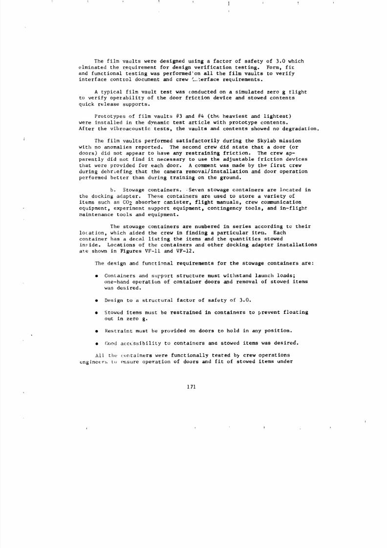
8/8/2019 MSFC Skylab Structures and Mechanical Systems Mission Evaluation
http://slidepdf.com/reader/full/msfc-skylab-structures-and-mechanical-systems-mission-evaluation 188/348
The film vaolts were designed using a factor of safety of 3.0 which
elminated the requirement for design verification testing. Form, flu
and functional testing was performed'on all the film vaults to verify
interface control document and crew i._erface requirements.
A typical film vault test was conducted on a simulated zero g _llght
to verify operability of the door friction device and stowed contents
quick release supports.
Prototypes of film vaults #3 and #4 (th_ heaviest and lightest)
were installed in the dynamic test article with prototype contents.
After the vibroacoustic tests, the vaults and contents showed no degradation.
The film vaults performed satisfactorily during the Skylab mission
with no anomalies reported. The second crew did state that a door (or
doors) did not appear to have any restraining friction. The crew ap-
parently did not find it necessary to use the adjustable friction devices
that were provided for each door. A comment was made by the first crew
during debriefing that the camera removal/installation and door operation
performed better than during training on the ground.
b. Stowage containers. Se_en stowage containers are located in
the docking adapter. These containers are used to store a variety of
items such as CO 2 absorber canister, flight manuals, crew communication
equipment, experiment support equipment, contingency tools, and in-flight
maintenance tools and equipment.
The stowage containers are numbered in series according tQ their
location, which aided the crew in finding a particular item. Each
container has a decal listing the items and the quantities stowed
inside. Locations of the containers and other docking adapter installationsa_e shown in Figures VF-II and VF-12.
The design and functional requirements for the stowage containers are:
• Containers and support structure must withstand launch loads;
one-hand operation of contalx_er doors and removal of stowed items
was desired.
• Design to a structural factor of safety of 3.0.
• Stowed items must be restrained in containers to prevent floating
out in zero g.
• Restraint must be provided on doors to hold in any position.
• Cood accessibility to containers ana stowed items was desireH.
All the containers were functionally tested by crew operations
engineer_ tu (_sure operation of doors and fit of stowed items under
171
j j ' | 1
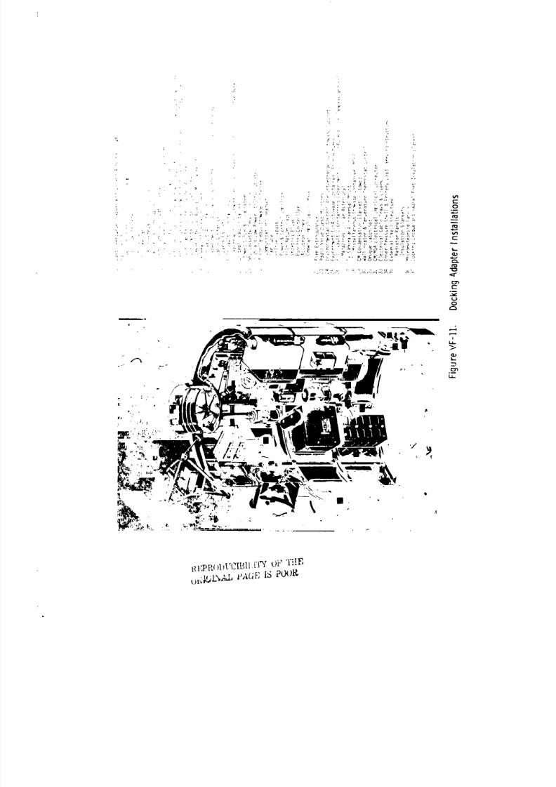
8/8/2019 MSFC Skylab Structures and Mechanical Systems Mission Evaluation
http://slidepdf.com/reader/full/msfc-skylab-structures-and-mechanical-systems-mission-evaluation 189/348
tl I,;PI{_}I_I'CIBll, tTY Oi" 'I'}!B
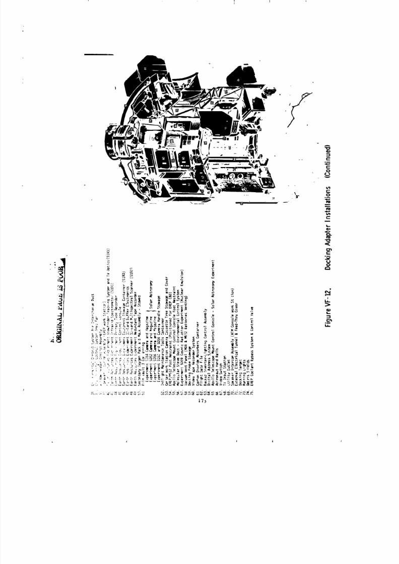
8/8/2019 MSFC Skylab Structures and Mechanical Systems Mission Evaluation
http://slidepdf.com/reader/full/msfc-skylab-structures-and-mechanical-systems-mission-evaluation 190/348
I
8/8/2019 MSFC Skylab Structures and Mechanical Systems Mission Evaluation
http://slidepdf.com/reader/full/msfc-skylab-structures-and-mechanical-systems-mission-evaluation 191/348
I
si ulated on-orbit operatiors. Removal and installation forces, restraint
capabilities, and door operation were evaluated during several crew
compartment fit and functlon reviews and altitude-chamber exercises.
During altitude chamber tests, it was discovered that Mos_te foam used
for cushioning in the containers experienced growth when docking adapter
internal pressure was reduced. This altered the dimension of stowage
cavities. The problem was corrected by increasing the cavity size
in the Moslte and revising the restraint system. No structural verifica+ion
testin_ was required because of the large factor of safety ue_i for the design.
The stowage container configurations, locations in the docking
adapter, door arrangement, and methods of supporting and stowing the items
in the containers were satisfactory for all applicable mission operations.
The hardware performed during the mission without any problems.
7. Mechanical Systems. The docking adapter mechanical systems
consist of the ventilation system, the telescope _unt/earth resources/
observation cooi&_t system, the docking adapter ventilation system,
and MSI2/M479 experiment vent system.
a. Ventilation system. The ventilation system design requirements
consist of the following:
• Flow rate per cabin atmosphere hard duct (3 ducts)--55.7 cfm.
• Allowable pressure drop for cabin atmosphere ducts--O.O172 in.
of water at 55.7 cfm.
• Flow rate for u, lecular sieve duct (two compressors)--62
+ i0 cfm.
• Allowable pressure drop for molecular sieve duct--O.035 in.
of water at 62 cfm.
• Flow rate through the atmcsphere interchange duct i00 to 170scfm at 70 °F.
• Interface pressure--llne pressure loss in command module
portion of the atmosphere interchange duct not to exceed
0.07 inche_ of water at 150 scfm, 70 eF and 5 psia.
• Acoustic nclse--no greater than 72.5 dB (sound pressure
level) fro,.,all sources.
The do_:king adapter ventilation system consists of three fan/muffler
, assemblies, two adjustable diffusers to control air distribution in
the docking adapter, and various ductwork to col.duct air from the airlock
t the docking adapter and from the docking adapter co the co,,,and and
service module.
174
i
8/8/2019 MSFC Skylab Structures and Mechanical Systems Mission Evaluation
http://slidepdf.com/reader/full/msfc-skylab-structures-and-mechanical-systems-mission-evaluation 192/348
t
The docking adapter environraental control system ducts carry cooled
atmosphere from the alrlock structural transition section when the alrlock
environmental control system fans are on.
The docking adapter to command mad service module fan/duct system
introduce docking adapter ambient atmosphere to the docking adapter through
the docking port tunnel.
The mol sieve duct introduces fresh (CO2 and odors were scrubbed)atmosphere to the docking adapter. One or _wo airlock compressors
can be used to deliver the conditioned air. The atmosphere can be
diverted to the docking adapter or workshop depending on the damper
position located in the structural transition section duct.
The atmosphere velocity at crew stations is controlled by placing
one or both of the docking adapter cabin fans at high, low, or off settings
and by adjustment of their attached diffusers. The diffusers establishthe direction and shape of the existing atmospheric stream.
The docking adapter ventilation system is shown in Figure VF-13.
The decelopment test fo- the flexible duct consisted of a flow and
pressure drop test. The flow criteria being a pressure drop of less
than 0.03 in. of water at a flow rate of 150 cfm. The data indicated
a delta pressure of approximately 0.018 in. of water at 150 cfm, which
was well under the 0.03 maximum requirement.
No problems occurred during development tests of the flexible duct
assembly.
Qualification tests were run on two flexible ducts. The following
tests were conducted: visual and dimensional inspection, temperature,
altitude, storage and transportation, resilience, and vibration.
The two flexible ducts met all requirements of the qualification
tests. There wa3 no evidence of cracking, dzlaminatlon, permanent de-
formation, deteriora_ion, or physical damage as a result of the requiredtests.
Development testing of the muffler assemblies was conducted on a
"slide tube" configuration that provided for a lever release of the fan.
Development tests were conducted by MSFC which consisted of
acoustic noise, contamination, flow, vibration and shock.
For qualif[catlon testing, the muffler assembly colfi_uration was
modified from the developn_nt configuration to a "hard" mounting which
bolted the fan to the muffler bases. This design change was made to
_:Impllfy the structure an_ to preclude tolerance and dynamic susceptability
that was evident in the "slide tube" configuration.
75
i I
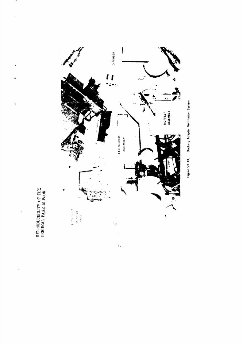
8/8/2019 MSFC Skylab Structures and Mechanical Systems Mission Evaluation
http://slidepdf.com/reader/full/msfc-skylab-structures-and-mechanical-systems-mission-evaluation 193/348
I i
8/8/2019 MSFC Skylab Structures and Mechanical Systems Mission Evaluation
http://slidepdf.com/reader/full/msfc-skylab-structures-and-mechanical-systems-mission-evaluation 194/348
lhe qualification tests consisted of sine evaluation, vehicle dynamics
and high and low level random vibration. A perfornmnce test w_, conducted
prior to and after the vibration tests. The performance test consisted
of an acoustic noise test. During the initial noise test, the muf!i_r
attenuation of fan noise did not meet the required level. The acou_tlc
criteria were re-evaluated and new criteria were incorporated i_ the test
specification. Testing was resumed. The test units successfully passed
the testq.
DeveLopment tests of the diffuser were conducted to verify the
capability of the diffuser to provide the required distribution of air
flow in the docking _dapter. This requirement specified that the air
velocity range at t....crew work stations be between 15 to i00 fpm. Initi,'i
development testing of the diffuser was condJcted by MSFC. Flow tests
were run at 5 and _4.7 psia. Based on the test results, it was
concluded that a 5-in. neck diameter diffuser should be used for the
docking adapter. A system air distribution test was conducted using an
off-the-shelf diffuser of this size, _d!fled to conform to structural
and human enginee,ing design requirementa of the dockixLg adapter. A
mockup of the command and service module and alrlock v -e mated with
the engineering mockup of the docking adapte: for the system Mr dJstxi_ution
test. The docking adapter and the mirlock structural Lrarsltic_, ©=ction
were outfitted with the best available fidelity of in;ernal hardware
ahd experiment packages. The diffusers were ins=all_d and _ositioned
in the : 5jht conf guration. A mapping of the dockir,g adapter/
structural transition section air velo:ity profile was made. The
distrJbution ,:haracteristics were determiped by observation of smoke
cloud dispersion and by taking velocity measurements. The test re_ulcs
verified the system capability to maintain the air velocity requirements
at the crew station.
The diffuser test consisted of a performance test, a vehicle dynamic_low frequency sinusoidal teot_ a high level random vibration test,
and a low level random vibration test. The performance test _as
cundu,'ted prior to mid after the diffuser was tested in each axis of
vibration The performance test procedure was a manual adjustment of the
control knob from one extreme position to the other.
A mechanic:l failure of the diffu er occurred durin_ the high level
ran ff,m vibration tests. A failure analysis disclosed that the structural
_upp, ct hangers for the movable cone of the diffuser sl_ ,ped out of their
installed position. A modification was made to the dit_,_ser desi_ in
which the hangers of the movable cone were welded to the interfacing detail
part to form aN integral assembly. A complete qualification retest of
the diffuser was conducted wit[. t any subsequent fallt_res.
177
8/8/2019 MSFC Skylab Structures and Mechanical Systems Mission Evaluation
http://slidepdf.com/reader/full/msfc-skylab-structures-and-mechanical-systems-mission-evaluation 195/348
1 I 1 I
The fan shroud qualification testing included vibration and shock
tests oi _he fan assembly when mounted in the docking adapter muffler
assembly. The fan assembly successfully passed these tests.
The crews evaluation of the performance of the ventilation system
was; the air circulation was more than adequate, the screens on the
inlet mufflers were an ideal size for collecting dust and debris, and
the operaticn of the fan-muffler assemblies produced a low level
=_ou_tic noise output. It was very quiet. The fans operated as much
as 1500-hr longer than the design life of 3360 hr because of unscheduled
use as rate gyro-slx-pack cooling fans and the extended third manned
mission.
No pr,,blems existed with any of the system hardware.
b. Telescope mount control and display panel/earth
resources observation coolant system. The telesc=pe mount control anddisplay panel earth observation/resources coolant system design requirements
were specified in several documents because the system crossed several
interfaces. The consolidated requirements are:
• Operating pressure--37.2 psla maximum.
• Inlet fluid temperature--49 to 78 eF.
• Fluid--high purity water plus additives.
• Flow rate--220 ib/hr, minimum
• Allowable pressure drop--6.75 psia at 220 Ib/hr.
• Leakage--35 in3 (from time of fill to end of 240-day
mission).
The telescope mount control and dlsplay/earth resources/observation
coolant system consists of the hard tubing, flexible lines, valves, and cold
plates associated with conducting a flow of coolant to and from the
telescope -_unt control and display panel, the earth resources/observation
tape recorders, the earth resources/observation control and display panel, and
the S192 electronics. Docking adapter mechanical components included in the
system are a four-port manual selector valve and earth resources/observation
flexible lines. The docking adapter system interfaces with the airlock system
that contains the pumps, heat exchangers, and accumulator. Configuration
C - ._ 178
!
' J , J J J I J

8/8/2019 MSFC Skylab Structures and Mechanical Systems Mission Evaluation
http://slidepdf.com/reader/full/msfc-skylab-structures-and-mechanical-systems-mission-evaluation 196/348
of the components is shown in Figures VF-14 and VF-15.
Heat loads generated by components are tcansported by means of thecoolant loop to the airlock coolant system from which heat is rejected to
space by means of the airlock/docking adapter radiator system.
Fluid flow through the telescope mount control and display panel is
controlled by positioning the four port manual selector valve. Flow control
through the subsystem is accomplished by balancing flow orificesand the tape recorder selector valve.
The four-port selector valve is an adaptation of the Apollo glycol
bypass valve. The Skylab design modification consisted of removing
the electrical actuator and replacing it with a manually operated
actuator. The fluid control portion of the two va)ves, including thepressure relief mechanism, is identical.
Development tests were performed primarily on the manual actuating
mechanism. Life cycle tests were conducted to demonstrate capability
to withstand the required number of operating cycles plus margin
(475 wet cycles and 25 dry cycles). The actuating mechanism, including
the position locks, performed all cycles without malfunction and only
a slight marking was witnessed as indication of wear. _ibration testing
was also conducted to verify that both the actuating mechanism and
fluid control portion of the valve would not degrade under specifiedvibration conditions.
There was no structural degradation as a result of this test and
the valve performed well durin8 functional tests following
vibration. There wss no measurable internal leakage at operating
pressures using volutetric displacement and nitrogen gas. Also, therewas no degradation of the pressure relief mechanism as a result of
the vibration testing. Relief pressures remained the same as pressures
recorded prior to starting the test.
The four-port selector valve qualification tests consisted of physical
inspection, proof pressure, over torque, ultimate torque, vibration,
life cycle, and burst pressure. A performance test was conducted prior
to and after each environmental test. There were no problems encountered
during qualification testing.
At the completion of qualification testin_ one of the two test units
had no detectable internal leakage and the second unit had a leakage
rate of 0.8 sec (GN2) in 15 min. External leakages for the first
and second units were 9.2 x 10 -9 see/see (He) and 2.3 x 10 -6 see/see (He),respectlve]y. The maximum allowable external leak rate was i x 10-4 see/see
(He).
179
l
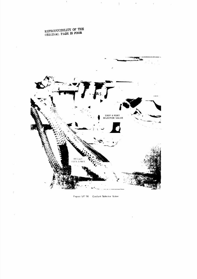
8/8/2019 MSFC Skylab Structures and Mechanical Systems Mission Evaluation
http://slidepdf.com/reader/full/msfc-skylab-structures-and-mechanical-systems-mission-evaluation 197/348
l
REPRODUCIBILITY OF THe]
ORI(;INALPA(_B ISPOOR
Fiqure VF 14 Co(.)ldl lt Sele(:to_ Valve
i
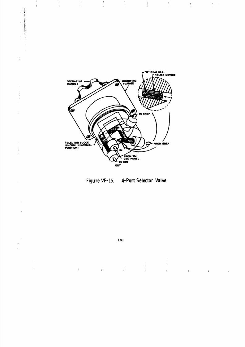
8/8/2019 MSFC Skylab Structures and Mechanical Systems Mission Evaluation
http://slidepdf.com/reader/full/msfc-skylab-structures-and-mechanical-systems-mission-evaluation 198/348
r."O '' RING ilEAL
/ eRE.. LIEF DEVICE
OPERATI_qG MOUNTING :_
HANDLE FLAN6| t J
SELE(:TOR BLOCK FROM EREP(SHOWN INPOSITIONI
:ROM TM
CIkD PANELro irm
OUT
FigureVF-15. 4-PortSelectorValve
181
J i _ I 1 , , i
8/8/2019 MSFC Skylab Structures and Mechanical Systems Mission Evaluation
http://slidepdf.com/reader/full/msfc-skylab-structures-and-mechanical-systems-mission-evaluation 199/348
The qualification tests conducted on the telescope mount control and display
panel flexible coolant lin-_ were: pressure drop, first pressure f_.tigue,
vibration, flexing, second pressure fatigue, and burst pressure. Performance
tests consisting of proof pressure and a leakage test were conducted prior to
and after each _aJor test. There were no problems encountered during
qualification testing.
At the completion of the qualification testing, the two test units
were leak tested. A net leakage of 3.6 x 10 -9 scc/sec (He) was
measured on one unit and 1.0 x 10 -6 scc/sec (He) was measured on the
second. The maximum allowable leakage was 2.0 x 10⁻⁴ scc/sec (He).
Qualification of the earth observation coolant system flexible hoses
was by similarity to several hoses qualified for use in the airlock.
The size_ and configuration_ _f the alrlock hoses were sufficient
to bracket the configurations _elected for the docking adapter and
the structural, environmental, and functional requirements either metor exceeded the docking requirements for the earth resources/observatlon
coolant system hoses.
Development tests were not conducted on the earth resources/observation
tape recorder selector valve because the design had been proven in previous
development and qualification testing required by other NASA programs
on similar valves.
Qualification tests consisted of a vibration test followed by visual
inspection and leakage tests. There was no evidence of physical
damage, water leakage, or change in handle position, as a result of the
testing. Therefore, the tests were considered successful. The test unit
was subjected to a high level random criteria of 10.4 g rms for 5 min
in each of three axe_.
Flow and pressure drop and leakage tests were the only complete
coolant loop system tests performed on the flight article. No specific
thermal loop flow tests were performed, since "off module" tests of
experiment assemblies showed that thermal performance was satisfactory
when the coolant flow and inlet temperature was within specified limits.
Flow balance and distribution was demonstrated by power operation of
the earth resources/observation modules with tubing suriace temperature
measurements during systems tests at MDAC-E.
Leakage tests "on module" were performed to a "volumetrics" measurement
limit of 1.0 x 10⁻³ scc/sec of N2. The volumetrics test method verlfLedall Joints (144) in the coolant system for the airlock interface.
The "volumetrics" instrument showed a high sensitivity to temperature,
such that the entire system had to be wrapped with a super insulation
blanket, all lights turned off inside the docking adapter, and all personnel
restricted from the test area durin E conduct of system leakage.
182
J i i J i , j
8/8/2019 MSFC Skylab Structures and Mechanical Systems Mission Evaluation
http://slidepdf.com/reader/full/msfc-skylab-structures-and-mechanical-systems-mission-evaluation 200/348
In order t_ achieve an acceptable "volumetrics" measurement, a
helium mass spectrometer probe (sniffer) test to a maximum reading of
2.5 x i0 scc/sec was imposed as the system build was in process. Durin G
the system checkout, this probe test requirement was relaxed to 5 x I0-I
scc/sec helium, which still allowed sufficient volumetrics test margin.
Design cycle llfe of the four-port selector valve was 375 cycles.
During the three manned missions, a total of 75 cycles were accumulated.
The tape recorder selector valve has a design cycle llfe of 470 cycles.
During the Skylab mission a total of 6 cycles were accumulated on this valve.
The docking adapter coolant system operated in a normal manner with no
anomalies. No leakage was evident during system operation.
c. Docking adapter vent System - The docking adapter vent system
design requirements are: The docking adapter shall be equipped
with series redundant, remotely-operated vent valves. The valves shall
be sized to ensure that the maximum shell pressure will not exceed 6.2 psid
during laumch of the first unmanned phase. The vent valves shall be
provided with a plug which shall be installed by the crew. Venting
studies were performed to predict the internal docking adapter pressure
during launch. The maximum pressure predicted by analysis was 5.3 PSid.
The actual results during launch/ascent phase were 5.25 psld.
The docking adapter vent system consists of two 4-in. motor operated
vent valves mounted in serles t one sealing device, and one stowage fitting.
The vent valves provide a means of venting the docking adapter and airlock
during prelaunch, launch, and ascent. The valves are opened prior to
launch and closed during ascent, via instrument unit command,
to maintain a positive pressure within the alrlock/docking adapter.
The vent sealing device provides a positive sealing capability
of the vent valves during orbital operation. The sealing device isinstalled by the astronauts upon their initial entry into the docking
adapter during the first manned phase. The vent system is illustrated
in Figures VF-16 and VF-17.
Examples of development tests conducted on the 4-1n. vent valve
(FiRure VF-18) are: internal and external leakage, electrical checks,
high and low temperature operation, life cycle and vibratlon. This unit
successfully completed the tests wlth results that either met or exceeded
the specification requirements.
The qualification testing consisted of the following environmental
tests: CCOI[, vibration, shock, vacuum storage, explosive atmosphere,
burst pressure, and life cycle. A perfo_nance test was conducted after
each environmental test. The problems encountered during qualification
testing are summarized below.
183
A t
J ,i |
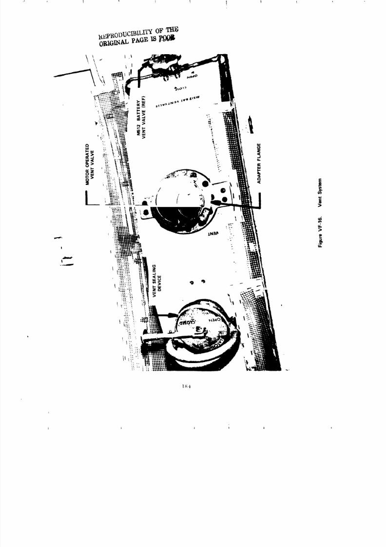
8/8/2019 MSFC Skylab Structures and Mechanical Systems Mission Evaluation
http://slidepdf.com/reader/full/msfc-skylab-structures-and-mechanical-systems-mission-evaluation 201/348
I_#I_ODI]CIBILI_F
1_4
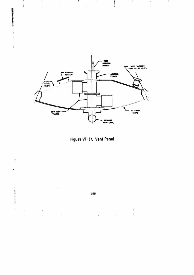
8/8/2019 MSFC Skylab Structures and Mechanical Systems Mission Evaluation
http://slidepdf.com/reader/full/msfc-skylab-structures-and-mechanical-systems-mission-evaluation 202/348
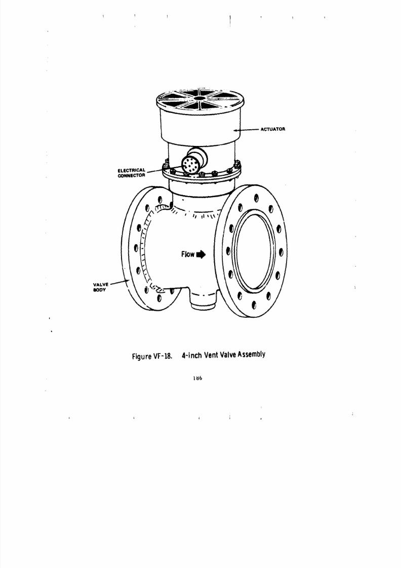
8/8/2019 MSFC Skylab Structures and Mechanical Systems Mission Evaluation
http://slidepdf.com/reader/full/msfc-skylab-structures-and-mechanical-systems-mission-evaluation 203/348
ACTUATOR
ELECTRICAL
CONNECTOR
VALVEBODY
I
FigureVF-t8. 4-inchVentValveAssembly
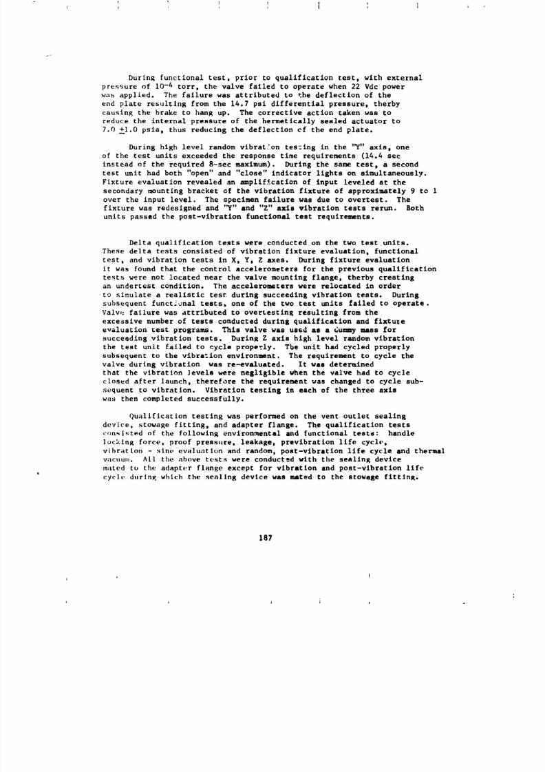
8/8/2019 MSFC Skylab Structures and Mechanical Systems Mission Evaluation
http://slidepdf.com/reader/full/msfc-skylab-structures-and-mechanical-systems-mission-evaluation 204/348
During functional test, prior to qualification test, with external
pressure of 10-4 torr, the valve failed to operate when 22 Vdc power
was applied. The failure was attributed to the deflection of the
end plate restilting from the 14.7 psi differential pressure, therby
causing the brake to hang up. The corrective action taken was toreduce the internal pressure of the hermetically sealed actuator to
7.0 _i.0 psia, thus reducing the deflection cf the end plate.
During high level random vibration tes=ing in the '_" axis, one
of the test units exceeded the response time requirements (14.4 see
instead of the required 8-set maximum). During the same test, a second
test unit had both "open" and "close" indicator lights on slmultaneously.
Fixture evaluation revealed an amplification of input leveled at the
secondary mounting bracket of the vibration fixture of approximately 9 to 1
over the input level. The specimen failure was due to overtest. The
fixture was redesigned and '_" and "Z" axis vibration tests rerun. Both
units passed the post-vibration functional test requirements.
Delta qualification tests were conducted on the two test units.
These delta tests consisted of vibration fixture evaluation, functional
test, and vibration tests in X, Y, Z axes. During fixture evaluation
it was found that the control accelerometers for the previous qualification
tests were not located near the valve mounting flange, therby creatingan undertest condition. The accelerometers were relocated in order
to simulate a realistic test during succeeding vibration tests. During
subsequent functional tests, one of the two test units failed to operate.
Valv,_ failure was attributed to overtesting resulting from the
excessive number of tests conducted during qualification and fixtule
evaluation test programs. This valve was used as a dummy mass for
succeading vibration tests. During Z axis high level random vibration
the test unit failed to cycle properly. The unit had cycled properly
subsequent to the vibration environment. The requirement to cycle the
valve during vibration was re-evaluated. It was determined
that the vibration levels were negligible when the valve had to cycle
closed after launch, therefore the requirement was changed to cycle sub-
sequent to vibration. Vibration testing in each of the three axis
was then completed successfully.
Qualification testing was performed on the vent outlet sealing
device, stowage fitting, and adapter flange. The qualification tests
consisted of the following environmental and functional tests: handle
]ocklng force, proof pressure, leakage, prevlbration life cycle,
vibration - sine evaluation and random, post-vibration llfe cycle and thermal
vacuum. All the above tests were conducted with the sealing devicemated to the adapter flange except for vibration and post-vibration life
cycle during which the sealing device was mated to the stowage fittln_.
187
t l l i a ,
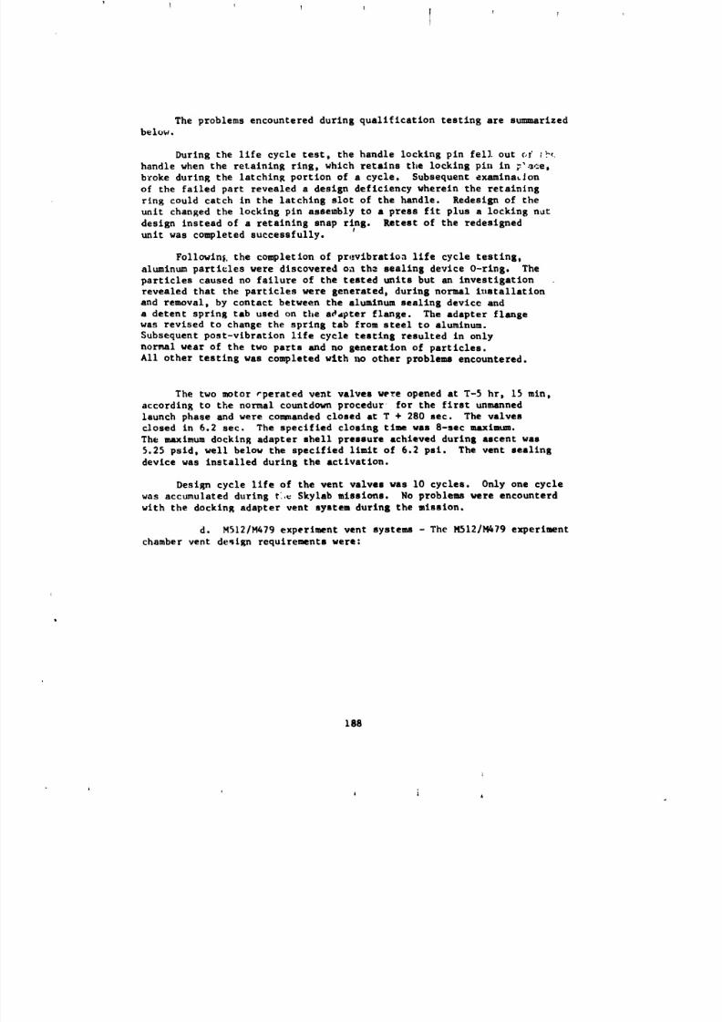
8/8/2019 MSFC Skylab Structures and Mechanical Systems Mission Evaluation
http://slidepdf.com/reader/full/msfc-skylab-structures-and-mechanical-systems-mission-evaluation 205/348
l I ! v
I II
The problems encountered during qualification testing are su_aarizedbelo_i.
During the life cycle test, the handle locking pin fell out of ;_
handle when the retaining ring, which retalns the locking pin in _'ace,
broke during the latching portion of a cycle, Subsequent examination
of the failed part revealed a design deficiency wherein the retaining
ring could catch in the latching slot of the handle. Redesign of the
unit changed the locking pin assembly to a press fit plus a locking n_t
design instead of a retaining snap ring. Retest of the redesignedunit was completed successfully.
Following the completion of prevlbration life cycle testing,
aluminum particles were discovered on th_ sealing device O-ring. The
particles caused no failure of the teated units but an investigation
revealed that the particles were generated, during normal l_Latallation
and removal, by contact between the aluminum sealing device anda detent spring tab used on the addpter flange. The adapter flangewas revised to change the spring tab from steel to aluminum.
Subsequent post-vibration life cycle testing resulted in only
normal wear of the two parts and no generation of particles.
All other testing was completed with _w other problems encountered.
The two motor rperated vent valves were opened at T-5 hr, 15 min,according to the normal countdown proeedur for the first unmanned
launch phase and were commanded closed at T + 280 sec. The valves
closed in 6.2 sec. The specified closing time was 8-see maximua.The maximum docking adapter shell pressure achieved during ascent was
5.25 psid, well below the specified limit of 6.2 psi. The vent sealing
device was installed during the activation.
Design cycle life of the vent valves was I0 cycles. Only one cycle
was accumulated during t:_ $kylab missions. No problems were encounterd
with the docking adapter vent system during the mission.
d. M512/M479 experiment vent systems - The MSI2/M479 experiment
chamber vent design requirements were:
lg8
i
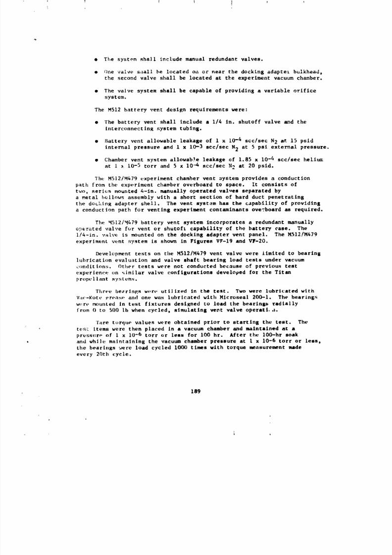
8/8/2019 MSFC Skylab Structures and Mechanical Systems Mission Evaluation
http://slidepdf.com/reader/full/msfc-skylab-structures-and-mechanical-systems-mission-evaluation 206/348
• The systom shall include manual redundant valves.
• One valve shall be located on or near the docking adapter bulkhead_
the second valve shall be located at the experiment vacuum chamber.
• The valve system shall be capable of providing a variable orifice
system.
The M512 battery vent design requirements were:
• The battery vent shall include a 1/4 in. shutoff valve and the
interconnecting system tubing.
• Battery vent allowable leakage of I x 10-4 see/see N2 at 15 psld
internal pressure and 1 x 10⁻³ scc/sec N2 at 5 psi external pressure.
• Chamber vent system allowab!e leakage of 1.85 x 10 -4 scc/sec helium
at 1 x 10⁻⁵ tort and 5 x 10 4 scc/sec N2 at 20 psid.
The MSI2/M479 experiment chamber vent system provides a conduction
path from the experiment chamber overboard to space. It consists of
two, series mounted 4-in. manually operated val,,es separated by
a metal bellows assembly with a short section of hard duct penetrating
the docking adapter shell. The vent system has the capability of providing
a conduction path for venting experiment contaminants overboard as required.
The _512/_479 battery vent system incorporates a redundant manually
operated valve for vent or shutoft capability of the battery case. The
i/4-in, valve is mounted on the docking adapter vent panel. The M512/M479
experiment vent system is shown in Figures VF-19 and VF-20.
Development tests on the blS12/M479 vent valve were limited to bearing
lubrication evaluation and valve shaft bearing load tests under vacuum
conditions. Other tests were not conducted because of previous test
experience on _imilar valve configurations developed for the Titan
propellant systems.
rhrre be_rlngs wert, utilized in the test. Two were lubricated with
Var-Kote _,roaso and one was lubricated with Hlcroseal 200-1. The bearings
were mounted in test fixtures designed to load the bearingb radially
from O to 500 Ib when cycled_ simulating ve_t valve operati,.t.
rare torque values were obtained prior to starting the test. The
' tes_ items were then placed in a vacuum chamber and maintained at a
pressuro of I x 10-6 torr or less for 100 hr. After the lO0-hr soak
and while maintaining the vacuum chamber pressure at 1 x 10⁻⁶ torr or leas,
the bearings _ere load cycled 1000 times with torque measurement made
every 20th cycle.
189
8/8/2019 MSFC Skylab Structures and Mechanical Systems Mission Evaluation
http://slidepdf.com/reader/full/msfc-skylab-structures-and-mechanical-systems-mission-evaluation 207/348
1 f
FigureVF-19. 4-InchChamberentValve
/
\FigureVI--20. MS]211V;479entSystem
_0
i J i A
8/8/2019 MSFC Skylab Structures and Mechanical Systems Mission Evaluation
http://slidepdf.com/reader/full/msfc-skylab-structures-and-mechanical-systems-mission-evaluation 208/348
8/8/2019 MSFC Skylab Structures and Mechanical Systems Mission Evaluation
http://slidepdf.com/reader/full/msfc-skylab-structures-and-mechanical-systems-mission-evaluation 209/348
1 _ I I i
The qualification tests were all successfully accomplished, without
difficulty, on both bellows tested. The two bellows passed the internal
leakage rate of i x 10-8 scc/sec (max.), the i000 cycles test, the proof
pressure test of 32 psi_ for 3 nln, and the internal burst pressure
of 52 psig for i mln. One bellows was subjected to an external pressure
test {the tube collapsed at 60 pslg). The other bellows was subjected
to an internal rupture cest (at 300 psig, the bellows did not rupture),
only the convolutes of the bellows "squirmed" to a permanent ,set.
Development tests of the M512 battery vent valve (1/4 in.) consisted
of the following tests: weight, proof pressure, external leakage,
operating torque, internal leakage, life cycling, pressure drop,
vibration, shear torque, and burst pressure. The unit completed the develop-
ment tests with results that met or exceeded the specification requirements.
Subsequent to develop:.mnt testing, the vibratYon levels were revised
and it was determined that the Vespel seal material was incompatible with
potassium hydroxide (KOH) vapors given off by the MSI2/M479 battery.
Consequently, the design specification was revised to reflect the new
vibration levels and the valve seat material was changed from Vespel to
KeI-F.
The qualification consisted of the following tests: salt spray,
pressure drop, temperature, life cycle, vibration (closed), vibration
(open), thermal vacuum, flow versus handle position, shear torque, and burst
pressure. Subsequent to each vibration test, a functional test consisting
of proof pressure, internal leakage, and external leakage was performed.
The only anomaly occurring in qualification testing was excessive
leakage attributed to frost buildup on the valve seat during a post-
vibration functional test. The test personnel were cautioned to
follow specific evacuation and purge times prior to performing a test.
Three unitq successfully completed qualification testing with results
that met or exceeded the design specification criteria.
During a docking adapter flight article system leakage test, anomalies
occurred on the M512/M479 work chamber vent valves and on the battery
vent valve.
The purpcse of the test was to verify that the internal leakage
of each of the two work chamber vent valves had remained within the
allowable range, that the external leakage of the total chamber vent
system was within the allowable range, and to verify that the
battery vent llne and valve leakage rates were within the allowable range.
]92
I
8/8/2019 MSFC Skylab Structures and Mechanical Systems Mission Evaluation
http://slidepdf.com/reader/full/msfc-skylab-structures-and-mechanical-systems-mission-evaluation 210/348
During performance of the system leak checks, valve #i (at the
work chamber) had no detectable leakage using the volumetrics leak
detector and valve #2 (at vent elbow) had a leak rate too large to
measure. The a]lowable rate is less than 1 x 10⁻⁴ scc/sec (GN2>.
Valve #2 was removed for failure analysis. Since there was obvious
contamination on the rejected valve seat, the bellows assembly was also
rejected for suspected con_amlnation. Both rejected items were replaced
in the vent system. Retest of Valve #2 <replacement item) resulted in
no indicated leakage.
External leakage of the work chamber and vent line is measured
by evatuating the chamber and vent llne through a CEC helium leak detector,
by externally bagging the chamber and vent llne, and by filling the bag with
helium. The measured leak rate for the total chamber vent system was
1.4 x 10⁻⁸ scc/sec (He) and the allowable rate is less than 3.7 x 10⁻⁶
scc/sec (He).
Leakage verification of the MSI2/M479 battery _ent valve resulted
in rejection of the vent valve for excessive internal leakage. The
measured leak rate was 1.06 scc/sec (GN2) and the allowable leak rate
was 0.4 scc/sec (GN2). The valve was rejected and failure analysis
conducted. The results of the analysis revealed that the excessive leakage
was caused by contamination imbedded in the valve seat. The rejected
valve was replaced in the system with another valve and the leak test
rerun. The re-test was successful with a measured leak rate of 0.47 x 10⁻⁷
scc/sec (GN2).
Design cycle life of the 4-in. vent _alve was i00 cycles; 69 cycles
were accumulated during flight. Cycle llfe of the i/4-in, battecy
vent valve was lO cycles; one cycle was accumulated during flight.
The M512 vent system operated properly during all Skylab missions.
No leakage or hardware problems were encountered.
The chamber pressure was maintained at less than 1 x 10 -4 tort as required
during all experiment operations.
193
j I 4 J i _ J
8/8/2019 MSFC Skylab Structures and Mechanical Systems Mission Evaluation
http://slidepdf.com/reader/full/msfc-skylab-structures-and-mechanical-systems-mission-evaluation 211/348
! ill Ii I i I
!
8. Rate Cyro 6-Pack
During the first manned phases and the second unmanned period, there
were indications that the Skylab rate gyros located in the telescope mount
were not performing well and it was speculated that their environment
could be the problem. A recommendation was made by the technical area
responsible for the gyros, Astrionics Laboratory.(MSFC), to install a new set
of rate gyros somewhere inside the Skylab that would replace the mal-
functioning rate gyros. The telescope mount rate gyro system consisted of
two gyros in each of the three axes or a total of six; thus, the name "Rate
Gyro 6-pack".
The most feasible installation location for the gyro pack was
determined to be in the docking adapter. The specific area chosen was the
area reserved for the N_. film retrieval tre_ launch/mission stowage. Thetree could be stowed elsewhere. This location in the docking adapter was
selected because: (i) it was on one of the axes, (2) there were four
hard point locations for attachment to the main docking adapter structure,
(3) the installation required no special tools, (4) the gyro package would
have minimal effect on the other system, and (5) a power connector was
adjacent to the location, thus cable routing from the gyro pack to the C&D
console could be made with minimum difficulty.
Responsibility for the design of the slx-pack primary base mounting
assembly was assigned to the S&M MSG. One axis system [2 gyros) would
be installed on this plate. The other two axis systems (4 gyros)
would be mounted on another plate assembled to the primary base plate,
using alignment pins and captive fasteners. The design responsibility
for these other two axis systems was assigned to the Astrlonlcs Laboratory.
One of the early requirements was to make the base plate adjustable
in three axes to provide precise alignment. A preliminary design was
made for this configuratJon consisting of a firm base; two intermediate
plates, which provided f_r two axes adjustment; and a gyro mounting plate,
which provided the third axis adjustment. This design would require a
coDsiderable amount of operational time to install. An additional
requirement was that the installed assembly have a natural frequency of
gLeater than i0 llz. This meant that the adjustable components must necessarily
be heavy which led to making a tolerance study of the "worst case" mis-
alignments to be ehcountered from the structural design of the Clocking
adapter mounting provisions and a non-adjustable base plate. The results
of this study indicated that the "worst case" misaliKnment could be
0°42 ' in the worst axis. The Astrionics Laboratory indicated that a 1°
mlsalignment could be tolerated. Based on this study, the slx-pack
rste gyro base was made a non-adjustable plate.
194
8/8/2019 MSFC Skylab Structures and Mechanical Systems Mission Evaluation
http://slidepdf.com/reader/full/msfc-skylab-structures-and-mechanical-systems-mission-evaluation 212/348
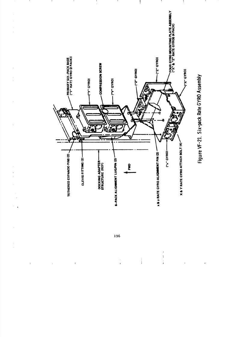
8/8/2019 MSFC Skylab Structures and Mechanical Systems Mission Evaluation
http://slidepdf.com/reader/full/msfc-skylab-structures-and-mechanical-systems-mission-evaluation 213/348
I 1 t 1 1
196
J j I *

8/8/2019 MSFC Skylab Structures and Mechanical Systems Mission Evaluation
http://slidepdf.com/reader/full/msfc-skylab-structures-and-mechanical-systems-mission-evaluation 214/348
! ! T I I 1 ]
Although all systems met all on-orbit requirements, there were problems
encounter,.d during ground testing of the telescope mount coolant system
and hatch pressure gage; therefore, the following recommendations
are made:
1) All metals used for construction of active coolant systems should
belong to the same family group of dissimilar metals; this would
eliminate'unnecessary dlscussioh and testing as to the effects
of corrosion, and 2) if a visual mechanical pressure gage is required,
one must pay close attention tc the shock environment and the accuracy
requirement; if the maximum shock is on the order of 1500 g's, then the
accuracy requirement should be at least 0.i psld; this would allow
a ga_e to be designed with a greater pressure range and, therefore,
a stiffer bourdon tube which would be less susceptible to gravity
effects and shock testing practices.
The mechanical actuator and latch for the S190 window cover functionedrellably throughout the mission. The second Skylab crew remarked that
the mechanism operated easily. The use of such mechanical actuators is
recommended for future vehicle designs as a simple and reliable means
for controlling external components.
The importance of screening structural glass windows to detect
invisible flaws was discovered In the process of designing the S190 window.
Consequently, all windows in the docking adapter were flaw screened to eliminate
any glass containing flaws that might grow to a critical size during the
Skylab mission The preferred method for flaw screening pressurized windows
is pressure te_ting to simulate the operating stress distribution. Thermal
shock testing had also been used for flaw screening, but it overstresses the
edges of the window and may result in unnecessary test failures. All docking
adapter windows functioned normally during the Skylab missions.
Another lesson learned in designing the S190 window was that structural
wim,ows needed prolaunch protection to prevent damage following acceptance
testing. _;u<'l_amage had occurred on earlier programs. In the docking
adapter program, all windows were supplied with protective covers from time
of installation until Just before launch. Removal of the covers to perform
tests or maintenance was controlled by procedures. Consequently, no docking
adapter windows were damaged after installation.
Some of the blind nuts used to attach equipment to the 1ongerons caused
problems duzlng manufacture of the docking adapter. The reason for this
was removal and replacement of some items causing unexpected re-use of the
nuts whici_ exceeded their capabilities. This resulted in galling in the self-
locking threads, and occasional bolt failure. Rework of the failed
nuts Lnw)Ived careful controls to prevent contamlnat_on by chips and loose
parts, which complicated tim manufacturing process. It is recommended that
all equipm_.nt that may be replaced prior to launch be attached with easily
rq,placeable har,lware.
197
8/8/2019 MSFC Skylab Structures and Mechanical Systems Mission Evaluation
http://slidepdf.com/reader/full/msfc-skylab-structures-and-mechanical-systems-mission-evaluation 215/348

8/8/2019 MSFC Skylab Structures and Mechanical Systems Mission Evaluation
http://slidepdf.com/reader/full/msfc-skylab-structures-and-mechanical-systems-mission-evaluation 216/348
199
L
8/8/2019 MSFC Skylab Structures and Mechanical Systems Mission Evaluation
http://slidepdf.com/reader/full/msfc-skylab-structures-and-mechanical-systems-mission-evaluation 217/348
i
2. Wardroom Window.
a. General requirements. The wardroom window, approximately
18 in. in diameter, was in,=orporated in the workshop crew quarters
area to allow crew vlewing as well as hand held and S063 photography.
The window is fused silica dual pane glass with the inner pane
heated to prevent condensation on the inside surface. An in-
ternally mounted metal cover sustained launch and ascent pressure
and provided an extra measure of protection during unmanned periods.
Also included is a shade to shut out light when desired and a
transparent impact shield for protection when not involved with
photography.
Figure VG2-1 presents an exploded view of the window with associated
hardware.
b. Mission performance. The wardroom window withstood the
launch and boost environments and performed all required functions for
the mission. The occurrence of moisture and ice within the cavity on
the inboard side of the outboard pane did require periodic remove! of
condensate by the crew as described in detail in the fol.owirg paragraph.
c. Anomalies.
(i) Workaround. During initial activation, the first manned
crew observed the presence of ice and moisture in the cavity between the
panes of the wardroom window. Several ground studies were conducted
in an effort to solve the problem utilizing new procedures and on-
board equipment. It was determined that the improvement of visibility
would not justify the required impact on the crews time utilizing
available equipment. An evacuation fitting was developed, flown
up by the second crew, and installed in the purge fitting
of the window (Figure VG2-2). The procedure called for
venting the cavity to vacuum through the -Z scientific alrlock
and backfilling the cavity with desiccated air from the -Z scientific
alrlock desiccant canister. When the moisture was removed, an area of
discoloration or residue remained. The moisture reappeared after
about 7 days and the procedure was revised to eliminate the backfill,
but the moisture continued reappearing every 6 to i0 days. The final
procedure called for the evacuation fittlng to remain Installed in
20O
I
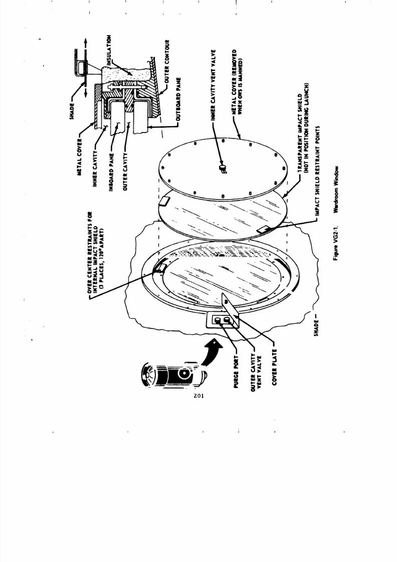
8/8/2019 MSFC Skylab Structures and Mechanical Systems Mission Evaluation
http://slidepdf.com/reader/full/msfc-skylab-structures-and-mechanical-systems-mission-evaluation 218/348
I 1 1 I !/

8/8/2019 MSFC Skylab Structures and Mechanical Systems Mission Evaluation
http://slidepdf.com/reader/full/msfc-skylab-structures-and-mechanical-systems-mission-evaluation 219/348
ZOZ
8/8/2019 MSFC Skylab Structures and Mechanical Systems Mission Evaluation
http://slidepdf.com/reader/full/msfc-skylab-structures-and-mechanical-systems-mission-evaluation 220/348
1 _ f I v !
I I i I
the purge port and the line to be connected to the -Z scientific airlock
by the crew when required. Nhen the procedtre was completed, the =lne
from the evacuation fitting to the -Z scientific airlock was disconnectedat both points. The removal of ice and moisture by sublinmtion and
evaporation took 5 to lO minutes, however the cavity remained vented
to vacuum up to 3 hours to establish as complete an evacuation
of the cavity as possible.
(2) Troubleshooting. The history of the window t_as re-
searched to determine how and when the cavity contamination might have
occurred. The procedures for handling, cleaning, testing, and installation
indicate that contamination was not present up through installation of the
window assembly in the workshop prior to closeout and shipment to KSC.
Subsequent workshop procedures included no requirement for a
contamination check between installation and final KSC closeout.
Therefore, no checks were made to detect its presence.
It is pointed out that the valve O-ring could have possibly
been damaged after the installation leak test was accomplished.
Also, since the outer cavity vent valve (used to equalize outer
cavity pressure at initial activation) had no positive mechanical
lock to prevent tampering between window installation _nd final
closeGut at KSC, tampering is a possibility. The residue or dis-
coloration mentioned in paragraph (1) was possibly the result
of vapor depositaries occurring gradually whenever moisture preset
in the cavity condensed on the window. Subsequent evacuation removed
the moisture, and conditions were set for repetition of the cycle.
The production acceptance tests for the wardroom window
were conducted at HDAC-N, Huntington Beach, when the window wds fully
assembled but not installed. The specification leak rate of1 x I0 -U standard cm3/sec (sccs) was met. Long term leak testing
that would uncover design or nmterlal deficiencies was not conducted
during these tests. However, during checkout prior to shipment
of the workshop to KSC, with the window assembly installed, the
window was checked again and the specified leak rate was again
met. (The test conditions in both cases were He at 75 "F and a
delta pressure of 15.2 _ 0.5 psi.) After each test I atm of dry
N2 was locked in the cavity.
Analysis shows that no significant leakage of moisture
into the cavity would occur ,m orbit with a specification leak rate
of l x lO-6 acts. llow_.ver, the analysis did show that a leak rate
o_ 7.5 x lO -2 sccs would allow a spot of moisture 0.001 to be
for_ed in t},e cavity in 6 to lO days.
d. Rerommend._! ions. On ftlture pro)cots, provisions to evacuate
_;_viti,'_. IJ,.lw,.,.n _la_ ;,.tm.s sh,,uld be included. Also, our anaLysis shows
that _,p,._ it i,.lti,,_R'_, it n,_t c_mpatihle with mission duration, can lead
t,, v,),Ji..t,ir,, ir_l...ti-n. Exist|ng ,.loaning and handling procedures are
:l¢.ct.i,t.ibl, but l,.riodic c.hecks sliollld he made to detect the presence of
c,t_l.itf_in4t/cm a_t_,r final installation.
203

8/8/2019 MSFC Skylab Structures and Mechanical Systems Mission Evaluation
http://slidepdf.com/reader/full/msfc-skylab-structures-and-mechanical-systems-mission-evaluation 221/348
1 1 T 1 1
I
3. Solar Array System. The general requirements for the solararray system, parts of which are a carry-over fr>m the wet workshop
program s are:
a. General requirements.
(I) The solar array system shall deploy at*tcm, tically,
utilizing an ordnance system similar to that developed for the meteoroid
shield, which shall not contaminate or affect the solar cells and other
cluster systems.
(2) The time for deployment to vary from 9-min
maximum (for deployment initiated 20 mln after llft-off) to 14-mln
maximum (for deployment initiated 105 min after lift-off).
(3) The solar array system shall be capable of de_loyment
through backup commands via the airlock module digital command system.
(4) The solar array system shall withstand the loads,
vibrations and shock levels associated with launch, ascent, docking and
maneuvering.
(5) During boost, the wing section cavities within the
beam falrings shall vent through acoustically actuated vent valves.
b. Development and testing.
(I) SA-14 wing zelease. The purpose of this test was to
develop the specific expandable tube and tension strap, or llnk, for releasing
the stowed solar array panels. Although the flight configuration requircs
expandable tubes that are 31 ft in length, extending through the
three lO-ft bays in the solar array system fairing, the test assemtlywas made 39-In. long. This was done to permit vibration of the tubes
that are supported only at cinch-bar positions, that is, approximately
30 in. apart. The required X-ray inspection following vibration environ-
ment revealed that the fuse became separated wlth[n the expandable tube.
On disassembly it was found that the fuse was free to slide within the
assembly and not constrained as intended, The minor redesign that corrected
this problem increased the diameter of the spacers on the fuse so that when
the tube is flattened to the required dxmenslon, the fuse is gripped at
each spacer along its entire length,
Since early in the development phase, the onty time the
expandable tube failed to break a tension llnk in the entire test
program occurred during this test. It was caused by a combination
of two conditions that were subsequently corrected with added controls.
First, it was found that the llnk had been incorrectly manufactured.
The grain direction of the tension link, required by the engineering
204
J A
8/8/2019 MSFC Skylab Structures and Mechanical Systems Mission Evaluation
http://slidepdf.com/reader/full/msfc-skylab-structures-and-mechanical-systems-mission-evaluation 222/348
drawing to run lengthwise (i.e., in the same direction as the expandable tubes)
was, in fact, transverse on several tension links, making the part more
difficult to break. Tension links having a break groove material thick-
ness of O.021-in. were tested and compared to the meteoroid shield
tension strap that had a 0.013 to 0.016-in. break groove.
In addition, it was noted that the fit of the
expandable tubes within the failed tension link was extremely loose. This
meant that some of the tube expansion was wasted since it did not work
a_ainst the ]ink.
(2) SA-15 wing release. The solar array system test
was originally planned as a qualification test of four specimens, but was
revised in scope and was actually performed with one specimen. The single
test specimen consisted of two 10-ft long expandable tubes. They
were installed in the one-third length solar array system beam fairing
development model and exposed to dynamic environments. For this test,
both the primary and backup systems were operated with a programmed
delay between firings of 100 msec.
The system performed as required, severing the five
attach links that secured the stowed solar array system wing section
in a rigged condition. An anomaly was experienced at each tension link;
strips of the aluminum link broke loose either as a primary system
functioned or during functioning of the backup system. The strips
resulted from the straps breaking at the secondary relief grooves
paralleling the intended line of fracture. All louse elements were
retained by a retainer, which is a part of the tension link assembly.
(3) SA-17 solar array system beam fairing release.
This test was established to develop the configuration of expandable
tube and tension strap for solar array beam deployment. This usage
requires a very short expandable tube assembly (approximately 9 in.
overall length) and a tension strap capable of carrying high loads.
The functional test specimen consisted of two expandable
tubes and a tension strap assembly mounted and preloaded in a structural
yoke assembly. The tension strap was adapted from the meteoroid shield
design by increasing the break _roove material thickness to 0.021 in.
Other areas of the strap cross section were proportionally increased.
Results from firing the first nominal-thickness strap
indicated that further modifications to the tension strap were required
because portions along the fracture _roove were broken loose during
firing, a result similar to those of SA-15. All pieces were retainedwithin the yoke and were not construed as fragments.
205
J I J _ i
8/8/2019 MSFC Skylab Structures and Mechanical Systems Mission Evaluation
http://slidepdf.com/reader/full/msfc-skylab-structures-and-mechanical-systems-mission-evaluation 223/348
I
Following revision to the design to reduce the depth
of the machined grooves (allowing the element along the fracture line
to bend), the remaining five specimens with redesigned tension straps
were operated with no further anomalies.
(4) ST-24 expandable tube and tension strap. Special
test 24 was cozLceived as an expeditious way of determining (prior
to performance of solar array system test SA-4) if parts would
break off the tension straps during strap severance. There was concern
because it had been Judged during the manufacture of the expandable tubes
for the SA-4 specimen that the annealed stainless steel tubing was softer
than the prior product end would, therefore, yield greater expansior_
per given explosive charge. This would make the tension strap more
susceptible to developing loose parts along the fracture line during
firing. Special test 24 was run concurrently with the early position
of SA-4.
The tension strap in each specimen was covered with
Scotch 850 aluminized Mylar tape to simulate the passive thermal protection
on flight hardware. In five specimens, aluminum tabs were broken off
by the expandable tube firing, although so little energy was imparted
to them that most _Jere retained by the tape. One room-temperature
specimen had no loose parts resulting from firing.
Final system rigging and qualification testing was
successful from an ordnance standpoint. Qualification testing was performed
at ambient temperature and there were no ruptures or loose pieces
(tabs). As a result of successful firings at ambient temperature, it
was decided that taping the separation joint to retain the tabs wouldnot be necessary.
(5) Acoustic vent module. The vent module (Figures
VC3-1 and VG3-2) was designed to open at one-half the expected acoustic
pressure generated at launch, and to withstand, without opening,
an acoustic pressure level of twice the maximum ambient expected in the
area of the launch site. A relief valve (Figure VG3-3) was in-
corporated to allow venting in case the ground purge pressure exceeded
O.l to 0.4 psJd and as a backup to the main acoustic vent doors.
Site test at KSC, with the test unit, during the launch
of Apollo 16 showed the unit functioned as predicted and designed.
(6) Actuator/damper. The actuator/dampers (FigureVC3-4) used on the beam fairings and wing _ections were similar in
construction, but differed in stored energy and deployment rate.
Extensive testing under various environments was used to develop and
qualify the actuator/dampers.
206

8/8/2019 MSFC Skylab Structures and Mechanical Systems Mission Evaluation
http://slidepdf.com/reader/full/msfc-skylab-structures-and-mechanical-systems-mission-evaluation 224/348
207
i
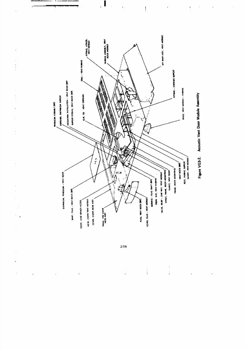
8/8/2019 MSFC Skylab Structures and Mechanical Systems Mission Evaluation
http://slidepdf.com/reader/full/msfc-skylab-structures-and-mechanical-systems-mission-evaluation 225/348
J
Z08
i,
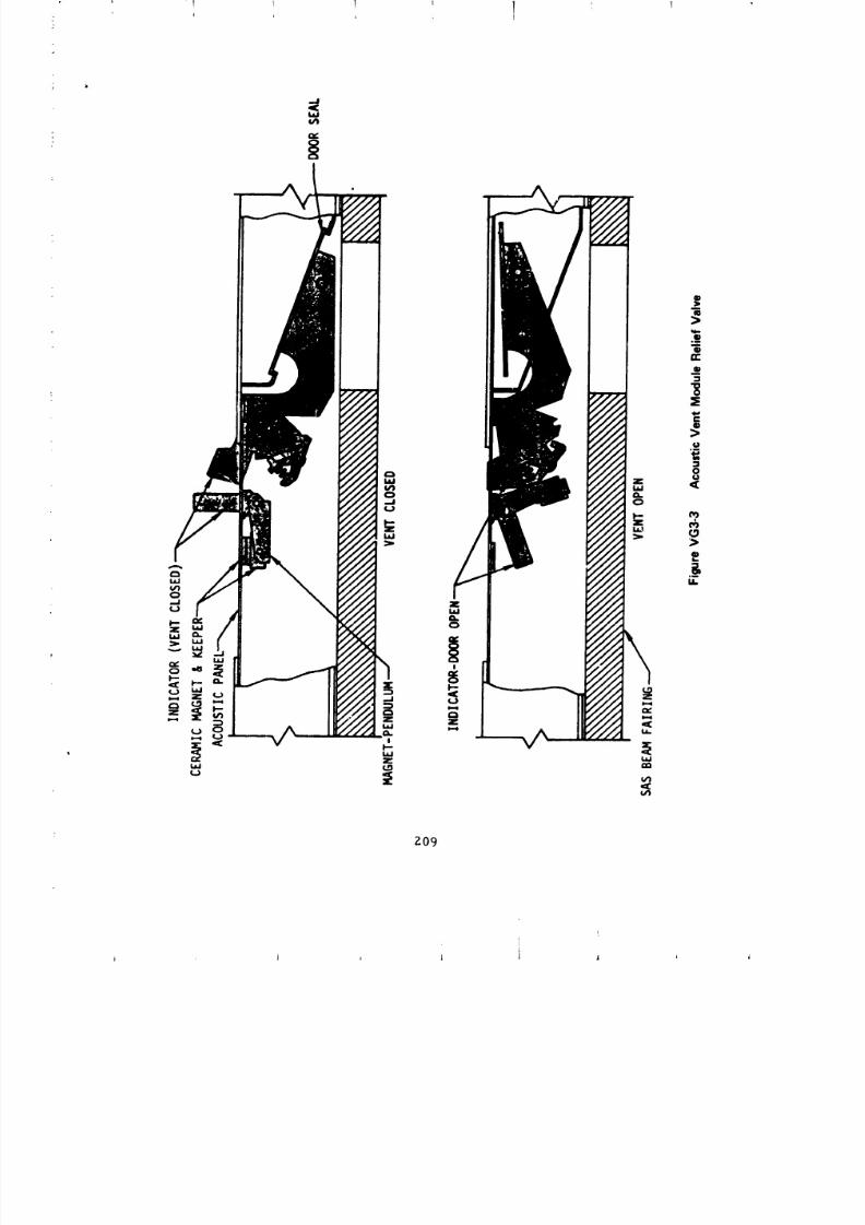
8/8/2019 MSFC Skylab Structures and Mechanical Systems Mission Evaluation
http://slidepdf.com/reader/full/msfc-skylab-structures-and-mechanical-systems-mission-evaluation 226/348
,.,J
/ffJ_,,-jjj
fJfJf/f_
Z09
i
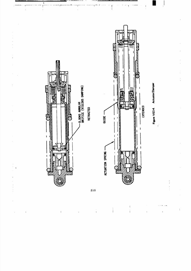
8/8/2019 MSFC Skylab Structures and Mechanical Systems Mission Evaluation
http://slidepdf.com/reader/full/msfc-skylab-structures-and-mechanical-systems-mission-evaluation 227/348
J
m
m
I
I
I I I
ZlO
t
8/8/2019 MSFC Skylab Structures and Mechanical Systems Mission Evaluation
http://slidepdf.com/reader/full/msfc-skylab-structures-and-mechanical-systems-mission-evaluation 228/348

8/8/2019 MSFC Skylab Structures and Mechanical Systems Mission Evaluation
http://slidepdf.com/reader/full/msfc-skylab-structures-and-mechanical-systems-mission-evaluation 229/348
21g
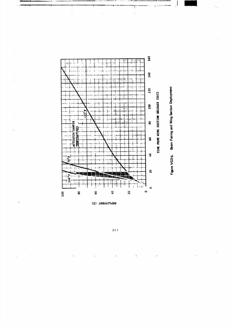
8/8/2019 MSFC Skylab Structures and Mechanical Systems Mission Evaluation
http://slidepdf.com/reader/full/msfc-skylab-structures-and-mechanical-systems-mission-evaluation 230/348
t t i I t ! I 1 i I t I t 1 1!]i F Ii!!i/![i:--.,| ...... I ....... 6.-..t- ...... _ |....: ...... .4....|'. L.--.• '1 I t | : I " ' I ;
r---l-. 4 ........ _........ i . ..... .4-. - '--'t" -4"_ _ --_,-.-t---_' I , I ; I ' , I ,:_-_ I ; ........ i...... ,..,....,.-.._........:.. +--4....
• , " I • i : ' , ".... i • I
-_ _... ................-rr:-__ _I 1_I,:
. :..4%. :-. I ......., i.---i.-.: ....". ...............-..._...-.:.........1...._,__
I ' ' , ' _ I • , • _.....-.i......:'X-....I...................---,----|-.-...---,-.......--4.......• , . , : , • ; t ' _I 0
, __"I" . !........ . . .. .. .. . _'"_l"t ....... r-"t ....... 1-...... :--1-- ,'t:,...... :"'-. .........._--L-_-i:.....--4-L--_._'_ : !i_ _ g
......,..........'_......_........-,i-.-i.._:._.4.....I...'-
, ,. ;,,1_.., _1 :!,1 L _ I , l/3.... •"_f'-'---'"P'"'lr',il'_'I¢-"l "-'''- _ l"_'_ - ,
' Lill'.l_l'l_'_ " It:...... .......................... ......... . _'.. I t. :- - , . r'!' ,:''.':: : " " _
1 ; • 'l .' "I I: I 1 1
...... I...........,..-_..,---_..............
" i _ T I"'XI ' ' 1! l L i l
. _ i o _i . + . _ . %i . _ . t i i i t . l i _. . =
, I-'ml : .... • ' '
_< _'_...-L--..4..__..._t,.I:..J-.-L--I-- I ' ! !:- '_ _.l " _ _" " T _ F . _ l ] ' .1- ! [ I '
2 _[ .... : i""i':"T:_ i i .I I . l , 8 _ _ "-
; : : 1 ': ': li :_.1 _'I ' i.... ; ; 1 i ............ 6 ........ _'' : "_' _ .... _ " _: l _ . . .. . .. , ....
.... _L---'-J---.-_.L...L---L_-.i--,_ , J _ -J- !; o: :,>... , . __. i'.....o' ....... t'"'i............ .'-.'"l .... •""""t ....
l I l l ; I l l
: •
. l . ; • " • Q . l " l l " l l I . ( l " " " f .
1 " I _ _
IL
. _ I _ . I . i
....:'"'!'"':-'-" .-.,..:..:..:...+..j....' :.l.;.:.,'7 _: : _ ', I ;;:1;- 0
0 0 0 0 0 0
(%) _J_Zi_xoq4_a
Z13
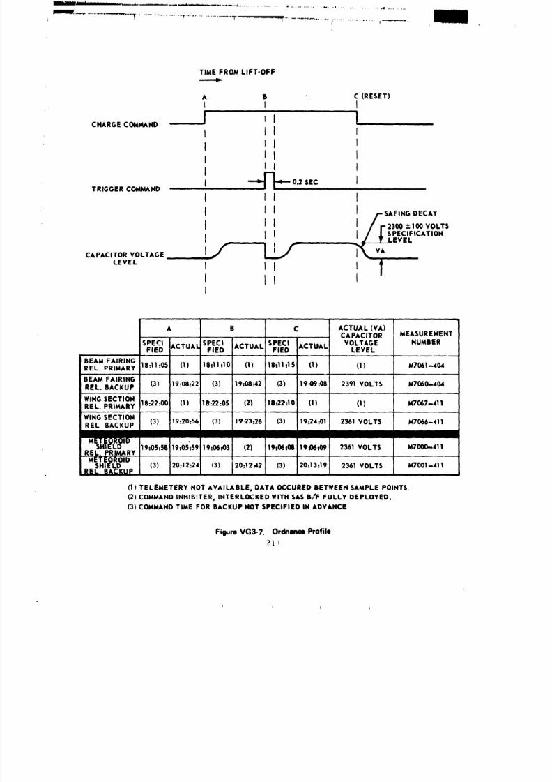
8/8/2019 MSFC Skylab Structures and Mechanical Systems Mission Evaluation
http://slidepdf.com/reader/full/msfc-skylab-structures-and-mechanical-systems-mission-evaluation 231/348
1
TIME FROM LIFT-OFF
A B ' C (RESET)
I I I
CHARGE COMMAND J" I I ' ' 1
I II I
II I
i mla II . --_J J_--0.2SEC
ITRIGGERO_ND
I II I
I II I - SAFINGECAY
I I J J / 2300±100VOLTS
I I j . j ¥/ [SPECIFICATION, . , _,_IF------LE VEL
CAPACITOR VOLTAGE I / L._ I__ VA
LEVEL I II I tt tlI
A B C ACTUAL (VA)MEASUREMENTAPACITOR
SPECI ACTUAL SPECI ACTUAL SPECI ACTUAL VOLTAGE NUMBERFlED FlED FlED LEVEL
BEAMFAIRINGREL PRIMARY 18:11=05 (1) 18=11:!0 (1) 18111.1S (I) (1) M7061-404
IBEAMFAIRINGREL. BACKUP (3) 19:08=22 (3) 19:08:42 (3) 19.4)9..08 2391 VOLTS M7060-.404
WINGSECTIONREL PRIMARY 18=22.00 (!) 18..22=05 (2) 18t27:10 (I) (1) M7007-411
WINGSECTIONREL BACKUP (3) 19:20:56 (3) 19.,23:26 (3) 19..24=01 2361 VOLTS M7066-411
M19=05:5819:05%5919=06..03 (2) 19:06:08 19_06109 2361 VOLTS M7000-.411
RELo PI_IMARY
METEOROIDSHIELD (3) 20:12:24 (3) 20:12_42 (3) 20213:19 2361 VOLTS M7001,411REL. BACKUP
(1) TELEMETERY NOT AVAILABLE, DATA OCCURED BETWEENSAMPLE POINTS.
(2) COMMANDINHIBITER, INTERLOCKED WITH SASB/F FULLY DEPLOYED.
(3) COMMANDTIME FOR BACKUP NOT SPECIFIED IN ADVANCE
Figure VG3-7. Ordnance Profile
_.l;
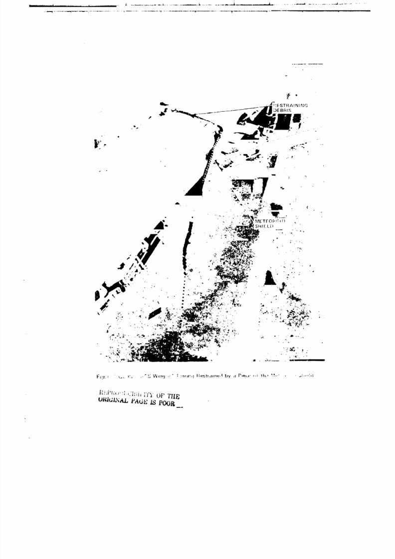
8/8/2019 MSFC Skylab Structures and Mechanical Systems Mission Evaluation
http://slidepdf.com/reader/full/msfc-skylab-structures-and-mechanical-systems-mission-evaluation 232/348
/
l_.!.J'l_, ': Ll'._i_ L'I"YOP I'tlPj

8/8/2019 MSFC Skylab Structures and Mechanical Systems Mission Evaluation
http://slidepdf.com/reader/full/msfc-skylab-structures-and-mechanical-systems-mission-evaluation 233/348
.......................................... El I I
Prior to loss of signal, the solar array system wing #1
fairing secure measurement showed "secure" at the lastground station coverage before the automatt_ switch selector charged
and fired the beam fairing ordnance, When no indication of solar arraysystem wing #i fairing deploy occurred at acquisition of signal, the
backup alrlock module digital con_nand system signal was sent
to charge and flre the backup ordnance. The backup signal for wlng
section ordnance was necessary due to an interlock that prevents the
primary wing section ordnance from firing If the beam fairing has not
fully deployed. The wlng section position indicators showed some
movement but full deployment readings did not occur until after the
beam fairing was freed. The first manned crew deployed the beam fairing
during an extravehicular activity, after breaking the actuator damper_
by exerting the necessary moment ( m 750 ft-lb) with a beam erection
tether attached between the aft end of the beam fairing forward vent
module and the intersection of the deployment assembly and discone
antenna support brace (Figure VG13-4). The vehicle was then
maneuvered to an attitude to allow the three wing section actuator dampers
to be warmed by solar heating. At the end of 5 I/2 hr the wing
sections were fully deployed.
e. Recomendarions.
(i) Instrumentation should be provided to indicate
position or condition of deployment for critical systems.
(2) Consideration should be given to the manual deploy-
ment of solar power systems In the event a malfunction occurs In the
primary mode.
(3) Acoustically actuated vents are good for environmental
protection on the ground and activated by the normal launch environment.
4. Heteoroid Shield. It is not possible to include a mission
evaluation of the meteoroid shield as it was torn off during ascent.
Consequently. since some of the subsystems may be applicable to future
programs, more detalled preflight data are included.
a. Cenera[ requirements. The general requirements for themeteoroid shield are:
(I) Provide protection such that the probability ofn_ pressure loss in the habitation area will meet or exceed a clust,.r
requirement ,f 0.995 for 8 consecutive months. The meteoroid
environment shall be as specifled in NASA THX-53957.
(2) Encompass the cylindrical section of the workshop
and provide closures at each end to cover the annulus when deployed.
216
8/8/2019 MSFC Skylab Structures and Mechanical Systems Mission Evaluation
http://slidepdf.com/reader/full/msfc-skylab-structures-and-mechanical-systems-mission-evaluation 234/348
......_"i
-............................................... ,lildiH I_,1 I !
.
(3) During prelaunch, be no more than 6 in. radially
from the outer surface of the habitatioa tank.
(4) Be free of flutter or other divergent instabilities
during the launch phase.
(S) During orbit, initiate deployment by a signal from
the instrument unit over the instrument unit swltch selector with a
backup deployment command from the alrlock at the workshop/airlock
Interface.
(6) Single point failure shall not inhibit deployment.
b. Subsystem configuration. The original "wet" workshop
concept envisioned a scroll-llke shield, wrapped tightly around the
cylindrical section of the S-IVB L}12 _ank and held together mechanically.
The shield was to be released in orbit, by its own stored energy, so
that it would provide an annulus between shield and LH 2 tank. Later,
the idea of ordnance release was incorporated for the "wet" workshop;
first the S-[VB type "mild detonating fuse", and then the "expandable
tube" which was first used in military programs.
Four basic methods of meteoroid shielding were considered
during the conceptual design of the "wet" workshop: (I) single armor
plate (2) spaced sheet (_) spaced sheet with foam filling, and (4) spaced
sheet with multilayered foam/Mylar filling. Trade studies on these
methods included considerations such as: minimum modifications to the
vehicle, weight, flutter, vibration, purge gas consumption, transportation,
and matching of the shield to the stage (the flight shield had to be
mounted on a propulsion test article for firing at SAC'TO, then removed
and shipped to KSC for mounting on the workshop flight vehicle).
_t is pointed out that the temperature region considered on the "wet"
workshop during boost was from -423 °F on the inside of the tank to
475 °F on the outside. The large amount of helium purge gas required
for a spaced shield filled with insulation to combat these temperature
extremes _de further consideration of this meteoroid shielding concept,
items (3) and (4) above, _mpractlcal. This left only the single armor
plate or thv spaced sh,_et, items (I) and (2) above, as acceptable design
concepts to pursue.
The NASA meteoroid flu:. model required a shield, equal
in protective capability tca single sheet of 2024-T6 aluminum 1.43 cm
thick, in order to obtain the probability of no penetration of 0.995,
but weight was a primary consideration on the "wet works}op." Thus,
using the 1.43-cm single plate thickness as a base, and V.C. Frost's
equations tu obtain equivalent sheet thicknesses at discrete spacings,
a minimu_ distance of "i.5-1n. for a 0.025-In.. thick sheet was cal-
culated. It was felt that, slnc_ the function of the spaced sheet
is to disintegrate meteoroids, and once a meteoroid is disintegrated
its debris spreads into a con!cal shape, _ore sp_Ing would be
advantageous. More spacing would allow the debris to spread further,
217
8/8/2019 MSFC Skylab Structures and Mechanical Systems Mission Evaluation
http://slidepdf.com/reader/full/msfc-skylab-structures-and-mechanical-systems-mission-evaluation 235/348
_.........I I I' ....... T'--'-':-" ' _ _ T ,
thu.,,reducing the forrp per unit area on the tank wall. This was ac-
compllshed by going to a 5-1n. nominal 3paclng. Furthermore, a deployable
shield required no "Z" stiffener frames; only relatively light hardware
was necessary at p_ch end, forward and aft, along the -,_In tunnel,
and alone, the ordnance train. Trade .,_udle- showed t:_at the 0.O25-in.
thick deployabJe shield with a 5-1n. spacing would weigh slightly
over 1,000 Ib, while a fixed shield wlth a spacing of 1.65 its. had
to be 0.045-in. thick and would weigh 1,700 lb. Any spacing further
than 5 in. would increase the weight because of the larger size of
supporting frames, Based on the foregoing, the 0.025-in. thick,
5-in. spacing, deployable _eteorold shield concept was designed -or
the "wet" workshop. When the workshcp was coverted from "wet" to "dry",
only a minimum amount of change was permitted; conceFt wa_ to remain
the same. Additionally, it is pointed out that even tEougb _ot listed
in the CEI speciflcatlon_ the deployable meteoroid shield, with its
thermal protective paint pattern together with the low emissivity goldFapton coa_ing on the habitation tank exterior, provided a natural
radiant heat barrier.
During ground handling and boost, the deployable shield (Figure
VG4-]) was to be held in intimate contact with the habitation area cylinder
wall by clrcumferentlal tension provided by the spring force of 28
titanium frames that were part of the auxiliary tunnel. Following
orbital insertion, the worksLop pressure was to be blowe down and the
solar array system deploye¢1. Then firing of a confined detonating fuse
inside an oval "expandable tube" would Lound the tube and rupture six
tension carrying ordnanc_ straps (Fizure VC4-2) along the length of
the shield. This event would allow eight deployment links each. at
the forward apd aft shield end, driven by the stored energy of preloaded
torsion bars (Figure V(_4-3) and mounted to th _ tan_ skirt flanges, to
deploy the shield in a translatlon/rotatlonal mode (Fig, re VG4-4). The
final shape of the deployed shield was to be a cylinder concentric to,
an¢i spaced at, a nominal distrnce of 5 in. from the l_bltatlon cylinder
wall (Figure VC4-5). The additional shield circumf#rence required
to assume the lar_er diameter was provided by a folding pane" assembly
located under the redundant ordnance assembly (Figure Vq4-6).
['ne shield was assembled from 16 curved, 135-in. radius, 0.025-in. thick,
2014-['6 aluminum prefoza;leJ panels, some of them with ..;mailer panel
inserts to allow use of th,, wardroom window and scientific airlocks
on orbit, one provided access to the ground access panel. The shield
was, by way of butterfly hinges, connected to 12 straps running under the main
ttmnel and Londed to the tank (Figure VG4-7). In the vicinity
of the ordnance assembly, two ends o! the shield overlapped. "[he::weL'e_oined w,th 14 tr_mnlon bolts whlc', were tlghtened for rigging (Figure
V(;4-8). The tension caused by the trunnion bolts together wlth the
spreading of the auxiliary tunnel frames was to provide the hoop tension
required for Intimate contact during bet:st. A series of 0.005 CRES
performed "fingers" were riveted under the forward and aft end of the
shield forming a "hoot" (Figure VC4-9) that would close off the atmulus
218
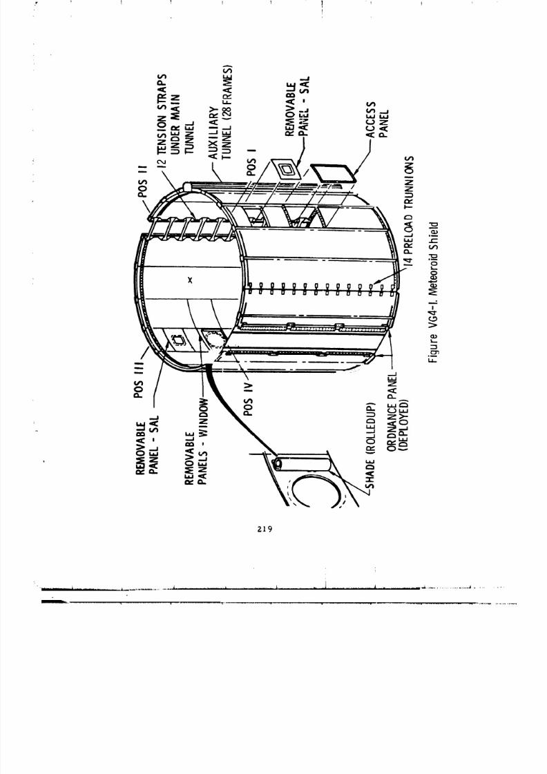
8/8/2019 MSFC Skylab Structures and Mechanical Systems Mission Evaluation
http://slidepdf.com/reader/full/msfc-skylab-structures-and-mechanical-systems-mission-evaluation 236/348
z]9
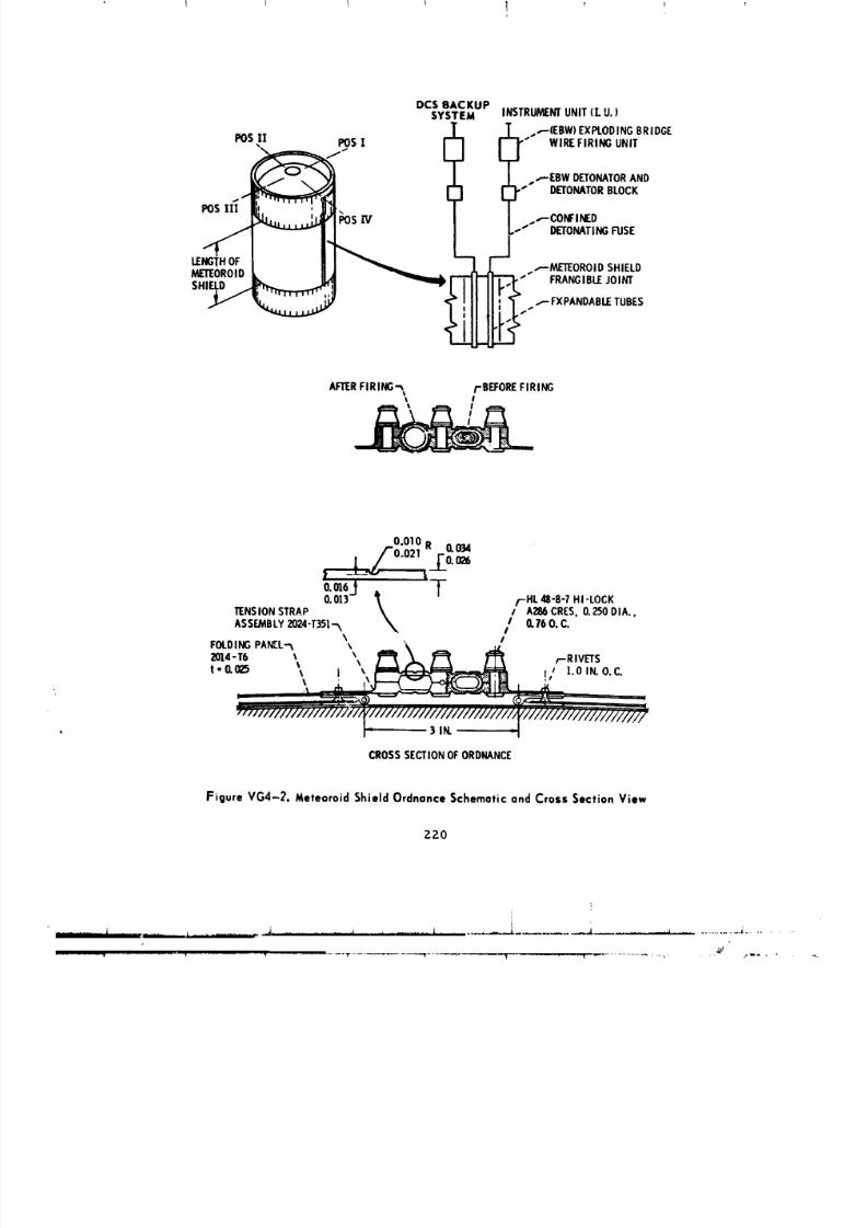
8/8/2019 MSFC Skylab Structures and Mechanical Systems Mission Evaluation
http://slidepdf.com/reader/full/msfc-skylab-structures-and-mechanical-systems-mission-evaluation 237/348
DCSBACKUPSYSTEM INSTRUMENTNIT(LU. )
FOS[| POS! ; "1 __ ,..,-(EBW)EXPLODINGBRIDGE
_i" LJ _,.,__IR:;I;I_NATIIIIND
_[_L_ ?"""-Dc:ONF?TODRBLOCK--'' DETONATINGUSE
_()R(3iD L U _ _ "_""_FRAMETENO_O_ jSoH_I_D
AFTERIRING'-',, FBEFOREIRINGII I
O.010R 0.034
/'ooo21_.[_o.__Li
o,m61 tO.013J /t f-HL 48-8-7HI-LOCK
i AZ86CRES,0.250DIA.,TENSIONSTRAP _ I 0.760.C.ASSEMBLY024-T35].._ _, I
\ IFOLOINGPANCL.-._ \ __\ _ _.W_
2014-T6 _ _ ,,-RIVETS- 0._5 I I_ l.O IN.O.C.
: 3iN. -_
CROSSSECTIONOFORDNANCE
Figure VG4-2. Meteoroid Shield Ordnance Schematic and Crass Section View
Z20
iii
t
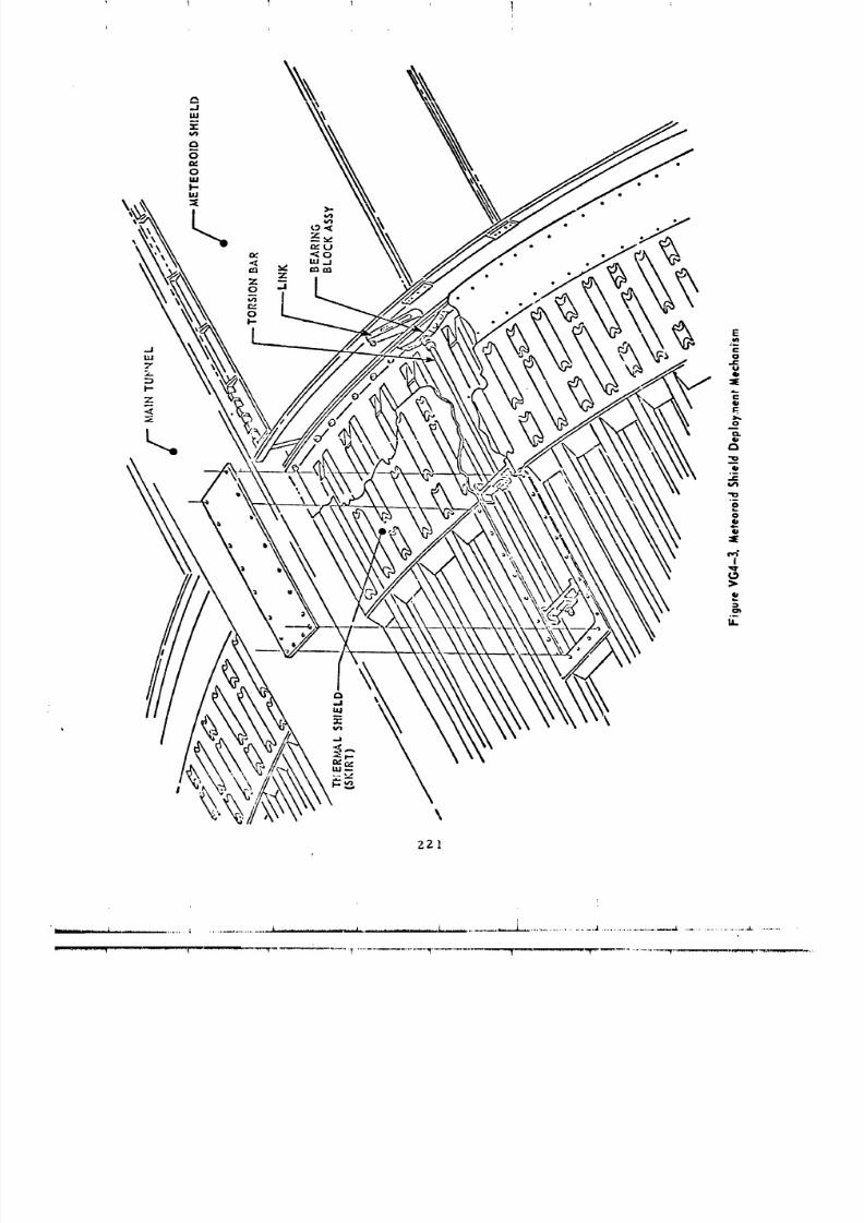
8/8/2019 MSFC Skylab Structures and Mechanical Systems Mission Evaluation
http://slidepdf.com/reader/full/msfc-skylab-structures-and-mechanical-systems-mission-evaluation 238/348
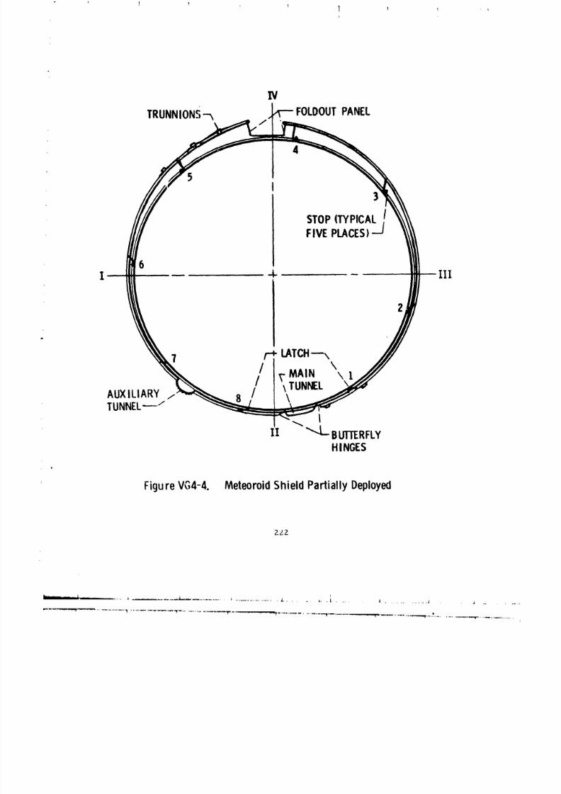
8/8/2019 MSFC Skylab Structures and Mechanical Systems Mission Evaluation
http://slidepdf.com/reader/full/msfc-skylab-structures-and-mechanical-systems-mission-evaluation 239/348
IV
TRUNNIONS--x FOLOOUTANEL
4
5
)
STOPTYPICAL
FIVEPLACES)J
FigureVC,4-4. MeteoroidShieldPartiallyDeployed
2ZZ
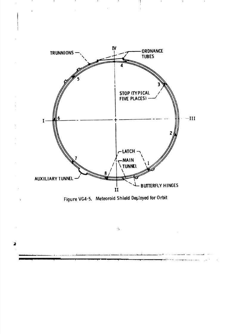
8/8/2019 MSFC Skylab Structures and Mechanical Systems Mission Evaluation
http://slidepdf.com/reader/full/msfc-skylab-structures-and-mechanical-systems-mission-evaluation 240/348
IVTRUNNIONS--, 1 I.-7 ORDNANCE
I 6 + -Ill
2
,--LATCH\
l -MAIN \
/ \ TUNNEl. \ 1\
AUXILIARYTUNNEL'J
_"4- BIJ]'rERFLYINGESII
FigureVG4-5. MeteoroidShieldDeployedorOrbit
%
............ t - - ,...,*.--,.....--.. ,,a.................................... ,,L,....,,,,..-- ..... _ ........ ........--,,.L .................. _ ,,I .......................... L ........................ _. ......
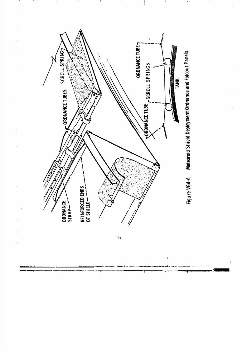
8/8/2019 MSFC Skylab Structures and Mechanical Systems Mission Evaluation
http://slidepdf.com/reader/full/msfc-skylab-structures-and-mechanical-systems-mission-evaluation 241/348
I i I 'I
':',4
i !
r ...................... T............ -_.............T"..............................T.................... "T........... T ............. -_"'-_ "-'-' .................. _.............. , .Jilllli
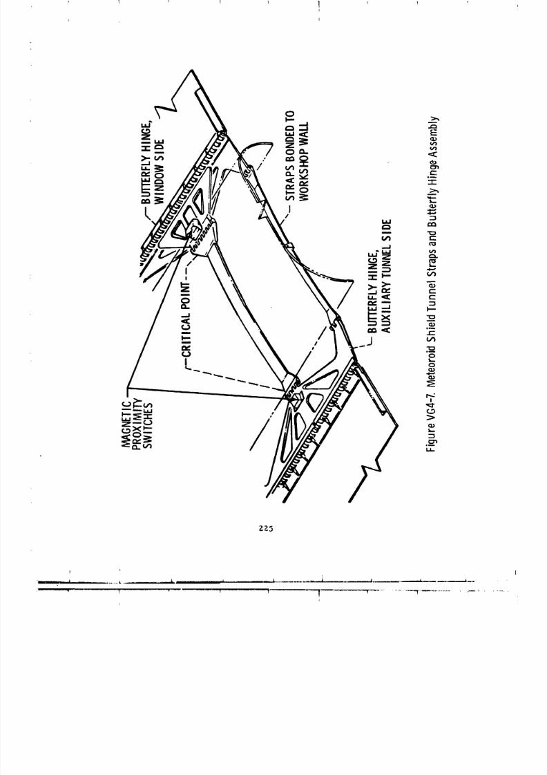
8/8/2019 MSFC Skylab Structures and Mechanical Systems Mission Evaluation
http://slidepdf.com/reader/full/msfc-skylab-structures-and-mechanical-systems-mission-evaluation 242/348
I
ZZ5
'
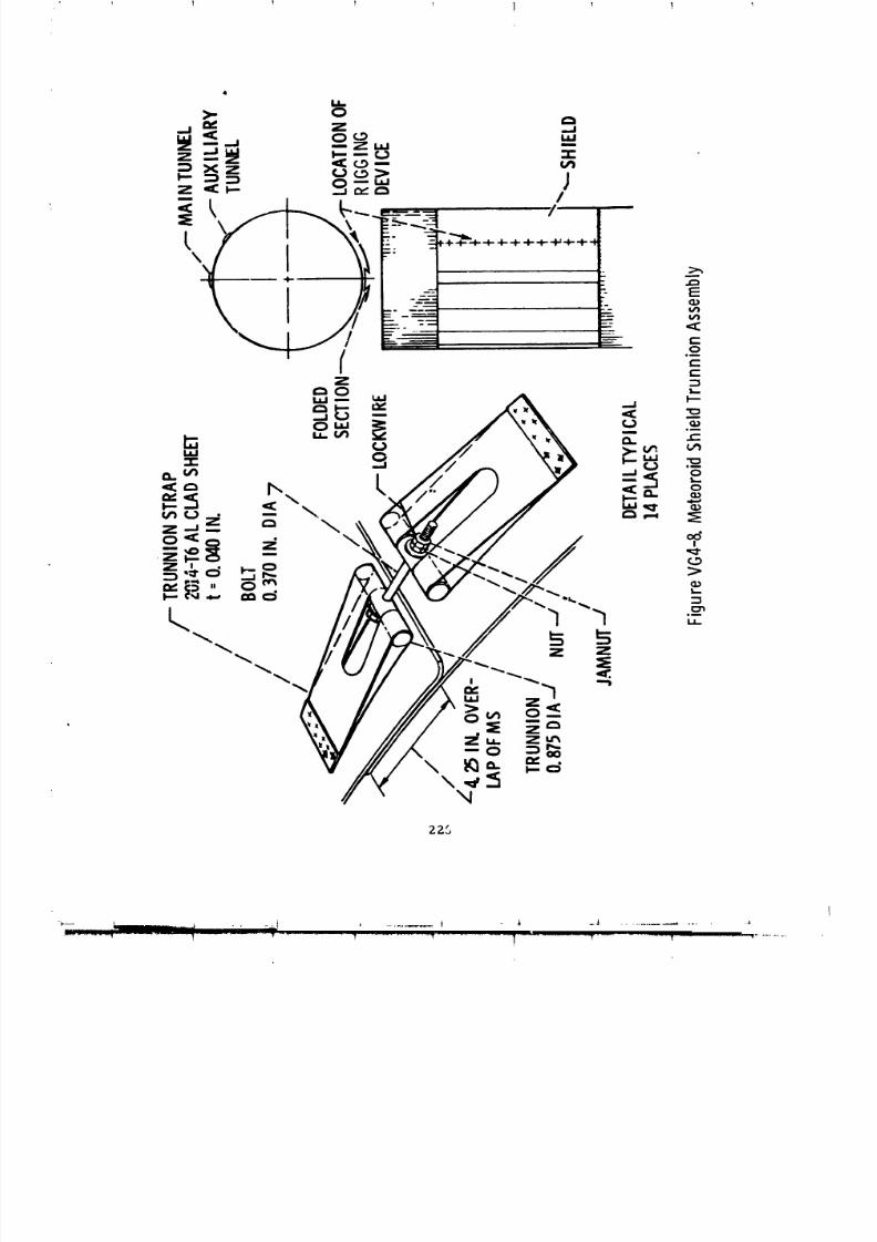
8/8/2019 MSFC Skylab Structures and Mechanical Systems Mission Evaluation
http://slidepdf.com/reader/full/msfc-skylab-structures-and-mechanical-systems-mission-evaluation 243/348
ZZS

8/8/2019 MSFC Skylab Structures and Mechanical Systems Mission Evaluation
http://slidepdf.com/reader/full/msfc-skylab-structures-and-mechanical-systems-mission-evaluation 244/348
I '_ T 1 !
227
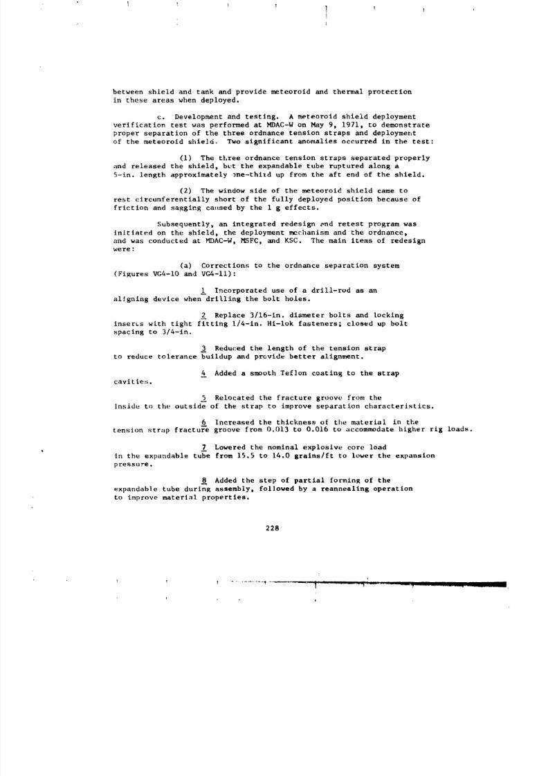
8/8/2019 MSFC Skylab Structures and Mechanical Systems Mission Evaluation
http://slidepdf.com/reader/full/msfc-skylab-structures-and-mechanical-systems-mission-evaluation 245/348
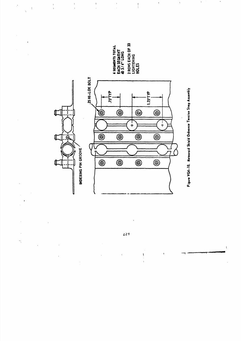
8/8/2019 MSFC Skylab Structures and Mechanical Systems Mission Evaluation
http://slidepdf.com/reader/full/msfc-skylab-structures-and-mechanical-systems-mission-evaluation 246/348
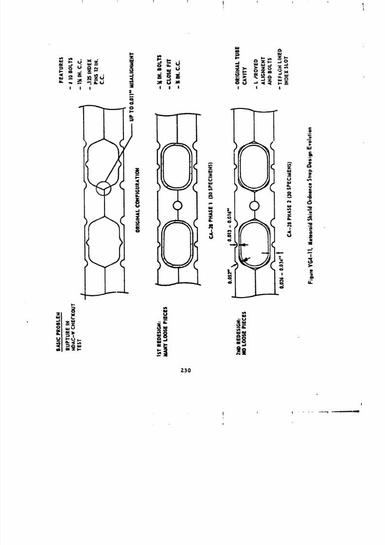
8/8/2019 MSFC Skylab Structures and Mechanical Systems Mission Evaluation
http://slidepdf.com/reader/full/msfc-skylab-structures-and-mechanical-systems-mission-evaluation 247/348
! _ I T Ij
Z30
8/8/2019 MSFC Skylab Structures and Mechanical Systems Mission Evaluation
http://slidepdf.com/reader/full/msfc-skylab-structures-and-mechanical-systems-mission-evaluation 248/348
Added a requirement to I00 percent metallographlc
inspect each deliverable length of expandable tubing, as well as checks
of the tube hollows from which these lengths are drawn.
(b) Corrections to the deployment mechanism
(Figure VG4-12.):
Incorporated latches at the four swing arms
near the main tunnel to prevent shield rebound during deployment
(Figure VG4--12).
Incorporate d redundant strain gages on eachtorsion bar to measure the angular rotatlon/posltion of the shield.
Increased torque of the #i and #8 forward
and aft torsion bats and shortened scum drive slots in the shleld flanges
to achleve more positive drive.
Added torsion springs in all hinge areas to
assist in the deployment.
(c) Corrections to the meteoroid shield:
Incorporated several vertical stiffeners on
the window and ordnance trunnion panel to prevent flutter during boost.
(d) Corrections to test hardware (Figure V_',-13):
Incorporated a counter balance "zero g kit"
for ground deploymen* to mi_limlze gravlt4tlonal effects.
The main items of hardware development and test programs were:
(11 CA-28. Sixty subassemblies, consisting of primary
and secondary 12-1n. long expandable t, hes with 4-in. long straps
were tested to verify the tube ordnanc# charge change from 15.5 gralns/ft
to 14.0 +--0.3 gralns/ft and the redesi_t of the tension straps
to prevent tube rupture. Some tabs (hall metal pieces) along the fracture
groove csme off the tension straps durln$ phase on: of this test program,
Testing was successfully completed in Au6ust 1971.
(2) CA-30. Three subassemblies consisting of primary
and secondary 7-it long tubes with tension straps were test fired,
after acoustic and flight temperature (125, -140 °F ) testlnl, in
order to qualify the redeslsn. Testing was completed successfully 'inApril 1972.
(3) CA-31. Two subassemblies consisting of primary
and secondary full length tube_ (22-it long), tension straps, and
fold-over panels were tesbed ur.der riddled conditions. The tests were
231
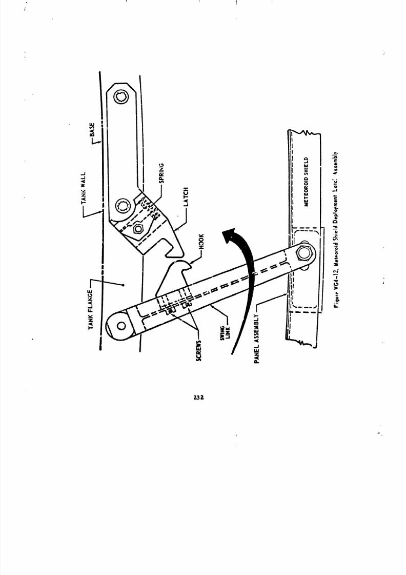
8/8/2019 MSFC Skylab Structures and Mechanical Systems Mission Evaluation
http://slidepdf.com/reader/full/msfc-skylab-structures-and-mechanical-systems-mission-evaluation 249/348
_Z

8/8/2019 MSFC Skylab Structures and Mechanical Systems Mission Evaluation
http://slidepdf.com/reader/full/msfc-skylab-structures-and-mechanical-systems-mission-evaluation 250/348
2_3
i
!
m ..... _ .... • i i ............................ ,Imlm_l j.,L. , ............................ ,_. .. .. .. .. .. .. .. .. .. .. .. .. .. .. .. .. . Ji ...................... .._ ................................. ._ ......
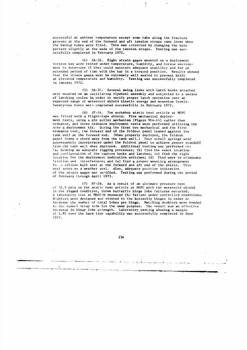
8/8/2019 MSFC Skylab Structures and Mechanical Systems Mission Evaluation
http://slidepdf.com/reader/full/msfc-skylab-structures-and-mechanical-systems-mission-evaluation 251/348
successful at ambient temperature except some tabs a]ong the fracture
grooves at the end of the forward and aft tension straps came loose when
the backup tubes were fired. This was corrected by changing the hole
pattern slightly at the ends of the tension straps. Testing was suc-cessfully completed in February 1972.
(4) CA-32. Eight strain gages mounted on a deployment
torsion bar were tested under temperature, humidity, and torque environ-
ment to deter,nine if they could maintain adequate stability and for an
extended period of time with the bar in a torqued position. Results showed
that the strain gaRes must be extremely well sealed to prevent drift
at elevated temperature and humidity, Testing was successfully completed
in January 1972.
(5) CA-3L. Several swing links with latch hooks attached
were mounted on an oscillating flywheel assembly and subjected to a series
of latching cycles in order to verify proper latch operation over an
expected range of meteoroid shield kinetic energy and momentum levels.Twenty-one tests were completed successfully in February 1972.
(6) ST-14. The workshop static test article at MSFC
was fitted with a flight-type shield. Five mechanical deploy-
ment tests, usin B a pin puller mechanism (Figure VG4-1_) rather than
ordnance, and three ordnance deployment tests were performed utilizing the
zero g deployment kit. During the first two mechanical and the first
ordnance test, the forward end of the foldout panel leaned against the
tank wall at the forward end. (When properly deployed, the foldout
panel forms a chord away from the tank wall.) Four scroll springs were
subsequently incorporated under the foldout panel to achieve proper standoff
from the tank wa_l when deployed. Additional testing was performed to:
Ca# develop an adequate rigging procedure; (b) find the exact location
and eonfiRuration of the capture hooks and latches; (c) find the right
1oc:ation for the deployment indication switches; (d) find ways to eliminate
friction and tnterference; and (e) find a proper mounting arrangement
fo, a silicon bulb seal at the forward and aft end of the shield. This
seal acted as a weather seal. Also, adequate position indication
of the strain Rages was verified. Testing was performed during the period
of February through April 1973.
(7) ST-28. As a result of an ultimate pressure test
of 32.5 psi_ on the static test article at _SFC with the meteoroid shield
in the rigged condition, three butterfly hinge lobe failures occurred.
A laboratory test at MDAC-W repeated the failure under controlled conditions.
Doublers were desiRned and riveted to the butterfly hinges in order tc
Inc'rease the number of total lobes per hinge. Matching doublers were bonded
to the tunn_,1 strap side for the same purpose. The result w_s an effective
Inc'rease in hinge lobe strength. Laboratory testing showing a margin
of 1.81 over the base llne capabl]ity was successfully completed in June
1972.
234
...... _.........................................................................................._.............................................................................................. , .........
I
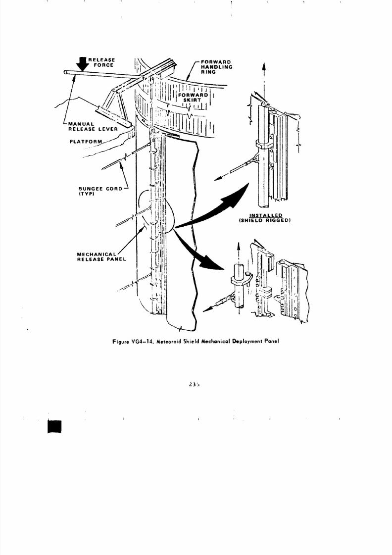
8/8/2019 MSFC Skylab Structures and Mechanical Systems Mission Evaluation
http://slidepdf.com/reader/full/msfc-skylab-structures-and-mechanical-systems-mission-evaluation 252/348
] ! 1
RELEASE FORWARD
FORCE R._INGHANDLING !
_T_---FORWARD ] I OsxI.T 1 I"
RELEASE LEVER
PLATFOR.... __
8UNGEE CORD(TYP)
INSTALLED(SHIELD RIGGED)
,Figure VG4-14. Meteoroid Shield Mechanical Deployment Panel
,?.3b
8/8/2019 MSFC Skylab Structures and Mechanical Systems Mission Evaluation
http://slidepdf.com/reader/full/msfc-skylab-structures-and-mechanical-systems-mission-evaluation 253/348
(8) ST-38. During subsequent ultimate pressure testing
to 31 psig on the structural test article at MSFC, strain gage measurements
indicated that the #5 bonded tunnel strap doubler debonded between 28
and 30 psig. Inspection indicated _hat most other bonded doublers had
partially debonded. An =ctual structural failure of the whole butterfly
hinge/tunnel strap system had not occurred. Six control specimens, three
specimens representing current bonding techniques and three specimens
having controlled unbonded areast were tested in the laboratory. An
additional three specimens having a 50 percent bond defect, a i00 percent
unbonded area, and a i00 percent unbonded area with a 4-1ayer resin-flber glass
"band-aid" fix were tested at MDAC-W. Test results demonstrated that
the partially unbonded doubler and the "band-aid" fix provided a substantial
margin above the required functional loads. An inspection was performed
on the workshop at KSC. Some small partial debonds were detected but a fix
was not deemed necessary.
As part of the KSC workshop rigging and checkout procedure
K0-3018, performance of a mechanical deployment test using a pin puller
mechanism rather than ordnance was required during October 1972 in order
to verify the integrity of the redesigned shield and its components on
the flight article. The shield was semlrlgged for transportation from
Huntington Beach to KSC, i.e., the torque rods were slightly torqued
in reverse direction to provide slight pressure of the shield against
the tank. However, during the rigging for transporat!on, one torque
rod was overtorqued because the bracket for the torque rod keeper was
installed backwards. Also, one torque rod was sheared off because
of torquing in the reversed direction. The flight item was reworked
to correct these discrepancies. During the mechanical deployment
checkout at KSC, the two capture latches on the window side of the shield
did not engage. A subsequent failure investigation showed the following
discrepancies:
(i) A thermoco_Lple wire bundle running from the shield
over the butterfly hinge line into the systems tunnel was too taut
when the butterfly hinge folded.
(2) The capture hooks were not properly shinnued to their
required position.
(3) The forward bulb seal caused too much friction against
the swing links. This was mainly due to the whole shield being mounted
0.15 in. too far forward (above maximum tolerance). The tunnel straps were
not properly adjusted during bonding at Huntington Beach. This required
both of the 22-ft long butterfly hinges to be cut approximately in half.
236
, , i
I | 1 j
8/8/2019 MSFC Skylab Structures and Mechanical Systems Mission Evaluation
http://slidepdf.com/reader/full/msfc-skylab-structures-and-mechanical-systems-mission-evaluation 254/348
8/8/2019 MSFC Skylab Structures and Mechanical Systems Mission Evaluation
http://slidepdf.com/reader/full/msfc-skylab-structures-and-mechanical-systems-mission-evaluation 255/348
1 ! ; 1 I
q
The data also show traces indicating charge fire and safing
(Figure VG3-7). Since the ordnance train was no longer present this is
only an indication that the primary and backup firing mechanisms andelectrical bridge wires were still functional.
Although the meteoroid shield dld not survive the launch environment,
its loss did not drastically affect the probability of crew safety with
regard to meteoroid penetration. The probability of crew safety for the
longest planned manned segment of 56 days was 0.9999998 without the
meteoroid shield. This is based on the crew having less than 4 min
to evacuate before the pressure dropped to 3.6 psia. The probability
of a meteoroid not causing leakage of inter_al pressure for the workshoo
was reduced for the various mission times _.sshown below:
28 Days 56 Days 240 Days
With Meteoroid Shield 0.999+ 0.999 0.995
Without Meteoroid Shield 0.995 0.990 0.958
These probability values applied at the start of the time segment
and represented the projected success expected for the tlme segment.
During the 8 months of the Skylab misslon t no penetration was noticed
or reported and no habitation area pressure loss was recorded.
e. Conclusions. Given the requirement for meteoroid protection
on a new Saturn V type vehicle, no additional protection (Justified
on the basis of mathematical analysis and present experience togetherwith habitation tank wall thermal coatings) or a rigidly mounted shield
would be selected. Large and thin sheet metal structures with minimum
support are extremely difficult to handle. Also, adequate tolerance
provisions must be made as the material deforms easily. The venting
of thin overlapping structures must be properly considered when exposed
to rapidly changlnR pressure environments to prevent buckling or rupture.
The expandable tube separation system concept, when properly
designed (in regard to explosive grain size, tube wall preparation,
and tension straps), provides a clean and excellent mode of _eparation
and is well suited for structural separations where contamil tion is
an important factor.
Torque rods, properly designed and utilized, are a good way
of storing deployment energy over an extended period of time withoutrelaxation effects.
238J
8/8/2019 MSFC Skylab Structures and Mechanical Systems Mission Evaluation
http://slidepdf.com/reader/full/msfc-skylab-structures-and-mechanical-systems-mission-evaluation 256/348
5. Workshop Entry Hatch.
a. General requirements for workshop hatch operation and
function are:
(i) Withstand workshop launch and ascent pressure; leakage
to airlock shall not exceed 1.90 ib/hr with airlock at a pressure of
0.5 to 14 psia.
(2) Check valves shall ensure that airlock pressure
not be more than 1.0 psi greater than workshop pressure.
(3) Leakage during extravehicular activity shall be
26 sccs maximum.
(4) Handle operating force shall be no more than 25 lb.
(5) Be capable of 20 functional cycles minimum.
6. Mission performance. The performance of the hatch during
the Skylab mission, with regard to the above requirements, is difficult to
assess since no actual measuring devices were directly associated wltb
the hatch. It is pointed out that several qualification tests were performed
and the results are shown in the following paragraphs. During the launch
and ascent phase, the hatch performed as designed with no excessive leakage.
When the entry hatch was used as the aft airlock extravehicular hatch, no
leakage was detected. During the debriefings, the crew stated that the
handle loads for each of the nine extravehicular activities were
not excessive.
The nine extravehicular activities during the three manned phases
constitute the total cyclin_ (open-close) imposed on the hatch. The hatch
was left open for the unmanned storage periods between the three manned phases
and was also left open at final deactivation.
c. Anomalies. ,3urlng initial pressurization cycles of the
workshop during the first unmanned period, the alrlock/docklng adapter was
being prematurely pressurized by some unknown leakage source
from the workshop. Normally, the workshop should be pressurized
to 5 psi folloued by equalization of the alrlock/docking adapter
pressure. However, the airlock/docklng adapter was being simultaneously
pressurized with the workshop, but was lagging the workshop pressure
by approximately 0.2 to 0.3 psi, until the pressure reached 5 psi at which
time the airlock/docking adapter/workshop pressure then equalized.
Althou_h thls leakage was of no great concern during the initial pres-
surization, it was a consideration for extravehicular activity
operations because at that time the hatch was used as the aft
closure of the alrlock. Therefore, if the leakage was determined
to be through the hatch seals or check valves, it could be of
239
J _ i j _ J l J
8/8/2019 MSFC Skylab Structures and Mechanical Systems Mission Evaluation
http://slidepdf.com/reader/full/msfc-skylab-structures-and-mechanical-systems-mission-evaluation 257/348
! I 1 T T I ,
considerable consequence. The check valves were suspect since they
were opened during initial workshop blowdown. As a precaution
that they might be leaking, the first manned crew devised makeshift
"flapper valves" from onboard materials (mosite and tape) which
they applied to the workshop side of the entry hatch'check
valves when the hatch was closed. It is doubtful that the flapper
valves were ever effective. The nine subsequent Skylab extravehicula_
activities were performed with no leakage reported. Several possibilities
exist for the source of the pressurization leak: (i) Dirt or some foreign
material did not allow the check valves to seat, causing the leakage.
The foreign material could have become dislodged when the hatch was initially
opened; (2) The hatch seal could have leaked, however, inspection by
tile first manned crew indicated that it was smooth, uniform and in good
shape. Test data concern:.ng leakage of the hatch and check valves
show that the requirements listed in paragraph a. were not exceeded.
The test results are:
(i) Access Hatch Qualification Test Report MDC G3363 Pro-
duction acceptance test on the qualification hatch at 10.5 psig with helium
gas (no check valves on hatch): leakage was 0.51 sccs. Pressure cycle
test and subsequent leakage at 10.5 psig with helium gas: leakage was0.68 sccs.
T_ previbration leak tests were made at 10.5 psig.
Leakage was 1.87 and 2.45 sccs. A post-vibration leak test showed
the leakage to be 1.96 sccs.
(2) Access Hatch Repeat Cycle Qualification Test Report
MDC G3379. Leakage at 5 pslg after 0,25,50,75, and i00 cycles of opening
and closing the hatch was 1.20, 0.50, 1.30, 1.00, and 0 scims, respectively.
(3) Access Hatch Check Valve Qualification Test Report MDC
G3375. Prev!bratlon leak test at i.3 psig with GHe in the check direction:
leakage was 6.10 sclms. At 26 psig the leakage was 1.71 sclms. The test
requirement for the previbration leak test of tbe hatch check valve
was for not more than 350 scims. Post-vlbratlon leak test of the valve
at 26 pslR with CHe in the check direction: leakage was 17.70 scims. At
20, 15, and 8.3 pslg the leakage tares were 14, 9.46, and 5.50 scims,
respectively.
The test results show that the leakage of the test
hardware was less than the leakage rate allowed by the requirements.
Therefore, if the pressurization leakasa problem was
through the hatch, the aforementioned speculation of foreign material inthe valve seat area would be the most logical explanation.
d. Reco,_endatlons. Use of check valves to control pressure
should be exercised with cautlon. Check valves are potential leak sources
and should be considered as such.
240
'11111I _ " " _ .... 1 ............. l .............. , dk,,_ _' ...... _ -- --_ 1",, ....... A ............................... . | ,,,
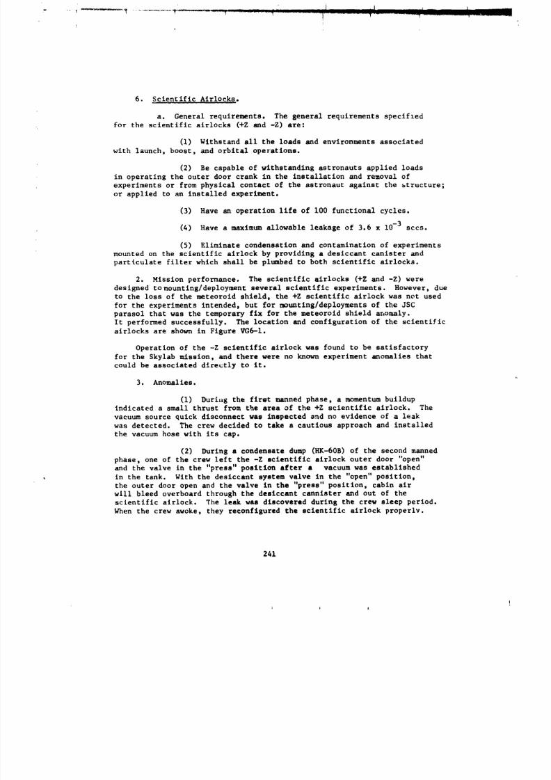
8/8/2019 MSFC Skylab Structures and Mechanical Systems Mission Evaluation
http://slidepdf.com/reader/full/msfc-skylab-structures-and-mechanical-systems-mission-evaluation 258/348
6. Scientific Airlocks.
a. General requirements. The general requirements speclfledfor the scientific alrlocks (+Z and -Z) are:
(i) Withstand all the loads and environments associated
with launch, boost, and orbital operations.
(2) Be capable of withstanding astronauts applied loads
in operating the outer door crank in the installation and removal of
experiments or from physical contact of the astronaut against the structure;
or applied to an installed experiment.
(3) Have an operation life of i00 functional cycles.
(4) Have a maximum allowable leakage of 3.6 x 10⁻³ sccs.
(5) Eliminate condensation and contamination of experiments
mounted on the scientific alrlock by providing a desiccant canister and
particulate filter which shall be plumbed to both scientific airlocks.
2. Mission performance. The scientific airlocks (+Z and -Z) were
designed tomounting/deployment several scientific experiments. However, due
to the loss of the meteoroid shield, the +Z scientific airlock was not used
for the experiments intended, but for mounting/deployments of the JSC
parasol that was the temporary fix for the meteoroid shield anomaly.
It performed successfully. The location and configuration of the scientific
alrlocks are shown in Figure VG6-1.
Operation of the -Z scientific airlock was found to be satisfactory
for the Skylab mission, and there were no known experiment anomalies that
could be associated directly to it.
3. Anomalies.
(i) Duria_ the first manned phase, a momentum buildup
indicated a small thrust from the area of the +Z scientific airlock. The
vacuum source quick disconnect was inspected snd no evidence of a leak
was detected. The crew decided to take a cautious approach and installed
the vacuum hose with its cap.
(2) During a condensate dump (HK-60B) of the second manned
phase, one of the crew left the -Z scientific airlock outer door "open"
and the valve in the "press" position after a vacuum was establishedin the tank. With the desiccant system valve in the "open" position,
the outer door open and the valve in the "press" position, cabin air
will bleed overboard through the desiccant cannister and out of the
scientific alrlock. The leak was discovered during the crew sleep period.
When the crew awoke, they reconflgured the scientific airlock properly.
241
i i i
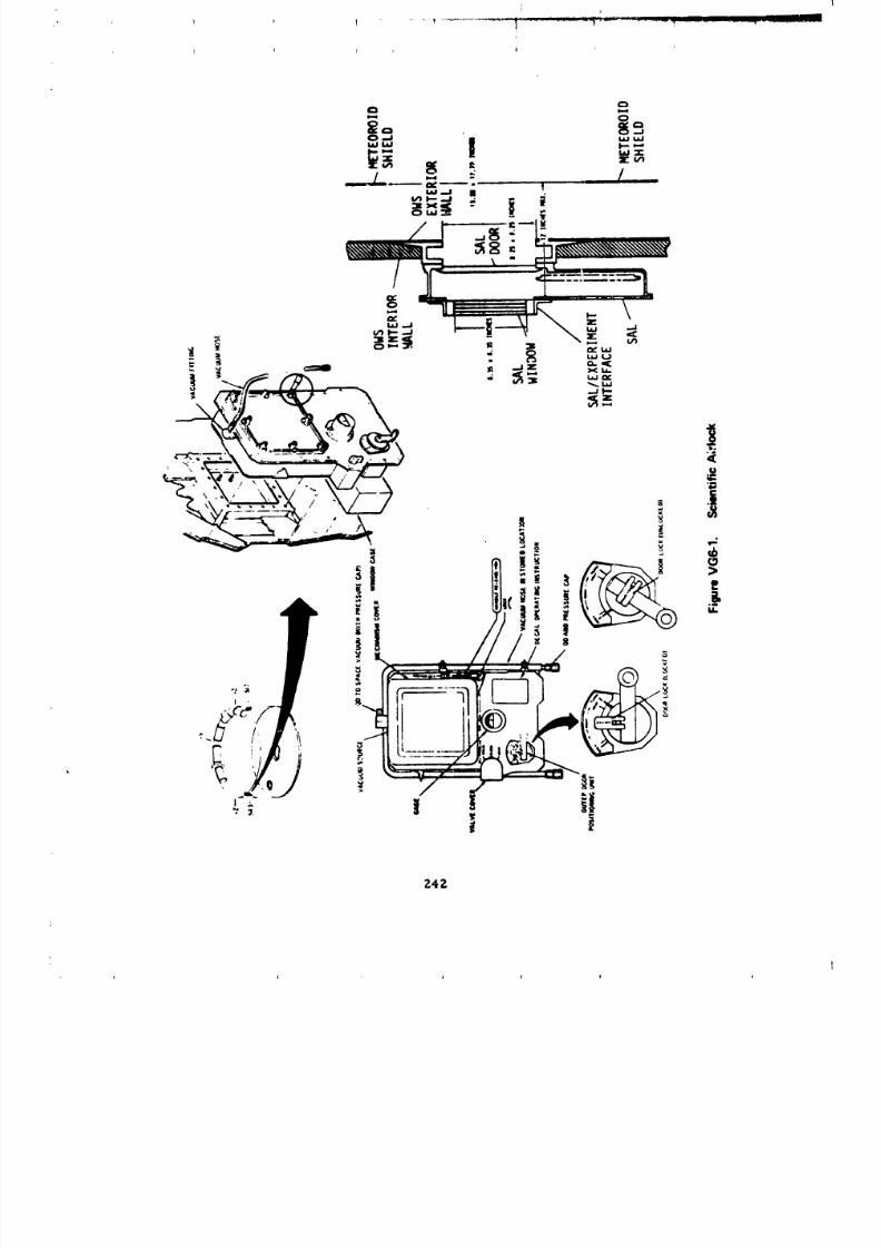
8/8/2019 MSFC Skylab Structures and Mechanical Systems Mission Evaluation
http://slidepdf.com/reader/full/msfc-skylab-structures-and-mechanical-systems-mission-evaluation 259/348
242
8/8/2019 MSFC Skylab Structures and Mechanical Systems Mission Evaluation
http://slidepdf.com/reader/full/msfc-skylab-structures-and-mechanical-systems-mission-evaluation 260/348
(3) During a wardroom window evacuation (HK-84K), during
the first manned phase, the wardroom window cavity was back-filled
with desiccated cabin air. The commander expressed concern for the experiment
which used the scientific alrlock because the desiccant system did not
"appear" co remove the moisture and the "cold" experiments could be
exposed to gas of a questionable moisture quantity. This concern was,
to a large degree, based on the exposure time of the desiccant (about
IO hr).
However, an analysis indicated that the desiccant cannister
was not saturated. This analysis used the manufacturers delivered
condition, predelivery testing, and onboard use to compare unit capacity.
The analysis is supported by the crew observation that the fogging in
the wardroom window appeared to be emitting from the port oppositethe desiccant supply port which_ould indicat_ a leak from the cabin.
It was decided not to actually measure the quality since special equipment
would have to be flown up for any accurate evaluation.
d. Reco_nendatlons.
(i) The =few suggested the pressure gage indicator and
face be more visible because reading the pressure required a pen light.
(2) Although evacuation and repressurization times were
in accordance with those specified, the crew felt larger lines should
be used. This would reduce the unproductive crew time associated with
the scientific airlock evacuation and repressurization,
7. Trash Airlock.
a. General Requirements for the trash airlock are:
(I) The Trash Airlock shall be designed to perform
nominalty in a 5 +0.2 psia external, and 0 to 5.2 pnia internal at ambient
temperatures.
(2) Its service life shall be 1500 complete
functional cycles.
(3) The proof pressure shall be I0 psld and shall
he capable of withstanding a malfunction pressure (either burst or
crushing) of 26 psid.
b, Mission performance. The only instrumentation on the
trash airlock is the absolute pressure gage. Baaed on crew comments
243
J i j ,
8/8/2019 MSFC Skylab Structures and Mechanical Systems Mission Evaluation
http://slidepdf.com/reader/full/msfc-skylab-structures-and-mechanical-systems-mission-evaluation 261/348
i
and subjective evaluation, the trash airlock met or exceeded the structural,
life, and function design requirements. It was cycled 656 times with nomechanical malfunctions. There were several operational difficulties
that were successfully resolved, Twc incidents of near Jaming _ere
attributed to overfilled trash bags. Further problems were avoided by better
control of trash combinations duzing disposal. It was noted during
the first manned phase that the valve handle was inadvertently kicked
or left in an intermediate position, between PRESS and VENT, which
caused a cabin atmosphere leakage of about 3.8 Ib/hr. T11is problem
was overcome by strapping the handle in the PRESS position between operations.
During the second manned phase, an operating characteristic of
the trash airlock was highlighted. The force required to squeeze the lid
during the initial portion of the latchin8 operation was high. It was
found that the high latching force could be overcome by technique or use
of two crewmen.
c. Anomalies. On mission day 41 of the second manned phase, the
crew reported the interlock push rod between the valve handle and the inner
door latch (Figure VGT-I) was bent. The bent rod did not affect
the operation of the alrlock. Bendln s of the rod could have occurred
if the door latch was operated when the valve handle was not in the pressurize
position. Investigation of video tape on the trash alrlock Indicated
that sufficient interlock operation remained to prevent placement of the
valve/outer door handle in the vent position when _he lid lock was not
enraged.
d. Recommendations. Two improvements are recommended for
future use:
(1) A means to positively maintain the valve handle
in the PRESS or VENT position should be added to the handle,
(Z) The squeeze force durin 8 the latching operation shouldbe reduced,
244
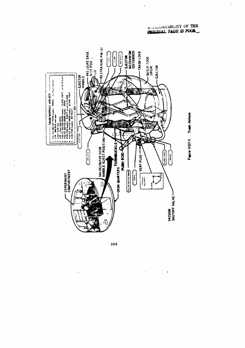
8/8/2019 MSFC Skylab Structures and Mechanical Systems Mission Evaluation
http://slidepdf.com/reader/full/msfc-skylab-structures-and-mechanical-systems-mission-evaluation 262/348
8/8/2019 MSFC Skylab Structures and Mechanical Systems Mission Evaluation
http://slidepdf.com/reader/full/msfc-skylab-structures-and-mechanical-systems-mission-evaluation 263/348
8. Thermal Shield• The MSFC Skylab thermal shield was developed
to be deployed durlnR extravehicular activity over the sunslde of the workshop.It would serve as a shield replacln s the original thermal/meteoroid shleld
that was lost _urlng the first launch phase.
a. Candidate designs. Several candidate designs as well
as material types were evaluated. Among them were:
(i) Stretching a shield over the exposed outer skin of
_he workshop and by the use of hook-type bun_ es attaching the sheet
to the corrugation on the workshop outer cover. This idea was discarded
because of potential problems of extravehicular activity translation
and the possibility of a crewman being entangl_J in the sheet.
(2) Constructing a shield made Irom an inflatable Tedlar
tube and hanging it over the side of the workshop. Potential maintenanceproblems eliminated this.
(3) Various methods of attaching clotheslines to tubular
booms and pulling a thermal shield down the side of the workshop from
a position in the fixed airlock shroud.
(4) Attaching clothesllnes to the bottom of the workshop
with clips while conducting a standup extravehicular activity ztom the
command module and deploying the shield from the fixed airlock shroudarea.
From the two remaining possibilities above, the idea of aslng
a tubular "A-frame" boom with attaching clotheslines came about. The"A-frame" boom would be secured from a position on the telescope mount
outrigger. From here the thermal shield could be attached to the clothesli_e
and subsequently deployed over the sun side of thc workshop (Figure VGg-I).
b. Components. The MSFC thermal shield assembly consisted
of the following components:
(I) TWO deployment poles (Figure VG8-2): Each pole is
assembled from II lengths of l-ln.-diam aluminum tubing, 4.7-it
long. A 3/4-1n.-dlam rod (guide pin) protrudes from one end of
cacl tube, the other end of each tube is slotted to provide the means
of fa_ten'ng _he poles together. A sleeve installs over the slot to
increase the strength of the Joint. The i_terchangeable poles are joined
by insertinR the guide pin of a rod end into the slot of a sleeve end
and twisting the poles. A locknut, located on the rod, is screwed down
against the sleeve and an O-rlng is roiled into position behind the nut
to prevent loosening.
246
A
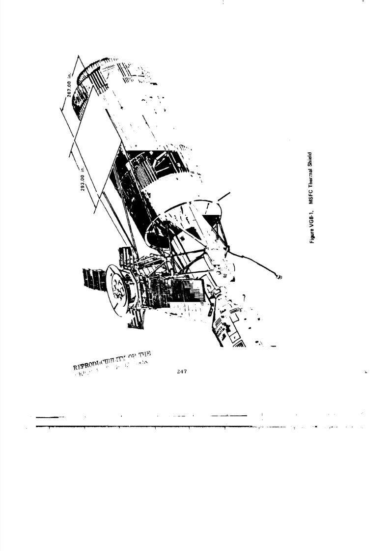
8/8/2019 MSFC Skylab Structures and Mechanical Systems Mission Evaluation
http://slidepdf.com/reader/full/msfc-skylab-structures-and-mechanical-systems-mission-evaluation 264/348
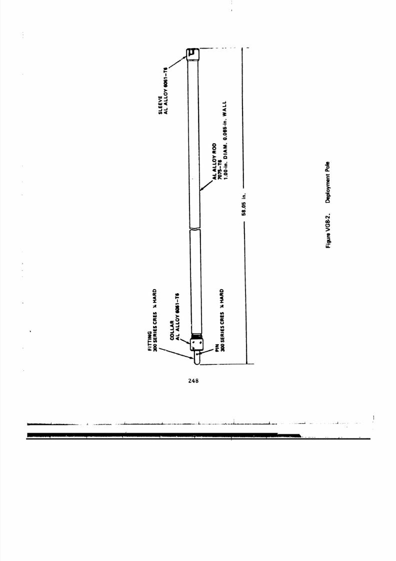
8/8/2019 MSFC Skylab Structures and Mechanical Systems Mission Evaluation
http://slidepdf.com/reader/full/msfc-skylab-structures-and-mechanical-systems-mission-evaluation 265/348
248
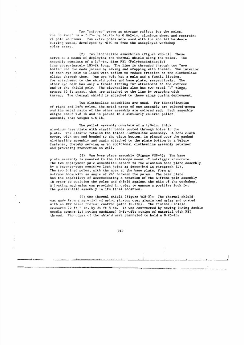
8/8/2019 MSFC Skylab Structures and Mechanical Systems Mission Evaluation
http://slidepdf.com/reader/full/msfc-skylab-structures-and-mechanical-systems-mission-evaluation 266/348
Two "quivers" serve as storage pallets for the poles.
Yhe "quiver" is a 7.75- by 62.75- by 0.062-in. aluminum sheet and restrains
24 pole sections. Two extra poles were used with the special hardware
cutting tools, developed by MSFC to free the undeployed workshop
solar array.
(2) Two clothesline assemblies (Figure VGS-3): These
serve as a means of deploying the thermal shield along the poles. The
assembly consists of a i/4-in, diam PBI (Polybenzimidazole)
line approximately 105-ft long. The llne is threaded through two "eye
bolts" and the ends joined by sewing and wrapping with thread. The interior
of each eye bolt is lined with teflon to reduce friction as the clothesline
slides through them. One eye bolt has a male and a female fitting,
for attachment to the shield poles and base plate, respectively. The
other eye bolt has only a female fitting for attachment to the extreme
end of the shield pole. The clothesline also has two steel "D" rings,
spaced 25 ft apart, that ,ire attached to the line by wrapping with
thread. The thermal shield is attached to these rings during deployment.
Two clothesline assemblies are used. For identification
of right and left poles, the metal parts of one assembly are coloredgreen
and the metal parts of the other assembly are colored red. Each assembly
weighs about 5.8 ib and is packed in a similarly colored pallet
assembly that weighs 4.6 lb.
The pallet assembly consists of a i/8-in, thick
aluminum base plate with elastic bands routed through holes in the
plate. The elastic retains the folded clothesline assembly. A beta cloth
cover, with one end bonded to the plate bottom, is placed over the packed
clothesline assembly and again attached to the plate bottom by a Velcro
fastener, thereby servin_ as an additional clothesline assembly retainer
and providing protection as well.
(3) One base plate assembly (Figure VGS-4): The base
plate assembly is mounted to the telescope mount +Y outrigger structure.
The two deployment pole assemblies attach to the a]uminum base plate assembly
by a bayonet-type positive lock Joint as described in paragraph (!).
The two joined poles, with the apex at the base plate, form an
A-frame boom with an angle of 24° between the poles. The base plate
has the capability of acco_nodatlng a rotation of the A-frame pole assembly
in order to position the poles and shield against the skin of the workshop.
A ]ocklng mechanisn_ was provided in order to ensure a positive lock for
the pole/shield assembly in its final location.
(4) One thermal shield (Figure VGS-5): The thermal shield
was made from a material of nylon ripstop over aluminized mylar and coated
with an RTV based thermal control paint (S-13G). The finished shield
measured 22 ft 3 in. by 24 ft 5 in. It was contructed by sewing (using double
needle commer_'ia] sewing machines) 3-ft-wi_e strips of material with PBI
thread. ]'he edges of the shield were channeled to hold a 0.25-in.
249
--_ ,--_...................-.--...--........_......................................- _.L................................. _ ....... _ .............................
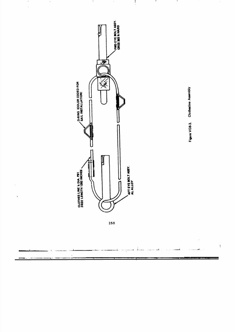
8/8/2019 MSFC Skylab Structures and Mechanical Systems Mission Evaluation
http://slidepdf.com/reader/full/msfc-skylab-structures-and-mechanical-systems-mission-evaluation 267/348
T I I !I
25O
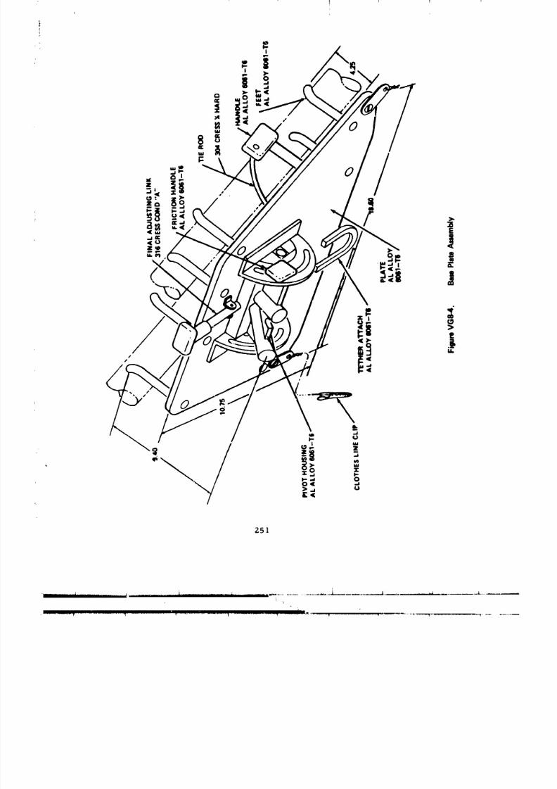
8/8/2019 MSFC Skylab Structures and Mechanical Systems Mission Evaluation
http://slidepdf.com/reader/full/msfc-skylab-structures-and-mechanical-systems-mission-evaluation 268/348
Z51
. liT I I . l l ] I . L . i _ . _ . i .

8/8/2019 MSFC Skylab Structures and Mechanical Systems Mission Evaluation
http://slidepdf.com/reader/full/msfc-skylab-structures-and-mechanical-systems-mission-evaluation 269/348
m
°i!
ZSZ
j J J i 1
I
8/8/2019 MSFC Skylab Structures and Mechanical Systems Mission Evaluation
http://slidepdf.com/reader/full/msfc-skylab-structures-and-mechanical-systems-mission-evaluation 270/348
diam teflon coated beta glass rope. Six grommets were sewn into
the corners and edges for attaching PBI strapping. In the top two
corners of the shield, a 1-in. wide by 0.16-in. thick webbing
approximately 41 ft long was attached. The other ends of eachof these straps were attached, at shield deployment, to the +Z and -Z
outrigger structure, respectively. This allowed the shield
corners to be stretched out. At the four other grommet locations, hooks
were attached. These hcoks were attached to the clothesline "D" rings
at qhield deployment. To ensure that the correct side of thermal shield
was facing the sun, all hooks, straps, and corners were color coded, red
and green, to match the color code of the clothesline assemblies.
The shield was folded for flight using an accordian
fold t_, prevent air pockets in the package and also for ease of deployment.
The folded shield with straps and buckles was packaged in a 14- by 14-
by l]-in, beta cloth and Velcro zippered bag. Located on the outside base
of the ba_ is a tether hook that is used to tether the bag to the base
plate assembly.
(5) One foot restraint plate assembly (Figure VG8-6):
The foot restraint plate assembly was developed to restrain the astronaut
while at the thermal shield deployment work station located at the telescope
mount. This assembly was composed of an astronaut extravehicular activity
foot restraint and a foot restraint adapter assembly. The astronaut
extravehicular activity foot restraint was an existing "onb,)ard" piece
of hardware, located in the workshop at launch, and thus was not additionally
required as part of the overall thermal shield assembly. The foot
restraint was used as is with no modifications required to fit the n,_w
adapter assembly. The adapter assembly was an aluminum and stainless
steel structure designed to interface with the existing workshop foot
[e_traiht. The adapter was designed for attachment, by the astronaut,
to the *Y te]escope mount outriBger structure.
c. Testing. Extensive qualification testing was accomplished
considering th,- tight time frame o = design. Test requirements were
established ;rod static and dynamic structural to_t ing of the deployed
twin po]e shield confip_uration was accomplished. The tests confirmed
that the twin poles would successfully withstand the load conditions
that would be experienced durirg shield dep]oyment.
Tests were also conducted on the thermal shield material and
the S-|If; (',,ating, regardin_ optical properties and breaking strength.
Thermal _ycling tests were" also conducted and the results were adequate.
The complete shield, fold_,d fo_ flip, ht and baRKed , was subjected to avacuum chamber test at 5 × 10-" torr to guard against the possibility of
the shiuld trapping air and expanding rapidly wl.n exposed to command
mod,l]t, ¢,r space' atm_,sphure.
253
; L j ; J | _ ,
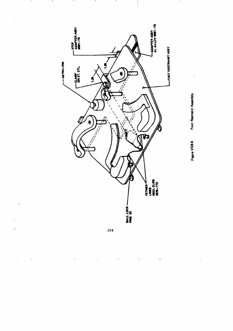
8/8/2019 MSFC Skylab Structures and Mechanical Systems Mission Evaluation
http://slidepdf.com/reader/full/msfc-skylab-structures-and-mechanical-systems-mission-evaluation 271/348
8/8/2019 MSFC Skylab Structures and Mechanical Systems Mission Evaluation
http://slidepdf.com/reader/full/msfc-skylab-structures-and-mechanical-systems-mission-evaluation 272/348
I I
i
i
' The entire assembly was checked out in a full end-to-end
simulation in the neutral buoyancy simulator facility.
d. Functional performance. Actual thermal shield deployment
on the orbiting workshop went smoothly. The poles presented a small
problem when they were unfastened from their storage pallets. The large
"0" rings snagged when the poles were pulled through the elastic restraining
straps. Also, during assembly of the poles, the clothesline was found
to be twisted around the deployment pole. This was corrected by breaking
a pole joint and rotating the outboard end of the poles. Concern was
expressed that the handling and insertion of the assembled pole into
the base plate in zero _ might prove to be a problem as well as the possibility
that an oscillation might occur in the poles that would be difficult to
dampen. ;iowever, this never auzterla[Ized and the assembly operation
went smoothly. The shield itself was noted to have retained some of the
accordian folds from packaging, but proved to be no problem. The twin-pole thermal shield was a major repair element that ensured successful
completion of the Skylab mission.
9. Waste Management System. The waste management system provides
the supplies and equipment necessary for hygenic collection, processing,
storage, and return or disposal of waste products (feces, urine, and vomitus)
for the three crewmen of each nE[ssion. A vacuum cleaner is supplied to
collect free-floatlng debris within the Skylab.
a. Fecal collection and processing.
(i) General requirements.
(a) Fecal collection. The fecal collector shall
provide the capability to collect and contain all consistencies of fecal
matter. Requirements for the collector are:
! The collector shall provide a positive means
to ensure separation, collection, and containment of the feces and wipingmaterial.
2 The collector shall not alter the constituents of
of the fecal material (including water) until a mass measurement has been
performed and its results recorded. After the mass measurement, the fecal
collection shall be vacuum dried.
! The maximum duration of each complete de-
fecation cycle (excluding defecat.on) shall not exceed 15 mln. The
cycle shall include system preparation, initiation of processing, and
preparation of the waste management system for tile next cycle. The system
shall be designed to limit initial preparation tlme to no more than 30 sec.
Z55
I
8/8/2019 MSFC Skylab Structures and Mechanical Systems Mission Evaluation
http://slidepdf.com/reader/full/msfc-skylab-structures-and-mechanical-systems-mission-evaluation 273/348
(b) Vomltus collection. Contigency fecal bags shall
be provided to collect and contain vcmltus material from the crewmen and
shall interface with the waste procetJsor and the specimen mass measurementdevice.
(c) Waste processor. The waste processor shall providefor vacuum drying the fecal and vomltus collections and debris collections
(if necessary) so that the waste products therein are deactivated and bacterial
contamination is prevented. Requirements for waste processing are:
I All fecal and vomitus collections shall b,
vacuum dried.
Each processor shall have the capability
of being individually controlled and shall include a display to indicate
when each specimen has been deactivated and is ready for storage.
Six processor_ shall be provided.
The qualification and performance require-ments for the waste processor module are:
Operating temperature-- 58 to 90 °F.
Service life--9,000 hr (including
3,360 hr active orbital environment); cycles--7,800 operational
(280 cycles/chamber i to 1 1/2 hr on, 15 min off with manifold pressure
5 psi below ambient).
(2) Mission performance.
(a) Fecal collection. The fecal collection equipment
worked successfully and the crews expressed general satisfaction
(Figure _)G9-5).
The airflow system of collecting feces was reported
r,Jbe a good concept and worked exceptionally well. However, it was felt
that _igher airflow would provide even more satisfactory results. In
order to obtain the proper seal required for good airflow collection
the hand grips were used. It was reported that excessive pulling force
on the grips was required to attain a seal.
Minor difficulties were encountered installing the
b i>_tn the fecal receptacle as the second cuff was occasionally difficult to
install on the receptacle. It was also reported that several cuffs debonded;
tiLesebags were discarded.
The time required to accomplish bag sealing, mass
,a_.asaring,and processor loading was not considered excessive. Odor control
256
8/8/2019 MSFC Skylab Structures and Mechanical Systems Mission Evaluation
http://slidepdf.com/reader/full/msfc-skylab-structures-and-mechanical-systems-mission-evaluation 274/348
was satisfactory and noise level was acceptable except during sleep
periods. There were no fecal bags damaged during use and no filter or
seal leaks.
The bag/processor interface was satisfactory. The
four top chambers were used to pcocess feces; the two lower chambers
were used to dry desiccants (PGA and film vault). At various times during
the Skylab mission all chambers were in use.
(b) Because of a procedure used by the crews, the
S_4D mass/time processing curves were never used. The SMMD was exchanged
for the wardroom SMM.D sometime during the first manned phase. There was no
noted difference oetween the specimens dried with or without heat.
(c) Waste processor. The processor was used to dry
feces and suit drying desiccants only. The processor module (Figure
VG9-1) control panels, valves, doors, dampers, and pressure plate mechanism
operated satisfactorily during the Skylab mission. No quantitiative evaluation
can be made of the drying times. However, all returned samples were acceptable
for medical analysis. It was determined that the number of collections
during the mission was approximately half the design requirement. A/so,
it was determined during flight that feces can be dryed without a heater
element by extending the processing times by approximately t0 percent.
(3) Anomalies.
(a) Collection module. No anomalies reported.
(b) Fecal bags. Several of the blar' rubber outer
cuffs came loose from the fecal bags. These bags were d.ocarded and replaced
with new bags.
(c) Processor module. The processor chamber
failed to evacuate when attempting to dry pressure su_t desiccant during the
first manned phase. It was determined by the crew that the desiccant thickness
held the saver valve closed over the vacuum port. The desiccants were
subsequently red-tagged and replaced with spare desiccants. No fulther
anomalies were reported throughout subsequent _nned phases.
(4) Recommendations.
(a) Fecal processing should be done without heat.
The increase in drying time does not warrant the complexity of an electrical
heater from the mechanical design poxnt of view.
' (b) Fecal bags should be designed with a slngle rubber
cuff since smearing of the seal did not occur. This would eliminate the
difficulty of installing the bag in its receptacle.
Z57
l l j j
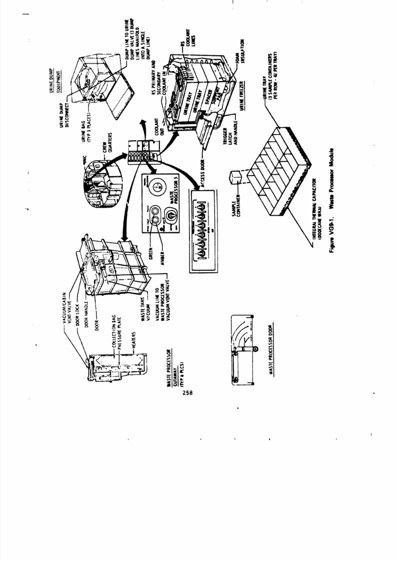
8/8/2019 MSFC Skylab Structures and Mechanical Systems Mission Evaluation
http://slidepdf.com/reader/full/msfc-skylab-structures-and-mechanical-systems-mission-evaluation 275/348
i i i l *
8/8/2019 MSFC Skylab Structures and Mechanical Systems Mission Evaluation
http://slidepdf.com/reader/full/msfc-skylab-structures-and-mechanical-systems-mission-evaluation 276/348
(c) Airflow through the fecal scdt should be In2reasedy approximately 50 percent.
b. Urine collection and sampling.
(1) General requirements.
(a) The urine collector shall provide the capability
to collect, contain determine volumed sample t and dispose of excess urine.
Require_ ,nts for the urine collector are:
The urine receiver shall completely enclose
the ,'rine stream during the collection process. The tailoff or dripping
portion of the normal urination process shall be a:commodated by the urinecollector.
2 The urine receiver and the urine collectionunit shall be operable whiie the astronaut _s restrained in the seated
or standing posttlon.
The urine collection unit shall be designed
to collect and contain the crew urine output for a 24-hr period.
The urine collector shall provide the capability
to extract representative samples of 122 ml (minimum), from a homogenous
pool, for freezing. The samples shall be frozen below -2.5 "F within8 hr.
Urine remaining after sample extraction shall
be disposed of into the waste tank. Th_ system shall provide the capability
to dispose of the urine at scheduled intervals.
6 The urine collection unit shall determine_
the volume of each 24 hr vold to an accuracy of _ 15 percent.
The urine collector shall be designed to
prevent cross-contaminat.)n between the users. A flushing capab'llty shall
be provided as a means of controlling cross-contamlnatlon between the 24-hr-
pooled urine collections for each user.
The 24-hr urine pool shall be maintainedat or below 59 °F.
The maximum time fGr each urination cycle(excluding urination) shall not exceed I- min.
I_0 The urine collection system shall interface
wltu the command _dule for transferrinK_ collecting, measuring and sampling,and dumping ,_f t_,._irinecollected during command module operations prior
to workshop _ctivatlon.
259
8/8/2019 MSFC Skylab Structures and Mechanical Systems Mission Evaluation
http://slidepdf.com/reader/full/msfc-skylab-structures-and-mechanical-systems-mission-evaluation 277/348
11 A lithium chloride tracer shall be incorporated
as the pri,_ method to detern, lne the volume of urine co]letted in each
24-hr urlne pooling period. Lithium :_nall be added in the amount of
30 _0.3 mR into each pooling bag prior to flight.
12 An alternate urine collectlon system shall
utilize Apollo-type rool-on cuffs and adapters to accommodate urine collection
directly into urine collection bags without the use cf air entrainment.
1._!3The qualification and performance z,_ulrements
for the urine separator are:
A OperaLing temperature--58 to -90 "F.
_ Operation pressure--3 to 7 psia (external:
14.7 psia higher than internal pressure).
& Service llfe--9,000 hr (1,750
operational cyclts/8-mln cycle)
(2) Mission performance.
(a) Airflow and urine collection time was considered
satisfactory by all crewmen.
(b) Noise level of the urlne separators (Figure
vGg-2) was not disturbing. However, when the system was u_ad
during sleep periods, the crewmen were occaslona_ly awakened by the separator
noise. This was not considered a problem. It is recommended, however.
that future space vehlcl? design dampen or isolate such noises during crew
s,eep and/or nonactive periods.
The one occurronce during the first manned phase
of separator filter changeout caused by the pilot's filter clogging, required
about 30 min of maintenance time.
All nine separators used during the Skylab mission
performed without incident. During the last week of the third manned phase,
it was reported by the crew that urine salts were deposited on the case
of all three separators, llowever, th_ separators continued to function
azld were used through the end of the mission.
(c) Urine drawer chillers (Figure VGN-5)
operated _ormally throughout the manned phases. Examination of ADDT datu
and real t/me data for the duration of the Skylab mission also .adic_tes
an average t,.mpetat,,re for the three chillers of 45 °F. The crews reportedn- ,,×c,:ssive buildup of _)iatu_e on the b_at exchanger plate. They did.
how_'v,r, wipe the plates daily.
Z60
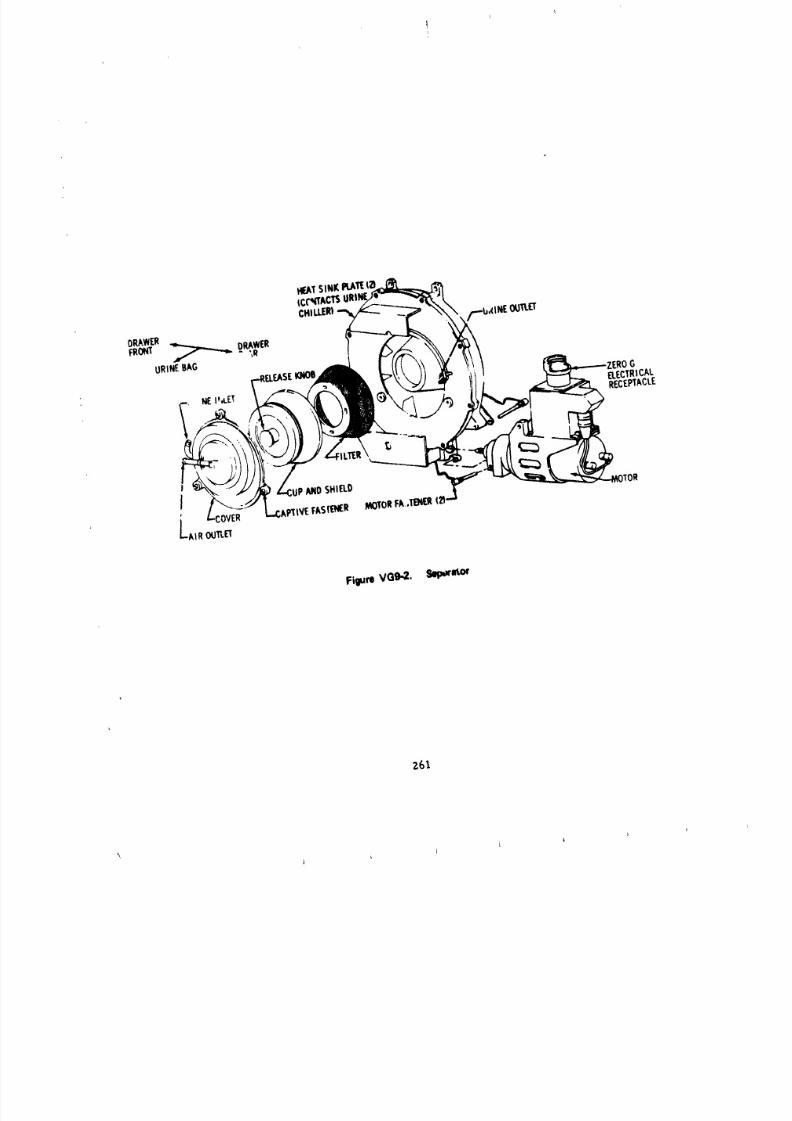
8/8/2019 MSFC Skylab Structures and Mechanical Systems Mission Evaluation
http://slidepdf.com/reader/full/msfc-skylab-structures-and-mechanical-systems-mission-evaluation 278/348
HEATSINKI_.ATIE;_
tCt"_I'ACTSCHILLER)
D_WER /'--SalNEOOTLETFRONT _ ORAWER
URINEBAG
NEI_,LET ELECTRICALRECEPTACLE
J ;PANDSHIELD
FAS'ENER MOTORFA.TENER _R
LAIR OUTLET
Figure VGg.2. Selp,wru_'
261
8/8/2019 MSFC Skylab Structures and Mechanical Systems Mission Evaluation
http://slidepdf.com/reader/full/msfc-skylab-structures-and-mechanical-systems-mission-evaluation 279/348
No difficulty was experienced installing new urine bags
in the urine bag box and on the separator. During the first manned phase,
the pilot'_ urine drawer was reported to have a tendency to stick while
closing; it was difficult to close the last inch of travel. Similarproblems were encountered during ground checkout becase of close tolerance.
The pilot of the first crew reported that he was reluctant to slam the
drawer and, thereafter, he applied a force slowly that closed the door
adequately.
The condensation in the urine drawers was minimal and
confined to the chiller plate (primarily on the bumpers). This condensation
was wiped dally.
Occasionally, the urine hoses were caught behind
the separator motor but this was corrected by ensuring that the urine hose
was not in a position to become pinched prler to closing the drawer.
(d) The accuracy of in-fllght volume measuring as
compared to post-flight lithium chloride analysis varied randomly throughout
the Skylab mission. However, it was clear that the in-flight measuring system
was most accurate at the higher collected volumes. There appeared to
be a gradual learning curve which improved the In-fllght measuring slightly
during the latter part of the missions. The sample bags arrived frozen
as planned and none of them leaked after thawing.
(3) Anomalies.
(a) During deactivation of the urine drawers by
the second crew, the science pilot found that the suction llne seal had
debonded from the flange of the suction llne. The seal was taped t= the
collector face. ExamJnatlon of a photograph (taken by the crew) and of
the qualification test collection module indicated that the failure may
have been due to an improper bond. A replacement plug seal was fabricated
for the third crew to install that solved the problem (Figure VG9-3).
(b) During the first manned phase, low airflow
was reported in urine drawer #3. The crew changed the separator filter
and the airflow became non,al. Inspection of the filter by the crew did
not reveal any visual blockage or wetting of the seal. Since the filter
was not returned, the cause of failure is not known. A single large collection
may have flooded the filter surface, blocking the flow and the continued
operation of the blower subsequently dried the fllter.
(c) Excessive alr was reported in the urine samplestaken by the first crew, resulting in low sample vclume (90 to I00 ml average
ratl_er than ]22 to 130 ml). Cycling the sample dld not remove the alr.
Z6Z
i i J J
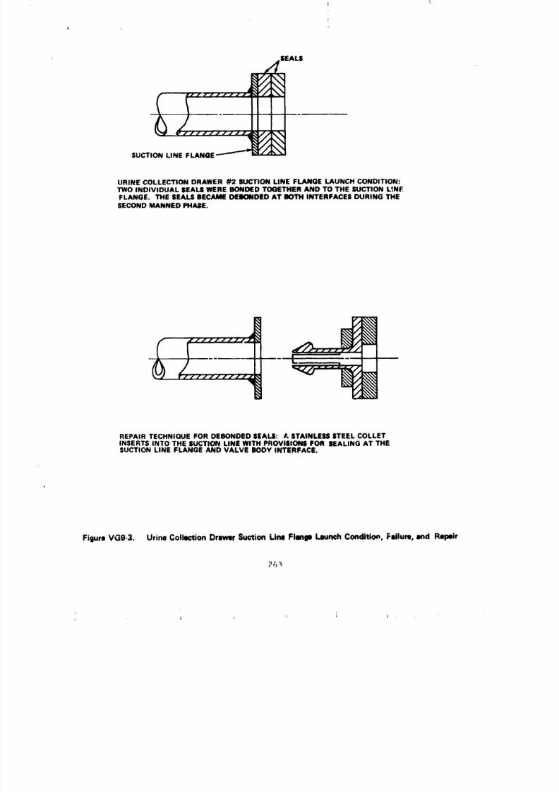
8/8/2019 MSFC Skylab Structures and Mechanical Systems Mission Evaluation
http://slidepdf.com/reader/full/msfc-skylab-structures-and-mechanical-systems-mission-evaluation 280/348
EALS
URINE COLLECTIONDRAWER _ SUCTION LINE FLANGE LAUNCH CONDITION:TWO INDIVIDUAL SEALSWEREBONDEDTOGETHERAND TO THE SUCTION L_NF.FLANGE. THE SEALSBECAMEDEBONDEDAT BOTH INTERFACESDURING THESECONDMANNEDPHASE.
REPAIR TECHNIQUE FORDEBONDEDSEALS: _, STAINLESSSTEELCOLLETINSERTSINTO THE SUCTION LINEWITH PROVISIONSFOR SEALINGAT THESUCTION LINE FLANGE AND VALVE BODY INTERFACE.
Figure vGg-3. Urine Collection Drawer Suction Line FIImp Launch Conditio_, Fsilure, and Repeir
8/8/2019 MSFC Skylab Structures and Mechanical Systems Mission Evaluation
http://slidepdf.com/reader/full/msfc-skylab-structures-and-mechanical-systems-mission-evaluation 281/348
However, keeping the pressure on the urine bag as the sample was taken worked
the best and was adopted by the second and third crews. Samples of 122 ml
were easily obtained in I g testing which could be attributed to better
separation. It is more likely, however, that the air in the collectionbag was more evenly distribured in zero g and resulted in excessive
air in the urine samples.
(d) During a trial run of stowing the urine trays
in the return container, the third crew reported difficulty inserting
the trays. Of the four positions, the outer two trays could not be fully
inserted without encountering resistance. The science pilot elected not
to force the trays further. He felt that the trays would be impossible
to remove and return to the urine freezer. The cause of the problem
was determined to be &le bags frozen above the top of the tray. Re-
moval of all the cardboard spacers from the return container did not
provide sufflcient space for the trays. In further conversations with
the crew, the science pilot stated that he thought he could force
the trays into the container adequately. This proved to he true, forduring deactivatio no additional problems were reported.
(e) Late in the third manned phase, the crew reported
a urine (ammonia) odor coming from the collection module. The odor was
apparent when the blower was opera=ing and indicated a failure of the odor
control filter.
The odor control filter was designed for 28 days of
operation, and housekeeping procedures required filter replacement halfway
through the originally planned 56-day manned phase. When the third manned
phase was extended to 85 days0 no provisions were made for additional filter
replacement. Although the filter was designed for 28 days, it was tested
for 56 days. The qualification test filter failed on the 54th say. During
the third manned phase, the second filter had been installed on aboutthe 28th day. Therefore, on the day the crew reported the odor (day 79)
this filter had been operating approximately 51 days and failed approximately
when expected.
(4) Reco_nendations.
(a) Some means of monitoring critical systems airflow
<delta pressure gages) should be provided to the crew to indicate system
p_rformance.
(b) Planned use of waste management systems during
sleep periods would neccessltate special low noise design.
_ J i j J i
8/8/2019 MSFC Skylab Structures and Mechanical Systems Mission Evaluation
http://slidepdf.com/reader/full/msfc-skylab-structures-and-mechanical-systems-mission-evaluation 282/348
(c) A better method of more effectively counteracting
the zero gravity effect, i.e., centrifuging the sample under pressure,
could be developed to remove a larger portion of the gas.
c. Vacuum cleaner.
(i) General requlrements--The general requirements forthe vacuum cleaner are:
(a) It shall be capable of collecting debris (including
free water) and particulate matter from the atmoophere of all accessible
areas of the workshop.
(b) It shall be electrlcally powered, utilizing a
universal electrlcal cable and prelnstalled electrlcal Junction boxes.
(c) It shall incorporate provisions to permit
one-handed carrying of the unit and attachments and shall be capable
of being attached to the grld floor.
(d) It shall have nonpropJlsive exhaust vents
and shall have a three-position switch for "On", "Off", and '_4omentary".
(e) The qualification and performance requirements
for the portable vacuum cleaner
O_erating temperature--58 to 90 °F.
Touch temperature--55 to 150 OF.
Operating pressure--3 to 7 psla.
Voltage--24 to 30 Vdc.
Service life--9,000 hr (1,960 cycles).
The power module requirements are the same as thosefor the vacuum cleaner.
(2) Mission performance
(a) All crews reported that the vacuum cleaner
(Figure VG9-4) worked satisfactorily, It was never used to collect wet
debris but was used primarily to clean the debris screens on the mixing
chamber and waste r_nagement compartment exhaust fan.
(b) No quantitative evaluatlon of the power module
or vacuum cleaner can be made. However, all four power modules performed
without a malfunction. The suit dryin 8 module probably was f mctioned
more than the twenty 10-hr cycles that it was tested for_ b_cause ofthe extended mission.
Z65
J j i _
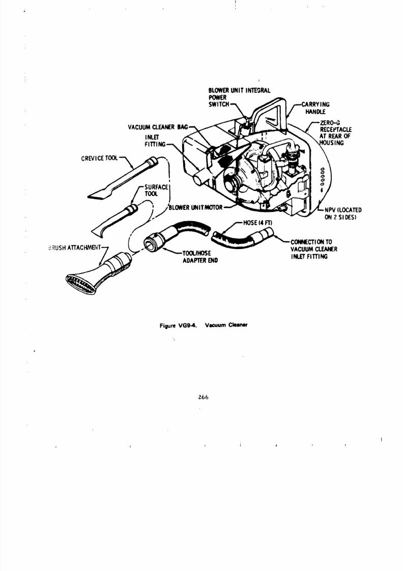
8/8/2019 MSFC Skylab Structures and Mechanical Systems Mission Evaluation
http://slidepdf.com/reader/full/msfc-skylab-structures-and-mechanical-systems-mission-evaluation 283/348
BLOWERNITINTEGRALPOWERSWITCH
HANDLE
VACUUMCLEANER RECEPTACLE
INLET ATREAROFFITTIN(
CREVICET_,!
ON2 SIDES)
HOSE4FT) CONNECTIONO
_USHATTACFIMB'_T-7-',_k'-'" _'_'/_'"--TOOLIHOSE- i VACUUMCLEANER
ADAPTE.RND INLETFITTING
FigureVG9-4. VacuumCleaner
Z66

8/8/2019 MSFC Skylab Structures and Mechanical Systems Mission Evaluation
http://slidepdf.com/reader/full/msfc-skylab-structures-and-mechanical-systems-mission-evaluation 284/348
1 ! ] _ 1
(3) Anomalies. The vacuum cleaner operated as designedand no anolaalies or malfunctions were reported.
(4) Recommendations. Within the elctrlcal powerlimitations of the Skylab, the vacuum cleaner (Ii0 W) performed
extremely well, however, the crews strongly recommended that future vacuum
cleaners be more powerful (higher nozzle delta P and higher alrtlow).
d. Component evaluation.
(i) Collection module (Figure VC9-5). The qualification
and performance requirements for the collection module are:
(a) Operating temperature-- 85 to 90 °F.
(b) Operating pressure--- 3 to 7 psia.
' (c) Thermal/vacuum
Launch: 30 to 140 °F, 26 to 0.5 psla
(0.I psl/sec blowdown rate_.
Orbit: 58 to 90 °F., 0.5 to 1.3 psia.
(d) Service llfe--9,000 hr
(e) Cycles--700 cycles at 8-mln/cycle per urine
separator system, 140 cycles at 20 mln/cycle/fecal/urlne system.
The collection equipment worked successfully and
the crews expressed general satisfaction with the collection module.
Minor difficulties were encountered installing the bag in the fecal receptacle;the se:ond cuff was occasslonally difficult to install on the receptacle.
Bag sealing was accomplished by the method which makes a 1-1n. fold
instead of )/2-in. folds. Bag sealing was always done with the blower
on, and although there were no soals that leaked, the crews conlnented
several times on the "unforgivlug" sticky adhesive on the bag. There
were no problems at the baR/processor interface.
(2) Odor control fil._r (Figure VG9-6). The
qualification and performance requirements for the odor control filter
are :
(a) Temperature-- 58 to 90 °F.
(b) Pressure-- internal, 3 to 7 psia
(c) Service llfe--28 days effectiveness (each crew
to install new unit at activation).
The odor control filter was effective for 51 to 54 days,
as compared to a design requirement of 2B days. Ourlng the third manned
phase, one unit remained in use for 51 days until an ammonia odor was noticed
by the crew. The unit was then replaced with ar,onboard spare.
Z67
' _ J J _
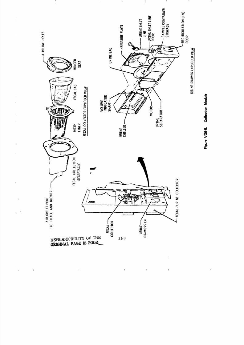
8/8/2019 MSFC Skylab Structures and Mechanical Systems Mission Evaluation
http://slidepdf.com/reader/full/msfc-skylab-structures-and-mechanical-systems-mission-evaluation 285/348I } l J I ,
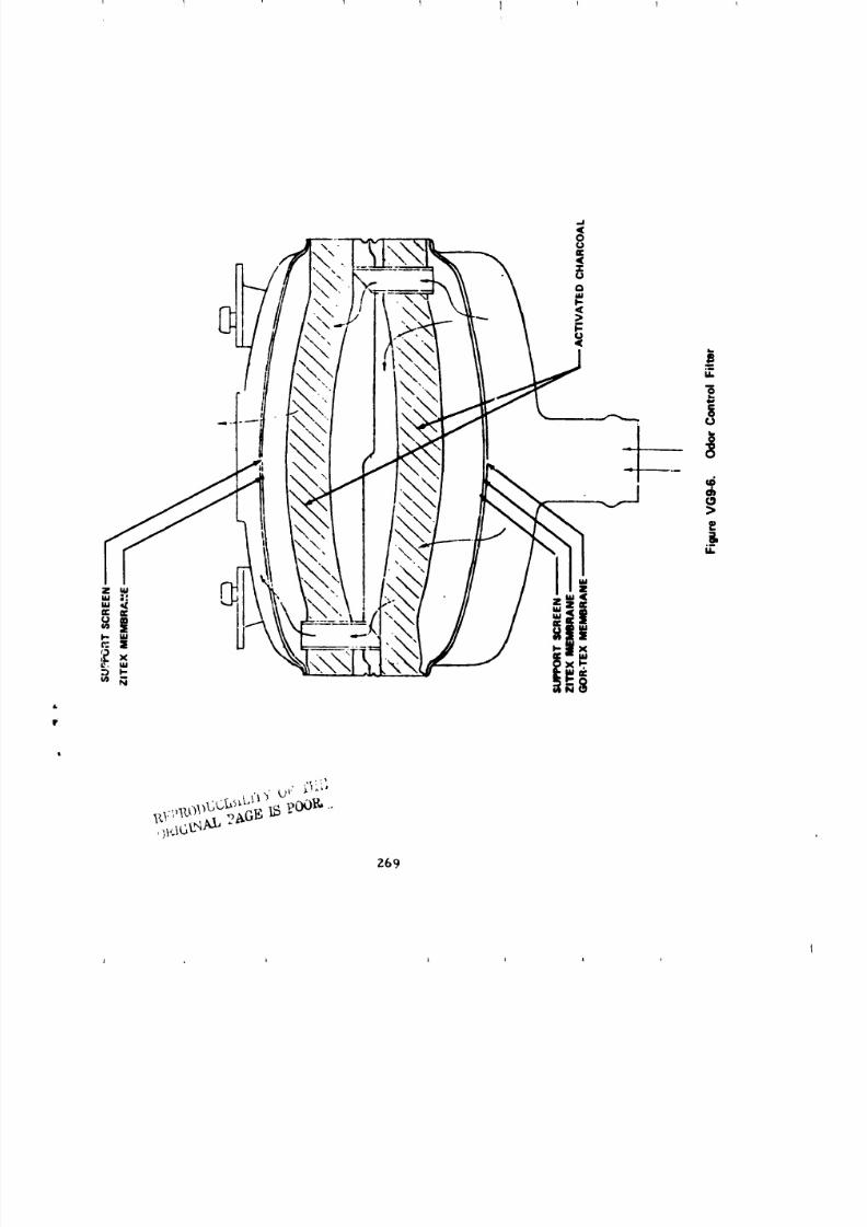
8/8/2019 MSFC Skylab Structures and Mechanical Systems Mission Evaluation
http://slidepdf.com/reader/full/msfc-skylab-structures-and-mechanical-systems-mission-evaluation 286/348
T 1 1 1 1
Z69
J _ l 1 l l l
8/8/2019 MSFC Skylab Structures and Mechanical Systems Mission Evaluation
http://slidepdf.com/reader/full/msfc-skylab-structures-and-mechanical-systems-mission-evaluation 287/348
I0. Water System.
a. General requirements for the water system are:
(I) 6,000 ib capacity.
(2) Compatibility with iodine with capability to ,_onitor
iodine concentration levels and ensure complete dispersal after iodine
[njectlon.
(3) Positive protection from freezing.
(4) Hot and celd water to prepare :meals for three crewmen
simu ]taneous ly.
(5) Visual indication of the amount of water dispensed.
(6) Warm water for personal hygiene activities and bodycleansing.
(7) A urine flush system to dispense water for daily
flushing of the individual urine collection modules.
b. Ml:_sion performance. The water system (Figure
V_;]O-l) performeJ successfully durin_ all phases of the Skylab mission.
'J'hi_ is based primarily on crew commlents since the only specific water system
data available were the nitrogen supply pressure and the water volume for
_ach of the 10 tanks. Bus current and voltage provided a limited evaluation
of water heater operation.
(I) Water storage and pressurization equipment. The I0
water tanks loaded with the required 6,000 ib of water survived the
launch envlronment with no apparent problems (FiRure VGIO-2).
Integrity of water tanks was a consideration during the first unraanned
period because of high temperatures in the vehicle. Elevated temperatures
and related water _,xpan.';ioncould have damaged the gas/water dome or bellows.
lint damage did not occur since the tanks were qualifled at 55 to 275 °F.
opera! ing temperat,ire. ('['heelevated temperature of the t_nk was only
130 "F _ The tanks were qualified at an opeLating pressure of 40 psia (max.).
'[he bellows were also qualified at the above temperatures with an operatlng
pre';_,_re of 37 psig. The servic llfe requirement of the bellows (25
_,perati;mal cycles; 100 rain., 200 max. test cycles) was adequate. No
i,r_,b],,mswere r_.p_rted during activation or deactivation of the water
t.m_ thro.gt.:.t "be t hr_e manned phases.
lh_ wat¢,r tank blank_,t heaters _ere not required since
el,: ',::_,:,.rtur_: I,vel in the water containers did not go low enough to
.,t_te the sy';t_m.
Nit ro_,en regulated to 150 psig is supplied from the airlock
and r_._;ulat,d in t},_ w(,rkshop to 35 pskg as part of the N2 distribution
m.Lwork. _ii_.r,'qu_r_.d L,|,_rdting range during activati_a was 38 to
44 p,,ia. During the second unmanned period; telemetry showed the 35 psig
aT0
1 ; ; i
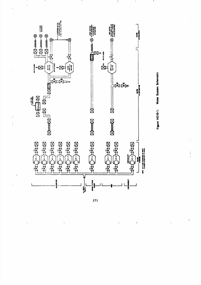
8/8/2019 MSFC Skylab Structures and Mechanical Systems Mission Evaluation
http://slidepdf.com/reader/full/msfc-skylab-structures-and-mechanical-systems-mission-evaluation 288/348
Z71
1 l 1
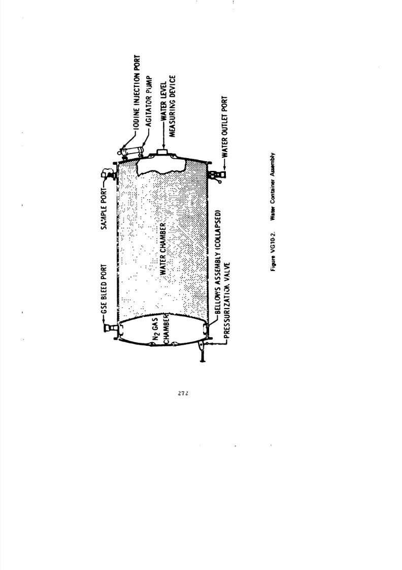
8/8/2019 MSFC Skylab Structures and Mechanical Systems Mission Evaluation
http://slidepdf.com/reader/full/msfc-skylab-structures-and-mechanical-systems-mission-evaluation 289/348
i
Ul_:i:.::.:.: .!..:._::!i::i::i.:;:i:i.i:!.;iiiii!!iiiii!!!ill' ._
"I_" "i'":! :""""" :!!':'i'i"ill:i':.:.i:i'iiiii!il.._i:_'i!ii:i::..yi::i j i:::i;!".:i!..-i:iiT:i,ii.%iiiii.iI: • • : "" :"" " •• .':. "":'.'. "::""'::"::::::-':':" """;'" • ," : " ,':::"::,'"::': :,,,:.::,:,::,',-:,,:': '::, I_..... • • " • ". ..... ",','*',%Y.','.'. ,' LLII" "" " "" " . ". . .'.','.','.'.',','.'.','.'."• . • . .........:...:.:.:.:...:...:.:.:.:."R:" ":'. : ." I_ •. :". :::::::::::::::::::::::::::.
"("".""" • • _ •>..'.:'":::i::"iii..:ii:_,, ". _.": ".:""::.:':::..":::::'. o
... . • . . (,,3::.: . : ......:............-.
_,: ": _...:: ..:.::':.:':;:..:'.:':..I,_•,,-- _ "" • .. _" ": • ":::.:.:":::':':."! t_
Ii "'.""_, ".":':: ":i::'i.i-..K.!:::::lI: .." . .m,_....:. .:"":.i.:::...:.I _ ,_if ." .'. "..': • ""'..:'::..':":'_ _ _,• " • ":':'"::'[!.'.':i:i.:::.:"'"_
,--I " ." • •• ": ".:.'.:-:."
I,,*.J IF .... ""..:" .'""""11 ,.-i -"_ . . ." . ......'..::'.'.• --, I_J_ " • .. " :.." """'"'., '11 I.*J _• "'....." -- _ .,_:_'".:'-":'"."a '_ ""
.. . • .._ ... _,y-- ":... :_
L.ii.l ' _ Fi'_ '-_'
272
i
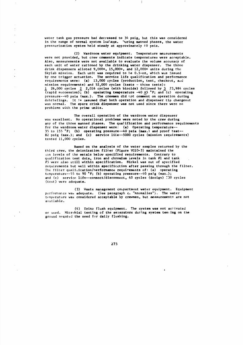
8/8/2019 MSFC Skylab Structures and Mechanical Systems Mission Evaluation
http://slidepdf.com/reader/full/msfc-skylab-structures-and-mechanical-systems-mission-evaluation 290/348
water tank gas pressure had decreased to 34 psig, but this was considered
in the range of normal system lea'=afqe. _uring manned phases, the water
pressurization system held _teady at approximately 40 psla.
(2) Wardroom water equipment. Temperature measurements
were not provided, but crew comments indicate temperatures were acceptable.
Also, measurements were not available to evaluate the volume accuracy of
each unit of water rationed by the drinking water dispenser. The three
drink dispensers alloted 9,000+, 15,000+, a_d 12,000+ units during the
$kylab mission. Each unit was required to |,e0.5-oz, which was issued
by one trigger actuation. The service llfe qualification and performance
requirements were: (a) 13,000 cycles (productlon_ test, checkout, a,d
mission requirements) and 52,000 cycles (tests - three tests):
26,000 cycles _ 2,0!6 cycles (with bioclde) followed by _ 23,984 cycles
(rapid succession); (b) operating temperature -40 +5 "F; and (c) operating
pressure--40 psia (max.). The crewmen did _ot comment on operation during
debrleflngs. It :A =ssumed that both operation and dispenser tip changeout
was normal. The spare drink dispenser was not used since there were noproblems with the prime units.
The overall operation of the wardroom water dispezlser
was excellent. No operational problems were noted by the crew during
any of the three manned phases. The quaJiflcation and performance requirements
for the wardroom water dispenser were: (a) Operating temperature--
35 to 155 "F; (b) opezatlng pressure--40 psla (max.) and proof test--
82 psig (max.); and (c) service llie--5000 cycles (mission zequlrementg)
tested II,000 cycles.
Based on the analysis of the water samples returned by the
third crew, the deionization filter (Figure VGIO-3) maintained the
ton levels of the metals below speclfled requirements. Contrary to
qualification test data, iron and chromium ievels In tank #I and tank
#5 were also still within specification. Nickel was out of specified
requirements but well within speciflc_tion after passing through the filter.
The filter quali_Ication/nerformance requirements of: (a) operating
temperature--55 to 90 oF; (b) operating pressure--40 ps_g (ma::.);
and (c) service llfe--connect/disconnect, 40 cycles (design) _DO cycles
(test) were adequate.
(3) Waste management compartment water equipment. Equipment
purfo:_aece wa_ adequate. (See paragraph c. "Anomalies"). The water
t_.mperature was considered acceptable by crewmen, but measurement_ are notavailable.
(4) Urine flush equipment. The system was not activatedor used. Mlcrobial testing of the separators during system testing on the
ground negated the need for daily flushing.
_73
A
8/8/2019 MSFC Skylab Structures and Mechanical Systems Mission Evaluation
http://slidepdf.com/reader/full/msfc-skylab-structures-and-mechanical-systems-mission-evaluation 291/348
WATER
INLET
QUICK
DI:
CARTHIDGE FILLED
WITH RESIN PEBBL-':ABIK)RB METAL* ;C
CONTAMINANTS INWATEtt
FIODINF. Ik ,_ECI'ION' /1_0_ qT
/
. !'_.'_-------4)iNF.NJECTION VALVE
Figure VG10-3- Deioniz_ir, n Fittlx
Z?4
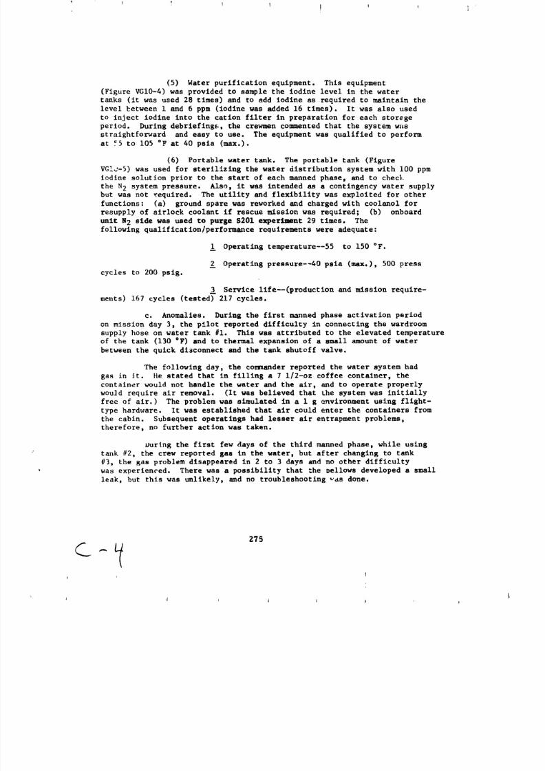
8/8/2019 MSFC Skylab Structures and Mechanical Systems Mission Evaluation
http://slidepdf.com/reader/full/msfc-skylab-structures-and-mechanical-systems-mission-evaluation 292/348
(5) Water purification equipment. This equipment
(Figure VGI0-4) was provided to sample the iodine level in the water
tanks (it was used 28 times) and to add Iodine as required to maintain the
level £etween i and 6 ppm (iodine was added 16 times). It was also used
to inject iodine into the cation filter in preparation for each storage
period. During debriefinge., the crewmen commented that the system was
straightforward and easy to use. The equipment was qualified to perform
at Y5 to 105 °F at 40 psia (max.).
(6) Portable water tank. The portable tank (Figure
VGIc-5) was used for sterilizing the water distribution system with i00 ppm
iodine solution prior to the start of each manned phase, and to checL
the N2 system pressure. Also, it was intended as a contingency water supply
but was not required. The utility and flexibility was exploited for other
functions: (a) ground spare was reworked and charged with coolanol for
resupply of airlock coolant if rescue mission was required; (b) onboard
unit N2 side was used to purge S201 experiment 29 times. The
following qualification/performance requirements were adequate:
Operating temperature--55 to 150 °F.
Operating pressure--40 psia (max.), 500 press
cycles to 200 psig.
Service life--(production and mission require-
ments) 167 cycles (tested) 217 cycles.
c. Anomalies. During the first manned phase activation period
on mission day 3, the pilot reported difficulty in connecting the wardroom
supply hose on water tank #i. This was attributed to the elevated temperature
of the tank (130 °F) and to thermal expansion of a small amount of water
between the quick di3connect and the tank shutoff valve.
The following day, the commander reported the water system had
gas in Jr. He stated that in filling a 7 I/2-oz coffee container, the
container would not handle the water and the air, and to operate properly
would require air removal. (It was believed that Lhe system was initially
free of air.) The problem was simulated in a I g environment using flight-
type hardware. It was established that air could enter the containers from
the cabin. Subsequent operatings had lesser air entrapment problems,
therefore, no further action was taken.
ourlng the first few days of the third manned phase, while using
tank #2, the crew reported gas in the water, but after changing to tank
#3, the gas problem disappeared in 2 to 3 days and no other difficultywas experienced. There was a possibility that _he bellows developed a small
leak, but this was unlikely, and no troubleshooting yes done.
I J _ l J 1 j
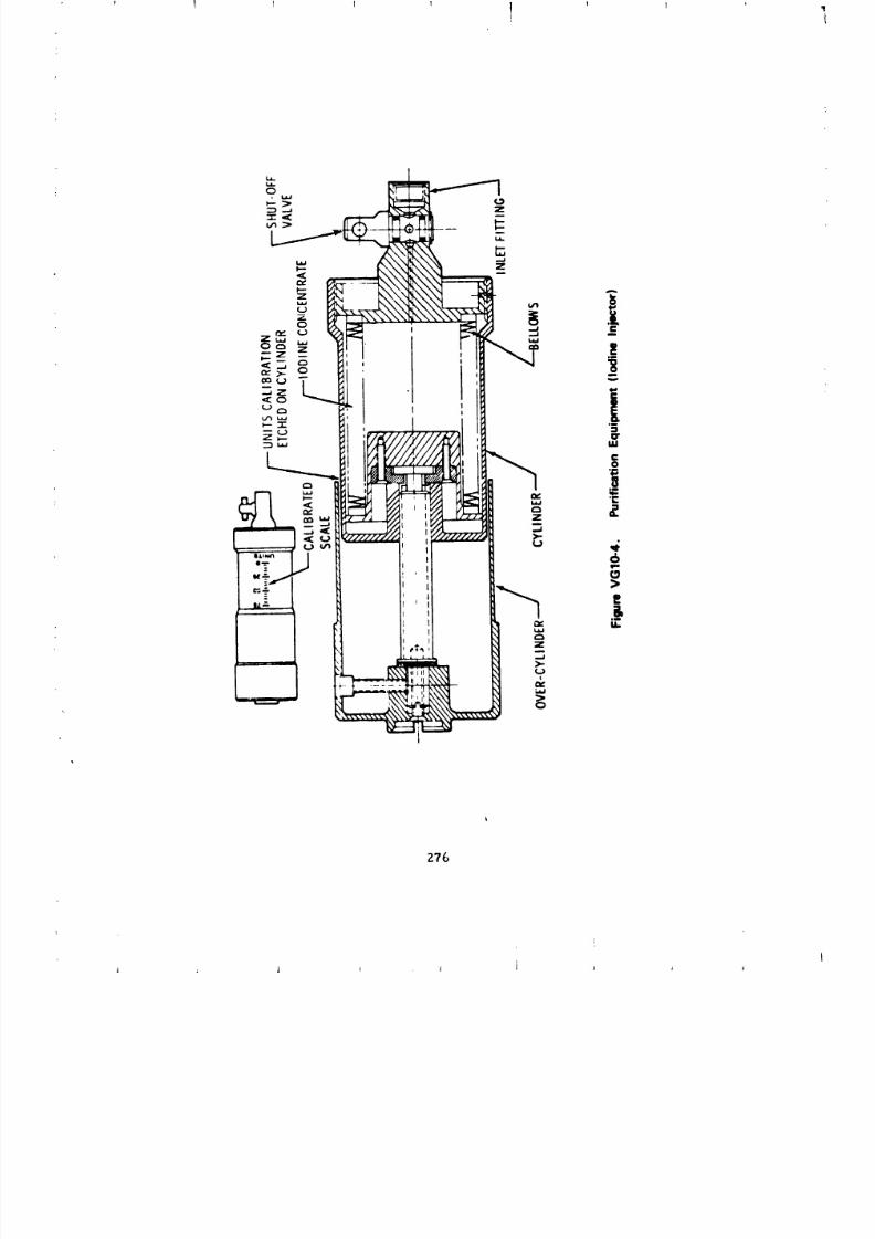
8/8/2019 MSFC Skylab Structures and Mechanical Systems Mission Evaluation
http://slidepdf.com/reader/full/msfc-skylab-structures-and-mechanical-systems-mission-evaluation 293/348
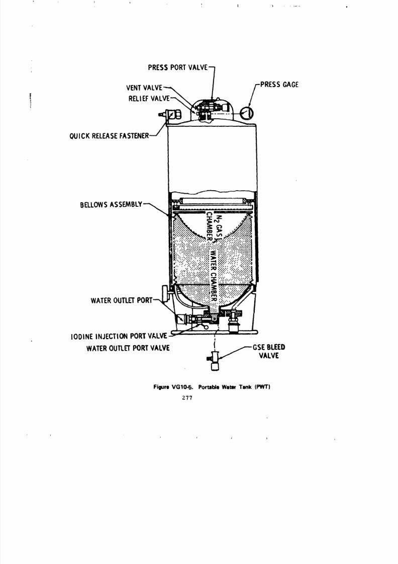
8/8/2019 MSFC Skylab Structures and Mechanical Systems Mission Evaluation
http://slidepdf.com/reader/full/msfc-skylab-structures-and-mechanical-systems-mission-evaluation 294/348
i, ] l ....
PRESSPORT
VENT GAGE
RELEF
QUICKRELEASEASTENE
WATEROUTLET
IODINEINJECTIONPORTVALVE I
1WATEROUTLETORTVALVE ._L ._GSE BLEED
VALVE
Figure VGIO-5. Portable Water Tank (PWT)
Z77
L
A i j i
8/8/2019 MSFC Skylab Structures and Mechanical Systems Mission Evaluation
http://slidepdf.com/reader/full/msfc-skylab-structures-and-mechanical-systems-mission-evaluation 295/348
Bus current data on day 56 of the third manned phase showed
an abrupt increase in "ON" time of the wardroom water heater. The he_:ter
resistance was estimated and showed an abrupt increase. Behavior of =be
heater during qualification tests indicated that the silicon covered
Inconel heater element could deteriorate in the iodized water and not meet
the qualification requirements of: operating temperature for the wardroom
heater - 150 +5°F for 3,360 hours and for the WMC heater - 127 +
5°F for 3,360 hr . Service llfe: design requirement - 9,000 hr and
mission requirement - 3,360 hr . Since the tests indicated that the
silicon covered heater element could deteriorate, it was concluded that one
of the two heater elements had failed and as a result the water temperature
remained the same but recovery time was longer. A similar increase in "ON"
time of the waste management compartment heater was noted 18 days later.
Figure VGIO-6 compares the heater resistance trend during the Skylab misslon
to qualification test data. Figure VGIO-7 graphically depicts the heaters'
configuration. Spare water heaters were onboard the workshop to allow replace-
ment if complete failure occurred; however, replacement was not required
because of the longer-than-expected heater llfe, which can be attributed to
lower iodine concentrations and zero g effects. These spares were flown
since delivery of redesigned elements with ceramic wire would not meet
the workshop schedule.
During activation (mission day 3 of the first manned phase),
a check of the waste management system line pressure was requested by
the colander. Evacuation of the line to a specified 0.2 psia minimizes
gas entrapment when the system is filled with water, but the minimum pressure
obtainable during a previous condensate tank dump was 0.77 psia. This higher
pressure allowed some gas entrapment, but was determined to he acceptable
since it would be purged out during normal use.
Twenty days later, a decrease in flow of the waste management
compartment water dispenser was reported. The crew replaced the assembly
with the spare unit and reported flow to be normal. The unit was returnedand fal]ure analysis disclosed that the seal was smaller than required.
Further invest[gatlon disclosed that neoprene rather than Viton was used.
When the dispenser was disassembled, a white powdery residue was caked
on the inlet snap ring and a white, flaky residue in all outlets. It
appeared to be a soap residue, but analysis showed it to be a product caused
by the attack of iodine on the beryllium copper retaining ring. New seals
of the proper material were supplied and a reworked spare dispenser was
launched wit|, the second crew.
During the second manned phase activation, the dump llne pressure
transducer was found to be inoperative (off-scale high). Nothing conclusive
as a failure is known since no troubleshooting was done. A work around
procedure (timing of dlmp) was developed and activation continued.
On mission day 56 of the second manned phase, the washcloth
squeezer piston seal (Ba]seal) (Figure VGI0-8) was replaced because of
the leakaKe that randomly began on mission day 15. Examination by the colander
Z78
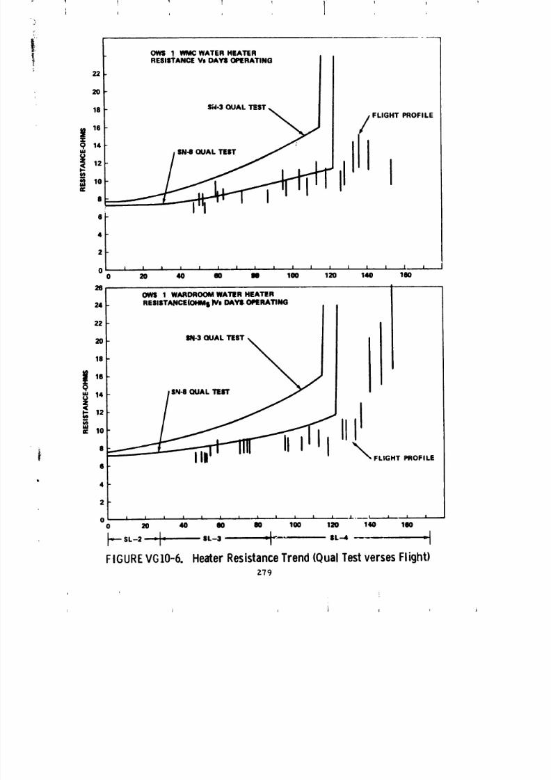
8/8/2019 MSFC Skylab Structures and Mechanical Systems Mission Evaluation
http://slidepdf.com/reader/full/msfc-skylab-structures-and-mechanical-systems-mission-evaluation 296/348
OWS 1 _ WATER HEATER
RESISTANCEVI DAYS OPERATING
22
2O
1618 S;13 QUAL TEST_ _ FLIGHT PROFILEi 14 '
i",o II I8
S
4
2
0 _ i i t i i I i i I I I I I I | I0 20 40 " " 1" 120 140 1(10
261 OWl 1 WARDROOMWATER HEATER
24 I RESISTANCE(OHMsIV. DAYS OPERATING
f \0 Im13QUAL TEST
18
14 $N8 GUAL TErr
12
II0
FLIGHT PROFILES
4
2
0 i i I I i I I i i i i i .i.. _ L=.,,....,..i==-- i ,0 20 40 80 O0 100 |2O '140 160
_'- SL-2 "I" SL-3 7|<"" SL-4 --- II
FIGUREVG10-6. HeaterResistancerend(QualTestversesFlight)
Z79
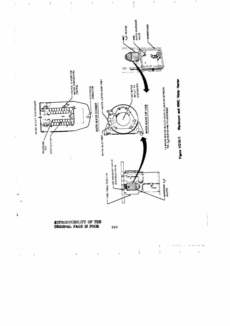
8/8/2019 MSFC Skylab Structures and Mechanical Systems Mission Evaluation
http://slidepdf.com/reader/full/msfc-skylab-structures-and-mechanical-systems-mission-evaluation 297/348

8/8/2019 MSFC Skylab Structures and Mechanical Systems Mission Evaluation
http://slidepdf.com/reader/full/msfc-skylab-structures-and-mechanical-systems-mission-evaluation 298/348
Zt41
8/8/2019 MSFC Skylab Structures and Mechanical Systems Mission Evaluation
http://slidepdf.com/reader/full/msfc-skylab-structures-and-mechanical-systems-mission-evaluation 299/348
showed the seal to be folded back in at least one area, allowing water
to leak past the piston. As a result, three additional spare Balseals were
launched with the third crew who reserviced the washcloth squeezer ancL no
further problems or anomalies were reported. This early m_intenance was
brought about by either or both: (i) inferior quality of initial lubrication;
or (2) accumulation of grime during extended use. The crew did report
increasingly higher operating forces. Consequently, a maintenance procedure
was developed by MEFC to clean, lubricate, and adjust the bearing screws;
once compl,,tf-d, operation returned to normal. The normal operating
requirements were: lever hand load--2.6 to 30 ib for 1,176 squeeze
cycles, mechanism--5,980 cycles (design) and 13,000 cycles (test), and a
servic,, life ,,f 140 days.
d. Recommendations. The washcloth squuezer was intended to
be a low cost improvement to the washcloth bathing scheme. The hardware
performance and overall scheme were reasonably successful, but it is
felt that this is an area for improvement for future designs. Future
wet cloth squeezers should be designed with protected main seals and with
mechanisms less susceptible to grime and contamination.
The problems related to the failure of the onboard water heater
element were expected since they occurred during long duration qualification
tests. Spare water heaters were onboard to allow replacement if required.
A heater element encased in metal (Cal-rod type) was d,signed and tested
for the backup workshop. The new configuration should be considered for
any future project.
Material compatibility is a very important aspect in systems
such as the waste management compartment water system and should be given
special consideration.
]I. Refrigeration Syste_m (Figure VGII-I).
a. Ceneral requirements.
(1) The temperature of the urine pool shall not exceed
59 °F for more than an accumulated time of 3 hr during a 24-hr
period.
(2) A freezer shall be p.'ovlded to freeze urine and blood
samples.
(3) A return container shall be provided for transferring
the frozen urine and bloo4 samples from the workshop to earth by way of
the ¢:ommand module.
ZSZ
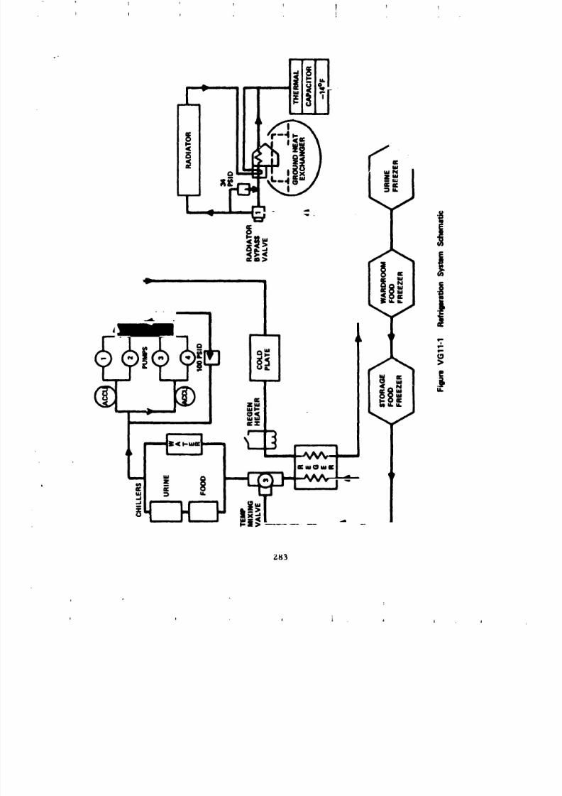
8/8/2019 MSFC Skylab Structures and Mechanical Systems Mission Evaluation
http://slidepdf.com/reader/full/msfc-skylab-structures-and-mechanical-systems-mission-evaluation 300/348
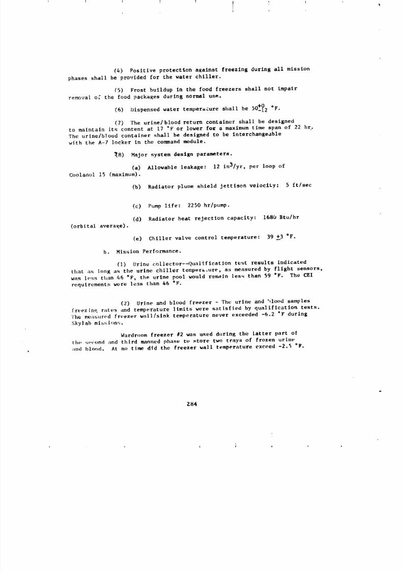
8/8/2019 MSFC Skylab Structures and Mechanical Systems Mission Evaluation
http://slidepdf.com/reader/full/msfc-skylab-structures-and-mechanical-systems-mission-evaluation 301/348
(4) Positive protection against freezing during all mission
phases shall be provided for the water chiller.
(5) Frost buildup in the food freezers shall not impair
removal o; the food packages during normal us_.
.o+O o(6) Dispensed water temperature shall be _ -12 F.
(7) The urlne/blood return container shall be designed
to maintain its content at 17 °F or lower for a maximum time span of 22 hr,.
The urine/blood container shall be designed to be interchangeable
with the A-7 locker in the command module.
_8) Major system design parameters.
(a) Allowable leakage: 12 in3/yr, per loop of
Coolanol 15 (maximum).
(b) Radiator plume shield Jettison velociLy_ 5 ft/sec
(c) Pump life: 2250 hr/pump.
(d) Radiator heat rejection capacity: 1680 Btu/hr
(orbital averaKe).
(e) Chiller valve control temperature: 39 _3 °F.
b. Mission Performance.
(l) Urine collector--Quallfication test results indicated
that ;is long as the urine chiller tempera.ure, as measured by flight sensors,
was less than 46 "F, the urine pool would remain less than 59 °F. The CEI
requirements were less than 46 °F.
(2) Urine and blood freezer - The urine and "_lood samples
freezin,, rates and temperature limits were satisfied by qualification tests.
The measured freezer wall/sink temperature never exceeded -6.2 °F during
Sky] ab missi¢,n'_.
Wardroom freezer #2 was used during the latter part of
th¢_ s,,cond and third ,_nned phase to store two trays of frozen urineand blood. At no time d_d the freezer wall temperature exceed -2.5 °F.
Z84
t
I l
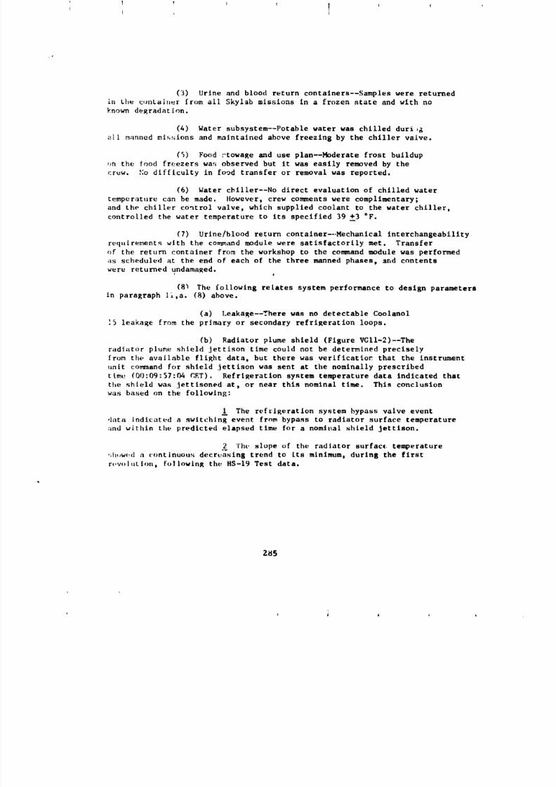
8/8/2019 MSFC Skylab Structures and Mechanical Systems Mission Evaluation
http://slidepdf.com/reader/full/msfc-skylab-structures-and-mechanical-systems-mission-evaluation 302/348
(3) Urine and blood return contalners--Samples were returned
in Che c,mtaiT)er from all Skylab missions in a frozen state and with no
known degradation.
(4) Water subsystem--Potable water was chilled duri,g
all manned missions and maintained above freezing by the chiller valve.
(5) Food J-towage and use plan--Hoderate frost buildup
on the food freezers wa_ observed but it was easily removed by the
crew. _;odifficulty in food transfer or removal was reported.
(6) Water chiller--No direct evaluation of chilled water
temperature can be made. Ilowever, crew cora_ents were complimentary;
and the chiller control valve, which supplied coolant to the water chiller,
controlled the water temperature to its specified 39 _3 *F.
(7) Urine/blood return container--.Mechanical Interchangeability
requirements with the command module were satisfactorily met. Transfer
of the return container from the workshop to the command module was performed
_isscheduled at the end of each of the three manned phases, and contents
were returned undamaged.
(8_ The following relates system performance to design parametersin paraRraph ll,a. (8) above.
(a) Leakage--There was no detectable Coolanol
15 leakage from the primary or secondary refrigeration loops.
(b) Radiator plume shield (Figure VGII-2)--The
radi_tor plume shield Jettison time could not be determined preciselyfrom the available flight data, but there was veriflcatio_ that the instrument
unit co,and for shield jettison was sent at the nominally prescribed
t(me (00:09:57:04 CET). Refrigeration system temperature data indicated that
the shield was jettisoned at, or near this nominal time. This conclusion
was based on the following:
The refrigeration system bypass valve eventdata indlcated a switching event fro_ bypass to radiator surface temperature
;md within the predicted elapsed time for a nomlz_al shield Jettison.
The slope of the radiator surface temperature
._h,,w_d a (.ontinuous decreasing trend to its minlmum_ during the first
r_.w_lution, following the HS-19 Test data•
285
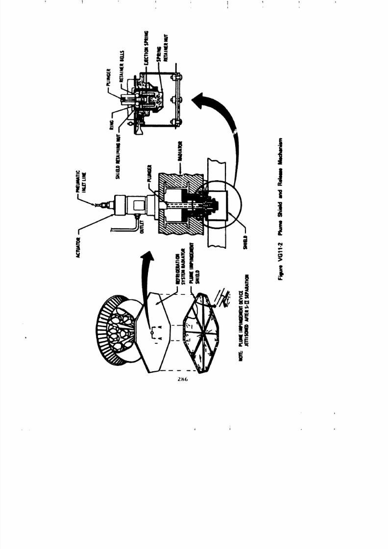
8/8/2019 MSFC Skylab Structures and Mechanical Systems Mission Evaluation
http://slidepdf.com/reader/full/msfc-skylab-structures-and-mechanical-systems-mission-evaluation 303/348
! 1
2KG
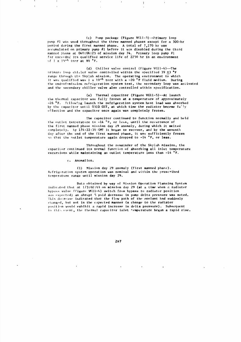
8/8/2019 MSFC Skylab Structures and Mechanical Systems Mission Evaluation
http://slidepdf.com/reader/full/msfc-skylab-structures-and-mechanical-systems-mission-evaluation 304/348
(c) Pump package (Figure VC,ll-3)--l'rlmary loop
pump #l was used throughout the three manned phases except for a 300-hr
period ddrlng the first manned phase. A total of 7,270 hr was
accumulated on primary pump #I before it was disabled during the thlrd
_anned phase at 040:06:23 of mission day 74. Primary loop pump #l
far exc(-,ded its qualified service life of 2250 hr in an environmentof ] × ]O-6 torr at 80 °F.
(d) Chiller valve control (Figure VGll-4)--The
r)rimarv loop chiller valw, controlled within the specified 39 +__3_F
range through tee Sky!ab mission. The operating environment to which
it was qualified was l x 1.0-6 tort with a -20 °F fluid medium. During
the end-of-mission refr_geration system test, the secondary loop was activated
and the secondary chiller valve also controlled within specification.
(e) Thermal capacitor (Figure VGll-5)--At launch
the thermal capacitor was fully frozen at a temperature of approximately
-26 °F. Fcllow._ng launch the refrigeration system heat load was absorbedby the capacitor until 0310 GET, at which time the radiator became fu'!y
effective and the capacitor once again was completely frozen.
The capacitor continued to function normally and held
the outlet tem!_erat.re to -14 °F, or less, until the occurrence of
the first manned phase mission day 29 anomaly, during which it melted
completely, Ly 174:22:30 t,_fr it began to recover, and by the seventh
day after the end of the first manned phase, it was sufficiently frozen
s¢_ that the outlet temperature again dropped to -14 °F, or leas.
Throughout the remainder of the Skyl_h mission, the
capacizor continued its normal function of absorbing all inlet temperature
excursions while maintaining an outlet temperature less than -14 °F.
c. Anoma I ies.
(1) Mission day 29 anomaly (first manned pha_e).
Refrig_.ration system operation was nominal and within the prescribed
temperature range until mission day 29,
Data obtained by way of Hission Operation Planning System
indic,_t_,d theft at 113:02:0"1 on mission day 29 (at a time when a radiator
bypa_ wllw' (Vlgur_, _;ll-h) switch from bypass to radiator position
was _,xl,_,ct_,d) an abrupt 5 psid decrease in pump delta pressure was noted.
Thiq de_r,,asf, indicated that the flc_ path of the coolant had suddenly
c'l,aas_+.d, b,nt not in the c xpected manner (a change to the radiator
po_itl,,n wo, ld t.xhlhit a rapid increase in delta pressure). Subsequentto thi'. ,.v,.nt, the. th_.rmal capacitor inlet *0.mperature began a rapid r_se.
Za7
J _ A i
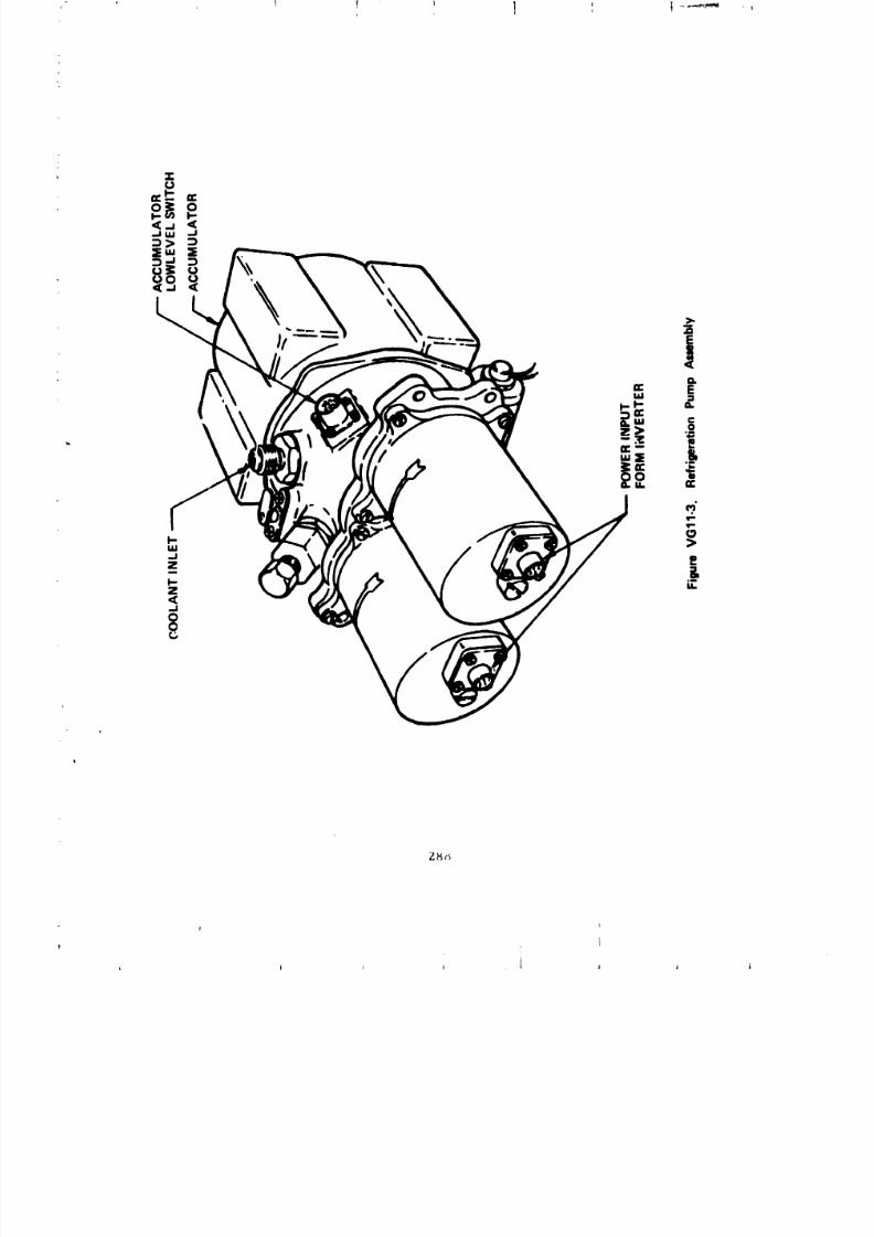
8/8/2019 MSFC Skylab Structures and Mechanical Systems Mission Evaluation
http://slidepdf.com/reader/full/msfc-skylab-structures-and-mechanical-systems-mission-evaluation 305/348l
i 1 i I 1 I 1 i
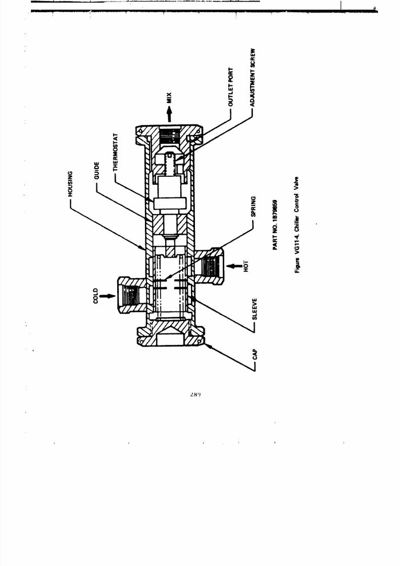
8/8/2019 MSFC Skylab Structures and Mechanical Systems Mission Evaluation
http://slidepdf.com/reader/full/msfc-skylab-structures-and-mechanical-systems-mission-evaluation 306/348
I|
l
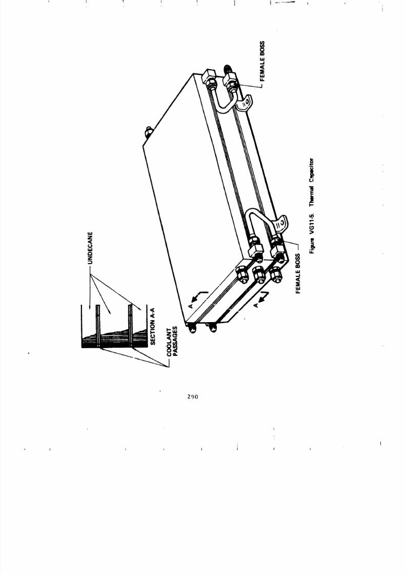
8/8/2019 MSFC Skylab Structures and Mechanical Systems Mission Evaluation
http://slidepdf.com/reader/full/msfc-skylab-structures-and-mechanical-systems-mission-evaluation 307/348
290
]
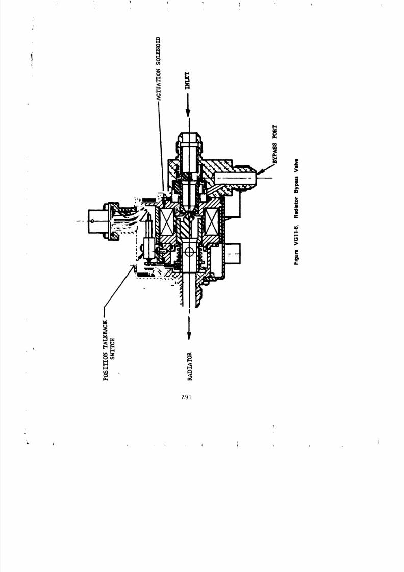
8/8/2019 MSFC Skylab Structures and Mechanical Systems Mission Evaluation
http://slidepdf.com/reader/full/msfc-skylab-structures-and-mechanical-systems-mission-evaluation 308/348
I

8/8/2019 MSFC Skylab Structures and Mechanical Systems Mission Evaluation
http://slidepdf.com/reader/full/msfc-skylab-structures-and-mechanical-systems-mission-evaluation 309/348
8/8/2019 MSFC Skylab Structures and Mechanical Systems Mission Evaluation
http://slidepdf.com/reader/full/msfc-skylab-structures-and-mechanical-systems-mission-evaluation 310/348
1 !
(1) Preftltration for valves. Large capacity filters,
15 micron absolute (or better), should be installed b_tween sensitive
valves _ith close tolerance fits end any potential contaminant generators
(pumps, heat exchangers , etc.). They should be installed a_ close
to the upstream valve port as is feasible.
(2) Filter location. To prevent filter blockage by
ice crystal formation, as a result of minute amounts of water usually
found in refrigerants, filters should not be installed at cold locations.
(3) Use of orifices. Systems using flow diverting valve
shouldj if addit±onal pressure drop is acceptable, use a flow-limitingorifice in the branch least sensitive to flow variations in the event
of a flow split caused by a valve malfunction.
(4) Leakage. No dis,:ernable leakage was experienced
during the Skyiab mission. Maximum use of brazed Joints and careful use ofspecialized mass spectrometer methods of leak testing wlll be necessary
if similar success with £uture systems is to be achieved.
(5) Component life. Four pumps were needed in each workshop
refrigeration system loop to meet Skylab mission life requirements. Since
essentially only one pumn in each loop was used during the mission, future
system design need not be 8o conservative if pump life can be predicted
or verified by test (Figure VCll-1).
(6) Redundancy. The philosophy of redundancy should
be re-examined since each of th_ two identical workshop systems experienced
similar anomalies with the possibility that the same component in _ach loopmalfunctioned.
•
293
8/8/2019 MSFC Skylab Structures and Mechanical Systems Mission Evaluation
http://slidepdf.com/reader/full/msfc-skylab-structures-and-mechanical-systems-mission-evaluation 311/348
8/8/2019 MSFC Skylab Structures and Mechanical Systems Mission Evaluation
http://slidepdf.com/reader/full/msfc-skylab-structures-and-mechanical-systems-mission-evaluation 312/348
13. Special Prolects Hardware. The performance of special hardware
developed as a result of the orbital workshop meteoroid shield/solar array
system anomalies that occurred during launch Is covered in this section.
It was theorized, since no photographs, TV coverage, etc., was available
during the first unmanned period, that the undeployed beam fairing on the
solar array system wing #i was restricted by a portion of the meteoroid
shield debris. The special hardware subsequently developed and built
by the MSFC to remove the restriction was based on this theory and the
photographs taken later by the first crew (Figure VG3-8) bears
the theory out as valid. It was also learned from these photographs
that the restricting debris did in fact resemble a strap which was im-
bedded in the honeycomb fairing of the beam allowing only a 5° - i0 ° deployment.
A concerted design and build effort took place at the MSFC, as well
as facilities of several contractors who were asked to Join the effort
to develop the special debris removal/cuttlng tools required _o free
the restricted solar array system beam fairing. An around-the-clock
effort by civil service and contractor personnel was initiated during
which several design concepts were evaluated. Among those considered were:the use of a bone saw; a chisel and hammer; an oxyacetylene
torch; special tools for sawing (manual and powered); a solbr parabolic
mirror system for burning; cutting with mechanical shearing devices; and
severing or prying with special designed instruments. The sawing, chiseling,
and hammering-type tools were rejected bacause they were considered unsafe
for space use because of their potential for causing space suit punctures.
To use them the astronauts would be required to move too close to the torn/
Jagged edges and corners of the anomalous aeea for the proper and accurate
operation of the tools, and the resultant residue cuttings would, themoelves,
be potential contaminate debris. The oxyacetylene torch and solar
parabolic mirror system were also discarded because they were not readily
adaptable to space use because of the nonexlstance of: (I) a suitable
gas regulator for the torch; and (2) a rigidly pl_formed sun alignment/following device for the mirror system. A matrix of the tools and the
task accomplishment considerations is shown in Table 13-1.
As a result of the considerations listed above, only the cutters,
shears, and the prying/severlng (universal tool) concepts remained as
candidates for further investigation and development. Commercial and
Government suppliers of these type tools were consulted regarding avail-
ability of off-the-shelf hardware that could be expeditously modified/adapted
for space use within the very limited time frame before the first manned
phase llft-off (approximately i0 days). One prying (universal) and two
cutting (shears and cable cutters) tools were designed and manufactured
by the MSFC within the required time, were stowed aboard the first mannedcommand service module, and subsequently flown to the orbiting unmanned
laboratory. An evaluation of these tools follows:
a. Evaluation. The three special tools developed by MSFC
were deslgned to fit the end of a tubular aluminum interlocking utility
295
J J _ I l ,
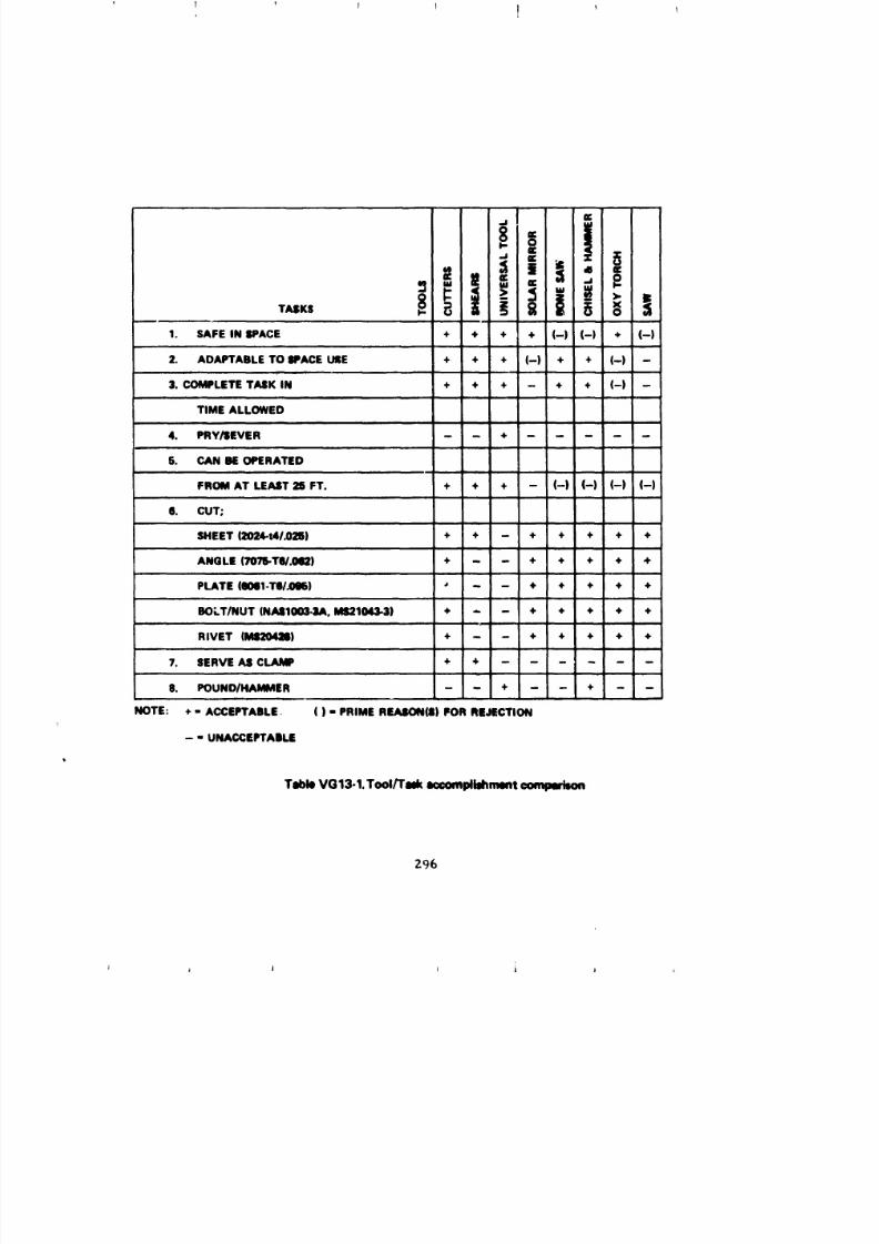
8/8/2019 MSFC Skylab Structures and Mechanical Systems Mission Evaluation
http://slidepdf.com/reader/full/msfc-skylab-structures-and-mechanical-systems-mission-evaluation 313/348
1, I 1 1 1
1. SAFE IN SPACE + + + + (-) (-) + (-),m,,
2. AOAPTABLETO SPACEUSE + + + (-) + + (-) -
3. COMPLETETASK IN + + + - + + (-) -
TIME ALLOWEDm
4. PRY/SEVER - - + .....j ....
§. CAN BEOPERATED
FROM AT LEAST25 FT. + + + - (-) (-) (-) (-)
6. CUT;
SHEET (2024-t4/.025) + + - + + + + +
ANGLE (7078-TW.092) + - - + + + +LATE (e0111-TII/.0O6) _ - - + + + +OLT/NUT (NAII1003.3A, Id$21043.3) + - - + + + + +
m
RIVET (M8204_8) + - - + + + + +
7. SERVEAS CLAMP +
8. POUNO/HAMMER - - + - - + - -
NOTE: + " ACCEPTABLE ( ) - PRIME R_(|) FOR REJECTION
- - UNACCEPTABLE
Tsble VG13-1.Tool/Tuk _compllahmmt comparison
Z96
J J J J 1 J

8/8/2019 MSFC Skylab Structures and Mechanical Systems Mission Evaluation
http://slidepdf.com/reader/full/msfc-skylab-structures-and-mechanical-systems-mission-evaluation 314/348
pole (same as utilized for thermal shield), approximately 1-in. in diameter
and 5-ft long, and to function on a long handle made by assembling two,
three, or more sections of these poles. At this distance, approximately
25 ft, an astronaut standing in the conenandmodule hatch could safely
attempt to remove or cut the obstructing debris from the solar arraysystem beam fairing. The three MSFC developed tools are shown in Figures
VGI3-1, VGI3-2, and VGI3-3. The universal tocl and the cable cutters,
were developed from off-the-shelf electric power llne hardware as used
by electrical power linemen with modifications for lightness and use with
space suits.
The universal tool is a general purpose tool designed for
pushing, pulling, and prying. The shears are a thin sheet metal cutting
tool. The cutting action is provided by retracting an attached llne.
The cable cutters are similar to the shears in appearance and operation
but are intended for cutting thicker sheet metal, such as the strap
that was later found to be preventing the solar array system beam
fairing from deploying.
After a damage assessing flyaround by the first crew, a standup
extravehicular activity was performed on the first day of this manned
phase, using the open hatch of the conenand service module as s work
platform. The crew was unsuccessful in their attempt to dlqlodge the
beam fairing with the universal tool. It is theorized that the attempt
was unsuccessful because the tool could not be maneuvered into a proper
position on the strap to afford the astronaut the leverage moment needed.
No attempt was made to sever the strap during this standup extravehicular
activity using either the shears or cable cutters because of astronaut
fatigue and time restriction.
Through simulation and test activities at MSFC, which were
based on crew descriptions and television coverage, it was decided thatonboard tools could be successfully used to free the beam fairing.
The strap was determined to be in the general shape of a 90° angle with
legs approximately 1.62-in. long, 0.75-In. high, and 0.182-1n. thick. The
short leg was comprised of three layers of aluminum sheets (types 7075-T4)
riveted together in a staggered pattern on 0.75-In. centers. The cutting force
required to sever the strap was analyzed to be between 40 and 50 lb.
Using the c_ble cutters, an extravehicular activity was success-
fully carried out by the crew on the 14th day of the first manned phase.
The cable cutters were secured to a 25-ft pole made from five utility
poles, a_d maneuvered to the restraining strap from a re-rlR_ed work
station at the edge of the flxed alrlock s_,roud. The cable cutters were
then secured to the strap as a clamp, without cutting it. The _5-ft
pole was then used as a flreman's pole, allowing the astronaut to transl_te
to the beam fairing. He secured a rope, called the beam erection tether
(BET) to the beam fairing forward vent module (about 4 ft from the
hinge); the other end was fastened to the telescope mount deployme_it assembly.
The _tronaut then translated back to the re-rlgged work station, and the
crew successfully cut the aluminum angle strap by activating the cable
cutters. The crewmen were able to apply sufficient force through the
g97
i i j ] i I j A
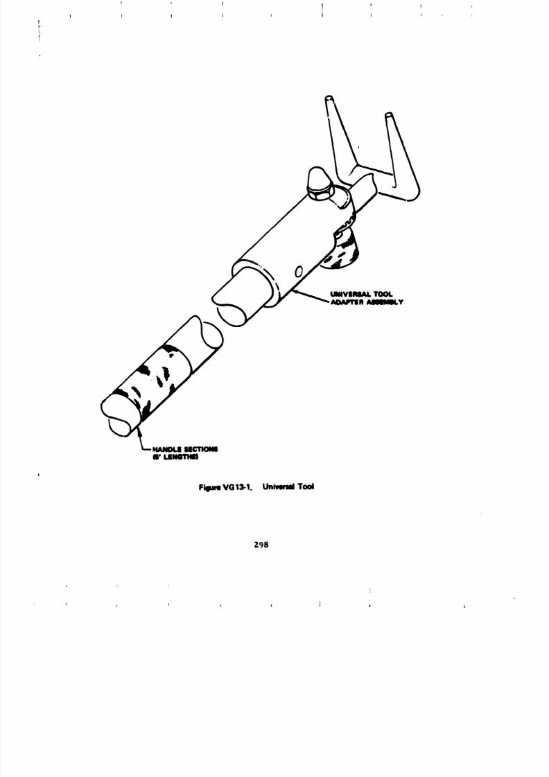
8/8/2019 MSFC Skylab Structures and Mechanical Systems Mission Evaluation
http://slidepdf.com/reader/full/msfc-skylab-structures-and-mechanical-systems-mission-evaluation 315/348
! T t!
Fillum VG13-1. Univeml Tool
298
t
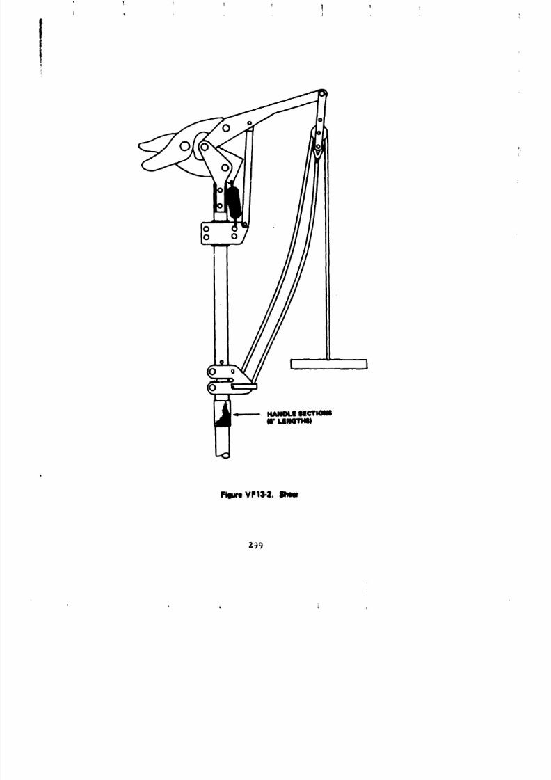
8/8/2019 MSFC Skylab Structures and Mechanical Systems Mission Evaluation
http://slidepdf.com/reader/full/msfc-skylab-structures-and-mechanical-systems-mission-evaluation 316/348
(
L , I
FigumVFl_2. Ilhew
2_9
L L
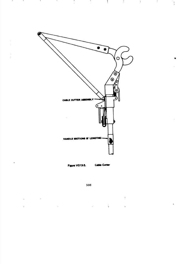
8/8/2019 MSFC Skylab Structures and Mechanical Systems Mission Evaluation
http://slidepdf.com/reader/full/msfc-skylab-structures-and-mechanical-systems-mission-evaluation 317/348
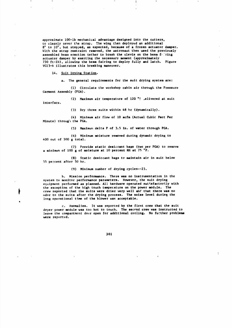
8/8/2019 MSFC Skylab Structures and Mechanical Systems Mission Evaluation
http://slidepdf.com/reader/full/msfc-skylab-structures-and-mechanical-systems-mission-evaluation 318/348
approximate 100-1b mechanical advantage desIRned into the cutters,
to cleanly sever the strap. The wing then deployed an additional
8" to 10", but stopped, as expected, because of a frozen actuator damper.
With the strap restraint removed, the astronaut then used the prevlously
assembled beam erection tether to break the clevis on the beam flaring
actuator damper by exerting the necessary moment (approxlmately
750 ft-lb), a11owln_ the beam fairing to deploy fully amd latch. Figure
VG13-4 illustrates this breaking maneuver.
14. St_it Drying Station.
a. The general requirements for the suit drying system are:
(i) Circulate the workshop cabin air through the Pressure
Garment Assembly (PGA).
(2) Maximum air temperature of 120 "! _ellvered at suitinterface.
(3) Dry three suits within 48 hr (dynamlcally).
(&) Hinlmum air flow of I0 acfm (Actual Cubic Feet Per
Hinute) throug'1 the PGA.
(5) }4axlmu_ delta P of 3.5 in. of water through PGA.
(6) Mlnimum moisture removed during dynamic drying to
400 out of 500 8 total.
(7) Provide static desiccant bars (two per PGA) to remove
a nLtnlmum of 100 g of moisture at 10 percent RH at 75 "F.
(8) Static desiccant bags to maintain air in suit belov
55 pc:cent after 50 hr.
(9) Minlmum number of drying cycles--23.
b. Mission perfonunce. There was no instrumentation in the
system to monitor performance parameters. Hoverer, the sult drying
equlpment performed as planned. All hardware operated satisfactorily with
the exception of the high touch tempexature on the pover module. The
that the suits were dried well anF that there was norew reported very
odor to the suits after the drying process. The noise level durlvg the
long operational time of the blower was acceptable.
c. Anomalies. It was reported by the first crew that the suit
dryer power module was too hot to touch. The second crew was instructed to
leave the compartment door open for additional cooling. No further problems
were reported.
301
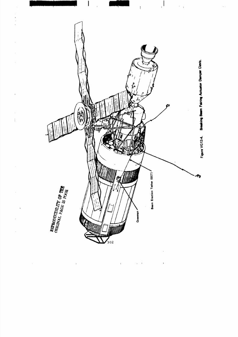
8/8/2019 MSFC Skylab Structures and Mechanical Systems Mission Evaluation
http://slidepdf.com/reader/full/msfc-skylab-structures-and-mechanical-systems-mission-evaluation 319/348
i IT I ] I
/
AI-
v
I--
E|
3O2
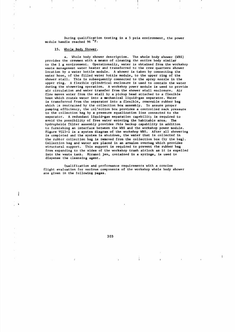
8/8/2019 MSFC Skylab Structures and Mechanical Systems Mission Evaluation
http://slidepdf.com/reader/full/msfc-skylab-structures-and-mechanical-systems-mission-evaluation 320/348
During qualification testing in a 5 psia environment, the powermcdule handle reached 96 °F.
15. Whole Bod2 Shower.
a. Whole body shower description. The whole body shower (WBS)
provides the crewmen with a means of cleaning the entire body similar
to the I g environment. Operatlonally, water is obtained from the workshop
waste management water heater and transferred to the crew quarters shower
location by a water bottle module. A shower is taken by connecting the
water hose, of the filled water bottle module, to the upper ring of the
shower stall. This is subsequently connected to the spray nozzle in the
upper ring. A flexible cylindrical enclosure is used to contain the water
during the showering operation. A workshop power module is used to provide
air circulation and water transfer from the shower stall enclosure. Air
flow moves water from the stall by a pickup head attached to a flexible
hose which routes water into a mechanical liquid-gas separator. Water
is transferred from the separator into a flexible, removable rubber bag
which is restrained by the collection box assembly. To assure proper
pumping efficiency, the collection box provides a controlled oack pressure
to the collection bag by a pressure equalization line connected to the
separator. A redundant liquid-gas separation capabilit} is required to
avoid the possibility of free water entering the habitable area. The
hydrophobic filter assembly provides this backup capability in addition
to furnishing an interface between the WBS and the workshop power module.
Figure VGIS-I is a system diagram of the workshop WBS. After all showering
is completed and the system is shutdown, the water that is collected in
the rubber collection bag is removed from the collection box (by the bag).
Collection bag and water are placed in an armalon overbag which provides
structural support. This support is required to prevent the rubber hag
from expanding to the sides of the workshop trash alrlock as it is expelled
into the waste tank. Miranol jem, contained in a syringe, is used to
dispense the cleansing agent.
Qualification and performance requirements with a concise
flight evaluation for various components of the workshop whole body shower
ale given in the following pages.
303
:
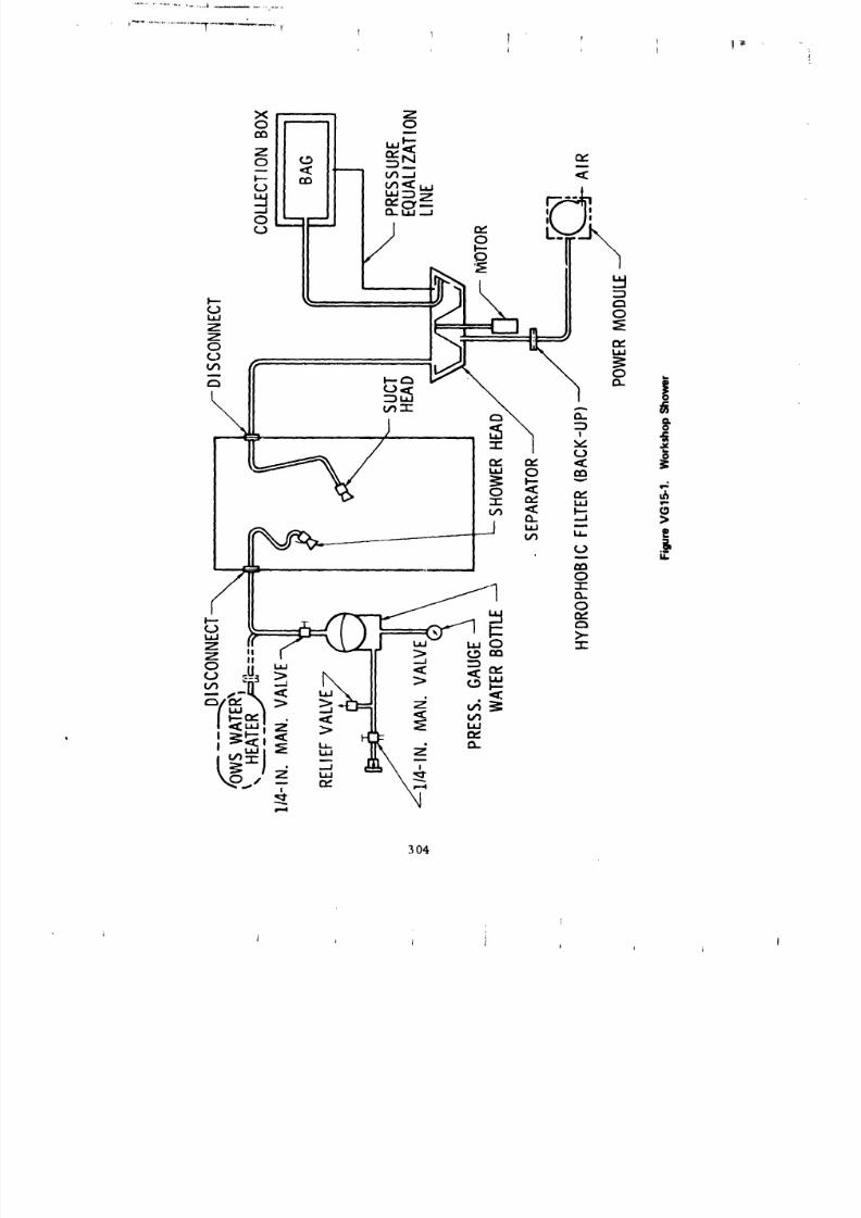
8/8/2019 MSFC Skylab Structures and Mechanical Systems Mission Evaluation
http://slidepdf.com/reader/full/msfc-skylab-structures-and-mechanical-systems-mission-evaluation 321/348
...................................."....... "";......... r T l ! f1
, t , t
304
i
I i i _ ;
I I
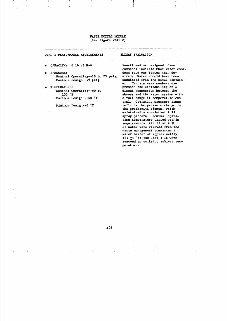
8/8/2019 MSFC Skylab Structures and Mechanical Systems Mission Evaluation
http://slidepdf.com/reader/full/msfc-skylab-structures-and-mechanical-systems-mission-evaluation 322/348
I
WATER BOTTLE MODULE
(See figure VG15-2)
QUAL & PERFORMANCE REQUIREMENTS FLIGHT EVALUATION
• CAPACITY: 6 Ib of H20 Functioned as designed. Crewcomments indicate that water cool-
• PRESSURE: down rate was faster than de-
Nominal Operatlng--lO to 25 pslg sired. Water should have been
Maximum Deslgn--49 psig insulated from the metal contain-er. Certain crew members ex-
• TEMPERATURE: pressed the desirability of :t
Nominal Operatlng--60 to direct connection between the
130 °F shower and the water system with
Maximum Design--160 °F a full range of temperature con-
trol. Operating pressure range
Minimum Deslgn--O °F reflects the pressure change in
the prechar_ed plenum, which
maintained a consistant full
spray pattern. Nominal opera-
ting temperature varied within
requirements: the first 4 Ib
of water were removed from the
waste management compartment
water heater at approximately
127 +3 °F; the last 2 Ib were
removed at workshop ambient tem-
peEat,lre.
305
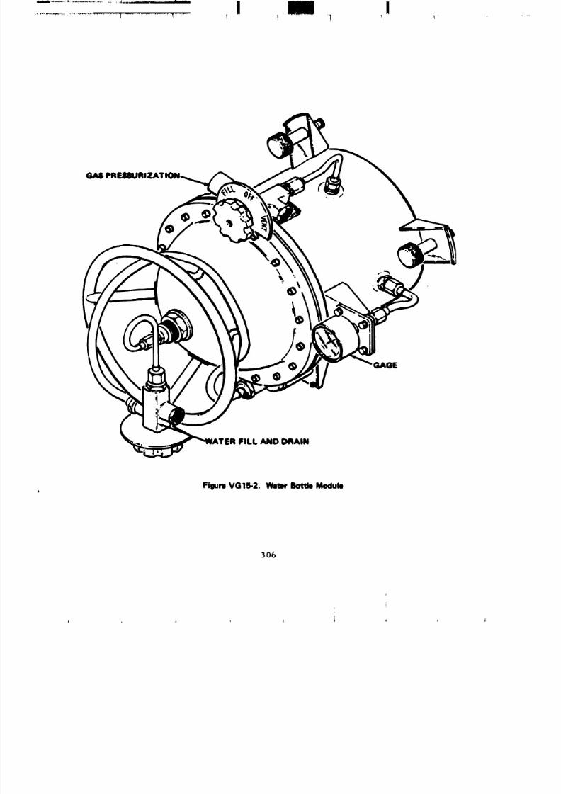
8/8/2019 MSFC Skylab Structures and Mechanical Systems Mission Evaluation
http://slidepdf.com/reader/full/msfc-skylab-structures-and-mechanical-systems-mission-evaluation 323/348
...... , .....................i_... ........... i III !
.......................T............... I ....... ! , 1 _ I
GAS
GAGE
ER FILL AND D4_AIN
FigureVG15-2. WatmrBottleModulo
306
I
8/8/2019 MSFC Skylab Structures and Mechanical Systems Mission Evaluation
http://slidepdf.com/reader/full/msfc-skylab-structures-and-mechanical-systems-mission-evaluation 324/348
] i ......... ,,i_. , J ................. i,i .......... i ,_._.i. .,J ........... ........ _i,l.,,_ .......................... _'i_''ilillllli ...... • .................... 1 ...... i rii. _...... i__
/I ( i _ I i
SHOWER STALL ASSEMBLY
(See figure VG15-3)
QUAL & PERFORMANCE REQUIREMENTS FLIGHT EVALUATION
• COLLAPSIBLE CYLINDER: Collapsible cylinder was used to
reduce launch dynamics problems
Dimensions: 36-in. diamby 74 in. and allow a larger operationalvolume in the habitable area when
Flow Rate and Delta Pressure: the shower was not in use. Dimen-
1.0 in. H20 at i0 scfm slons were defined by human engin-
eering testing and available hard-i LIFE CYCLE: ware and proved acceptable.. Flow
rate and delta Pressure were adequateInstallation and removal--25 to contain the free water in the
Shower Curtain--300 shower stall and maintain the CO 2
level at nominal. Life cycle
testing was more than adequatewith no curtain or latch failures.
The third manned crew complained
of wet walls being cold to the touch
as they moved about to vacuum upthe loose water.
307

8/8/2019 MSFC Skylab Structures and Mechanical Systems Mission Evaluation
http://slidepdf.com/reader/full/msfc-skylab-structures-and-mechanical-systems-mission-evaluation 325/348
I
FigureVG15-3..Whom BodyShowerStall (Operational)
3O8

8/8/2019 MSFC Skylab Structures and Mechanical Systems Mission Evaluation
http://slidepdf.com/reader/full/msfc-skylab-structures-and-mechanical-systems-mission-evaluation 326/348
SHOWER HEAD ASSEMBLY(See figure VGIS-4)
QUAL & PERFORMANCE REQUIREMENTS FLIGHT EVALUATION
• SPRAY PATTERN: Full Cone A full cone spray pattern was
maintained throughout the nominal
• PRESSURE: operating range. Flow rates and
Nominal Operating--lO to 25 pslg the spray Rattern were found to be
very comfortable and deslrabte.
• FLOW RATES: Design cycle llfe proved to be morethan adeq_tate. There were no
1400 ml/mln at 26.2 psl g crew complaints relative to the
850 ml/min at 7.4 pslg shower head.
• LIFE CYCLES: i0,000
309
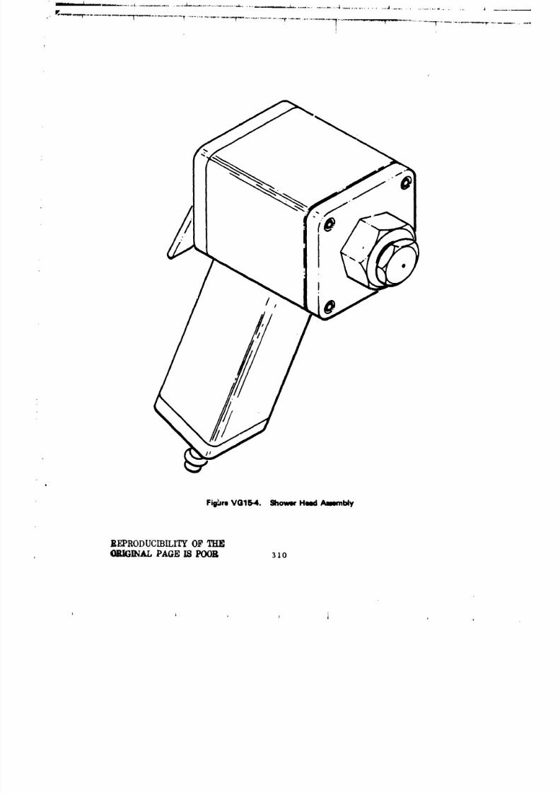
8/8/2019 MSFC Skylab Structures and Mechanical Systems Mission Evaluation
http://slidepdf.com/reader/full/msfc-skylab-structures-and-mechanical-systems-mission-evaluation 327/348
T T!I
Fiil_re VOlli.4. Shower Heed Ajmmbly
REPRODUCIBILITYF THE_AL PAGE IS POOR 31o
8/8/2019 MSFC Skylab Structures and Mechanical Systems Mission Evaluation
http://slidepdf.com/reader/full/msfc-skylab-structures-and-mechanical-systems-mission-evaluation 328/348
. °_
..... |
"_ .3...=. _ ,._..,.-, .....
. . . .. . .. . .. . .. . .. .. _ . . .. . .. . . "" '_" ""_" 1
iI
._ _.__' ,
7
SUCTION HEAD ASSENBLY
_ee figure VG15-5)
QUAL & PERFORMANCEREQUIREMENTS _ICHT EVALUATION
• DELTA P: 1.5 in. H20 at i0 ecfm Pickup efficiency was consideredpoor. Shower stall clanup was
• LIFE CYCLES: 10,000 very time consuming. Higher air
flows will be required to improve
the pickup efficiency significantly
(Higher air flows of 15 to 18 in.
H20 with the required blower
head were not available on Skylab.)
Cycle life of wiper was sufficientas no crew comments were recorded
concerning wiper failure.
!
i'
L311
iL
l
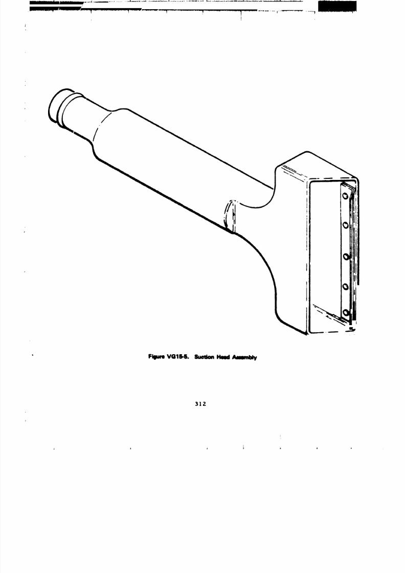
8/8/2019 MSFC Skylab Structures and Mechanical Systems Mission Evaluation
http://slidepdf.com/reader/full/msfc-skylab-structures-and-mechanical-systems-mission-evaluation 329/348
//i
i
F_m VGtS-S.Sum_ Haul
312
8/8/2019 MSFC Skylab Structures and Mechanical Systems Mission Evaluation
http://slidepdf.com/reader/full/msfc-skylab-structures-and-mechanical-systems-mission-evaluation 330/348
I V ! 1 '
!
COLLECTION BOX AND BAG ASSEMBLY
(See figure VC15-6)
QUAL & PER_)RMANCE REQUIREMENTS FLIGHT EVALUATION
• COLLECTION BOX: Contain the The collection box successfully
collection bag; provide 1.O in. H20 contained the collection bag andpressure on the collection bag it maintained approximately +i in.
during liquid gas separation, delta P exterior to interior of the
bag during shower operation. This
• COLLECTION _AC: Cmpsclty: 6.9 Ib delta P was maintained with a bal-
of H20. No visual liquid leakage mnced set of orifices.
• Design Burst: 4 psig Throughout the Skylab mission
the collection bag contained all
• OVER BAG: Provide structural the waste water produced during one
support for the collectlon bag. shower. After three showers were
taken, the three filled, ba.;-over
bag, units were disposed of through
the workshop trash airlock.
The over bag successfully contained
the collection bag sufficiently
to permit operation of the trashairlock.
313
!
' t i _ ,
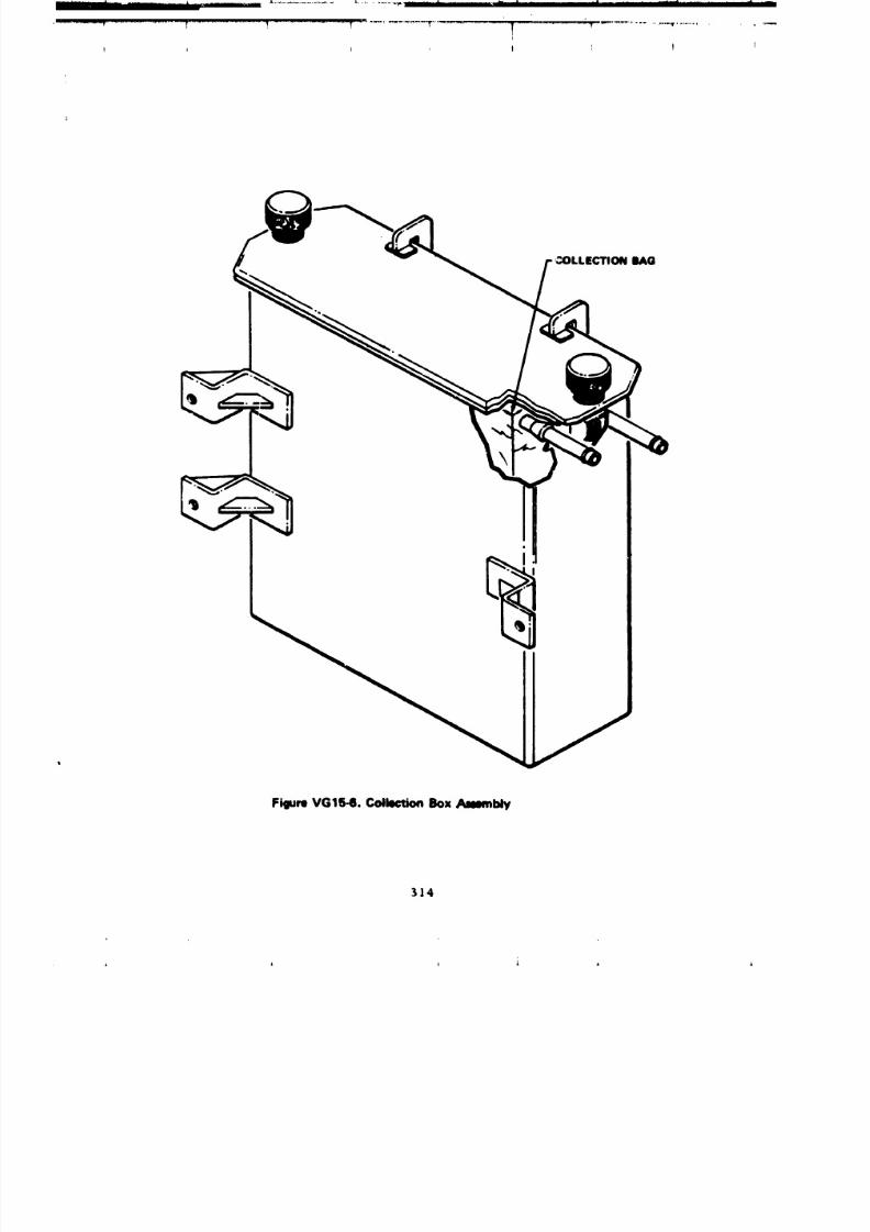
8/8/2019 MSFC Skylab Structures and Mechanical Systems Mission Evaluation
http://slidepdf.com/reader/full/msfc-skylab-structures-and-mechanical-systems-mission-evaluation 331/348
... II .... III I J'..............................
i
_)LLECTION BAG
Figure VG15-6. Collection Box _bty
314
8/8/2019 MSFC Skylab Structures and Mechanical Systems Mission Evaluation
http://slidepdf.com/reader/full/msfc-skylab-structures-and-mechanical-systems-mission-evaluation 332/348
mm ................. _ ..........
,,,_'._.'" ....... "_ _"'_"_ ..... T................. _ .................... _ .... _ . ........ _"
LIqUID-GAS SEPARATOR
(Sea figure VCI_-7)
i _... m • .|i _ J| m |i
QUAL & PERFOR,q_ICE RF_UIRI94DTS FLI, _.r EVALUATION
• PUMPING RATE: 1100,.l/ain of The unit performed ms designed
H..O. Delta P: 5.0 in. H20 at unti1 day 77 of the third manned1_ scfm. phase at 1856 CDT. At that time
the _rew reported the shower
• RPN: 250 at 28 Vdc power uodule was iaopersc£ve. This
condition appeared co be the resultof the water In the nodule. Based
on this 8ssunptton, failure of the
l_quld-gas separator was probable.Crew connents Indicated that _he
shover soap supply was depleted
and that they replaced It rich
Nutrsgena soap. The reduced
pumping capability caused by
high sudsing and plussin 8
probably resulted in waste water
being carried ou. the 81r outlet
of the separator.
315

8/8/2019 MSFC Skylab Structures and Mechanical Systems Mission Evaluation
http://slidepdf.com/reader/full/msfc-skylab-structures-and-mechanical-systems-mission-evaluation 333/348
OUTLET
EQUALIZATION
AIR OUTLE
'_..
SHOWER INLE1
FigureVG15-7. Centrifupl Separator
316
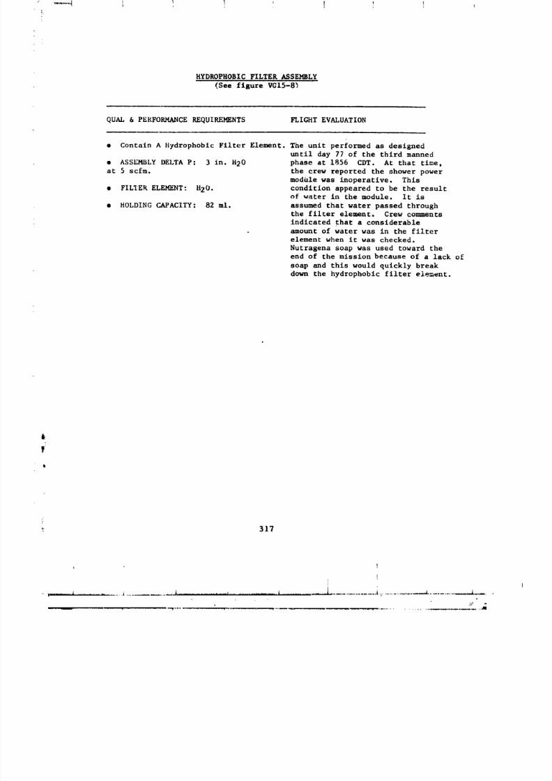
8/8/2019 MSFC Skylab Structures and Mechanical Systems Mission Evaluation
http://slidepdf.com/reader/full/msfc-skylab-structures-and-mechanical-systems-mission-evaluation 334/348
HYDROPHOBIC FILTER ASSEMBLY
(See figure VGI5-8_
QUAL & PERFORMANCE REQUIREMENTS FLIGHT EVALUATION
• Contain A Hydrophobic Filter Element. The unit performed as designed
until day 77 of the third manned
• ASSEMBLY DELTA P: 3 in. H20 phase at 1856 CDT. At that time,
at 5 scfm. the crew reported the shower power
module was inoperative. This
• FILLER ELEMENT: I120. condition appeared to be the resultof water in the module. It is
• HOLDING CAPACITY: 82 ml. assumed that water passed throughthe filter element. Crew comments
indicated that a considerableamount of water was in the filter
element when it was checked.
Nutragena soap was used toward the
end of the mission because of a lack of
soap and this would quickly break
down the hydrophobic filter element.
317
i
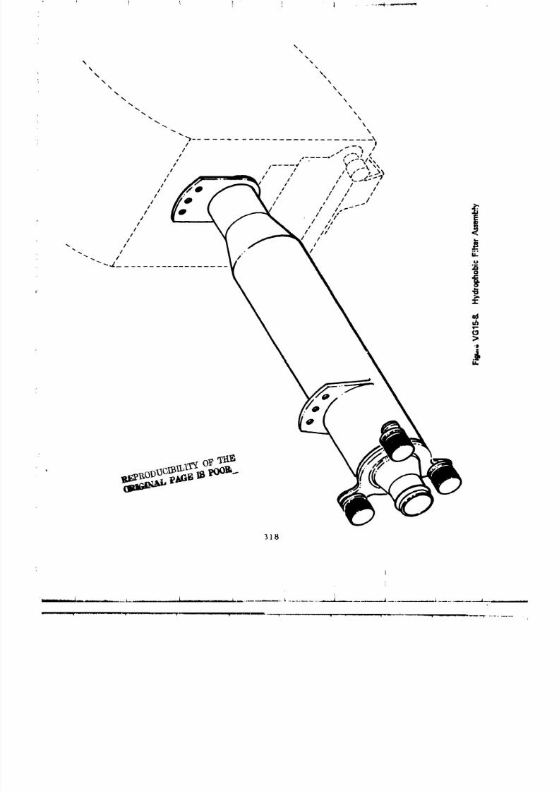
8/8/2019 MSFC Skylab Structures and Mechanical Systems Mission Evaluation
http://slidepdf.com/reader/full/msfc-skylab-structures-and-mechanical-systems-mission-evaluation 335/348
I
...._.. ......_..... l......................... _ _ ......... i ................... _ .... _ ............... _.............. ___......
8/8/2019 MSFC Skylab Structures and Mechanical Systems Mission Evaluation
http://slidepdf.com/reader/full/msfc-skylab-structures-and-mechanical-systems-mission-evaluation 336/348
SOAP DISPENSER & SOJ_P
QUAL & PERFORMANCE REQUIREMENTS FLIGHT EVALUATION
• DISPENSER: Crewmen reported soap shortages.
Capacity: 64 ml Leakage was never reported through-
Pressure: out the Skylab mission. The
Normal Operating - 0-12 pslg cleansing agent (Miranol Jem)
Proof - 18 psig performed as required. The odorwas not desirable and crew comments
• LEAKAGE: 1.0 x 10⁻² sccs at reflected this opinion. In12 psig preflight development, adverse,
cleansing agent comments were
• SOAP: received only when greater quantitiesNonbacterlacidal thati planned were used. Crew
Nonwetting of Hydrophobic comments reflect that they ran out
Membranes of soap, which is indicative that
Approval of The Food And Drug larger portions than planned wereAdministration used.
Low Sudsing "
319
: , , j J , , ,
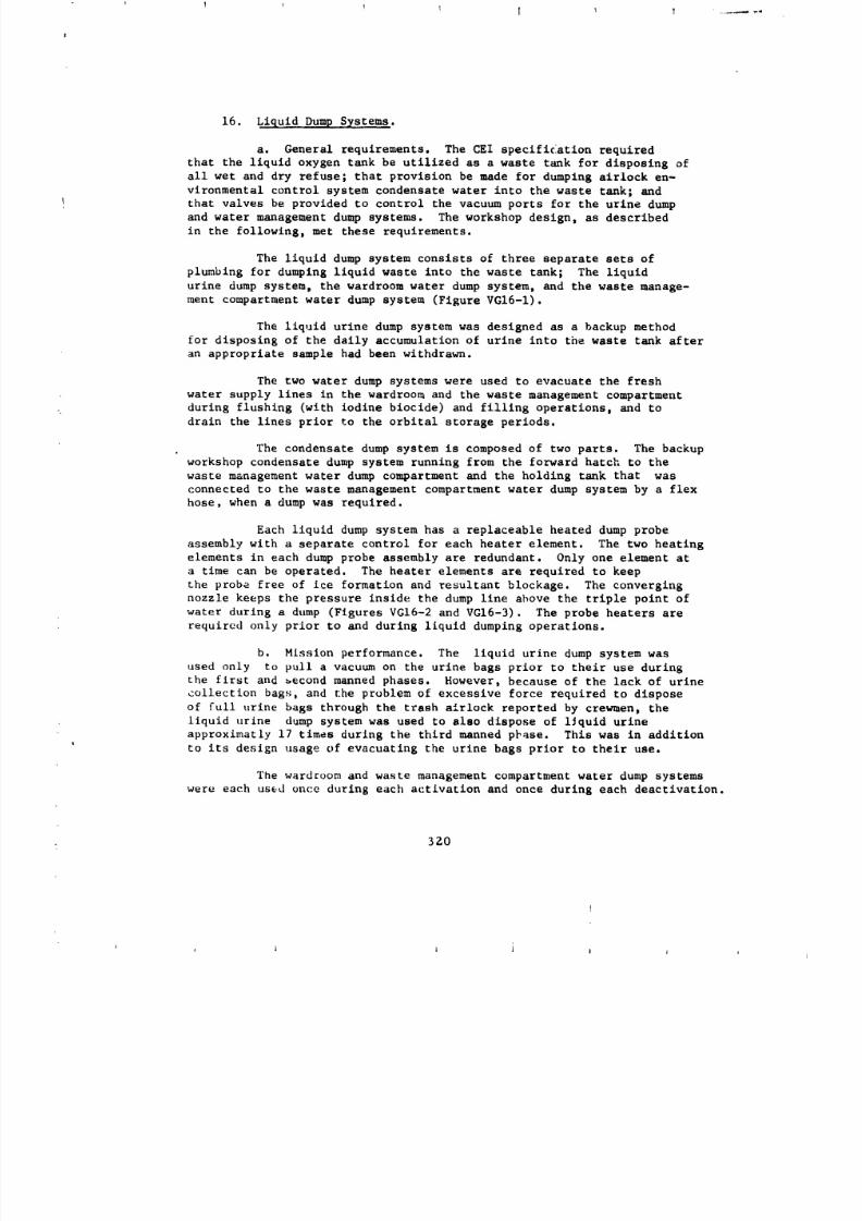
8/8/2019 MSFC Skylab Structures and Mechanical Systems Mission Evaluation
http://slidepdf.com/reader/full/msfc-skylab-structures-and-mechanical-systems-mission-evaluation 337/348
16. Liquid Dump Systems.
a. General requirements. The CEI specification required
that the liquid oxygen tank be utilized as a waste tank for disposing of
all wet and dry refuse; that provision be made for dumping airlock en-vironmental control system condensate water into the waste tank; and
that valves be provided to control the vacuum ports for the urine dump
and water management dump systems. The workshop design, as described
in the following, met these requirements.
The liquid dump system consists of three separate sets of
plumbing for dumping liquid waste into the waste tank; The liquid
urine dump system, the wardroom water dump system, and the waste manage-
ment compartment water dump system (Figure VGI6-1).
The liquid urine dump system was designed as a backup method
for disposing of the daily accumulation of urine into the waste tank after
an appropriate sample had been withdrawn.
The two water dump systems were used to evacuate the fresh
water supply lines in the wardroom and the waste management compartment
during flushing (with iodine biocide) and filling operations, and to
drain the lines prior to the orbital storage periods.
The condensate dump system is composed of two parts. The backup
workshop condensate dump system running from the forward hatch to the
waste management water dump compartment and the holding tank that was
connected to the waste management compartment water dump system by a flex
hose, when a dump was required.
Each liquid dump system has a replaceable heated dump probe
assembly with a separate control for each heater element. The two heatingelements in each dump probe assembly are redundant. Only one element at
a time can be operated. The heater elements are required to keep
the probe free of ice formation and resultant blockage. The converging
nozzle keeps the pressure inside the dump line above the triple point of
water during a dump (Figures VGI6-2 and VGI6-3). The probe heaters are
required only prior to and during liquid dumping operations.
b. Mlssion performance. The liquid urine dump system was
used only to pull a vacuum on the urine bags prior to their use during
the first and _econd manned phases. However, because of the lack of urine
collection bags, and the problem of excessive force required to dispose
of full urine bags through the trash airloek reported by crewmen, the
liquid urine dump system was used to also dispose of liquid urine
approximatly 17 times during the third manned phase. This was in addition
to its design usage of evacuating the urine bags prior to their use.
The wardroom and waste management compartment water dump systems
were each used once during each activation and once during each deactivation.
370
J t J A i ! j j
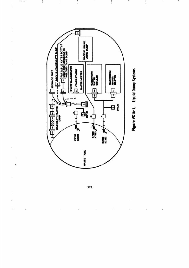
8/8/2019 MSFC Skylab Structures and Mechanical Systems Mission Evaluation
http://slidepdf.com/reader/full/msfc-skylab-structures-and-mechanical-systems-mission-evaluation 338/348
M
I321
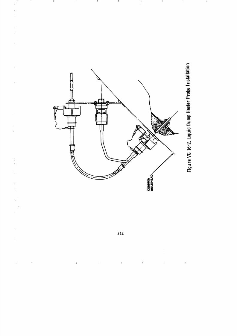
8/8/2019 MSFC Skylab Structures and Mechanical Systems Mission Evaluation
http://slidepdf.com/reader/full/msfc-skylab-structures-and-mechanical-systems-mission-evaluation 339/348
3ZZ
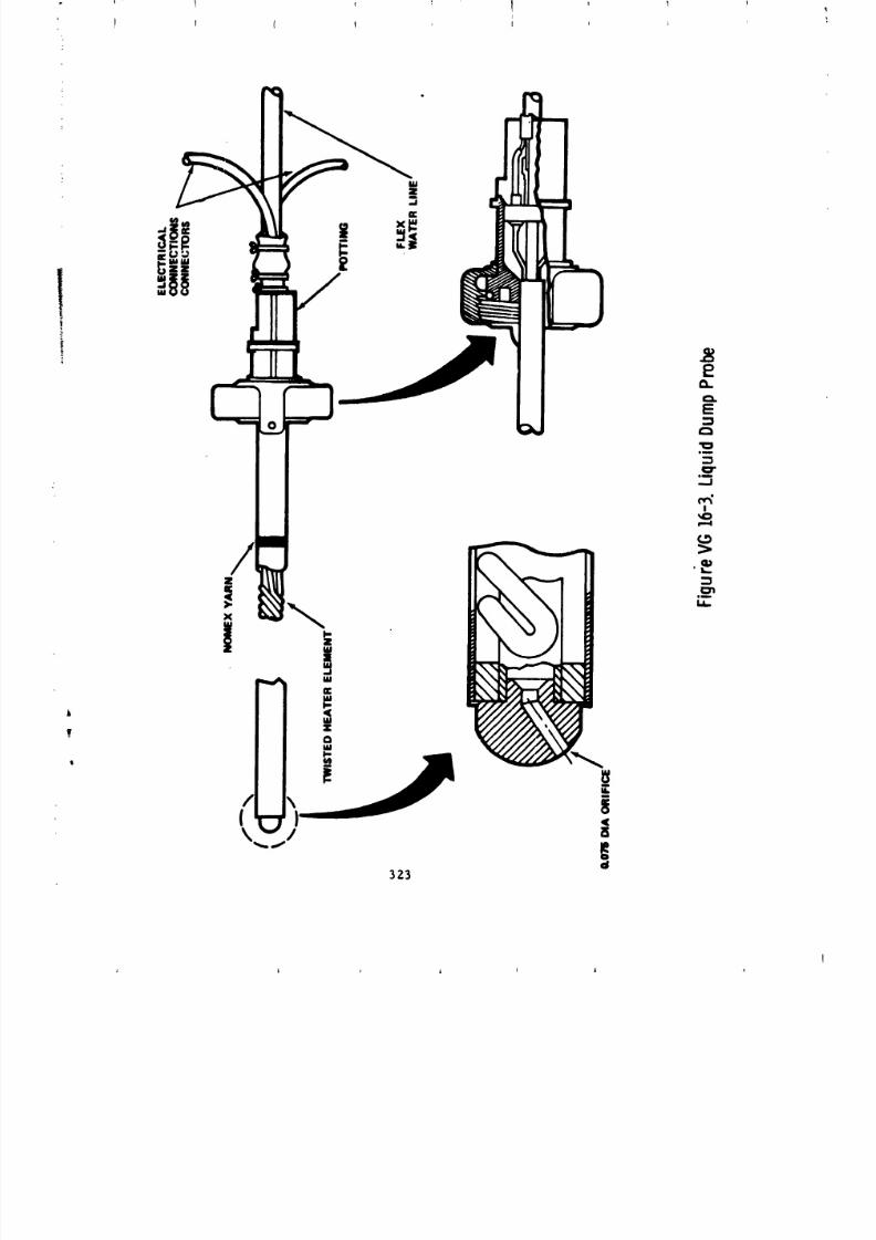
8/8/2019 MSFC Skylab Structures and Mechanical Systems Mission Evaluation
http://slidepdf.com/reader/full/msfc-skylab-structures-and-mechanical-systems-mission-evaluation 340/348
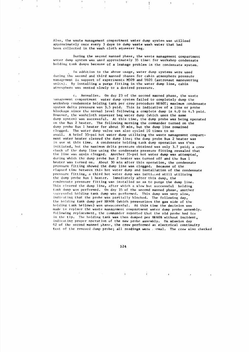
8/8/2019 MSFC Skylab Structures and Mechanical Systems Mission Evaluation
http://slidepdf.com/reader/full/msfc-skylab-structures-and-mechanical-systems-mission-evaluation 341/348
Also, the waste management compartment water dump system was utilized
approximately once every 3 days to dump waste wash water that had
been collected in the wash cloth squeezer bag.
During the second manned phase, the waste management compartment
water dump system was used approximately 35 times for workshop condensate
holding tank dumps because of a leakage problem in the condensate system.
In addition to the above usage, water dump systems were used
durin_ the second and third manned phases for cabin atmosphere pressure
management i_l support of experiments M509 and TO20 (astronaut maneuvering
units). By installing a purge fitting in the water dump llne, cabin
atrno_phere was vented slowly to a desired pressure.
c. Anomalies. On day 23 of the second manned phase, the waste
nana_ement compartment water dump system failed to completely dump the
workshop condensate holding tank per crew procedure HK6OT; maximum condensate
system delta pressure was 3.5 psid. This is indicative of a llne or probe
blockage since the normal level following a complete dump is 4.0 to 4.5 psid.
llowever, the washcloth squeezer bag water dump (which uses the same
dump system) was successful. At this time, the dump probe was being operated
on the Bus 2 heater. The following morning the commander turned on the
dump probe Bus i heater for about 30 min, but the dump llne remained
clogged. The water dump valve was also cycled IC times to no
avail. A brief 35-psl hot water dump utilizing the waste management compart-
ment water heater cleared the dump line; the dump probe Bus 2 heater was
in use at this time. A condensate holding tank dump operation was then
initiated, but the maximum delta pressure obtained was only 3.7 psid; a crew
check of the dump line using the condensate pressure fitting revealed that
the llne was aEain clop.ged. Another 35-psi hot water dump was attempted,
durinK which the dump probe Bus 2 heater was turned off and the Bus iheater was turned on. About 30 sin after this operation, the condensate
pressure fitting showed the dump line was clogged. Because of the
elapsed tlmu between thls hot water dump and installation of the condensate
pressure fitting, a third hot water dump was inlti_ed still utilizing
the dump probe Bus I heater. Immediately after this dump, the
c¢)ndensate pressure fitting was installed so as to purge the dump line.
This cleared the dump line, after which a slow but successful holding
t;mk dump was performed. On day 35 of the second manned phase, another
_,ucce_.qful l,olding tank dump was performed, This dump was very slow,
indicating, that the probe was partially blocked. The followinK day,
the holdin_ tank dump per HK6OB (which pressurizes the gas side of the
boldin_ tank bellows) was unsuccessful. At this time the decision was
made, to replace the waste management compartment water dump probe assembly.
Following replacement, the commander reported that the old probe had ice
in the tip. The ho[dinK tank was then dumped per HK60B wlthout incident,
indicatln?, proper operation of the new probe assembly. On mission day
42 of the second manned phas,_, the crew performed an electrical continuity
test of the removed dump probe; all readings were , _rmal. The crew also checked
324
L A _ l
8/8/2019 MSFC Skylab Structures and Mechanical Systems Mission Evaluation
http://slidepdf.com/reader/full/msfc-skylab-structures-and-mechanical-systems-mission-evaluation 342/348
I I ! 1 I l
i
the probe for contamination by inserting and withdrawing a length of safety
wire, and by blowing through the probe; no contamination was found and the
probe was returned to stowage for use as a future spare.
Five potential mechanisms of ice blockage formation were identified
based on previous ground test experience: internal contamination; ice
buildup on probe tip; ice building back along normal flow path from waste
tank wall; and ice buildup aggravated by high pressure dump (Figure VGI6-4).
Exact cause of probe freezup is not known; however, all subsequent water
dumps through the new probe were successful. On day 51 of the third manned
phase, the crew reported a problem in the liquid urine dump system.
_le attempting to evacuate a urine bag following a liquid urine dump,
no flow was observed through the system. The dump heater probe was operating
as evidenced by the indicator lights. The crew left the heaters on for
several hours and later that day flow through the system resumed. No
further problems were encountered during the remainder of the mission.
Because of the possibility of blockage by a small piece of undissolved
boric acid tablet, tests were conducted. The testing showed that althoughtemporary flow stoppages lasting from 5 to 9 sec were observed during the
two 6 test dumps, these stoppages had been seen during development
and acceptance testing and were not considered unusual or detrimental
to system performance. TDe most ]ikely cause of the blockage was a buildup
of ice on the probe that required a longer than normal heater-on time.
This assumption is supported by the fact that no further problems
were reported. The crew also stated that they left the liquid urine dump
heater probe on for the rest of the mission to ensure that no additional
problems would occur.
d. Recommendations. The probe concept is recommended for
future systems of this type. Although some problems were experienced
indicating need for further _mprovements, general success of this conceptwas the result of emphasis placed on system development and testing under
conditions that closely simulated the flight environment.
17. Vent System
a. Habitability area
(I) General requirements.
(a) The tank shall have the capability of being
vented nonprc,pulsively to space environment.
(b) Venting shall be terminated by _entrol fromthe workshop switch selector.
(c) Solenoid valves shall be installed in the
habitation area vent system to provide the capability to vent the habitation
area by a signal from the airlock on conunand from the ground.
325
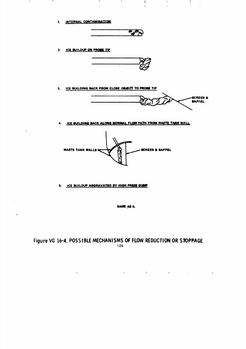
8/8/2019 MSFC Skylab Structures and Mechanical Systems Mission Evaluation
http://slidepdf.com/reader/full/msfc-skylab-structures-and-mechanical-systems-mission-evaluation 343/348
I T _ ti , !
1. INTERNAL CQqTAMqNATION
2. ic4WILOUem,__.glL_
3. ICE BUILDING BACKPROM CLOSEOllJ_C_rTO PlqOll TIPi
_/-ICREEN &
4. iCl_DUILDII_ BACKA_.ONQNORMA_ FLI_ PATH FROMWAITE TANKWALle
WASTETANK WALLI ICREEN & RAFe|L
5. ICE IUILIXJF AGGRAVATED BY HIGH Plll_l
IAII AS 4.
Figure VG16-4.POSSIBLEMECHANISMSOFFLOWREDUCTIONORSTOPPAGE_26
8/8/2019 MSFC Skylab Structures and Mechanical Systems Mission Evaluation
http://slidepdf.com/reader/full/msfc-skylab-structures-and-mechanical-systems-mission-evaluation 344/348
! ! I ! !
l
(d) A sealing device shall be provided for the LH 2vent tank outlets to minimize leakage.
(2) Mission performance. The workshop pneumatic vent
valves operated normally, as evidenced by the nominal blowdown of the
habitation area following launch. The pneumatic vent valves were inoperative
during the rest of the Skylab mission.
Because of the loss of the meteoroid shield during launch
phase, and the subsequent high temperatures experienced in the workshop,
the cl.uster was purged of any potential toxic outgassing by alternate
pressurizing and venting, five times, prior to crew arrival, Solenoid
vent valve opecatlon was normal throughout these operations, except
at the conclusion of the final vent, when the talkback for valves #1 and
#3 did not indicate closed (146:02:02). Since valves #2 and #4 did
indicate closed the only problem was apparent loss of redundancy. The
probable cause was the talkback switch on the valve. Subsequent operation
of the valves on all three manned phases was normal with proper valvetalkback.
Each post-occupation vent was accomplished without ex-
penditure of thruster a tltude control subsystem propellant, thus verifying
that the vent system was nonpropulsive.
The pneumatic vent port sealing device was installed
during the first crew visit inlnediately after entering the workshop
with no repc)rted problems. The _olenold vent port sealing device was
not installed because of the low cluster leakage rate and the desire
to simplify emergency egress procedures.
(3) Anomalies. Two anomalies were associated with tilesolenoid vent system prior to the flzst manned phase activation. During
the final vent cycles of the potentially toxic cluster gases prior to
the first manned phase, the vent rate was slower than predicted. In
addition, at the end of the cycle, solenoid vent valves #I and #3 failed
to indicate closed after the close command wes sent. Valves #2 and #4
did close properly and allowed the cluster to be pressurized normally.
The probable cause of the slow vent rate was the presence of debris
in the system. The first crew verified the existence of debris in tb.e
solenoid vent port inlet filter and subsequently cleaned the filter
per an unscheduled maintenance procedure.
Troubleshooting the failure of valves #I and #3
to indicate closed was delayed until mission day 18 of the first manned
phase. At that time all four solenoid valves were commanded open,
and the crew reported flow. Then valves #I and #3 were commanded closed;
and the valves responded normally; valves #2 and #4 were then closed.
Exact cause of the ,-omaly is unknown, but the problem failure mode
was particulate contamination. Subsequent operation of the solenoidvent w_ives was normal.
32.7
I I l l
8/8/2019 MSFC Skylab Structures and Mechanical Systems Mission Evaluation
http://slidepdf.com/reader/full/msfc-skylab-structures-and-mechanical-systems-mission-evaluation 345/348
(4) Recommendations. the value of a quad redundant
system was evident in the anomaly with the solenoid vent system. Future
design should carefully examine the factors of reliability versus complexity
involved to determine the extent of redundancy r_qulred.
The use of filters at the inlet to vents is required to
protect systems from debris that cannot be detected and removed prior
to the vent operation. Each Skylab crew reported some debris £n the
solenoid vent port inlet filter following venting,
b. Waste tank.
(I) General requirements.
(a) A nonpropulslve vent shall be provided for
venting the LOX tank.
(b) The waste tank (LOX tank) shall be pressurized
at launch with nitrogen gas to stabilize the structural shell during
launch and flight. The internal pressure shall be maintained within
a 22 to 26 psia operating range during launch and ascent. The tank shall
have the capability of being vented to space environment.
(c) The waste tank shall be continuously vented
in orbit. '[he waste tank vent shall remain open after initial venting
(d) The LOX tank shall be used as a waste tank
for disposing of all wet and dry materials and refuse collected in habitable
areas internal to orbital assembly. Provisions shall be made for providing
waste tank screen filters for limiting of ice particles and contaminants,
in the order of I0 microns, from being vented through the waste tank vents.
(2) Mission performance. Waste tank vent system operation
was normal throughout all three manned phase missions. Except for
pressure spikes associated with water dumps during activation and deactivation
of SL-2 and during the 35 psi water dumps f.rformed in troubleshooting
the waste management compartment water dump probe, waste tank pressure
was maintalned well below the triple point of water (0.29 psia). The high
waste tank pressure was apparently due to a higher than expected rate
,,f sublimation of the ice formed during the liquid dumps, but no adverse
effects were observed because of this high pressure.
All flight data indicated that the waste tank system,
consisting of filter screens and a nunpropulsive vent, was complet_ly
effective in uruvidlng for disposal of liquid and solid waste materials
outside the habttatlon area without interfering with optical experlmentsor impuslng a load on the attitudt: control system. Discussions with MSFC
c.untamlnath_n _G personnel have indicated that no traces of waste tank
L.ffluents were uncovered in any of their experiments. Evaluatlcn of the
attitude and pointhlg control system data shows no reasurable unbalanced
vt.nting, cvcn during the largest liquid dumps into the waste tank.
,
8/8/2019 MSFC Skylab Structures and Mechanical Systems Mission Evaluation
http://slidepdf.com/reader/full/msfc-skylab-structures-and-mechanical-systems-mission-evaluation 346/348
No anomalies or problems were experienced with the wastetank vents or screens.
18. Vacuum Support System.
a. General requirements. General requirements for the vacuum
support system are:
(1) Vacuum outlet system shall provide a valve to control
the vacuum port for the waste processor and refrigeration pump enclosure.
(2) Provide a pressure of 2.82 psia at a flow rate of 0.111
lb/min at the M092 lower body negative pressure device (LBNPD) Interface.
(3) Provide a pressure of 10-5 torr at a volume flow
rate of ¢7.4 liter/sec at the MIT1 metabolic analyzer vacuum line interface.
b. Mission performance. The waste processor vacuum line shutoff
valve was cycled dace during each manned phase (open on activation and
closed on deactivation). The refrige.ation pump et;closurt hand valve was
left open throughout the three mantled phases. The experiment vacuum support
system provided an adequate vacuum for operation of the LBNPn and the
metabolic analyzer during the three manned phases• The v_cuum lines saw
almost dally asage from experiments M092 and MlYl. The LBNPD vacuum vent
hand valve was cycled once during each manned phase (open on activation and
closed on deactivation).
c. _1omalles. There were no reported hardware problems associated
with the vacuum support system.
Because of the loss of the meteoroid shield during the first unnmnned
launch ph:me, overboard venting through the LBNPD vacuum line tended
tc_ be propulsive, causing momentum buildup that required careful scheduling
of LBNI'D operations• In order to simtllfy the scheduling operations,
two adaptrrs were made and flown on the third manned phase. These adapters
_Ilowed the vrew to ccnnect the I.BN!'r) vacuum line to the waste tank by
using the unused, onboard hoses (Figure VG18-1). This approach a_ _owed
I.ttNPD ga_ to be vented, nonpropulslvely, through the waste tank vents.
_o l,roblems were reported by the crew in performing these hardware modifications
or in the use of the equipment.
19. Pneumatic System.
a. G_neral requirements. The pneumatic system provides actuating
pressure, on co_aand, to the systems listed below within an appropriate period
after lift-off of the ttr_t unmonm,d phase. The pneumatic system loading
pressure band is 390 to 5 psia. The minimum actuation pressures fortim vart,ms functions ere:
3 _')
1
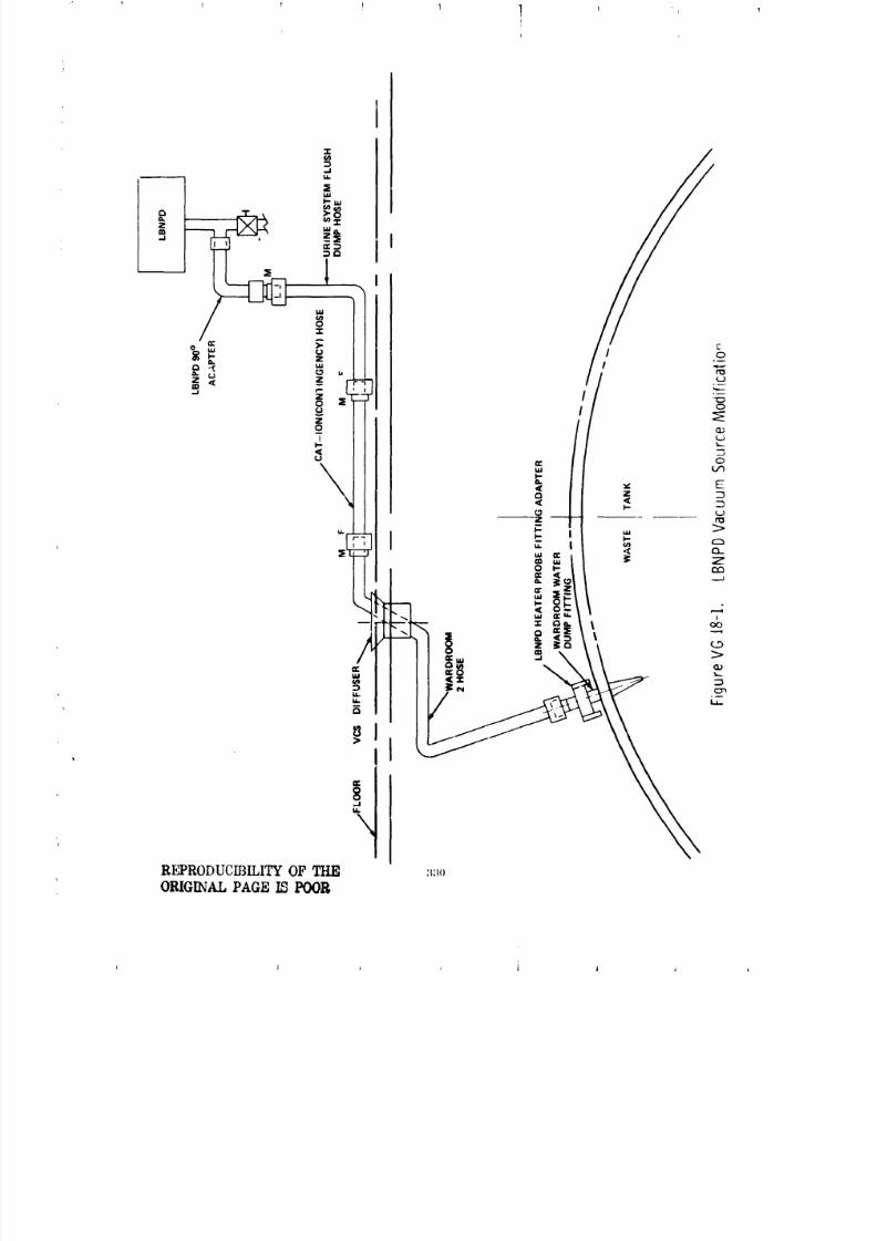
8/8/2019 MSFC Skylab Structures and Mechanical Systems Mission Evaluation
http://slidepdf.com/reader/full/msfc-skylab-structures-and-mechanical-systems-mission-evaluation 347/348
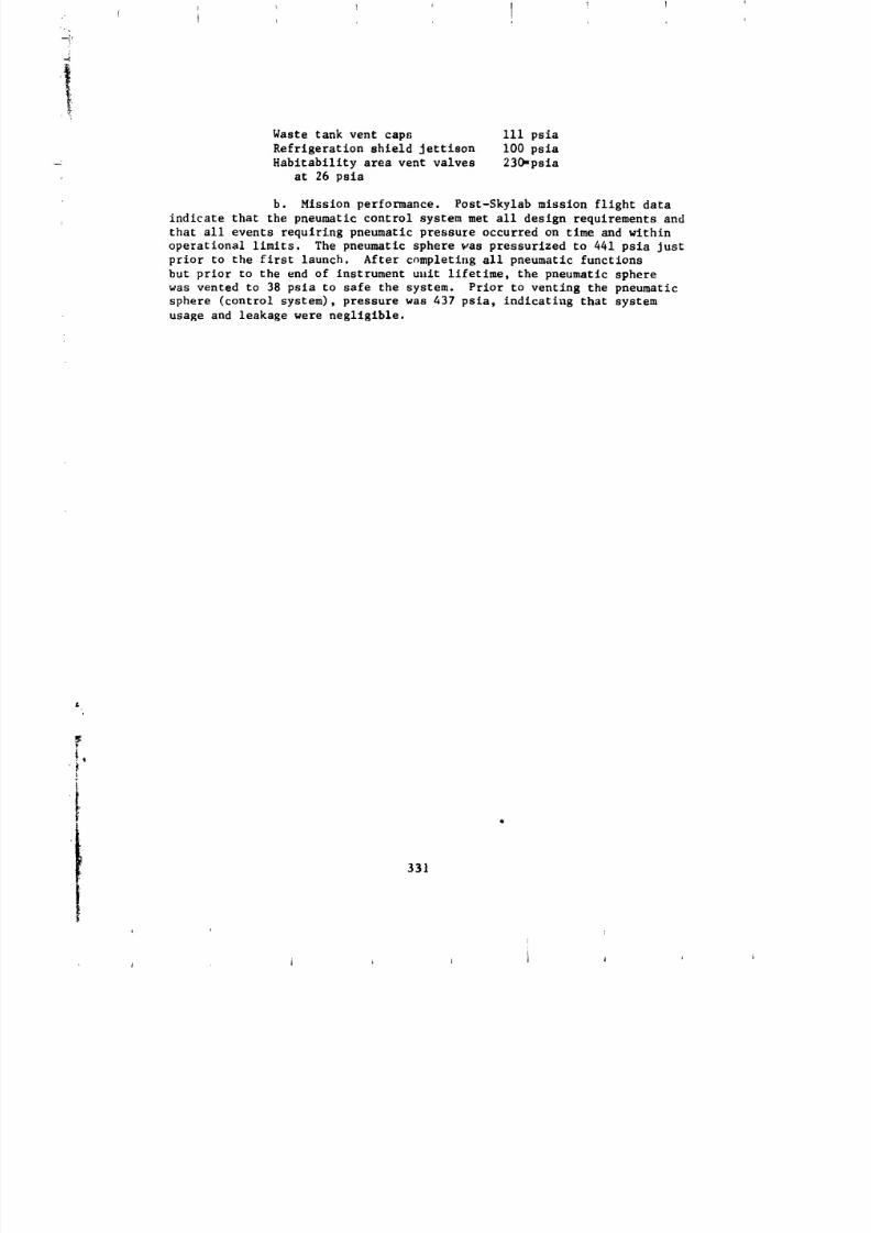
8/8/2019 MSFC Skylab Structures and Mechanical Systems Mission Evaluation
http://slidepdf.com/reader/full/msfc-skylab-structures-and-mechanical-systems-mission-evaluation 348/348
I I ! I ! 1
Waste tank vent caps iii psia
Refrigeration shield Jettison I00 psia
Habitability area vent valves 230-psia
at 26 psia
b. Mission performance. Post-Skylab mission flight data
indicate that the pneumatic control system met all design requirements and
that all events requiring pneumatic pressure occurred on time and within
operational limits. The pneumatic sphere was pressurized to 441 psia just
prior to the first launch. After completing all pneumatic functions
but prior to the end of instrument ullitlifetime, the pneumatic sphere
was vented to 38 psia to safe the system. Prior to venting the pneumatic
sphere (control system), pressure was 437 psia, indicating that system
usage and leakage were negligible.
331