Embed Size (px)
Citation preview
Ericssonwide Internal TECHN PRODUCT DESCR
Prepared (also subject responsible if other) No.
ETL/G/S Henry Gonzalez 2/221 02-ZAP 701 21/2 Approved Checked Date Rev Reference
ETL/G/S Karl-Eric K Malberg 30/08/2005 A
OMS 3260
Product Description
Marconi is the original manufacturer of this product. Ericsson and Marconi have had a close relationship since 1995. The Ericsson Optical Network is a transport network portfolio provided in conjunction with Marconi. It includes SDH and DWDM NE’s and a common NMS system. The portfolio is broad and complete.

OMS3260SDH/OTH 40GB/S MULTIPLEXER
Product Description
Issue E

Product Description OMS3260
Page 2 of 47 Copyright – Refer to Page 2 Issue E
Document code:Date of issue:Issue:Comments:
4on-pd000028-e9 August 2004E
Marconi Communications Ltd. and the Marconi logo are trademarks of Marconi.
This is an unpublished work, the copyright in which vests in Marconi Communications Limited, Marconi Communications SpA andMarconi Communications GmbH. All rights reserved. The work contains information confidential to the above companies and allsuch information is supplied without liability for errors or omissions. No part may be reproduced, disclosed or used except asauthorized by contract or other written permission. The copyright and the foregoing restriction on reproduction extend to all media inwhich the information may be embodied.
The above companies have used all reasonable endeavors to ensure that the information contained in this work is accurate at itsdate of issue, but reserves the right to make changes, in good faith, to such information from time to time, whether by way ofcorrection or meet market requirements or otherwise.
Marconi Communications Ltd.,New Century Park,PO Box 53, Coventry CV3 1HJ,EnglandTelephone: +44 (0)24 7656 2000Fax: +44 (0)24 7656 7000Telex: 31361 MARCOV
Marconi Communications GmbHGerberstraße 3371522 BacknangGermanyTelephone: +49 (0) 71 91 13 - 0Fax: +49 (0) 71 91 13 - 32 12
Marconi Communications SpA,1A, via Negrone 16153,Genova, Cornigliano,Italy.Telephone: +39–010–60021Fax: +39–010–6501897

OMS3260 Product Description
Issue E Copyright – Refer to Page 2 Page 3 of 47
TABLE OF CONTENTS
List of Abbreviations .............................................................................................................. 6
1 Introduction.............................................................................................................. 91.1 SDH Hierarchy......................................................................................................... 91.2 OTN Hierarchy....................................................................................................... 112 Equipment Functions and Architecture .................................................................. 122.1 General Diagram.................................................................................................... 122.1.1 Communication/Controller Subsystem ................................................................... 132.1.2 HO-VC/ODU Switching Subsystem........................................................................ 132.1.3 LO-VC Switching Subsystem ................................................................................. 132.1.4 Configuration ......................................................................................................... 132.2 Types of Ports........................................................................................................ 182.3 Electrical Interfaces Characteristics ....................................................................... 192.4 Optical Interfaces Characteristics........................................................................... 192.4.1 SDH Multirate Card................................................................................................ 222.4.2 Gigabit Ethernet Card ............................................................................................ 232.4.3 Multi-Protocol Data card......................................................................................... 242.4.4 Aggregation Data card ........................................................................................... 252.4.4.1 L2 transport ....................................................................................................... 25
2.4.4.2 L2 switching:...................................................................................................... 262.4.5 OTM cards ............................................................................................................. 273 Mapping & multiplexing functions .......................................................................... 293.1 Connectivity ........................................................................................................... 294 Network Applications ............................................................................................. 31
5 Equipment Structure.............................................................................................. 335.1 Mechanical Structure ............................................................................................. 336 Alarms ................................................................................................................... 34
7 Equipment Protection ............................................................................................ 35
8 Network Protection ................................................................................................ 368.1 MSP protection ...................................................................................................... 368.2 MS-SPRing Protection ........................................................................................... 368.3 Ring Interworking Protection .................................................................................. 388.4 OTN Protection ...................................................................................................... 388.5 OS Restoration ...................................................................................................... 398.6 Fast Restoration..................................................................................................... 399 AUTOMATIC SWITCHING TRANSPORT NETWORK with OMS3260 .................. 40
10 Performance Monitoring and Management ............................................................ 41
11 Equipment Management........................................................................................ 42
12 Services ................................................................................................................ 43

Product Description OMS3260
Page 4 of 47 Copyright – Refer to Page 2 Issue E
13 General operating features.....................................................................................4413.1 Equipment Use.......................................................................................................4413.2 Plug-in Unit Handling..............................................................................................4413.3 Fault Management (Self Diagnostic).......................................................................4413.4 Recovery From Faults ............................................................................................4413.5 Equipment Robustness...........................................................................................4413.6 Inventory.................................................................................................................4514 Technical Specifications.........................................................................................4614.1 Electrical Environment ............................................................................................4614.2 Climatic and Mechanical Environment ....................................................................4614.2.1 General ..................................................................................................................4614.2.2 Storage Endurance.................................................................................................4614.2.3 Transport Endurance..............................................................................................4614.2.4 Environmental Endurance For Indoor Operation.....................................................4614.3 System Performance ..............................................................................................4614.3.1 Error Performance ..................................................................................................4614.3.2 Transmission Delay ................................................................................................4614.4 Power Requirements (according to ETSI ETS 300-132) .........................................4614.5 Synchronisation ......................................................................................................4714.6 Safety .....................................................................................................................4714.6.1 General ..................................................................................................................4714.6.2 Optical safety requirements ....................................................................................47

OMS3260 Product Description
Issue E Copyright – Refer to Page 2 Page 5 of 47
List of Figures
Figure 1: HO SDH Hierarchy ....................................................................................................10
Figure 2: SDH multiplexing structure ........................................................................................10
Figure 3: OTN (Optical Transport Network) structure according to ITU-T G.709 .......................11
Figure 4: OMS3260 functional blocks .......................................................................................12
Figure 5: OMS3260 core layout ................................................................................................14
Figure 6: MSH2K/OMS3250 port subrack layout ......................................................................15
Figure 7: MSH64C/OMS3240 port subrack layout ....................................................................16
Figure 8: Regenerator Subrack layout ......................................................................................17
Figure 9: Amplifier Extension Subrack layout............................................................................18
Figure 10: features provided by the OTM-0.2/1r.2 card.............................................................27
Figure 11: Network layers interconnections using OXC and DXC 4/4/3 ....................................31
Figure 12: Network layers interconnections using OMS3260 ....................................................32
Figure 13: OMS3260 flexibility ..................................................................................................32
Figure 14: Layout example of OMS3260 fully equipped............................................................33
Figure 15: Two fibre MS-SPRing (Normal Condition)................................................................37
Figure 16: Two fibre MS-SPRing (Unidirectional Link Failure) ..................................................37
Figure 17: Two fibre MS-SPRing (Node Failure).......................................................................37

Product Description OMS3260
Page 6 of 47 Copyright – Refer to Page 2 Issue E
List of AbbreviationsADM Add-Drop MultiplexerALS Automatic Laser ShutdownAPS Automatic Protection SwitchingATM Asynchronous Transfer ModeAUX Auxiliary (Unit, Channels, Services)Bw7R Bauweise 7R (local alarm scheme)c Contiguously concatenated signal (VC4-4c)CIR Committed Information RateCMISE Common Management Information Service Element (provides services
detailed in ISO9595, ISO9596 required by the NE application - OSI layer 7)CMOX CMISE over short stackDCC Data Communication ChannelDCF Dispersion Compensation Fibre (also known as PDC)DCS Digital Cross–connect SystemDWDM Dense Wavelength Division MultiplexingDXC Digital Cross–ConnectEIR Excess Information RateEOW Engineer Order WireEPL Ethernet Private LineETSI European Telecommunication Standards InstituteFastE Fast EthernetFEC Forward Error Correction10GE 10 Gigabit EthernetGbE Gigabit EthernetGE Gigabit EthernetGFP Generic Frame ProcedureGigE Gigabit EthernetGMPLS Generalised Multi Protocol Label/Lambda SwitchingHO High Order, means n x VC-4IB FEC In Band Forward Error CorrectionIEEE Institution of Electrical and Electronic EngineersI/F InterfaceIP Internet ProtocolITU-T International Telecommunication Union, Telecommunications SectorLAN Local Area NetworkLAPS Link Access Procedure SDHLCAS Link Capacity Adjustment Scheme (for Virtual Concatenated signals)LCT Local Craft TerminalLO Low Order, means n x VC-12 level or n x VC-3LTU Line Termination UnitLVDS Low Voltage Differential SignallingMNR Managed Network ReleaseMPLS Multi-Protocol Label SwitchingMS Multiplex SectionMSH Product name for Marconi SDH multiplexersMSP Multiplex Section ProtectionMS SPRING Multiplex Section Shared Protection RingMV36 Marconi Communications Element Level Management SystemMV38 Marconi Communications Network Level Management SystemNE Network ElementNMS Network Management SystemOCH Optical Channel (ITU–T G.709)ODU Optical Data unit (ITU–T G.709)

OMS3260 Product Description
Issue E Copyright – Refer to Page 2 Page 7 of 47
OH OverheadOOB FEC Out Of Band Forward Error CorrectionOPU Optical Payload Unit (ITU–T G.709)OS Operating SystemOSI Open System InterconnectionOTU Optical Transport Unit (ITU–T G.709)OTH Optical Transport HeirarchyPDC Passive Dispersion Compensation (also known as DCF)RS Regenerator SectionRMON Remote Network MonitoringSDH Synchronous Digital HierarchySFP Small Form-Factor Pluggable (Optical Transceiver)SMC System Memory Card, used in CCU to hold SW for all of the cards (compact
flash disks)SNC Subnetwork Connection (previously known as Path Protection)SNCP Sub-Network Connection ProtectionSOH Section OverheadSONET Synchronous Optical NetworkSTM Synchronous Transport ModuleTE Termination pointTEP1E Transmission Equipment Practice 1E (customised local alarm scheme)TM Terminal MultiplexerTMN Telecommunication Management NetworkU Unit of measure for card slot width on the subrack, 1U = 5.08mm (0.2”)UPSR Unidirectional Path Switched Ringv Virtually concatenated signal (VC4-4v)VC Virtual ContainerVCG Virtually Concatenated GroupVCI Virtual Channel IdentifierVLAN Virtual Local Area Network (IEEE 802.1Q)VPLS Virtual Private LAN ServiceVPN Virtual Private NetworkWAN Wide Area NetworkWDM Wavelength Division Multiplexing

Product Description OMS3260
Page 8 of 47 Copyright – Refer to Page 2 Issue E
Foreword
The product information contained herein is independent of product release and does not referto a defined product release.
The technical information provided in this document is offered, in good faith, as an indication ofMarconi's intention to evolve its Optical Networks portfolio to meet the demands of themarketplace. Unless commercially agreed, the information contained herein should not to betaken as implying any commitment or obligation on the part of Marconi.
For details concerning availability and supported features please refer to the SDH Roadmap.

OMS3260 Product Description
Issue E Copyright – Refer to Page 2 Page 9 of 47
1 IntroductionOMS3260 is a Multi-service optical-electrical-optical (O-E-O) digital cross-connect that providesthe capability to switch both wavelength services and higher order synchronous trafficsimultaneously in the same network element.This feature, in a managed optical network, is the key to allow true flexibility and efficiency withthe ability to groom traffic at the lower granularity of the SDH networks. The OMS3260 providesthis functionality within a single equipment allowing both high capacity ODU switching andhigher order synchronous SDH switching. In addition to typical SDH functionality (switching ofSDH VC-4/4nc as defined in ITU-T G.707) OMS3260 permits the switching of the basicinformation structure of the emerging Optical Transport Network (OTN): the Optical Data Unit(ODUk, k=1,2).In addition the integration of a LO-VC switch allows an operator to use OMS3260 as a cost-effective solution for those network nodes where, in conjunction with a wide HO-VC switch, thecapability to groom a percentage of the traffic down to VC-3/VC-2/VC-12 level is required.
OMS3260 can be therefore defined as an SDH/ODU/4 cross-connect with optional LO-VCswitching capability.To cope with the more data-centric network, Ethernet interfaces and Layer 2 Switching areprovided. Mapping is via GFP and LCAS can be used to manage the bandwidth. Data transportcapabilities are further enhanced by the provision of SAN interfaces.
OMS3260 provides a scaleable, highly resilient 960 Gb/s of non-blocking switch capacity, whichis equivalent to 6144 × 6144 STM-1. It is modularly expandable in-service by adding 80 Gb/sswitch cards. OMS3260 is designed to be upgraded in service to higher capacity configurationsand it is open to support STM-256/OTM0.3 interfaces.OMS3260 can also be provided as an in-service upgrade starting from the MSH2K/OMS3250320 Gb/s SDH/OTH DCS platform. MSH64C/OMS3240 and MSH2K/OMS3250 can be used asnative port sub-racks for the OMS3260, protecting operator's investments and allowing existingelements to be incorporated into a larger platform.
The OMS3260 incorporates a fully distributed, network aware control plane to supportadvanced, dynamic network architectures that require fast network restoration and customerdriven routing. Both SDH management and the emerging GMPLS (Generalised Multi-ProtocolLabel Switching) control mechanisms are included in the realisation.
OMS3260 performs the functional requirements of ITU-T Recs. G.783, G.798 and G.784.STM-N signals are structured according to ITU-T Rec. G.707. OTM-0.k signals are structuredaccording to ITU-T Rec. G.709.
1.1 SDH HierarchyOMS3260, when in HO-VC ADM/cross-connect configuration, provides the STM-1 to STM-64interfaces and supports the following SDH hierarchy, as shown in Figure 1, in accordance withITU-T G.707.

Product Description OMS3260
Page 10 of 47 Copyright – Refer to Page 2 Issue E
AU-4
AU-4-4c
AU-4-16c
AU-4-64c VC-4-64c
VC-4-16c
VC-4-4c
VC-4
Aligning
Mapping
Pointeri
Multip lexing
C-4-4c
x1
x1
x1
STM-64
STM-16
STM-4
STM-1
x1x1
x1
x1
x1
x4
AUG-64
AUG-16
AUG-4
AUG-1
C-4-64c
C-4-16cx1
x4
x4
Figure 1: HO SDH Hierarchy
When configured to equip the optional LO-VC switch, the supported hierarchy is the following(Figure 2).
.............
TUG-3
TUG-2
TU-3
TU-2
TU-12
VC-3
VC-2
VC-12
VC-11 C-11
C-12
C-3
STM-N AUG AU-4 VC-4 C-4
......
......
......
......
......
POINTER PROCESSINGMULTIPLEXING
MAPPINGALIGNING
Legend
note 1: G.702 tributaries associated with containers C-x are shown. Other signals, e.g. ATM, can also be accomodated. note 2: Virtual concatenation of VC-2 could be used for the transport of new services at non hierarchical bit rates
139264 kbit/s (note 1)
34368 kbit/s (note 1)
44736 kbit/s
(note 2)
2048 kbit/s (note 1)
1544 kbit/s (note 1)
xN x1
x3
x7
x1
x1
x3
Figure 2: SDH multiplexing structure
The optical interface parameters are compatible with the relevant specifications of ITUG.691 and G.957 or better. It is possible to increase the span of optical interfaces by usingoptical amplifiers.
The product also supports ‘coloured’ optical interfaces to facilitate interworking withMarconi DWDM equipment.

OMS3260 Product Description
Issue E Copyright – Refer to Page 2 Page 11 of 47
1.2 OTN Hierarchy
Additionally the OMS3260 will also satisfy the ITU-T G.798 and G.709 requirements(please refer to Figure 3).
OTM0.2 ODU2 OPU2x 1OTU2 x 1 STM-64/CBR10GATM, IP, Ethernet, ...
OTM0.1 ODU1 OPU1x 1OTU1 x 1 STM-16/CBR2G5ATM, IP, Ethernet, ...
x 1
x 1
OPU Optical Channel Payload UnitODU Optical Channel Data UnitOTU Optical Channel Transport Unit
Mapping
Overhead
OTM Optical Transport Module
x 4
Figure 3: OTN (Optical Transport Network) structure according to ITU-T G.709

Product Description OMS3260
Page 12 of 47 Copyright – Refer to Page 2 Issue E
2 Equipment Functions and Architecture2.1 General DiagramThe general diagram of the equipment is shown in Figure 4, where OMS3260 functional blocksare highlighted:
• the block performing the switching functionality;
• the ports;
• the block providing the equipment synchronisation;
• the block assuring the control of the whole equipment;
• the block providing the communication feature.
Optionally a functional block providing LO-VC switching can be added.
Figure 4: OMS3260 functional blocks
All the common parts of the equipment (Switching Matrix, Control, Communication and Timingsubsystems) are duplicated for maximum availability.
Fault location in the equipment is based on on-line diagnostic tests related to the functionality ofcontrol, timing, switching, and to internal connections.
The equipment can perform defect detection and performance monitoring functions.
Internal and external loops are available for fault localisation purposes between the transportnetwork and the equipment.
The quality of the incoming signals is continuously monitored at the equipment ports, and therelevant data, after having been processed, is made available to the Contr/Comms card forsubsequent network performance evaluations.

OMS3260 Product Description
Issue E Copyright – Refer to Page 2 Page 13 of 47
All configurable parameters and the status of the system are monitored and controlled via theLCT or a remote management system (the NMS), via a dedicated access (Q interface or QECCchannel).
2.1.1 Communication/Controller Subsystem
This subsystem supports the high-level control of the equipment, the F and Q interfaces (toprovide LCT and Management System services) together with the possible access to the DCCand GCC channels as covered by G.784, G709 and G798.
This subsystem also provides redundant storage for the equipment configuration database.
2.1.2 HO-VC/ODU Switching Subsystem
In OMS3260, this subsystem, composed by the Switching Units in the Core and the Switch i/fUnits in the peripheral port subracks, performs the following functions:
• cross connection at VC-4, VC-4-Xc and ODU level;
• equipment timing;
• VC-4, VC-4-Xc and ODU sub-network connection protection;
• multiplex section protection (MSP);
• MS-SPRing protection.
In order to guarantee a high level of availability the switching subsystem is 1+1 protected.
During normal working conditions the traffic is transmitted to both switches. In case of fault, thereceiving traffic card selects the traffic from the error-free switch.
The switching matrix, equipped in the core shelf, has a 3-stage Clos structure, and it allowscross-connections for a total capacity of 6144 STM-1 equivalent signals.
All the 2nd stage units must be equipped.
The 1st & 3rd stage units can be equipped in the necessary quantity: each unit is able tomanage up to 512 × 512 STM-1 equivalents.
The Control & Comms Subsystem, the Switching Subsystem and the Timing Subsystem areimplemented in a single core subrack, duplicated for redundancy.
2.1.3 LO-VC Switching Subsystem
The integration of a LO-VC Switching Subsystem inside OMS3260 permits Marconi to provide acompact and cost-effective solution for those networks nodes where, in conjunction to a wideHO-switch capacity, a LO-switch is required.
Depending on the capacity required, dedicated LO-VC Switch Units can be added in any trafficslot, providing a 64x64 STM-1 capacity at LO-VC level for each equipped LO-VC Switch Unit.
2.1.4 Configuration
The OMS3260 core layout is shown in Figure 5.

Product Description OMS3260
Page 14 of 47 Copyright – Refer to Page 2 Issue E
Figure 5: OMS3260 core layout
OMS3260 provides two types of port subracks: the MSH2K/OMS3250 and MSH64C/OMS3240port subracks.
The MSH2K/OMS3250 port subrack layout is illustrated below (Figure 6):
Fan FilterFan Tray Fan Tray Fan Tray Fan Tray Fan Tray
1st/3
rd S
witc
h St
age
1st/3
rd S
witc
h St
age
1st/3
rd S
witc
h St
age
1st/3
rd S
witc
h St
age
1st/3
rd S
witc
h St
age
1st/3
rd S
witc
h St
age
1st/3
rd S
witc
h St
age
1st/3
rd S
witc
h St
age
1st/3
rd S
witc
h St
age
1st/3
rd S
witc
h St
age
1st/3
rd S
witc
h St
age
1st/3
rd S
witc
h St
age
P1 P2 P3 P4 P5 P6 P7 P8 P9 P10 P11 P12
5.25 5.25 5.25 5.25 5.25 5.25 5.25 5.25 5.25 5.25 5.25 5.25
Tim
ing
Dis
trib
utor
TD
4.5
Tim
ing
Ref
eren
ce
TR
5.5
Switc
h Co
ntro
ller
SC
5
Ala
rm U
nit
Con
trol
& C
omm
s U
nit
A CCU
4 5
Ethe
rnet
Sw
itch
(FFS
)ES
5
2nd
Switc
h St
age
4.5
S1
2nd
Switc
h St
age
4.5
S2
2nd
Switc
h St
age
4.5
S3
2nd
Switc
h St
age
4.5
S4
2nd
Switc
h St
age
4.5
S5
2nd
Switc
h St
age
4.5
S6C
ontr
ol L
TUL1
5.5
Ala
rm L
TU
L2
5.5
Sync
LTU
L3
5.5
ESE7
5 or
ESE
120
LTU
Mst
/Slv
LTU
Mng
t LTU
PSU
LTU
A
L4 L5 L6 L7
5.5 5.5 5.5 5.5
Fibre running
PSU
LTU
B
Bat
tery
LTU
A
Bat
tery
LTU
B
66
L10L9L8
5.5
Cable running
Ethernet 24x LTU L127.5
Ethernet 24x LTU L117.5

OM
S3260Product D
escription
Issue EC
opyright – Refer to Page 2
Page 15 of 47
Optics Card
Optics Card
Fibre Managem
ent and Air Filters
Optics Card
Optics Card
64
Optics Card
Optics Card
Optics Card
Optics Card
T2264
T2364
T24
T25O
164
O2
T2764
O3
T2864
O4
T2964
O5
T3064
O6
T3164
O7
T6464
O8
T2164
Controller & Comms A
CC
UA
Fans
Fibre Managem
ent
Controller & Comms B 5
CC
UB
Fibre Managem
ent5.5
5.55.5
5.55.5
5.55.5
5.55.5
5.55.5
5.55.5
5.55.5
5.5
55.5
5.55.5
5.5
OTM/STM-64/16/4/1/Data
OTM/STM-64/16/4/1/Data
OTM/STM-64/16/4/1/Data
OTM/STM-64/16/4/1/Data
OTM/STM-64/16/4/1/Data
OTM/STM-64/16/4/1/Data
OTM/STM-64/16/4/1/Data
OTM/STM-64/16/4/1/Data
OTM/STM-64/16/4/1/Data
OTM/STM-64/16/4/1/Data
OTM/STM-64/16/4/1/Data
OTM/STM-64/16/4/1/Data
Battery LTU B
Trib 1 LTU
Trib 2 LTU
Trib 3 LTU
Trib 4 LTU
Trib 6 LTU /Prot LTU
Trib 5 LTU /Prot LTU
LTU PSU A
Sync
Management
LTU PSU B
Battery LTU A
Trib 7 LTU
Trib 8 LTU
Trib 9 LTU
Trib 10 LTU
5.55.5
5.55.5
5.55.5
5.55.5
5.55.5
T164T264
T364T464
T564T664
T764T864
T964T1064
Aux
Aux
Alarms Module
5.55.5
5.55.5
T1264
T1364
T1464
T1564
5.55.5
T1664
T1164
OTM/STM-64/16/4/1/Data
44
OTM/STM-64/16/4/1/Data
T1864
T1964
T2064
T1764
5.55.5
5.55.5
OTM/STM-64/16/4/1/Data
OTM/STM-64/16/4/1/Data
OTM/STM-64/16/4/1/Data
OTM/STM-64/16/4/1/Data
5.55.5
5.55.5
5.55.5
5.55.5
Switch I/F Primary Unit
SA1M
SA2SSA3S
SA4SSB
4SSB
3SSB
2SSB
1M
Switch A
Switch B
OTM/STM-64/16/4/1/Data
OTM/STM-64/16/4/1/Data
OTM/STM-64/16/4/1/Data
OTM/STM-64/16/4/1/Data
OTM/STM-64/16/4/1/Data
OTM/STM-64/16/4/1/Data
OTM/STM-64/16/4/1/Data
OTM/STM-64/16/4/1/Data
OTM/STM-64/16/4/1/Data
OTM/STM-64/16/4/1/Data
OTM/STM-64/16/4/1/Data
OTM/STM-64/16/4/1/Data
OTM/STM-64/16/4/1/Data
OTM/STM-64/16/4/1/Data
Switch I/F Secondary Unit
Switch I/F Secondary Unit
Switch I/F Secondary Unit
Switch I/F Secondary Unit
Switch I/F Secondary Unit
Switch I/F Secondary Unit
Switch I/F Primary Unit
Figure 6: MSH
2K/OM
S3250 port subrack layout
The MSH
64C/O
MS3240 port subrack layout is illustrated in Figure 7:

Product Description OMS3260
Page 16 of 47 Copyright – Refer to Page 2 Issue E
T132
5.5
Fibre Management and Air Filters
5.55.5 5.5 5.5 5.5 5.55.55.5 5.5
L164
5.5 5.55.5 5.5 5.5
T2(L2)64
T8(L3)64
L464
T332
T432
T532
T632
T732
T932
T1032SA SB
Fans
STM
-16/
4/1/
Dat
a
Switc
h I/F
Prim
ary
Unit
Switc
h I/F
Prim
ary
Unit
STM
-16/
4/1/
Dat
a
Batte
ry L
TU B
Batte
ry L
TU A
OTM
/STM
-64/
16/4
/1/D
ata
5 5
CCUA
CCUB
44
Aux
Con
trol
ler &
Com
ms
A
Con
trol
ler &
Com
ms
B
Ala
rms
Mod
ule
Aux
LTU
PSU
A
LTU
PSU
B
Trib
1 L
TU
Trib
2 L
TU
Trib
3 L
TU
Trib
4 L
TU
Trib
6 L
TU /
Prot
LTU
Trib
5 L
TU /
Prot
LTU
Sync
Man
agem
ent
Trib
7 L
TU
Trib
8 L
TU
Trib
9 L
TU
Trib
10
LTU
STM-64/16/4/1/Data
STM
-16/
4/1/
Dat
a
OTM
/STM
-64/
16/4
/1/D
ata
STM
-16/
4/1/
Dat
a
STM
-16/
4/1/
Dat
a
STM
-16/
4/1/
Dat
a
OTM
/STM
-64/
16/4
/1/D
ata
STM
-16/
4/1/
Dat
a
STM
-16/
4/1/
Dat
a
OTM
/STM
-64/
16/4
/1/D
ata
Figure 7: MSH64C/OMS3240 port subrack layout
The MSH64/256R regenerator subrack (10 Gb/s signal regenerator) is available for use inconjunction with the MSH64C/OMS3240 and/or MSH2K/OMS3250 port subracks. It can beequipped as a single or dual regenerator and uses the STM-64 units, configured in regeneratormode.
The regenerator subrack layout is shown below (Figure 8):

OMS3260 Product Description
Issue E Copyright – Refer to Page 2 Page 17 of 47
Opt
ics
Car
d
Rege
n - W
est
A
Reg
en -
East
A
Opt
ics
Car
d
Opt
ics
Car
d
Opt
ics
Car
d
Opt
ics
Car
d
Opt
ics
Car
d
Opt
ics
Car
d
Fibre Management and Air Filters
Fans
Aux
Con
trolle
r & C
omm
s A
Con
trol
ler &
Com
ms
B
Ala
rms
Mod
ule
Bat
tery
LTU
B
LTU
PSU
A
Sync
Man
agem
ent
LTU
PSU
B
Bat
tery
LTU
B
Reg
en -
East
B
Reg
en -
Wes
t B
Opt
ics
Car
d
Opt
ics
Car
d
Opt
ics
Car
d
5.5 5.55.5 5.5 5.5 5.5 5.55.55.5 5.55.5 5.55.5 5.5 5.5 5 5 44
O3 O4O2 O7O5 O6 O8O1 O11 O12O10O9 O13 O14CCU
ACCU
B Aux
Figure 8: Regenerator Subrack layout
If additional optical units are required (e.g. Booster Amplifier, Preamplifiers), then they can befitted into any slot of the MSH2K/OMS3250 and/or MSH64C/OMS3240 subracks not occupiedby a line/tributary unit.
If more optical units are needed the Amplifier Extension subrack can be used (Figure 9).

Product Description OMS3260
Page 18 of 47 Copyright – Refer to Page 2 Issue E
Figure 9: Amplifier Extension Subrack layout
2.2 Types of PortsOMS3260 can be equipped with the units listed below.
STANDARD SDH INTERFACES:
• 1 × STM-64
• 4 × STM-16
• 8 × STM-4
• 16 × STM-1 opt
• 16 × STM-1 el.
In addition to the SDH cards listed in the above table, each one with its fixed rate/granularity(e.g. 4xSTM-16, 8xSTM-4, 16xSTM-1), OMS3260 can be equipped with an extremely flexibleSDH Multirate card - see para. 2.4.1
DATA INTERFACES:• 10 x GbE
• 10 x Ficon

OMS3260 Product Description
Issue E Copyright – Refer to Page 2 Page 19 of 47
• 10 x Escon/SBCON
• 10 x Fibre Channel
• 10 x Fast Ethernet
• 10 x DVB-ASI
The above interfaces types can be mixed on one Multiprotocol unit - see para. 2.4.3
• 1 x 10GbE
CONFIGURABLE G.709 PORTS:
• 1 × OTM-0.2 - CBR10G
• 1 x OTM1r.2 (coloured OTN traffic I/F)
• 4 × OTM-0.1 / CBR2G5 (grey) or OTM-1r.1 / CBR2G5 (CWDM)
• open to support 1 × OTM-0.3 - STM-256
2.3 Electrical Interfaces CharacteristicsThe characteristics for the STM-1 electrical interfaces are in compliance with ITU-T G.703Recommendations.
2.4 Optical Interfaces CharacteristicsThe performances of the optical interfaces are in compliance with ITU-T G.691, G.957 or better.The provided optical interfaces, their attenuation ranges and maximum dispersion are as follows(NA means Not Applicable):

Product Description OMS3260
Page 20 of 47 Copyright – Refer to Page 2 Issue E
STM-1: S-1.1:
L-1.1/L-1.2/L-1.3
0 - 12 dB
10 - 28 dB
96 ps/nm
NA / NA / NA
STM-4: S-4.1
L-4.1
L-4.2 / L-4.3
0 - 12 dB
10 - 24 dB
10 - 24 dB
46 ps/nm
NA
1600 ps/nm / NA
STM-16: I-16
S-16.1:
L-16.1:
L-16.2 / L-16.3:
0 - 7 dB
0 - 12 dB
10 - 24 dB
10 - 24 dB
12 ps/nm
NA
NA
1600 ps/nm / NA
STM-64: I-64.1r
I-64.2r
S-64.1
S-64.2b
L-64.2b / L-64.3 (uses booster)
V-64.2a (uses booster and preamp)
0 - 4 dB
0 - 7 dB
6 - 11 dB
3 - 11 dB
13 - 22 dB
21 - 36dB
3.8 ps/nm
40 ps/nm
70 ps/nm
800 ps/nm
1600 ps/nm
2400 ps/nm
A proprietary STM-64 long-haul card is also available, allowing a 20dB span without a booster.
Application designation: "I" Intra Office, "S" Short-haul, "L" Long-haul.
Suffix number:
• 1 indicates nominal 1310 nm wavelength according to G.652 fibre;
• 2 indicates nominal 1550 nm wavelength according to G.652 fibre for either short-haul andlong-haul applications;
• 3 indicates nominal 1550 nm wavelength according to G.653 fibre (i.e. dispersion shiftedfibre).
OMS3260 can be equipped with variable Booster Amplifier modules (two per core card) withpower output ranges of +5 to +13 dBm and +12 to +18 dBm. Pre-Amplifier modules (two percore card) can also be equipped.
The following additional applications using boosters are available specifically for use on G.653fibre:

OMS3260 Product Description
Issue E Copyright – Refer to Page 2 Page 21 of 47
STM-16: V-16.3 (uses booster)
V-16.3b17 (uses booster)
21 - 36 dB
28 - 43 dB
1600 ps/nm
1600 ps/nm
STM-64: V-64.3 (uses booster and preamp)
U-64.3b12 (uses booster and preamp)
U-64.3b17 (uses booster and preamp)
21 - 37 dB
23 - 39 dB
28 - 44 dB
1600 ps/nm
1600 ps/nm
1600 ps/nm
For STM-64 opt. Interfaces, if Non-dispersion Shifted Fibre is used (i.e. G.652 fibre) fixeddispersion compensation fibre (DCF) is provided where required.
OMS3260 supports DWDM applications by integrating the following 10Gb/s units, both of whichhave transmit wavelengths tunable over 16 wavelengths with 50GHz spacing:
• 1xSTM-64 OOB FEC unit supporting a G.709 digital wrapper. This unit providesOTU2/ODU2/RS/MS termination and VC-4 switching;
• 1xOTM-1r.2 unit supporting OTU2 term, ODU1 multiplexing and ODU2/ODU1/VC-4switching;
In addition OMS3260 is open to support CWDM 2.5Gb/s applications by integrating the 4xOTM-1r.1 unit (supporting OTU1 term and ODU1/VC-4 switching) or the SDH Multirate card. As thesecards are provided with hot-pluggable optical transceivers, they can be equipped with SFPmodules operating on different lambdas. 2.5Gb/s DWDM applications will also be possible usingthe same units when suitable SFPs become available.
The basic CWDM application consists of 4 or 8 unidirectional channels with wavelengthsranging from 1471nm to 1611nm with 20nm spacing according to ITU-T RecommendationG.694.2. The associated mux and demux filters are housed in external all-passive filter trays.The 8 channel CWDM filter is also available with an expansion port in order to provide channelupgrade with no traffic interruption, allowing more channels to be accommodated, up to 16 intotal, depending on the fibre type and link characteristics. Both Short Haul and Long HaulCWDM modules are available, providing the applications defined in Recommendation G.695. Aspan loss of typically 22dB (or 21dB) can be achieved for an unamplified single span point topoint 4 (or 8) channel configuration over standard G.652 fibre.
The performance of the OMS3250 Optical Line Interfaces can be improved by the FEC function.The FEC would be particularly useful for long-distance systems that suffer from noiseaccumulation, optical non-linear effects and/or polarisation effects. In Band FEC code is desiredto operate within SDH line rates and improves the BER performance. The FEC function candynamically provide an evaluation of the system margins relatively to the required level ofperformance. If maintenance of the line appears to be necessary, it can then be planned beforeany effective degradation of the transmission.
The FEC function essentially comprises:
• FEC encoder in the transmitting Terminal equipment that accepts information bits and addsredundancy, producing encoded data at higher bit rate;
• FEC decoder in the receiving Terminal equipment that performs the error correction whileextracting the redundancy to regenerate the data that was encoded by the FEC encoder.

Product Description OMS3260
Page 22 of 47 Copyright – Refer to Page 2 Issue E
Implementation of the In Band FEC (IB FEC) function uses a Hamming code without modifyingthe bit rate of the STM-64 line.
Both a proprietary IB FEC and IB FEC as defined in ITU-T G.707 are supported by OMS3260.
Implementation of the Out of Band FEC (OOB FEC) function uses the OTU-2 frame structure(as detailed in figure 11-1/G.709 and Table7-1/G.709) and is supported by OTM-m.2 (m=0, 1r)units.
It is possible to enable/disable the FEC function by a command entered by NMS or LCT.
In case of fibre break an automatic laser shutdown is provided to avoid danger caused by theemission of laser light. The procedure for automatic laser shutdown and restart is based on ITU-T/G. 958 (Appendix 2) and on ITU-T/G.664.
As laser shutdown facility is implemented, as specified in ITU-T G. 958, Section 9.7.
If the Optical Amplifiers are equipped, an automatic power shutdown is provided. Theprocedures for automatic power shutdown and restart are based on ITU-T G. 681, Section 10and on ITU-T G.664.
2.4.1 SDH Multirate Card
Three variants of this card provide a maximum of 16, 8 and 4 ports respectively, where eachport is equipped with hot-pluggable transceivers. Such transceivers are in the form of SFPmodules supporting STM-1, STM-4 and STM-16 with different optical reaches as follows, thusproviding a very high degree of flexibility both in terms of traffic management and fibre linklength. Each port may be equipped at any time, even after the card has been put into service,without any impairment to the ports already configured.
• STM-1 S-1.1, L-1.1 or L-1.2
• STM-4 S-4.1, L-4.1 or L-4.2
• STM-16 I-16, S-16.1, L-16.1 or L-16.2
SFP electrical modules for STM-1 are foreseen when commercially available.The SDH Multirate cards can be equipped and programmed to support many differentconfigurations. In their basic form, the cards can be configured to support the following full,single-rate configurations (MULTIPORT functionality) which may also be used to replaceprevious SDH card types:• 4xSTM-16;• 8xSTM-4;• 16xSTM-1
Then with the addition of a hardware key to enable the MULTIRATE functionality, mixedconfigurations with STM-1 el, STM-1 opt, STM-4 and STM-16 are also supported, with theconstraint not to exceed 1 x STM-64-equivalent bandwidth. Please note that, when the card isused in tributary slots of MSH64C/OMS3240, its maximum bandwidth will be further limited bothin single-rate and multi-rate configurations to 2 x STM-16 equivalent. The following tablesummarises the maximum capacity for each variant of the card:

OMS3260 Product Description
Issue E Copyright – Refer to Page 2 Page 23 of 47
Card variant Capacity in OMS3240Line Slot or in OMS3250
Capacity in OMS3240Tributary Slot
16 SPF sockets, Multiport 16 x STM-1 16 x STM-1
16 SPF sockets, Multirate 4 x STM-16or 16 x STM-4or 12 x STM-1
or a mix of STM-1/4/16
2 x STM-16or 8 x STM-4
or 12 x STM-1or a mix of STM-1/4/16
8 SPF sockets, Multiport 8 x STM-4 8 x STM-4
8 SPF sockets, Multirate 2 x STM-16or 8 x STM-4or 6 x STM-1
or a mix of STM-1/4/16
2 x STM-16or 8 x STM-4or 6 x STM-1
or a mix of STM-1/4/16
4 SPF sockets, Multiport 4 x STM-16 2 x STM-16
4 SPF sockets, Multirate 4 x STM-16or 4 x STM-4
or a mix of STM-4/16
2 x STM-16or 2 x STM-4
or a mix of STM-4/16
Table 1: Port capacities for each variant of Multirate card
The card variants support many combinations of mixed STM-1, STM-4 and STM-16 ports inboth tributary and line slots. For example, some of the many possible configurations for the 16port MULTIRATE card equipped in a Line slot are listed below:
• 2 x STM-16 + 2 x STM-4 + 12 x STM-1
• 1 x STM-16 + 6 x STM-4 + 9 x STM-1
• 4 x STM-4 + 12 x STM-1
Marconi Multirate card represents the most flexible and cost-effective solution to provide STM-1/4/16 services. For instance in a node where a low number of different STM-1el/STM-1opt/4/16signals is required, the user is not forced to equip a card for each type of signal, with the risk tohave multiple unused ports. The user can decide to use a single Multirate card to support therequired mixed configuration and equip each port as it is required.
2.4.2 Gigabit Ethernet Card
The Gigabit Ethernet cards provide point to point transport of data traffic over SDH, deliveredover industry standard Gigabit Ethernet (optical) interfaces.
The Gigabit Ethernet cards are available as tributary cards for the OMS3260.
Key points of the Gigabit Ethernet cards are:
• 4 x 1000BASE-SX, LX , LH and ZX interfaces (provided as SFP optical modules ontributary card) as per IEEE 802.3:
- Short 850nm Multi-Mode Fibre: 500m
- Intermediate 1310nm Single Mode Fibre: up to 5km
- Long 1310nm Single Mode Fibre: up to 10km

Product Description OMS3260
Page 24 of 47 Copyright – Refer to Page 2 Issue E
- Extra Long 1550nm Single Mode Fibre: up to 80km
• Supports LAN interconnect services (Transparent LAN Service - EPL)
• Cheaper interconnect option for the end user than adding TDM interfaces to his LANswitch/router
• Can upgrade host OMS3260 platform in service, without affecting other services
• Increase range of services and hence revenue from SDH delivery platforms
• No need for a separate LAN switch or router to provide the Gigabit Ethernet interface(s)
• Provide monitored delivery of Ethernet transport services (remotely accessible counters,giving service level information to the operator)
• No need for a separate LAN switch or router to monitor delivery performance
• Map each interface into n x VC-4 capacity across the SDH network
• Remotely configurable, in n x VC-4 steps, up to 1 Gigabit per Ethernet port (7 x VC-4)
• LAPS (X.86) )/GFP-F used to map Ethernet frames into SDH
• Ethernet frames from each port can each be mapped into either a separate VC-4, or eachinto a VC-4-nv virtually concatenated payload, where n is 2 to 7
• LCAS supported
• VC-4-7v provides Gigabit Ethernet transport throughput
• Alternatively, frames can be mapped from each port into a separate VC-4-4c link
• Transparent transport of VLAN frames
• SDH transport protection retained
• Gigabit Ethernet line protection is available
2.4.3 Multi-Protocol Data card
The Multi-Protocol Data card is a tributary card, providing 10 Multi-Protocol user interfaces orone 10 GbE user interface, which maps client signals into SDH Virtual Containers. The type andnumber of interfaces to be equipped is flexible through the use of pluggable modules (i.e. SFPand XFP). The card provides 11 Sockets: ten can be used when the card is configured as Multi-protocol, while one is dedicated to provide 10GbE services. The types of client signals that canbe configured for each Multi-Protocol user interface are divided into three main categories:Ethernet traffic (FastE and GbE), SAN traffic (ESCON/SBCON, Fibre Channel/FICON) andDigital Video (DVB-ASI).
Each client signal is mapped into a single Virtual Concatenation Group through GFPencapsulation. Framed GFP mapping is applied to FastE, GbE and 10 GbE. This type ofmapping permits interworking with the Aggregation Data card. The card is open to supportTransparent GFP mapping for GbE. Transparent GFP mapping is applied to SAN traffic andDVB-ASI.

OMS3260 Product Description
Issue E Copyright – Refer to Page 2 Page 25 of 47
The services offered by this card are the same describe in the previous section.
The bandwidth of the SDH Virtual Containers can be flexibly configured in order to carryefficiently Ethernet traffic. Furthermore LCAS bandwidth management protocol can be applied.
Depending on the client signal bandwidth, the GFP encapsulated signals can be transported inthe following SDH containers: VC-4, VC-4-nv (n=1 to 64).
2.4.4 Aggregation Data card
The extensive usage of Ethernet connections across the SDH network requires the SDHnetwork to increase functionality to match more and more with the Ethernet L2 needs. TheAggregation Data card covers these needs.
2.4.4.1 L2 transport
Multiplexed Ethernet access:
When a larger number of connections is required per SDH head end node and per core switchor router, using a simple point to point transport service across the SDH network, a break pointwill be reached in network and equipment costs.
At this site an Aggregation card – presenting these multiple connections as logical flows over asingle physical interface – will become the more cost-effective solution. The benefits in utilisingsuch a card include:
• Single connection to core switch/router means less cabling, which is then easier to handleand maintain in the equipment room.
• Single card to present several remote customers to the core switch/router, which meansmore remote customer served and/or fewer slots used.
• Installation and operational cost savings, as further logical connections can be addedremotely once the single interface is installed – no need to make a return visit to addEthernet link, or to cable multiple Ethernet links on day one.
Ethernet multiplexing into SDH VCGs:
When a number of flows all go (or can be designed to go) from a single site to another, the useof a dedicated VCG per Ethernet flow does not cover all possible services that can be present inthe transported Ethernet signal. In the Ethernet Private Line, the service offered to the Ethernetflow can be characterised at SDH level for example via the different type of protectionconfigured (not protected, LCAS protected, SNCP protected, re-routed, fast re-routed viaGMPLS…) but in any case a dedicated bandwidth is allocated to it (CIR).
At both ends of the VCG trail (or just at one end if at the other end the flows are presented asaggregated to a core switch/router) an Aggregation card will allow more Ethernet flows to bemultiplexed into a single VCG. The benefits in utilising such a card include:
• Increasing the granularity of the network service, no longer limited by the VC-12/VC-4granularity; in a single VC more than one customer flow can now be transported;

Product Description OMS3260
Page 26 of 47 Copyright – Refer to Page 2 Issue E
• Increasing the number of services provided; not only a CIR can be set up for an Ethernetflow, but also an EIR can be set up in conjunction with the CIR or just as a unique agreedservice.
• Increasing the network bandwidth usage; a service using the EIR can take advantage ofbandwidth available in a particular time period, optimising the overall usage of the SDHavailable bandwidth.
Mixed configurations of multiplexed Ethernet access and Ethernet multiplexing into SDH VCGcan also be achieved.
These services are referred as virtual private line (EVPL)
In addition to these, the aggregation card covers EPL applications as in the 4xGigE card.
2.4.4.2 L2 switching:
Layer 2 Switching introduces address learning mechanisms into the transport functions.
The SDH network no longer provides only private lines between local area networks, but alsoprovides an Ethernet bridged network within the operator network.
This service is referred to as virtual private LAN service (EVPLAN).
The Aggregation card configured for the L2 switching function avoids the need for an externalEthernet switch device. The benefits in utilising such a card include:
• Increasing the level of service provided by the SDH operator to the Ethernet customer
• Installation and operational cost savings, as SDH and switching functions are concentratedin one site and one device.
The card has on Ethernet side 8 GigE plus 4 FastE/Eth interfaces on the front of the card and12 additional FastE/Eth are provided in the LTU area. On the SDH side a bandwidth of 32 STM-1 equivalents is provided, giving a total capacity of 10G full duplex. The Ethernet flows aremapped SDH side via GFP-F into VCGs that can be VC-4-nv, VC-3-nv and VC-12-nv, with orwithout LCAS.
Please note that the card is able to terminate trails both at VC-4 level and at LO-VC level,avoiding the use of the LO switch where all LO VCs pertaining the Ethernet flows are presentedin the right number of VC-4s.
The card inter-works with Ethernet cards using GFP-F mapping across all platforms within theMarconi portfolio, both ‘mapper’ cards (i.e. providing just EPL, like 4xGigE or multiprotocolcards) and ‘aggregation’ cards.
According to the importance of high quality data networks for business applications theperformance management is based on several mechanisms:
• on the SDH performance management according to ITU-T G. 826 and 829
• on the Ethernet port management counters based on RMON and RFC2665
• additional SDH-class data transport performance and alarm management based on trafficmeasurements like packet loss and defect frames, which allows the monitoring of thecomplete customer traffic flow similar to the way it is already provided for SDH networks.
OMS3260 Product Description
Issue E Copyright – Refer to Page 2 Page 27 of 47
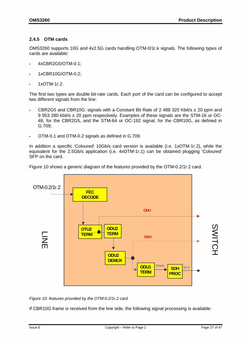
2.4.5 OTM cards
OMS3260 supports 10G and 4x2.5G cards handling OTM-0/1r.k signals. The following types ofcards are available:
• 4xCBR2G5/OTM-0.1;
• 1xCBR10G/OTM-0.2;
• 1xOTM-1r.2.
The first two types are double bit-rate cards. Each port of the card can be configured to accepttwo different signals from the line:
• CBR2G5 and CBR10G: signals with a Constant Bit Rate of 2 488 320 Kbit/s ± 20 ppm and9 953 280 kbit/s ± 20 ppm respectively. Examples of these signals are the STM-16 or OC-48, for the CBR2G5, and the STM-64 or OC-192 signal, for the CBR10G, as defined inG.709;
• OTM-0.1 and OTM-0.2 signals as defined in G.709.
In addition a specific 'Coloured' 10Gb/s card version is available (i.e. 1xOTM-1r.2), while theequivalent for the 2.5Gb/s application (i.e. 4xOTM-1r.1) can be obtained plugging 'Coloured'SFP on the card.
Figure 10 shows a generic diagram of the features provided by the OTM-0.2/1r.2 card.
FECDECODE
OTU2TERM
SDHPROC
ODU1TERM
ODU
ODU
STM16
ODU2DEMUX
ODU2TERM
OTM-0.2/1r.2
VC-4
LINE
SWITC
H
Figure 10: features provided by the OTM-0.2/1r.2 card
If CBR10G frame is received from the line side, the following signal processing is available:

Product Description OMS3260
Page 28 of 47 Copyright – Refer to Page 2 Issue E
• Mapping of CBR10G signal into ODU2 signal. In this case the equipment is used asgateway between the client and the OTN. The ingress card performs the mapping of theCBR10G signal into the ODU2 according to G.709. After the cross-connection the ODU2 isprocessed by the egress card to obtain an OTM-0.2/1r.2 signal. In the Switch to Linedirection the CBR10G signal is extracted from the ODU2 received from the switchingsubsystem;
If OTM0.2/OTM1r.2 frame is received from the line side, the following signal processing isavailable:
• ODU2 cross-connection: In the Line to Switch direction the card first performs errorcorrection decoding the G.709 RS FEC, if enabled, and then terminates the incoming OTU2frame. The ODU2 is then passed to the switching core for cross-connection. In the SwitchSide to Line Side direction the OTU2 frame is generated and, if enabled, FEC is encoded.
• STM-64 termination/generation (option available only for the 'Coloured' version of the card).The ingress card extracts the STM-64 clients from the ODU2 and terminates it down to VC-4 level. In the switch to line direction the VC-4’s received from the switch are assembledinto an STM-64 and then mapped into ODU2 and subsequently into OTU2 together withFEC encoding (if enabled), in order to forward towards the line the outgoing OTN frame.
• ODU1 multiplexing. In the Line to Switch direction the card performs OTU2 termination andde-multiplexing of ODU2 into 4 x ODU1. At this point the card is able to perform on eachODU1 one of the following actions:
- ODU1 cross-connection. The ODU1 is passed to the switching core. In the oppositesense the received ODU1 is multiplexed, with other three ODU1’s, into a single ODU2and then mapped into the outgoing OTU2 frame;
- VC-n cross-connection. The card performs also the extraction of the STM-16 signal fromthe ODU1, and its termination down to VC-4 level. In the Switch to Line direction thecard receives VC-n from the switching core, generates a STM-16 signal, maps it into anODU1 and then performs ODU1 multiplexing.
Similar processing is available on the 4x2.5Gb/s card apart from the ODU multiplexing and theFEC processing. In addition, if the signal received from the line is STM-16, the port can beconfigured to perform the 'classic' SDH processing. On this card each port can be independentlyconfigured (e.g. two ports can be configured as OTM, while the other two as CBR2G5.

OMS3260 Product Description
Issue E Copyright – Refer to Page 2 Page 29 of 47
3 Mapping & multiplexing functionsThe Mapping and Multiplexing functions provide the capability of mapping, aligning andmultiplexing bi-directional logical channels between the SDH physical interfaces. Themultiplexing structure used in the equipment is according to ETSI ETS 300 147 and ITU-TG.707.
OMS3260 is open to support the concatenation of up to two hundred and fifty-six (256)contiguous AU-4s according to G.707, using concatenation indication.
OMS3260 also supports the concatenation of four or sixteen (4/16) contiguous AU-4s, byconverting them into virtual concatenated AU-4s using the STM-16/STM-4 C/V card (both VC-4-4c and VC-4-16c Contiguous to Virtual conversion are supported). The STM-16/STM-4 C/Vcard, that uses hot-pluggable optical transceivers, can be configured as:
• 1xSTM-16 AU4-16c/16v or AU4-4c/4v converter;
• 4xSTM-4 AU4-4c/4v converter.
The use of this unit at the edge of a network, permits to provide a VC-4-4c/16c service even ifthe network doesn't support the routing of VC-4-4c/16c containers.
OMS3260 also allows the mapping of client signal over ODU according to G.709 and ODUmultiplexing according to G.709.
SONET transport over SDH can be supported, ie STS-3c carried as AU-4, STS-12c carried asAU-4-4c, STS-48c carried as AU-4-16c and STS-192c carried as AU-4-64c. The SS bits inthe AU-4 pointer can be configured to support this.
3.1 ConnectivityThe equipment cross connection features are performed by the Switching Matrix and they canbe realised at ODUk (K=1,2) level or at VC-4, VC-4-xc (x = 4, 16, 64) level. Optionally LO-VCswitching capacity can be provided.
The basic functions of the OMS3260 Switching Matrix subsystem are:
• non blocking: the probability that a particular connection request cannot be met is 0;
• full connectivity: it is possible to connect any input to each available output;
• time sequence integrity (concatenated payloads): concatenated payloads are switchedwithout breaking the time sequence integrity;
• assured correctness of cross-connections: correct cross-connections between the righttraffic ports is assured.
The Switching Matrix has a 3-stage Clos structure, and it allows cross-connections for acapacity of 6144 STM-1 equivalent signals.
OMS3260 is designed in order to be upgraded in service to further configurations with highercapacity. The maximum switching capacity (of 6144 STM-1 equivalent) can be achieved in ascalable/non traffic affecting upgrade.

Product Description OMS3260
Page 30 of 47 Copyright – Refer to Page 2 Issue E
Additionally it is possible to migrate from MSH2K/OMS3250 to OMS3260 by an in-serviceupgrade.
MSH64C/OMS3240 and MSH2K/OMS3250 can be used as an SDH/ODU port subrack of theOMS3260.

OMS3260 Product Description
Issue E
4 Network ApplicationsOMS3260 has a particular application in the emerging Optical Transport Network, equivalent tothe one represented by DXC 4/4 in the present SDH network: a point of maximum flexibilityinside the OTN.OMS3260 is the main candidate to be used as link point between the optical backbone and thelower SDH layer.In fact the capability to cross-connect ODUk, with the possibility to cross-connect at VC-4 levelallows an operator to have, in an unique equipment, the functionality performed by an OpticalCross-connect and a DXC 4/4 (please refer to Figure 11 and Figure 12), with the possibility toadd LO-VC switching capability.OMS3260 merges the benefits of an electrical core (e.g. easier performance monitoring andfault location, traffic grooming, wavelength conversion, regeneration of the signals) and the keybenefit, typical of an OXC, of data rate transparency.Additionally the capability to perform the mapping of CBR signals into the OPU/ODU/OTU (thecontainers of OTN defined by G.709) permits the OMS3260 to be used as a gateway betweenthe OTN and SDH layers (please refer to Figure 13).The location of OMS3260 is at the boundary between a SDH network and an OTN.The availability of the tuneable coloured OTN traffic interface provide OMS3260 with a cost-effective and flexible connection toward the photonic layer and eliminates the use of opticaltransponders.
Figure 11: Network layers interconnec
ADM-1
ADM-1
ADM-4
Regional Layer(SDH)
4/1
ONN ONN
ONNOXC
OXC
ONN4/4
4/4
National Layer (OTN)
4/1
ADM 4
Copyright – Refer to Page 2 Page 31 of 47
tions using OXC and DXC 4/4/3

Product Description OMS3260
Page 32 of 47 Copyright – Refer to Page 2 Issue E
Figure 12: Network layers interconnections using OMS3260
Figure 13: OMS3260 flexibility
The main application is the provision of an automatic reconfiguration of channels through thenetwork. Semi-permanent time-limited connections can be realised under a pre-programmedcommand. In general, these functions are provided by an external NMS, or by means of theemerging GMPLS mechanism.
Multiple SDH/OTNRing Closure
DirectSDH/OTN/Ethernet
Services
Direct inter-working into DWDM core viatuneable DWDM Interfaces
OMS3260
960G
VC-4OTM-0.1
ADM-1
ADM-1
ADM-4
ADM 4
Regional Layer(SDH)
ONN ONN
ONNOMS3260
ONN
OMS3260
OXC
OMS3260
National Layer (OTN)

OMS3260 Product Description
Issue E Copyright – Refer to Page 2 Page 33 of 47
5 Equipment Structure5.1 Mechanical StructureOMS3260 has a layout similar to the previous SDH DXC (i.e. MSH8x/9x), including a centralcore for the switching and control subsystems (in 1+1 configuration) and peripheral portsubracks. The switching matrix has a centralised structure (i.e. three stages Clos matrix in thesame subrack).
Despite of the great amount of traffic supported, OMS3260 guarantees a minimum spaceoccupation.
OMS3260 is composed of subracks designed according to the requirements of ETSIspecification ETS 300-119-4.
Each of those subracks is designed to fit within racks designed according to the requirements ofETSI specification ETS 300-119-3.
OMS3260 layout, shown in Figure 14, consists of:
• a single depth (600×300mm, but preferentially 900×300 mm) rack housing the OMS3260core and core protection subracks (please, note that is possible to fit the core subracks intwo different racks and, also, in two different rooms - up to 50m distant).
Please note that the OMS3260 requires no rear access, so the core subrack can bemounted back-to-back or against a wall.
• single depth (600×300mm, but preferentially 900×300 mm) racks, each housing up to amaximum of 40 peripheral high density port subracks (MSH2K/OMS3250 and/orMSH64C/OMS3240 subracks).
Note that the OMS3260 reaches the fully equipped configuration by using only 3MSH2K/OMS3250 port subracks giving a total of 4 racks.
The port subracks can be located up to 100m away from the core subracks and they canalso be mounted back-to-back or against a wall.
Figure 14: Layout example of OMS3260 fully equipped
300 mm900 mm
2200 mm
Traffic
Units
Traffic
Units
Traffic
Units
Coreworking
Coreprotection

Product Description OMS3260
Page 34 of 47 Copyright – Refer to Page 2 Issue E
6 AlarmsAlarms raised by OMS3260 and the related processing are based on ITU-T G.783 and G.784requirements for SDH signals and on ITU-T G.798 for OTM-N.
Alarms from each unit are collected and processed by the Central Control Unit, which performsthe functions listed below:
• alarm inhibition;
• assignment of a category (e.g., urgent, not urgent) to each alarm;
• alarm reduction (removal of consequential alarms);
• alarm prioritisation: a priority value is assigned to each alarm, depending on its type andsource;
• alarm filtering, logging and reporting: capability of selecting, through the above mentionedpriorities, the alarm destination (the NMS and/or the local alarm log and/or the LCT);
• driving of equipment alarm displays and ground contacts.
All the alarm processing functions can be configured via NMS or LCT.
A cyclic local alarm log is available within the equipment.
Alarms can be indicated by lamps/ground contacts, sent to the LCT and to the NMS.
Visual indications are provided to indicate both the alarmed equipment and, in case of internalfault, the affected unit. Either by the LCT or by the NMS, the operator is supported during themaintenance operation, e.g., with fault location and testing functions.

OMS3260 Product Description
Issue E Copyright – Refer to Page 2 Page 35 of 47
7 Equipment ProtectionOMS3260 has been designed in order to guarantee a high level of availability.
All the common parts of the equipment (‘Switching Matrix and Timing Subsystem’, and ‘Controland Communication Subsystems’), are fully duplicated. The functionality of the equipment ismonitored by an alarm system and by built-in test patterns, which allow the cross-connectedpaths between the ports to be monitored in service without affecting traffic.
The protected units within the equipment are:
• Switching Matrix and Timing Subsystem (1+1)
• Control and Communication Subsystem (i.e., Q and QECC management) (1+1)
• Control and Communication connections to peripheral subracks (1+1)
• Power Supply (1+1)
• Control Unit on Port Subracks (1+1)
• Connection Units (on Port Subracks) towards the switch (1+1)

Product Description OMS3260
Page 36 of 47 Copyright – Refer to Page 2 Issue E
8 Network ProtectionNetwork protection is available at each traffic level (i.e. VC-n and STM-N).
In addition to the standard SDH protection (i.e. MSP, 2F/4F MS-SPRING and SNCP), featuresfor the protection of ODU are adopted (i.e. SNC/I and SNC/N).
In order to assure the insertion of OMS3260 into the OTN (Optical Transport Network) a widerange of protection mechanisms are provided.
OMS3260 is able to support network restoration functionality.
Mixed protection can also be applied, for example MS SPRING and SNCP.
8.1 MSP protectionThe MSP function provides protection for the STM-N signal against channel-associated failureswithin a multiplex section. All possible options specified for the "Multiplex Section Protection(MSP) Protocol" (bytes K1 and K2), as defined in ITU-T/G.783 and G.841, can be used.
The following criteria can be used at the receive end for switching to the protection path:
• Signal Fail (LOS, LOF, MS-AIS, Excessive BER) at section level
• Signal Degrade (BER exceeds a preset threshold in the range of 10-5 to 10-9)
• Command from the Local Terminal or from ServiceOn Optical Element Manager andManagement System.
On the STM-1/4/16/64 tributary interfaces, MSP protection is available, using a 1+1 or 1:Narchitecture.
When the MSP 1:N (N≥1) is provided, optional extra traffic is supported.
8.2 MS-SPRing Protection
OMS3260 equipment provides the MS-SPRing ("SDH Multiplex Section Shared ProtectionRing") protection mechanism. Its general features are defined in ITU-T Rec. 803, while thecomplete description of the protocol can be found in ITU-T Rec. G.841. Both two and four fibreoptions are supported.
The MS-SPRing protocol manages the NUT (Non Pre-emptable Unprotected Traffic) as definedin the latest G.841 version.
The equipment can be configured for particular network applications to support multiple ringseach protected by MS-SPRing.
MS-SPRing is characterised by dividing the total payload (in every STM-N link) equally intoworking and protection capacity. The working traffic is bi-directional over a single path (e.g. A-Band B-A in Figure 15). The protection capacity is shared by all the working sections and notdedicated to each connection on the ring.

OMS3260 Product Description
Issue E Copyright – Refer to Page 2 Page 37 of 47
A B
CDC-A A-C
A-B B-AA-BB-A
A-CC-A
a: 2-fibre SPRing (Normal Condition)
Figure 15: Two fibre MS-SPRing (Normal Condition)
In case of link or node failure a loopback is performed at the nodes adjacent to the failed link ornode (see Figure 16 and Figure 17).
A B
CDC-A A-C
A-B B-AA-BB-A
A-CC-A
b: 2-fibre SPRing (UnidirectionalLink Failure)
Figure 16: Two fibre MS-SPRing (Unidirectional Link Failure)
A B
CDC-A A-C
A-B B-AA-BB-A
A-CC-A
WorkingProtection
c: 2-fibre SPRing (Node Failure)
Figure 17: Two fibre MS-SPRing (Node Failure)
The relevant Switch Matrix Unit implements the loopback. The protection mechanism can beactivated by the following criteria:
Product Description OMS3260
Page 38 of 47 Copyright – Refer to Page 2 Issue E
• Signal Fail at section level (LOS, LOF, MS-AIS, excessive BER);
• Signal Degrade (BER exceeds a preset threshold in the range of 10-5 to 10-9);
• Command from the Local Terminal or Element Manager.
All these procedures are managed by an appropriate APS (Automatic Protection Switching)protocol provided by K1, K2 bytes. As an option low priority traffic can be managed.
8.3 Ring Interworking ProtectionInter-working SDH protection architectures is meant to provide an even greater degree ofprotection within a network. Ring inter-working is accommodated in such a way that if two ringsare connected at more than one node each, a failure at one of these nodes shall not cause lossof any service.OMS3260 supports interworking between SNCP protected rings, MS-SPRing protected ringsand mixtures of the two, according to ITU-T G.842. Overlapping SNCP should be used as analternative and simpler method.
8.4 OTN ProtectionOMS3260 supports the following types of protection architectures for an OTN network:
• Inherent Subnetwork Connection Protection (SNC/I) on ODUk (that is equivalent, forswitching criteria point of view, to an OTUk Trail protection);
• Non-intrusive Subnetwork Connection Protection (SNC/N) on ODUk;
Each protection application makes use of pre-assigned capacity between nodes.
The following ODUk protection architectures can be supported:
• 1+1 unidirectional SNC/N and SNC/I
In these architectures, a permanent bridge is utilised at the transmit end. At the receiverend, a protection switch is realized by selecting one of the signals based on purely localinformation.
For protection switching criteria, non-intrusive (SNC/N) or server layer (SNC/I) monitoringshall be used.
• 1+1 bi-directional SNC/N and SNC/I
In these architectures, a permanent bridge is utilised at the transmit end. At the receiveend, a protection switch is realised by selecting one of the signals based on local or remoteinformation. For protection switching criteria, non-intrusive (SNC/N) or server layer (SNC/I)monitoring is used.
These types of protection use the automatic protection switching protocol (APS).
• 1:N an SNC/I protection
In this architecture N working subnetwork connections that are to be protected share anadditional subnetwork connection for protection purposes. In a normal condition, thisprotection capacity can be used to carry lower priority “extra traffic”. This extra traffic itself isnot protected and is to be replaced by higher priority working traffic under failure conditions.This architecture requires the APS as protection control.

OMS3260 Product Description
Issue E Copyright – Refer to Page 2 Page 39 of 47
For protection switching criteria, server layer (SNC/I) monitoring is used.
The architecture can be unidirectional or bi-directional.
For 1+1 architecture the revertive or non-revertive mode of operations is available.
For each type of protection, a manual external command is available to the operator.
8.5 OS Restoration
It is possible to perform network protection using rerouting. This protection scheme is mainlyoperated by the network management system using the capabilities of cross-connectionreconfiguration offered by OMS3260.
Spare capacity is reserved on each link of a meshed network in order to provide alternativeroutes on which traffic can be transported. In case of cable break the traffic transported by thefailed link is redirected along pre-programmed or on-line calculated alternative routes using theavailable reserved capacity.
8.6 Fast Restoration
As well as conventional SDH protection schemes the OMS3260 supports ITU-T (ASON/ASTN)based fast network restoration. This method of protection is particularly effective in meshnetwork architectures.
The OMS3260 simultaneously supports all SDH protection schemes and network restorationmaking it the ideal switching solution for operators wishing to migrate from one scheme toanother. The Marconi solution offers full scalability to meet the needs of large operators whotypically could have hundreds of dynamic elements in their networks.
Spare capacity is reserved on each link of a meshed network, in order to provide alternativeroutes on which traffic can be transported. In case of a cable break the traffic transported by thefailed link is redirected along pre-programmed or on-line calculated alternative routes using theavailable reserved capacity.
This protection scheme can be applied at any cross-connected level, i.e. VC4, VC4-nc andODU.
Product Description OMS3260
Page 40 of 47 Copyright – Refer to Page 2 Issue E
9 AUTOMATIC SWITCHING TRANSPORT NETWORK with OMS3260The OMS3260 may be introduced into an existing network to provide a new layer of transportnetwork where the concept of ASTN can be applied to achieve faster trail routing, connectionset-up and tear down and fast network restoration.
All those operations are currently carried out by the traditional Network Management Systemwith typical execution time in the order of minutes, while a distributed intelligence would allowthe same operations to be carried out in hundreds of milliseconds.
The ASTN control plane will allow faster connection set-up thanks to improved automaticrouting algorithms and signaling. Such mechanisms allow faster implementation of on-the-flyrestoration mechanisms.
The distributed intelligence enables the first NE to recalculate the path and signal therestoration route throughout the network, thus implementing fast restoration mechanisms withthe sharing of restoration resources.
UNI interfaces will also be available to support OVPN services and direct connection set-up andtear down from client interfaces.
The ASTN functionality has been realised in three phases:
1. Fully centralised implementation - The function is implemented in a fully centralised solution.UNI interface is implemented in the centralised application. All the network topology informationis automatically handled by the function. This implementation can be applied to all networkproducts (including legacy) without a network element field upgrade. Such a centralised solutionis provided with NNI and NMI interface to allow interworking with the other control planes.
2. Centralised routing function, distributed routing protocol - A signalling protocol is implementedin the embedded software of the network elements, this will speed up the path implementationprocess. The signalling protocol is compatible with the traditional OSI based DCN. For someprotection schemes, the network elements will also have the capability to store the alternateroute without implementing it prior to failure occurrence. The path computation function willremain centralised.
3. Fully distributed implementation - Fully standard UNI interfaces are integrated in the networkelements, thus avoiding the need for adapter devices. A fully distributed control plane isavailable directly in the network elements. This features a Link Management Protocol (LMP) forautomatic neighbour discovery, an IP-based Link State Routing Protocol (OSPF-TE) forautomatic topology and resource discovery and a signalling protocol with explicit routingcapability (RSVP-TE). Centralised functions (e.g., client database) will continue to be supported.

OMS3260 Product Description
Issue E Copyright – Refer to Page 2 Page 41 of 47
10 Performance Monitoring and ManagementPerformance Management refers to the capability of controlling the Performance Monitoringprocess by means of the generation of performance data, the reporting of performance data,and the reporting of threshold crossing.
The monitoring of performance parameters is based on the evaluation of errored blocks (EB).OMS3260 is able to perform Performance Monitoring at SDH and OTN level.
Performance Monitoring and Management are in accordance with ITU-T Recs. G.784, G.826,G.828, G.829, G7710, G874, G798.
The parameters that are related to the performance monitoring are provided in the following:
• BBE (Background Block Error);
• ES (Errored Second);
• SES (Severely Errored Second);
• OFS (Out of Frame Second, only SDH);
• SEP (Severely Errored Period, only OTN)
• FCE (FEC Corrected Errors, only OTN)
The following additional parameters can be optionally monitored:
• CSES (Consecutive SES);
• UAS (Unavailable Seconds);
• AU PJE (Negative/Positive Administrative Unit Pointer Justification Events, only SDH).
All these parameters are evaluated and stored in 15 min and 24 hr registers according to G.784requirements.
Such performance data is available to the System Manager (operator) (see EquipmentManagement).

Product Description OMS3260
Page 42 of 47 Copyright – Refer to Page 2 Issue E
11 Equipment ManagementOMS3260 can be monitored and controlled via:
• F interface to a LCT (Personal Computer equipped with appropriate operating system andapplication software);
• Q interface, to the NMS; on the basis of ITU-T Recs. Q.811 and Q.812 (formerly in ITU-TG.773).
• QECC (from an STM-N interface), as defined by ITU-T Rec. G.784;
• GMPLS (General Multi-Protocol Label Switching) mechanism.
The equipment also supports TCP/IP interface.The provided OAM&P (Operations, administration, maintenance and provisioning) functions arein accordance with ITU-T/G.784. In particular it is possible to perform:
• configuration management:
• provisioning (configuration of all equipment characteristics, e.g. internal channel routing);
• protection switching management;
• installation;
• fault (maintenance) management:
• alarm surveillance (collection, filtering, reporting);
• testing (equipment and connections);
• performance management:
• performance data collection;
• performance data reporting;
• general functions (e.g. security, software download).
The equipment supports the ITU-T/ETSI standard information model.
More precisely, OMS3260 is designed to support the information model based on:
• ITU-T Recommendations M.3100, G.774;
• ETSI ETS 300 304, ETS 300 371.

OMS3260 Product Description
Issue E Copyright – Refer to Page 2 Page 43 of 47
12 ServicesCommunication channels for service functions can be provided using STM-N overhead bytes.All SOH and POH associated accessible bytes are made available, according toRecommendation ITU-T G.707, at the optional Auxiliary subsystem connectors in order to allowcustomisation of service transport. The optional Auxiliary Unit performs these functions on theequipment.
The following type of services and interfaces are available:
• EOW using E1/E2 bytes with 2 wire analogue interface;
• Data channels transported by standard interfaces.

Product Description OMS3260
Page 44 of 47 Copyright – Refer to Page 2 Issue E
13 General operating featuresThe equipment assists the operators in many common tasks, defined as general operatingfeatures, related with:
• equipment use;
• plug-in unit handling;
• fault maintenance (self diagnostic);
• recovery from faults;
• equipment robustness;
• inventory.
13.1 Equipment UseThe equipment is designed to support the operator during installation and to provide usefulfacilities like manual restart, software and hardware consistency check, and the possibility ofupgrading the system functionality without disturbing traffic.
13.2 Plug-in Unit HandlingReplacement of one plug-in unit with one of the same type does not require any reconfigurationon all the other units on the shelf. The newly inserted unit is automatically configured the sameas the extracted one.
Removal and insertion of the units are reported to the management system.
13.3 Fault Management (Self Diagnostic)Built-in diagnostic facilities identify the unit that requires to be changed or the faulty interface, forall faults occurring within the equipment are detectable at its interfaces.
This operation is carried out automatically using non-intrusive monitoring inside the networkelement.Management and operation of the diagnostic facilities are available both from a remote locationand from local operation. The equipment is capable of:• automatically transferring an alarm report with data about the failure to a remote
management centre immediately on detection of a failure;
• automatically switching on detecting a fault to the protection units, if duplicated units areinstalled.
13.4 Recovery From FaultsA failure in the control unit does not cause traffic outage or affect the operation of networkprotection. The control unit contains and updates a complete and accurate ManagementInformation Base that corresponds to the hardware state of the equipment.
13.5 Equipment RobustnessThe equipment is designed to protect the system data against unintentional modifications.

OMS3260 Product Description
Issue E Copyright – Refer to Page 2 Page 45 of 47
13.6 InventoryThe equipment maintains a record of all its component units. Each equipment is modelled as acollection of managed objects as detailed in ITU-T Rec. G.774 SDH Information Model.
The equipment performs the following features:
• the Electronic Inventory Data is automatically updated at all times and is the current recordof all the parts forming the equipment;
• all inventory information held by the equipment is accessible by the LCT and NMS;
• physical details (e.g. code, serial number, version) of all the hardware and software partswhich form the equipment are stored.
• the storage of inventory data within the equipment is non-volatile;
• all inventory information relating to a network element can be accessed remotely

Product Description OMS3260
Page 46 of 47 Copyright – Refer to Page 2 Issue E
14 Technical Specifications
14.1 Electrical EnvironmentThe equipment is in compliance with: EEC Council Directive 89/336/EEC;
ETS 300 386-2 (EMC/EMI/ESD).
The requirements are met by the subrack alone and do not rely on any features of the rack.
14.2 Climatic and Mechanical Environment14.2.1 GeneralThe minimal classes of environmental conditions, their severity and general definitions arespecified according to ETSI ETS 300-019-1-0.
14.2.2 Storage EnduranceStorage endurance minimal requirements are according to ETSI ETS 300 019-1-1, Class 1.2,"Non temperature controlled storage locations".
14.2.3 Transport EnduranceTransport endurance minimal requirements are according to ETSI ETS 300 019-1-2, Class 2.3,"Public Transportation".
14.2.4 Environmental Endurance For Indoor OperationWeather-protected stationary use endurance minimal requirements are according to ETSI ETS300 019-1-3, Class 3.2, "Partly temperature controlled locations".
14.3 System Performance14.3.1 Error PerformanceThe general error performance is that no errors are introduced into traffic by the equipmentunder the most adverse environmental and operational conditions specified.
14.3.2 Transmission DelayThe delay times for a transmission signal from its input to its output for multiplexing functions is≤ 125 µs.
14.4 Power Requirements (according to ETSI ETS 300-132)The equipment operates without pre-setting in the range -38.4 to -72 V, suitable for the batteryvoltages (supplied by two separate fuse protected and diode connected parallel lines).
Supply voltages: -48V +/- 20%
-60V +/- 20%
OMS3260 Product Description
Issue E Copyright – Refer to Page 2 Page 47 of 47
The power supply from the mains (duplicated) is also possible by using external AC/DCconverters suitable for rack mounting and located on a different shelf.
Earthing is in accordance with ETSI standard ETS 300 253.
14.5 SynchronisationSynchronisation sources available:
• Independent external reference input:
2 MHz G.703-13
2 Mb/s framed G.703-9, G.706
2 Mb/s unframed G.703-9;
• Recovered tributary timing derived STM-N tributary interface
• Internal oscillator on the Switch Unit (stab. better than 4.6 ppm. acc. to G.813)
• Independent synchronisation outputs are available:
2 MHz G.703-13
2 Mb/s framed G.703-9, G.706 with SSM
2 Mb/s framed G.703-9, G.706 w/o SSM
14.6 Safety14.6.1 GeneralThe equipment is designed not to cause any harm or danger to personnel installing, maintainingor operating the equipment, and not to produce any damage to the network or other equipmentconnected to it.
14.6.2 Optical safety requirementsThe automatic laser shutdown function complies with ITU-T G.958/G.664.
End of Document