Embed Size (px)
Citation preview
MSP-EXP430G2 LaunchPad ExperimenterBoard
User's Guide
Literature Number: SLAU318B
July 2010–Revised March 2012
Contents
Preface ....................................................................................................................................... 41 MSP-EXP430G2 LaunchPad Overview ................................................................................... 5
1.1 Overview .................................................................................................................. 5
1.2 Kit Contents .............................................................................................................. 6
1.3 Revisions ................................................................................................................. 6
2 Installation ......................................................................................................................... 72.1 Download the Required Software ..................................................................................... 7
2.2 Install the Software ...................................................................................................... 7
2.3 Install the Hardware ..................................................................................................... 7
3 Getting Started With MSP-EXP430G2 LaunchPad .................................................................... 73.1 Getting Started ........................................................................................................... 7
3.2 Demo Application, Internal Temperature Measurement ............................................................ 7
4 Develop an Application With the MSP-EXP430G2 LaunchPad ................................................... 84.1 Developing an Application .............................................................................................. 8
4.2 Program and Debug the Temperature Measurement Demo Application ........................................ 8
4.3 Disconnect Emulator From Target With Jumper J3 ................................................................. 9
4.4 Program Connected eZ430 Target Boards ......................................................................... 10
4.5 Connecting a Crystal Oscillator ...................................................................................... 11
4.6 Connecting a Satellite Board ......................................................................................... 11
4.7 Supported Devices ..................................................................................................... 11
5 MSP-EXP430G2 Hardware .................................................................................................. 135.1 Device Pinout ........................................................................................................... 13
5.2 Schematics Emulator .................................................................................................. 14
5.3 PCB Layout ............................................................................................................. 17
5.4 Bill of Materials (BOM) ................................................................................................ 20
6 Suggested Reading ........................................................................................................... 217 Frequently Asked Questions (FAQ) ...................................................................................... 21
2 Table of Contents SLAU318B–July 2010–Revised March 2012Submit Documentation Feedback
Copyright © 2010–2012, Texas Instruments Incorporated
www.ti.com
List of Figures
1 MSP-EXP430G2 LaunchPad Overview.................................................................................. 6
2 Insert Device Into Target Socket.......................................................................................... 8
3 Code Composer Studio™ v4 in Debugging Mode...................................................................... 9
4 MSP-EXP430G2 LaunchPad With Attached eZ430-RF2500 Target Board ....................................... 10
5 Device Pinout .............................................................................................................. 13
6 Schematics, Emulator (1 of 3) ........................................................................................... 14
7 Schematics, Emulator (2 of 3) ........................................................................................... 15
8 Schematics, Target Socket (3 of 3) ..................................................................................... 16
9 Layout, LaunchPad Top Layer........................................................................................... 17
10 Layout, LaunchPad Bottom Layer....................................................................................... 18
11 Layout, LaunchPad Silkscreen .......................................................................................... 19
List of Tables
1 Jumper Connection J3 Between Emulator and Target................................................................. 9
2 eZ430 Debugging Interface .............................................................................................. 10
3 Supported Devices ........................................................................................................ 11
4 Bill of Materials............................................................................................................. 20
3SLAU318B–July 2010–Revised March 2012 List of FiguresSubmit Documentation Feedback
Copyright © 2010–2012, Texas Instruments Incorporated
PrefaceSLAU318B–July 2010–Revised March 2012
Read This First
If You Need Assistance
If you have any feedback or questions, support for the MSP430™ devices and the MSP-EXP430G2 isprovided by the Texas Instruments Product Information Center (PIC) and the TI E2E Forum(https://community.ti.com/forums/12.aspx). Contact information for the PIC can be found on the TI web siteat http://support.ti.com. Additional device-specific information can be found on the MSP430 web site athttp://www.ti.com/msp430.
Related Documentation from Texas Instruments
The primary sources of MSP430 information are the device-specific data sheets and user's guidesavailable at the Texas Instruments MSP430 web site: http://www.ti.com/msp430.
MSP430 device user's guides, application reports, software examples and other MSP430 user's guidescan be found at the Tech Docs section. The CCS user's guide includes detailed information on setting upa project and using Code Composer Studio for the MSP430 microcontroller (SLAU157).
Information specific to the MSP-EXP430G2 LaunchPad Experimenter Board, all the available IDEs,Software Libraries, and examples can be found at the Tools & Software section:http://www.ti.com/tool/msp-exp430g2.
FCC Warning
This equipment is intended for use in a laboratory test environment only. It generates, uses, and canradiate radio frequency energy and has not been tested for compliance with the limits of computingdevices pursuant to subpart J of part 15 of FCC rules, which are designed to provide reasonableprotection against radio frequency interference. Operation of this equipment in other environments maycause interference with radio communications, in which case, the user will be required to take whatevermeasures may be required to correct this interference his own expense.
MSP430, Code Composer Studio are trademarks of Texas Instruments.IAR Embedded Workbench is a trademark of IAR Systems.All other trademarks are the property of their respective owners.
4 Preface SLAU318B–July 2010–Revised March 2012Submit Documentation Feedback
Copyright © 2010–2012, Texas Instruments Incorporated
User's GuideSLAU318B–July 2010–Revised March 2012
MSP-EXP430G2 LaunchPad Experimenter Board
1 MSP-EXP430G2 LaunchPad Overview
1.1 Overview
The MSP-EXP430G2 low-cost experimenter board called LaunchPad is a complete development solutionfor the Texas Instruments MSP430G2xx Value Line series. The integrated USB-based emulator offers allthe hardware and software necessary to develop applications for all MSP430G2xx series devices. TheLaunchPad has an integrated DIP target socket that supports up to 20 pins, allowing MSP430™ ValueLine devices to be dropped into the LaunchPad board. It also offers an on-board flash emulation toolallowing direct interface to a PC for easy programming, debugging, and evaluation. The LaunchPadexperimenter board is capable of programming the eZ430-RF2500T target boards, the eZ430-Chronoswatch module or the eZ430-F2012T/F2013T target boards. The USB interface provides a 9600-BaudUART serial connection from the MSP430G2xx device to the host PC or a connected target board.
The MSP-EXP430G2 can be used with IAR Embedded Workbench™ Integrated DevelopmentEnvironment (IDE) or Code Composer Studio™ (CCS) IDE to write, download, and debug applications.The debugger is unobtrusive, allowing the user to run an application at full speed with hardwarebreakpoints and single stepping available while consuming no extra hardware resources.
MSP-EXP430G2 LaunchPad features:
• USB debugging and programming interface featuring a driverless installation and application UARTserial communication with up to 9600 Baud
• Supports all MSP430G2xx and MSP430F20xx devices in PDIP14 or PDIP20 packages
• Two general-purpose digital I/O pins connected to green and red LEDs for visual feedback
• Two push button for user feedback and device reset
• Easily accessible device pins for debugging purposes or as socket for adding customized extensionboards
• High-quality 20-pin DIP socket for an easy plug-in or removal of the target device
5SLAU318B–July 2010–Revised March 2012 MSP-EXP430G2 LaunchPad Experimenter BoardSubmit Documentation Feedback
Copyright © 2010–2012, Texas Instruments Incorporated
MSP-EXP430G2 LaunchPad Overview www.ti.com
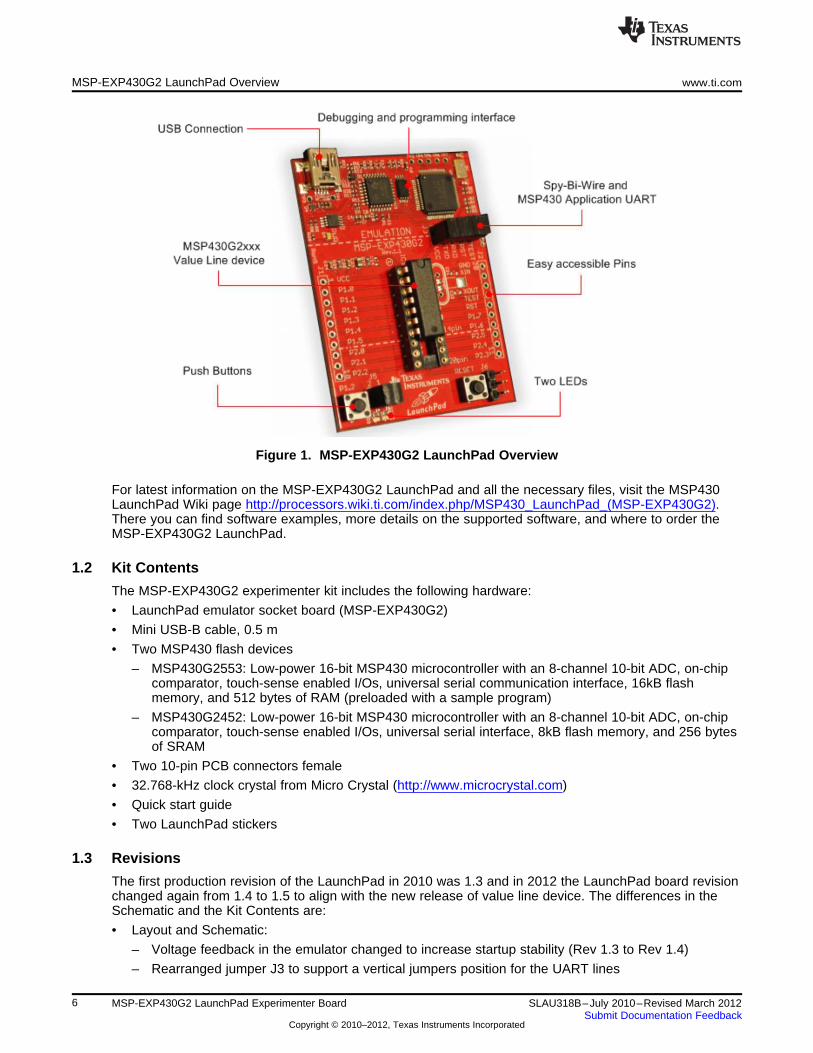
Figure 1. MSP-EXP430G2 LaunchPad Overview
For latest information on the MSP-EXP430G2 LaunchPad and all the necessary files, visit the MSP430LaunchPad Wiki page http://processors.wiki.ti.com/index.php/MSP430_LaunchPad_(MSP-EXP430G2).There you can find software examples, more details on the supported software, and where to order theMSP-EXP430G2 LaunchPad.
1.2 Kit Contents
The MSP-EXP430G2 experimenter kit includes the following hardware:
• LaunchPad emulator socket board (MSP-EXP430G2)
• Mini USB-B cable, 0.5 m
• Two MSP430 flash devices
– MSP430G2553: Low-power 16-bit MSP430 microcontroller with an 8-channel 10-bit ADC, on-chipcomparator, touch-sense enabled I/Os, universal serial communication interface, 16kB flashmemory, and 512 bytes of RAM (preloaded with a sample program)
– MSP430G2452: Low-power 16-bit MSP430 microcontroller with an 8-channel 10-bit ADC, on-chipcomparator, touch-sense enabled I/Os, universal serial interface, 8kB flash memory, and 256 bytesof SRAM
• Two 10-pin PCB connectors female
• 32.768-kHz clock crystal from Micro Crystal (http://www.microcrystal.com)
• Quick start guide
• Two LaunchPad stickers
1.3 Revisions
The first production revision of the LaunchPad in 2010 was 1.3 and in 2012 the LaunchPad board revisionchanged again from 1.4 to 1.5 to align with the new release of value line device. The differences in theSchematic and the Kit Contents are:
• Layout and Schematic:
– Voltage feedback in the emulator changed to increase startup stability (Rev 1.3 to Rev 1.4)
– Rearranged jumper J3 to support a vertical jumpers position for the UART lines
6 MSP-EXP430G2 LaunchPad Experimenter Board SLAU318B–July 2010–Revised March 2012Submit Documentation Feedback
Copyright © 2010–2012, Texas Instruments Incorporated
www.ti.com Installation
– VCC on the connector J4 can now be disconnected from the emulator VCC by J3
– Pullup resistor R34 and capacitor C24 on P1.3 removed to reduce the current consumption
– Presoldered male headers J1 and J2
2 Installation
The MSP-EXP430G2 LaunchPad installation consists of three easy steps:
1. Download the required software.
2. Install the selected IDE.
3. Connect the LaunchPad to the PC.
Then the LaunchPad is ready to develop applications or to use the pre-programmed demo application.
2.1 Download the Required Software
Different development software tools are available for the MSP-EXP430G2 LaunchPad developmentboard. IAR Embedded Workbench™ KickStart IDE and Code Composer Studio™ (CCS) IDE are bothavailable in a free limited version. IAR Embedded Workbench allows 4kB of C-code compilation. CCS islimited to a code size of 16kB. The software is available at http://www.ti.com/msp430 or the LaunchPadWiki page http://processors.wiki.ti.com/index.php/MSP430_LaunchPad_(MSP-EXP430G2). There aremany other compilers and integrated development environments (IDEs) available to use with the MSP-EXP430 LaunchPad including Rowley Crossworks and MSPGCC. However, example projects have beencreated using IAR Embedded Workbench KickStart and Code Composer Studio (CCS). For moreinformation on the supported software and the latest code examples, visit the LaunchPad Wiki page.
2.2 Install the Software
Download one of the integrated development environments (IDEs). IAR KickStart and CCS offer therequired driver support to work with the MSP-EXP430 LaunchPad onboard emulation. Once installed, theIDE should find the MSP-EXP430G2 LaunchPad as USB:HID debugging interface. Now all is set fordeveloping MSP430G2xx based application on the LaunchPad.
2.3 Install the Hardware
Connect the MSP-EXP430G2 LaunchPad socket board with the enclosed USB cable to a PC. The driverinstallation starts automatically. If prompted for software, allow Windows to install the softwareautomatically. This is possible only if either IAR KickStart or Code Composer Studio is already installed(see Section 2.2).
3 Getting Started With MSP-EXP430G2 LaunchPad
3.1 Getting Started
The first time the MSP-EXP430G2 LaunchPad Experimenter Board is used, a demo applicationautomatically starts as soon as the board is powered from the USB host. To start the demo, connect theMSP-EXP430G2 LaunchPad with the included mini USB cable to a free USB port. The demo applicationstarts with an LED toggle to show the device is active. More information about the demo application canbe found in Section 3.2.
3.2 Demo Application, Internal Temperature Measurement
The LaunchPad includes a pre-programmed MSP430G2553 device already installed in the target socket.When LaunchPad is connected via USB, the demo starts with an LED toggle sequence. The onboardemulation generates the supply voltage and all the signals necessary to start.
7SLAU318B–July 2010–Revised March 2012 MSP-EXP430G2 LaunchPad Experimenter BoardSubmit Documentation Feedback
Copyright © 2010–2012, Texas Instruments Incorporated
Develop an Application With the MSP-EXP430G2 LaunchPad www.ti.com
Press button P1.3 to switch the application to a temperature measurement mode. A reference temperatureis taken at the beginning of this mode, and the LEDs of the LaunchPad signal a rise or fall in temperatureby varying the brightness of the on-board red or green LED, respectively. The reference temperature canalso be recalibrated with another button press on P1.3. The collected temperature data is alsocommunicated via back-channel UART through the USB emulation circuitry back to the PC. Thetransmitted values representing the temperature measured with the MSP430G2553 internal temperaturesensor in Fahrenheit and can be displayed with any terminal application or the Temperature Sensor GUIavailable on the MSP430 LaunchPad wiki pagehttp://processors.wiki.ti.com/index.php/MSP430_LaunchPad_(MSP-EXP430G2). The serial communicationport on the PC must be configured with 2400 bps, one stop bit, and no flow control to display the valuescorrectly.
The demo application uses the on-chip peripherals of the MSP430G2553 device such as the 10-bit ADC,which samples the internal temperature sensor, and 16-bit timers, which drive the PWM to vary brightnessof the LEDs and enable software UART for communication with the PC. The MSP430G2553 offers a USCIinterface that is capable of communicating through UART at up to 2 MBaud, but to be aligned with all theother MSP430G2xx devices, the demo uses the Timer UART implementation, which can be used on allthe other devices. This way the demo can be used with any other MSP430G2xx device with an integratedADC, without any change in the program. The source code for this pre-loaded demo application isavailable for download in the Projects section of the MSP430 LaunchPad wiki page. Further informationon the Temperature Sensor application and other examples and applications can be found on theMSP430 LaunchPad wiki page as well.
The provided applications can be a great starting point for various custom applications and give a goodoverview of the manifold possibilities of the MSP430G2xx Value Line devices. Also available are theexecutable and source files for a GUI, which displays the data that is being communicated back to the PCfrom the LaunchPad.
4 Develop an Application With the MSP-EXP430G2 LaunchPad
4.1 Developing an Application
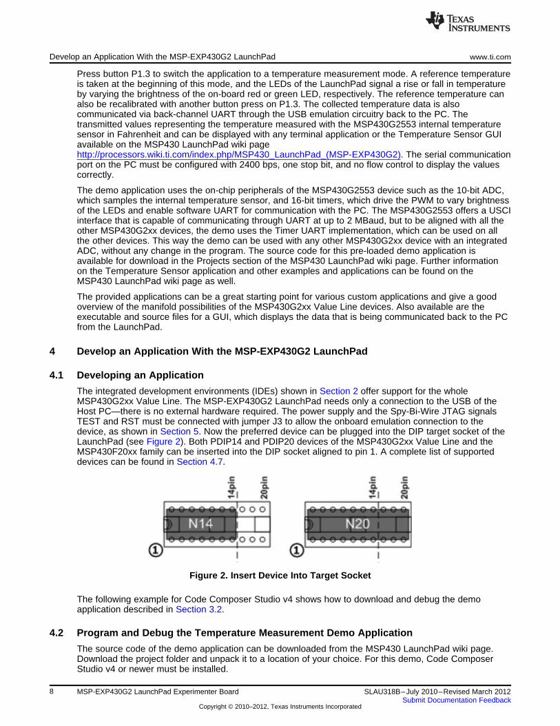
The integrated development environments (IDEs) shown in Section 2 offer support for the wholeMSP430G2xx Value Line. The MSP-EXP430G2 LaunchPad needs only a connection to the USB of theHost PC—there is no external hardware required. The power supply and the Spy-Bi-Wire JTAG signalsTEST and RST must be connected with jumper J3 to allow the onboard emulation connection to thedevice, as shown in Section 5. Now the preferred device can be plugged into the DIP target socket of theLaunchPad (see Figure 2). Both PDIP14 and PDIP20 devices of the MSP430G2xx Value Line and theMSP430F20xx family can be inserted into the DIP socket aligned to pin 1. A complete list of supporteddevices can be found in Section 4.7.
Figure 2. Insert Device Into Target Socket
The following example for Code Composer Studio v4 shows how to download and debug the demoapplication described in Section 3.2.
4.2 Program and Debug the Temperature Measurement Demo Application
The source code of the demo application can be downloaded from the MSP430 LaunchPad wiki page.Download the project folder and unpack it to a location of your choice. For this demo, Code ComposerStudio v4 or newer must be installed.
8 MSP-EXP430G2 LaunchPad Experimenter Board SLAU318B–July 2010–Revised March 2012Submit Documentation Feedback
Copyright © 2010–2012, Texas Instruments Incorporated
www.ti.com Develop an Application With the MSP-EXP430G2 LaunchPad
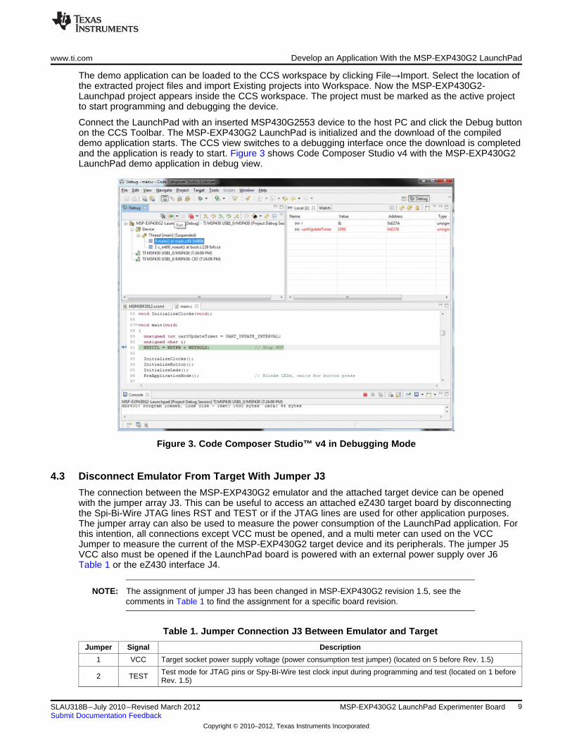
The demo application can be loaded to the CCS workspace by clicking File→Import. Select the location ofthe extracted project files and import Existing projects into Workspace. Now the MSP-EXP430G2-Launchpad project appears inside the CCS workspace. The project must be marked as the active projectto start programming and debugging the device.
Connect the LaunchPad with an inserted MSP430G2553 device to the host PC and click the Debug buttonon the CCS Toolbar. The MSP-EXP430G2 LaunchPad is initialized and the download of the compileddemo application starts. The CCS view switches to a debugging interface once the download is completedand the application is ready to start. Figure 3 shows Code Composer Studio v4 with the MSP-EXP430G2LaunchPad demo application in debug view.
Figure 3. Code Composer Studio™ v4 in Debugging Mode
4.3 Disconnect Emulator From Target With Jumper J3
The connection between the MSP-EXP430G2 emulator and the attached target device can be openedwith the jumper array J3. This can be useful to access an attached eZ430 target board by disconnectingthe Spi-Bi-Wire JTAG lines RST and TEST or if the JTAG lines are used for other application purposes.The jumper array can also be used to measure the power consumption of the LaunchPad application. Forthis intention, all connections except VCC must be opened, and a multi meter can used on the VCCJumper to measure the current of the MSP-EXP430G2 target device and its peripherals. The jumper J5VCC also must be opened if the LaunchPad board is powered with an external power supply over J6Table 1 or the eZ430 interface J4.
NOTE: The assignment of jumper J3 has been changed in MSP-EXP430G2 revision 1.5, see thecomments in Table 1 to find the assignment for a specific board revision.
Table 1. Jumper Connection J3 Between Emulator and Target
Jumper Signal Description
1 VCC Target socket power supply voltage (power consumption test jumper) (located on 5 before Rev. 1.5)
Test mode for JTAG pins or Spy-Bi-Wire test clock input during programming and test (located on 1 before2 TEST Rev. 1.5)
9SLAU318B–July 2010–Revised March 2012 MSP-EXP430G2 LaunchPad Experimenter BoardSubmit Documentation Feedback
Copyright © 2010–2012, Texas Instruments Incorporated
Develop an Application With the MSP-EXP430G2 LaunchPad www.ti.com
Table 1. Jumper Connection J3 Between Emulator and Target (continued)
Jumper Signal Description
3 RST Reset or Spy-Bi-Wire test data input/output during programming and test (located on 2 before Rev. 1.5)
4 RXD UART receive data input (direction can be selected by jumper orientation) (located on 3 before Rev. 1.5)
5 TXD UART transmit data output (direction can be selected by jumper orientation) (located on 4 before Rev. 1.5)
Jumpers 4 and 5 connect the UART interface of the emulator to the target device pins P1.1 and P1.2. Thedirection of the UART signal lines can be selected by the orientation of the attached jumpers. In horizontalorientation, the jumpers connect TXD to P1.1 and RXD to P1.2, as they are used for the software UARTcommunication on the demo application (see Section 3.2). In vertical orientation, the jumpers connect theTXD signal to P1.2 and the RXD signal to P1.1, as required for the MSP430G2553 USCI.
4.4 Program Connected eZ430 Target Boards
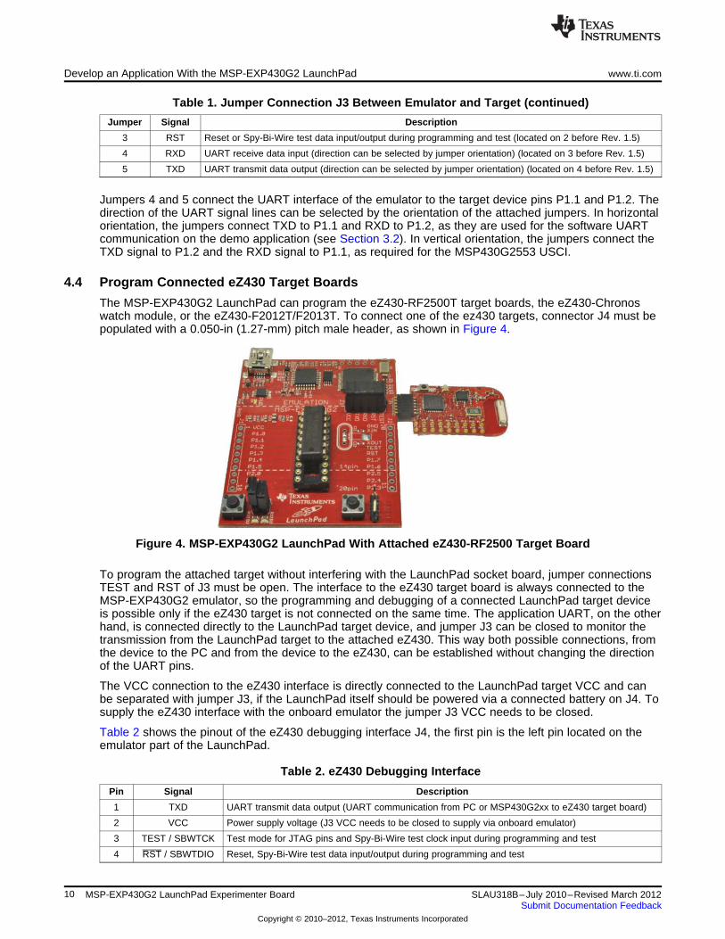
The MSP-EXP430G2 LaunchPad can program the eZ430-RF2500T target boards, the eZ430-Chronoswatch module, or the eZ430-F2012T/F2013T. To connect one of the ez430 targets, connector J4 must bepopulated with a 0.050-in (1.27-mm) pitch male header, as shown in Figure 4.
Figure 4. MSP-EXP430G2 LaunchPad With Attached eZ430-RF2500 Target Board
To program the attached target without interfering with the LaunchPad socket board, jumper connectionsTEST and RST of J3 must be open. The interface to the eZ430 target board is always connected to theMSP-EXP430G2 emulator, so the programming and debugging of a connected LaunchPad target deviceis possible only if the eZ430 target is not connected on the same time. The application UART, on the otherhand, is connected directly to the LaunchPad target device, and jumper J3 can be closed to monitor thetransmission from the LaunchPad target to the attached eZ430. This way both possible connections, fromthe device to the PC and from the device to the eZ430, can be established without changing the directionof the UART pins.
The VCC connection to the eZ430 interface is directly connected to the LaunchPad target VCC and canbe separated with jumper J3, if the LaunchPad itself should be powered via a connected battery on J4. Tosupply the eZ430 interface with the onboard emulator the jumper J3 VCC needs to be closed.
Table 2 shows the pinout of the eZ430 debugging interface J4, the first pin is the left pin located on theemulator part of the LaunchPad.
Table 2. eZ430 Debugging Interface
Pin Signal Description
1 TXD UART transmit data output (UART communication from PC or MSP430G2xx to eZ430 target board)
2 VCC Power supply voltage (J3 VCC needs to be closed to supply via onboard emulator)
3 TEST / SBWTCK Test mode for JTAG pins and Spy-Bi-Wire test clock input during programming and test
4 RST / SBWTDIO Reset, Spy-Bi-Wire test data input/output during programming and test
10 MSP-EXP430G2 LaunchPad Experimenter Board SLAU318B–July 2010–Revised March 2012Submit Documentation Feedback
Copyright © 2010–2012, Texas Instruments Incorporated
www.ti.com Develop an Application With the MSP-EXP430G2 LaunchPad
Table 2. eZ430 Debugging Interface (continued)
Pin Signal Description
5 GND Power supply ground
6 RXD UART receive data input (UART communication from eZ430 target board to PC or MSP430G2xx)
4.5 Connecting a Crystal Oscillator
The MSP-EXP430G2 LaunchPad offers a footprint for a variety of crystal oscillators. The XIN and XOUTsignals of the LFXT1 oscillator can support low-frequency oscillators like a watch crystals of 32768 Hz or astandard crystal with a range defined in the associated data sheet. The signal lines XIN and XOUT canalso be used as multipurpose I/Os or as a digital frequency input. More information on the possibilities ofthe low-frequency oscillator and the possible crystal selection can be found in the MSP430x2xx FamilyUser's Guide (SLAU144) or the device-specific data sheet.
The oscillator signals are connected to J2 to use the signals on an attached application board. In case ofsignal distortion of the oscillator signals that leads to a fault indication at the basic clock module, resistorsR29 and R28 can be used to disconnect the pin header J2 from the oscillating lines.
4.6 Connecting a Satellite Board
The LaunchPad is the perfect experimenter board to start hardware development with the MSP430G2xxValue Line. Connectors J1 and J2 and the power supply at J6 are aligned in a 0.1-in (2.54-mm) grid toallow an easy and inexpensive development of a breadboard extension module. These satellite boardscan access all the signals of the LaunchPad target device. So the satellites can hold their own device anduse the LaunchPad as a pure programming interface, or they can work with the device that is plugged intothe LaunchPad socket. The alignment of the connectors and the pinout can be found in Section 5. TheMSP-EXP430G2 LaunchPad kit includes two female 10-pin PCB connectors to get started with the firstextension board right away.
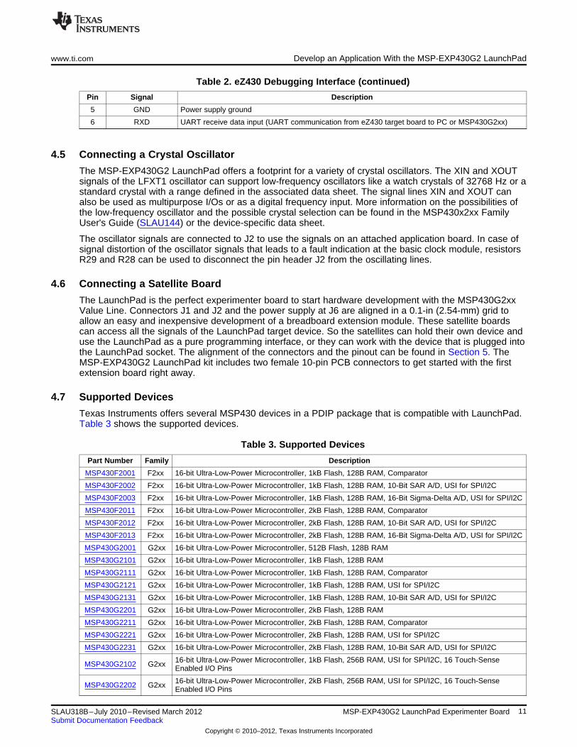
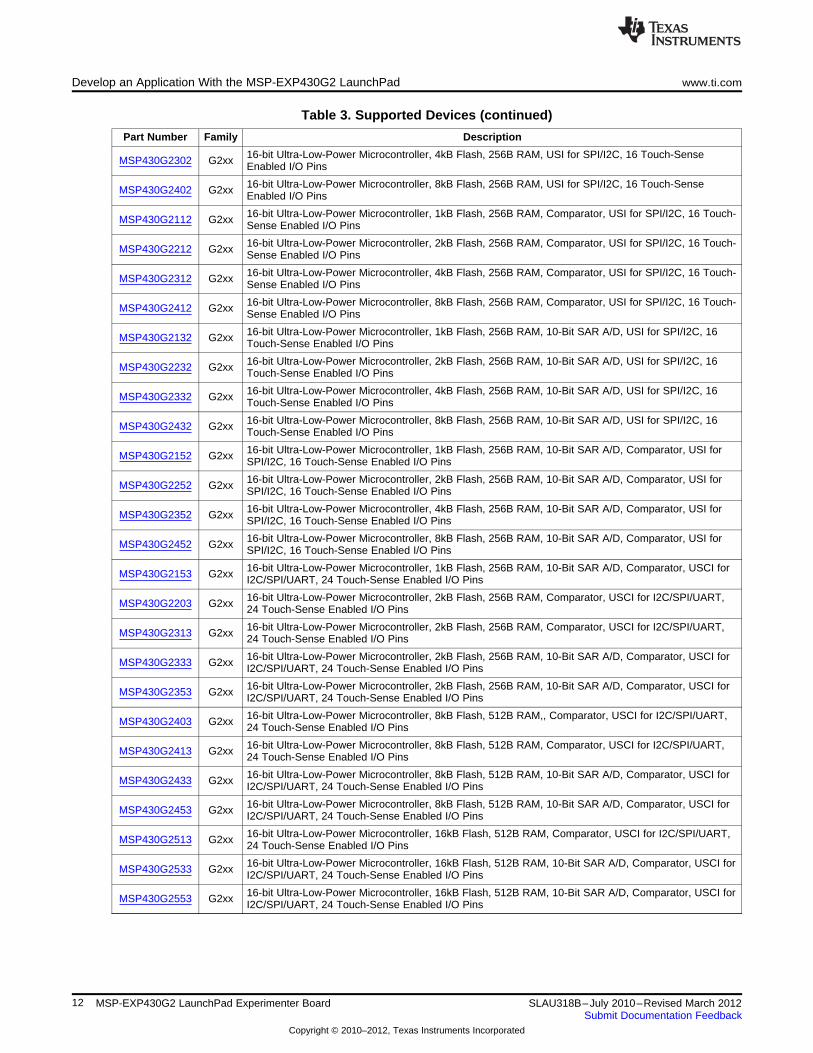
4.7 Supported Devices
Texas Instruments offers several MSP430 devices in a PDIP package that is compatible with LaunchPad.Table 3 shows the supported devices.
Table 3. Supported Devices
Part Number Family Description
MSP430F2001 F2xx 16-bit Ultra-Low-Power Microcontroller, 1kB Flash, 128B RAM, Comparator
MSP430F2002 F2xx 16-bit Ultra-Low-Power Microcontroller, 1kB Flash, 128B RAM, 10-Bit SAR A/D, USI for SPI/I2C
MSP430F2003 F2xx 16-bit Ultra-Low-Power Microcontroller, 1kB Flash, 128B RAM, 16-Bit Sigma-Delta A/D, USI for SPI/I2C
MSP430F2011 F2xx 16-bit Ultra-Low-Power Microcontroller, 2kB Flash, 128B RAM, Comparator
MSP430F2012 F2xx 16-bit Ultra-Low-Power Microcontroller, 2kB Flash, 128B RAM, 10-Bit SAR A/D, USI for SPI/I2C
MSP430F2013 F2xx 16-bit Ultra-Low-Power Microcontroller, 2kB Flash, 128B RAM, 16-Bit Sigma-Delta A/D, USI for SPI/I2C
MSP430G2001 G2xx 16-bit Ultra-Low-Power Microcontroller, 512B Flash, 128B RAM
MSP430G2101 G2xx 16-bit Ultra-Low-Power Microcontroller, 1kB Flash, 128B RAM
MSP430G2111 G2xx 16-bit Ultra-Low-Power Microcontroller, 1kB Flash, 128B RAM, Comparator
MSP430G2121 G2xx 16-bit Ultra-Low-Power Microcontroller, 1kB Flash, 128B RAM, USI for SPI/I2C
MSP430G2131 G2xx 16-bit Ultra-Low-Power Microcontroller, 1kB Flash, 128B RAM, 10-Bit SAR A/D, USI for SPI/I2C
MSP430G2201 G2xx 16-bit Ultra-Low-Power Microcontroller, 2kB Flash, 128B RAM
MSP430G2211 G2xx 16-bit Ultra-Low-Power Microcontroller, 2kB Flash, 128B RAM, Comparator
MSP430G2221 G2xx 16-bit Ultra-Low-Power Microcontroller, 2kB Flash, 128B RAM, USI for SPI/I2C
MSP430G2231 G2xx 16-bit Ultra-Low-Power Microcontroller, 2kB Flash, 128B RAM, 10-Bit SAR A/D, USI for SPI/I2C
16-bit Ultra-Low-Power Microcontroller, 1kB Flash, 256B RAM, USI for SPI/I2C, 16 Touch-SenseMSP430G2102 G2xx Enabled I/O Pins
16-bit Ultra-Low-Power Microcontroller, 2kB Flash, 256B RAM, USI for SPI/I2C, 16 Touch-SenseMSP430G2202 G2xx Enabled I/O Pins
11SLAU318B–July 2010–Revised March 2012 MSP-EXP430G2 LaunchPad Experimenter BoardSubmit Documentation Feedback
Copyright © 2010–2012, Texas Instruments Incorporated
Develop an Application With the MSP-EXP430G2 LaunchPad www.ti.com
Table 3. Supported Devices (continued)
Part Number Family Description
16-bit Ultra-Low-Power Microcontroller, 4kB Flash, 256B RAM, USI for SPI/I2C, 16 Touch-SenseMSP430G2302 G2xx Enabled I/O Pins
16-bit Ultra-Low-Power Microcontroller, 8kB Flash, 256B RAM, USI for SPI/I2C, 16 Touch-SenseMSP430G2402 G2xx Enabled I/O Pins
16-bit Ultra-Low-Power Microcontroller, 1kB Flash, 256B RAM, Comparator, USI for SPI/I2C, 16 Touch-MSP430G2112 G2xx Sense Enabled I/O Pins
16-bit Ultra-Low-Power Microcontroller, 2kB Flash, 256B RAM, Comparator, USI for SPI/I2C, 16 Touch-MSP430G2212 G2xx Sense Enabled I/O Pins
16-bit Ultra-Low-Power Microcontroller, 4kB Flash, 256B RAM, Comparator, USI for SPI/I2C, 16 Touch-MSP430G2312 G2xx Sense Enabled I/O Pins
16-bit Ultra-Low-Power Microcontroller, 8kB Flash, 256B RAM, Comparator, USI for SPI/I2C, 16 Touch-MSP430G2412 G2xx Sense Enabled I/O Pins
16-bit Ultra-Low-Power Microcontroller, 1kB Flash, 256B RAM, 10-Bit SAR A/D, USI for SPI/I2C, 16MSP430G2132 G2xx Touch-Sense Enabled I/O Pins
16-bit Ultra-Low-Power Microcontroller, 2kB Flash, 256B RAM, 10-Bit SAR A/D, USI for SPI/I2C, 16MSP430G2232 G2xx Touch-Sense Enabled I/O Pins
16-bit Ultra-Low-Power Microcontroller, 4kB Flash, 256B RAM, 10-Bit SAR A/D, USI for SPI/I2C, 16MSP430G2332 G2xx Touch-Sense Enabled I/O Pins
16-bit Ultra-Low-Power Microcontroller, 8kB Flash, 256B RAM, 10-Bit SAR A/D, USI for SPI/I2C, 16MSP430G2432 G2xx Touch-Sense Enabled I/O Pins
16-bit Ultra-Low-Power Microcontroller, 1kB Flash, 256B RAM, 10-Bit SAR A/D, Comparator, USI forMSP430G2152 G2xx SPI/I2C, 16 Touch-Sense Enabled I/O Pins
16-bit Ultra-Low-Power Microcontroller, 2kB Flash, 256B RAM, 10-Bit SAR A/D, Comparator, USI forMSP430G2252 G2xx SPI/I2C, 16 Touch-Sense Enabled I/O Pins
16-bit Ultra-Low-Power Microcontroller, 4kB Flash, 256B RAM, 10-Bit SAR A/D, Comparator, USI forMSP430G2352 G2xx SPI/I2C, 16 Touch-Sense Enabled I/O Pins
16-bit Ultra-Low-Power Microcontroller, 8kB Flash, 256B RAM, 10-Bit SAR A/D, Comparator, USI forMSP430G2452 G2xx SPI/I2C, 16 Touch-Sense Enabled I/O Pins
16-bit Ultra-Low-Power Microcontroller, 1kB Flash, 256B RAM, 10-Bit SAR A/D, Comparator, USCI forMSP430G2153 G2xx I2C/SPI/UART, 24 Touch-Sense Enabled I/O Pins
16-bit Ultra-Low-Power Microcontroller, 2kB Flash, 256B RAM, Comparator, USCI for I2C/SPI/UART,MSP430G2203 G2xx 24 Touch-Sense Enabled I/O Pins
16-bit Ultra-Low-Power Microcontroller, 2kB Flash, 256B RAM, Comparator, USCI for I2C/SPI/UART,MSP430G2313 G2xx 24 Touch-Sense Enabled I/O Pins
16-bit Ultra-Low-Power Microcontroller, 2kB Flash, 256B RAM, 10-Bit SAR A/D, Comparator, USCI forMSP430G2333 G2xx I2C/SPI/UART, 24 Touch-Sense Enabled I/O Pins
16-bit Ultra-Low-Power Microcontroller, 2kB Flash, 256B RAM, 10-Bit SAR A/D, Comparator, USCI forMSP430G2353 G2xx I2C/SPI/UART, 24 Touch-Sense Enabled I/O Pins
16-bit Ultra-Low-Power Microcontroller, 8kB Flash, 512B RAM,, Comparator, USCI for I2C/SPI/UART,MSP430G2403 G2xx 24 Touch-Sense Enabled I/O Pins
16-bit Ultra-Low-Power Microcontroller, 8kB Flash, 512B RAM, Comparator, USCI for I2C/SPI/UART,MSP430G2413 G2xx 24 Touch-Sense Enabled I/O Pins
16-bit Ultra-Low-Power Microcontroller, 8kB Flash, 512B RAM, 10-Bit SAR A/D, Comparator, USCI forMSP430G2433 G2xx I2C/SPI/UART, 24 Touch-Sense Enabled I/O Pins
16-bit Ultra-Low-Power Microcontroller, 8kB Flash, 512B RAM, 10-Bit SAR A/D, Comparator, USCI forMSP430G2453 G2xx I2C/SPI/UART, 24 Touch-Sense Enabled I/O Pins
16-bit Ultra-Low-Power Microcontroller, 16kB Flash, 512B RAM, Comparator, USCI for I2C/SPI/UART,MSP430G2513 G2xx 24 Touch-Sense Enabled I/O Pins
16-bit Ultra-Low-Power Microcontroller, 16kB Flash, 512B RAM, 10-Bit SAR A/D, Comparator, USCI forMSP430G2533 G2xx I2C/SPI/UART, 24 Touch-Sense Enabled I/O Pins
16-bit Ultra-Low-Power Microcontroller, 16kB Flash, 512B RAM, 10-Bit SAR A/D, Comparator, USCI forMSP430G2553 G2xx I2C/SPI/UART, 24 Touch-Sense Enabled I/O Pins
12 MSP-EXP430G2 LaunchPad Experimenter Board SLAU318B–July 2010–Revised March 2012Submit Documentation Feedback
Copyright © 2010–2012, Texas Instruments Incorporated
www.ti.com MSP-EXP430G2 Hardware
5 MSP-EXP430G2 Hardware
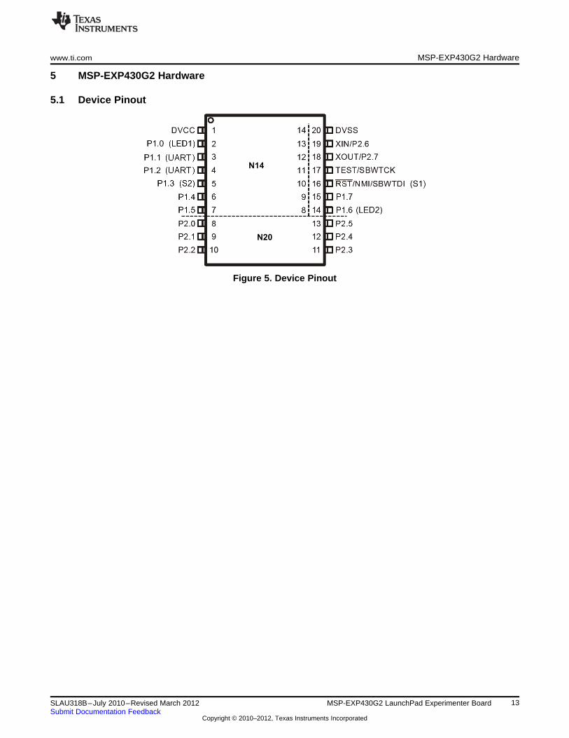
5.1 Device Pinout
Figure 5. Device Pinout
13SLAU318B–July 2010–Revised March 2012 MSP-EXP430G2 LaunchPad Experimenter BoardSubmit Documentation Feedback
Copyright © 2010–2012, Texas Instruments Incorporated
MSP-EXP430G2 Hardware www.ti.com
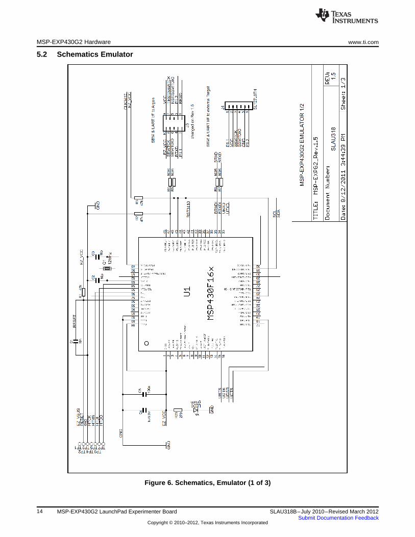
5.2 Schematics Emulator
Figure 6. Schematics, Emulator (1 of 3)
14 MSP-EXP430G2 LaunchPad Experimenter Board SLAU318B–July 2010–Revised March 2012Submit Documentation Feedback
Copyright © 2010–2012, Texas Instruments Incorporated
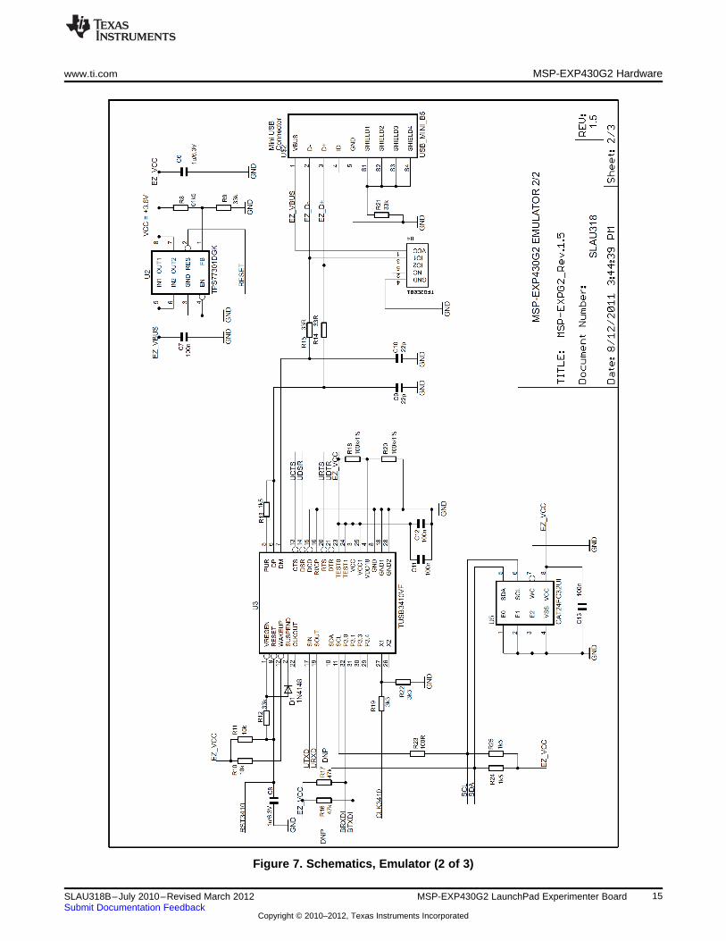
www.ti.com MSP-EXP430G2 Hardware
Figure 7. Schematics, Emulator (2 of 3)
15SLAU318B–July 2010–Revised March 2012 MSP-EXP430G2 LaunchPad Experimenter BoardSubmit Documentation Feedback
Copyright © 2010–2012, Texas Instruments Incorporated
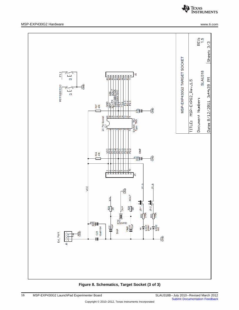
MSP-EXP430G2 Hardware www.ti.com
Figure 8. Schematics, Target Socket (3 of 3)
16 MSP-EXP430G2 LaunchPad Experimenter Board SLAU318B–July 2010–Revised March 2012Submit Documentation Feedback
Copyright © 2010–2012, Texas Instruments Incorporated
www.ti.com MSP-EXP430G2 Hardware
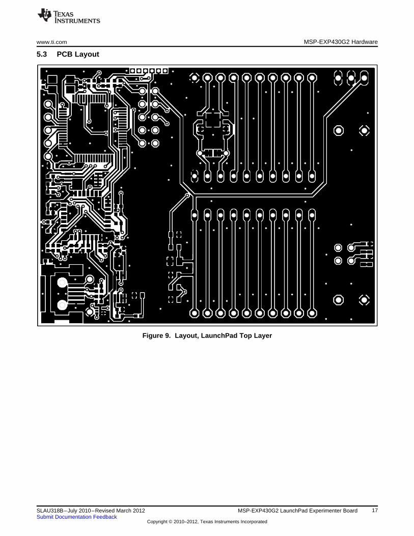
5.3 PCB Layout
Figure 9. Layout, LaunchPad Top Layer
17SLAU318B–July 2010–Revised March 2012 MSP-EXP430G2 LaunchPad Experimenter BoardSubmit Documentation Feedback
Copyright © 2010–2012, Texas Instruments Incorporated
MSP-EXP430G2 Hardware www.ti.com
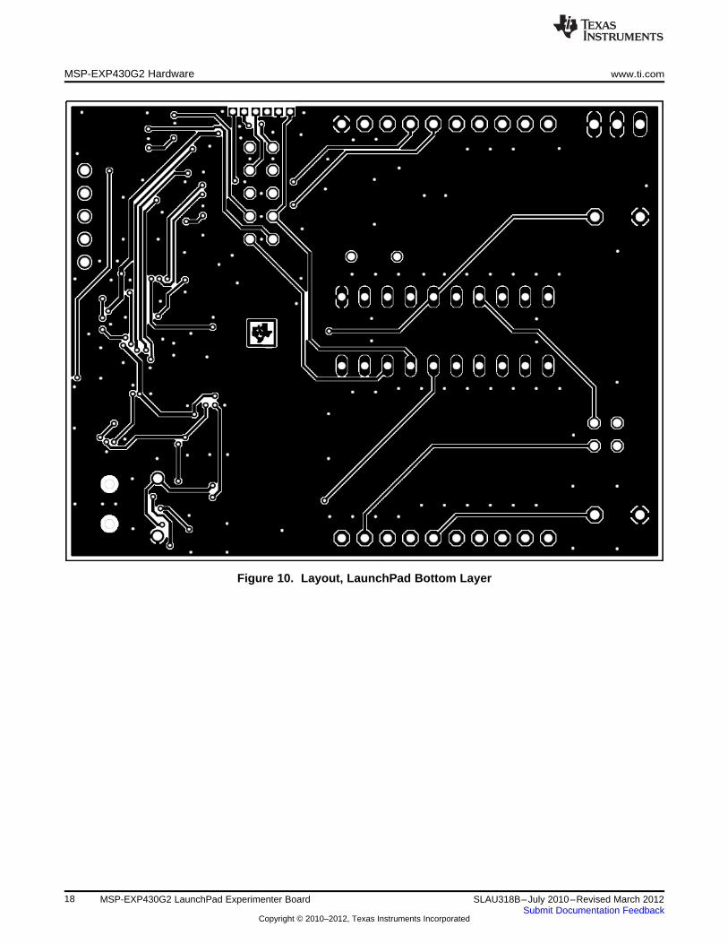
Figure 10. Layout, LaunchPad Bottom Layer
18 MSP-EXP430G2 LaunchPad Experimenter Board SLAU318B–July 2010–Revised March 2012Submit Documentation Feedback
Copyright © 2010–2012, Texas Instruments Incorporated
www.ti.com MSP-EXP430G2 Hardware
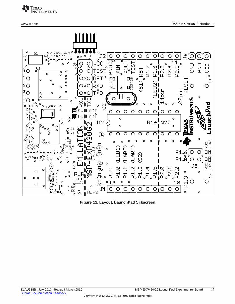
Figure 11. Layout, LaunchPad Silkscreen
19SLAU318B–July 2010–Revised March 2012 MSP-EXP430G2 LaunchPad Experimenter BoardSubmit Documentation Feedback
Copyright © 2010–2012, Texas Instruments Incorporated
MSP-EXP430G2 Hardware www.ti.com
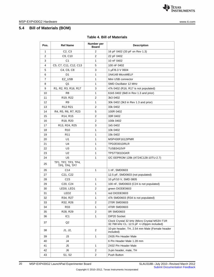
5.4 Bill of Materials (BOM)
Table 4. Bill of Materials
Number perPos. Ref Name DescriptionBoard
1 C2, C3 2 16 pF 0402 (33 pF on Rev 1.3)
2 C9, C10 2 22 pF 0402
3 C1 1 10 nF 0402
4 C5, C7, C11, C12, C13 5 100 nF 0402
5 C4, C6, C8 3 1 µF/6.3 V 0604
6 D1 1 1N4148 MicroMELF
7 EZ_USB 1 Mini USB connector
8 Q1 1 SMD Oscillator 12 MHz
9 R1, R2, R3, R16, R17 3 47k 0402 (R16, R17 is not populated)
10 R8 1 61k5 0402 (6k8 in Rev 1.3 and prior)
11 R19, R22 2 3k3 0402
12 R9 1 30k 0402 (3k3 in Rev 1.3 and prior)
13 R12 R21 2 33k 0402
14 R4, R5, R6, R7, R23 5 100R 0402
15 R14, R15 2 33R 0402
16 R18, R20 2 100k 0402
17 R13, R24, R25 3 1k5 0402
18 R10 1 10k 0402
19 R11 1 15k 0402
20 U1 1 MSP430F1612IPMR
21 U4 1 TPD2E001DRLR
22 U3 1 TUSB3410VF
23 U2 1 TPS77301DGKR
24 U5 1 I2C EEPROM 128k (AT24C128-10TU-2.7)
TP1, TP2, TP3, TP4,25 TP5, TP6, TP7
26 C14 1 1 nF, SMD0603
27 C21, C22 12.5 pF, SMD0603 (not populated)
28 C23 1 10 µF/10 V, SMD 0805
29 C20, C24 1 100 nF, SMD0603 (C24 is not populated)
30 LED0, LED1 2 green DIODE0603
31 LED2 1 red DIODE0603
32 R34, R27 1 47k SMD0603 (R34 is not populated)
33 R32, R26 2 270R SMD0603
34 R33 1 470R SMD0603
35 R28, R29 2 0R SMD0603
36 IC1 1 DIP20 Socket
Clock Crystal 32 kHz (Micro Crystal MS3V-T1R37 Q2 32.768 kHz CL: 12.5 pF +/-20ppm included)
10-pin header, TH, 2.54 mm Male (Female header38 J1, J2, 2 included)
39 J3 1 2X05 Pin Header Male
40 J4 6 Pin Header Male 1.28 mm
41 J5 1 2X02 Pin Header Male
42 J6 2 3-pin header, male, TH
43 S1, S2 2 Push Button
20 MSP-EXP430G2 LaunchPad Experimenter Board SLAU318B–July 2010–Revised March 2012Submit Documentation Feedback
Copyright © 2010–2012, Texas Instruments Incorporated

www.ti.com Suggested Reading
6 Suggested Reading
The primary sources of MSP430™ information are the device-specific data sheets and the family user'sguides. The most up-to-date versions of those documents can be found at the Texas Instruments MSP430page or the MSP430 LaunchPad wiki.
http://www.ti.com/msp430, http://processors.wiki.ti.com/index.php/MSP430_LaunchPad_(MSP-EXP430G2)
To get an inside view of the supporting IDEs like CCS and IAR, download the latest version from the webpages above and read the included user's guides and documentation inside the installation folder.Documents describing the IAR tools (Workbench/C-SPY, the assembler, the C compiler, the linker, andthe library) are located in common\doc and 430\doc. All necessary CCS documents can be found in themsp430\doc folder in the CCS installation path. The FET user's guide also includes detailed informationon how to set up a project for the MSP430 using IAR or CCS, and it is included in most of the IDEreleases and on the TI MSP430 side.
7 Frequently Asked Questions (FAQ)1. Can other programming tools like the MSP-FET430UIF interface the MSP-EXP430G2 LaunchPad
socket device?
The LaunchPad experimenter board works with any programming tool that supports the 2-wire Spy-Bi-Wire interface. Both the MSP430 USB FET (MSP-FET430UIF) and the Gang Programmer (MSP-GANG430) support these devices, but the connection must be made directly to the dedicated Spy-Bi-Wire ports. See MSP-FET430 Flash Emulation Tool User's Guide (SLAU138) for details on usingMSP430 USB FET and the Gang Programmer for a 2-wire Spy-Bi-Wire interface. Do not try to connectthe standard JTAG connector to the MSP-EXP430G2 pinheads, as this could result in damage to theattached hardware.
2. Does the MSP-EXP430G2 support fuse blow?
The MSP-EXP430G2 LaunchPad experimenter board onboard debugging interface lacks the JTAGsecurity fuse-blow capability. To ensure firmware security on devices going to production, the USBFlash Emulation Tool or the Gang Production Programmer, which support the fuse-blow feature, arerecommended.
3. What versions of IAR Embedded Workbench and Code Composer Studio are supported?
The MSP-EXP430 LaunchPad hardware is supported by IAR Embedded Workbench KickStart Version6.00 or higher and Code Composer Studio v4 or higher. To download the software and for moreinformation on the supported software visit the LaunchPad Wiki page.http://processors.wiki.ti.com/index.php/MSP430_LaunchPad_(MSP-EXP430G2)
4. What are the part numbers for the connectors between the LaunchPad emulator board and the othereZ430 target boards?
Header: MALE CONN HEADER .050" 6POS PCB R/A (for example, Digi-Key: S9016E-06-ND)
Socket: FEMALE CONN HEADER .050" 6POS PCB R/A (for example, Digi-Key: S9010E-06-ND)
5. I am not able to select the MSP430 Application UART and cannot receive data.
Ensure that the Application UART driver is correctly installed. This is done by installing either IAREmbedded Workbench or Code Composer Studio v4.
To determine if the driver is correctly installed:a. Plug in the MSP-EXP430G2 LaunchPad with the included Mini USB cable.b. Right click My Computer and select Properties.c. Select the Hardware tab and click on Device Manager.d. Under Ports (COM & LPT) should be an entry for "MSP430 Application UART (COM xx)".
If the entry is there, but no characters are received, reconnect the LaunchPad to the PC and restart theapplication to reload the drivers. If the Application UART is not listed, install the driver by following theinstructions in Section 2.2.
6. The device is not answering to any communication, JTAG or UART.
If you are experiencing difficulties in communicating to the attached MSP430 target device, eventhough all the communication drivers for the MSP-EXP430G2 are loaded correctly, the emulator isprobably set to a wrong communication state. This can be fixed by reconnecting the LaunchPad
21SLAU318B–July 2010–Revised March 2012 MSP-EXP430G2 LaunchPad Experimenter BoardSubmit Documentation Feedback
Copyright © 2010–2012, Texas Instruments Incorporated
Frequently Asked Questions (FAQ) www.ti.com
Experimenter Board and restarting the communicating application. Also make sure that all the jumperson J3 are connected properly between the emulator and the target device. On revision 1.5 and newer,the orientation of the UART jumpers must align with the software implementation on the target device.
7. I soldered the 32-kHz crystal to the board and the oscillation is not starting.
The MSP430 driving capabilities for the low-frequency crystal is limited, because it is designed for low-power applications. To ensure proper operation, the load on these pins must be as small as possible,the matching capacitors (12.5 pF for 32.768 kHz) for the crystal must be soldered to the board, and theresistors R28 and R29 must be removed. Trying to measure the frequency of the oscillation with anoscilloscope typically disturbs the oscillation.
8. The power consumption of the board is much higher than specified in the device data sheet, or I amnot measuring a current at all.
The MSP430 device inside of the LaunchPad socket can be powered with an external power supply atheader J6 or J4. To measure the power consumption in this mode, the VCC jumper, usually used tomeasure the power consumption, must be removed, and the current must be measured directly at thepower supply. If the jumper J3 is not removed, the emulator circuitry of the LaunchPad is powered aswell. Measuring the current consumption during a debug session is not possible, because the crosscurrent through the JTAG connection influences the measurement. The most accurate results areachieved with all jumpers on J3 removed. If the measurement is still not matching the data sheetparameters, make sure that the code is aligned with all the power saving recommendations on the website MSP430™ - The World's Lowest Power MCU.
LaunchPad revisions 1.3 and 1.4 come with R34 populated. The 47-kΩ resistor is used as a pullup forthe button S2. If the port P1.3 is driven to ground, as suggested to keep the power consumption down,the pullup resistor generates an additional current of approximately 77 µA. To reduce the powerconsumption, the port should stay in input mode or the resistor should be removed if button S2 is notused. The internal pullup of the MSP430G2xx can be used instead.
22 MSP-EXP430G2 LaunchPad Experimenter Board SLAU318B–July 2010–Revised March 2012Submit Documentation Feedback
Copyright © 2010–2012, Texas Instruments Incorporated
IMPORTANT NOTICE
Texas Instruments Incorporated and its subsidiaries (TI) reserve the right to make corrections, modifications, enhancements, improvements,and other changes to its products and services at any time and to discontinue any product or service without notice. Customers shouldobtain the latest relevant information before placing orders and should verify that such information is current and complete. All products aresold subject to TI’s terms and conditions of sale supplied at the time of order acknowledgment.
TI warrants performance of its hardware products to the specifications applicable at the time of sale in accordance with TI’s standardwarranty. Testing and other quality control techniques are used to the extent TI deems necessary to support this warranty. Except wheremandated by government requirements, testing of all parameters of each product is not necessarily performed.
TI assumes no liability for applications assistance or customer product design. Customers are responsible for their products andapplications using TI components. To minimize the risks associated with customer products and applications, customers should provideadequate design and operating safeguards.
TI does not warrant or represent that any license, either express or implied, is granted under any TI patent right, copyright, mask work right,or other TI intellectual property right relating to any combination, machine, or process in which TI products or services are used. Informationpublished by TI regarding third-party products or services does not constitute a license from TI to use such products or services or awarranty or endorsement thereof. Use of such information may require a license from a third party under the patents or other intellectualproperty of the third party, or a license from TI under the patents or other intellectual property of TI.
Reproduction of TI information in TI data books or data sheets is permissible only if reproduction is without alteration and is accompaniedby all associated warranties, conditions, limitations, and notices. Reproduction of this information with alteration is an unfair and deceptivebusiness practice. TI is not responsible or liable for such altered documentation. Information of third parties may be subject to additionalrestrictions.
Resale of TI products or services with statements different from or beyond the parameters stated by TI for that product or service voids allexpress and any implied warranties for the associated TI product or service and is an unfair and deceptive business practice. TI is notresponsible or liable for any such statements.
TI products are not authorized for use in safety-critical applications (such as life support) where a failure of the TI product would reasonablybe expected to cause severe personal injury or death, unless officers of the parties have executed an agreement specifically governingsuch use. Buyers represent that they have all necessary expertise in the safety and regulatory ramifications of their applications, andacknowledge and agree that they are solely responsible for all legal, regulatory and safety-related requirements concerning their productsand any use of TI products in such safety-critical applications, notwithstanding any applications-related information or support that may beprovided by TI. Further, Buyers must fully indemnify TI and its representatives against any damages arising out of the use of TI products insuch safety-critical applications.
TI products are neither designed nor intended for use in military/aerospace applications or environments unless the TI products arespecifically designated by TI as military-grade or "enhanced plastic." Only products designated by TI as military-grade meet militaryspecifications. Buyers acknowledge and agree that any such use of TI products which TI has not designated as military-grade is solely atthe Buyer's risk, and that they are solely responsible for compliance with all legal and regulatory requirements in connection with such use.
TI products are neither designed nor intended for use in automotive applications or environments unless the specific TI products aredesignated by TI as compliant with ISO/TS 16949 requirements. Buyers acknowledge and agree that, if they use any non-designatedproducts in automotive applications, TI will not be responsible for any failure to meet such requirements.
Following are URLs where you can obtain information on other Texas Instruments products and application solutions:
Products Applications
Audio www.ti.com/audio Automotive and Transportation www.ti.com/automotive
Amplifiers amplifier.ti.com Communications and Telecom www.ti.com/communications
Data Converters dataconverter.ti.com Computers and Peripherals www.ti.com/computers
DLP® Products www.dlp.com Consumer Electronics www.ti.com/consumer-apps
DSP dsp.ti.com Energy and Lighting www.ti.com/energy
Clocks and Timers www.ti.com/clocks Industrial www.ti.com/industrial
Interface interface.ti.com Medical www.ti.com/medical
Logic logic.ti.com Security www.ti.com/security
Power Mgmt power.ti.com Space, Avionics and Defense www.ti.com/space-avionics-defense
Microcontrollers microcontroller.ti.com Video and Imaging www.ti.com/video
RFID www.ti-rfid.com
OMAP Mobile Processors www.ti.com/omap
Wireless Connectivity www.ti.com/wirelessconnectivity
TI E2E Community Home Page e2e.ti.com
Mailing Address: Texas Instruments, Post Office Box 655303, Dallas, Texas 75265Copyright © 2012, Texas Instruments Incorporated