Embed Size (px)
Citation preview
1SLAU678B–March 2016–Revised September 2019Submit Documentation Feedback
Copyright © 2016–2019, Texas Instruments Incorporated
MSP430FR5994 LaunchPad™ Development Kit (MSP‑EXP430FR5994)
User's GuideSLAU678B–March 2016–Revised September 2019
MSP430FR5994 LaunchPad™ Development Kit(MSP‑‑EXP430FR5994)
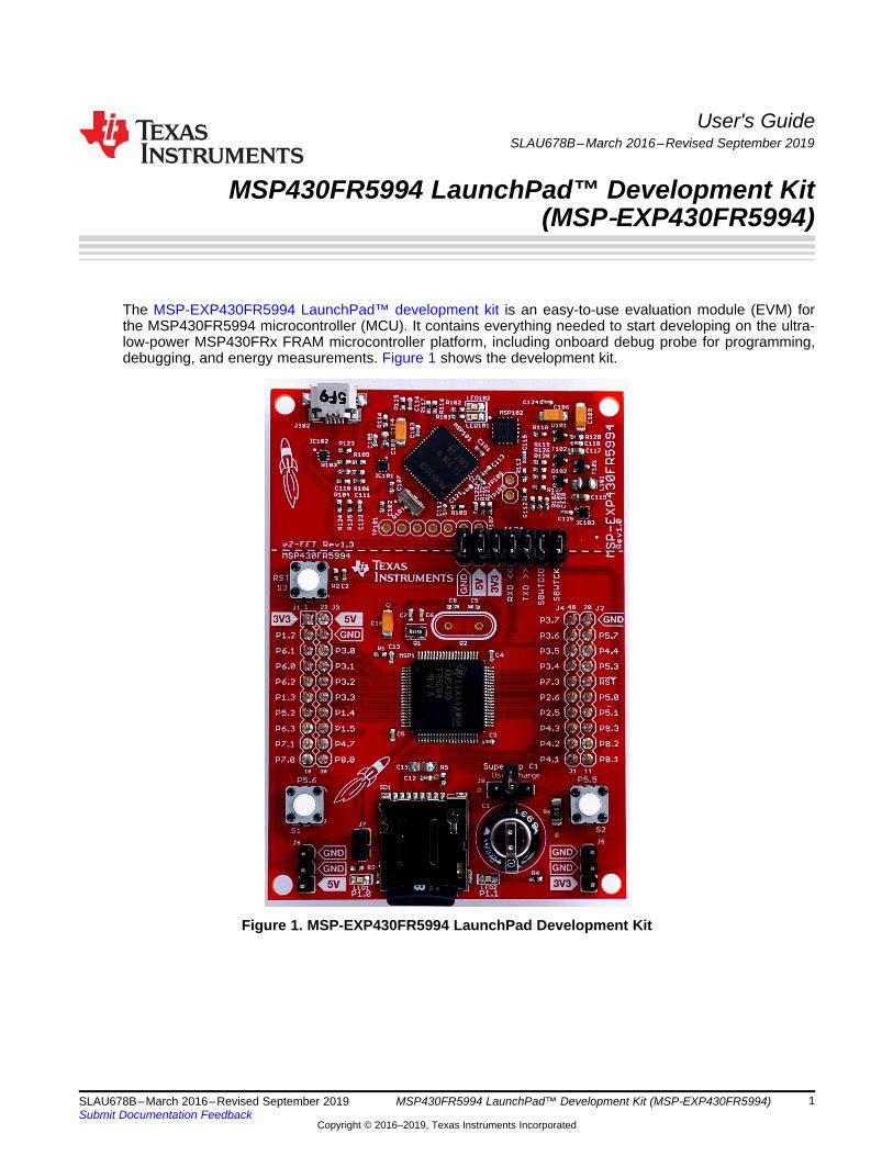
The MSP-EXP430FR5994 LaunchPad™ development kit is an easy-to-use evaluation module (EVM) forthe MSP430FR5994 microcontroller (MCU). It contains everything needed to start developing on the ultra-low-power MSP430FRx FRAM microcontroller platform, including onboard debug probe for programming,debugging, and energy measurements. Figure 1 shows the development kit.
Figure 1. MSP-EXP430FR5994 LaunchPad Development Kit
www.ti.com
2 SLAU678B–March 2016–Revised September 2019Submit Documentation Feedback
Copyright © 2016–2019, Texas Instruments Incorporated
MSP430FR5994 LaunchPad™ Development Kit (MSP‑EXP430FR5994)
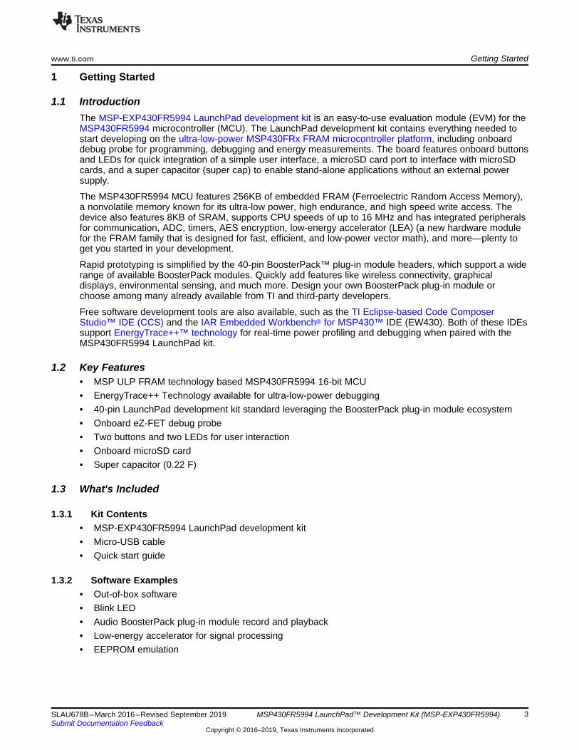
Contents1 Getting Started ............................................................................................................... 32 Hardware...................................................................................................................... 53 Software Examples ........................................................................................................ 164 Resources ................................................................................................................... 255 FAQ .......................................................................................................................... 326 Schematics.................................................................................................................. 33
List of Figures
1 MSP-EXP430FR5994 LaunchPad Development Kit .................................................................... 12 MSP-EXP430FR5994 Overview ........................................................................................... 53 MSP-EXP430FR5994 Block Diagram..................................................................................... 64 MSP430FR5994 Pinout..................................................................................................... 75 eZ-FET Debug Probe ....................................................................................................... 86 eZ-FET Isolation Jumper Block Diagram ............................................................................... 107 Application Backchannel UART in Device Manager................................................................... 108 MSP-EXP430FR5994 Power Block Diagram........................................................................... 129 MSP-EXP430FR5994 Super Cap Power Block Diagram ............................................................. 1310 BoosterPack Plug-in Module Checker Tool............................................................................. 1511 LaunchPad Development Kit to BoosterPack Plug-in Module Connector Pinout.................................. 1612 MSP-EXP430FR5994 Out-of-Box Demo GUI .......................................................................... 1813 Live Temperature Mode ................................................................................................... 1914 FRAM Log Mode ........................................................................................................... 2015 Record ....................................................................................................................... 2216 Playback..................................................................................................................... 2317 Alternate Microphone Configuration ..................................................................................... 2418 EEPROM SPI Interface Block Diagram ................................................................................. 2519 EEPROM I2C Interface Block Diagram .................................................................................. 2520 TI Resource Explorer Cloud .............................................................................................. 2621 CCS Cloud .................................................................................................................. 2722 Directing the Project>Import Function to the Demo Project .......................................................... 2823 When CCS Has Found the Project ...................................................................................... 2824 Using TI Resource Explorer to Browse MSP-EXP430FR5994 in MSPWare ...................................... 3025 Schematics (1 of 7) ........................................................................................................ 3326 Schematics (2 of 7) ........................................................................................................ 3427 Schematics (3 of 7) ........................................................................................................ 3528 Schematics (4 of 7) ........................................................................................................ 3629 Schematics (5 of 7) ........................................................................................................ 3730 Schematics (6 of 7) ........................................................................................................ 3831 Schematics (7 of 7) ........................................................................................................ 39
TrademarksLaunchPad, BoosterPack, Code Composer Studio, MSP430, EnergyTrace++, EnergyTrace, E2E aretrademarks of Texas Instruments.IAR Embedded Workbench, C-SPY are registered trademarks of IAR Systems.All other trademarks are the property of their respective owners.
www.ti.com Getting Started
3SLAU678B–March 2016–Revised September 2019Submit Documentation Feedback
Copyright © 2016–2019, Texas Instruments Incorporated
MSP430FR5994 LaunchPad™ Development Kit (MSP‑EXP430FR5994)
1 Getting Started
1.1 IntroductionThe MSP-EXP430FR5994 LaunchPad development kit is an easy-to-use evaluation module (EVM) for theMSP430FR5994 microcontroller (MCU). The LaunchPad development kit contains everything needed tostart developing on the ultra-low-power MSP430FRx FRAM microcontroller platform, including onboarddebug probe for programming, debugging and energy measurements. The board features onboard buttonsand LEDs for quick integration of a simple user interface, a microSD card port to interface with microSDcards, and a super capacitor (super cap) to enable stand-alone applications without an external powersupply.
The MSP430FR5994 MCU features 256KB of embedded FRAM (Ferroelectric Random Access Memory),a nonvolatile memory known for its ultra-low power, high endurance, and high speed write access. Thedevice also features 8KB of SRAM, supports CPU speeds of up to 16 MHz and has integrated peripheralsfor communication, ADC, timers, AES encryption, low-energy accelerator (LEA) (a new hardware modulefor the FRAM family that is designed for fast, efficient, and low-power vector math), and more—plenty toget you started in your development.
Rapid prototyping is simplified by the 40-pin BoosterPack™ plug-in module headers, which support a widerange of available BoosterPack modules. Quickly add features like wireless connectivity, graphicaldisplays, environmental sensing, and much more. Design your own BoosterPack plug-in module orchoose among many already available from TI and third-party developers.
Free software development tools are also available, such as the TI Eclipse-based Code ComposerStudio™ IDE (CCS) and the IAR Embedded Workbench® for MSP430™ IDE (EW430). Both of these IDEssupport EnergyTrace++™ technology for real-time power profiling and debugging when paired with theMSP430FR5994 LaunchPad kit.
1.2 Key Features• MSP ULP FRAM technology based MSP430FR5994 16-bit MCU• EnergyTrace++ Technology available for ultra-low-power debugging• 40-pin LaunchPad development kit standard leveraging the BoosterPack plug-in module ecosystem• Onboard eZ-FET debug probe• Two buttons and two LEDs for user interaction• Onboard microSD card• Super capacitor (0.22 F)
1.3 What's Included
1.3.1 Kit Contents• MSP-EXP430FR5994 LaunchPad development kit• Micro-USB cable• Quick start guide
1.3.2 Software Examples• Out-of-box software• Blink LED• Audio BoosterPack plug-in module record and playback• Low-energy accelerator for signal processing• EEPROM emulation
Getting Started www.ti.com
4 SLAU678B–March 2016–Revised September 2019Submit Documentation Feedback
Copyright © 2016–2019, Texas Instruments Incorporated
MSP430FR5994 LaunchPad™ Development Kit (MSP‑EXP430FR5994)
1.4 First Steps: Out-of-Box ExperienceAn easy way to get familiar with the EVM is by using its preprogrammed out-of-box code. It demonstratessome key features from a user level.
1.4.1 Connecting to the ComputerConnect the LaunchPad development kit using the included USB cable to a computer. A green power LEDshould illuminate. For proper operation, drivers are needed. TI recommends installing the drivers byinstalling an IDE such as TI CCS or IAR EW430. Drivers are also available at ti.com/MSPdrivers.
1.4.2 Running the Out-of-Box DemoWhen connected to the computer, the LaunchPad development kit powers up. Press and hold the S1 andS2 buttons simultaneously to select a new mode. See Section 3.1 for a detailed explanation of eachmode.
1.4.2.1 Live Temperature ModeThis mode provides live temperature data streaming to the PC GUI. You can influence the temperature ofthe device and see changes on the GUI.
1.4.2.2 FRAM Data Log ModeThis mode shows the FRAM data logging capabilities of the MSP430FR5994. After starting this mode, theLaunchPad development kit wakes up every five seconds from sleep mode (indicated by LED blink) to logboth temperature and input voltage values. After reconnecting to the GUI, these values can be uploadedand graphed in the GUI.
1.4.2.3 SD Card Data Log ModeThis mode shows the data logging capabilities of the MSP430FR5994 while interfacing with an SD card.After starting this mode, the LaunchPad development kit wakes up every five seconds from sleep mode(indicated by LED blink) to log both temperature and input voltage values. After reconnecting to the GUI,these values can be uploaded and graphed in the GUI.
1.5 Next Steps: Looking Into the Provided CodeAfter the EVM features have been explored, the fun can begin. It's time to open an integrateddevelopment environment and start editing the code examples. See Section 4 for available IDEs andwhere to download them.
The quickest way to get started using the LaunchPad development kit is to use TI's Cloud DevelopmentTools. The cloud-based Resource Explorer provides access to all of the examples and resources inMSPWare. Code Composer Studio Cloud is a simple cloud-based IDE that enables developing andrunning applications on the LaunchPad development kit.
The out-of-box source code and more code examples are provided and available on the download page.Code is licensed under BSD, and TI encourages reuse and modifications to fit specific needs.
Section 3 describes all functions in detail and provides a project structure to help familiarize you with thecode.
With the onboard eZ-FET debug probe debugging and downloading new code is simple. A USBconnection between the EVM and a PC through the provided USB cable is all that is needed.
www.ti.com Hardware
5SLAU678B–March 2016–Revised September 2019Submit Documentation Feedback
Copyright © 2016–2019, Texas Instruments Incorporated
MSP430FR5994 LaunchPad™ Development Kit (MSP‑EXP430FR5994)
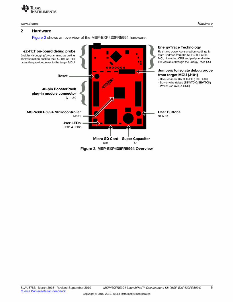
2 HardwareFigure 2 shows an overview of the MSP-EXP430FR5994 hardware.
Figure 2. MSP-EXP430FR5994 Overview
Target device
MSP430FR5994
Crystal
32.768 kHz
Micro-B
USB
3.3-V
LDO
ESD
protection
Debug
MCU
LED
red, green
Crystal
4 MHz
UART, SBW to target
User interface
2 buttons, 2 LEDs
40-pin LaunchPad
standard headers
Power to target
Reset
button Super capacitor
EnergyTrace
microSD Card
Hardware www.ti.com
6 SLAU678B–March 2016–Revised September 2019Submit Documentation Feedback
Copyright © 2016–2019, Texas Instruments Incorporated
MSP430FR5994 LaunchPad™ Development Kit (MSP‑EXP430FR5994)
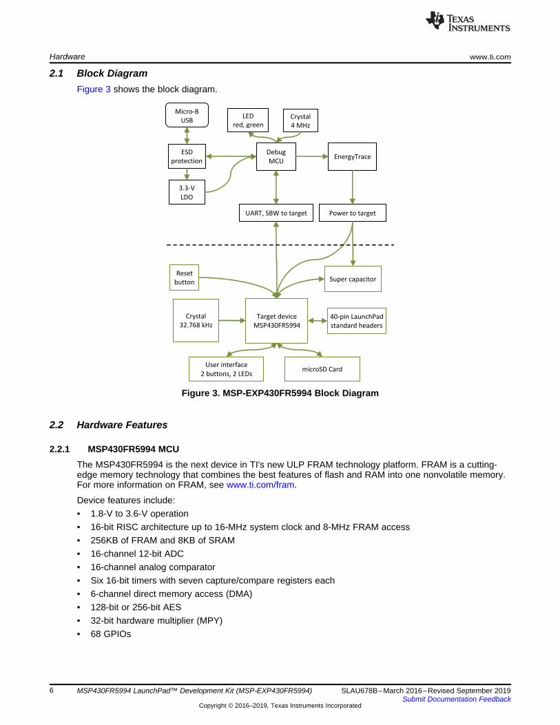
2.1 Block DiagramFigure 3 shows the block diagram.
Figure 3. MSP-EXP430FR5994 Block Diagram
2.2 Hardware Features
2.2.1 MSP430FR5994 MCUThe MSP430FR5994 is the next device in TI's new ULP FRAM technology platform. FRAM is a cutting-edge memory technology that combines the best features of flash and RAM into one nonvolatile memory.For more information on FRAM, see www.ti.com/fram.
Device features include:• 1.8-V to 3.6-V operation• 16-bit RISC architecture up to 16-MHz system clock and 8-MHz FRAM access• 256KB of FRAM and 8KB of SRAM• 16-channel 12-bit ADC• 16-channel analog comparator• Six 16-bit timers with seven capture/compare registers each• 6-channel direct memory access (DMA)• 128-bit or 256-bit AES• 32-bit hardware multiplier (MPY)• 68 GPIOs
1
2
3
4
5
6
7
8
9
10
11
12
13
14
15
16
17
18
19
20
21
DV
SS
3
22
DVCC2
23 24 25 26 27 28 29 30 31 32 33 34
P5.0/UCB1SIMO/UCB1SDA
35 36 37 38 39 40
41
42
43
44
45
46
47
48
49
50
51
52
53
54
55
56
57
58
59
60
61626364
DV
CC
1
65666768697071727374757677787980
P1.4/TB0.1/UCA0STE/A4/C4
P1.0/TA0.1/DMAE0/RTCCLK/A0/C0/VREF-/VeREF-
P1.1/TA0.2/TA1CLK/COUT/A1/C1/VREF+/VeREF+
P1.2/TA1.1/TA0CLK/COUT/A2/C2
P3.0/A12/C12
P3.1/A13/C13
P3.2/A14/C14
P3.3/A15/C15
P1.3/TA1.2/UCB0STE/A3/C3
P1.5/TB0.2/UCA0CLK/A5/C5
P4.7
PJ.0
/TD
O/T
B0
OU
TH
/SM
CL
K/S
RS
CG
1/C
6
PJ.1
/TD
I/T
CL
K/M
CL
K/S
RS
CG
0/C
7
PJ.2
/TM
S/A
CL
K/S
RO
SC
OF
F/C
8
PJ.3
/TC
K/S
RC
PU
OF
F/C
9
P4
.0/A
8
P4
.1/A
9
P4
.2/A
10
P4
.3/A
11
P2
.5/T
B0
.0/U
CA
1T
XD
/UC
A1
SIM
O
P2
.6/T
B0
.1/U
CA
1R
XD
/UC
A1
SO
MI
TE
ST
/SB
WT
CK
RS
T/N
MI/
SB
WT
DIO
P2.0/TB0.6/UCA0TXD/UCA0SIMO/TB0CLK/ACLK
P2.1/TB0.0/UCA0RXD/UCA0SOMI
P2.2/TB0.2/UCB0CLK
P3.4/TB0.3/SMCLK
P3.5/TB0.4/COUT
P3.6/TB0.5
P3.7/TB0.6
P1.6/TB0.3/UCB0SIMO/UCB0SDA/TA0.0
P1.7/TB0.4/UCB0SOMI/UCB0SCL/TA1.0
P4.4/TB0.5
P4.5
P4.6
DVSS1
P2
.7
P2
.3/T
A0
.0/U
CA
1S
TE
/A6
/C1
0
AV
SS
3
PJ.6
/HF
XIN
PJ.7
/HF
XO
UT
AV
SS
2
PJ.4
/LF
XIN
PJ.5
/LF
XO
UT
AV
SS
1
AV
CC
1
P2
.4/T
A1
.0/U
CA
1C
LK
/A7
/C11
DVSS2
P5.1/UCB1SOMI/UCB1SCL
P5.2/UCB1CLK/TA4CLK
P5.3/UCB1STE
P5
.4/U
CA
2T
XD
/UC
A2
SIM
O/T
B0
OU
TH
P5
.5/U
CA
2R
XD
/UC
A2
SO
MI/
AC
LK
P5
.6/U
CA
2C
LK
/TA
4.0
/SM
CL
K
P5
.7/U
CA
2S
TE
/TA
4.1
/MC
LK
P8.0
P6.0/UCA3TXD/UCA3SIMO
P6.1/UCA3RXD/UCA3SOMI
P6.2/UCA3CLK
P6.3/UCA3STE
P8.1
DV
CC
3
P6
.4/U
CB
3S
IMO
/UC
B3
SD
A
P6
.5/U
CB
3S
OM
I/U
CB
3S
CL
P6
.6/U
CB
3C
LK
P6
.7/U
CB
3S
TE
P8.2
P8.3
P7.0/UCB2SIMO/UCB2SDA
P7
.2/U
CB
2C
LK
P7
.3/U
CB
2S
TE
/TA
4.1
P7.1/UCB2SOMI/UCB2SCL
P7
.4/T
A4
.0/A
16
P7
.6/A
18
P7
.7/A
19
P7
.5/A
17
www.ti.com Hardware
7SLAU678B–March 2016–Revised September 2019Submit Documentation Feedback
Copyright © 2016–2019, Texas Instruments Incorporated
MSP430FR5994 LaunchPad™ Development Kit (MSP‑EXP430FR5994)
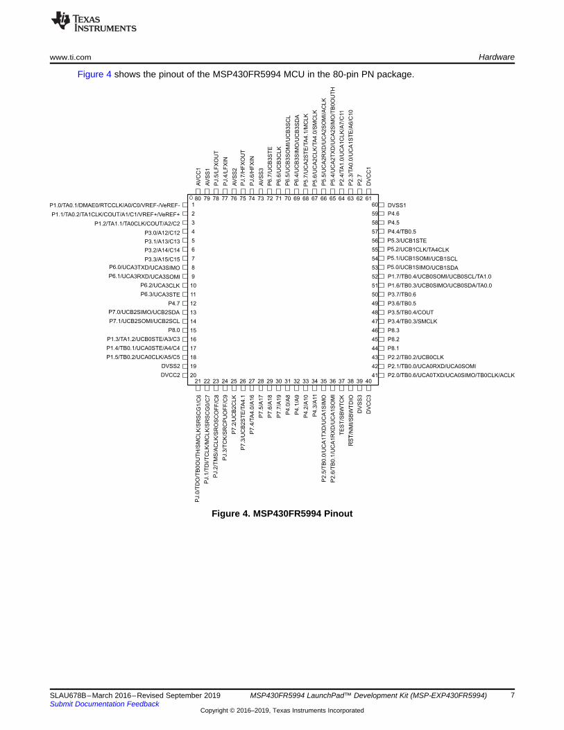
Figure 4 shows the pinout of the MSP430FR5994 MCU in the 80-pin PN package.
Figure 4. MSP430FR5994 Pinout
Hardware www.ti.com
8 SLAU678B–March 2016–Revised September 2019Submit Documentation Feedback
Copyright © 2016–2019, Texas Instruments Incorporated
MSP430FR5994 LaunchPad™ Development Kit (MSP‑EXP430FR5994)
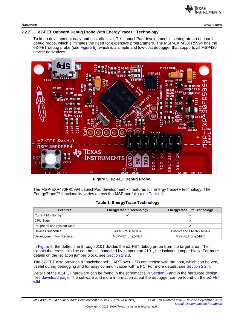
2.2.2 eZ-FET Onboard Debug Probe With EnergyTrace++ TechnologyTo keep development easy and cost effective, TI's LaunchPad development kits integrate an onboarddebug probe, which eliminates the need for expensive programmers. The MSP-EXP430FR5994 has theeZ-FET debug probe (see Figure 5), which is a simple and low-cost debugger that supports all MSP430device derivatives.
Figure 5. eZ-FET Debug Probe
The MSP-EXP430FR5994 LaunchPad development kit features full EnergyTrace++ technology. TheEnergyTrace™ functionality varies across the MSP portfolio (see Table 1).
Table 1. EnergyTrace Technology
Features EnergyTrace™ Technology EnergyTrace++™ TechnologyCurrent Monitoring ✓ ✓CPU State ✓Peripheral and System State ✓Devices Supported All MSP430 MCUs FR59xx and FR69xx MCUsDevelopment Tool Required MSP-FET or eZ-FET MSP-FET or eZ-FET
In Figure 5, the dotted line through J101 divides the eZ-FET debug probe from the target area. Thesignals that cross this line can be disconnected by jumpers on J101, the isolation jumper block. For moredetails on the isolation jumper block, see Section 2.2.3.
The eZ-FET also provides a "backchannel" UART-over-USB connection with the host, which can be veryuseful during debugging and for easy communication with a PC. For more details, see Section 2.2.4.
Details of the eZ-FET hardware can be found in the schematics in Section 6 and in the hardware designfiles download page. The software and more information about the debugger can be found on the eZ-FETwiki.
www.ti.com Hardware
9SLAU678B–March 2016–Revised September 2019Submit Documentation Feedback
Copyright © 2016–2019, Texas Instruments Incorporated
MSP430FR5994 LaunchPad™ Development Kit (MSP‑EXP430FR5994)
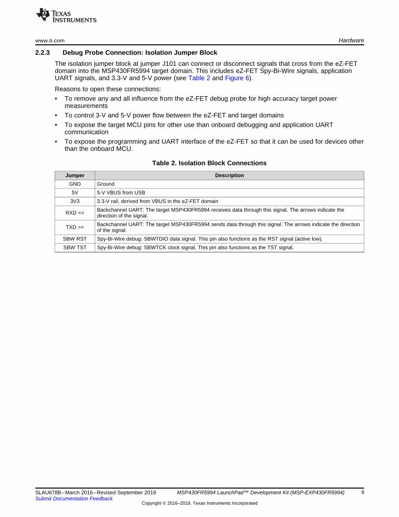
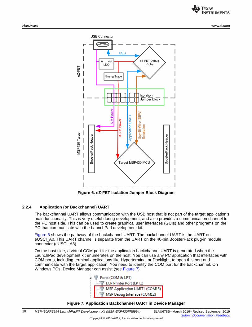
2.2.3 Debug Probe Connection: Isolation Jumper BlockThe isolation jumper block at jumper J101 can connect or disconnect signals that cross from the eZ-FETdomain into the MSP430FR5994 target domain. This includes eZ-FET Spy-Bi-Wire signals, applicationUART signals, and 3.3-V and 5-V power (see Table 2 and Figure 6).
Reasons to open these connections:• To remove any and all influence from the eZ-FET debug probe for high accuracy target power
measurements• To control 3-V and 5-V power flow between the eZ-FET and target domains• To expose the target MCU pins for other use than onboard debugging and application UART
communication• To expose the programming and UART interface of the eZ-FET so that it can be used for devices other
than the onboard MCU.
Table 2. Isolation Block Connections
Jumper DescriptionGND Ground5V 5-V VBUS from USB
3V3 3.3-V rail, derived from VBUS in the eZ-FET domain
RXD << Backchannel UART: The target MSP430FR5994 receives data through this signal. The arrows indicate thedirection of the signal.
TXD >> Backchannel UART: The target MSP430FR5994 sends data through this signal. The arrows indicate the directionof the signal.
SBW RST Spy-Bi-Wire debug: SBWTDIO data signal. This pin also functions as the RST signal (active low).SBW TST Spy-Bi-Wire debug: SBWTCK clock signal. This pin also functions as the TST signal.
eZ-FET Debug
Probe
Isolation Jumper Block
Sp
y-B
i-W
ire
(S
BW
)
Em
ula
tio
n
Ap
plic
atio
n U
AR
T
3.3
-V P
ow
er
5-V
Po
we
r
Target MSP430 MCU
eZ
-FE
TM
SP
43
0 T
arg
et
USB Connector
in out
LDO
Bo
oste
rPa
ck H
ea
de
r
Bo
oste
rPa
ck H
ea
de
r
USB
EnergyTrace
Hardware www.ti.com
10 SLAU678B–March 2016–Revised September 2019Submit Documentation Feedback
Copyright © 2016–2019, Texas Instruments Incorporated
MSP430FR5994 LaunchPad™ Development Kit (MSP‑EXP430FR5994)
Figure 6. eZ-FET Isolation Jumper Block Diagram
2.2.4 Application (or Backchannel) UARTThe backchannel UART allows communication with the USB host that is not part of the target application'smain functionality. This is very useful during development, and also provides a communication channel tothe PC host side. This can be used to create graphical user interfaces (GUIs) and other programs on thePC that communicate with the LaunchPad development kit.
Figure 6 shows the pathway of the backchannel UART. The backchannel UART is the UART oneUSCI_A0. This UART channel is separate from the UART on the 40-pin BoosterPack plug-in moduleconnector (eUSCI_A3).
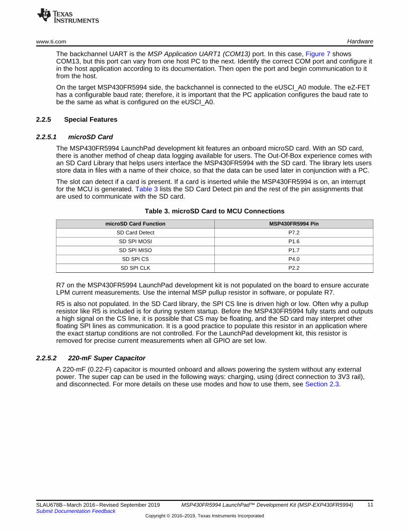
On the host side, a virtual COM port for the application backchannel UART is generated when theLaunchPad development kit enumerates on the host. You can use any PC application that interfaces withCOM ports, including terminal applications like Hyperterminal or Docklight, to open this port andcommunicate with the target application. You need to identify the COM port for the backchannel. OnWindows PCs, Device Manager can assist (see Figure 7).
Figure 7. Application Backchannel UART in Device Manager
www.ti.com Hardware
11SLAU678B–March 2016–Revised September 2019Submit Documentation Feedback
Copyright © 2016–2019, Texas Instruments Incorporated
MSP430FR5994 LaunchPad™ Development Kit (MSP‑EXP430FR5994)
The backchannel UART is the MSP Application UART1 (COM13) port. In this case, Figure 7 showsCOM13, but this port can vary from one host PC to the next. Identify the correct COM port and configure itin the host application according to its documentation. Then open the port and begin communication to itfrom the host.
On the target MSP430FR5994 side, the backchannel is connected to the eUSCI_A0 module. The eZ-FEThas a configurable baud rate; therefore, it is important that the PC application configures the baud rate tobe the same as what is configured on the eUSCI_A0.
2.2.5 Special Features
2.2.5.1 microSD CardThe MSP430FR5994 LaunchPad development kit features an onboard microSD card. With an SD card,there is another method of cheap data logging available for users. The Out-Of-Box experience comes withan SD Card Library that helps users interface the MSP430FR5994 with the SD card. The library lets usersstore data in files with a name of their choice, so that the data can be used later in conjunction with a PC.
The slot can detect if a card is present. If a card is inserted while the MSP430FR5994 is on, an interruptfor the MCU is generated. Table 3 lists the SD Card Detect pin and the rest of the pin assignments thatare used to communicate with the SD card.
Table 3. microSD Card to MCU Connections
microSD Card Function MSP430FR5994 PinSD Card Detect P7.2SD SPI MOSI P1.6SD SPI MISO P1.7
SD SPI CS P4.0SD SPI CLK P2.2
R7 on the MSP430FR5994 LaunchPad development kit is not populated on the board to ensure accurateLPM current measurements. Use the internal MSP pullup resistor in software, or populate R7.
R5 is also not populated. In the SD Card library, the SPI CS line is driven high or low. Often why a pullupresistor like R5 is included is for during system startup. Before the MSP430FR5994 fully starts and outputsa high signal on the CS line, it is possible that CS may be floating, and the SD card may interpret otherfloating SPI lines as communication. It is a good practice to populate this resistor in an application wherethe exact startup conditions are not controlled. For the LaunchPad development kit, this resistor isremoved for precise current measurements when all GPIO are set low.
2.2.5.2 220-mF Super CapacitorA 220-mF (0.22-F) capacitor is mounted onboard and allows powering the system without any externalpower. The super cap can be used in the following ways: charging, using (direct connection to 3V3 rail),and disconnected. For more details on these use modes and how to use them, see Section 2.3.
Hardware www.ti.com
12 SLAU678B–March 2016–Revised September 2019Submit Documentation Feedback
Copyright © 2016–2019, Texas Instruments Incorporated
MSP430FR5994 LaunchPad™ Development Kit (MSP‑EXP430FR5994)
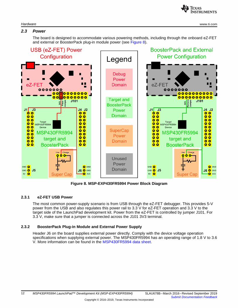
2.3 PowerThe board is designed to accommodate various powering methods, including through the onboard eZ-FETand external or BoosterPack plug-in module power (see Figure 8).
Figure 8. MSP-EXP430FR5994 Power Block Diagram
2.3.1 eZ-FET USB PowerThe most common power-supply scenario is from USB through the eZ-FET debugger. This provides 5-Vpower from the USB and also regulates this power rail to 3.3 V for eZ-FET operation and 3.3 V to thetarget side of the LaunchPad development kit. Power from the eZ-FET is controlled by jumper J101. For3.3 V, make sure that a jumper is connected across the J101 3V3 terminal.
2.3.2 BoosterPack Plug-in Module and External Power SupplyHeader J6 on the board supplies external power directly. Comply with the device voltage operationspecifications when supplying external power. The MSP430FR5994 has an operating range of 1.8 V to 3.6V. More information can be found in the MSP430FR5994 data sheet.
www.ti.com Hardware
13SLAU678B–March 2016–Revised September 2019Submit Documentation Feedback
Copyright © 2016–2019, Texas Instruments Incorporated
MSP430FR5994 LaunchPad™ Development Kit (MSP‑EXP430FR5994)
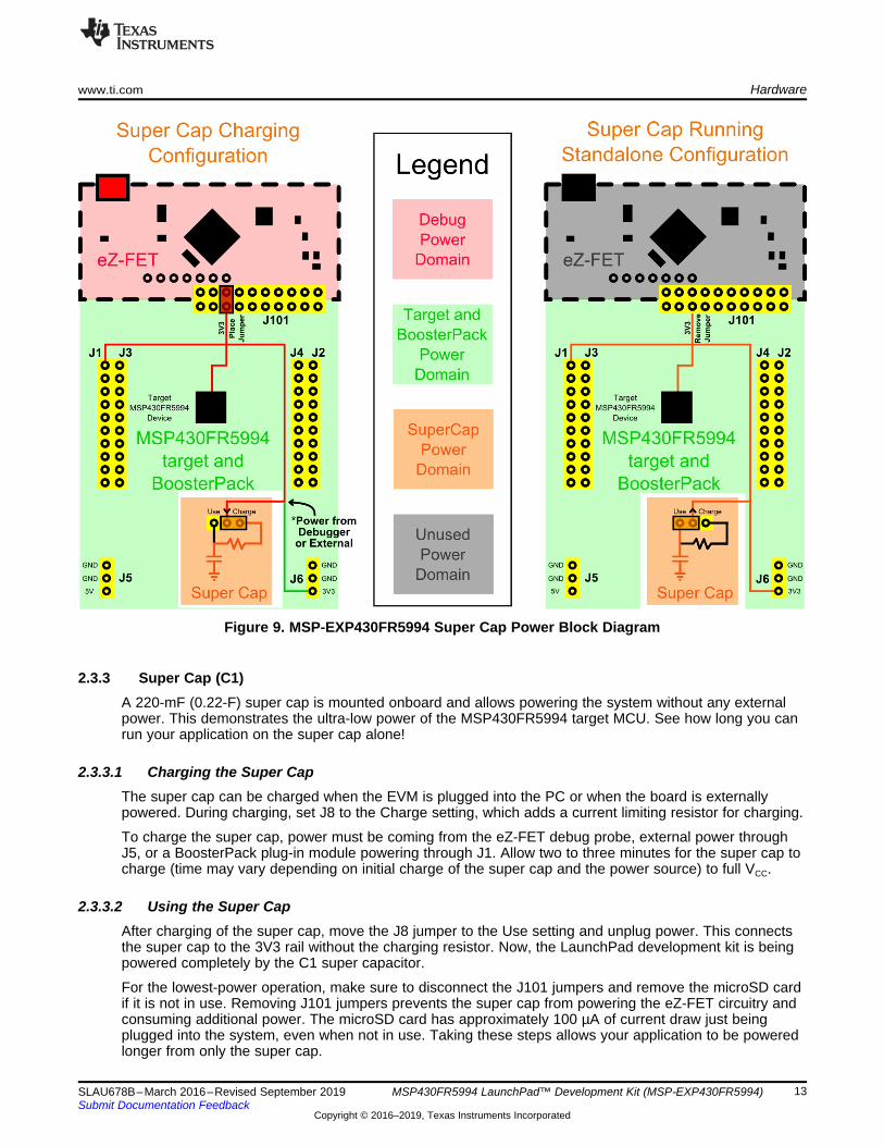
Figure 9. MSP-EXP430FR5994 Super Cap Power Block Diagram
2.3.3 Super Cap (C1)A 220-mF (0.22-F) super cap is mounted onboard and allows powering the system without any externalpower. This demonstrates the ultra-low power of the MSP430FR5994 target MCU. See how long you canrun your application on the super cap alone!
2.3.3.1 Charging the Super CapThe super cap can be charged when the EVM is plugged into the PC or when the board is externallypowered. During charging, set J8 to the Charge setting, which adds a current limiting resistor for charging.
To charge the super cap, power must be coming from the eZ-FET debug probe, external power throughJ5, or a BoosterPack plug-in module powering through J1. Allow two to three minutes for the super cap tocharge (time may vary depending on initial charge of the super cap and the power source) to full VCC.
2.3.3.2 Using the Super CapAfter charging of the super cap, move the J8 jumper to the Use setting and unplug power. This connectsthe super cap to the 3V3 rail without the charging resistor. Now, the LaunchPad development kit is beingpowered completely by the C1 super capacitor.
For the lowest-power operation, make sure to disconnect the J101 jumpers and remove the microSD cardif it is not in use. Removing J101 jumpers prevents the super cap from powering the eZ-FET circuitry andconsuming additional power. The microSD card has approximately 100 µA of current draw just beingplugged into the system, even when not in use. Taking these steps allows your application to be poweredlonger from only the super cap.

Hardware www.ti.com
14 SLAU678B–March 2016–Revised September 2019Submit Documentation Feedback
Copyright © 2016–2019, Texas Instruments Incorporated
MSP430FR5994 LaunchPad™ Development Kit (MSP‑EXP430FR5994)
2.3.3.3 Disabling the Super CapThe super cap can be completely decoupled from the board by removing the J8 jumper. Hang this jumperoff only one pin to prevent losing the jumper.
2.4 Measure MSP430 Current DrawTo measure the current draw of the MSP430FR5994 using a multimeter, use the 3V3 jumper on the J101jumper isolation block. The current measured includes the target device and any current drawn throughthe BoosterPack plug-in module headers.
To measure ultra-low power, follow these steps:1. Remove the 3V3 jumper in the J101 isolation block, and attach an ammeter across this jumper.2. Consider the effect that the backchannel UART and any circuitry attached to the MSP430FR5994 may
have on current draw. Consider disconnecting these at the isolation jumper block, or at least considertheir current sinking and sourcing capability in the final measurement.
3. Make sure there are no floating inputs or outputs (I/Os) on the MSP430FR5994. These causeunnecessary extra current draw. Every I/O should either be driven out or, if it is an input, should bepulled or driven to a high or low level.
4. Begin target execution.5. Measure the current. Keep in mind that if the current levels are fluctuating, it may be difficult to get a
stable measurement. It is easier to measure quiescent states.
Alternatively, EnergyTrace++ technology can be used to measure the same current, and see energyprofiles through integrated GUI in CCS and IAR. EnergyTrace allows you to compare various currentprofiles and better optimize the energy performance.
2.5 ClockingThe MSP-EXP430FR5994 provides external clocks in addition to the internal clocks in the device.• Q1: 32-kHz Epson crystal (FC-135R)• Q2: DNP high-frequency crystal footprint
The 32-kHz crystal allows for lower LPM3 sleep currents than do the other low-frequency clock sources.Therefore, the presence of the crystal allows the full range of low-power modes to be used.
The high-frequency crystal is not populated by default, but the footprint for a crystal is provided. Populatea high-frequency crystal for applications that need more precise high-frequency clock sources than theinternal DCO.
The internal clocks in the device default to the following configuration:• MCLK: DCO 1 MHz• SMCLK: DCO 1 MHz• ACLK: REFO 32.768 kHz
For more information about configuring internal clocks and using the external oscillators, see theMSP430FR58xx, MSP430FR59xx, and MSP430FR6xx Family User's Guide.
2.6 Using the eZ-FET Debug Probe With a Different TargetThe eZ-FET debug probe on the LaunchPad development kit can interface to most MSP430 derivativedevices, not just the onboard MSP430FR5994 target device.
To do this, disconnect every jumper in the isolation jumper block. This is necessary, because the debugprobe cannot connect to more than one target at a time over the Spy-Bi-Wire (SBW) connection.
Next, make sure the target board has proper connections for SBW. To be compatible with SBW, thecapacitor on RST/SBWTDIO cannot be greater than 2.2 nF. The documentation for designing MSP430JTAG interface circuitry is the MSP430 Hardware Tools User's Guide.
Finally, wire together these signals from the debug probe side of the isolation jumper block to the targethardware:
www.ti.com Hardware
15SLAU678B–March 2016–Revised September 2019Submit Documentation Feedback
Copyright © 2016–2019, Texas Instruments Incorporated
MSP430FR5994 LaunchPad™ Development Kit (MSP‑EXP430FR5994)
• 5 V (if 5 V is needed)• 3.3 V• GND• SBWTDIO• SBWTCK• TXD (if the UART backchannel is to be used)• RXD (if the UART backchannel is to be used)
This wiring can be done either with jumper wires or by designing the board with a connector that plugs intothe isolation jumper block.
2.7 BoosterPack Plug-in Module PinoutThis LaunchPad development kit complies with the 40-pin LaunchPad development kit pinout standard.This standard was created to aid compatibility between LaunchPad development kits and BoosterPackplug-in modules across the TI ecosystem.
The 40-pin standard is compatible with the 20-pin standard that is used by other LaunchPad developmentkit like the MSP-EXP430FR4133. This allows some subset of functionality of 40-pin BoosterPack plug-inmodules to be used with 20-pin LaunchPad development kits.
While most BoosterPack plug-in modules are compliant with the standard, some are not. The MSP-EXP430FR5994 LaunchPad development kit is compatible with all 40-pin BoosterPack plug-in module thatcomply with the standard. If the reseller or owner of the BoosterPack plug-in module does not explicitlyindicate compatibility with the MSP-EXP430FR5994 LaunchPad development kit, compare the schematicof the candidate BoosterPack plug-in module with the LaunchPad development kit to ensure compatibility.Keep in mind that sometimes conflicts can be resolved by changing the MSP430FR5994 MCU pinfunction configuration in software.
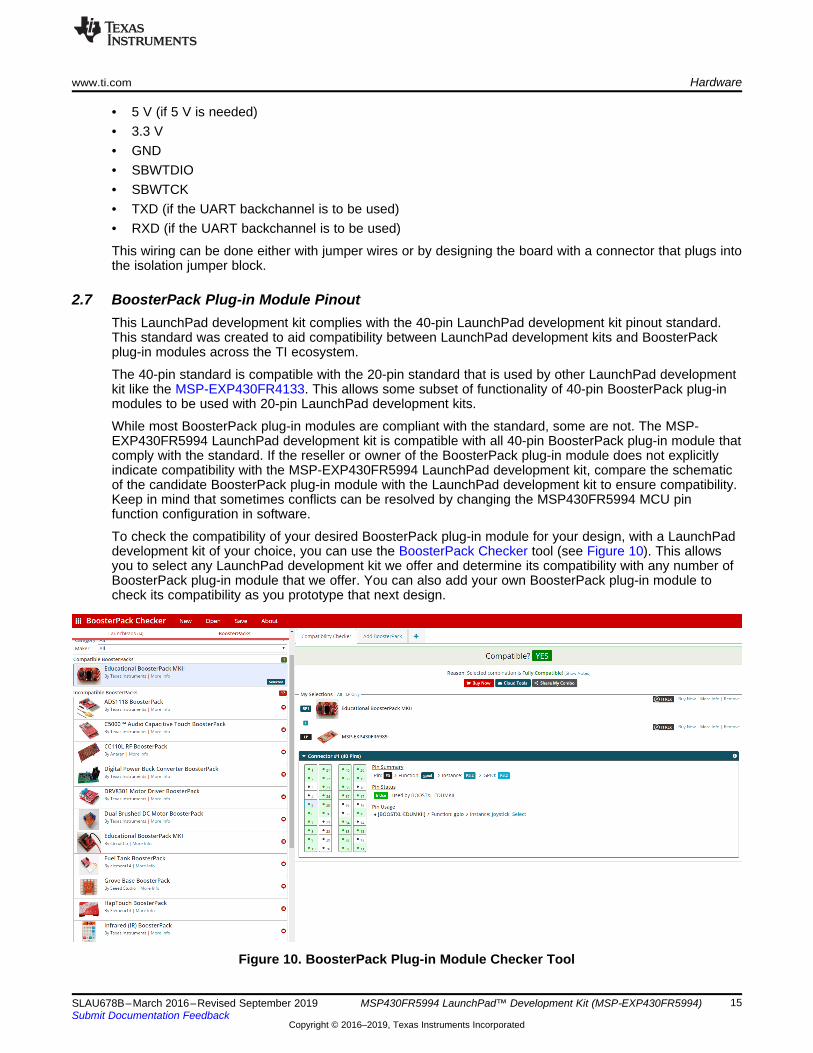
To check the compatibility of your desired BoosterPack plug-in module for your design, with a LaunchPaddevelopment kit of your choice, you can use the BoosterPack Checker tool (see Figure 10). This allowsyou to select any LaunchPad development kit we offer and determine its compatibility with any number ofBoosterPack plug-in module that we offer. You can also add your own BoosterPack plug-in module tocheck its compatibility as you prototype that next design.
Figure 10. BoosterPack Plug-in Module Checker Tool
Hardware www.ti.com
16 SLAU678B–March 2016–Revised September 2019Submit Documentation Feedback
Copyright © 2016–2019, Texas Instruments Incorporated
MSP430FR5994 LaunchPad™ Development Kit (MSP‑EXP430FR5994)
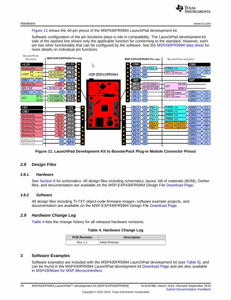
Figure 11 shows the 40-pin pinout of the MSP430FR5994 LaunchPad development kit.
Software configuration of the pin functions plays a role in compatibility. The LaunchPad development kitside of the dashed line shows only the applicable function for conforming to the standard. However, eachpin has other functionality that can be configured by the software. See the MSP430FR5994 data sheet formore details on individual pin functions.
Figure 11. LaunchPad Development Kit to BoosterPack Plug-in Module Connector Pinout
2.8 Design Files
2.8.1 HardwareSee Section 6 for schematics. All design files including schematics, layout, bill of materials (BOM), Gerberfiles, and documentation are available on the MSP-EXP430FR5994 Design File Download Page.
2.8.2 SoftwareAll design files including TI-TXT object-code firmware images, software example projects, anddocumentation are available on the MSP-EXP430FR5994 Design File Download Page.
2.9 Hardware Change LogTable 4 lists the change history for all released hardware revisions.
Table 4. Hardware Change Log
PCB Revision DescriptionRev 1.1 Initial Release
3 Software ExamplesSoftware examples are included with the MSP430FR5994 LaunchPad development kit (see Table 5), andcan be found in the MSP430FR5994 LaunchPad development kit Download Page and are also availablein MSP430Ware for MSP Microcontrollers.
www.ti.com Software Examples
17SLAU678B–March 2016–Revised September 2019Submit Documentation Feedback
Copyright © 2016–2019, Texas Instruments Incorporated
MSP430FR5994 LaunchPad™ Development Kit (MSP‑EXP430FR5994)
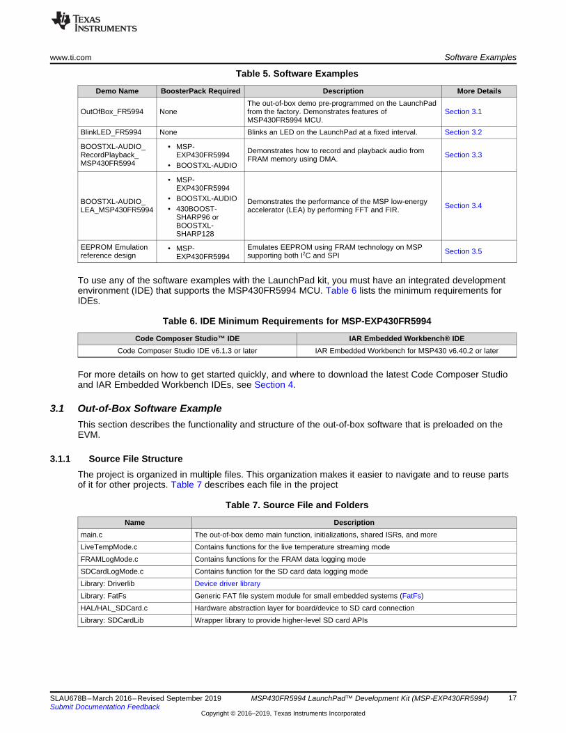
Table 5. Software Examples
Demo Name BoosterPack Required Description More Details
OutOfBox_FR5994 NoneThe out-of-box demo pre-programmed on the LaunchPadfrom the factory. Demonstrates features ofMSP430FR5994 MCU.
Section 3.1
BlinkLED_FR5994 None Blinks an LED on the LaunchPad at a fixed interval. Section 3.2
BOOSTXL-AUDIO_RecordPlayback_MSP430FR5994
• MSP-EXP430FR5994
• BOOSTXL-AUDIO
Demonstrates how to record and playback audio fromFRAM memory using DMA. Section 3.3
BOOSTXL-AUDIO_LEA_MSP430FR5994
• MSP-EXP430FR5994
• BOOSTXL-AUDIO• 430BOOST-
SHARP96 orBOOSTXL-SHARP128
Demonstrates the performance of the MSP low-energyaccelerator (LEA) by performing FFT and FIR. Section 3.4
EEPROM Emulationreference design
• MSP-EXP430FR5994
Emulates EEPROM using FRAM technology on MSPsupporting both I2C and SPI Section 3.5
To use any of the software examples with the LaunchPad kit, you must have an integrated developmentenvironment (IDE) that supports the MSP430FR5994 MCU. Table 6 lists the minimum requirements forIDEs.
Table 6. IDE Minimum Requirements for MSP-EXP430FR5994
Code Composer Studio™ IDE IAR Embedded Workbench® IDECode Composer Studio IDE v6.1.3 or later IAR Embedded Workbench for MSP430 v6.40.2 or later
For more details on how to get started quickly, and where to download the latest Code Composer Studioand IAR Embedded Workbench IDEs, see Section 4.
3.1 Out-of-Box Software ExampleThis section describes the functionality and structure of the out-of-box software that is preloaded on theEVM.
3.1.1 Source File StructureThe project is organized in multiple files. This organization makes it easier to navigate and to reuse partsof it for other projects. Table 7 describes each file in the project
Table 7. Source File and Folders
Name Descriptionmain.c The out-of-box demo main function, initializations, shared ISRs, and moreLiveTempMode.c Contains functions for the live temperature streaming modeFRAMLogMode.c Contains functions for the FRAM data logging modeSDCardLogMode.c Contains function for the SD card data logging modeLibrary: Driverlib Device driver libraryLibrary: FatFs Generic FAT file system module for small embedded systems (FatFs)HAL/HAL_SDCard.c Hardware abstraction layer for board/device to SD card connectionLibrary: SDCardLib Wrapper library to provide higher-level SD card APIs
Software Examples www.ti.com
18 SLAU678B–March 2016–Revised September 2019Submit Documentation Feedback
Copyright © 2016–2019, Texas Instruments Incorporated
MSP430FR5994 LaunchPad™ Development Kit (MSP‑EXP430FR5994)
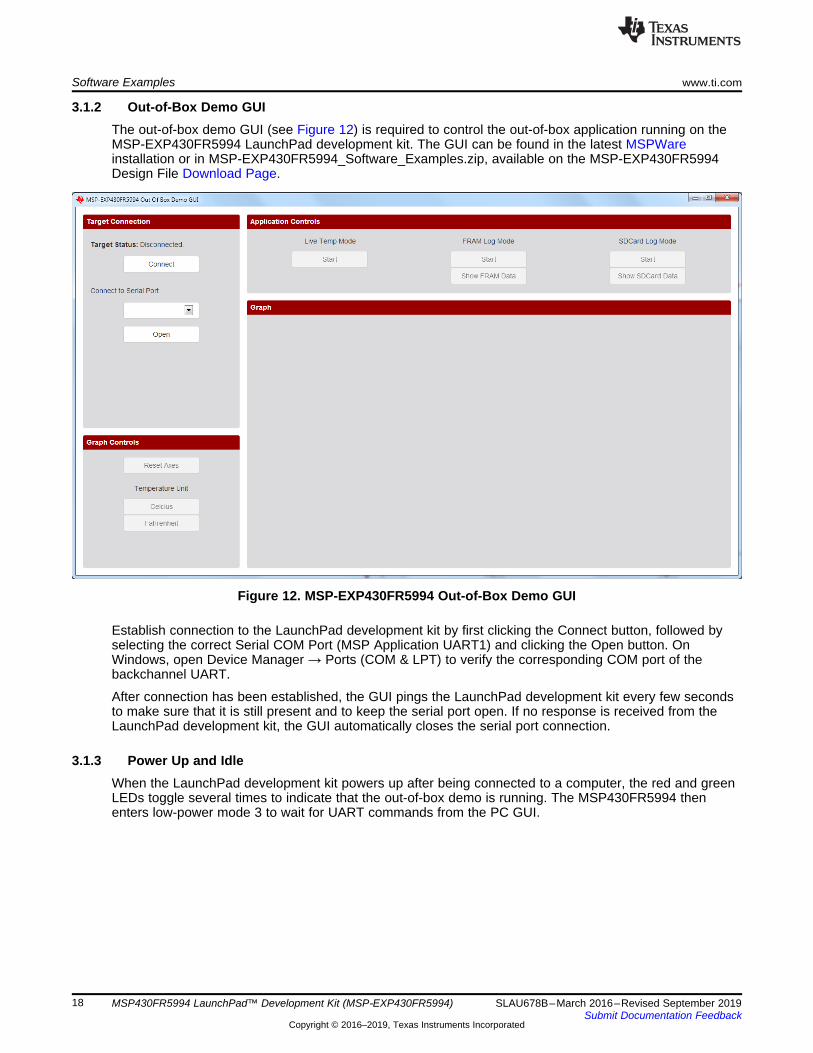
3.1.2 Out-of-Box Demo GUIThe out-of-box demo GUI (see Figure 12) is required to control the out-of-box application running on theMSP-EXP430FR5994 LaunchPad development kit. The GUI can be found in the latest MSPWareinstallation or in MSP-EXP430FR5994_Software_Examples.zip, available on the MSP-EXP430FR5994Design File Download Page.
Figure 12. MSP-EXP430FR5994 Out-of-Box Demo GUI
Establish connection to the LaunchPad development kit by first clicking the Connect button, followed byselecting the correct Serial COM Port (MSP Application UART1) and clicking the Open button. OnWindows, open Device Manager → Ports (COM & LPT) to verify the corresponding COM port of thebackchannel UART.
After connection has been established, the GUI pings the LaunchPad development kit every few secondsto make sure that it is still present and to keep the serial port open. If no response is received from theLaunchPad development kit, the GUI automatically closes the serial port connection.
3.1.3 Power Up and IdleWhen the LaunchPad development kit powers up after being connected to a computer, the red and greenLEDs toggle several times to indicate that the out-of-box demo is running. The MSP430FR5994 thenenters low-power mode 3 to wait for UART commands from the PC GUI.
www.ti.com Software Examples
19SLAU678B–March 2016–Revised September 2019Submit Documentation Feedback
Copyright © 2016–2019, Texas Instruments Incorporated
MSP430FR5994 LaunchPad™ Development Kit (MSP‑EXP430FR5994)
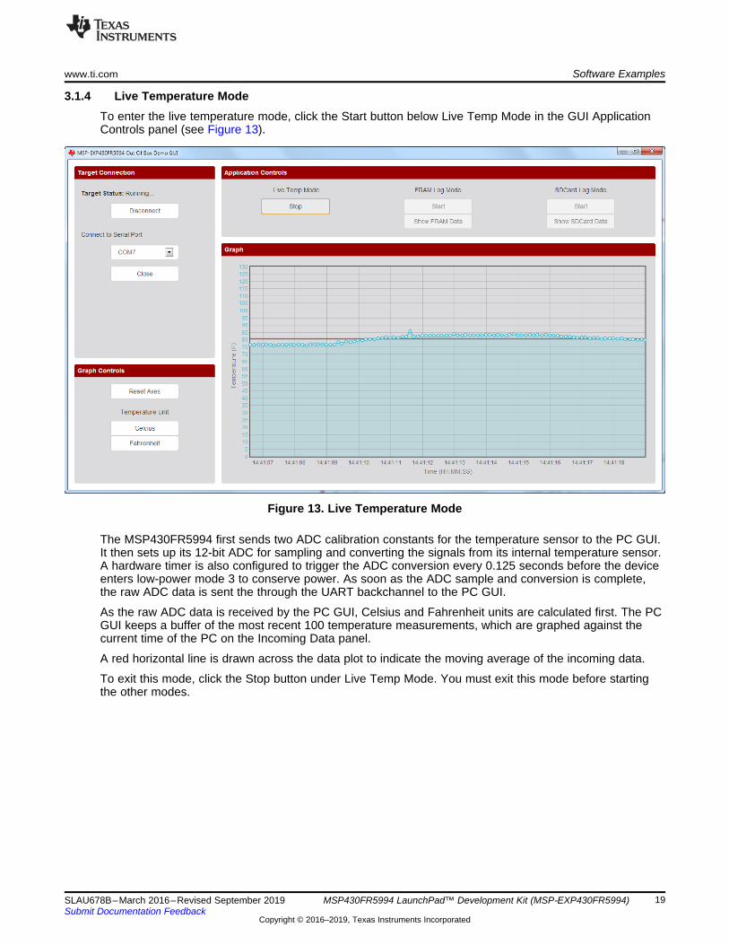
3.1.4 Live Temperature ModeTo enter the live temperature mode, click the Start button below Live Temp Mode in the GUI ApplicationControls panel (see Figure 13).
Figure 13. Live Temperature Mode
The MSP430FR5994 first sends two ADC calibration constants for the temperature sensor to the PC GUI.It then sets up its 12-bit ADC for sampling and converting the signals from its internal temperature sensor.A hardware timer is also configured to trigger the ADC conversion every 0.125 seconds before the deviceenters low-power mode 3 to conserve power. As soon as the ADC sample and conversion is complete,the raw ADC data is sent the through the UART backchannel to the PC GUI.
As the raw ADC data is received by the PC GUI, Celsius and Fahrenheit units are calculated first. The PCGUI keeps a buffer of the most recent 100 temperature measurements, which are graphed against thecurrent time of the PC on the Incoming Data panel.
A red horizontal line is drawn across the data plot to indicate the moving average of the incoming data.
To exit this mode, click the Stop button under Live Temp Mode. You must exit this mode before startingthe other modes.
Software Examples www.ti.com
20 SLAU678B–March 2016–Revised September 2019Submit Documentation Feedback
Copyright © 2016–2019, Texas Instruments Incorporated
MSP430FR5994 LaunchPad™ Development Kit (MSP‑EXP430FR5994)
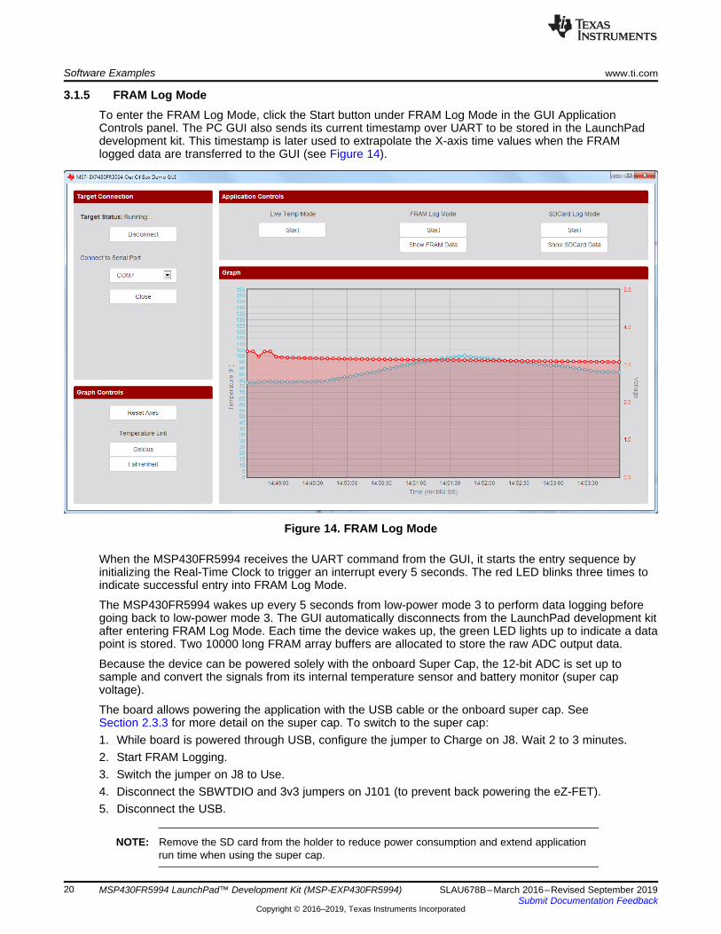
3.1.5 FRAM Log ModeTo enter the FRAM Log Mode, click the Start button under FRAM Log Mode in the GUI ApplicationControls panel. The PC GUI also sends its current timestamp over UART to be stored in the LaunchPaddevelopment kit. This timestamp is later used to extrapolate the X-axis time values when the FRAMlogged data are transferred to the GUI (see Figure 14).
Figure 14. FRAM Log Mode
When the MSP430FR5994 receives the UART command from the GUI, it starts the entry sequence byinitializing the Real-Time Clock to trigger an interrupt every 5 seconds. The red LED blinks three times toindicate successful entry into FRAM Log Mode.
The MSP430FR5994 wakes up every 5 seconds from low-power mode 3 to perform data logging beforegoing back to low-power mode 3. The GUI automatically disconnects from the LaunchPad development kitafter entering FRAM Log Mode. Each time the device wakes up, the green LED lights up to indicate a datapoint is stored. Two 10000 long FRAM array buffers are allocated to store the raw ADC output data.
Because the device can be powered solely with the onboard Super Cap, the 12-bit ADC is set up tosample and convert the signals from its internal temperature sensor and battery monitor (super capvoltage).
The board allows powering the application with the USB cable or the onboard super cap. SeeSection 2.3.3 for more detail on the super cap. To switch to the super cap:1. While board is powered through USB, configure the jumper to Charge on J8. Wait 2 to 3 minutes.2. Start FRAM Logging.3. Switch the jumper on J8 to Use.4. Disconnect the SBWTDIO and 3v3 jumpers on J101 (to prevent back powering the eZ-FET).5. Disconnect the USB.
NOTE: Remove the SD card from the holder to reduce power consumption and extend applicationrun time when using the super cap.
www.ti.com Software Examples
21SLAU678B–March 2016–Revised September 2019Submit Documentation Feedback
Copyright © 2016–2019, Texas Instruments Incorporated
MSP430FR5994 LaunchPad™ Development Kit (MSP‑EXP430FR5994)
To exit the FRAM Log Mode, press the S2 (right) push button on the LaunchPad development kit. The redLED turns on briefly to indicate successful exit and return to the Power up and Idle state. Reattach thejumpers to the default positions and connect USB. Re-open the serial port to the LaunchPad developmentkit in the GUI. Click the Transfer FRAM Data button to transmit the logged temperature and voltage datafrom the device FRAM to the PC.
3.1.6 SD Card Log ModeThe SD card mode works similarly to the FRAM Log Mode, except that the temperature and voltage dataare stored into .txt files on the SD card. Each time the SD card log mode is started, a new LOG_#.TXT (#increments for the next file) is created under /root/DATA_LOG/.
Enter and exit SD card log mode the same way that you enter and exit FRAM log mode. Click Show SDCard Data to transfer the data from the most recently created LOG_#.TXT to the PC.
NOTE: The super cap cannot power the SD card log mode for long periods of time, because the SDcard consumes significantly more power.
3.2 Blink LED ExampleThis simple software example demonstrates how to software toggle a GPIO to blink an LED on theLaunchPad kit.
3.2.1 Source File StructureThe project is split into multiple files (see Table 8). This makes it easier to navigate and reuse parts of itfor other projects.
Table 8. Source File and Folders
Name Descriptionmain.c The Blink LED main functionLibrary: Driverlib Device driver library
The main code uses the MSP430 Driver Library to halt the watchdog timer and to configure/toggle theP1.0 GPIO pin connected to the LED inside a software loop.
Software Examples www.ti.com
22 SLAU678B–March 2016–Revised September 2019Submit Documentation Feedback
Copyright © 2016–2019, Texas Instruments Incorporated
MSP430FR5994 LaunchPad™ Development Kit (MSP‑EXP430FR5994)
3.3 BOOSTXL-AUDIO Audio Record and Playback ExampleThis section describes the functionality and structure of the BOOSTXL-AUDIO_RecordPlayback_MSP430FR5994 demo that is included in the MSP-EXP430FR5994 SoftwareExamples download, or that is more easily accessible through MSPWare (see Section 4.3).
3.3.1 Source File StructureThe project is split into multiple files (see Table 9). This makes it easier to navigate and reuse parts of itfor other projects.
Table 9. Source File and Folders
Name Descriptionmain.c The demo's clock, GPIO, DAC and interrupt configurations.application/application.c Main application loop and interrupt service routinesapplication/audio_collect.c Setup, start, stop and shutdown audio collect functionsapplication/audio_playback.c Setup, start and stop playback functions and interrupt service routinesapplication/dac8311.c Operating modes/functions of the onboard SPI DACapplication/global.h Global variables definitionsLibrary: driverlib Device driver library
3.3.2 OperationThis demo uses the built-in ADC12 on the MSP430FR5994 MCU to sample from the output of the analogmicrophone on the Audio Signal Processing BoosterPack plug-in module. Using direct memory access(DMA), the 12-bit microphone data is stored and retrieved from FRAM memory. During playback, themicrophone data is sent through SPI to the onboard DAC to drive the audio output of the onboard speakeror headphones.
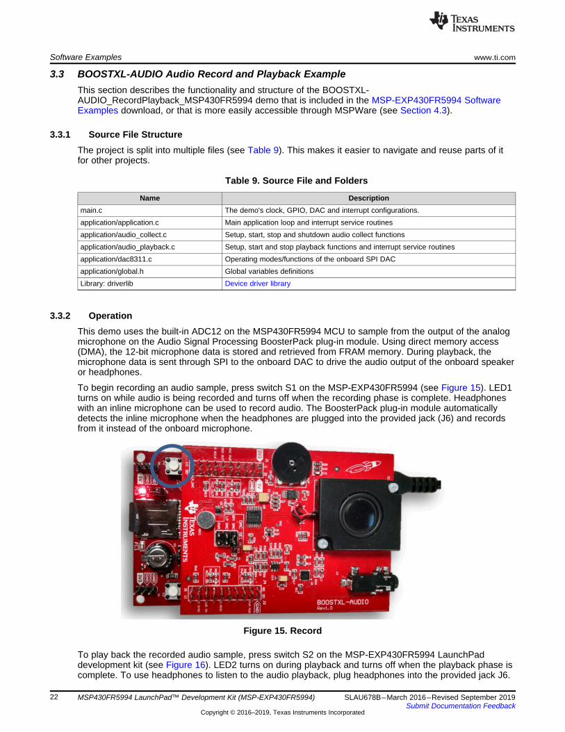
To begin recording an audio sample, press switch S1 on the MSP-EXP430FR5994 (see Figure 15). LED1turns on while audio is being recorded and turns off when the recording phase is complete. Headphoneswith an inline microphone can be used to record audio. The BoosterPack plug-in module automaticallydetects the inline microphone when the headphones are plugged into the provided jack (J6) and recordsfrom it instead of the onboard microphone.
Figure 15. Record
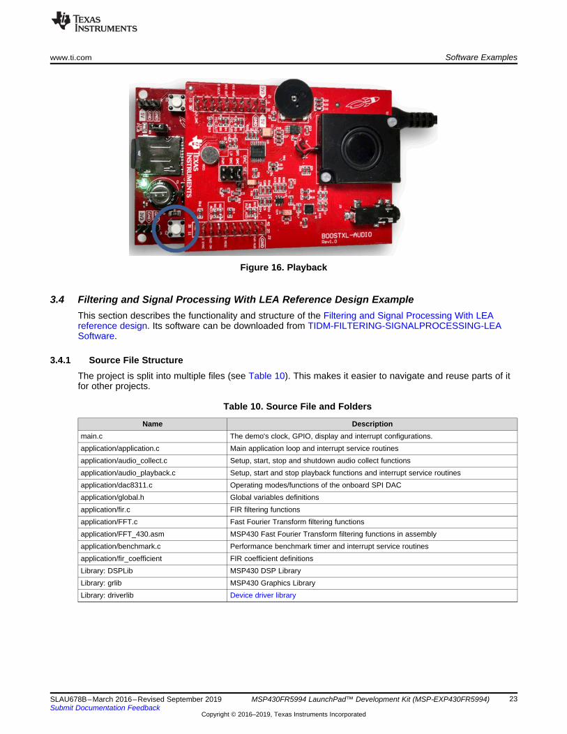
To play back the recorded audio sample, press switch S2 on the MSP-EXP430FR5994 LaunchPaddevelopment kit (see Figure 16). LED2 turns on during playback and turns off when the playback phase iscomplete. To use headphones to listen to the audio playback, plug headphones into the provided jack J6.
www.ti.com Software Examples
23SLAU678B–March 2016–Revised September 2019Submit Documentation Feedback
Copyright © 2016–2019, Texas Instruments Incorporated
MSP430FR5994 LaunchPad™ Development Kit (MSP‑EXP430FR5994)
Figure 16. Playback
3.4 Filtering and Signal Processing With LEA Reference Design ExampleThis section describes the functionality and structure of the Filtering and Signal Processing With LEAreference design. Its software can be downloaded from TIDM-FILTERING-SIGNALPROCESSING-LEASoftware.
3.4.1 Source File StructureThe project is split into multiple files (see Table 10). This makes it easier to navigate and reuse parts of itfor other projects.
Table 10. Source File and Folders
Name Descriptionmain.c The demo's clock, GPIO, display and interrupt configurations.application/application.c Main application loop and interrupt service routinesapplication/audio_collect.c Setup, start, stop and shutdown audio collect functionsapplication/audio_playback.c Setup, start and stop playback functions and interrupt service routinesapplication/dac8311.c Operating modes/functions of the onboard SPI DACapplication/global.h Global variables definitionsapplication/fir.c FIR filtering functionsapplication/FFT.c Fast Fourier Transform filtering functionsapplication/FFT_430.asm MSP430 Fast Fourier Transform filtering functions in assemblyapplication/benchmark.c Performance benchmark timer and interrupt service routinesapplication/fir_coefficient FIR coefficient definitionsLibrary: DSPLib MSP430 DSP LibraryLibrary: grlib MSP430 Graphics LibraryLibrary: driverlib Device driver library
Software Examples www.ti.com
24 SLAU678B–March 2016–Revised September 2019Submit Documentation Feedback
Copyright © 2016–2019, Texas Instruments Incorporated
MSP430FR5994 LaunchPad™ Development Kit (MSP‑EXP430FR5994)
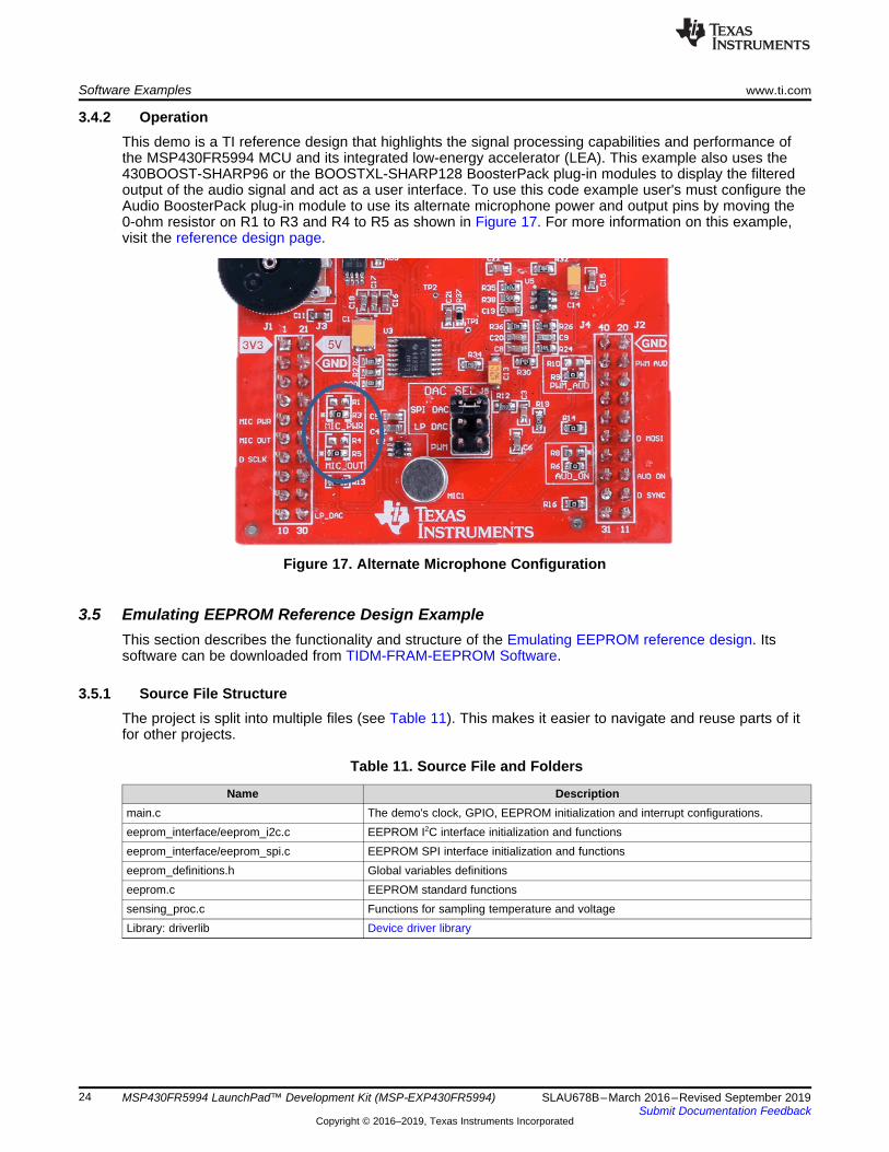
3.4.2 OperationThis demo is a TI reference design that highlights the signal processing capabilities and performance ofthe MSP430FR5994 MCU and its integrated low-energy accelerator (LEA). This example also uses the430BOOST-SHARP96 or the BOOSTXL-SHARP128 BoosterPack plug-in modules to display the filteredoutput of the audio signal and act as a user interface. To use this code example user's must configure theAudio BoosterPack plug-in module to use its alternate microphone power and output pins by moving the0-ohm resistor on R1 to R3 and R4 to R5 as shown in Figure 17. For more information on this example,visit the reference design page.
Figure 17. Alternate Microphone Configuration
3.5 Emulating EEPROM Reference Design ExampleThis section describes the functionality and structure of the Emulating EEPROM reference design. Itssoftware can be downloaded from TIDM-FRAM-EEPROM Software.
3.5.1 Source File StructureThe project is split into multiple files (see Table 11). This makes it easier to navigate and reuse parts of itfor other projects.
Table 11. Source File and Folders
Name Descriptionmain.c The demo's clock, GPIO, EEPROM initialization and interrupt configurations.eeprom_interface/eeprom_i2c.c EEPROM I2C interface initialization and functionseeprom_interface/eeprom_spi.c EEPROM SPI interface initialization and functionseeprom_definitions.h Global variables definitionseeprom.c EEPROM standard functionssensing_proc.c Functions for sampling temperature and voltageLibrary: driverlib Device driver library
FRAM EEPROM
Host Processor
MSP430FR5994
TIDM-FRAM-EEPROM
VCC Measure
and Sensing
WP
SCL
SDA
VCC
FRAM EEPROM
Host Processor
MSP430FR5994
TIDM-FRAM-EEPROM
VCC Measure/
SensingCS
WP
SCLK
MOSI
MISO
www.ti.com Resources
25SLAU678B–March 2016–Revised September 2019Submit Documentation Feedback
Copyright © 2016–2019, Texas Instruments Incorporated
MSP430FR5994 LaunchPad™ Development Kit (MSP‑EXP430FR5994)
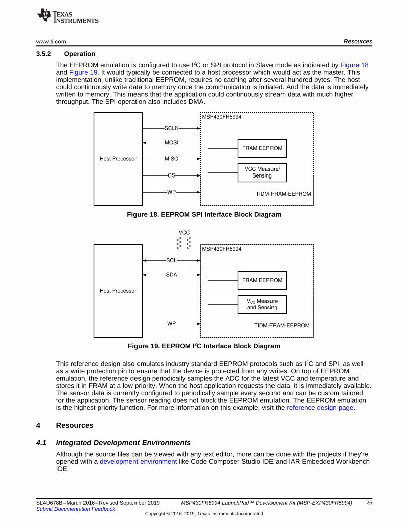
3.5.2 OperationThe EEPROM emulation is configured to use I2C or SPI protocol in Slave mode as indicated by Figure 18and Figure 19. It would typically be connected to a host processor which would act as the master. Thisimplementation, unlike traditional EEPROM, requires no caching after several hundred bytes. The hostcould continuously write data to memory once the communication is initiated. And the data is immediatelywritten to memory. This means that the application could continuously stream data with much higherthroughput. The SPI operation also includes DMA.
Figure 18. EEPROM SPI Interface Block Diagram
Figure 19. EEPROM I2C Interface Block Diagram
This reference design also emulates industry standard EEPROM protocols such as I2C and SPI, as wellas a write protection pin to ensure that the device is protected from any writes. On top of EEPROMemulation, the reference design periodically samples the ADC for the latest VCC and temperature andstores it in FRAM at a low priority. When the host application requests the data, it is immediately available.The sensor data is currently configured to periodically sample every second and can be custom tailoredfor the application. The sensor reading does not block the EEPROM emulation. The EEPROM emulationis the highest priority function. For more information on this example, visit the reference design page.
4 Resources
4.1 Integrated Development EnvironmentsAlthough the source files can be viewed with any text editor, more can be done with the projects if they'reopened with a development environment like Code Composer Studio IDE and IAR Embedded WorkbenchIDE.
Resources www.ti.com
26 SLAU678B–March 2016–Revised September 2019Submit Documentation Feedback
Copyright © 2016–2019, Texas Instruments Incorporated
MSP430FR5994 LaunchPad™ Development Kit (MSP‑EXP430FR5994)
4.1.1 TI Cloud Development ToolsTI's Cloud-based software development tools provide instant access to MSPWare content and a web-based IDE.
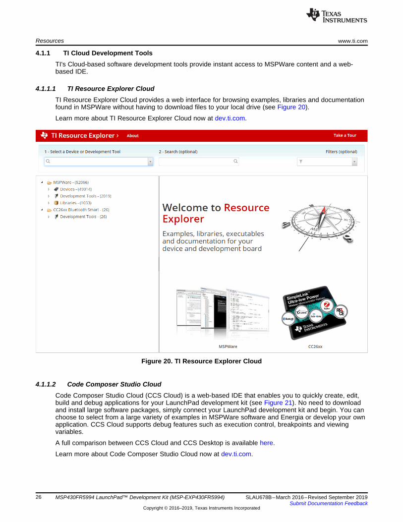
4.1.1.1 TI Resource Explorer CloudTI Resource Explorer Cloud provides a web interface for browsing examples, libraries and documentationfound in MSPWare without having to download files to your local drive (see Figure 20).
Learn more about TI Resource Explorer Cloud now at dev.ti.com.
Figure 20. TI Resource Explorer Cloud
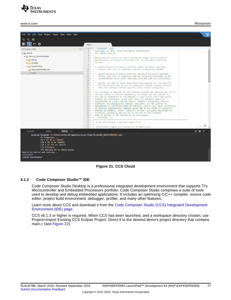
4.1.1.2 Code Composer Studio CloudCode Composer Studio Cloud (CCS Cloud) is a web-based IDE that enables you to quickly create, edit,build and debug applications for your LaunchPad development kit (see Figure 21). No need to downloadand install large software packages, simply connect your LaunchPad development kit and begin. You canchoose to select from a large variety of examples in MSPWare software and Energia or develop your ownapplication. CCS Cloud supports debug features such as execution control, breakpoints and viewingvariables.
A full comparison between CCS Cloud and CCS Desktop is available here.
Learn more about Code Composer Studio Cloud now at dev.ti.com.
www.ti.com Resources
27SLAU678B–March 2016–Revised September 2019Submit Documentation Feedback
Copyright © 2016–2019, Texas Instruments Incorporated
MSP430FR5994 LaunchPad™ Development Kit (MSP‑EXP430FR5994)
Figure 21. CCS Cloud
4.1.2 Code Composer Studio™ IDECode Composer Studio Desktop is a professional integrated development environment that supports TI'sMicrocontroller and Embedded Processors portfolio. Code Composer Studio comprises a suite of toolsused to develop and debug embedded applications. It includes an optimizing C/C++ compiler, source codeeditor, project build environment, debugger, profiler, and many other features.
Learn more about CCS and download it from the Code Composer Studio (CCS) Integrated DevelopmentEnvironment (IDE) page.
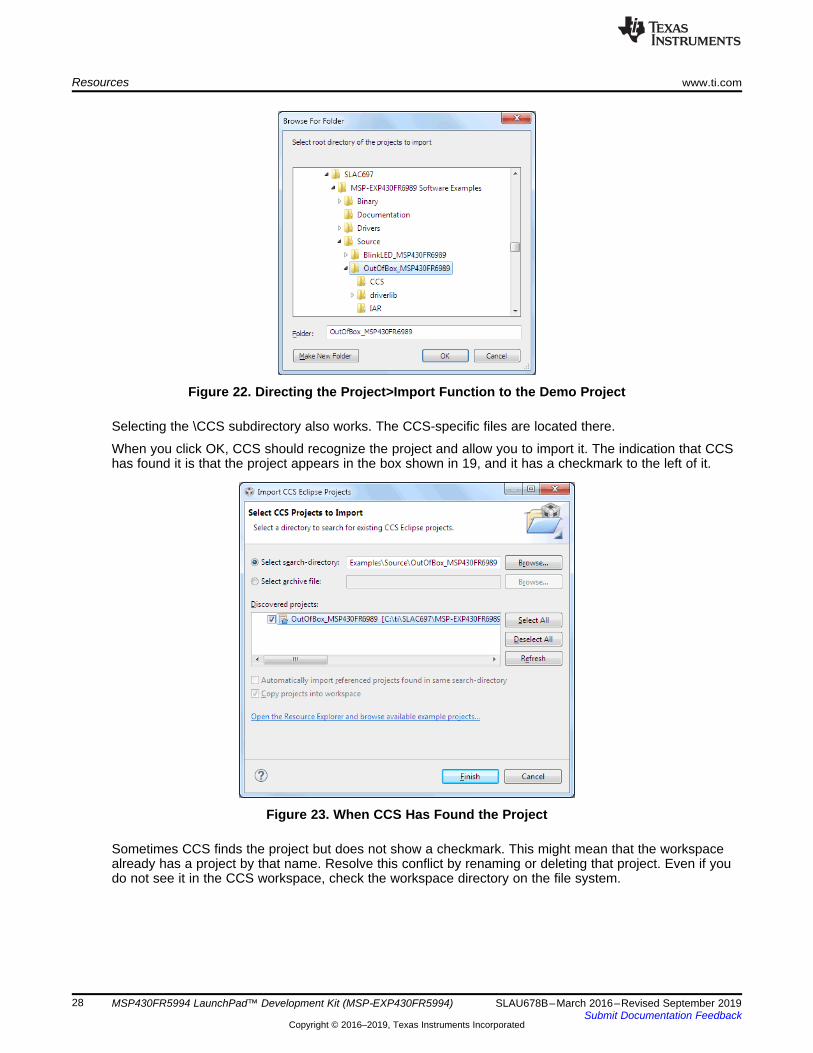
CCS v6.1.3 or higher is required. When CCS has been launched, and a workspace directory chosen, useProject>Import Existing CCS Eclipse Project. Direct it to the desired demo's project directory that containsmain.c (see Figure 22).
Resources www.ti.com
28 SLAU678B–March 2016–Revised September 2019Submit Documentation Feedback
Copyright © 2016–2019, Texas Instruments Incorporated
MSP430FR5994 LaunchPad™ Development Kit (MSP‑EXP430FR5994)
Figure 22. Directing the Project>Import Function to the Demo Project
Selecting the \CCS subdirectory also works. The CCS-specific files are located there.
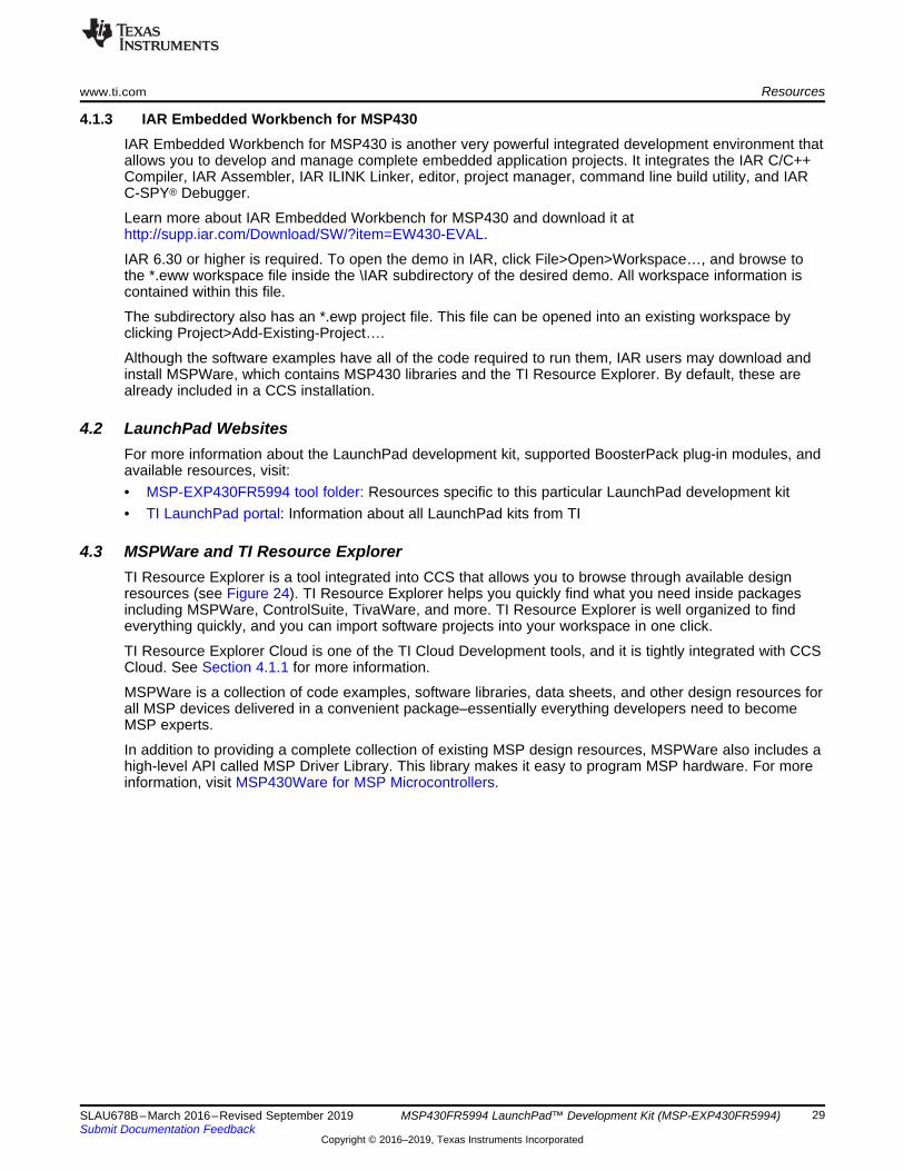
When you click OK, CCS should recognize the project and allow you to import it. The indication that CCShas found it is that the project appears in the box shown in 19, and it has a checkmark to the left of it.
Figure 23. When CCS Has Found the Project
Sometimes CCS finds the project but does not show a checkmark. This might mean that the workspacealready has a project by that name. Resolve this conflict by renaming or deleting that project. Even if youdo not see it in the CCS workspace, check the workspace directory on the file system.
www.ti.com Resources
29SLAU678B–March 2016–Revised September 2019Submit Documentation Feedback
Copyright © 2016–2019, Texas Instruments Incorporated
MSP430FR5994 LaunchPad™ Development Kit (MSP‑EXP430FR5994)
4.1.3 IAR Embedded Workbench for MSP430IAR Embedded Workbench for MSP430 is another very powerful integrated development environment thatallows you to develop and manage complete embedded application projects. It integrates the IAR C/C++Compiler, IAR Assembler, IAR ILINK Linker, editor, project manager, command line build utility, and IARC-SPY® Debugger.
Learn more about IAR Embedded Workbench for MSP430 and download it athttp://supp.iar.com/Download/SW/?item=EW430-EVAL.
IAR 6.30 or higher is required. To open the demo in IAR, click File>Open>Workspace…, and browse tothe *.eww workspace file inside the \IAR subdirectory of the desired demo. All workspace information iscontained within this file.
The subdirectory also has an *.ewp project file. This file can be opened into an existing workspace byclicking Project>Add-Existing-Project….
Although the software examples have all of the code required to run them, IAR users may download andinstall MSPWare, which contains MSP430 libraries and the TI Resource Explorer. By default, these arealready included in a CCS installation.
4.2 LaunchPad WebsitesFor more information about the LaunchPad development kit, supported BoosterPack plug-in modules, andavailable resources, visit:• MSP-EXP430FR5994 tool folder: Resources specific to this particular LaunchPad development kit• TI LaunchPad portal: Information about all LaunchPad kits from TI
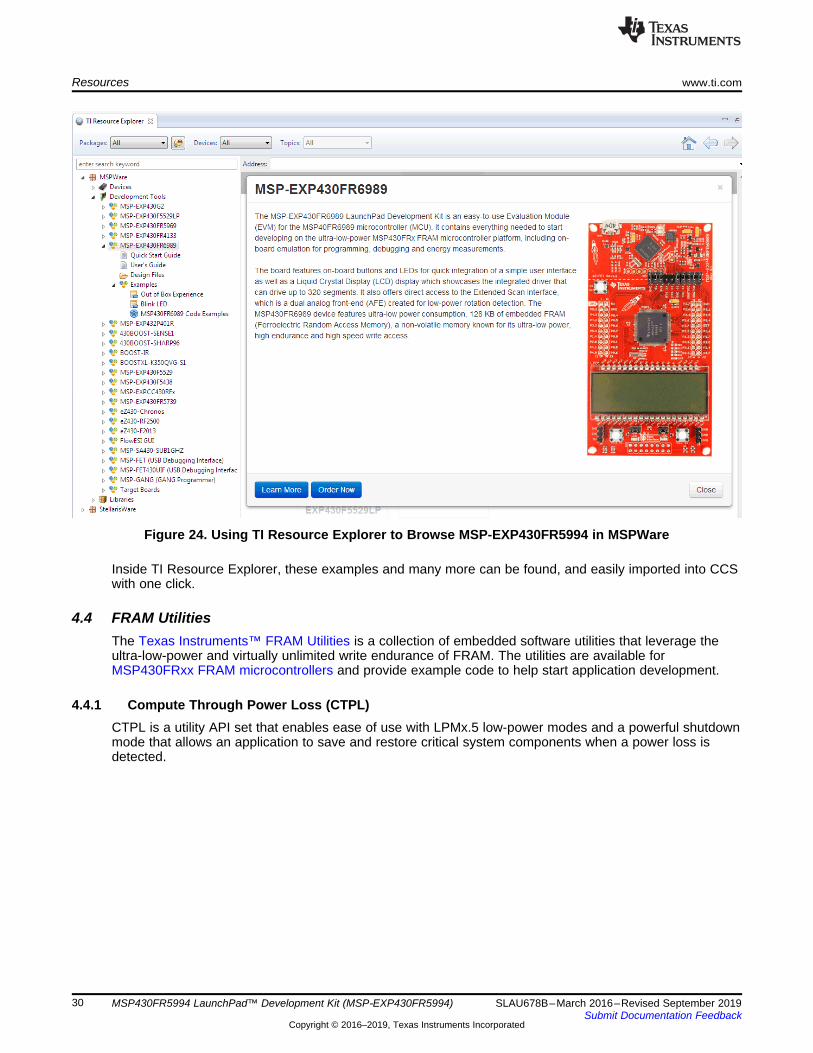
4.3 MSPWare and TI Resource ExplorerTI Resource Explorer is a tool integrated into CCS that allows you to browse through available designresources (see Figure 24). TI Resource Explorer helps you quickly find what you need inside packagesincluding MSPWare, ControlSuite, TivaWare, and more. TI Resource Explorer is well organized to findeverything quickly, and you can import software projects into your workspace in one click.
TI Resource Explorer Cloud is one of the TI Cloud Development tools, and it is tightly integrated with CCSCloud. See Section 4.1.1 for more information.
MSPWare is a collection of code examples, software libraries, data sheets, and other design resources forall MSP devices delivered in a convenient package–essentially everything developers need to becomeMSP experts.
In addition to providing a complete collection of existing MSP design resources, MSPWare also includes ahigh-level API called MSP Driver Library. This library makes it easy to program MSP hardware. For moreinformation, visit MSP430Ware for MSP Microcontrollers.
Resources www.ti.com
30 SLAU678B–March 2016–Revised September 2019Submit Documentation Feedback
Copyright © 2016–2019, Texas Instruments Incorporated
MSP430FR5994 LaunchPad™ Development Kit (MSP‑EXP430FR5994)
Figure 24. Using TI Resource Explorer to Browse MSP-EXP430FR5994 in MSPWare
Inside TI Resource Explorer, these examples and many more can be found, and easily imported into CCSwith one click.
4.4 FRAM UtilitiesThe Texas Instruments™ FRAM Utilities is a collection of embedded software utilities that leverage theultra-low-power and virtually unlimited write endurance of FRAM. The utilities are available forMSP430FRxx FRAM microcontrollers and provide example code to help start application development.
4.4.1 Compute Through Power Loss (CTPL)CTPL is a utility API set that enables ease of use with LPMx.5 low-power modes and a powerful shutdownmode that allows an application to save and restore critical system components when a power loss isdetected.
www.ti.com Resources
31SLAU678B–March 2016–Revised September 2019Submit Documentation Feedback
Copyright © 2016–2019, Texas Instruments Incorporated
MSP430FR5994 LaunchPad™ Development Kit (MSP‑EXP430FR5994)
4.5 MSP430FR5994 MCU
4.5.1 Device DocumentationAt some point, you will probably need more information about the MSP430FR5994 MCU. For every MSPdevice, the documentation is organized as shown in Table 12.
Table 12. How MSP Device Documentation is Organized
Document For MSP430FR5994 Description
Device familyuser's guide
MSP430FR58xx, MSP430FR59xx, andMSP430FR6xx Family User's Guide
Architectural information about the device,including all modules and peripherals such asclocks, timers, ADC, and so on.
Device-specificdata sheet
MSP430FR599x, MSP430FR596x Mixed-SignalMicrocontrollers
Device-specific information and all parametricinformation for this device
4.5.2 MSP430FR5994 Code ExamplesMSP430FR599x, MSP430FR596x Code Examples is a set of simple C examples that demonstrate how touse the entire set of MSP430 peripherals (including serial communication, ADC12, LCD_C, Timer_A,Timer_B, and others) through direct register access.
Every MSP derivative has a set of these code examples. When starting a new project or adding a newperipheral, these examples serve as a great starting point. There are also MSP Driver Library based codeexamples available in MSPWare.
4.5.3 MSP430 Application Notes and TI Reference DesignsVisit www.ti.com/msp430 for many application notes and reference designs with practical design examplesand topics.
4.6 Community Resources
4.6.1 TI E2E™ Support ForumsSearch the forums at e2e.ti.com. If you cannot find your answer, post your question to the TI experts.
4.6.2 Community at LargeMany online communities focus on the LaunchPad development kits (for example, http://www.43oh.com).You can find additional tools, resources, and support from these communities.

FAQ www.ti.com
32 SLAU678B–March 2016–Revised September 2019Submit Documentation Feedback
Copyright © 2016–2019, Texas Instruments Incorporated
MSP430FR5994 LaunchPad™ Development Kit (MSP‑EXP430FR5994)
5 FAQQ: I can't get the backchannel UART to connect. What's wrong?A: Check the following:• Do the baud rate in the host terminal application and the eUSCI settings match?• Are the appropriate jumpers in place, on the isolation jumper block?• Probe on RXD and send data from the host. If you don't see data, it might be a problem on the host
side.• Probe on TXD while sending data from the MSP. If you don't see data, it might be a configuration
problem with the eUSCI module.• Consider the use of the hardware flow control lines (especially for higher baud rates).
Q: The MSP G2 LaunchPad had a socket, allowing me change the target device. Why doesn't thisLaunchPad kit use one?A: This LaunchPad development kit provides more functionality, and this means using a device with morepins. Sockets for devices with this many pins are too expensive for the target price of the LaunchPaddevelopment kits.
Copyright © 2016, Texas Instruments Incorporated
www.ti.com Schematics
33SLAU678B–March 2016–Revised September 2019Submit Documentation Feedback
Copyright © 2016–2019, Texas Instruments Incorporated
MSP430FR5994 LaunchPad™ Development Kit (MSP‑EXP430FR5994)
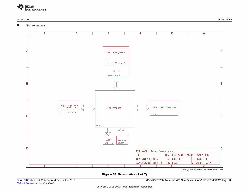
6 Schematics
Figure 25. Schematics (1 of 7)
Copyright © 2016, Texas Instruments Incorporated
Schematics www.ti.com
34 SLAU678B–March 2016–Revised September 2019Submit Documentation Feedback
Copyright © 2016–2019, Texas Instruments Incorporated
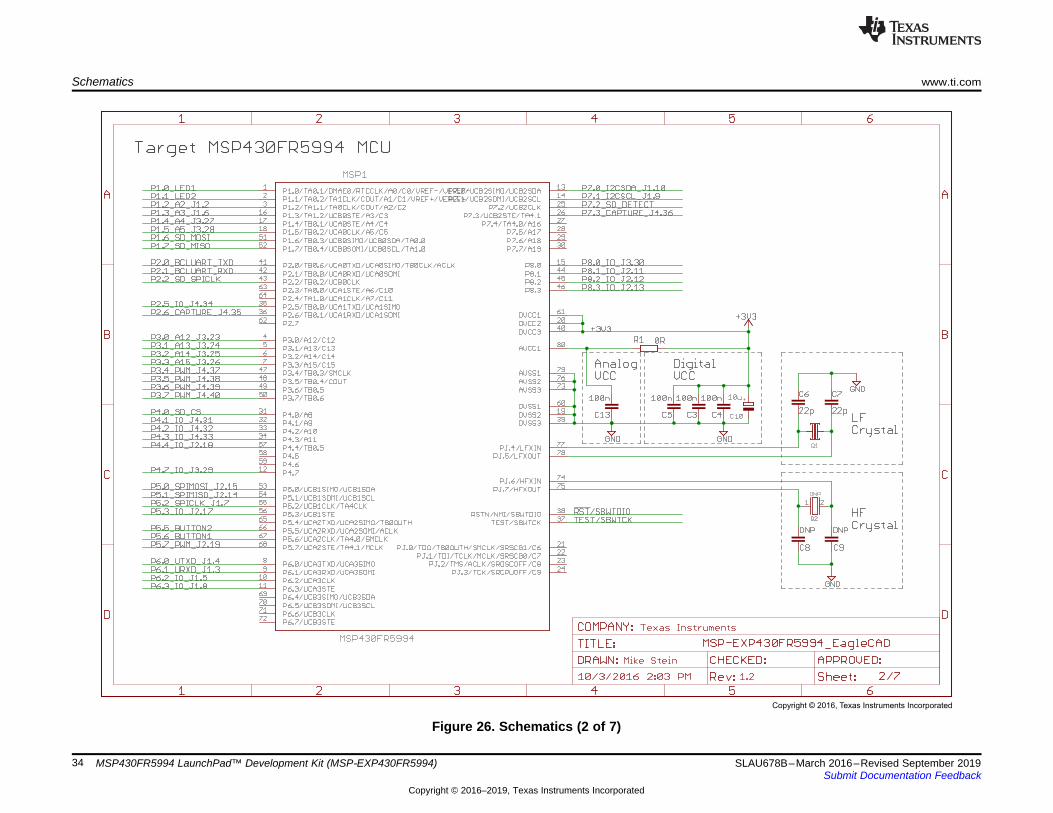
MSP430FR5994 LaunchPad™ Development Kit (MSP‑EXP430FR5994)
Figure 26. Schematics (2 of 7)
Copyright © 2016, Texas Instruments Incorporated
www.ti.com Schematics
35SLAU678B–March 2016–Revised September 2019Submit Documentation Feedback
Copyright © 2016–2019, Texas Instruments Incorporated
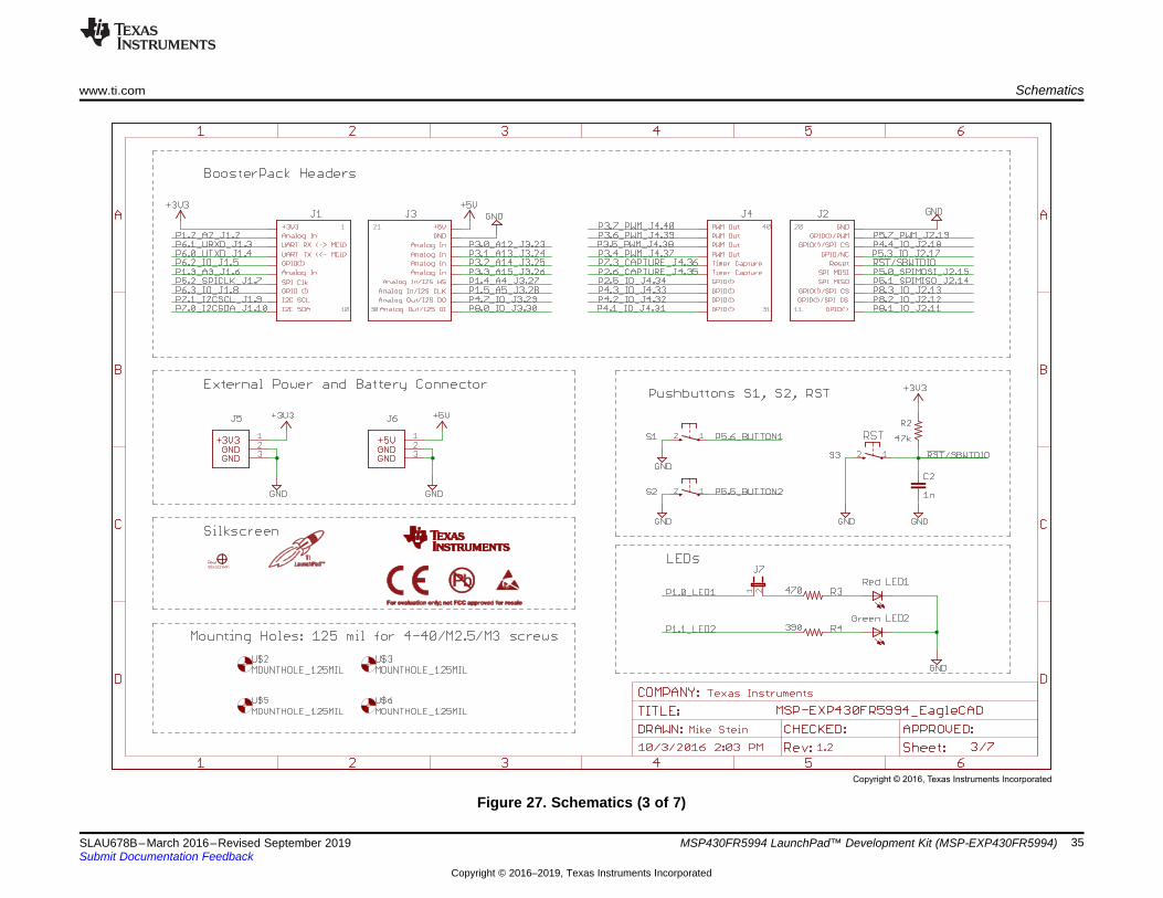
MSP430FR5994 LaunchPad™ Development Kit (MSP‑EXP430FR5994)
Figure 27. Schematics (3 of 7)
Copyright © 2016, Texas Instruments Incorporated
Schematics www.ti.com
36 SLAU678B–March 2016–Revised September 2019Submit Documentation Feedback
Copyright © 2016–2019, Texas Instruments Incorporated
MSP430FR5994 LaunchPad™ Development Kit (MSP‑EXP430FR5994)
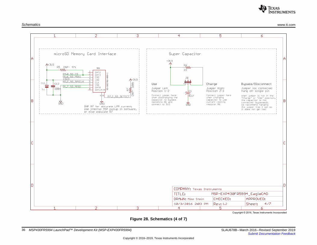
Figure 28. Schematics (4 of 7)
Copyright © 2016, Texas Instruments Incorporated
www.ti.com Schematics
37SLAU678B–March 2016–Revised September 2019Submit Documentation Feedback
Copyright © 2016–2019, Texas Instruments Incorporated
MSP430FR5994 LaunchPad™ Development Kit (MSP‑EXP430FR5994)
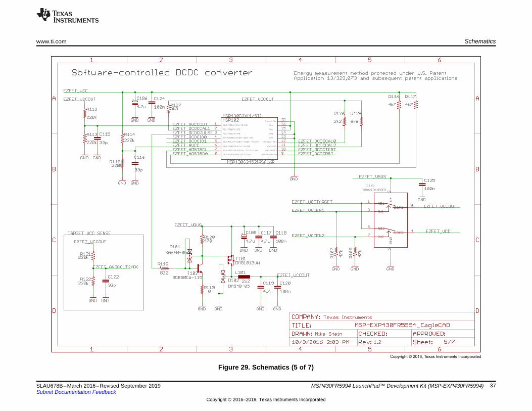
Figure 29. Schematics (5 of 7)
Copyright © 2016, Texas Instruments Incorporated
Schematics www.ti.com
38 SLAU678B–March 2016–Revised September 2019Submit Documentation Feedback
Copyright © 2016–2019, Texas Instruments Incorporated
MSP430FR5994 LaunchPad™ Development Kit (MSP‑EXP430FR5994)
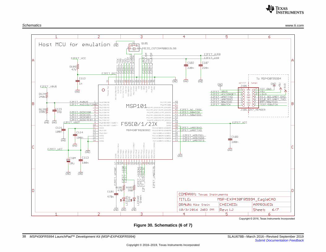
Figure 30. Schematics (6 of 7)
Copyright © 2016, Texas Instruments Incorporated
www.ti.com Schematics
39SLAU678B–March 2016–Revised September 2019Submit Documentation Feedback
Copyright © 2016–2019, Texas Instruments Incorporated
MSP430FR5994 LaunchPad™ Development Kit (MSP‑EXP430FR5994)
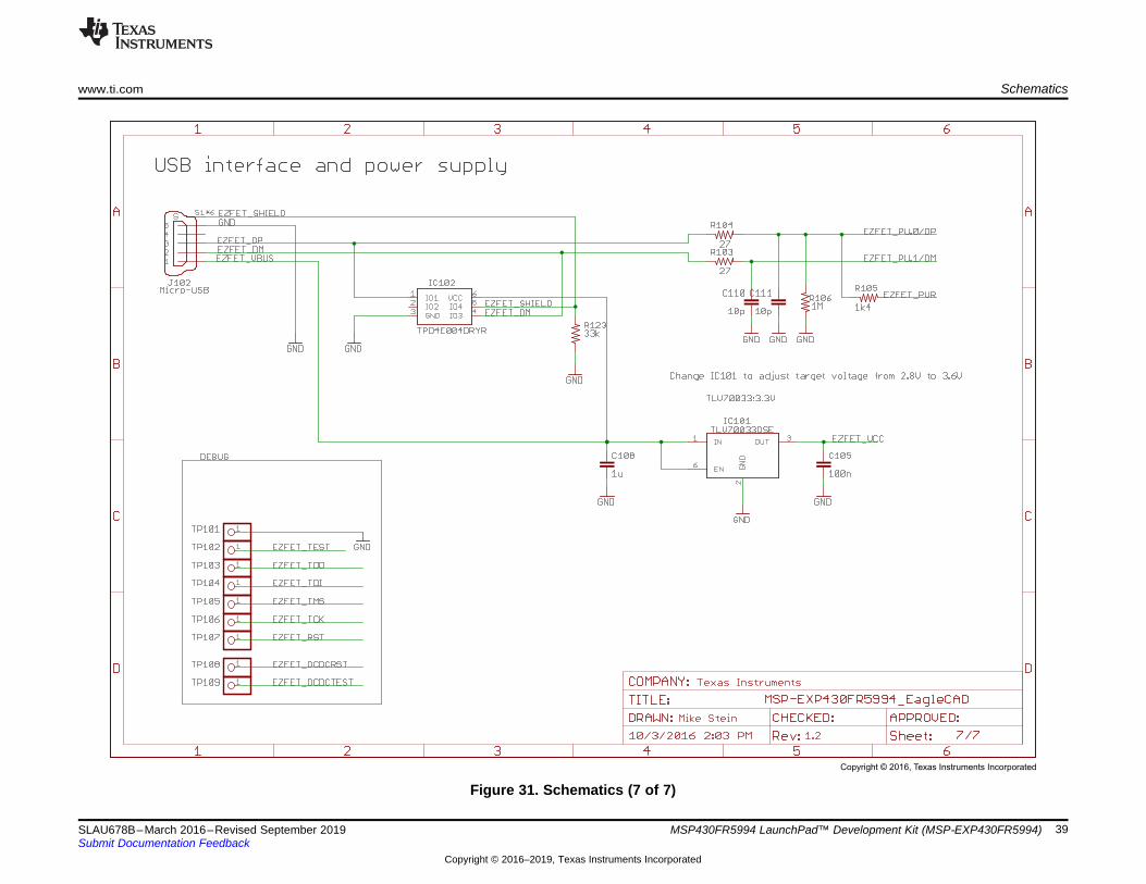
Figure 31. Schematics (7 of 7)

Revision History www.ti.com
40 SLAU678B–March 2016–Revised September 2019Submit Documentation Feedback
Copyright © 2016–2019, Texas Instruments Incorporated
Revision History
Revision HistoryNOTE: Page numbers for previous revisions may differ from page numbers in the current version.
Changes from April 27, 2016 to September 3, 2019 ....................................................................................................... Page
• Added BOOSTXL-SHARP128 as a supported BoosterPack module in Table 5, Software Examples ....................... 17• Changed required IAR Embedded Workbench IDE version to v6.40.2 in Table 6, IDE Minimum Requirements for MSP-
EXP430FR5994.......................................................................................................................... 17• Added BOOSTXL-SHARP128 as a supported BoosterPack module in Section 3.4.2, Operation............................ 24• Updated all figures in Section 6, Schematics ........................................................................................ 33

IMPORTANT NOTICE AND DISCLAIMER
TI PROVIDES TECHNICAL AND RELIABILITY DATA (INCLUDING DATASHEETS), DESIGN RESOURCES (INCLUDING REFERENCE DESIGNS), APPLICATION OR OTHER DESIGN ADVICE, WEB TOOLS, SAFETY INFORMATION, AND OTHER RESOURCES “AS IS” AND WITH ALL FAULTS, AND DISCLAIMS ALL WARRANTIES, EXPRESS AND IMPLIED, INCLUDING WITHOUT LIMITATION ANY IMPLIED WARRANTIES OF MERCHANTABILITY, FITNESS FOR A PARTICULAR PURPOSE OR NON-INFRINGEMENT OF THIRD PARTY INTELLECTUAL PROPERTY RIGHTS.These resources are intended for skilled developers designing with TI products. You are solely responsible for (1) selecting the appropriate TI products for your application, (2) designing, validating and testing your application, and (3) ensuring your application meets applicable standards, and any other safety, security, or other requirements. These resources are subject to change without notice. TI grants you permission to use these resources only for development of an application that uses the TI products described in the resource. Other reproduction and display of these resources is prohibited. No license is granted to any other TI intellectual property right or to any third party intellectual property right. TI disclaims responsibility for, and you will fully indemnify TI and its representatives against, any claims, damages, costs, losses, and liabilities arising out of your use of these resources.TI’s products are provided subject to TI’s Terms of Sale (www.ti.com/legal/termsofsale.html) or other applicable terms available either on ti.com or provided in conjunction with such TI products. TI’s provision of these resources does not expand or otherwise alter TI’s applicable warranties or warranty disclaimers for TI products.
Mailing Address: Texas Instruments, Post Office Box 655303, Dallas, Texas 75265Copyright © 2020, Texas Instruments Incorporated