Embed Size (px)
Citation preview

™
Multi 9™ System CatalogCatalog0860CT0201 R02/14
2014Class 860
CONTENTS
Description . . . . . . . . . . . . . . . . . . . . . . . . . . . . . . . . . . . . . . . . . . . . . PageContents Line 1 . . . . . . . . . . . . . . . . . . . . . . . . . . . . . . . . . . . . . . . . . Page x
Contents Line 2. . . . . . . . . . . . . . . . . . . . . . . . . . . . . . . . . . . . . . . . Page xContents Line 3 . . . . . . . . . . . . . . . . . . . . . . . . . . . . . . . . . . . . . . Page x
Master Pages
CONTENTS
Description . . . . . . . . . . . . . . . . . . . . . . . . . . . . . . . . . . . . . . . . . . . . . PageIntroduction. . . . . . . . . . . . . . . . . . . . . . . . . . . . . . . . . . . . . . . . . . . . . . . . . .7UL® and CSA® Rated Protection Devices . . . . . . . . . . . . . . . . . . . . . . . . .14IEC 60947-2 Rated Protection Devices . . . . . . . . . . . . . . . . . . . . . . . . . . .24Ground-Fault Protection Devices . . . . . . . . . . . . . . . . . . . . . . . . . . . . . . . .35Accessories . . . . . . . . . . . . . . . . . . . . . . . . . . . . . . . . . . . . . . . . . . . . . . . .44Additional System Devices. . . . . . . . . . . . . . . . . . . . . . . . . . . . . . . . . . . . .64Dimensions. . . . . . . . . . . . . . . . . . . . . . . . . . . . . . . . . . . . . . . . . . . . . . . . .72Applications . . . . . . . . . . . . . . . . . . . . . . . . . . . . . . . . . . . . . . . . . . . . . . . .84Time/Current Curves . . . . . . . . . . . . . . . . . . . . . . . . . . . . . . . . . . . . . . . . .91Let-Through Curves . . . . . . . . . . . . . . . . . . . . . . . . . . . . . . . . . . . . . . . . . .96Index of Part Numbers . . . . . . . . . . . . . . . . . . . . . . . . . . . . . . . . . . . . . . .103


™
© 2008–2014 Schneider Electric All Rights Reserved 3
0860CT0201 R02/14 Multi 9™ System CatalogTable of Contents
Table of ContentsSECTION 1: INTRODUCTION .............................................................. 7
Multi 9™ Products for Equipment Applications ........................................... 7System Flexibility ................................................................................... 7Advantages ........................................................................................... 8
Conformance to Standards ......................................................................... 9Overview ............................................................................................... 9UL 489/CSA C22.2 No.5 Standard–Branch Circuit Protection .............. 9UL 1077 Standard—Supplementary Protection within the Product ..... 10Comparing Terminology for UL 489/CSA C22.2 No.5 and 1077 Stan-dards ................................................................................................... 11UL 489A Standard—DC Telecommunication Applications ................. 12UL 486 Standard—Connection Terminals ........................................... 12IEC 60947-2 Standard ......................................................................... 12IEC 60898 Standard ............................................................................ 12CSA C22.2 Standard ........................................................................... 12CCC Mark ............................................................................................ 12UL 508 Standard—Manual Motor Controllers ..................................... 12
SECTION 2: UL® AND CSA® RATED PROTECTION DEVICES ....... 14
UL 489/CSA C22.2 No.5 Listed 240 Vac C60 Circuit Breakers (AC) ....... 16Standard Features ............................................................................... 16Connections ........................................................................................ 17Standards ............................................................................................ 17Catalog Numbers ................................................................................ 18
UL 489/CSA C22.2 No. 5 Listed 480Y/277 Vac C60 Circuit Breakers (AC) ........................................................................................... 19
Benefits ............................................................................................... 19Standard Features ............................................................................... 19Connections ........................................................................................ 20Standards ............................................................................................ 20Catalog Numbers ................................................................................ 20
UL 489/CSA C22.2 No. 5 Listed C60 Circuit Breakers (DC) .................... 21Overview ............................................................................................. 21Catalog Numbers ................................................................................ 21
UL 1077 Recognized C60 Supplementary Protectors .............................. 22Standards ............................................................................................ 22Standard Features ............................................................................... 23Catalog Numbers ................................................................................ 23
SECTION 3: IEC 60947-2 RATED PROTECTION DEVICES ............. 24
DPN-N Phase + Neutral Circuit Breakers ................................................. 25Time/Current Curves ........................................................................... 25Accessories ......................................................................................... 25Standards ............................................................................................ 25Catalog Numbers ................................................................................ 26
IEC Rated C60 Miniature Circuit Breakers ............................................... 27Standard Features ............................................................................... 27Catalog Numbers ................................................................................ 28Catalog Numbers ................................................................................ 29Catalog Numbers ................................................................................ 30
C60L Instantaneous Circuit Breakers (Icb) (Curve MA) ............................ 31Coordination of C60L-MA Circuit Breaker, Thermal Relay and Contactor ...................................................................................... 31
IEC Rated C120H Circuit Breakers ........................................................... 33Standard Features ............................................................................... 33

™
Multi 9™ System Catalog
412/2013 © 2008–2014 Schneider Electric
All Rights Reserved
Accessories ......................................................................................... 34Standards ............................................................................................ 34Catalog Numbers ................................................................................. 34
SECTION 4: GROUND-FAULT PROTECTION DEVICES .................. 35
Selection Table ......................................................................................... 35UL 1053 Listed GFP Ground Fault Protectors .......................................... 36
Standards ............................................................................................ 36Catalog Numbers ................................................................................. 37
IEC Rated ID Residual Current Switches .................................................. 38Standards ............................................................................................ 39Catalog Numbers ................................................................................. 39
IEC Rated C60 VigiTM Modules for Ground-fault Protection ..................... 40Accessories ......................................................................................... 41Standards ............................................................................................ 41Catalog Numbers ................................................................................. 41
IEC Rated C120 Vigi Residual Current Circuit Breakers ........................... 42Standards ............................................................................................ 42Catalog Numbers ................................................................................. 42
DPN-N Vigi Residual Current Circuit Breaker ........................................... 43Function ............................................................................................... 43Catalog Numbers ................................................................................. 43Standards ............................................................................................ 43
SECTION 5: ACCESSORIES .............................................................. 44
Technical Data ..................................................................................... 45Breaking Capacity ............................................................................... 45Endurance ........................................................................................... 45Dimensions .......................................................................................... 45Weight ................................................................................................. 46
Electrical Auxiliaries .................................................................................. 46MN Undervoltage Release .................................................................. 47
MN Time-delayed Undervoltage Release ..................................... 47MX + OF Shunt Trip and Auxiliary Switch ........................................... 48OF Auxiliary Switch ............................................................................. 48OFS Auxiliary Switch and Adapter (for GFP and ID RCD) .................. 48SD Alarm Switch .................................................................................. 49
Comb Bus Bars ......................................................................................... 50UL Recognized C60 Comb Bus Bars ......................................................... 50Tooth Caps for UL Recognized Comb Bus Bars ................................. 50Connection Comb Bus Bars for C60 UL 1077 Circuit Breakers .......... 51Connection Comb Bus Bars for C60 UL489 Circuit Breakers ............. 52IEC Rated C60 Comb Bus Bars .......................................................... 53End Caps for IEC Rated C60 Comb Bus Bars .................................... 54Connector for IEC Rated Comb Bus Bars ........................................... 54Tooth Caps for IEC Rated Comb Bus Bars ......................................... 54
Device Shielding ....................................................................................... 54DIN Rail Spacer ................................................................................... 54Terminal Screw Shields ....................................................................... 55Terminal Covers .................................................................................. 55Ring Lug Terminal Kit .......................................................................... 55
Identification System ................................................................................. 56Snap-on Marking Symbols .................................................................. 56
Operation Devices ..................................................................................... 57Rotary Handles .................................................................................... 57Padlock Attachments ........................................................................... 57
Mounting Accessories ............................................................................... 59Plug-in Base ........................................................................................ 59

™
Multi 9™ System Catalog
512/2013© 2008–2014 Schneider Electric
All Rights Reserved
Front Mounting Bracket (Kit) ............................................................... 59DIN Rail Mounting Clips ...................................................................... 60UL/CSA Recognized Mounting Base for Multi 9 C60 Circuit Breakers .....60US Mounting Base Accessories .......................................................... 61
Wire Lug Kit ................................................................................... 61MSC IEC Mounting Base .................................................................... 62Multi-Pole Front Mounting Kit .............................................................. 63Pole Filler ............................................................................................ 63
SECTION 6: ADDITIONAL SYSTEM DEVICES ................................. 64
CM Selector Switches ......................................................................... 64I Current Isolating Switch .................................................................... 66
Status, Display and Control Accessories .................................................. 67V Signal Lamp ..................................................................................... 67BP Push Buttons ................................................................................. 68CH Hour Counter ................................................................................. 69CI Impulse Counter ............................................................................. 69
Kaedra™ Weatherproof DIN Type Enclosures ......................................... 70Applications ......................................................................................... 70Standard Features ............................................................................... 70Construction ........................................................................................ 70Installation ........................................................................................... 70Accessories ......................................................................................... 71
SECTION 7: DIMENSIONS ................................................................. 72
UL 489/CSA C22.2 No. 5 Listed C60 Circuit Breakers ............................. 72UL 1077 Supplementary Protectors .......................................................... 73IEC Rated Circuit Breakers ...........................................................................73UL and IEC Rated Ground-Fault Products ............................................... 74Accessory Dimensions .............................................................................. 75Kaedra Weatherproof Mini-Enclosure Dimensions ................................... 81Kaedra Weatherproof Enclosures ............................................................. 82
SECTION 8: APPLICATIONS ............................................................. 84
Degree of Protection (IP) .......................................................................... 84Vibration .............................................................................................. 85Mechanical Shock (IK) ........................................................................ 85Protection of 400 Hz Circuits ............................................................... 85
Temperature Rating .................................................................................. 86Typical IEC Grounding Systems ............................................................... 89
Codification of the Grounding Systems ............................................... 89The TT Grounded Neutral System ...................................................... 89The IT Grounding System ................................................................... 90The TN-S Grounding System .............................................................. 90
SECTION 9: TIME/CURRENT CURVES ............................................. 91
UL 489/CSA C22.2 No. 5 & UL 489A Listed C60 Miniature Circuit Breakers .91UL 1077 Recognized Supplementary Protectors ...................................... 92IEC60947-2 Rated D PN-N Circuit Breakers ............................................ 93Alternative Current 50/60 Hz ..................................................................... 94Motor Curve .............................................................................................. 95
SECTION 10: LET-THROUGH CURVES .............................................. 96
UL Listed C60 Miniature Circuit Breakers and UL Recognized C60Supplementary Protectors ........................................................................ 96

™
Multi 9™ System Catalog
612/2013 © 2008–2014 Schneider Electric
All Rights Reserved
Limitation curves ..................................................................................... 100
INDEX OF PART NUMBERS ....................................... 103

™
Multi 9™ System CatalogSection 1—Introduction
702/2014© 2008–2014 Schneider Electric
All Rights Reserved
Section 1—Introduction
Multi 9™ Products for Equipment Applications
Multi 9 modular system of miniature circuit breakers and supplementary protectors, accessories, and peripherals provides protection of equipment or especially sensitive circuits within the equipment. Installation labor and space are both minimized by the modular architecture of the Multi 9 system, whether a single protective device or multiple devices with their accessories are being used.
Schneider Electric offers an extensive line of UL 489/CSA C22.2 No.5 Circuit Breakers and UL 1077 Supplementary Protectors. In addition, a variety of IEC certified Circuit Breakers and Accessories are available for an original equipment manufacturer (OEM) whose products are destined for export beyond North America. To an OEM, this means that one family of electrical protection products can be used regardless of equipment destination.
The Standards include:
Potential applications include semi-conductor machines, communication equipment, process control panels, computers, medical equipment, electronic controls, transformers, power supplies, and other electrical equipment.
System Flexibility
The Multi 9 System includes an extensive line of field-installable accessories. Plug-on electrical auxiliaries include shunt trip, undervoltage release, auxiliary switch, and alarm switch. Other protection devices include residual current devices, dc circuit breakers, and switches. Control and display devices include signal lamps, push buttons, and motor operators. There are also mechanical accessories for locking, operating, shielding, mounting, etc. The following diagram shows many of the Multi 9 system accessories.
• UL 489 Standard for Circuit Breakers• UL 489A Standard for DC Communication Applications• UL 1077 Standard for Supplementary Protectors• UL 1053 Ground Fault Sensing and Relaying Equipment• IEC 60947-2 Low-voltage switchgear and controlgear - Part
2: Circuit-breakers
• CSA C22.2 No. 5 Standard for Circuit Breakers• CSA C22.2 No. 235 Supplementary Protectors• CCC Pending• C60 Miniature Circuit Breakers are RoHS Compliant
Figure 1: Functional Diagram of Multi 9 System
CIImpulseCounter
CHHour
Counter
VSignalLamp
VSignalLamp
BPPush
Button(N.O.)
orSignal
BPPush
Button(N.C.)
orSignal
TMMotor
Operator
SDAlarmSwitch
OFAux
Switch
MX + OFShuntTrip
&Aux
Switch
MNUnder-voltageRelease
C60Circuit
Breaker
Vigi or GFPResidual
Current Device
IHandIHPTime
Switches
ISwitch
CMSelectorSwitch
DPN-NResidualCurrentCircuit
Breaker
OFS&
Elect.Accessory
GFPGround
FaultProtector
Status and Display Output
Plug-on Electrical Auxiliaries
Other devices used with or instead of the C60 device
Protected Line
Control Inputs
Switch or Control
MeteringDevice
0860
3577

™
Multi 9™ System Catalog Section 1—Introduction
802/2014 © 2008–2014 Schneider Electric
All Rights Reserved
Advantages
Multi 9 C60 circuit breakers and supplementary protectors provide several features which are important to OEMs. These include:
• Small, compact size• Easy installation on DIN rails• Limits let-thru current• Resetability, more convenient than fuses• Electrical auxiliaries for control and status information• Extensive variety of accessories
Better Protection—Multi 9 supplementary protectors and miniature circuit breakers limit let-through current, providing faster separation of the component from the fault, thereby reducing system damage.
More Selection—More ratings compatible with low-power electronic circuits are available in the range from 0.5 to 10 A. Others are provided in convenient steps, up to 63 A for the C60 products.
Reduction of Nuisance Tripping—Available with different trip characteristics to meet system needs: B, C and D curves, depending on the model.
Panel Space Savings—Multi 9 products are compact. Width per pole is only 0.71 in. (18 mm) for the C60 circuit breaker. All of the products are built in a consistent format with incremental widths of 0.35 in. (9 mm) (therefore the name Multi 9).
Simple Installation—The Multi 9 products mount easily onto a 35 mm DIN mounting rail. Large box lug terminals (pressure plate type) are suitable for use with copper wiring up to 2 AWG for C60 circuit breakers and supplemental protectors.
Reverse Feeding— Reverse feeding of line power is permitted.
Reliability—Each C60 miniature circuit breaker has an endurance of 10,000 operation cycles and voltage withstand of 6000 V impulse rating.
World-Wide Availability—The Multi 9 products are available and supported throughout the world by Schneider Electric.
From the Power Distribution Specialists—Schneider Electric can be your single source of protection equipment, with a comprehensive line of products for OEM products or the factory. In addition to the Multi 9 circuit breakers and supplementary protectors, these products include the following:
• QO® and QOU Miniature Circuit Breakers 10–125 A• Compact® Molded Case Circuit Breakers 15–3200 A• Powerpact® Molded Case Circuit Breakers 15–3000 A• Masterpact® Universal Power Circuit Breakers 250–6300 A
Figure 2: UL 489/CSA C22.2 No. 5 Listed Multi 9 C60 Circuit Breakers
1P 3P2P

™
Multi 9™ System CatalogSection 1—Introduction
902/2014© 2008–2014 Schneider Electric
All Rights Reserved
Conformance to Standards
Overview
Multi 9 circuit protection products conform to the standards most needed by OEMs—UL 489/CSA C22.2 No.5, UL 1077, CSA C22.2 No. 235, and IEC 60947-2.
Different applications call for circuit protection devices that meet different standards. The Multi 9 family allows OEMs to use a single family of products in their equipment, whether it is destined for the United States, Canada or an international market outside of North America. A variety of Multi 9 devices are tested per Underwriters Laboratories® (UL®) and Canadian Standards Association® (CSA®) Standards as required by the National Electrical Code® (NEC®) in the United States and the Canadian Electrical Code (CEC) in Canada. They are also tested per the standards of the International Electrotechnical Commission®
(IEC®) and may therefore be used in International Markets where these products meet the requirements.
In this catalog, the products are grouped by the standards they are designed to meet, including:
• UL 489—Defines rigorous testing requirements for circuit breakers in the United States
• CSA C22.2 No. 5—Defines rigorous testing requirements for circuit breakers in Canada• CSA C22.2 No. 235—Defines requirements for supplementary protectors• UL 489A—Limited applications (dc circuits in communications equipment) • UL 1077—Defines supplementary protectors for use within electrical equipment protected by
branch circuit breakers • IEC 60947-2—International standards for circuit breakers to be used in industrial applications
UL 489/CSA C22.2 No.5 Standard–Branch Circuit Protection
An OEM product as a whole must be appropriately protected from overcurrent conditions, either by connection in the field to a protected branch circuit (in accordance with NEC) or by inclusion of branch circuit protection within the product itself. In the United States, these branch circuit protection devices must comply with the UL 489/CSA C22.2 No.5 Standard for Molded-Case Circuit Breakers. (see UL 489/CSA C22.2 No.5 No. 1 in Figure 3, which is a drawing of a hypothetical piece of OEM equipment requiring multiple protection devices.)
Applications Requiring UL 489/CSA C22.2 No.5 Listed Circuit Breakers
In some instances, the protective devices being installed in equipment must comply with UL 489/CSA C22.2 No.5. These include the following situations:
1. If a circuit such as a convenience receptacle could leave the equipment, that circuit must be protected by a UL 489/CSA C22.2 No.5 branch circuit protection device (see UL 489/CSA C22.2 No.5 No. 2).
2. If a circuit such as to an external motor could leave the equipment, that circuit must be protected by a UL 489/CSA C22.2 No.5 branch circuit protection device (see UL 489 No. 3).
3. Motors within the equipment should also be protected by a UL 489/CSA C22.2 No.5 device (see UL 489 No. 4).
4. All equipment which requires HACR (Heating, Air Conditioning, and Refrigeration) rating must be protected by a UL 489/CSA C22.2 No.5 branch circuit protection device (see UL 489 No. 5).
NOTE: The motor control circuit may be protected by a UL 1077 device. It must also have over current protection even though there is a UL 1077 device downstream.
In general, a UL 489/CSA C22.2 No.5 circuit breaker could also be used in any application for which a UL 1077 device is allowed, since the UL 489/CSA C22.2 No.5 devices meet or exceed the requirements of UL 1077 devices. The converse of this is not true, since UL 1077 devices cannot meet the more stringent UL 489/CSA C22.2 No.5 Standard.

™
Multi 9™ System Catalog Section 1—Introduction
1002/2014 © 2008–2014 Schneider Electric
All Rights Reserved
UL 1077 Standard—Supplementary Protection within the Product
Within the OEM product itself, additional (supplementary) protection for sensitive or critical internal circuitry may be provided by one or more supplementary circuit protectors. A supplementary protector is an overcurrent protection device which is specifically designed for OEM applications and which complies with UL 1077 Standard for Supplementary Protectors for Use in Electrical Equipment.
Under UL 1077, supplementary protectors may be used under the following conditions:
• When branch overcurrent protection is already provided• If short-circuit protection is needed for sensitive devices within the equipment• When wiring connected to the supplementary protector does not exit the equipment to external
devices such as receptacles or motors• If the UL 1077 device does not provide the only means of disconnecting the product
The following applications illustrated in Figure 3 allow the use of UL 1077 supplementary protectors:
• The supplementary protection is used to supplement or provide additional protection to sensitive components inside the equipment (see UL 1077 No. 1). A UL 489/CSA C22.2 No.5 circuit breaker must be located upstream from the equipment.
• Critical or sensitive internal circuitry (see UL 1077 No. 2) such as: Computers and microprocessors, communications equipment, electronic controllers, power supplies and many other types of equipment
• Motor control circuits may be protected by a UL 1077 device, unless the circuit includes a transformer (in which case a UL 489/CSA C22.2 No.5 device is required).

™
Multi 9™ System CatalogSection 1—Introduction
1102/2014© 2008–2014 Schneider Electric
All Rights Reserved
NOTE: This is a simplified summary of the standards. Refer to applicable codes for specific applications.
Comparing Terminology for UL 489/CSA C22.2 No.5 and 1077 Standards
The terms used to differentiate these products can cause confusion if a user is not careful. Misapplying the terms may result in misapplication of the products.
Any one of the following terms can be used to identify supplementary protectors:
Any of the following terms can be used to identify circuit breakers:
Figure 3: Guidelines for Application of UL 489/CSA C22.2 No.5 Circuit Breakers and UL 1077 Supplementary Protectors
1
2
3
4
5
1
1
2
3
2
3
2
1
3
5
4
Equipment Enclosure
Feeder or BranchCircuit UL 489/CSA C22.2 No.5 Listed Molded Case Circuit Breaker (MCCB)
or Miniature Circuit Breaker (MCB)
Protected by BranchCircuit Breaker
Electronics
OtherSensitiveDevices
MiscellaneousDevices
ExternalMotor
InternalMotor
MotorControl
HACR
UL 489
UL 489
UL 489
UL 1077
UL 1077
UL 1077
UL 489InternalReceptacle
ExternalReceptacle
UL 1077Applications Permitting Supplementary Protectors
Supplements or provides additional protection for sensitive electronics inside the equipment.
Used on the load side of branch circuit protection to protect critical or sensitive internal circuitry such as:• Computers and microprocessors• Communications equipment• Electronic controllers• Power supplies• Many other types of equipment
Permitted for protection of motor control circuitsNEC 430-72, unless transformers are in circuit, then UL 489/CSA C22.2 No.5.
UL 489/CSA C22.2 No.5Applications Requiring Branch Circuit Protection
Protects conductors entering the OEM equipment. This required UL 489/CSA C22.2 No.5 device may be provided integral to the OEM equipment or beexternal as part of the distribution system. May act as branch circuit protection if it protects the conductor to the utilization equipment.
Required to protect convenience receptacle circuits(internal or external)
Required to protect an external load circuit leavingthe equipment
Required for motors in the equipment
Required for HACR equipment (Heating, Air Conditioning, and Refrigeration)
0860
3335
• Supplementary protector• UL Recognized • UL 1077 • The UL symbol
• Circuit breaker• UL Listed• UL 489/CSA C22.2 No.5• The UL symbol

™
Multi 9™ System Catalog Section 1—Introduction
1202/2014 © 2008–2014 Schneider Electric
All Rights Reserved
UL 489A Standard—DC Telecommunication Applications
The UL 489A Standard covers dc rated circuit breakers intended to provide branch circuit protection in telecommunications equipment. The products are marked as UL Listed circuit breakers for use in telecommunication equipment.
UL 486 Standard—Connection Terminals
The UL 486 Standard applies to compression wiring connection terminals. It is a requirement for connections of a UL 489/CSA C22.2 No.5 circuit breaker. Although it is not a requirement for UL 1077 Recognized devices, UL 486 Rated terminals are included on those Multi 9 products. This allows the user to apply field wiring directly to any of these devices, without using intermediate, UL rated terminal blocks.
The connectors on Multi 9 devices are Rated UL 486A-B, which applies to copper conductors.
These standards apply to field-wired terminals that are an integral part of the equipment. Criteria includes static heating tests, secureness tests, and pull-out tests.
IEC 60947-2 Standard
In countries which follow the IEC Standards, IEC 60947-2 is used for most industrial applications of circuit protection. IEC 60947-2 does not distinguish between the two levels of protection equivalent to UL 489/CSA C22.2 No.5 circuit breakers and 1077 supplementary protectors. Therefore, in equipment like that illustrated in figure 3, if IEC guidelines apply, then all of the devices could be selected from the IEC Rated portion of this catalog.
IEC 60898 Standard
The IEC 60898 Standard is less stringent than 60947-2. It applies primarily to residential applications of circuit breakers in countries adhering to IEC Standards, and is not generally applicable to OEMs.
CSA C22.2 Standard
The CSA (Canadian Standards Association) C22.2 Standards closely correspond to the UL Standards: CSA C22.2 No. 5-02 (harmonized to UL 489/CSA C22.2 No.5) and CSA C22.2 No. 235 (equivalent to UL 1077). All UL rated devices also have the corresponding CSA rating, unless otherwise noted.
CCC Mark
The China Compulsory Certification (CCC) mark is a new safety and quality mark system. Compulsory Product Certification System (CPCS) prohibits the sale or importation of equipment under the scope of the law that does not bear the CCC Mark issued by a Designated Certification Body (DCB). The CCC Mark covers both safety and Electromagnetic compatibility.
The CPCS regulates twenty-two different product groups, which include the following:
Electrical wires and cables; switches for circuits, installation protective and connection devices; low-voltage electrical apparatus; small power motors; electric tools; welding machines; household and similar electrical appliances; audio and video apparatus; information technology equipment; lighting apparatus; telecommunications terminal equipment; motor vehicles and safety parts; motor vehicle tires; safety glass; agricultural machinery; latex products; medical devices; fire fighting equipment; detectors for intruder alarm systems; wireless local area network equipment; security and protection equipment; and decoration and renovation products.
UL 508 Standard—Manual Motor Controllers
UL Standard 508 covers industrial control equipment, specifically for motor control functions. It covers individual devices as well as assemblies.
CCC Mark

™
Multi 9™ System CatalogSection 1—Introduction
1302/2014© 2008–2014 Schneider Electric
All Rights Reserved
There are UL 508 Listed manual motor controllers that look much like miniature circuit breakers, and have thermal settings and instantaneous settings similar to circuit breakers. These are specialized devices and cannot be used for a wide range of applications, as can UL 1077 and UL 489/CSA C22.2 No.5 devices.
Like UL 1077 supplementary protectors, a UL 508 Listed manual motor controller (or a group of them) must be protected by a UL 489/CSA C22.2 No.5 Listed branch circuit breaker.
Manual motor controllers are available from Schneider Electric (Telemecanique products GV2 and GV3) but are not included in this catalog.
Table 1: Comparison Summary of Applicable UL and IEC Standards
Characteristic UL 489/CSA C22.2 No. 5 UL 1077/CSA C22.2 No. 235 IEC 60947-2
Labeling UL Listed UL Recognized component IEC Certified device
Nomenclature Circuit breakers Supplementary protectors Circuit breakers or supplementary protectors
Dielectric test (for 240 Vac)
2 times rated plus 1000 V for 1 minute (1,480 at 240 Vac)
2 times rated plus 1,000 V for 1 minute (1,480 at 240 Vac) 1,500 V
Interrupting rating 10 kA at 240 Vac 10 kA at 240 Vac 20 kA at 240 Vac
Overload protection 50 operations at 600% rating 50 operations at 150% rating 12 operations at 600% rating
Service capacity Must be operational after two interruptionsMay be tested in series with branch circuit device and may become inoperable after test
Must be operational after two interruptions
Calibration test 200% In, 2 minutes max. (0–30 A) Per manufacturer’s trip curve At 200% In, time shall not exceed manufacturer’s stated value
Calibration temperature 25°C (77°F), unless other value specified by manufacturer Manufacturer must specify Manufacturer must specify
Testing temperature 25°C (77°F) ambient, 50°C (122°F) rise max. at terminals
25°C (77°F) ambient, 50°C (122°F) rise max. at field wiring terminals; 65°C (149°F) rise max. on factory wiring terminals
At 25°C (77°F) ambient, 80°C (176°F) rise max. at terminals
Endurance6000 operations at rated current and voltage, 75-80% PF, plus 4000 operations at no load
6000 operations at rated current and voltage, 75-80% PF
1500 operations at rated current and voltage, 75-80% PF
Air spacing 3/4 in. (20.1 mm) 3/8 in. (9.53 mm) See dielectric
Surface spacing 1-1/4 in. (31.8 mm) 1/2 in. (12.7 mm) See dielectric
Test and follow up tests Initial, periodic and quarterly follow-up tests observed by UL representative
Initial tests observed by UL representative, plus quarterly visual follow-up inspection by UL
Conducted by manufacturer

™
Multi 9™ System Catalog Section 2—UL® and CSA® Rated Protection Devices
1402/2014 © 2008–2014 Schneider Electric
All Rights Reserved
Section 2—UL® and CSA® Rated Protection Devices
The Multi 9 system includes several families of miniature circuit protection devices that have the UL ratings required in the United States and some other countries. The products are summarized below and are described in detail on the following pages. They include the following families:
• UL Listed C60 240 V Circuit Breakers (UL 489/CSA C22.2 No.5)• UL Listed C60 480 V Circuit Breakers (UL 489/CSA C22.2 No.5)• UL Listed C60 Circuit Breakers for use in Communication Equipment (UL 489A) not CSA certified• UL Recognized C60 Supplementary Protectors (UL 1077 and CSA C22.2 No. 235)
NOTE: Protection devices with only IEC ratings are described in Section 3, while accessories for both the UL and IEC devices are described in Section 5.
Table 2: Specifications for UL 489/CSA C22.2 No.5 Circuit Breakers
Ratings per UL Standards UL 489/CSA C22.2 No.5 C60(240 Vac)
UL 489/CSA C22.2 No.5 C60 (480Y/277 Vac)
Number of Poles 1P 2P 3P 1P 2P 3P
Rated Current at 77°F (25°C) 0.5–20 A 25–35 A 0.5–35 A 0.5–35 A 0.5–20 A 1–20 A 1–20 A
Interrupting Ratingsas per UL 489/CSA C22.2 No.5
AC 50/60 Hz
120 V240 V277 V480Y/277 V
10 kA10 kA
——
10 kA5 kA——
—10 kA
——
—10 kA
——
10 kA10 kA10 kA
—
—10 kA10 kA10 kA
—10 kA10 kA10 kA
DC60 V125 V
10 kA—
10 kA10 kA
——
——
——
——
Ultimate Breaking Capacity (Icu)as per IEC 60947-2 AC 50/60 Hz
240 V415 V440 V
10 kA10 kA
—
20 kA10 kA6 kA
20 kA10 kA6 kA
10 kA10 kA
—
10 kA10 kA6 kA
10 kA10 kA6 kA
Service Breaking Capacity (Ics) (%Icu) 75% 75% 75% 75% 75% 75% 75%
Magnetic Setting (Times Ampere Rating)
B curveC curveD curve
—7 to 10
10 to 14
—7 to 10 10 to 14
Dimensions (in./mm)
Width 0.71/18 0.71/18 1.42/36 2.13/54 0.71/18 1.42/36 2.13/54
Heightbox/boxring/ring1
box/ring
4.21/1074.86/123.44.54/115
4.21/1074.86/123.44.54/115
4.21/1074.86/123.44.54/115
4.21/1074.86/123.44.54/115
5.56/1415.56/141
—
5.56/1415.56/141
—
5.56/1415.56/141
—
Depth 3.00/76 3.00/76 3.00/76 3.00/76 3.00/76 3.00/76 3.00/76
Weight (oz./g) max.box/boxring/ringbox/ring
4.4/1365.2/1614.8/148
4.4/1365.2/1614.8/148
8.7/27110.3/3219.5/297
13.1/40715.5/48214.3/445
5.3 (166)5.3 (166)
—
10.6/33210.6/332
—
15.9 (498)15.9 (498)
—1 Fingersafe 240 V C60 circuit breaker ring terminal dimensions are same as the 480 V C60 circuit breaker.

™
Multi 9™ System CatalogSection 2—UL® and CSA® Rated Protection Devices
1502/2014© 2008–2014 Schneider Electric
All Rights Reserved
Figure 4: UL 1077 Recognized C60 Supplementary Protectors
Table 3: Specifications for UL 1077 Recognized Supplementary Protectors
Ratings per UL Standards UL 1077 C60
Number of Poles 1P 2P 3P 4P
Rated Current at 77°F (25°C) 0.5–63 A 0.5–63 A 0.5–63 A 0.5–63 A
Interrupting Ratings as per UL 1077
50/60 Hz
120 Vac240 Vac277 Vac480Y/277 Vac
10 kA10 kA5 kA—
—10 kA—5 kA
—10 kA—5 kA
—10 kA—5 kA
—65 Vdc125 Vdc
10 kA—
—10 kA
——
——
Ultimate Breaking Capacity (Icu) as per IEC 60947-2
50/60 Hz240 Vac415 Vac440 Vac
10 kA3 kA—
20 kA10 kA6 kA
20 kA10 kA6 kA
20 kA10 kA6 kA
Service Breaking Capacity (Ics) (%Icu) 75% 75% 75% 75%
Plug-On Auxiliary Modules with Mechanical Linkage:
MN Undervoltage TripMX + OF Shunt Trip/Auxiliary SwitchOF Auxiliary SwitchSD Alarm Switch
Magnetic SettingB CurveC CurveD Curve
Between 3.2 and 4.8 Times Ampere RatingBetween 7 and 10 Times Ampere Rating (Between 7 and 14 for dc)Between 10 and 14 Times Ampere Rating (No DC Rating for D Curve)
Dimensions (in./mm)WidthHeightDepth
0.71/183.19/813.00/76
1.42/363.19/813.00/76
2.13/543.19/813.00/76
2.84/723.19/813.00/76
Weight (oz./g) 3.85/110 7.70/220 11.55/330 15.40/440
1P 2P 4P3P

™
Multi 9™ System Catalog Section 2—UL® and CSA® Rated Protection Devices
1602/2014 © 2008–2014 Schneider Electric
All Rights Reserved
UL 489/CSA C22.2 No.5 Listed 240 Vac C60 Circuit Breakers (AC)
A selected range of Multi 9 circuit breakers rated 240 V are UL 489/CSA C22.2 No.5 Listed. Unlike UL 1077 Supplementary Protectors, these UL 489/CSA C22.2 No.5 circuit breakers can be used for branch circuit protection as required by the National Electrical Code.
As shown in tables 5 and 6 the UL 489/CSA C22.2 No.5 Listed products are available in C and D curves. They include devices ranging from 0.5 to 35 A.
Standard Features
• Fast closing: Allows increased withstand to the high inrush currents of some loads.• Trip-free mechanism: Contacts cannot be held in the I-ON position when the C60 circuit breaker is
tripped automatically.• Positive indication of contact disconnect. Green mechanical indication on front face of circuit
breaker shows that all poles are open.• C curve: Overcurrent protection for all application types. Magnetic release operates from 7 to 10
times ampere rating (7 to 14 for DC applications).
Figure 5: UL 489/CSA C22.2 No.5 Listed Multi 9 C60 Circuit Breakers
Table 4: Specifications for UL 489/CSA C22.2 No.5 240 V Listed C60 Circuit Breakers
High Voltage Withstand 6 kV
Connector: Box Lug
Rating UL 486A File No. E216919 (Use with Copper Wire Only)
Connection
0.5–25 A: 14–4 AWG (2–25 mm2) Cables Torque to 22 lb-in. (2.48 N•m)30–35 A: 14–2 AWG (1–35 mm2) Cables Torque to 31 lb-in. (3.52 N•m)
Connector: Ring TongueUse Single UL Listed or CSA Certified Insulated Ring Tongue Only
Screw dia. 0.2 in. (5 mm)Torque to 18 lb-in. (2.03 N•m)
Max Ring Terminal Width 0.54 in. (14 mm)
Mounting 35 mm DIN rail
Degree of ProtectionCase IP40 as per IEC 529
Terminals IP20
TemperaturesCalibrationStorageOperating
25°C (77°F)-40 to 80°C (-40 to 176°F)-30 to 70°C (-22 to 158°F)
Plug-On Auxiliary Modules with Mechanical Linkage:
MN Undervoltage TripMX + OF Shunt Trip/Auxiliary SwitchOF Auxiliary SwitchSD Alarm Switch
Tropicalization Treatment 2 Relative Humidity: 95% at 131°F (55°C)
Number of Operating Cycles Electrical (O-C) 6,000 load, 4,000 no-load
See specifications Table 2 on page 14 for dimensions, weights and interrupting ratings
1P 2P 3P

™
Multi 9™ System CatalogSection 2—UL® and CSA® Rated Protection Devices
1702/2014© 2008–2014 Schneider Electric
All Rights Reserved
• D curve: Overcurrent protection for loads with high inrush currents (motors, transformers). Magnetic release operates between 10 and 14 times ampere rating (no dc rating for D curve).
• Suitable for reverse feeding.• Allows locking in O-OFF position using padlock attachment.
Connections
Three versions of field wiring connectors are available for the 240 Vac UL 489/CSA C22.2 No.5 Listed devices:
• Box lug, meeting UL 486A requirements• Ring tongue terminal with 5 mm screw• Ring Tongue terminals with Fingersafe (IP20) shrouds
The circuit breakers can be ordered with the following combinations of connectors:
• Line terminal box lug/load terminal box lug• Line terminal ring tongue/load terminal ring tongue (for fingersafe version, add -F suffix to catalog
number)
Standards
• UL 489 Circuit Breaker: File No. E215117• Single-pole 15–20 A is UL Listed as SWD (switching duty).• 1-, 2-, and 3-pole 15–35 A are HID (high intensity discharge) rated.• CSA C22.2 No. 5.1 Circuit Breakers: File No. 179014• IEC 60947-2• CE Marked
Figure 6: Connection Options for 240 Vac UL 489/CSA C22.2 No.5 Listed Devices
Box Lug
Box Lug
Ring Tongue
Ring Tongue
Fingersafe Ring Tongue
Fingersafe Ring Tongue

™
Multi 9™ System Catalog Section 2—UL® and CSA® Rated Protection Devices
1802/2014 © 2008–2014 Schneider Electric
All Rights Reserved
Catalog Numbers
NOTE: UL 489/CSA C22.2 No.5 Listed Multi 9 circuit breakers are calibrated at 25°C (77°F). Please refer to the rating tables (page 87) for applications at temperatures greater than 25°C (77°F).
NOTE: The NEC requires that the continuous load applied to the circuit breaker shall not exceed 80% of the circuit breaker ampere rating.
Table 5: Catalog Numbers for C Curve, UL 489/CSA C22.2 No.5 Listed 240 Vac C60 Miniature Circuit Breakers (Box Lug and Ring Tongue Terminal Combinations)
Rating 1P 2P 3P
Box/Box Ring/Ring1
1 IP-20 Fingersafe ring tongue terminals may be ordered with an F suffix (example: 60210F).
Box/Box Ring/Ring1 Box/Box Ring/Ring1
0.5 A1 A1.5 A
601006010160102
602006020160202
601346013560136
602346023560236
—6016860169
—6026860269
2 A3 A4 A
601036010460105
602036020460205
601376013860139
602376023860239
601706017160172
602706027160272
5 A6 A7 A
601066010760108
602066020760208
601406014160142
602406024160242
601736017460175
602736027460275
8 A10 A13 A
601096011060111
602096021060211
601436014460145
602436024460245
601766017760178
602766027760278
15 A20 A25 A
601126011360114
602126021360214
601466014760148
602466024760248
601796018060181
602796028060281
30 A35 A
6011560116
6021560216
6014960150
6024960250
6018260183
6028260283
Table 6: Catalog Numbers for D Curve, UL 489/CSA C22.2 No.5 Listed 240 Vac C60 Miniature Circuit Breakers (Line/Load as Box Lug or Ring Tongue Terminals)
Rating 1P 2P 3P
Box/Box Ring/Ring1
1 IP-20 Fingersafe ring tongue terminals may be ordered with an F suffix (example: 60210F).
Box/Box Ring/Ring1 Box/Box Ring/Ring1
0.5 A1 A1.5 A
601176011860119
602176021860219
601516015260153
602516025260253
—6018460185
—6028460285
2 A3 A4 A
601206012160122
602206022160222
601546015560156
602546025560256
601866018760188
602866028760288
5 A6 A7 A
601236012460125
602236022460225
601576015860159
602576025860259
601896019060191
602896029060291
8 A10 A13 A
601266012760128
602266022760228
601606016160162
602606026160262
601926019360194
602926029360294
15 A20 A25 A
601296013060131
602296023060231
601636016460165
602636026460265
601956019660197
602956029660297
30 A35 A
6013260133
6023260233
6016660167
6026660267
6019860199
6029860299

™
Multi 9™ System CatalogSection 2—UL® and CSA® Rated Protection Devices
1902/2014© 2008–2014 Schneider Electric
All Rights Reserved
UL 489/CSA C22.2 No. 5 Listed 480Y/277 Vac C60 Circuit Breakers (AC)The UL 489/CSA C22.2 No.5 Listed 480Y/277 Vac Multi 9 C60 miniature circuit breakers can be used in 480Y/277 Vac systems. With amperages from 0.5 A to 20 A, they are ideal for fuse replacement, yet carry the UL 489/CSA C22.2 No.5 Listing that is required for branch circuit applications. See specifications in Table 2 on page 14 for dimensions, weights, and interrupting ratings.
Benefits
• Satisfies customer’s preferences to use circuit breakers instead of fuses.
• Eliminates costs of spare fuses, blown fuse indicators, additional wiring, etc.
• Reduces concerns and uncertainty of misapplying a UL 1077 supplementary protector where a UL 489 branch circuit breaker is required.
• Facilitates one common design for UL 489/CSA C22.2 No.5, CSA and IEC applications.
• Simplifies installation with a compact, DIN-mounted circuit breaker that accepts a wide range of accessories.
• Offers alternative terminations for ring terminals or cable.
Standard Features
• Fast closing: Allows increased withstand to the high inrush currents of some loads.• Trip-free mechanism: Contacts cannot be held in the I-ON position when the circuit breaker is
tripped automatically.• Positive indication of contact disconnect. Green mechanical indication on front face of device
shows that all poles are open.• C curve: Overcurrent protection for all application types. Magnetic release operates from 7 to 10
times ampere rating. (7 to 14 for dc)• D curve: Overcurrent protection for loads with high inrush currents (motors, transformers).
Magnetic release operates between 10 and 14 times ampere rating (no dc rating for D curve).• Suitable for reverse feeding• Allows locking in O-OFF position using padlock attachment.
Table 7: Specifications for UL 489/CSA C22.2 No.5 Listed 480Y/277 Vac C60 Circuit Breakers
Interruption Rating2P and 3P1P
480Y/277 V @ 10kA 277 Vac @ 10kA
Amperage 0.5 A through 20 A
Construction 1P, 2P and 3P
Magnetic Trip CurvesC-curveD-curve
7 to 10 Times Ampere Rating10 to 14 Times Ampere Rating
UL 486E Listed Lug18–16 AWG (1–1.5 mm2), Cu Only Stranded Wire: 14–10 AWG (2–5 mm2), Cu Only Solid or Stranded Wire
Torque to 7 lb-in (0.68 N•m)Torque to 14 lb-in (1.6 N•m)
Ring Tongue Screw 5 mm Torque to 18 lb-in (2 N•m)
Plug-On Auxiliary Modules With Mechanical Linkage:
MN Undervoltage TripMX + OF Shunt Trip/Auxiliary SwitchOF Auxiliary SwitchSD Alarm Switch
Mounting 35 mm DIN Rail
See selection Table 2 on page 14 for dimensions, weights, and interrupting ratings.

™
Multi 9™ System Catalog Section 2—UL® and CSA® Rated Protection Devices
2002/2014 © 2008–2014 Schneider Electric
All Rights Reserved
Connections
Two versions of field wiring connectors are available:
• Single-barrel lug with binding screws for two 18–10 AWG wires.• Crimp-type ring tongue terminal for up to 8 AWG wire.
Both of these terminals provide fingersafe ingress protection per IP20 of IEC EN60529. This feature reduces the potential of incidental contact with live circuit breaker components.
Standards
• UL 489/CSA C22.2 No.5 Listed• IEC 60947-2• CE Marked
Catalog Numbers
Table 8: Catalog Numbers for UL 489/CSA C22.2 No.5 Listed 480Y/277 V C60 Miniature Circuit Breakers (AC)
Rating Single Barrel Wire Lug Ring-Tongue Terminal
1P 2P 3P 1P 2P 3P
C-curve, 7–10 Times Ampere Rating
0.5 A1 A2 A
MGN61300MGN61301MGN61302
—MGN61312MGN61313
—MGN61323MGN61324
MGN61366MGN61367MGN61368
—MGN61378MGN61379
—MGN61389MGN61390
3 A4 A5 A
MGN61303MGN61304MGN61305
MGN61314MGN61315MGN61316
MGN61325MGN61326MGN61327
MGN61369MGN61370MGN61371
MGN61380MGN61381MGN61382
MGN61391MGN61392MGN61393
6 A8 A10 A
MGN61306MGN61307MGN61308
MGN61317MGN61318MGN61319
MGN61328MGN61329MGN61330
MGN61372MGN61373MGN61374
MGN61383MGN61384MGN61385
MGN61394MGN61395MGN61396
15 A20 A
MGN61309MGN61310
MGN61320MGN61321
MGN61331MGN61332
MGN61375MGN61376
MGN61386MGN61387
MGN61397MGN61398
D-curve, 10–14 Times Ampere Rating
0.5 A1 A2 A
MGN61333MGN61334MGN61335
—MGN61345MGN61346
—MGN61356MGN61357
MGN61399MGN61400MGN61401
—MGN61411MGN61412
—MGN61422MGN61423
3 A4 A5 A
MGN61336MGN61337MGN61338
MGN61347MGN61348MGN61349
MGN61358MGN61359MGN61360
MGN61402MGN61403MGN61404
MGN61413MGN61414MGN61415
MGN61424MGN61425MGN61426
6 A8 A10 A
MGN61339MGN61340MGN61341
MGN61350MGN61351MGN61352
MGN61361MGN61362MGN61363
MGN61405MGN61406MGN61407
MGN61416MGN61417MGN61418
MGN61427MGN61428MGN61429
15 A20 A
MGN61342MGN61343
MGN61353MGN61354
MGN61364MGN61365
MGN61408MGN61409
MGN61419MGN61420
MGN61430MGN61431

™
Multi 9™ System CatalogSection 2—UL® and CSA® Rated Protection Devices
2102/2014© 2008–2014 Schneider Electric
All Rights Reserved
UL 489/CSA C22.2 No. 5 Listed C60 Circuit Breakers (DC)
Overview
A portion of the range of UL 489/CSA C22.2 No.5 circuit breakers are also Listed by UL for use with dc circuits. The specifications are the same as the UL 489/CSA C22.2 No.5 circuit breakers, with the following exceptions:
• Number of poles: 1 and 2• Time/current curve: C curve• Magnetic setting of C curve: between 7 and 14 times ampere rating• DC voltage (nominal): 1 pole—60 Vdc, 2 pole—125 Vdc• Connection: box lug, ring/ring only (same torque)
Catalog Numbers
Table 9: Specifications for UL 489/CSA C22.2 No.5 C60 DC Circuit Breakers
Ratings per UL Standards UL 489/CSA C22.2 No.5 C60 (DC)
Number of Poles 1 2
Rated Current (A) at 77°F (25°C) 60 Vdc
Interrupting Ratings per UL 489/CSA C22.2 No.5 (kA)
60 Vdc 10 —
125 Vdc — 10
Service Breaking Capacity (Ics) (%Icu) 75% 75%
Magnetic Setting (Times Ampere Rating)
B curve — —
C Curve 7 to 14 7 to 14
D Curve — —
Dimensions
Width 0.71 in. (18 mm) 1.42 in. (36 mm)
Height (Box/Box) 4.21 in. (107 mm) 4.21 in. (107 mm)
Depth 3.00 in. (76 mm) —
Weight (Max.) 4.4 oz. (136 g) 8.7 oz. (271 g)
Load
4
1
2
12 in. Min.
–+3
0860
3438
2-Pole Wiring Diagram
Table 10: Catalog Numbers for UL 489/CSA C22.2 No.5 C60 Listed Miniature Circuit Breakers (DC)1
1 The dc catalog numbers are the same as the UL 489/CSA C22.2 No.5 ac equivalents.
RatingC Curve
RatingC Curve
1P, Box/Box Ring/Ring 2P,
Box/Box Ring/Ring 1P, Box/Box Ring/Ring 2P,
Box/Box Ring/Ring
0.5 A1 A
6010060101
6020060201
6013460135
6023460235
10 A13 A
6011060111
6021060211
6014460145
6024460245
1.5 A2 A
6010260103
6020260203
6013660137
6023660237
15 A20 A
6011260113
6021260213
6014660147
6024660247
3 A4 A
6010460105
6020460205
6013860139
6023860239
25 A30 A
6011460115
6021460215
6014860149
6024860249
5 A6 A
6010660107
6020660207
6014060141
6024060241
35 A40 A
60116—
60216—
60150—
60250—
7 A8 A
6010860109
6020860209
6014260143
6024260243
50 A63 A
——
——
——
——

™
Multi 9™ System Catalog Section 2—UL® and CSA® Rated Protection Devices
2202/2014 © 2008–2014 Schneider Electric
All Rights Reserved
UL 1077 Recognized C60 Supplementary Protectors
The UL 1077 products are intended for use as supplementary protectors to provide overcurrent protection within appliances or electrical equipment where branch circuit protection is already provided or is not required.
As shown in the table of catalog numbers below, the UL 1077 Recognized products are available in B, C and D curves. They include devices ranging from 0.5 A to 63 A.
Standards
• UL 1077 Circuit Breaker, File No. E90509• CSA C22.2 No. 235 File No. 179014• IEC 60947-2• VDE 0660• CE Marked
Figure 7: UL 1077 Recognized C60N Supplementary Protectors
Table 11: Specifications for UL 1077 Recognized C60 Supplementary Protectors
Package Size 0.71 in. (18 mm) Width per Pole
Voltage Nominal VoltageHigh Voltage Withstand
480Y/277 Vac6 kV
Connection, Box LugUL 486A File No. E90509 Pending
Cable: 0.5–25 A: 14–4 AWG (2–25 mm2) Cu Only Torque 22 lb-in (2.49 N•m)
Cable: 30–63 A: 14–2 AWG (2–35 mm2) Cu Only Torque 31 lb-in (3.50 N•m)
Optional Ring Terminal Kit Screw Dia.: 0.2 in. (5mm) Torque 18 lb-in (2.03 N•m)
Mounting 35 mm DIN rail
Time-Current Curves B, C, and D Curves
Degree of Protection as per IEC 68-2-30
Case IP40 as per IEC 529
Terminals IP20
Temperatures
Calibration 25°C (77°F)
Storage -40 to 80°C (-40 to 176°F)
Operating -30 to 70°C (-22 to 158°F)
Tropicalization Treatment 2 Relative Humidity: 95% at 131°F (55°C)
Number of Operating Cycles: Electrical (O-C) 10,000 at 0.5–63 A
See Specification Table 3 on page 15 for dimensions, weights and interrupting ratings.
1P 2P 3P 4P

™
Multi 9™ System CatalogSection 2—UL® and CSA® Rated Protection Devices
2302/2014© 2008–2014 Schneider Electric
All Rights Reserved
Standard Features
• Trip-free mechanism: Contacts cannot be held in the on position when the C60 is tripped automatically.• Positive indication of contact disconnect. Green mechanical indication on front face of device
shows that all poles are open.• B curve: Overcurrent protection for sensitive equipment (computers, electronic devices, etc.).
Magnetic release operates between 3.2 and 4.8 (between 3.2 and 6.8 for dc).• C curve: Overcurrent protection for all application types. Magnetic release operates from 7 to 10
times ampere rating (between 7 and 14 for dc).• D curve: Overcurrent protection for loads with high inrush currents (motors, transformers).
Magnetic release operates between 10 and 14 times ampere rating (no dc rating).• Allows locking in O-OFF position using padlock attachment.• Suitable for reverse feeding.
For rating and dimensional information, see Table 3 on page 15, Specifications for UL 1077 Recognized Supplementary Protectors.
Catalog Numbers
Table 12: Catalog Numbers for UL 1077 Recognized C60 Supplementary Protectors
RatingB Curve C Curve D Curve
1P 2P 3P 4P 1P 2P 3P 4P 1P 2P 3P 4P
0.5 A1 A1.2 A1.5 A
—MG24110MG17402MG17403
—MG24125MG17432MG17433
—MG24140——
—MG24155——
MG17411MG24425MG17412MG17413
—MG24442MG17442MG17443
—MG24459——
—MG24476——
MG17421MG24500MG17422MG17423
—MG24516MG17452MG17453
—MG24532——
—MG24548——
2 A3 A4 A5 A
MG24111MG24112MG24113MG17404
MG24126MG24127MG24128MG17434
MG24141MG24142MG24143—
MG24156MG24157MG24158—
MG24426MG24427MG24428MG17414
MG24443MG24444MG24445MG17444
MG24460MG24461MG24462—
MG24477MG24478MG24479—
MG24501MG24502MG24503MG17424
MG24517MG24518MG24519MG17454
MG24533MG24534MG24535—
MG24549MG24550MG24551—
6 A7 A8 A10 A
MG24114MG17405MG24115MG24116
MG24129MG17435MG24130MG24131
MG24144—MG24145MG24146
MG24159—MG24160MG24161
MG24430MG17415MG24431MG24432
MG24447MG17445MG24448MG24449
MG24464—MG24465MG24466
MG24481—MG24482MG24483
MG24504MG17425MG24505MG24506
MG24520MG17455MG24521MG24522
MG24536—MG24537MG24538
MG24552—MG24553MG24554
13 A15 A16 A20 A
MG24117MG17406MG24118MG24119
MG24132MG17436MG24133MG24134
MG24147MG17461MG24148MG24149
MG24162—MG24163MG24164
MG24433MG17416MG24434MG24435
MG24450MG17446MG24451MG24452
MG24467MG17466MG24468MG24469
MG24484—MG24485MG24486
MG24507MG17426MG24508MG24509
MG24523MG17456MG24524MG24525
MG24539MG17471MG24540MG24541
MG24555—MG24556MG24557
25 A30 A32 A35 A
MG24120MG17407MG24121MG17408
MG24135MG17437MG24136MG17438
MG24150MG17462MG24151MG17463
MG24165—MG24166—
MG24436MG17417MG24437MG17418
MG24453MG17447MG24454MG17448
MG24470MG17467MG24471MG17468
MG24487—MG24488—
MG24510MG17427MG24511MG17428
MG24526MG17457MG24527MG17458
MG24542MG17472MG24543MG17473
MG24558—MG24559—
40 A50 A60 A63 A
MG24122MG24123MG17409MG24124
MG24137MG24138MG17439MG24139
MG24152MG24153MG17464MG24154
MG24167MG24168—MG24169
MG24438MG24439MG17419MG24440
MG24455MG24456MG17449MG24457
MG24472MG24473MG17469MG24474
MG24489MG24490—MG24491
MG24512MG24513MG17429MG24514
MG24528MG24529MG17459MG24530
MG24544MG24545MG17474MG24546
MG24560MG24561—MG24562

™
Multi 9™ System Catalog Section 3—IEC 60947-2 Rated Protection Devices
2402/2014 © 2008–2014 Schneider Electric
All Rights Reserved
Section 3—IEC 60947-2 Rated Protection DevicesThe Multi 9 system includes several families of miniature circuit protection devices that have the IEC ratings that are applicable in many countries other than the United States. These products are summarized below and discussed in more detail in the following pages. UL Listed and UL Recognized protection devices are described in Section 2, while accessories for both UL Listed and IEC Certified products are described in Section 5.
Table 13: Specifications for IEC Rated Miniature Circuit Breakers
Ratings per IEC 60947-2 DPN-N C60N C60H C60L C120H, NC125H
Number of Poles 1 (Ø + N) 1 2, 3, 4 1 2, 3, 4 1 2, 3, 4 1 2, 3, 4
Rated Current 25°C (77°F) In 1–40 A 1–63 A 1–63 A 1–40 A 1–40 A 1–25 A 1–25 A — —
Rated Current (A) 40°C (104°F) In — — — — — — 63–125 63–125
Rated Voltage Ue 230 V 440 V 440 V 440 V 440 V 440 V 440 V 440 V 440 V
Ultimate Breaking Capacity (Icu)as per IEC 60947-2 Standard
130 Vac230–240 Vac400–415 Vac440 Vac
—7.5 kA 21 kA
—
—10 kA31 kA
—
—20 kA10 kA6 kA
30 kA15 kA41 kA
—
—30 kA15 kA10 kA
—25 kA61 kA
—
—50 kA25 kA20 kA
30 kA15 kA41 kA
—
—30 kA15 kA10 kA
1P 60 Vdc2P 125 Vdc
———
15 kA——
—2P 20 kA3P 30 kA
20 kA——
—2P 25 kA
3P 40 kA
25 kA——
—2P 30 kA3P 50 kA
———
———
3P 250 Vdc — — 4P 40 kA — 4P 50 kA — 4P 60 kA — —
Service Breaking Capacity Ics (%Icu) 50% 75% 75% 50% 50% 50% — 75% 75%
Magnetic Trip Curves
B CurveC CurveD CurveK CurveMA CurveZ Curve
3–57–10
————
—7–1010–14
———
—7–10
10–14———
—7–1010–1410–14
122.4–3.6
3.2–4.87–10
10–14———
1 Single pole breaking capacity for IT type European grounding system (insulated neutral-double fault).
Table 14: Dimensions and Weights
Device SizeHeight Width Depth Weight
in. mm in. mm in. mm oz. g
DPN-N 1P 3.19 81 0.71 18 3.00 76 4.23 120
C60N
1P2P3P4P
3.193.193.193.19
81818181
0.711.422.132.48
18365472
3.003.003.003.00
76767676
3.887.75
11.6415.52
110220330440
C60H
1P2P3P4P
3.193.193.193.19
81818181
0.711.422.132.48
18365472
3.003.003.003.00
76767676
4.238.47
12.7016.93
120240360480
C60L
1P2P3P4P
3.193.193.193.19
81818181
0.711.422.132.48
18365472
3.003.003.003.00
76767676
4.238.47
12.7016.93
120240360480
C120H/NC125H
1P2P3P4P
3.193.193.193.19
81818181
0.712.133.194.25
275481108
3.003.003.003.00
76767676
6.3512.7019.0525.40
180360540720

™
Multi 9™ System CatalogSection 3—IEC 60947-2 Rated Protection Devices
2502/2014© 2008–2014 Schneider Electric
All Rights Reserved
DPN-N Phase + Neutral Circuit BreakersThe DPN-N Phase + Neutral Current Circuit Breaker provides phase and neutral protection against short-circuits and overloads. It provides protection on the phase pole, but switches both the phase and neutral. The DPN-N is available in only one version—1 phase + neutral. The DPN-N circuit breaker is available with B or C trip curve characteristics and with ratings from 1 to 40 A.
Time/Current Curves
B curve—Provides control and protection against overcurrents for very long cables. Magnetic trip units operate between 3 and 5 times ampere rating.
C curve—Provides control and protection against circuit overcurrents in tertiary and industrial final distribution with TT or TNS grounding systems. Magnetic trip units operate between 5 and 10 times ampere rating.
Accessories
These devices may be used in conjunction with the C60 electrical accessories, including the SD alarm switch, OF auxiliary switch, MN undervoltage release, and/or the MX + OF shunt trip and auxiliary switch.
Standards
• IEC 60947-2• IEC 60898
Figure 8:
N 2
N 1
0860
3151
Table 15: Specifications for DPN-N Phase + Neutral Circuit Breakers
Package size: Two 0.35 in. (9 mm) Modules 0.71 in. (18 mm) Width
Connection:8 AWG (10 mm2) Stranded Cables
6 AWG (16 mm2) Solid cable (Copper Only)
Mounting: 35 mm DIN rail Mounting: 35 mm DIN Rail
Degree of ProtectionCase IP40 as per IEC 529
Terminals IP20
Temperature
Calibration 86°F (30°C)
Storage 40 to 176°F (-40 to 80°C)
Operating 22 to 158°F (-30 to 70°C)
Tropicalization Treatment 2 Relative Humidity: 95% at 131°F (55°C) as per IEC 68-2-30
Number of Operating Cycles
Mechanical 20,000 (O-C)
Electrical
20,000 at 1–20 A15,000 at 25 A10,000 at 32 A6,000 at 40 A
See selection table for dimensions, weights and interrupting ratings.

™
Multi 9™ System Catalog Section 3—IEC 60947-2 Rated Protection Devices
2602/2014 © 2008–2014 Schneider Electric
All Rights Reserved
Catalog Numbers
Catalog Numbers for DPN-N Phase + Neutral Circuit BreakersType 1P+N 3P + N
Rating (In) C Curve C Curve
1 A M9P22601 —
2 A M9P22602 —
3 A M9P22603 —
4 A M9P22604 —
6 A M9P22606 M9P2270610 A M9P22610 M9P2271016 A M9P22616 M9P2271620 A M9P22620 M9P2272025 A M9P22625 M9P2272532 A M9P22632 M9P2273240 A M9P22640 M9P22740Width in 9-mm modules 2 6
N
1N
2 N
1N
2
53
64

™
Multi 9™ System CatalogSection 3—IEC 60947-2 Rated Protection Devices
2702/2014© 2008–2014 Schneider Electric
All Rights Reserved
IEC Rated C60 Miniature Circuit Breakers
The C60 family of Multi 9 circuit breakers meeting IEC 60947-2 is available primarily for equipment for export from the United States to countries requiring IEC Certification rather than UL Listing.
Three types of IEC Rated C60 devices are available: C60N, C60H, and C60L circuit breakers. These model numbers refer to the maximum current interrupting (Ultimate Breaking Capacity) ratings.
Each of these devices is available with several characteristic trip curve ratings, as listed in the tables with catalog numbers. They include devices ranging from 1 to 63 A. (For higher current ratings, select devices from the higher current C120 series.)
Standard Features
• Fast closing: Allows increased withstand to the high inrush currents of some loads• Trip-free mechanism: Contacts cannot be held in the I-ON position when the C60 device is tripped
automatically.• Positive indication of contact disconnect. Green mechanical indication on front face of device
shows that all poles are open.• Suitable for reverse feeding.• B curve: Overcurrent protection for sensitive equipment (computers, electronic devices, etc.):
— C60N/H: The magnetic release operates between 3 and 5 times ampere rating.
• C curve: Overcurrent protection for all application types:
— C60N/H: The magnetic release operates between 5 and 10 times ampere rating.— C60L: The magnetic release operates between 7 and 10 times ampere rating.
• D and K curves: Overcurrent protection for loads with high inrush currents (motors, transformers):— C60N/H/L: The magnetic release operates between 10 and 14 times ampere rating.
• MA curve: C60L-MA circuit breakers are designed for motor circuit protection against short circuits. These circuit breakers are equipped with magnetic-only trip units at 12 times ampere rating. Therefore they must be combined with a suitable thermal protection device.
Table 16: Specifications for IEC Rated C60 Miniature Circuit Breakers
High Voltage Withstand 6 kV
Connections (Box Lug) for C60N/H/L Except C60L-MA1
1 Ring tongue terminal is optional.
1–25 A, 18–4 AWG (1–25 mm2) Cu Only Cables Torque to 22 lb-in (2.5 N•m)
30–63 A, 18–2 AWG (1–35 mm2) Cu Only Cables Torque to 31 lb-in (3.5 N•m)
Connections for C60L-MA:
1.5–10 A Stranded 6 AWG (16 mm2) Torque to 35 lb-in (4 N•m)
1.5–10 A Solid 4 AWG (25 mm2) Torque to 18 lb-in (2 N•m)
12.5–40 A Stranded 4 AWG (25 mm2) Torque to 35 lb-in (4 N•m)
12.5–40 A Solid 2 AWG (35 mm2) Torque to 31 lb-in (3.5 N•m)
Mounting 35 mm DIN rail
Time-Current Curves B, C, D, K, and MA
Degree of ProtectionCase IP40 as per IEC 529
Terminals IP20
Temperature:
Calibration temperature: 30°C (86°F) C60L calibrated at 40°C (104°F)
Storage temperature -40 to 80°C (-40 to 176°F)
Operating temperature -30 to 70°C (-22 to 158°F)
Tropicalization Treatment 2 Relative Humidity: 95% at 131°F (55°C) per IEC 68-2-30
Number of Operating CyclesMechanical (O-C) 20,000
Electrical (O-C) 10,000
See selection table for dimensions, weights and interrupting ratings.

™
Multi 9™ System Catalog Section 3—IEC 60947-2 Rated Protection Devices
2802/2014 © 2008–2014 Schneider Electric
All Rights Reserved
Catalog Numbers
C60N Circuit Breaker
Type 1P 2P 3P 4P
Rating (In) C Curve D Curve C Curve D Curve C Curve D Curve C Curve D Curve
1 A M9F11101 M9F12101 M9F11201 M9F12201 M9F11301 M9F12301 M9F11401 M9F124012 A M9F11102 M9F12102 M9F11202 M9F12202 M9F11302 M9F12302 M9F11402 M9F124023 A M9F11103 M9F12103 M9F11203 M9F12203 M9F11303 M9F12303 M9F11403 M9F124034 A M9F11104 M9F12104 M9F11204 M9F12204 M9F11304 M9F12304 M9F11404 M9F124046 A M9F11106 M9F12106 M9F11206 M9F12206 M9F11306 M9F12306 M9F11406 M9F1240610 A M9F11110 M9F12110 M9F11210 M9F12210 M9F11310 M9F12310 M9F11410 M9F1241016 A M9F11116 M9F12116 M9F11216 M9F12216 M9F11316 M9F12316 M9F11416 M9F1241620 A M9F11120 M9F12120 M9F11220 M9F12220 M9F11320 M9F12320 M9F11420 M9F1242025 A M9F11125 M9F12125 M9F11225 M9F12225 M9F11325 M9F12325 M9F11425 M9F1242532 A M9F11132 M9F12132 M9F11232 M9F12232 M9F11332 M9F12332 M9F11432 M9F1243240 A M9F11140 M9F12140 M9F11240 M9F12240 M9F11340 M9F12340 M9F11440 M9F1244050 A M9F11150 — M9F11250 — M9F11350 — M9F11450 —
63 A M9F11163 — M9F11263 — M9F11363 — M9F11463 —
Width in 9-mm modules 2 4 6 8
2
1
2
31
4 2
531
64 2
7531
864

™
Multi 9™ System CatalogSection 3—IEC 60947-2 Rated Protection Devices
2902/2014© 2008–2014 Schneider Electric
All Rights Reserved
Catalog Numbers
C60H Circuit Breaker
Type 1P 2P 3P 4P
Rating (In) C Curve D Curve C Curve D Curve C Curve D Curve C Curve D Curve
1 A M9F14101 M9F15101 M9F14201 M9F915201 M9F14301 M9F15301 M9F14401 M9F154012 A M9F14102 M9F15102 M9F14202 M9F15202 M9F14302 M9F15302 M9F14402 M9F154023 A M9F14103 M9F15103 M9F14203 M9F15203 M9F14303 M9F15303 M9F14403 M9F154034 A M9F14104 M9F15104 M9F14204 M9F15204 M9F14304 M9F15304 M9F14404 M9F154046 A M9F14106 M9F15106 M9F14206 M9F15206 M9F14306 M9F15306 M9F14406 M9F1540610 A M9F14110 M9F15110 M9F14210 M9F15210 M9F14310 M9F15310 M9F14410 M9F1541016 A M9F14116 M9F15116 M9F14216 M9F15216 M9F14316 M9F15316 M9F14416 M9F1541620 A M9F14120 M9F15120 M9F14220 M9F15220 M9F14320 M9F15320 M9F14420 M9F1542025 A M9F14125 M9F15125 M9F14225 M9F15225 M9F14325 M9F15325 M9F14425 M9F1542532 A M9F14132 M9F15132 M9F14232 M9F15232 M9F14332 M9F15332 M9F14432 M9F1543240 A M9F14140 M9F15140 M9F14240 M9F15240 M9F14340 M9F15340 M9F14440 M9F15440Width in 9-mm modules 2 4 6 8
2
1
2
31
4 2
531
64 2
7531
864

™
Multi 9™ System Catalog Section 3—IEC 60947-2 Rated Protection Devices
3002/2014 © 2008–2014 Schneider Electric
All Rights Reserved
Catalog Numbers
C60L Circuit Breaker
Type 1P 2P 3P 4P
Rating (In) C Curve
1 A M9F17101 M9F17201 M9F17301 M9F174012 A M9F17102 M9F17202 M9F17302 M9F174023 A M9F17103 M9F17203 M9F17303 M9F174034 A M9F17104 M9F17204 M9F17304 M9F174046 A M9F17106 M9F17206 M9F17306 M9F1740610 A M9F17110 M9F17210 M9F17310 M9F1741016 A M9F17116 M9F17216 M9F17316 M9F1741620 A M9F17120 M9F17220 M9F17320 M9F1742025 A M9F17125 M9F17225 M9F17325 M9F17425Width in 9-mm modules 2 4 4 6
2
1
2
31
4 2
531
64 2
7531
864

™
Multi 9™ System CatalogSection 3—IEC 60947-2 Rated Protection Devices
3102/2014© 2008–2014 Schneider Electric
All Rights Reserved
C60L Instantaneous Circuit Breakers (Icb) (Curve MA)IEC/EN 60947-2
• C60L curve MA circuit breakers combine the following functions:
— circuit protection against short circuits— suitable for industrial isolation according to IEC/EN 60947-2 standards— fault tripping indication by a red mechanical indicator in circuit breaker front face— to be associate4d with overload protection for motors
Coordination of C60L-MA Circuit Breaker, Thermal Relay and Contactor
Standard IEC 60947-4 defines tests at various current levels with the aim of placing the switchgear in extreme conditions. According to the status of components after testing, the standard defines two types of coordination.
Table 17: Alternating Current (AC) 50/60 Hz
Breaking Capacity (Icu) According to IEC/EN 60947-2 Service Breaking Capacity (Ics)
Voltage (Ue)
Ph/PH (2P, 3) 220 to 240 V 380 to 415 V 440 VRating (In) 1.6 to 16 A 40 kA 20 kA 15 kA 50% of Icu
25 to 40A 30 kA 15 kA 10 kA 50% of Icu
Table 18: Technical Data
Main Characteristics
According to IEC/EN 60947-2Insulation Voltage (Ui) 500 Vac
Pollution Degree 3
Rated Impulse Withstand Voltage (Uimp) 6 kV
Thermal TrippingReference Temperature 50°C
Temperature Derating See module CA908007
Magnetic Tripping MA Curve 12 In +/- 20%
Utilization Category A
Additional Characteristics
Degree of Protection(IEC 60529)
Device Only IP20
Device in Modular Enclosure IP40Insulation Class II
Endurance (O-C)Electrical 10,000 cycles
Mechanical 20,000 cycles
Overvoltage Category (IEC 60364) IV
Operating Temperature -35°C to +70°C
Storage Temperature -40°C to +85°C
Tropicalization (IEC 60068-1) Treatment 2 (relative humidity 95% to 55°C

™
Multi 9™ System Catalog Section 3—IEC 60947-2 Rated Protection Devices
3202/2014 © 2008–2014 Schneider Electric
All Rights Reserved
The magnetic release of MA devices operates at 12 times ampere rating. These C60L-MA circuit breakers are listed in Table 20.
Table 19: Definition of IEC Type 1 and Type 2 Coordination
Types of Coordination Type 1 Type 2
Deterioration of the contactor and relay is accepted under two conditions.
• There is no risk to the operator• Parts other than the contactor and
relay must not be damaged
• Welding of the contactor or starter is accepted only if they can be easily separated
• After Type 2 coordination tests, the functions of protection and operation can be achieved
The choice of coordination type depends on the operating parameters. It must be suitable for the user’s needs and ensure optimized cost of the installation.
• Qualified maintenance service• Reduced volume and cost of
equipment• Continuity of service not required or
ensured by replacing the faulty motor bucket
• Continuity of service is vital• Reduced maintenance service• Specification calling for Type 2
coordination• Various thermal relay classes:
Thermal relay class must be appropriate for motor starting time
Table 20: Catalog Numbers for IEC 60947-2 Rated C60L MA Curve Miniature Circuit Breakers
RatingMA Curve
RatingMA Curve
1P 2P 3P 4P 1Ps 2P 3P 4P
1.6 A2.5 A4 A6.3 A10 A
—————
2634526346263472634826349
2635726358263592636026361
————
12.5 A16 A25 A40 A
————
26350263522635326355
26362263682636926370
————
Table 21: Tripping Times
Class Tripping Time (sec.) at 7.2 Ir
10 A20 A
2–106–20

™
Multi 9™ System CatalogSection 3—IEC 60947-2 Rated Protection Devices
3302/2014© 2008–2014 Schneider Electric
All Rights Reserved
IEC Rated C120H Circuit Breakers
The IEC Rated C120H family of Multi 9 circuit breakers meets the requirements of IEC 947-2 and are available for OEMs wishing to export manufactured products to countries requiring IEC Certification instead of UL Listing.
They are suitable for protection of cables against overloads and short circuits in equipment. They can also be used for manual control and isolation of circuits.
The C120H circuit breakers are available in B, C, and D trip curves, as listed in Table 24. They include devices ranging from 10 to 125 A. (For lower current ratings, select devices from the C60 series.)
Standard Features
• Fast closing: Allows increased withstand to the high inrush currents of some loads.• Trip-free mechanism: Contacts cannot be held in I-ON position when C120 is tripped automatically.• Isolation with positive break indication: Green strip on operating handle indicates all poles are open• Terminals ensure pull-out withstand of cables, guiding of cables into correct position, and
tightening of wide cross-section cables.• B curve: Overcurrent protection of very long cables and protection of networks supplied by
generators. The magnetic release operates between 3 and 5 times ampere rating.• C curve: Overcurrent protection for all application types. The magnetic release operates between 5
and 10 times ampere rating.• D curve: Overcurrent protection for loads with high inrush currents (motors, transformers). The
magnetic release operates between 10 and 14 times ampere rating.• Suitable for reverse feeding.
Table 22: IEC 947-2 Rated C120H Circuit Breakers
2P 3P 4P1P
Table 23: Specifications for IEC Rated C120H Circuit Breakers
Package Size Three 9 mm Modules 27 mm Width per Pole
VoltageHigh Voltage Withstand 6 kV
Maximum Voltage Rating 440 Vac
Connection: Box Lug, 10–100 A 18 to 1 AWG (1–50 mm2) Cables Cu Wire Only
Mounting 35 mm DIN Rail
Degree of Protection:Case IP40 as per IEC 60529
Terminals IP20
Time/Current Curves B, C and D Curves
Temperature:
Calibration 30°C (85°F)
Storage -40 to 80°C (-40 to 176°F)
Operating -30 to 70°C (-22 to 158°F)
Tropicalization Treatment 2 Relative Humidity: 95% at 55°C (131°F) as per IEC 68-2-30
Number of Operating Cycles1000 (O-C) at 63 A
5000 (O-C) at 80–125 A

™
Multi 9™ System Catalog Section 3—IEC 60947-2 Rated Protection Devices
3402/2014 © 2008–2014 Schneider Electric
All Rights Reserved
Accessories
Ground-fault protection can be provided when combined with a Vigi C120 module. Remote tripping and indication can be provided by adding a variety of auxiliaries (see section 5 for accessories).
NOTE: The C120 circuit breakers use the same electrical auxiliaries as the C60 circuit breakers. They do not accept the NC100H circuit breaker accessories.
Standards
• IEC 60947-2• VDE 0660• CE Marked
Catalog Numbers
Table 24: Catalog Numbers for Multi 9 C120H (10–125 A) Circuit Breakers—15 kA at 240 Vac
Rating 1P 2P 3P 4P
B Curve (Magnetic Setting Between 3 and 5 Times Ampere Rating)
63 A A9N18401 A9N18412 A9N18423 A9N1843480 A A9N18402 A9N18413 A9N18424 A9N18435100 A A9N18403 A9N18414 A9N18425 A9N18436125 A A9N18404 A9N18415 A9N18426 A9N18437C Curve (Magnetic Setting Between 5 and 10 Times Ampere Rating)
63 A A9N18445 A9N18456 A9N18467 A9N1847880 A A9N18446 A9N18457 A9N18468 A9N18479100 A A9N18447 A9N18458 A9N18469 A9N18480125 A A9N18448 A9N18459 A9N18470 A9N18481D Curve (Magnetic Setting Between 10 and 14 Times Ampere Rating)
63 A A9N18489 A9N18500 A9N18511 A9N1852280 A A9N18490 A9N18501 A9N18512 A9N18523100 A A9N18491 A9N18502 A9N18513 A9N18524125 A A9N18492 A9N18503 A9N18514 A9N18525

™
Multi 9™ System CatalogSection 4—Ground-Fault Protection Devices
3502/2014© 2008–2014 Schneider Electric
All Rights Reserved
Section 4—Ground-Fault Protection Devices
Selection Table
The Multi 9 System includes one UL Listed and three IEC rated product families that provide ground-fault protection. These products are summarized below and discussed in more detail in the following pages.
Table 25: Selection Table for Multi 9 Ground-fault Protection Products
GFP ID C60 Vigi
StandardUL 1053IEC 61008
IEC 61008 IEC 61009
Number of Poles 2P 2P 4P 2P 4P 2P 2P 3P 4P
Rated Current (A) 25°C (77°F) — — — 25–100 25–100 < 63 < 63 < 63 < 63
Sensitivities
Instantaneous
10 mA30 mA100 mA300 mA500 mA
—25–6325–63
25–100—
—25–6325–63
25–100—
—25–6325–63
25–100—
YesYes—
Yes—
—Yes———
—Yes—
Yes—
YesYes———
—Yes———
—Yes———
Selective300 1
500 1
1000 1
1 Selective = has non-adjustable time delay to allow selective coordination.
———
———
———
Yes——
Yes——
———
Yes—
Yes
Yes—
Yes
Yes—
Yes
Voltage (Nominal) Vac, 50-60 Hz 120, 240 277, 480Y 240,
480Y/277 240/415 130 240/415
Time/Current Curve Depends on Circuit Breaker Used.
Dimensions (in./mm)
Width
Height
Depth
1.42 (36)3.19(81)3.00(76)
1.42 (36)3.19(81)3.00(76)
2.84(72)3.19(81)3.00(76)
1.42 (36)3.19(81)3.00(76)
2.84(72)3.19(81)3.00(76)
1.42 (36)3.19(81)3.00(76)
1.42 (36)3.19(81)3.00(76)
2.13(54)3.19(81)3.00(76)
12.84(72)3.19(81)3.00(76)
Weight (oz./g) 7.70/220
7.70/220
15.9/450
7.70/220
15.9/450
2.43/120
5.29/150
< 25 = 6.35 /180> 63 = 7.41/210
InPickup
s
s
ss
Table 26: Overcurrent Protection Required for UL Applications of GFP
GFP
C60 Circuit Breaker
25 A, 240 Vac 20 A, 277 Vac 20 A, 480Y/277 Vac
1P and 2P 3 P 1P 2P 3P
2P 240 Vac 10 — — — —
2P 480Y/277 Vac — — 10 10 —
4P 480Y/277 Vac — 10 — — 10

™
Multi 9™ System Catalog Section 4—Ground-Fault Protection Devices
3602/2014 © 2008–2014 Schneider Electric
All Rights Reserved
UL 1053 Listed GFP Ground Fault ProtectorsThe GFP Ground Fault Protector provides ground fault protection for electrical circuits. It will automatically open the circuit in the case of a ground fault between phase and ground greater than 10, 30 or 300 mA, depending on the model. An electromechanical release operates without any auxiliary source of supply to open the circuit. The GFP is available in 2-pole and 4-pole (3 or 4-wire) versions.
NOTE: The GFP has only one protective function—detection of ground fault current. There is no thermal or magnetic overcurrent protection. Therefore, the circuit must be protected upstream by an approved device such as the Multi 9 C60, QOU, QO, or HGL circuit breaker, or a fuse.
Multi 9 GFP products contain Si technology to increase immunity to noise and to minimize the potential for nuisance tripping in noisy electrical environments.
The toggle on the front of the GFP is used to reset the device after it has tripped. It should not be used to switch loads. A test button located on the front of the GFP is provided to allow periodic testing of the device. The tripped condition due to ground fault is displayed on the front face by a red mechanical indicator.
Remote monitoring and control can be provided with optional C60 accessories including the OF Auxiliary Switch, SD Alarm Switch, MN Undervoltage Release and/or MX + OF Shunt Trip.
NOTE: These auxiliaries require the use of the OFS Auxiliary Switch (Cat. No. 26923) to adapt to the ID Residual Current Switch.
Standards
• UL 1053 (not CSA certified)• IEC 61008• CE Marked
Table 27: Specifications for UL 1053 Listed GFP Ground Fault Protectors
Voltage RatingTwo Poles at 120 or 240 Vac (-15/+10%)Two Poles at 277 or 480Y/277 Vac (-15/+10%)Four Poles at 240 Vac or 480Y/277 Vac (-15/+10%)
Current Rating (40°C) 25 A, 40 A, 63 A, 80 A or 100 A Depending on catalog number
Ground Fault Sensitivity:
GFP30 Must trip at 29.9 mA; must not trip below 22.1 mA
GFP100 Must trip at 98.9 mA; must not trip below 73.1 mA
GFP300 Must trip at 299 mA; must not trip below 221 mA
Short-Circuit Current Rating 10 kA with recommended circuit breaker or fuse upstream See bulletin GHA1080850AB
Frequency 50 or 60 Hz
Mounting 35 mm DIN rail
Connection, Box LugWire: 75°C copper wire only, stranded or solid14 to 2 AWG (2.5 to 35 mm2)
Torque to 31 lb-in (3.5 N•m)
Padlocking in the “Tripped” Position is Possible Use a padlocking device Requires addition of OFS on left side of circuit
breaker plus padlocking attachment M9PAFL
Ground-Fault Indication Red indicator flag on front face
TemperatureOperating temperature -25 to +60°C (-13 to +140°F)
Storage temperature -40 to +70°C (-40 to + 158°F)
Tropicalization Treatment 2 Relative humidity 95% at 55°C (131°F)
See Table 25 on page 35 for dimensions and weights.

™
Multi 9™ System CatalogSection 4—Ground-Fault Protection Devices
3702/2014© 2008–2014 Schneider Electric
All Rights Reserved
Catalog Numbers
Table 28: Catalog Numbers for UL Rated GFP Ground Fault Protectors
Poles Voltage Current Maximum Sensitivity Tripping Range Family Catalog
Number
2P
UL 1053120/240 V, 240 V60 Hz
IEC 61008230 V, 240 V50 Hz
25 A30 mA100 mA300 mA
22.1 to 29.9 mA73.1 to 98.9 mA221 to 299 mA
GFP 30GFP 100GFP 300
609496095060951
40 A30 mA300 mA
22.1 to 29.9 mA221 to 299 mA
GFP 30GFP 300
6095260954
63 A 30 mA 22.1 to 29.9 mA GFP 30 60955
2P
UL 1053277 V, 480Y/277 V60 Hz
IEC 61008230/400 V, 240/415 V50 Hz
25 A30 mA300 mA
22.1 to 29.9 mA221 to 299 mA
GFP 30GFP 300
6096960971
40 A 30 mA 22.1 to 29.9 mA GFP 30 60972
4P
UL 1053240 V, 480Y/277 V60 Hz
IEC 61008230/400 V, 240/415 V50 Hz
25 A30 mA100 mA300 mA
22.1 to 29.9 mA73.1 to 98.9 mA221 to 299 mA
GFP 30GFP 100GFP 300
609896099060991
40 A30 mA300 mA
22.1 to 29.9 mA221 to 299 mA
GFP 30GFP 300
6099260994
63 A30 mA100 mA
22.1 to 29.9 mA73.1 to 98.9 mA
GFP 30GFP 100
6099560996
100 A 300 mA 221 to 299 mA GFP 300 60999
Figure 9: Possible Device Combinations
+ + +
GFP Ground Fault Protector
OFS Auxiliary SwitchRequired in order to mount either/bothindicated accessories.
MX Shunt Tripand/orMN UndervoltageRelease
OF Auxiliary Switchand/orSD Alarm Switch

™
Multi 9™ System Catalog Section 4—Ground-Fault Protection Devices
3802/2014 © 2008–2014 Schneider Electric
All Rights Reserved
IEC Rated ID Residual Current Switches
The ID Residual Current Switches provide ground fault protection for electrical circuits, as well as the functions of isolation and switching. ID switches have an electromechanical release that opens a circuit automatically in the case of a fault between phase and earth greater than 10, 30, or 300 mA, depending on the model. The switch operates without the need for an auxiliary source of power. A version with time delay (selective) provides non-adjustable time delay for coordination with downstream instantaneous residual current devices. The ID Switch is available in 2-pole (1-phase) and 4-pole (3-phase) versions.
The ground fault is displayed on the front face by a red mechanical indicator.
NOTE: The ID residual current switch has only one protective function—detection of earth leakage current. There is no thermal or magnetic overcurrent protection. Therefore, the circuit must be protected by an upstream circuit breaker or supplementary protector. For combined overcurrent and residual current protection, an alternative is a C60 circuit breaker equipped with an auxiliary Vigi ground-fault detector module.
The ID device can also be manually operated as a switch. Remote monitoring and control can be provided with optional C60 accessories including the OF Auxiliary Switch, SD Alarm Switch, MN Undervoltage Release, and/or MX + OF Shunt Trip.
NOTE: All of these auxiliaries require the use of the OFS Auxiliary Switch (Cat. No. 26923) to adapt to the ID Residual Current Switch.
A test button provided on the front of the ID Residual Current Switch to allow periodic testing of the device.
Figure 10: IEC Rated ID Residual Current Switches
Table 29: Specifications for IEC Rated ID Residual Current Switches
VoltageNominal voltage 240 to 415 Vac, +10%, -20%, 50/60 Hz
High voltage withstand 6 kV
Connection, Box Lug14–2 AWG (2.5–35 mm2) stranded cables, Cu wire only Torque to 31 lb-in (3.5 N•m)
1 AWG (50 mm2) solid cables, Cu wire only Torque to 31 lb-in (3.5 N•m)
Sensitivities Fixed at 10, 30, or 300 mA
Time/Current Curve Instantaneous or selective release S (Time Delay)
Level of Immunity 250 A Peak According to 8/20 ms periodical wave
Operating Temperature -5 to 60°C (22 to 140°F)
Tropicalisation Treatment 2 Relative humidity: 95% at 55°C (131°F) per IEC 68-2-30
Mounting 35 mm DIN Rail
Number of Operating Cycles Electrical (O-C) 20,000
See Table 25 for weights, dimensions and interrupting ratings.

™
Multi 9™ System CatalogSection 4—Ground-Fault Protection Devices
3902/2014© 2008–2014 Schneider Electric
All Rights Reserved
Standards
• IEC 61008
• CE Marked
Catalog Numbers
Table 30: Catalog Numbers for IEC ID Residual Current Switches—AC Class
Rating Sensitivity (mA)
2P (240 Vac)4 Modules
4P (415 Vac)8 Modules
25 A 30 M9R11225 —
40 A30300
M9R11240M9R14240
M9R11440M9R14440
Figure 11: Possible Device Combinations
+ + +
OFS Auxiliary SwitchRequired in order to mount either/bothindicated accessories.
MX Shunt Tripand/orMN UndervoltageRelease
OF Auxiliary Switchand/orSD Alarm Switch
ID Residual CurrentSwitch

™
Multi 9™ System Catalog Section 4—Ground-Fault Protection Devices
4002/2014 © 2008–2014 Schneider Electric
All Rights Reserved
IEC Rated C60 VigiTM Modules for Ground-fault ProtectionThe C60 Vigi residual current detector can be added to the C60 circuit breaker to provide a high level of protection against earth leakage faults. The Vigi module clips onto the right-hand side of a C60 protective device and is mechanically linked to the C60 circuit breaker, which it trips when the Vigi detects residual current. Vigi modules are available for use with 2-, 3-, and 4-pole C60 circuit breakers. The Vigi module may be field installed.
The Vigi module combines a current sensing toroid and residual current relay in one case and operates without an auxiliary power supply source. It may be ordered with a variety of non-adjustable sensitivities (10 to 1,000 mA). A version with time delay (selective) provides non-adjustable time delay for coordination with downstream instantaneous residual current devices.
A built-in filtering device minimizes nuisance tripping due to transient voltages (lightning, line disturbances, etc.) and transient currents (from high capacitive circuits).
A visual indicator of the ground fault is provided by a red flag on the Vigi operating handle. A manual test button on the face of the Vigi module allows manual testing of the Vigi module.
The C60 Vigi module can be field-adapted to reset in one of two modes: Automatic reset when the associated protective device handle is reset, or by manually resetting the Vigi prior to reclosing the supplementary protector.
A version with time delay (selective) provides additional time discrimination with downstream instantaneous residual current devices.
NOTE: The C60 version of the Vigi Module cannot be used with the C120 series. A different series of Vigi Modules is available for the C120 devices.
NOTE: Also see the ID Residual Current Switches.
Figure 12:
Vigi Module
Figure 13: Example of Residual Current Circuit Breaker
Table 31: Specifications for IEC Rated C60 Vigi Modules for Ground-Fault Protection
Voltage (Nominal): 130–240 Vac +10/ -20%, 50/60 Hz
220–415 Vac +10/ -20%, 50/60 Hz
High Voltage Withstand: 6 kV 6 kV
Connection: Box Lug:
25 Stranded 6 AWG (16 mm2) Cu Wire 4 N•m
25 Solid 6 AWG (16 mm2) Cu Wire 2 N•m
63 Stranded 6 AWG (16 mm2) Cu Wire 4 N•m
63 Solid 6 AWG (16 mm2) Cu Wire 3.5 N•m
Mounting 35 mm DIN rail
Time-Current Curves Depends on Circuit Breaker
Time/Current Curve Instantaneous or Selective Release
Sensitivities Fixed at 10, 30, 300, or 1000 mA
TemperaturesCalibration 77°F (25°C)
Operating 22 to 140°F (-5 to 60°C)
See Table 25 on page 35 for weights, dimensions and interrupting ratings.
+ =
Vigi ModuleC60 Circuit Breaker Residual Current Circuit Breaker
s

™
Multi 9™ System CatalogSection 4—Ground-Fault Protection Devices
4102/2014© 2008–2014 Schneider Electric
All Rights Reserved
Accessories
Terminal screw shields prevent contact with the Vigi module terminal screws. The bag includes twenty pieces of single-pole shields (Cat. No. 26982).
Standards
Combined with C60, the Vigi module forms a residual current device which conforms to the following standards:
• IEC 61009 • EN 61009
Catalog Numbers
Table 32: Catalog Numbers for Vigi C60 Modules—AC Class (Not UL/CSA Recognized)
Rating Voltage Sensitivity (mA) 2P 2P 3P 4P
63 A 220–415 Vac30300 1
1 Selective = has non-adjustable time delay to allow selective coordination.
——
M9V11263M9V14263
M9V11363M9V14363
M9V11463M9V14463
Figure 14: IEC Rated C60 Vigi Modules
s
s

™
Multi 9™ System Catalog Section 4—Ground-Fault Protection Devices
4202/2014 © 2008–2014 Schneider Electric
All Rights Reserved
IEC Rated C120 Vigi Residual Current Circuit BreakersThe C120 Vigi residual current detector can be added to the C120 circuit breaker to provide a high level of protection against earth leakage faults. The Vigi module clips onto the right-hand side of a C120 protective device and is mechanically linked to the C120 circuit breaker, which it trips when the Vigi detects residual current.
The C120 circuit breaker and Vigi module combination is reset in a single operation by resetting the circuit breaker.
The Vigi module combines a current sensing toroid and residual current relay in one case and operates without an auxiliary power supply source. It may be ordered with a variety of non-adjustable sensitivities (30 to 1,000 mA). A version with time delay (selective) provides additional time discrimination with downstream instantaneous residual current devices.
Vigi modules combine with the C120 2-, 3- and 4-pole circuit breakers to provide:
• Protection of people against indirect contact (per IEC Standards)• Additional protection of people against direct contact (30 mA)• Protection of electrical installations against insulation faults
The C120 circuit breaker and Vigi module combination is protected against nuisance tripping due to transient overvoltages such as lightning, switching on the network, etc.
Standards
Complies with IEC 1009 Standard
Catalog Numbers
Figure 15:
2P C120 Vigi Module
Table 33: Specifications for IEC Rated C120 Vigi Residual Current Circuit Breakers
Current Rating 125 A
Guarantees Tripping for Sinusoidal AC Residual Currents Either suddenly applied or slowly increasing
Total Vertical Discrimination with the I n 300 mA to 1 A “Selective” Sensitivities if it is Installed:
Upstream from an instantaneous residual current device
Downstream from an Index II, Time-Delayed Residual Current Device
Where in both cases the I n of the downstream device I n/2 of the upstream device
Connections16–2 AWG (1–35 mm2) stranded wire 31 lb-in (3.5 N•m)
16–1 AWG (1–50 mm2) solid wire 31 lb-in (3.5 N•m)
Voltage 220–415 Vac +10%, -20%, 50/60 Hz
Mechanical Indication Red indicator On front face of the Vigi module
Instantaneous or Selective Tripping Fixed sensitivities for all ratings
See Table 25 on page 35 for weights and interrupting ratings.
Table 34: Catalog Numbers for IEC C120 Vigi Si (Noise Immune) Module—AC Class
Rating Voltage Sensitivity (mA) 2P 3P 4P
125 A 220–415 Vac
30 A9N18591 A9N18594 A9N18597300 A9N18592 A9N18595 A9N18598300 1
1 Selective = has non-adjustable time delay to allow selective coordination.
A9N18556 A9N18558 A9N18560
500 ——
A9N18599
1000 A9N18557 A9N18559 A9N18561
s
s
s

™
Multi 9™ System CatalogSection 4—Ground-Fault Protection Devices
4302/2014© 2008–2014 Schneider Electric
All Rights Reserved
DPN-N Vigi Residual Current Circuit Breaker
Function
• The DPN N Vigi residual current device provides complete protection of final circuits (overcurrents and insulation faults):— protection of people against electric shocks by direct contacts (30 mA),— protection of people against electric shocks by indirect contacts (300 mA),— protection of installations from fire hazards (300 mA).
• Fast closing.• Positive break indication.• Display of earth fault on the front panel by position of toggle.• The "si" range has been designed to maintain a network with optimum safety and continuity of
service in installations disturbed by:— extreme atmospheric conditions,— harmonic generating loads,— transient operating currents.
Catalog Numbers
Standards
• European standard EN 61009.• International standard IEC 61009.
Figure 16: IEC Rated C120 VigiTM Modules
Table 35: DPN-N VIGI Residual Current Circuit Breaker
Rating (A)1-pole + N (C Curve) 4 Modules Width in
9-mmModules30 mA 300 mA
1016202540
M9D11610M9D11616M9D11620M9D11625M9D11640
M9D14610M9D14616M9D14620M9D14625M9D14640
4
Voltage Rating (Ue) 230 Vac
Operating Frequency 50/60 Hz
0860
3161 1 3
42
➞ T
2-pole C120 Vigi Module
0860
3180
1 3 5
2 4 6
➞T
3-pole C120 Vigi Module
0860
3181
82 4 6
1 3 5 7
➞T
4-pole C120 Vigi Module

™
Multi 9™ System Catalog Section 5—Accessories
4402/2014 © 2008–2014 Schneider Electric
All Rights Reserved
Section 5—Accessories
The Multi 9 System includes an extensive line of field-installable accessories that enables the system to be used in many applications. Electrical auxiliaries include shunt trip, undervoltage release, auxiliary switch, and alarm switch. Control and display devices include push buttons, motor operators, and signal lamps. Also available is a variety of accessories for locking, operating, shielding, mounting, etc. Other devices include switches and timers. The following diagram shows many of the accessories.
All of the accessories described in this section may be field-installed. These include electrical auxiliaries, comb bus bars, mounting devices, shielding and identification systems, operators, and display, status, and control devices.
Figure 17: Overview of Multi 9 System Accessories
T
1 1 1 1 1 1 1 1 1 1 1 1 1 1 1 1 1 1
D D D D D D D D D D D D D D D D D D
O-OFF
O-OFF
11 12 13
8
7
9
1
O-OFF
14 15
2 103456
16 17 18
1. DC Circuit Breaker (UL 489A)2. C60 UL 1077 Recogniz ed Supplementary Protectors or UL 489 Listed Circuit Breakers3. Undervoltage Release (MN)4. Shunt Trip (MX + OF)5. Auxiliary Switch (OF)6. Alarm Switch (SD)7. Comb Bus Bar8. Connector 9. Ring Tongue Terminal Kit10. C60N/NC100 Vigi Module11. Terminal Cover12. Interphase Barrier13. Terminal Screw Shield14. Padlock Attachment (Off Position)15. Plug-in Base16 Rotary Handle17. Spacer18.19. Left Side Padlock Attachment20. Right Side Padlock Attachment
Identification System
or
0860
3523
orororor
19 20
or or or
15 mmPZ2
5.5 mm
Rating Tightening Torque Copper Cables
Rigid Flexible or with End-Piece
4–40 A 3.5 N•m 1–16 mm2 1–10 mm2

™
Multi 9™ System CatalogSection 5—Accessories
4502/2014© 2008–2014 Schneider Electric
All Rights Reserved
Technical Data
Breaking Capacity
Endurance
Dimensions
Main Characteristics
Earth leakage protection with instantaneous tripping 30, 300 mA
Setting temperature for ratings 4 to 40 A 30°C
Tripping curve
Curve B: the magnetic tripping devices act at between 3 and 5 In
Curve C: the magnetic tripping devices act at between 5 and 10 In
EN61009
Rated breaking capacity (Icn) 6,000 A
Rated residual breaking and making capacity (I m) 6,000 A
Ratings (A) Mechanical Endurance Electrical Endurance Under Rated Current
Number of O/C cycles Number of O/C cycles
4 to 40 20,000 20,000 20 A
10,000 25 A
Other characteristics
Degree of protection IP4/IPxxD for the part outside of the enclosure
Insulation voltage (Ui) 400 V
Rated impulse withstand voltage (Uimp) 4 kV
Service temperatureType AC: from -5°C to +60°C
Type A and type A-si: from -25°C to +60°C
Storage temperature -30°C to +70°C
8/20 ìs impulse withstandType AC and type A: 250 Â
Type A-si: 3 kÂ
Limitation class 3
Insulation class 2
Tropicalization Treatment 2 (relative humidity 95% at 55°C)
1.4[36]
3.2[81]
.22[5.5]
.19[4.8]
.14[3.6]
1.7[44]
.63[16]
1.8[45]
2.8[72]
Dimensions: in.(mm)

™
Multi 9™ System Catalog Section 5—Accessories
4602/2014 © 2008–2014 Schneider Electric
All Rights Reserved
Weight
Electrical Auxiliaries
The Multi 9 product line includes a variety of electrical auxiliaries for the C60, C120, and NC120 supplementary protectors and circuit breakers. They may be attached to the protective device as needed to fulfill the tripping or monitoring application requirements. They include the following devices:
• MN Undervoltage Release• MX + OF Shunt Trip and Auxiliary Switch• OF Auxiliary Switch• SD Alarm Switch• TM Motor Operator• OFS Special Auxiliary Switch (For use with GFP and ID RCCB’s, allows other accessories to be
mounted to the side of the GFP.)
The Multi 9 Vigi Module, which adds ground-fault protection, is described in Section 4.
Accessories have a maximum width of 54 mm and are mechanically linked to the base C60 or C120 protective devices.
Residual Current Device
Type DPN N Vigi
1P+N 125 g
Figure 18: Possible Auxiliary Combinations
C60 Supplementary Protector or Circuit Breaker
L or +
N or –
9194 92Fault
Normal
0860
3149
L or +
N or –
1114 12Closed
Open
0860
3148
L or +
N or –
ClosedOpen
C114 12
U>
C2
0860
3150
u >
D1
D2
L or +
N or –
0860
3146
MN UndervoltageRelease
MX + OF Shunt Tripand Auxiliary Switch
OF Auxiliary SwitchSD Alarm Switch

™
Multi 9™ System CatalogSection 5—Accessories
4702/2014© 2008–2014 Schneider Electric
All Rights Reserved
MN Undervoltage Release
The MN Undervoltage Release provides remote tripping of C60 or C120 devices. It causes the device to trip whenever the MN detects a drop of its control voltage to the range of 70 to 35% of nominal. The tripped condition is shown by a red indicator flag on the front panel of the MN undervoltage release. The MN undervoltage release is mechanically linked to the C60 or C120 device. It may be used in conjunction with the SD Alarm Switch, OF Auxiliary Switch, and/or the MX + OF Shunt Trip and Auxiliary Switch.
NOTE: The tripped circuit breaker or supplementary protector must be manually reset. The MN Undervoltage Trip prevents the device from being reclosed until the control voltage has been restored.
Models must be selected depending on the level of control voltage source (ac or dc).
• Used for emergency stop via push button.• Used as safety feature on circuit supplying several machines, to prevent uncontrolled restarting of
motors.• UL Recognized for use with UL 1077 Recognized devices and UL Listed for use with UL 489/CSA
C22.2 No.5 Listed devices.• CSA and IEC RatedThe linkage is mechanical, thus ensuring the integrity of the protection function. Multiple auxiliaries may be used in combination with a single C60 or C120 protective device. Terminal pads for connection of control wiring are provided for either one or two 16–14 AWG (1.5–2.5 mm2) cables.
MN Time-delayed Undervoltage Release
The time-delayed undervoltage release is identical to the standard MN undervoltage release, except that it allows brief interruptions of control power without opening the circuit breaker due to undervoltage. It allows a 0.5 second time delay before opening the associated protective device.
Table 36: Catalog Numbers for Electrical Auxiliary Devices
DeviceControl Voltage Modules
(9mm)C60 / GFP C120
Vac Vdc UL/IEC IEC IEC
MX + OFShunt Trip + Aux Switch
2448110-240-277220-277
2448125—
222—
271182711027109—
271182711027109—
A9N20948A9N26947A9N26946—
MNUndervoltage Release
2448120240
2448——
2222
27108271062710727105
27108271062710727105
—A9N26961—A9N26960
OF Auxiliary Switch 12-277 12-125 1 MG26925 26924 26924
SDAlarm Switch 12-277 12-125 1 MG26928 26927 26927
OFSAlarm Switch for GFP Only 240/415 130 1 — — 26923
Table 37: Power Consumption of MX and MN Accessories
Type Voltage VA or W Type Voltage VA or W
MX (inrush)
415 Vac220–240 Vac48–130 Vac110–130 Vdc48 Vac/Vdc24 Vac/Vdc
120502001022120
MN (holding)220–240 Vac48 Vac48 Vdc
4.14.32.0
MN (holding)1
1 IEC Rated; not UL/CSA Recognized.
220–240 Vac 4.1
s
s

™
Multi 9™ System Catalog Section 5—Accessories
4802/2014 © 2008–2014 Schneider Electric
All Rights Reserved
MX + OF Shunt Trip and Auxiliary Switch
The MX + OF switch combines the functions of shunt trip and auxiliary switch into one device. The MX Shunt Trip, when energized by a control voltage, provides remote tripping of the associated C60 circuit breaker or supplementary protector to which it is mechanically linked.The tripped condition is indicated by a red indicator flag on the front panel of the MX + OF. The protective device must be manually reset after being tripped by the MX.
NOTE: When the OF function is combined with the MX Shunt Trip, no test button is provided.
The MX + OF Switch may be used in conjunction with the SD Alarm Switch, which presents the trip status, and/or the MN Undervoltage Release.
• UL Recognized for use with UL 1077 Recognized devices and UL Listed for use with UL 489/CSA C22.2 No.5 Listed devices.
• CSA and IEC Rated.
OF Auxiliary Switch
The OF Auxiliary Switch communicates the OPEN or CLOSED status of the associated C60 circuit breaker or supplementary protector via auxiliary contacts. It is mechanically linked to the supplementary protector (See the SD Alarm Switch for TRIP status).
It may be used in conjunction with the SD Alarm Switch, which presents the trip status, and the MN Undervoltage Release. It would not normally be used with the MX + OF Shunt Trip because that device already includes the OF function.
• UL Recognized for use with UL 1077 Recognized devices and UL 489/CSA C22.2 No.5 Listed devices.• CSA and IEC Rated.
OFS Auxiliary Switch and Adapter (for GFP and ID RCD)
The OFS Auxiliary Switch and Adapter has an auxiliary switch to provide the auxiliary switch function and an adapter which allows the UL Listed GFP ground fault protector and the IEC Rated ID Residual Current Switches (in Section 4) to use the same electrical accessories as the C60 supplementary protectors, including the OF Auxiliary Switch, SD Alarm Switch, MN Undervoltage Release, and/or MX + OF Shunt Trip. It may be used alone or with accessories.
IEC Rated; not UL/CSA Recognized.
Table 38: Wiring for MX and MN Accessories
Wire Torque
16–14 AWG (0.5–2.5 mm2) solid or stranded wire 9 lb-in. (1 N•m)
Figure 19:
Figure 20:
Table 39: Catalog Number for OFS Auxiliary Switch and Adapter
Description Width in Modules Catalog Number
OFS Auxiliary Switch and Adapter 1 26923

™
Multi 9™ System CatalogSection 5—Accessories
4902/2014© 2008–2014 Schneider Electric
All Rights Reserved
SD Alarm Switch
The SD Alarm Switch communicates the trip status of the associated C60 or C120 circuit breakers or supplementary protectors via auxiliary contacts. It is mechanically linked to the protective device. Locally, it also indicates a tripped-on-fault condition of the protective device with a red indicator flag on the front panel. (Use the OF Auxiliary Switch for open or closed status.)
A test switch allows simulation of the SD function without operating the protective device.
The SD Alarm Switch is reset when the associated protective device is reset, or it may by reset independently of the protective device with a reset lever on its front panel.
The SD Alarm Switch may show the circuit breaker status, using V Type Signal Lamps, other annunciators, or a control system. It may be used in conjunction with the OF Auxiliary Switch which presents the open or closed status, the MN Undervoltage Release, and/or the MX + OF Shunt Trip.
• UL Recognized for use with UL 1077 Recognized devices and UL Listed for use with UL 489/CSA C22.2 No.5 Listed devices.
• CSA and IEC RatedVoltage
Breaking Capacity (A)
SD OF
277 Vac< 240 Vac130 Vac< 48 Vdc< 24 Vdc
36126
36126
Figure 21: Electrical Auxiliary Schematics
U >
MX + OF Shunt Trip OF Auxiliary Switch
U <
MN Undervoltage Release
14 12 C2 C1 D1 D2 14 12 11
SD Alarm Switch
94 92 91
0860
new
15

™
Multi 9™ System Catalog Section 5—Accessories
5002/2014 © 2008–2014 Schneider Electric
All Rights Reserved
Comb Bus Bars
UL Recognized C60 Comb Bus Bars
A Comb Bus Bar can be used to provide common service to a number of Multi 9 supplementary protectors and accessories. This eliminates the hassle of providing discrete wiring to a number of protective devices operating from one power source. It is available in 0.71 in. (18 mm) pole spacings for the C60 series. It meets the UL 1077 requirements.
These are available in 1-, 2-, or 3-phase (conductor) models, and can be purchased in 12-pole (12P) lengths.
Field wiring may be applied directly to the comb bus bar by inserting both the conductor and the tooth of the comb into the same box lug connector of the C60N supplementary protector.
Refer also to the tooth cap accessories for the comb bus bar.
• Rated insulation voltage: 480Y/277 Vac• Rated current: 63 A service single-feed• Available in 1-, 2-, or 3-phases (conductors) • Spacing of outgoing poles: 0.71 in. (18 mm)• Lengths: Fixed length of 12 poles • Height: 0.80 inches (20 mm) above circuit breaker• Connection: Comb tooth and main feed wire (10 AWG to 3 AWG) connect to box lug of UL 1077
C60N supplementary protector • UL Recognized for use with UL 1077 devices only; not CSA Recognized
Tooth Caps for UL Recognized Comb Bus Bars
Tooth Caps for UL Recognized Comb Bus Bars may be slipped onto the unused teeth of the Comb Bus Bar. They come in strips of five with 1-pole spacing, but can be snapped apart to be used individually.
Figure 22: UL Recognized C60 3-phase Comb Bus Bar
Table 40: Catalog Numbers for UL Recognized C60 Comb Bus Bars
Description Length Type Cat. No.
12P Comb Bus Bar 8.5 in. (216 mm)1Ø2Ø3Ø
MG10285MG10286MG10287
Figure 23:
Table 41: Tooth Caps for UL Recognized Comb Bus Bars
Description Cat. No.
Tooth Caps for 0.71 in. (18 mm) Comb Bus Bar (20 Pieces) 60488

™
Multi 9™ System CatalogSection 5—Accessories
5102/2014© 2008–2014 Schneider Electric
All Rights Reserved
Connection Comb Bus Bars for C60 UL 1077 Circuit Breakers
The comb busbars are used only for C60 circuit breakers in conformity with standards UL 1077/ CSA C22.2 No. 3345-04 / IEC 60947-2 / GB 14048-2.
They perform distribution and sub-distribution of the electric power supply and allow rapid assembly and disassembly of equipment.
IECConnection Accessories Comb Bus Bars Tooth Cover End-Place Accessory
Function
• The comb bus bars make it easier to install Schneider Electric UL 1077 circuit breakers
• Power supply directly in the cage of the circuit breaker
• The Tooth Caps are insulated protectors which may be slipped onto the unused teeth of the comb busbar
• They come in strips with 1-pole spacing, but can be snapped apart to be used separately
Number of poles 1P 2P 3P All
Voltage rating (Ue) 4870Y/277 Vac —
Catalog number 10285 10286 10287 60488
Number of 18 mm modules 12 (8.5 in. / 216 mm) 12 (8.5 in. / 216 mm) 12 (8.5 in. / 216 mm) —
Set of 1 1 1 29
Technical Specifications
Insulation Voltage (U) 690 V
Impulse withstand voltage (Uimp)
Acceptable current at 40°C 65 A with 1 central power supply point 100 A with 2 power supply points
Power supply via cable directly in the cage of the device:• cross section max: 3 AWG (25 mm2)• cross section min: 10 AWG (5.27 mm2)
Resistance to short-circuit currents Compatible with the breaking capacity of C60 YL 1077 Schneider Electric modular circuit breakers
FIre resistance Self-extinguishability 960°C 30 s/30 s
Color RAL 9001 RAL 1021
8.5(216)
7.8(198)
0.7(18)
0.15(3.8)
0.06(1.5)
0.5(13)
1.4(35)
0.44(11.2)
0.87(22)Dimensions: :in.
(mm)

™
Multi 9™ System Catalog Section 5—Accessories
5202/2014 © 2008–2014 Schneider Electric
All Rights Reserved
Connection Comb Bus Bars for C60 UL489 Circuit Breakers
The comb busbars are used only for C60 circuit breakers in conformity with standards UL 489 / CSA C22.2 No.5-02 or IEC 60947-2 /fitted with tunnel terminals.
They perform distribution and sub-distribution of the electric power supply and allow rapid assembly and disassembly of equipment.
IEC
Country approval pictograms
Connection Accessories Comb Busbar Insulated Connector Tooth Cover
End-Place
1P x 240 V - 12 modules 3p x 480Y - 12 modules 3p 480Y - Can accept auxiliaries
Function
• The comb busbars make it easier to install Schneider Electric UL 489 circuit breakers• They must not be cut
• Comb busbar power supply• Vertical incoming feeder
• Insulation of teeth remaining free
Use
• Power supply by insulated connector
• For semi-rigid copper cable of #1–#12 AWG (4–36 mm2)
• Tightening torque: 53 lb-in (6 N•m) max.
No. of poles 1P 2P 3P All All
Voltage rating (Ue) 240 Vac 480Y/277 Vac 240 Vac 480Y/277 Vac 240 Vac 480Y/277 Vac 240 Vac 480Y/277 Vac —
Catalog Numbers 10170 10171 10180 10181 10172 10182 10173 10182101931 10175 10185 10190
No. of 18 mm modules 6 12 6 12 12 12 — —
Set of 5 5 5 15 9
Technical Specifications
Insulation voltage (Ui) 1000 V
Impulse withstand voltage (Uimp) 12 kA
Acceptable current at 40°C (Ia)
240 V: 100 A480Y: 20 A —
Max. current per feeder — —
Resistance to short-circuit currents Compatible with the breaking capacity of Schnieder Electric modular circuit breakers —
Fire resistance Self-extinguishiability 960°C 30s/30s
Color RAL9001 RAL1021
Standards UL506 UL485E —1 With spare spaces of 18 mm for electrical auxiliary.

™
Multi 9™ System CatalogSection 5—Accessories
5302/2014© 2008–2014 Schneider Electric
All Rights Reserved
IEC Rated C60 Comb Bus Bars
These are available in 1-, 2-, 3- or 4-phase (conductor) models, and can be purchased in 12-pole, 24-pole, or 54-pole (1 meter) lengths.
Refer also to the accessories for the Comb Bus Bar described below.
• Rated insulation voltage: 500 Vac as per IEC 664.• Rated Current: 100 A service single-feed, 120 A double-feed• Available in 1-, 2-, 3-, or 4-phase (conductor) models• Spacing of outgoing poles: 18 mm (0.71 in.) on center• Lengths:12, 24, or 54 poles; may be cut to desired length• IEC Rated
480Y/277 V AC comb busbar and connectors
7.9
(199
.4)
5.1
(129
.1)
0.7(17.8)
6.6
(167
.6)
5.5
(140
.6)
8.4(213.6)0.2
(5)
240 V AC comb busbar and connectors
8.4(213.6) 4.0.7
(17.8)
4.2
(107
)5.
2(1
32.4
)
6.5
(165
.3)
4.4
(111
.8)
0.2(5)
Dimensions: :in.(mm)
Figure 24: IEC Rated C60 Comb Bus Bars and End Caps
Table 42: Catalog Numbers for IEC Rated C60 Comb Bus Bars
Description Length Type Cat. No.
12P Comb Bus Bar 8.5 in. (216 mm)
1Ø2Ø3Ø4Ø
A9XPH112A9XPH212A9XPH312A9XPH412
24P Comb Bus Bar(package of 2) 17 in. (432 mm)
1Ø2Ø3Ø4Ø
MG14891A9XPH224A9XPH324A9XPH424
54P Comb Bus Bar 39.4 in. (1 m)
1Ø2Ø3Ø4Ø
A9XPH157A9XPH257A9XPH357A9XPH457
1-Phase Length
2-Phase Length
3-Phase Length
4 -Phase Length

™
Multi 9™ System Catalog Section 5—Accessories
5402/2014 © 2008–2014 Schneider Electric
All Rights Reserved
End Caps for IEC Rated C60 Comb Bus Bars
The End Caps are IEC Rated insulating devices which snap onto the ends of the Comb Bus Bar to retain the bus bars within their protective shield and to ensure the spacing of the conductors.
Connector for IEC Rated Comb Bus Bars
The IEC Rated connectors are provided for connecting field wiring to a comb bus bar.
• These connectors accept up to 2 AWG wiring.• Torque to 22 lb-in (2.5 N•m)
Tooth Caps for IEC Rated Comb Bus Bars
Tooth Caps for IEC Rated Comb Bus Bars are insulated protectors which may be slipped onto the unused teeth of the Comb Bus Bar. Tooth caps come in strips of five with 1-pole spacing, but can be snapped apart to be used individually.
Device Shielding
DIN Rail Spacer
The Spacer clips onto a DIN rail to occupy the space of one 0.35 in. (9 mm) module. It can be used to provide space for future protective devices and accessories. It may also be used to provide a ventilation gap to prevent overheating.
IEC Rated; not UL/CSA Recognized
Figure 25: Table 43: End Caps for IEC Rated C60 Comb Bus Bars
Description Type Cat. No.
End Caps for Comb Bus Bar (10 pieces)
1Ø A9XPE1102Ø A9XPE2103Ø A9XPE3104Ø A9XPE410
Figure 26:
Table 44: IEC Rated C60 Connectors
Description Wire Size Cat. No.
Connector (4 Pieces) 2 AWG (25 mm2) A9XPCM04
Table 45: Tooth Caps for IEC Rated Comb Bus Bars
Description Cat. No.
Tooth Caps for Comb Bus Bar (20 pieces) A9XPT920
Figure 27:
Table 46: Catalog Numbers for IEC Rated DIN Rail Spacer
Description Width US No. IEC No.
Spacer for IEC Rated C60 and C120 Circuit Breakers 0.354 in. (9 mm) MG27062 27062

™
Multi 9™ System CatalogSection 5—Accessories
5502/2014© 2008–2014 Schneider Electric
All Rights Reserved
Interphase Barriers
The Interphase Barriers snap onto the top and bottom of the C60 devices to provide increased isolation distance between two adjacent connectors.
NOTE: These are not needed with the versions of C60 with UL 489/CSA C22.2 No.5 Rating nor with the Ring Lug Terminal kit, since those products already include increased isolation barriers.
IEC Rated; not UL/CSA Recognized
Terminal Screw Shields
The Terminal Screw Shield snaps onto the front of the C60N or C120 protective devices to provide greater insulation of the terminal screws.
IEC Rated; not UL/CSA Recognized
Terminal Covers
The Terminal Covers completely cover the terminals, either standard or screw-type connectors. They make the use of the interphase barriers unnecessary.
IEC Rated; not UL 1077/CSA C22.2 No. 235 Recognized
Ring Lug Terminal Kit
The Ring Lug Terminal kit provides isolation barriers and ring terminals to convert a standard box lug UL 1077 Recognized C60 supplementary protector or UL 489A DC rated Communications circuit breaker to allow front or rear connection with ring type terminals. The kit allows a UL 1077 Recognized C60 device or UL 489A DC rated Communications to retain its rating. It cannot be field-installed on a UL 489/CSA C22.2 No.5 Listed C60 product. UL 489/CSA C22.2 No.5 circuit breakers may be ordered with factory installed ring terminals.
These are user-installed. The Interphase Barriers (or Terminal Covers) cannot be used in conjunction with the ring tongue terminal kits.
• Torque for ring tongue into box lug: 30 lb-in. (3.4 N•m).• Torque for ring terminal: 18 lb-in (2.0 N•m).
Figure 28:
Table 47: Catalog Numbers IEC Rated Interphase Barrier
Description Quantity US No. IEC No.
Interphase Barriers for C60 Circuit Breakers 10 Pieces MG27001 27001
Figure 29:
Table 48: IEC Rated Terminal Screw Shields for C60 Circuit Breakers1
1 Not for the UL 489/CSA C22.2 No.5 Listed C60 circuit breakers.
Description Quantity Cat. No.
Terminal Screw Shield Bag of 2 strips of 4 MG26981
Table 49: Catalog Numbers for Terminal Covers for C60 Circuit Breakers1
1 Not for the UL 489/CSA C22.2 No.5 Listed C60 circuit breaker.
Description Device Size UL Recognized Cat. No. IEC Rated Cat. No.
Terminal Cover C60
1P2P3P4P
MG26975MG26976MG26975 + MG26976MG26978
269752697626975 + 2697626978
Figure 30:

™
Multi 9™ System Catalog Section 5—Accessories
5602/2014 © 2008–2014 Schneider Electric
All Rights Reserved
Identification System
Snap-on Marking Symbols
The Identification System provides marking symbols which can be used on the C60 and C120 devices. They provide pre-labeled, snap-on plastic clips with one character each. They mount just below the toggle on the C60 devices.
The following symbols are available: Blank, 0-9, +, -, and A-Z.
Orders must specify standard package quantity of 25 strips of each character or multiples of 25.
NOTE: These are same as markers for Telemecanique AB1 terminal blocks.
IEC Rated; not UL/CSA Recognized
Table 50: UL Recognized Ring Lug Terminal Kit
Description Quantity Cat. No.
Ring Lug Terminal KitTwo Ring Tongue TerminalsTwo Isolation ShroudsTwo 5 mm Screws
17400
Figure 31:
Table 51: Catalog Numbers for Snap-on Marking Symbols
Marking Quantity Cat. No. Marking Quantity Cat. No.
ABCD
Strip of 10Strip of 10Strip of 10Strip of 10
AB1GAAB1GBAB1GCAB1GD
1234
Strip of 10Strip of 10Strip of 10Strip of 10
AB1R1AB1R2AB1R3AB1R4
EFGH
Strip of 10Strip of 10Strip of 10Strip of 10
AB1GEAB1GFAB1GGAB1GH
5678
Strip of 10Strip of 10Strip of 10Strip of 10
AB1R5AB1R6AB1R7AB1R8
IJKL
Strip of 10Strip of 10Strip of 10Strip of 10
AB1GIAB1GJAB1GKAB1GL
90
Strip of 10Strip of 10
AB1R9AB1R0
MNOP
Strip of 10Strip of 10Strip of 10Strip of 10
AB1GMAB1GNAB1GOAB1GP
0-9 Strip of 10 AB1R11
QRST
Strip of 10Strip of 10Strip of 10Strip of 10
AB1GQAB1GRAB1GSAB1GT
+-
Strip of 10Strip of 10
AB1R12AB1R13
UVWX
Strip of 10Strip of 10Strip of 10Strip of 10
AB1GUAB1GVAB1GWAB1GX
Blank Strip of 10 AB1RV
YZ
Strip of 10Strip of 10
AB1GYAB1GZ

™
Multi 9™ System CatalogSection 5—Accessories
5702/2014© 2008–2014 Schneider Electric
All Rights Reserved
Operation Devices
Rotary Handles
A C60 or C120 protection device with 2-, 3-, or 4-poles can be equipped with a rotary handle with an extension to allow operation of the circuit breaker from either the front or the side (lateral) from the outside of a panel.
The handle requires that an operating subassembly be affixed to the supplementary protector or circuit breaker. The operating subassembly requires one of two versions of the rotary handle:
— The first is a fixed handle for front or lateral mounting on a fixed panel.— The second is a draw-out extended handle which may be mounted on a door or hinged panel.
It mates with the operating subassembly as the door is closed.
• Minimum depth for drawout is 6.8 in. (174 mm) including circuit breaker.• Minimum depth for lateral installation is 4.8 in. (122 mm) including circuit breaker.• IEC Rated; not UL/CSA Recognized
Padlock Attachments
The Padlock Attachment clips onto the face of the C60N device to prevent the handle from being operated. It cannot be installed or removed when padlocked. No tools are needed to install it.
The Padlock Attachment allows the IEC C60 circuit breaker to be locked in either the ON or the OFF position (UL 489/CSA C22.2 No.5 Listed and UL 1077 Recognized devices can lock in the OFF position only). The padlock attachment accepts a 0.315 in. (8 mm) diameter padlock, which is not supplied.
The front plate or functional door can be opened with the circuit breaker locked in the OFF position.
NOTE: Locking the C60 or C120 in the ON position will not prevent the device from tripping under overcurrent or ground fault conditions.
IEC Rated; not UL/CSA Recognized
Table 52: IEC Rated Rotary Handles
Description USCat. No.
IECCat. No.
Operating Subassembly for C60 or C120 Protection Device (Fixed to Protection Device)
MG27046 27046
Drawout Extended Handle (Mounted on Door or Hinged Panel) MG27047 27047
Fixed Handle Front or Lateral (Mounted on Fixed Panel) MG27048 27048
Operating Subassembly with Lateral Rotary Handle
Padlock Attachment
Table 53: Catalog Numbers for IEC Rated Padlock Attachments
Description Quantity US Cat. No. IEC Cat. No.
Padlock Attachment for C60 Protection Device Bag of 2 MG26970 26970Heavy-Duty Padlock Attachment for C60N Bag of 1 L4D —
Padlock Attachment for C120 Protection Device Bag of 4 MG27145 27145

™
Multi 9™ System Catalog Section 5—Accessories
5802/2014 © 2008–2014 Schneider Electric
All Rights Reserved
Lock-Off Attachments,The Lock-Off Attachment is a permanently-installed, side-mounted accessory for the C60 and C120 circuit breakers to allow locking the circuit breaker in the off position. The attachment is available for right or left side application and is made of optically clear materials so text on the side of the circuit breaker can still be read after installation. The lock-off attachment accepts a 0.25–0.375 in. (6–9.5 mm) diameter padlock, which is not supplied.
The front plate or functional door can be opened with the circuit breaker locked in the OFF position.
UL Rated; CSA Recognized
Handle Lockoff Attachment
Table 54: Catalog Numbers for Handle Lock-Off Attachments
Description Left Hand Kit Right Hand Kit
Handle Lock-Off Kit for C60 Protection Device MGN26380 MGN26381Handle Lock-Off Kit for C120 Protection Device MGN26382 MGN26383

™
Multi 9™ System CatalogSection 5—Accessories
5902/2014© 2008–2014 Schneider Electric
All Rights Reserved
Mounting Accessories
Plug-in Base
The Plug-in Base allows permanent field wiring connections to be made to the base, so that a C60 device can be plugged in or removed without affecting field wiring.
The Plug-in Base kit includes spade connectors which must be installed on the circuit breaker so it will mate with the Plug-in Base. The Plug-in Base provides no-load isolation of a circuit protected by C60 supplementary protectors.
While the circuit breaker is removed, the base can be locked using a 0.32 in. (8 mm) dia. padlock (not provided).
• Height of base: 7.0 in. (178 mm); with terminal cover extended, 9.3 in. (237 mm)• Allow minimum center spacing of 7.87 in. (200 mm) between two rows of bases• Multiple bases may be used for multi-pole devices• IEC Rated; not UL/CSA Recognized
Front Mounting Bracket (Kit)
The Front Mounting Bracket provides a convenient way to mount Multi 9 circuit breakers, supplementary protectors or accessories. Its height is equal to a 35 mm DIN rail, and allows the C60 and C120 devices to be clipped onto it in a standard manner. Its width is available for 1-, 2-, 3-, or 4-pole devices.
In 480 Vac UL 1077 applications, Cat. No. 26981 (C60) or 27152 (C120) Terminal Screw Shield should be used for increased isolation between the terminal screws of the Multi 9 device and the mounting bracket. These shields are included with the mounting bracket kits.
UL/CSA Recognized and IEC Rated
NOTE: See dimensional drawings in Section 7.
Figure 32:
Table 55: Catalog Numbers for IEC Rated Plug-in Base
Description US Cat. No. IEC Cat. No.
Plug-In Base for C60 Devices MG26996 26996
Figure 33:
0860
3537
Table 56: Catalog Numbers for Front Mounting Bracket Ordering Information
Description Size Cat. No.
Front Mounting Bracket for C60 Protective Devices
1P2P3P4P
MG26983MG26984MG26985MG26989
Front Mounting Bracket for C120 Protective Devices
1P2P3P4P
MG26986MG26987MG26988MG26990

™
Multi 9™ System Catalog Section 5—Accessories
6002/2014 © 2008–2014 Schneider Electric
All Rights Reserved
DIN Rail Mounting Clips
Additional DIN Rail Mounting Clips for Multi 9 products are available.
UL/CSA Recognized Mounting Base for Multi 9 C60 Circuit Breakers
The mounting base for UL 489/CSA C22.2 No.5 240 V Multi 9 C60 miniature circuit breakers is designed for OEM applications requiring a large number of Multi 9 circuit breakers in a single piece of equipment. Providing a means for mounting and a bus for line power, this mounting base offers a convenient solution to powering an entire group of circuit breakers. In addition to simplifying wiring for multiple UL 489 240 V devices, the mounting base minimizes the cost of installation by eliminating discrete wiring of line conductors.
The mounting bases for UL 489/CSA C22.2 No.5 240 V Multi 9 C60 circuit breakers are offered in a variety of configurations, which meet most OEM applications. Available in lengths from 12 to 60 poles, this mounting base handles the large number of Multi 9 circuit breakers found in OEM equipment.
The standard terminals on the US mounted base are 1-inch wide and have 1/4-20 x 1-in. studs, which can be used with compression (ring) terminals or with a bus bar. Nuts with washers are provided for each terminal stud. The terminals of the UL mounting base are aligned with the load terminals of the PowerPact H- and J-frame molded case circuit breakers. This allows them to be connected using straight, flat jumper bars.
UL/CSA Recognized for use with U489 240 V Multi 9 C60 miniature circuit breakers per UL 67, CSA C22.2 No. 29 and IEC 60439-1. Also CE marked.
Figure 34:Table 57: DIN Rail Mounting Clips
Description Cat. No.
DIN Rail Mounting Clip (Bag of 50) MG27124
Table 58: Specifications for Mounting Base for UL 489/CSA C22.2 No.5 Multi 9 C60 Circuit Breakers
Voltage240 Vac125 Vdc
Ampacity 200 A Maximum, see table below
Withstand Rating 10 ka @ 0.05 seconds
Conductors/Bus 1, 2 and 3 Conductors, Suitable for Use with 1P, 2P and 3P Circuit Breakers
Pole Capacity 12, 24, 36, 48, 60
Branch Circuit Breakers UL 489/CSA C22.2 No.5 240 V C60 with 18 mm Spacing
Input Terminal 1 in. Wide Terminal with 1/4-20 x 1 in. Studs with Nuts/Washers for Compression Ring Lugs, Bus Bar or Optional Lugs
Table 59: Catalog Numbers for Mounting Base for UL 489/CSA C22.2 No.5 Multi 9 C60 Circuit Breakers
Poles1 Conductor 2 Conductors 3 Conductors
Maximum Amperage Cat. No Maximum
Amperage Cat. No Maximum Amperage Cat. No
12 200 A US11220018 150 A US21215018 100 A US3121001824 200 A US12420018 200 A US22420018 200 A US3242001836 200 A US13620018 200 A US23620018 200 A US3362001848 200 A US14820018 200 A US24820018 200 A US3482001860 200 A US16020018 200 A US26020018 200 A US36020018

™
Multi 9™ System CatalogSection 5—Accessories
6102/2014© 2008–2014 Schneider Electric
All Rights Reserved
Mounting Base Accessories
Wire Lug Kit
The optional Wire Lug Kit, Catalog Number USMBLK, can be field installed for use with cable. Each kit consists of one lug, one nut and washer assembly. One kit must be ordered for each conductor terminal. The lug mounts on the 1/4-in. terminal stud of the mount base and is secured with a nut with washer. This lug accepts 6 AWG to 300 kcmil copper or aluminum cable. The barriers between the phases provide separation between the phases; an optional terminal cover is also available.
Terminal Cover Kit
The optional Terminal Cover Kit, Catalog Number USMBTC, is designed to provide shielding of the terminals, bus bars, lugs and cabling. Snapping onto the terminal end of the mounting base, the terminal cover has an opening for a bus bar jumper and knock-outs to accommodate various sizes of cable.
Optional Lug Kit USMBLKBus Bars Attached(Not Provided)
Optional Terminal Cover Kit USMBTC

™
Multi 9™ System Catalog Section 5—Accessories
6202/2014 © 2008–2014 Schneider Electric
All Rights Reserved
MSC IEC Mounting Base
The Multi 9 MSC Mounting Base is an integral package that provides DIN mounting of Multi 9 devices and provides either a 2-phase or 3-phase bus bar for up to 24 poles (in two rows) of C60 devices and accessories. The MSC 27 is used for IEC rated C120 products.
The base is rugged, gloss-white, zinc annealed sheet steel with two rows of DIN mounting rails. The heavy-duty base plate allows surface mounting. The single-piece copper bus conductors are insulated and color-coded. Power may be supplied by a reverse-fed C60 circuit breaker, or via the feed-through connections at the end of the bus. The feed lugs are compatible with Compact® NS250 molded case circuit breakers and InterpactTM INS-250 switches.
• Rating: Up to 250 A service• Insulation voltage: 690 Vac• Current withstand:
— Peak: 52.5 kA— Short-time: 25 kA for 0.1 sec.
• Phases are color-coded• Width: Base 8.5 in. (216 mm); see Table 60 for length• Tested to Australian AS3439-1 and AS3439-3 standards (equivalent to IEC 439)• IEC Rated; not UL/CSA Recognized.
NOTE: Other options are available by special order, including: lengths up to 72 poles, line feed lugs at one end only, and other variations.
Figure 35:
Table 60: Catalog Numbers for IEC Rated MSC Mounting Base for Multi 9 Devices
Type Size No. of Poles Base Length1
(in./mm)
1 For overall length, add approximately 5 in. (127 mm) for bus terminals.
Cat. No.2
2 Add -TF suffix for top feed only.
MSC DC for C60 Protection Devices(Black, Red)
2Ø121620
4.33/1105.75/1467.17/182
C3DC123C3DC163C3DC203
MSC 18 for C60 Protection Devices (Red, White, Blue)
3Ø121824
4.33/1106.46/1648.58/218
C325123C325183C325243
MSC 27 for C120 Protection Devices (Red, White, Blue)
3Ø121824
9.57/16214.35/24319.13/324
C125123C125183C125243

™
Multi 9™ System CatalogSection 5—Accessories
6302/2014© 2008–2014 Schneider Electric
All Rights Reserved
Multi-Pole Front Mounting Kit
The Multi-Pole Front Mounting Kit consists of a transparent, hinged, weatherproof cover. It allows installation of up to twenty modules (10 poles of C60) of Multi 9 circuit breakers or supplementary protectors and accessories. A DIN mounting rail with support is also available.
• Degree of protection as per IEC 529: IP55• Dimensions (w x h x d): 9.25 x 4.96 x 1.3 in. (235 x 126 x 33 mm) • Cutout dimensions: 7.32 x 3.78 in. (186 x 96 mm)• IEC Rated; not UL/CSA Recognized
Pole Filler
The Multi 9 M9PF4 pole filler is used to fill empty panel spaces. They clip into the space. Each M9PF4 consists of four strips of four by 18 mm pole fillers (16 poles total). They may be snapped apart in 9 mm increments.
Figure 36:
Table 61: Catalog Numbers for IEC Rated Multi-Pole Front Mounting Kit
Description Cat. No.
Multi-Pole Front Mounting Kit with Transparent Hinged Cover(Includes a 10-Module Divisible Blanking Plate and Mounting Template)
14210
DIN Rail with Support 14211
One Strip of M9PF4
Table 62: Pole Filler
Description Cat. No.
Pole Filler, four strips of four by 18 mm M9PF4

™
Multi 9™ System Catalog Section 6—Additional System Devices
6402/2014 © 2008–2014 Schneider Electric
All Rights Reserved
Section 6—Additional System Devices
In addition to the C60 and C120 Circuit Breakers and Supplementary Protectors which form the heart of the Multi 9 product line, there are a variety of other devices which may be used with C60 or C120 devices or as stand-alone devices.
These include the following:
• CM Selector Switches (Change-Over)• I Current Isolating Switches• V Signal Lamps and BP Push Buttons• CI Impulse Counters and CH Hour CountersNOTE: See Section 4 for Ground-Fault Protection Devices.
All of these devices adhere to the Multi 9 packaging format, and can be mounted on a DIN rail in the protection and control cabinet.
NOTE: See Class 1312 Catalog (document no. 1312CT0101) for recommended protection of the SPD.
CM Selector Switches
The CM Selector Switch allows manual selection of circuits. Different models are available to allow selection of two or three positions (including off) for one or two circuits. They have maximum ratings of 20 A and 250 Vac and accept cable up to 7 AWG (10 mm2). Torque cable to 11 in-lb (1.2 N•m).
This device may be installed on the DIN rail adjacent to the C60 device and its accessories or remotely in a user interface panel.
IEC Rated; not UL/CSA Recognized
Figure 37:

™
Multi 9™ System CatalogSection 6—Additional System Devices
6502/2014© 2008–2014 Schneider Electric
All Rights Reserved
Table 63: IEC Rated CM Selector Switches
CM Selector Switch Type
No. of Circuits
No. of Positions
Width in Modules Cat. No.
1 2 2 A9E18070
1 3 2 A9E18073
2 2 4 A9E18071
2 3 4 A9E18074
2 2 4 A9E18072
Figure 38: IEC Rated CM Selector Switch Schematics
1
2 4
1
2 4
1
2 4
5
6 8
5
6 84
1
2
1
2 4
3
N
L
1
42 Red
Load
Green
0860
3320
TwoPosition N
L
1
42
0
Red
Load
Green
0860
3321
ThreePosition

™
Multi 9™ System Catalog Section 6—Additional System Devices
6602/2014 © 2008–2014 Schneider Electric
All Rights Reserved
I Current Isolating Switch
The I Isolating Switch provides manual on-load opening or closing of a circuit. Note that it does not provide either thermal or magnetic protection.
It can be used with the OF auxiliary switch and with other non-electrical accessories in the C60 circuit breaker family. This device may be installed on the DIN rail adjacent to the C60 device and its accessories or remotely in a user interface panel.
IEC Rated; not UL/CSA Recognized
Table 64: I Current Isolating Switch Termination
Amperage Wire Type Wire Size Torque
20 and 32 AStranded 16–6 AWG 1.5–10 mm2 16 lb-in. 1.8 N•m
Solid 16–6 AWG 1.5–10 mm2 16 lb-in. 1.8 N•m
40–125 AStranded 10–1 AWG 6–50 mm2 40 lb-in. 4.5 N•m
Solid 14–4 AWG 2.5–35 mm2 40 lb-in. 4.5 N•m
Table 65: Catalog Numbers for IEC Rated I Current Isolating Switches
Rating (A)1P(250 Vac)2 Modules
2P(415 Vac)2 Modules
3P(415 Vac)4 Modules
4P (415 Vac)4 Modules
20324063
A9S60120A9S60132A9S60140A9S60163
A9S60220A9S60232——
A9S60320A9S60332——
A9S60420A9S60432——
100125
A9S60191A9S60192
——
——
——
Figure 39: I Switches
1P 2P 4P

™
Multi 9™ System CatalogSection 6—Additional System Devices
6702/2014© 2008–2014 Schneider Electric
All Rights Reserved
Status, Display and Control Accessories
There are a variety of other accessories which may be used with the C60 or C120 devices to communicate control and/or status information. These include the following:
• V Type Signal Lamps• BP Push Buttons• CH Hour Counter• CI Impulse CounterThese accessories may be located adjacent to the C60 or C120 devices or may be located remotely.
V Signal Lamp
The V Type Signal Lamp indicates when voltage is applied to a circuit and may be used with Multi 9 circuit protection systems or other applications. The lamps are high-efficiency, long-life LEDs. The lenses are available in a variety of colors.
This accessory device may be installed on the DIN rail adjacent to the C60 devices and its accessories or remotely in a user interface panel. It accepts cable up to 7 AWG (10 mm2). Torque cable to 11 lb-in. (1.2 N•m).
NOTE: IEC Rated; not UL/CSA Recognized
Table 66: Multi 9 IEC Rated V Indicator Lights
Type Width in 9 mm Modules Color Cat No.
110-230 VacCat No.12–48 Vac/Vdc
Single LED Indicator Light
2
Red A9E18320 —Green A9E18321 —White A9E18322 —Blue A9E18323 —Yellow A9E18324 —
Double LED Indicator Light2 Green/Red A9E18325 A9E18335
Blinker2 Red A9E18326

™
Multi 9™ System Catalog Section 6—Additional System Devices
6802/2014 © 2008–2014 Schneider Electric
All Rights Reserved
BP Push Buttons
The BP Push Button device may be used to control Multi 9 circuit protection systems or other equipment. It provides momentary switching and is available with one N.O., one N.C., or combined with one each N.O. + N.C. contact.
It is available with or without a signal lamp, which is available in a variety of colors. The lamps are high-efficiency long-life LEDs.
This device may be installed on the DIN rail adjacent to the C60 and its accessories or remotely in a user interface panel. It accepts cable up to 7 AWG (10 mm2). Torque cable to 11 lb-in. (1.2 N•m).
IEC Rated; not UL/CSA Recognized.
Figure 40:
Push Buttons with Signal Lamps
Table 67: IEC Rated Multi 9 BP Pushbuttons Catalog Numbers
Type Width in 9 mm Modules Power Lamp
Color PushbuttonColor Circuit Catalog
Number
Single BP
2
Grey 1 NC A9E18030Red 1 NC A9E18031Grey 1 NO A9E18032Grey 1 NO + 1 NC A9E18033
Double BP
2Green/Red 1 NO / 1 NC A9E18034Grey/Grey 1 NO / 1 NO A9E18035
Single BP + LED Indicator Light
2
110-230 VacGreen Grey 1 NO A9E18036Red Grey 1 NC A9E18037
12-48 Vac/VdcGreen Grey 1 NO A9E18038Red Grey 1 NC A9E18039
Figure 41: Schematics for IEC Rated BP Push Button Types
2
1
4
3
2
1
4
3
4 x2
3 x1
4 x2
3 x1
Push Buttons without Signal Lamps Push Buttons with Signal Lamps
1 O + C 1 C 1 O 1 C 1 O
0860
3519

™
Multi 9™ System CatalogSection 6—Additional System Devices
6902/2014© 2008–2014 Schneider Electric
All Rights Reserved
CH Hour Counter
The CH Hour Counter is used for measuring the total operating time of a circuit or load. It is capable of counting to a maximum of 99,999.99 hours. It operates on 224–440 Vac, 50 Hz. The CH must be installed downstream of a circuit breaker or supplementary protector.
The CH Hour Counter is useful for metering of activity or for scheduling maintenance.
This device may be installed on the DIN rail adjacent to the C60 and its accessories or remotely in a user interface panel.
NOTE: IEC Rated; not UL/CSA Recognized
CI Impulse Counter
The CI Impulse Counter is an electromechanical counter designed to measure impulses produced by various devices. It displays the running total of metered impulses up to a maximum count of 9,999,999 impulses. The CI Impulse Counter is unaffected by interruptions in the main power supply.
It is most suitable for counting impulses emitted by detectors such as kilowatt-hour metering, temperature overrun, etc.
This device may be installed on the DIN rail adjacent to the C60 device and its accessories or remotely in a user interface panel.
NOTE: IEC Rated; Not UL/CSA Recognized
Figure 42:
Table 68: Information for IEC Rated CH Hour Counter
Wire Size Torque
16–14 AWG 1–2.5 mm2 0.8 lb-in 1.1 N•m
12
Load
12 CH
Figure 43: Schematics for IEC Rated CI Impulse Counter
Table 69: CH Hour Counter and CI Impulse Counter
Type Voltage (Vac)
Frequency (15% to +6%)
Width in Modules Cat. No.
CH 220–240 50 Hz 4 15440CI 220–240 50/60 Hz 4 15443
Table 70: Wiring Information
Wire Size Torque
16–14 AWG 1–2.5 mm2 0.8 lb-in 1.1 N•m
N L1
CI
LoadLoad
N L1
CI
Kilowatt Meter(Wh)
0860
3311

™
Multi 9™ System Catalog Section 6—Additional System Devices
7002/2014 © 2008–2014 Schneider Electric
All Rights Reserved
Kaedra™ Weatherproof DIN Type Enclosures
Applications
• Expandable enclosures for service, industrial, or equipment applications• Protects against water, dust, and chemical and atmospheric agents• Kaedra mini-enclosures are designed for small installations (3 to12 modules) replacing
Mini-Pragma™ weatherproof enclosures.• Kaedra enclosures come in seven sizes from 12 to 72 modules (18 mm per module).
Standard Features
• IP 65: as per IEC 60529 for protection against ingress of solids and liquids.• IK09: Protection against shocks and resistance to chemical and atmospheric agents, ultraviolet
light, etc.• Class 2: Total insulation• Flame and abnormal heat resistance: 750°C as per IEC 60695-2-1• Conformity with IEC 670 standard for empty enclosures and with IEC 439-3 standard for equipped
switchboards.• It is made of insulating material, Class 2, and can be sealed and/or locked (keylock or insert). It
complies with IEC 60439-3 Standards.Not UL/CSA recognized.
Construction
• Modern, non-metallic (styrene), sturdy appearance in light gray RAL 7035; smooth surfaces and rounded corners to increase impact strength.
• Transparent (green) door for immediate visibility; door can be mounted left or right with clip-on hinges; secure closing due to multiple latching points; door may be locked to limit access.
• Punchout holes on four sides and back enable cable insertion throughout.
Installation
• Can be installed horizontally and/or vertically• Enclosures can be combined and added at any time using the association kits to provide
mechanical connection and cable routing.• Cabling is quick and efficient with the provided terminal blocks and wiring straps.• Distance between rails (125, 150, 175 mm) and rail depth are adjustable. Chassis can be removed
for assembly of equipment.• Function identification with a clip-on label with protection cover.

™
Multi 9™ System CatalogSection 6—Additional System Devices
7102/2014© 2008–2014 Schneider Electric
All Rights Reserved
NOTE: The Kaedra Weatherproof enclosures replace the Mini-Pragma enclosures.
Accessories
Necessary accessories are included with enclosure, including: Terminal blocks and terminal block support; one marking kit; Class II plugs.
Other options available are listed in Table 73.
Figure 44:
KAEDRA™ Weatherproof Mini-Enclosure
0860
3404
Table 71: Kaedra Weatherproof Mini-Enclosures1
1 Accessories include: terminal blocks and terminal block support; Class II plugs.
Description
Dimensions
Cat. No.W H D
in. mm in. mm in. mm
1 Row of 3 Modules2
2 Enclosure modules are 18 mm wide.
3.15 80 5.9 150 3.86 98 139561 Row of 4 Modules 4.84 123 7.87 200 4.41 112 139571 Row of 6 Modules 6.26 159 7.87 200 4.41 112 139581 Row of 8 Modules 7.68 159 7.87 200 4.41 112 139591 Row of 12 Modules 10.51 267 7.87 200 4.41 112 13960
Figure 45:
KAEDRA™ Weatherproof Enclosure
0860
3405
Table 72: Kaedra Weatherproof Enclosures1
1 Accessories include: Terminal blocks and terminal block support; 1 marking kit per row; 1 wiring strap per row; Class II plugs, and blanking plates (5 x 18 mm modules per row).
Description
Dimensions
Cat. No.W H D
in. mm in. mm in. mm
1 Row of 12 Modules2
2 Enclosure modules are 18 mm wide.
13.39 340 11.02 280 6.23 160 139622 Rows of 12 Modules 13.39 340 18.11 460 6.23 160 139643 Rows of 12 Modules 13.39 340 24.02 610 6.23 160 139661 Row of 18 Modules 13.39 340 11.02 280 6.23 160 139632 Rows of 18 Modules 13.39 340 18.11 460 6.23 160 139653 Rows of 18 Modules 13.39 340 24.02 610 6.23 160 139674 Rows of 18 Modules 13.39 340 33.15 842 6.23 160 13968
Table 73: Kaedra Weatherproof Enclosure Accessories
Description Cat. No.
Association Kit (2 Sleeves + 4 Nuts + 4 Washers) 13934Blanking Plate (Set of 10 x 5 Modules) 13940Sealing Kit (2 Screws, 5 Fasteners) 13947Keylock (Eurolock no. 850) 13948Plain Front Plate, 12 Modules 13944Plain Front Plate, 18 Modules 13945Cable Gland, PG11 (0.732 in./18.6 mm) 83992Cable Gland, PG13.5 83993Cable Gland, PG16 (0.886 in./22.5 mm) 83994Cable Gland, PG21 (1.114 in./28.3 mm) 83995Cable Gland, PG29 (1.457 in./37 mm) 83996Cable Gland, PG36 (1.85 in./47 mm) 83997

™
Multi 9™ System Catalog Section 7—Dimensions
7202/2014 © 2008–2014 Schneider Electric
All Rights Reserved
Section 7—Dimensions
UL 489/CSA C22.2 No. 5 Listed C60 Circuit Breakers
Figure 46: UL 489/CSA C22.2 No.5 Listed C60 240 Vac Circuit Breaker with Box Lug Terminals
Figure 47: UL 489/CSA C22.2 No.5 Listed C60 240 Vac Circuit Breaker with Ring Tongue Terminals
Figure 48: UL 489/CSA C22.2 No.5 C60 480 Vac and 240 Vac Circuit Breaker with Fingersafe Shields
1.73[44]
2.76[70]
0.22[5.5]
1.77[45.1]
Clearance
0.63[16]
2.13[54]
1.42[36]
0.71[18]
1.22[31.1]
2.08[52.9]
2.13[54.1]
4.21[107]
1.22[31.1]
0860
3364
1.73[44]
2.76[70]
0.22[5.5]
1.77[45.1]
0.63[16]
2.13[54]
1.42[36]
0.71[18]
1.54[39.2]
2.41[61.2]
2.45[62.2]
4.86[123.4]
1.54[39.2]
0860
3365
0.71[18]
1.73[44]
2.76[70]
0.22[5.5]
5.59[142]
1.77[45]
0.63[16]
1.42[36]
2.13[54]
0860
3427
Dimensions: in.[mm]

™
Multi 9™ System CatalogSection 7—Dimensions
7302/2014© 2008–2014 Schneider Electric
All Rights Reserved
UL 1077 Supplementary Protectors
IEC Rated Circuit Breakers
Figure 49: C60 UL 1077 Supplementary Protectors
0.71[18]
1.73[44]
2.76[70]
0.22[5.5]
3.19[81]
1.77[45]
0.63[16]
1.42[36]
2.13[54]
2.83[72]
Dimensions: in.[mm]
Figure 50: IEC DPN-N Circuit Breaker Figure 51: C60 IEC Circuit Breakers
Figure 52: C120 IEC Circuit Breaker
3.19[81]
0.71[18]
2.76[70]
1.73[44]
0.63[16]
0.22[5.5]
1.77[45]
0860
3217
0.71[18]
1.73[44]
2.76[70]
0.22[5.5]
3.19[81]
1.77[45]
0.63[16]
1.42[36]
2.13[54]
2.83[72]
1.06(27)
1.73(44)
2.76(70)
0.22(5.5)
3.19(81)
1.77(45)
0.63(16)
2.13(54)
3.19(81)
4.25(108)
Dimensions: in.[mm]

™
Multi 9™ System Catalog Section 7—Dimensions
7402/2014 © 2008–2014 Schneider Electric
All Rights Reserved
UL and IEC Rated Ground-Fault Products
Figure 53: UL GFP Ground-Fault Protector and IEC ID Residual Current Switch
1.73[44]
2.72[69]
0.24[6]
3.19[81]
1.77[45]
0.59[15]
1.42[36]
2.83[72]
0860
3221
4-pole
2-pole
Figure 54: IEC Vigi Ground-Fault Module for C60 Devices
1.73[44]
2.76[70]
0.22[5.5]
1.77[45]
0.94[24]
0.63[16]
3.43[87]
3.43[87]
1.06[27]
2.12[54]
0860
3512
3-, 4-pole
2-pole 1.42[36]
2.48[63]3-, 4-pole
2-pole
≤ 25 A ≤ 63 A
Figure 55: IEC Vigi Ground-Fault Module for C120 Devices
3-, 4-pole
2-pole 1.73(44)
2.76(70)
0.22(5.5)
3.19(81)
1.77(45)
0.63(16)
2.13(54)
4.25(108)
0860
3461
Dimensions: :in.[mm]

™
Multi 9™ System CatalogSection 7—Dimensions
7502/2014© 2008–2014 Schneider Electric
All Rights Reserved
Accessory Dimensions
Figure 56: OF Auxiliary Switch, SD Alarm Switch, MN Undervoltage Release and MX + OF Shunt Trip with Auxiliary Switch for C60 and C120
Figure 57: OFS Auxiliary Switch and Adapter for GFP Ground-Fault Protector and ID Residual Current Switch
Figure 58: TM Motor Operator for C60 Devices Figure 59: Spacer for C60 and C120 Devices
Figure 60: Interphase Barriers for C60 Devices Figure 61: Terminal Screw Shield for UL 489A, UL 1077 and IEC C60 Devices
0.35[9] 1.73
[44]
2.68[68]
0.22[5.5]
1.77[45]
0.63[16]
0.71[18]
3.35[85]
3.31[84]
0860
3187
OF
SDand
MX
MNand C60 or C120
0860
3422
.35(9)
.24(6)
2.4(60.5)
1.7(44)
3.0(76)
3.5(88)
1.8(45)
1.73[44]
2.95[75]
0.24[6]
3.19[81]
3.19[81]
1.77[45]
2.48[63]
4.61[117]3-, 4-pole
1-, 2-pole
0860
3527
1.38[35]
0.59[15]
1.77[45]
0.63[16]0.35
[9]
0.75[19]
1.77[45]
4.21[107]
0860
3425
2.76[70]
0.22[5.5]
3.19[81]
0.79[20]
0.79[20]
6.02[153]
1.42[36]
1.73[44]
2.13[54]
2.83[72]
0860
3117
0.37[9.5]
2.76[70]
1.73[44]
0.22[5.5]
3.19[81]
4.13[105]
2.83[72]
0.37[9.5]
0860
3116
Dimensions: :in.[mm]

™
Multi 9™ System Catalog Section 7—Dimensions
7602/2014 © 2008–2014 Schneider Electric
All Rights Reserved
Figure 62: Plug-In Base for UL 489A, UL 1077 and IEC C60 Devices
Figure 63: Terminal Cover for UL 489A, UL 1077 and IEC C60 Devices
0.71[18]
2.68[68]
6.93[176]
6.54[166] 0.69
[17.5]
0.69[17.5]
0860
3239
2.76[70]
1.93[49]
0.22[5.5]
3.19[81]
1.42[36]
1.42[36]
2.83[72]
6.02[153]
0860
3188
Figure 64: Front Mounting Bracket Kit
Dimension A
No. of Poles in. mm Catalog
No.
Bracket for C60 (18 mm/pole)
1234
0.751.462.322.87
19375573
MG26983MG26984MG26985MG26989
Bracket for C120 (27 mm/pole)
1234
1.102.163.234.29
285582109
MG26986MG26987MG26988MG26990
1.38[35]
0.69[17.5]
0.40[10] 0.40
[10]
2.17[55]
A
0860
3238
MERLIN GERINmulti 9C60N63A-type C480 Vac
IEC
O- OFFO- OFFO- OFFCat. No. 24474
R
For 5/32 in. [4 mm]
Self-tapping
Terminal Screw Shields
MachineScrew
Dimensions: :in.[mm]
Figure 65: Rotary Handle for C60 Devices
6.41–13.0[163–330]
1.73[44]
3.35[85]
0860
3592
1.18–8.27[30–210]
4.45[113]
0.51[13]
1.97[50]
0.39[10]
0.73[18.5]
Front Rotary Handle Lateral Rotary Handle
Dimensions: in.[mm]

™
Multi 9™ System CatalogSection 7—Dimensions
7702/2014© 2008–2014 Schneider Electric
All Rights Reserved
Figure 66: Comb Bus Bar Dimensions
0.7(18)0.15
(3.8)
7.8(198)
0.5(13)
0.6(1.5)
0.87(22)
1.4(35)
8.5(216)
0.44(11.2)
0860
3408
Dimensions: :in.[mm]
Figure 67: Multi 9 UL C60 Mounting Base3
(75)
Dimensions: inches (mm)
8.9 (225)
5.1 (130)
B
Number of Poles A B
12 5 (127) 10.2 (258)
24 9.2 (235) 14.4 (366)
36 13.5 (343) 18.7 (474)
48 17.7 (451) 23 (582)
60 22 (559) 27.2 (690)
Terminal studs 1/4 - 20
0.33 (8.5)
.8 (
21)
2.3
(58)
1.1
(29)
1.3 (33) 2.2 (56)
.5 (13)
4.7
(120
)
1.9 (49)
A
Dimensions: in.[mm]

™
Multi 9™ System Catalog Section 7—Dimensions
7802/2014 © 2008–2014 Schneider Electric
All Rights Reserved
Figure 68: IEC MSC Chassis for C60 Devices
0.87[22]
0.47[12]
0.24 x 0.47[6 x 12]
4x
6x
3.72[94.5]
5.91[150]
8.43[214]
0.39[10]
0.91[23]
0.91[23]
1.77[45]
0.59[15]
1.42[36]
7.64[194]
5.79[147]
2.34[59.5]
2.34[59.5]
1.38[35]
1.38[35]
0.35[9]
0.71[18]
0.26[6.5]
AX
XSection X-X
Miniature Circuit Breaker
DIN Rail
BC =
0860
3621
=
UserProvided Panel
CL CL
CLCL1
CL1
CL2
1 2
2
Dimensions: :in.[mm]
Table 74: MSC Chassis for C60 Devices
Type Number of PolesDimensions
A1 B Cin. mm in. mm in. mm
MSC DC (for C60 2 pole)
121620
11.713.214.6
299335371
4.335.757.17
110146182
2.133.544.57
5490116
MSC 18 (for C60 3 pole)
121824
11.713.915.9
299353405
4.336.468.58
110164218
15.98.586.38
405218162
MSC 27 (for C120 3 pole)
121824
17.021.726.5
432551673
9.5714.3519.13
162243324
4.257.44
10.63
108189270
1 For TF suffix (top feed only), reduce length by 3.72 in. (94.5 mm).

™
Multi 9™ System CatalogSection 7—Dimensions
7902/2014© 2008–2014 Schneider Electric
All Rights Reserved
Figure 69: Multi-Pole Front Mounting Kit for C60 Devices
Figure 70: Bracket for Front Mounting Kit Figure 71: M9PF4 Pole Filler
0860
3522
R =
12 Ø
7.28[185]
4.96[126]
3.74[95]
0.75[19]
9.25[235]
2.24[57]
2.24[57]
4.11[104.5]
4.11[104.5]
4.00[101.5]
4.00[101.5]
2.17[55]
2.17[55]
3.78[96]
7.32[186]
0.20[5]
0.08[2]1.59
[40.5] 1.26[32]
1.26[32]1.59
[40.5]
0860
3424
8.2(209)
4 Ø .16(4)
2.9(74)
3.2(81)2.5
(64)
8.0(203)
0.71[18]
2.83[72]
2.01[51]
1.77[45]
.20[5]
0860
3585
Figure 72: SPD Surge Protectors
2.80[71]
3.39[86]
2.56[65]
1.77[45]
3.62[92]
2-Pole Front1-Pole Front
OptionalConnector
1-Pole Side 2- and 4-Pole Side4-Pole Front
1.77[45]
2.56[65]
1.77[45]
3.39[86]
3.62[92]
2.57[67]
2.57[67]
3.50[89]
1.42[36]
0.71[18]
3.74[95]
OptionalConnector
0860
3586
Dimensions: in.[mm]

™
Multi 9™ System Catalog Section 7—Dimensions
8002/2014 © 2008–2014 Schneider Electric
All Rights Reserved
Figure 73: CM Switches Figure 74: I Switch (20–32 A)
Figure 75: I Switch (40–125 A) Figure 76: V Signal Lamps
Figure 77: BP Push Buttons Figure 78: CH Hour Counter
Figure 79: CI Impulse Counter
1.57[40]
2.36[60]
0.39[10]
0.22[5.5]
1.77[45]
0.71[18]
3.23[82]
1.42[36]
0860
3234
1-circuit 2-circuit
1.57[40]
2.76[70]
0.22[5.5]
1.77[45]
0.71[18]
3.03[77]
1.42[36]
0860
3299
2.76[70]
0.22[5.5]
3.23[82]
0.71[18]
1.77[45]
1.42[36]
1.57[40]
2.13[54]
2.83[72]
2.36[60]
0860
3230
1.57[40]
2.36[60]
0.16[4]
0.22[5.5]
1.77[45]
0.71[18]
3.23[82]
0860
3232
Dimensions: :in.[mm]
1.57[40]
2.36[60]
0.24[6]
0.22[5.5]
1.77[45]
0.71[18]
3.23[82]
0860
3233
1.46[37]
2.56[65]
0.24[6]
1.77[45]
3.23[82]
1.42[36]
0860
3236
1.73[44]
2.36[60]
0.20[5]
1.77[45]
3.23[82]
1.42[36]
0860
3235
Dimensions: in.[mm]

™
Multi 9™ System CatalogSection 7—Dimensions
8102/2014© 2008–2014 Schneider Electric
All Rights Reserved
Kaedra Weatherproof Mini-Enclosure Dimensions
Table 75: Kaedra Weatherproof Mini-Enclosure Dimensions
No. of Modules
L H WeightCat. No.
in mm in mm lbs grams
3 3.1 80 5.9 150 0.66 300 13956
4 4.8 123 7.9 200 0.99 450 13957
6 6.3 159 7.9 200 1.32 600 13958
8 7.7 195 7.9 200 1.76 800 13959
12 10.5 267 7.9 200 1.98 900 13960
Figure 80: Kaedra Weatherproof Mini-Enclosures
5.51[140]
1.18[30]
5.51[140]
1.18[30]
1.71[43.5]
1.40[35.5]
2.76[70]
4.40[111.5]
1.87[47.5]
1.71[43.5]
1.55[39.3]
0.90[22.8]
0.73[18.5]
0.14[3.5]
0860
3587
Dimensions: :in.[mm]
Figure 81: Top View for Kaedra Weatherproof Type Mini Enclosures
.83[21]
.67[17]
.67[17]
4.13[105]
0860
3588
4.84[123]
.67[17]
.74[18,5]
.85[21,5]
.85[21,5]
.83[21]
.83[21]
.83[21]
.83[21]1.14
[29].91[23]
2.56[65]
7.70[195]
.91[23]
.91[23]
.91[23]
.91[23]
.91[23]1.14
[29]1.14[29]
.91[23]
6.25[159]
.74[18,5]
.74[18,5]
.74[18,5]
10.5[267]
.85[21,5]
1.77[45]
1.77[45]
1.48[37,5]
.83[21]
.83[21]
1.14[29]
1.14[29]
1.14[29]
.91[23]
.91[23]
.85[21,5]
1.38[35]
2.56[65]
2.56[65]
1.38[35]
1.67[42,5]
1.67[42,5]
2.95[75]
2.95[75]
1.06[27]
1.00[25,5]
3 Modules 4 Modules 6 Modules 8 Modules
12 Modules
Dimensions: :in.[mm]

™
Multi 9™ System Catalog Section 7—Dimensions
8202/2014 © 2008–2014 Schneider Electric
All Rights Reserved
Kaedra Weatherproof Enclosures
Table 76: Kaedra Weatherproof Enclosure Dimensions (12 Module)
A B C WeightCat. No.
in mm in mm in mm lbs grams
11.02 280 4.65 118 3.19 81 4.19 1900 13962
18.11 460 9.88 251 4.15 104.5 7.28 3300 13964
24.02 610 15.79 401 4.15 104.5 9.04 4100 13968
Figure 82: Kaedra Weatherproof Type Enclosures (12 Module)
0860
3589
13.39[340]
7.01[178]
1.26[32]
(*)
7.01[178]
4.69[119]
4.69[119]
4.17[106]
4.17[106]
3.62[92]
3.62[92]
2.52[64]
2.52[64]
.67[17]
1.46[37]
2.83[72]
2.36[60]
.73[18,6]
.73[18,6]
.88[22,5]
1.73[44]
1.06[27]
1.26[32]
1.46[37]
5.51[140]
5.51[140]
.88[22,5]
1.11[28,3]
1.11[28,3]
1.26[32]
Front View Side View Side View
Dimensions: :in.[mm]
Table 77: Kaedra Weatherproof Enclosure Dimensions (18 Module)
A B C WeightCat. No.
in mm in mm in mm lbs grams
11.02 280 4.65 118 3.19 81 5.29 2400 13963
18.11 460 9.88 251 4.15 104.5 9.04 4100 13965
24.02 610 15.79 401 4.15 104.5 12.35 5600 13967
33.15 842 24.92 633 4.15 104.5 14.55 6600 13968
Figure 83: Kaedra Weatherproof Type Enclosures (18 Module)
0860
3590
7.01[178]
17.64[448]
7.76[194]
7.76[194]
1.26[32]
(*)
7.01[178]
1.85[47]
3.19[81]
4.65[118]
6.30[160]6.65[169]
6.65[169]
6.30[160]
4.65[118]
3.19[81]
1.85[47]
.73[18,6]
1.06[27]
1.26[32]
2.76[70]
.88[22,5]
.88[22,5]
1.11[28,3]
1.45[37]
1.85[47]
1.11[28,3]
1.11[28,3]
1.26[32]
Front View Side View Side ViewDimensions: :in.
[mm]

™
Multi 9™ System CatalogSection 7—Dimensions
8302/2014© 2008–2014 Schneider Electric
All Rights Reserved
Table 78: Kaedra Cable Glands for Weatherproof Enclosures
Cable Size Drilling Diameter Thread Diameter Pre-PunchoutCat. No.
in mm in mm mm mm
0.354–0.433 9–11 0.740 18.8 18.6 PG 11 83992
0.354–0.472 9–12 0.815 20.7 20.4 PG 13.5 83993
0.394–0.512 10–13 0.898 22.8 22.5 PG 16 83994
0.551–0.669 14–17 1.125 28.6 28.3 PG 21 83995
0.748–1.024 19–26 1.472 37.4 37 PG 29 83996
1.102–1.417 28–36 1.870 47.5 47 PG 36 83997
Figure 84: Kaedra Horizontal Side-by-Side Interconnection References
1.26 in[32 mm]Ø
3.98[101]
4.65[118]
4.65[118]
4.65[118]
4.65[118]
4.49[114]
4.49[114]
3.3[84]
4.65[118]
4.65[118]
33.15[842]
24.02[610]
18.11[460]
2.44[62]
2.60[66]
2.60[66]
2.44[62]
2.44[62]
3.46[88]
11.02[280]
4.65[118]3.98
[101]
7.09[180]
13.19[335]
3.98[101]
3.98[101]
3.19[81]
3.19[81]
3.05[77,5]
3.19[81]
3.19[81]
0860
3591
2 Modules 4 Modules
6 Modules
8 Modules
12 Modules
Dimensions: :in.[mm]

™
Multi 9™ System Catalog Section 8—Applications
8402/2014 © 2008–2014 Schneider Electric
All Rights Reserved
Section 8—Applications
Degree of Protection (IP)
The IEC 529 Standard publication or the European EN 60529 Standard define the IP degree of protection characterizing the ability of a device to withstand the two external influences below:
• Ingress of solid bodies and protection of people• Ingress of waterThe IP contains two digits, one for each of these external influences, and is assigned to the device after a series of tests defined by the NF EN 60529 Standard. The IP degree of protection must always be read and understood digit by digit and not globally. The two IP digits may contain an optional letter which indicates the enclosure’s ability to protect people against access to live parts.
The degrees of protection given in this catalog apply for enclosures as described here. However, the initial degree of protection can only be maintained if the device is properly assembled and installed.
Class 2: The term “double insulation” is also used. This consists of backing up the main insulation of an electrical device by an additional insulation in order to protect people against direct contact.
Table 79: Explanation of IP Degree of Protection Digits1
1 When mounted outdoors, the IP 54 enclosures must be equipped with a protectable top, or installed in a shelter.
First DigitSolid Body Protection
Second Digit Liquid Protection
Third DigitMechanical Protection
IP Tests IP Tests IP Tests IK
0 No protection 0 No protection 0 No protection 00
1
Protected against solid bodies larger than 1.97 in. (50 mm), e.g., accidental hand contact
1
Protected against vertically falling water droplets (condensation)
1 Impact energy 0.225 joules 02
2Protected against solid bodies larger than 0.47 in. (12 mm), e.g., fingers
2Protected against falling water droplets up to 15° from vertical
3 Impact energy500 joules 04
3Protected against solid bodies larger than 0.098 in. (2.5 mm), e.g., tools, wires
3Protected against rainwater up to 60° from vertical
5 Impact energy 2.00 joules 07
4
Protected against solid bodies larger than 0.039 in. (1 mm), e.g., fine tools, small wires
4Protected against water spray from all directions
7 Impact energy 6.00 joules 08
5 Protected against dust (no harmful deposit) 5
Protected against water splashes from all directions by jet pipes
9Impact energy 20.00 joules 10
6 Completely protected against dust 6
Protected against water splashes/waves (of the heavy sea kind)
7 Protected against immersion effects
(50 mm)1.97 inØ
0860
3562
0860
3563
(12.5 mm0.492 in.
X
~
Ø
0860
3564 15°
0860
3565
(12.5 mm0.492 in.
X
~
Ø
0860
3564 60°
0860
3567
(1 mm)0.039 inØ
0860
3568
0860
3570
0860
3573
0860
3575
0860
3576

™
Multi 9™ System CatalogSection 8—Applications
8502/2014© 2008–2014 Schneider Electric
All Rights Reserved
Vibration
Mechanical Shock (IK)
As per IEC 68.2.27 Standard: 1.06 oz./30 g, 18 ms., 3 shocks per axis.
Standard EN 50.102 defines an IK code characterizing the ability of a device to withstand mechanical shocks. The IK code replaces the third digit of the old IP.
Protection of 400 Hz Circuits
The C60 and C120 miniature circuit breakers are designed to be applied on 50/60 Hz systems and can be re-rated for use on 400 Hz systems.
• Thermal: No variation• Magnetic increase in thresholds multiplier:
— DPN-N: 1.50— C60N: 1.48— C120H: 1.40
Vigi ground-fault modules and residual current circuit breakers and switches can also be used on 400 Hz systems. Note in Figure 85 that the mA threshold varies according to system frequency.
Table 80: Vibration as per IEC 68.2.6 Standard1
1 Results depend on magnetic trip level. Five frequency sweeps per axis.
Curve Sequence Vibration
Curve B Sequence S3: 0.14 oz. (4 g)5–13 Hz: ±0.24 in. (6 mm)13–300 Hz: 0.14 oz. (4 g)
Curve C and D Sequence S6: 0.25 oz. (7 g)5–58 Hz: ±0.02 in. (0.5 mm)58–300 Hz: 0.25 oz. (7 g)
Table 81: 400 Hz Circuits
Type No. of PolesInterrupting Ratings (Vac)
240 277 480Y/277
C60N(0.5–63 A)
1P2P, 3P and 4P
4,0004,000
3,000—
—3,000
C120H (50–80 A)1P2P, 3P and 4P
3,0003,000
——
——
C120H (10–40 A)1P2P, 3P and 4P
5,0005,000
4,000—
—4,000

™
Multi 9™ System Catalog Section 8—Applications
8602/2014 © 2008–2014 Schneider Electric
All Rights Reserved
Temperature Rating
The operating current of the circuit breakers varies depending on the ambient temperature in which the circuit breaker is located.If the circuit breaker is installed in an enclosure or in a hot room (boiler room, etc.), the current needed to trip the circuit breaker in the event of an overload will be lower. If the ambient temperature exceeds the circuit breaker’s reference temperature, the supplementary protective device or the circuit breaker will then be “derated”. That is why circuit breaker manufacturers supply tables showing the derated current (A) to be applied for given temperatures. NB: In the event of an ambient temperature less than the rated temperature, the supplementary protective device or the circuit breaker is “uprated”.
Moreover, when several circuit breakers operating simultaneously are mounted side by side in a small enclosure, the temperature rise inside the enclosure entails a reduction in the operating current.This mutual temperature rise in theory requires the application of an additional derating factor of 0.8.
Table 82: Curve Sensitivity at 400 Hz
Class Rating (A)
Curve No. Sensitivity (mA)
10 30 100 300
DPN-N Residual Current Circuit Breakers
AC 25 —
C60 Vigi Ground-Fault Module
110/220 V, 50 Hz Vigi C60
AC 25 —
63 — —
2P, 3P, 4P 220/415 V, 50 Hz Vigi C60
AC 25 —
63 — —
AC —
C120 Vigi Ground-Fault Module
AC 100 — —
AC 100 —
ID Residual Current Switch
AC
25 —
25–40 —
63–80–100 —
AC 63–80–100 — — —
0.5
1.5
10 50 60 Hz90 150 250 350
1
2
2.5
400
IΔn
0.5
1.5
10 50 60 Hz90 150 250 350
1
2
2.5
400
IΔn
0.5
1.5
10 50 60 Hz90 150 250 350
1
2
2.5
400
IΔn
0.5
1.5
10 50 60 Hz90 150 250 350
1
2
2.5
400
IΔn
0860
3574
1
11
1
2
2
2
3
3
DPN-N Residual Current Circuit Breaker C60 VIGI Ground-fault Module
NC100 VIGI Ground-fault Module ID Residual Current Switch
Figure 85: Protection of 400 Hz Circuits
1 1 1
2 1 1
2 1
2 1 1
2 1
s 3 2 2
3 1
s 2 2 2
2 1 1
1 1 1
2 1 1
s 2

™
Multi 9™ System CatalogSection 8—Applications
8702/2014© 2008–2014 Schneider Electric
All Rights Reserved
NOTE: The UL 489/CSA C22.2 No.5 Listed Multi 9 C60 circuit breakers are calibrated at 77°F (25°C), unlike some other UL 489/CSA 22.2 No.5 circuit breakers which are calibrated at 104°F (40°C). Depending on the operating environment, you may need to rerate according to these tables to determine the appropriate handle rating.
NOTE: UL 489/CSA C22.2 No.5 Listed circuit breakers should be loaded to no more than 80% if used with continuous loads.
Table 83: Rated Temperatures for UL Listed Circuit Breakers and UL Recognized C60 Supplementary Protectors(The reference temperature is in half-tone color.)
Rating(A)
-22°F-30°C
-13°F-25°C
-4°F-20°C
5°F-15°C
14°F-10°C
23°F-5°C
32°F0°C
41°F5°C
50°F10°C
59°F15°C
68°F20°C
77°F25°C
86°F30°C
104°F40°C
122°F50°C
140°F60°C
158°F70°C
0.511.21.5
1.261.211.261.32
1.241.191.241.29
1.221.181.221.27
1.201.161.201.24
1.171.141.171.21
1.151.121.151.19
1.131.101.131.16
1.101.081.101.13
1.081.061.081.10
1.051.041.051.07
1.030.021.031.03
1.001.001.001.00
0.970.980.970.97
0.920.930.920.89
0.850.890.850.81
0.790.840.790.73
0.720.790.720.63
2345
1.211.271.251.26
1.191.251.231.24
1.181.221.211.22
1.161.201.191.19
1.141.181.171.17
1.121.151.151.15
1.101.131.121.13
1.081.111.101.10
1.061.081.071.08
1.041.051.051.05
1.021.031.031.03
1.001.001.001.00
0.980.970.971.97
0.930.910.920.92
0.890.850.860.86
0.840.780.800.79
0.790.710.730.72
67810
1.231.291.291.28
1.211.261.261.25
1.191.241.241.23
1.171.221.221.21
1.151.191.191.18
1.131.171.171.16
1.111.141.141.13
1.091.111.111.11
1.071.091.091.08
1.051.061.061.06
1.021.031.031.03
1.001.001.001.00
0.980.970.970.97
0.930.910.910.91
0.870.840.840.85
0.820.760.760.78
0.760.680.680.70
13151620
1.201.281.241.23
1.181.251.221.21
1.161.231.201.19
1.151.211.181.17
1.131.181.161.15
1.111.161.141.13
1.091.131.111.11
1.081.111.091.09
1.061.081.071.07
1.041.061.051.05
1.021.031.021.02
1.001.001.001.00
0.980.970.980.98
0.940.910.930.93
0.900.850.870.87
0.850.780.810.82
0.800.700.750.76
25303235
1.241.301.231.31
1.221.271.211.29
1.201.251.191.26
1.181.221.171.23
1.161.201.151.21
1.141.171.131.18
1.111.151.111.15
1.091.121.091.12
1.071.091.071.09
1.051.061.041.06
1.021.031.021.03
1.001.001.001.00
0.980.970.980.97
0.930.900.930.90
0.870.830.880.82
0.810.750.820.74
0.750.660.770.64
40506063
1.231.231.291.27
1.211.211.271.25
1.191.191.241.22
1.171.171.221.20
1.151.151.191.18
1.131.131.171.15
1.111.111.141.13
1.091.091.111.11
1.071.071.091.08
1.051.051.061.05
1.021.021.031.03
1.001.001.001.00
0.980.980.970.97
0.930.930.900.91
0.880.880.840.85
0.820.820.760.78
0.760.760.670.71
Table 84: Rated Temperatures for IEC Rated DPN-N Circuit Breakers
Ampere Rating (A)
68°F20°C
77°F25°C
86°F30°C
95°F35°C
104°F40°C
113°F45°C
122°F50°C
131°F55°C
140°F60°C
1236
1.041.041.041.04
1.021.021.021.02
1.001.001.001.00
0.980.980.970.98
0.960.960.940.96
0.930.940.920.93
0.910.910.890.91
0.890.890.860.89
0.860.860.820.86
10162025
1.051.051.051.04
1.031.021.021.02
1.001.001.001.00
0.970.980.98098
0.950.950.950.95
0.920.930.930.93
0.890.900.900.91
0.860.870.880.88
0.830.850.850.86
3240
1.051.05
1.031.03
1.001.00
0.970.97
0.950.95
0.920.92
0.890.89
0.860.86
0.830.83

™
Multi 9™ System Catalog Section 8—Applications
8802/2014 © 2008–2014 Schneider Electric
All Rights Reserved
Table 85: Rated Temperature for IEC Rated C60H (C Curve) and C60L (B and C Curve) Circuit Breakers
Ampere Rating (A)
68°F20°C
77°F25°C
86°F30°C
95°F35°C
104°F40°C
113°F45°C
122°F50°C
131°F55°C
140°F60°C
1234
1.051.041.061.06
1.021.021.031.03
1.001.001.001.00
0.980.980.970.97
0.950.960.940.94
0.930.940.900.91
0.900.920.870.88
0.880.900.830.84
0.850.870.790.81
6101620
1.041.061.051.05
1.021.031.031.03
1.001.001.001.00
0.980.970.970.97
0.960.930.950.95
0.940.900.920.92
0.920.860.890.89
0.900.820.860.87
0.880.780.830.84
25324050
1.051.051.051.05
1.031.031.031.03
1.001.001.001.00
0.970.980.970.97
0.951.190.950.95
0.920.930.920.91
0.890.890.890.88
0.860.880.860.85
0.830.860.810.81
63 1.05 1.03 1.00 0.97 0.92 0.90 0.86 0.82 0.78
Table 86: Rated Temperatures for IEC Rated C60 (D Curve) and C60L (B, C, Z and K Curve) Circuit Breakers
Ampere Rating (A)
68°F20°C
77°F25°C
86°F30°C
95°F35°C
104°F40°C
113°F45°C
122°F50°C
131°F55°C
140°F60°C
1234
1.101.091.141.13
1.081.071.101.10
1.051.041.071.06
1.031.021.041.03
1.001.001.001.00
0.970.980.960.97
0.950.950.920.93
0.920.930.880.89
0.890.900.840.86
6101620
1.081.141.121.11
1.061.111.091.08
1.041.071.061.06
1.021.041.031.03
1.001.001.001.00
0.980.960.970.97
0.960.920.940.94
0.930.880.900.91
0.910.840.870.88
25324050
1.111.101.111.12
1.081.071.091.09
1.061.051.061.06
1.031.031.031.03
1.001.001.001.00
0.970.970.970.97
0.940.950.940.93
0.910.920.910.90
0.870.890.870.86
63 1.14 1.11 1.07 1.04 1.00 0.96 0.92 0.88 0.84
Table 87: Rated Temperatures for IEC Rated C120 Circuit Breakers
Ampere Rating (A)
68°F20°C
77°F25°C
86°F30°C
95°F35°C
104°F40°C
113°F45°C
122°F50°C
131°F55°C
140°F60°C
10162025
1.101.061.131.08
1.071.031.101.06
1.051.001.051.04
1.031.001.031.02
1.001.001.001.00
0.950.970.950.96
0.900.940.930.92
0.870.910.900.90
0.850.880.850.88
32405063
1.131.141.151.15
1.091.101.121.12
1.061.081.081.08
1.031.041.041.04
1.001.001.001.00
0.970.960.960.96
0.920.930.910.91
0.880.880.870.87
0.840.840.820.82
80100125
1.151.151.12
1.111.121.10
1.081.081.08
1.041.041.04
1.001.001.00
0.960.960.96
0.920.920.90
0.870.870.86
0.830.830.82

™
Multi 9™ System CatalogSection 8—Applications
8902/2014© 2008–2014 Schneider Electric
All Rights Reserved
Typical IEC Grounding Systems
All electrical installations complying with safety standards and regulations are grounded in order to protect people and equipment. The term “grounding system” standardizes the grounding method used in the installation. The grounding system runs:
• First, from the neutral of the secondary side of the transformer, • Next, from the installation frames.
The IEC 364 (Section 3) Standard defines three types of grounding systems: TT, IT and TN-C or TN-S.
Codification of the Grounding Systems
Grounding systems are referred to by two or three letters for example:
• 1st letter—Status of the neutral of the transformer or source:
— I: Ungrounded— T: Grounded
• 2nd letter—Status of the electrical frames of the loads:
— T: Grounded— N: Connected to neutral
• 3rd letter—Status of the neutral (N) and the protective conductor (PE):
— S: N and PE are separate— C: N and PE are in the same conductor (PEN)
The TT Grounded Neutral System
This “directly-grounded neutral” system is the easiest to install, monitor and use. Main features are:
• The neutral point of the distribution transformer is directly grounded.• The installation frames are connected to several ground connections by the PE protective
conductor.• The frame and neutral ground connections are separate.System characteristics upon installation:
• Tripping is compulsory on the first fault.• Thus, at least one RCD is necessary at the incoming end of the installation.• If the load frames are not all connected to the same grounding connection, one RCD must be
installed for each set of equipment.
Figure 86: TT Grounding Systems
T N S
123N
RCD
PE
123N
RCDRCD RCD
PEPE
TT Grounding System with Residual Current Device (RCD) at the Incoming End of the Installation
TT Grounding System with One Residual Current Device (RCD) for Each Set of Equipment
0860
3271

™
Multi 9™ System Catalog Section 8—Applications
9002/2014 © 2008–2014 Schneider Electric
All Rights Reserved
The IT Grounding System
This “ungrounded neutral” system has the following main features:
• The neutral point of the distribution transformer is ungrounded, or grounded by a high impedance.• The installation frames are connected to the same grounding connection by the PE protective
conductor.
System characteristics and constraints upon installation:
• The appearance of the first insulation fault is risk-free for people.• The appearance of the second insulation fault is dangerous to people, and thus requires tripping.• If the application frames and the transformer frame are not all connected to the same ground
connection, an RCD must be placed at the incoming end of the installation.• The standard stipulates the installation of a Continuous Insulation Monitor (CIM) at the incoming
end of the installation.
The TN-S Grounding System
This “multiple-grounded neutral” system has the following main features:
• The neutral point of the distribution transformer is grounded.• All installation frames are grounded by a PE protective conductor.• The PE protective conductors and the N neutral conductor are separate.
System characteristics and constraints upon installation:
• Allows tripping on the first fault via an overcurrent protection device.• Use of an RCD, although not compulsory, is recommended.• Requires calculation, sometimes complex, of loop impedance.• Tripping of the protection devices must be checked when these devices are installed, B curve is
recommended.
NOTE: This grounding system is compulsory on premises where there is a risk of explosion.
Figure 87: IT Grounding Systems
Figure 88: TN-S Grounding System
123NPE
CIM
123N
PEPE
RCDCIM
IT Grounding System Without Residual Current Device (RCD) IT Grounding System With Residual Current Device (RCD) at the Incoming End of the Installation
0860
3273
123NPE
0860
3275

™
Multi 9™ System CatalogSection 9—Time/Current Curves
9102/2014© 2008–2014 Schneider Electric
All Rights Reserved
Section 9—Time/Current Curves
UL 489/CSA C22.2 No. 5 & UL 489A Listed C60 Miniature Circuit Breakers
Figure 89: UL 489/CSA C22.2 No.5 Listed C60—C Curve (0.5–35 A) AC & DC
Figure 90: UL 489/CSA C22.2 No.5 Listed C60—D Curve (0.5–35 A) AC
Figure 91: UL 489/CSA C22.2 No.5 Listed C60—C Curve (0.5–35 A) DC

™
Multi 9™ System Catalog Section 9—Time/Current Curves
9202/2014 © 2008–2014 Schneider Electric
All Rights Reserved
UL 1077 Recognized Supplementary Protectors1
1 Dotted Line is the tripping limit of a single pole of multi-pole device.
Figure 92: UL 1077 Recognized C60—B Curve Figure 93: UL 1077 Recognized C60—C Curve
Figure 94: UL 1077 Recognized C60—D Curve

™
Multi 9™ System CatalogSection 9—Time/Current Curves
9302/2014© 2008–2014 Schneider Electric
All Rights Reserved
IEC60947-2 Rated D PN-N Circuit Breakers
Table 88: DPNa/N
According to IEC/EN 6098 (Reference Temperature 30°C)
Curves B, C, D

™
Multi 9™ System Catalog Section 9—Time/Current Curves
9402/2014 © 2008–2014 Schneider Electric
All Rights Reserved
Alternative Current 50/60 Hz
Table 89: C60N/H/L
According to IEC/EN 60947-2 (Reference Temperature 50°C)
Curves B, C, D Rating up to 4 A Curves Z, K Rating up to 4 A
Curves B, C, D Rating 6 A to 63 A Curves Z, K Rating 6 A to 63 A

™
Multi 9™ System CatalogSection 9—Time/Current Curves
9502/2014© 2008–2014 Schneider Electric
All Rights Reserved
Motor Curve
Table 90: C60L-MA
According to IEC/EN 60947-2
Curve MA
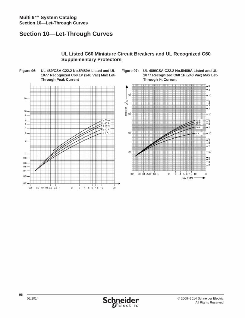
™
Multi 9™ System Catalog Section 10—Let-Through Curves
9602/2014 © 2008–2014 Schneider Electric
All Rights Reserved
Section 10—Let-Through Curves
UL Listed C60 Miniature Circuit Breakers and UL Recognized C60Supplementary Protectors
Figure 96: UL 489/CSA C22.2 No.5/489A Listed and UL 1077 Recognized C60 1P (240 Vac) Max Let-Through Peak Current
Figure 97: UL 489/CSA C22.2 No.5/489A Listed and UL 1077 Recognized C60 1P (240 Vac) Max Let-Through I2t Current
106
32
10
5432
10
5432
10
5432
10
5432
105
104
103
201087653210.2 0.80.60.50.40.3 4
A2 S
kA RMS
6 A
10 A25 A40 A63 A
0860
3207

™
Multi 9™ System CatalogSection 10—Let-Through Curves
9702/2014© 2008–2014 Schneider Electric
All Rights Reserved
Figure 98: UL 489/CSA C22.2 No.5 Listed and UL 1077 Recognized C60 2P, 3P, and 4P (240 Vac) Max Let-Through Peak Current
Figure 99: UL 489/CSA C22.2 No.5 Listed and UL 1077 Recognized C60 2P, 3P, and 4P (240 Vac) Max I2t Peak Current

™
Multi 9™ System Catalog Section 10—Let-Through Curves
9802/2014 © 2008–2014 Schneider Electric
All Rights Reserved
Figure 100: UL 489/CSA C22.2 No.5 Listed and UL 1077 Recognized C60 1P (277 Vac) Maximum Let-Through Peak Current
Figure 101: UL 489/CSA C22.2 No.5 Listed and UL 1077 Recognized C60 1P (277 Vac) Maximum I2tPeak Current
Figure 102: UL 1077 Recognized C60 2P, 3P, and 4P (480Y/277 Vac) Maximum Let-Through Peak Current
Figure 103: UL 1077 Recognized C60 2P, 3P, and 4P (480Y/277 Vac) Maximum Let-Through I²t Current

™
Multi 9™ System CatalogSection 10—Let-Through Curves
9902/2014© 2008–2014 Schneider Electric
All Rights Reserved
Figure 104: UL 1077 Recognized C60 2P, 3P, and 4P (480 Vac) Maximum Let-Through Peak Current
Figure 105: UL 1077 Recognized C60 2P, 3P, and 4P (480 Vac) Maximum Let-Through I²t Current
3210.2
0.2
0.3
0.4
0.5
0.6
0.8
1
2
3
4
56
8
10
20
0.3 0.4 0.5 0.6 0.8 4 5 6 7 8 10 20
kA RMS
Maximum Peak Current
6 A
10 A 20 A
kA08
6034
59
106
3
2
10
543
2
10
543
2
10
543
2
10
543
2
105
104
103
201087653210.2 0.80.60.50.40.3 4
A2 S
kA RMS
6 A
10 A20 A
0860
3460

™
Multi 9™ System Catalog Section 10—Let-Through Curves
10002/2014 © 2008–2014 Schneider Electric
All Rights Reserved
Limitation curves
For 230 V single-phase or 400 V three-phase network (TN or TT earthing system.
Table 91: Limitation Curves—C60N
1P / 3P / 4P Circuit Breakers
Peak Currents Thermal Stress
1P+N / 2P Circuit Breakers
Peak Currents Thermal Stress

™
Multi 9™ System CatalogSection 10—Let-Through Curves
10102/2014© 2008–2014 Schneider Electric
All Rights Reserved
Table 92: Limitation Curves—C60H
1P / 3P / 4P Circuit Breakers
Peak Currents Thermal Stress
1P+N / 2P Circuit Breakers
Peak Currents Thermal Stress

™
Multi 9™ System Catalog Section 10—Let-Through Curves
10202/2014 © 2008–2014 Schneider Electric
All Rights Reserved
Table 93: Limitation Curves—C60L
1P / 3P / 4P Circuit Breakers
Peak Currents Thermal Stress
1P+N / 2P Circuit Breakers
Peak Currents Thermal Stress

™
Multi 9™ System CatalogIndex
10302/2014 © 2008–2014 Schneider Electric
All Rights Reserved
Index of Part Numbers
Numerics13934 7113940 7113944 7113945 7113947 7113948 7113956 71, 8113957 71, 8113958 71, 8113959 71, 8113960 71, 8113962 71, 8213963 71, 8213964 71, 8213965 71, 8213966 7113967 71, 8213968 71, 8214210 6314211 6314881 5314882 5314886 5414891 5314893 5315005 6615006 6615007 6615008 6615009 6615010 6615102 6515103 6515129 6515440 6915443 6917400 5618030 6818031 6818032 6818033 6818034 6818035 6818036 6818037 6818038 6818039 6818320 67–6818321 6718322 6718323 6718324 6718325 6718326 6718330 6718333 6718334 6718335 6718401 34
18402 3418403 3418404 3418412 3418413 3418414 3418415 3418423 3418424 3418425 3418426 3418434 3418435 3418436 3418437 3418445 3418456 3418457 3418458 3418459 3418467 3418468 3418469 3418470 3418478 3418479 3418480 3418481 3418489 3418490 3418491 3418492 3418500 3418501 3418502 3418503 3418511 3418512 3418513 3418514 3418522 3418523 3418524 3418525 3418556 4218557 4218558 4218559 4218560 4218561 4218591 42–43, 4718592 4218593 4218594 4218595 4218596 4218597 4218598 4218599 4226345 3226346 32
26347 3226348 3226349 3226350 3226352 3226353 3226355 3226357 3226358 3226359 3226360 3226361 3226362 3226368 3226369 3226370 3226923 38, 4826924 4726927 4726970 5726975 5526976 5526978 5526981 55, 5926982 4126996 5927001 5527046 5727047 5727048 5727062 5427105 4727106 4727107 4727108 4727109 4727110 4727118 4727145 5727152 5960100 1860101 1860102 1860103 1860104 1860105 1860106 1860107 1860108 1860109 1860110 1860111 1860112 1860113 1860114 1860115 1860116 1860117 1860118 1860119 1860120 18
60121 1860122 1860123 1860124 1860125 1860126 1860127 1860128 1860129 1860130 1860131 1860132 1860133 1860134 1860135 1860136 1860137 1860138 1860139 1860140 1860141 1860142 1860143 1860144 1860145 1860146 1860147 1860148 1860149 1860150 1860151 1860152 1860153 1860154 1860155 1860156 1860157 1860158 1860159 1860160 1860161 1860162 1860163 1860164 1860165 1860166 1860167 1860168 1860169 1860170 1860171 1860172 1860173 1860174 1860175 1860176 1860177 1860178 1860179 1860180 1860181 18
60182 1860183 1860184 1860185 1860186 1860187 1860188 1860189 1860190 1860191 1860192 1860193 1860194 1860195 1860196 1860197 1860198 1860199 1860200 1860201 1860202 1860203 1860204 1860205 1860206 1860207 1860208 1860209 1860210 1860211 1860212 1860213 1860214 1860215 1860216 1860217 1860218 1860219 1860220 1860221 1860222 1860223 1860224 1860225 1860226 1860227 1860228 1860229 1860230 1860231 1860232 1860233 1860234 1860235 1860236 1860237 1860238 1860239 1860240 1860241 1860242 18

™
Multi 9™ System CatalogIndex
10402/2014© 2008–2014 Schneider Electric
All Rights Reserved
60243 1860244 1860245 1860246 1860247 1860248 1860249 1860250 1860251 1860252 1860253 1860254 1860255 1860256 1860257 1860258 1860259 1860260 1860261 1860262 1860263 1860264 1860265 1860266 1860267 1860268 1860269 1860270 1860271 1860272 1860273 1860274 1860275 1860276 1860277 1860278 1860279 1860280 1860281 1860282 1860283 1860284 1860285 1860286 1860287 1860288 1860289 1860290 1860291 1860292 1860293 1860294 1860295 1860296 1860297 1860298 1860299 1860488 5060949 3760950 3760951 3760952 3760954 3760955 37
60969 3760971 3760972 3760989 3760990 3760991 3760992 3760993 3760995 3760996 3760999 3783992 71, 8383993 71, 8383994 71, 8383995 71, 8383996 71, 8383997 71, 83
AAB1GA 56AB1GB 56AB1GC 56AB1GD 56AB1GE 56AB1GF 56AB1GG 56AB1GH 56AB1GI 56AB1GJ 56AB1GK 56AB1GL 56AB1GM 56AB1GN 56AB1GO 56AB1GP 56AB1GQ 56AB1GR 56AB1GS 56AB1GT 56AB1GU 56AB1GV 56AB1GW 56AB1GX 56AB1GY 56AB1GZ 56AB1R0 56AB1R1 56AB1R11 56AB1R12 56AB1R13 56AB1R2 56AB1R3 56AB1R4 56AB1R5 56AB1R6 56AB1R7 56AB1R8 56AB1R9 56AB1RV 56
CC125123 62C125183 62C125243 62
C325123 62C325183 62C325243 62C3DC123 62C3DC163 62C3DC203 62
MM9PAF 57M9PF4 63MG10285 50MG10286 50MG10287 50MG12279 23MG14885 54MG14892 53MG17402 23MG17403 23MG17404 23MG17405 23MG17406 23MG17407 23MG17408 23MG17409 23MG17411 23MG17412 23MG17413 23MG17414 23MG17415 23MG17416 23MG17417 23MG17418 23MG17419 23MG17421 23MG17422 23MG17423 23MG17424 23MG17425 23MG17426 23MG17427 23MG17428 23MG17429 23MG17432 23MG17433 23MG17434 23MG17435 23MG17436 23MG17437 23MG17438 23MG17439 23MG17442 23MG17443 23MG17444 23MG17445 23MG17446 23MG17447 23MG17448 23MG17449 23MG17452 23MG17453 23MG17454 23MG17455 23MG17456 23MG17457 23
MG17458 23MG17459 23MG17461 23MG17462 23MG17463 23MG17464 23MG17466 23MG17467 23MG17468 23MG17469 23MG17471 23MG17472 23MG17473 23MG17474 23MG24110 23MG24111 23MG24112 23MG24113 23MG24114 23MG24115 23MG24116 23MG24117 23MG24118 23MG24119 23MG24121 23MG24122 23MG24123 23MG24124 23MG24125 23MG24126 23MG24127 23MG24128 23MG24129 23MG24130 23MG24131 23MG24132 23MG24133 23MG24134 23MG24136 23MG24137 23MG24138 23MG24139 23MG24140 23MG24141 23MG24142 23MG24143 23MG24144 23MG24145 23MG24146 23MG24147 23MG24148 23MG24149 23MG24150 23MG24151 23MG24152 23MG24153 23MG24154 23MG24155 23MG24156 23MG24157 23MG24158 23MG24159 23MG24160 23MG24161 23
MG24162 23MG24163 23MG24164 23MG24165 23MG24166 23MG24167 23MG24168 23MG24169 23MG24425 23MG24426 23MG24427 23MG24428 23MG24430 23MG24431 23MG24432 23MG24433 23MG24434 23MG24435 23MG24436 23MG24437 23MG24438 23MG24439 23MG24440 23MG24442 23MG24443 23MG24444 23MG24445 23MG24447 23MG24448 23MG24449 23MG24450 23MG24451 23MG24452 23MG24453 23MG24454 23MG24455 23MG24456 23MG24457 23MG24459 23MG24460 23MG24461 23MG24462 23MG24464 23MG24465 23MG24466 23MG24467 23MG24468 23MG24469 23MG24470 23MG24471 23MG24472 23MG24473 23MG24474 23MG24476 23MG24477 23MG24478 23MG24481 23MG24482 23MG24483 23MG24484 23MG24485 23MG24486 23MG24487 23MG24488 23

™
Multi 9™ System CatalogIndex
10502/2014© 2008–2014 Schneider Electric
All Rights Reserved
MG24489 23MG24490 23MG24491 23MG24500 23MG24501 23MG24502 23MG24503 23MG24504 23MG24505 23MG24506 23MG24507 23MG24508 23MG24509 23MG24510 23MG24511 23MG24512 23MG24513 23MG24514 23MG24516 23MG24517 23MG24518 23MG24519 23MG24520 23MG24521 23MG24522 23MG24523 23MG24524 23MG24525 23MG24526 23MG24527 23MG24528 23MG24529 23MG24530 23MG24532 23MG24533 23MG24534 23MG24535 23MG24536 23MG24537 23MG24538 23MG24539 23MG24540 23MG24541 23MG24542 23MG24543 23MG24544 23MG24545 23MG24546 23MG24548 23MG24549 23MG24550 23MG24551 23MG24552 23MG24553 23MG24554 23MG24555 23MG24556 23MG24557 23MG24558 23MG24559 23MG24560 23MG24561 23MG24562 23MG26925 47
MG26928 47MG26970 57MG26975 55MG26976 55MG26978 55MG26983 59MG26984 59MG26985 59MG26986 59MG26987 59MG26988 59MG26989 59MG26990 59MG26996 59MG27001 55MG27046 57MG27047 57MG27048 57MG27062 54MG27124 60MG27145 57MGN61300 20MGN61301 20MGN61302 20MGN61303 20MGN61304 20MGN61305 20MGN61306 20MGN61307 20MGN61308 20MGN61309 20MGN61310 20MGN61311 20MGN61312 20MGN61313 20MGN61314 20MGN61315 20MGN61316 20MGN61317 20MGN61318 20MGN61319 20MGN61320 20MGN61321 20MGN61323 20MGN61324 20MGN61325 20MGN61326 20MGN61327 20MGN61328 20MGN61329 20MGN61330 20MGN61331 20MGN61332 20MGN61333 20MGN61334 20MGN61335 20MGN61336 20MGN61337 20MGN61338 20MGN61339 20MGN61340 20MGN613400 20MGN613401 20MGN613402 20
MGN613403 20MGN613404 20MGN613405 20MGN613406 20MGN613407 20MGN613408 20MGN613409 20MGN61341 20MGN613410 20MGN613411 20MGN613412 20MGN613413 20MGN613414 20MGN613415 20MGN613416 20MGN613417 20MGN613418 20MGN613419 20MGN61342 20MGN613420 20MGN613422 20MGN613423 20MGN613424 20MGN613425 20MGN613426 20MGN613427 20MGN613428 20MGN613429 20MGN61343 20MGN613430 20MGN613431 20MGN61344 20MGN61345 20MGN61346 20MGN61347 20MGN61348 20MGN61349 20MGN61350 20MGN61351 20MGN61352 20MGN61353 20MGN61354 20MGN61356 20MGN61357 20MGN61358 20MGN61359 20MGN61360 20MGN61361 20MGN61362 20MGN61363 20MGN61364 20MGN61365 20MGN61366 20MGN61367 20MGN61368 20MGN61369 20MGN61370 20MGN61371 20MGN61372 20MGN61373 20MGN61374 20MGN61375 20MGN61376 20MGN61377 20
MGN61378 20MGN61379 20MGN61380 20MGN61381 20MGN61382 20MGN61383 20MGN61384 20MGN61385 20MGN61386 20MGN61387 20MGN61389 20MGN61390 20MGN61391 20MGN61392 20MGN61393 20MGN61394 20MGN61395 20MGN61396 20MGN61397 20MGN61398 20MGN61399 20
UUS11220018 60US12420018 60US13620018 60US14820018 60US16020018 60US21215018 60US22420018 60US23620018 60US24820018 60US26020018 60US31220018 60US32420018 60US33620018 60US34820018 60US36020018 60

Schneider Electric USA, Inc.1415 S. Roselle RoadPalatine, IL 60067 USA1-888-778-2733www.us.SquareD.com
Schneider Electric Canada, Inc.5985 McLaughlin RoadMississauga, ON L5R 1B8 CanadaTel:1-800-565-6699www.schneider-electric.ca
02/2014
© 2008–2014 Schneider Electric All Rights ReservedSchneider Electric, Square D, and Multi 9 are trademarks owned by Schneider Electric Industries SAS or its affiliated companies. All other trademarks are the property of their respective owners.
0860CT0201 R02/14