Embed Size (px)
Citation preview
Standard Article
Concurrent Engineering: Researchand Applications1–15� The Author(s) 2017Reprints and permissions:sagepub.co.uk/journalsPermissions.navDOI: 10.1177/1063293X17708820journals.sagepub.com/home/cer
Multi-variation propagation predictionbased on multi-agent system forcomplex mechanical product design
Songhua Ma, Zhaoliang Jiang and Wenping Liu
AbstractThe design change propagation in a complex product is characteristic of nonlinear, dynamic, and uncertain; its impactanalysis becomes challenging. Furthermore, the multiple changes occurring concurrently during the whole design processincrease the difficulty of the change propagation analysis. In this article, a new change propagation prediction methodbased on multi-agent system, especially for multi-variations, is proposed to improve the validity of the change routingpaths. As the foundation of the proposed prediction method, a hierarchical network composited of the specific designproperties is used to represent the design change analysis model. Based on the discussion of concurrent propagationpatterns in the context of multi-variations, the quantitative definition of change propagation impact focuses on two fac-tors: change impact and propagation likelihood. To reduce the subjective measurements estimated through the designer’sexperience, the change impact and the propagation likelihood are quantified by evaluating the design specification andmining the design change records, respectively. Based on the quantified change propagation impact, the multi-variationpropagation simulation is parameterized and implemented in the platform of NetLogo. To demonstrate the effectivenessof the proposed method, experiments are conducted with one typical scenario. Compared with the classical change pro-pagation methods, the proposed method proves to be valid for analyzing the concurrent change propagation, and theanalysis reliability is guaranteed.
Keywordsmulti-variation propagation, design change analysis model, multi-agent system, concurrent propagation, change propaga-tion prediction
Introduction
The development of a new mechanical product can beinterrupted by a wide range of design changes from thedesign requirements, technological innovation, politicalenvironments, and so on. With very different causes,design changes can be classified into two main cate-gories: emergent design change and initiated designchange. The former is caused by the problems occurringacross the internal design project due to solution uncer-tainty, whereas the latter is caused from external stake-holders such as new customer requirements,technological innovations, and regulation modifications(Eckert et al., 2004). All these changes have a signifi-cant impact on the outcome of product development.According to the statistics, the design changes deter-mine as much as 70%–80% of the final cost of a prod-uct (McIntosh, 1995) and bring uncertainties to the
development schedule and quality. By analyzing thechange records of certain original equipment manufac-turers, Shankar et al. (2012) found that 77.0% ofchanges were derived from internal reasons, while23.0% were external and inferred that 32.4% of thetotal changes resulted from the change propagation.
Change propagation is a process in which a changeto one element of an existing design tends to triggeradditional changes to other elements of the same design
Key Laboratory of High Efficiency and Clean Mechanical Manufacture,
Ministry of Education, Shandong University, Jinan, P.R. China
Corresponding author:
Songhua Ma, Key Laboratory of High Efficiency and Clean Mechanical
Manufacture, Ministry of Education, Shandong University, Jinan 250100,
P.R. China.
Email: [email protected]
in a cause-effect-cause-effect pattern. This propagationwill not be completed until the design achieves a newstable status. In other words, such loop-like, dynamic,and recursive change propagation processes continueuntil all of the inconsistencies are identified.Consequently, it is even possible for changes that wereinitially thought as simple to propagate uncontrollably,resulting in an avalanche propagation. This is especiallytrue for the design of complex products composed oftightly coupled elements and functionalities.Considering the fact that certain design properties aretightly coupled and numerous branches should be rou-ted, the change propagation prediction can becomemore challenging even if the product under designundergoes minor changes. Numerous random or uncer-tain changes that often conflict with each other mayoccur in a design process and increase the risk of prod-uct development. Therefore, it is significant to predictthe change propagation and route the change to satisfythe design requirement with low cost. Predicting theimpact of the changes helps the design reviewers iden-tify and evaluate the effects of the change.
Multi-variations are short for the multiple changesbeing concurrently triggered on different elements orsystems in the complex mechanical product design.During the concurrent propagation processes, theyoften reduce or amplify each other at the couplednode. Some changes may increase the value of thecoupled node, whereas the others may decrease it.This kind of change conflict is common during theconcurrent design process and even causes repetitiveredesign work. Thus, it is urgent to propose a tech-nique to predict how multi-variations affect the rest ofproduct and to evaluate which nodes need to be modi-fied accordingly.
To assess the impact caused by the multi-variations,a change propagation prediction approach based onthe multi-agent technology is proposed for the complexmechanical product design. The design properties andthe specifications of the development process can berepresented with a hierarchical network model, and thesystem-level impact resulting from the multi-variationscan be assessed quantitatively.
Related work
Engineering change research can be traced back to theearly 1980s when the first publication was contributedby Diprima (1982). Due to the limitations of less-advanced technologies, previous research focused onthe consistency of information during changing. Thissection introduces the state-of-the-art change propaga-tion prediction approaches from two aspects: analysismodel and prediction method.
Design change analysis model
The design attributes, functions, and requirements canall be represented as components connected via inter-component links in the design change analysis model(DCAM). Prasad (2002) defined four kinds of designvariables that would be subject to change including sizevariable, shape variable, topology variable, and processvariable to capture a system-level optimization as partof a product design process. The most famous study onDCAM is the contribution from Clarkson et al. (2004),who built a design structure matrix (DSM) as DCAM,according to the parameter relationships of the designcomponents. Some later studies modified the DSM toexclude the propagation loop path and self-dependentpath (Hamraz et al., 2013a) and to analyze the require-ment change propagation (Morkos et al., 2012). Basedon the DSM, Li and Chen (2014) utilized a designdependency matrix (DDM) to organize the dependen-cies between design parameters and functions. Exceptfor DSM, Cohen et al. (2000) proposed a C-FAR(Change Favorable Representation) matrix to describethe product in the form of attribute/value to analyzethe change impact. Based on the house of quality(HoQ), Koh et al. (2012) modeled the effects of thepotential change propagation generated by productcomponents, change options, and product require-ments. After the function-behavior-structure (FBS)ontology was proposed by Gero (1990), its modifica-tions were introduced for modeling DCAM (Ahmad etal., 2013; Fei et al., 2011). As an extension of FBS,Pasqual and De Weck (2012) introduced a multilayernetwork model including three coupled layers, that is,product layer, change layer, and social layer.
To simulate the change impact, the design activitiesor tasks were often defined as the components of theDCAM in several studies. In particular, the dependen-cies of design activities were represented as DSM toevaluate the change impact in Chua and Hossain’swork (Chua and Hossain, 2012). Seeing works fromWynn et al. (2014) and Li et al. (2012), the design taskswere modeled as the nodes of a complex design work-flow to predict change propagation and to select themost economic propagation path. Li and Moon (2012)organized the design activities as a process to investi-gate how the requirements and technology changeseventually affect the leading time, cost, and quality.
Recently, the network-based DCAM has attractedthe attention of researchers. Cheng and Chu (2012)considered the complex product as a weighted networkcomposed of parts, subassemblies, and subsystems. Toanalyze the variation propagation of the quality char-acteristic (QC), Duan and Wang (2013) built a QC-linkage network, which was constructed by the designproperties, parameter relationships, and constraint
2 Concurrent Engineering: Research and Applications
relationships. Lee et al. (2010) introduced the analyticnetwork process (ANP)-based approach to measure therelative weight of parts and modules in a modularproduct in terms of design change impacts. Reddi andMoon (2011) developed a dynamic system model for acollaborative supply chain to study effective and effi-cient engineering change management.
Change propagation prediction method
At the macro level, the effects of change propagate inthree patterns: (1) ripple, which triggers a small andfast-decreasing volume of changes; (2) blossom—a largenumber of changes which oscillate and turn to be con-vergent within expected limits; and (3) avalanche—anincreasing volume of changes that may not be broughtto a conclusion after a given end point (within a certaintime or number of changes). The quantification of themeasurements is essential to the validity of the changepropagation prediction. In previous research, designexperts were responsible for estimating the measure-ments of the change propagation effort, such as propa-gation likelihood and change impact in most DSM-based research (Clarkson et al., 2004). However, themeasurements extracted from the existing changerecords and the characteristics of DCAM are moreobjective. Duan and Wang (2013) adopted several var-iation mitigation methods to reduce the change impact,such as source uncoupling, variation compensation,variation deployment, linkage sensitiveness, linkageprinciple, superposing effect variation, and propagationpath variation. Ouertani (2008) evaluated the changeuncertainty conditions using the variability, sensitivity,and completeness of the nodes in a data dependencynetwork. Mehta et al. (2013) quantified the importantattribute sets by the information entropy to capture theknowledge from the existing engineering changes. Tanget al. (2016) found the optimal solution of the designchange propagation by examining the workload of eachchange propagation path.
The change propagation impact can be simply evalu-ated by k copies of the adjacency matrix extracted fromDCAM, where k corresponds to the number of walksfrom the initial changed element to the others.However, searching change propagation path can beabstracted into a traveling salesman problem known tobe NP-hard (non-deterministic polynomial-time hard).Yang and Duan (2012) filtered the optimal change pro-pagation paths based on certain selection strategies. Liand Zhao (2014) applied the genetic algorithm to findthe optimal propagation likelihood for each optionalpropagation path. Furthermore, they modified thebreadth-first search method to locate the shortest pathsof change propagation (Li et al., 2016). Ni Li et al.
(2015) utilized multi-agent systems (MASs) to assessthe risk propagation for complex product design.
Current issues
Most of the previous research works modeled the prod-uct as a network of elements (i.e. systems, components,or parts) that were linked by their dependencies (i.e.structural, behavioral, and functional parameters) toconstruct an available DCAM and further describedthe change propagation as the spread of knock-oneffects along the links of this network. Although theprevious methods are helpful tools in analyzing changepropagation, there are three primary issues that preventthe current change propagation prediction methodbeing applied:
1. In most of the previous research works, each com-ponent in DCAM corresponds to a design part ora subsystem (Clarkson et al., 2004). The roughorganization prevents the valid impact assessment.One reason for this may be due to the subjectivemeasurements evaluated from the design experi-ence, which often deviate from the actual values.In this case, it is important to propose a quantita-tive metric and an objective measuring method.Building the DCAM at the property/parameterlevel would help assess the impact of change pro-pagation objectively and quantitatively. Obviously,the change prefers the path with the larger propa-gation likelihood and the lower change impact topropagate to guarantee that the change propaga-tion converges rapidly.
2. Chua and Hossain (2012) found that five factors—the transition matrix, degree of initiated change,timing of initiated change, point of initiatedchange, and redesign duration—affect the changepropagation. The previous research neglected todistinguish the different change propagationimpacts resulting from the different volumes of theinitiated change. Consequently, even if the volumeof initiated change varies, the results from the pre-vious prediction method remain the same since theDCAM and the initial change unvaried. It is essen-tial to predict the change propagation paths thatcan vary with the variation of the initiated changes.
3. In complex product design, in particular, severalchanges may be triggered on different elements orsystems at the same time, which often interact witheach other. It is necessary to negotiate about thevolume of variation to resolve the conflict frommulti-variations. Furthermore, multi-variationswould generate the propagation loop sometimesand cause repeated redesign work that is unfavor-able in the design process. The propagation loop
Ma et al. 3
should be predicted and resolved before the changebeing implemented. The previous research focuseson studying the propagation impact deliveringfrom a sole initiated change (Yang and Duan,2012). However, the multi-variations occurring andpropagating concurrently in the complex designprocesses are more complicated to analyze, whichare the causes for concern.
Change propagation foundation—DCAM
Design changes are changes and/or modifications tothe released structure (fits, forms and dimensions, sur-faces, materials, etc.), behavior (stability, strength, cor-rosion, etc.), function (speed, performance, efficiency,etc.), or the relations between function and behavior(design principles), or behavior and structure (physicallaws) of a technical artifact (Hamraz et al., 2013b). Thestructural attributes, behavioral attributes, and func-tional attributes are unified as design property. Thisarticle focuses on analyzing the change impact resultingfrom the variations of some design properties. In otherwords, the parameter value of some design propertiesvaries with the change propagation, while the relationsbetween design properties and the topology of theDCAM remain the same.
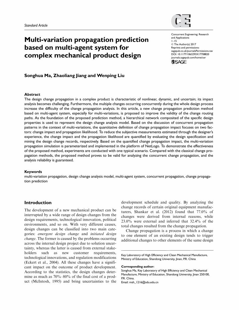
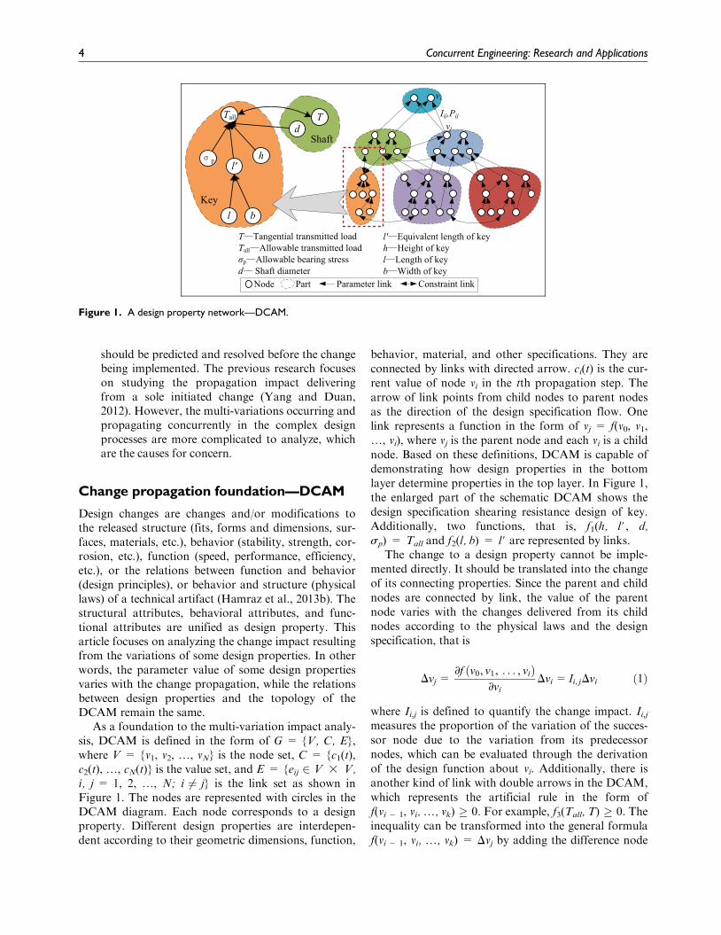
As a foundation to the multi-variation impact analy-sis, DCAM is defined in the form of G = {V, C, E},where V = {v1, v2, ., vN} is the node set, C = {c1(t),c2(t), ., cN(t)} is the value set, and E = {eij 2 V 3 V,i, j = 1, 2, ., N; i 6¼ j} is the link set as shown inFigure 1. The nodes are represented with circles in theDCAM diagram. Each node corresponds to a designproperty. Different design properties are interdepen-dent according to their geometric dimensions, function,
behavior, material, and other specifications. They areconnected by links with directed arrow. ci(t) is the cur-rent value of node vi in the tth propagation step. Thearrow of link points from child nodes to parent nodesas the direction of the design specification flow. Onelink represents a function in the form of vj = f(v0, v1,., vi), where vj is the parent node and each vi is a childnode. Based on these definitions, DCAM is capable ofdemonstrating how design properties in the bottomlayer determine properties in the top layer. In Figure 1,the enlarged part of the schematic DCAM shows thedesign specification shearing resistance design of key.Additionally, two functions, that is, f1(h, l#, d,sp) = Tall and f2(l, b) = l# are represented by links.
The change to a design property cannot be imple-mented directly. It should be translated into the changeof its connecting properties. Since the parent and childnodes are connected by link, the value of the parentnode varies with the changes delivered from its childnodes according to the physical laws and the designspecification, that is
Dvj =∂f v0, v1, . . . , við Þ
∂vi
Dvi = Ii, jDvi ð1Þ
where Ii,j is defined to quantify the change impact. Ii,jmeasures the proportion of the variation of the succes-sor node due to the variation from its predecessornodes, which can be evaluated through the derivationof the design function about vi. Additionally, there isanother kind of link with double arrows in the DCAM,which represents the artificial rule in the form off(vi 2 1, vi, ., vk) � 0. For example, f3(Tall, T) � 0. Theinequality can be transformed into the general formulaf(vi 2 1, vi, ., vk) = Dvj by adding the difference node
Figure 1. A design property network—DCAM.
4 Concurrent Engineering: Research and Applications
Dvj as referring to Yang and Duan’s (2012) work. Afterrecursively defining nodes and searching for their childnodes, the DCAM is then constructed as a complex net-work composed of nodes and links. Consequently, theDCAM shows how the design properties in the bottomlayer determine others in the top layer.
A design property can be both the child node in onelink and the parent node in another, such as the prop-erty l# in the aforementioned example. The nodes con-nected with only their parent nodes or child nodesform the boundary of DCAM. After an initial changeis triggered, its propagation continues until reachingthe boundary nodes. The variation from the lower layernode can propagate upward to the upper layer nodesand even cause the impact diffusion. Conversely, theupper layer variation should be decomposed and trans-mitted to its child nodes, until the boundary nodes arefixed.
Change propagation pattern
Based on the constructed DCAM, the changes of somedesign properties can propagate along the links. Toevaluate the variations of the impacted nodes, thechange propagation pattern in the DCAM is concludedin this section, which can be categorized into three: sin-gle, multiple, and loop-like.
Sole change propagation pattern
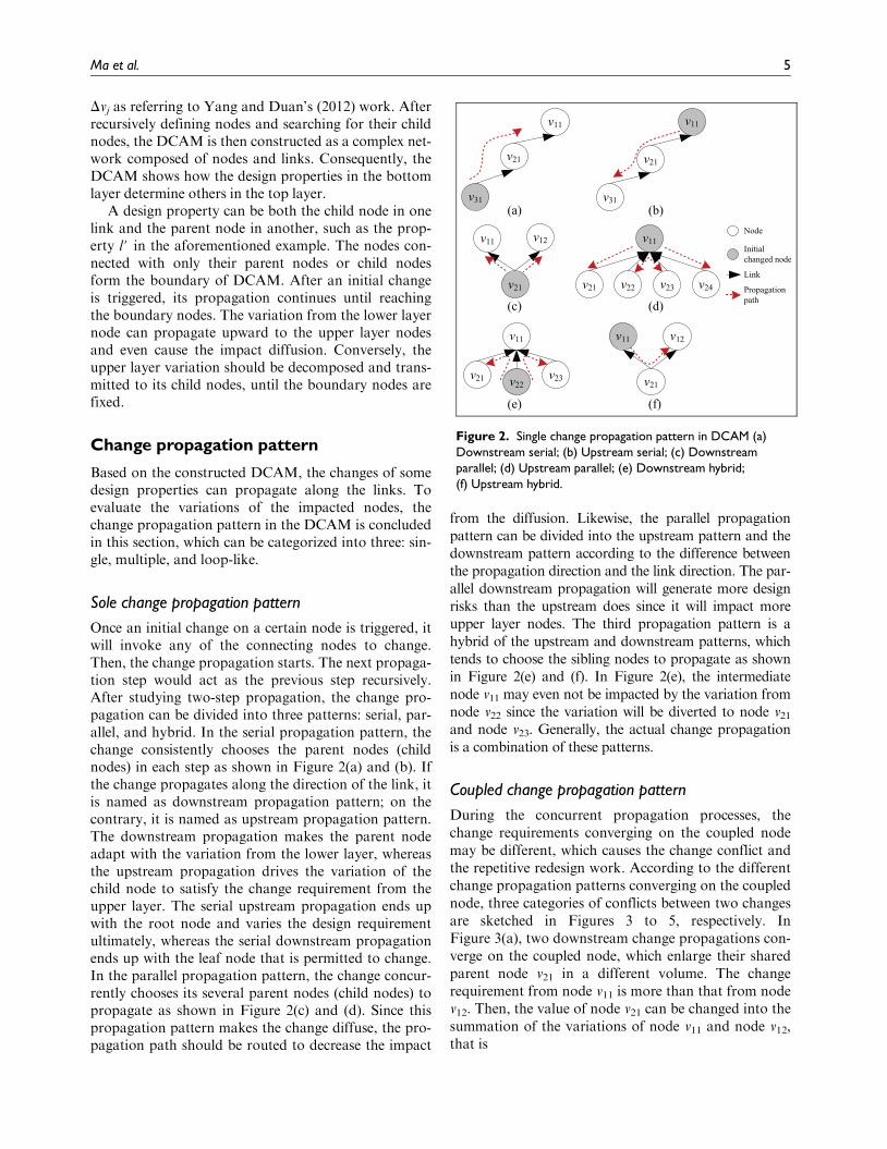
Once an initial change on a certain node is triggered, itwill invoke any of the connecting nodes to change.Then, the change propagation starts. The next propaga-tion step would act as the previous step recursively.After studying two-step propagation, the change pro-pagation can be divided into three patterns: serial, par-allel, and hybrid. In the serial propagation pattern, thechange consistently chooses the parent nodes (childnodes) in each step as shown in Figure 2(a) and (b). Ifthe change propagates along the direction of the link, itis named as downstream propagation pattern; on thecontrary, it is named as upstream propagation pattern.The downstream propagation makes the parent nodeadapt with the variation from the lower layer, whereasthe upstream propagation drives the variation of thechild node to satisfy the change requirement from theupper layer. The serial upstream propagation ends upwith the root node and varies the design requirementultimately, whereas the serial downstream propagationends up with the leaf node that is permitted to change.In the parallel propagation pattern, the change concur-rently chooses its several parent nodes (child nodes) topropagate as shown in Figure 2(c) and (d). Since thispropagation pattern makes the change diffuse, the pro-pagation path should be routed to decrease the impact
from the diffusion. Likewise, the parallel propagationpattern can be divided into the upstream pattern and thedownstream pattern according to the difference betweenthe propagation direction and the link direction. The par-allel downstream propagation will generate more designrisks than the upstream does since it will impact moreupper layer nodes. The third propagation pattern is ahybrid of the upstream and downstream patterns, whichtends to choose the sibling nodes to propagate as shownin Figure 2(e) and (f). In Figure 2(e), the intermediatenode v11 may even not be impacted by the variation fromnode v22 since the variation will be diverted to node v21and node v23. Generally, the actual change propagationis a combination of these patterns.
Coupled change propagation pattern
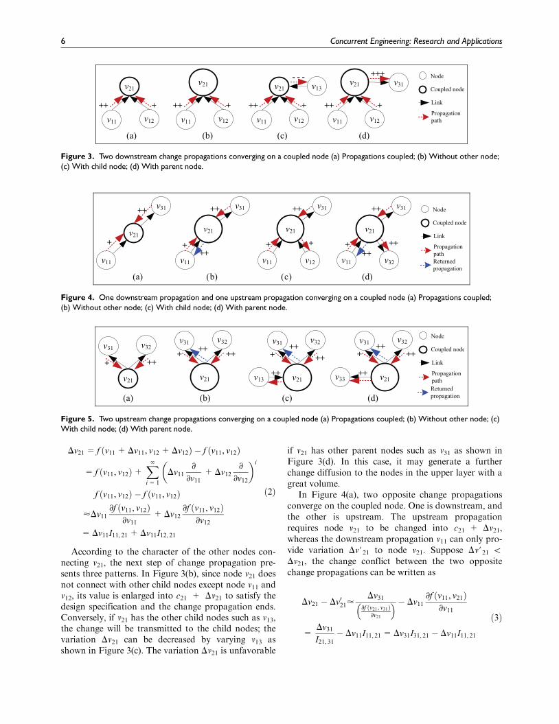
During the concurrent propagation processes, thechange requirements converging on the coupled nodemay be different, which causes the change conflict andthe repetitive redesign work. According to the differentchange propagation patterns converging on the couplednode, three categories of conflicts between two changesare sketched in Figures 3 to 5, respectively. InFigure 3(a), two downstream change propagations con-verge on the coupled node, which enlarge their sharedparent node v21 in a different volume. The changerequirement from node v11 is more than that from nodev12. Then, the value of node v21 can be changed into thesummation of the variations of node v11 and node v12,that is
Figure 2. Single change propagation pattern in DCAM (a)Downstream serial; (b) Upstream serial; (c) Downstreamparallel; (d) Upstream parallel; (e) Downstream hybrid;(f) Upstream hybrid.
Ma et al. 5
Dv21 = f v11 +Dv11, v12 +Dv12ð Þ � f v11, v12ð Þ
= f v11, v12ð Þ+X‘
i= 1
Dv11
∂
∂v11
+Dv12
∂
∂v12
� �i
f v11, v12ð Þ � f v11, v12ð Þ
’Dv11
∂f v11, v12ð Þ∂v11
+Dv12
∂f v11, v12ð Þ∂v12
=Dv11I11, 21 +Dv11I12, 21
ð2Þ
According to the character of the other nodes con-necting v21, the next step of change propagation pre-sents three patterns. In Figure 3(b), since node v21 doesnot connect with other child nodes except node v11 andv12, its value is enlarged into c21 + Dv21 to satisfy thedesign specification and the change propagation ends.Conversely, if v21 has the other child nodes such as v13,the change will be transmitted to the child nodes; thevariation Dv21 can be decreased by varying v13 asshown in Figure 3(c). The variation Dv21 is unfavorable
if v21 has other parent nodes such as v31 as shown inFigure 3(d). In this case, it may generate a furtherchange diffusion to the nodes in the upper layer with agreat volume.
In Figure 4(a), two opposite change propagationsconverge on the coupled node. One is downstream, andthe other is upstream. The upstream propagationrequires node v21 to be changed into c21 + Dv21,whereas the downstream propagation v11 can only pro-vide variation Dv#21 to node v21. Suppose Dv#21 \Dv21, the change conflict between the two oppositechange propagations can be written as
Dv21 � Dv021’Dv31
∂f v21, v31ð Þ∂v21
� �� Dv11
∂f v11, v21ð Þ∂v11
=Dv31
I21, 31
� Dv11I11, 21 =Dv31I31, 21 � Dv11I11, 21
ð3Þ
Figure 3. Two downstream change propagations converging on a coupled node (a) Propagations coupled; (b) Without other node;(c) With child node; (d) With parent node.
Figure 4. One downstream propagation and one upstream propagation converging on a coupled node (a) Propagations coupled;(b) Without other node; (c) With child node; (d) With parent node.
Figure 5. Two upstream change propagations converging on a coupled node (a) Propagations coupled; (b) Without other node; (c)With child node; (d) With parent node.
6 Concurrent Engineering: Research and Applications
To prevent further change diffusion to the upper layernodes, node v21 is enlarged into Dv21 as the change require-ment from node v31. Furthermore, the variation of v21returns to node v11 to form a new upstream propagationaccording to the design specification as indicated by theblue arrow in Figure 4(b). In Figure 4(c), since node v21has another child node v12 besides v11, the conflicting var-iation Dv21 2 Dv#21 can be routed to node v12 to satisfythe change requirements from both v11 and v31 at the sametime. If v21 has another parent node v32, its variation Dv21will certainly diffuse to v32 as shown in Figure 4(d).
In Figure 5(a), two upstream change propagationsconverge on a coupled node. The change requirementsfrom parent node v31 and node v32 are different, wheresuppose Dv21 \ Dv#21. The change conflict betweenDv21 and Dv#21 can be expressed as
Dv021 � Dv21’Dv32
∂f v21, v32ð Þ∂f v21ð Þ
� Dv31
∂f v21, v31ð Þ∂f v21ð Þ
=Dv32
I21, 32
� Dv31
I21, 31
=Dv32I32, 21 � Dv31I31, 21
ð4Þ
Suppose that node v21 is enlarged with Dv#21 as thechange requirement from v32, node v31 varies according tothe variation of v21 to form a new downstream propaga-tion as indicated by the blue arrow in Figure 5(b). Thisdownstream propagation can never be routed no matterwhether node v21 has another child node as shown inFigure 5(c) or other parent nodes as shown in Figure 5(d).
In fact, the variation could be positive or negative.All the examples use the positive variation to illustratethe change propagation pattern, which does not impactthe conclusion. If the multiple changes converge on thecoupled node, which can be analyzed as the aforemen-tioned examples, the conclusion remains the same. Tothe couple node vi, its variation is determined by sum-ming the variation of its neighboring node vj as theaforementioned analysis. The temporal value of vi atthe next propagation step t + 1 can be calculated asthe summation of all the variations from the neighbor-ing nodes at the current step t as follows
ci(t + 1)= ci(t)+max
Xj2Fchild
i
cj(t)� cj(t � 1)� �
Ij, i, maxj2Fparenti
cj(t)� cj(t � 1)� �
Ij, i
� �0@
1A
ð5Þ
where Fchildi is the set of child nodes of vi, and F
parenti is
the set of parent nodes of vi.
Loop-like change propagation
It is common to confront different change requirementsduring the complex mechanical product design. One
needs the couple node changed into the variation Dciand the other only requires Dc#i (Dci 6¼ Dc#i). This kindof conflict between multiple change requirementsshould be resolved by planning the change propagationpath. Furthermore, if the conflicting changes propagatealong a closed-loop path, which would never be elimi-nated, they cause the loop-like propagation and therepetitive change. To avoid the loop-like propagationand repetitive changes, the conflicting change require-ments on the closed-loop path should make some nego-tiations about the variations before being implemented.Consequently, the change requirements are not equalto the initial after the trade-off negotiations.
During the negotiation process, the change require-ment of node vi is impacted by that of its neighboringnodes which belong to the closed-loop path, that is
Dci(t + 1)= Ij, iDcj(t) ð6Þ
where t represents the negotiation step that differs fromthe definition of propagation step t. In general, theabove function can be transformed into matrix form as
DC(t + 1)= IDC(t) ð7Þ
where I is the impact matrix. The solution is directlydetermined by the eigenvalues of I. Consequently, thestable change requirements after the negotiation aredetermined by the eigenvalues of I. Then, the eigenva-lues of I can be utilized to analyze the ability of agree-ment. The necessary (but not sufficient) condition ofreaching the agreement is s(I) \ 1, where s is themaximum non-trivial eigenvalue of I or named spectralgap. If s(I) \ 1, the conflicts between the changerequirements of the related nodes would decrease expo-nentially. The negotiation terminates until the changerequirements from all the neighboring nodes do notvary.
Generally, it is not common to satisfy the conditions(I) \ 1 to the nodes on the closed-loop path. Takinga closed-loop path containing three nodes, for example,suppose the initial change requirements of the nodesare 0.5, 1.0, and 0.25, respectively, that is, Dc0(0) =0.5, Dc1(0) = 1.0, and Dc2(0) = 0.25 as shown inFigure 6(a). The change impact between each other canbe found in the diagram. In this case, the negotiationof the change requirements can reach an agreement,although s(I) = 1. If Dc2(0) is changed into 20.25 asshown in Figure 6(b), the change requirements of threenodes disagree with each other at the initial negotiationstep. Then, the change requirements oscillate on theclosed-loop path according to equation (6). In this case,the change conflicts cannot be resolved by the negotia-tion unless the change requirements jump out of theclosed-loop path and search for another propagationpath. In Figure 6(c), the impact matrix is changed, and
Ma et al. 7
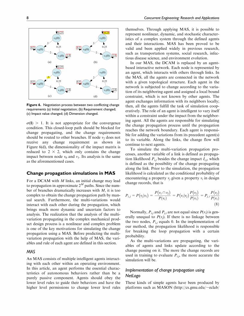
s(I) . 1. It is not appropriate for the convergencecondition. This closed-loop path should be blocked forchange propagating, and the change requirementsshould be routed to other branches. If node v2 does notreceive any change requirement as shown inFigure 6(d), the dimensionality of the impact matrix isreduced to 2 3 2, which only contains the changeimpact between node v0 and v1. Its analysis is the sameas the aforementioned cases.
Change propagation simulations in MAS
For a DCAM with M links, an initial change may leadto propagation in approximate 2M paths. Since the num-ber of branches dramatically increases with M, it is toocomplex to obtain the change propagation path by man-ual search. Furthermore, the multi-variations wouldinteract with each other during the propagation, whichbrings much more dynamic and uncertain factors toanalysis. The realization that the analysis of the multi-variation propagating in the complex mechanical prod-uct design process is a nonlinear and complex problemis one of the key motivations for simulating the changepropagation using a MAS. Before predicting the multi-variation propagation with the help of MAS, the vari-ables and rule of each agent are defined in this section.
MAS
An MAS consists of multiple intelligent agents interact-ing with each other within an operating environment.In this article, an agent performs the essential charac-teristics of autonomous behaviors rather than be apurely passive component. Agents should obey thelower level rules to guide their behaviors and have thehigher level permissions to change lower level rules
themselves. Through applying MAS, it is possible torepresent nonlinear, dynamic, and stochastic character-istics of a complex system through the defined agentsand their interactions. MAS has been proved to bevalid and been applied widely in previous research,such as transportation systems, social research, infec-tious disease science, and environment evolution.
In our MAS, the DCAM is replaced by an agent-based interactive network. Each node is represented byan agent, which interacts with others through links. Inthe MAS, all the agents are connected in the networkwith a given topological structure. Each agent in thenetwork is subjected to change according to the varia-tion of its neighboring agent and assigned a local boundconstraint, which is not known by other agents. Theagent exchanges information with its neighbors locally;then, all the agents fulfill the task of simulation coop-eratively. The role of an agent is intelligent to vary itselfwithin a constraint under the impact from the neighbor-ing agent. All the agents are responsible for simulatingthe change propagation process until the propagationreaches the network boundary. Each agent is responsi-ble for adding the variations from its precedent agent(s)to its variable. Along the links, the change flow willcontinue to next agents.
To simulate the multi-variation propagation pro-cesses, another variable of a link is defined as propaga-tion likelihood Pi,j besides the change impact Ii,j, whichis defined as the possibility of the change propagatingalong the link. Prior to the simulation, the propagationlikelihood is calculated as the conditional probability ofencountering a property vj given a property vi in designchange records, that is
Pi, j =P vjjvi
� �=
P vi \ vj
� �P við Þ
=P vijvj
� �P vj
� �P við Þ
=Pj, i
P vj
� �P við Þð8Þ
Normally, Pi,j and Pj,i are not equal since P(vi) is gen-erally unequal to P(vj). If there is no linkage betweenthe two nodes, Pi,j equals 0. In the implementation ofour method, the propagation likelihood is responsiblefor breaking the loop propagation with a certainprobability.
As the multi-variations are propagating, the vari-ables of agents and links update according to thechange passing on it. The more the change records areused in training to evaluate Pi,j, the more accurate thesimulation will be.
Implementation of change propagation usingNetLogo
These kinds of simple agents have been produced byplatforms such as MASON (http://cs.gmu.edu/;eclab/
Figure 6. Negotiation process between two conflicting changerequirements (a) Initial negotiation; (b) Requirement changed;(c) Impact value changed; (d) Dimension changed.
8 Concurrent Engineering: Research and Applications
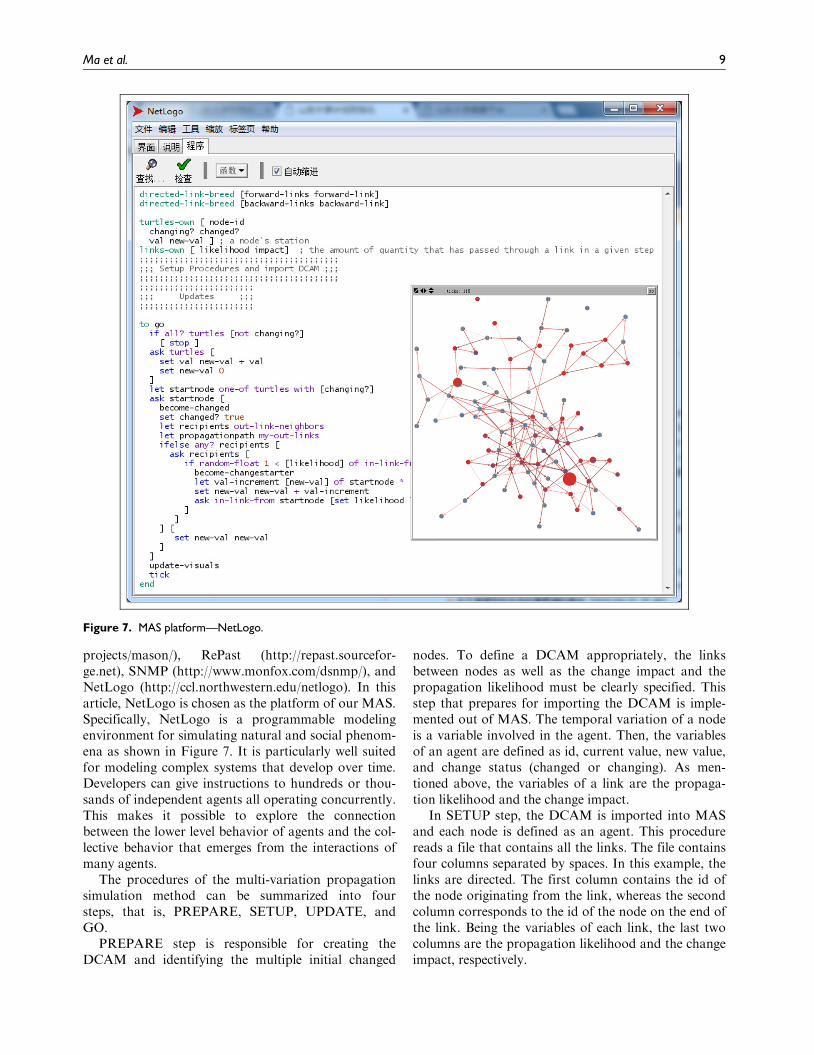
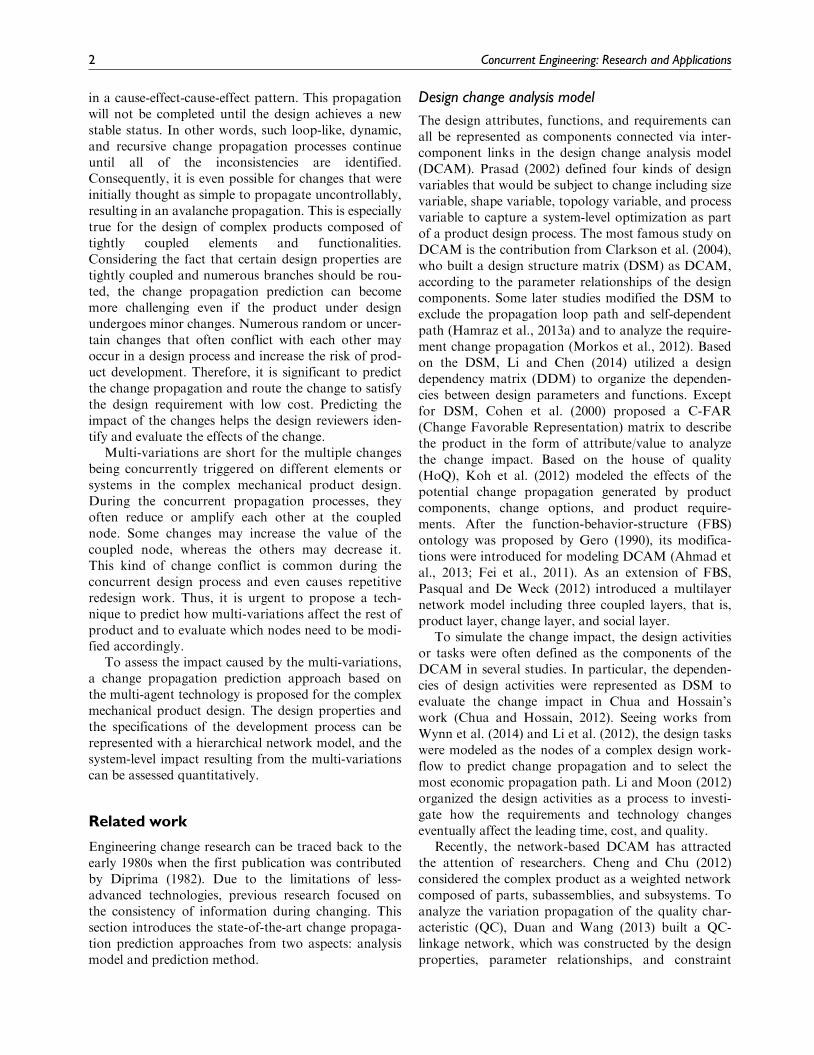
projects/mason/), RePast (http://repast.sourcefor-ge.net), SNMP (http://www.monfox.com/dsnmp/), andNetLogo (http://ccl.northwestern.edu/netlogo). In thisarticle, NetLogo is chosen as the platform of our MAS.Specifically, NetLogo is a programmable modelingenvironment for simulating natural and social phenom-ena as shown in Figure 7. It is particularly well suitedfor modeling complex systems that develop over time.Developers can give instructions to hundreds or thou-sands of independent agents all operating concurrently.This makes it possible to explore the connectionbetween the lower level behavior of agents and the col-lective behavior that emerges from the interactions ofmany agents.
The procedures of the multi-variation propagationsimulation method can be summarized into foursteps, that is, PREPARE, SETUP, UPDATE, andGO.
PREPARE step is responsible for creating theDCAM and identifying the multiple initial changed
nodes. To define a DCAM appropriately, the linksbetween nodes as well as the change impact and thepropagation likelihood must be clearly specified. Thisstep that prepares for importing the DCAM is imple-mented out of MAS. The temporal variation of a nodeis a variable involved in the agent. Then, the variablesof an agent are defined as id, current value, new value,and change status (changed or changing). As men-tioned above, the variables of a link are the propaga-tion likelihood and the change impact.
In SETUP step, the DCAM is imported into MASand each node is defined as an agent. This procedurereads a file that contains all the links. The file containsfour columns separated by spaces. In this example, thelinks are directed. The first column contains the id ofthe node originating from the link, whereas the secondcolumn corresponds to the id of the node on the end ofthe link. Being the variables of each link, the last twocolumns are the propagation likelihood and the changeimpact, respectively.
Figure 7. MAS platform—NetLogo.
Ma et al. 9
After the DCAM is imported, the network shouldbe layout. The UPDATE step is called to update theappearance of nodes and links. To help the usersobserve the variable of each agent, the size of nodes isscaled as its value is changed and the color of the linkis brightened when the variation flows through it.
GO step, which is responsible for defining the rule ofagents, is the main part of the simulation method. If thechange conflict occurs in the propagation loop, it couldbe possible to jump out of the loop with the definedpropagation likelihood. The value of each agent varieswith the variation of the connecting agents according tothe following equation
cj(t + 1)= cj(t) Prad . Pi, j
cj(t + 1)= cj(t)+ ci(t + 1)� ci(t)ð ÞIi, j Prad � Pi, j
�, i 2 Fj
ð9Þ
Searching the change propagation paths will not stopuntil it reaches the root nodes or leaf nodes of DCAM.Consequently, the illustration of the multi-variationpropagation simulation method is concluded as shownin Table 1.
Case study and discussion
To apply the proposed method and verify its validity,take a gearbox as an example to study.
Case study
Gearbox offers a customized range of reduction ratiosfor a wide variety of applications in industries.Generally, a gearbox consists of gears, casing, shafts,seal, side covers, bearings, and keys. These components
are characterized by being well fitted to make the partsclosely interact with each other. A subtle change in thedesign of gearbox most probably results in the large-scale redesign. Therefore, designers need to evaluatethe impact before implementing the design change.
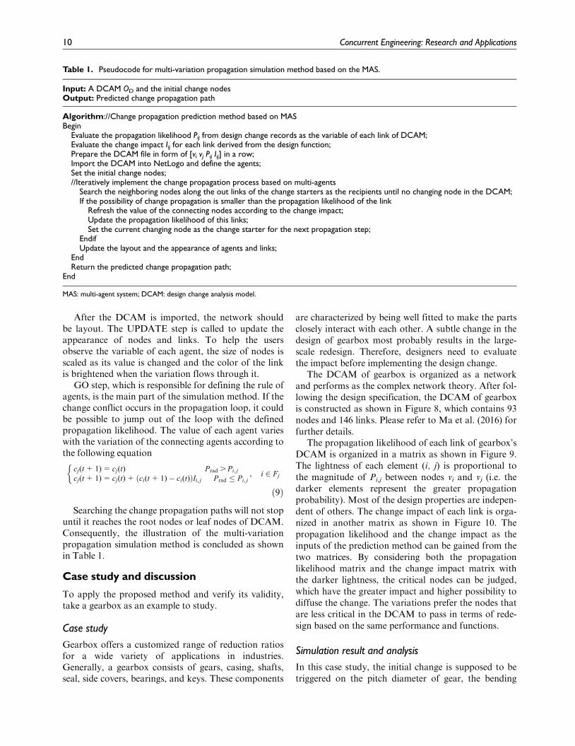
The DCAM of gearbox is organized as a networkand performs as the complex network theory. After fol-lowing the design specification, the DCAM of gearboxis constructed as shown in Figure 8, which contains 93nodes and 146 links. Please refer to Ma et al. (2016) forfurther details.
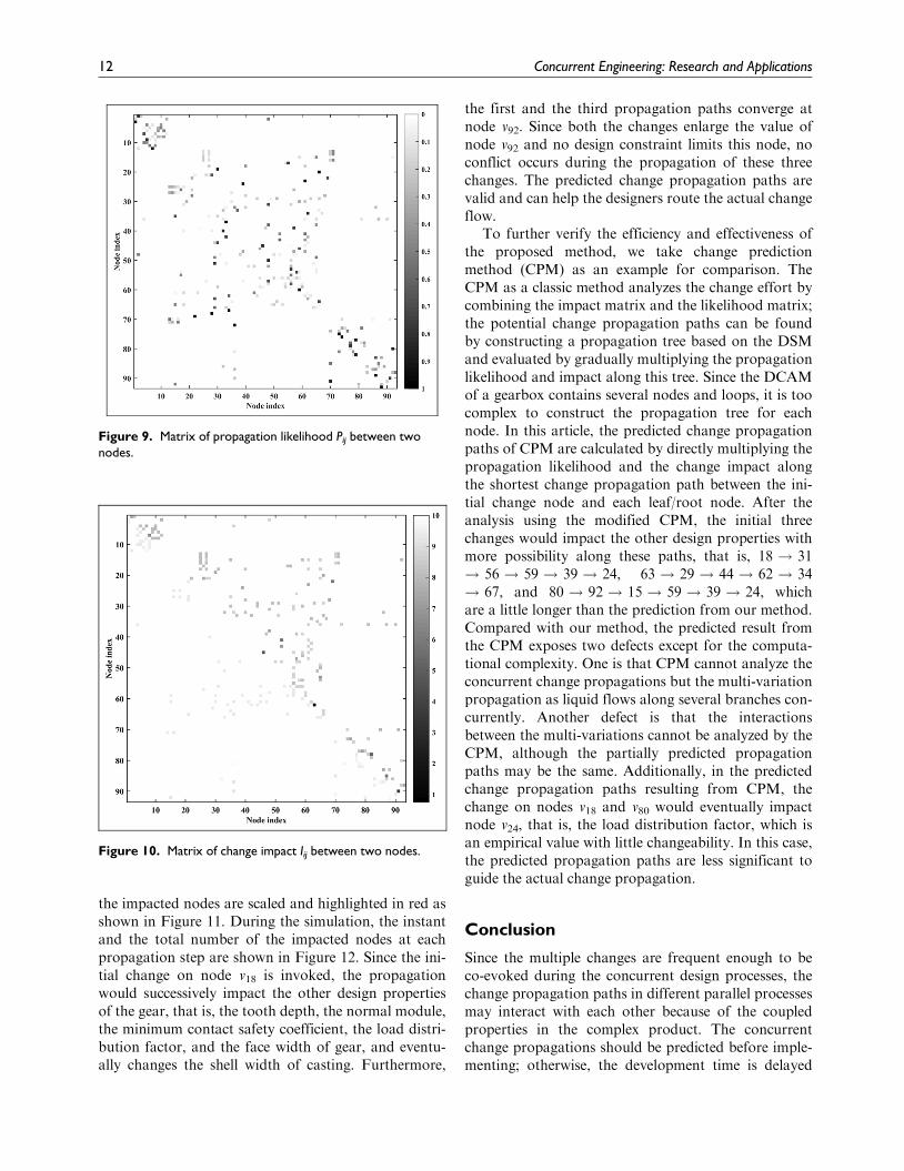
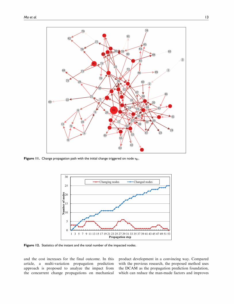
The propagation likelihood of each link of gearbox’sDCAM is organized in a matrix as shown in Figure 9.The lightness of each element (i, j) is proportional tothe magnitude of Pi,j between nodes vi and vj (i.e. thedarker elements represent the greater propagationprobability). Most of the design properties are indepen-dent of others. The change impact of each link is orga-nized in another matrix as shown in Figure 10. Thepropagation likelihood and the change impact as theinputs of the prediction method can be gained from thetwo matrices. By considering both the propagationlikelihood matrix and the change impact matrix withthe darker lightness, the critical nodes can be judged,which have the greater impact and higher possibility todiffuse the change. The variations prefer the nodes thatare less critical in the DCAM to pass in terms of rede-sign based on the same performance and functions.
Simulation result and analysis
In this case study, the initial change is supposed to betriggered on the pitch diameter of gear, the bending
Table 1. Pseudocode for multi-variation propagation simulation method based on the MAS.
Input: A DCAM OD and the initial change nodesOutput: Predicted change propagation path
Algorithm://Change propagation prediction method based on MASBegin
Evaluate the propagation likelihood Pij from design change records as the variable of each link of DCAM;Evaluate the change impact Iij for each link derived from the design function;Prepare the DCAM file in form of [vi vj Pij Iij] in a row;Import the DCAM into NetLogo and define the agents;Set the initial change nodes;//Iteratively implement the change propagation process based on multi-agents
Search the neighboring nodes along the out links of the change starters as the recipients until no changing node in the DCAM;If the possibility of change propagation is smaller than the propagation likelihood of the link
Refresh the value of the connecting nodes according to the change impact;Update the propagation likelihood of this links;Set the current changing node as the change starter for the next propagation step;
EndifUpdate the layout and the appearance of agents and links;
EndReturn the predicted change propagation path;
End
MAS: multi-agent system; DCAM: design change analysis model.
10 Concurrent Engineering: Research and Applications
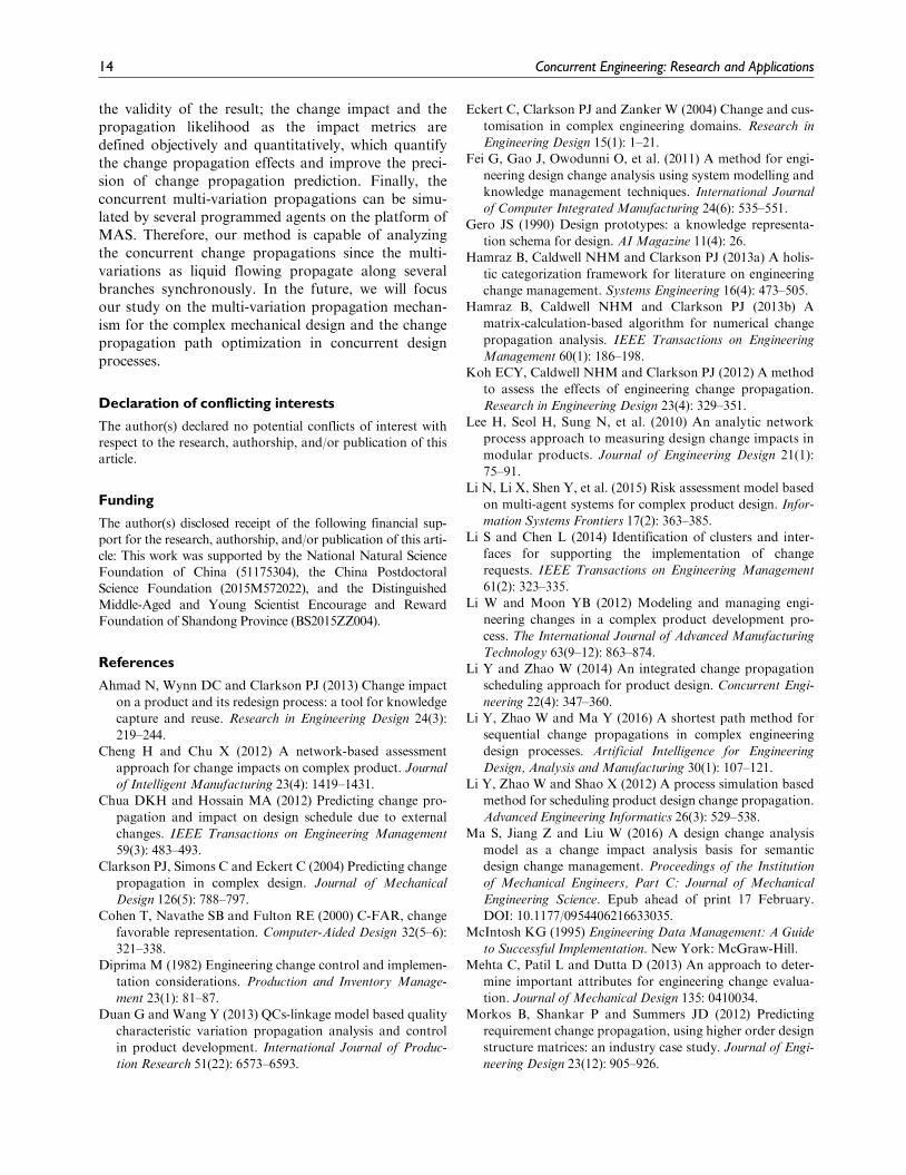
fatigue limit of gear, and the shaft span (correspondingto nodes v18, v63, and v80). The volumes of initial varia-tions are 0.2, 1.0, and 0.5, respectively. After simulating
by MAS, three predicted change propagation pathsare 18 ! 19 ! 30 ! 35 ! 27 ! 15 ! 92, 63 ! 64! 66 ! 33 ! 32, and 80 ! 92, respectively, where
Figure 8. DCAM of a gearbox.
Ma et al. 11
the impacted nodes are scaled and highlighted in red asshown in Figure 11. During the simulation, the instantand the total number of the impacted nodes at eachpropagation step are shown in Figure 12. Since the ini-tial change on node v18 is invoked, the propagationwould successively impact the other design propertiesof the gear, that is, the tooth depth, the normal module,the minimum contact safety coefficient, the load distri-bution factor, and the face width of gear, and eventu-ally changes the shell width of casting. Furthermore,
the first and the third propagation paths converge atnode v92. Since both the changes enlarge the value ofnode v92 and no design constraint limits this node, noconflict occurs during the propagation of these threechanges. The predicted change propagation paths arevalid and can help the designers route the actual changeflow.
To further verify the efficiency and effectiveness ofthe proposed method, we take change predictionmethod (CPM) as an example for comparison. TheCPM as a classic method analyzes the change effort bycombining the impact matrix and the likelihood matrix;the potential change propagation paths can be foundby constructing a propagation tree based on the DSMand evaluated by gradually multiplying the propagationlikelihood and impact along this tree. Since the DCAMof a gearbox contains several nodes and loops, it is toocomplex to construct the propagation tree for eachnode. In this article, the predicted change propagationpaths of CPM are calculated by directly multiplying thepropagation likelihood and the change impact alongthe shortest change propagation path between the ini-tial change node and each leaf/root node. After theanalysis using the modified CPM, the initial threechanges would impact the other design properties withmore possibility along these paths, that is, 18 ! 31! 56 ! 59 ! 39 ! 24, 63 ! 29 ! 44 ! 62 ! 34! 67, and 80 ! 92 ! 15 ! 59 ! 39 ! 24, whichare a little longer than the prediction from our method.Compared with our method, the predicted result fromthe CPM exposes two defects except for the computa-tional complexity. One is that CPM cannot analyze theconcurrent change propagations but the multi-variationpropagation as liquid flows along several branches con-currently. Another defect is that the interactionsbetween the multi-variations cannot be analyzed by theCPM, although the partially predicted propagationpaths may be the same. Additionally, in the predictedchange propagation paths resulting from CPM, thechange on nodes v18 and v80 would eventually impactnode v24, that is, the load distribution factor, which isan empirical value with little changeability. In this case,the predicted propagation paths are less significant toguide the actual change propagation.
Conclusion
Since the multiple changes are frequent enough to beco-evoked during the concurrent design processes, thechange propagation paths in different parallel processesmay interact with each other because of the coupledproperties in the complex product. The concurrentchange propagations should be predicted before imple-menting; otherwise, the development time is delayed
Figure 9. Matrix of propagation likelihood Pij between twonodes.
Figure 10. Matrix of change impact Iij between two nodes.
12 Concurrent Engineering: Research and Applications
and the cost increases for the final outcome. In thisarticle, a multi-variation propagation predictionapproach is proposed to analyze the impact fromthe concurrent change propagations on mechanical
product development in a convincing way. Comparedwith the previous research, the proposed method usesthe DCAM as the propagation prediction foundation,which can reduce the man-made factors and improves
Figure 11. Change propagation path with the initial change triggered on node v81.
Figure 12. Statistics of the instant and the total number of the impacted nodes.
Ma et al. 13
the validity of the result; the change impact and thepropagation likelihood as the impact metrics aredefined objectively and quantitatively, which quantifythe change propagation effects and improve the preci-sion of change propagation prediction. Finally, theconcurrent multi-variation propagations can be simu-lated by several programmed agents on the platform ofMAS. Therefore, our method is capable of analyzingthe concurrent change propagations since the multi-variations as liquid flowing propagate along severalbranches synchronously. In the future, we will focusour study on the multi-variation propagation mechan-ism for the complex mechanical design and the changepropagation path optimization in concurrent designprocesses.
Declaration of conflicting interests
The author(s) declared no potential conflicts of interest withrespect to the research, authorship, and/or publication of thisarticle.
Funding
The author(s) disclosed receipt of the following financial sup-port for the research, authorship, and/or publication of this arti-cle: This work was supported by the National Natural ScienceFoundation of China (51175304), the China Postdoctoral
Science Foundation (2015M572022), and the DistinguishedMiddle-Aged and Young Scientist Encourage and RewardFoundation of Shandong Province (BS2015ZZ004).
References
Ahmad N, Wynn DC and Clarkson PJ (2013) Change impact
on a product and its redesign process: a tool for knowledge
capture and reuse. Research in Engineering Design 24(3):
219–244.Cheng H and Chu X (2012) A network-based assessment
approach for change impacts on complex product. Journal
of Intelligent Manufacturing 23(4): 1419–1431.Chua DKH and Hossain MA (2012) Predicting change pro-
pagation and impact on design schedule due to external
changes. IEEE Transactions on Engineering Management
59(3): 483–493.Clarkson PJ, Simons C and Eckert C (2004) Predicting change
propagation in complex design. Journal of Mechanical
Design 126(5): 788–797.Cohen T, Navathe SB and Fulton RE (2000) C-FAR, change
favorable representation. Computer-Aided Design 32(5–6):
321–338.Diprima M (1982) Engineering change control and implemen-
tation considerations. Production and Inventory Manage-
ment 23(1): 81–87.Duan G and Wang Y (2013) QCs-linkage model based quality
characteristic variation propagation analysis and control
in product development. International Journal of Produc-
tion Research 51(22): 6573–6593.
Eckert C, Clarkson PJ and Zanker W (2004) Change and cus-
tomisation in complex engineering domains. Research in
Engineering Design 15(1): 1–21.Fei G, Gao J, Owodunni O, et al. (2011) A method for engi-
neering design change analysis using system modelling and
knowledge management techniques. International Journal
of Computer Integrated Manufacturing 24(6): 535–551.Gero JS (1990) Design prototypes: a knowledge representa-
tion schema for design. AI Magazine 11(4): 26.Hamraz B, Caldwell NHM and Clarkson PJ (2013a) A holis-
tic categorization framework for literature on engineering
change management. Systems Engineering 16(4): 473–505.Hamraz B, Caldwell NHM and Clarkson PJ (2013b) A
matrix-calculation-based algorithm for numerical change
propagation analysis. IEEE Transactions on Engineering
Management 60(1): 186–198.Koh ECY, Caldwell NHM and Clarkson PJ (2012) A method
to assess the effects of engineering change propagation.
Research in Engineering Design 23(4): 329–351.Lee H, Seol H, Sung N, et al. (2010) An analytic network
process approach to measuring design change impacts in
modular products. Journal of Engineering Design 21(1):
75–91.Li N, Li X, Shen Y, et al. (2015) Risk assessment model based
on multi-agent systems for complex product design. Infor-
mation Systems Frontiers 17(2): 363–385.Li S and Chen L (2014) Identification of clusters and inter-
faces for supporting the implementation of change
requests. IEEE Transactions on Engineering Management
61(2): 323–335.Li W and Moon YB (2012) Modeling and managing engi-
neering changes in a complex product development pro-
cess. The International Journal of Advanced Manufacturing
Technology 63(9–12): 863–874.Li Y and Zhao W (2014) An integrated change propagation
scheduling approach for product design. Concurrent Engi-
neering 22(4): 347–360.Li Y, Zhao W and Ma Y (2016) A shortest path method for
sequential change propagations in complex engineering
design processes. Artificial Intelligence for Engineering
Design, Analysis and Manufacturing 30(1): 107–121.Li Y, Zhao W and Shao X (2012) A process simulation based
method for scheduling product design change propagation.
Advanced Engineering Informatics 26(3): 529–538.Ma S, Jiang Z and Liu W (2016) A design change analysis
model as a change impact analysis basis for semantic
design change management. Proceedings of the Institution
of Mechanical Engineers, Part C: Journal of Mechanical
Engineering Science. Epub ahead of print 17 February.
DOI: 10.1177/0954406216633035.McIntosh KG (1995) Engineering Data Management: A Guide
to Successful Implementation. New York: McGraw-Hill.Mehta C, Patil L and Dutta D (2013) An approach to deter-
mine important attributes for engineering change evalua-
tion. Journal of Mechanical Design 135: 0410034.Morkos B, Shankar P and Summers JD (2012) Predicting
requirement change propagation, using higher order design
structure matrices: an industry case study. Journal of Engi-
neering Design 23(12): 905–926.
14 Concurrent Engineering: Research and Applications
Ouertani MZ (2008) Supporting conflict management in col-laborative design: an approach to assess engineeringchange impacts. Computers in Industry 59(9): 882–893.
Pasqual MC and De Weck OL (2012) Multilayer networkmodel for analysis and management of change propaga-tion. Research in Engineering Design 23(4): 305–328.
Prasad B (2002) Building blocks for a decision-based inte-grated product development and system realization pro-cess. Systems Engineering 5(2): 123–144.
Reddi KR and Moon YB (2011) System dynamics modelingof engineering change management in a collaborative envi-ronment. International Journal of Advanced Manufacturing
Technology 55(9–12): 1225–1239.
Shankar P, Morkos B and Summers JD (2012) Reasons for
change propagation: a case study in an automotive OEM.
Research in Engineering Design 23(4): 291–303.Tang DB, Yin LL, Wang Q, et al. (2016) Workload-based
change propagation analysis in engineering design. Con-
current Engineering 24(1): 17–34.Wynn DC, Caldwell NHM and John Clarkson P (2014) Pre-
dicting change propagation in complex design workflows.
Journal of Mechanical Design 136(8): 81009.Yang F and Duan G (2012) Developing a parameter linkage-
based method for searching change propagation paths.
Research in Engineering Design 23(4): 353–372.
Author biographies
Songhua Ma, born in 1985, is currently a research assistant at Key Laboratory of HighEfficiency and Clean Mechanical Manufacture Shandong University of Ministry of Education,Shandong University, China. She received her PhD from Tsinghua University, China, in 2014and her bachelor degree got from Shandong University, China, in 2008. Her research interestsinclude CAD/CAM and knowledge management.
Zhaoliang Jiang, born in 1971, is currently a professor and PhD supervisor at Key Laboratory ofHigh Efficiency and Clean Mechanical Manufacture, Ministry of Education, ShandongUniversity, China.
Wenping Liu, born in 1973, is currently an associate professor at Key Laboratory of HighEfficiency and Clean Mechanical Manufacture, Ministry of Education, Shandong University,China.
Ma et al. 15


![Naturally Occurring Radioactive Material [NORM] Occurring Radioactive Material [NORM] ... coal did when it was taken from the ground. Because NORM ... Management of Naturally Occurring](https://img.pdfslide.net/doc/110x75/5ad0936b7f8b9ac1478e280f/naturally-occurring-radioactive-material-norm-occurring-radioactive-material-norm.jpg)