Embed Size (px)
Citation preview

EM 1002Multibeam echo sounderBase version & Hull Unit
Maintenance manual


EM 1002
Multibeam echo sounder
Maintenance manual -- Base version & Hull Unit
852--160979 / AA000 / 1--11

NoteKongsberg Simrad AS makes every effort to ensure that the information contained withinthis document is correct. However, our equipment is continuously being improved andupdated, so we cannot assume liability for any errors which may occur.
WarningThe equipment to which this manual applies must only be used for the purpose for whichitwas designed. Improper use ormaintenancemay cause damage to the equipment or injuryto personnel. The usermust be familiar with the contents of the appropriatemanuals beforeattempting to install, operate or maintain the equipment.Kongsberg Simrad AS disclaims any responsibility for damage or injury caused byimproper installation, use or maintenance of the equipment.
CopyrightE 2002 Kongsberg Simrad AS
The information contained within this document remains the sole property of KongsbergSimrad AS. No part of this document may be copied or reproduced in any form or by anymeans, and the information contained within is not to be communicated to a third party,without the prior written consent of Kongsberg Simrad AS.
KONGSBERG SIMRAD ASStrandpromenaden 50, P.O.Box 111, N-3191 Horten, NorwayTelephone +47 33 03 40 00 Telefax +47 33 04 44 24
www.kongsberg-simrad.comSupport: [email protected]
Sales: [email protected] emergency number, outside office hours: +47 99 20 38 01

Maintenance manual
1852-160979 / B
SectionsThisbook is themaintenancemanual for theEM1002multibeam echo sounder. It describeshow to perform intermediate maintenance on the system.
1 IntroductionThis section presents a general introduction to the echo sounder system, anddefines the maintenance philosophy. Refer to page 1.
2 Technical specificationsThis chapter presents the main technical specifications. Refer to page 7.
3 Cable layout and interconnectionsThis chapter describes the cabling, and details the necessary cablespecifications. Refer to page 20.
4 Transceiver UnitThis chapter describes the design and operation of the Transceiver Unit. Eachcircuit board is explained, as well as overall block diagrams and the theory ofoperation. Refer to page 75.
5 Hull Unit ControllerThis chapter describes the Hull Unit Controller. Each circuit board isexplained, as well as overall block diagrams and the theory of operation. Referto page 126.
6 Junction boxThis chapter describes the Remote Control Junction Box. Refer to page 144.
7 TroubleshootingThis chapter provides basic procedures for automatic and traditionaltroubleshooting. Refer to page 148.
8 Replacement proceduresThis chapter explains how to perform replacement of the line replaceable units(LRU). Refer to page 202.
9 Datagram formatsThe formats for data input and output to and from the EM Series multibeamecho sounders are described here. Refer to page 218.
10 System administrationThis chapter provides basic information useful for the EM 1002 systemsupervisor. Refer to page 262.
11 Spare partsThis chapter provides a listing of the line replaceable units with illustrationsand order numbers. Refer to page 298.
12 Drawing file

Kongsberg Simrad EM 1002 / Base version & Hull Unit
2 852-160979 / B
Remarks
ReferencesFurther information about the EM 1002 system may be found in the following manuals:
• EM 1002 Operator manual• EM 1002 Installation manual
The readerThis maintenance manual is intended to be used by a trained maintenance technician orengineer, with experience of electronic and digital circuitry, computers andelectromechanical design. The level of information is based on Kongsberg Simrad’smaintenance philosophy: The onboard technical personnel shall, with the help of thedocumentation and the system’s built-in test functions, be able to identify malfunctions,locate the fault, and replace major parts, modules and components on the “LineReplaceable Unit” (LRU) level. He/she will however not attempt to repair the LRUs.

Maintenance manual
3852-160979 / B
Table of Contents1 INTRODUCTION 1. . . . . . . . . . . . . . . . . . . . . . . . . . . . . . . . . . . . . . . . .
1.1 Overview 1. . . . . . . . . . . . . . . . . . . . . . . . . . . . . . . . . . . . . . . . . . . . . . . .
1.2 Maintenance philosophy 1. . . . . . . . . . . . . . . . . . . . . . . . . . . . . . . . . . . .
1.3 System units 2. . . . . . . . . . . . . . . . . . . . . . . . . . . . . . . . . . . . . . . . . . . . .Overview 2. . . . . . . . . . . . . . . . . . . . . . . . . . . . . . . . . . . . . . . . . . . . . . .Transducer array 2. . . . . . . . . . . . . . . . . . . . . . . . . . . . . . . . . . . . . . . . .Transceiver Unit 2. . . . . . . . . . . . . . . . . . . . . . . . . . . . . . . . . . . . . . . . .Operator Station 3. . . . . . . . . . . . . . . . . . . . . . . . . . . . . . . . . . . . . . . . .Hull Unit Controller (if Hull Unit) 3. . . . . . . . . . . . . . . . . . . . . . . . . . .Hull Unit (optional) 3. . . . . . . . . . . . . . . . . . . . . . . . . . . . . . . . . . . . . . .
1.4 Note about changing AC supply voltage 6. . . . . . . . . . . . . . . . . . . . . . .
2 TECHNICAL SPECIFICATIONS 7. . . . . . . . . . . . . . . . . . . . . . . . . .Notice 7. . . . . . . . . . . . . . . . . . . . . . . . . . . . . . . . . . . . . . . . . . . . . . . . .Interfaces 7. . . . . . . . . . . . . . . . . . . . . . . . . . . . . . . . . . . . . . . . . . . . . . .Physical specifications 7. . . . . . . . . . . . . . . . . . . . . . . . . . . . . . . . . . . .Power requirements 8. . . . . . . . . . . . . . . . . . . . . . . . . . . . . . . . . . . . . . .
2.1 Hull Unit technical and physical specifications 9. . . . . . . . . . . . . . . . . .Hull unit 9. . . . . . . . . . . . . . . . . . . . . . . . . . . . . . . . . . . . . . . . . . . . . . .Environmental specifications 9. . . . . . . . . . . . . . . . . . . . . . . . . . . . . . .Raise/lower motor 9. . . . . . . . . . . . . . . . . . . . . . . . . . . . . . . . . . . . . . . .Pitch servo motor 9. . . . . . . . . . . . . . . . . . . . . . . . . . . . . . . . . . . . . . . .Synchro Transmitter 10. . . . . . . . . . . . . . . . . . . . . . . . . . . . . . . . . . . . . .Limit switches 10. . . . . . . . . . . . . . . . . . . . . . . . . . . . . . . . . . . . . . . . . . .Lubrication 10. . . . . . . . . . . . . . . . . . . . . . . . . . . . . . . . . . . . . . . . . . . . .Relay Unit 10. . . . . . . . . . . . . . . . . . . . . . . . . . . . . . . . . . . . . . . . . . . . . .Remote & Local Control Units 10. . . . . . . . . . . . . . . . . . . . . . . . . . . . . .Hull Unit Controller 11. . . . . . . . . . . . . . . . . . . . . . . . . . . . . . . . . . . . . .Transducer array 11. . . . . . . . . . . . . . . . . . . . . . . . . . . . . . . . . . . . . . . . .
2.2 Environmental specifications 12. . . . . . . . . . . . . . . . . . . . . . . . . . . . . . . .Introduction 12. . . . . . . . . . . . . . . . . . . . . . . . . . . . . . . . . . . . . . . . . . . . .Referenced documents 12. . . . . . . . . . . . . . . . . . . . . . . . . . . . . . . . . . . .Definitions and abbreviations 12. . . . . . . . . . . . . . . . . . . . . . . . . . . . . . .Requirements 12. . . . . . . . . . . . . . . . . . . . . . . . . . . . . . . . . . . . . . . . . . . .Conditions relating to guarantee 18. . . . . . . . . . . . . . . . . . . . . . . . . . . . .
3 CABLE LAYOUT & INTERCONNECTIONS 20. . . . . . . . . . . . . . . .3.1 Introduction 20. . . . . . . . . . . . . . . . . . . . . . . . . . . . . . . . . . . . . . . . . . . . . .
3.2 System cabling 21. . . . . . . . . . . . . . . . . . . . . . . . . . . . . . . . . . . . . . . . . . .

Kongsberg Simrad EM 1002 / Base version & Hull Unit
4 852-160979 / B
Cable layout 21. . . . . . . . . . . . . . . . . . . . . . . . . . . . . . . . . . . . . . . . . . . .Shipyard and system cables 21. . . . . . . . . . . . . . . . . . . . . . . . . . . . . . . .
3.3 Cable specifications 25. . . . . . . . . . . . . . . . . . . . . . . . . . . . . . . . . . . . . . .
Introduction 25. . . . . . . . . . . . . . . . . . . . . . . . . . . . . . . . . . . . . . . . . . . . .System cables 25. . . . . . . . . . . . . . . . . . . . . . . . . . . . . . . . . . . . . . . . . . .Serial lines 27. . . . . . . . . . . . . . . . . . . . . . . . . . . . . . . . . . . . . . . . . . . . . .Transducer cables 27. . . . . . . . . . . . . . . . . . . . . . . . . . . . . . . . . . . . . . . .
3.4 Terminating the transducer cables 28. . . . . . . . . . . . . . . . . . . . . . . . . . . . .
Overview 28. . . . . . . . . . . . . . . . . . . . . . . . . . . . . . . . . . . . . . . . . . . . . . .EM 1002 Transducer array 29. . . . . . . . . . . . . . . . . . . . . . . . . . . . . . . . .Transducer array on hull unit 30. . . . . . . . . . . . . . . . . . . . . . . . . . . . . . .Retrofit installation 32. . . . . . . . . . . . . . . . . . . . . . . . . . . . . . . . . . . . . . .
3.5 Cable gland assembly procedure 35. . . . . . . . . . . . . . . . . . . . . . . . . . . . . .
Purpose 35. . . . . . . . . . . . . . . . . . . . . . . . . . . . . . . . . . . . . . . . . . . . . . . .General procedure 35. . . . . . . . . . . . . . . . . . . . . . . . . . . . . . . . . . . . . . . .Securing and terminating the cables 36. . . . . . . . . . . . . . . . . . . . . . . . . .Multi-diameter modules 36. . . . . . . . . . . . . . . . . . . . . . . . . . . . . . . . . . .Standard type 37. . . . . . . . . . . . . . . . . . . . . . . . . . . . . . . . . . . . . . . . . . . .Additional type 1 (842-093878) 40. . . . . . . . . . . . . . . . . . . . . . . . . . . . .Additional type 2 (541-093642) 41. . . . . . . . . . . . . . . . . . . . . . . . . . . . .
3.6 Cable specifications 43. . . . . . . . . . . . . . . . . . . . . . . . . . . . . . . . . . . . . . .
Introduction 43. . . . . . . . . . . . . . . . . . . . . . . . . . . . . . . . . . . . . . . . . . . . .3.7 Basic cabling requirements 44. . . . . . . . . . . . . . . . . . . . . . . . . . . . . . . . . .
Cable trays 44. . . . . . . . . . . . . . . . . . . . . . . . . . . . . . . . . . . . . . . . . . . . . .Radio Frequency interference 45. . . . . . . . . . . . . . . . . . . . . . . . . . . . . . .Physical protection 45. . . . . . . . . . . . . . . . . . . . . . . . . . . . . . . . . . . . . . .Grounding 45. . . . . . . . . . . . . . . . . . . . . . . . . . . . . . . . . . . . . . . . . . . . . .Cable connections 46. . . . . . . . . . . . . . . . . . . . . . . . . . . . . . . . . . . . . . . .Cable terminations 46. . . . . . . . . . . . . . . . . . . . . . . . . . . . . . . . . . . . . . .Cable identification 46. . . . . . . . . . . . . . . . . . . . . . . . . . . . . . . . . . . . . . .Generic RS-232 serial line (DTE) 47. . . . . . . . . . . . . . . . . . . . . . . . . . . .Generic RS-232 serial line (DCE) 48. . . . . . . . . . . . . . . . . . . . . . . . . . . .Generic RS-232 Serial line 49. . . . . . . . . . . . . . . . . . . . . . . . . . . . . . . . .Generic coax cable 50. . . . . . . . . . . . . . . . . . . . . . . . . . . . . . . . . . . . . . .Serial line to Hull Unit Controller 51. . . . . . . . . . . . . . . . . . . . . . . . . . .On/off from Hull Unit Controller 52. . . . . . . . . . . . . . . . . . . . . . . . . . . .Sound speed probe interface 53. . . . . . . . . . . . . . . . . . . . . . . . . . . . . . . .EM Remote synchronisation and On/Off 54. . . . . . . . . . . . . . . . . . . . . .EM Remote Control with 3 switches 55. . . . . . . . . . . . . . . . . . . . . . . . .

Maintenance manual
5852-160979 / B
Standard AC power cable 56. . . . . . . . . . . . . . . . . . . . . . . . . . . . . . . . . .3-phase AC power to Relay Unit 57. . . . . . . . . . . . . . . . . . . . . . . . . . . .3-phase AC power to hoist motor 58. . . . . . . . . . . . . . . . . . . . . . . . . . . .3-phase AC power to Hull Unit Controller 60. . . . . . . . . . . . . . . . . . . . .Ethernet with RJ45 61. . . . . . . . . . . . . . . . . . . . . . . . . . . . . . . . . . . . . . .VGA Display cable 62. . . . . . . . . . . . . . . . . . . . . . . . . . . . . . . . . . . . . . .Keyboard cable 63. . . . . . . . . . . . . . . . . . . . . . . . . . . . . . . . . . . . . . . . . .Mouse or pointing device cable 64. . . . . . . . . . . . . . . . . . . . . . . . . . . . .Centronics printer cable 65. . . . . . . . . . . . . . . . . . . . . . . . . . . . . . . . . . .Local Control Unit 66. . . . . . . . . . . . . . . . . . . . . . . . . . . . . . . . . . . . . . .Remote Control Unit 67. . . . . . . . . . . . . . . . . . . . . . . . . . . . . . . . . . . . . .Relay Unit control 68. . . . . . . . . . . . . . . . . . . . . . . . . . . . . . . . . . . . . . . .Limit switches and hoist motor brake 69. . . . . . . . . . . . . . . . . . . . . . . . .Synchro feedback 71. . . . . . . . . . . . . . . . . . . . . . . . . . . . . . . . . . . . . . . .Pitch motor power 72. . . . . . . . . . . . . . . . . . . . . . . . . . . . . . . . . . . . . . . .Pitch limit and speed information 73. . . . . . . . . . . . . . . . . . . . . . . . . . . .EM 1002 synchronization 74. . . . . . . . . . . . . . . . . . . . . . . . . . . . . . . . . .
4 TRANSCEIVER UNIT 75. . . . . . . . . . . . . . . . . . . . . . . . . . . . . . . . . . . . .4.1 Description and main functions 75. . . . . . . . . . . . . . . . . . . . . . . . . . . . . .
Overview 75. . . . . . . . . . . . . . . . . . . . . . . . . . . . . . . . . . . . . . . . . . . . . . .The Processing Rack 79. . . . . . . . . . . . . . . . . . . . . . . . . . . . . . . . . . . . . .The Receiver Rack 81. . . . . . . . . . . . . . . . . . . . . . . . . . . . . . . . . . . . . . .
4.2 Theory of operation 82. . . . . . . . . . . . . . . . . . . . . . . . . . . . . . . . . . . . . . .
Overview 82. . . . . . . . . . . . . . . . . . . . . . . . . . . . . . . . . . . . . . . . . . . . . . .Simplified block diagram 82. . . . . . . . . . . . . . . . . . . . . . . . . . . . . . . . . .Control functions 83. . . . . . . . . . . . . . . . . . . . . . . . . . . . . . . . . . . . . . . . .
4.3 Processing rack details 87. . . . . . . . . . . . . . . . . . . . . . . . . . . . . . . . . . . . .Location 87. . . . . . . . . . . . . . . . . . . . . . . . . . . . . . . . . . . . . . . . . . . . . . . .Circuit boards and modules 87. . . . . . . . . . . . . . . . . . . . . . . . . . . . . . . . .
4.4 Receiver rack details 88. . . . . . . . . . . . . . . . . . . . . . . . . . . . . . . . . . . . . . .
Location 88. . . . . . . . . . . . . . . . . . . . . . . . . . . . . . . . . . . . . . . . . . . . . . . .Circuit boards and modules 88. . . . . . . . . . . . . . . . . . . . . . . . . . . . . . . . .
4.5 Circuit board descriptions 89. . . . . . . . . . . . . . . . . . . . . . . . . . . . . . . . . . .Overview 89. . . . . . . . . . . . . . . . . . . . . . . . . . . . . . . . . . . . . . . . . . . . . . .Serial Line Board (CI-104JS) 90. . . . . . . . . . . . . . . . . . . . . . . . . . . . . . .4-Ports Serial Line Board (C114P) 92. . . . . . . . . . . . . . . . . . . . . . . . . . .ROM board 94. . . . . . . . . . . . . . . . . . . . . . . . . . . . . . . . . . . . . . . . . . . . .Ethernet Adapter 95. . . . . . . . . . . . . . . . . . . . . . . . . . . . . . . . . . . . . . . . .VIPer 629 Control Processor Board 99. . . . . . . . . . . . . . . . . . . . . . . . . .

Kongsberg Simrad EM 1002 / Base version & Hull Unit
6 852-160979 / B
Control Processor Board 100. . . . . . . . . . . . . . . . . . . . . . . . . . . . . . . . . . .Beamformer & Signal Processor (BSP) 105. . . . . . . . . . . . . . . . . . . . . . .Processing Unit Power Supply 108. . . . . . . . . . . . . . . . . . . . . . . . . . . . . .Motherboard 109. . . . . . . . . . . . . . . . . . . . . . . . . . . . . . . . . . . . . . . . . . . .Transmitter/Receiver Board (TRB) 110. . . . . . . . . . . . . . . . . . . . . . . . . . .Low Voltage Power Unit (LVPU) 112. . . . . . . . . . . . . . . . . . . . . . . . . . . .High Voltage Power Unit (HVPU) 115. . . . . . . . . . . . . . . . . . . . . . . . . . .Signal Processor Board (SPB31) 116. . . . . . . . . . . . . . . . . . . . . . . . . . . .Receiver Backplane (RXBP) 122. . . . . . . . . . . . . . . . . . . . . . . . . . . . . . . .
5 HULL UNIT CONTROLLER 126. . . . . . . . . . . . . . . . . . . . . . . . . . . . . . .5.1 Description and main functions 126. . . . . . . . . . . . . . . . . . . . . . . . . . . . . .
Overview 126. . . . . . . . . . . . . . . . . . . . . . . . . . . . . . . . . . . . . . . . . . . . . . .Circuit boards and modules 128. . . . . . . . . . . . . . . . . . . . . . . . . . . . . . . . .
5.2 Theory of operation 129. . . . . . . . . . . . . . . . . . . . . . . . . . . . . . . . . . . . . . .Overview 129. . . . . . . . . . . . . . . . . . . . . . . . . . . . . . . . . . . . . . . . . . . . . . .Simplified block diagram 129. . . . . . . . . . . . . . . . . . . . . . . . . . . . . . . . . .
5.3 Hull Unit Controller subrack details 131. . . . . . . . . . . . . . . . . . . . . . . . . . .Location 131. . . . . . . . . . . . . . . . . . . . . . . . . . . . . . . . . . . . . . . . . . . . . . . .Circuit boards and modules 131. . . . . . . . . . . . . . . . . . . . . . . . . . . . . . . . .
5.4 Circuit board descriptions 132. . . . . . . . . . . . . . . . . . . . . . . . . . . . . . . . . . .Overview 132. . . . . . . . . . . . . . . . . . . . . . . . . . . . . . . . . . . . . . . . . . . . . . .Signal Processor board (SPS) 133. . . . . . . . . . . . . . . . . . . . . . . . . . . . . . .Motor and Sensor interfaces board(MOSINT2) 134. . . . . . . . . . . . . . . . . . . . . . . . . . . . . . . . . . . . . . . . . . . . .Servo backplane 140. . . . . . . . . . . . . . . . . . . . . . . . . . . . . . . . . . . . . . . . .Low Voltage Power Supply (LVPS) 142. . . . . . . . . . . . . . . . . . . . . . . . . .Reference Power Supply (MSP10) 143. . . . . . . . . . . . . . . . . . . . . . . . . . .
6 JUNCTION BOX 144. . . . . . . . . . . . . . . . . . . . . . . . . . . . . . . . . . . . . . . . . .6.1 Description 144. . . . . . . . . . . . . . . . . . . . . . . . . . . . . . . . . . . . . . . . . . . . . .
6.2 Remote Control Junction Box 145. . . . . . . . . . . . . . . . . . . . . . . . . . . . . . . .Scope 145. . . . . . . . . . . . . . . . . . . . . . . . . . . . . . . . . . . . . . . . . . . . . . . . . .Location 145. . . . . . . . . . . . . . . . . . . . . . . . . . . . . . . . . . . . . . . . . . . . . . . .General information 146. . . . . . . . . . . . . . . . . . . . . . . . . . . . . . . . . . . . . .
7 TROUBLESHOOTING 148. . . . . . . . . . . . . . . . . . . . . . . . . . . . . . . . . . . . .7.1 Messages 148. . . . . . . . . . . . . . . . . . . . . . . . . . . . . . . . . . . . . . . . . . . . . . . .
Introduction 148. . . . . . . . . . . . . . . . . . . . . . . . . . . . . . . . . . . . . . . . . . . . .7.2 Setup messages 150. . . . . . . . . . . . . . . . . . . . . . . . . . . . . . . . . . . . . . . . . . .
Setup messages 150. . . . . . . . . . . . . . . . . . . . . . . . . . . . . . . . . . . . . . . . . .ESO messages 158. . . . . . . . . . . . . . . . . . . . . . . . . . . . . . . . . . . . . . . . . . .

Maintenance manual
7852-160979 / B
Launchpad messages 162. . . . . . . . . . . . . . . . . . . . . . . . . . . . . . . . . . . . . .Sound Speed Profile Editor messages 185. . . . . . . . . . . . . . . . . . . . . . . . .Ping Display messages 187. . . . . . . . . . . . . . . . . . . . . . . . . . . . . . . . . . . .
7.3 Hardware messages 188. . . . . . . . . . . . . . . . . . . . . . . . . . . . . . . . . . . . . . . .
Hardware messages 188. . . . . . . . . . . . . . . . . . . . . . . . . . . . . . . . . . . . . . .7.4 CPU CMOS SETUP 190. . . . . . . . . . . . . . . . . . . . . . . . . . . . . . . . . . . . . . .
Setup for SSC-486H 190. . . . . . . . . . . . . . . . . . . . . . . . . . . . . . . . . . . . . .Setup for SSC-5x86H 192. . . . . . . . . . . . . . . . . . . . . . . . . . . . . . . . . . . . .
7.5 CMOS SETUP -- standard Processing Unit 195. . . . . . . . . . . . . . . . . . . . .
Setup for VIPer 195. . . . . . . . . . . . . . . . . . . . . . . . . . . . . . . . . . . . . . . . . .7.6 CMOS SETUP -- Processing Unit 201. . . . . . . . . . . . . . . . . . . . . . . . . . . .
Setup for Smartio CI-104JS 201. . . . . . . . . . . . . . . . . . . . . . . . . . . . . . . .
8 REPLACEMENT PROCEDURES 202. . . . . . . . . . . . . . . . . . . . . . . . . . .8.1 Introduction 202. . . . . . . . . . . . . . . . . . . . . . . . . . . . . . . . . . . . . . . . . . . . . .
Overview 202. . . . . . . . . . . . . . . . . . . . . . . . . . . . . . . . . . . . . . . . . . . . . . .Tools required 203. . . . . . . . . . . . . . . . . . . . . . . . . . . . . . . . . . . . . . . . . . .
8.2 Common procedures 204. . . . . . . . . . . . . . . . . . . . . . . . . . . . . . . . . . . . . . .
8.3 Transceiver Unit procedures 205. . . . . . . . . . . . . . . . . . . . . . . . . . . . . . . . .
Overview 205. . . . . . . . . . . . . . . . . . . . . . . . . . . . . . . . . . . . . . . . . . . . . . .Circuit boards and modules 205. . . . . . . . . . . . . . . . . . . . . . . . . . . . . . . . .Fan drawers 207. . . . . . . . . . . . . . . . . . . . . . . . . . . . . . . . . . . . . . . . . . . . .Heater element 207. . . . . . . . . . . . . . . . . . . . . . . . . . . . . . . . . . . . . . . . . . .+ 24V Power Supply 207. . . . . . . . . . . . . . . . . . . . . . . . . . . . . . . . . . . . . .AC mains circuit breaker 208. . . . . . . . . . . . . . . . . . . . . . . . . . . . . . . . . .AC mains filter 209. . . . . . . . . . . . . . . . . . . . . . . . . . . . . . . . . . . . . . . . . .Fuse replacement 209. . . . . . . . . . . . . . . . . . . . . . . . . . . . . . . . . . . . . . . . .
8.4 Hull Unit Controller procedures 211. . . . . . . . . . . . . . . . . . . . . . . . . . . . . .
Overview 211. . . . . . . . . . . . . . . . . . . . . . . . . . . . . . . . . . . . . . . . . . . . . . .Circuit boards and modules 211. . . . . . . . . . . . . . . . . . . . . . . . . . . . . . . . .Fan drawers 212. . . . . . . . . . . . . . . . . . . . . . . . . . . . . . . . . . . . . . . . . . . . .Heater element 212. . . . . . . . . . . . . . . . . . . . . . . . . . . . . . . . . . . . . . . . . . .220 Vac mains circuit breaker 213. . . . . . . . . . . . . . . . . . . . . . . . . . . . . . .220 Vac mains filter 213. . . . . . . . . . . . . . . . . . . . . . . . . . . . . . . . . . . . . .Software replacement 215. . . . . . . . . . . . . . . . . . . . . . . . . . . . . . . . . . . . .Fan drawers 217. . . . . . . . . . . . . . . . . . . . . . . . . . . . . . . . . . . . . . . . . . . . .
9 DATAGRAM FORMATS 218. . . . . . . . . . . . . . . . . . . . . . . . . . . . . . . . . . .9.1 Introduction 218. . . . . . . . . . . . . . . . . . . . . . . . . . . . . . . . . . . . . . . . . . . . . .
9.2 Presentation format 218. . . . . . . . . . . . . . . . . . . . . . . . . . . . . . . . . . . . . . . .

Kongsberg Simrad EM 1002 / Base version & Hull Unit
8 852-160979 / B
9.3 Input datagrams 219. . . . . . . . . . . . . . . . . . . . . . . . . . . . . . . . . . . . . . . . . . .Introduction 219. . . . . . . . . . . . . . . . . . . . . . . . . . . . . . . . . . . . . . . . . . . . .Position 219. . . . . . . . . . . . . . . . . . . . . . . . . . . . . . . . . . . . . . . . . . . . . . . .Attitude data 227. . . . . . . . . . . . . . . . . . . . . . . . . . . . . . . . . . . . . . . . . . . .Sound Speed 232. . . . . . . . . . . . . . . . . . . . . . . . . . . . . . . . . . . . . . . . . . . .Depth input from single beam echo sounder 236. . . . . . . . . . . . . . . . . . .Remote control 237. . . . . . . . . . . . . . . . . . . . . . . . . . . . . . . . . . . . . . . . . .
9.4 Output datagrams 239. . . . . . . . . . . . . . . . . . . . . . . . . . . . . . . . . . . . . . . . .Introduction 239. . . . . . . . . . . . . . . . . . . . . . . . . . . . . . . . . . . . . . . . . . . . .Depth 240. . . . . . . . . . . . . . . . . . . . . . . . . . . . . . . . . . . . . . . . . . . . . . . . . .Raw range and beam angle 243. . . . . . . . . . . . . . . . . . . . . . . . . . . . . . . . .Seabed image 244. . . . . . . . . . . . . . . . . . . . . . . . . . . . . . . . . . . . . . . . . . .Position 245. . . . . . . . . . . . . . . . . . . . . . . . . . . . . . . . . . . . . . . . . . . . . . . .Height 246. . . . . . . . . . . . . . . . . . . . . . . . . . . . . . . . . . . . . . . . . . . . . . . . .Tide 247. . . . . . . . . . . . . . . . . . . . . . . . . . . . . . . . . . . . . . . . . . . . . . . . . . .
9.5 Attitude 248. . . . . . . . . . . . . . . . . . . . . . . . . . . . . . . . . . . . . . . . . . . . . . . . .Heading 249. . . . . . . . . . . . . . . . . . . . . . . . . . . . . . . . . . . . . . . . . . . . . . . .Mechanical transducer tilt 249. . . . . . . . . . . . . . . . . . . . . . . . . . . . . . . . . .Clock 250. . . . . . . . . . . . . . . . . . . . . . . . . . . . . . . . . . . . . . . . . . . . . . . . . .Surface sound speed 251. . . . . . . . . . . . . . . . . . . . . . . . . . . . . . . . . . . . . .Sound speed profile 251. . . . . . . . . . . . . . . . . . . . . . . . . . . . . . . . . . . . . . .Kongsberg Simrad SSP output 252. . . . . . . . . . . . . . . . . . . . . . . . . . . . . .Single beam echo sounder depth 253. . . . . . . . . . . . . . . . . . . . . . . . . . . . .Runtime parameter 253. . . . . . . . . . . . . . . . . . . . . . . . . . . . . . . . . . . . . . .Installation parameters 257. . . . . . . . . . . . . . . . . . . . . . . . . . . . . . . . . . . .
10 SYSTEM ADMINISTRATION 262. . . . . . . . . . . . . . . . . . . . . . . . . . . . .10.1 Introduction 262. . . . . . . . . . . . . . . . . . . . . . . . . . . . . . . . . . . . . . . . . . . . . .
10.2 Passwords 263. . . . . . . . . . . . . . . . . . . . . . . . . . . . . . . . . . . . . . . . . . . . . . .EM 1002 Installation setup 263. . . . . . . . . . . . . . . . . . . . . . . . . . . . . . . . .
10.3 EM 1002 File system 264. . . . . . . . . . . . . . . . . . . . . . . . . . . . . . . . . . . . . .Introduction 264. . . . . . . . . . . . . . . . . . . . . . . . . . . . . . . . . . . . . . . . . . . . .Survey files 264. . . . . . . . . . . . . . . . . . . . . . . . . . . . . . . . . . . . . . . . . . . . .Sound speed profiles 264. . . . . . . . . . . . . . . . . . . . . . . . . . . . . . . . . . . . . .Absorption coefficient file 265. . . . . . . . . . . . . . . . . . . . . . . . . . . . . . . . .Workstation I/O 265. . . . . . . . . . . . . . . . . . . . . . . . . . . . . . . . . . . . . . . . . .Echo sounder parameters 265. . . . . . . . . . . . . . . . . . . . . . . . . . . . . . . . . .BIST files 266. . . . . . . . . . . . . . . . . . . . . . . . . . . . . . . . . . . . . . . . . . . . . .Logfiles 267. . . . . . . . . . . . . . . . . . . . . . . . . . . . . . . . . . . . . . . . . . . . . . . .Operator configuration files 267. . . . . . . . . . . . . . . . . . . . . . . . . . . . . . . .

Maintenance manual
9852-160979 / B
Survey jobs 268. . . . . . . . . . . . . . . . . . . . . . . . . . . . . . . . . . . . . . . . . . . . .TOC files 268. . . . . . . . . . . . . . . . . . . . . . . . . . . . . . . . . . . . . . . . . . . . . . .
10.4 File formats 269. . . . . . . . . . . . . . . . . . . . . . . . . . . . . . . . . . . . . . . . . . . . . .
Introduction 269. . . . . . . . . . . . . . . . . . . . . . . . . . . . . . . . . . . . . . . . . . . . .Survey format and I/O library 269. . . . . . . . . . . . . . . . . . . . . . . . . . . . . . .The survey format 269. . . . . . . . . . . . . . . . . . . . . . . . . . . . . . . . . . . . . . . .
10.5 Survey Predefined Files 286. . . . . . . . . . . . . . . . . . . . . . . . . . . . . . . . . . . .
Introduction 286. . . . . . . . . . . . . . . . . . . . . . . . . . . . . . . . . . . . . . . . . . . . .File locations 286. . . . . . . . . . . . . . . . . . . . . . . . . . . . . . . . . . . . . . . . . . . .Using the Survey Predefined Files 286. . . . . . . . . . . . . . . . . . . . . . . . . . .
10.6 Projection data 287. . . . . . . . . . . . . . . . . . . . . . . . . . . . . . . . . . . . . . . . . . .
Scope and purpose 287. . . . . . . . . . . . . . . . . . . . . . . . . . . . . . . . . . . . . . . .Projection overview 287. . . . . . . . . . . . . . . . . . . . . . . . . . . . . . . . . . . . . .Projection protocol 287. . . . . . . . . . . . . . . . . . . . . . . . . . . . . . . . . . . . . . .Notes 289. . . . . . . . . . . . . . . . . . . . . . . . . . . . . . . . . . . . . . . . . . . . . . . . . .
10.7 Dynamic Projection Library 291. . . . . . . . . . . . . . . . . . . . . . . . . . . . . . . . .
Introduction 291. . . . . . . . . . . . . . . . . . . . . . . . . . . . . . . . . . . . . . . . . . . . .Overview 291. . . . . . . . . . . . . . . . . . . . . . . . . . . . . . . . . . . . . . . . . . . . . . .Dynamic projection library definitions 291. . . . . . . . . . . . . . . . . . . . . . . .Dynamic projection library protocol 291. . . . . . . . . . . . . . . . . . . . . . . . . .Example 292. . . . . . . . . . . . . . . . . . . . . . . . . . . . . . . . . . . . . . . . . . . . . . . .Notes 297. . . . . . . . . . . . . . . . . . . . . . . . . . . . . . . . . . . . . . . . . . . . . . . . . .
11 SPARE PARTS 298. . . . . . . . . . . . . . . . . . . . . . . . . . . . . . . . . . . . . . . . . . . .11.1 Overview 298. . . . . . . . . . . . . . . . . . . . . . . . . . . . . . . . . . . . . . . . . . . . . . . .
11.2 Spares data presentation 298. . . . . . . . . . . . . . . . . . . . . . . . . . . . . . . . . . . .
Spares table 298. . . . . . . . . . . . . . . . . . . . . . . . . . . . . . . . . . . . . . . . . . . . .Parts list codes 299. . . . . . . . . . . . . . . . . . . . . . . . . . . . . . . . . . . . . . . . . . .
11.3 Transceiver Unit 300. . . . . . . . . . . . . . . . . . . . . . . . . . . . . . . . . . . . . . . . . .
Overview 300. . . . . . . . . . . . . . . . . . . . . . . . . . . . . . . . . . . . . . . . . . . . . . .Processing Rack - Reg.no 125-211815 301. . . . . . . . . . . . . . . . . . . . . . . .Processing Rack - Reg.no 125-218141 302. . . . . . . . . . . . . . . . . . . . . . . .Receiver Rack 303. . . . . . . . . . . . . . . . . . . . . . . . . . . . . . . . . . . . . . . . . . .
11.4 Hull Unit Controller 304. . . . . . . . . . . . . . . . . . . . . . . . . . . . . . . . . . . . . . .
Overview 304. . . . . . . . . . . . . . . . . . . . . . . . . . . . . . . . . . . . . . . . . . . . . . .Subrack 304. . . . . . . . . . . . . . . . . . . . . . . . . . . . . . . . . . . . . . . . . . . . . . . .
12 DRAWING FILE 305. . . . . . . . . . . . . . . . . . . . . . . . . . . . . . . . . . . . . . . . . .12.1 Introduction 305. . . . . . . . . . . . . . . . . . . . . . . . . . . . . . . . . . . . . . . . . . . . . .
12.2 Drawing list 305. . . . . . . . . . . . . . . . . . . . . . . . . . . . . . . . . . . . . . . . . . . . . .

Kongsberg Simrad EM 1002 / Base version & Hull Unit
10 852-160979 / B
Document logistics
Rev Date Written Checked Approved
A 12.12.00 EGj BHL EHa
B 02.12.2002 EGj SLP KN
C
D
E
F
G
(The original signatures are recorded in the company’s logistic database.)
Rev Comments
A Original issue.
B Includes the Hull Unit Controller. New boards in the Transceiver Unit. Minorchanges in text.
C
D
To assist us in making improvements to the product and to thismanual, wewould welcomecomments and constructive criticism. Please send all such - in writing or by e-mail - to:
Kongsberg Simrad ASDocumentation Department
P.O.Box 111N-3191 HortenNorway
or e-mail:[email protected]

Maintenance manual
I852--160979 / B
High voltage safety warning
Precautionary measuresThe voltages used to power this equipmentare potentially lethal. Even 110 volts can kill.Whenever possible, the followingprecautionary measures must be taken beforeany work is carried out inside the equipment:S Switch off all high-voltage power supplies.S Check the operation of any door interlocksand any other safety devices.
S Completely discharge all high-voltagecapacitors.
It should be noted that interlocks and safetydevices are normally located only at regularaccess points, and high voltages may beexposed during dismantling.Never work alone on high-voltageequipment!
First aid in the event ofelectric shockNormally, even a high voltage electric shockwill not kill instantly. The victim can still berevived even when his breathing andheart-beat have ceased.Could YOU save someone’s life?In the event of electric shock, the correctactions, performed quickly may well save thevictim’s life. Make sure you know what todo!
Immediate action
While shouting for help, remove the source ofpower from the victim. Switch off the supplyif possible, or using a dry, non-conductivematerial (rubber gloves, broom handle etc.) toinsulate yourself, separate the victim from thesource. If the voltage exceeds 1000 volts,switch off the supply and be ready to catchthe victim. Take care- do not become a victimyourself.Commence first aid on the spot. Continue toshout for assistance till someone arrives.1 Lay the victim flat on his back and loosenany tight clothing (collar, tie, belt etc.).
2 Open his mouth and check for and removeany false teeth, chewing gum etc.
3 Check if the victim is breathing. If not,check if his heart is beating. The pulse isnormally easily found in the main arteriesof the neck, either side of the throat, upunder the chin.
If his heart is beating but he is not breathing,commence artificial respiration. If thevictim’s heart is not beating, commenceExternal Cardiac Massage (ECM). Continueto shout for assistance till someone arrives.
External cardiac massage1 Kneel beside the victim. Place the heel ofone hand in the centre of his chest, at aposition half way between the notchbetween the collar-bones at the top of hischest, and the dip in the breast-bone at thebase of his rib cage. Place the other handon top of the first.
2 Keeping the arms straight and using yourentire weight, press down rapidly so thatthe breast bone is depressed four- five cm,then release the pressure. Repeatrhythmically at a rate of one cycle persecond. This will be hard work, but keepgoing. His life depends on YOU. Do notworry about breaking his ribs - these willheal if he survives.

Kongsberg Simrad EM 1002 / Base version & Hull Unit
II 852--160979 / B
Artificial respiration1 Kneel besides the victim’s head. Place onehand under his neck and lift, allowing hishead to fall back. This will lift his tongueand open the air passage in his throat.
2 Place the palm of the hand on his foreheadto maintain the ”chin-up” position.
3 Using the index finger and thumb of thesame hand, pinch the victim’s nostrilsclosed. Open his mouth.
4 Take a deep breath and cover his mouthwith yours. Blow steadily into his lungs toexpand his chest. Remove your mouthfrom his to allow the air to escape from hischest. You should be able to see his chestdeflate.
5 Repeat the ”inflation-deflation” cycle at arate of about 12 cycles per minute till thevictim begins to breath normally again.
Combining ECM and artificialrespirationIf you are alone, perform one cycle ofartificial respiration for every five cycles ofECM. This will be hard work, but keep going.His life depends on you!If there are other people available to help, oneshould perform the ECM while one performsthe artificial respiration for every five cyclesof ECM. It will be much more efficient withtwo people.Once the victim’s heart is beating and he isbreathing, roll him onto his side and supporthim in that position. As consciousness returnshe may vomit, and this will allow any liquidto drain out of his mouth.
Remove the victim to a hospital as soon aspossible, but do not interrupt the artificialrespiration and ECM cycles till his heart beatand breathing returns.If started quickly and performed correctly, theresuscitation methods described will keep asufficient volume of oxygenated bloodflowing trough the victims body to allow fullrecovery.Proficiency in the resuscitation methods canonly be achieved trough training. Allpersonnel concerned should attend courses ona regular basis. Remember, someone’s lifecould depend on you.
Do you know what to do?

Introduction
1852--160979 / B
1 INTRODUCTION
1.1 OverviewThis is the maintenance manual for the Kongsberg Simrad EM1002 multibeam echo sounder system.The manual contains detailed descriptions of each of the units inthe system. Each circuit board and mechanical assembly isdescribed. The manual also describes the troubleshooting processbased on the Built-In Self test (BIST) software, and it includesprocedures for disassembly and reassembly of the replaceableitems.This manual does not describe the maintenance of the OperatorStation and the peripheral devices (printers, plotters and sensors).For information about these items, refer to the applicablemanufacturer’s documentation.
Note The EM 1002 system can be delivered with a Hull Unit optionally.If you do not have a Hull Unit, disregard the information about theHull Unit and the Hull Unit Controller.
1.2 Maintenance philosophyKongsberg Simrad AS defines three levels for maintenancemanuals:Organizational - You will only perform limited preventive andcorrective maintenance on the system. There is no need fortechnical education or training, and no need for any instruments.Typical tasks are exterior cleaning, or changing fuses.Intermediate -Youwill perform overall preventive and correctivemaintenance on the system. It is recommended that you are aneducated engineer with experience from computerized design andmechanical systems. It is further expected that you can usestandard electronic instruments, such as an oscilloscope. Youshould be trained by Kongsberg Simrad to perform maintenanceon the system. Typical tasks may include troubleshooting, testingand circuit board replacement.Depot -You will perform detailed maintenance on the system andon the circuit boards and modules. You must be an educatedengineer with experience of computerized design and mechanicalsystems. It is further expected that you can use standard electronicinstruments, such as an oscilloscope. You should be trained byKongsberg Simrad to performmaintenance on the system. Typicaltasks are circuit board repair.
Note This maintenance manual is prepared for the intermediate level.

Kongsberg Simrad EM 1002 / Base version & Hull Unit
2 852--160979 / B
1.3 System units
OverviewTheKongsberg SimradEM1002multibeamecho sounder consistsof these main units:• Transducer Array• Transceiver Unit• Operator Station• Hull Unit Controller (if Hull Unit)• Hull Unit (optional)→ The EM 1002 system units are shown on page 4.→ The EM 1002 Hull Unit system units are shown on page 5.
Transducer arrayThe EM 1002 Transducer Array is used both for transmit andreceive. It is semicircular with a radius of 45 cm and 160° angularextent. Its weight in water is approximately 90 kg. Eight 20m longunderwater cables connect the transducer to the Transceiver Unit.The cables are fitted with connectors on the “dry” end.The curved transducer of the EM 1002 makes the accuracydependent upon variation in sound speed at the transducer depth.It is therefore recommended to install a sensor which allowsreal-timemeasurement of sound speed variation if this is expected.The system will take into account the sensor measurements in itscalculations of beam pointing angles and raybending. The systemisprepared for using anAMLSmart Probe directly.Due topossiblemarine growth, and to ease of cleaning or servicing of the sensor,it would be advisable to mount the sensor in a tank inside the hull,and pump water taken from the transducer depth through the tankon permanent installations.
Transceiver UnitThe EM 1002 Transceiver Unit contains the transmit and receiveelectronics and processors for beamforming, bottom detection,and control of all parameters with respect to gain, ping rate andtransmit angles. It has serial interfaces for all time-critical externalsensors such as vessel attitude (roll, pitch, heading and heave),vessel position, and external clock. The Transceiver Unit is a wallmounted cabinet with integrated shock and vibration absorbers.An Ethernet cable connects the Transceiver Unit to the OperatorStation.

Introduction
3852--160979 / B
Operator StationThe Operator Station is a high-performance workstation. Itcontains the operator interface, displays the collected data, andlogs them to disk and tape.
Hull Unit Controller (if Hull Unit)The EM 1002Hull Unit Controller controls the pitch stabilistationsystem. It is only delivered when the system has a Hull Unit.
Hull Unit (optional)The EM 1002 Hull Unit is a electromechanical device designed tophysically lower the transducer array from a safe storage positiondown into the water. The array may be lowered to a maximumdepth of 82 centimeters under its storage position within the hull.TheHull Unit will alsomechanically stabilize the transducer arrayto compensate for the vessel’s pitch movements during the survey.
The EM 1002 Hull Unit is a electromechanical device designed tophysically lower the transducer array from a safe storage positiondown into the water. The array may be lowered to a maximumdepth of xmeters under the vessel’s hull. TheHull Unit is large andheavy, and will only be fitted to relatively large vessels.→ For information about the Hull Unit, refer to the Hull Unit
Instruction manual.

Kongsberg Simrad EM 1002 / Base version & Hull Unit
4 852-160979 / B
(CD4107D)
TransducerArray
Transceiver Unit:- Controller- Receiver
- Transmitter
Operator Station
Not included in standard EM 1002 delivery
Interfaces:Sound Speed SensorTideCenter depth output
External ethernet
Serial interfaces:
Special interfaces:
Positioning systemsAttitude (roll, pitch and heave)HeadingClockDatum heights
Trigger input/outputClock synchronization
Supply voltage:115 or 230 Vac 50/60 Hz
8
Remote Control
Figure 1 EM 1002 system diagram (standard)

Introduction
5852-160979 / B
Transducer
Hull Unit
8
Transceiver Unit:- Controller- Receiver- Transmitter
Hull Unit Control- Motion Interface- Motion Processor- Servo Amplifier
Relay Unit
RemoteControlUnit
LocalControlUnit
Operator Station
Not included in standard EM 1002 delivery
Interfaces:Sound Speed SensorTideCenter depth output
External ethernet
Ser
ial L
ine
(CD4631/GIF)
Junction Box
Figure 2 EM 1002 system diagram (with Hull Unit)

Kongsberg Simrad EM 1002 / Base version & Hull Unit
6 852--160979 / B
1.4 Note about changing AC supply voltageThe EM1002 is wired for 230Vacwhen it comes from the factory.If it is desireable to change to 115 Vac, do the following:• The Processing Unit power must be rewired.
• The switch on the Low Voltage Power Unit must be rewired.• The 220 Vac fans must be changed to 115 Vac type.→ Refer to page 217.

Technical specification
7852--160979 / B
2 TECHNICAL SPECIFICATIONS
NoticeKongsberg Simrad is engaged in continuous developments of itsproducts and reserves the right to alter specifications without priornotice.→ The technical specifications for the Hull Unit and the associated
items are presented on page 9.
Interfaces• Serial lines with operator adjustable baud rate, parity, data andstop bit length for:- Motion sensor (roll, pitch, heave and optionally heading) informat supported by sensors fromAppliedAnalytics, Seatexand TSS
- Gyrocompass in NMEA 0183 HDT format.- Positions in either Simrad 90, NMEA 0183 GGA or GGKformat
- External clock in NMEA 0183 ZDA format- Sound speed profile- Sound speed at transducer- Sea level height (tide)- Datum height(s)- Output of depth straight down in NMEA 0183 DPT format
• Interface for 1 PPS (pulse per second) clock signal• Parallel interface for Postscript colour graphics printer/plotter• Ethernet interface for input of sound speed profile data andoutput of all data normally logged to disk and/or tape
Physical specifications
Transducer Array
Length 398 mm
Depth 887 mm
Width 473 mm
Weight 130 kg (90 kg in water)
Transceiver Unit
Length 746 mm
Depth 630 mm

Kongsberg Simrad EM 1002 / Base version & Hull Unit
8 852--160979 / B
Width 600 mm
Weight 60 kg
Dimensions and weights will depend on your choice ofworkstation model and peripherals.
Power requirements
Operational voltage and frequency
Transceiver Unit 115 / 230 Vac, < 1000 W, 47 to 63 Hz
Operator Station 100 to 240 Vac, < 100 W, 47 to 63 Hz
-- The single phase supply must beprotected with 16A slow--blow fuses
Acceptable transients
Short time (max. 2 sec) 25%, 42 - 69 Hz. . . . . . . . . . . . . . . . . . .
Spikes (max. 50ms) < 1000 V. . . . . . . . . . . . . . . . . . . . . . . . . . . . . . .
Power interrupts
Menu settings, all parameters and the sound speed profile arestored on the Operator Station’s harddisk during operation, sooperation can continue after power interruption. However, the filesystem may be damaged, so the use of an uninterruptable powersupply (UPS) is highly recommended.

Technical specification
9852--160979 / B
2.1 Hull Unit technical and physical specificationsNote The Hull Unit is optional.
Specifications for the complete EM 1002 system is found in theEM 1002 Maintenance manual 852-160697.
Hull unit
Height (above flange) 2150 mm
Weight (Including transducer) Approx. 1000 kg
Distance of raise / lower travel 820 mm
Power supply 220/380/440 Vac,3 phase, 50 Hz
Power consumption 370 W (hoisting)
Environmental specifications
Standards
EMC Noise Emission EN55022 (Class A)
EMC Noise Immunity EN55101
Vibration MIL.STD 167--1
Shock MIL.STD 4141, 4142
Temperature, sonar room 0_C to 55_C
Humidity, sonar room Up to 96%(non--condensing)
Raise/lower motor
Motor type WEGS ODGS 712
Part number 11CX4E
Input voltage 230 / 380 / 440 Vac
Frequency 50 Hz
Phase 3 Phase
Rated power 370 W
Speed 2800 RPM
Water resistance IP 44
Gear ratio 30:1
Pitch servo motor
Motor type RX 520
Part number 499--108416

Kongsberg Simrad EM 1002 / Base version & Hull Unit
10 852--160979 / B
Input voltage 120 Vdc
Normal current 7 A
Max. current (at start--up) max. 30 A
Speed 3600 rpm
Gearbox type MRC 610
Gear ratio 5:1
Dimensions (Complete) Length -- 443 mm
Diameter (Max) 136 mm
Weight 16 kg
Synchro TransmitterMotor type 11 CX 4e
Part number
Input voltage 115 Vdc
Frequency 400 Hz
Normal current
Max. current (at start--up) max. 31 A
Transformation ratio 0.783 + 0.016
Phase shift 4.5_
Total Null voltage 75 V
Output voltage 90 V
Error from E.Z. Max. 7 minutes
Limit switchesType, Hoist limits 1LS3--4PG
Type, Pitch limits 914 CE2--3G
LubricationOil SAE 30 motor oil
Bearing grease Esso Cazar K1
Relay UnitHeight 500 mm
Width 400 mm
Depth 250 mm
Weight 15.5 kg
Remote & Local Control UnitsHeight 241 mm
Width 151 mm

Technical specification
11852--160979 / B
Depth 114 mm max
Weight 1.5 kg
Power supply 24 Vdc
Hull Unit Controller
Height 1110 mm
Width 600 mm
Depth 670 mm max
Weight Approx. 50 kg
Power supply 230 Vdc
Transducer array
Weight 130 kg
Cable length 12.5 m

Kongsberg Simrad EM 1002 / Base version & Hull Unit
12 852-160979 / B
2.2 Environmental specifications
IntroductionThis document contains the standard environmental requirementsfor Kongsberg Simrad AS main product families.The purpose is to have common environmental requirements forall equipment used in Kongsberg Simrad systems installed inseagoing vessels, fixed and floating offshore rigs and industrialinstallations.
Referenced documents• IEC Publication 68 - 2 - 1• IEC Publication 68 - 2 - 2• IEC Publication 68 - 2 - 6• IEC Publication 68 - 2 - 27• IEC Publication 68 - 2 - 30• IEC Publication 68 - 2 - 32
• IEC Publication 68 - 2 - 52• IEC Publication 92 - 504 Sec. 3• IEC Publication 157 - 1• IEC Publication 529• IMO resolution A468 (XII) 1981• European Norm EN 60945
• European Norm EN 50081 part 2• European Norm EN 50082 part 2
Definitions and abbreviationsIEC - International Electrotechnical CommissionIMO - International Maritime Organisation
EN - European Norm
RequirementsThe Kongsberg Simrad products shall as a minimum fulfil theserequirements which are based on national and internationalauthority requirements. The requirements are valid the followinglocations:

Technical specification
13852-160979 / B
1 Inside cubicle and desks.2 Machinery spaces, control rooms, accommodation, bridge
and similar marine environments.3 Open deck, mast and similar industrial environments.4 Submerged.The requirement for storage and transport are for products in itsshipping configuration. If additional requirements is actual forspecific deliveries or projects, these shall be stated in contracts.
Vibration and shock
Vibration during storage and transport
Frequency range 5 to 500 Hz
Excitation level +/- 0.7 g
Reference document: IEC publication 68-2-6
Vibration during operation (locations 1, 2, 3 and 4)
Frequency range 5 to 500 Hz
Excitation level 5 to 13.2 Hz: +/- 1.5 mm13.2 to 100 Hz: 1 g
Sweep rate 1 oct/min
Duration 10 sweeps 5 - 100 - 5 Hz
Reference document: IEC publication 68-2-6 (Test Fc)
Shock during storage and transport, free fall
> 500 kg gross weight max 25 mm fall
< 500 kg gross weight max 50 mm fall
< 200 kg gross weight max 100 mm fall
< 100 kg gross weight max 250 mm fall
< 50 kg gross weight max 500 mm fall
< 21 kg gross weight max 1000 mm fall
Reference document: IEC publication 68-2-32

Kongsberg Simrad EM 1002 / Base version & Hull Unit
14 852-160979 / B
Shock during operation
Location Shocktype I Shocktype II Shocktype III
General 50 m/s2 100 m/s2 -
Bottom sections of the hull 100 m/s2 300 m/s2 -
Ice-going vessel 100 m/s2 300 m/s2 -
Steeringmachine room 50 m/s2 100 m/s2 -
Crane and load equipment 100 m/s2 300 m/s2 500 m/s2
Shock type I: Long duration (11 ms), low acceleration amplitudeShock type II: Medium duration (6 ms), medium acceleration amplitudeShock type III: Short duration (1 ms), high acceleration amplitude
Reference document: IEC publication 68-2-27, test Ea: Shock
Dry heat
Storage and transport
Ambient temperature range -40 to +70 degrees C
Reference documents:IEC publication 68-2-1 (Test Ab and Ad)IEC publication 68-2-2 (Test Bb and Bd)
Operation, ambient temperature range
Location 1 0 to +70 degrees C
Location 2 0 to +55 degrees C
Location 3 -25 to +70 degrees C
Bridge equipment shall not fail when powered up at -10 de-grees C
Reference documents:IEC publication 68-2-1 (Test Ab and Ad)IEC publication 68-2-2 (Test Bb and Bd)
Cyclic humidity
Specifications for locations 1, 2, 3 and 4.
Low temperature +20 degrees C
High temperature +55 degrees C
Humidity 95% Relative
Reference documents: IEC publication 68-2-30 (Test Db)

Technical specification
15852-160979 / B
High voltage
Specifications for locations 1, 2, 3 and 4.
All components that may be subject to damage can be re-moved prior to this test.
DC voltage AC voltage Test voltage (AC)
0 to 75 0 to 60 500
76 to 150 61 to 125 1250
151 to 300 126 to 250 1500
301 to 450 251 to 380 1800
451 to 600 381 to 500 2000
601 to 800 501 to 660 2300
Reference documents: IEC publication 157-1
Insulation resistance
Specifications for locations 1, 2, 3 and 4.
All components that may be subject to damage can be re-moved prior to this test. The test shall be carried out beforeand after the humidity test, low temperature test and saltmist test.
Rated supply (V) Test voltage (DC) Before After
Under 65 V 2x supply volt-age; min. 24 V
10 Mohm 1 Mohm
Over 65 V 500 V 100 Mohm 10 Mohm
Reference documents: IEC publication 92-504, Section 3
Power supply offsets from nominal value
Specifications for locations 1, 2 and 3.
Frequency deviation +/- 5%
Frequency transient +/- 15%
Voltage deviation +10 to -15%
Voltage transient +/- 20%
Reference documents: IEC publication 92-504, Section 3

Kongsberg Simrad EM 1002 / Base version & Hull Unit
16 852-160979 / B
Power supply failure
Specifications for locations 1, 2 and 3.
Three interruptions to the supply with a minimum of breaktime of 10 mil.seconds with repition rate of 10 seconds.After restart there shall be no corruption of programme, dataor operation.
Reference documents: IEC publication 92-504 Section 3
Salt mist
Specifications for locations 3 and 4.
The chosen items shall functioning after test.
Reference documents: IEC publication 68-2-52 (Test Kb)
Enclosure
Equipment mounted inside cubicles and desks: IP00
Bridge, etc. equipment: IP22
Machine- and steering machine room equipment: IP44
Open deck and mast equipment: IP56
Underwater equipment: (transducers etc.) IP68
Reference documents: IEC publication 259
Dynamic inclination
Specifications for locations 1, 2 and 3.
The equipment is rolled to an angle of 22.5 degrees eitherway within a time period of 10 seconds. The test in eachdirection must be carried out for minimum 15 minutes.
Reference documents: IEC publication 62-504 Section 3
Acoustic noise
Specifications for locations 2, Bridge equipment
Maximum noise level 55 dB (A) / 1 m
Reference documents: IMO resolution A 468 (XII) 1981
Electromagnetic compatibility (EMC)
Emission requirements
Location European Norm

Technical specification
17852-160979 / B
2 and 3(All electronic and electricequipment above water)
EN50081-2Generic emission standard,Part 2: Industrial environ-ment
2 and 3(Bridge, open deck and mastequipment)
EN60945General requirements,methods of testing and re-quired test results Marine Na-vigational Equipment.
Immunity requirements
Location European Norm
2 and 3(All electronic and electricequipment above water)
EN50082-2Generic immunity standardPart 2: Industrial environ-ment
2 and 3(Bridge, open deck and mastequipment)
EN60945General requirements,methods of testing and re-quired test results for MarineNavigational Equipment
Note Specifications for commercial equipment, such as computersdelivered with the system, are in accordance with those of therespective equipment.

Kongsberg Simrad EM 1002 / Base version & Hull Unit
18 852-160979 / B
Conditions relating to guarantee
Warranty
TheCustomer’s right towarranty only covers damage due to faultsin fabrication or components used. The warranty is valid for 12months from installation, andmaximum 18months from delivery.
Kongsberg Simrad AS will perform warranty repairs or changefaulty components in their workshop during normal workinghours. Transport to and from Kongsberg Simrad AS take place atthe customers risk and cost. Any other costs such as customs duty,fees and insurance will also be covered by the customer. If therepair takes place outside the Kongsberg Simrad AS workshop,travel expenses, per diem, lodging and 50% of travel time (basedon rates for repair work) will be charged.
The warranty is void in the following cases:
A) Connections to the equipment or other work has taken placewithout permission from Kongsberg Simrad AS.
B) Damage has occurred as a consequence of unskilled orerroneous work on the equipment or neglectful maintenance.
C) If the terms of payment has not been satisfied. Parts such aspacking, fuses, lamps and simple electronic components areregarded as consumables and are as such wholly or partly exemptfrom the warranty.
Repairs
The customer shall cover repairs performed after the validity timeof the warranty, in full. Customer shall also cover transport to andfrom Kongsberg Simrad AS’ workshop. If the repair-work takesplace outside Kongsberg Simrad AS’ workshop, the customer willcover travel costs, per diem, lodging and travel time in addition tothe time spent on the actual repair.
The warranty on repair work-limited to 3 months after time ofrepair-is limited to the fault which was sought repaired. Thecustomer shall point out faults of the repair-work performed.Otherfaults occurring will not be covered by the warranty. If KongsbergSimrad AS can offer replacement equipment during the period ofrepair, the customer shall cover transport and insurance of this.

Technical specification
19852-160979 / B
Validity
Thiswarranty is effective onlywhen awarranty certificate or otherproof of purchase and equipment serial number are presented.Furthermore, the installation and the operation of the equipmentmust have been carried out as instructed in the product manual(s).Warranty liability does not apply to any equipment which hasbecome inoperative due to misuse, accident, neglect, sea waterdamage or unauthorised repair.
Kongsberg Simrad AS will not be liable for any loss, incidental orconsequential damages whether based upon warranty, contract ornegligence, or arising in connection with the sale, installation, useor repair of the product. Consequential damages include, but arenot limited to, any loss of profit, property damage or personalinjury.
The terms of warranty as described do not affect your statutoryrights.

Kongsberg Simrad EM 1002 / Base version & Hull Unit
20 852--160979 / B
3 CABLE LAYOUT & INTERCONNECTIONS
3.1 IntroductionThe standard cables used between the EM 1002 system units andbetween the units and their external devices are shown here. Forlarger installations where the EM 1002 is a subsystem, the cableswill also be shown in the cable layout plan and interconnectiondiagram specific for the vessel into which the system is installed.
Note All cable connections may have to be made in accordance with theguidelines laid down by the vessel’s classification society.
If no such guidelines exist, Kongsberg Simrad AS recommendsthatDet norskeVeritas (DnV)ReportNo. 80-P008 «Guidelines forInstallation and Proposal for Test of Equipment» be used as aguide.

Cable layout
21852--160979 / B
3.2 System cabling
Cable layout
The interconnection cables are identified on the cable layoutdrawings. Each cable is then listed in the corresponding list, whichcontains the required cable specifications. On the following pages,each cable is identified with the appropriate terminations.
→ Refer to the cable layout in figures 3 and 4.
Shipyard and system cables
General
Each individual cable is identifiedon the cable plan.The cables fallinto two categories:
• Cables provided by the installation shipyard or owner
• System cables supplied with the delivery
Shipyard cables
The cables that must be provided by the shipyard or owner areidentified as such in the tables. Note that the cable specificationsgiven are the minimum specifications.
For each cable, the following information is provided:
• Connection to be made on each end of the cable (includingsystem unit, terminal board identification and plug/socket to beused)
• Number of cores
• Recommended cable type
• Minimum cable specifications
The necessary considerations must be taken to suit specialrequirements. Kongsberg Simrad accepts no responsibility fordamage to the system or reduced operational performance if thisis caused by improper cabling.
System cables
Several cables will be supplied with the system. Such cablesnormally comprise power cables for peripheral equipment, andinterconnection cables for computers and/or workstations. Thesecables will normally be delivered with the units.

Kongsberg Simrad EM 1002 / Base version & Hull Unit
22 852--160979 / B
Figure 3 EM 1002 Cable plan - Operator Station
Externalhard disk
Externaltape storage
OperatorStation
Keyboard
Mouse or otherpointing device
(CD4526A)
C4SCSI cable
C3Mouse
C1Display
C2Keyboard
C8AC power
C9AC power
C10AC power
C11AC power
C18Coax to Transceiver Unit
Ethernet to Transceiver Unit C17
C14 Ship's ethernet
C13 Auxiliary ethernet devices
C12 AC Power
C6 Parallel interface to printer/plotter
C24 Remote
C19 Synchronisation system
C16 Depth/Tide (Serial B)
C7
Ethe
rnet
C15 Sound speed sensor (Serial A)
C5SCSI cable
Remotecontrol
Ethernetswitch
The synchronisation system may be connectedto the remote control box, or directly to theTransceiver Unit.
The ethernet interface to the Transceiver Unit mayeither be connected to the switch box, or directly to a
secondary interface board in the computer.

Cable layout
23852--160979 / B
Figure 4 EM 1002 Cable plan - Transceiver Unit
Transceiver Unit
TransducerArray
8
(CD
4526
D /
GIF
/ W
MF)
C20Position system (serial 1)
C21Motion sensor (serial 2)
C22Auxiliary interface 1 (serial 3)
C23Auxiliary interface 2 (serial 4)
C17Ethernet to Operator Station
C251 PPS
C24Remote
C19Synchronisation system(Only used on systems with a SSU unit)
C18Coax to Operator Station
C27Hull Unit Controller(Only used on systems with a hull unit installed)
C26100 - 240 Vac power 50/60 Hz, 10 A
Transducer cablessupplied with thearray.
(Note: On systems with aHull Unit, or when an EM 1000transducer array is used, thesecables are routed thrugh a junctionbox.)
Junction Box(optional)

Kongsberg Simrad EM 1002 / Base version & Hull Unit
24 852--160979 / B
Figure 5 EM 1002 Cable plan - Hull Unit
Transducer
Hull Unit
-- 8 - Transducer cables
TransceiverUnit
Hull UnitController
Relay Unit
RemoteControlUnit
LocalControl
Unit
(CD
4526
C /
GIF
/ W
MF)
Junction Box
230 Vac power50/60 Hz, 16 A
230/380 Vac power3-phase
50/60 Hz, 10 A
230/380 Vac power3-phase
50/60 Hz, 10 A
Syn
chro
feed
back
Remaining Transceiver Unitcabling: See previous drawing
Pitc
h M
otor
pow
er
Pitc
h lim
its a
nd s
peed
info
rmat
ion
Rel
ay U
nit c
ontro
l
C36
C37
C38
C39C40
C41 C42
C35
C32C33C34
C30 ControlC31 Remote on/off

Cable layout
25852--160979 / B
3.3 Cable specifications
IntroductionThe cables identified in the cable plan are listed here. Each cableis identfied with a cable identificator (Cx).The transducer cables are not listed. These are supplied with thesystem.MFS = Manufacturer supply
System cables
OPERATOR STATION CABLES
ID Specifications From/To MFS
C1 Page 62 / Note 1 Operator Station -- Display unit Yes
C2 Page 63 / Note 1 Operator Station -- Keyboard Yes
C3 Page 64 / Note 1 Keyboard -- Mouse Yes
C4 SCSI / Note 1 Operator Station -- External hard disk Yes
C5 SCSI / Note 1 External hard disk -- External tape storage Yes
C6 Page 65 / Note 2 Operator Station -- Plotter (Parallel)
C7 Page 61 Ethernet cable
C8 Page 56 Display -- AC power Yes
C9 Page 56 Operator Station -- AC power Yes
C10 Page 56 External disk storage -- AC power Yes
C11 Page 56 External tape storage -- AC power Yes
C12 Page 56 / Note 10 Power to Ethernet switch
C13 Page 61 / Note 9 Auxiliary ethrnet devices
C14 Page 61 Operator Station -- Ship’s network (Ethernet)
C15 Page 53 Operator Station Port A -- Sound Speed sensor (Input)
C16 Page 49 Operator Station Port B -- Depth/Tide sensor (Input)
C17 Page 61 / Note 3 Operator Station -- Transceiver Unit
C18 Page 50 / Note 3 Operator Station -- Transceiver Unit
TRANSCEIVER UNIT CABLES
ID Specifications From/To MFS
C17 Page 61 / Note 3 Transceiver Unit -- Operator Station
C18 Page 50 / Note 3 Transceiver Unit -- Operator Station
C19 Page 74 Synchronisation system (SSU)
C20 Page 49 Transceiver Unit -- Positioning system (Input)

Kongsberg Simrad EM 1002 / Base version & Hull Unit
26 852--160979 / B
ID MFSFrom/ToSpecifications
C21 Page 49 Transceiver Unit -- Motion sensor (Input)
C22 Page 49 Transceiver Unit -- Auxiliary 1 (Input)
C23 Page 49 Transceiver Unit -- Auxiliary 2 (Input)
C24 Page 54 / Note 6 Transceiver Unit -- Remote control unit
C25 Page 50 Transceiver Unit -- 1 PPS clock (Input)
C26 Page 56 Transceiver Unit -- AC power
C27 Note 8 Transceiver Unit -- Hull Unit Controller
C28 Not used
C29 Not used
TRANSDUCER CABLES
ID Specifications From/To MFS
TD cables Note 7 8 x Transducer cables Yes
JB cables Note 4 8 x Junction box -- Transceiver Unit Yes
Note 1 - This is a standard computer cable provided with theOperator Station.
Note 2 - The workstation only provides one parallel interface toplotter or printer. In most cases, plotters and printers are connecteddirectly to the ship’s ethernet network.
Note 3 - The interface between the Operator Station and theTransceiver Unit is made with either C17 or C18. In some casestwo ethernet cablesmay be used. These are then identified asC17Aand C17B.
Note 4 -These cables are only required if the junction box is used.
Note 5 -This cable is only required if a hull unit system is installed.
Note 6 - The Remote connector on the Transceiver Unit hasseveral functions. It is normally usedwith a dedicated junction boxfor on/off control and external triggering.
Note 7 - The transducer cables are fixed to the array. The cablesare terminated according the the requirements set by theinstallation method.
Note 8 - Cable C27 is only used if a Hull Unit is implemented.
Note 9 - Auxiliary ethernet devices may include a secondTransceiver Unit in a dual frequency multibeam system.
Note 10 -Depending on make and model, the power supply to theEthernet switch may also be comprised by a small commercialpower supply.

Cable layout
27852--160979 / B
Serial linesThe EM1002 uses several serial lines to interface with sensors andperipherals. Although the normal implementation is described inthis document, the set-up of these interfaces may easily be alteredin the echo sounder.
Operator Station serial lines
Serial Port A - This serial port is normally a 25-pin femaleD-connector. This port is usually a used to interfacewith the soundvelocity sensor.Serial Port B - This serial port is normally a 9-pin maleD-connector. This port is usually used for a sound speed profiler,or a depth/tide sensor.
Transceiver Unit serial lines
The Transceiver Unit is equipped with four serial lines. Allconnectors are 9-pin male D-connectors. The serial lines arenormally set up as follows:Serial Port 1 - Positioning systemsSerial Port 2 -Motion sensorSerial Port 3 - Auxiliary 1Serial Port 4 - Auxiliary 2
Transducer cablesThe transducer cables are permanently fastened to the transducerarray. The cables are connected to theTransceiver Unit with 50-pin“D” connectors. If a hull unit is installed, or if an EM 1000transducer array is used, and optional junction box must be used.→ The termination of the transducer cables is described on page 28.

Kongsberg Simrad EM 1002 / Base version & Hull Unit
28 852--160979 / B
3.4 Terminating the transducer cables
OverviewThe transducer cables are supplied with the transducer array, andthey are not identified with an Wxxx number on the cable plan.
The cables are normally terminated to the eight 50-pin D-subconnectors on the Transceiver Unit. However, certain installationswill require a junction box if the transducer array is installed on ahull unit, or if an existing EM 1000 transducer array is used(retrofit installation).Depending on the array and installationused,the following different plug types and terminations are used:
• A transducer array mounted on a hull unit uses ’Berg’connectors. The transducer cables are terminated in the junctionbox. Eight cables with 50-pin D-sub connectors in each end areused between the junction box and the Transceiver Unit.
• A transducer array mounted directly under the hull uses 50-pinD-sub connectors. These connect directly to the TransceiverUnit.
• The EM 1000 transducer array used for retrofit installationsuses small coax connectors. The transducer cables areterminated in the junction box. Eight cables with 50-pin D-subconnectors in each end are used between the junction box andthe Transceiver Unit.
• From 2002 the transducer cables are terminated like theEM1000 transducer, with small coax connectors.

Cable layout
29852--160979 / B
EM 1002 Transducer arrayWhen the transducer array is mounted under the hull, the eighttransducer cables are terminated into the eight D-sub connectorsunder the Transceiver Unit.The cables on the transducer array are identified as follows:RXT1/Cn
where n=1 through 4, andRXT2/Cn
where n=1 through 4.
The cables are also identified with a number between 1 and 8, asfollows:• RXT1/C1 - Cable 8• RXT1/C2 - Cable 7• RXT1/C3 - Cable 6• RXT1/C4 - Cable 5• RXT2/C1 - Cable 4• RXT2/C2 - Cable 3• RXT2/C3 - Cable 2• RXT2/C4 - Cable 1
RXT1/C41 PPS
115/230VAC 50/60Hz300W
Serial port 4
EXTERNAL SENSORS
RemoteSerial port 1Serial port 2Serial port 3ETHERNET
Hull unit
(CD5823 / 871-211807A)
Eight 50-pin female "D" connectorsfor the transducer cables
Ground
Ethernetconnectors
1 PPS coaxconnector
Serial lines 4 - 19-pin male "D" connectors
Hull Unit9-pin male "D" connector
Remote control9-pin male "D" connector
115 / 230 Vac50 / 60 Hz - 300 W
RXT1/C3 RXT1/C2 RXT1/C1
RXT2/C3RXT2/C4 RXT2/C2 RXT2/C1
Figure 6 The connector panel under the Transceiver Unit

Kongsberg Simrad EM 1002 / Base version & Hull Unit
30 852-160979 / B
Transducer array on hull unitWhen the transducer array is mounted on a hull unit, the D-subconnectors must be replaced. Smaller connectors are required dueto the physical limitations of the hull unit.
TheBerg connectors are standard for hull unit mounted transducerarrays. To make these fit to the Transceiver Unit, a junction box isused. The transducer cables are terminated in the junction box, andeight other cables with 50-pin D-sub connectors in each end areused between the junction box and the Transceiver Unit.
Figure 7 EM 1002 termination: ’Berg’ connectorsfrom a hull unit mounted transducer
8Transducer cable no:...
Sockets for the cables to the Transceiver Unit
7 6 5 4 3 2 1
(CD
4904
B / 8
73-2
1264
6/A)
1
16
Cable 1(RXT2/C4)
2
The termination of the cables onto the circuit board is described ona sticker located on the inside of the Junction Box door. The sameinformation is provided here.
The cables on the transducer array are identified as follows:RXT1/Cn
where n=1 through 4, andRXT2/Cn
where n=1 through 4.

Cable layout
31852-160979 / B
Figure 8 EM 1002 termination: ’Berg’ connectorsfrom a hull unit mounted transducer
8Channel 16
Transducer cable no:...
Sockets for the cables to the Transceiver Unit
Channel 1
7 6 5 4 3 2 1
(CD
4904
/ 87
3-21
2646
/A)
The cables are also identified with a number between 1 and 8, asfollows:
• RXT1/C1 - Cable 8• RXT1/C2 - Cable 7• RXT1/C3 - Cable 6• RXT1/C4 - Cable 5• RXT2/C1 - Cable 4• RXT2/C2 - Cable 3• RXT2/C3 - Cable 2• RXT2/C4 - Cable 1

Kongsberg Simrad EM 1002 / Base version & Hull Unit
32 852-160979 / B
Retrofit installation
EM 1000 Transducer array
The transducer array is connected with eight cables. Each cablecontains 16 indivdual coax cables, and each coax is terminated ina small coax connector.
Figure 9 Junction Box terminations
8Transducer cable no:...
Sockets for the cables to the Transceiver Unit
7 6 5 4 3 2 1
(CD
4905
c/21
0953
/A)
Coax 1
Coax 16
Cable 1
The cable identified as RXT2/C4 (Cable 1) is connected to theright-most circuit board in the Junction Box (board 1). The cable’scoax 1 (= Channel 1) is connected to socket 16 (= Channel 16 onthe top socket) on the board. The channels are thus connected inthe reverse order on each board.The remaining coax connectors are terminated according to thefollowing pattern:Cable 1:
Cable Channel Board Board Ch SW Ch
1 1 1 16 128
1 2 1 15 127
1 3 1 14 126
1 4 1 13 125
etc

Cable layout
33852-160979 / B
816 32 48 64 80
81
96
9765493317
= Board number= SW channel numbern
1
128
113
1127 6 5 4 3 2 1
n(CD4905B/210953/A)
Figure 10 Physical connectors related to software channels
Cable 2:
Cable Channel Board Board Ch SW Ch
2 1 2 16 112
2 2 2 15 111
2 3 2 14 110
2 4 2 13 109
etc
Cable 3:
Cable Channel Board Board Ch SW Ch
3 1 3 16 96
3 2 3 15 95
3 3 3 14 94
3 4 3 13 93
etc

Kongsberg Simrad EM 1002 / Base version & Hull Unit
34 852-160979 / B
Cable 4:
Cable Channel Board Board Ch SW Ch
4 1 4 16 80
4 2 4 15 79
4 3 4 14 78
4 4 4 13 77
etc
Cable 5:
Cable Channel Board Board Ch SW Ch
5 1 5 16 64
5 2 5 15 63
5 3 5 14 62
5 4 5 13 61
etc
Cable 6:
Cable Channel Board Board Ch SW Ch
6 1 6 16 48
6 2 6 15 47
6 3 6 14 46
6 4 6 13 45
etc
Cable 7:
Cable Channel Board Board Ch SW Ch
7 1 7 16 32
7 2 7 15 31
7 3 7 14 30
7 4 7 13 29
etc
Cable 8:
Cable Channel Board Board Ch SW Ch
8 1 8 16 16
8 2 8 15 15
8 3 8 14 14
8 4 8 13 13
etc

Cable layout
35852--160979 / B
3.5 Cable gland assembly procedure
PurposeCable glands are used whenever a cable passes through awater-tight bulkhead or into a cabinet, to seal the opening throughwhich the cable passes and to protect the cable from abrasion onthe edges of the hole. Follow the guidelines detailed here wheninstalling cables through cable glands.
Note There are many different types of cable gland on the market. Thisprocedure describes the types used (now and previously) asstandard in the units manufactured by Kongsberg Simrad. Thecable glands are not supplied with the system.
Even though the cabinets from Kongsberg Simrad may beprepared for specific types, the installation shipyard will beresponsible for selecting cable gland types and installing them.
Note The screen in transducer cables must never be connected to ship’sground in the cable glands!
General procedure1 Ensure all the cables to be connected are completely isolated
from any power sources.- I.e. Switchoff and remove the supply fuses from anyunitsor systems into which the cables are already connected.
2 Select the cable to be connected into the cabinet, and selectthe cable gland through which the cable is to pass.
Note Aminimum of 5 cm (recommended 5 - 10 cm) of slack cable mustbe allowed, both inside and outside the cabinet, when installingcables. This is to allow for vibration damping, maintenance andmeasurement errors. Always double-check your measurementsbefore taking any irreversible actions.
3 Depending on whether the cable has already been installedin conduits, either.a (installed) measure the maximum length of cablerequired to reach from the final cable clip outside thecabinet to the terminal blocks inside the cabinet, add 20cm, then remove the excess cable,
or:b (loose cable) measure the maximum length of wirerequired to reach from the cable gland to the terminalblocks inside the cabinet, add 20 cm. and mark the cable.

Kongsberg Simrad EM 1002 / Base version & Hull Unit
36 852--160979 / B
Note The cable’s outer insulation will extend into the cable gland to apoint approximately 5 mm outside the outer surface of the cabinetwall into which the cable gland is secured.4 Taking care not to damage the screening, carefully remove
the outer insulation from the required cable length.5 Leaving an appropriate length of the screen exposed from
the insulation, cut off the remainder.
Securing and terminating the cables1 Referring to the wiring diagram and ensuring that there is 5
to 10 cm. slack cable inside the cabinet, prepare and connectthe cable cores to the appropriate terminals within thecabinet.
2 Secure the cable within the cabinet using cable clips.3 Check the terminal connections against the wiring diagram
to ensure they are correct.Follow the same procedure for all the cables and cable glands.Once all the cables have been fitted:4 Check the cabinet to ensure all tools and rubbish are
removed, then close the cabinet door.Once all the system cables are connected and checked:5 Take the appropriate safety measures, then replace the fuses
and apply power to the system.6 Perform a system test to ensure the installation has been
conducted successfully.
Multi-diameter modulesMulti-diameter cable glands are now available from severalsources, and these types are becoming increasingly popular due toease of use. Only a brief description of the systemwill be presentedher, further information with technical specifications andinstallation descriptions must be obtained from themanufacturer(s).
The illustrations and examples here are from the followingmanufacturer:Roxtec ABBx 540S-371 23 Karlskrona, SWEDENhttp://www.roxtec.se
To use this sealing system, you first need to cut an opening in thewall (bulkhead, cabinet etc) you wish to penetrate, and this holemust be sized to fit one of the standard rectangular or circularframes provided by the manufacturer.
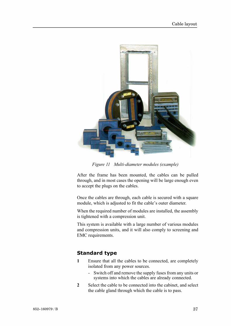
Cable layout
37852--160979 / B
Figure 11 Multi-diameter modules (example)
After the frame has been mounted, the cables can be pulledthrough, and in most cases the opening will be large enough evento accept the plugs on the cables.
Once the cables are through, each cable is secured with a squaremodule, which is adjusted to fit the cable’s outer diameter.
When the required number of modules are installed, the assemblyis tightened with a compression unit.
This system is available with a large number of various modulesand compression units, and it will also comply to screening andEMC requirements.
Standard type
1 Ensure that all the cables to be connected, are completelyisolated from any power sources.- Switch off and remove the supply fuses from any units orsystems into which the cables are already connected.
2 Select the cable to be connected into the cabinet, and selectthe cable gland through which the cable is to pass.

Kongsberg Simrad EM 1002 / Base version & Hull Unit
38 852--160979 / B
Figure 12 Multi-diameter system- Principal procedure
Figure 13 Multi-diameter system -The finishied assembly
3 Slacken and remove the compression nut from the cablegland, and extract the compression seal and the screen collarfrom the body of the gland.

Cable layout
39852--160979 / B
Figure 14 Standard cable gland assembly
Compression nut
Cable
Gland body Cabinet panel
Screen collarCompression seal
Screen
(CD3260)
Note Aminimum of 5 cm (recommended 5 - 10 cm) of slack cable mustbe allowed, both inside and outside the cabinet, when installingcables. This is to allow for vibration damping, maintenance andmeasurement errors. Always double-check your measurementsbefore taking any irreversible actions.
4 Depending on whether the cable has already been installedin conduits, either:c (installed) measure the maximum length of cablerequired to reach from the final cable clip outside thecabinet to the terminal blocks inside the cabinet, add 20cm, then remove the excess cable,
or:d (loose cable) measure the maximum length of wirerequired to reach from the cable gland to the terminalblocks inside the cabinet, add 20 cm. and mark the cable.
Note The cable’s outer insulation will extend into the cable gland to apoint approximately 5 mm outside the outer surface of the cabinetwall into which the cable gland is secured.
5 Taking care not to damage the screening, carefully removethe outer insulation from the required cable length.
6 Leaving 12 mm of the screen exposed from the insulation,cut off the remainder.
7 Taking care not to damage the screening, slide thecompression nut (smallest diameter first) over the cable andonto the intact insulation.
8 Taking care not to damage the screening, slide thecompression seal (rounded end first) over the cable and ontothe intact insulation.

Kongsberg Simrad EM 1002 / Base version & Hull Unit
40 852--160979 / B
9 Slide the screen collar (narrow end first) onto the cable andfit it underneath the screen. Slide it as close to the intact outerinsulation as possible.
10 If the screen extends beyond the “flat” end of the screencollar, fold any excess length over the end of the collar suchthat the screen will be gripped between the collar and thegland body when the parts are assembled.
11 Carefully thread the cable through the gland body till thescreen collar is tight into the gland body.
12 Slide the compression seal into the gland body till theshoulder is hard up against the gland body.
13 Slide the compression nut over the compression seal andengage the threads.
14 While holding the gland body to prevent it turning, andpressing the cable into the gland, tighten the compressionnutonto the gland body.
15 Referring to the wiring diagram and ensuring that there is 5to 10 cm. slack cable inside the cabinet, prepare and connectthe cable cores to the appropriate terminals within thecabinet.
16 Secure the cable within the cabinet using cable clips.17 Check the terminal connections against the wiring diagram
to ensure they are correct.Follow the same procedure for all the cables and cable glands.Once all the cables have been fitted:18 Check the cabinet to ensure all tools and rubbish are
removed, then close the cabinet door.Once all the system cables are connected and checked:19 Take the appropriate safety measures, then replace the fuses
and apply power to the system.20 Perform a system test to ensure the installation has been
conducted successfully.
Additional type 1 (842-093878)1 Mount the cable gland body, and tighten it with the nuts on
each side of the cabinet wall.2 Slide the metal washers, the rubber gasket and the
compression nut onto the cable in the order indicated in thefigure.
→ Refer to figure 15.

Cable layout
41852--160979 / B
Rubber gasket
Metal washer
Cable gland body
Compression nut
Cabinet wall
Inner cable
Outer screen bend backwardsover the rubber gasket
Cable
Metal washer
(CD3685/093878)
Figure 15 Cable gland, type 1(842-093878)
3 Bend the screen over the rubber gasket.4 Push the rubber gasket and the two metal washers carefully
into the cable gland body.5 While holding the gland body to prevent it turning, and
pressing the cable into the gland, tighten the compressionnutonto the gland body.
Additional type 2 (541-093642)1 Mount the cable gland body, and tighten it with the nuts on
each side of the cabinet wall.2 Slide the metal washers, the rubber gasket and the
compression nut onto the cable in the order indicated in thefigure.
→ Refer to figure 16.
3 Bend the screen over the compression cone.4 Push the compression conne, the washers and the rubber
sealing washer into the cable gland body.5 Close the mounting nut.6 Close and tighten the compressionnut on the other side of the
cabinet wall.

Kongsberg Simrad EM 1002 / Base version & Hull Unit
42 852--160979 / B
(CD3765/093642)
Compression cone Rubber sealing
Metal washersFemale compression cone
Compression nut
Mounting nut
Cable gland body
Figure 16 Cable gland, type 2(541-093642)

Cable layout
43852--160979 / B
3.6 Cable specifications
IntroductionThe next pages provide detailed information about the cables usedon the system. Note that several cables may share identicalspecifications.
The technical parameters provided for the cables are theminimumspecifications. Also, in most cases, it may be useful to install extrapairs in selected cables for future expansions.
Note The cables specified may not meet the standards provided by thevessel’s classifiaction society. Consult the applicable guidelines.
Kongsberg Simrad as takes no responsibility for damage caused tosystem, vessel or personnel if the cables used during installation donot meet these specifications.

Kongsberg Simrad EM 1002 / Base version & Hull Unit
44 852--160979 / B
3.7 Basic cabling requirements
Cable trays
All permanently installed cables associated with the system mustbe supported and protected along their entire lengths usingconduits and/or cable trays. The only exception to this rule is overthe final short distance (max. 0.5 metre) as the cables run into thecabinets/units to which they are connected. These shortunsupported lengths are to allow the cabinets to move on theirshock mounts, and to allow maintenance and replacements.
• Wherever possible, cable trays must be straight, accessible andplaced so as to avoid possible contamination by condensationand dripping liquids (oil, etc.). They must be installed remotefrom sources of heat, and must be protected against physicaldamage. Suitable shields must be provided where cables areinstalled in the vicinity of heat sources.
• Unless it is absolutely unavoidable, cables should not beinstalled across the vessel’s expansion joints. If the situation isunavoidable, a loop of cable having a length proportional to thepossible expansion of the jointmust be provided. Theminimuminternal radius of the loop must be at least twelve times theexternal diameter of the cable.
• Where a service requires duplicate supply lines, the cablesmustfollow separate paths through the vessel whenever possible.
• Signal cables must not be installed in the same cable tray orconduit as high-power cables.
• Cables containing insulation materials with differentmaximum-rated conductor temperatures should not be bunchedtogether (that is, in a common clip, gland, conduit or duct).When this is impractical, the cables must be carefully bunchedsuch that themaximum temperature expected in any cable in thebunch is within the specifications of the lowest-rated cable.
• Cables with protective coverings which may damage othercables should not be bunched together with other cables.
• Cables having a copper sheath or braiding must be installed insuch a way that galvanic corrosion by contact with other metalsis prevented.
• To allow for future expansion of the system, all cables shouldbe allocated spare conductor pairs.Also, spacewithin the vesselshould be set aside for the installation of extra cables.

Cable layout
45852--160979 / B
Radio Frequency interference
All cables that are to be permanently installed within 9 m (30 ft)of any source of Radio Frequency (RF) interference such as atransmitter aerial system or radio cabin, must, unless shielded bya metal deck or bulkhead, be adequately screened by sheathing,braiding or other suitable material. In such a situation flexiblecables should be screened wherever possible.
It is important that cables, other than those supplying services tothe equipment installed in a radio room, are not installed througha radio room. Cables which must pass through a radio room mustbe screened by a continuous metal conduit or trunking whichmustbe bonded to the screening of the radio room at its points of entryand exit.
Physical protection
Cables exposed to the risk of physical damagemust be enclosed ina steel conduit or protected by a metal casing unless the cable’scovering (e.g. armour or sheath) is sufficient to protect it from thedamage risk.
Cables exposed to an exceptional risk of mechanical damage (forexample in holds, storage-spaces and cargo-spaces) must beprotected by a suitable casing or conduit, even when armoured, ifthe cable covering does not guarantee sufficient protection for thecables.
Metallic materials used for the physical protection of cables mustbe suitably protected against corrosion.
Grounding
All metallic cable coverings (armour, lead sheath etc.) must beelectrically connected to the vessel’s hull at both ends except in thecase of final sub-circuits where they should be connected at thesupply end only.
Grounding connections should be made using a conductor whichhas a cross-sectional area related to the current rating of the cable,or with a metal clamp which grips the metallic covering of thecable and is bonded to the hull of the vessel. These cable coveringsmay also be grounded by means of glands specially intended forthis purpose and designed to ensure a good earth connection. Theglands used must be firmly attached to, and in good electricalcontact with, a metal structure grounded in accordance with theserecommendations.

Kongsberg Simrad EM 1002 / Base version & Hull Unit
46 852--160979 / B
Electrical continuity must be ensured along the entire length of allcable coverings, particularly at joints and tappings. In no caseshould the lead-sheathing of cables be used as the only means ofgrounding cables or units.
Metallic casings, pipes and conduits must be grounded, and whenfitted with joints these must be mechanically and electricallygrounded.
Cable connectionsAll cable connections are shown on the applicable cable plan andinterconnection diagrams.
Where the cable plan shows cable connections outside anequipment box outline, the connections are to be made to a plug orsocket which suits the plug or socket on that particular item ofequipment.
Where two cables are connected in series via a junction box orterminal block, the screens of both cables must be connectedtogether but not grounded.
Cable terminationsCare must be taken to ensure that the correct terminations are usedfor all cable conductors, especially those that are to be connectedto terminal blocks. In this case, crimped sleeve-terminations mustbe fitted to prevent the conductor core from fraying and making abad connection with the terminal block. It is also of the utmostimportance that where crimped terminations are used, the correctsize of crimp and crimping tool are used. In addition, each cableconductor must have a minimum of 15 cm slack (service loop) leftbefore its termination is fitted.
Cable identificationCable identification codes corresponding to the cable numbershown in the cable plan must be attached to each of the externalcables. These identification codes should be positioned on thecable in such away that they are readily visible after all panels havebeen fitted. In addition, each cable conductor should be markedwith the terminal board number or socket to which it is connected.

Cable layout
47852--160979 / B
Generic RS-232 serial line (DTE)This cable described the pin configuration for an RS-232 interface.The Data Terminal Equipment (DTE) end is shown.The DTE end is shown on page 48.
W101 / Rev. B RS-232 serial line (DTE)
14
4
11
1
18
8
16
6
13
3
15
5
12
2
19
9
202122232425
10
Original and complete RS-232 signaldefinition shown. The most commonlyused signals are shown in bold.
(DTE = Data Terminal Equipment)
17
7
25-pin D-sub connector
Looking into a male 25-pin D-pin connector2514
1 13
ShieldTransmitted data (Tx)
Received data (Rx)Request to send (RTS)
Clear to send (CTS)DCE Ready
Signal groundRx line signal detectReserved for testingReserved for testing
UnassignedSec. Rx line signal detect
Sec. Clear to sendSec. Tx data
Transmitter signal timingSec. Rx data
Rx signal timing (DCE source)Local loopback
Sec. Request to sendDTE Ready
Remote loopbackRing indicator
Data signal rate selectorTx signal timing (DCE Source)
Test mode
Conductors XX x 2 x 0.5 mm2
Screen Overall braided
Voltage 60 V
Max.diameter Set by the plugs

Kongsberg Simrad EM 1002 / Base version & Hull Unit
48 852--160979 / B
Generic RS-232 serial line (DCE)This cable described the pin configuration for an RS-232 interface.The Data Circuit terminating Equipment (DCE) end is shown.The DTE end is shown on page 47.
W102 / Rev. B RS-232 serial line (DCE )
14
4
11
1
18
8
16
6
13
3
15
5
12
2
19
9
202122232425
10
Original and complete RS-232 signaldefinition shown. The most commonlyused signals are shown in bold.
(DCE = Data Circuit terminating equipment)
17
7
25-pin D-sub connector
Looking into a female 25-pin D-pin connector1425
13 1
ShieldReceived data (Rx)
Transmitted data (Tx)Clear to send (CTS)
Request to send (RTS)DCE Ready
Signal groundReceived line signal detect
Reserved for testingReserved for testing
UnassignedSec. Rx line signal detect
Sec. Request to sendSec. Rx data
Transmitter signal timingSec. Tx data
Rx signal timing (DCE source)Local loopback
Sec. Clear to sendDTE Ready
Remote loopbackRing indicator
Data signal rate selectorTx signal timing (DTE Source)
Test mode
Conductors XX x 2 x 0.5 mm2
Screen Overall braided
Voltage 60V
Max.diameter Set by the plugs

Cable layout
49852--160979 / B
Generic RS-232 Serial lineThis cable comprises a multi-purpose serial line. It providesinterface with any peripheral unit. One end of the cable connectsto the local unit (DTE) with a 9-pin ’D’ connector, while the otherconnects to the peripheral (DCE) as described in the peripheralunit’s documentation.Note that this cable does not support all the signals in the standardRS-232 specification.
W103 / Rev G Standard RS-232 serial line
235
RxTx
Ground
View
Local (DTE) 9-pin‘D’ connector
Remote unit (DCE) tobe connected as describedin applicable documentation
Looking intofemale 9-pin
D-pin connector
5 1
69
Looking intomale 9-pin
D-pin connector
1 5
96
Screen
To plug housing
Conductors 3 x 2 x 0.5 mm2
Screen Overall braided
Voltage 60V
Max.diameter Set by the plugs

Kongsberg Simrad EM 1002 / Base version & Hull Unit
50 852--160979 / B
Generic coax cableThis cable is used for connections to peripheral units or networks.
In the EM 1002, EM 120 and EM300 systems, this cable connectsthe 1 PPS timing signal to the Transceiver Unit. It is also possibleto use a coax connection between the Transceiver Unit and theOperator Station.
W105 / Rev.D Coax connection to peripheral unit or network
LiveGnd
LiveGround
LocalCoax connector
Peripheral unit tobe connected as describedin applicable documentation
Live
Screen/Ground

Cable layout
51852--160979 / B
Serial line to Hull Unit ControllerThis serial line provides the control signals between theTransceiver Unit and the Hull Unit Controller. Each end of thecable is terminated in a standard female 9-pin ’D’ connector.
W109 / Rev.B Transceiver Unit - Hull Unit Controller
2
53
TXDARXDAGround
2
53
Hull Unit Controller9-pin ‘D’ connector
Female plug, front view
Male socket, seen from below
Transceiver Unit‘Hull Unit’ connector
9-pin D-connector, male 9-pin D-connector, male
2 53
Conductors 3 x 2 x 0.5 mm2
Screen Overall braided
Voltage 60V
Max.diameter Set by the plugs

Kongsberg Simrad EM 1002 / Base version & Hull Unit
52 852--160979 / B
On/off from Hull Unit ControllerThis cable provides remote control of the Transceiver Unit power.A female 9-pin ’D’ connector is used on the cable’s TransceiverUnit end, while the other end is connected to the Hull UnitController’s terminal block.When the “On” switch on the RemoteControl Unit is pushed, power is applied to the Hull UnitController, and then through this cable to the Transceiver Unit.
W110 / Rev.B Transceiver Unit - Hull Unit Controller
1011
StandbyOn
45
Hull Unit ControllerTRTB1
Transceiver Unit9-pin ‘D’ connector ‘Remote’
Male socket, seen from below
2 53
9-pin D-connector, male
Female plug, front view
Conductors 3 x 2 x 0.5 mm2
Screen Overall braided
Voltage 60V
Max.diameter Set by the plugs

Cable layout
53852--160979 / B
Sound speed probe interfaceThis cable provides the interconnection between the ProcessorUnit work station and the sound speed probe. This connection isnormally made through a small junction box and with a powersupply as indicated in the drawing.
W119 / Rev.B Sound speed probe interface
Male25-pin D-connector
8 - 16 Vdc
AC Power
(W301)
Tx
Rx
Ground
2
1
5432
34
Male 25-pinD-pin connector
14 25
131
1:1 Junction box
Probe
Work Station
Powersupply
View
The cable between the junction box and the probe is supplied bythe probe manufacturer.
Conductors 2 x 2 x 0.5 mm2
Screen Overall braided
Voltage 60V
Max.diameter Set by the plugs

Kongsberg Simrad EM 1002 / Base version & Hull Unit
54 852--160979 / B
EM Remote synchronisation and On/OffThis cable connects theTransceiver Unit to a remoteOn/Off switchlocated in a Junction Box (type EM1-212595). The sameconnection allows trigger output and remote control(synchronisation) with a serial line.
W202 / Rev C Transceiver Unit - Junction Box
1
32
45
76
899
9
1
1
3
3
2
2
4
4
5
5
7
7
6
6
8
8
Junction box EM1-212595Terminal block
Trigger out
Trigger out
Trigger GND
Trigger GND
Standby +
Standby -
On
RTS
RTS
CTS
CTS
GND
GND
(Not connected)
Transceiver Unit9-pin ‘D’ connector
‘Remote’
Trigger out toexternal system(synchronisation)
Serial line to/fromexternal system (synchronisation)
Junction box EM1-212595
System On/Off
Conductors 5 x 2 x 0.5 mm2
Screen Overall braided
Voltage 60V
Max.diameter Set by the plugs

Cable layout
55852--160979 / B
EM Remote Control with 3 switchesThis cable connects theTransceiver Unit to a remoteOn/Off switchlocated in a JunctionBox (type 108-215397). The sameconnectionallows trigger output and remote control (synchronization) with aserial line.
W238 / Rev A Transceiver Unit - Junction Box
1
32
45
76
8929
29
21
21
23
23
22
22
24
24
25
25
27
27
26
26
28
28
Junction box 108-215398Terminal block
Trigger out
Trigger out
Trigger GND
Trigger GND
Standby +
Standby -
On
RTS
RTS
CTS
CTS
GND
GND
(Not connected)
Transceiver Unit9-pin ‘D’ connector
‘Remote’
Trigger out toexternal system(synchronisation)
Serial line to/fromexternal system (synchronisation)
Junction box 108-215398
System On/Off
Conductors 5 x 2 x 0.5 mm2
Screen Overall braided
Voltage 60V
Max.diameter Set by the plugs

Kongsberg Simrad EM 1002 / Base version & Hull Unit
56 852--160979 / B
Standard AC power cableThis cable is a standard three-wire power cable. It is commerciallyavailable in standard lengths, ormay be produced locally to suit thespecific installation needs. The instrument end is terminated in astandard IEC female socket, while the other end is terminated ina plug suitable for the local standard.
W301 / Rev B Standard power cable for 115/230 Vac 2-phase
Live (normally Blue)
Neutral (normally Brown)
Use the applicable plug to suitlocal standard. British standardplug used as example only.
Ground (always Yellow or Yellow/Green)
IEC plug
Note Different cable colours may be used for the “live” and “neutral”wires. Ground is however always on green/yellow.
Conductors 2 x 1.5 mm2 + GND
Screen None
Voltage 750 V
Max. diameter Set by the plugs

Cable layout
57852--160979 / B
3-phase AC power to Relay UnitThis cable connects 230 or 380 Vac 3-phase to the EM 1002 RelayUnit.
W304 / Rev.A AC 3-phase power to Relay Unit
456
230/380 Vac3 phase
Ground
Relay UnitE502
Conductors 3 x 1.5 mm2 + Gnd
Screen Seperate conductor
Voltage 750V
Max.diameter 20 mm

Kongsberg Simrad EM 1002 / Base version & Hull Unit
58 852--160979 / B
3-phase AC power to hoist motor
This cable connects the 3-phase power from the Relay Unit and tothe hull unit’s hoist motor. Note that the cable can be connected intwo ways, depending on the motor’s voltage requirements.
Note The hoist motor used after June 1999 requires an external +24Vdcto operate. This change is implemented from hull unit with serialnumber 211.
W305B / Rev.A AC 3-phase power to hoist motor (Serial no => 211)
123
Relay UnitE502
or...
Motor brake
Motor brake
Hoist motor (440/380 Vac)
Internal cable
Hoist motor (230 Vac)
R
RR
T
T 440 Vac / 60 Hz380 Vac / 50 Hz
230 Vac / 50 Hz
T
S
SS
3433
Hull UnitE401
+24 Vdc
GND
Important notice!This configuration is usedon hull units from and includingserial no.211.
U
V
Z
X
YW
U
V
Z
X
YW
U
V
Z
X
YW

Cable layout
59852--160979 / B
W305 / Rev.B AC 3-phase power to hoist motor (Serial no < 211)
123
Relay UnitE502
Motor brake
Motor brake
Hoist motor (440/380 Vac)
Hoist motor (230 Vac)
R
R
R
T
T 440 Vac / 60 Hz380 Vac / 50 Hz
230 Vac / 50 Hz
T
S
S
S
Important notice!This configuration was usedon hull units prior to serialno.211.
U
V
Z
XY
W
U
V
Z
X
YW
or...

Kongsberg Simrad EM 1002 / Base version & Hull Unit
60 852--160979 / B
3-phase AC power to Hull Unit ControllerThis cable connects 230 or 380 Vac 3-phase to the Hull UnitController.
W306 / Rev.A AC 3-phase power to Hull Unit Controller
246
230/380 Vac3 phase
Ground
Hull Unit ControllerTRTB8
Conductors 3 x 1.5 mm2 + Gnd
Screen Seperate conductor
Voltage 750V
Max.diameter 20 mm

Cable layout
61852--160979 / B
Ethernet with RJ45This cable contains the Ethernet connection. RJ45 plugs are usedto terminate the cable. Note that these plugs must be screened tocomply to EC rules.
W400 / Rev D Ethernet 10Base-T with RJ45 plugs
1
1
3
3
2
2
4
4
5
5
7
7
6
6
8
8
1
1
3
3
2
2
4
4
5
5
7
7
6
6
8
8
RJ45 plug
RJ45 plug
RJ45 plug
Ethernet 10Base-T “Straight Through”
Ethernet 10Base-T “Crossover”(Used to cascade HUBs, or for connecting two
ethernet stations or computers back-to-back without a HUB)
TX Data + (White/Orange)
(1) TX Data + to (3) Recv Data +
Tx Data - (Orange)
(2) Tx Data - to (6) Recv Data -
Recv Data + (White/Green)
(3) Recv Data + to (1) Tx Data +
(Blue)
(White/Blue)
Recv Data - (Green)
(6) Recv Data - to (2) Tx Data -
(White/Brown)
(Brown)
RJ45 plug
Pin 8
Pin 8
View
Pin 1
Pin 1

Kongsberg Simrad EM 1002 / Base version & Hull Unit
62 852--160979 / B
VGA Display cableThis is a standard display cable used to connect the video signals.Depending on the computer type, the cable may be terminated in:• Standard VGA plug (typical on most commercial computers)
• Multiconnector for Unix work stations• Seperate RGB connectors (used on high-quality monitors)
The cable is normally physically fastened to the display unit, andit is provided with the plug(s) readily attached.
W502 / Rev B Display Unit
15-pin ‘D’ connector(VGA type)
Multi-connectorfor Unix work stations
Seperate R, G and B connectors(used with monitors)

Cable layout
63852--160979 / B
Keyboard cableThis is a standard keyboard cable. In most cases, the cable isphysically connected to the keyboard. It is terminated in a plugsuited to fit the computer.Several keyboard types are available for different languages andhardware platforms. Both the keyboard and the attached cable arecommercial items.
W503 / Rev C Keyboard
Keyboard(Different keyboard types are supplied)
In most cases, the keyboardcable is physically connected
to the computer
Plug suited for the computer

Kongsberg Simrad EM 1002 / Base version & Hull Unit
64 852--160979 / B
Mouse or pointing device cableThis is a standard mouse cable. It is physically connected to themouse. It is terminated in a plug suited to fit the computer.
Note On Unix work stations, the mouse is normally connected to thekeyboard.
Several mouse and pointing device types are available with two orthree buttons, and with or without a scroll wheel. Both the mouseand the attached cable are commercial items.
W504 / Rev B Mouse / Pointing device
Mouse(Different mouse types and other pointing devices are supplied)
The cable is physically connectedto the mouse
Plug suited for the computer
Note that certain mouse typesfor Unix work stationsare connected to the keyboard.
Various mouse types support twoor three buttons, and may also
provide a scroll wheel.

Cable layout
65852--160979 / B
Centronics printer cableThis is a standard Centronics printer cable.
W505 / Rev C Centronics printer cable
1
32
45
76
89
1110
1518-24
StrobeData 0Data 1Data 2Data 3Data 4Data 5Data 6Data 7AcknowledgeBusyErrorGround
Printerplug
25-pinD-connector
25 14
113The socket on the rearside of the computeris normally a 25-pin femaleD-connector.

Kongsberg Simrad EM 1002 / Base version & Hull Unit
66 852--160979 / B
Local Control UnitThis cable connects the EM 1002 Relay Unit to the Local ControlUnit.
W601 / Rev.A Relay Unit - Local Control Unit
1
32
45
76
89
1110
121314
21
2322
2425
2726
2829
3130
3233
BL BLWH WHO OWH WHGN GNWH WHBN BNWH WHGR GRWH WHBL BLR RO OR R
Local Control UnitE1
Relay UnitE501
Conductors 2 x 7 x 0.5 mm2
Screen Overall braided
Voltage 60V
Max.diameter 20 mm

Cable layout
67852--160979 / B
Remote Control UnitThis cable connects the Relay Unit to the Remote Control Unit.
W602 / Rev.A Relay Unit - Remote Control Unit
1
32
45
76
89
1110
121314
4
65
78
109
1112
1413
151617
BL BLWH WHO OWH WHGN GNWH WHBN BNWH WHGR GRWH WHBL BLR RO OR R
Relay UnitE501
Remote Control UnitE1
Conductors 2 x 7 x 0.5 mm2
Screen Overall braided
Voltage 60V
Max.diameter 20 mm

Kongsberg Simrad EM 1002 / Base version & Hull Unit
68 852--160979 / B
Relay Unit controlThis cable supplies control signals between the Relay Unit and theHull Unit Controller.UP - this signal is active lowwhen you have pressed theUp buttonon the Remote or Local Control Unit.
TD OUT - this signal is active high when the lower limit switchreports the transducer array to be fully lowered.+24 Vdc - This voltage is supplied by the Relay Unit when the“On” switch on the Remote Control Unit has been pushed. Thecontrol voltage powers up the Hull Unit Controller.
W603 / Rev.A Relay Unit - Hull Unit Controller
12
2
1011
1
9
36
UP reference (DGND)UP
Ground
Ground
Ground
+24 Vdc
TD OUT
TD OUT
8
3135
9
26
Relay UnitE502
Relay UnitE501
Hull Unit ControllerTRTB2
Hull Unit ControllerTRTB1
Conductors 4 x 2 x 0.5 mm2
Screen Overall braided
Voltage 60V
Max.diameter 15 mm

Cable layout
69852--160979 / B
Limit switches and hoist motor brake
This cable supplies control signals from the upper and lower limitswitches between the EM 1002 Hull Unit termination block E401and the Relay Unit. The drawing also shows how the variousswitches are connected to termination block E401.
LLS - Lower Limit Switch. The control line is active lowwhen theswitch is closed (transducer array lowered to maximum position.
ULS - Upper Limit Switch. The control line is active lowwhen theswitch is closed (transducer array hoisted to maximum position).
24Vx - The PitchCenter Switch isonly closedwhen the transducerarray is level. The 24 Vx line is then closed, and hoisting can takeplace.
+24 Vdc (Hoist motor brake) - The voltage on this line enablesthe hoistmotor brake. Note that this connection is onlyused onhullunits with serial number 211 or higher.
W604 / Rev.C Relay Unit - Hull Unit
20
20
9
9
21
21
1
8
22
23
1
23
8
119
3
4 342
20 33
Relay UnitE501
Hull UnitE401
Hull UnitE401
24 V1
+24 Vdc (Hoist motor brake)Ground (Hoist motor brake)
24 V2LLSULS
Ground
Pitch centerswitch
Lower Limitswitch
Upper Limitswitch
Crankswitch

Kongsberg Simrad EM 1002 / Base version & Hull Unit
70 852--160979 / B
Conductors 2 x 7 x 0.5 mm2
Screen Overall braided
Voltage 60V
Max.diameter 20 mm

Cable layout
71852--160979 / B
Synchro feedbackThis cable provides feedback from the synchro monitoring thepitch motor.BS1 - Synchro signal phase 1
BS2 -Synchro signal phase 2BS3 -Synchro signal phase 3
BREF - Synchro reference
W605 / Rev. A Hull Unit Controller - Hull Unit
2
43
56
1
32
45
Hull Unit ControllerTRTB2
Hull UnitE401
BS1BS2BS3
BREF+BREF-
Conductors 5 x 1.5 mm2
Screen Overall braided
Voltage 750V
Max.diameter 20 mm

Kongsberg Simrad EM 1002 / Base version & Hull Unit
72 852--160979 / B
Pitch motor powerThis cable provides the power lines for the pitchmotor. Themotoris controlled by a DC voltage with a duty cycle controlling bothmotor speed and direction. 50% duty cycle brings themotor to fullstop.
W606 / Rev.A Hull Unit Controller - Hull Unit
1718
34
Hull Unit ControllerTRTB1
Hull UnitE401
DC M-DC M+
Conductors 3 x 2.5 mm2
Screen Overall braided
Voltage 750V
Max.diameter 20 mm
The feedback from the pitch motor are identified as Tacho+ andTacho- on a different cable.→ Refer to page 73.

Cable layout
73852--160979 / B
Pitch limit and speed informationThis cable provides the control signals from the pitch limitswitches (positive and negative) as well as the speed informationfrom the pitch motor.Speed EN - Two switches are implemented to stop the pitchmovement if it exceeds the outer limits defined by the software. Ifone of the two switches is opened, the pitch movement will stopaltogether, and you need to use the service switch in the Hull UnitController to restart it.Tacho - Speed information from the pitch motor.
W607 / Rev.A Hull Unit Controller - Hull Unit
14
1615
1113
6
75
89
Hull Unit ControllerTRTB1
Hull UnitE401
Tacho -Tacho +
Speed EN1Speed EN2
1113
Hull UnitE401
Pitch limitnegative
Pitch limitpositive
Service switch inHull Unit Controller
Conductors 2 x 2 x 0.5 mm2
Screen Overall braided
Voltage 60V
Max.diameter 15 mm

Kongsberg Simrad EM 1002 / Base version & Hull Unit
74 852--160979 / B
EM 1002 synchronizationThis cable provides the control signals between the EM 1002Multibeam Echo Sounder and the Synchronization Unit.
W722 / Rev. C Synchronization Unit - EM 1002
Trigger monitor
Ready for next trigger
GND
TriggerEM 1002
Remote,DB-9 female10 kohm
1 kohm
SSU SSUSensorbus
Junction boxterminal block
+12 VCTS
RTS
Trig outTrig ref
-12 VOutput ch 3 -
Input ch 3 +
Input ch 4 +
Input ch 3 -
GND
Input ch 4 -
Output ch 3 + 7
1
6
29
11
10
4029
12
21
2
30
Conductors 6 x 2 x 0.25 mm2
Screen Overall braided
Voltage 60V
Max. diameter Set by the plugs

Design and mode of operation
75852-160979 / B
4 TRANSCEIVER UNIT
4.1 Description and main functions
OverviewThe EM 1002 Transceiver Unit performs the reception, dataacquisition, received signal processing and transmission for themultibeam echo sounder system. The cabinet holds two wiredracks containing the system circuit boards.
• The top Processing Rack holds the complete Processing Unitwith its own power supply. This unit provides data acquisition,signal processing and function control.
• The bottom Receiver Rack holds the receiver and transmitterboards, a controller, two power supplies and a large capacitorbank.
This chapter provides the following information:→ Description and main functions, page 75.→ Transceiver Unit outline, page 76.→ Theory of operation, page 82.→ Processing rack, details, page 87→ Receiver rack, details, page 88.→ Circuit board descriptions, page 89.

Kongsberg Simrad EM 1002 / Base version & Hull Unit
76 852--160979 / B
Figure 17 Transceiver Unit, dimensions
600 mm
670mm
min
290
A
A-A
A
A
A
975
mm
8383
260 mm
83
0
190
330
11
520
1110
mm
(CD
4527
D /
830-
2117
50 /
A)

Design and mode of operation
77852--160979 / B
RX
RX
INT
2
RX
INT
1
(CD5793B/861-211813AD)
Figure 18 Wired Cabinet. Subassembly, Transceiver Unit

Kongsberg Simrad EM 1002 / Base version & Hull Unit
78 852--160979 / B
TRB
1-P
2
TRB
2-P
2
TRB
3-P
2
TRB
4-P
2
TRB
1-P
5
TR
B3-
P5
TRB
2-P
5
TRB
4-P
5
(CD5794B/211813BD)
Figure 19 Wired rack, Transceiver Unit

Design and mode of operation
79852--160979 / B
The Processing RackThe Processing Rack is located at the top of the Transceiver Unit.It holds a chassis with several circuit boards, a fan and a powersupply. A ground strap and a circuit breaker for the power supplyis also available, but these are mounted on the main rack, and noton the shelf.
(CD5794C/211813BD)
ROM Card Processor Card BSP1
BSP2Ethernet CardSerial Card
Slot 7
Slot 8
Slot 5
Slot 10
Slot 3
Slot 4
Slot 6
Slot 1
Slot 2
4 7 81 27 8654321
P8
3 65
P9
3 421

Kongsberg Simrad EM 1002 / Base version & Hull Unit
80 852--160979 / B
The Processing Rack holds the following circuit boards andmodules:• 4-Ports Serial Line boardThe different versions of the EM 1002 has different serial lineboards:- Transceiver Unit with Reg.no. 125-211815: C114P- Transceiver Unit with Reg.no. 125-218141: CI-104JS
• Beamformer & Signal Processor (BSP1 and BSP2)• Ethernet Adapter- The ethernet board has been replaced with an ethernetconnection on the CPU board.
• ROM boardOn newer systems, made after summer 2001, the ROM boardhas been replaced with a DiskOnModule flash disk mountedon the Control Processing Unit board. The ROM board willbe replaced on older systems too.
• Control Processing Unit boardThe different versions of the EM 1002 Transceiver Unit hasdifferent CPU boards:- Transceiver Unit with Reg.no. 125-211815:SSC-486H / SSC-5x86H
- Transceiver Unit with Reg.no. 125-218141:VIPer 629
• Power supply• Fan
• Motherboard→ A more detailed description of all the circuit boards and modules
is found on page 87.

Design and mode of operation
81852-160979 / B
The Receiver RackTheReceiver Rack is located at the bottomof theTransceiver Unit.It holds several circuit boards, power supplies and a capacitorbank. All the units are accessed from the front of the rack.
Capacitor U
nit 299-211671
SPR
X 382-211651
HV-Pow
er Unit 290-112751
Power S
upply 290-214082
TRB4 382-211041
TRB3 382-211041
TRB2 382-211041
TRB1 382-211041
SIMRADHV-POWER UNIT 290-112751
KONGSBERG SIMRADPOWER SUPPLY 290-214082
HIGHMIDDLELOWf (SW)
L207
F206
L206
F2058ASLOW
BLOW
L205
S203230 V ac
Caution!Do not pull out this unitbefore the meter showszero (0) voltage.For continued protectionagainst risk of firereplace only with sametype and rating of fuse.
S203230 V ac
F2018A
F2028ASLOW
BLOW
S201230 V ac
Mains input115/230 V ac
P201
L201
L202
S202SERVICEOFF
NORMAL
L203
L204
F203
Powersupply24 V
Analogpowersupply+-8 V
(CD
5779B/860-211815)
Fan drawer
High Voltagepower supply
Low Voltagepower SupplyTransmitter/Receiver Boards Capacitor bank
Signal Processor Board (SPRX)
Figure 20 The Receiver Rack
The Receiver Rack holds the following circuit boards andmodules(from left):• TRB 32/Receiver/Transmitter board (x 4)
• Low Voltage Power Supply• High Voltage Power Supply
• Signal Processor Board RX (SPRX)• Capacitor bank→ A more detailed description is found on page 88.

Kongsberg Simrad EM 1002 / Base version & Hull Unit
82 852-160979 / B
4.2 Theory of operation
OverviewThis chapter presents a functional description of the TransceiverUnit.
Simplified block diagramThe simplified block diagram for theTransceiver Unit presents the followingmain functions:• Transmission
• Reception• Processing
The various parameter settings made on theOperator Station are sent to the ControlProcessor in the Processing Rack. Theinformation is interpreted, and passed on tothe Signal Processor RX (SPRX) in theReceiver Rack.After the transmission, the Signal ProcessorRX (SPRX) receive the echoes, and passthem to the two Beamformer and SignalProcessors (BSP) in the Processing Rack.
Figure 21 Transceiver Unit,simplified block diagram
Control Processor
Beamformer and SignalProcessor (BSP) x 2
Signal Processor Rx(SPRX)
Seria
l lin
es to
/from
the
sens
ors
Ethernet to/from theOperator Station
Com
man
d an
dco
ntro
l (se
rial l
ine)
16-bitsampleddata
Processing Rack
Receiver Rack
Receiver/TransmitterBoard (TRB) x 4
Receive/Transmit array
(CD5766)

Design and mode of operation
83852-160979 / B
Control functionsThe control functions in the Transceiver Unit are mainly handledby the two processor boards, but additional peripheral boards arealso used. The majority of the control boards are contained in theProcessing Rack.
Note Three different versions of the Transceiver Unit exist. To find outwhich one you have, find the reg.no. on your cabinet.
Reg.no. 125-211815 (with PROM)
The Control Processor in the Processing Unit is not equipped withinterface capabilities, and thus requires external boards to handleethernet and serial lines interface. It also relies on an externalmemory board for the software contained in the ROM device. Allthe peripheral boards used here are commercial.
Figure 22 The control functions for 125-211815 with PROM
Seriallines
PROM bank Controlprocessor
Ethernetadapter
BSP x 2
Signal Processor Rx(SPRX)
Command andcontrol (serial line)
Processing Rack
Receive/Transmit circuitry
Bus system
(CD5769)

Kongsberg Simrad EM 1002 / Base version & Hull Unit
84 852-160979 / B
Reg.no. 125-211815 (without PROM)The Control Processor in the Processing Unit is not equipped withinterface capabilities, and thus requires external boards to handleethernet and serial lines interface.
Reg.no. 125-218141The Control Processor in the Processing Unit is equipped withinterface capabilities and a DOM (Disk On Module) flash disk.
Figure 24 The control functions for 125-218141
Seriallines
Controlprocessor BSP x 2
Signal Processor Rx(SPRX)
Serial lines to/fromthe sensors
Ethernet to/from theOperator Station
Command andcontrol (serial line)
Processing Rack
Receive/Transmit circuitry
Bus system
(CD5769 )-3
Figure 23 The control functions for 125-211815 without PROM
Seriallines
Controlprocessor
Ethernetadapter
BSP x 2
Signal Processor Rx(SPRX)
Serial lines to/fromthe sensors
Ethernet to/from theOperator Station
Command andcontrol (serial line)
Processing Rack
Receive/Transmit circuitry
Bus system
(CD5769 )-2

Design and mode of operation
85852-160979 / B
External synchronisationThe serial line RTS and CTS signals are used for externalsynchronisation. In addition a trig out signal is issued by the TRU.Levels:RTS, CTS:H=high= +3 to +15 VL=low= -3 to -15 VTrig out:TTL LevelOutputs from TRU:Trig out=1 TX is off(High TTL level)Trig out=0 TX is active(Low TTL level)
RTS=H TRU is ready for a new pingRTS=L TRU is not readyRTS is pin 7 on the CPU card D connector. (Pin 6 on EM120 andEM300 “remote” plug).Inputs to TRU:CTS=H Ping commandCTS=L WaitCTS is pin 8 on the CPU card D connector. (Pin 7 on the EM120and EM300 “remote” plug). The CTS pulse length must beminimum 30 milliseconds.Gnd is pin 5 on the CPU card D connector. (Pin 8 on EM120 andEM300 “remote” plug).Typical sequence:CTS _____________- - - - - - - ________________- - - - - - - - - - _________
TXCommand
RTS - - - - - - - - - - - - - - _______________- - - - - - - ________________- - -(TRU ready) (TRU busy) (TRU busy)
Trig out - - - - - - - - - - - - - - __- - - - - - - - - - - - - - - - - - - - __- - - - - - - - - - - - - - - - -TXPulse
When the TRU is ready for a new ping, RTS is set to H. When theexternal device is ready for a new ping, CTS shall be changed toH. The TRUwill then start a ping, change RTS to L (busy), and theTrig out will be low during the transmit pulse. After the Trig outis received, the external device should turn CTS to L. (Or at leastkeep it high for 35 milliseconds).When the received period is finished and the TRU is ready for anew ping, the RTSwill be changed to H, and the TRUwill wait fornew trigger (a high level on CTS).

Kongsberg Simrad EM 1002 / Base version & Hull Unit
86 852-160979 / B
If CTS is H all the time, or if external sync in the installationmenuis switched off, the TRU will ping at its maximum rate.One serial line is used to interface the commandand control signalsto and from the RX controller.

Design and mode of operation
87852--160979 / B
4.3 Processing rack details
LocationThe Processing Rack is located at the top of the the TransceiverUnit. It holds a chassis with several circuit boards, a fan and apower supply. A ground strap and a circuit breaker for the powersupply is also available, but these are mounted on the main rack,and not on the shelf.Circuit boards and modules4-ports Serial Line BoardThis is a commercial circuit board. It provides theTransceiverUnitwith four serial lines.→ The interface board, CI-104JS, is explained on page 90.→ The interface board C114P is explained on page 92.
Note Some of the systems delivered use the board C114P, while othersuse the board CI-104JS.Beamformer & Signal Processor (BSP)These are the main processing boards in the Transceiver Unit.→ The circuit board is explained on page 105.
Ethernet AdapterThis is a commercial circuit board. It provides theTransceiverUnitwith the ethernet communication to the Operator Station.→ The circuit board is explained on page 95.Control Processor Unit board (CPU)This processor board acts as a function controller. It holds aDiskOnModule flash disk.Different CPU boards are used, depending on the type of EM1002system:→ The circuit board, VIPer, is explained on page 100.→ The circuit board, C114P, is explained on page 99.Power supplyThe Processing Unit Power Supply contains of four analoguepower supplies. They are all located on the rear side of theProcessing Unit.→ The power supply is explained on page 108.MotherboardThis is a commercial circuit board.→ The circuit board is explained on page 109
FanThe fan is located on the right side of the Processing Unit, whenseen from the front.

Kongsberg Simrad EM 1002 / Base version & Hull Unit
88 852--160979 / B
4.4 Receiver rack details
LocationThe Receiver Rack is located at the bottom of the the TransceiverUnit. It holds several circuit boards, power supplies and a capacitorbank.
Circuit boards and modules
Transmitter/Receiver board
These four boards hold the amplifiers for all the individual RXchannels and all the individual TX channels.→ The circuit board is explained on page 110.
Low Voltage Power Supply
This is a commercial linear power supplymounted on a chassis foreasy replacement. It also contains linear supplies for the TRB’s.→ The Low Voltage Power Supply is explained on page 112.
High Voltage Power Supply
This is a switching power supply. It provides the high outputvoltage for the transmitters, and uses the Capacitor bank to storethe energy between the pings.→ The High Voltage Power Supply is explained on page 115.
Signal Processor Board RX (SPRX)
The processor board is used as a function controller. This is acommon circuit board whose name is SPB31.→ The Signal Processor Board is explained on page 116.
Backplane (RXBP)
The Receiver Rack uses a passive backplane. All connections tothe circuit boards (except transmission signals) are made on thisbackplane.→ The RX Backplane is explained on page 122
Capacitor bank
This unit stores transmission energy temporarily.

Design and mode of operation
89852--160979 / B
4.5 Circuit board descriptions
OverviewThis chapter describes all the circuit boards andmodules in theEM1002 Transceiver Unit. A functional description with a blockdiagram is provided, as well as the facilities provided formaintenance.

Kongsberg Simrad EM 1002 / Base version & Hull Unit
90 852--160979 / B
Serial Line Board (CI-104JS)If more information is needed, refer to webpage www.moxa.com.
Purpose and description
This is a commercial circuit boarddesigned andproduced byMoxaTechnologies. It is located in the Processing Unit.
The board is a cabling space saver that features a built-in RJ45bracket to save cable layout space and reduce cost.It has surge protection and ISA bus.
Note A software setup has been done at Kongsberg Simrad to configurethe board.
How it works
The Smartio CI-104JS Series provides 4 RJ-45 sockets forconnection, which save a lot of cable space.
Surge Protection
To prevent the board from damage caused by lighting or highpotential voltage, TVSS (Transient Voltage Surge Suppressor)technology is introduced in SmartioCI-104JS to protect the board.This is critical to harsh environment such as factory.
Specifications
Connector type RJ--45
Bus ISA (16 bit)
Serial RS--232
Ports (interface) 4
Power requirements 83 mA max. (--12V),57 mA max. (+12V),100 mA max. (+5V)
Operating temperature 0_ -- 55_C
Dimesions 157 x 83 mm(width x depth)
Surge protection 25 KV ESD2 KV EFT

Design and mode of operation
91852--160979 / B
Facilities
No switches.
CAPJumper
Smartio CI-104J series
Jp1
Figure 25 Illustration of the Serial Line Board.

Kongsberg Simrad EM 1002 / Base version & Hull Unit
92 852--160979 / B
4-Ports Serial Line Board (C114P)
Purpose and descriptionThis is a commercial circuit boarddesigned andproduced byMoxaTechnologies. It is identified as C114P, and is located in theProcessing Rack.
P1
JP1 JP3 JP5 JP7
JP2 JP4 JP6 JP8
JP9
JP10
JP11
JP12
COM1
COM2
COM3
COM4
(CD5561)
Figure 26 The C114P layout
How it worksEach of the 4 ports can be configured to RS-232, RS-422, orRS-485 interface individually, but only RS-232 will work on theEM 1002 system.
Facilities
LEDsNone.JumpersThe C114 is set up with IRQ 11 on the jumpers JP9, JP10, JP11 andJP12.Links
Note The following settings are only valid for new boards. For boardsolder than spring 2001 the settings will be inverted. The settingsthat are OFF on these drawings will be ON and vice versa.

Design and mode of operation
93852--160979 / B
The settings of the C114PDIP switches for use in the EM 1002 arelisted in the table below:
Switch 1 2 3 4 5 6 7SW 5 ON ON OFF OFF OFF ON ON
SW 1 ON ON ON ON OFF OFF ON
SW 2 OFF ON ON ON OFF OFF ON
SW 3 ON OFF ON ON OFF OFF ON
SW 4 OFF OFF ON ON OFF OFF ON
Connections
The C114P contains one DB-37 female connector on the rear sideof the circuit board. It comes with a cable; one terminal is a 37-pinmale D-type and the other terminal is a four 9-pin male D-typeconnectors. This is not used.
→ Refer to figure 27 and 28 for pin assignments.
In addition, four 10-pin pin-head connectorscorresponds to theDB-37 connector on the boardofC114P. These four connectors are called COM1,COM2, COM3 and COM4, and are connecteddirectly to the Transceiver Unit bottom plate.→ Refer to figure 29 for pin assignment.
1
2
3
4
5
6
7
8
9
10
11
12
13
14
15
16
17
18
19
20
21
22
23
24
25
26
27
28
29
30
31
32
33
34
35
36
37
DCD2
GND
CTS2
RXD2
R13
DTR3
DSR3
RTS3
TXD3
DCD1
GND
CTS1
RXD1
R10
DTR0
DSR0
RTS0
TXD0
RI2
DTR2
DSR2
RTS2
TXD2
DCD3
GND
CTS3
RXD3
RI1
DTR1
DSR1
RTS1
TXD1
DCD0
GND
CTS0
RXD0
(CD5567)
Figure 27 DB-37pin assignment
5
4
3
2
1
6
7
8
9
GND
DTR/RX-
TX/TX+
RX/RX+
DCD/TX-
DSR/RTS-
RTS/RTS+
CTS/CTS+
RI/CTS-
(CD5572)
Figure 28 DB-9 pin assignment
10
9
8
7
6
5
4
3
2
1
NC
RI
CTS
RTS
DSR
GND
DTR
TXD
RXD
DCD(CD5573)
Figure 29 10-pin headerconnector pin assignment

Kongsberg Simrad EM 1002 / Base version & Hull Unit
94 852--160979 / B
ROM board
Note This board is only used by some of the systems with reg.no.125-211815.
Purpose and description
The ROM (ReadOnlyMemory) board is an ISA bus card that addsan EPROM socket to a PC motherboard. This is a commercialcircuit board designed and produced by Blunk Microsystems. TheROM board is located in the processing rack.
It provides a means of auto-starting embedded applications. If aproperly formatted EPROM is installed, the BIOS will recognizethe EPROM during its ROM scan and pass control to it aftercompleting the power-up tests. The ROM board uses one 27010,27020 or 27040, booting applications as large as 128K, 256K or512K, respectively.
Facilities
LEDs
None
Test points
None
Links
Jumper Base Address
1-8 CE000
2-7 CE800
3-6 CF000
4-5 CF800
When used in EM1002, the default settings for theROMboard arejumpers 2-7, and base address CE800.

Design and mode of operation
95852--160979 / B
Ethernet Adapter
Purpose and description
This is a 16-bit ISA adapter designed and produced by 3Com,identified as 3C509B-COMBO. The purpose of the adapter is toconnect the transceiver unit to the operator unit. The circuit boardis located in the Processing Rack.The Etherlink III adapter has the following features:
• Hardware Plug and Play support, which automaticallyconfigures ISA bus resources without user intervention.
• AutoLink auto installation software, which installs all “NovellNetWareDOSODI” client software into your operating system.
• Auto Select Media Type capability, which enables certaindrivers to automatically detect the type of media connector thatconnects the adapter to the network.
• Backward compability with existing (3C509B) EtherLink IIIISA adapter drivers.
• Network management support through “Transcend EtherlinkSmartAgent” software, which is auto-installed with the drivers.
How it works
The cable types and connector specifications in the EthernetAdapter are:• 10BASE5 thick Ethernet coaxial, 10BASE2, fibre etc. with anAUI connector.
• 10BASE2 thin Ethernet coaxial with a BNC connector.• 10BASE-T, twisted-pair cable with a RJ-45 connector.→ The 3C509B-COMBO edge connectors is shown in figure 30.
The 3C509B-COMBO has a LED for the link beat. This LEDconfirms that there is an active connection between the adapter andthe hub. The thin ethernet segment is terminated at both ends witha 50 Ω terminator.The maximum bus speed supported by the Ethernet Adapter is 10MHz.

Kongsberg Simrad EM 1002 / Base version & Hull Unit
96 852--160979 / B
AUIconnector
BNCconnector
RJ-45connector
(CD
4612
)
LED
Figure 30 The 3C509B-COMBO backplate with itsconnectors

Design and mode of operation
97852--160979 / B
Facilities
LEDs
Confirms that there is an active connection between the adapterand the hub.• If the LED is on, the link beat is working. (The connection iscorrect).
• If the LED is off, the link beat has not been established or thereis a problem with the connection between the adapter and thehub.
• If the LED is blinking, the cable polarity is reversed.→ See figure 30
Connections
The internal wiring gives access to the BNC and RJ45 connectionsat the bottom plate of the Transceiver Unit.
Setup of the board
If the type of ethernet cable is known at delivery time, the boardis set up accordingly. If not, the board is set up for 10BASE-T(RJ-45).
It is difficult to reconfigure the board on site. (A PC with ISA-busand special software is needed).→ Refer to figure 31 og and figure 32 for detailed description.

Kongsberg Simrad EM 1002 / Base version & Hull Unit
98 852--160979 / B
87654321
12345678
1
32
45
76
8
1
32
45
76
8
RJ45 plug
Ethernet 10Base-T “Straight Through”
TX Data + (White/Orange)
Tx Data - (Orange)
Recv Data + (White/Green)
(Blue)
(White/Blue)
Recv Data - (Green)
(White/Brown)
(Brown)
RJ45 plug
(CD
5541
)
Figure 31 RJ-45 Connector pin assignments
Female 15-pinD-pin connector
Male 15-pinD-pin connector
1 8
159
8 1
915
(CD5542)
123
Ethernetsocket
Remotesystem
Power return
Transmit (+)
Not used
Receive shield
Not usedCollision (-)
Collision (+)
Receive (+)456789
101112131415
Collision shield
Transmit (-)Transmit shieldReceive (-)+12 VVoltage shieldNot used
Figure 32 The AUI connector pin assignment

Design and mode of operation
99852--160979 / B
VIPer 629 Control Processor Board
Note This board is used by Transceiver Units with reg.no. 125 - 218141
Purpose and description
This is a commercial circuit board designed and produced byKontron.→ Refer to webpage www.kontron.com for more information.
ADiskOnModule is mounted on this board. This module containsthe software needed for this CPU board, and for the BSP boards.It can be upgraded from the release CD.
Figure 33 VIPer 629

Kongsberg Simrad EM 1002 / Base version & Hull Unit
100 852--160979 / B
Control Processor Board
Note This board is used by Transceiver Units with reg.no. 125-211815.
Purpose and description
This circuit board is an ISA Half-sized Single Board Computerdelivered by ICP. It is equippedwith a 486 CPUand advanced highperformance multi-mode I/O. There are two variants of the circuitboard that might be placed in the system. These are identified as:• SSC-486Hor• SSC-5x86HBoth of them are explained in this chapter. The Control ProcessorBoard is located in the Processing rack.
Specifications
The Half-sized Single Board Computers SSC-486H andSSC-5x86H provides the following specifications:
SSC--486H SSC--5x86H
CPU 486SX/DX/DX2 or DX4 486SX/DX/DX2/DX4 orCyrix/AMD 5x86
Bus PC/104 bus ISA bus and PC/104bus
DMA channels 7 7
Interrupt levels 15 15
Chipset UM8498F and UM8496 M1489 and M1487
Real--timeclock/calendar
DS--12887 chip andquartz oscillator, 128BCMOS memory, pow-ered by lithium batteryfor over 10 years ofdata retension.
DS--12887 chip andquartz oscillator, 128BCMOS memory, pow-ered by lithium batteryfor over 10 years ofdata retension.
RAM memory 1MB to 64MB 1MB to 64MB, EDOand standard DRAMsupported.
IDE hard diskdrive interface
Up to two IDE harddrives.
Up to two PCI EnhanceIDE hard drives.
Floppy diskdrive interface
Two 2.88MB, 1.44MB,1.2MB, 720KB or360KB floppy diskdrives.
Two 2.88MB, 1.44MB,1.2MB, 720KB or360KB floppy diskdrives.
High speedserial ports
Two NS16C550 com-patible UARTs
Two NS16C550 com-patible UARTs
Bi--directionalParallel Port
Yes Yes

Design and mode of operation
101852--160979 / B
SSC--5x86HSSC--486H
Watch--dogtimer
Can be set by 1, 2, 10,20, 110 or 220 secondsperiod. Reset or NMIwas generated whenCPU did not period-ically trigger the timer.Your program use hex043 and 443 to controlthe watch--dog andgenerate a systemreset.
Can be set by 1, 2, 10,20, 110 or 220 secondsperiod. Reset or NMIwas generated whenCPU did not period-ically trigger the timer.Your program use hex043 and 443 to controlthe watch--dog andgenerate a systemreset.
External powerconnector
Yes Yes
Keyboardconnector
Yes Yes
Mouse PS/2 Mouse Port on--board
PS/2 Mouse Port on--board
PowerConsumption
+5V @ 2.5A(486DX2--66, 4MBRAM)
+/-- 12V @ 20mA (forRS--232 only)
+5V @ 1.75A(5x86--133, 4MB RAM)
Operatingtemperature
0° ∼ 60°C (CPU needscooler)
0° ∼ 60°C (CPU needscooler)
→ The set-up procedures for SSC-486H and SSC-5x86H aredescribed on page 190
Facilities
Jumpers
All the SSC-5x86H- and SSC-486H circuit board’s jumpers arepreset at the factory. The default settings are listed in the tables.→ Refer to figure 34 for different jumper settings.

Kongsberg Simrad EM 1002 / Base version & Hull Unit
102 852--160979 / B
1 2 3 1 2 3
1
2
3
4
1
2
3
4
1
2
3
4
1 - 2 2 - 3
1 - 2 2 - 3 2 - 4
(CD
5549
)
Closed Open
Figure 34 Different applicable jumper settings
The SSC- 486H circuit board:
Jumpers Settings Description
SSC--486H CPU JP1 2 -- 3 --
JP2 1 -- 23 -- 4
--
JP3 Open --
JP4 Open --
JP5 1 -- 2 --
JP6 Open --
JP7 Open --
CPU ClockGenerator Speed (33MHz)
JP8 1 -- 2 Closed3 -- 4 Closed5 -- 6 Open7 -- 8 Open
--
CPU Voltage(+3.3 V)
JP12 2 -- 3 --(+3.3 V)
JP24 Open --
Upgrade theExternal Cache
JP13 2 -- 3 --External Cache(128KB, 32K x 8) JP14 1-- 2
3 -- 4--
Watch--Dog Timer,Active Type
JP18 1 -- 2 Open whenWDT time--out
WDT Time--out period(10 sec.)
JP17 1 -- 2 Open3 -- 4 Closed5 -- 6 Open7 -- 8 Open
--

Design and mode of operation
103852--160979 / B
DescriptionSettingsJumpers
Parallel PortInterface,Parallel PortInterrupt Setting(IRQ7)
JP22 1 -- 2 --
Parallel Port DataRequest Setting(DRQ3)
JP20 2 -- 3 --
Parallel DataAcknowledge(DACK3)
JP19 2 -- 3 --
Serial Port Interface,COM1 Serial PortInterrupt Setting(IRQ4)
JP21 1 -- 2 --
COM2 Serial PortInterrupt Setting(IRQ3)
JP23 1 -- 2 --
IDE Host AdapterInterface
JP11 Open IDE IOCHDRYNon--Connected
FDC47C665Multi--I/O Chipset
JP16 Open EnableFDC37C665
PS/2 Mouse IRQSelection (IRQ12)
JP15 Closed --
The SSC- 5x86H circuit board:
Jumpers Settings Description
SSC--5x86H CPU JP1 2 -- 3 --
JP2 2 -- 3 --
JP3 3 -- 4 --
JP4 3 -- 4 --
JP5 3 -- 4 --
JP6 5 -- 6 --
JP7 2 -- 3 --
JP8 2 -- 3 --
JP9 Closed --
JP10 Open --
CPU Clock (33MHz) JP11 1 -- 2 Closed3 -- 4 Closed
--
JP12 Open --
JP14 1 -- 2 --
CPU Voltage (+3.3V) JP13 2 -- 3 --
Watch--Dog Timer,Active Type
JP15 1 -- 2 Open whenWDT time--out

Kongsberg Simrad EM 1002 / Base version & Hull Unit
104 852--160979 / B
DescriptionSettingsJumpers
WDT Time--out period(10 sec.)
JP16 1 -- 2 Open3 -- 4 Closed5 -- 6 Open7 -- 8 Open
--
DiskOnChip MemoryAddress
JP17 5 -- 6 AddressE000
PS/2 Mouse JP18 Closed Enable PS/2Mouse, IRQ12
Connections
COM1 is used for external sync (RTS, CTS). COM1, pin RX/TX,is also connected to the test connector at the Transceiver Unitbottom plate, for debug purposes and factory production testing.→ Refer to description page 85.
1PPS signal is connected from the parallel port (signal on pin 10,GND (ground) on pin 23) to the bottom plate in the TransceiverUnit.

Design and mode of operation
105852--160979 / B
Beamformer & Signal Processor (BSP)
Purpose and description
The Beamforming & Signal Processing (BSP) board is a multidigital signal processor (DSP) board. It is designed to perform thebeamforming and signal processing in sonars and multibeam echosounders. It is controlled from a host processor.
The processing power in the Beamforming & Signal Processing(BSP) board is based on eight Texas TMS320C50 fixed pointdigital signal processors working in parallel while beamformingthe data. Next, there are four Texas TMS320C44 floating pointdigital signal processors interconnected to use both parallel andsequential processing of the beamformed data from the fixed pointprocessors.
TheBeamforming&Signal Processing (BSP) board is a single slotfull length standard ISA format circuit board made to fit into apersonal computer.
How it works
The Beamforming& Signal Processing (BSP) board contains fourmain sections;
• Sonar Input Data
• Beamforming
• Signal Processing
• Host Interface
TheSonar InputData interfaces an 18-bit wide and 1k deep InputFIFO (First-In-First-Out) register. This input FIFO holds the datareceived from the transducer array through the receiver processingcircuitry. A dedicated digital signal processor reads the inputFIFO.
There are two identical Beamforming digital signal processingbranches. Each consists of four digital signal processors and a16-bit wide and 8k deep dual port memory (DPRAM). The twobranches are exchanging data by means of this DPRAM.
The Signal Processing section comprises three digital signalprocessors dedicated to do further processing of the beamformeddata.
TheHost Interface function ismaintained by themaster processoron the Beamforming & Signal Processing (BSP) board. Itexchanges data with the host processor via a 16-bit wide and 8kdeep dual port memory (DPRAM) on the ISA bus.

Kongsberg Simrad EM 1002 / Base version & Hull Unit
106 852--160979 / B
Facilities
LEDs
D1 (LED): C44 D
Test points
There is one test point for each C50 digital signal processor (eighttotal). These testpoints are all connected to the XF/ signal whichis active while that particular C50 access the shared DPRAM.There is also one test point for each C44 digital signal processor(four total). These test points are connected to the IIOF2/ signal,which is a general purpose I/O port bit that can be controlled by thesoftware.The C44-D testpoint is also connected to a light emitting diode(D1) for visual observation. TheLEDwill be activated during eachping.
TP1 C50 E0
TP2 C50 E1
TP3 C50 E2
TP4 C50 E3
TP5 C50 F0
TP6 C50 F1
TP7 C50 F2
TP8 C50 F3
TP11 C44 A
TP12 C44 B
TP13 C44 C
TP14 (& D1) C44 D
The testpoints will be active when the corresponding processor isworking.
Links
A number of links are implemented on the board to allow forseveral different applications. Links LK1, LK2 and LK3 are usedto identify the board as one out of maximum eight boards in onesystem.

Design and mode of operation
107852--160979 / B
LK3 LK2 LK1 BSP ID
0 0 0 BSP 0
0 0 1 BSP 1
0 1 0 BSP 2
0 1 1 BSP 3
1 0 0 BSP 4
1 0 1 BSP 5
1 1 0 BSP 6
1 1 1 BSP 7
Link applications
The following links are ON (closed) in this application:- BSP0 is the master processor (no links).
- BSP1 is the slave processor (link LK1).
Switches
There are no switches on the board.
Connections
The Beamforming& Signal Processing (BSP) holds the followingplugs and sockets:
P1 Sonar input data
P2 ISA bus component
P3 Emulator
P4 Direct memory access
P5 External communication port
P6 Test access port
P7 External communication port
TheP1, sonar input data, is connected to BIFBvia a flat cable plug.

Kongsberg Simrad EM 1002 / Base version & Hull Unit
108 852-160979 / B
Processing Unit Power Supply
Purpose and description
The purpose of the power supply is to feed 5 Vdc and 12 Vdc tothe Processing Rack. It is located on the rear side of the ProcessingRack, hidden behind a cover plate.
The Processing Rack contains four analogue power supplies(OLS-24C, OLD-12/15BB and two OLS-5NV). The purpose ofthose is to feed power to the circuit boards in the Processing Rack,respectively 5 Vdc and 12 Vdc.
Figure 35 Power supplies on the rear panel.
Vorsicht! Spannung
AttentionDanger
To RX backplane
(CD
5773
/861
-214
319A
)
+24V power supply
+5V power supply +12V power supply
How it works
This is a commercial linear power supply that feeds 5 Vdc and 12Vdc to the ProcessingRack. It also feeds 5Vdc, 12Vdc and 24Vdcto the Receiver Backplane.

Design and mode of operation
109852--160979 / B
Motherboard
How it works
This is a passive backplane with standard ISA-bus.
Facilities
LEDs
The board has four LEDs:• + 5V
• - 5V• + 12V
• - 12V- 5V is not used and is not lit. The three others should be lit at alltimes.
Test points
None
Links
None
Connections
+ 5V, + 12V and - 12V.C

Kongsberg Simrad EM 1002 / Base version & Hull Unit
110 852-160979 / B
Transmitter/Receiver Board (TRB)
Purpose and description
The purpose of the Transmitter/Receiver Board (TRB) is totransmit and receive to and from 32 individual channels.The TRB is fastened to a combined strengthening plate and heatsink which covers the entire component side of the board and alsoforms a “front panel” to the board. The board is located in trackswithin the Transceiver Unit to ensure correct location, and is heldin position by four screws.The TRB has two 34-pin connectors on its front edge which carrythe signals to and from the transducer.
How it works
Transmission
The TRB contains a control interface that controls the 32transmitters on the board. The transmitters can be controlledindividually to enable beamforming of the transmitted pulse.
Reception
Technical details
Dimensions(Width x Heigh x Depth)
220 x 233.35 x 0.32 mm
Analogue input/output 32 channels, 60Ω,+ T/R switch
Connectors Two 96-pin euro on backedge of boardTwo 34-pin flat cables onfront edge
Analogue to digital 12-bits resolutionI/Q simultaneously con-verted to 32-bit latched bus
Power requirements + 5 Vdc,± 8 Vdc, + 24 Vdc
Facilities
Test points
The test points listed below are available to assist the maintenanceengineer. They are located on the front edge of the board betweenthe two connectors, in front of the corresponding LED.AVCC4 + 5 V. . . . . . . . . . . . . . . . . . . . . . . . . . . . . . . . . . . . . . . . . . . .

Design and mode of operation
111852-160979 / B
Figure 36 Transmitter/Receiver (TRB) blockdiagram
(Cd3
428D
)
32 TxChannels
32 RxChannels
RX and Txcontrol circuitry
Dataaquisition
Rx control
To and from the transducer(EM 1002)
2 x 16-bitdata buses
Data out to the SPRX
Tx control
Data aquisitioncontrol
Address bus from SPRX
AVCC analogue voltage + 5 V. . . . . . . . . . . . . . . . . . . . . . . . . . . . .AVDD analogue voltage + 15 V. . . . . . . . . . . . . . . . . . . . . . . . . . . .VCC digital voltage + 5 V. . . . . . . . . . . . . . . . . . . . . . . . . . . . . . . . .
AVEE analogue voltage - 5 V. . . . . . . . . . . . . . . . . . . . . . . . . . . . . .HV1 high voltage transmitter + 13 - + 135 V. . . . . . . . . . . . . . . .HV2 high voltage transmitter + 13 - + 135 V. . . . . . . . . . . . . . . .HV3 high voltage transmitter + 13 - + 135 V. . . . . . . . . . . . . . . .HV4 high voltage transmitter + 13 - + 135 V. . . . . . . . . . . . . . . .
TX transmitter indicator TX pulse. . . . . . . . . . . . . . . . . . . . . . . . . .
Links
The TRB holds no links that can be set by the maintenanceengineer.Switches
The TRB holds no switches that can be adjusted by themaintenance engineer.LEDs
The TRB holds ten red LEDs on its front edge, mounted in avertical line between the connectors.When theseLEDs are lit, theyindicate the presence of the corresponding voltage levels.Connectors
The TRB carries four connectors, two located at each end of theboard. P1 is a 96-pin, male right-angled euro-connector, locatedonthe rear edge of the board, carrying power. P2 is a 96-pin, male,right-angled euro-connector, also located on the rear edge of theboard, carrying power and digital control signals. P3 and P4 are34-pin, male, right-angled connectors with ejector/latch, locatedon the front edge of the board. Each connector carries 16input/outputs to the transducer/preamplifier.

Kongsberg Simrad EM 1002 / Base version & Hull Unit
112 852-160979 / B
Low Voltage Power Unit (LVPU)
Purpose and description
The purpose of the Low Voltage Power Unit (LVPU) is to supplypower to all the modules in the Transceiver Unit, except the highvoltage power for the transmission, power to PU and +/12Vdc.
The Low Voltage Power Unit is located between theTransmitter/Receiver Boards and the High Voltage Power Supplyin the Receiver Rack. The power supply is a plug-in module. It hastwo front mounted fuses, one service switch, and one switch toselect 115 or 230 Vac mains input.
P1
P2
(CD5776/860-214083A)
Figure 37 The Low Voltage Power Supply

Design and mode of operation
113852-160979 / B
How it works
The power unit contains two separate power supplies. The outputof the stand-by power supply is 24 Vdc.
The power unit has a service switch.When this is set to normal, thepower supply is controlled by the on/off relay. This relay is remotecontrolled from a switch in the operator room. When youdisengage the relay, you can control the power supply manuallyfrom the Transceiver Rack using the service switch. It is thenpossible to activate parts of the system (service mode).
The transformers and rectifiers function is to provide 8 Vdc outputfor the receivers either we have 115 Vac or 230 Vac input.→ Refer to the block diagram in figure 38.
Figure 38 The Low Voltage Power Unit -simplified block diagram
115/230 Vac in
24 Vdc stand-by power
Normal
OffService
On/off from remote
115/230 Vac to HVPS
+24 Vdc
GNDOLS-24B
+
-
+
-
8 Vdc
8 Vdc
24 Vdc to heater
24 Vdc to fans
(Cd5781)
230 V
115 V
S201
S202

Kongsberg Simrad EM 1002 / Base version & Hull Unit
114 852-160979 / B
Facilities
LEDs
• L201: Indicator for mains input• L202: Indicator for 24 Vdc stand by mode
• L203: Lit to indicate AC supply to switched and analogue• L204: Lit to indicate AC supply to analogue power.
Test points
None
Links
None
Switches
• S201: Switch for mains input 115/230 Vac
• S202: Service/Off/Normal switch
Connections
• P1• P2
Fuses
• F201: Primary fuse• F202: Primary fuse
• F203: Thermostat fuse inside the torodial transformer
KONGSBERG SIMRADPOWER SUPPLY 290-214082
AnalogPower Supply+- 8 V
L204
F203
PowerSupply24 V
L203
S202
NORMAL
OFF
SERVICE
L202
Slowblow
L201
F2028A
F2018A
S201230 V ac
S203230 V ac
Mains input115/230 V ac
P201
(CD
5777
/860
-214
083A
)

Design and mode of operation
115852-160979 / B
High Voltage Power Unit (HVPU)
Purpose and description
The purpose of the HighVoltage Power Unit (HVPU) is to providethe power for the output amplifiers.
The input is to the system is 85 to 265 Vac. The output is 130 Vdc.The output voltage can be reduced to -10 dB (41Vdc) or -20dB (13Vdc). The values can be adjusted.
Figure 39 The High Voltage Power Supply

Kongsberg Simrad EM 1002 / Base version & Hull Unit
116 852-160979 / B
Signal Processor Board (SPB31)
Purpose and description
The Signal Processor Board (SPB31) is designed for high speedbeamforming and sonar signal processing. The board design isbased on the TMS 320C31 floating point DSP (Digital SignalProcessor) from Texas Instruments.The Signal Processor Board is designed as a ”double Europe”standard sized printed circuit board. It is equipped with a numberof front mounted LEDs, test points, potentiometers and coaxconnectors.
How it works
The main components of the Signal Processor Board are:1 TMS 320C31 Digital Signal Processor- Clock frequency 33.33 or 40 MHz- 32-bit data bus- 24-bit address bus- 40/32-bit floating point unit- 1 internal serial line- 2 pc 32-bit timers- 4 interrupt inputs- DMA controller- Programmable in C and assembly- Emulator and symbolic de-bugger available
2 256k x 32 bit PROM.3 512 x 32 bit SRAM 25 ns4 Complex multiplier.5 4 serial lines RS422/RS232.6 Programmable counter for TX clock, 64 CHTX.7 Dual port interface to P1 bus (Multibus I type).8 Bus interface to P2 bus.9 Control bus for control outputs compatible with SPB29.The Signal Processor Board works very similar to othermicroprocessor boards. The TMS 320C31 Digital SignalProcessor operates with standard peripheral circuitry such asRAM, PROM (with software) and the interface controllers.Devices for disk drive control are omitted, but Dual Port RAManda complex multiplier is implemented instead. Refer to the blockdiagram.

Design and mode of operation
117852-160979 / B
Figure 40 Signal Processor Board SPB31 -simplified block diagram
Businterface
16-bit databus and24-bit address bus
16-bit databus
Serial line
Serial lines
(CD
1401
)
Emulator
Data bus
24-bit address bus
Address bus
Dual portRAM (DPRAM)
Signal processorTMS320C31
Serial lineinterface (4 ea)
Businterface
Programcounter
256k x 32 PROM512k x 32 RAM
Dual portRAM (DPRAM)
Multipliers
16-bit databus and24-bit address bus
P1
P2
An emulator for the TMS 320C31 processor is developed. Itconsists of a controller board in a PC and an active pod which isconnected to the target board by a 12 pin plug.

Kongsberg Simrad EM 1002 / Base version & Hull Unit
118 852-160979 / B
Facilities
Unmounted devices
Links
A large number of links are implemented on the processor boardto allow for several different applications. The links are used asfollows:
LK 1 2BI422 to RXDB on U15
LK 2 RXDB2 input to RXDB on U15
LK 3 2AI422 to RXDA on U15
LK 4 RXDA2 input to RXDA on U15
LK 5 CLKIN to U64
LK 6 FSRO and DRO to set frame sync for sercom on U32
LK 7 RDRO to DRO when sercom in U32 is used on RS232
LK 8 Clock to U36
LK 9 RXDA input to RXDA on U63
LK 10 RXDB input to RXDB on U63
LK 11 BI422 input to RXDB on U63
LK 12 AI422 input to RXDA on U63
LK 13 CLQ to P2A25, U60 must not be mounted
LK 14 TXCLK to P2B24, U60 must not be mounted
LK 15 CLI to P2A24, U60 must not be mounted
LK 16 TSTSIG to P2C23, U60 must not be mounted
LK 17 TXEN~ to P2A22, U60 must no be mounted
LK 18 MEM3 to P2C3, LK30 must be OFF
LK 19A XF0~ as output
LK 19B XF0 as input
LK 20A XF0 as output
LK 20B XF0~ as input
LK 23A XF1~ as output
LK 23B XF1 as input
LK 24A XF1 as output
LK 24B XF1~ as input
LK 25A TCLK0~ as output
LK 25B TCLK0 as input
LK 26A TCLK0 as output
LK 26B TCLK0~ as input
LK 27A TCLK1~ as output
LK 27B TCLK1 as input
LK 28A TCKL1 as output

Design and mode of operation
119852-160979 / B
LK 28B TCLK1~ as input
LK 29 External reset, INIT1, when ON
LK 30 IACK~ to P2C3, LK18 must be OFF
LK 31 U40 to CLKIN on DSP U32
Note that this list is for reference only.
Link applications
When using the Signal Processor Board in the EM 1002Transceiver Unit, the following links must be ON (closed):• LK 4• LK 5• LK 8• LK 9• LK10• LK 19• LK 20• LK 23• LK 24• LK 31When using the Signal Processor Board in the EM 1002 Hull UnitController, the following links must be ON (closed):• LK 4• LK 5• LK 8• LK 9• LK 10• LK 31LED’s
LED’s used:D1 program initialized OK
D2 BIST active
D3 aquisition of reciever data
D4 aquisition of reciever data
D5 simulator active
D6 not used
D7 not used
D8 not used

Kongsberg Simrad EM 1002 / Base version & Hull Unit
120 852-160979 / B
Figure 41 Signal Processor Board SPB31,front mounted devices
(CD4340)
TP 2
TP 3
TP 4
TP 5
TP 6
TP 7
TP 8
TP 9
TP 10
TP 1
D 2D 1
D 3D 4D 5D 6D 7D 8
D 9
P3
S1
TP 11
TP 12
J2
P9
J1
TP 15
Same as LED D1Same as LED D2
Same as LED D3Same as LED D4
Same as LED D5Same as LED D6
Same as LED D7Same as LED D8
Clock pulse
WE/ to test RAM
Ground
Ground
Test signal output
Reset
Softwarecontrolled
LEDs
Serial lines
Emulator
Serial lines
+5 Vdc
+5 Vdc
Test points
TP 1 GND. . . . . . . . . . . . . . . . . . . . . . . . . . . . . . . . . . . . . . . . . . . . . . .
TP 2 General purpose test output no.1. . . . . . . . . . . . . . . . . . . . . .
TP 3 General purpose test output no.2. . . . . . . . . . . . . . . . . . . . . .
TP 4 General purpose test output no.3. . . . . . . . . . . . . . . . . . . . . .
TP 5 General purpose test output no.4. . . . . . . . . . . . . . . . . . . . . .
TP 6 General purpose test output no.5. . . . . . . . . . . . . . . . . . . . . .
TP 7 General purpose test output no.6. . . . . . . . . . . . . . . . . . . . . .
TP 8 General purpose test output no.7. . . . . . . . . . . . . . . . . . . . . .
TP 9 General purpose test output no.8. . . . . . . . . . . . . . . . . . . . . .

Design and mode of operation
121852-160979 / B
TP 10 +5 Vdc. . . . . . . . . . . . . . . . . . . . . . . . . . . . . . . . . . . . . . . . . . . .
TP 11 Clock pulse, CP, monitor. . . . . . . . . . . . . . . . . . . . . . . . . . . .
TP 12 WE~ for testing RAM loading. . . . . . . . . . . . . . . . . . . . . . .
TP 13 GND. . . . . . . . . . . . . . . . . . . . . . . . . . . . . . . . . . . . . . . . . . . . . .
TP 14 GND. . . . . . . . . . . . . . . . . . . . . . . . . . . . . . . . . . . . . . . . . . . . . .
TP 15 GND. . . . . . . . . . . . . . . . . . . . . . . . . . . . . . . . . . . . . . . . . . . . . .
Connections
The following connections are made to the Signal ProcessorBoard:
P1 Multibus
P2 Signal processor external bus
P3 Test signal output
J1 Serial lines
J2 Serial lines
The trig out puls is active during transmit, and generated by SPRX.This is a TTL level pulse and is active when low.→ The connections are explained in the figure on page 85 .→ The Receiver Backplane connections(PXB-P3) are explained on
page 123.

Kongsberg Simrad EM 1002 / Base version & Hull Unit
122 852-160979 / B
Receiver Backplane (RXBP)
Purpose and description
The purpose of the Receiver Backplane is to enablecommunication between the circuit boards plugged into it, andbetween these circuit boards and the external circuitry in thecabinet. The RXBP is located behind the bottom wired rack in theTransceiver Unit, and holds the following circuit boards:
• Transmitter/Receiver Board 1
• Transmitter/Receiver Board 2
• Transmitter/Receiver Board 3
• Transmitter/Receiver Board 4
• Low Voltage Power Supply
• High Voltage Power Supply
• Signal Processor Board RX
• Capacitor Bank
How it works
There are no active components on this backplane.
Facilities
LEDs
None
Figure 42 Receiver Backplane, rear side
P14
TP1
P2
P3
P5
P6
P7
P8
P11
LK6
TP10 TP9
P12
TP12
TP11
LK7
TP13
LK8
TP8
P10
TP2
TP3
TP4
TP5
TP6
TP7
P4
P13
TP14
(CD5466B / 382-134122D)
LK9
P9

Design and mode of operation
123852-160979 / B
Test points
All the test points listed below are only used during developmentand debugging:
TP 1: GNDTP 2: Read pulse to the TRB
TP 3: Filter clk. to PDH’s on the TRBTP 4:Write pulse to the TRB
TP 5: Sample and hold to PDH’s on the TRBTP 6: Four times demodulater frequency to PDH’s on the TRB
TP 7: TX enable to the TRBTP 8: GND
TP 9: GNDTP 10 :Write pulse to fifo on the BSP
TP 11 : Read pulse to 2 port RAM on the SPTXTP 12 :Write pulse to 2 port RAM on the SPTX
TP 13 : Test signal input to PDH’s on the TRB
Connections
The sockets on the rear side of the backplane and their connectionsin the EM1002 Transceiver Unit are described in the tables below.
Pin 1
Pin 2
Pin 3
Pin 4
(Cd5
481)
Figure 43 Pinconfiguration

Kongsberg Simrad EM 1002 / Base version & Hull Unit
124 852-160979 / B
The EM 1002 do not use P6, P7, P8, or P12.
RXB--P2 Signal Connection
1 STBY+ Bottom plate--Remote pin 3
2 STBY-- Bottom plate--Remote pin 4
3 ON Bottom plate--Remote pin 5
4
RXB--P3 Signal Connection
1 HEAT Wall sect.--Resistor pin 1
1 HEAT Heater--Terminal pin 2
2 STBY-- Wall sect.--Resistor pin 2
2 STBY-- Heater--Terminal pin 1
3 TRIG Bottom plate--Remote pin 1
4 DGND Bottom plate--Remote pin 2
RXB--P4 Signal Connection
1 +12VH
2 HGND
3 HGND
4
RXB--P5 Signal Connection
1 +12VH TXB--P3 pin 4
2 HGND TXB--P3 pin 2
3 HGND TXB--P3 pin 3
4 +5VH TXB--P3 pin 1
RXB--P9 Signal Connection
1 POW1 TX/RX Fan pin 1
2 POW2 TX/RX Fan pin 3
3 POW1 PU Fuse pin 3
4 POW2 PU Fuse pin 4
RXB--P10 Signal Connection
4 GND chassis
RXB--P11 Signal Connection
1 flat cable to PSB card
2 flat cable to PSB card

Design and mode of operation
125852-160979 / B
RXB--P13 Signal Connection
1 +5 Vdc TXB--P2 pin 1
2 +5Vdc TBX--P2 pin 2
3 DGND TBX--P2 pin 3
4 DGND TBX--P2 pin 4
RXB--P14 Signal Connection
1 +5 Vdc TXB--P2 pin 1
2 +5Vdc TBX--P2 pin 2
3 DGND TBX--P2 pin 3
4 DGND TBX--P2 pin 4
COVER
(CD5794D/211813BD)
Figure 44 The Receiver Backplane

Kongsberg Simrad EM 1002 / Base version & Hull Unit
126 852-160979 / B
5 HULL UNIT CONTROLLERNote The Hull Unit is an optional part of the EM 1002 system. If you do
not have a Hull Unit, disregard this chapter.
For more information about the Hull Unit, refer to the Hull UnitInstruction Manual.
5.1 Description and main functions
OverviewThe EM 1002 Hull Unit Controller controls the pitchstabilisation system. The cabinet holds one subrack containingcircuit boards and modules, and the back plate holds a MSP-10Referance power supply.This chapter provides the following information:→ Description and main functions, page 126.→ Hull Unit Controller assembly outline, page 127.→ Theory of operation, page 129.→ Subrack, details, page 131→ Circuit board descriptions, page 132.

Hull Unit Controller
127852-160979 / B
(CD6678/212483)
PITCH
NORMAL SERVICE
AUTO
PORT
MAN
STB
H
E
TR
AE Y
TILI
CAF
DS
Figure 45 Hull Unit Controller, wired

Kongsberg Simrad EM 1002 / Base version & Hull Unit
128 852--160979 / B
Circuit boards and modulesThe subrack is located at the top of the Hull Unit Controller. Itholds 2 circuit boards, a power supply and a servo amplifier.
(CD6678/212483)
SPS board
MOSINT2 board
PITCH
NORMAL SERVICE
AUTO
PORT
MAN
STB
H
E
TR
AE Y
TILI
CAF
DS
LVPS
The subrack holds the following circuit boards and modules:• Signal Processor board (SPS)• Motor and Sensor Interface board (MOSINT2)• Passive Servo Backplane• Low Voltage Power Supply (LVPS)
• Fan→ A more detailed description of all the circuit boards and modules
is found on page 132.

Hull Unit Controller
129852-160979 / B
5.2 Theory of operation
OverviewThis chapter presents a functional description of the Hull UnitController.
Simplified block diagramThe simplified block diagram for the Hull Unit Controller presentsthe following main functions:
• Transmission• Reception
• Processing→ Refer to figure 46.

Kongsberg Simrad EM 1002 / Base version & Hull Unit
130 852-160979 / B
Figure 46 EM 1002, simplified block diagram
Control Processor
Signal Processor (SPS)
Command andcontrol (serial line)
Processing Rack, Transceiver Unit
(CD
6681
)
Hull Unit Controller
Motor & Sensor Interface(MOSINT2)
Servo Amplifier
BUS system
+/- 10Vdc (servo control)
DC voltage
DC Motor Pitch
Limit Switches
Transducer Pitch(Syncro Transmitter)
Hoist Motor 3-phase440 / 380 / 220 V
Hull Unit
E502
Relay Unit

Hull Unit Controller
131852--160979 / B
5.3 Hull Unit Controller subrack details
LocationThe EM 1002 Hull Unit Controller controls the pitch stabilisationsystem. The cabinet holds one subrack containing circuit boardsand modules, and the back plate holds aMSP-10 Referance powersupply.The subrack is located at the top of the Hull Unit Controller. Itholds 2 circuit boards, a power supply and a servo amplifier.
Circuit boards and modules
Signal Processor Board (SPS)
The SPS is used as a function controller.→ The board is explained on page 133.
Motor and Sensor interface board (MOSINT2)
The MOSINT2 contains several analogue and digital inputs andoutputs. MOSINT2 is controlled by signal Processor board (SPS).→ The circuit board is explained on page 134.
Passive Servo Backplane
The subrack uses a passive backplane. All the connections to thepower supply and circuit boards are made on this backplane.→ The circuit board is explained on page 140.
Low Voltage Power Supply (LVPS)
The low voltage power supply is a plug-in module on the left sideof the subrack. It gives + 5 Vdc, + 15 Vdc and - 15 Vdc. This is acommercial item.→ The power supply is explained on page 142.
Reference Power Supply (MSP-10)
The reference power supply is a commercial item.→ The power supply is explained on page 143.
Fans
Two of the fans are located at the bottom of the Processing Unit.One is located next to the power supply.

Kongsberg Simrad EM 1002 / Base version & Hull Unit
132 852--160979 / B
5.4 Circuit board descriptions
OverviewThis chapter describes all the circuit boards andmodules in theEM1002 Hull Unit Controller. A functional description with a blockdiagram is provided, as well as the facilities provided formaintenance.

Hull Unit Controller
133852-160979 / B
Signal Processor board (SPS)→ Refer to page 116 for a closer description.

Kongsberg Simrad EM 1002 / Base version & Hull Unit
134 852-160979 / B
Motor and Sensor interfaces board(MOSINT2)
Purpose and description
The MOSINT2 contains several analogue and digital inputs andoutputs. It is controlled by the Signal Processor board (SPS).It performs the vital interface function for the synchro gyro input.The board is equipped with several LEDs for voltage andperformance monitoring.
How it works
The MOSINT2 circuit board functions are contained on a doubleextendedEuropa boardwith standardKongsberg Simrad interface.The board is equipped with a multiple of input/output (I/O) linefacilities which can be selected to operate as input or output linesthrough software control.A general course gyro interface for gear ratios other than 1:1 isimplemented. Also available is a 12-bit Analogue-to-Digital(A/D) converter (AD7874) with a programmable amplifier withfour individual inputs. The intended use of the A/D converter isreading Vertical Reference Unit (VRU) inputs and other analoguesensors. A Digital-to-Analogue (D/A) converter with four outputsis included. One output is used for a signal to the servo amplifier,and one for other purposes. Two Synchro-to-Digital (S/D)converters take care of transducer position and 1:1 gyro interface.
The Motor & Sensor Interface (MOSINT) consists of thefollowing modules:• Stepper/Syncro Gyro Interface• Four 12-bits Analogue-to-Digital (A/D) converter inputs• Four 12-bits Digital-to-Analogue (D/A) converter outputs• Six Synchro-to-Digital (S/D) converters• Parallel InterfaceThe Motor & Sensor Interface (MOSINT) board has eight LEDsand six test pointsmounted on its front edge.Most of these are usedto check the supply voltages:• TP1 and D1 monitor the -5 Vdc• TP2 and D2 monitor the +5 Vdc (analogue supply voltage)• TP3 and D3 monitor the +5 Vdc (digital supply voltage)• TP4 is ground• TP5 monitors the +15 Vdc

Hull Unit Controller
135852-160979 / B
Figure 47 Motor & Sensor Interface 2(MOSINT2) block diagram
Data, address andcontrol buffers
Analogueinputs
Course gyro
Not used
Not usedNot used
Not used
RS-232 inputNot used
RS-232 inputNot used
Not used
Data and address buses to/fromthe Signal Processor Board (SPB)
Analogueoutputs
Stepper gyrointerface
Parallel dataoutputs
Serial linecontroller
Synchro-to-Digitalconverters
Parallel datainputs
(CD
1404
B)
• TP6 monitors the -15 Vdc
• D4 is not used.
• D5 indicates that the board is enabled.
• D6, D7 and D8 indicate the stepper synchro inputs.
Stepper/Synchro Gyro Interface
This is a standard Kongsberg Simrad Gyro Interface used toconvert the analogue three phase signal into a digital six phasesignal. The interface is intended for gyros with gears of thesereductions: 1:360, 1:180 and 1:90, or a stepper gyro with the samegear reductions. This input is not used.

Kongsberg Simrad EM 1002 / Base version & Hull Unit
136 852-160979 / B
Four 12-bits Analogue-to-Digital (A/D) converter inputs
Two A/D converters are used to read the Vertical Reference Unit(VRU) signals; roll and pitch. One A/D converter is intended fora possible heave input reading, and one A/D converter is for spaceor offset calculations. All have 12 bits $ bit accuracy. Theseinputs are not used.
Four 12-bits Digital-to-Analogue (D/A) converteroutputs
One D/A converter is used to give control voltage to the ServoAmplifier.
Six Synchro-to-Digital (S/D) converters
One S/D converter is used to read the Transducer pitch. The otherinputs are available for special customer applications, or are notused. All have 12 bits $ bit accuracy.
Parallel Interface
12 TTL level outputs are provided for input or output applications.These are controlled by the software, and are used to control bothexternal and internal devices. Four outputs are buffered by atransistor array, one of these is used to control a relay.
Facilities
LEDs
D1 -- 5 Vdc (for A / D converter)
D2 + 5 Vdc (for A / D converter)
D3 + 5 Vdc
D4 Indicates activation of relay K1
D5 BE => ON when the MOSINT2 is enabled
D6 S3 => ON when phase 3 synchro i/f is high
D7 S2 => ON when phase 2 synchro i/f is high
D8 S1 => ON when phase 1 synchro i/f is high
Test points
TP 1 -- 5 Vdc (for A / D converter)
TP 2 + 5 Vdc (for A / D converter)
TP 3 3 + 5 Vdc
TP 4 GND
TP 5 + 15 Vdc
TP 6 -- 15 Vdc
TP 7 AD_RD~ (Low while reading A / D converter)

Hull Unit Controller
137852-160979 / B
Figure 48 Motor & Sensor Interface 2(MOSINT2) front mounted devices
TP2
D2
-5 Vdc
TP3
D3+5 Vdc Digital
TP4
+5 Vdc
TP1
D1
Ground
TP5
TP6
+15 Vdc
-15 Vdc
Test signal P3
D4
D5
Hoist
Board enable
D6
D7
D8
S3
S2
S1
(CD
4420
)
Steppersynchro
inputs
TP 8 A / D input signal, channel 4
TP 9 A / D input signal, channel 3
TP 10 CONV~(Low when start convert to A / D converter is issued)
TP 11 A / D input signal, channel 2
TP 12 A / D input signal, channel 1

Kongsberg Simrad EM 1002 / Base version & Hull Unit
138 852-160979 / B
Links
LK 01 Open S / D converter 5, control bit “B”
LK 02 Closed S / D converter 6, bypass Twin--T network
LK 03 Open S / D converter 5, bandwidth low
LK 04 Open S / D converter 3, bandwidth low
LK 05 Open S / D converter 3, control bit “A”
LK 06 Open S / D converter 3, control bit “B”
LK 07 Open S / D converter 5, bypass Twin--T network
LK 08 Open S / D converter 5, bypass Twin--T network
LK 09 Open S / D converter 5, bypass Twin--T network
LK 10 Closed S / D converter 6, bandwidth low
LK 11 Open S / D converter 6, control bit “A”
LK 12 Open S / D converter 4, control bit “B”
LK 13 Open S / D converter 4, control bit “A”
LK 14 Open S / D converter 4, bandwidth low
LK 15 Closed S / D converter 6, control bit “B”
LK 16 Open S / D converter 5, control bit “A”
LK 17 Closed S / D converter 6, bypass Twin--T network
LK 18 Closed S / D converter 6, bypass Twin--T network
LK 19 Open S / D converter 4, bypass Twin--T network
LK 20 Open S / D converter 4, bypass Twin--T network
LK 21 Open S / D converter 4, bypass Twin--T network
LK 22 Open S / D converter 1, bandwidth low
LK 23 Open S / D converter 1, control bit “A”
LK 24 Open S / D converter 1, control bit “B”
LK 25 Open S / D converter 3, bypass Twin--T network
LK 26 Open S / D converter 3, bypass Twin--T network
LK 27 Open S / D converter 3, bypass Twin--T network
LK 28 Open S / D converter 2, bandwidth low
LK 29 Open S / D converter 2, control bit “A”
LK 30 Open S / D converter 2, control bit “B”
LK 31 Open S / D converter 2, bypass Twin--T network
LK 32 Open S / D converter 2, bypass Twin--T network
LK 33 Open S / D converter 2, bypass Twin--T network
LK 34 Open S / D converter 1, bypass Twin--T network
LK 35 Open S / D converter 1, bypass Twin--T network
LK 36 Open S / D converter 1, bypass Twin--T network
LK 37 Closed A / D converter uses internal interface
LK 38 Open A / D converter uses external interface

Hull Unit Controller
139852-160979 / B
Note The link settingsmay vary for different customer applications. Thesettings shown are the normal configuration.
Links 28, 30, 31, 32 and 33 are closed for Transducer pitch.Link 37 is always closed.
Switches
Gyro DIL switch S1
8 7 6 5 4 3 2 1Gyro not connected 0 0 0 0 0 0 0 0
Synchrosignal
1:360 50/60 Hz 1 0 0 1 1 0 0 0signal 400 Hz 0 1 0 1 1 0 0 0
1:180 50/60 Hz 1 0 0 1 0 1 0 0
400 Hz 0 1 0 1 0 1 0 0
1:90 50/60 Hz 1 0 0 1 0 0 1 0
400 Hz 0 1 0 1 0 0 1 0
Steppersignal
1:360 0 0 1 0 1 0 0 1signal 1:180 0 0 1 0 0 1 0 1
1:90 0 0 1 0 0 0 1 1
Table 1 DIL switch S1 setting
Socket mounted components
U 01 R / D Converter RDC19202--303 (not mounted)
U 03 R / D Converter RDC19202--303 (not mounted)
U 05 R / D Converter RDC19202--303 (not mounted)
U 07 R / D Converter RDC19202--303 (not mounted)
U 10 R / D Converter RDC19202--303 (not mounted)
U 13 R / D Converter RDC19202--303
U 15 PAL
U 16 PAL
U 17 PAL
U 19 Parallel output port 8255A
U 22 Programmable communication interface 8251A(not mounted)
U 43 D / A Converter AD664BD--BIP

Kongsberg Simrad EM 1002 / Base version & Hull Unit
140 852-160979 / B
Servo backplane
Purpose and description
The purpose of the servo Backplane is to enable communicationbetween the circuit boards plugged into it, and between thesecircuit boards and the external circuitry in the cabinet.The Hull Unit Controller holds the following circuit boards:• Signal Processing board• Motor and Sensor Interface board• Low Voltage Power Supply
How it works
There are no active components on this backplane.
Facilities
LEDs
None.
Test points
All the test points listed below are only used during developmentand debugging.TP1: GNDTP2: Read pulse to the MOSINT2TP3: Reset to the MOSINT2TP4:Write pulse to the MOSINT2
TP5: GNDTP6: + 5VTP7: + 15VTP8: - 15V
TP9: Serial line inputTP10: Serial line output

Hull Unit Controller
141852-160979 / B
(Cd6682)
SER
VO B
ACKP
LAN
E E
M10
02
POW1
POW1 POW1
POW2
GNDP
POW2
POW2
DGND
+15V
-15V
DGND
TXDA
MR
D/
RE
SET
MW
T/
RXDA
+5V
+5V
+5V
DGND
DGND
-15V
+15V
DA1
DA1-
J1
J3
J5
U1
P3
U2
P2
TP5
TP7 TP8
J2
U4 J4
J6
TP10
U3
TP2
TP
3
TP
4
TP9
TP6 TP1
P5
P4
Figure 49 The servo backplane

Kongsberg Simrad EM 1002 / Base version & Hull Unit
142 852-160979 / B
Low Voltage Power Supply (LVPS)
Purpose and description
The power supply is a commercial item. It is manufactured byPowec. The type identification is PMP 4M02 SIC.
Note The power supply includes internal fuses. The rating is 3.15 A.

Hull Unit Controller
143852-160979 / B
Reference Power Supply (MSP10)
Purpose and description
The reference power supply is required in order to operate theHullUnit syncro transmitters. This is 115Vac, 400Hz, and it is producedby a small power supply located on the back plate.
Note The reference power supply has an externally mounted fuse.Fuse rating is 200mA.
The reference power supply is a commercial item. It is supplied bythe Norwegian company Joseph Eide AS. The type identificationis MSP-10.
How it works
The reference power supply gives 115 V - 400 Hz to the synchrotransmitter on theHull Unit and to the synchro/digital converter onMOSINT2.

Kongsberg Simrad EM 1002 / Base version & Hull Unit
144 852-160979 / B
6 JUNCTION BOX
6.1 DescriptionThe standard version of theEM1002 system has a RemoteControlJunction Box.On systems with a hull unit, the on/off function is by defaulthandled by the Remote Control Unit. If access to the trigger outputand/or the serial line is required, this Junction Box may be used.→ For information about the Remote Control Unit and the Local
Control Unit, refer to the Hull Unit Instruction manual.
This chapter includes information about the Remote ControlJunction Box.→ Remote Control Junction Box, refer to page 145.→ Remote Control Junction Box outline, refer to page 147.

Junction Boxes
145852-160979 / B
6.2 Remote Control Junction Box
ScopeA dedicated Junction Box has been designed to provide:
• Remote controlled system on/off with light indication• System trigger output
• External trig in via RS 232 serial lineThese functions are all available through theRemote connector onthe EM 1002 Transceiver Unit. CableW202 is used to connect theJunction Box to this connector.→ Refer to page 54 for a description of the W202 cable.
Note This Junction Box is optional, and may not be a part of yourdelivery. If only the system on/off switch is required, this can beplaced almost anywhere, and connected to the Remote connectoras described by cable W202.
LocationThe Junction Boxwill normally be installed on the bulkhead in theoperations room, often close to the Operator Station.

Kongsberg Simrad EM 1002 / Base version & Hull Unit
146 852-160979 / B
General informationThe Junction Box is small, and has several cable glands in thebottom for easy cable access.→ Refer to page 147 for the outline dimensions.
The standard version of this Junction Box only contains a terminalblock and a switch with a lamp mounted on the door. CableW202must be connected to the terminal block. Other cables to externalequipment are connected to the same terminal block. CableW202assumes that these cables are connected 1:1 compared to the 9-pin’D’ connector at the other end.
Figure 50 Junction Box - Standard circuit diagram
On/Off switch+a
43
R GN BK
-b

Junction Boxes
147852--160979 / B
Figure 51 Remote Control Junction Box - outlinedimensions
(CD
4887
B / 8
34-2
1259
3 / A
)

Kongsberg Simrad EM 1002 / Base version & Hull Unit
148 852--160979 / B
7 TROUBLESHOOTING
7.1 Messages
IntroductionTheEM1002 provides numerousmessages to informyou ofmajorand minor hardware and software errors.Themessages, if they occur, will be displayed in the StatusDisplayin the Message field.The different utilities operating on the EM 1002 Operator Stationeach issue several messages. These messages can be sorted in fourcategories:• display warnings• display errors• warnings• errorsThe messages presented as display warnings and warningsmerely point out small inaccuracies, and must be regarded asguidelines to the normal operation of the system.Thedisplay errors and operational errors reflectmajor andminorhardware and software errors, some of which must be acted uponto ensure the normal operational capability.The following chapters present all the possible messages, andbriefly explain the proper action to be taken.The information is provided as follows:<Nxxx>: -- <Message text>
Necessary action with applicable references.<Nxxx> is the message identifier. The number will allow you tofind the message easier in this document, and it tells you whichutility issued it.N - module/utility identifier.xxx - message identifierIn the list below youwill find one letter representing eachmodule.Each module is described in its own chapter. The number xxx isonly an identifier.
S: setup messagesW: ESO/workstation messages

Maintenance manual
149852--160979 / B
L: launchpad messagesE: sound speed profile editor messages
P: Ping Display messagesThe Hardware and CPU CMOS setup messages are presentedwith the exact same layout. TheHardwaremessages also start witha message identifier <Nxxx>, and have a following message text.
The message text contains an error code which has to be decodedto get the exact error condition.
Most display errors are equipped with a help-textfunction, givingadditional help on the errors. This text will, in most cases, beidentical to the action text found in this manual.

Kongsberg Simrad EM 1002 / Base version & Hull Unit
150 852--160979 / B
7.2 Setup messages
Setup messages
The following messages are presented by the Setup utility.
Display Warning
S10: -- Remember to set correct Gain parameters when using Manualbottom detection!Normal mode should be Range And Gain, which uses Automatic bottomdetection!
This mode should only be usedwhen automatic bottomdetection doesn’t work. Make sure that the Depth ToNormal Incidence depth indicator has a sensible value -it should have a value fairly close to the expected depth.
Display Error
S15: -- Unable to write BIST output buffer to printfile <filename>.
An attemptwasmade to open the printfile in the systemdefaults directory for writing, but the operation failed.You should have full read and write access to thedirectory and all files in the directory.
Display Error
S17: -- Unable to write BIST output buffer to file <filename>.
An attempt was made to open the savefile in the systemdefaults directory for writing, but the operation failed.You should have full read and write access to thedirectory and all files in the directory.
Display Error
S18: -- No reply to the current BIST test!
Eachof theBuilt In SelfTest (BIST)commands is requiredto give a response within a fixed period of time. Thelength of this period varies with the type of test. TheProcessing Units has sub-units that may not respond intime, but this should be reported back to the operator aspart of the reply to the current BIST test.If the Processing Unit does not respond within theallocated time period, you should try one of the othertests to see if this is a general problem. If this is the case,or if the problem persists, you should try rebooting theProcessing Unit.
Display Warning
S21: -- The profile is not deep enough, and should be extended. Whenyou select the OK button, the profile will be sent to the profile editor forautomatic extension.

Maintenance manual
151852--160979 / B
All profiles used by the system require a maximumdepth of 12000 meters. Profiles less deep will beextended by the system, starting from the originalmaximum depth. The extension is based on standardtable values, with two points interpolated between lastvalue pair in profile and first table value pair.
Error
S25: -- The Profile contains errors and will not be used. Errors detected:
The samemessage is used for several types ofwarnings:
1. Out-of-bounds depth values. Legal interval is0 - 12000m.
2. Out-of-bounds sound speed values. Legal interval is1400 - 1700 m/s.
3. Fewer actual samples than stated in profile header,using actual no. of samples in profile.
4. Gradient anolomies checking two neighbouring valuepairs.
Even though you are given the choice to use the profile,it is recommended that you use the profile editor toverify and correct it. Otherwise, the echo soundersoundings may suffer quality degradation.
Error
S28: -- Too step gradients...
If one or more of the samples are spike values, theyshould be removed from the profile.
Display Warning
S32: -- The sound velocity profile <name> contains too few samples.
The profile header says that the profile contains less thantwo entries. At least two entries are required, and for anyreal life sounding that is really too few entries.
Display Warning
S33: -- The sound velocity profile <name> contains more than 1000samples!
The system is not designed to handle profiles exceeding1000 depth/speed pairs. You should use the profile, ordownload again, using 1000 depth/speed pairs as amaximum.
Display Error
S37: -- Sound Velocity Profile <name> was not found!

Kongsberg Simrad EM 1002 / Base version & Hull Unit
152 852--160979 / B
The specified profile was not located in the directorycontaining the soundspeedprofiles ($SHAREDHOME).You could have misspelt the profile name, or the profilehas been removed from this directory after it wasselected. Try selecting the profile from the pull-downmenu. Thismenu is updated every time it is opened, andshould give you the exact list of available profiles.
Display Error
S50: -- The file <filename> is not found in the $HOME/<directory>, or inthe $NEPTUNEHOME/defaults directory.
Error
S61: -- The following entries in the set--up--file are missing or contain anerror in value specification:
All set-up parameters are checked when a set-up file isopened. Any parameters that are not within legal rangeormissing from the file will be listed in this message. Byfollowing the instructions, it is possible toget around theproblem and recreate the set-up file. You may insteadcheck if you have a backup version of the installation filein the system directory by selecting the ’File->Read...’option. You will probably find some older version of thefile, because any modification of the installationparameters followed by a ’File-Save’creates a backupversion of the file to be modified.
Display Error
S64: -- Profile <name> has an error in line 1. The line should contain aspace after the opening parenthesis and one space before the closingparenthesis. Correct the profile before reselecting...
According to the SimradASCII profile format, this spaceis required. You can fix the problem using a text editor.If you have downloaded the profile from an externalsource, please verify that your profile source ordownload programs adheres to the file syntax.
Display Error
S65: -- Profile <name> has an error in line 1.It seems that the header does not contain the correct no. of elements.Create the profile before retrying.
The profile header should start with ”(” and close with”)”. One or both of these elements could not be locatedin the header line. You can fix the problem using a texteditor. If you have downloaded the profiles from anexternal source, please verify that your profile source ordownload programs adheres to the file syntax.
Display Error
S66: -- Sound Velocity Profile directory <name> not found!

Maintenance manual
153852--160979 / B
The missing directory ($SHAREDHOME) is createdduring installation, and shouldalways bepresent. If not,it means that someone has modified the file system. Youshould reinstall the system to recreate the properoperating environment.
Display Warning
S69: -- Profiles in Simrad Survey Format cannot be downloaded...
The system cannot use this format for sound speedprofiles. These profiles are producedwhen logging data,based on a Simrad ASCII format profile selected by theuser. If this ASCII profile is no longer available, and youwould like to use it again, you could use the ProfileEditor to convert the profile into the Simrad ASCIIprofile format.
Display Error
S70: -- The BIST for SW version returned an empty string!
Each of the Built In Self Test commands will return withthe result being displayed in the BIST output area. Thismessage informs you that a reply arrived, but that thereply contained no text to be displayed. This is clearly anerror. Please repeat BIST command to check if theproblem is repeatable. Errors like this should not occur,and if the problempersists, you are advised to reboot theProcessing Unit and restart the operation stationsoftware.
Error
S71: -- The Set--up--file is empty. Do you want to reinstall the defaultSimrad file?
The file containing installation parameter set-up valueswas empty. When this happens, the system canautomatically install the default version of the file. Thefile may have been corrupted during a program crash.Confirming installation of default file allows you tocontinue. Otherwise, the system cannot be operated...
Display Error
S73: -- Format error in BIST return for SW version request!
Each of the Built In Self Test commands will return withthe result being displayed in the BIST output area. Thismessage informs you that a reply arrived, but that thereply did not match the expected format. This is clearlyan error. Please repeat BIST command to check if theproblem is repeatable. Errors like this should not occur,and if the problempersists, you are advised to reboot theProcessing Unit and restart the operation stationsoftware.

Kongsberg Simrad EM 1002 / Base version & Hull Unit
154 852--160979 / B
Display ErrorS74: -- ’BSP Test’ failed -- do you want to reboot the BSP unit?
The BSP sub-unit may occasionally lock up, with nopings being produced from the echo sounder.When thathappens, the BSP BIST command will fail with thismessage. It is, however, possible to restart the BSPwithout rebooting the Processing Unit. This will happenwhen you confirm that a reboot is wanted. When theboot is completed, you should run the BSP BISTcommand again to verify that the unit respondscorrectly.
Display ErrorS96: -- Environment ’MODULE_ADDRESSES’ undefined!
The program cannot operate without the specifiedenvironment. Please verify that the correct start-upprocedure is used.
Display ErrorS97: -- Network Configuration File not found! File: <filename>
The program cannot operate without the specified file.Please verify that the file specified by the environment’MODULE_ADDRESSES’withhostnameas extension ispresent in your home directory, and that you at leasthave ’Read’ permission.
ErrorS98: -- Error in connecting to input socket for program <program name>.
The set-upprogram tries toopen an inputsocket, but theoperation failed. The most likely explanation, is that theport no. specified for the set-up program already is inuse. Check if any of the programs started from aprevious session of the system are still running. If so,terminate these programs. If you donot knowhow todothis, it will in most cases be sufficient to log out and thenback in. This will terminate any running programs andfree up resources. Then restart the operator stationsoftware...
Display ErrorS147: -- Error sending datagrams to Ping Display!
Communication with the Ping Display uses IP socketcommunication, where the Ping Display has opened aspecific port for data input. This error occurs when theset-upprogram tries to send to that port. Themost likelyexplanation is that the port no. specified for the PingDisplay is in use by another program.
Display ErrorS148: -- No profile name entered!

Maintenance manual
155852--160979 / B
You have not specified a profile name - the input field isempty. Enter a profile name to proceed...
Display WarningS150: -- The file <filename> was empty, and factory defaults was read.Please verify all settings and save all settings using the ’File-->Save’menu option.
The specified file containing set-up parameters(runtime or installation)was empty.When this happens,the system automatically installs the default version ofthe file. The file may have been corrupted during aprogram crash.
Display ErrorS151: -- The file <filename> is not found in the $HOME directory, or inthe $NEPTUNEHOME/defaults directory. After verifying the settings,you may create the file by using the ’File-->Save’ menu option. Theprogram terminates when you select the OK button.
The specified file containing set-up parameters(runtime or installation) is missing from the systemdirectory, and was not located in any of the predefinedlocations for the file. The error indicates that the systemsomehow has been corrupted, possible due to manualoperations in the file system. It is advisable to reinstallthe system to re-establish system integrity.
Display ErrorS152: -- Not able to copy the file <filename> to $HOME/<filename>.The program terminates when you select the OK button.
The specified file containing set-up parameters(runtime or installation) was missing from the systemdirectory, and could not be copied to this directory. Duetoproblemswith thedirectory access. The error indicatesthat the system somehow has been corrupted, possibledue to manual operations in the file system. It isadvisable to reinstall the system to re-establish systemintegrity.
Display ErrorS206: -- Min. Depth must be less than Max. Depth!
It should be fairly easy to fix - just enter a minimumvalue less than the maximum value...
Display ErrorS207: -- Max. Depth must be greater than Min. Depth!
It should be fairly easy to fix - just enter a maximumvalue greater than the minimum value...
Display ErrorS208: -- Legal interval: [<value>, <value>]

Kongsberg Simrad EM 1002 / Base version & Hull Unit
156 852--160979 / B
The input value is outside the specified interval -re-enter value to proceed...
Display ErrorS211: -- Couldn’t locate Workspace of Main Program!
If this error occurs, it means that certain workspacefunctions will be disabled, but that the overallfunctionality will be present. It has been observed thatrestarting theOperator Station softwaremay remove theproblem.
Display ErrorS212: -- Couldn’t connect to SMS Server!
Occurs when the program is started independent of therest of the system, orwhen the operating environment isinsufficiently defined. It means that none of thefunctionality based on running an integrated systemwill be present, thereby rendering the systeminoperable. If restarting the system does not remove theproblem, it is likely, that the easiest way to fix it is toreinstall the software.
Display ErrorS213: -- Illegal Window Configuration Command received: <command>
An unknown workspace or window command wasreceived. Should not affect the main functionality of theprogram.
Display ErrorS214: -- Couldn’t send status to SMS Server!
This is a serious error, which should not occur. It reflectsinternal corruption in the communication link with therest of the system. Itmeans that none of the functionalitybased on running an integrated system will be present,thereby rendering the system inoperable. If restartingthe system does not remove the problem, it is likely, thatthe easiest way to fix it is to reinstall the software.
Display ErrorS215: -- Server Connection Broken!
This is a serious error, which should not occur. It reflectsinternal corruption in the communication link with therest of the system. Itmeans that none of the functionalitybased on running an integrated system will be present,thereby rendering the system inoperable. If restartingthe system does not remove the problem, it is likely, thatthe easiest way to fix it is to reinstall the software.
Display WarningS237: -- No profile downloaded...

Maintenance manual
157852--160979 / B
The system has not received any download profiles.When downloading takes place, the set-up program isnotified of the profile name. So far, it seems that nothinghas arrived.
Display Warning
S238: -- Profile not located in profile directory!
When downloading takes place, the set-up program isnotified of the profile name. The system has received adownload profile, but it could not be located in thedirectory used for sound speed profiles.
Display Error
S239: -- Sensor Offset + current sound speed exceeds maximum speedof 1700.0 m/s.
The system does not recognise sound speeds in waterexceeding 1700 m/s. To correct, enter an offset value,which keeps the sum of sound speed and offset valuebelow or equal to 1700 m/s.

Kongsberg Simrad EM 1002 / Base version & Hull Unit
158 852--160979 / B
ESO messagesThe following messages are presented by the ESO utility.
Display error
W5: -- Serial Set--up--file <filename> missing. Install Default file?
The specified file is either removed or renamed.However, the default file provided will enable allfunctions on a system not extended with a serial portexpansion card.
Display error
W9: -- No Serial input device is open! Select the ’Smart Probe ProfileInputs’ as the current serial I/O function in the ’Workstation I/OInterfaces’ menu.
The serial port specified for this function could not beopened as expected probably due to error in read/writepermission, or that a non-existing device is specified inthe set-up- file.
Display error
W12: -- Unable to open temporary file <filename>!
The error occurs because of inaccurate read/writepermissions to the system directory. This is either aninstallation error, or an error introduced afterinstallation.
Display error
W17: -- Input Error. To enable new input, you must reselect the currentinput function.
The input format was not recognised. Reading from theserial portwas disabled to avoid further input, andmustbe reactivated by reselecting the input function.
Display warning
W22: -- No probe samples logged!
The sampling of probe values was terminated, but novalues were actually received. Check probe connectionsand serial port set-up.
Display warning
W26: -- The file <name> was empty. Factory Defaults was used instead.Please verify settings and use the ’File --> Save’ command to makesettings permanent.

Maintenance manual
159852--160979 / B
This means that the set-up- file somehow has beencorrupted. (E.g. system crash, text editor). Aworkaround is to set all parameters in the menus asrequired, and recreate the set-up- file using the’File->Save’ command. If this is followed by the’File->Read’ command, full functionality should berestored. Alternatively, you could exit the program -remove the empty file - and then restart the program.This will enable you to install the default set-up- filedelivered with the system.
Display error
W27: -- The file <filename> is not found in the $HOME directory, or on$NEPTUNEHOME/defaults directory.
The set-up- file should be present in both the indicatedlocations. If you at any point have done a systemupgrade, you should check for backup copies in any ofthe system directory backups in the login directory.Backup file syntax: ”.eso_system<date_time>/.esoSetup.serial”. If no such files are found, search for thefile on the CD-ROM containing the installation.
Display errorW28: -- Not able to copy the file <filename> to $HOME/.eso_system.Program terminates when you select the OK button.
The error occurs because of inaccurate read/writepermissions to the system directory. This is either aninstallation error, or an error introduced afterinstallation.
Display error
W29: --Not able to remove the file <filename>. Check access and ownerof the file. Program terminates when you select the OK button.
The error occurs because of inaccurate read/writepermissions to the system directory. This is either aninstallation error, or an error introduced afterinstallation.
Display errorW30: -- Unable to open device <device--name>! You may have apermission problem.
The error occurs because of inaccurate read/writepermissions to the specified serial port device. This iseither an installation error, or an error introduced afterinstallation.
Display error
W40: -- The set--up file is incomplete. Verify all parameters. Then saveyour configuration using the ’File-->Save Set--up’ menu option. Thenread the set--up using the ’File-->Read Set--up’ to reinitiate the system!

Kongsberg Simrad EM 1002 / Base version & Hull Unit
160 852--160979 / B
The file could be corrupted (system crash), or modifiedoutside the program (text editor), accidentally removingparts of the file.
Display errorW41: -- Incomplete SVP CALC profile received on the network...
When receiving from the network, AML CALC files aresupposed to be received in one go, i.e. complete withboth profile identifier and termination sequence. In thiscase, no termination sequence was found in input.
WarningW43: -- The device associated with this function is in active use by thefollowing function:<function>.To use the selected function:1. Switch OFF the other function
or2. Change device associated with one of the two functions.
WarningW44: -- You must terminate any active functions before reading set--upfile!
WarningW45: -- Could not open tide output file: <filename>. You may have apermission problem...
An attempt was made to open the tide file in the currentsurvey directory, but the operation failed. You shouldhave full read&write access to the directory and all filesin the directory.Correct the directory & file access and activate the tideinput function again.
WarningW46: -- The <name> function cannot share device with the <name>function. Per definition, only the following functions may share device:
<list of functions>
These functions may all be active at the same time.
WarningW53: -- Serial Port input not recognised! To enable new input, you mustreselect the last selected input function
The input received was not recognized. This could bedue to errors in the format used for transmitted data, or,if a serial line is used, errors in setting up serial linecharacteristics.

Maintenance manual
161852--160979 / B
Warning
W54: -- Input buffer overrun -- function disabled! To enable new input, youmust reselect the currently disabled input function.
Error
W60: -- The last command sequence to the probe failed. Repeat yourlatest action to retransmit sequence. If this message was issued whenbringing up this window, select the ’Apply Settings’ button in the’Sampling Parameters’ section to repeat sequence.
The probe did not recognize the last command issued.This could be caused by garbled serial line transfer.Verify your serial line settings and retry the commandonce again.
Error
W61: -- No reply to last SV Plus command! Probe may be disconnectedor without power...
Error
W62: Format Error in SV Plus Input!
The input from the probewas not recognized.This couldbe caused by garbled serial line transfer. Verify yourserial line settings and retry the command once again.

Kongsberg Simrad EM 1002 / Base version & Hull Unit
162 852--160979 / B
Launchpad messages
The following messages are presented by the Launchpad utility.
Display Error
L12: -- The following Program(s) should always run, but is still NOTrunning:
The Operator Station software is an integrated system,and is based on having a predefined set of programsrunning. If not, the echo sounder cannot be operated.You may look for any messages related to the offendingprogram in the ’Messages’ area of the ’Status Display’,or use the ’File->Print /View’menu item tobring up the’Message Viewer’.Select the icon for the offending program(s) to check forany messages that could help you locate and fix theproblem.
Display Error
L13: -- Echo Sounder Not Ready!The Initial ’Power Up’ Built In Self Test (BIST) has failed. Details may befound in the ESO Set--up BIST Self Test (Show-->Testing) menu.
The Echo Sounder has a range of Built In Self Test (BIST)commands, testing various parts of the Sounder.Every time the Operator Station software is started, alink to the Processing Unit is established and the InitialPower-Up-Test is performed. If this fails, the EchoSounder is inoperable, and the operator should examinethe error messages in the BIST test window in theSet-up-program.Additional status information may be obtained usingthe other BIST tests available.
Display Error
L15: -- Error in Runtime or Installation set--up values!Must be corrected before activating!
All parameters go through verification checks. Firstwhile reading from the Set-up- file, and second whileentering parameters manually. The reported error isdetectedwhile reading froma Set-up- file, andwill blockEcho Sounder operation until corrected.Set the correct value for the offendingparameter(s) in theset-up program, and use the ’File’ menu ’Read’command to read the set-up back in.This will automatically verify the new set-up.
Display Warning
L16: -- No reply from PU on ’Time Request’. Logging NOT started!

Maintenance manual
163852--160979 / B
When activating logging of data, the system timestampssome of the datagrams used in the process.The time to usewas requested from the ProcessingUnit,but the reply did not arrivewithin a fixed period of time.This may be due to a Processing Unit running at fullcapacity, or - if the situation continues, while having anormal load on the system - that youmay have networkproblems.
Display Warning
L39: -- The <program name> program has not yet registered.Do you still want to wait for the program to come up?
When starting one of the programs used by the system,it will try to hook up to enable the necessarycommunication and supervision. If a program does notsucceed with this initial registration or hook up, it mayhave problems in the initial phase of starting up.Please refer to the ’Status Display, Messages Section’ forpossible error messages that may help sorting out theproblems.
Display Error
L40: -- The following Program(s) has not yet registered:
All programs started and supervised by the Launchpadestablishes a communication link with the systemwhenthey are launched. The listed program(s)did not succeedin establishing this link. It could be that the program (s)crashed before the linkup was attempted. If so, theprogram(s) has no possibility to communicate with therest of the system. You may try a manual start of thesystem in a window, to see if you can find any usefulmessages written in the window.
Warning
L45: -- Error reading input datagram...
Reading from the communication input socket failed.This is a low- level error, and should not occur if thesystemmanaged to start properly. If the error persist, tryterminating the system and restart the software again.
Display Error
L47: -- The Initial Power Up Self Test failed.Do you want to repeat the test?
Please refer to the testmenus in theEchoSounderSet-upprogram for details.
Warning
L52: -- Sound Speed At Transducer deviates more than X m/s from thecorresponding value defined by the current Sound Speed Profile!

Kongsberg Simrad EM 1002 / Base version & Hull Unit
164 852--160979 / B
The sound speed at transducer depth received from theprobe exceeded the selected alarm offset 5 times in a row.You should verify that you are using the correct soundspeed profile, and also verify the size of the alarm offset.
Warning
L54: -- Current Center Depth exceeds original maximum depth from thecurrent Sound Speed Profile!
Center Beam Depth = <depth>Profile Max. Depth = <depth>.
The original profile had a maximum depth before theautomaticprofile extension extended theprofiledownto12000m. The depth you now are registering exceeds thisdepth. This could mean that your original profile isn’tdeep enough for this area.
Display Error
L59: -- Echo Sounder Not Ready!Error in Sound Speed Profile!
There are no samples in the current Sound SpeedProfile!Verify& correct current profile, or select anewone!Afterdoing this, you should run the Power Up Built In SelfTest (BIST) to enable the system.
Display Error
L60: -- Echo Sounder Not Ready!Error in echo sounder set--up parameters!
All parameters go through verification checks. Firstwhile reading from set-up- file and second whenentering parameters manually. The reported error isdetectedwhile reading from the set-up- file, andmust becorrected before continuing! After doing this, youshould run the Power Up Built In Self Test (BIST) toenable the system.
Display Error
L62: -- No Processing Unit has been detected while scanning theNetwork.Do you want to terminate the Launchpad?
The Operator Station is not receiving broadcastdatagrams from the Processing Unit. The continuingflow of broadcast datagrams tells the rest of the systemthat the PU is still alive. To prevent gaps in the line andpossible data corruption, logging was stopped. Possiblereasons for loss of contact:. Processing Unit is not Powered On. Network Cable Problems. Configuration Errors. Processing Unit Hardware / Software malfunction

Maintenance manual
165852--160979 / B
Error
L64: -- Connection timeout -- Logging switched Off!
The Operator Station stopped receiving broadcastdatagrams from the Processing Unit. The continuingflow of broadcasts datagrams tells the rest of the systemthat the PU is still alive. To prevent gaps in the line andpossible data corruption, logging was stopped. Possiblereasons for loss of contact:
.Processing Unit is not Powered On
.Network Cable Problems
.Configuration Errors
.Processing Unit Hardware / Software malfunction
Error
L65: -- Connection timeout -- Pinging switched Off!
The Operator Station stopped receiving broadcastdatagrams from the Processing Unit. The continuingflow of broadcast datagrams tells the rest of the systemthat the PU is still alive. The system status was set to NoPinging. Possible reasons for loss of contact:
.Processing Unit is not Powered On
.Network Cable Problems
.Configuration Errors
.Processing Unit Hardware / Software malfunction
Error
L66: -- Timeout in Processing Unit <--> Launchpad Connection!
TheOperator Station stopped receiving broadcasts fromthe Processing Unit. The continuing flow of broadcaststells the rest of the system that the PU is still alive.Possible reasons for loss of contact:
.Processing Unit is not Powered On
.Network Cable Problems
.Configuration Errors
.Processing Unit Hardware / Software malfunction
Display Error
L67: -- Format Error in Processing Unit Broadcast!
The Processing Units broadcast their presence on theNetwork. Such a broadcast message was received, butdid not meet the format specification.
Display Error
L76: -- No reply to the Initial Power--Up BIST.Do you want to Retry?

Kongsberg Simrad EM 1002 / Base version & Hull Unit
166 852--160979 / B
The network connection is OK, but the Processing Unitis not responding. Cancel the current attempt. Power theProcessing Unit ’Off’ and then ’On’ again. Then tryrestarting the operating software.
Display ErrorL83: -- Could not create Config--file!
An attempt was made to store the current layoutconfiguration onto the system defaults directory, but theoperation failed. You should have full read & writeaccess to this directory.
Display ErrorL84: -- Error in retrieving ’All Workspaces’ info!
This is an internal error in the Launchpad, and shouldnever happen. If it does occur, it will be during saving ofthe layout configuration to file. You should then restartthe Operator Station software, and try the samecommand once again. This error may indicate internalproblems for the Launchpad program, and should bereported.
Display ErrorL85: -- Program <name> contains an error in the configuration--filestart--string!
This is a serious error. An attempt was made to updatethe main configuration file from data in memory. Theattempt failed because the internal information did notadhere to the syntax for this type of information. Youshould exit and restart the system to avoid loss ofoperational control.
Display ErrorL89: -- Could not create Log--file Backup!
An attempt was made to open the log- file in the systemdefaults directory, but the operation failed. You shouldhave full read & write access to this directory.
Display ErrorL99: -- Not able to change to Raw Data Directory <name> whengenerating Survey Parameters file.
An attempt was made to change the internal workingdirectory to the one used for raw data($RAWDATAHOME), but the operation failed. Pleaseverify that you have full read, write & execute access tothis directory.
Display WarningL111: -- Tape Operation Aborted!Reason:

Maintenance manual
167852--160979 / B
The reason for an aborted tape operationmay vary.Withthe exception of a user- triggered abort, the reason statedin the message body originates from the operatingsystem, but should be fairly easy to understand.Examples of this could be amessage stating that the tapedrive is offline or that no data cartridge is loaded.
Display WarningL112: -- You cannot delete the current survey!
The current survey could be active, meaning that theassociated directories and files are in use for data storageand processing. Removal of the current survey istherefore prohibited.
Display WarningL113: -- The Log--file is quite large: size X Mb -- reset recommended!
The messages in the log- file may be viewed using the’File->Print / View’ command. If the file contains toomany messages, it may be prove too ’crowded’ forpracticalpurposes. It is recommended that youpayheedto the suggestions of reset offered by the system. Use the’File->Reset Log- file’ option. If you are afraid of loosinguseful information, please note that any errors reportedwhile logging data, is logged in a separate log- file alongwith the survey data. Also remember, that you areoffered the option of backing up your log- file beforeresetting.
Display WarningL114: -- You cannot alter logging set--up while logging is Active!
Due to the programmed functionality of the system,some parameters (logging set-up & installationparameters) may not be modified, because that woulddisrupt proper functionality and data integrity.
Display WarningL117: -- The root partition of this system now has less than 2Mb spaceleft...
If the disk space on the root partition falls to zero, youmay experience various types of problems whileoperating the system. It is advisable to increase thisspace to a minimum of 10 - 20 Mb.
Display Warning
Display Warning
Display ErrorL120: -- The main configuration file <filename> was not found. Since thisis a vital file for the system, the Launchpad will terminate when you selectthe OK button...

Kongsberg Simrad EM 1002 / Base version & Hull Unit
168 852--160979 / B
This file contains the overall configuration of theoperator station software. The system can’t operatewithout this file. The file was copied to the systemdirectory during installation, and may have beenaccidentally removed.
Display Error
L121: -- Error(s) found in the Launchpad Configuration File!When you select the ’OK’ button, the file will be deleted and this programwill terminate.When restarting the system, the Factory Default Configuration File willbe installed.
The Launchpadprogram uses a text- file to definewhichprograms are included in the system. Quite a few bits ofinformation are stored here, using a fixed syntax. Thiserror occurs because the line for this program does notadhere to the syntax. An erroneous modification mayhave been done using a text editor. A new defaultversion of the file will automatically be installed whenrestarting the system.
Error
L122: -- There are too many entries in setup--file! Max = 18.
The configuration file contains all programs included inthe integrated system, but may also contain programsadded by the user. These programs may be started fromthe Launchpad, but are not supervised as the otherprograms.The total number of entries has exceeded the maximumlimit, probably due to manual modifications of thisconfiguration file.To restore the default file supplied by the system,remove the $HOME/.eso_system/esoEmX_config file,and restart the system.
Error
L123: -- Not able to obtain the icon for <this utility>!
Each of the programs integrated into the system has abutton in the rightmost part of the Launchpad, and eachof these buttons should have a symbol / icon foridentification purposes.The symbol name specified in the external configurationfile was not found, indicating an error in the file, or amismatch between the configuration file and the filecontaining the icon descriptions.If this error occurs, a capital ’X’ is drawn instead of theproper icon.
Error
L124: -- Not able to obtain default icon!

Maintenance manual
169852--160979 / B
Each of the programs integrated into the system has abutton in the rightmost part of the Launchpad, and eachof these buttons should have a symbol / icon foridentification purposes.The symbol name specified in the external configurationfile was not found, indicating an error in the file, or amismatch between the configuration file and the filecontaining the icon descriptions.If this error occurs, a capital ’X’ is drawn instead of theproper icon. Thismessage indicates that the ’X’ iconwasnot found.
Display Error
L137: -- A survey name must be provided before this program can start!
Fill in or select a survey name to continue!
Display Error
L140: -- Illegal character(s) in the Survey Name!
The characters (’>’ or ’<’) are illegal as part of allfile-names, survey-names and operator names. Space (’’) will be substituted with ’_’.
Display Error
L141: -- Illegal character(s) in the Operator Name!
The characters (’>’ or ’<’) are illegal as part of allfile-names, survey-names and operator names. Space (’’) will be substituted with ’_’.
Error
L142: -- Environment ’MODULES_ICON_FILE’ not found, or empty! Fixand restart!
The file containing the icon descriptions used by thesystem cannot be located, because the environmentvariable, giving the name of this file, was undefined. Allenvironment variables used by the system are definedwhen installing the system, so this message indicates asystem installation error.
Error
L143: -- Unable to open module icon description file <name> specifiedin environment ’MODULES_ICON_FILE. Fix and restart!
The file containing the icon descriptions could not beopened. The file may bemissing, or you do not have theproper file access.

Kongsberg Simrad EM 1002 / Base version & Hull Unit
170 852--160979 / B
Display Error
L144: -- Program <name> (possibly specified by the environment symbol<symbol name> in the start--up script) was not found in the NetworkConfiguration File.
File: DPC.addresses.<hostname>
The system cannot work until the problem is fixed, and will terminatewhen you select the ’OK’ button.
The specified file contains network addresses and portno.’s for all programs attached to the system. The erroroccurs when the program listed in the error messagedoes not have an appropriate entry in the file.
Display Error
L145: -- Error opening Network Configuration File!
File: DPC.addresses.<hostname>
The system cannot work until the problem is fixed, and will terminatewhen you select the ’OK’ button.
The specified file contains network addresses and portno.’s for all programs attached to the system. The erroroccurs when your program tries to access this file, but isdenied access. Several possible reasons:
1. The file does not exist. Removed? Wrong Name?2. You have no file system access.
Display Error
L146: -- Error in connecting to socket given by <entry name> in the file:DPC.addresses.<hostname>.The system cannot work until the problem is fixed, and will terminatewhen you select the ’OK’ button.
All programs in this system have an entry in thespecified file. The most likely reason for this problem isthat this entry is in use by a process (program) runningon the system now. If you cannot find and terminatesuch a process, then try logging out and logging onbefore restarting the system.
Display Error
L147: -- The following environment variables are undefined:<variable list>

Maintenance manual
171852--160979 / B
Part of the system uses external definition of variouselements used within the programs. One such type ofexternal definition is Environment Variables. One ormore of these are undefined, leaving the systemwithoutall information needed to function properly. Theenvironment variables should be defined as part of theinstallation process, and these error points to either anerror in the installation, or manual interference in thefiles defining these variables.
Display ErrorL149: -- Active Pos. Sys.: No Input...
The system does not receive any input from thepositioning system defined as Active. This could be dueto the wrong system being selected as Active. Youshould also check input port parameters in the set-upprogram, and finally, check that the cabling is OK andthat the positioning system unit generates the correctdatagrams.
Display ErrorL150: -- Heading Sensor: No Input...
The system does not receive any input from the systemgenerating the Heading. This could be due to thewrongsystem being selected for Active Heading. You shouldalso check input port parameters in the set-up program,and finally, check that the cabling is OK and that the unitfrom which heading is used, generates the correctdatagrams.
Display ErrorL151: -- Attitude Sensor: No Input...
The system does not receive any input from the attitudesensor. You should check input port parameters in theset-up program, and that the cabling is OK. Also checkthat the attitude sensor generates the correct datagrams.
ErrorL152: -- Clock: No Input...
The system does not receive any clock input from thepositioning system. You should check input portparameters in the set-up program, and that the cablingis OK. Also check that the positioning system generatesthe correct datagram.
ErrorL154: -- Logging of Survey Data to Disk was switched Off due to an errorin the <name> program!
Refer to messages in the Status Display for furtherdetails.

Kongsberg Simrad EM 1002 / Base version & Hull Unit
172 852--160979 / B
ErrorL155: -- Logging of Raw Data to Disk was switched Off due to an errorin the <name> program!
Refer to messages in the Status Display for furtherdetails.
Display ErrorL163: -- Quit Signal Received! System will shut down when you selectthe ’OK’ button!
The system uses built- in mechanisms to handle signals(interrupts) originating both internally and externally.The typeof signal is described in themessage.All, exceptthe external Terminate Signal, is caused by errors in theprogram.
Display ErrorL164: -- Floating Point Exeption! System will shut down when you selectthe ’OK’ button!
The system uses built- in mechanisms to handle signals(interrupts) originating both internally and externally.The typeof signal is described in themessage.All, exceptthe external Terminate Signal, is caused by errors in theprogram.
Display ErrorL165: -- Bus Error! System will shut down when you select the ’OK’button!
The system uses built- in mechanisms to handle signals(interrupts) originating both internally and externally.The typeof signal is described in themessage.All, exceptthe external Terminate Signal, is caused by errors in theprogram.
Display ErrorL166: -- Segmentation Violation! System will shut down when you selectthe ’OK’ button!
The system uses built- in mechanisms to handle signals(interrupts) originating both internally and externally.The typeof signal is described in themessage.All, exceptthe external Terminate Signal, is caused by errors in theprogram.
Display ErrorL167: -- Terminate Signal Received! System will shut down when youselect the ’OK’ button!
The system uses built- in mechanisms to handle signals(interrupts) originating both internally and externally.The type of signal is described in themessage. All exceptthe external Terminate Signal, is caused by errors in theprogram.

Maintenance manual
173852--160979 / B
Display Error
L168: -- Illegal Instruction Signal Received! System will shut down whenyou select the ’OK’ button!
The system uses built- in mechanisms to handle signals(interrupts) originating both internally and externally.The typeof signal is described in themessage.All, exceptthe external Terminate Signal is caused by errors in theprogram.
Display Error
L169: -- SIGNAL <signal no.> received! System will shut down when youselect the ’OK’ button!
The system uses built- in mechanisms to handle signals(interrupts) originating both internally and externally.The typeof signal is described in themessage.All, exceptthe external Terminate Signal, is caused by errors in theprogram.
Error
L170: -- Unable to create Process List!
An attempt was made to open the process id log- file inthe systemdirectory forwriting, but theoperation failed.You should have full read&write access to the specifiedfile and directory.
Error
L171: -- Unable to open Process List!
An attempt was made to open the process id log- file inthe system directory for reading, but the operationfailed. You should have full read & write access to thespecified file and directory.
Display Error
L172: -- The following Programs are still running, and must be terminatedbefore continuing:
The operating software uses several programs in anintegrated system. Each runningprogram is representedinternally as aprocess. It has beenobserved,mostly aftera crash, that these processes may continue to be activewhen they should not have been. The system detectsthese processes when it is restarted, and will, on usersconfirmation, issue termination commands before thesystem continues initialisation. But on rare occasions,the termination signal sent to these processes fails, andmanual intervention is requiredas instructed in the errormessage.

Kongsberg Simrad EM 1002 / Base version & Hull Unit
174 852--160979 / B
Display ErrorL173: -- The following Programs could not be terminated:
The operating software uses several programs in anintegrated system. Each runningprogram is representedinternally as aprocess. It has beenobserved,mostly aftera crash, that these processes continue to be active whenthey should not have been. The system detects theseprocesses when it is restarted, and will, on userconfirmation, issue termination commands before thesystem continues initialisation. But on rare occasions,the termination signal sent to these processes fails, andmanual intervention is requiredas instructed in the errormessage.
Display ErrorL176: -- The following Program(s) should always run, but is still NOTrunning:
All programs started and supervised by the Launchpadestablishes a communication link with the systemwhenthey are launched. The listed program(s)did not succeedin establishing this link. It could be that the program (s)crashed before the linkup was attempted. In that case,the program(s) has no possibility to communicate withthe rest of the system. You may try to start the systemmanually in a window, to see if you can find any usefulmessages written in thewindow. These programs are socalled system programs, and it will be impossible to runthe system when they are not running as intended.
Display ErrorL177: -- Could not read Raw Data directory for survey <name>.
You do not have the correct access to the specifieddirectory. Correct ownership of directories and files aredefined when the system is installed, so this problemcould be the result of a manual operation in the filesystem. Pleaseverify that youhave read,write&executeaccess to the storage directories for raw data($RAWDATAHOME).
Display ErrorL178: -- Not able to change to Survey Directory <name> when fetchingLine Statistics file!
The system could not perform an internal change ofdirectory to the specified directory due to error indirectory access. You should have read, write & executeaccess to all directories and files in the data storagelocations. Please verify and correct.
Display ErrorL179: -- Not able to change to Home Directory when fetching LineStatistics file!

Maintenance manual
175852--160979 / B
The system could not perform an internal change ofdirectory back to your login directory due to error indirectory access. You should have read, write & executeaccess to all directories and files in the data storagelocations. Please verify and correct.
Display Error
L181: -- Not able to copy the file <filename> to $HOME/<filename>.Program terminates when you select the OK button!
This is the file setting up the configuration of the statusfiled in the Launchpad. An attempt was made to copythis file from the system defaults directory, but failed.You should have read & write access to all files in thesystem directory and to the directory itself. Please verifyand correct.
Display Error
L182: -- Could not open Operators File!
Open a terminal window, and go to the$HOME/.eso_system directory. Verify that you haveboth Read and Write access to the file’esoSetup.operators’.
Display Error
L183: -- Not able to copy the Status Config file to <directory name>.Using default values...
This is the file setting up the configuration of the statusfields in the Launchpad. An attempt was made to copythe file from the system defaults directory, but failed.You should have read & write access to all files in thesystem directory and to the directory itself. Please verifyand correct.
Display Error
L184: -- Status Config file not found.Using default values...
This is the file setting up the configuration of the statusfields in the Launchpad. It was not located in any of thepredefined locations. This is an error by itself - but thesystemuses adefault set-up, andwill be operable. If youdefine a new status set-up, remember to save the set-upfor later use.
Display Error
L186: -- Could not init log--file!
It was not possible to create the file due to error inpermissions. You should have read & write access to allfiles in the system directory and to the directory itself.Please verify and correct.

Kongsberg Simrad EM 1002 / Base version & Hull Unit
176 852--160979 / B
Display Error
L187: -- Could not open log--file for append!
It was not possible to open the file for append due toerror in file access. You should have read & write accessto all files in the system directory. Please verify andcorrect.
Display Error
L189: -- Line Statistics File could not be opened!
Survey: <survey name>File: <line name>.linestat
The line statistics file for the specified line exists, but itcould not be opened due to error in file access. Youshould have read,write& execute access to all files in thedata storage directories. Please verify and correct.
Display Error
L190: -- Statistics File for Survey <survey name>, line <line name> isempty!
The line statistics file for the specified line exists, but itwas empty. It is difficult to state the reason for this,because all lines, no matter how small, should havesomething in this type of file. The file should beremoved.
Display Error
L193: -- Raw Data Parameters File for Survey <survey name> could notbe opened!
The line parameters file for the specified line exists, butit could not be opened due to error in file access. Youshould have read, write and execute access to all datastorage files and directories. Please verify and correct.
Display Error
L194: -- Survey Parameters File for Survey <survey name>, line <linename> is empty!
The line parameters file for the specified line exists, butit was empty. It is difficult to state the reason for this,because all lines, no matter how small, should havesomething in this type of file. The file should beremoved.
Display Error
L198: -- Not able to change to Survey Directory <directory name> whenfetching Line Statistics file!

Maintenance manual
177852--160979 / B
There can be several reasons for this error, the mostprobable is that you don’t have the correct access to thespecified survey directory. Please verify that you haveread, write & execute access to all directories in the$PROCHOME location. ’$PROCHOME’ is anenvironment variable defining the top location of yourstorage area for processed data (not raw data).
Display Error
L209: -- You do not have WRITE access to file <name>.
You do not have the correct access to the specified file.Correct ownership of directories and files are definedwhen the system is installed, so this problem could bethe result of amanual operation in the file system. Pleaseverify that you have read, write & execute access to theshared system directory ($SHAREDHOME) and all filesand subdirectories.
Display Error
L212: -- Operation cancelled!Echo Sounder not ready!
The system was interrupted while performing a PowerUp test. One of themain criteria for initiating the systemis that the Power Up test is completed without error.When this test is cancelled, the system is defined to beinoperable. It will remain so until the test is completedsuccessfully.
Display Error
L222: -- Line Statistics File not found.
Survey: <survey name>File: <line name>.linestat
The specified Line Statistics File does not exist. Whenterminating logging to a line, such a file is producedautomatically. This error indicates that the file systemhas been manually modified.
Display Error
L228: -- The file <filename> is not found on $HOME/<name> directory,or on $NEPTUNEHOME/defaults directory.Since this is a vital file for the system, the Launchpad will terminate whenyou select the OK button...
The main configuration file is not located in any of thepredefined locations. The system cannot be operatedwithout this file. You should check if you have anybackups of the system directory - one is made duringevery upgrade / reinstall of the system. If that fails,reinstall the system.

Kongsberg Simrad EM 1002 / Base version & Hull Unit
178 852--160979 / B
Display ErrorL229: -- The file <filename> is not found on $HOME/<name> directory,or on $NEPTUNEHOME/defaults directory.Using default set--up...
The main configuration file is not located in any of thepredefined locations. The system cannot be operatedwithout this file. You should check if you have anybackups of the system directory - one is made duringevery upgrade / reinstall of the system. If that fails,reinstall the system.
Display WarningL230: -- Operator <name> has no Config--file...
Use the ’Update Operator’s ’Config- file’ popup menuoption on the ’All Programs’ icon in the ’Programs’sectionof theLaunchpad. Thiswill generate adefault filefor the current operator.
Display ErrorL231: -- The file <filename> is not found on $HOME/<name> directory,or on $NEPTUNEHOME/defaults directory.
The specified file is not located in any of the predefinedlocations. The system cannot be operated without thisfile. You should check if you have any backups of thesystem directory - there is made one during everyupgrade / reinstall of the system. If that fails, reinstallthe system.
Display ErrorL232: -- Not able to remove the file <file name>.
Check access and owner of the file. Program terminates when you selectthe OK button.
You do not have the correct access to the specified file.Correct ownership of directories and files are definedwhen the system is installed, so this problem could bethe result of amanual operation in the file system. Pleaseverify that you have read, write & execute access to thesystem directory and all files in this directory($HOME/.eso_system).
Display ErrorL233: -- Unable to open Table Of Contents!
You do not have the correct access to the selected file.Correct ownership of directories and files are definedwhen the system is installed, so this problem could bethe result of amanual operation in the file system. Pleaseverify that you have read, write & execute access to thesystem directory and all files in this directory($HOME/.eso_system).

Maintenance manual
179852--160979 / B
Display Error
L234: -- Unable to open temporary copy of the log--file!
It was not possible to open the file, due to an error in fileaccess. You should have read&write access to all files inthe system directory ($HOME/.eso_system). Pleaseverify and correct.
Display Error
L235: -- Cannot allocate enough memory for viewing the log--file. Youshould reset the file using the ’File-->Reset Log--file’ option.
The log- file was too big for the available memoryresources. If it is important to view the log- file, youcould try terminating as many of the programs aspossible before retrying. If the problem persists, youshould reset the log- file. When resetting, it is possible totake a backup copy of the log- file.
Display Error
L297: -- Raw Data Parameters File forSurvey <survey name>Line <line name>could not be opened!
The parameter file for the specified survey exists, but itcould not be opened due to error in file access. Youshould have read, write and execute access to all datastorage files and directories. Please verify and correct.Due to the sequence of events producing this file, thiserror is not likely to occur.
Display Error
L298: -- Survey Parameters File for Survey <name> does not exist!
The survey parameter file is based on the parameters foreach line, andpresents information regarding changes inline parameter set-up. For some reason, this file couldnot be produced. It may be, that there are no lines in thesurvey, or that the logged lines are corrupted.
Display Error
L299: -- Raw Data Parameters File forSurvey <survey name>Line <line name>does not exist!
The file contains the parameter set-up being usedwhenlogging the line. For some reason, this file could not beproduced. It may be that the logged line is corrupted.

Kongsberg Simrad EM 1002 / Base version & Hull Unit
180 852--160979 / B
Display ErrorL300: -- Environment variable for Network Configuration File not defined!
Some of the information required to have the systemrunning properly, is set outside of the actual programs,using environment variables. The specified variable isnot defined, andprobablymeans an installation error, ormanual modification in the definition of variables.
Display ErrorL301: -- Could not open Network Configuration File!File: <filename>
It was not possible to open the file due to error in fileaccess. You should have read&write access to all files inthe system directory. Please verify and correct.
Display ErrorL302: -- Unable to open Serial Datagram Set--up--file
It was not possible to open the file due to error in fileaccess. You should have read&write access to all files inthe system directory. Please verify and correct.
Display ErrorL303: -- Unable to open Datagram Set--up--file!File: <filename>
This file contains the datagrams available forsubscription. It will not be possible to use thesubscription facility without this file. You should haveread & write access to all files in the system directory.Please verify and correct.
Display ErrorL304: -- Format error on input from Datagram Set--up--file!File: <filename>
Datagrams available for user-defined distribution aredefined using a fixed format. One or more of the entriesin this file does not fit this format. The safest way to fixthe problem is to remove the file, and restart the system.The filewill then be copied to the systemdirectory, usingthe default version supplied with the installation.
Display ErrorL318: -- Illegal format on IP address!
Format: ddd.ddd.ddd.ddd, where ’d’ is a digit.Leading zeros may be omitted.
The networking addresses used by the system mustfollow the specified syntax. Normally, if you havesubscribers running on the same computer as theoperating software, you should use the IP address of thiscomputer.

Maintenance manual
181852--160979 / B
Display Warning
L321: --This is the system’s broadcast IP address, and cannot bedeleted. If you were thinking of defining a new broadcast address, thisone will be automatically adjusted whenever the system’s IP address ismodified.
When removing an IP address, all programs having theselected address will be modified. Since the selectedaddress is of vital importance for the system, deletion ormodification is not allowed. The address is used toestablish and maintain the connection with the echosounder.
Display Warning
L325: -- You cannot change the datagram set--up of the system’sreserved programs!
Currently, only user-defined datagram subscriptionsmay be modified. Allowing the user to modify the flowof datagrams needed for proper operation of the systemcould result in operational problems.
Display Warning
L326: -- You cannot modify the IP address of the system’s reservedprograms!
Currently, only user-defined datagram subscriptionset-up may be modified. Allowing the user to modifythe networking set-up, needed for proper operation ofthe system, could result in operational problems.
Display Warning
L327: -- The specified IP Port no. is outside bounds!Legal interval: [2000, 6000]
The interval is limited to avoid interfering with theinternal port no. usage of the system. Using port no.’salready in use will give operational problems, both forthe system programs and for user programs.
Display Warning
L328: -- IP Port no. <port no.> is already in use by the <subscriber name>subscriber!Legal IP Port interval: [2000, 6000]
Opening and using the same port no. for reading is notallowed. You may send datagrams to the same port no.from several programs, but since you are definingdatagram distribution, you cannot use the same port asanother program.
Display Warning
L333: -- Logging cannot be started when Edit Mode is enabled in theSet--up menu!

Kongsberg Simrad EM 1002 / Base version & Hull Unit
182 852--160979 / B
The reason for this restriction is that when logging to aline is started, all current values of the installationparameters are loggedwith the data. And since only onesuch representation is possible per line, editing of theseparameters is prohibited when already logging.
Display ErrorL334: -- PPS not received!
The system does not receive any input from the systemgenerating the 1PPS. This could be due to the wrongsystem being selected for 1PPS. You should also checkinput port parameters in the set-up program, andfinally, check that the cabling is OK and that the unitfrom which heading is used, generates the correctdatagrams.
Display WarningL335: -- Initial Power--Up Test was interrupted!Echo Sounder Not Ready!
The initial power-up test was interrupted by the user.And since it is an absolute requirement that this test issuccessfully completed, this test should be performed(with no errors reported).
Display WarningL336: -- No Sound Speed Probe values received!
The system is supposed to receive Sound Speed Probevalues, bot does not receive any. Verify probeconnections, set-up and power.
Display ErrorL337: -- Depth/Height Sensor: No Input...
The system is supposed to receive sensor input, butdoesnot receive any. Verify sensor connections, set-up andpower.
WarningL355: -- Unknown NMEA Telegram received...
The datagram receivedwere not uniquely recognised. Itseems to be a NMEA datagram, but one not supportedby the system. The datagram may also contain formaterrors. Please refer to separate documentation ondatagram definitions.
ErrorL356: -- Format Error in Remote Control Telegram!
The datagram received was recognised as a RemoteControl datagram, but the content does not adhere to thedatagram syntax. Please refer to separatedocumentation on datagram definitions.

Maintenance manual
183852--160979 / B
Display WarningL357: -- Datagram subscriber ’remoteLogging’ not defined!Use ’Options-->DatagramSubscriptions...’to enter ’remoteLogging’ as asubscriber. Remember to supply IP address and port.no. to receivedatagrams on!
The system has received a Remote Control datagram,but vital information is missing from the datagramdistribution set-up. Without this, none of the remotecontrol functionality will be available. The rest of thesounder will operate as normal.
Display WarningL358: -- No datagrams are selected for the ’remoteLogging’ subscriber!Use ’Options-->DatagramSubscriptions...’ and select datagrams forsubscription for the ’remoteLogging’ subscriber.
When using the Remote Control functionality, youmustdefine a selection of datagrams that you wantdistributed to the ’remoteLogging’ subscriber.Otherwise, nothing will flow to this subscriber, eventhough it is properlydefinedwith an IP address andportnumber.
Display ErrorL364: -- The system is currently configured NOT to launch the SurveyDisplay automatically. Changing this mode requires changing theconfiguration file...
Some installations have their own Survey Controlsoftware. The message indicates that the currentconfiguration of the system has disabled this particularfeature. Please refer to the documentation forinformation on how to enable this software.
Display WarningL372: -- Could not verify incoming profile!
The Profile Editor is already running, and profileverification is currently suspended. Terminating thecurrent editor session will automatically bring up thereceived profile for verification.
Display ErrorL400: -- Could not open print tmp--file.
You do not have the correct access to awork- file in yourown home directory. Correct ownership of directoriesand files are definedwhen the system is installed, so thisproblem could be the result of a manual operation in thefile system. Please verify that you have read, write &execute access to your login directory and the files in thisdirectory.
Display ErrorL401: -- Error in Launchpad Message Server Initialize!

Kongsberg Simrad EM 1002 / Base version & Hull Unit
184 852--160979 / B
Some system resources could not be allocated, becausesome other program is holding these resources. Check ifany of the programs started from a previous session ofthe system are still running. If so, terminate theseprograms. If you do not know how to do this, it will inmost cases be sufficient to log out and then back in. Thiswill terminate any running programs and free upresources. Then restart the operator station software...

Maintenance manual
185852--160979 / B
Sound Speed Profile Editor messagesThe following messages are presented by the SSP Editor utility.
WarningE10: -- Profile contains fewer points than specified in Profile Header.Using number of points read from file!
The profile may have been edited manually, creating amismatch between header no. of entries and actual no.of entries. The profile was automatically corrected.
WarningE11: -- Profile contains more points than specified in Profile Header.Using number of points read from file!
The profile may have been edited manually, creating amismatch between header no. of entries and actual no.of entries. The profile was automatically corrected.
WarningE13: -- You have no WRITE access to profile directory <directory name>.
The profile directory is created with full Read andWriteaccess when installing the system. This problemmay becaused by manual modifications of the file system. Setthe correct directory access before retransmitting.
WarningE33: -- The file <filename> containing the selected Sound Profile was notfound.
Someone has deleted the selected SoundVelocity Profilefrom the disk after the list was created! The list wasproduced using only actual and existing profiles. If youhaveno idea howthis couldhave happened, get in touchwith the System Administrator.
WarningE38: -- You have no WRITE access to the selected Sound Velocity Profiledirectory!
The File Selection Box enables traversal of the file systemdirectory structure, which means that you may selectany directory as a storage area for the SV Profile - eventhoseyoudonothaveWRITEaccess to. If you aredeniedaccess to a directory that you would like to have accessto, check theSystemManager to see if this is permissible.
WarningE42: -- You have no DELETE access to the selected Sound VelocityProfile!
The profile directory is created with full Read andWriteaccess when installing the system. This problemmay becaused bymanualmodification of the file system. Set thecorrect directory & file access before retrying.

Kongsberg Simrad EM 1002 / Base version & Hull Unit
186 852--160979 / B
Error
E46: --Environment ’SVP_EDITOR_MODULE_NO’ not defined or empty!Environment ’SVP_EDITOR_MODULE_NAME’ not defined or empty!These errors results in a program that does not work properly. Fix andrestart!
Most of the variable elements of the systemconfiguration can be configured outside the programs.This is done by quite a few ’environment variables’,which is set to an initial value when installing thesystem, and then fetchedby theprogramswhenneeded.The environment variables listed in the error messagemust be set to match the initial values.
Warning
E54: -- Please use the ’Save As...’ command to give the profile a name.
Warning
E56: -- No points in Profile...
The editable buffer is empty. Create a profile using theNew Profile command in the File menu. You may alsouse theCopySVProfile or theCombine SVProfiles in theEdit menu.
Warning
E60: -- Illegal Survey Format File Name: <filename>
The survey format profile name does not match thesyntax, which is as follows:
<line_no_yyyymmdd_hhmmss_sensor_version>.sfsvp
The only way to correct this is to do a manual profilerename. Since the survey profiles are namedautmatically, this is an error that should not haveoccurered.
Warning
E61: -- Empty file: <filename>
The file does not contain any samples, and cannot beused. It is not possible to state any reasons for this. Thefile should be removed from the profiles directory.
Warning
E62: -- Currently no editable profiles in work area to save!

Maintenance manual
187852--160979 / B
Ping Display messagesThe following messages are presented by thePing Display utility.P32: -- No information received from the ESO! Ignore this message ifused in stand--alone mode.
When starting up, the program tries to get someinformation from the ESO system. But when running ina standalone mode, it does not receive any answer. Therequested information is not important in thestandalonemode.
If you get this message when running as part of the completesystem, try restarting the operator software.

Kongsberg Simrad EM 1002 / Base version & Hull Unit
188 852-160979 / B
7.3 Hardware messages
Hardware messagesThe following messages are reported by the software monitoringthe hardware circuitry in the Transceiver Unit.402: High voltage power supply too low.
This is a failure reported by the SPRX.
Action: Run the BIST program for more details.
403: High Voltage power supply too high.
This is a failure reported by the SPRX.
Action: Run the BIST program for more details.
404: Low Voltage power supply failure.
This is a failure reported by the SPRX.
Action: Run the BIST program for more details.
420: Illegal parameter value in command from PU.
This is a warning reported by the BSP.
Action:Run BSP BIST. If this does not help, restart theecho sounder.
422: Internal synchronisation problem on BSP.
This is a warning reported by the BSP.
Action: Run BSP BIST.
460: No valid heading input.
This is a failure reported by the PU.
Action: Check heading input from sensor andinstallation parameters on the Operator Station.
461: No valid attitude input.
This is a warning reported by the PU.
Action: Check heading input from sensor andinstallation parameters on the Operator Station.
462: No valid position input.
This is a failure reported by the PU.
Action: Check heading input from sensor andinstallation parameters on the Operator Station.
463: No valid 1 PPS input.
This is a failure reported by the PU.
Action: Check heading input from sensor andinstallation parameters on the Operator Station.

Maintenance manual
189852-160979 / B
464: Error in communication with TRU.
This is a failure reported by the PU.
Action:Check SPRX, LV power BIST. Check power inTRU RX.
465: Error in communication with BSP.
This is a failure reported by the PU.
Action:
466: Illegal parameter value in command from OS to PU.
This is a warning reported by the PU.
Action:
467: No external trigger received.
This is a warning reported by the PU.
Action: Check heading input from sensor andinstallation parameters on the Operator Station.

Kongsberg Simrad EM 1002 / Base version & Hull Unit
190 852--160979 / B
7.4 CPU CMOS SETUP
Setup for SSC-486HTo change the setup you must mount a standard VGA card andconnect a VGA monitor and a keyboard.This setup is based on BIOS:KU26C-03B. Hit ”DEL” key afterpower on and confirm/change to following settings in CMOS:
Advanced setup
Typematic rate (char/sec): 30System keyboard: AbsentPrimary display: AbsentMouse support: DisableAbove 1MB memory test: EnableMemory test tick sound: EnableParity error check: EnableHit ”DEL” message display: EnableExtended Bios RAM area: 0:300Wait for ”F1” if any error: EnableSystem boot up num-lock: OnNumeric processor test: EnableWietek processor: AbsentFloppy drive seek at boot: DisableSystem boot up sequence: A:,C:System boot up CPU speed: HighExternal cache: EnableInternal cache: EnableInternal cache WB or WT:WR-thruTurbo switch function: EnablePassword checking: SetupVideo shadow, C000, 16k: EnableVideo shadow, C400, 16k: EnableShadow, C800, 16k: DisableShadow, CC00, 16k: DisableShadow, D000, 16k: Disable

Maintenance manual
191852--160979 / B
Shadow, D400, 16k: DisableShadow, D800, 16k: DisableShadow, DC00, 16k: DisableShadow, E000, 64k: DisableIDE multi-sector transfer: AutoPrimary IDE 32-bit transfer: DisablePrimary IDE block mode:MasterPrimary IDE LBA mode:Mas/SlaSecondary IDE present: NoneSecondary IDE 32 bit transfer: DisableSecondary IDE Block mode: DisableSecondary IDE LBA mode:Mas/sla
Peripheral setup
Onboard FDC: EnableOnboard IDE: Enb-priSerial port 1: 3F8hSerial port 2: 2F8hParallel port: 378hParallel port mode: NormalParallel extended mode: ECP
Chipset setup
Auto config function: EnableCache read: 3-2-2-2Cache write: 1 wsDRAM wait: 1 wsDRAM page: FastKeyboard clock: 9.5 MHzAT clock select: PCLK/4Local ready: Delay 1TCPU ADS# delay: No delayAlt bit in tag SRAM: 7+1 bitSignal LDEV# sample time: in T3HW DRAM parity check: Disable

Kongsberg Simrad EM 1002 / Base version & Hull Unit
192 852--160979 / B
ISA bus refresh disable bit: FastDRAM refresh method: Ras onlyDevider for refresh: Reserved (1/1)Video ROM cache C000, 16k: DisableVideo ROM cache C400, 16k: DisableAdapter ROM cache: DisableSystem memory remap or not: EnableLOWA20# select: ChipsetRC reset select: ChipsetIO recovery time select: 5 BCLKHold CPU percentage: DisableSoftware flush 80486: DisableEnable force read miss: Disable
Setup for SSC-5x86HThis setup is based on Award Bios v4.51G. ICP versionKU35-LSV3.2. Hit ”DEL” key after poweron and confirm/changeto following settings in CMOS:
Standard setup
Primary Master: NonePrimary Slave: NoneDrive A: NoneDrive B: NoneVideo: EGA/VGAHalt on: All, but keyboard
BIOS features setup
Virus Warning: DisabledCPU internal cache: EnabledExternal cache: EnabledQuick power on self test: DisabledBoot sequence: A,CSwap floppy drive: DisabledBoot up floppy seek: DisabledBoot up Numlock status: On

Maintenance manual
193852--160979 / B
Boot up system speed: HighGate A20 option: FastMemory parity check: DisabledTypematic rate setting: DisabledTypematic rate (chars/sec): 6Typematic delay (msec): 250Security option: SetupPS/2 mouse functional ctrl: DisabledPCI/VGA Palette snoop: DisabledOS selector for DRAM>64Mb: Non OS2Video bios shadow: EnabledC8000-CFFFF Shadow: DisabledD0000-D7FFF Shadow: DisabledD8000-DFFF Shadow: Disabled
Chipset features
Auto configuration: EnabledAT-BUS CLK: CLK/4DRAM read timing: NormalDRAM write timing: NormalSRAM read timing: 3-1-1-1SRAM write timing: 0 WaitHidden refresh: DisabledMemory hole (15M-16M): DisabledISA I/O recovery: EnabledFast back to back: Enabled
Power managment setup
Power Management: DisablePM control by APM: YesVideo Off Option: Susp/stby -> OFFVideo Off Method: V/H Sync+BlankMODEM use IRQ: 3
PM TIMERS
HDD power down: Disabled

Kongsberg Simrad EM 1002 / Base version & Hull Unit
194 852--160979 / B
Doze mode: DisabledStandby mode: DisabledSuspend mode: Disabled
PM EVENTS
VGA: OffFDD (3FxH): OnLPT & COM: LPT/COMHDD (1FXH): OnNMI: OFFIRQ3 (COM2): OnIRQ4 (COM1): OnIRQ5 (LPT2): OnIRQ6 Floppy disk: OnIRQ7 LPT1: OnIRQ8 RTC Alarm: OffIRQ9 IRQ2 redir: OnIRQ10 Reserved: OffIRQ11 Reserved: OffIRQ12 PS/2 Mouse: OnIRQ13 Coprocessor: OffIRQ14 Hard disk: OnIRQ15 Reserved: Off
Integrated peripherals
On-chip Local Bus IDE: DisabledOnboard FDC control: EnabledOnboard UART1: 3F8/IRQ4Onboard UART2: 2F8/IRQ3Onboard paralell port: 378Parallel port mode: Normal

Maintenance manual
195852--160979 / B
7.5 CMOS SETUP - standard Processing Unit
Setup for VIPer
Standard CMOS Setup
DateTime
HARD DISKS type Mode
Primary Master Auto Auto
Primary Slave Auto Auto
Secondary Master Auto Auto
Secondary Master Auto Auto
Drive A: 1.44M, 3.5 in.Drive B: None
Video: EGA/VGAHalt On: All, But Disk/Key
BIOS Feature Setup
Note While setting up the DiskOnModule, the CPU has to boot on thefloppy drive!
Boot Sequence: A,C,SCSI
Note Remember to put back before booting from DiskOnModule!
Boot Sequence: C,A,SCSI
Virus Warning: DisabledCPU Internal Cache: EnabledExternal Cache: EnabledCPU L2 Cache ECC Checking: EnabledProcessor Number Feature: EnabledQuick Power On Self Test: EnabledBoot Sequence: C,A,SCSISwap Floppy Drive: DisabledBoot Up Floppy Seek: Disabled

Kongsberg Simrad EM 1002 / Base version & Hull Unit
196 852--160979 / B
Boot Up NumLock: OnGate A20 Option: FastTypematic Rate Setting: DisabledTypematic Rate (Char/Sec): 6Typematic Delay (Msec): 250Security Option: SetupPCI/VGA Palette Snoop: DisabledOS Select For DRAM > 64MB: Non-OS2Report No FDD Fpr WIN 95: Yes
Video BIOS Shadow: DisabledC8000-CBFFF Shadow: DisabledCC000-CFFFF Shadow: DisabledD0000-D3FFF Shadow: DisabledD4000-D7FFF Shadow: DisabledD8000-DBFFF Shadow: DisabledDC000-DFFFF Shadow: Disabled
Chipset Features Setup
SDRAM RAS-to-CAS Delay: 3SDRAM RAS Precharge Time: 3SDRAM CAS latency Time: 3SDRAM Precharge Control: DisabledDRAM Data Integrity Mode: Non-ECCSystem BIOS Chacheable: DisabledVideo BIOS Chacheable: DisabledVideo RAM Chacheable: Disabled8 Bit I/O Recovery Time: 316 Bit I/O Recovery Time: 2Memory Hole at 15M-16M: EnabledPassive Release: EnabledDelayed Transaction: DisabledAGP Aperture Size (MB): 64

Maintenance manual
197852--160979 / B
CPU Warning Temperature: 66°C/151°FCurrent System Temp:Current CPU TemperatureCPU FAN Speed
VCCP: VTT:VCC3: + 5 V:+12 V: -12 V:- 5 V:Shutdown Temperature: 70°C/158°F
Power Management Setup
ACPI function: DisabledPower Management: User DefinePM Control by APM: NoVideo Off Method: V/H SYNC+BlankVideo Off After: NAMODEM Use IRQ: NADoze Mode: DisableStandby Mode: DisableSuspend Mode: DisableHDD Power Down: DisableThrottle Duty Cycle: 62.5%PCI/VGA Act-Monitor: DisabledSoft-Off by PWR-BTTN: Instant-OffPowerOn by Ring: EnabledResume by Alarm: Disabled
IRQ 8 Break Suspend: Disabled
** Reload Global Timer Events **IRQ[3-7,9-15],NMI: Disabled

Kongsberg Simrad EM 1002 / Base version & Hull Unit
198 852--160979 / B
Primary IDE 0: DisabledPrimary IDE 1: DisabledSecondary IDE 0: DisabledSecondary IDE 1: DisabledFloppy Disk: DisabledSerial Port: EnabledParallel Port: Disabled
PNP/PCI Configuration
PNP OS Installed: NoResource Controlled By: ManualReset Configuration: Disabled
IRQ-3 assigned to: Legacy ISAIRQ-4 assigned to: Legacy ISAIRQ-5 assigned to: PCI/ISA PnPIRQ-7 assigned to: Legacy ISAIRQ-9 assigned to: Legacy ISAIRQ-10 assigned to: Legacy ISAIRQ-11 assigned to: Legacy ISAIRQ-12 assigned to: Legacy ISAIRQ-14 assigned to: PCI/ISA PnPIRQ-15 assigned to: PCI/ISA PnPDMA-0 assigned to: PCI/ISA PnPDMA-1 assigned to: PCI/ISA PnPDMA-3 assigned to: PCI/ISA PnPDMA-5 assigned to: PCI/ISA PnPDMA-6 assigned to: PCI/ISA PnPDMA-7 assigned to: PCI/ISA PnP
Used MEM base addr: N/A
Load BIOS Defaults
NO

Maintenance manual
199852--160979 / B
Load Setup Defaults
NO
Integrated peripherals
IDE HDD Block Mode: EnabledIDE Primary Master PIO: AutoIDE Primary Slave PIO: AutoIDE Secondary Master PIO: AutoIDE Secondary Slave PIO: AutoIDE Primary Master UDMA: AutoIDE Primary Slave UDMA: AutoIDE Secondary Master UDMA: AutoIDE Secondary Slave UDMA: AutoOn-Chip Primary PCI IDE: EnabledOn-Chip Secondary PCI IDE: EnabledUSB Keyboard Support: DisabledInit Display first: PCI Slot
KBC input clock: 8 MHzOnboard FDC Controller: EnabledOnboard Serial Port 1: 3F8/IRQ4Onboard Serial Port 2: 2F8/IRQ3UART Mode Select: Normal
Onboard Parallel Port: 378/IRQ7Parallel Port Mode: SPP
Supervisor password
PASSWORD DISABLED
User password
PASSWORD DISABLED

Kongsberg Simrad EM 1002 / Base version & Hull Unit
200 852--160979 / B
IDE HDD Auto detection
Do not choose Disk On Module here, it should be set to auto:Primary Master: NoPrimary Slave: NoSecondary Master: NoSecondary Slave: No
Save and Exit Setup
YES

Maintenance manual
201852--160979 / B
7.6 CMOS SETUP - Processing Unit
Setup for Smartio CI-104JS
Note Information will be added later.

Kongsberg Simrad EM 1002 / Base version & Hull Unit
202 852--160979 / B
8 REPLACEMENT PROCEDURES
8.1 Introduction
OverviewThis chapter presents the basic procedures for disassembly andreassembly of the replaceable parts in the EM 1002 sonar system.

Replacement procedures
203852--160979 / B
Tools requiredA standard tool set is required to perform the removal andreplacement of the modules. This tool set should contain thefollowing tools:• Cabinet key
• Standard screwdrivers in different widths and lengths• Allen keys in metric sizes
• Philips screwdrivers in different sizes• Pozidrive screwdrivers in different sizes
• Flat nosed pliers• Lap jointed pliers
• Wire cutters• Soldering iron
• Open ended and ring spanners in metric sizes• Adjustable spanners
• Socket setThe following expendables are recommended:
• Solder• Wire straps in different sizes

Kongsberg Simrad EM 1002 / Base version & Hull Unit
204 852-160979 / B
8.2 Common proceduresThe next pages hold common replacement procedures.

Replacement procedures
205852-160979 / B
8.3 Transceiver Unit procedures
OverviewThe Line Replaceable Units (LRUs) in the EM 1002 TransceiverUnit are:• Processing rack:- 4-Ports Serial Line Board- Beamformer & Signal Processor 1/2 (BSP1 and BSP2)- Ethernet Adapter- ROM bank- Control Processor Board (486)- Fan- Motherboard
• Other devices:- AC mains fuse and filters- Fuses- Fan drawers
The replacement procedures for these parts are described in thefollowing disassembly & reassembly procedures.
Circuit boards and modules
Introduction
The Transceiver Unit holds two wired racks. All the wired rackshold plug-in circuit boards andmodules. The replacement of thesemodules is described in this procedure.The system must be switched off prior to disassembly. Access isgained to the wired racks by opening the front door of theTransceiver Unit. To open the front door, use the special tool forthe cabinet doors. Before removing any modules, be sure thatvoltmeter on front of the High Voltage Supply shows zero (0)voltage.
Processing rack
The following modules are accessible in the Processing rack:• 4-Ports Serial Line Board• Beamformer & Signal Processor 1/2 (BSP1 and BSP2)• Ethernet Adapter• ROM bank

Kongsberg Simrad EM 1002 / Base version & Hull Unit
206 852-160979 / B
• Control Processor Board (486)• Fan• Motherboard→ The circuit boards and modules in the Processing rack are shown
on page 87.
Receiver rack
The following modules are accessible in the Receiver rack:• Transmitter/Receiver board (x4) (TRB)• Low Voltage Power Unit (LVPU)• High Voltage Power Supply (HV2PS2)• Signal Processor Board RX (SPRX)• Capacitor bank→ The circuit boards andmodules in the Receiver rack are shown on
page 81.
Disassembly procedure
1 Remove the frontmounted cables from the applicable circuitboards.
2 Release the thumb-screws if required.3 Pull the board/unit carefully out.
Software replacement→ Refer to page 215.
Replacement of all the circuit boards
In some cases, it might be necessary to replace all the circuit boardsin the Transceiver Unit. The following procedure is thensuggested:1 Open the front door of the Transceiver Unit as previously
described.2 Switch off the circuit breaker on the left side of the Processor
rack, and pull out the contact on the Low Voltage PowerUnit.Wait until voltmeter on theHighVoltage Supply shows“zero” volts.
3 Unplug the frontmounted flat ribbon cable connectors on theTransmitter/Receiver boards. Use care; do not pull by thecables !
4 Remove the circuit boards and modules carefully.5 Insert new circuit boards and modules in reverse order.
Mount the front mounted flat ribbon cable connectors andthe front covers.

Replacement procedures
207852-160979 / B
6 Check that the circuit boards and modules have beeninstalled in their correct locations! Refer to the applicablepictures and drawings.
Fan drawers→ Refer to page 217.
Heater element
Introduction
A heater element is mounted on the right wall in the bottom wiredrack. The heater is included to ensure the temperature inside thecabinet remains stable when the system is switched off, thuspreventing condensation forming inside the cabinet. The heater isa commercial item.
Disassembly procedure
1 Open the front door of the Transceiver Unit.2 Switch off the front mounted circuit breaker located on the
left side of the Processor rack3 Open up the middle section of the cabinet
Caution Do not open the middle cabinet while in rough sea. The cabinetis heavy, and sudden movements may cause damage or injury topersonnel.
4 Note down the location of the wires prior to removal !5 Locate the heater. Follow the heater cables to the terminal
block, and disconnect the wires.6 Loosen the rail support holding the heater in place, and allow
the heater to slide out (forward).
Reassembly procedure
The new heater is replaced reversing the above procedure.The power supply is located in the Receiver Rack, between theLow Voltage Power Supply and the Capacitor bank.
+ 24V Power SupplyThe power supply is located on the rear side of the ProcessingUnit.
Disassembly procedure
1 Open the front door of the Transceiver Unit.

Kongsberg Simrad EM 1002 / Base version & Hull Unit
208 852-160979 / B
Caution Do not open the middle cabinet while in rough sea. The cabinetis heavy, and sudden movements may cause damage or injury topersonnel.
2 Switch off the circuit breaker on the left side of theProcessing rack, and pull out the contact on the LowVoltagePower Unit.
3 Open the middle part.4 Remove the cover on the rear side of the Processing Unit.5 Locate the power supply.→ Refer to drawing on page 108.
6 Note down the location of the wires prior to removal !7 Disconnect the wires.8 Unbolt the screws that holds the power supply.9 Remove the power supply.
Reassembly procedure
The new power supply is replaced by reversing the aboveprocedure.
AC mains circuit breaker
Introduction
The circuit breaker is located on the left side of the Processing rack.
Disassembly procedure
1 Switch off the AC input to the cabinet.2 Open the front door of the Transceiver Unit. Open up the
middle part of the cabinet and swing the middle sectiontowards the left.
Caution Do not open the middle cabinet while in rough sea. The cabinetis heavy, and sudden movements may cause damage or injury topersonnel.
Caution Make sure that the input AC voltage is switched off prior tocommencing the disassembly.
3 Unbolt the 4 screws on each side of the Processor rack toloosen the entire rack. Push the rack carefully backwardsuntil the screws that hold the circuit breaker are availablewith a screwdriver. It might be necessary to loosen somestraps that holds the cables.

Replacement procedures
209852-160979 / B
4 Note down the location of the wires prior to removal !5 Disconnect the wires on the faulty circuit breaker.6 Unbolt the screws that holds the circuit breaker7 Remove the circuit breaker carefully.
Reassembly procedure
Replace by reversing the above procedure.
AC mains filter
Introduction
The mains AC filter is located on the bottom plate of theTransceiver Unit.
Disassembly procedure
1 Switch off the AC input to the cabinet.2 Open the front door of the Transceiver Unit. Open up the
middle part of the cabinet and swing the middle sectiontowards the left.
Caution Do not open the middle cabinet while in rough sea. The cabinetis heavy, and sudden movements may cause damage or injury topersonnel.
Caution Make sure that the input AC voltage is switched off prior tocommencing the disassembly.
3 Note down the location of the wires prior to removal !4 Disconnect the wires on the faulty AC filter.5 Unbolt the 2 screws that holds the AC filter from the
undeside of the bottom plate and remove the filter.
Reassembly procedure
Replace by reversing the above procedure.
Fuse replacement
Introduction
The Transceiver Unit holds several power supplies. Two of theseare equipped with primary fuses.• Low Voltage Power Unit
• High Voltage Power Supply

Kongsberg Simrad EM 1002 / Base version & Hull Unit
210 852-160979 / B
Disassembly procedure
The fuses on these power supplies are front mounted. Nodisassembly is required.
Reassembly procedure
Replace with the same type of fuse.

Replacement procedures
211852-160979 / B
8.4 Hull Unit Controller procedures
OverviewThe Line Replaceable Units (LRUs) in the EM 1002 Hull UnitController are:• Subrack:
- Signal Processor board (SPS)- Motor and Sensor Interface board (MOSINT2)- Low Voltage Power Supply (LVPS)
• Other devices:- AC mains fuse and filters- Fuses- Fan drawers
The replacement procedures for these parts are described in thefollowing disassembly & reassembly procedures.
Circuit boards and modules
Introduction
The Hull Unit Controller holds one wired rack. The wired rackholds plug-in circuit boards and modules. The replacement ofthese modules is described in this procedure.The system must be switched off prior to disassembly. Access isgained to the wired rack by opening the front door of the Hull UnitController. To open the front door, use the special tool for thecabinet doors.The following modules are accessible in the Hull Unit Controller:
• Signal Processor board (SPS)• Motor and Sensor Interface board (MOSINT2)
• Low Voltage Power Supply (LVPS)→ The circuit boards and modules are shown on page 132.
Disassembly procedure
1 Release the thumb-screws if required.2 Pull the board/unit carefully out.
Reassembly procedure
The new board is replaced reversing the above procedure.

Kongsberg Simrad EM 1002 / Base version & Hull Unit
212 852-160979 / B
Software replacement
→ Refer to page 215.
Replacement of all the circuit boards
In some cases, it might be necessary to replace all the circuit boardsin the Hull Unit Controller. The following procedure is thensuggested:1 Open the front door of theHull Unit Controller as previously
described.2 Open the middle section of the cabinet and switch off the
circuit breaker.3 Remove the circuit boards and modules carefully.4 Insert new circuit boards and modules in reverse order.5 Check that the circuit boards and modules have been
installed in their correct locations! Refer to the applicablepictures and drawings.
Fan drawers→ Refer to page 217.
Heater element
Introduction
A heater element is mounted to ensure the temperature inside thecabinet remains stable when the system is switched off, thuspreventing condensation forming inside the cabinet. The heater isa commercial item.It is mounted on the right side of the cabinet.
Disassembly procedure
Caution Do not open the middle cabinet while in rough sea. The cabinetis heavy, and sudden movements may cause damage or injury topersonnel.
1 Open the front door and the middle section of the Hull UnitController.
2 Switch off the front mounted circuit breakers located on theleft side of the backplate.
3 Open up the middle section of the cabinet4 Note down the location of the wires prior to removal!5 Locate the heater. Follow the heater cables to the terminal
block, and disconnect the wires.

Replacement procedures
213852-160979 / B
6 Loosen the rail support holding the heater in place, and allowthe heater to slide out (forward).
Reassembly procedure
The new heater is replaced reversing the above procedure.
220 Vac mains circuit breaker
Introduction
The circuit breaker is located on the left side of the backplate.
Disassembly procedure
1 Switch off the AC input to the cabinet.2 Open the front door of the Hull Unit Controller. Open up the
middle part of the cabinet and swing the middle sectiontowards the left.
Caution Do not open the middle cabinet while in rough sea. The cabinetis heavy, and sudden movements may cause damage or injury topersonnel.
Caution Make sure that the input AC voltage is switched off prior tocommencing the disassembly.
3 It might be necessary to loosen some straps that holds thecables.
4 Note down the location of the wires prior to removal!5 Disconnect the wires on the faulty circuit breaker.6 Loosen the rail support holding the circuit breaker in place,
and allow the circuit breaker to slide out.7 Remove the circuit breaker carefully.
Reassembly procedure
Replace by reversing the above procedure.
220 Vac mains filter
Introduction
The mains AC filter is located on the bottom plate of the Hull UnitController.
Disassembly procedure
1 Switch off the AC input to the cabinet.

Kongsberg Simrad EM 1002 / Base version & Hull Unit
214 852-160979 / B
2 Open the front door of the Hull Unit Controller. Open up themiddle part of the cabinet and swing the middle sectiontowards the left.
Caution Do not open the middle cabinet while in rough sea. The cabinetis heavy, and sudden movements may cause damage or injury topersonnel.
Caution Make sure that the input AC voltage is switched off prior tocommencing the disassembly.
3 Note down the location of the wires prior to removal !4 Disconnect the wires on the faulty AC filter.5 Unbolt the 2 screws that holds the AC filter from the
undeside of the bottom plate and remove the filter.
Reassembly procedure
Replace by reversing the above procedure.

Replacement procedures
215852-160979 / B
Software replacement
Overview
Normally the spare boards are fully equiped with software. If thisis not the case, follow the instructions below.Several of the circuit boards in the wired racks hold software ononboard PROMs and PALs. These devices must be moved from afaulty circuit board to a new spare. This is a delicate job, and thecircuit board and the memory devices must be handled with greatcare.The following precautions must be taken:• The software replacement operation must be performed on astable workbench or table.
• The table must be covered with an antistatic mat connected tothe ship’s ground
• Themaintenance technician or engineer mustwear a groundingbracelet, firmly connected to the ship’s ground.
• All circuit boards must be stored in anti-static bags while not inuse.
Each software device is identified with a white label. This labelholds the following information:- Circuit board E.g. SPB- Device number E.g. U15- Software version E.g. V1.1- Date E.g. 90.09.15- Checksum (in hexadecimal) E.g. 05A3
Disassembly
1 Identify the device to be removed and write down thelocation of pin 1.
2 Use a small screwdriver or a special extraction tool andremove the device carefully from its socket on the sourcecircuit board.
3 Enure that the device is lifted as vertically as possible toprevent damage to the pins.
Caution Once the device has been removed, handle it with care !
Insertion
1 Identify the socket where the device is to be located, placethe device carefully into the socket, and ensure that it isorientated correctly.

Kongsberg Simrad EM 1002 / Base version & Hull Unit
216 852-160979 / B
2 Press the device gently but firmly into the socket using evenpressure over the whole surface area.
3 After insertion, check that all the pins are properly insertedinto the socket, and that no pins are bent.
Resassembly procedure
Note Several circuit boards contain software mounted in PROMs, orother hardware devices. In the event of board replacement, ensurethat the correct firmware devices are mounted and that correctlinks are fitted.
1 Locate the new module in the rack ensuring that module iscorrectly positioned in the guide rails.
2 Slide the board gently into the rack ensuring that the rearconnectors mate correctly. Secure the thumb-screws.
3 Reconnect the flat ribbon cables (if any) onto the front of theboard. Ensure that no pins are bent or broken, and that theplugs connect properly. Clip the locks onto the connectors toensure the board is held securely in position.
4 Close the cabinet door.

Replacement procedures
217852-160979 / B
Fan drawers
Introduction
There are several fan drawers in the sonar system. There are twofans in the bottomof each rack.All are identical. There are also twomore fans located in the Processing Rack beneath the circuitbreaker. The disassembly- and reassembly procedure of those twofans are more complicated, therefore it is explained separatelyfrom the other six fan drawers.
TheHull Unit Controller has one fan drawer. It is located under thesubrack.
The sonar system must be switched off. Access is gained to thewired racks by opening the front door of the Transceiver Unit.
Disassembly procedure
The fan drawers located underneath the wired racks:
1 Gain access to the wired rack.
2 Twist the right thumb-screw on the fan draweranti-clockwise a few turns, and the left thumb-screwclockwise a few turns.
3 Pull out the fan drawer.
The two fan drawers located in the Processing Rack:
1 Gain access to the Processing Rack, both front and rear, byopening the front door, and the midsection.
2 Unscrew the chassis, and pull it out from behind.
3 The fan is attached to the chassis with screws. Unscrew thefan, and take it off.
Reassembly procedure
The fan drawers located underneath the wired racks:
1 Push the drawer in.Make sure that theunit connectsproperlyto the rear socket.
2 Secure the unit with the thumbscrews.
3 Close the cabinet door.
The two fan drawers located in the Processing Rack:
1 Replace the fan back on the chassis.
2 Put the chassis back into the rack.
3 Close the midsection and front door.

Kongsberg Simrad EM 1002 / Base version & Hull Unit
218 852--160979 / B
9 DATAGRAM FORMATS
9.1 Introduction
Note The information herein is common for the EM 3000, EM 2000, EM1002, EM 300 and EM 120 multibeam echo sounders. Some of theinformation may not be relevant for your specific system. Pleasedisregard this.
Note The information in this document is not valid for the EM 12, EM100, EM 950 and EM 1000 multibeam echo sounders.
The formats for data input and output to and from the EM Seriesmultibeam echo sounders are described here. The informationgiven here is valid for the Kongsberg Simrad multibeam echosounders introduced after 1995.
Note In order to meet special customer requirements, KongsbergSimrad may have to change the datagram formats described here.The formats presented in this document may therefore be alteredwithout prior notice, although backward compatibility will bemaintained as far as possible. Before software is written inaccordance with this document, it is strongly recommended tocontact Kongsberg Simrad to ensure that the latest version is used,and that any planned changes are taken into account.
9.2 Presentation formatThe format description is according to the NMEA 0183 standardfor ASCII fields, with the ASCII character(s) given as follows:
• “x.x” defines a variable length numerical field, with optionallyincluded decimal point and sign.
• “c--c” defines a variable length field of printable characters.
• “x--x” defines a variable length field of numeric characters.
• “a_ _” defines a fixed length field of alphabetical characters (forexample “aa”= two character long field.
• “x_ _” defines a fixed length field of numeric characters.
For binary fields, the length is given in number of bytes plus “U”for unsigned and “S” for signed data.

Maintenance manual
219852--160979 / B
9.3 Input datagrams
IntroductionOnly a limited number of input formats from external sensors areaccepted. These are primarily in accordance with the NMEA0183specification, or based upon the principles of that specification.
Note The majority of these formats have not been defined by KongsbergSimrad. Thus, these formats are not controlled by KongsbergSimrad.
Almost all input formats are ASCII. Serial line input on themultibeam echo sounder’s Processing Unit is most common, butsome datagrams - which are not time critical - are interfaced onserial line(s) or Ethernet to the Operator Station.
Position
Overview
The EM Series accepts position data in the following formats:• NMEA 0183 GGA• GGK• SIMRAD 90• With the GGA and GGK datagrams, information contained inNMEA 0183 VGST and VTG datagrams will also be acceptedand used.
• Adatagram format for SonarHead depth is provided for theEM3000 and the EM 2000. Note that the format is the same as thatused by the Paroscientific Digiquartz pressure sensor. Thisformatmay also be used for input of for example varying datumheights or other special height information on all models.
• A datagram format for input of tidal height is provided.The GGA format is given below according to the NMEA 0183version 2.30 description.Additional data at the endof the datagramis accepted to cater for users who need to log additionalinformation than what is provided in the standard format. This isalso supported with the GGK format. The total datagram lengthmust be limited to less than 128 bytes if additional data is included.
Note While such additional data will be logged, it is up to the user toextract the data to whatever use is required in postprocessing.Anyone using this possibility must also be aware that any futurechanges to the GGA or GGK format may require modifications inthe datagrams and hence data decoding.

Kongsberg Simrad EM 1002 / Base version & Hull Unit
220 852--160979 / B
The GGK format was originally defined by the US Army Corpsof Engineers for their tests with kinematic GPS. Trimble’sproprietary version of the format is supported. If any changes to theformat aremade if it becomes part of theNMEAstandard, this willbe implemented.
To preserve the inherent accuracy of the kinematic GPS data it isnecessary to correct the data for vessel motion. This requiresaccurate timing synchronisation between the motion sensor andthe GPS receiver. It is therefore imperative that:
• the position datagram has a constant and known time delay
or
• the time stamp in the datagram is actually the time of theposition fix, that synchronisation to the 1 PPS signal of theGPSreceiver is enabled, and that the system clock has been setcorrectly
As neither of these conditions may not be possible to achieve witha sufficient accuracy, the application of motion correction isoperator selectable. Motion compensation may be applied to anyposition input, not only kinematic GPS.
In addition to position data from the GGA or GGK datagrams,speed and course over ground from NMEA VTG datagrams mayalso be copied into the position output datagram.These valuesmaybe useful in filtering of the positioning during postprocessing. If aVTG datagram does not follow the GGA or GGK datagram thecourse and speed fields of the output datagrams will be set to theirinvalid values.
The “Standard deviation of semi-major axis of error ellipse” fieldin a NMEA GST datagram may also be copied to the positionoutput datagram as its ”Measure of position fix quality”. It willthen replace the use of theHDOPorDOP field in theGGAorGGKdatagram respectively to derive this field. This must be enabled bythe operator however, and then if the GST datagram does notfollow the GGA or GGK the quality measure field of the outputdatagram will be set to its invalid value.
As an alternative to GGA, the SIMRAD 90 format positiondatagram may be used. The SIMRAD 90 format is intended to bethe format of choice when the positioning system is not astand-alone GPS receiver supplying GGA or GGK formatdatagrams. The SIMRAD 90 format can in addition to globallongitude latitude coordinates also be used for Northing Eastingtype projection coordinates (e.g. UTM).

Maintenance manual
221852--160979 / B
To cater for applications where the EM 2000 or EM 3000 SonarHead is mounted on a subsea vehicle, the original SIMRAD 90format has been expanded to allow inclusion of the depth of thevehicle in addition to its horizontal position in longitude latitudeor Northing Easting coordinates.Also for EM2000 and EM3000 applicationswith separate surfaceand underwater positioning systems, the SIMRAD 90 format willallow the underwater position to be provided relative to the vessel,with the vessel surface position given in a separate GGA, GGK orSIMRAD 90 datagram.
GGA Datagram
Data Description Format Valid range NoteStart identifier = $ Always 24h --- ---Talker identifier aa Capital letters ---Sentence formatter Always GGA, --- ---UTC of position hhmmss.ss, 000000 to
235959.9...---
Latitude in degrees and minutes, plusoptional decimal minutes
llll.ll, 0000 to 9000.0... ---
Latitude --- N/S a, N or S ---Longitude in degrees and minutes, plusoptional decimal minutes
yyyyy.yy, 00000 to 18000.0... ---
Longitude --- E/W a, E or W ---GPS quality indicator x, 0 to 8 1Number of satellites in use xx, 00 to 12 ---HDOP x.x, 0 to 1Antenna altitude re mean sea level (geoid) x.x, --- 2Units of antenna altitude M, --- ---Geoidal separation (sea level re WGS---84) x.x, --- 2Units of geoidal separation M, --- ---Age of differential GPS data x.x, --- ---Differential reference station id xxxx, 0000 to 1023 ---Possible extension of datagram with userdefined data (addition to NMEA format)
c--- ---c --- 3
Checksum *hh --- ---End of sentence delimiter = CRLF Always 0Dh 0Ah --- ---
Note 1TheHDOP (Horizontal DilutionOf Precision) valuewill be scaledand copied to the ”Measure of position fix quality” field in theposition output datagram. The scale factor depends upon the GPSquality indicator’s value:• 1 - (SPS or standard GPS) => 1000• 2 - (differential GPS) => 100

Kongsberg Simrad EM 1002 / Base version & Hull Unit
222 852--160979 / B
• 3 - (PPS or precise GPS) => 200, but 10 if GGA is treated asRTK. (See Note 2)
• 4 - (kinematic GPS with fixed integers) => 10
• 5 - (kinematic GPS with floating integers) => 50
• 6 - (estimated or dead reckoning mode) => 1000
• 7 - (manual input mode) => 1000
• 8 - (test mode) => 1000, but 10 if GGA is treated as RTK. (SeeNote 2)
• The ”Measure of position fix quality” field will be set to 65534(largest valid number) if the indicator is zero (non-validposition).
This scaling is used to give at least a relatively correct position fixquality change (in the order of cm) if there are dropouts indifferential, precise or kinematic measurements, although HDOPis not a meter value.
Note 2
When the quality factor is 4 or 5 a height output datagram isautomatically generated, and also if the quality factor is 3 or 8 andthe operator has set the GGA position to be an RTK position. Theheight is the sum of these two fields which are assumed positiveupwards (antenna above geoid).
Note 3
The maximum length of this field should is restricted so that thetotal datagram length is not more than 127 bytes.

Maintenance manual
223852--160979 / B
GGK Datagram
Data Description Format Valid range NoteStart identifier = $ Always 24h --- ---Talker identifier aa Capital letters ---Sentence formatter Always GGK, --- ---UTC time of position hhmmss.ss, 000000 to 235959.99... ---UTC date of position MMDDYY, 010100 to 123199 ---Latitude in degrees and minutes, plusoptional decimal minutes
llll.llllll, 0000 to 9000.0... ---
Latitude --- N/S a, N or S ---Longitude in degrees and minutes, plusoptional decimal minutes
yyyyy.yyyyyy, 00000 to 18000.0... ---
Longitude – E/W a, E or W ---GPS quality indicator x, 0 to 3 1Number of satellites in use xx, 00 to 12 ---DOP x.x, 0 --- 1Antenna ellipsoidal height x.x, --- ---Units of antenna ellipsoidal height M, --- ---Possible extension of datagram with userdefined data
c--- ---c --- 2
Checksum *hh --- ---End of sentence delimiter = CRLF Always 0Dh 0Ah --- ---
Note 1
The DOP (Dilution Of Precision) value will be scaled and copiedto the ”Measure of position fix quality” field in the position outputdatagram. The scale factor depends upon the GPS qualityindicator’s value:
• 1 (SPS or standard GPS) => 1000
• 2 (differential GPS) => 100
• 3 (kinematic GPS) => 10
The ”Measure of position fix quality” field will be set to 65534(largest valid number) if the indicator is zero (non-valid position).
This scaling is used to give at least a relatively correct position fixquality change (in cm) if there are dropouts in differential, preciseor kinematic measurements, although DOP is not a meter value.
Note 2
The maximum length of this field should is restricted so that thetotal datagram length is not more than 127 bytes.

Kongsberg Simrad EM 1002 / Base version & Hull Unit
224 852--160979 / B
GST Datagram
Data Description Format Valid range NoteStart identifier = $ Always 24h --- ---Talker identifier aa Capital letters ---Sentence formatter Always GST, --- ---UTC time of the GGA or GGK associated with thissentence
hhmmss.ss, 000000 to235959.9...
---
RMS value of the standard deviation of the rangeinputs to the navigation process
x.x, 0 --- ---
Standard deviation of semi---major axis of errorellipse in meters
x.x, 0 --- 1
Standard deviation of semi---minor axis of errorellipse in meters
x.x, 0 --- ---
Orientation of semi---major axis of error ellipse indegrees from true North
x.x, 0 --- ---
Standard deviation of latitude error in meters x.x, 0 --- ---Standard deviation of longitude error in meters x.x, 0 --- ---Standard deviation of altitude error in meters x.x, 0 --- ---Checksum *hh --- ---End of sentence delimiter = CRLF Always 0Dh 0Ah --- ---
Note 1
The term ”standard deviation of error” in the format descriptionimplies that the GST datagram was originally intended to containstatistics. Such a use may invalidate the intended use here, namelyto derive a better quality measure than the HDOP in the GGA orDOP in the GGK datagram. Thus, the GST datagram should onlybe used if one is certain that this field contains the semi-major axisof the error ellipse for the latest fix, and not a statistical measurecalculated over a number of fixes.
VTG Datagram
Data Description Format Valid range NoteStart identifier = $ Always 24h --- ---Talker identifier aa Capital letters ---Sentence formatter Always VTG, --- ---Course over ground, degrees true x.x,T, 0 to 359.9... 1Course over ground, degrees magnetic x.x,M, 0 to 359.9.. 1Speed over ground, knots x.x,N, 0 --- 1Speed over ground, km/h x.x,K, 0 --- 1Mode indicator a A,D,E,M,S or N ---Checksum *hh --- ---End of sentence delimiter = CRLF Always 0Dh 0Ah --- ---

Maintenance manual
225852--160979 / B
Note 1
Only true course and the first valid speed field will be used.
Simrad 90 Datagram
Data Description Format Length Valid range NoteStart identifier = $ Always 24h 1 --- ---Talker identifier aa 2 Capital letters ---Sentence formatter Always S90, 4 --- ---Date of position DDMMYY, 7 010100 to 311299 ---UTC of position as hour,minute, second, hundredth ofsecond
hhmmssss, 9 00000000 to23595999
---
Latitude in degrees, minutesand decimal minutes
xxxx.xxxx 9 0000.0000 to9999.9999
A
Hemisphere identifier a, 2 N or S ALongitude in degrees, minutesand decimal minutes, or depthin meters
xxxxx.xxxx 10 00000.0000 to18000.0000
A
Hemisphere or depth identifier a, 2 E, W or D ANorthing or range in meters xxxxxxxxx.x, 12 000000000.0 to
999999999.9B
Easting or depth in meters xxxxxxx.x, 10 0000000.0 to9999999.9
B
UTM zone number xx, 3 01 to 60 ---User defined central meridianlongitude or bearing
xxxxx.xxxx 10 00000.0000 to35999.9999
C
Hemisphere or bearingidentifier
a, 2 E, W, or B C
System descriptor x, 2 0 to 7 1Position fix quality indicator x, 2 0 to 9 and A to F 2Speed over ground in m/s xx.x, 5 00.0 to 99.9 3Course over ground in degrees xxx.x 5 000.0 to 359.9 3End of sentence delimiter =,CRLF
Always 2Ch 0Dh 0Ah 3 --- ---

Kongsberg Simrad EM 1002 / Base version & Hull Unit
226 852--160979 / B
Note 1
Value of system descriptor defines content of datagram as follows.(Note that the Kongsberg Simrad EM 12, the EM 950 and the EM1000multibeamecho sounderswill only accept values less than3):
- 0 - The position is longitude latitude in global coordinatesgiven in the fields noted A.
- 1 - The position is Northing Easting on the Northernhemisphere given in the fields noted B. If the projection isdefined to beUTMtheUTMzonenumber or a user definablecentralmeridian longitudemay be given in the field notedC.
- 2 -As for system descriptor equal to 1, but the position is onthe Southern Hemisphere.
- 3 - As for system descriptor equal to 0, but in addition thedepth is given in the Easting field noted B.
- 4 - As for system descriptor equal to 1, but in addition thedepth is given in the longitude field noted A.
- 5 - As for system descriptor equal to 2, but in addition thedepth is given in the longitude field noted A.
- 6 - The position is given relative to the vessel in a polarcoordinate systemwith horizontal range and depth providedin the fields noted B and bearing re true North in the fieldnoted C.
- 7 -As for system descriptor 6, but the bearing is re the vesselcenterline.
Note 2
The position fix quality given in the position output datagramwillbe derived from the quality indicator (this differs from the originaldefinition of the format) as follows (in m):
F E D C B A 9 8 7 6 5 4 3 2 1 0
0.01 0.02 0.05 0.1 0.2 0.5 1 2 5 10 20 50 100 200 500 1000
Note 3
If these fields have valid values they will be copied to equivalentfields in the position output datagram. They may be used infiltering of the positioning during postprocessing. (The originaldefinition of the format had line heading in the course field and itsuse was to orient real-time displays).

Maintenance manual
227852--160979 / B
Tide input
Data Description Format Valid range NoteStart identifier = $ Always 24h --- ---Talker identifier a Capital letter ---Sentence formatter Always TIDE, --- ---Date and time of prediction /measurement
YYYYMMDDhhmm, 199601010000 to999912312359
---
Tide offset in meters and decimal meters x.x ±327.66 1Optional checksum *hh --- ---End of sentence delimiter = CRLF Always 0Dh 0Ah --- ---
Note 1A negative number will be assumed to indicate an increase in sealevel.
Depth or height input
Data Description Format Valid range NoteStart identifier = * Always 2Ah --- ---Sentence identifier ii 00 to 09 1Talker identifier ii 00 to 99 ---Depth or height in meters and decimal meters x.x --- 2End of sentence delimiter = CRLF Always 0Dh 0Ah --- ---
Note 1A sentence identifier equal to 00 is used for underwater vehicledepth, all other identifiers are customer specific (usually a datumheight).Note 2If input is depth, it will be used in the depth output datagram tooffset the transmit transducer depth. If input is height, which willusually imply a time or position variable datum height, its use willdepend on the sentence identifier and will be implemented asrequired by a specific customer. Depth is positive downwards.Depths may be scaled and offset by operator settable constants:output_depth [m] = scale_factor * (input_depth - offset)
Attitude data
Overview
Attitude data is generally accepted on one or more serial inputport(s) as:• roll, pitch, heave and heading on one port,
or

Kongsberg Simrad EM 1002 / Base version & Hull Unit
228 852--160979 / B
• roll, pitch and heave on one port and heading separately onanother port.
The data update rate should be commensurate with the expecteddynamics of the vessel (typically up to 100 Hz).The acceptable format for roll, pitch, heave and optionally alsoheading is a 10 byte long message originally defined in the EM1000 for use with digital motion sensors. It is supported by thefollowing sensors:• Applied Analytics POS/MV• Photokinetics Octans• Seatex MRU• Seatex SeaPath• TSS DMS-05Headingwill be accepted in theNMEA0183HDT format or in theformat used by the Simrad Robertson SKR80(82) gyrocompass. Acurrent loop to RS-232 converter may then be required. TheLemkuhl LR40(60) Scan Repeater format is also accepted, as it isthe same as that of the SKR80with the exception of an extra statusbyte. Note that if the attitude sensor is capable of reading thegyrocompass and transfer the heading to the attitude sensordatagram (if it does not measure heading itself), this is preferableto interfacing the gyrocompass directly to the system.Roll, pitch and heading in the Sperry Marine MK-39 MOD2Attitude and Heading Reference System format is also accepted.A second motion sensor must then be used to supply heave.Attitude data may be supplied frommore than one sensor. All datamay be logged, but only one set as chosen by the operator will beused in real time.
EM Attitude input format
The EM attitude format is a 10-bytes long message defined asfollows:• Byte 1: Sync byte 1 = 00h, or Sensor status = 90h-AFh• Byte 2: Sync byte 2 = 90h• Byte 3: Roll LSB• Byte 4: Roll MSB• Byte 5: Pitch LSB• Byte 6: Pitch MSB• Byte 7: Heave LSB

Maintenance manual
229852--160979 / B
• Byte 8: Heave MSB
• Byte 9: Heading LSB
• Byte 10: Heading MSB
where LSB = least significant byte,MSB = most significant byte.
All data are in 2’s complement binary, with 0.01_ resolution forroll, pitch and heading, and 1 cm resolution for heave.• Roll is positive with port side up with ±179.99_ valid range
• Pitch is positive with bow up with ±179.99_ valid range
• Heave is positive up with ±9.99 m valid range
• Heading is positive clockwise with 0to 359.99_ valid range.
Non-valid data are assumed when a value is outside the validrange.
How roll is assumed to be measured is operator selectable, eitherwith respect to the horizontal plane (the Hippy 120 or TSSconvention) or to the plane tilted by the given pitch angle (i.e. asa rotation angle around the pitch tilted forward pointing x-axis).The latter convention (called Tate-Bryant in the POS/MVdocumentation) is used inside the system in all data displays andin logged data (a transformation is applied if the roll is given withrespect to the horizontal).
Note that heave is displayed and logged as positive downwards(the sign is changed) including roll and pitch induced lever armtranslation to the system’s transmit transducer.
This format has previously been usedwith the EM950 and the EM1000 with the first synchronisation byte always assumed to bezero. The sensor manufacturers have been requested to includesensor status in the format using the first synchronisation byte forthis purpose. It is thus assumed that:
• 90h in the first byte indicates a valid measurements with fullaccuracy
• any value from 91h to 99h indicates valid data with reducedaccuracy (decreasing accuracy with increasing number)
• any value from 9Ah to 9Fh indicates non-valid data but normaloperation (for example configuration or calibration mode)
• and any value from A0h to AFh indicates a sensor error status
Sperry Mk.39 Attitude input format
The format is 18 bytes long, and it is organised as 9 words. Themost significant byte of a word is transmitted first.

Kongsberg Simrad EM 1002 / Base version & Hull Unit
230 852--160979 / B
• Word 1 AA55h• Word 2 Status and time• Word 3 Heading• Word 4 Roll• Word 5 Pitch• Word 6 Heading rate• Word 7 Roll rate• Word 8 Pitch rate• Word 9 Checksum (MSB) and 1’s complement of checksum(LSB)
All data are in 2’s complement binary. Heading is given within±180_, roll and pitch within ±90_. (Note however that the values+180_ and +90_ are not permitted, as these are one bit too high.)Heading is measured with reference to true North, and positivewhen the bow points eastwards. Roll is per definition a rotationangle (Tate-Bryant) and positive when the starboard side goes up.Pitch is positive when the bow goes down.
HDT format
Data Description Format Valid range NoteStart identifier = $ Always 24h --- ---Talker identifier aa Capital letters ---Sentence formatter Always HDT, --- ---Heading, degrees true x.x,T 0 to 359.9... ---Checksum *hh --- ---End of sentence delimiter = CRLF Always 0Dh 0Ah --- ---
SKR80 formatThe SKR80 sends out a stream of data with four bytes for eachmeasurement. There is one byte for each digit:• The first byte for the decimal degree (Example: xxx.X)• The second for the degree (Example: xxX.x)• The third for the 10’s degree (Example: xXx.x)• The fourth for the 100’s degree (Example: Xxx.x)The two uppermost bits of a byte are always zero, the next two bitsgive the digit, 00 for the decimal, 01 for the degree, 10 for the 10’sdegree, and 11 for the 100’s degree. The lowest four bits give thedigit value in 4-bit BCD format. As an example a heading of234.5_ will give the four bytes 05h 14h 23h 32h. The LR40 addsa fifth byte at the end for status with the two upper bits of the statusbyte set to 11 (11000000 for OK, 11001010 for alarm). This statusbyte is ignored.

Maintenance manual
231852--160979 / B
Clock
The system clock is used to time stamp all data output. The clockmay be set upon start of new survey or power-up on the ProcessingUnit (recommended source is a NMEA ZDA format datagram).The clock will drift, typically some seconds per day, unless it issynchronised to a 1 PPS (pulse per second) input signal (the clockmillisecond counter will be set to zero whenever a pulse isreceived). A fully correct clock is only necessary if the output dataare later to be combined with other time critical data logged orcreated by other systems, for example an accuracy of up to oneminutewould be necessary to apply tidal changes. If the timestampsupplied in the position input datagrams is to be used, it isimperative that the system clock is correctly set and that 1 PPSsynchronisation is used.
ZDA format
Data Description Format Valid range NoteStart identifier = $ Always 24h --- ---Talker identifier aa Capital letters ---Sentence formatter Always ZDA, --- ---UTC hhmmss.ss, 000000 to 235959.9... ---Day xx, 01 to +31 ---Month xx, 01 to +12 ---Year xxxx, 0000 to 9999 ---Local zone hours xx, ---13 to +13 1Local zone minutes xx 00 to +59 1Optional checksum *hh --- ---End of sentence delimiter = CRLF Always 0Dh 0Ah --- ---
Note 1
Local zone time is not used. An offset time may be entered by theoperator to get the system clock to show a different time thanUTC.

Kongsberg Simrad EM 1002 / Base version & Hull Unit
232 852--160979 / B
Sound Speed
OverviewA sound speed profile may be loaded into the Operator Stationeither on a serial line or on Ethernet. Formats previously usedwithexisting Kongsberg Simrad echo sounders (Kongsberg SimradASCII and Binary SoundVelocity Profile input datagrams) will beaccepted, but since their resolution in depth is limited to 1 m andthe number of entries to 100, a new format given below withoutthese limitations is recommended. This format is also accepted bythe Kongsberg Simrad HIPAP and HPR underwater positioningsystems (but not necessarily vice-versa). Note that a completeprofile may be pieced together from several datagrams and editedwith the Operator Station’s Sound Speed Editor.The new format is completely in ASCII and allows 9998 entrieswithout limitations in resolution. In addition to depth and soundspeed, it allows input of absorption coefficient, pressure,temperature and salinity or conductivity. The latter parametersmay be used to calculate depth, sound speed and absorptioncoefficient.Use of a depth dependent absorption coefficient allowsa more accurate determination of bottom backscatter strength.Note that this datagram may also be logged as output, retaininginformation not included in the standard sound speed profileoutput datagram, such as where and when the profile has beentaken.
Kongsberg Simrad SSP format
Data Description Format Length Valid range NoteStart identifier = $ Always 24h 1 --- ---Talker identifier aa 2 Capital letters ---Datagram identifier Always Sxx, 4 S00to S53 1,2Data set identifier xxxxx, 6 00000 to 65535 ---Number of measurements = N xxxx, 5 0001 to 9999 ---UTC time of data acquisition hhmmss, 7 000000 to 235959 3Day of data acquisition xx, 3 00 to 31 3Month of data acquisition xx, 3 00 to 12 3Year of data acquisition xxxx, 5 0000 to 9999 3N entries of the next 5 fields --- See note 4--- Depth in m from water levelor Pressure in MPa
x.x, 2 --- 0 to 12000.000 to 1.0000
---
--- Sound velocity in m/s x.x, 1 --- 1400 to 1700.00 ------ Temperature in _C x.x, 1 --- ---5 to 45.00 ------ Salinity in parts perthousand or Conductivity inS/m
x.x, 1 --- 0 to 45.000 to 7.000
---

Maintenance manual
233852--160979 / B
Data Description NoteValid rangeLengthFormatAbsorption coefficient in dB/km x.x 0 --- 0 to 200.00 ---Data set delimiter CRLF 2 0Dh 0Ah ---End of repeat cycleLatitude in degrees andminutes, plus optional decimalminutes
llll.ll, Variable 5--- 0000 to 9000.0... 5
Latitude --- N/S a, 2 N or S 5Longitude in degrees andminutes, plus optional decimalminutes
yyyyy.yy, Variable 6--- 00000 to 18000.0... 5
Longitude --- E/W a, 2 E or W 5Atmospheric pressure in MPa x.x, 1 --- 0 to 1.0000 5User given comments c--- ---c Variable --- 5Optional checksum *hh --- --- 6End of datagram delimiter =\CRLF
5Ch 0Dh 0Ah 3 --- ---
Note 1
The datagram identifier identifies what type of data is included.This is shown in the following tablewhereD is depth, P is pressure,S is salinity, C is conductivity, c is sound speed, α is absorptioncoefficients, and L is latitude. The notation c(T,S) indicates forexample that the sound speed is to be calculated from thetemperature and salinity input data. When pressure is used, theatmospheric pressure must be given if the pressure is absolute,otherwise the pressure must be given re the sea level and theatmospheric pressure must be zero.
Identifier Input data Data to be usedS00 D, c D, cS10 D, c D, cS11 D, c, α D, c, αS12 D, c, T, S D, c, α(D,T,S,L)S20 D, T, S D, c(D,T,S,L)S21 D, T, S, α D, c(D,T,S,L), αS22 D, T, S D, c(D,T,S,L), α(D,T,S,L)S30 D, T, C D, c(D,T,C,L)S31 D, T, C, α D, c(D,T,C,L), αS32 D, T, C D, c(D,T,C,L), α(D,T,C,L)S40 P, T, S D(P,T,S,L), c(P,T,S,L)S41 P, T, S, α D(P,T,S,L), c(P,T,S,L), αS42 P, T, S D(P,T,S,L), c(P,T,S,L), α(P,T,S,L)S50 P, T, C D(P,T,C,L), c(P,T,C,L)

Kongsberg Simrad EM 1002 / Base version & Hull Unit
234 852--160979 / B
Identifier Data to be usedInput dataS51 P, T, C, α D(P,T,C,L), c(P,T,C,L), αS52 P, T, C D(P,T,C,L), c(P,T,C,L) , α(P,T,C,L)
Note 2
S00 is a special case because then the sound speed profile will betaken into use immediately without further operator intervention.The checksum is thenmandatory andmust be correct. Furthermoreentries for zero depth and a deeper depth than expected during thesurvey must be included.
Note 3
Note that these fields have fixed length and leading zeros must beused.
Note 4
The depth or pressure field is always requiredwhile the other fieldsare optional except for those required by the datagram identifier.The field-delimiting commas must always be included even if thefields are empty.
Note 5
The positions, atmospheric pressure and comment fields areoptional. Note that the option field must not include a \. It isrecommended to include sensor type in the comment field.
Note 6
The checksum field is calculated between the $ and the *delimitersby exclusive OR’ing of all bytes. The checksum is required fordatagram S00, but is optional for the others.
AML CALC format
Sound speed profile data input in the CALC format is used by theApplied Microsystems Ltd. (AML) Total System Softwarepackage to support AML’s complete range of sensors is alsoaccepted.
This format is an ASCII format with a five line header plus avariable number of lines with data as follows:
Line 1: CALC, sn, date, depth increment, depth display
• sn is the sensor serial number
• date is current date taken from computer
• depth increment is logging depth increment
• depth display is depth units (meters or decibars)

Maintenance manual
235852--160979 / B
Line 2: AML SOUND VELOCITY PROFILER S/N: xxxxxLine 3: DATE:xxxxx TIME:xxxxx• This line gives the Julian date and time at start of sensor loggingLine 4: DEPTH OFFSET(M): xxxx.x• This line gives the pressure offset at sea level.Each line of data contains three numbers:• depth (in meters)• sound velocity (in m/s)• temperature (in degrees Celsius)Line 5: DEPTH(M) VELOCITY (M/S) TEMPERATURE (_C)The numbers are separated by a space, and each line is terminatedwith a linefeed (LF). The numbers shall all include a decimal point(xxx.x xxxx.x xx.xLF). The data are terminated by a linewith threezeros with two spaces between the zeros (0 0 0).
AML Smart Sensor format
The AML Smart SV&P sensor and later the SVPlus sensor maybe used directly for sound speed profile input on serial line to theOperator Station. Both these sensors may also be used to measurethe sound speed at the transducer depth continuously during thesurveying.A measurement is requested from a smart sensor by issuing theword ’scan’ as four ASCII characters terminated by CR. The replyfrom the SV sensor is a string of ASCII characters:
’S’CRLF xxxx.x CRLF>where xxxx.x is the measured sound speed in m/s (in bytes 5-11).From the SV&P sensor the received string is:
’S’CRLF ±xxx.xx xxxx.x CRLF>where the first number is the pressure in decibars relative to thesurface and the second sound speed in m/s (in bytes 13-19).Smart sensors with autonomous output may also be used, bothP&SV (sound speed with pressure) and T&SP (sound speed withtemperature).The P&SV format is:
±xxx.xx xxxx.x CRLF
The T&SP format is:±xx.xxx xxxx.x CRLF
The last field in both of these formats give the sound speed and thefirst field either pressure in decibars or temperature in degreesCelsius.

Kongsberg Simrad EM 1002 / Base version & Hull Unit
236 852--160979 / B
Depth input from single beam echosounder
Overview
Depth datagrams from a single beam echo sounder are acceptedfor display and logging on the system. The following formats aresupported:• NMEA 0183 DBS• NMEA 0183 DPT• binary datagrams from the Kongsberg Simrad EA 500 echosounder series.
DBS format
Data Description Format Valid range NoteStart identifier = $ Always 24h --- ---Talker identifier aa Capital letters ---Sentence formatter Always DBS, --- ---Depth in feet x.x,f, 0.1 --- 1Depth in meters x.x,M, 0.1 --- 1Depth in fathoms x.x,F 0.1 --- 1Checksum *hh --- ---End of sentence delimiter = CRLF Always 0Dh 0Ah --- ---
Note 1The decoding priority will be meter field, feet field and fathomfield with the depth value extracted from the first field with validdata.
DPT format
Data Description Format Valid range NoteStart identifier = $ Always 24h --- ---Talker identifier aa Capital letters ---Sentence formatter Always DPT, --- ---Depth in meters from the transducer x.x, 0.1 --- ---Offset of transducer from waterline in meters x.x, 0 --- 1Maximum range scale in use x.x --- ---Checksum *hh --- ---End of sentence delimiter = CRLF Always 0Dh 0Ah --- ---
Note 1A negative value implying that the offset is from the keel shouldnot be used.

Maintenance manual
237852--160979 / B
EA 500 format
Data Description Format Valid range NoteStart identifier = D Always 34h --- ---Channel identifier x, 1 to 3 1Time as HHMMSShh xxxxxxxx, 00000000 to
235959991
Depth in meters from the transducer 32 bit IEEE 754 floating point 0.1 --- 1Bottom backscattering strength in dB 32 bit IEEE 754 floating point --- ---Transducer number 32 bit integer --- ---Athwartship slope in degrees 32 bit IEEE 754 floating point --- ---
Note 1Only the channel identifier, depth and time will be decoded by thesystem. The least significant byte is transmitted first (the Intelconvention).
Note The datagrammust be sent on Ethernet to UDP port number 2200on the Operator Station.
Remote control
Overview
A Remote Control datagram has been implemented to allow:• the multibeam echo sounder to start logging on remotecommand.
• the multibeam echo sounder to send out parameter and soundspeed profile datagrams as a response to the remote command.
• the survey line numbers to be set from a remote location.
Note that the parameter and sound speed profile datagrams arealways sent out when logging is started or any changes are madeto the parameters or sound speed. They may also be sent outregularly at operator specified intervals.
The datagram currently only allows survey related parameters tobe transferred to the system. It will later be expanded to allowremote setting of all installation parameters, and then basically asa copy of the standard start/stop datagram with identicalconventions with regard to order (which is not important), butrequiring only the parameters actually to be set.
Data Description Format Valid range NoteStart identifier = $ Always 24h --- ---Talker identifier aa Capital letters ---

Kongsberg Simrad EM 1002 / Base version & Hull Unit
238 852--160979 / B
Data Description NoteValid rangeFormatDatagram identifier Rxx, R00 to R20 1EM model number EMX=dddd, --- 2Responsible operator ROP=a--- ---a, --- ---Survey identifier SID=a--- ---a, --- ---Survey line number PLN=d..d, --- ---Survey line identifier (planned line no) PLL=d--- ---d, --- ---Comment COM=a--- ---a --- ---Optional checksum *hh --- ---End of datagram delimiter = \CRLF 5Ch 0Dh 0Ah --- ---
Note 1
Rxx defines what action the system is to take with respect topinging and logging of data in addition to changes in theparameters. Note that logging of survey data on local storage is notaffected, this is determined by operator control from the menuonly.
• R00 - System to stop pinging (and logging if on)
• R10 - System to stop all logging (but continue or start pinging).
• R11 - System to start logging on new line to both local andremote
• R12 - System to star logging on new line but only to localstorage
• R13 - System to start logging on new line but only to remote
• R20 - System to send installation parameter datagram andsound speed profile datagrams to remote
Note 2
The EM model number will be required when parameter changesare made with respect to transducer location or system gainsettings.

Maintenance manual
239852--160979 / B
9.4 Output datagrams
IntroductionOutput datagrams are usually logged to disk or tape on the EMSeries Operator Station. The output datagrams may also beexported to user provided programs on the Operator Station or onan external Ethernet network using UDP protocol (remotelogging). An NMEA DPT depth datagram may be exported on aserial line.
The output datagrams are mostly in binary format using signed orunsigned integer numberswith lengths of 1, 2 or 4 bytes.All binarydata will presently be big endian.
Note As this is subject to modifications, we recommend that softwarewritten to decode EM Series data includes a check for the byteordering with a provision for byte swapping. Suitable data fieldsto check on are the length field at the start of the datagram, the EMSeries model number field and possibly the date and time fields.
The basic output datagram structure established with the EM 100echo sounder is retained.
• All datagrams (except the NMEA DPT datagram) start withSTX, datagram type and time tag, and end with ETX andchecksum (sum of bytes between STX and ETX). In additionthe total length of the datagram (not including the length field)will precede the STX byte, given as a four byte binary number.
• The length field is only included when logging to tape and/ordisk, but not for datagrams logged to a remote location. Thelength can then be derived from the network software. Systemslogging data remotely should add this length at the start of eachdatagram. This length is required if the data are to be used withKongsberg Simrad post-processing systems.
• The time stamp resolution has been increased to 1 millisecondand now includes the century, but as a consequence the timestamp is now binary and not ASCII as implemented previously.The date is given as 10000*year(4 digits) + 100*month + day,for example 19950226 for February 26, 1995. All date fields inthe output datagrams use this format. A time is usually given (inmilliseconds) from midnight.

Kongsberg Simrad EM 1002 / Base version & Hull Unit
240 852--160979 / B
• The datagrams identify the multibeam echo sounder model andits serial number. The system model number is 120 for the EM120, 300 for the EM 300, etc. For the EM 3000D (the dual headsystem) themodel number was originally given as 3002 and theserial number is that of Sonar Head number 1. However in thedepth datagrammodel numbers 3003-3008 are nowused to alsoidentify the actual transmit and sampling frequencies of the twoheads. If only one head is activate on the EM 3000D, it is codedas a single head system.
• Due care has been taken to include all parameters needed inpostprocessing in the relevant datagrams, with a minimum ofdata duplication. Where resolution of a data field is variable, aresolution descriptor is included.
• Invalid data are always identified by the highest positivenumber allowed in a field unless otherwise noted.
• A real-time parameter datagram has been added to enablelogging of parameters not used in postprocessing, but whichmay be important in checking the quality of the logged data, orto allow tracing of reasons for possible malfunctions.
• Attitude data as time continuous records and raw ranges andbeam pointing angles are logged to allow eventualpostprocessing corrections. The logged attitudes are valid at thetransmit transducer, and are corrected for any sensor offsets.
Depth
Data Description Format Valid range NoteNumber of bytes in datagram 4U --- ---Start identifier = STX (Always 02h) 1U --- ---Type of datagram = D(epth data) (Always 44h) 1U --- ---EM model number(Example: EM 3000 = 3000)
2U --- 4
Date = year*10000 + month*100 + day(Example: Feb 26, 1995 = 19950226)
4U --- ---
Time since midnight in milliseconds(Example: 08:12:51.234 = 29570234)
4U 0 to 86399999 ---
Ping counter (sequential counter) 2U 0 to 65535 ---System serial number 2U 100 --- ---Heading of vessel in 0.01° 2U 0 to 35999 ---Sound speed at transducer in dm/s 2U 14000 to 16000 ---Transmit transducer depth re water level at time ofping in cm
2U 0 to 65536 1
Maximum number of beams possible 1U 48 --- ---Number of valid beams = N 1U 1 to 254 ---

Maintenance manual
241852--160979 / B
Data Description NoteValid rangeFormatz resolution in cm 1U 1 to 254 ---x and y resolution in cm 1U 1 to 254 ---Sampling rate (f) in Hzor
Depth difference between sonar heads in the EM3000D
2U
2S
300 to 30000
---32768 to 32766
3
4
Repeat cycle --- N entries of : 16*N --- ------ Depth (z) from transmit transducer
(unsigned for EM 120 and EM 300)2Sor2U
---32768 to +32766or1 to 65534
2
--- Acrosstrack distance (y) 2S ---32768 to 32766 2--- Alongtrack distance (x) 2S ---32768 to 32766 2--- Beam depression angle in 0.01° 2S ---11000 to 11000 3--- Beam azimuth angle in 0.01° 2U 0 to 56999 3--- Range (one---way travel time) 2U 0 to 65534 3--- Quality factor 1U 0 to 254 5--- Length of detection window (samples/4) 1U 1 to 254 ------ Reflectivity (BS) in 0.5 dB resolution)
(Example: ---20 dB = 216)1S ---128 to +126 ---
--- Beam number 1U 1 to 254 6End of repeat cycleTransducer depth offset multiplier 1S ---1 to +17 1End identifier = ETX (Always 03h) 1U --- ---Check sum of data between STX and ETX 2U --- ---
Note 1The transmit transducer depth plus the depth offset multipliertimes 65536 cm should be added to the beam depths to derive thedepths re the water line. The depth offset multiplier will usually bezero, except when the EM 2000/3000 Sonar Head is on anunderwater vehicle at a depth larger than 655.36 m. Note that theoffset multiplier will be negative (-1) if the actual heave is largeenough to bring the transmit transducer above the water line. Thismay represent a valid situation, but may also be due to anerroneously set installation depth of either the transducer or thewater line.Note 2The beam data are given re the transmit transducer or sonar headdepth and the horizontal location of the active positioning system’santenna.Heave, roll, pitch, sound speed at the transducer depth andray bending through the water column have been applied. On theEM 1002/2000/3000 the beam depths must be regarded as signedvalues to take into account beams which may be going upwards.

Kongsberg Simrad EM 1002 / Base version & Hull Unit
242 852--160979 / B
On the EM 120/300 the beam depths are always positive and thevalues are therefore unsigned.
Note 3
The range, beam depression angle (positive downwards and 90_for a vertical beam) and beam azimuth angle (re vessel centerline)are given relative to the transducer (sonar head) at the ping transmittime. Heave, roll, pitch and sound speed at the transducer depthhave been applied, but not ray bending. These values may thus bedirectly used for a new ray bending calculation with a revisedsound speed profile to generate new sounding depths and positionswithout any need for using attitude data. The range resolution intime is the inverse of the range sampling rate (i.e. nominallyequivalent to about 70 µs for the EM 3000).
Note that if the data need to be reprocessedwith a new sound speedat the transducer depth or new roll, pitch or heave values, fullreprocessing starting with the raw range and beam angle data isrequired. Attitude data is also required in this reprocessing, andboth these data types will in the future be logged as standard.
If the beam azimuth angle has a value larger than 35999, the beampointing angle has replaced the beamdepression angle, and the rawtwo-way travel time has replaced the one-way heave and beamangle corrected travel time. The transmit tilt angle plus 54000 isgiven in the beam azimuth angle field. The use of this datadefinition is available on remote output to a port named as“RawDepth...” for use by other systems which do their ownattitude and sound speed processing.
Note 4
In an EM 3000D the transmit transducer depth is that of SonarHead number 1, taking into account the depth offset multiplier asdescribed in note 1. The range multiplier is replaced by thedifference in depth between Sonar Head number 1 and 2, i.e. head2 depth is equal to head 1 depth (possibly modified with depthoffset multiplier) plus the depth difference. The range samplingrates inHz of the two heads is given through theEMmodel numberaccording to the following table:
EM model number 3003 3004 3005 3006 3007 3008Sonar Head 1 13956 14293 13956 14621 14293 14621Sonar Head 2 14621 14621 14293 14293 13956 13956

Maintenance manual
243852--160979 / B
Previously the model number of the EM 3000Dwas given as 3002with head sample rates of 13956 and 14621 Hz respectively. Thehead depths in this case should be assumed to be equal, andalthough the mathematical derivation of final beam depths wouldotherwise be the same as described above, the transmit transducerdepth was not actually exactly that of the sonar heads.Note 5The quality number’s upper bit signifies whether amplitude (0) orphase (1) detection has been used. If amplitude the 7 lowest bitsgive the number of samples used in the centre of gravitycalculation. If phase the second highest bit signifies whether asecond (0) or first (1) order curve fit has been applied to determinethe zero phase range, and the 6 lowest bits indicates the quality ofthe fit (actually the normalized variance of the fit re the maximumallowed, i.e. with a lower number the better the fit).Note 6Beam 128 is the first beam on the second sonar head in an EM3000D dual head system.
Raw range and beam angle
Data Description Format Valid range NoteNumber of bytes in datagram 4U --- ---Start identifier = STX (Always 02h) 1U --- ---Type of datagram = F (Always 46h) 1U --- ---EM model number(Example: EM 3000 = 3000)
2U --- ---
Date = year*10000 + month*100 + day(Example: Feb 26, 1995 = 19950226)
4U --- ---
Time since midnight in milliseconds(Example: 08:12:51.234 = 29570234)
4U 0 to 86399999 ---
Ping counter (sequential counter) 2U 0 to 65535 ---System serial number 2U 100 --- ---Maximum number of beams possible 1U 48 --- ---Number of valid beams = N 1U 1 to 254 ---Sound speed at transducer in dm/s 2U 14000 to 16000 ---Repeat cycle --- N entries of : 8*N ------ Beam pointing angle in 0.01° 2S ---11000 to 11000 1--- Transmit tilt angle in 0.01° 2U ---2999 to 2999 1--- Range (two---way travel time) 2U 0 to 65534 1--- Reflectivity (BS) in 0.5 dB resolution 1S ---128 to 126 ------ Beam number 1U 1 to 254 ---End of repeat cycle

Kongsberg Simrad EM 1002 / Base version & Hull Unit
244 852--160979 / B
Data Description NoteValid rangeFormatSpare (Always 0) 1U --- ---End identifier = ETX (Always 03h) 1U --- ---Check sum of data between STX and ETX 2U --- ---
Note 1The beam pointing angle is positive to port and the transmit tiltangle is positive forwards for a normally mounted system lookingdownwards. The range resolution in time is the inverse of the rangesampling rate given in the depth datagrams.
Seabed image
Data Description Format Valid range NoteNumber of bytes in datagram 4U --- ---Start identifier = STX (Always 02h) 1U --- ---Type of datagram = S(eabed image data) (Always 53h) 1U --- ---EM model number(Example: EM 3000 = 3000)
2U --- ---
Date = year*10000 + month*100 + day(Example: Feb 26, 1995 = 19950226)
4U --- ---
Time since midnight in milliseconds(Example: 08:12:51.234 = 29570234
4U 0 to 86399999 ---
Ping counter (sequential counter) 2U 0 to 65535 ---System serial number 2U 100 --- ---Mean absorption coefficient in 0.01 dB/km 2U 1 to 20000 1Pulse length in µs 2U 50 --- 1Range to normal incidence used to correct sampleamplitudes in no. of samples
2U 1 to 16384 ---
Start range sample of TVG ramp if not enough dynamicrange (0 else)
2U 0 to 16384 ---
Stop range sample of TVG ramp if not enough dynamicrange (0 else)
2U 0 to 16384 ---
Normal incidence BS in dB (BSN)(Example: ---20 dB = 236)
1S ---50 to 10 ---
Oblique BS in dB (BSO)(Example: ---1 dB = 255)
1S ---60 to 0 ---
Tx beamwidth in 0.1° 2U 1 to 300 ---TVG law crossover angle in 0.1_ 1U 20 to 300 ---Number of valid beams (N) 1U 1 to 254 ---Repeat cycle --- N entries of : 6*N ------ beam index number 1U 0 to 253 2--- sorting direction 1S ---1 or 1 3--- number of samples per beam = Ns 2U 1 --- ------ centre sample number 2U 1 --- 4

Maintenance manual
245852--160979 / B
Data Description NoteValid rangeFormatEnd of repeat cycleRepeat cycle --- ΣNs entries of: ΣNs ------ Sample amplitudes in 0.5 dB
(Example: ---30 dB = 196)1S ---128 to 126 ---
End of repeat cycleSpare byte if required to get even length (Always 0 ifused)
0---1U --- ---
End identifier = ETX (Always 03h) 1U --- ---Check sum of data between STX and ETX 2U --- ---
Note 1These fields have earlier had other definitions.Note 2The beam index number is the beam number - 1.Note 3The first sample in a beam has lowest range if 1, highest if -1. Notethat the range sampling rate is defined by the sampling rate in thedepth output datagram and that the ranges in the seabed imagedatagram are all two-way from time of transmit to time of receiveNote 4The centre sample number is the detection point of a beam.
Position
Data Description Format Valid range NoteNumber of bytes in datagram 4U --- ---Start identifier = STX (Always 02h) 1U --- ---Type of datagram = P(osition data) (Always 050h) 1U --- ---EM model number(Example: EM 3000 = 3000)
2U --- ---
Date = year*10000 + month*100 + day(Example: Feb 26, 1995 = 19950226)
4U --- ---
Time since midnight in milliseconds(Example: 08:12:51.234 = 29570234)
4U 0 to86399999
---
Position counter (sequential counter) 2U 0 to 65535 ---System / serial number 2U 100 --- ---Latitude in decimal degrees*20000000 (negative ifsouthern hemisphere)(Example: 32°34’ S = ---651333333)
4S --- ---
Longitude in decimal degrees*10000000 (negative ifwestern hemisphere)(Example: 110.25° E = 1102500000 )
4S --- ---

Kongsberg Simrad EM 1002 / Base version & Hull Unit
246 852--160979 / B
Data Description NoteValid rangeFormatMeasure of position fix quality in cm 2U --- 1Speed of vessel over ground in cm/s 2U 0 --- 1Course of vessel over ground in 0.01° 2U 0 to 35999 1Heading of vessel in 0.01° 2U 0 to 35999 ---Position system descriptor 1U 1 to 254 2Number of bytes in input datagram 1U --- 254 ---Position input datagram as received Variable --- 3Spare byte if required to get even length (Always 0 if used) 0---1U --- ---End identifier = ETX (Always 03h) 1U --- ---Check sum of data between STX and ETX 2U --- ---
Note 1
These data will be valid only if available as input.
Note 2
The position system descriptor shows which source this data isfrom and its real-time use by bit coding:
• xxxx xx01 - position system no 1
• xxxx xx10 – position system no 2
• xxxx xx11 – position system no 3
• 10xx xxxx – the position system is active, system time has beenused
• 11xx xxxx - the position system is active, input datagram timehas been used
• xxxx 1xxx – the position may have to be derived from the inputdatagram which is then in SIMRAD 90 format.
Note 3
Complete input datagram except header and tail (such as NMEA0183 $ and CRLF).
Height
Data Description Format Valid range NoteNumber of bytes in datagram 4U --- ---Start identifier = STX (Always 02h) 1U --- ---Type of datagram = h(eight data) (Always 068h) 1U --- ---EM model number(Example: EM 3000 = 3000)
2U --- ---
Date = year*10000 + month*100 + day(Example: Feb 26, 1995 = 19950226)
4U --- ---

Maintenance manual
247852--160979 / B
Data Description NoteValid rangeFormatTime since midnight in milliseconds(EXample: 08:12:51.234 = 29570234)
4U 0 to 86399999 ---
Height counter (sequential counter) 2U 0 to 65535 ---System serial number 2U 100 --- ---Height in cm 4S ---4294967296
to 4294967295---
Heigth type 1U 0 to 99 1End identifier = ETX (Always 03h) 1U --- ---Check sum of data between STX and ETX 2U --- ---
Note 1
The height type is as given in the height input datagram unless itis zero. Then the height is derived from theGGKorGGAdatagramand is the height of the water level re the vertical datum (possiblymotion corrected).
Tide
Data Description Format Valid range Note
Number of bytes in datagram 4U - -Start identifier = STX (Always 02h) 1U - -
Type of datagram = T(ide data) (Always 054h) 1U --- ---
EM model number(Example: EM 3000 = 3000)
2U - -
Date = year*10000 + month*100 + day(Example: Feb 26, 1995 = 19950226)
4U - -
Time since midnight in milliseconds(Example: 08:12:51.234 = 29570234)
4U 0 to86399999
-
Tide counter (sequential counter) 2U 0 to 65535 -System serial number 2U 100 - -Date = year*10000 + month*100 + day (from inputdatagram)(Example: Feb 26, 1995 = 19950226)
4U - -
Time since midnight in milliseconds (from inputdatagram)(Example: 08:12:51.234 = 29570234)
4U 0 to86399999
-
Tidal offset in cm 2S -32768 to32766
-
Spare (Always 0) 1U - -End identifier = ETX (Always 03h) 1U - -Check sum of data between STX and ETX 2U - -

Kongsberg Simrad EM 1002 / Base version & Hull Unit
248 852--160979 / B
9.5 Attitude
Data Description Format Valid range NoteNumber of bytes in datagram 4U --- ---Start identifier = STX (Always 02h) 1U --- ---Type of datagram = A(ttitude data) (Always 041h) 1U --- ---EM model number(Example: EM 3000 = 3000)
2U --- ---
Date = year*10000 + month*100 + day (at start of datarecord)(Example: Feb 26, 1995 = 19950226)
4U --- ---
Time since midnight in milliseconds (at start of datarecord)(Example: 08:12:51.234 = 29570234)
4U 0 to86399999
---
Attitude counter (sequential counter) 2U 0 to 65535 ---System serial number 2U 100 --- ---Number of entries = N 2U 1 --- ---Repeat cycle --- N entries of: 12*N ------ Time in milliseconds since record start 2U 0 to 65534 ------ Sensor status 2U --- 1--- Roll in 0.01° 2S ---18000 to
18000---
--- Pitch in 0.01° 2S ---18000 to18000
---
--- Heave in cm 2S ---1000 to10000
---
--- Heading in 0.01° 2U 0 to 35999 ---End of repeat cycleSensor system descriptor 1U --- 2End identifier = ETX (Always 03h) 1U --- ---Check sum of data between STX and ETX 2U --- ---
Note 1The sensor status will be copied from the input datagram’s twosync bytes if the sensor uses the EM format, and from the sensor’sstatus word if it is a SperryMk39. See the input format descriptionfor further details.Note 2The sensor system descriptor will show which sensor the data isderived from, andwhich of the sensor’s data have been used in realtime by bit coding:• xx01 xxxx – motion sensor number 1• xx10 xxxx – motion sensor number 2• xxxx xxx1 – heading from the sensor is active• xxxx xx0x – roll from the sensor is active

Maintenance manual
249852--160979 / B
• xxxx x0xx – pitch from the sensor is active
• xxxx 0xxx – heave from the sensor is active
Heading
Data Description Format Valid range NoteNumber of bytes in datagram 4U --- ---Start identifier = STX (Always 02h) 1U --- ---Type of datagram = H(eading data) (Always 048h) 1U --- ---EM model number(Example: EM 3000 = 3000)
2U --- ---
Date = year*10000 + month*100 + day (at start of datarecord)(Example: Feb 26, 1995 = 19950226)
4U --- ---
Time since midnight in milliseconds (at start of datarecord)(System: 08:12:51.234 = 29570234)
4U 0 to86399999
---
Heading counter (sequential counter) 2U 0 to 65535 ---System serial number 2U 100 --- ---Number of entries = N 2U 1 --- ---Repeat cycle --- N entries of: 4*N --- ------ Time in milliseconds since record start 2U 0 to 65534 ------ Heading in 0.01° 2U 0 to 35999 ---End of repeat cycleHeading indicator (active or not) (0 = inactive) 1U --- ---End identifier = ETX (Always 03h) 1U --- ---Check sum of data between STX and ETX 2U --- ---
Mechanical transducer tilt
Data Description Format Valid range NoteNumber of bytes in datagram 4U ---Start identifier = STX (Always 02h) 1U ---Type of datagram = J (Always 4Ah) 1U ---EM model number(Example: EM 1002 = 1002)
2U ---
Date = year*10000 + month*100 + day (at start of datarecord)(Example: Feb 26, 1995 = 19950226)
4U --- ---
Time since midnight in milliseconds(at start of data record)(Example: 08:12:51.234 = 29570234)
4U 0 to86399999
---
Tilt counter (sequential counter) 2U 0 to 65535 ---System serial number 2U 100 --- ---

Kongsberg Simrad EM 1002 / Base version & Hull Unit
250 852--160979 / B
Data Description NoteValid rangeFormatNumber of entries = N 2U 1 --- ---Repeat cycle --- N entries of: 4*N ------ Time in milliseconds since record start 2U 0 to 65534 ------ Tilt in 0.01 degrees 2S ---1499 to
+14991
End of repeat cycleSpare (Always zero) 1U --- ---End identifier = ETX (Always 03h) 1U --- ---Check sum of data between STX and ETX 2U --- ---
Note 1
This tilt angle is the measured mechanical tilt of a hull unit such asthat often supplied with the EM 1002. It is positive when thetransducer is tilted forwards.
Clock
Data Description Format Valid range Note
Number of bytes in datagram 4U --- ---Start identifier = STX (Always 02h) 1U --- ---Type of datagram = C(lock data) (Always 043h) 1U --- ---EM model number (Example: EM 3000 = 3000) 2U --- ---Date = year*10000 + month*100 + day (of EM clock)(Example: Feb 26, 1995 = 19950226)
4U --- ---
Time since midnight in milliseconds (of EM clock)(Example: 08:12:51.234 = 29570234)
4U 0 to86399999
---
Clock counter (sequential counter) 2U 0 to 65535 ---System serial number 2U 100 --- ---Date = year*10000 + month*100 + day(from external clock input)(Example: Feb 26, 1995 = 19950226)
4U --- ---
Time since midnight in milliseconds(from external clock datagram)(Example: 08:12:51.234 = 29570234)
4U 0 to86399999
---
1 PPS use (active or not) (0 = inactive) 1U --- 1End identifier = ETX (Always 03h) 1U --- ---Check sum of data between STX and ETX 2U --- ---
Note 1
Shows if the system clock is synchronised to an external 1 PPSsignal or not.

Maintenance manual
251852--160979 / B
Surface sound speed
Data Description Format Valid range Note
Number of bytes in datagram 4U --- ---Start identifier = STX (Always 02h) 1U --- ---Type of datagram = G (Always 047h) 1U --- ---EM model number(Example: EM 3000 = 3000)
2U --- ---
Date = year*10000 + month*100 + day(at start of data record)(Example: Feb 26, 1995 = 19950226)
4U --- ---
Time since midnight in milliseconds(at start of data record)(Example: 08:12:51.234 = 29570234)
4U 0 to86399999
---
Sound speed counter (sequential counter) 2U 0 to 65535 ---System serial number 2U 100 --- ---Number of entries = N 2U 1 --- ---Repeat cycle --- N entries of: 4*N ------ Time in seconds since record start 2U 0 to 65534 ------ Sound speed in dm/s (including offset) 2U 14000 to
15999---
End of repeat cycleSpare (Always 0) 1U --- ---End identifier = ETX (Always 03h) 1U --- ---Check sum of data between STX and ETX 2U --- ---
Sound speed profileThis datagramwill contain the profile actually used in the real timeraybending calculations to convert range and angle to xyz data. Itwill usually be issued together with the installation parameterdatagram.
Note The format as given below has been changed from previouseditions of this manual. The former format is identified by its typewhich was “V” (056h). The previous format had 2 byte long fieldsfor depth and sound speed, this is now 4 bytes.
Data Description Format Valid range NoteNumber of bytes in datagram 4U --- ---Start identifier = STX (Always 02h) 1U --- ---Type of datagram = U (Always 055h) 1U --- ---EM model number(Example: EM 3000 = 3000)
2U --- ---
Date = year*10000 + month*100 + day (at start of use)(Example: Feb 26, 1995 = 19950226)
4U --- ---

Kongsberg Simrad EM 1002 / Base version & Hull Unit
252 852--160979 / B
Data Description NoteValid rangeFormatTime since midnight in milliseconds(at start of use)(Example: 08:12:51.234 = 29570234)
4U 0 to86399999
---
Profile counter (sequential counter) 2U 0 to 65535 ---System serial number 2U 100 --- ---Date = year*10000 + month*100 + day(when profile was made)(Example: Feb 26, 1995 = 19950226)
4U --- ---
Time since midnight in milliseconds(when profile was made)(Example: 08:12:51.234 = 29570234)
4U 0 to86399999
---
Number of entries = N 2U 1 --- ---Depth resolution in cm 2U 1 to 254 ---Repeat cycle --- N entries of: 8*N --- ---
- Depth 4U 0 to 1200000 ---
--- Sound speed in dm/s 4U 14000 to17000
---
End of repeat cycleSpare byte to get even length (Always 0) 1U --- ---End identifier = ETX (Always 03h) 1U --- ---Check sum of data between STX and ETX 2U --- ---
Kongsberg Simrad SSP outputThis datagram will contain the profile as received as input, and islogged as is to enable use of its data in postprocessing. The realtime use of its data is decided by the operator, the sound speedprofile actually being used is given by the sound speed profileoutput datagram (see above).
Data Description Format Valid range NoteNumber of bytes in datagram 4U --- ---Start identifier = STX (Always 02h) 1U --- ---Type of datagram = W (Always 057h) 1U --- ---EM model number(Example: EM 3000 = 3000)
2U --- ---
Date = year*10000 + month*100 + day(Example: Feb 26, 1995 = 19950226)
4U --- ---
Time since midnight in milliseconds(Example: 08:12:51.234 = 29570234)
4U 0 to86399999
---
SSP counter (sequential counter) 2U 0 to 65535 ---System serial number 2U 100 --- ---Input datagram starting with Sentence formatter and endingwith Comment
Variable --- ---
Spare byte if required to get even length (Always 0 if used ) 0 --- 1U --- ---

Maintenance manual
253852--160979 / B
Data Description NoteValid rangeFormatEnd identifier = ETX (Always 03h) 1U --- ---Check sum of data between STX and ETX 2U --- ---
Single beam echo sounder depth
Data Description Format Valid range Note
Number of bytes in datagram 4U --- ---Start identifier = STX (Always 02h) 1U --- ---Type of datagram = E(cho sounder data) (Always 045h) 1U --- ---EM model number(Example: EM 3000 = 3000)
2U --- ---
Date = year*10000 + month*100 + day (of EM clock)(Example: Feb 26, 1995 = 19950226)
4U --- ---
Time since midnight in milliseconds (of EM clock)(Example: 08:12:51.234 = 29570234)
4U 0 to86399999
---
Echo sounder counter (sequential counter) 2U 0 to 65535 ---System serial number 2U 100 --- ---Date = year*10000 + month*100 + day (from inputdatagram if available)(Example: Feb 26, 1995 = 19950226)
4U --- ---
Time since midnight in milliseconds (from input datagram ifavailable)(Example: 08:12:51.234 = 29570234)
4U 0 to86399999
---
Echo sounder depth from waterline in cm 4U 0 to 1200000 ---Source identifier (S, T, 1, 2 or 3) ASCII --- 1End identifier = ETX (Always 03h) 1U --- ---Check sum of data between STX and ETX 2U --- ---
Note 1Identifies the source datagram type, i.e. NMEADBS,NMEADPTor EA 500 series channel 1-3 respectively.
Runtime parameter
Data Description Format Valid range Note
Number of bytes in datagram 4U --- ---Start identifier = STX (Always 02h) 1U --- ---Type of datagram = R(untime parameter) (Always 052h) 1U --- ---EM model number/Example: EM 3000 = 3000)
2U --- ---
Date = year*10000 + month*100 + day(Example: Feb 26, 1995 = 19950226)
4U --- ---
Time since midnight in milliseconds(Example: 08:12:51.234 = 29570234)
4U 0 to86399999
---

Kongsberg Simrad EM 1002 / Base version & Hull Unit
254 852--160979 / B
Data Description NoteValid rangeFormatPing counter 2U 0 to 65535 ---System serial number 2U 100 --- ---Operator Station status 1U --- 1Processing Unit status 1U --- 1BSP status 1U --- 1Sonar Head or Transceiver status 1U --- 1Mode 1U 1 --- 2Filter identifier 1U 0 to 254 3Minimum depth in m 2U 0 to 10000 ---Maximum depth in m 2U 1 to 12000 ---Absorption coefficient in 0.01 dB/km 2U 1 to 20000 4Transmit pulse length in µs 2U 1 to 50000 ---Transmit beamwidth in 0.1 degrees 2U 1 to 300 ---Transmit power re maximum in dB 1S 0 to ---50 ---Receive beamwidth in 0.1 degrees 1U 5 to 80 ---Receive bandwidth in 50 Hz resolution 1U 1 to 254 ---Receiver fixed gain setting in dB 1U 0 to 50 ---TVG law crossover angle in degrees 1U 2 to 30 ---Source of sound speed at transducer 1U 0 to 3 5Maximum port swath width in m 2U 10 to 20000 8Beam spacing 1U 0 to 3 6Maximum port coverage in degrees 1U 10 to 110 8Yaw and pitch stabilization mode 1U --- 7Maximum starboard coverage in degrees 1U 10 to 110 ---Maximum starboard swath width in m 2U 10 to 20000 ---Spare (Always 0) 2U --- ---HiLo frequency absorption coefficient ratio 1U 00 to 120 ---End identifier = ETX (Always 03h) 1U --- ---Check sum of data between STX and ETX 2U --- ---
Note 1The system status will by set bits indicate system faults by bitcoding (a fault may not necessarily be detrimental to systemperformance).The Operator Station status byte is used as follows:• 1xxx xxxx - No reply from the Processing Unit.The Processing Unit status byte is used as follows:• xxxx xxx1 - Communication error with BSP• xxxx xx1x - Communication error with Transceiver or SonarHead

Maintenance manual
255852--160979 / B
• xxxx x1xx - Attitude not valid for this ping
• xxxx 1xxx - Heading not valid for this ping
• xxx1 xxxx - System clock has not been set since power on
• xx1x xxxx - External trigger signal not detected
• x1xx xxxx - Hull unit not responding
A set bit in the BSP status byte indicates an internalcommunication problem.On the EM2000 and EM3000 problemswith the high speed data uplink are specifically indicated asfollows:
• xxxxxxx1 -EM2000, EM3000 andSonarHead no 1 on theEM3000D
• xxx1 xxxx - Sonar Head no 2 on the EM 3000D
The BSP status byte is used as follows by the EM 3000:
• xxxxxxx1 -Ping rejected due to errors in receiveddata onBSP1
• xxxx xx1x - Too much seabed image data on BSP1
• xxxx x1xx - Invalid command received by BSP1
• xxx1xxxx -Ping rejected due to errors in receiveddata onBSP2
• xx1x xxxx - Too much seabed image data on BSP2
• x1xx xxxx - Invalid command received by BSP2
The Sonar Head status byte is used as follows by the EM 2000 andEM 3000:
• xxxx xxx1 - Temperature too high on Sonar Head 1
• xxxx xx1x - Data link failure on Sonar Head 1
• xxxx x1xx - Voltages out of range on Sonar Head 1
• xxx1 xxxx - Temperature too high on Sonar Head 2 of EM3000D
• xx1x xxxx - Data link failure on Sonar Head 2 of EM 3000D
• x1xx xxxx - Voltages out of range on Sonar Head 2 of EM3000D
The Transceiver status byte is used as follows by the EM 120, EM300 and EM 1002:
• xxxx xxx1 - Transmit (HV) voltage out of range
• xxxx xx1x - PSU voltage out of range
• xxxx x1xx - Internal communication error
• xxxx 1xxx - Receive channel DC offset(s) out of range

Kongsberg Simrad EM 1002 / Base version & Hull Unit
256 852--160979 / B
• xxx1 xxxx - Internal communication error• x1xx xxxx - Internal communication error• 1xxx xxxx - Defective fuse(s) in transmitterNote 2The mode identifier byte is used as follows:• 0000 0000 - Nearfield (EM 3000) or Very Shallow• 0000 0001 - Normal (EM 3000) or Shallow (default for EM2000)
• 0000 0010 - Target detect (EM 3000) or Medium• 0000 0011 - Deep• 0000 0100 - Very deep• 0000 0101 - Extra deep (EM 300)Note 3The filter identifier byte is used as follows:• xxxx xx00 - Spike filter set to Off• xxxx xx01 - Spike filter is set to Weak• xxxx xx10 - Spike filter is set to Medium• xxxx xx11 - Spike filter is set to Strong• xxxx x1xx - Slope filter is on• xxxx 1xxx - Sector tracking or Robust Bottom Detection (EM3000) is on
• 0xx0 xxxx - Range gates have Normal size• 0xx1 xxxx - Range gates are Large• 1xx0 xxxx - Range gates are Small• xx1x xxxx - Aeration filter is on• x1xx xxxx - Interference filter is onNote 4The used absorption coefficient should be derived from the seabedimage or central beams echogram datagram if it is automaticallyupdated with changing depth.Note 5The sound speed (at the transducer depth) source identifier is usedas follows :• 0000 0000 - From real time sensor• 0000 0001 - Manually entered by operator

Maintenance manual
257852--160979 / B
• 0000 0010 - Interpolated from currently used sound speedprofile
Note 6The beamspacing identifier is used as follows:• 0000 0000 - Determined by beamwidth (FFT beamformer ofEM 3000)
• 0000 0001 - Equidistant• 0000 0010 - Equiangle• 0000 0011 - Equiangle around nadir, equidistant in betweenNote 7The yaw and pitch stabilization identifier is set as follows:• xxxx xx00 - No yaw stabilization• xxxx xx01 -Yaw stabilization to survey line heading (Not used)• xxxx xx10 - Yaw stabilization to mean vessel heading• xxxx xx11 - Yaw stabilization to manually entered heading• 1xxx xxxx - Pitch stabilization is on.Note 8Port swath width and coverage was in earlier versions the sum ofport and starboard
Installation parametersThis datagram is an ASCII datagram except for the header whichis formed as in all other output datagrams. The datagram is issuedas a start datagram when logging is switched on and as a stopdatagram when logging is turned off, i.e. at the start and end of asurvey line. It may also be sent to a remote port as an informationdatagram. It is usually followedby a sound speed profile datagram.In the datagram all ASCII fields start with a unique three characteridentifier followed by “=”. This should be usedwhen searching fora specific field as the position of a field within the datagram is notguaranteed. The number or character part following is in a variableformat with a minus sign and decimal point if needed, and with “,”as the field delimiter. The formatmay at any time later be expandedwith the addition of new fields at any place in the datagram.For the EM 3000 the transducer 1 data are for the Sonar Head andthe transducer 2 data are for the second Sonar Head of an EM3000D. For other new EM systems with separate transmit andreceive transducers, transducer 1 refers to the transmit transducer,and transducer 2 refers to the receive transducer.

Kongsberg Simrad EM 1002 / Base version & Hull Unit
258 852--160979 / B
Data Description Example Format Valid range NoteNumber of bytes in datagram --- 4U --- 1Start identifier = STX Always 02h 1U --- ---Type of datagram = I or i(nstallationparameters) or r(emote information)
Start = 049hStop = 069hRemote info =70h
1U --- ---
EM model number EM 3000 =3000
2U --- ---
Date = year*10000 + month*100 + day Feb 26, 1995 =19950226
4U --- ---
Time since midnight in milliseconds 08:12:51.234 =29570234
4U 0 to86399999
---
Survey line number --- 2U 0 to 65534 ---System serial number --- 2U 100 --- ---Serial number of second sonar head --- 2U 100 --- ---Water line vertical location in m WLZ=x.x, ASCII --- ---System main head serial number SMH=x.x, ASCII 100 --- 1Hull Unit HUN=x ASCII 0 or 1 ---Hull Unit tilt offset HUT=x.x ASCII --- ---Transducer 1 vertical location in m S1Z=x.x, ASCII --- ---Transducer 1 along location in m S1X=x.x, ASCII --- ---Transducer 1 athwart location in m S1Y=x.x, ASCII --- ---Transducer 1 heading in degrees S1H=x.x, ASCII --- ---Transducer 1 roll in degrees re horizontal S1R=x.x, ASCII --- ---Transducer 1 pitch in degrees S1P=x.x, ASCII --- ---Transducer 1 no of modules S1N=x--- ---x, ASCII --- ---Transducer 2 vertical location in m S2Z=x.x, ASCII --- ---Transducer 2 along location in m S2X=x.x, ASCII --- ---Transducer 2 athwart location in m S2Y=x.x, ASCII --- ---Transducer 2 heading in degrees S2H=x.x, ASCII --- ---Transducer 2 roll in degrees re horizontal S2R=x.x, ASCII --- ---Transducer 2 pitch in degrees S2P=x.x, ASCII --- ---Transducer 2 no of modules S2N=x--- ---x, ASCII --- ---System (sonar head 1) gain offset GO1=x.x, ASCII --- ---Sonar head 2 gain offset GO2=x.x, ASCII --- ---Outer beam offset OBO=x.x ASCII --- ---High/Low Frequency Gain Difference FGD=x.x ASCII --- ---Transmitter (sonar head no1) softwareversion
TSV=c--- ---c, ASCII --- 2
Receiver (sonar head 2) software version RSV=c--- ---c, ASCII --- 2BSP software version BSV=c--- ---c, ASCII --- 2Processing unit software version PSV=c--- ---c, ASCII --- 2

Maintenance manual
259852--160979 / B
Data Description NoteValid rangeFormatExampleOperator station software version OSV=c--- ---c, ASCII --- 2Datagram format version DSV=c--- ---c, ASCII --- 2Depth sensor time delay in millisec DSD=x--- ---x, ASCII --- ---Depth sensor offset DSO=x.x, ASCII --- ---Depth sensor scale factor DSF=x.x, ASCII --- ---Depth sensor heave DSH=aa, ASCII IN or NI 3Active position system number APS=x, ASCII 0 to 2 7Position system 1 motion compensation P1M=x, ASCII 0 or 1 4Position system 1 time stamp used P1T=x, ASCII 0 or 1 5Position system 1 vertical location in m P1Z=x.x, ASCII --- ---Position system 1 along location in m P1X=x.x, ASCII --- ---Position system 1 athwart location in m P1Y=x.x, ASCII --- ---Position system 1 time delay in seconds P1D=x.x, ASCII --- ---Position system 1 geodetic datum P1G=c--- ---c, ASCII --- ---Position system 2 motion compensation P2M=x, ASCII 0 or 1 4Position system 2 time stamp use P2T=x, ASCII 0 or 1 5Position system 2 vertical location in m P2Z=x.x, ASCII --- ---Position system 2 along location in m P2X=x.x, ASCII --- ---Position system 2 athwart location in m P2Y=x.x, ASCII --- ---Position system 2 time delay in seconds P2D=x.x, ASCII --- ---Position system 2 geodetic datum P2G=c--- ---c, ASCII --- ---Position system 3 motion compensation P3M=x, ASCII 0 or 1 4Position system 3 time stamp use P3T=x, ASCII 0 or 1 5Position system 3 vertical location in m P3Z=x.x, ASCII --- ---Position system 3 along location in m P3X=x.x, ASCII --- ---Position system 3 athwart location in m P3Y=x.x, ASCII --- ---Position system 3 time delay in seconds P3D=x.x, ASCII --- ---Position system 3 geodetic datum P3G=c--- ---c, ASCII --- ---Position system 3 on serial line or Ethernet P3S= x, ASCII 0 for
Ethernet---
Motion sensor 1 vertical location in m MSZ=x.x, ASCII --- ---Motion sensor 1 along location in m MSX=x.x, ASCII --- ---Motion sensor 1 athwart location in m MSY=x.x, ASCII --- ---Motion sensor 1 roll reference plane MRP=aa, ASCII HO or RP ---Motion sensor 1 time delay in milliseconds MSD=x--- ---x, ASCII --- ---Motion sensor 1 roll offset in degrees MSR=x.x, ASCII --- ---Motion sensor 1 pitch offset in degrees MSP=x.x, ASCII --- ---Motion sensor 1 heading offset in degrees MSG=x.x, ASCII --- ---Motion sensor 2 vertical location in m NSZ=x.x, ASCII --- 6Motion sensor 2 along location in m NSX=x.x, ASCII --- 6Motion sensor 2 athwart location in m NSY=x.x, ASCII --- 6

Kongsberg Simrad EM 1002 / Base version & Hull Unit
260 852--160979 / B
Data Description NoteValid rangeFormatExampleMotion sensor 2 roll reference plane NRP=aa, ASCII HO or RP 6Motion sensor 2 time delay in milliseconds NSD=x--- ---x, ASCII --- 6Motion sensor 2 roll offset in degrees NSR=x.x, ASCII --- 6Motion sensor 2 pitch offset in degrees NSP=x.x, ASCII --- 6Motion sensor 2 heading offset in degrees NSG=x.x, ASCII --- 6Gyrocompass heading offset in degrees GCG=x.x, ASCII --- ---Roll scaling factor MAS=x.x, ASCII --- ---Transducer depth sound speed source SHC=x ASCII 0 or 1 8Active heading sensor AHS=x, ASCII 1 to 4 ---Active roll sensor ARO=x, ASCII 1 to 4 ---Active pitch sensor port no API=x, ASCII 1 to 4 ---Active heave sensor port no AHE=x, ASCII 1 to 4 ---Cartographic projection CPR=aaa, ASCII --- ---Responsible operator ROP=c--- ---c, ASCII --- ---Survey identifier SID=c--- ---c, ASCII --- ---Survey line identifier (planned line no) PLL=x--- ---x, ASCII --- ---Comment COM=c--- ---c, ASCII --- ---Spare byte if required to get even length Always 0 if
used0---1U --- ---
End identifier = ETX Always 03h 1U --- ---Check sum of data between STX and ETX 2U --- ---
Note 1Serial number of head no 2 if that head is the only one in use withthe EM3000D, otherwise the serial number of head no 1 in the EM3000D or the only head in the EM 3000.Note 2Aversion number is given as 3 alphanumerical fields separated bydecimal points, plus date as yymmdd (for example 3.02.11991124).Note 3IN = the heave of an underwater vehicle is presumed to bemeasured by the vehicle’s depth sensor and the heave sensor inputis not used by system.Note 41 = the positions are motion compensated0 = the positions are not motion compensatedNote 50 = the system has used its own time stamp for the valid time ofthe positions

Maintenance manual
261852--160979 / B
1 = the system has used the time stamp of the position inputdatagram (external time).
Note 6
If entries for a secondmotion sensor are not included although twosensors are being used, they are presumed to have the sameparameters.
Note 7
Position system number -1.
Note 8
0 = Transducer depth sound speed is used as the initial entry thesound speed profile used in the raytracing calculations.1 = Transducer depth sound speed is NOT used for raytracingcalculations.Note that the source of the sound speed at the transducer depth (andthis sound speed is always used to calculate beam pointing anglesif required) is logged in the runtime datagram.

Kongsberg Simrad EM 1002 / Base version & Hull Unit
262 852--160979 / B
10 SYSTEM ADMINISTRATION
10.1 IntroductionThis chapter provides basic reference information useful for theEM 1002 system supervisor. In order to make the most of theinformation provided, you may need some basic knowledge of theUnix operating system.

Design and mode of operation
263852--160979 / B
10.2 Passwords
EM 1002 Installation setupIn order to change the installation parameters on the EM 1002system, you need to enter a password. This password is commonfor all the operators of theEM1002 system.Youwill automaticallybe prompted to enter the password once you select Edit enable inthe Edit menu.
By default the user ID is “em1002” and the password is “simrad”.
If a password has not been identified, the first attempt to modifythe installation parameters will prompt you to enter a newpassword.
If the password is lost, the current password can be deleted bydeleting the following file:$HOME/.eso_system/.esoEM 1002_protection
Nospecial privileges are required to delete this file.Once it is gone,the system will prompt you for a new password next time youchoose Edit enable.

Kongsberg Simrad EM 1002 / Base version & Hull Unit
264 852-160979 / B
10.3 EM 1002 File system
IntroductionTheEM1002 requires a large number of individual files. Some areused for data storage, others for system setup, while some are usedto store operator and system configurations. This chapter lists thevarious file types and provides brief explanations.The notation $<name> is an “environment variable”, usuallyspecifying a filsystem directory.
Survey filesDuring a survey, the EM 1002 system will record and store thefollowing file types:• Raw data• Survey dataThe information is stored on the Operator Station harddisk ondedicated data formats defined by Kongsberg Simrad..
Survey data
These are the data files generated by the system. Note that fileswillonly be stored if the Survey Format To Disk option is checked inthe window opened by Options -> Logging.These files are used by the Kongsberg Simrad post-processingsoftware, and by the Survey Display program.
Note Unless this data is stored, the Survey Display application will notwork.
Raw data
These are the files containing the raw data retrieved during thesurvey. These files are the most important files collected during asurvey. If you accidentally loose your survey data format files(requiredby theKongsberg Simradpost-processing software), youcan recreate these files based on the raw data files. Care should betaken to backup raw data files on a regular basis, using the backupfacilities supplied as an integral part of the system.
Sound speed profilesAll the sound speed profiles are stored as separate files in directoryspecified by the environment variable.$SHAREDHOME

Design and mode of operation
265852-160979 / B
The files have extension *.asvp
Absorption coefficient fileThe absorption coefficient file contains number pairs of absorptioncoefficients and corresponding depths. The coefficients areintegrated during loading to the echo sounder and the integratedvalue is used. The file is named absorption.coef and is stored indirectory:$SHAREDHOME
Workstation I/OWhen you define the use of the Operator Station’s serial lines, thesetup information is stored in the following file:$HOME/.eso_system/esoSetup.serial
Echo sounder parametersThese are the files determining how the current echo soundersystem is set up. The system uses separate files for runtime andinstallation parameters.
Installation setup
The installation setup information is saved in the following file:$HOME/.eso_system/esoEM1002Setup.installationEvery time you save this file, a backup file is generatedautomatically. This file is named:esoEM1002Setup.installation.yyyy_mmdd_hhmmwhere:yyyy=yearmm=monthdd=dayhh=hourmm=minute.
You can also save the setup files with other names you chooseyourself. You can then pick any name, but you must keep theextension as “.installation”. The extension is added automaticallyif you only specify the file name.
Runtime setup
The runtime setup information is saved in the following file:esoEM1002Setup.runtime

Kongsberg Simrad EM 1002 / Base version & Hull Unit
266 852-160979 / B
Every time you save this file, a backup file is generatedautomatically. This file is named:$HOME/.eso_system/esoEM1002Setup.runtime.yyyy_mmdd_hhmmwhere:yyyy=yearmm=monthdd=dayhh=hourmm=minute.
You can also save the runtime files with other names you chooseyourself. You can then pick any name, but you must keep theextension as “.runtime”. The extension is added automatically ifyou only specify the file name.
Echo sounder status
The information in the Status Field in the Launchpad is stored inthe following file:$HOME/.eso_system/esoSetup.status
IP addresses, ports and datagrams
The IP addresses for the various items in the system, the ports usedfor the various applications, and the datagram distribution arecollected in the following file:$HOME/DPC.addresses.<host>where <host> is the name of the Operator Station.You may modify the contents of this file by using the Options ->Datagram subscriptions choices on the Launchpad.The datagrams available are listed in the following file:$HOME/.eso_system/esoSetup.datagramsThis is a static file, and will only be used by the system.
NMEA 0183
The information for the NMEA 0183 depth serial line is stored inthe following file:$HOME/.eso_system/esoSetup.serial
BIST filesWhen you run the built-in test applications, the results displayedin the output area in the BIST window may be saved to disk. Thefile is created with the following location and file name:

Design and mode of operation
267852-160979 / B
$HOME/.eso_system/BISToutputEvery time you save the information, the old file will be replaced.The information is stored in ASCII format.
LogfilesEach application in the EM 1002 system issues report and errormessages when required. Thesemessages are collected in logfiles.The size of the current logfile is monitored by the system. If itexceeds 8Mb, a warning dialogue pops up recommending a resetof the file. The actual reset is done using the File->Reset Logfileoption, as instructed in the popup dialogue.When you reset the logfile using the File -> Reset logfilecommand on the Launchpad, you may create a backup copy of thelogfile. The backup is named:$HOME/.eso_system/esoLogfile.yyyy_mmdd_hhmmwhere:yyyy=yearmm=monthdd=dayhh=hourmm=minute.
Inmost casesyou donot need to create backup copiesof the logfile,since errors and warnings are logged to the survey logfiles duringactive surveying.In addition to this logfile, the errors and warnings issued during asurvey are saved on a separate file for the active survey. This fileis only created while logging takes place. The file is:$PROCHOM/<survey>/esoLogfilewhere <survey> is the chosen name for the active survey.
Operator configuration filesThese are the individual files containing the operator specifiedwindow layouts and desktop workspaces for the programssupervised by the EM 1002 Launchpad.
Default window layout
Each operator can define a preferred window and workspacelayout, and then use the Window Layout -> Save Operator’sLayout command on the launchpad’s main menu to save thisinformation. The name of the file will be:

Kongsberg Simrad EM 1002 / Base version & Hull Unit
268 852-160979 / B
$HOME/.eso_system/esoEmX_config.<operator>where <operator> is the current operator of the system, as definedin the Launchpad’s Survey field (below the program icons).
The default window layout is:$HOME/.eso_system/esoEmX_config
List of known operators
The list of the operators known to the system is stored in thefollowing file:$HOME/.eso_system/esoSetup.operators
User preferences
All the preferences you define during the survey are stored in aseparate file.$HOME/.eso_system/esoSetup.launchpad
This file is created using the Options -> User preferencescommand on the Launchpad’s main menu.
Survey jobsThese are the files generated by the Survey Display’s Planningmodule. All these plans are located in the following directory:
$SHAREDHOME/<job name>.asciiplan
TOC filesThe TOC (Table of Contents) files are created automatically whenyou select the Generate Tape TOC operation in the File Adminwindow.
Each TOC file contains a list of oll the files on the tape. This isnormally all the files used for a specific survey, but in general it canbe any file types recognized by the File Admin utility.
The TOC files can be named manually, or they can be assigned aname automatically. This name is then defined basedon the curerntdate and time with extension *.TOC.The files are stored in the following directory:
$HOME/.eso_system/

Design and mode of operation
269852-160979 / B
10.4 File formats
IntroductionThemain files are described in this chapter, but the header files thatfollow the system are only referred to and must be inspected bylisting the header file of current interest or by checking thecomputer display.
Survey format and I/O libraryThe Survey Format (SF) files are the key files of the KongsbergSimrad workstation systems. The files are located in the$PROCHOME directory. An I/O library fromKongsberg Simradis supplied to the users who wish to access the data themselves.You can then install the I/O library whereever it fits for yourdevelopment. Header files and libraries are available.The SF is a Kongsberg Simrad defined format that fits for allSimrad multibeam echo sounder data, and for the KongsbergSimrad EA 500 and EK 500 single beam echo sounders. The datais converted directly to this format if a Kongsberg Simrad loggingsystem is used. As the lines are run, the raw data is fed into thehandleMessage or handleEmX filter and stored correctly on the$PROCHOME/<SurveyName> directory, while thesurvey.lines file on the same directory is updatedwith informationabout the same line.
The survey format
Introduction
This is the Kongsberg Simrad workstation processing format thatapplies to all multibeam echo sounders and also to some singlebeam echo sounders. The format is used in other workstationproducts in addition to Neptune, such as Merlin, Poseidon andTriton.The format is based on indexed files. For each line there is an indexfile which holds some common index data for each ping. The fileshandled by the index file are:
1 Depth file2 Sonar Image file3 Classification fileThe following files have been defined as system administrationfiles:

Kongsberg Simrad EM 1002 / Base version & Hull Unit
270 852-160979 / B
4 Parameter file
5 sound speed file
These files contain parameter settings and information about thesound speed that has been used during the data collection. Theinformation about the used sound speed is vital for reprocessingold data with new sound speed profiles.
The position files (there might be several due to more than onepositioning system) are treated separately. After positionprocessing, a new valid position file is generated and will be usedfor further processing (Sensor 00), version 02.
A representation of the file structure is described by the following:
Index file Depth file Position file
FileHeadrec FileHeadRec FileHeadrec
PingHeadRed DepthFileRec 1 PosHeadRec
IndexFileRec 1 DepthFileRec 2 PositionFileRec 1
IndexFileRec 2 ........ PositionFileRec 2
.......... ......... .........
.......... DepthFileRec i .........
IndexFileRec i ......... PositionFileRec i
......... DepthFileRec n .........
IndexFileRec n ......... PositionFileRec n
Raw sidescan file Parameter file sound speed file
FileHeadRec FileHeadRec FileheadRec
SideHeadRec ParameterRec 1 SndVelFileRec 1
SideRawFileRec 1 ParameterRec 2 SndVelFileRec 2
SideRawFileRec 2 ......... .........
......... ......... .........
......... ParameterRec i SndVelFileRec i
SideRawFileRec i ......... .........
......... ParameterRec n SndVelFileRec n
SideRawFileRec n

Design and mode of operation
271852-160979 / B
Survey format I/O library
The I/O sub-routine library can be used by a company or institutionwho have bought a license for a Kongsberg Simrad workstationproduct. It can also be distributed by the Kongsberg Simradcustomer to others after agreement between Kongsberg Simradand the institution or company. Maintenance and help with thelibrary and files are given to those who have maintenance contractwith Kongsberg Simrad.
The Survey format coordinate system
The coordinate system of the vessel has an x-axis along the shipskeel pointing forwards from the origin of the ship. The y-axispoints to starboard, and the z-axis points straight down giving thedepths as positive values increasing with depth.This generates the right-hand coordinate system on board the ship.Positive rotation around the axis is defined by the right-hand rule,giving a positive rotation of angles in the horizontal plane in thesame way as the gyro rotates positively (Clockwise as seen fromabove the ship).The data that is logged on files is in latitude/longitude coordinates.The data is represented by a 4-byte integer that has the followingresolutions:Latitude :2*10E7 decimal degrees per number unit (+90 to -90 degrees).
Longitude:1*10E7 decimal degrees per number unit (+180 to -180degrees).
Depths are treated with centimetre resolution in the EM 1002system, and represented in this resolution on the XYZ files.
Use of the Kongsberg Simrad I/O library
Introduction
The Kongsberg Simrad I/O library consists of two different parts.One part is intended to be used by those who want to fit their owndata into Kongsberg Simrad’s Survey Format (SF) file format.The modules supported for this use are msgSim andhandleMessage. The handleMessage takes its input data from thelogging program (Mermaid/Merlin) or from msgSim. The otherpart is intended to be used by thosewhowant to use Survey Formatdata. This part of the library is called RWlib (Read and Writelibrary). All routines in the library return an integer as returnparameter. This parameter is negative if something went wrong orthe data returned are not valid.

Kongsberg Simrad EM 1002 / Base version & Hull Unit
272 852-160979 / B
Message simulator
The message simulator (msgSim) simulates messages from thelogging system by reading one or more raw data files, putting themessage length in front of each message and writing it to stdout.If the messages are separated on different data files, the filescontaining the depth data message must end with .dpt, positiondata with .pos, sidescan data with .rss and start/stop/parameterdata with .inf. The module also handles the situation when allmessages are collected in one file. All of these data files must onlycontain valid, complete messages and nothing else.
Message handling
Messages from Mermaid/Merlin or msgSim may be ’piped’ intohandleMessage. This module reads the messages from stdin,decodes them into survey format and writes them to file. The fileswritten are:• position files (.pos)• depth files (.depth)• sidescan files (.sidescan)• parameter files (.para)• sound speed files (.svel)• index files (.ind).Thenameof the new file startswith the line number, anunderscore,the date of the start telegram, an underscore, the time, anunderscore, sensor number, an underscore, version number andthe extension.Example:0183_19921031_155630_00_01.depthThe module starts decoding and writing when a start telegramarrives and stops when a stop telegram arrives. If sidescan data isto be handled, depth data must be present, and if the data is to beusedwith ”near real time” visualization (i.e.Merlin), position datamust also be present. For information on how to runhandleMessage, see the section ”Command references”.
Library calls
Introduction
The library is written in the ANSI “C” programming language.The definition and prototyping is done in the *.h files:• readWriteFile.h• SurveyLines.h

Design and mode of operation
273852-160979 / B
• newFormat.h
The return structures that you need to know about are found in thenewFormat.h file. This file is documented internally in the file,while the other *.h files not are intended to be read, just includedto supply you with the structures required for some of the calls.These calls are described here, and the prototyping is found in theabove listed header files.
Writing new files
For writing new files in SF the library libRW is supported. Withthis library you can open, write and close new files in SF. Beforea file (of any type) can be written, it must be opened by theappropriate open routine for this file type. The input parameters forthese routines are:
• file directory,
• generic file name,
• sensor number (set to 0->zero)
• type specific header,
• a comment and a description of the process which created thefile.
In addition file handlernewFilePntmust be supported for each file(except for opening the index file) and one commonwrite handler.E.g. this write handler is used for writing indices to files. To writenew records to file, a set of writing routines are supported. Allthose writing routines have their specific record format, their filehandler (except for writing pings) and the common write handleras parameters. When depth data or sidescan data is written, it mustbe specified which sounder (port or starboard for dual system orsingle for single system) the data comes from. To close the file(except the index file which is closed with a specific routine) theroutine closeNewFile is called with the file handler as input.

Kongsberg Simrad EM 1002 / Base version & Hull Unit
274 852-160979 / B
All data are written to file in the native format (little or big Endian)in which the program is running. The index file (with ping data)is written every time the ping number changes. This is doneautomatically in writeDepth or writePing, which means thatthese routines must be called in order to let the index and pingrecords be written (ping number must be supplied and properlychanged if not present in the raw datagram). Date and time mustalso be supplied for each record (ping and position) so that it willbe possible to index a ping from position through data and time.When the index file is written, all indices are written includingthose for sidescan and position. As sidescan data only areaccessible through the index file, all calls to eitherwriteDepth orwritePing must be made. Position data, on the other hand, mayeither be accessed via index (for ”near real time”) or via time. Butin order to make indices for the position data correct, all data mustbe written in time sequence. The positions are also filtered forcoarse jumps (i.e. more than one degree) and flagged accordinglybefore they are written. Available routines are described in thefollowing paragraphs.
Open filesnewIndexFile: Open and init index file
(IN: writeHandler, directory, fileName, sensor,pingHeader, comment, process)
newPosFile: Open and init position file
(IN: fileHandler, writeHandler, directory, fileName,sensor, posHeader, comment, process)
newDepthFile: Open and init depth file
(IN: fileHandler, writeHandler, directory, fileName,sensor, comment, process)
newSideFile: Open and init sidescan file
(IN: fileHandler, writeHandler, directory, fileName,sensor, sideHeader, comment, process)
newSvelFile: Open sound speed file
(IN: fileHandler, writeHandler, directory, fileName,sensor, comment, process)
newParaFile: Open parameter (start/stop/parameter) file
(IN: fileHandler, writeHandler, directory, fileName,sensor, comment, process)
Write fileswritePos:-- Write position data to file
(IN: fileHandler, writeHandler, positionRecord)

Design and mode of operation
275852-160979 / B
writeDepth: Write depth data to file (and possible also index and ping)
(IN: fileHandler, writeHandler, sounder, depthRecord)writeSidescan: Write sidescan data to file
(IN: fileHandler, writeHandler, sounder, sidescanRecord)writePing: Set current ping data, write ping and index data to file
(IN: writeHandler, sounder, pingRecord)writeSvel: Write sound speed data to file
(IN: fileHandler, writeHandler, soundVelRecord)writePara: Write parameter data to file
(IN: fileHandler, writeHandler, parameterRecord)
Close filescloseNewFile: Close a file
(IN: fileHandler)closeIndexFile: Write last index/ping to file (if necessary), close index
file
(IN: writeHandler)
Reading and updating survey data
For those who only want to read or update data on SF, the librarylibRW is supplied. With this library you can open, read, copy,update and close the files containing SF data.Before anything can be done with a file, it must be opened by theappropriate opening routine. These routines have the parameters:1 file mode (r or r+)2 directory3 file name4 sensor number (set to 0)5 file version number as inputIn addition a file handler must be supported for each file. For theindex file an index handler must also be supported. It is throughthis index handler that depth, sidescan and (for ”near real time”)position data are accessible. The different opening routines thenreturn some type specific data (e.g. a file header and number ofrecord). To open a file for reading, set file mode to r and forupdating set file mode to r+.If the data is written on a machine with little Endian and read ona machine with big Endian format (or vice versa), it isautomatically swappedwhen read, or updated. If the file is copied,then it is always copied to the native format of the machine theprogram is running on.

Kongsberg Simrad EM 1002 / Base version & Hull Unit
276 852-160979 / B
Note Compressed data can not be transferred between little Endian andbig Endian machines.
Compressed data can not be transferred between little Endian andbig Endian machines.
The data can be accessed in several different ways. Ping data,positiondata, sound speeddata andparameter data are accessedviaan index number which starts at 0 (zero) and goes up to the numberof records (minus one) for each file. Depth data and sidescan dataare accessed via the file index. This index is set with thesetFileIndexno routine. If the depth and sidescan data wereproducedby a dual echo sounder system, the port and starboard canbe accessed via the port and stb parameters; for single echosounder system, the sing parameter is used.
To get an interpolated position for a ping, one must first call theroutine initPosInter. This routine incudes an index to the firstposition and number of positions as input parameters. This isbecause all indexing on a filewithin a region is based on the indicesfrom the position file. The routine uses a handler posSearchPntand returns the first valid ping index and number of indices withinthe positions. These parameters should then be used in the loop toaccess the ping, depth and sidescan data.
To get a pingwith its position the routine getPingPos is used. Thisuses the parameter indexHandler set by setFileIndexno. Youmay also specify the maximum legal difference in time and indistance from the ping to the two nearest positions. If you onlywant ping data at a specific delta distance, this may also be set. Ifthe routine returns with a negative number, no valid position existsfor this ping. When finished, freePosInter is called.
To update a file, the file must be opened with file mode = r+. Thenall the update routines can be used. Access through the indexhandler to depth and sidescan files must still be used. When theupdating is finished, updateHeadermust be called to set the righttime and process for file updated. If youwant to change other datain the files than flags, the file should be copied (with copyFile)before it is updated. The routine copyFile has as input parameterthe file handler and the new directory, and it returns the new fileversion number.
To make a new position file from several position files (combine),the general file headermust be copiedwith copyHeader. Then thecopied file (header) must be opened with openPosFileAppendand position can be written (in sequence) with updatePostion.

Design and mode of operation
277852-160979 / B
There are also some convenience routines to update flags forposition, ping and depth data. These routines read the data, checkif some flags are changed and if so, write the changed data back.Modules that keep original survey data structures in memory,should use the ordinary update routines instead. It is howeverstrongly recommended that you keep track of what flags (e.g. onevariable that tells whether some of the depth flags for a ping arechanged) that are changed, in order to minimize input/output.When depth flags are updated only those flags which are not equalNaN (Not a Number) are updated.The module does also (for the time being) contain some routinesto transform across- and along-data for each beam to either latitudeand longitude or toUTMand to calculate the distance between twopositions. Supplied routines are described in the followingparagraphs.
Open files
openIndexFile Open index file
IN: fileHandler, indexHandler, fileMode, directory,fileName, sensor, versionNumber,OUT: pingHeader, sounderSystem, numbOfPing
openPosFile Open position file
IN: fileHandler, fileMode, directory, fileName, sensor,versionNumber,OUT: posHeader, numbOfPos
openDepthFile Open depth file
IN: fileHandler, fileMode, directory, fileName, sensor,versionNumber
openSideFile Open sidescan file
IN: fileHandler, fileMode, directory, fileName, sensor,versionNumber,OUT: sideHeader
openSvelFile Open sound speed file
IN: fileHandler, fileMode, directory, fileName, sensor,versionNumber,OUT: numbOfSvel
openParaFile Open parameter file
IN: fileHandler, fileMode, directory, fileName, sensor,versionNumber,OUT: numbOfPara

Kongsberg Simrad EM 1002 / Base version & Hull Unit
278 852-160979 / B
openPosFileAppend Open position file for append
IN: fileHandler, directory, fileName, sensor,versionNumber, posHeader)
Reading data
setFileIndexno Set index and get ping data
IN: fileHandler, indexHandler, pingIndex,OUT: pingRecord
getDepth Get depth data
IN: fileHandler, indexHandler,OUT: singDepthRecord, stbDepthRecord,portDepthRecord
getSidescan Get sidescan data
IN: fileHandler, indexHandler,OUT: singSidescanRecord, stbSidescanRecord, portSide-scanRecord
getPosition Get position data
IN: fileHandler, posIndex,OUT: positionRecord
getManyPos Convenience routine to get manypositions
IN: fileHandler, fromPosIndex, numbOfPos,OUT: positionRecords
getSvel Get sound speed data
IN: fileHandler, svelIndex,OUT: soundVelRecord
getPara Get parameter data
IN: fileHandler, paraIndex,OUT: parameterRecord
getPosIndDateTime Get position indexes from date and time
IN: fileHandler, totNumbOfPos, fromDate, fromTime,toDate, toTimeOUT: fromPosIndex, numbOfPos
initPosInter Initiate for accessing interpolatedpositions for ping
IN: positionFileHandler, indexFileHandler, posSearchPnt,posHeader, fromPosIndex, numbOfPos, totalNumbofPing,

Design and mode of operation
279852-160979 / B
OUT: fromPingIndex, numbOfPinggetPingPos Get ping with interpolated position
IN: indexFileHandler, indexHandler, posSearchPnt,pingIndex, deltaDistance, maximumDistance, maximumTimeDifference,OUT: pingRecord, positionRecord
freePosInter Free data for position interpolation
IN: posSearchPntgetManyIndex- Get noPing pings from fromPing
IN: indexFileHandler, fromPing, noPing,OUT: indexes
getNoPing- Get number of ping in file
IN: indexFileHandler,OUT: noPing
getInterPos Interpolate position from time and date
IN: positionFileHandler, indexFileHandler, posHead,maxDist, maxTimeDiff,OUT: newPos
getPosList Get position data into position list
IN: positionFileHandler, posHead, fromPos, noPos,deltaDist, maxDist,OUT: pingPosList
getPingList Get position data into ping list
IN: pingHead, posSearch, fromPing, noPing, deltaDist,maxDist, maxTimeDiff,OUT: pingPosList
getFromNoOfPing Get fromping and no of pings for pingsthat are between two valid positions
IN: positionFileHandler, indexFileHandler, fromPos,noPos, totPing,OUT: fromPing, noPing
flagPosJump Mark all position with pos_jump_flagwhich are outside a given range from themedian of the surrounding positions
IN: posHead, noPos, pos, medianFilterType, maxDist
Copy filecopyFile Copy file
IN: fileHandler, directory,

Kongsberg Simrad EM 1002 / Base version & Hull Unit
280 852-160979 / B
OUT: versionNumbercopyHeader Copy general file header
IN: fileHandler, directory,OUT: versionNumber
Update file
updatePing Update ping data and set index
IN: fileHandler, indexhandler, pingIndex, pingRecordupdateDepth Update depth data
IN: fileHandler, indexHandler, singDepthRecord,stbDepthRecord, portDepthRecord
updateSidescan Update sidescan data
IN: fileHandler, indexHandler, singSidescanRecord, stbSidescanRecord, portSidescanRecord
updatePosition Update position
IN: fileHandler, posIndex, positionRecordupdateHeader Update file header after updating file
IN: fileHandler, process, comment
Update flags
updatePosFlag Update position flag
IN: fileHandler, posIndex, positionFlagupdatePingFlag Update ping flag and set index
IN: fileHandler, indexHandler, pingIndex, pingFlagupdateDepthFlag Update depth flag for current index
IN: fileHandler, indexHandler, singDepthFlagList,stbDepthFlagList, portDepthFlagList
Close file
closeFile Close a file
IN: fileHandler
Convenience routines
Some routines has been developed to make life easier for theprogrammers. These functions are listed below.
Transform
toLL Transform each beam to latitude andlongitude
IN: positionRecord, posHeader, gyroHeading, depthRecord,OUT: latLongPositions

Design and mode of operation
281852-160979 / B
toUTM Transform each beam to UTM
IN: utmSone, positionRecord, posHeader, gyroHeading,depthRecord,OUT: utmPositions
getDiffDist Calculate distance between to positions(in centimetres)
IN: fromPositionRecord, toPositionRecord, posHeaderOUT: distance
calcDirection Calculate the direction from one positionto another (in milli-degrees)
IN: fromPositionRecord, toPositionRecord, posHeaderOUT: direction
Header filesFor each file there is a description on what it contains. Thedocumentation is on the header file itself, and the user shouldconsult this file. It is found in the IO library distribution.For each file there is a description on what it contains. Thedocumentation is on the header file itself, and the user shouldconsult this file. It is found in the IO library distribution.readWriteFile.h Handlers and prototypes for
readWriteFile.cnewFormat.h Definition of survey format.process.h Process id. descriptiondatum.h List of datumscdefine.h Definitions of some C programming
definitions used in the programs.general.h Definition of some general structures that
are used several places in the code.
SurveyLines libraryThis file is important for all the processing. It includes all the linesof the survey, and identifies which versions are the most recent.The file is binary and is located on the$PROCHOME/<SurveyName> directory.The file survey.lines is an index of all existing SF data files oncurrent directory. The file current.line identifies the line currentlybeing processed. These two files must be updated by the moduleswriting or updating SF files. All modules reading SF files get a listof existing survey format files by reading the survey.lines file. Thesensors that exists for the different lines are also listed on a specificfile. This is the line.sensors file. In addition a file called adm.datacontains the sensors of the survey with their name and their idnumbers.

Kongsberg Simrad EM 1002 / Base version & Hull Unit
282 852-160979 / B
Writing and updating
The following routines are supplied:
int SlAdd (
s110FileType ioFileType /* IN: SL_SURVEY_L or SL_CURRENT_L */
char *dir, /* IN: Directory name */
char *prefix, /* IN: File name prefix */
SlsurveyFileType survFileType /* IN: SL_POS, SL_INDEX, SL_DEPTH,orSL_SIDESCAN */
int version, /* IN: File version */
ProDescType lastProc /* IN: Process identification */
)
This function adds a new record to the survey.lines file. If a recordfor the directory/file name prefix combination of current interestalready exists, this record is updated and no new record is added.For current.line SlAdd has the same functionality as forsurvey.lines, except that when a new record is added, the previousrecord is deleted.
int SlUpdate (
SlIoFileType ioFileType, /* IN: SL_SURVEY_L or SL_CURRENT_L */
char *dir, /* IN: Directory name */
char *prefix, /* IN: File name prefix */
SlSurveyFileType survFileType /* IN: SL_POS, SL_INDEX, SL_DEPTH,orSL_SIDESCAN */
int version, /* IN: File version */
ProDescType lastProc /* IN: Process identification */
)
This function is equal to the SlAdd function, except that the currentdirectory/file name prefix combination must exist. If the newversion number is lower than the version number on thesurvey.lines file, then the datafiles (.pos, .ind, .depth, or .sidescan)with version number higher than the new version number will bedeleted.

Design and mode of operation
283852-160979 / B
int SlDelete(SlIoFileType ioFileType, /* IN: SL_SURVEY_L or SL_CURRENT_L */char *dir, /* IN: Directory name */char *prefix, /* IN: File name prefix */SlSurveyFileType survFileType, /* IN: SL_POS,SL_INDEX,SL_DEPTH, or
SL_SIDESCAN */ProDescType lastPro /* IN: Process identification */)
Delete a survey format file by setting the version equal to 0. Therecord is deleted in the survey.lines file. The datafile (.pos, .ind,.depth, or .sidescan) will be deleted.
int SlDeleteLine(SlIoFileType ioFileType, /* IN: SL_SURVEY_L or SL_CURRENT_L */char *dir, /* IN: Directory name */char *prefix, /* IN: File name prefix */ProDescType lastPro /* IN: Process identification */)
Deletes all survey format files for a line by setting the versionsequal to 0. The datafiles (.pos, .ind, .depth, and .sidescan) will bedeleted and the file [<dir>/]<prefix>_00_01.para will be deleted
Reading
The following functions return information in a SlList structure(See the SurveyLines.h file for information about the structure).The following routines are supplied:
SlList *SlCreateList (SlIoFileType ioFileType, /* IN: SL_SURVEY_L or SL_CURRENT_L */)
Function for reading survey.lines and current.line. SlCreateListreturns a SlList structure.

Kongsberg Simrad EM 1002 / Base version & Hull Unit
284 852-160979 / B
int SlUpdateList (
SlIoFileType ioFileType, /* IN: SL_SURVEY_L or SL_CURRENT_L */
SlList *ioList /* IN: Pointer to structure from theSlCreateList function */
)
SlUpdateList updates an existing SlList structure. UseSlCreateList once to create the list. Then call SlUpdateListrepeatedly to get information on changes made to the survey.linesor current.line.
Header files
This is where the programmers can find the definitions of thestructures of this library. The actual header files are:SurveyLines.h Survey line and current line structures.
lineSensors.h Structures and routines for theline.sensors file.
Administration file I/O
File format
The adm.data file contains the names of the different sensors. Thefile is an ASCII file named where for each sensor the followingdata are written:
sensor <sensorType1> <N1> <name1>
sensor <sensorType2> <N2> <name2>
sensor <sensorType1> <N3> <name3>
where Nx is the sensor number on the Survey Format files, andnamex is the name of the sensor. The sensorTypex is position ordepth. This is when more than the usual EM sensor exists. TheMerlin logging system will build this file and the survey.lines fileautomatically, and the default EM sensor is given by:
sensor position 0 undefined
Reading
To read the file, the following routine is called:
AdReadAdm ( EvHandler *evHand )
And to fetch the sensors read:
AdGetSensors ( int *noSensors, SensorPnt *snrPnt )

Design and mode of operation
285852-160979 / B
Structures and files
The structures are defined in the adm.h file.

Kongsberg Simrad EM 1002 / Base version & Hull Unit
286 852-160979 / B
10.5 Survey Predefined Files
IntroductionWhen you define and run a survey, you will always needinformation describing basic data or set-up, such as:
• projection data• user defined colours
• user defined show/hide settings• coastline contours
• course deviationThe Survey Predefined Files function allows you to build a set oftemplates to hold this kind of information.
File locationsThe Survey Predefined Files are located in the $SHAREDHOMEdirectory. In this directory, you can create subdirectories definingspecific survey types, where the type can be defined by your ownchoice. You can for example create sets of files to match specificbottom conditions or geographical locations.
The result may be (for example):$SHAREDHOME/Oslofjord/*.*
$SHAREDHOME/Mercator_30_degrees/*.*
In order to create the file structure, and to copy in the files youwishto use, you need to open a terminal window on your OperatorStation and use the standard Unix commands.→ Refer to the applicable instruction manual(s) for a description of
the terminal window and the Unix commands.
Using the Survey Predefined FilesWhen you define a new survey using the options on the EM 1002launchpad, you are askedwhich of the SurveyPredefined Filesyouwill use. When you select any of the templates on the list, the filesin that directory are copied over to the survey directory on$PROCHOME.

Design and mode of operation
287852-160979 / B
10.6 Projection data
Scope and purposeThis document defines the interfaces and use of the componentProjection. The purpose with the document is to describe how thecomponent interfaces with other components, and how thecomponent is to be used.
Projection overviewEach and every survey should have a well defined projection. TheKongsberg Simrad Software will use the defined projection in allgeographic displays and in many other programs where aprojection is needed.There are three major different ways to define a projection in theKongsberg Simrad Software:1 You have full access to the library PROJ.4 from USGS.2 You can give Kongsberg Simrad the source code (in “C”) to
his preferred projection, and make that projection apermanent part of all Kongsberg Simrad Software.
3 You can program your own projections into the sharedlibrary (libsharedProj.so) which is used in all KongsbergSimrad Software. A template of the source code is suppliedby Kongsberg Simrad.
It should be noted that Kongsberg Simrad knows nothing aboutwhat goes on inside your projection routines. Some of theseroutines may contain datum transformations which should beknown to the system operator.
Projection protocolYou should for each and every survey define your preferredprojection. The projection used in a survey is defined in the file$PROCHOME/<survey>/projection.dataThe first word in the first line defines which projection to use. Thefile may look like this:1 If the first word is “RijksDriehoksnet”, the preferred
projection for the Netherlands is used.2 If the first word is “utm”, a UTM-projection is used. Setting
the UTM zone is however a little tricky:utm0 3

Kongsberg Simrad EM 1002 / Base version & Hull Unit
288 852-160979 / B
0 3
If the file looks like the above, UTMzone 31 is selected. Thenumber 3 is the longitude.
3 If the first word is “sharedlib”, the projection from the sharedlibrary libsharedProj.so is used
4 If the first word is “user_defined”, a user defined projectionfrom the USGS PROJ.4 library is used.The file $PROCHOME/<survey>/projection.data maythen look like this:
user_defined defaultProjections:proj1This means that the user defined projection using PROJ.4 isfound in the file$PROJ_LIB/defaultsProjections and thatthe setup for the projection is taken from <proj1>.
The file $PROJ_LIB/defaultsProjections may look like this:(which is standard PROJ.4, ref. [1], [2] and [3]):
<proj1>proj=sterex_0=155000y_0=463000k=0.9996lat_0=52.156160556lon_o=5.387638889<proj2>proj=utmzone=31
5 If the first word is “GK_AUSTRIA”, the preferredprojection for Austria is selected. There are 16 parameterswhich controls this projection and they are all kept in thesame file. These 16 parametersmust be in the specified orderin the file, the rest of the file is comments. As we can see thisprojection performs a datum transformation from WGS 84to Bessel (Europe) prior to the projection. The projectionitself is a Gauss-Krüger.$PROCHOME/<survey>/projection.data may look likethis:
GK_AUSTRIA-563.9-82.3-463.44.474.85

Design and mode of operation
289852-160979 / B
1.884.466377397.155299.1528128516.3333333333336378137.0298.2572235630-5000000500! Line1: GK_AUSTRIA tells Simrad Software! to use Gauss-Kruger for Austria.! Transformationsparameter! für die Umwandlung von WGS84-Koordinaten! nach Gauss-Krüger-Koordinaten bezogen! auf das Datum MGI! Zeile 1: Translation in x [m]! Zeile 2: Translation in y [m]! Zeile 3: Translation in z [m]! Zeile 4: Maßstab! Zeile 5: Rotation in x [”]! Zeile 6: Rotation in y [”]! Zeile 7: Rotation in z [”]! Zeile 8: große Halbachse [m]! Nutzersystem (z.B. Bessel)! Zeile 9: Abplattung Nutzersystem! (z.B. Bessel)! Zeile 10: Zentralmeridian Nutzersystem! (z.B. Bessel)! Zeile 11: große Halbachse [m] WGS84! Zeile 12: Abplattung WGS84! Zeile 13: Zuschlag Rechtswert! Zeile 14: Zuschlag Hochwert! Last line: Fixed height used in! projections.
Notes
The setup of the projection is quite important to do right whichmeans that this should be done by qualified persons only. In theNeptune/Survey Display system it is possible to set up defaultsurveys that you can use as templates for new surveys. Thesedefault surveys can then be set up with the correct projections andgiven names which makes it easy for the operator to choose adefault survey of the correct type.

Kongsberg Simrad EM 1002 / Base version & Hull Unit
290 852-160979 / B
There is already a file $PROJ_LIB/defaultsProjectionswhich is inuse if some of the standard default surveys are used.

Design and mode of operation
291852-160979 / B
10.7 Dynamic Projection Library
Introduction
The purpose is to describe how the component interfaces withother components and how the component is to be used.
Overview
There need to be defined a shared library where the customer canimplement his own projection routines to use with KongsbergSimrad’s Graphic System. This shared library will then be apermanent part of all graphic windows.
Dynamic projection library definitions
In the graphic system today you can set projection and someprojection parameters in the file
$PROCHOME/<survey>/projection.data.
This file will also be used when you specify that projections shallbe taken from the shared library libsharedProj.so. The sharedlibrary for customer defined projections, libsharedProj.so,must be put somewhere where the loader will find it at startup,/usr/lib/libsharedProj.so.
Dynamic projection library protocol
When youwish to use a projection defined in the shared library, thefirst line in the file $PROCHOME/<survey>/projection.datamust look like this:
sharedlib 5
The number (here: 5) is defined by you.
When the program (i.e. Survey, Merlin, GridDisplay) starts, it willlook for the file $PROCHOME/<survey>/projection.data.When it finds the word sharedlib as the first word in the file, thenext word is read as an integer which identifies which projectionwill be used.
The initUserProjection routine is then called with this number asa parameter. This enables you to do additional initialisation to theprojection. Since only the first line in $PROCHOME/<survey>/projection.data is used by the system, you can freelyuse the rest of this file for additional parameters to be read at startuptime.

Kongsberg Simrad EM 1002 / Base version & Hull Unit
292 852-160979 / B
Each and every projection should be associated with a name. Thisnamewill appearwhen youwish to plot something on a plotter. ForKongsberg Simrad’s Graphic System to get this name, you mustsupply a routine getUserProjectionName which also has thenumber as an input parameter and returns a string with the nameto be used for the projection.When Kongsberg Simrad’s Graphic System is set up to useprojection routines from the shared library libsharedProj.so, itwill do so by calling two routines. The routine used for projectionis userProjectionLatLongToNorthEast, and the routine used forthe reverse projection is userProjectionNorthEastToLatLong.
ExampleThis is an example of how the codes for• initUserProjection• getUserProjectionName• userProjectionLatLongToNorthEast• userProjectionNorthEastToLatLongshould look like:
/* **FILEHEADER**
** $Id: dummyRoutines.c,v 1.1.1.1
** 1997/01/23 08:45:44 tp Exp $
**
** Filename: dummyRoutines.c
** Date of creation: 23 Jan 1997
** Creator: Terje Pedersen
** Purpose: Dummy-routines for the shared
** library libsharedProj.so
** which can be changed by the customer.
** Copyright: Kongsberg Simrad AS
** **_FILEHEADER */
#include <stdlib.h> /*calloc-function*/
#include <string.h> /*memcpy-function*/
/* **S***************************************
* Routine:
* initUserProjection
* Purpose:
* Initialize the user’s preferred
* projection. The programmer has access to

Design and mode of operation
293852-160979 / B
* the file projection.data in current
* directory which the user controls.
* Parameters:
* int userProjectionNumber (input)
* This is the number found in
* projection.data
* where the first line looks like this:
* sharedlib 4
* In this case userProjectionNumber will be
* 4.
* Return values:
* 0 on success, -1 on error.
* References:
* The Component Interface
* Doucument: Neptune/UserProjections.
* Changes:
* **_S** **********************************/
int initUserProjection(intuserProjectionNumber)
switch (userProjectionNumber)
case 1:
break;
default:
return -1;
/*switch*/
return 0;
/*initUserProjection*/
/* **S****************************************
* Routine:
* getUserProjectionName
* Purpose:
* Get the name to display in the
* menus for this user projection.
* Parameters:
* int userProjectionNumber (input):
* This is the number found in
* projection.data
* where the first line looks like this:
* sharedlib 4
* In this case userProjectionNumber will
* be 4.

Kongsberg Simrad EM 1002 / Base version & Hull Unit
294 852-160979 / B
* Return values:
* A dynamically allocated character array
* containing the name of the projection to
* use. On error NULL is returned.
* References:
* The Component Interface Doucument:
* Neptune/UserProjections.
* Changes:
* **_S** ************************************/
char *getUserProjectionName(intuserProjectionNumber)
char *p;
if ((p = calloc(20,sizeof(char)))==NULL)return NULL;
switch (userProjectionNumber)
case 1:
memcpy(p,”User Projection 1”,18);
break;
default:
free(p);
return NULL;
/*switch*/
return p;
/*getUserProjectionName*/
/* **S** *************************************
* Routine:
* userProjectionLatLongToNorthEast
* Purpose:
* This routine is called to get the
* projection coordinates from the
* geographic coordinates.
* Parameters:
* int userProjectionNumber (input):
* See initUserProjection.
* double latitude, double longitude (input):
* latitude and longitude in decimal
* degrees.
* double *north, double *east (input/output):
* pointers to doubles where to store the
* projection coordinates north and east
* (in meters).

Design and mode of operation
295852-160979 / B
* Return values:
* 0 on success, -1 on error.
* References:
* The Component Interface Doucument:
* Neptune/UserProjections.
* Changes:
* **_S** ************************************/
int userProjectionLatLongToNorthEast(intuserProjectionNumber,
double latitude, double longitude,
double *north, double *east)
if (north == NULL || east == NULL) return-1;
switch (userProjectionNumber)
case 1:
break;
default:
return -1;
/*switch*/
return 0;
/*userProjectionLatLongToNorthEast*/
/* **S** *************************************
* Routine:
* userProjectionNorthEastToLatLong
* Purpose:
* This routine is called to get the
* geographic coordinates from the
* projection coordinates.
* Parameters:
* int userProjectionNumber (input):
* See initUserProjection.
* double north, double east (input):
* Projection coordinates (meters)
* double *latitude, double *longitude
* (input/output):
* Pointers to doubles where to store the
* geographic coordinates latitude and
* longitude (desimal degrees).
* Return values:
* 0 on success, -1 on error.
* References:

Kongsberg Simrad EM 1002 / Base version & Hull Unit
296 852-160979 / B
* The Component Interface Doucument:
* Neptune/UserProjections.
* Changes:
* **_S** ************************************/
int userProjectionNorthEastToLatLong(intuserProjectionNumber,
double north, double east,
double *latitude, double *longitude)
if (latitude == NULL || longitude == NULL)return -1;
switch (userProjectionNumber)
case 1:
break;
default:
return -1;
/*switch*/
return 0;
/*userProjectionNorthEastToLatLong*/
The makefile on a DEC OSF1 UNIX workstation looks like this:
# $Id: Makefile,v 1.1 1997/01/23 11:12:07 tpExp $
# Makefile to create libsharedProj.so.
#
# 23 Jan 1997, Terje Pedersen
#
# Copyright: Kongsberg Simrad AS
#
#
.PHONY:install lib clean
CC=cc
LD=ld
LDFLAGS=-shared -no_archive
INSTALL=/usr/local/lib
dummyRoutines.o: dummyRoutines.c
@$(CC) -c $<
lib: dummyRoutines.o
@$(LD) $(LDFLAGS) -o libsharedProj.so
dummyRoutines.o -lc

Design and mode of operation
297852-160979 / B
install: lib
@cp libsharedProj.so
$(INSTALL)/libsharedProj.so
@cp dummyRoutines.h
$(NEPTUNEHOME)/include/simrad/.
@ls -l $(INSTALL)/libsharedProj.so
@ls -l
$(NEPTUNEHOME)/include/simrad/dummyRoutines.h
clean:
@rm dummyRoutines.o libsharedProj.so
The makefile is probably very similar on other platforms.
NotesThere are some restrictions on shared libraries on every platform.You should be aware of this. When upgrading Kongsberg SimradSoftware the customer’s shared library should be reinstalled tomake sure it is the one being used. You are encouraged to use theinitialisation routine to test that the projection is working.Heights are not used in Kongsberg Simrad’s Graphic system. It isnot necessary in the projections since the height varies very littlewithin one survey that a fixed height will suffice. This can be aparameter in $PROCHOME/<survey>/projection.data thatyou can read at startup time and use in the projections internally.

Kongsberg Simrad EM 1002 / Base version & Hull Unit
298 852--160979 / B
11 SPARE PARTS
11.1 OverviewThis chapter contains an illustrated presentation of the spare partsavailable for the EM 1002 multibeam echo sounder. All the partsare not listed her, only those defined as Line Replaceable Units(LRU) to be changed by the on-board maintenance personnel.
11.2 Spares data presentation
Spares tableThe parts are presented in a table format (”5008”) specified by theRoyal Norwegian Navy.An example is shown below.
10SNo
11Drawing ref
13Prod.p.no
15Article name
18Price
21Unit
22Quantity
12Other ref.
14TM part.no
16Technical data
19TMcode
26User-spares
27Basespares
24Date
17NATO No
23Status
20Comp
25Ser.no.
1 Fig.1--05.03.97
290--085827----
Powec Power Supply
PMP 4M.02
------
EA0C
10N/A
2 Fig.105.03.97
299--049179----
Fan Drawer Assembly ------
EA0C
30N/A
The parts information in this table also conforms to the civilianstandard NS 5820 specified by the Norwegian StandardisationSociety (Norges Standardiserings Forbund).

Spare parts
299852--160979 / B
Parts list codesThese are the code descriptions for the information in the table.
Key codes to the parts listNo Caption Description
10 Serial no. Row number in list.
11 Drawing no. & item no. The number of the drawing, and the position on thatdrawing, of the part.
12 Other references Any other applicable references are included here.
13 Producer’s part no. The part number to be used when ordering spares fromKongsberg Simrad AS.
14 True manufacturer’spart no.
Part number designated by manufacturer of part. Will besame as (13) if part is manufactured or assembled byKongsberg Simrad AS.
15 Article name The name of the unit or part.
16 Technical data Any additional technical information which may berelevant.
17 NATO catalogue no. The NATO stock number will be added where appropriate.
18 Currency/unit price Price of the part, and the applicable currency
19 True manufacturer’scode
This is a code number to identify the suppliers of the partsto enableyou to order directly from the suppliers in anemergency.
20 Component Component definition.
C = a component which cannot be broken down intosmaller units.
P = a part which may contain separately replaceablecomponents.
S = a set of parts.
21 Unit The SI units applicable to the component. E.G. m = metricunits for bolts etc.
22 Quantity The total number of that particular part included in thesystem.
23 Status Code for use by the Navy. Will be completed by the Navy
24 Date This is the date the row was last updated.
25 Serial number The component serial number where applicable.
26 User spares The suggested number of spares to be held by the user.
27 Spares at base The suggested number of spares to be held at the user’shome base.

Kongsberg Simrad EM 1002 / Base version & Hull Unit
300 852--160979 / B
11.3 Transceiver Unit
OverviewThe line replaceable units in the EM 1002 Transceiver Unit are:• Circuit boards
• Capacitor battery• Power supplies
• Fan drawersThe Transceiver Unit has been delivered in two versions withdifferent reg.numbers. Please check your cabinet to find the rightreg.no. and use the dedicated list below.

Spare parts
301852--160979 / B
Processing Rack - Reg.no 125-211815The spare parts in The Processing Rack are those circuit boardsused in the chassis.
SNo Drawing ref Prod.p.no Article name Price Unit Quantity
Other ref. TM part.no Technical data TMcode
User-spares
Basespares
Date NATO No Other information Status Comp Ser.no.
1 Fig.52--25.11.02
382--211939----
ROM Card ------
EA1C
10N/A
2 Fig.52
25.11.02
719--097239----
Processor Board
Commercial item
------
EA0C
10N/A
3 Fig.52
25.11.02
382--214579----
Beamformer & Signal Processor ------
EA0C
21N/A
4 Fig.52
25.11.02
719--087002----
Serial card
Commercial item
------
EA0C
11N/A
5 Fig.52
25.11.02
719--087003----
Ethernet Adapter
Commercial item
------
EA0C
11N/A
6 Fig.52
25.11.02
129--096870----
Fan, axial, 12 Vdc
Commercial item
------
EA0C
21N/A
Figure 52 Processing Rack spares for Transceiver Unit withreg.no. 125-211815
(CD5794E/211813BE)
ROM Card(382-211939)
Processor board(719-097239)
BSP1(382-214579)
BSP2(382-214579)
Ethernet adapter(719-087003)
Serial Card(719-087002)
Slot 7
Slot 9
Slot 8
Slot 5
Slot 10
Slot 3
Slot 4
Slot 6
Slot 1
Slot 2
BSP 2
CPU-CN10
SERIAL 1-4
ETH-J70ETH-J50
CPU-CN14
BSP2-P1
CPU-CN12
BSP1-P1
Processor board
Ethernet card
Serial card
BSP 1
ROM Card

Kongsberg Simrad EM 1002 / Base version & Hull Unit
302 852--160979 / B
Processing Rack - Reg.no 125-218141The spare parts in The Processing Rack are those circuit boardsused in the chassis.
Figure 53 Processing Rack spares for Transceiver Unitwith reg.no. 125-218141
(CD5794E/211813BE)
Processor board(719-097239)
BSP1(382-214579)
BSP2(382-214579)
Serial Card(719-087002)
Slot 7
Slot 9
Slot 8
Slot 5
Slot 10
Slot 3
Slot 4
Slot 6
Slot 1
Slot 2
BSP 2
CPU-CN10
SERIAL 1-4
ETH-J70ETH-J50
CPU-CN14
BSP2-P1
CPU-CN12
BSP1-P1
Processor board
Serial card
BSP 1
SNo Drawing ref Prod.p.no Article name Price Unit Quantity
Other ref. TM part.no Technical data TMcode
User-spares
Basespares
Date NATO No Other information Status Comp Ser.no.
1 Fig.53--25.11.02
719--098108----
Processor Board
Commercial item
------
EA1C
10N/A
2 Fig.53
25.11.02
382--218016--
Beamformer & Signal Processor ------
EA0C
20N/A
3 Fig.53
25.11.02
719--098382----
Serial card
Commercial item
------
EA0C
10N/A
4 Fig.53
25.11.02
129--096870----
Fan, axial, 12 Vdc
Commercial item
------
EA0C
21N/A

Spare parts
303852--160979 / B
Receiver Rack
The following spare parts are those circuit boards and powersupplies used in the Receiver Rack.
Capacitor U
nit 299-211671
SPRX
382-211651
HV-P
ower U
nit 290-112751
Power S
upply 290-214082
TRB4 382-211041
TRB
3 382-211041TR
B2 382-211041TR
B1 382-211041
SIMRADHV-POWER UNIT 290-112751
KONGSBERG SIMRADPOWER SUPPLY 290-214082
HIGHMIDDLELOWf (SW)
L207
F206
L206
F2058ASLOW
BLOW
L205
S203230 V ac
Caution!Do not pull out this unitbefore the meter showszero (0) voltage.For continued protectionagainst risk of firereplace only with sametype and rating of fuse.
S203230 V ac
F2018A
F2028ASLOW
BLOW
S201230 V ac
Mains input115/230 V ac
P201
L201
L202
S202SERVICEOFF
NORMAL
L203
L204
F203
Powersupply24 V
Analogpowersupply+-8 V
(CD
5779C/860-211815)
High Voltagepower supply(290-112751)
Low Voltagepower Supply(290-214082) Capacitor bank
(299-211671)
Signal Processor Board (SPRX)(382-211651)
Figure 54 Receiver Rack spares
SNo Drawing ref Prod.p.no Article name Price Unit Quantity
Other ref. TM part.no Technical data TMcode
User-spares
Basespares
Date NATO No Other information Status Comp Ser.no.
1 Fig.54--25.11.02
382--211041----
Transmitter / Receiver Board ------
EA0C
41N/A
2 Fig.54--25.11.02
290--214082----
Low Voltage Power Supply ------
EA0C
11N/A
3 Fig.54--25.11.02
290--112751----
High Voltage Power Supply ------
EA0C
11N/A
4 Fig.54--25.11.02
382--211651----
Signal Processor Board RX ------
EA0C
11N/A
5 Fig.54--25.11.02
299--211671----
Capacitor Bank ------
EA0C
11N/A

Kongsberg Simrad EM 1002 / Base version & Hull Unit
304 852--160979 / B
11.4 Hull Unit Controller
OverviewThe line replaceable units in the EM 1002 Transceiver Unit are:• Circuit boards• Capacitor battery• Power supplies• Fan drawers
SubrackThe spare parts in subrack are those circuit boards used in thechassis.
Figure 55 Hull Unit Controller, spares
(CD6678/212483)
SPS board
MOSINT2 board
PITCH
NORMAL SERVICE
AUTO
PORT
MAN
STB
H
E
TR
AE Y
TILI
CAF
DS
LVPS
SNo Drawing ref Prod.p.no Article name Price Unit Quantity
Other ref. TM part.no Technical data TMcode
User-spares
Basespares
Date NATO No Other information Status Comp Ser.no.
1 Fig.55--12.09.02
382--212021----
Signal Processor board (SPS) ------
EA1C
10N/A
2 Fig.55
12.09.02
382--212026----
Motor & Sensor Interface board(MOSINT2)
------
EA0C
10N/A
3 Fig.55
12.09.02
290--085827----
Low Voltage Power Supply
Commercial item
------
EA0C
10N/A

Maintenance manual
305852-160979 / B
12 DRAWING FILE
12.1 IntroductionThis chapter holds drawings that are in addition to the illustrationsin the manual.
12.2 Drawing listThe following drawings are included:
830-088179 (Rev. D)Transducer array, outline dimensions 290-112750 (page 306)
830-088454 (Rev. A)Transducer array, outline dimensions 290-112750 (page 307)-109711Mounting bracket (page 308)
-210960Junction Box outline (page 309)

Kongsberg Simrad EM 1002 / Base version & Hull Unit
306 852--160979 / B
830-088179Rev.D
Revision: DCD4871 (&488) Transducer array, Outline dimensions
160°
887
398
R450
268
R357
320
748.5
16
240
120
172
5050
165
292
322
4311
032
0
120
80
M168 Holes
Thread depth:35 mm
CABLE LENGTH: APPROX. 12.5 METRES, 312-088825CABLE LENGTH: APPROX. 16.0 METRES, 312-134125
473
This drawing presents thetransducer array prepared foropen exposure to the sea,for example on a hull unit.

Maintenance manual
307852-160979 / B
887
748.5
R60
320
R450160O
R440R357
16
398 26
8
172190
322
292
240
12016
550
50
Appr
ox. 1
0034
4
1232
0
8012
0
Cable clamp
Cable clamp
FORWARD
M168 holesThread depth: 35 mm
830-088454Page 1 of 1
Revision: CCD4942 Transducer array - Outline dimensions
This drawings presentsthe transducer arrayprepared to fit into a blister.

Kongsberg Simrad EM 1002 / Base version & Hull Unit
308 852-160979 / B
599-109711Rev.A
Page 1 of 1(CD4520) Mounting bracket, transducer
025
145
265290
0 28 78
160 243 293
320
AA
025
145
265
0 28 293
350
SECTION A-A14 x Ø18
Top flange
Transducer flange
NOTE!This length mustbe determined foreach installation.
8
Fore and aft position
200
45
20
+/-2.5
Chamfer 8 x 45 deg
+/-0.5
+/-0.5
+/-0.5
+/-0.5 +/-0.5
+/-0.5
+/-0.5
+/-0.5
+/-0.5
+/-0.5 +/-0.5
(CD
4520
/ 59
9-10
9711
/ A)

Maintenance manual
309852--160979 / B
JUNCTION BOXEM
500
485
4x ø
8.5
155
340
260
380
300
(CD
4879
A/G
IF)
210960Page 1 of 1
Revision: ACD4879 Junction Box for transducer cables - Outline

Kongsberg Simrad EM 1002 / Base version & Hull Unit
310 852-160979 / B
Blank page

Kon
gsbe
rgS
imra
dE
M10
02M
aint
enan
cem
anua
l/B
ase
vers
ion
&H
ullU
nit
Kon
gsbe
rgS
imra
dE
M10
02M
aint
enan
cem
anua
l/B
ase
vers
ion
&H
ullU
nit
Kon
gsbe
rgS
imra
dE
M10
02M
aint
enan
cem
anua
l/B
ase
vers
ion
&H
ullU
nit
Kon
gsbe
rgS
imra
dE
M10
02M
aint
enan
cem
anua
l/B
ase
vers
ion
&H
ullU
nit