Embed Size (px)
Citation preview
240
International Journal on Advances in Networks and Services, vol 7 no 3 & 4, year 2014, http://www.iariajournals.org/networks_and_services/
2014, © Copyright by authors, Published under agreement with IARIA - www.iaria.org
Multicast, TRILL and LISP Extensions for INET
Vladimír Veselý, Marcel Marek, Ondřej Ryšavý and Miroslav Švéda
Department of Information Systems
Faculty of Information Technology, Brno University of Technology (FIT BUT)
Brno, Czech Republic
e-mail: {ivesely, imarek, rysavy, sveda}@fit.vutbr.cz
Abstract—Simulation is becoming more important for deploying new technologies or as a proof of concept of new
protocols. This paper presents three routing extensions to the
INET framework for OMNeT++. The first one is dynamic
multicast routing with Protocol Independent Multicast support.
The second case is Transparent Interconnection of Lots of Links, which is descendent of data-link layer loop prevention
protocols. The third contribution is Locator/ID Split Separation
Protocol implementation as currently widely accepted partial
solution for Internet scaling crisis.
Keywords–Multicast; PIM-DM; PIM-SM; TRILL; LISP.
I. INTRODUCTION
The project ANSA (Automated Network Simulation and
Analysis) running at the Faculty of Information Technology is dedicated to develop the variety of software tools that can
create simulation models based on real networks and subsequently allow for formal analysis and verification of
target network configurations. It might be used by public as the routing/switching baseline for further research initiatives
using simulator for verification. This paper not only extends
our previous work involving multicast routing [1], but also introduces our latest contributions regarding computer
networks routing and switching. Multicast spares network resources, namely bandwidth.
Sender and receivers communicate indirectly instead of many separate connections between them. Because of that, multicast
traffic is carried across each link only once and the same data
is replicated as close to receivers as possible. However, this effectiveness goes concurrently with increased signalization
and additional routing information exchange. End-hosts and routers maintain multicast connectivity with the help of
following protocols:
Internet Group Management Protocol (IGMP) [2] /
Multicast Listener Discovery (MLD) [3] – End-hosts
and first hop multicast-enable routers are using IGMP and MLD protocols for querying, reporting
and leaving multicast groups on local LAN segments – they announce their willingness to send or receive
multicast data. IPv6 MLD is descendent of IPv4 IGMP, but both protocols are identical in structure
and message semantic.
Distance Vector Multicast Routing Protocol
(DVMRP) [4], Multicast Open Shortest-Path First
(MOSPF) [5], Protocol Independent Multicast (PIM) – All of them are examples of multicast routing
protocols that build multicast topology in router control plane to distribute multicast data among
networks. DVMRP and MOSPF are closely tight to the particular unicast routing protocol (RIP, OSPF),
whereas variants of Protocol Independent Multicast (PIM) are independent by design and they are using
information inside unicast routing table more
generally. The growth of data-centers brings up several problems
Data-centers most commonly use Ethernet based networks. Ethernet network provides Layer-2 flat-topology design and
with Spanning Tree Protocol (STP) offers seamless plug-and-play approach for connecting new nodes to existing network.
The STP guarantees loop-free operation without additional
configuration by blocking some ports. The STP was not designed for operation in modern virtualized data-centers and
it underutilizes available resources, even though there might be redundant links to the same node or multiple paths to a
destination over multiple hops. The STP creates single logical tree to forward unicast and multicast traffic. The
RFC 6325 [6] introduced successor called TRILL
(Transparent Interconnection of Lots of Links) that treats all these problems. The TRILL accomplishes this by combining
functionality of Layer-2 (switching) and Layer-3 (routing). For Layer-3 operation, it takes advantage of slightly modified
routing protocol Intermediate System to Intermediate System (IS-IS) [7]. The hardware implementation of TRILL is
represented by device called Routing Bridge (RBridge). RBridge’s operation is backward compatible with Ethernet
Bridging 802.1D and Virtual LAN 802.1Q.
Locator/ID Split Protocol (LISP) development started after IAB Workshop in 2006 as the response dealing with
major Internet architecture problems RFC 4984 [8] and follow-up RFC 6227 [9]. IP address functionality is nowadays
overloaded; it serves both localization (where) and identification (what) purposes. The main idea behind LISP is
to separate those two functions. Then LISP should reduce
default-free zone routing table growth, stop prefix deaggregation, allow easier multihoming and mobility
without the BGP and split locator and identifier namespaces. LISP supports both IPv4 and IPv6 seamlessly; moreover, it is
agnostic to any network protocol. Transition mechanisms are part of the LISP protocol standard, thus it supports
communication with legacy non-LISP world.
This paper outlines four simulation modules, which create part of the ANSA project and which extend functionality of
the INET framework in OMNeT++.
241
International Journal on Advances in Networks and Services, vol 7 no 3 & 4, year 2014, http://www.iariajournals.org/networks_and_services/
2014, © Copyright by authors, Published under agreement with IARIA - www.iaria.org
This paper has the following structure. The next section
covers a quick overview of existing OMNeT++ simulation modules relevant to the topic of this paper. Section III
describes design of the relevant PIM, TRILL and LISP models. Section IV presents validation scenarios for our
implementations. The paper is summarized in Section V together with unveiling our future plans.
II. STATE OF THE ART
The current status of support in OMNeT++ 4.5 and
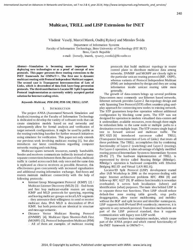
INET 2.4 framework is according to our knowledge as follows. We merged functionality of generic IPv4 Router
and IPv6 Router6 nodes, so that we created the dual-stack
capable router – ANSARouter.
Figure 1. ANSARouter st ructure with highlighted contribution
We have searched in scientific community around simulation and modeling for other PIM implementations prior
to our work. Limited versions (e.g., without PIM State Refresh messages) exist for NS-2 [10] or OPNET [11]. However, none
of them provides robust implementation (i.e., with finite-state
machines implementing whole RFC behavior). Also, existing OMNeT++ multicast attempts proved to be depreciated [12].
We have similarly looked for TRILL, but did not find any
project trying to create TRILL simulation implementation . Limited LISP implementation was created [13] to support
LISP MobileNode NAT traversal [14]. However, it is intended for the INET-20100323 and OMNeT++ 4.0.
Resulting structure of ANSARouter is in Figure 1 with highlighted simulation modules that are described within this
paper.
III. IMPLEMENTATION
A. PIM – Theory of operation
All multicast routing protocols provide a function to answer the question, “How to create routing path between
sender(s) and receivers?” Baselines for this functionality are
distribution trees of the following two types: Source trees – The separate shortest path tree is built for
each source of multicast data. A sender is the root and receivers are the leaves. However, memory and computation
overhead causes this type is not scalable in the case of a network with many sources of multicast. In these situations
usually the Shared tree is used.
Shared trees – A router called Rendezvous Point (RP) exists in a topology that serves as a meeting point for the
traffic from multiple sources to reach destinations. The shared tree interconnects RP with all related receivers.
There are four PIM operational modes: PIM Dense Mode (PIM-DM), PIM Sparse Mode (PIM-SM), Bidirectional PIM
(BiDir-PIM) and PIM Source-Specific Multicast (PIM-SSM). All of them differ in signalization, employed distribution trees
and suitable applications.
Multicast routing support is performed by one dedicated router on each LAN segment elected based on PIM Hello
messages. This router is called designated router (DR) and it is the one with the highest priority or highest IP address.
PIM-DM is recommended for topologies with only one multicast source and lots of receivers. PIM-DM can be easily
deployed without burdening configuration on active devices.
However, PIM-DM does not scale well when number of sources increases. For this situation or for topologies with
sparsely connected receivers, PIM-SM is suggested to be employed. Sparse mode scales much better in large topologies
comparing to Dense mode, but configuration and administration is more complicated. PIM-SSM suits for
multicast groups containing multiple sources providing the
same content where client using IGMPv3 or MLDv2 may specify from which particular source it wants to receive data.
BiDir-PIM is intended for topologies where many-to-many communication occurs. Currently, PIM-DM and PIM-SM are
widely deployed PIM variants. Hence, we decided to implement them as the first.
PIM-DM idea consists of initial data delivery to all multicast-enable destinations (to flood multicast traffic
everywhere), where routers prune themselves explicitly from
the distribution tree if they are not a part of the multicast group. PIM-DM is not taking advantage of RP; thus, it is using
source trees only. PIM-DM routers exchange following messages during
operation:
242
International Journal on Advances in Networks and Services, vol 7 no 3 & 4, year 2014, http://www.iariajournals.org/networks_and_services/
2014, © Copyright by authors, Published under agreement with IARIA - www.iaria.org
PIM Hello – Used for neighbor detection and
forming adjacencies. It contains all settings of shared parameters used for DR election;
PIM Prune/Join – Sent towards upstream router by downstream device to either explicitly prune a source
tree, or to announce willingness to receive multicast data by another downstream device in case of
previously solicited PIM Prune;
PIM Graft – Sent from a downstream to an upstream
router to join previously pruned distribution tree;
PIM Graft-Ack – Sent from an upstream to a downstream router to acknowledge PIM Graft;
PIM State Refresh – Pruned router refreshes prune state upon receiving this message;
PIM Assert – In case of multi-access segment with multiple multicast-enabled routers one of them must
be elected as an authoritative spokesman. Mutual exchange of PIM Asserts accomplishes this election.
On the contrary to PIM-DM, PIM-SM works with different principle where initially no device wants to receive
multicast. Thus, all receivers must explicitly ask for multicast
delivery and then routers forward multicast data towards end-hosts. PIM-SM employs both types of multicast distribution
trees. Sources of multicast are connected with RP by source trees – source of multicast is the root of a source tree. RP is
connected with multicast receivers by shared trees – RP is the root of shared tree. Multicast data is traversing from sources
down by source tree to RP and further down by shared tree to
receivers. PIM-SM cannot work properly until all PIM routers in a network do not know exactly which router is RP for a
given multicast group. PIM-SM exchanges subsequent message types:
PIM Hello – same as PIM-DM.
PIM Register – Sent by source’s DR towards RP
whenever new source of multicast is detected.
PIM Register-Stop – Solicited confirmation of PIM
Register. It is sent by RP in reverse direction that
source’s DR can stop registering process of a new source. RP is aware of multicast data and may send
them to receivers via shared tree.
PIM Prune/Join – This message forms the shape of
source and shared distribution trees. Multiple sources could provide data to the same multicast group –
each one of them sends data via own source tree towards RP, from here data is reflected to receivers
via shared tree.
PIM Assert – same as PIM-DM. The thorough survey on PIM-DM and PIM-SM message
exchange scenarios are out of scope of this paper. More can be found in RFC 3973 [15] and RFC 4601 [16]; let us state
that our implementations (i.e., finite-state machines, message structure, etc.) fully comply with IETF’s standards.
B. PIM – Design
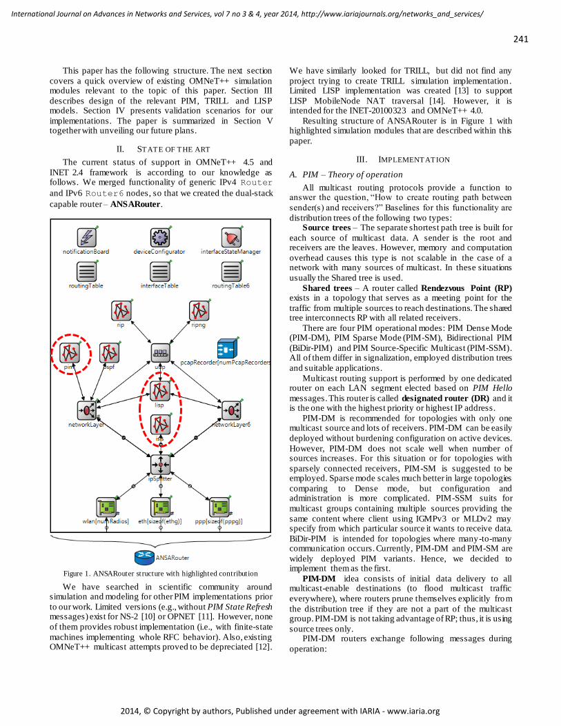
We have synthetized multiple finite-state machines that
describe behavior of PIM-DM and PIM-SM with reference to used timers and exchanged PIM messages [17]. Figure 2
shows implemented architecture of the pim module.
Figure 2. Proposed PIM module design
Besides previous modules, there were also some minor alternations to IPv4 networkLayer as well as to IPv4
routingTable module.
Implementation is done in NED (model design) and C++ (model behavior) languages. Brief description of implemented
components is summarized in Table I.
TABLE I. DESCRIPTION OF PIM SUBMODULES
Name Description
pimSplitter
This submodule is connected with INET
networkLayer. It inspects all PIM messages and passes them to appropriate PIM submodules.
pimDM The main implementation and logic of PIM-DM protocol is over here.
pimSM The main implementation and logic of PIM-SM
protocol is over here.
pim
InterfaceTable
Stores all PIM relevant information for each
router’s interface.
pim
NeighborTable
Keeps state of formed PIM adjacencies and information about neighbors (PIM version they are using, priorities, neighbors IPs).
pimSSM, pimBiDir
Prepared as a placeholder for upcoming implementations of BiDir-PIM and PIM-SSM
variants.
C. TRILL – Theory of operation
TRILL provides loop-less topology for Layer-2. It replaces obsolescent STP protocol. Devices that actually run
TRILL are called RBridges. The work of RBridge can be
divided into two separate components – routing and switching.
The first component is based on link state approach and employs so called IS-IS Layer-2 implementation. All
RBridges run instance of this altered IS-IS to exchange link-state statuses (LSPs) for the whole topology. The IS-IS Layer-
2 instance uses single IS-IS Level-1 area with zero-length
Area-ID, which contains all RBridges as if they are in one large flat Layer-2 network. Designated RBridge (DRB) is
elected from the set of RBridges on shared link and it chooses Appointed Forwarder (AF) for this link. DRB informs others
about chosen AF via TRILL Hello messages. Appointed Forwarder acts as ingress and egress gate to the campus
(area covered by single TRILL instance). Designated VLAN
carries all TRILL-encapsulated traffic between RBridges.
243
International Journal on Advances in Networks and Services, vol 7 no 3 & 4, year 2014, http://www.iariajournals.org/networks_and_services/
2014, © Copyright by authors, Published under agreement with IARIA - www.iaria.org
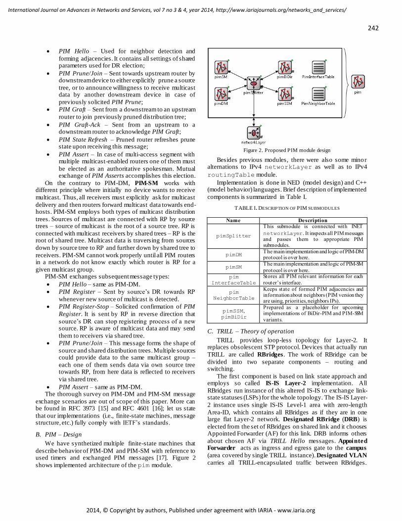
DRB is in charge of appointing Designated VLAN.
Encapsulated frame format is depicted in Figure 3. The second component is TRILL itself. The TRILL
distinguishes five classes of traffic:
TRILL L2 Control – Frames of low level Layer-2
protocols like STP (e.g., BPDUs). TRILL control frames are processed locally.
Native – Non-TRILL traffic from/to hosts. Only AF sends and receives native traffic on shared segment.
TRILL Data – TRILL encapsulated frames with
Ethernet’s header field Ethertype set to 0x22F3.
TRILL Control – Frames that belongs to Layer-2 IS-
IS protocol. They have Ethertype set to 0x22F4 value.
TRILL other – Other frames, which do not match any of the previous types, are dropped without
acknowledgment. RBridge distinguishes between three port types:
Access Port – handles native non-TRILL traffic from hosts and delimits campus edges.
Trunk Port – handles TRILL Data frames. These
ports are located inside campus.
Hybrid Port – handles both previous traffic types.
This port interconnects partitioned campus across non-TRILL area.
New outer Ethernet header
TRILL header
Original unchanged Ethernet header
Ethernet Payload FCS
Figure 3. TRILL frame encapsulation
Native frame is equipped with TRILL header (see Figure 4) as soon as it passes first RBridge. Additionally, outer
Ethernet header is also prepended. Subsequently, either whole encapsulated frame is sent towards egress RBridge that has
destination host connected, or native frame is forwarded on local port. Multi-destination frame is used when destination
is unknown. RBridge sends this kind of frame: a) in native
form on all links where this RBridge acts as an AF; b) as TRILL encapsulated to its neighbors according to given
distribution tree. RBridge learns the source MAC address each time it receives frame in native form on the port for
which this RBridge is AF.
Version (2b) Reserved (2b) M (1b)
Op-Length (5b) Hop Count (6b) Egress RBridge Nickname (16b) Ingress RBridge Nickname (16b)
Options...
Figure 4. TRILL header format When RBridge receives TRILL encapsulated frame, it
either sends it toward egress RBridge according to
RBMACTable (unicast case), or to all connected branches of
a given distribution tree (multi-destination case). If the
receiving RBridge is also the egress RBridge then the frame
is decapsulated and sent to the local port.
Distribution Trees are used when sending multi-
destination frames. RBridge with the highest priority in campus decides about the number of distribution trees and
their roots. Complete description of TRILL protocol is out of scope of
this document.
D. TRILL – Design
We created a new RBridge simulation model. This model comprises existing IS-IS module that has been extended by
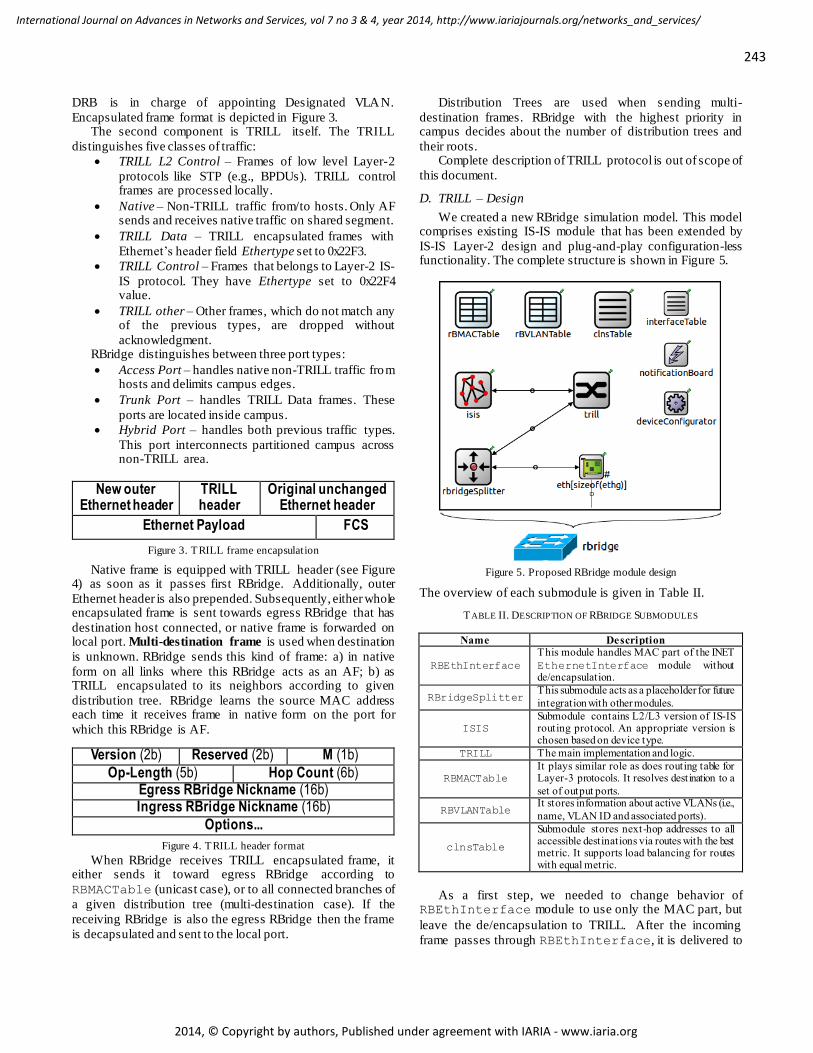
IS-IS Layer-2 design and plug-and-play configuration-less functionality. The complete structure is shown in Figure 5.
Figure 5. Proposed RBridge module design
The overview of each submodule is given in Table II.
T ABLE II. DESCRIPTION OF RBRIDGE SUBMODULES
Name Description
RBEthInterface
This module handles MAC part of the INET
EthernetInterface module without de/encapsulation.
RBridgeSplitter This submodule acts as a placeholder for future
integration with other modules.
ISIS
Submodule contains L2/L3 version of IS-IS routing protocol. An appropriate version is chosen based on device type.
TRILL The main implementation and logic.
RBMACTable
It plays similar role as does routing table for Layer-3 protocols. It resolves destination to a
set of output ports.
RBVLANTable It stores information about active VLANs (i.e.,
name, VLAN ID and associated ports).
clnsTable
Submodule stores next-hop addresses to all accessible destinations via routes with the best metric. It supports load balancing for routes with equal metric.
As a first step, we needed to change behavior of RBEthInterface module to use only the MAC part, but
leave the de/encapsulation to TRILL. After the incoming
frame passes through RBEthInterface, it is delivered to
244
International Journal on Advances in Networks and Services, vol 7 no 3 & 4, year 2014, http://www.iariajournals.org/networks_and_services/
2014, © Copyright by authors, Published under agreement with IARIA - www.iaria.org
TRILL module. Then the frame is classified and processed
based on previously mentioned traffic class. For unicast frames, the sender is learned and put into RBMACTable.
Every RBridge generates Distribution trees independently
based on its link-state database content.
E. LISP – Theory of operation
LISP accomplishes loc/id separation by splitting the IP
address into two namespaces:
Routing Locator (RLOC) namespace with addresses fulfilling their localization purposes by
telling where device is connected in the network.
Endpoint Identifier (EID) namespace where each
device has unique name that distinct it from each other.
There is (and probably always will be) a non-LISP namespace where direct LISP communication is (even
intentionally) not supported. Apart from namespaces exist
also: a) specialized routers performing map-and-encap that interconnects different namespaces; b) dedicated devices
maintaining mapping system; c) proxy routers allowing communication between LISP and non-LISP world.
LISP mapping system performs lookups where a set of RLOCs is retrieved for a given EID. Following map-and-
encap principle, original (inner) header is encapsulated by a new (outer) header, which is appended when crossing borders
from EID to RLOC namespace. Whenever packet is crossing
back from RLOC to EID namespace, packet is decapsulated by stripping off outer header. LISP places additional UDP
header succeeded by LISP header between inner and outer header. LISP uses reserved port numbers – 4341 for data and
4342 for signalization traffic. Currently any combination of IPv4/v6 headers is supported.
Basic components are Ingress Tunnel Router (ITR) and
Egress Tunnel Router (ETR). Both are border devices between EID and RLOC space, the only difference is in which
direction they are operated. The single device could be either ITR only, or ETR only, or ITR and ETR at the same time.
Usually, the functionality is dual and we denote this kind of device with abbreviation xTR.
ITR is the exit point from EID space (a.k.a. LISP site) to
RLOC space, which encapsulates original packet. This process may consist of querying mapping system followed by
updating local map cache where EID-to-RLOC mapping pairs are stored for limited time to reduce signalization
overhead. ETR is the exit from RLOC space to EID space, which
decapsulates original header. This means that outer header plus auxiliary UDP and LISP headers are stripped off. ETR is
also announcing all LISP sites (their EID addresses) and by
which RLOCs they are accessible. LISP mapping system is primary employing two
components – Map Resolver (MR) and Map Server (MS). Looking for RLOC to EID is analogous process as DNS name
resolution. In case of DNS, host asks its DNS resolver (configured within OS) which IP address belongs to a given
fully qualified domain name. DNS server responds with
cached answer or delegates the question recursively or iteratively to another DNS server according to the name
hierarchy. In case of LISP, the querier is ITR that needs to find
out, which RLOCs could be used to reach a given EID. ITR has preconfigured MR, which is bothered each time mapping
is needed. Mapping queries are data-driven. This means that data transfer between LISP sites initiates mapping process and
data itself is postponed until mapping is discovered. Map cache on each ITR holds only those records that are actively
needed by ongoing traffic.
Following list contains all LISP mapping signalization messages with their brief description. LISP control traffic are
LISP packets without inner header – just outer header + UDP header with source and destination ports set on 4342 +
appropriate LISP message header. Structural details of each message can be found in RFC 6830 [18].
LISP Map-Register – Each ETR announces as authority one or more LISP sites to the MS
employing this message. Each registration contains a
list of RLOCs to a given EID with properties.
LISP Map-Request – ITR generates this request
whenever it needs to discover current EID-to-RLOC mapping and sends it into mapping system.
LISP Map-Reply – This is solicited response from the mapping system to a previous request and contains
all RLOCs to a certain EID together with their attributes. Each ITR has its own map cache where
information from replies are stored for a limited time
and used locally to reduce signalization overhead of mapping system.
LISP Negative Map-Reply – Mapping system generates this message as a response whenever given
identifier is not the EID and thus proxy routing for non-native LISP communication must occur.
MR accepts LISP Map-Requests sent by ITR. Message is either delegated further into mapping system (namely to
appropriate MS), or MR responds with LISP Negative Map-
Reply if questioned EID is address from non-LISP world. Every MS maintains mapping database of LISP sites that
are advertised by LISP Map-Register messages. If MS receives LISP Map-Request then: a) either MS responds
directly to querying ITR – it is allowed to do that because MS has all the necessary information in its mapping database; b)
or MS forwards request towards designated ETR that is
successfully registered to MS for target EID. Each RLOC record to a given EID has two attributes –
priority and weight. Priority (one byte long value in range from 0 to 255) expresses each RLOC preference. The locator
with the lowest priority is used by ITR when creating outer header. Communication may be load-balance based on weight
(in range from 0 to 100) between multiple RLOCs sharing the
same priority. Priority value 255 means that locator must not be used for traffic forwarding. Zero weight means that RLOC
may be used for load-balancing according to ITR wishes.
F. LISP – Design
LISP xTR, MR and MS functionality is currently implemented within LISPRouting compound module that
is interconnected with both (IPv4) networkLayer and
(IPv6) networkLayer6. It consists of three submodules
245
International Journal on Advances in Networks and Services, vol 7 no 3 & 4, year 2014, http://www.iariajournals.org/networks_and_services/
2014, © Copyright by authors, Published under agreement with IARIA - www.iaria.org
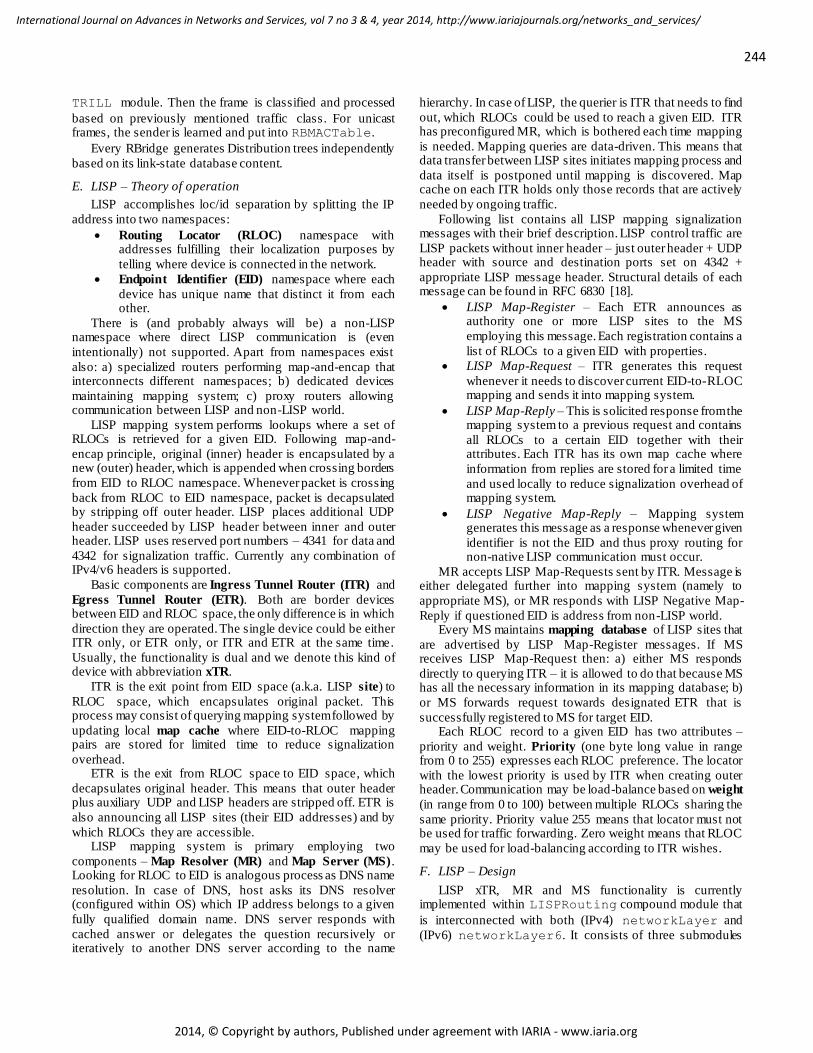
that are depicted in the Figure 6 and described in Table below
the figure.
Figure 6. Proposed LISPRouting module design
T ABLE III. DESCRIPTION OF LISPROUTING SUBMODULES
Name Description
lispCore
The heart that is responsible for handling LISP control and data traffic. It independently combines functionality of ITR, ETR, MR and
MS. In case of ITR, this involves encapsulation and active maintenance of map cache. In case of ETR, it is responsible for decapsulation process and site registration. In case of MR, it
simply delegates map queries. In case of MS, it maintains mapping database.
lispMapCache
Local LISP map cache that is populated on demand by routing data traffic between LISP sites. Each record (EID-to-RLOC mapping)
has its own separate handling (i.e., expiration, refreshment, availability of RLOCs).
lispMapDatabase
MS’s mapping database that maintains LISP site registration by ETRs. It contains site specific information (e.g., shared key, statistics
of registrars and times of registration). Each site also contains known EID-to-RLOC mappings.
Minor changes were done also to both networkLayer/6 submodules in order to divert LISP data
traffic intended for encapsulation/decapsulation towards
LISPRouting module (UDP port 4341). LISPRouting
is also registered with UDPSocket on local port 4342 to
handle LISP control messages coming from UDP submodule.
IV. TESTING
In this section, we provide information on testing and validation of our implementations using several test scenarios.
We have built exactly the same topologies for both simulation and real network and observed (using transparent switchport
analyzers and packet sniffers) relevant messages exchange
between devices. For multicast operation, we compared the results with the
behavior of referential implementation running at Cisco routers (Cisco 2811 routers with IOS operating system version
c2800nm-advipservicesk9-mz.124-25f) and host stations
(with FreeBSD 8.2 OS). For TRILL, we did a comparison only with specifications.
As for LISP, we conducted tests and compared them to a referential behavior of Cisco routers (C7200 routers with IOS
c7200-adventerprisek9-mz.152-4.M2) and host stations (with Windows 7 OS).
A. PIM-DM
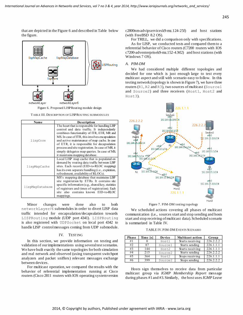
We had considered multiple different topologies and
decided for one which is just enough large to test every multicast aspect and still with scenario easy to follow. In this
testing network (topology is shown in Figure 7), we have three
routers (R1, R2 and R3), two sources of multicast (Source1
and Source2) and three receivers (Host1, Host2 and
Host3).
Figure 7. PIM-DM testing topology
We scheduled actions covering all phases of multicast
communication (i.e., sources start and stop sending and hosts start and stop receiving of multicast data). Scheduled scenario
is summarized in Table IV.
TABLE IV. PIM-DM EVENTS SCENARIO
Phase Time [s] Device Multicast action Group #1 0 Host1 Starts receiving 226.2.2.2
#2 87 Source1 Starts sending 226.1.1.1
#3 144 Host2 Starts receiving 226.1.1.1 #4 215 Source2 Starts sending 226.2.2.2
#5 364 Host2 Stops receiving 226.1.1.1
#6 399 Source2 Stops sending 226.2.2.2
Hosts sign themselves to receive data from particular multicast group via IGMP Membership Report message
during phases #1 and #3. Similarly, the host uses IGMP Leave
226.2.2.2
226.1.1.1
226.1.1.1
226.2.2.2
246
International Journal on Advances in Networks and Services, vol 7 no 3 & 4, year 2014, http://www.iariajournals.org/networks_and_services/
2014, © Copyright by authors, Published under agreement with IARIA - www.iaria.org
Group message to stop receiving data during phases #5 and
#6. #1) There are no multicast data transferred. Only PIM
Hellos are sent between neighbors. #2) First multicast data appears but, because of no
receivers, routers prune themselves from source distribution tree after initial flooding.
#3) Host2 starts to receive data from group 226.1.1.1 at
the beginning of #3. This means that R2 reconnects to
source tree with help of PIM Graft, which is
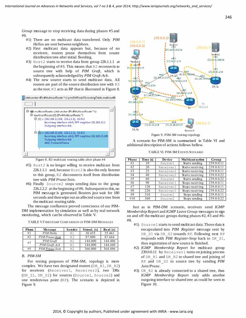
subsequently acknowledged by PIM Graft-Ack . #4) The new source starts to send multicast data. All
routers are part of the source distribution tree with R3
as the root. R3 acts as RP that is illustrated in Figure 8.
Figure 8. R3 multicast routing table after phase #4
#5) Host2 is no longer willing to receive multicast from
226.1.1.1 and, because Host2 is also the only listener
to this group, R2 disconnects itself from distribution
tree with PIM Prune/Join. #6) Finally Source2 stops sending data to the group
226.2.2.2 at the beginning of #6. Subsequent to this, no PIM message is generated. Routers just wait for 180
seconds and then wipe out an affected source tree from the multicast routing table.
The message confluence proved correctness of our PIM-
DM implementation by simulation as well as by real network monitoring, which can be observed in Table V.
TABLE V.T IMESTAMP COMPARISON OF PIM-DM MESSAGES
Phase Message Sender Simul. [s] Real [s] #1 PIM Hello R1 30.435 25.461
#2 PIM Prune/Join R3 87.000 87.664
#3 PIM Graft R2 144.000 144.406
PIM Graft-Ack R1 144.000 144.440
#5 PIM Prune/Join R2 366.000 364.496
B. PIM-SM
For testing purposes of PIM-SM, topology is more
complex. We have two designated routers (DR_R1, DR_R2)
for receivers (Receiver1, Receiver2), two DRs
(DR_S1, DR_S2) for sources (Source1, Source2) and
one rendezvous point (RP). The scenario is depicted in
Figure 9.
Figure 9. PIM-SM testing topology
A scenario for PIM-SM is summarized in Table VI and additional description of actions follows bellow.
TABLE VI. PIM-SM EVENTS SCENARIO
Phase Time [s] Device Multicast action Group #1 10 Source1 Starts sending 239.0.0.11
#2 20 Receiver1 Starts receiving 239.0.0.11
#3 25 Receiver2 Starts receiving 239.0.0.11
#4 40 Receiver2 Starts receiving 239.0.0.22
#5 60 Source2 Starts sending 239.0.0.22
#6 90 Receiver1 Stops receiving 239.0.0.11
#7 120 Receiver2 Stops receiving 239.0.0.11
#8 220 Receiver2 Stops receiving 239.0.0.22
#9 310 Source1 Stops sending 239.0.0.11
#10 360 Source2 Stops sending 239.0.0.22
Just as in PIM-DM scenario, receivers send IGMP
Membership Report and IGMP Leave Group messages to sign on and off the multicast groups during phases #2, #3 and #6-
#8. #1) Source1 starts to send multicast data. Those data is
encapsulated into PIM Register message sent by
DR_S1 via DR_S2 towards RP. Following next RP
responds with PIM Register-Stop back to DR_S1,
thus registration of new source is finished.
#2) IGMP Membership Report for multicast group 239.0.0.11 by Receiver1 turns on joining process
of DR_R1 and DR_R2 to shared tree and joining of
RP and DR_S2 to source tree by sending PIM
Join/Prune.
#3) DR_R2 is already connected to a shared tree, thus
IGMP Membership Report only adds another
outgoing interface to shared tree as could be seen in
Figure 10.
239.0.0.22 239.0.0.11 239.0.0.22
239.0.0.11
239.0.0.11
lo
10.2.2.2
247
International Journal on Advances in Networks and Services, vol 7 no 3 & 4, year 2014, http://www.iariajournals.org/networks_and_services/
2014, © Copyright by authors, Published under agreement with IARIA - www.iaria.org
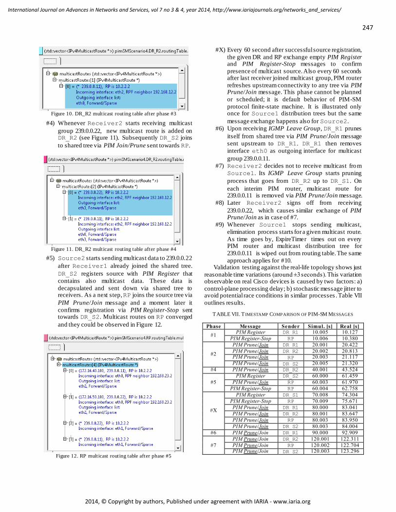
Figure 10. DR_R2 multicast routing table after phase #3
#4) Whenever Receiver2 starts receiving multicast
group 239.0.0.22, new multicast route is added on DR_R2 (see Figure 11). Subsequently DR_S2 joins
to shared tree via PIM Join/Prune sent towards RP.
Figure 11. DR_R2 multicast routing table after phase #4
#5) Source2 starts sending multicast data to 239.0.0.22
after Receiver1 already joined the shared tree.
DR_S2 registers source with PIM Register that
contains also multicast data. These data is
decapsulated and sent down via shared tree to receivers. As a next step, RP joins the source tree via
PIM Prune/Join message and a moment later it
confirms registration via PIM Register-Stop sent towards DR_S2. Multicast routes on RP converged
and they could be observed in Figure 12.
Figure 12. RP multicast routing table after phase #5
#X) Every 60 second after successful source registration,
the given DR and RP exchange empty PIM Register and PIM Register-Stop messages to confirm
presence of multicast source. Also every 60 seconds after last receiver joined multicast group, PIM router
refreshes upstream connectivity to any tree via PIM Prune/Join message. This phase cannot be planned
or scheduled; it is default behavior of PIM-SM
protocol finite-state machine. It is illustrated only once for Source1 distribution trees but the same
message exchange happens also for Source2.
#6) Upon receiving IGMP Leave Group, DR_R1 prunes
itself from shared tree via PIM Prune/Join message
sent upstream to DR_R1. DR_R1 then removes
interface eth0 as outgoing interface for multicast
group 239.0.0.11.
#7) Receiver2 decides not to receive multicast from
Source1. Its IGMP Leave Group starts pruning
process that goes from DR_R2 up to DR_S1. On
each interim PIM router, multicast route for 239.0.0.11 is removed via PIM Prune/Join message.
#8) Later Receiver2 signs off from receiving
239.0.0.22, which causes similar exchange of PIM Prune/Join as in case of #7.
#9) Whenever Source1 stops sending multicast,
elimination process starts for a given multicast route.
As time goes by, ExpireTimer times out on every PIM router and multicast distribution tree for
239.0.0.11 is wiped out from routing table. The same
approach applies for #10. Validation testing against the real-life topology shows just
reasonable time variations (around ±3 seconds). This variation observable on real Cisco devices is caused by two factors: a)
control-plane processing delay; b) stochastic message jitter to avoid potential race conditions in similar processes . Table VII
outlines results.
TABLE VII. T IMESTAMP COMPARISON OF PIM-SM MESSAGES
Phase Message Sender Simul. [s] Real [s]
#1 PIM Register DR_R1 10.005 10.127
PIM Register-Stop RP 10.006 10.380
#2
PIM Prune/Join DR_R1 20.001 20.422
PIM Prune/Join DR_R2 20.002 20.813 PIM Prune/Join RP 20.003 21.117
PIM Prune/Join DR_S2 20.005 21.320
#4 PIM Prune/Join DR_R2 40.001 43.524
#5
PIM Register DR_S2 60.000 61.459
PIM Prune/Join RP 60.003 61.970
PIM Register-Stop RP 60.004 62.758
#X
PIM Register DR_S1 70.008 74.304
PIM Register-Stop RP 70.009 75.671
PIM Prune/Join DR_R1 80.000 83.041
PIM Prune/Join DR_R2 80.001 83.647
PIM Prune/Join RP 80.003 83.950
PIM Prune/Join DR_S2 80.003 84.004
#6 PIM Prune/Join DR_R1 90.000 92.909
#7
PIM Prune/Join DR_R2 120.001 122.311
PIM Prune/Join RP 120.002 122.704 PIM Prune/Join DR_S2 120.003 123.296
248
International Journal on Advances in Networks and Services, vol 7 no 3 & 4, year 2014, http://www.iariajournals.org/networks_and_services/
2014, © Copyright by authors, Published under agreement with IARIA - www.iaria.org
C. TRILL
TRILL testing topology consists of six RBridges and two
stations (Host1 with IP 172.16.30.100 and Host2 with
172.16.3.0.101) as depicted in Figure 14. Both stations belong to VLAN 1. CLNS address plan is in Table IX.
TRILL scenario includes network convergence to stable state and sending ICMP Echo Request/Reply messages (ping)
between two hosts . Each RBridge gradually builds up its routing table (clnsTable) via IS-IS process and generates
distribution trees for each RBridge in topology.
T ABLE VIII. TRILL EVENTS SCENARIO
Phase Time [s] Device Action #1 0 RB* Start sending TRILL Hello
#2 5 RB* Start generating and sending LSPs
#3 10 Host1 Sends ARP Request
#4 10 Host2 Sends ARP Reply
#5 10 Host1 Sends ICMP Echo Request
#6 10 Host2 Sends ICMP Echo Reply
T ABLE IX. DEVICE CONFIGURATION
Device Address RB1 0100.0000.0001
RB2 0100.0000.0002
RB3 0100.0000.0003
RB4 0100.0000.0004
RB5 0100.0000.0005
RB6 0100.0000.0006
The list of important phases (summarized in Table VIII) for TRILL verification scenario follows down below:
#1) All RBridges start sending TRILL hello messages in
simulation time t=0s to discover their neighbors.
All neighborships converge to Report state after 2.8
seconds. #2) At time t=5s RBridges generate and send LSPs to
neighbors. Topology is completely converged at a
time t=5.9s and each RBridge initiate shortest-
path first algorithm to fill up clnsTable. The
content of this table for RB4 is depicted in Figure 13.
Highlighted line shows two equal cost paths to RB1
with metric 20.
Figure 13. RB4’s clnsTable
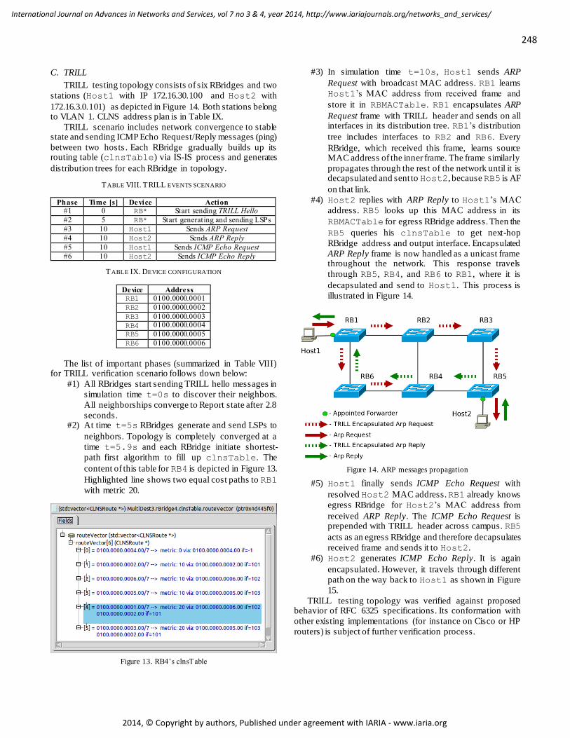
#3) In simulation time t=10s, Host1 sends ARP
Request with broadcast MAC address. RB1 learns
Host1’s MAC address from received frame and
store it in RBMACTable. RB1 encapsulates ARP
Request frame with TRILL header and sends on all interfaces in its distribution tree. RB1’s distribution
tree includes interfaces to RB2 and RB6. Every
RBridge, which received this frame, learns source MAC address of the inner frame. The frame similarly
propagates through the rest of the network until it is decapsulated and sent to Host2, because RB5 is AF
on that link.
#4) Host2 replies with ARP Reply to Host1’s MAC
address. RB5 looks up this MAC address in its
RBMACTable for egress RBridge address. Then the
RB5 queries his clnsTable to get next-hop
RBridge address and output interface. Encapsulated
ARP Reply frame is now handled as a unicast frame throughout the network. This response travels
through RB5, RB4, and RB6 to RB1, where it is
decapsulated and send to Host1. This process is
illustrated in Figure 14.
Figure 14. ARP messages propagation
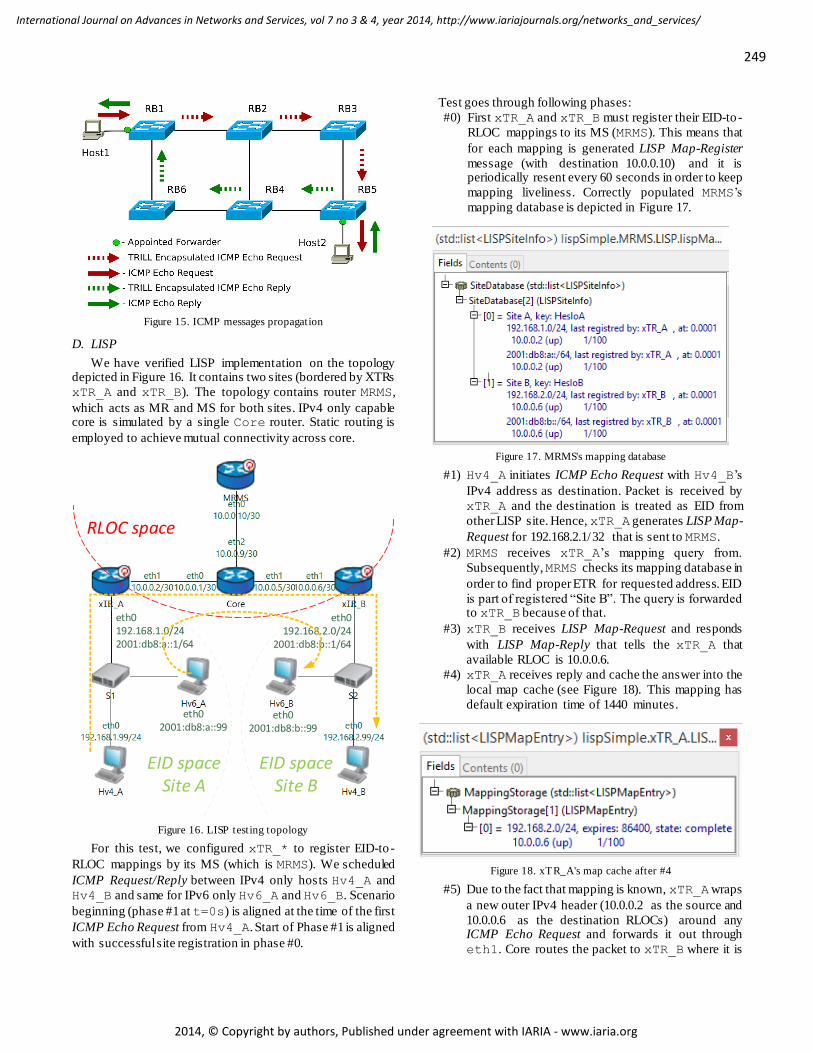
#5) Host1 finally sends ICMP Echo Request with
resolved Host2 MAC address. RB1 already knows
egress RBridge for Host2’s MAC address from
received ARP Reply. The ICMP Echo Request is prepended with TRILL header across campus. RB5
acts as an egress RBridge and therefore decapsulates
received frame and sends it to Host2.
#6) Host2 generates ICMP Echo Reply. It is again
encapsulated. However, it travels through different
path on the way back to Host1 as shown in Figure
15.
TRILL testing topology was verified against proposed behavior of RFC 6325 specifications. Its conformation with
other existing implementations (for instance on Cisco or HP
routers) is subject of further verification process.
249
International Journal on Advances in Networks and Services, vol 7 no 3 & 4, year 2014, http://www.iariajournals.org/networks_and_services/
2014, © Copyright by authors, Published under agreement with IARIA - www.iaria.org
Figure 15. ICMP messages propagation
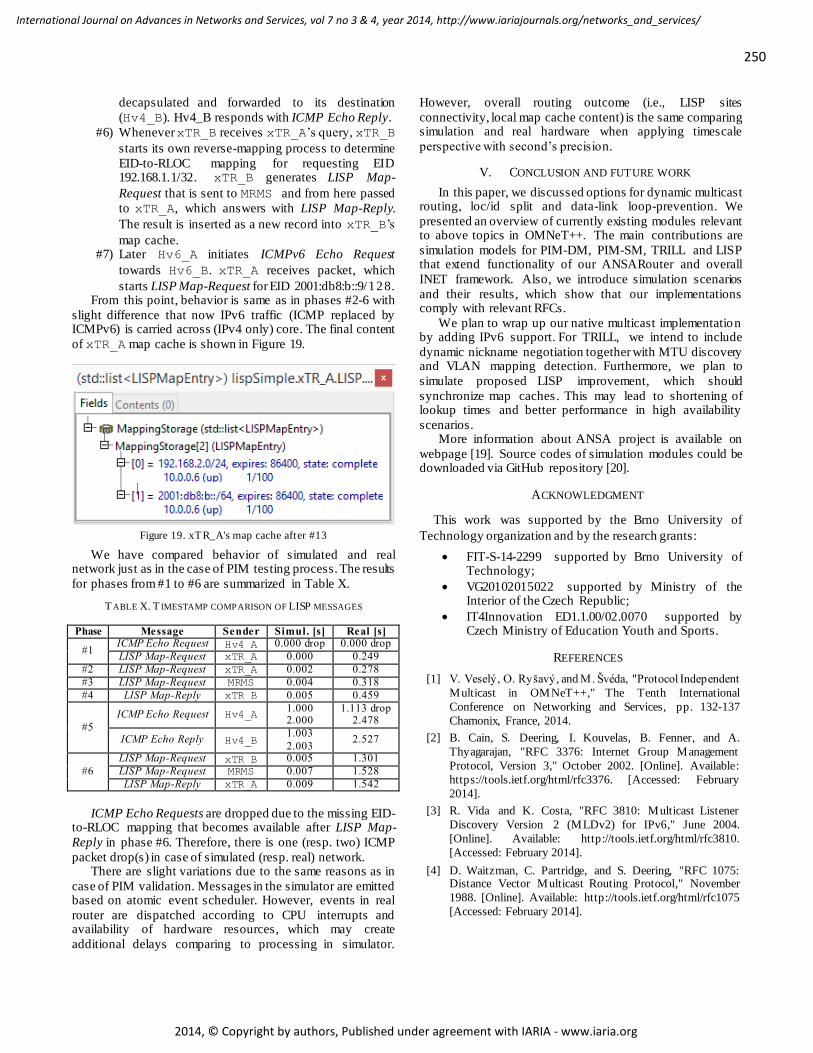
D. LISP
We have verified LISP implementation on the topology depicted in Figure 16. It contains two sites (bordered by XTRs
xTR_A and xTR_B). The topology contains router MRMS,
which acts as MR and MS for both sites. IPv4 only capable core is simulated by a single Core router. Static routing is
employed to achieve mutual connectivity across core.
Figure 16. LISP testing topology
For this test, we configured xTR_* to register EID-to -
RLOC mappings by its MS (which is MRMS). We scheduled
ICMP Request/Reply between IPv4 only hosts Hv4_A and
Hv4_B and same for IPv6 only Hv6_A and Hv6_B. Scenario
beginning (phase #1 at t=0s) is aligned at the time of the first
ICMP Echo Request from Hv4_A. Start of Phase #1 is aligned
with successful site registration in phase #0.
Test goes through following phases:
#0) First xTR_A and xTR_B must register their EID-to -
RLOC mappings to its MS (MRMS). This means that
for each mapping is generated LISP Map-Register
message (with destination 10.0.0.10) and it is periodically resent every 60 seconds in order to keep
mapping liveliness. Correctly populated MRMS’s
mapping database is depicted in Figure 17.
Figure 17. MRMS's mapping database
#1) Hv4_A initiates ICMP Echo Request with Hv4_B’s
IPv4 address as destination. Packet is received by
xTR_A and the destination is treated as EID from
other LISP site. Hence, xTR_A generates LISP Map-
Request for 192.168.2.1/32 that is sent to MRMS.
#2) MRMS receives xTR_A’s mapping query from.
Subsequently, MRMS checks its mapping database in
order to find proper ETR for requested address. EID
is part of registered “Site B”. The query is forwarded to xTR_B because of that.
#3) xTR_B receives LISP Map-Request and responds
with LISP Map-Reply that tells the xTR_A that
available RLOC is 10.0.0.6.
#4) xTR_A receives reply and cache the answer into the
local map cache (see Figure 18). This mapping has
default expiration time of 1440 minutes.
Figure 18. xTR_A's map cache after #4
#5) Due to the fact that mapping is known, xTR_A wraps
a new outer IPv4 header (10.0.0.2 as the source and
10.0.0.6 as the destination RLOCs) around any ICMP Echo Request and forwards it out through
eth1. Core routes the packet to xTR_B where it is
eth0192.168.1.0/242001:db8:a::1/64
eth0192.168.2.0/24
2001:db8:b::1/64
eth02001:db8:a::99
eth02001:db8:b::99
EID spaceSite A
EID spaceSite B
RLOC space
250
International Journal on Advances in Networks and Services, vol 7 no 3 & 4, year 2014, http://www.iariajournals.org/networks_and_services/
2014, © Copyright by authors, Published under agreement with IARIA - www.iaria.org
decapsulated and forwarded to its destination
(Hv4_B). Hv4_B responds with ICMP Echo Reply.
#6) Whenever xTR_B receives xTR_A’s query, xTR_B
starts its own reverse-mapping process to determine
EID-to-RLOC mapping for requesting EID 192.168.1.1/32. xTR_B generates LISP Map-
Request that is sent to MRMS and from here passed
to xTR_A, which answers with LISP Map-Reply.
The result is inserted as a new record into xTR_B’s
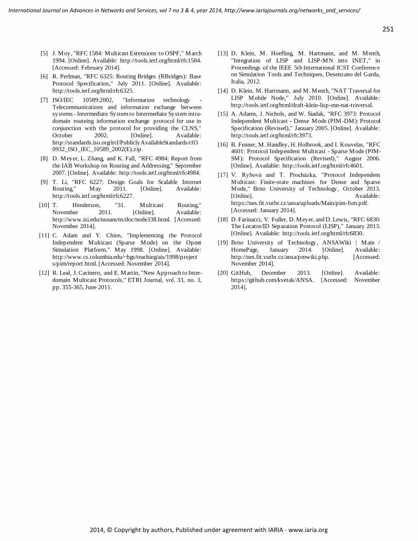
map cache. #7) Later Hv6_A initiates ICMPv6 Echo Request
towards Hv6_B. xTR_A receives packet, which
starts LISP Map-Request for EID 2001:db8:b::9/128. From this point, behavior is same as in phases #2-6 with
slight difference that now IPv6 traffic (ICMP replaced by ICMPv6) is carried across (IPv4 only) core. The final content
of xTR_A map cache is shown in Figure 19.
Figure 19. xTR_A's map cache after #13
We have compared behavior of simulated and real network just as in the case of PIM testing process. The results
for phases from #1 to #6 are summarized in Table X.
T ABLE X. T IMESTAMP COMPARISON OF LISP MESSAGES
Phase Message Sender Simul. [s] Real [s]
#1 ICMP Echo Request Hv4_A 0.000 drop 0.000 drop
LISP Map-Request xTR_A 0.000 0.249
#2 LISP Map-Request xTR_A 0.002 0.278
#3 LISP Map-Request MRMS 0.004 0.318
#4 LISP Map-Reply xTR_B 0.005 0.459
#5
ICMP Echo Request Hv4_A 1.000 2.000
1.113 drop 2.478
ICMP Echo Reply Hv4_B 1.003
2.003 2.527
#6
LISP Map-Request xTR_B 0.005 1.301
LISP Map-Request MRMS 0.007 1.528
LISP Map-Reply xTR_A 0.009 1.542
ICMP Echo Requests are dropped due to the missing EID-to-RLOC mapping that becomes available after LISP Map-
Reply in phase #6. Therefore, there is one (resp. two) ICMP
packet drop(s) in case of simulated (resp. real) network. There are slight variations due to the same reasons as in
case of PIM validation. Messages in the simulator are emitted based on atomic event scheduler. However, events in real
router are dispatched according to CPU interrupts and availability of hardware resources, which may create
additional delays comparing to processing in simulator.
However, overall routing outcome (i.e., LISP sites
connectivity, local map cache content) is the same comparing simulation and real hardware when applying timescale
perspective with second’s precision.
V. CONCLUSION AND FUTURE WORK
In this paper, we discussed options for dynamic multicast routing, loc/id split and data-link loop-prevention. We
presented an overview of currently existing modules relevant to above topics in OMNeT++. The main contributions are
simulation models for PIM-DM, PIM-SM, TRILL and LISP that extend functionality of our ANSARouter and overall
INET framework. Also, we introduce simulation scenarios
and their results, which show that our implementations comply with relevant RFCs.
We plan to wrap up our native multicast implementation by adding IPv6 support. For TRILL, we intend to include
dynamic nickname negotiation together with MTU discovery and VLAN mapping detection. Furthermore, we plan to
simulate proposed LISP improvement, which should
synchronize map caches. This may lead to shortening of lookup times and better performance in high availability
scenarios. More information about ANSA project is available on
webpage [19]. Source codes of simulation modules could be downloaded via GitHub repository [20].
ACKNOWLEDGMENT
This work was supported by the Brno University of
Technology organization and by the research grants:
FIT-S-14-2299 supported by Brno University of Technology;
VG20102015022 supported by Ministry of the Interior of the Czech Republic;
IT4Innovation ED1.1.00/02.0070 supported by Czech Ministry of Education Youth and Sports.
REFERENCES
[1] V. Veselý, O. Ryšavý , and M. Švéda, "Protocol Independent
Multicast in OMNeT++," The Tenth International
Conference on Networking and Services, pp. 132-137
Chamonix, France, 2014.
[2] B. Cain, S. Deering, I. Kouvelas, B. Fenner, and A.
Thyagarajan, "RFC 3376: Internet Group Management
Protocol, Version 3," October 2002. [Online]. Available:
https://tools.ietf.org/html/rfc3376. [Accessed: February
2014].
[3] R. Vida and K. Costa, "RFC 3810: Multicast Listener
Discovery Version 2 (MLDv2) for IPv6," June 2004.
[Online]. Available: http://tools.ietf.org/html/rfc3810.
[Accessed: February 2014].
[4] D. Waitzman, C. Partridge, and S. Deering, "RFC 1075: Distance Vector Multicast Routing Protocol," November
1988. [Online]. Available: http://tools.ietf.org/html/rfc1075
[Accessed: February 2014].
251
International Journal on Advances in Networks and Services, vol 7 no 3 & 4, year 2014, http://www.iariajournals.org/networks_and_services/
2014, © Copyright by authors, Published under agreement with IARIA - www.iaria.org
[5] J. Moy, "RFC 1584: Multicast Extensions to OSPF," March
1994. [Online]. Available: http://tools.ietf.org/html/rfc1584.
[Accessed: February 2014].
[6] R. Perlman, "RFC 6325: Routing Bridges (RBridges): Base
Protocol Specification," July 2011. [Online]. Available:
http://tools.ietf.org/html/rfc6325.
[7] ISO/IEC 10589:2002, "Information technology -
Telecommunications and information exchange between systems - Intermediate System to Intermediate System intra-
domain routeing information exchange protocol for use in
conjunction with the protocol for providing the CLNS,"
October 2002. [Online]. Available:
http://standards.iso.org/ittf/PubliclyAvailableStandards/c030932_ISO_IEC_10589_2002(E).zip.
[8] D. Meyer, L. Zhang, and K. Fall, "RFC 4984: Report from
the IAB Workshop on Routing and Addressing," September
2007. [Online]. Available: http://tools.ietf.org/html/rfc4984.
[9] T. Li, "RFC 6227: Design Goals for Scalable Internet Routing," May 2011. [Online]. Available:
http://tools.ietf.org/html/rfc6227.
[10] T. Henderson, "31. Multicast Routing,"
November 2011. [Online]. Available:
http://www.isi.edu/nsnam/ns/doc/node338.html. [Accessed: November 2014].
[11] C. Adam and Y. Chien, "Implementing the Protocol
Independent Multicast (Sparse Mode) on the Opnet
Simulation Platform," May 1998. [Online]. Available:
http://www.cs.columbia.edu/~hgs/teaching/ais/1998/projects/pim/report.html. [Accessed: November 2014].
[12] R. Leal, J. Cacinero, and E. Martin, "New Approach to Inter-
domain Multicast Protocols," ETRI Journal, vol. 33, no. 3,
pp. 355-365, June 2011.
[13] D. Klein, M. Hoefling, M. Hartmann, and M. Menth,
"Integration of LISP and LISP-MN into INET," in
Proceedings of the IEEE 5th International ICST Conference on Simulation Tools and Techniques, Desenzano del Garda,
Italia, 2012.
[14] D. Klein, M. Hartmann, and M. Menth, "NAT Traversal for
LISP Mobile Node," July 2010. [Online]. Available:
http://tools.ietf.org/html/draft-klein-lisp-mn-nat-traversal.
[15] A. Adams, J. Nichols, and W. Siadak, "RFC 3973: Protocol
Independent Multicast - Dense Mode (PIM-DM): Protocol
Specification (Revised)," January 2005. [Online]. Available:
http://tools.ietf.org/html/rfc3973.
[16] B. Fenner, M. Handley, H. Holbrook, and I. Kouvelas, "RFC 4601: Protocol Independent Multicast - Sparse Mode (PIM-
SM): Protocol Specification (Revised)," August 2006.
[Online]. Available: http://tools.ietf.org/html/rfc4601.
[17] V. Rybová and T. Procházka, "Protocol Independent
Multicast: Finite-state machines for Dense and Sparse Mode," Brno University of Technology, October 2013.
[Online]. Available:
https://nes.fit.vutbr.cz/ansa/uploads/Main/pim-fsm.pdf.
[Accessed: January 2014].
[18] D. Farinacci, V. Fuller, D. Meyer, and D. Lewis, "RFC 6830: The Locator/ID Separation Protocol (LISP)," January 2013.
[Online]. Available: http://tools.ietf.org/html/rfc6830.
[19] Brno University of Technology, ANSAWiki | Main /
HomePage, January 2014. [Online]. Available:
http://nes.fit.vutbr.cz/ansa/pmwiki.php. [Accessed: November 2014].
[20] GitHub, December 2013. [Online]. Available:
https://github.com/kvetak/ANSA. [Accessed: November
2014].