Embed Size (px)
Citation preview
MULTIFUNCTIONAIRCRAFTFLIGHTSURFACEELECTRONICCONTROLUNITTESTSYSTEM:A
BETTERAVIONICSVERIFICATIONTOOLModern avionics exemplify safety and mission-critical, dependable systems. These systems continue to become more complex, and they often operate in uncertain environments. Both hardware and software for such systems are tested using a variety of verification tools that must address the final product reliability, fault tolerance, and deterministic timing guarantees. The quality of the tool and the assurance provided by the tool are critical components of the final target system certification. In partnership with UTC Aerospace Systems (UTAS) and other leaders in the test solution industry, Wineman Technology has helped produce an innovative new schema for verification tools that allows more capability at a more competitive cost than more traditional designs. WTI supported our customer (UTAS) in producing a highly adaptable, modular, configurable multi-use electronic control unit test rig (ECUTR) for validating electronic control units for aircraft.
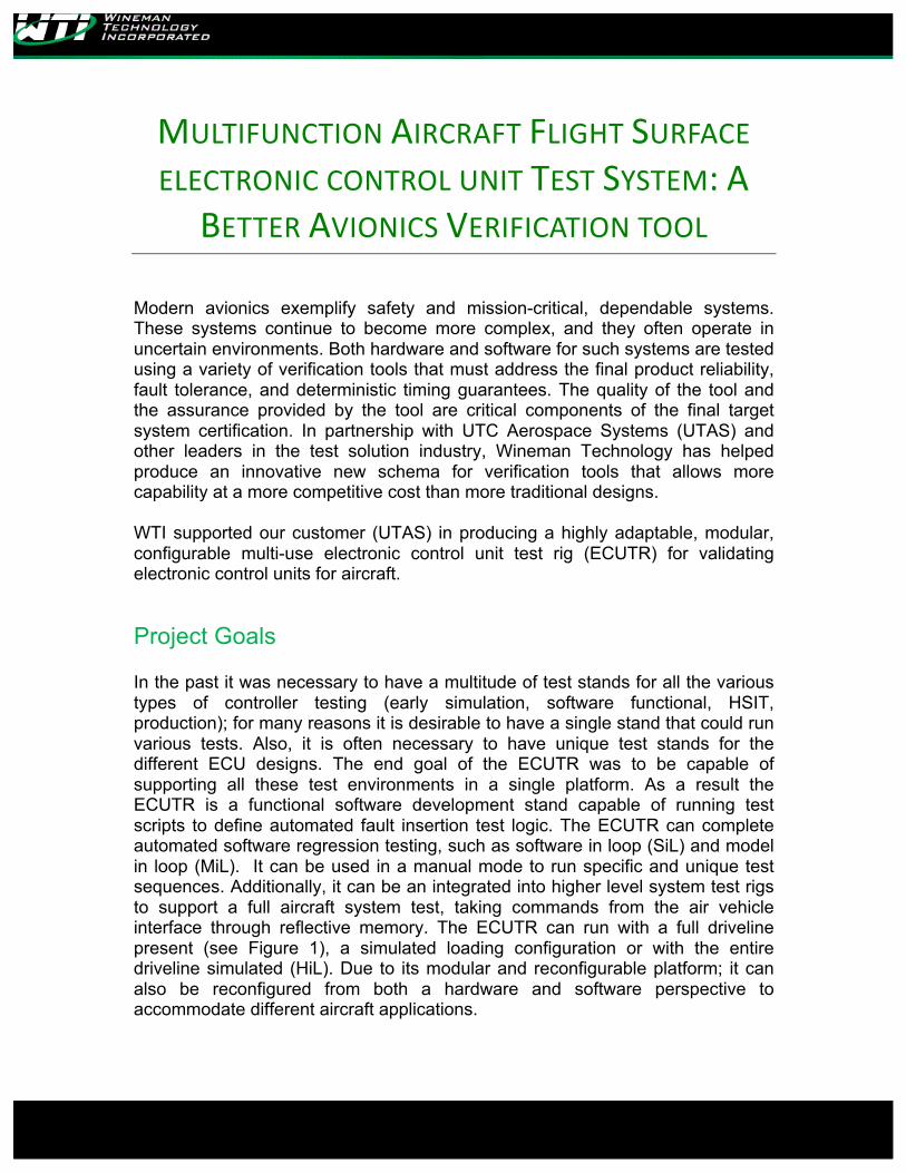
Project Goals In the past it was necessary to have a multitude of test stands for all the various types of controller testing (early simulation, software functional, HSIT, production); for many reasons it is desirable to have a single stand that could run various tests. Also, it is often necessary to have unique test stands for the different ECU designs. The end goal of the ECUTR was to be capable of supporting all these test environments in a single platform. As a result the ECUTR is a functional software development stand capable of running test scripts to define automated fault insertion test logic. The ECUTR can complete automated software regression testing, such as software in loop (SiL) and model in loop (MiL). It can be used in a manual mode to run specific and unique test sequences. Additionally, it can be an integrated into higher level system test rigs to support a full aircraft system test, taking commands from the air vehicle interface through reflective memory. The ECUTR can run with a full driveline present (see Figure 1), a simulated loading configuration or with the entire driveline simulated (HiL). Due to its modular and reconfigurable platform; it can also be reconfigured from both a hardware and software perspective to accommodate different aircraft applications.
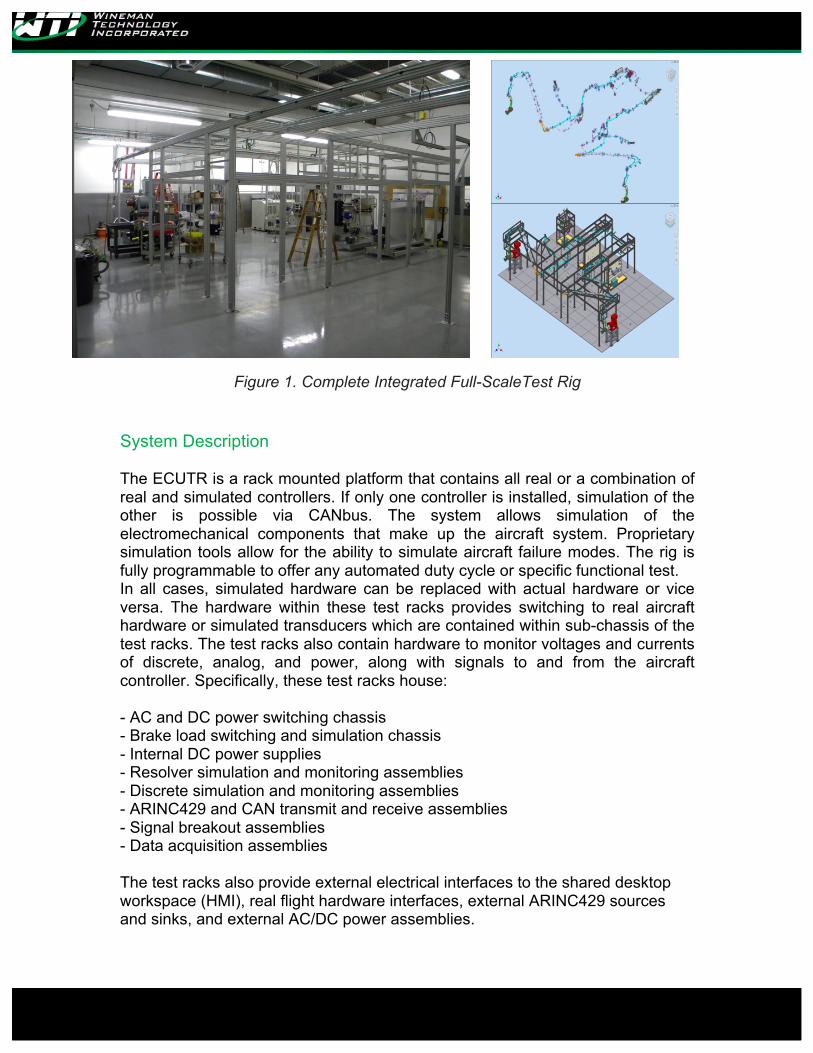
Figure 1. Complete Integrated Full-ScaleTest Rig
System Description The ECUTR is a rack mounted platform that contains all real or a combination of real and simulated controllers. If only one controller is installed, simulation of the other is possible via CANbus. The system allows simulation of the electromechanical components that make up the aircraft system. Proprietary simulation tools allow for the ability to simulate aircraft failure modes. The rig is fully programmable to offer any automated duty cycle or specific functional test. In all cases, simulated hardware can be replaced with actual hardware or vice versa. The hardware within these test racks provides switching to real aircraft hardware or simulated transducers which are contained within sub-chassis of the test racks. The test racks also contain hardware to monitor voltages and currents of discrete, analog, and power, along with signals to and from the aircraft controller. Specifically, these test racks house: - AC and DC power switching chassis - Brake load switching and simulation chassis - Internal DC power supplies - Resolver simulation and monitoring assemblies - Discrete simulation and monitoring assemblies - ARINC429 and CAN transmit and receive assemblies - Signal breakout assemblies - Data acquisition assemblies The test racks also provide external electrical interfaces to the shared desktop workspace (HMI), real flight hardware interfaces, external ARINC429 sources and sinks, and external AC/DC power assemblies.
The ECUTR runs the main software, which is accessible via a remote shared desktop workspace, software which operates both the rig and flight hardware. The main graphical software allows manual test configuration and operation of the test stand. Users can also control and monitor test stand functions over a deterministic reflective memory data bus. The ECUTR HMI consists of all aircraft interfaces, emergency stop switch, keyboard, video, and mouse. The computer that drives these displays is housed within the test racks under uninterruptible power supply (UPS) protection. This HMI is the graphical interface to the software running on the test racks.
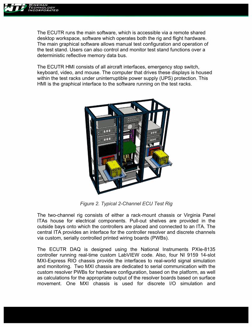
Figure 2. Typical 2-Channel ECU Test Rig The two-channel rig consists of either a rack-mount chassis or Virginia Panel ITAs house for electrical components. Pull-out shelves are provided in the outside bays onto which the controllers are placed and connected to an ITA. The central ITA provides an interface for the controller resolver and discrete channels via custom, serially controlled printed wiring boards (PWBs). The ECUTR DAQ is designed using the National Instruments PXIe-8135 controller running real-time custom LabVIEW code. Also, four NI 9159 14-slot MXI-Express RIO chassis provide the interfaces to real-world signal simulation and monitoring. Two MXI chassis are dedicated to serial communication with the custom resolver PWBs for hardware configuration, based on the platform, as well as calculations for the appropriate output of the resolver boards based on surface movement. One MXI chassis is used for discrete I/O simulation and
measurement in conjunction with another custom PWB and the last chassis is for system control and measurement. The communications (Comms) chassis assembly provides an encapsulated communication interface, including bus power, for the controller. The comms chassis supports the following protocols:
• RS232 x4 • CAN x4 • Ethernet (1) x4 • Ethernet (2) x1 • ARINC 429 (4 Ballard Omnibox Cores)
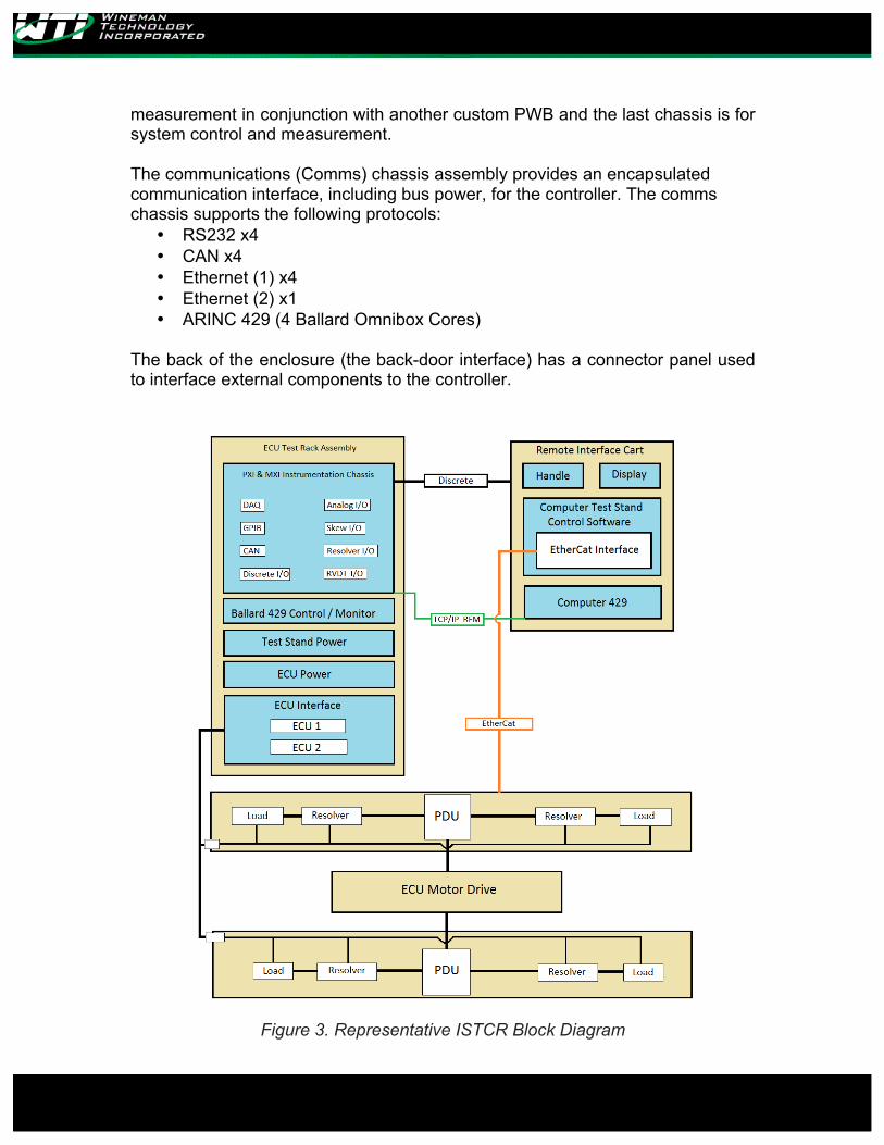
The back of the enclosure (the back-door interface) has a connector panel used to interface external components to the controller.
Figure 3. Representative ISTCR Block Diagram
The Software
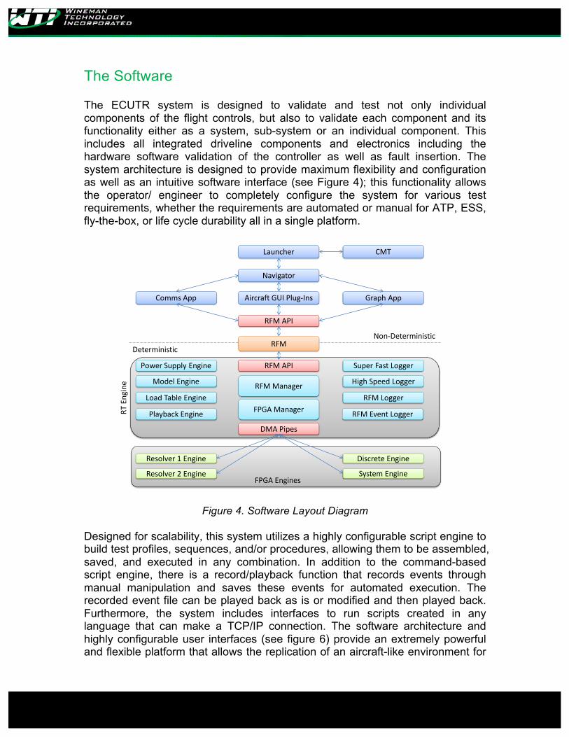
The ECUTR system is designed to validate and test not only individual components of the flight controls, but also to validate each component and its functionality either as a system, sub-system or an individual component. This includes all integrated driveline components and electronics including the hardware software validation of the controller as well as fault insertion. The system architecture is designed to provide maximum flexibility and configuration as well as an intuitive software interface (see Figure 4); this functionality allows the operator/ engineer to completely configure the system for various test requirements, whether the requirements are automated or manual for ATP, ESS, fly-the-box, or life cycle durability all in a single platform.
AircraftGUIPlug-Ins
CMTLauncher
Comms App
Resolver1Engine
RFMAPI
Deterministic
Non-Deterministic
Navigator
RFM
GraphApp
RFMAPI SuperFastLogger
RTEngine RFMManager
FPGAManagerRFMLogger
RFMEventLoggerPlaybackEngine
LoadTableEngine
DMAPipes
ModelEngine
PowerSupplyEngine
HighSpeedLogger
Resolver2Engine
DiscreteEngine
SystemEngineFPGAEngines
Figure 4. Software Layout Diagram
Designed for scalability, this system utilizes a highly configurable script engine to build test profiles, sequences, and/or procedures, allowing them to be assembled, saved, and executed in any combination. In addition to the command-based script engine, there is a record/playback function that records events through manual manipulation and saves these events for automated execution. The recorded event file can be played back as is or modified and then played back. Furthermore, the system includes interfaces to run scripts created in any language that can make a TCP/IP connection. The software architecture and highly configurable user interfaces (see figure 6) provide an extremely powerful and flexible platform that allows the replication of an aircraft-like environment for
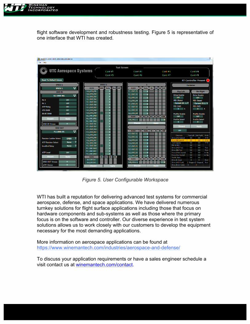
flight software development and robustness testing. Figure 5 is representative of one interface that WTI has created.
Figure 5. User Configurable Workspace
WTI has built a reputation for delivering advanced test systems for commercial aerospace, defense, and space applications. We have delivered numerous turnkey solutions for flight surface applications including those that focus on hardware components and sub-systems as well as those where the primary focus is on the software and controller. Our diverse experience in test system solutions allows us to work closely with our customers to develop the equipment necessary for the most demanding applications. More information on aerospace applications can be found at https://www.winemantech.com/industries/aerospace-and-defense/ To discuss your application requirements or have a sales engineer schedule a visit contact us at winemantech.com/contact.


![7305401 CANBus Ion Del Instructor[1]](https://img.pdfslide.net/doc/110x75/55cf9bf1550346d033a7f411/7305401-canbus-ion-del-instructor1.jpg)