Embed Size (px)
Citation preview
Multimodal Stereo Image Registration for Pedestrian Detection
Stephen Krotosky and Mohan Trivedi
Abstract� This paper presents an approach for the registra-tion of multimodal imagery for pedestrian detection when thesigni�cant depth differences of objects in the scene precludesa global alignment assumption. Using maximization-of-mutual-information matching techniques and sliding correspondencewindows over calibrated image pairs, we demonstrate successfulregistration of color and thermal data. We develop a robustmethod using disparity voting for determining the registrationof each object in the scene and provide a statistically basedmeasure for evaluating the match con�dence. Testing showssuccessful registration in complex scenes with multiple peopleat different depths and levels of occlusion.
I. INTRODUCTION
A large number of automotive accidents involve pedestri-ans. In order to alleviate this problem, ongoing research isbeing performed to detect and track pedestrians from bothmoving vehicles and the static infrastructure. The use ofcamera systems for detection is common, including bothcolor [1] [2] and thermal imagery [3] [4] [5]. While [6] showsa comparison of color and thermal methods, we wish to beable to provide a method for combining the two modalities.
Visual and thermal infrared imagery provide disparate, butcomplementary information about a scene. Visual camerascapture the re�ective light properties of objects in the scene,while thermal infrared cameras are sensitive to the thermalemissivity properties of the same objects. The pairing ofthese two modalities is interesting, as their combination pro-vides information about the scene that is not readily obtainedfrom the human visual system. Namely, the combination ofvisual and thermal infrared imagery can provide the color,depth, motion, and thermal properties that can be used todetect, track and analyze people in a scene.
In order to be able use the data from multiple camerasin a meaningful way, corresponding data from each imagemust be matched, or registered, so that the information fromeach modality can be properly attributed for the higher leveltasks of detection, tracking and analysis. Because the datafrom visual and thermal imagery appears very different ineach image, �nding the appropriate registration for objectsin the corresponding images is a challenging task. Typically,successful multimodal image registration techniques requirethat the cameras and scene be oriented in such a way thatregistration can be described with a global image transfor-mation [7] [8] [9] [10] [11]. Such techniques fail, however,
This work was sponsored in part by grants from the U.S. DoD Tech-nical Support Working Group, U.C. Discovery and Volkswagen ResearchLaboratory.
S. Krotosky and M. Trivedi are with the Computer Vision andRobotics Research Laboratory, University of California, San Diego, 9500Gilman Dr. 0434, La Jolla, CA 92093, USA [email protected],[email protected]
when objects in the scene are located at different observationdepths, as the registration will vary with each object due tothe parallax effects.
This work presents a method for multimodal image reg-istration that can successfully �nd local correspondences forpeople in the scene, even in situations where pedestriansare located at largely different relative depths in the scene,where a global transformation model would surely fail. Usingcalibrated and recti�ed image pairs, we can analyze slidingcorrespondence windows in the color reference image, and�nd its appropriate match in the thermal image using maxi-mization of mutual information. Combining votes from mul-tiple correspondence windows into a disparity accumulationmatrix, we are able to robustly determine the appropriatedisparity for registering each person in the scene and asso-ciate this disparity with a statistically relevant con�dencemeasure. This gives a resultant disparity image that canaccurately register the people in the scene, as well as provideadditional valuable information that can be used for furtherscene segmentation in cases of occlusion. By registeringimages in this way, not only are we able to have successwhen a global transformation is an invalid assumption, butthe resulting disparity image is also a valuable feature thatcan be used for pedestrian detection, tracking and activityanalysis.
II. MULTIMODAL IMAGE REGISTRATION USING MUTUALINFORMATION AND DISPARITY VOTING
Our proposed registration algorithm builds upon the workof Chen, et al. [12] and addresses several of the limitationsof their work. First, by calibrating the color and thermalcameras we can obtain recti�ed images that will reducethe search space for corresponding objects. Although thismethod will also rely on an initial foreground silhouetteextraction, it does not require highly accurate segmentation,and unlike [12] and [13], it also does not require that individ-ual people be segmented from each other, only that they bereasonably segmented from the background. We will alsoutilize the maximization of mutual information techniquefor correspondence matching for multimodal imagery, butwill extend it by using a disparity voting algorithm fromthe results of sliding correspondence windows. This willprovide for robust disparity estimation as well as a statisticalcon�dence value for the disparity measure. Figure 1 showsa �owchart outlining our algorithmic framework.
A. Multimodal image calibrationIt is desirable to calibrate the color and thermal infrared
cameras. Knowing the intrinsic and extrinsic calibration

Fig. 1. Flowchart of multimodal image registration algorithm.
parameters transforms the epipolar lines in the disparity cor-respondence search to lie along the image scanlines, enablingmatching to be a one-dimensional search. Calibration can beperformed using standard techniques, such as those availablein the Camera Calibration Toolbox for Matlab [14]. Thetoolbox assumes input images from each modality where acalibration board is visible in the scene. In typical visualsetups, this is simply a matter of placing a checkerboardpattern in front of the camera. However, due to the largedifferences in visual and thermal imagery, some extra careneeds to be taken to ensure the calibration board looks similarin each modality. A solution is to use a standard calibrationboard and illuminate the scene with high intensity halogenbulbs place behind the cameras. This effectively warms thecheckerboard pattern, making the visually dark checks appearbrighter in the thermal imagery. Placing the board underconstant illumination reduces the blurring associated withthermal diffusion and keeps the checkerboard edges sharp.
B. Image acquisition and foreground extractionThe acquired and recti�ed image pairs are denoted as
IL, the left color image, and IR, the right thermal image.Due to the high differences in imaging characteristics, itis very dif�cult �nd correspondences for the entire scene.Instead, registration is focused on the pixels that correspondto foreground objects of interest (people). Naturally then, itis desirable to determine which pixels in the frame belongto the foreground. In this step, only a rough estimate of theforeground pixels is necessary and a fair amount of falsepositives and negatives is acceptable. Any good segmentation
algorithm could potentially be used with success. For thesespeci�c experiments, foreground segmentation in the visualimagery was done using the codebook model proposed byKim, et al. [15]. In the thermal imagery, the foregroundis obtained using a simple intensity threshold under theassumption that the people in the foreground are hotter thanthe background. The corresponding foreground images areFL and FR, respectively. Additionally, the color image isconverted to grayscale for mutual information based match-ing. Example input images and foreground maps are shownin Fig. 2.
(a) (b)
(c) (d)
Fig. 2. Image acquisition and Foreground extraction: (a) input color image,(b) color foreground map, (c) input thermal image, (d) thermal foregroundmap.
C. Correspondence matching using maximization of mutualinformation
Once the foreground regions are obtained, the correspon-dence matching can begin. Matching occurs by �xing acorrespondence window along one reference image in thepair and sliding the window along the second image that isthe best match. Let h and w be the height and width of theimage, respectively. For each column i ∈ 0 . . . w, let WL,i bea correspondence window in the left image of height h andwidth M centered on column i. De�ne a correspondencewindow WR,i,d in the right image having height h andcentered at a column i + d, where d is a disparity offset.For each column i, a correspondence value is found for alld ∈ dmin . . . dmax.
Given the two correspondence windows WL,i and WR,i,d,we �rst linearly quantize the image to N levels such that
N ≈√
8Mh (1)
where Mh is the area of the correspondence window. The re-sult in (1) comes from Thevenaz and Unser's [16] suggestionthat this equation is reasonable to determine the number oflevels needed to give good results for maximizing the mutual
information between image regions and was also adopted byChen, et al. [12].
Now we can compute the quality of the match betweenthe two correspondence windows by measuring the mutualinformation between them. To do this, we also utilize thestandard mutual information computation techniques for im-age patches also adopted by [12]. The method is outlinedagain here for convenience. The mutual information betweentwo image patches is de�ned as
I(L,R) =∑
l,r
PL,R(l, r) logPL,R(l, r)
PL(l)PR(r)(2)
where PL,R(l, r) is the joint probability mass function (pmf)and PL(l) and PR(r) are the marginal pmf's of the left andright image patches, respectively.
The two-dimensional histogram, g, of the correspondencewindow is utilized to evaluate the pmf's needed to determinethe mutual information. The histogram g is an N by Nmatrix so that for each point, the quantized intensity levelsl and r from the left and right correspondence windowsincrement g(l, r) by one. Normalizing by the total sum ofthe histogram gives the probability mass function
PL,R(l, r) =g(l, r)∑l,r g(l, r)
(3)
The marginal probabilities can be easily determined bysumming PL,R(l, r) over the appropriate dimension.
PL(l) =∑
l
PL,R(l, r) (4)
PR(r) =∑
r
PL,R(l, r) (5)
Now that we are able to determine the mutual informationfor two generic image patches, let's de�ne the mutual in-formation between two speci�c image patches as Ii,d whereagain i is the center of the reference correspondence windowand i+d is the center of the second correspondence window.For each column i, we have a mutual information value Ii,d
for d ∈ dmin . . . dmax. The disparity d∗i that best matchesthe two windows is the one that maximizes the mutualinformation
d∗i = arg maxd
Ii,d (6)
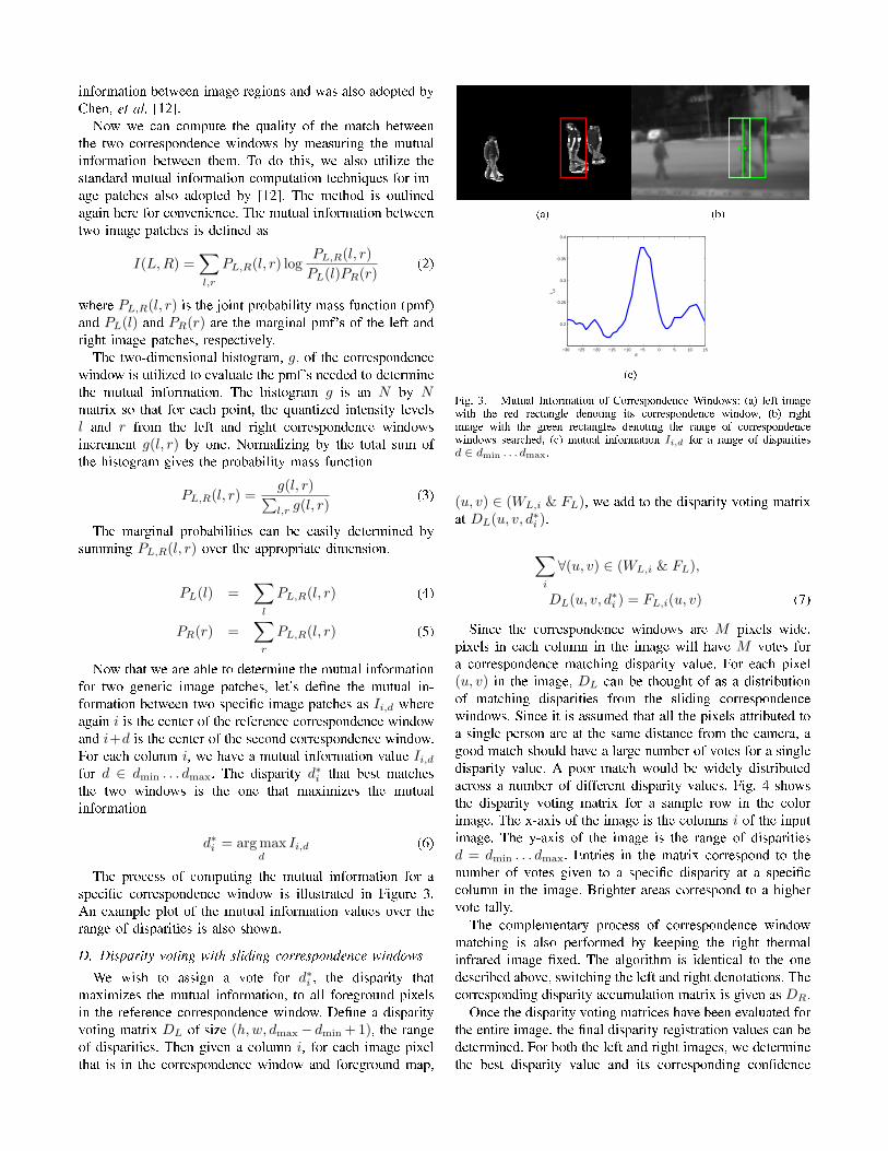
The process of computing the mutual information for aspeci�c correspondence window is illustrated in Figure 3.An example plot of the mutual information values over therange of disparities is also shown.
D. Disparity voting with sliding correspondence windowsWe wish to assign a vote for d∗i , the disparity that
maximizes the mutual information, to all foreground pixelsin the reference correspondence window. De�ne a disparityvoting matrix DL of size (h,w, dmax− dmin + 1), the rangeof disparities. Then given a column i, for each image pixelthat is in the correspondence window and foreground map,
(a) (b)
−30 −25 −20 −15 −10 −5 0 5 10 15
0.2
0.25
0.3
0.35
0.4
d
I i,d
(c)
Fig. 3. Mutual Information of Correspondence Windows: (a) left imagewith the red rectangle denoting its correspondence window, (b) rightimage with the green rectangles denoting the range of correspondencewindows searched, (c) mutual information Ii,d for a range of disparitiesd ∈ dmin . . . dmax.
(u, v) ∈ (WL,i & FL), we add to the disparity voting matrixat DL(u, v, d∗i ).
∑
i
∀(u, v) ∈ (WL,i & FL),
DL(u, v, d∗i ) = FL,i(u, v) (7)
Since the correspondence windows are M pixels wide,pixels in each column in the image will have M votes fora correspondence matching disparity value. For each pixel(u, v) in the image, DL can be thought of as a distributionof matching disparities from the sliding correspondencewindows. Since it is assumed that all the pixels attributed toa single person are at the same distance from the camera, agood match should have a large number of votes for a singledisparity value. A poor match would be widely distributedacross a number of different disparity values. Fig. 4 showsthe disparity voting matrix for a sample row in the colorimage. The x-axis of the image is the columns i of the inputimage. The y-axis of the image is the range of disparitiesd = dmin . . . dmax. Entries in the matrix correspond to thenumber of votes given to a speci�c disparity at a speci�ccolumn in the image. Brighter areas correspond to a highervote tally.
The complementary process of correspondence windowmatching is also performed by keeping the right thermalinfrared image �xed. The algorithm is identical to the onedescribed above, switching the left and right denotations. Thecorresponding disparity accumulation matrix is given as DR.
Once the disparity voting matrices have been evaluated forthe entire image, the �nal disparity registration values can bedetermined. For both the left and right images, we determinethe best disparity value and its corresponding con�dence
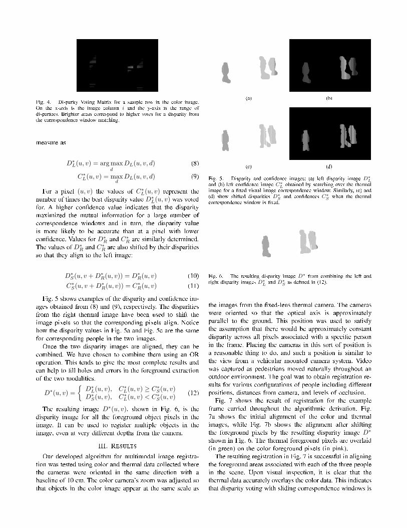
Fig. 4. Disparity Voting Matrix for a sample row in the color image.On the x-axis is the image column i and the y-axis is the range ofdisparities. Brighter areas correspond to higher votes for a disparity fromthe correspondence window matching.
measure as
D∗L(u, v) = arg max
dDL(u, v, d) (8)
C∗L(u, v) = maxd
DL(u, v, d) (9)
For a pixel (u, v) the values of C∗L(u, v) represent thenumber of times the best disparity value D∗
L(u, v) was votedfor. A higher con�dence value indicates that the disparitymaximized the mutual information for a large number ofcorrespondence windows and in turn, the disparity valueis more likely to be accurate than at a pixel with lowercon�dence. Values for D∗
R and C∗R are similarly determined.The values of D∗
R and C∗R are also shifted by their disparitiesso that they align to the left image:
D∗S(u, v + D∗
R(u, v)) = D∗R(u, v) (10)
C∗S(u, v + D∗R(u, v)) = C∗R(u, v) (11)
Fig. 5 shows examples of the disparity and con�dence im-ages obtained from (8) and (9), respectively. The disparitiesfrom the right thermal image have been used to shift theimage pixels so that the corresponding pixels align. Noticehow the disparity values in Fig. 5a and Fig. 5c are the samefor corresponding people in the two images.
Once the two disparity images are aligned, they can becombined. We have chosen to combine them using an ORoperation. This tends to give the most complete results andcan help to �ll holes and errors in the foreground extractionof the two modalities.
D∗(u, v) ={
D∗L(u, v), C∗L(u, v) ≥ C∗S(u, v)
D∗S(u, v), C∗L(u, v) < C∗S(u, v) (12)
The resulting image D∗(u, v), shown in Fig. 6, is thedisparity image for all the foreground object pixels in theimage. It can be used to register multiple objects in theimage, even at very different depths from the camera.
III. RESULTS
Our developed algorithm for multimodal image registra-tion was tested using color and thermal data collected wherethe cameras were oriented in the same direction with abaseline of 10 cm. The color camera's zoom was adjusted sothat objects in the color image appear at the same scale as
(a) (b)
(c) (d)
Fig. 5. Disparity and con�dence images: (a) left disparity image D∗Land (b) left con�dence image C∗L obtained by searching over the thermalimage for a �xed visual image correspondence window. Similarly, (c) and(d) show shifted disparities D∗S and con�dences C∗S when the thermalcorrespondence window is �xed.
Fig. 6. The resulting disparity image D∗ from combining the left andright disparity images D∗L and D∗S as de�ned in (12).
the images from the �xed-lens thermal camera. The cameraswere oriented so that the optical axis is approximatelyparallel to the ground. This position was used to satisfythe assumption that there would be approximately constantdisparity across all pixels associated with a speci�c personin the frame. Placing the cameras in this sort of position isa reasonable thing to do, and such a position is similar tothe view from a vehicular mounted camera system. Videowas captured as pedestrians moved naturally throughout anoutdoor environment. The goal was to obtain registration re-sults for various con�gurations of people including differentpositions, distances from camera, and levels of occlusion.
Fig. 7 shows the result of registration for the exampleframe carried throughout the algorithmic derivation. Fig.7a shows the initial alignment of the color and thermalimages, while Fig. 7b shows the alignment after shiftingthe foreground pixels by the resulting disparity image D∗
shown in Fig. 6. The thermal foreground pixels are overlaid(in green) on the color foreground pixels (in pink).
The resulting registration in Fig. 7 is successful in aligningthe foreground areas associated with each of the three peoplein the scene. Upon visual inspection, it is clear that thethermal data accurately overlays the color data. This indicatesthat disparity voting with sliding correspondence windows is
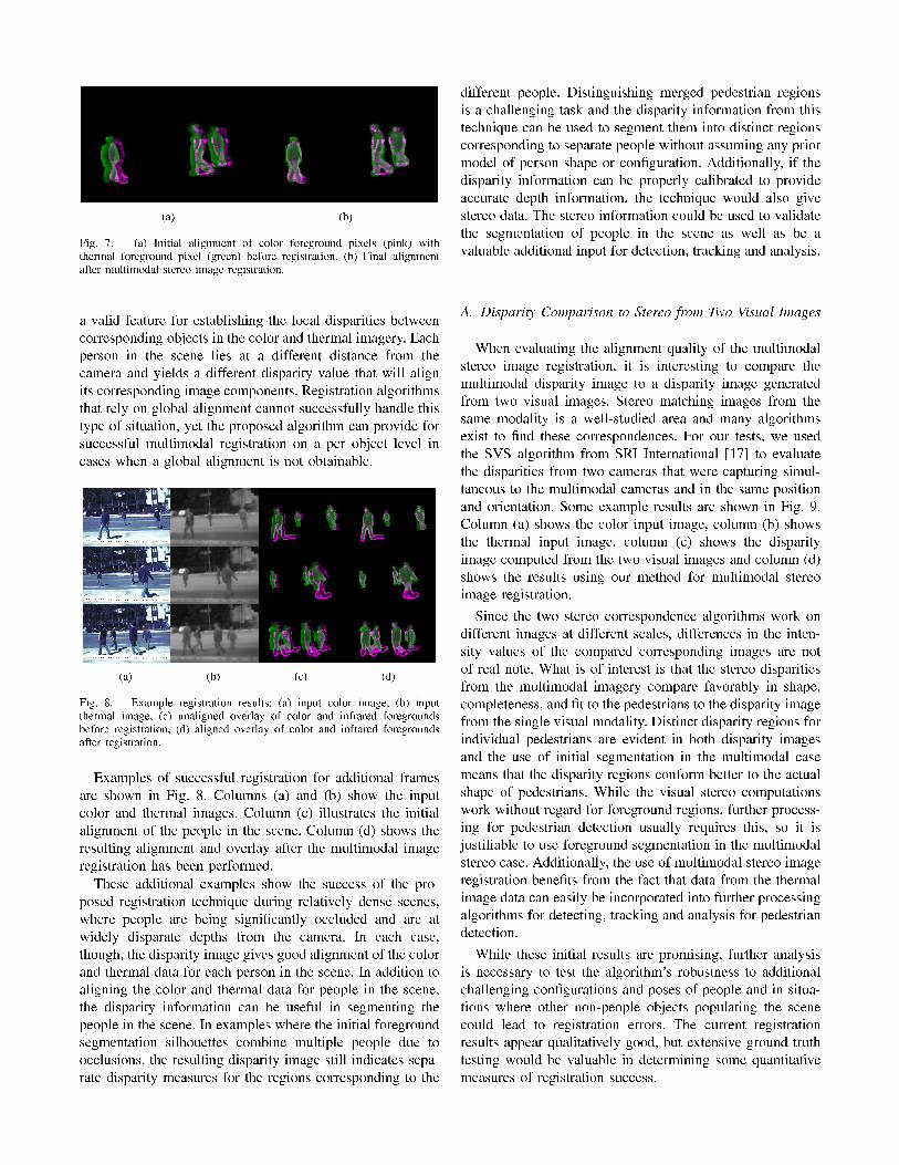
(a) (b)
Fig. 7. (a) Initial alignment of color foreground pixels (pink) withthermal foreground pixel (green) before registration. (b) Final alignmentafter multimodal stereo image registration.
a valid feature for establishing the local disparities betweencorresponding objects in the color and thermal imagery. Eachperson in the scene lies at a different distance from thecamera and yields a different disparity value that will alignits corresponding image components. Registration algorithmsthat rely on global alignment cannot successfully handle thistype of situation, yet the proposed algorithm can provide forsuccessful multimodal registration on a per object level incases when a global alignment is not obtainable.
(a) (b) (c) (d)
Fig. 8. Example registration results: (a) input color image, (b) inputthermal image, (c) unaligned overlay of color and infrared foregroundsbefore registration, (d) aligned overlay of color and infrared foregroundsafter registration.
Examples of successful registration for additional framesare shown in Fig. 8. Columns (a) and (b) show the inputcolor and thermal images. Column (c) illustrates the initialalignment of the people in the scene. Column (d) shows theresulting alignment and overlay after the multimodal imageregistration has been performed.
These additional examples show the success of the pro-posed registration technique during relatively dense scenes,where people are being signi�cantly occluded and are atwidely disparate depths from the camera. In each case,though, the disparity image gives good alignment of the colorand thermal data for each person in the scene. In addition toaligning the color and thermal data for people in the scene,the disparity information can be useful in segmenting thepeople in the scene. In examples where the initial foregroundsegmentation silhouettes combine multiple people due toocclusions, the resulting disparity image still indicates sepa-rate disparity measures for the regions corresponding to the
different people. Distinguishing merged pedestrian regionsis a challenging task and the disparity information from thistechnique can be used to segment them into distinct regionscorresponding to separate people without assuming any priormodel of person shape or con�guration. Additionally, if thedisparity information can be properly calibrated to provideaccurate depth information, the technique would also givestereo data. The stereo information could be used to validatethe segmentation of people in the scene as well as be avaluable additional input for detection, tracking and analysis.
A. Disparity Comparison to Stereo from Two Visual Images
When evaluating the alignment quality of the multimodalstereo image registration, it is interesting to compare themultimodal disparity image to a disparity image generatedfrom two visual images. Stereo matching images from thesame modality is a well-studied area and many algorithmsexist to �nd these correspondences. For our tests, we usedthe SVS algorithm from SRI International [17] to evaluatethe disparities from two cameras that were capturing simul-taneous to the multimodal cameras and in the same positionand orientation. Some example results are shown in Fig. 9.Column (a) shows the color input image, column (b) showsthe thermal input image, column (c) shows the disparityimage computed from the two visual images and column (d)shows the results using our method for multimodal stereoimage registration.
Since the two stereo correspondence algorithms work ondifferent images at different scales, differences in the inten-sity values of the compared corresponding images are notof real note. What is of interest is that the stereo disparitiesfrom the multimodal imagery compare favorably in shape,completeness, and �t to the pedestrians to the disparity imagefrom the single visual modality. Distinct disparity regions forindividual pedestrians are evident in both disparity imagesand the use of initial segmentation in the multimodal casemeans that the disparity regions conform better to the actualshape of pedestrians. While the visual stereo computationswork without regard for foreground regions, further process-ing for pedestrian detection usually requires this, so it isjusti�able to use foreground segmentation in the multimodalstereo case. Additionally, the use of multimodal stereo imageregistration bene�ts from the fact that data from the thermalimage data can easily be incorporated into further processingalgorithms for detecting, tracking and analysis for pedestriandetection.
While these initial results are promising, further analysisis necessary to test the algorithm's robustness to additionalchallenging con�gurations and poses of people and in situa-tions where other non-people objects populating the scenecould lead to registration errors. The current registrationresults appear qualitatively good, but extensive ground truthtesting would be valuable in determining some quantitativemeasures of registration success.
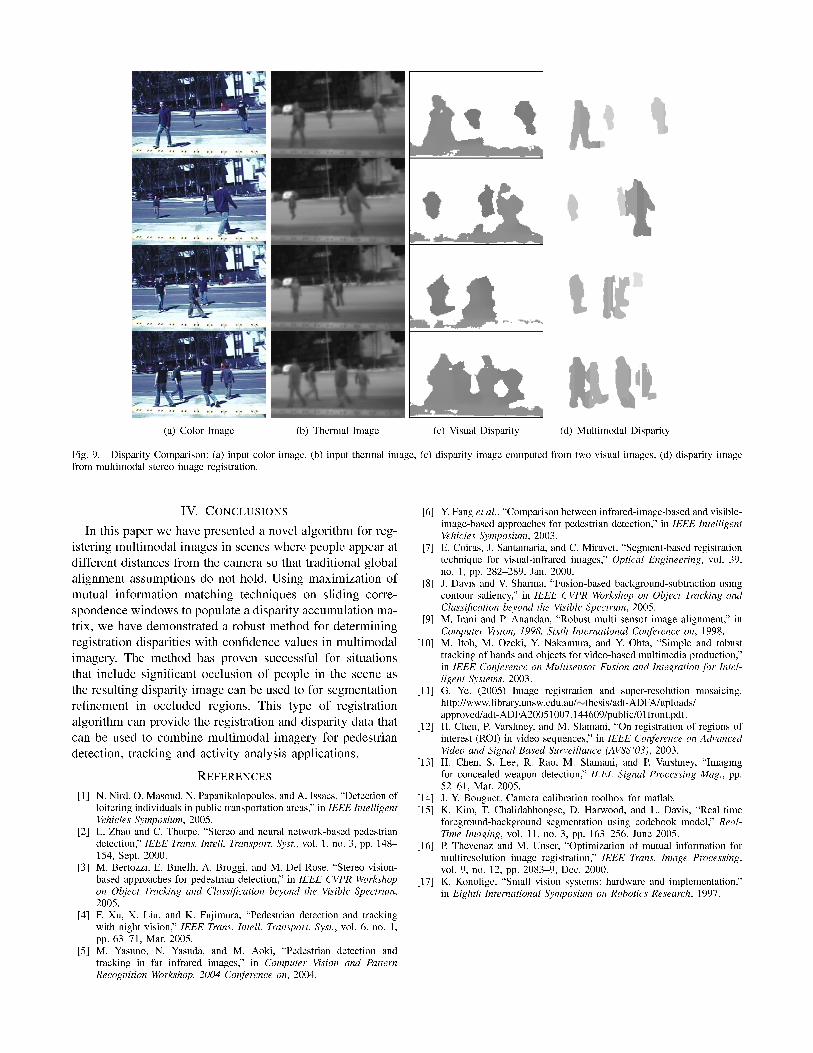
(a) Color Image (b) Thermal Image (c) Visual Disparity (d) Multimodal Disparity
Fig. 9. Disparity Comparison: (a) input color image, (b) input thermal image, (c) disparity image computed from two visual images, (d) disparity imagefrom multimodal stereo image registration.
IV. CONCLUSIONS
In this paper we have presented a novel algorithm for reg-istering multimodal images in scenes where people appear atdifferent distances from the camera so that traditional globalalignment assumptions do not hold. Using maximization ofmutual information matching techniques on sliding corre-spondence windows to populate a disparity accumulation ma-trix, we have demonstrated a robust method for determiningregistration disparities with con�dence values in multimodalimagery. The method has proven successful for situationsthat include signi�cant occlusion of people in the scene asthe resulting disparity image can be used to for segmentationre�nement in occluded regions. This type of registrationalgorithm can provide the registration and disparity data thatcan be used to combine multimodal imagery for pedestriandetection, tracking and activity analysis applications.
REFERENCES[1] N. Nird, O. Masoud, N. Papanikolopoulos, and A. Issacs, �Detection of
loitering individuals in public transportation areas,� in IEEE IntelligentVehicles Symposium, 2005.
[2] L. Zhao and C. Thorpe, �Stereo and neural network-based pedestriandetection,� IEEE Trans. Intell. Transport. Syst., vol. 1, no. 3, pp. 148�154, Sept. 2000.
[3] M. Bertozzi, E. Binelli, A. Broggi, and M. Del Rose, �Stereo vision-based approaches for pedestrian detection,� in IEEE CVPR Workshopon Object Tracking and Classi�cation beyond the Visible Spectrum,2005.
[4] F. Xu, X. Liu, and K. Fujimura, �Pedestrian detection and trackingwith night vision,� IEEE Trans. Intell. Transport. Syst., vol. 6, no. 1,pp. 63�71, Mar. 2005.
[5] M. Yasuno, N. Yasuda, and M. Aoki, �Pedestrian detection andtracking in far infrared images,� in Computer Vision and PatternRecognition Workshop, 2004 Conference on, 2004.
[6] Y. Fang et al., �Comparison between infrared-image-based and visible-image-based approaches for pedestrian detection,� in IEEE IntelligentVehicles Symposium, 2003.
[7] E. Coiras, J. Santamaria, and C. Miravet, �Segment-based registrationtechnique for visual-infrared images,� Optical Engineering, vol. 39,no. 1, pp. 282�289, Jan. 2000.
[8] J. Davis and V. Sharma, �Fusion-based background-subtraction usingcontour saliency,� in IEEE CVPR Workshop on Object Tracking andClassi�cation beyond the Visible Spectrum, 2005.
[9] M. Irani and P. Anandan, �Robust multi-sensor image alignment,� inComputer Vision, 1998. Sixth International Conference on, 1998.
[10] M. Itoh, M. Ozeki, Y. Nakamura, and Y. Ohta, �Simple and robusttracking of hands and objects for video-based multimedia production,�in IEEE Conference on Multisensor Fusion and Integration for Intel-ligent Systems, 2003.
[11] G. Ye. (2005) Image registration and super-resolution mosaicing.http://www.library.unsw.edu.au/∼thesis/adt-ADFA/uploads/approved/adt-ADFA20051007.144609/public/01front.pdf.
[12] H. Chen, P. Varshney, and M. Slamani, �On registration of regions ofinterest (ROI) in video sequences,� in IEEE Conference on AdvancedVideo and Signal Based Surveillance (AVSS'03), 2003.
[13] H. Chen, S. Lee, R. Rao, M. Slamani, and P. Varshney, �Imagingfor concealed weapon detection,� IEEE Signal Processing Mag., pp.52�61, Mar. 2005.
[14] J.-Y. Bouguet. Camera calibration toolbox for matlab.[15] K. Kim, T. Chalidabhongse, D. Harwood, and L. Davis, �Real-time
foreground-background segmentation using codebook model,� Real-Time Imaging, vol. 11, no. 3, pp. 163�256, June 2005.
[16] P. Thevenaz and M. Unser, �Optimization of mutual information formultiresolution image registration,� IEEE Trans. Image Processing,vol. 9, no. 12, pp. 2083�9, Dec. 2000.
[17] K. Konolige, �Small vision systems: hardware and implementation,�in Eighth International Symposium on Robotics Research, 1997.

![A New Benchmark for Stereo-Based Pedestrian Detection · of the well-known HOG-based pedestrian detector, e.g. [4], in both monocular and stereo vision set-ups. We assume our results](https://img.pdfslide.net/doc/110x75/5f61a2a48109d8100d34217f/a-new-benchmark-for-stereo-based-pedestrian-of-the-well-known-hog-based-pedestrian.jpg)
![IEEE TRANSACTIONS ON PATTERN ANALYSIS AND … Pedestrian Detection: Survey and Experiments ... cover both passive and active safety techniques, ... approaches using stereo vision [2],](https://img.pdfslide.net/doc/110x75/5b05379f7f8b9a41528d6ce8/ieee-transactions-on-pattern-analysis-and-pedestrian-detection-survey-and-experiments.jpg)
![A New Framework for Stereo Sensor Pose Through Road ...asappa/publications/J__IEEE_Trans... · pedestrian detection (e.g., [2] and [18]) only computes 3-D information over local maxima](https://img.pdfslide.net/doc/110x75/5f32a6f39c6ea66df54e95a1/a-new-framework-for-stereo-sensor-pose-through-road-asappapublicationsjieeetrans.jpg)