Embed Size (px)
Citation preview
MultiModem GSM/GPRS
External Wireless ModemData/Fax/Voice
MTCBA-G-F1MTCBA-G-F2
User Guide
User Guide for MultiModem GSM/GPRSExternal Data/Fax/Voice Wireless Modem
Models MTCBA-G-F1 & MTCBA-G-F2P/N S000304F, Revision F
Copyright © 2004 by Multi-Tech Systems, Inc.All rights reserved. This publication may not be reproduced, in whole or in part, without prior expressed writtenpermission from Multi-Tech Systems, Inc.Multi-Tech Systems, Inc. makes no representation or warranties with respect to the contents hereof and specificallydisclaims any implied warranties of merchantability or fitness for any particular purpose. Furthermore, Multi-TechSystems, Inc. reserves the right to revise this publication and to make changes from time to time in the content hereofwithout obligation of Multi-Tech Systems, Inc., to notify any person or organization of such revisions or changes.
Revision HistoryRevision Date DescriptionA 05/01/03 Initial ReleaseB 09/17/03 Revise package contents list & powering drawing.C 01/20/04 Revise package contents, add RS232 Connector pinout diagram.D 04/12/04 Revise package contents and features lists.E 07/13/04 Revise network access infoF 12/30/04 Revise package contents list & powering drawing and add 2 cable drawings.
Trademarks and LogosMulti-Tech, MultiMobile and the Multi-Tech logo are trademarks of Multi-Tech Systems, Inc. Windows is a registeredtrademark of Microsoft in the U.S. and other countries. Other trademarks and trade names mentioned in thispublication belong to their respective owners.
World HeadquartersMulti-Tech Systems, Inc.2205 Woodale Drive, Mounds View, Minnesota 55112(763) 785-3500; (800) 328-9717; Fax (763) 785-9874
Technical SupportCountry By Email By PhoneFrance: [email protected] (33) 1-64 61 09 81India: [email protected] 91 (124) 6340778U.K.: [email protected] (44) 118 959 7774U.S. and Canada: [email protected] (800) 972-2439Rest of the World: [email protected] (763) 717-5863
Internet Address: http://www.multitech.com
Contents
CHAPTER 1: PRODUCT DESCRIPTION AND SPECIFICATIONS .................................................................5
PRODUCT DESCRIPTION ..............................................................................................................................................5Package Contents ...................................................................................................................................................5Interfaces................................................................................................................................................................5Parts to be Supplied by Wireless Service Provider ................................................................................................5Parts to be Supplied by End User ..........................................................................................................................5Antenna/RF Specifications .....................................................................................................................................6AT Command Info ..................................................................................................................................................6Phone Number for the Wireless Modem.................................................................................................................6Network Access.......................................................................................................................................................6Features..................................................................................................................................................................7
APPLICATION OVERVIEW............................................................................................................................................8Application Types ...................................................................................................................................................8Benefits/Features in Applications...........................................................................................................................9Functions – GSM Modes ......................................................................................................................................10
SPECIFICATIONS........................................................................................................................................................11General Specifications ......................................................................................................................................11Electrical Characteristics ..................................................................................................................................11Input/output electrical characteristics for external connections..........................................................................11LED Indicators.....................................................................................................................................................12RS232 15-Pin Connector Pinout ..........................................................................................................................12
CHAPTER 2: INSTALLATION..............................................................................................................................13
MECHANICAL MOUNTING.........................................................................................................................................13ELECTRICAL INSTALLATION & CONFIGURATION ......................................................................................................15MOBILE PHONETOOLS...............................................................................................................................................18DIRECT MODEM INSTALLATION................................................................................................................................18VERIFYING SIGNAL STRENGTH .................................................................................................................................18VERIFYING NETWORK REGISTRATION ......................................................................................................................19TESTING THE CONFIGURATION .................................................................................................................................20
CHAPTER 3: TROUBLESHOOTING ...................................................................................................................21
TROUBLESHOOTING EXAMPLES ................................................................................................................................21Situation A: The modem does not answer through the serial link........................................................................21Situation B: The modem always returns «Error» when trying to issue a communication ...................................22Situation C: The modem always returns «No carrier» when trying to issue a communication ...........................23
CHAPTER 4: SAFETY ............................................................................................................................................24
SAFETY .....................................................................................................................................................................24General Safety ......................................................................................................................................................24Vehicle Safety .......................................................................................................................................................24Your Responsibility...............................................................................................................................................25
CHAPTER 5: WARRANTY AND REPAIRS ........................................................................................................26
Multi-Tech Warranty Statement ...........................................................................................................................26Repair Procedures for U.S. and Canadian Customers ........................................................................................26Repair Procedures for International Customers (Outside U.S.A. and Canada) ..................................................27Repair Procedures for International Distributors ...............................................................................................27Replacement Parts................................................................................................................................................27
CHAPTER 6: REFERENCE INFORMATION.....................................................................................................28
WIRELESS MODEM REFERENCE INFORMATION.........................................................................................................28General.................................................................................................................................................................28Disclaimer ............................................................................................................................................................28Data Cable Diagram, Regular Wireless MultiModem.........................................................................................28Data Cable Diagram, Wireless MultiModem with Voice.....................................................................................29
Chapter 1 – Description & Specifications
Multi-Tech Systems, Inc. MultiModem GSM/GPRS User Guide 5
Chapter 1: Product Description andSpecifications
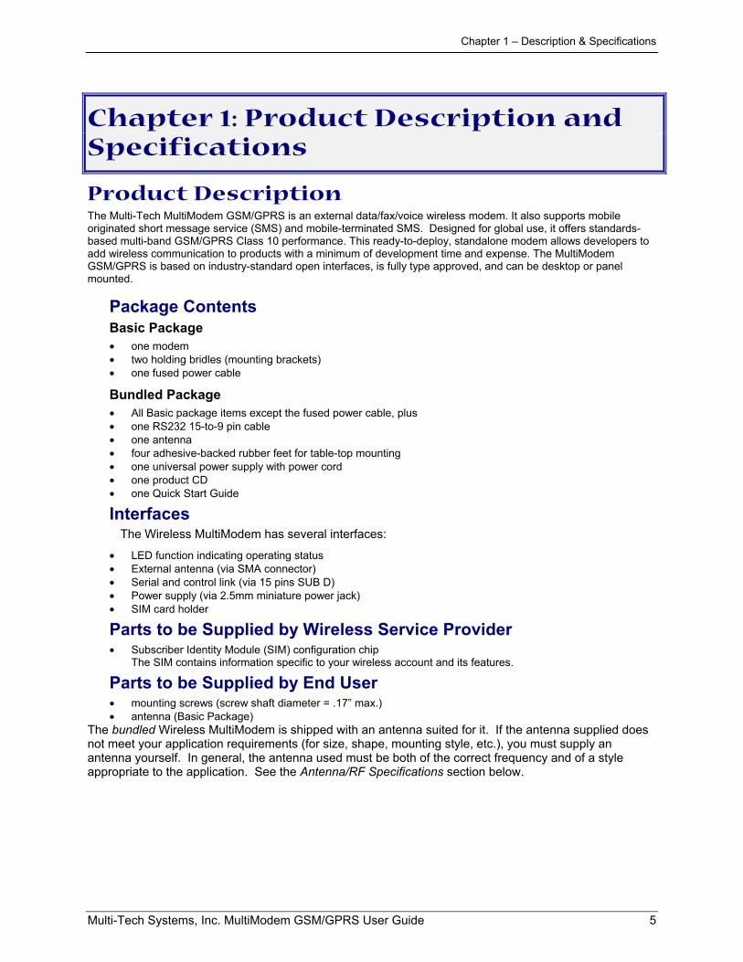
Product DescriptionThe Multi-Tech MultiModem GSM/GPRS is an external data/fax/voice wireless modem. It also supports mobileoriginated short message service (SMS) and mobile-terminated SMS. Designed for global use, it offers standards-based multi-band GSM/GPRS Class 10 performance. This ready-to-deploy, standalone modem allows developers toadd wireless communication to products with a minimum of development time and expense. The MultiModemGSM/GPRS is based on industry-standard open interfaces, is fully type approved, and can be desktop or panelmounted.
Package ContentsBasic Package• one modem• two holding bridles (mounting brackets)• one fused power cable
Bundled Package• All Basic package items except the fused power cable, plus• one RS232 15-to-9 pin cable• one antenna• four adhesive-backed rubber feet for table-top mounting• one universal power supply with power cord• one product CD• one Quick Start Guide
InterfacesThe Wireless MultiModem has several interfaces:
• LED function indicating operating status• External antenna (via SMA connector)• Serial and control link (via 15 pins SUB D)• Power supply (via 2.5mm miniature power jack)• SIM card holder
Parts to be Supplied by Wireless Service Provider• Subscriber Identity Module (SIM) configuration chip
The SIM contains information specific to your wireless account and its features.
Parts to be Supplied by End User• mounting screws (screw shaft diameter = .17” max.)• antenna (Basic Package)
The bundled Wireless MultiModem is shipped with an antenna suited for it. If the antenna supplied doesnot meet your application requirements (for size, shape, mounting style, etc.), you must supply anantenna yourself. In general, the antenna used must be both of the correct frequency and of a styleappropriate to the application. See the Antenna/RF Specifications section below.
Chapter 1 – Description & Specifications
Multi-Tech Systems, Inc. MultiModem GSM/GPRS User Guide 6
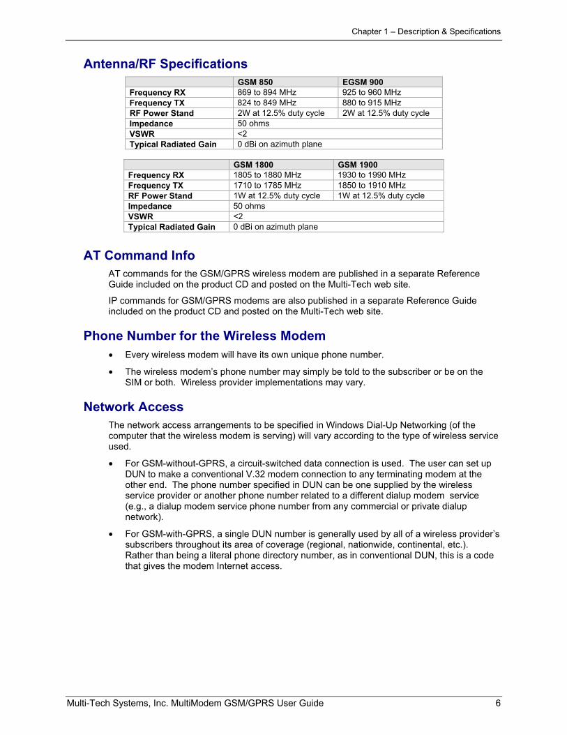
Antenna/RF SpecificationsGSM 850 EGSM 900
Frequency RX 869 to 894 MHz 925 to 960 MHzFrequency TX 824 to 849 MHz 880 to 915 MHzRF Power Stand 2W at 12.5% duty cycle 2W at 12.5% duty cycleImpedance 50 ohmsVSWR <2Typical Radiated Gain 0 dBi on azimuth plane
GSM 1800 GSM 1900Frequency RX 1805 to 1880 MHz 1930 to 1990 MHzFrequency TX 1710 to 1785 MHz 1850 to 1910 MHzRF Power Stand 1W at 12.5% duty cycle 1W at 12.5% duty cycleImpedance 50 ohmsVSWR <2Typical Radiated Gain 0 dBi on azimuth plane
AT Command InfoAT commands for the GSM/GPRS wireless modem are published in a separate ReferenceGuide included on the product CD and posted on the Multi-Tech web site.
IP commands for GSM/GPRS modems are also published in a separate Reference Guideincluded on the product CD and posted on the Multi-Tech web site.
Phone Number for the Wireless Modem• Every wireless modem will have its own unique phone number.
• The wireless modem’s phone number may simply be told to the subscriber or be on theSIM or both. Wireless provider implementations may vary.
Network AccessThe network access arrangements to be specified in Windows Dial-Up Networking (of thecomputer that the wireless modem is serving) will vary according to the type of wireless serviceused.
• For GSM-without-GPRS, a circuit-switched data connection is used. The user can set upDUN to make a conventional V.32 modem connection to any terminating modem at theother end. The phone number specified in DUN can be one supplied by the wirelessservice provider or another phone number related to a different dialup modem service(e.g., a dialup modem service phone number from any commercial or private dialupnetwork).
• For GSM-with-GPRS, a single DUN number is generally used by all of a wireless provider’ssubscribers throughout its area of coverage (regional, nationwide, continental, etc.).Rather than being a literal phone directory number, as in conventional DUN, this is a codethat gives the modem Internet access.
Chapter 1 – Description & Specifications
Multi-Tech Systems, Inc. MultiModem GSM/GPRS User Guide 7
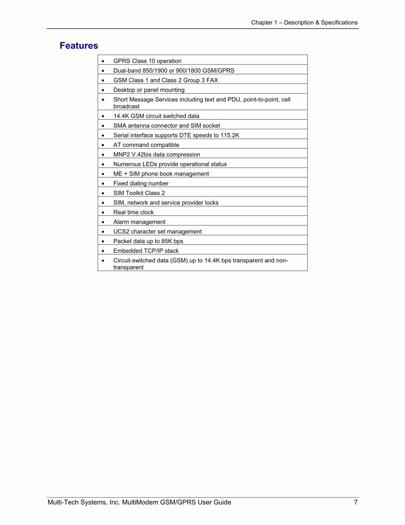
Features• GPRS Class 10 operation• Dual-band 850/1900 or 900/1800 GSM/GPRS• GSM Class 1 and Class 2 Group 3 FAX• Desktop or panel mounting• Short Message Services including text and PDU, point-to-point, cell
broadcast• 14.4K GSM circuit switched data• SMA antenna connector and SIM socket• Serial interface supports DTE speeds to 115.2K• AT command compatible• MNP2 V.42bis data compression• Numerous LEDs provide operational status• ME + SIM phone book management• Fixed dialing number• SIM Toolkit Class 2• SIM, network and service provider locks• Real time clock• Alarm management• UCS2 character set management• Packet data up to 85K bps• Embedded TCP/IP stack• Circuit-switched data (GSM) up to 14.4K bps transparent and non-
transparent
Chapter 1 – Description & Specifications
Multi-Tech Systems, Inc. MultiModem GSM/GPRS User Guide 8
Application Overview
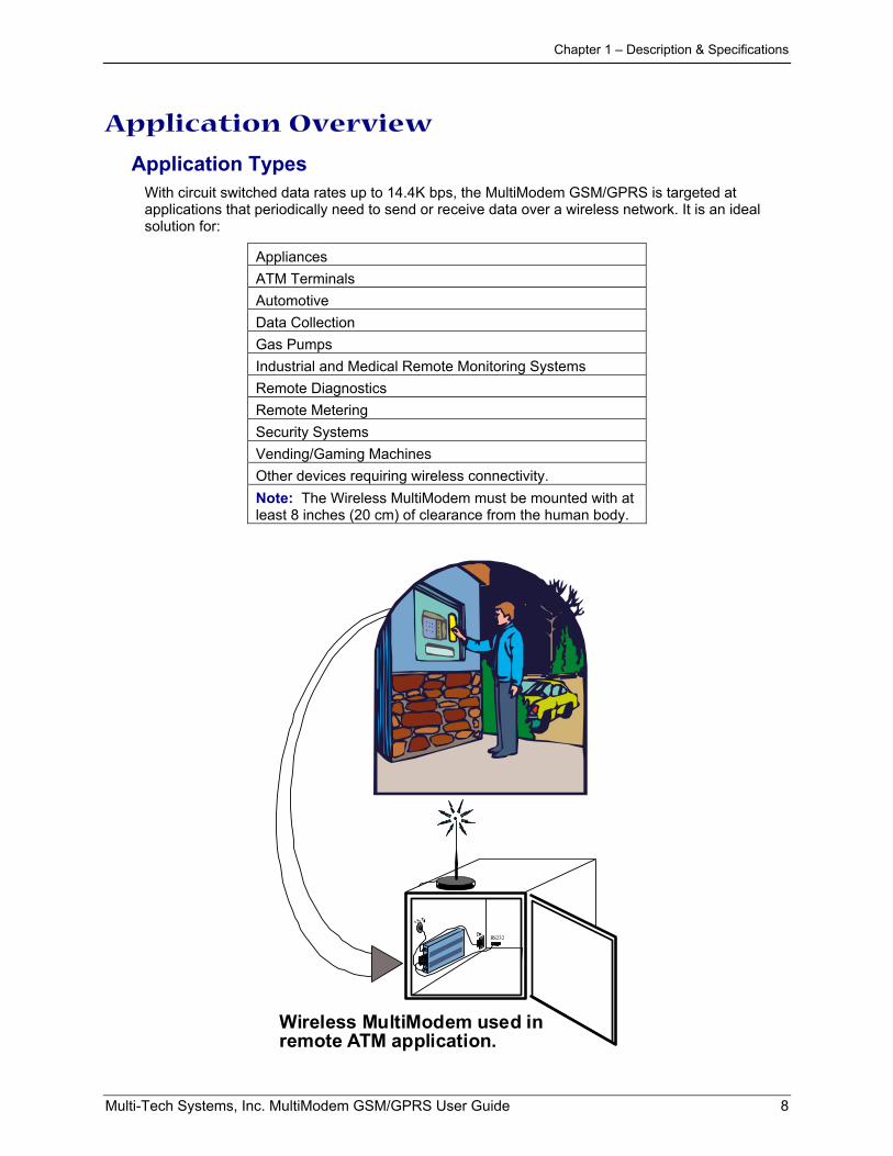
Application TypesWith circuit switched data rates up to 14.4K bps, the MultiModem GSM/GPRS is targeted atapplications that periodically need to send or receive data over a wireless network. It is an idealsolution for:
AppliancesATM TerminalsAutomotiveData CollectionGas PumpsIndustrial and Medical Remote Monitoring SystemsRemote DiagnosticsRemote MeteringSecurity SystemsVending/Gaming MachinesOther devices requiring wireless connectivity.Note: The Wireless MultiModem must be mounted with atleast 8 inches (20 cm) of clearance from the human body.
RS232
Wireless MultiModem used inremote ATM application.
Chapter 1 – Description & Specifications
Multi-Tech Systems, Inc. MultiModem GSM/GPRS User Guide 9
Benefits/Features in ApplicationsShort Development Time. The MultiModem GSM/ GPRS can make your existing and nextgeneration device, machine, or system, communication-ready without requiring any hardwarechanges to its design. It actually provides faster time-to-market because it relieves the burden andexpense of obtaining network and RF approvals. This complete, ready-to-deploy wireless modemallows you to enhance your product while you focus on developing its core features.Voice Features. The MultiModem GSM/GPRS provides telephony and Dual Tone Multi Frequency(DTMF) functionality. It also allows for emergency calls as well as echo cancellation and noisereduction (option), and full rate, enhanced Full Rate and Half Rate (FR/EFR/HR).Short Message Services. The MultiModem GSM/GPRS offers SMS features such as text andPDU, point-to-point (MT/MO) and cell broadcast.Compatible Supplementary Services. The MultiModem GSM/GPRS is compatible withsupplementary services such as call forwarding, call barring, multiparty, call waiting and call hold,calling line identification, advice of charge, USSD, closed user group and explicit call transfer.Management Features. The MultiModem GSM/GPRS provides advanced management featuresincluding phone book management, fixed dialing number, and real time clock and alarmmanagement.Industry-standard Modem Commands. The MultiModem GSM/GPRS provides industry-standardAT-style commands for ease of integration into your existing software application.Industrial Chassis. The MultiModem GSM/GPRS is packaged in a rugged, water resistant,industrial chassis. The chassis has an RS-232 DE-15 Voice/Data interface connector and apermanent screw-type power connector. It also has an SMA antenna connector. The chassis canbe side-mounted on a panel or top-mounted on a desktop or other surface. A set of LEDs indicatesthe modem’s operational status.Packet-Switched Data. The MultiModem GSM/GPRS supports GPRS Class 10 packet-switchedcellular data. This enables mobile Internet functionality by allowing interworking between theexisting Internet and the cellular network at speeds up to 85K bps. Any service that is used overthe fixed Internet today – File Transfer Protocol (FTP), web browsing, chat, e-mail, telnet -- isavailable over the cellular network, as well. The MultiModem GSM/GPRS supports PBCCH andcoding schemes CS1 to CS4, and is compliant with SMG31bis.Circuit-Switched Data (CSD). The MultiModem GSM/GPRS also supports GSM circuit-switchedcellular data connections. Circuit-switched data connections support speeds up to 14.4K bps,Class 1 and Class 2 Group 3 fax, as well as MNP2 V.42bis compression. CSD cellular wirelessconnections are ideal for applications that require a quick wireless replacement of an existing point-to-point analog dial-up connection. They integrate seamlessly with your current applicationrequiring little infrastructure change.Internet-Enabled. The MultiModem GSM/GPRS includes an embedded TCP/IP protocol stack tobring Internet connectivity to any device. Using the embedded Internet protocols and the wirlessconnection to an IP network, it sends and receives data over the Internet. It can also serve a singleweb page in response to a web browser request.
Chapter 1 – Description & Specifications
Multi-Tech Systems, Inc. MultiModem GSM/GPRS User Guide 10
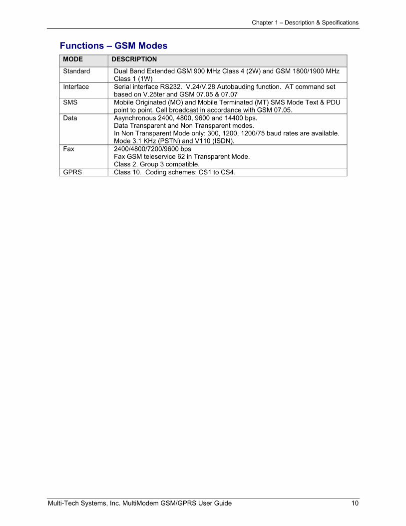
Functions – GSM ModesMODE DESCRIPTION
Standard Dual Band Extended GSM 900 MHz Class 4 (2W) and GSM 1800/1900 MHzClass 1 (1W)
Interface Serial interface RS232. V.24/V.28 Autobauding function. AT command setbased on V.25ter and GSM 07.05 & 07.07
SMS Mobile Originated (MO) and Mobile Terminated (MT) SMS Mode Text & PDUpoint to point. Cell broadcast in accordance with GSM 07.05.
Data Asynchronous 2400, 4800, 9600 and 14400 bps.Data Transparent and Non Transparent modes.In Non Transparent Mode only: 300, 1200, 1200/75 baud rates are available.Mode 3.1 KHz (PSTN) and V110 (ISDN).
Fax 2400/4800/7200/9600 bpsFax GSM teleservice 62 in Transparent Mode.Class 2. Group 3 compatible.
GPRS Class 10. Coding schemes: CS1 to CS4.
Chapter 1 – Description & Specifications
Multi-Tech Systems, Inc. MultiModem GSM/GPRS User Guide 11
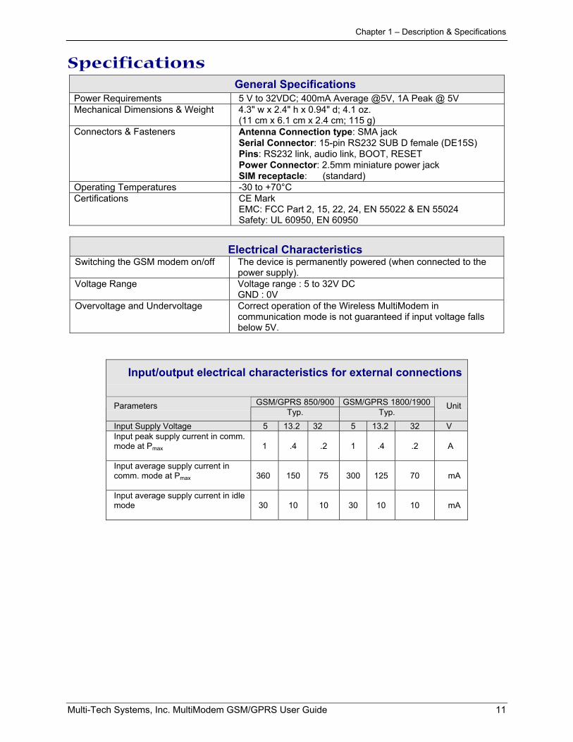
SpecificationsGeneral Specifications
Power Requirements 5 V to 32VDC; 400mA Average @5V, 1A Peak @ 5VMechanical Dimensions & Weight 4.3" w x 2.4" h x 0.94" d; 4.1 oz.
(11 cm x 6.1 cm x 2.4 cm; 115 g)Connectors & Fasteners Antenna Connection type: SMA jack
Serial Connector: 15-pin RS232 SUB D female (DE15S)Pins: RS232 link, audio link, BOOT, RESETPower Connector: 2.5mm miniature power jackSIM receptacle: (standard)
Operating Temperatures -30 to +70°CCertifications CE Mark
EMC: FCC Part 2, 15, 22, 24, EN 55022 & EN 55024Safety: UL 60950, EN 60950
Electrical CharacteristicsSwitching the GSM modem on/off The device is permanently powered (when connected to the
power supply).Voltage Range Voltage range : 5 to 32V DC
GND : 0VOvervoltage and Undervoltage Correct operation of the Wireless MultiModem in
communication mode is not guaranteed if input voltage fallsbelow 5V.
Input/output electrical characteristics for external connections
GSM/GPRS 850/900 GSM/GPRS 1800/1900ParametersTyp. Typ.
Unit
Input Supply Voltage 5 13.2 32 5 13.2 32 VInput peak supply current in comm.mode at Pmax 1 .4 .2 1 .4 .2 A
Input average supply current incomm. mode at Pmax 360 150 75 300 125 70 mA
Input average supply current in idlemode 30 10 10 30 10 10 mA
Chapter 1 – Description & Specifications
Multi-Tech Systems, Inc. MultiModem GSM/GPRS User Guide 12
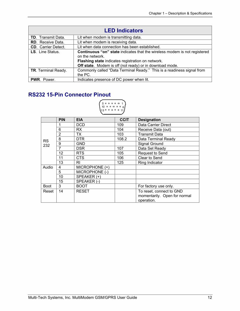
LED IndicatorsTD. Transmit Data. Lit when modem is transmitting data.RD. Receive Data. Lit when modem is receiving data.CD. Carrier Detect. Lit when data connection has been established.LS. Line Status. Continuous “on” state indicates that the wireless modem is not registered
on the network.Flashing state indicates registration on network.Off state. Modem is off (not ready) or in download mode.
TR. Terminal Ready. Commonly called “Data Terminal Ready.” This is a readiness signal fromthe PC.
PWR. Power. Indicates presence of DC power when lit.
RS232 15-Pin Connector Pinout
1011
615
15
PIN EIA CCIT Designation1 DCD 109 Data Carrier Direct6 RX 104 Receive Data (out)2 TX 103 Transmit Data8 DTR 108.2 Data Terminal Ready9 GND Signal Ground7 DSR 107 Data Set Ready12 RTS 105 Request to Send11 CTS 106 Clear to Send
RS232
13 RI 125 Ring Indicator4 MICROPHONE (+)5 MICROPHONE (-)10 SPEAKER (+)
Audio
15 SPEAKER (-)Boot 3 BOOT For factory use only.Reset 14 RESET To reset, connect to GND
momentarily. Open for normaloperation.
Chapter 2 – Installation
Multi-Tech Systems, Inc. MultiModem GSM/GPRS User Guide 13
Chapter 2: Installation
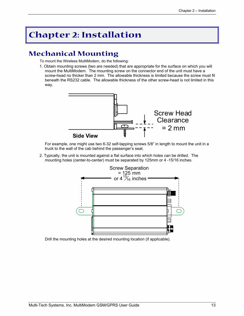
Mechanical MountingTo mount the Wireless MultiModem, do the following:1. Obtain mounting screws (two are needed) that are appropriate for the surface on which you will
mount the MultiModem. The mounting screw on the connector end of the unit must have ascrew-head no thicker than 2 mm. The allowable thickness is limited because the screw must fitbeneath the RS232 cable. The allowable thickness of the other screw-head is not limited in thisway.
= 2 mm
Screw HeadClearance
Side ViewFor example, one might use two 6-32 self-tapping screws 5/8” in length to mount the unit in atruck to the wall of the cab behind the passenger’s seat.
2. Typically, the unit is mounted against a flat surface into which holes can be drilled. Themounting holes (center-to-center) must be separated by 125mm or 4 -15/16 inches.
Screw Separation= 125 mm
or 41516 inches
Drill the mounting holes at the desired mounting location (if applicable).
Chapter 2 – Installation
Multi-Tech Systems, Inc. MultiModem GSM/GPRS User Guide 14
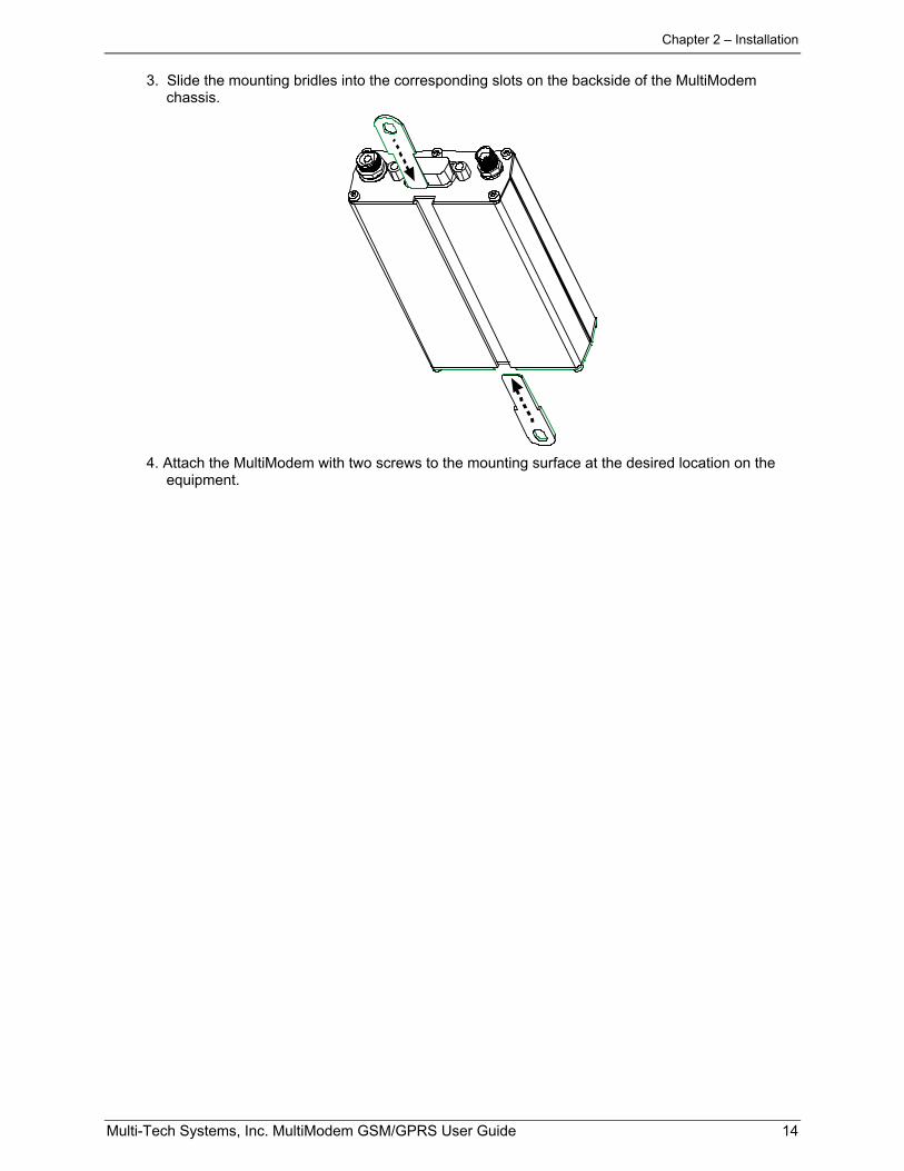
3. Slide the mounting bridles into the corresponding slots on the backside of the MultiModemchassis.
4. Attach the MultiModem with two screws to the mounting surface at the desired location on theequipment.
Chapter 2 – Installation
Multi-Tech Systems, Inc. MultiModem GSM/GPRS User Guide 15
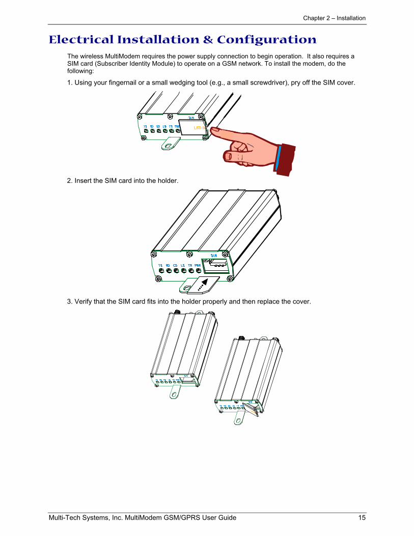
Electrical Installation & ConfigurationThe wireless MultiModem requires the power supply connection to begin operation. It also requires aSIM card (Subscriber Identity Module) to operate on a GSM network. To install the modem, do thefollowing:
1. Using your fingernail or a small wedging tool (e.g., a small screwdriver), pry off the SIM cover.
2. Insert the SIM card into the holder.
3. Verify that the SIM card fits into the holder properly and then replace the cover.
Chapter 2 – Installation
Multi-Tech Systems, Inc. MultiModem GSM/GPRS User Guide 16
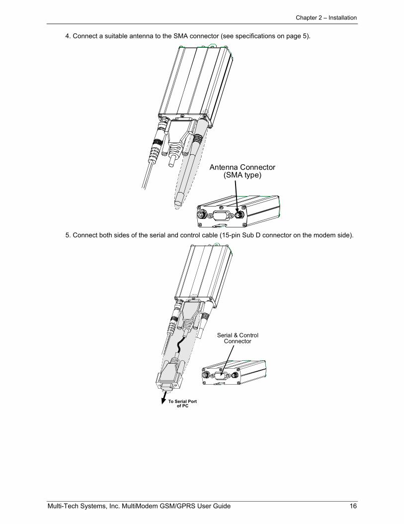
4. Connect a suitable antenna to the SMA connector (see specifications on page 5).
Antenna Connector(SMA type)
5. Connect both sides of the serial and control cable (15-pin Sub D connector on the modem side).
Serial & ControlConnector
To Serial Portof PC
Chapter 2 – Installation
Multi-Tech Systems, Inc. MultiModem GSM/GPRS User Guide 17
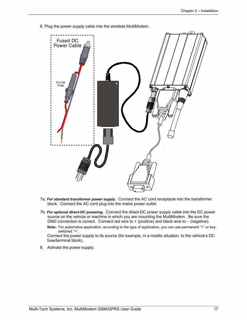
6. Plug the power supply cable into the wireless MultiModem.
Fused DCPower Cable
In-LineFuse
7a. For standard transformer power supply. Connect the AC cord receptacle into the transformerblock. Connect the AC cord plug into the mains power outlet.
7b. For optional direct-DC powering. Connect the direct-DC power supply cable into the DC powersource on the vehicle or machine in which you are mounting the MultiModem. Be sure theGND connection is correct. Connect red wire to + (positive) and black wire to – (negative).Note: For automotive application: according to the type of application, you can use permanent “+” or key-
switched “+”.Connect the power supply to its source (for example, in a mobile situation, to the vehicle’s DCfuse/terminal block).
8. Activate the power supply.
Chapter 2 – Installation
Multi-Tech Systems, Inc. MultiModem GSM/GPRS User Guide 18
Mobile PhonetoolsFor initial configuration of your wireless device, Multi-Tech offers a Windows based mobile PhoneTools application.To load mobile Phone Tools, click on the mobile Phone Tools icon on your system CD and followthe on-screen prompts.
Direct Modem InstallationTo install the Wireless MultiModem directly into the computer's Windows OS so it is independent of themobile Phonetools program, use the "Add Modem" command or equivalent for your OS. During thisinstallation, you will need to browse to the MultiModem's INF file (using the “Have Disk” option in theinstallation process). This INF file is in the root directory of the Product CD.
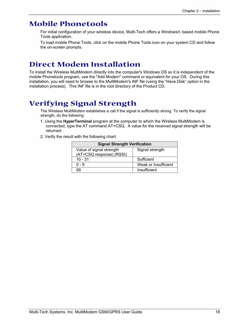
Verifying Signal StrengthThe Wireless MultiModem establishes a call if the signal is sufficiently strong. To verify the signalstrength, do the following:1. Using the HyperTerminal program at the computer to which the Wireless MultiModem is
connected, type the AT command AT+CSQ. A value for the received signal strength will bereturned.
2. Verify the result with the following chart:
Signal Strength VerificationValue of signal strength(AT+CSQ response) (RSSI)
Signal strength
10 - 31 Sufficient0 - 9 Weak or Insufficient99 Insufficient
Chapter 2 – Installation
Multi-Tech Systems, Inc. MultiModem GSM/GPRS User Guide 19
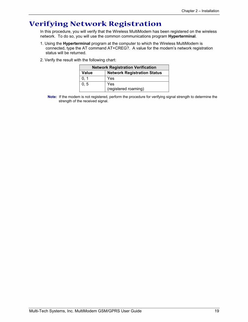
Verifying Network RegistrationIn this procedure, you will verify that the Wireless MultiModem has been registered on the wirelessnetwork. To do so, you will use the common communications program Hyperterminal.
1. Using the Hyperterminal program at the computer to which the Wireless MultiModem isconnected, type the AT command AT+CREG?. A value for the modem’s network registrationstatus will be returned.
2. Verify the result with the following chart:
Network Registration VerificationValue Network Registration Status0, 1 Yes0, 5 Yes
(registered roaming)
Note: If the modem is not registered, perform the procedure for verifying signal strength to determine thestrength of the received signal.
Chapter 2 – Installation
Multi-Tech Systems, Inc. MultiModem GSM/GPRS User Guide 20
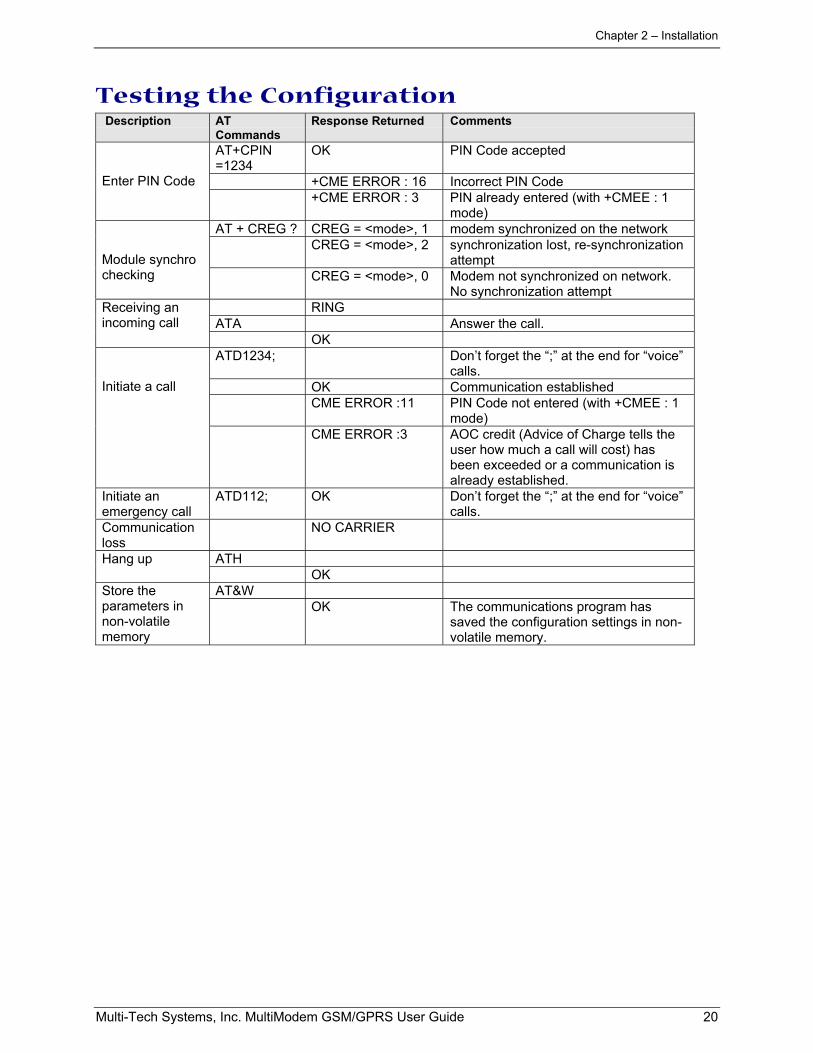
Testing the Configuration Description AT
CommandsResponse Returned Comments
AT+CPIN=1234
OK PIN Code accepted
+CME ERROR : 16 Incorrect PIN CodeEnter PIN Code+CME ERROR : 3 PIN already entered (with +CMEE : 1
mode)AT + CREG ? CREG = <mode>, 1 modem synchronized on the network
CREG = <mode>, 2 synchronization lost, re-synchronizationattemptModule synchro
checking CREG = <mode>, 0 Modem not synchronized on network.No synchronization attempt
RINGATA Answer the call.
Receiving anincoming call
OKATD1234; Don’t forget the “;” at the end for “voice”
calls.OK Communication establishedCME ERROR :11 PIN Code not entered (with +CMEE : 1
mode)
Initiate a call
CME ERROR :3 AOC credit (Advice of Charge tells theuser how much a call will cost) hasbeen exceeded or a communication isalready established.
Initiate anemergency call
ATD112; OK Don’t forget the “;” at the end for “voice”calls.
Communicationloss
NO CARRIER
ATHHang upOK
AT&WStore theparameters innon-volatilememory
OK The communications program hassaved the configuration settings in non-volatile memory.
Chapter 4 – Safety
Multi-Tech Systems, Inc. MultiModem GSM/GPRS User Guide 21
Chapter 3: Troubleshooting
Troubleshooting Examples
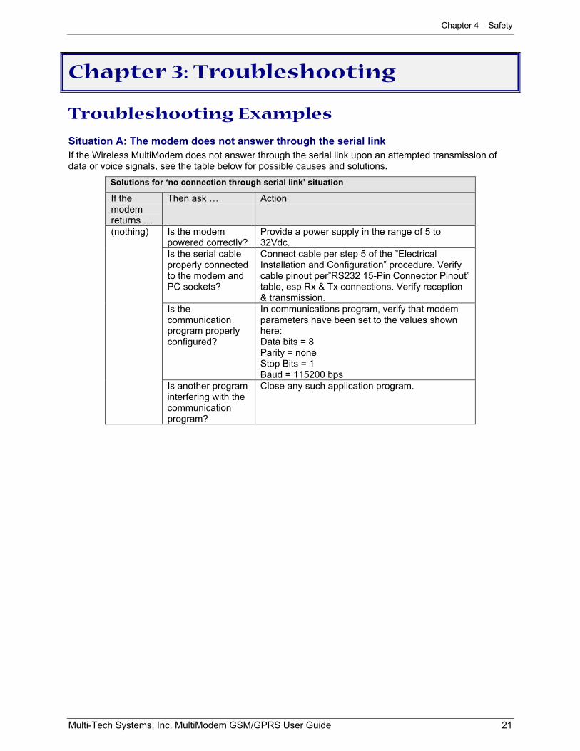
Situation A: The modem does not answer through the serial linkIf the Wireless MultiModem does not answer through the serial link upon an attempted transmission ofdata or voice signals, see the table below for possible causes and solutions.
Solutions for ‘no connection through serial link’ situation
If themodemreturns …
Then ask … Action
Is the modempowered correctly?
Provide a power supply in the range of 5 to32Vdc.
Is the serial cableproperly connectedto the modem andPC sockets?
Connect cable per step 5 of the ”ElectricalInstallation and Configuration” procedure. Verifycable pinout per”RS232 15-Pin Connector Pinout”table, esp Rx & Tx connections. Verify reception& transmission.
Is thecommunicationprogram properlyconfigured?
In communications program, verify that modemparameters have been set to the values shownhere:Data bits = 8Parity = noneStop Bits = 1Baud = 115200 bps
(nothing)
Is another programinterfering with thecommunicationprogram?
Close any such application program.
Chapter 4 – Safety
Multi-Tech Systems, Inc. MultiModem GSM/GPRS User Guide 22
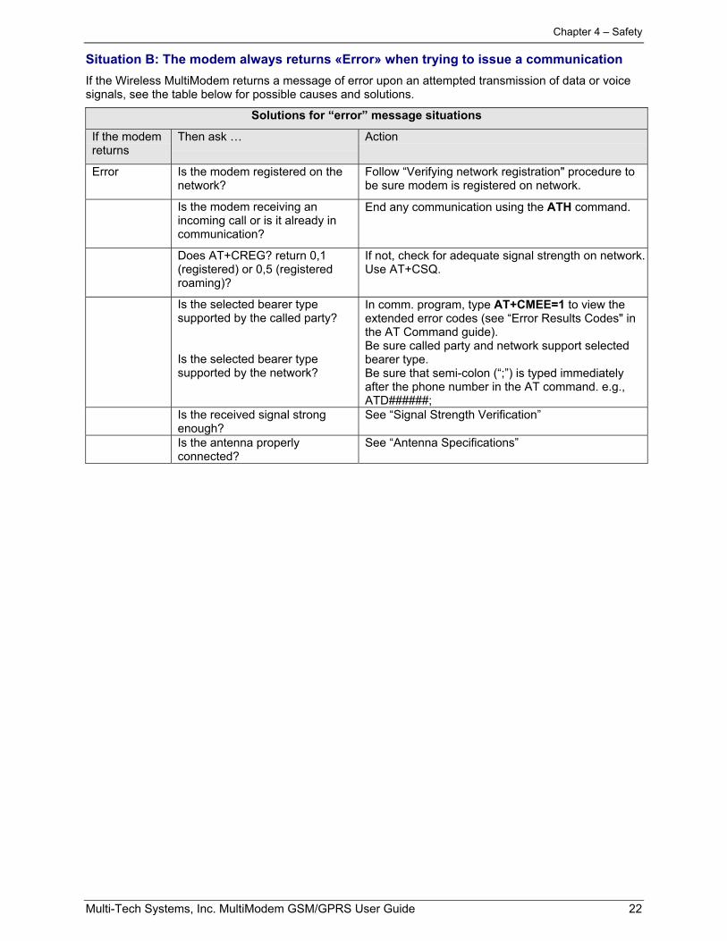
Situation B: The modem always returns «Error» when trying to issue a communicationIf the Wireless MultiModem returns a message of error upon an attempted transmission of data or voicesignals, see the table below for possible causes and solutions.
Solutions for “error” message situations
If the modemreturns
Then ask … Action
Error Is the modem registered on thenetwork?
Follow “Verifying network registration" procedure tobe sure modem is registered on network.
Is the modem receiving anincoming call or is it already incommunication?
End any communication using the ATH command.
Does AT+CREG? return 0,1(registered) or 0,5 (registeredroaming)?
If not, check for adequate signal strength on network.Use AT+CSQ.
Is the selected bearer typesupported by the called party?
Is the selected bearer typesupported by the network?
In comm. program, type AT+CMEE=1 to view theextended error codes (see “Error Results Codes" inthe AT Command guide).Be sure called party and network support selectedbearer type.Be sure that semi-colon (“;”) is typed immediatelyafter the phone number in the AT command. e.g.,ATD######;
Is the received signal strongenough?
See “Signal Strength Verification”
Is the antenna properlyconnected?
See “Antenna Specifications”
Chapter 4 – Safety
Multi-Tech Systems, Inc. MultiModem GSM/GPRS User Guide 23
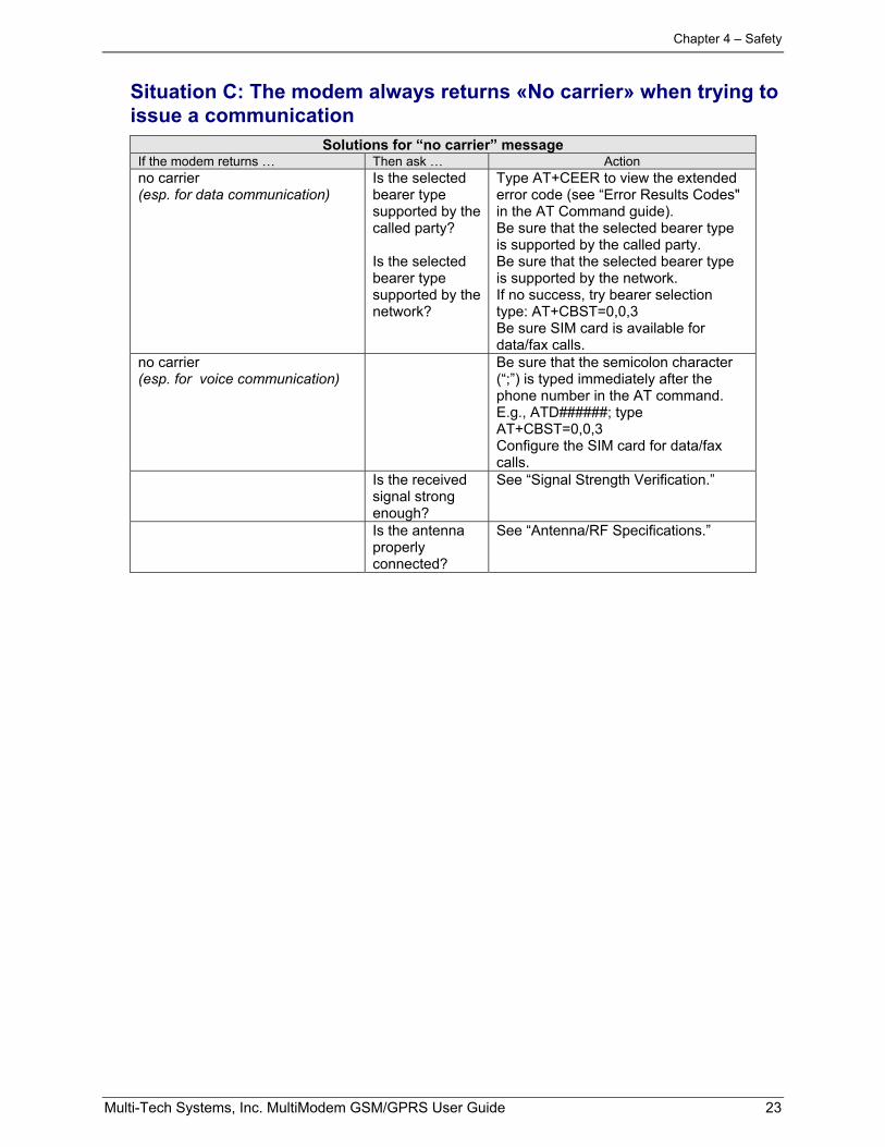
Situation C: The modem always returns «No carrier» when trying toissue a communication
Solutions for “no carrier” messageIf the modem returns … Then ask … Actionno carrier(esp. for data communication)
Is the selectedbearer typesupported by thecalled party?
Is the selectedbearer typesupported by thenetwork?
Type AT+CEER to view the extendederror code (see “Error Results Codes"in the AT Command guide).Be sure that the selected bearer typeis supported by the called party.Be sure that the selected bearer typeis supported by the network.If no success, try bearer selectiontype: AT+CBST=0,0,3Be sure SIM card is available fordata/fax calls.
no carrier(esp. for voice communication)
Be sure that the semicolon character(“;”) is typed immediately after thephone number in the AT command.E.g., ATD######; typeAT+CBST=0,0,3Configure the SIM card for data/faxcalls.
Is the receivedsignal strongenough?
See “Signal Strength Verification.”
Is the antennaproperlyconnected?
See “Antenna/RF Specifications.”
Chapter 4 – Safety
Multi-Tech Systems, Inc. MultiModem GSM/GPRS User Guide 24
Chapter 4: Safety
Safety
General Safety
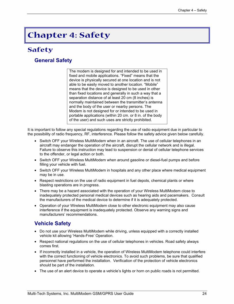
The modem is designed for and intended to be used infixed and mobile applications. “Fixed” means that thedevice is physically secured at one location and is notable to be easily moved to another location. “Mobile”means that the device is designed to be used in otherthan fixed locations and generally in such a way that aseparation distance of at least 20 cm (8 inches) isnormally maintained between the transmitter’s antennaand the body of the user or nearby persons. TheModem is not designed for or intended to be used inportable applications (within 20 cm. or 8 in. of the bodyof the user) and such uses are strictly prohibited.
It is important to follow any special regulations regarding the use of radio equipment due in particular tothe possibility of radio frequency, RF, interference. Please follow the safety advice given below carefully.
• Switch OFF your Wireless MultiModem when in an aircraft. The use of cellular telephones in anaircraft may endanger the operation of the aircraft, disrupt the cellular network and is illegal.Failure to observe this instruction may lead to suspension or denial of cellular telephone servicesto the offender, or legal action or both.
• Switch OFF your Wireless MultiModem when around gasoline or diesel-fuel pumps and beforefilling your vehicle with fuel.
• Switch OFF your Wireless MultiModem in hospitals and any other place where medical equipmentmay be in use.
• Respect restrictions on the use of radio equipment in fuel depots, chemical plants or whereblasting operations are in progress.
• There may be a hazard associated with the operation of your Wireless MultiModem close toinadequately protected personal medical devices such as hearing aids and pacemakers. Consultthe manufacturers of the medical device to determine if it is adequately protected.
• Operation of your Wireless MultiModem close to other electronic equipment may also causeinterference if the equipment is inadequately protected. Observe any warning signs andmanufacturers’ recommendations.
Vehicle Safety• Do not use your Wireless MultiModem while driving, unless equipped with a correctly installed
vehicle kit allowing ‘Hands-Free’ Operation.• Respect national regulations on the use of cellular telephones in vehicles. Road safety always
comes first.• If incorrectly installed in a vehicle, the operation of Wireless MultiModem telephone could interfere
with the correct functioning of vehicle electronics. To avoid such problems, be sure that qualifiedpersonnel have performed the installation. Verification of the protection of vehicle electronicsshould be part of the installation.
• The use of an alert device to operate a vehicle’s lights or horn on public roads is not permitted.
Chapter 4 – Safety
Multi-Tech Systems, Inc. MultiModem GSM/GPRS User Guide 25
• Maintenance of GSM Modem
Your Wireless MultiModem is the product of advanced engineering, design and craftsmanshipand should be treated with care. The suggestions below will help you to enjoy this product formany years.
• Do not expose the Wireless MultiModem to any extreme environment where the temperature orhumidity is high.
• Do not attempt to disassemble the Wireless MultiModem. There are no user serviceable partsinside.
• Do not expose the Wireless MultiModem to water, rain or spilt beverages. It is not waterproof.
• Do not abuse your Wireless MultiModem by dropping, knocking, or violently shaking it. Roughhandling can damage it.
• Do not place the Wireless MultiModem alongside computer discs, credit or travel cards, or othermagnetic media. The phone may affect the information contained on discs or cards.
• The use of accessories not authorized by Multi-Tech or not compliant with Multi-Tech's accessoryspecifications may invalidate the warranty of the Wireless MultiModem.
• In the unlikely event of a fault in the Wireless MultiModem, contact Multi-Tech Tech Support.
Your ResponsibilityThis Wireless MultiModem is your responsibility. Please treat it with care respecting all localregulations. It is not a toy. Therefore, keep it in a safe place at all times and out of the reach ofchildren.
Try to remember your Unlock and PIN codes. Become familiar with and use the security features toblock unauthorized use and theft.
Chapter 5 – Warranty and Repairs
Multi-Tech Systems, Inc. MultiModem GSM/GPRS User Guide 26
Chapter 5: Warranty and Repairs
Multi-Tech Warranty StatementMulti-Tech Systems, Inc., (hereafter “MTS”) warrants that its products will be free from defects in material orworkmanship for a period of two, five, or ten years (depending on model) from date of purchase, or if proof ofpurchase is not provided, two, five, or ten years (depending on model) from date of shipment.
MTS MAKES NO OTHER WARRANTY, EXPRESS OR IMPLIED, AND ALL IMPLIED WARRANTIES OFMERCHANTABILITY AND FITNESS FOR A PARTICULAR PURPOSE ARE HEREBY DISCLAIMED.
This warranty does not apply to any products which have been damaged by lightning storms, water, or power surgesor which have been neglected, altered, abused, used for a purpose other than the one for which they weremanufactured, repaired by Customer or any party without MTS’s written authorization, or used in any mannerinconsistent with MTS’s instructions.
MTS’s entire obligation under this warranty shall be limited (at MTS’s option) to repair or replacement of any productswhich prove to be defective within the warranty period or, at MTS’s option, issuance of a refund of the purchase price.Defective products must be returned by Customer to MTS’s factory — transportation prepaid.
MTS WILL NOT BE LIABLE FOR CONSEQUENTIAL DAMAGES, AND UNDER NO CIRCUMSTANCES WILL ITSLIABILITY EXCEED THE PRICE FOR DEFECTIVE PRODUCTS.
Repair Procedures for U.S. and Canadian CustomersIn the event that service is required, products may be shipped, freight prepaid, to our Mounds View, Minnesotafactory:
Multi-Tech Systems, Inc.2205 Woodale DriveMounds View, MN 55112Attn: Repairs, Serial # ____________
A Returned Materials Authorization (RMA) is not required. Return shipping charges (surface) will be paid by MTS todestinations in U.S. and Canada.
Please include, inside the shipping box, a description of the problem, a return shipping address (must have streetaddress, not P.O. Box), your telephone number, and if the product is out of warranty, a check or purchase order forrepair charges.
For out of warranty repair charges, go to www.multitech.com/DOCUMENTS/Company/warranty/
Extended two-year overnight replacement service agreements are available for selected products. Please call MTScustomer service at (888) 288-5470 or visit our web site at www.multitech.com/PARTNERS/Programs/orc/ for detailson rates and coverage’s.
Please direct your questions regarding technical matters, product configuration, verification that the product isdefective, etc., to our Technical Support department at (800) 972-2439 or email [email protected]. Pleasedirect your questions regarding repair expediting, receiving, shipping, billing, etc., to our Repair Accountingdepartment at (800) 328-9717 or (763) 717-5631, or email [email protected].
Repairs for damages caused by lightning storms, water, power surges, incorrect installation, physical abuse, or user-caused damages are billed on a time-plus-materials basis.
Chapter 5 – Warranty and Repairs
Multi-Tech Systems, Inc. MultiModem GSM/GPRS User Guide 27
Repair Procedures for International Customers (Outside U.S.A. andCanada)
Your original point of purchase Reseller may offer the quickest and most economical repair option for your Multi-Techproduct. You may also contact any Multi-Tech sales office for information about the nearest distributor or other repairservice for your Multi-Tech product. The Multi-Tech sales office directory is available atwww.multitech.com/PARTNERS/Channels/offices/
In the event that factory service is required, products may be shipped, freight prepaid to our Mounds View, Minnesotafactory. Recommended international shipment methods are via Federal Express, UPS or DHL courier services, or byairmail parcel post; shipments made by any other method will be refused. A Returned Materials Authorization (RMA)is required for products shipped from outside the U.S.A. and Canada. Please contact us for return authorization andshipping instructions on any International shipments to the U.S.A. Please include, inside the shipping box, adescription of the problem, a return shipping address (must have street address, not P.O. Box), your telephonenumber, and if the product is out of warranty, a check drawn on a U.S. bank or your company’s purchase order forrepair charges. Repaired units shall be shipped freight collect, unless other arrangements are made in advance.
Please direct your questions regarding technical matters, product configuration, verification that the product isdefective, etc., to our Technical Support department nearest you or email [email protected]. When calling theU.S., please direct your questions regarding repair expediting, receiving, shipping, billing, etc., to our RepairAccounting department at +(763) 717-5631 in the U.S.A., or email [email protected].
Repairs for damages caused by lightning storms, water, power surges, incorrect installation, physical abuse, or user-caused damages are billed on a time-plus-materials basis.
Repair Procedures for International DistributorsInternational distributors should contact their MTS International sales representative for information about the repairsfor their Multi-Tech product.
Please direct your questions regarding technical matters, product configuration, verification that the product isdefective, etc., to our International Technical Support department at +(763)717-5863. When calling the U.S., pleasedirect your questions regarding repair expediting, receiving, shipping, billing, etc., to our Repair Accountingdepartment at +(763) 717-5631 in the U.S.A. or email [email protected].
Repairs for damages caused by lightning storms, water, power surges, incorrect installation, physical abuse, or user-caused damages are billed on a time-plus-materials basis.
Replacement PartsSupplyNet, Inc., can supply you with replacement power supplies, cables and connectors for selected Multi-Techproducts. You can place an order with SupplyNet via mail, phone, fax or the Internet at the following addresses:Mail: SupplyNet, Inc.
614 Corporate WayValley Cottage, NY 10989
Phone: 800 826-0279Fax: 914 267-2420
Email: [email protected]
Internet: http://www.thesupplynet.com
Chapter 6 – Reference Information
Multi-Tech Systems, Inc. MultiModem GSM/GPRS User Guide 28
Chapter 6: Reference Information
Wireless Modem Reference Information
GeneralGSM reference documents: GSM 03.40, GSM 03.45, GSM 04.11,GSM 04.21, GSM
05.08, GSM 07.01, GSM 07.02, GSM 07.05, GSM07.07.
ETSI contact: ETSI SecretariatF-06921 Sophia Antipolis Cedex, Francee-mail: [email protected]
Service: The AT commands manual is available on the Multi-Tech web site:http://www.multitech.com
DisclaimerWireless MultiModem specifications and manuals are subject to change without notice.MTS assumes no liability for damage incurred directly or indirectly from errors, omissionsor discrepancies between the Wireless MultiModem and its manual.
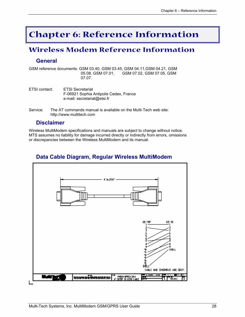
Data Cable Diagram, Regular Wireless MultiModem
Chapter 6 – Reference Information
Multi-Tech Systems, Inc. MultiModem GSM/GPRS User Guide 29
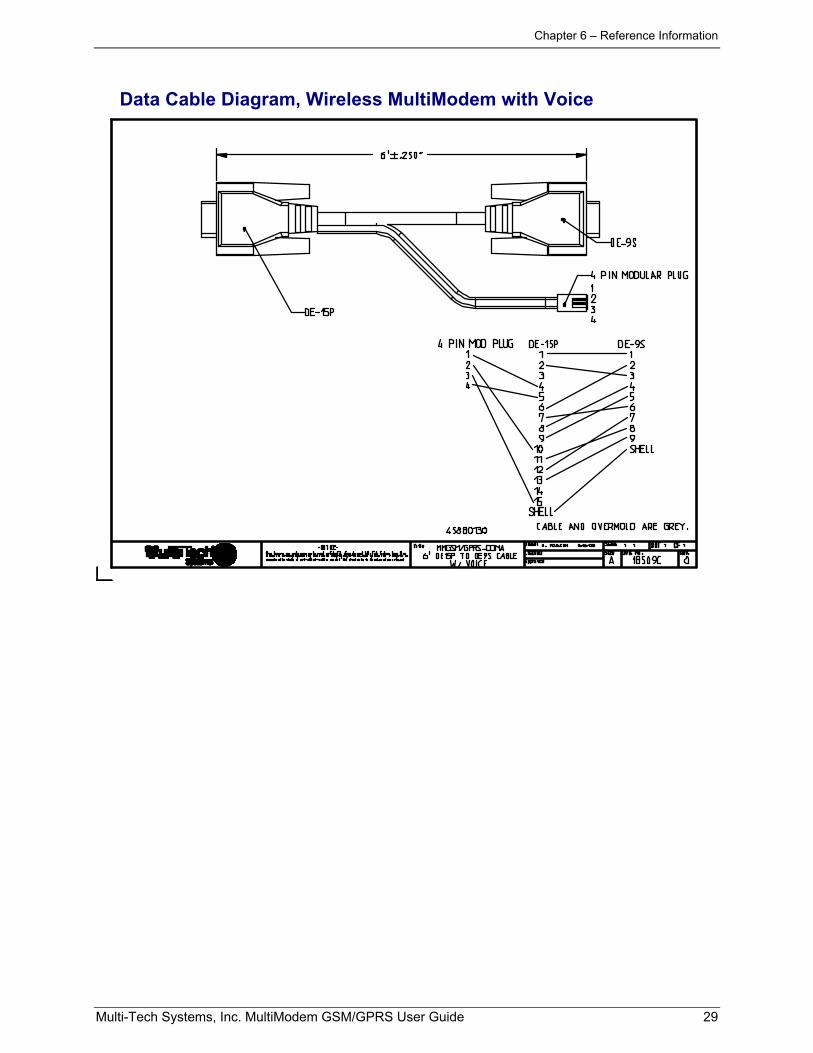
Data Cable Diagram, Wireless MultiModem with Voice