Embed Size (px)
Citation preview

Performance Evaluation 65 (2008) 262–285www.elsevier.com/locate/peva
Multipoint-to-point lightpaths in all-optical networks: Dimensioningand cost analysis
Nizar Bouabdallaha,∗, Guy Pujollec, Harry Perrosb
a INRIA, IRISA campus universitaire de beaulieu, F-35041 Rennes, Franceb Computer Science Department, NC State University, Raleigh, NC 27995-8206, United States
c LIP6, University of Paris 6, 8 rue du Capitaine Scott, F-75015 Paris, France
Received 2 June 2007; accepted 22 June 2007Available online 30 June 2007
Abstract
One of the major concerns in optical networks is the bandwidth underutilization problem. In fact, as WDM technology keepsmaturing, there is a bandwidth gap between the transmission speed of a wavelength channel (over a Gb/s) and the capacityrequirement of customers’ connections. In this regard, building cost-efficient optical networks requires an efficient traffic groomingsolution at the high speed optical access nodes. In this paper, we propose and evaluate a new concept of traffic aggregation inwavelength-division multiplexing (WDM) optical networks. Our objective is to reduce the network cost while preserving thebenefits of all-optical wavelength-routed networks. In order to assess the efficiency of our proposal, all underlying network costsare compared. These costs include that of the transceivers required at node level as well as the number of wavelengths. Our resultsshow that the proposed aggregation technique can significantly improve the network throughput while reducing its cost.c© 2007 Elsevier B.V. All rights reserved.
Keywords: Optical networking; Traffic grooming; Network dimensioning; Cost evaluation
1. Introduction
In the current nomenclature of optical networking, a network is referred to as transparent (all-optical) when itsconstituent nodes are all-optical cross connects (OXCs) where no conversion into the electrical domain is performed.Within transparent networks, lightpaths are routed from source to destination in the optical domain, opticallybypassing the intermediate nodes. The optical signal is converted into electronics only at the source and destinationnodes. In contrast, in opaque networks, lightwave channels are terminated at each node, then electronically processed,switched and reassigned to a new outgoing wavelength as needed.
In order to successfully instantiate connections, network resources (e.g., wavelengths, transceivers) have to beallocated. This issue is well known as the routing and wavelength assignment (RWA) problem. A number of RWAstudies have been conducted in the optical networking domain [1–3]. But, most previous studies assumed that aconnection requests the entire bandwidth capacity of a lightpath channel. In this study, we consider the case wherea connection can request either the whole or some fraction of the lightpath capacity. This makes the problem morepractical and general.
∗ Corresponding author.E-mail addresses: [email protected] (N. Bouabdallah), [email protected] (G. Pujolle), [email protected] (H. Perros).
0166-5316/$ - see front matter c© 2007 Elsevier B.V. All rights reserved.doi:10.1016/j.peva.2007.06.021

N. Bouabdallah et al. / Performance Evaluation 65 (2008) 262–285 263
Generating connections in an all-optical wavelength-routed network involves the establishment of point-to-point(PtoP) lightpaths between every edge node pair. These lightpaths may span multiple fiber links. The all-opticalwavelength-routing approach presents two obvious advantages. The first advantage stems from the fact that the opticalbypass eliminates the need for optical–electrical–optical (OEO) conversion at intermediate nodes. As a result, thenode cost decreases significantly, since in this case the number of required expensive high-speed electronics, lasertransmitters and receivers is reduced. The second advantage is due to all-optical routing, which is transparent withregard to the bit rate and the format of the optical signal.
In spite of the aforementioned advantages, the all-optical wavelength routing approach presents two majordrawbacks. The first one is related to the large number of wavelengths required within large networks. For a fullconnectivity, a network with N edge nodes requires O(N 2) lightpaths. The second drawback is the rigid routinggranularity entailed by such an approach. This granularity is large, which can lead to bandwidth waste. Indeed, thebandwidth demand of a traffic stream can be much lower than the capacity of a lightpath. Higher throughput andlower cost can be achieved by efficiently grooming low-speed connections onto high-capacity lightpaths. Typically,by allowing traffic from different nodes to share a single lightpath, the bandwidth can be utilized more efficiently.
On the other hand, an opaque network has the advantage of being able to efficiently use the link bandwidth.Nonetheless, as nodes do not have optical pass-through, this results in a maximum transceiver cost. In the longterm, optical packet switching (OPS) appears as a promising solution. In fact, a major advantage of electronic packetswitching is its bandwidth efficiency, relying on statistical multiplexing. Currently, there is a research effort to bringpacket switching concepts into the optical domain. However, OPS is not ready yet and it is hampered by majortechnology limitations due to the issues related to the fine switching granularity adopted (optical packet) at high bitrate [4].
In view of this, OPS is a solution that may become feasible in the future. Meanwhile, the trend is to improvethe efficiency of existing mature all-optical networks. In this regard, in our work, there has been much emphasison circuit-switched all-optical networks, where the goal in this context is shifted more towards the improvement ofoptical resource usage by means of new traffic aggregation scheme, rather than towards the attempt to realize opticalpacket switching.
To achieve this, we propose a new solution, which combines the advantage of the optical bypass in transparentwavelength routed networks with statistical multiplexing gain. In this technique, a lightpath, remaining entirely inthe optical domain, is shared by the source node and all the intermediate nodes up to the destination. So, in essence,a single lightpath is used to establish a multipoint-to-point (MptoP) connection. We refer to this technique as thedistributed aggregation scheme.
In this study, we provide typical designs of networks that function according to the distributed aggregation scheme.We consider both ring and mesh topologies. Moreover, we evaluate the network cost savings enabled by the distributedaggregation concept. To achieve this, the network cost is compared with respect to PtoP all-optical and opaquenetworks. These costs include that of the transceivers and cross-connect ports required at the node level, as wellas the number of wavelengths. We note that in practice, the transceiver cost dominates the cost of wavelengths in anetwork.
The rest of the paper is organized as follows. In Section 2, we give a literature review and point out our positionrelative to previously published papers. A detailed description of our new approach is outlined in Section 3 along withthe MAC (Medium Access Control) protocol required to avoid collisions on the shared MptoP lightpaths. Moreover,the general problem statement is presented in Section 4. In Section 5, we investigate the network architecture neededto support the traffic aggregation scheme within the optical ring topology. The network cost is then evaluated by meansof a mathematical model and compared to PtoP all-optical and opaque networks. In Section 6, we extend the studyto the regular meshed WDM networks case. Then, in Section 7, a simple provisioning algorithm, i.e., a heuristic isproposed to handle the case of arbitrary mesh topologies. In Section 8, the comparison between distributed aggregationand the existing strategies is tackled from a different perspective. We compare the blocking probability of dynamicallyarriving connection requests under all underlying strategies. Finally, some conclusions are drawn in Section 9.
2. Related work
As explained before, both opaque and PtoP all-optical networks are no longer consistent with the packet switchingphilosophy of the internet. In this context, two major enabling factors have been identified as crucial for the evolution

264 N. Bouabdallah et al. / Performance Evaluation 65 (2008) 262–285
process of the next-generation network architecture: packet switching and optical transparency. The trend is thereforetowards switching packets directly in the optical domain, as this can take advantage of both packet flexibility andoptical transparency.
In this regard, a lot of research is currently focusing on how to implement packet switching in the optical domain.However, OPS is hampered by major technology bottlenecks, such as the lack of optical processing logic, opticalmemories, and cost-effective fast switching and synchronization technologies. One way to by-pass some of thesetechnological problems is the use of optical burst switching (OBS) [5].
OBS avoids the very short switching time required by OPS. A burst is an aggregation of many packets with the sameegress node, and the same class of service. Using large bursts of data, the processing on the network can be reducedcompared to OPS. However, in OBS, there is no guarantee that a burst will be successfully transmitted without beingdropped by intermediate nodes due to contention of bursts going to the same outgoing port. Depending upon thenature of the transmitted data, a dropped burst may have to be retransmitted, which of course decreases the network’sthroughput.
OPS, and in particular OBS, is a solution that may become feasible in the future. Meanwhile, the trend is toimprove the efficiency of existing mature all-optical networks. In this regard, recently, there has been much emphasison circuit-switched all-optical networks, where the goal in this context is shifted more towards the improvementof optical resource usage by means of new traffic aggregation schemes, rather than towards the attempt to realizeoptical packet switching. Two promising solutions have been identified in the literature to reconcile betweenthe optical transparency and sub-wavelength grooming concepts: multi-hop (MH) networks and super-lightpathnetworks.
The key idea behind MH networks is to allow electronic processing at some intermediate nodes of the all-opticalcircuit-switched network in order to increase its grooming capacity [6]. Accordingly, a packet may undergo electronicprocessing at some intermediate nodes before reaching its final destination. Hence, lightpaths can be seen as chainsof physical channels through which packets are moved from one router to another towards their destinations. Atintermediate nodes, the transit lightpaths are switched transparently through an OXC that does not process transitdata. Instead, incoming lightpaths destined to the current node are terminated and converted to the electronic domain,so that packets can be extracted, processed, and possibly retransmitted on outgoing lightpaths, if the current node isnot the final destination of the data.
The cost introduced by this electronic processing operation at the intermediate nodes is significant. However, itenables a better use of the network resources and it reduces the total network cost compared to the PtoP all-opticalcircuit-switched networks [6]. The main challenge with MH networks is to identify the optimal logical topology thatminimizes the total network cost, while accommodating all the traffic requests. It has been demonstrated that theidentification of the optimal logical topology is computationally intractable for large size networks [7]. In view ofthis, several heuristic approaches were proposed in the literature [6].
The second promising solution to achieve both the optical transparency and sub-wavelength grooming is the super-lightpath concept [8]. This approach increases the grooming capacity of a regular PtoP all-optical circuit-switchednetwork, as they transform the concept of the lightpath from a PtoP pipe to a point-to-multipoint (PtoMp) pipe. Inother words, the source node of a super-lightpath does not limit its transmission to the end node of that lightpath;instead, it can transmit its traffic to all the intermediate nodes along the route. This allows the super-lightpath to carrymultiple connections, resulting in better wavelength utilization.
The super-lightpath technique uses a simple optical time division multiplexing (OTDM) method, which permitssplitting the bandwidth of a wavelength among several traffic flows. Accordingly, each bit in a given position of thefixed-size TDM frame, called a bit slot, identifies a particular sub-channel. Using a bit interleaver, the transmittermultiplexes sub-channels into the frame, and transmits the resulting stream into one lightpath. With regard toreception, each intermediate node splits the transit signal, synchronizes its receiver to a particular bit slot, and onlyreceives data in that particular sub-channel.
The super-lightpath technique presents many advantages. First, it reduces the number of transmitters per node sincethe same transmitter will be used to send data to more than one receiver. Moreover, it improves the lightpath utilization.The main concern with this PtoMp method is related to the limited length of the super-lightpath. Specifically, asignificant portion of the passing-through optical signal is tapped at each receiving intermediate node, and therefore,due to power limitations the number of traversed nodes is limited.

N. Bouabdallah et al. / Performance Evaluation 65 (2008) 262–285 265
Fig. 1. A simple demonstration network. (a) All-optical wavelength routed network. The connection request (1, 2) is rejected. (b) Distributedaggregation scheme. All connection requests are satisfied.
3. Distributed aggregation scheme
The key idea underlying our proposed scheme is to allow sharing of a lightpath among several access nodes. Insteadof limiting the access to the lightpath capacity at the ingress point, each node along the path can fill the lightpath onthe fly according to its availability. In this case, a lightpath can be shared by multiple connections traveling towardsa common destination (i.e., MptoP lightpaths). Wavelength routing is performed in a similar way as in all-opticalnetworks, i.e. signals remain in the optical domain from end to end and are optically switched by intermediate nodes.Since the lightpath remains transparent at intermediate nodes, a MAC (medium access control) protocol is required toavoid collision between transient optical packets and local ones injected into the lightpath. We have already proposeda simple MAC protocol based on void/null detection in [9]. This mechanism, which will be described next, guaranteescollision free packet insertion on the transient wavelength at the add port level of an intermediate node. Briefly, thisis done as follows. Each station monitors the transmission of the optical packets on the pass-through lightpath, andwhen it detects a big-enough gap between two successive packets, it transmits a packet from its own buffer.
3.1. The distributed aggregation scheme: An example
To illustrate the distributed aggregation mechanism, we consider the simple three-node network example shownin Fig. 1. We assume that each fiber has one wavelength and each node is equipped with a fixed transmitter and afixed receiver. Two connection requests are to be served: (0, 2) with a bandwidth requirement equal to half of thewavelength capacity; and (1, 2) with a bandwidth requirement equal to quarter of the wavelength capacity.
In the PtoP all-optical network case (Fig. 1(a)), only the connection (0, 2) will be served. The connection betweennode pair (1, 2) will be rejected even if the wavelength between these two nodes is not being fully used. Hence, anextra wavelength between pair nodes (1, 2) and a new receiver at node 2 would be required in order to satisfy all theconnection requests.
However, using the distributed aggregation scheme (Fig. 1(b)), the traffic demand could be satisfied by establishingone lightpath from node 0 to node 2. In this case, both connections will share the same lightpath. Indeed, thesecond connection (1, 2) would be carried using the spare capacity of the existing lightpath. Note that the lightpath0 → 1 → 2 is still routed optically through node 1, thus preserving the benefit of optical bypass.
The merit of distributed aggregation is that multiple connections with fractional demands can be multiplexed ontothe same lightpath. As a result, the wasted bandwidth problem associated with pure wavelength routed networksis alleviated. In addition, due to the sharing of lightpaths, the number of admissible connections in the network isincreased. Furthermore, the destination node handles fewer lightpaths as connections from different nodes to the samedestination are aggregated onto the same lightpath. In view of this, fewer physical components, such as wavelengthsand transceivers, are used, resulting in savings on equipment. Moreover, in order to provide connections between allaccess node pairs using MptoP lightpaths, a total number of O(N ) lightpaths is required since only one lightpath perindividual egress node could be sufficient. Thus, we alleviate the scalability issue encountered in classical all-opticalwavelength routed networks.
3.2. The MAC protocol
Let us consider J nodes placed along a unidirectional lightpath. Buffered packets at each node level are transmittedonto the lightpath towards the node where the lightpath is terminated. These packets travel along the lightpath withoutany electro-optic conversion at intermediate nodes.

266 N. Bouabdallah et al. / Performance Evaluation 65 (2008) 262–285
Fig. 2. Schema of the CSMA/CA based MAC.
The main issue with this scheme is collision-free packet insertion on a shared MptoP lightpath. Neither activeoptical devices nor electronic conversions are employed to handle the packet insertion. Instead, traffic controlmechanisms are used at the electronic edge of the access nodes to avoid collisions with transit traffic.
We believe that asynchronous transmission allows for a better use of resources as opposed to synchronoustransmission. Asynchronous transmission fits better the traffic flowing in high-speed networks, which is typicallybursty. The authors of [10] showed the limitations of the TDMA approach due to the lack of statistical multiplexing.Hence, we focus in this paper on a contention-based media access protocol rather than on a time-sharing solution.
In a fixed-slotted system with fixed-size packets, void (i.e. slot) filling can be carried out immediately upon itsdetection, since the void duration is a multiple of the fixed-size packet duration. The detected void is thereforeguaranteed to provide a minimum duration of one packet length. However, in non-slotted systems with variable packetlength and arbitrary void duration, a collision may occur if a packet is immediately transmitted upon the detection ofthe beginning of a void.
To meet these requirements, each node along the shared lightpath must retain the upstream traffic flow within theoptical layer while monitoring the medium activity. Specifically, as shown in Fig. 2, each node first uses an opticalsplitter to separate the incoming signal into two identical parts: the main transit signal and its copy used for controlpurposes. With regard to the control part, as in [11], low bit rate photodiodes (ph)—typically 155 MHz—are used tomonitor the activity of the transit lightpath. Once a free state of the medium is detected, the MAC unit measures thesize of the progressing void.
To do so, a fiber delay line (FDL) is introduced on the transit path to delay the upstream flow by one maximumframe duration augmented by the MAC processing time. The length of the FDL is slightly larger than the maximumtransmission unit (MTU) size allowed within the network, in order to provide the MAC unit with sufficient time tolisten and to measure the medium occupancy. The node will begin injecting a packet to fill the void only if the nullperiod is large enough (i.e. at least equal to the size of the packet to be inserted). Undelivered data will remain bufferedin the electronic memory of the node until a sufficient void space is detected. This way, collision free packet insertionon the pass-through lightpath from the add port is ensured.
It is easy to see that such an access scheme relies only on passive components (couplers, FDL, ph) with relativelylow cost. The cost introduced by the MAC unit is negligible compared to the transceiver cost. However, with this basicpacket insertion mechanism, head of the line blocking and fairness issues could arise. Indeed, such a transmissionscheme introduces an unfair advantage to those nodes that are closer to the source node. The fairness of this schemewas examined in [12], where we proposed an additional protocol, called Traffic Control Architecture using RemoteDescriptors (TCARD), that eliminates unfairness among optical nodes. In TCARD, each transmitting station isequipped with anti-tokens that prevent the station from transmitting a packet during a gap in the optical packet stream.These anti-tokens permit some of the gaps to go by unused, and therefore, they can be used by other downstreamstations. The rate of generation of the anti-tokens at a station is set equal to the rate of the aggregate downstreamtransmission.
N. Bouabdallah et al. / Performance Evaluation 65 (2008) 262–285 267
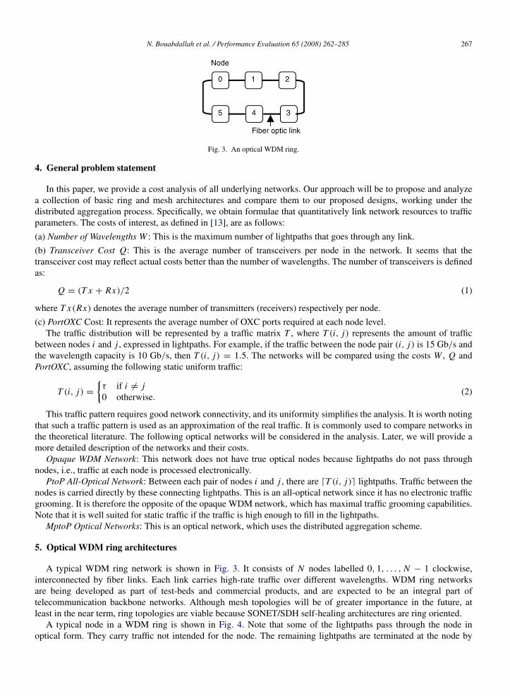
Fig. 3. An optical WDM ring.
4. General problem statement
In this paper, we provide a cost analysis of all underlying networks. Our approach will be to propose and analyzea collection of basic ring and mesh architectures and compare them to our proposed designs, working under thedistributed aggregation process. Specifically, we obtain formulae that quantitatively link network resources to trafficparameters. The costs of interest, as defined in [13], are as follows:
(a) Number of Wavelengths W : This is the maximum number of lightpaths that goes through any link.
(b) Transceiver Cost Q: This is the average number of transceivers per node in the network. It seems that thetransceiver cost may reflect actual costs better than the number of wavelengths. The number of transceivers is definedas:
Q = (T x + Rx)/2 (1)
where T x(Rx) denotes the average number of transmitters (receivers) respectively per node.
(c) PortOXC Cost: It represents the average number of OXC ports required at each node level.The traffic distribution will be represented by a traffic matrix T , where T (i, j) represents the amount of traffic
between nodes i and j , expressed in lightpaths. For example, if the traffic between the node pair (i, j) is 15 Gb/s andthe wavelength capacity is 10 Gb/s, then T (i, j) = 1.5. The networks will be compared using the costs W , Q andPortOXC, assuming the following static uniform traffic:
T (i, j) =
{τ if i 6= j0 otherwise.
(2)
This traffic pattern requires good network connectivity, and its uniformity simplifies the analysis. It is worth notingthat such a traffic pattern is used as an approximation of the real traffic. It is commonly used to compare networks inthe theoretical literature. The following optical networks will be considered in the analysis. Later, we will provide amore detailed description of the networks and their costs.
Opaque WDM Network: This network does not have true optical nodes because lightpaths do not pass throughnodes, i.e., traffic at each node is processed electronically.
PtoP All-Optical Network: Between each pair of nodes i and j , there are dT (i, j)e lightpaths. Traffic between thenodes is carried directly by these connecting lightpaths. This is an all-optical network since it has no electronic trafficgrooming. It is therefore the opposite of the opaque WDM network, which has maximal traffic grooming capabilities.Note that it is well suited for static traffic if the traffic is high enough to fill in the lightpaths.
MptoP Optical Networks: This is an optical network, which uses the distributed aggregation scheme.
5. Optical WDM ring architectures
A typical WDM ring network is shown in Fig. 3. It consists of N nodes labelled 0, 1, . . . , N − 1 clockwise,interconnected by fiber links. Each link carries high-rate traffic over different wavelengths. WDM ring networksare being developed as part of test-beds and commercial products, and are expected to be an integral part oftelecommunication backbone networks. Although mesh topologies will be of greater importance in the future, atleast in the near term, ring topologies are viable because SONET/SDH self-healing architectures are ring oriented.
A typical node in a WDM ring is shown in Fig. 4. Note that some of the lightpaths pass through the node inoptical form. They carry traffic not intended for the node. The remaining lightpaths are terminated at the node by

268 N. Bouabdallah et al. / Performance Evaluation 65 (2008) 262–285
Fig. 4. A WDM ring node.
Fig. 5. An opaque WDM ring with three wavelengths.
transceivers, and their traffic is converted into electronic form, and processed electronically. The electronic processing(and switching) includes systems such as SONET/SDH ADMs, IP routers, and digital cross-connect systems (DCSs)that cross-connect traffic streams. To simplify the presentation, we shall observe IP router systems at a later stage, butthe very same discussion holds for the other type of electrical nodes. In Fig. 4, the IP router is shown representing allthe electronic processing, and the transceivers are located at the interface of the IP router and lightpaths.
5.1. The opaque WDM ring
A special case of an optical ring network is the opaque WDM ring network shown in Fig. 5. Here, each link in thenetwork has one-hop lightpaths on each of its wavelengths. The network is called an opaque ring because lightpathsare established only between neighboring nodes. Each node has a single IP router that routes traffic from all thelightpaths.
The opaque ring has the advantage of being able to efficiently use the link bandwidth for time-varying traffic. Itsdisadvantage is that its nodes do not have optical pass-through, resulting in maximum transceiver cost. For instance, ina typical carrier network, each link may have 16 wavelengths, each carrying 10 Gb/s traffic data. Suppose a ring nodeneeds to terminate only one lightpath worth of traffic. In this case, the node would ideally pass through the remaining15 lightpaths in optical form without processing them. On the other hand, an opaque ring would require the trafficfrom all 16 wavelengths to be received, possibly switched through an electronic IP router, and retransmitted. Thisoperation can have a great impact on the network cost.
Assume the opaque ring network and static uniform traffic as before. We assume that all traffic is routed along theshortest path in the ring. Then, the average number of hops, H , needed to route traffic from its source to its destination

N. Bouabdallah et al. / Performance Evaluation 65 (2008) 262–285 269
Fig. 6. Setting up two lightpaths between the first two nodes.
is:
H =
N + 1
4N odd,
N + 14
+1
4(N − 1)N even.
(3)
Therefore, the amount of traffic going through a link is:
L =H × Total trafficNumber of links
=
H ×∑i
∑j
T (i, j)
N=
N 2
− 14
· τ N odd,
N 2
4· τ N even.
In this case, as the lightpaths are unidirectional, the number of wavelengths required by each link is:
W =
2⌈
N 2− 1
8· τ
⌉N odd,
2⌈
N 2
8· τ
⌉N even.
(4)
Also recall that the number of transceivers per node is:
Q = W = T x = Rx . (5)
5.2. The PtoP all-optical ring
In this network dT (i, j)e lightpaths have to be set up between each source and destination nodes. This type ofnetwork has been considered in [13], but for the case of full duplex lightpaths. Let us consider the static uniformmatrix with τ = 1 and unidirectional (half duplex) lightpaths as before. Now we need to set one lightpath betweeneach pair of nodes. The wavelength assignment will be done on a recursive basis as shown below. Let N be even.
(1) Start with two nodes on the ring (see Fig. 6). The two lightpaths (one for each direction) that need be set upwill require only one wavelength since the lightpaths can use disjoint routes.
(2) (Recursive step.) Let k denote the number of nodes currently in the ring. While k ≤ N −2, add two more nodesto the ring so that they are diametrically opposite to each other, i.e., separated by the maximum number of hops (seeFig. 7). The two new nodes divide the ring in half, where each half has k/2 old nodes. In one half, each old node setsup two lightpaths to each new node. Therefore, each old node needs four lightpaths to connect to the new nodes. Thisrequires, however, only two wavelengths per old node since each old node can fit its four lightpaths using the samepair of wavelengths (as the lightpaths use disjoint routes). Thus, a total of k new wavelengths are required. The oldnodes in the other half of the ring can do the same thing and use the same wavelengths. Finally, the two new nodesrequire an additional wavelength to be connected. Thus, we need to add a total of k + 1 new wavelengths. So thenumber of wavelengths needed to do the assignment is:
W = 1 + 3 + 5 + · · · + N − 1 =N 2
4.

270 N. Bouabdallah et al. / Performance Evaluation 65 (2008) 262–285
Fig. 7. Setting up lightpaths for two new nodes.
Fig. 8. Overview of MptoP ring network and node architecture.
For arbitrary τ the wavelength assignment can be done with
W = dτeN 2
4(6)
wavelengths, where N is even.When N is odd, we start the procedure above with three nodes and add two nodes each time. The number of
wavelengths in this case can be calculated to be:
W = dτeN 2
− 14
. (7)
In addition, the number of transceivers required per node is:
Q = dτe(N − 1). (8)
5.3. The MptoP optical ring
Here, we describe our proposed architecture enabling the distributed aggregation scheme. This network has a node,designated as the hub (denoted by node 0), which has lightpaths directly connecting it to all the other nodes (Fig. 8).A connection request between two ring nodes has to traverse two lightpaths before it reaches its destination. The hubnode connects the ring to the backbone network.
The network can be described as a unidirectional fiber split into downstream and upstream channels spectrallydisjointed (i.e. on different wavelengths). The downstream bus, initiated at the hub node, is a shared medium for

N. Bouabdallah et al. / Performance Evaluation 65 (2008) 262–285 271
reading purposes, while the upstream bus, initiated at the ring nodes, is a multiple access-writing medium. In thedownstream direction, the ring is a point-to-multipoint network, and in the upstream direction it is a multipoint-to-point network that uses the distributed aggregation scheme.
Let us consider N nodes placed in the unidirectional ring, as shown in Fig. 8. Each node serves one or more accessnetworks. Typically, most of the traffic from the access networks has its destination out of the ring network. Such atraffic, which is carried to the core via the hub node, is collectively called hubbed traffic.
With regard to the direction from the access networks to the feeder ring, the ring node plays the role of aconcentrator. Buffered packets are transmitted on the upstream bus towards the hub without any electro-opticconversion at intermediate nodes. The intermediate nodes can use pass-through lightpaths to inject their local traffictowards the hub. Specifically, a lightpath remaining entirely in the optical domain is shared by a source node and allintermediate nodes up to the hub.
The hub terminates the upstream wavelengths and electronically processes the packets. According to its destination,a packet is forwarded either into the backbone network or through the downstream bus to reach the ring nodes to whichit is destined. In the downstream direction, the hub maintains lightpaths to various ring nodes. Each lightpath can beshared in reception by several ring nodes. To do so, each ring node copies the downstream signal, originating from thehub, using a splitter, from which it recovers the transmitted packets. Once split, the main signal is no longer processedat the node level and it continues its path towards the other ring nodes sharing the lightpath. Each ring node terminatesthe copied lightpath, electronically processes the data packets and delivers them to users.
As stated before, the main issue with this scheme is the collision-free packet insertion on the shared upstream bus,which can be solved using the MAC protocol described above.
This architecture fits the hubbed traffic networks, which are often observed in access rings. The spectral separationallows the use of a simple passive structure for the optical part of ring nodes. In this context, this architecture inheritsthe advantages of PON technology [14]. Moreover, we preserve the optical transparency property. Thus, ring nodeswill need transceivers for their local traffic only. In addition, as described above it provides a fraction of the wavelengthcapacity to each ring node, a single wavelength for all upstream nodes, and a single head-end receiver at the hub node.Hence, the hub transceiver needs are also reduced.
As stated before, any intermediate node i(i = 2, . . . , N − 1) can use the traversing lightpaths to inject its localtraffic intended to the hub node. If sufficient capacity exists, the ring node i traffic would be carried by the sparecapacity of the pass-through lightpaths. Otherwise, the node i has to create new lightpaths to handle the remaininglocal traffic destined to the hub. Here, we suppose that the traffic injected by the different ring nodes is perfectlymultiplexed in the upstream wavelengths. Considering the static uniform traffic with parameter τ , then the number ofupstream wavelengths is:
Wup = d(N − 1)2τe. (9)
Likewise, the number of downstream wavelengths is:
Wdown = d(N − 1)2τe. (10)
Thus, the total number of required wavelengths is:
W = Wup + Wdown. (11)
Let us consider ring node i (i = 1 . . . N − 1). Node i has to transmit Λ = (N − 1)τ lightpaths of traffic to the hubnode. The available bandwidth seen by node i on the traversing lightpaths coming from upstream nodes (i.e. nodes1, . . . , i − 1) is:
Bw(i) = d(i − 1)Λe − (i − 1)Λ.
The required number of transmitters at node i is then:
T x(i) = dΛ − Bw(i)e + dBw(i)e.

272 N. Bouabdallah et al. / Performance Evaluation 65 (2008) 262–285
Fig. 9. The number of required wavelengths in the WDM ring networks.
It can be demonstrated that the total number of transmitters at all ring nodes (excluding the hub node) is provided bythe expression:
N−1∑i=1
T x(i) = N +W
2− 2 −
N−2∑i=1
1|diΛe − iΛ = 0.
The number of required transmitters and receivers at the hub node can be given by:
T x[0] = Rx[0] = Wup = Wdown.
Hence, the average number of transmitters per node is:
T x =1N
N−1∑i=0
T x(i) = 1 +
W − 2 −
N−2∑i=1
1| diΛe − iΛ = 0
N. (12)
Similarly, we obtain the number of receivers per node
Rx = T x = Q. (13)
5.4. Comparison
In this section, we compare the different WDM ring networks. Based upon the calculated key costs, we draw thefollowing conclusions:
– If wavelengths are plentiful, then the MptoP ring is a good choice. It shows the lowest transceiver cost when thetraffic request between every pair of nodes is a fraction of the lightpath capacity. The PtoP all-optical ring is also areasonable choice only if the traffic between each pair of nodes is high enough to fill in the entire lightpath capacity.In other words, the PtoP ring is cost effective when the value of τ is about dτe. On the other hand, the opaque ringnearly always leads to the highest transceiver cost since its nodes do not have optical pass-through. Even so, we noticethat the opaque approach is cost effective when τ is very small compared to the wavelength capacity.
– If wavelengths are precious, then the opaque and PtoP rings are logical choices for WDM ring networks sincethey use minimal wavelengths. The opaque ring always provides the most efficient use of wavelength. We point outthat the MptoP approach is more suitable for hubbed traffic. In this regard, the uniform traffic matrix can be seen as aworst case for MptoP rings. In addition, we recall that in our model the cost of transceivers is a dominant issue.
Figs. 9 and 10 show W and Q values, respectively for the case N = 8. In the figures, τ ranges from 0 to 1.Fig. 9 shows that opaque and PtoP rings have the optimal W . Fig. 10 shows that minimum Q is attained by different

N. Bouabdallah et al. / Performance Evaluation 65 (2008) 262–285 273
Fig. 10. The transceiver requirement per node in the WDM ring networks.
Fig. 11. Optical node architecture.
networks for different values of τ . For τ > 1/2, the PtoP ring has the smallest Q. For τ ≤ 1/2, the MptoP ring hasthe smallest Q. Thus, for a small value of τ (where traffic grooming is more interesting), the MptoP ring attains theminimum or nearly the minimum for both Q and W . If wavelengths are abundant, then MptoP and PtoP rings lead tothe smallest transceiver cost. Note that this example shows that different architectures provide better transceiver costsover different values of τ .
6. WDM mesh network architectures
This section can be seen as an extension of the previous study to the case of mesh networks. To carry connectionrequests in such a WDM network, lightpath connections may be established between pairs of nodes. Two importantfunctionalities must be supported by the WDM network nodes: one is wavelength routing and the other is trafficgrooming. Fig. 11 depicts a sample node architecture that can be employed in a WDM optical network. The nodearchitecture comprises two components: the wavelength selective device and the access station (e.g. IP router). Whilethe wavelength selective device performs wavelength routing, the access station performs local traffic adding/droppingand low-speed traffic-aggregation functionalities.

274 N. Bouabdallah et al. / Performance Evaluation 65 (2008) 262–285
Fig. 12. 4 × 4 MSN.
Bear in mind that we aim at dimensioning the optical WDM mesh network so as to serve all traffic requests betweenany pair of optical nodes. This is achieved by evaluating the OXC and IP router dimensions as well as the numberof wavelengths. Each port of the electrical IP router is connected to the OXC port via an internal wavelength. Alltraffic between nodes is carried over the WDM links. A lightpath is established between nodes by setting up the OXCsalong the route between nodes. Each lightpath needs a dedicated OXC port when traversing an intermediate node. Inaddition, a transceiver pair is required at the ingress and egress nodes of the lightpath. Moreover, in the distributedaggregation case, each intermediate node along the path using a pass-through lightpath to transmit its traffic also needsa transmitter. In fact, the access station of a node can be either the origin of a lightpath or an intermediate node usingan already established lightpath. In the latter case, the injected traffic by an intermediate node should have the samedestination as that of the traversing lightpath.
Mesh topologies can be broadly classified into two categories: arbitrary and regular. Nodal connectivity patternsin regular topologies are very systematic and well defined, which simplifies routing and management operations aswell as theoretical network studies. Regular topologies are widely used to compare different network designs in theliterature. Suitable regular topologies include the Shufflenet [15], the de Bruijn Graph [16], the Hypercube [17], theManhattan Street Network (MSN) [18], and the Kautz Graph [19]. Each of these architectures bases its merits onoptical infrastructure. In this paper, the MSN is selected as the exemplar architecture. Nevertheless, the techniquesadopted are sufficiently general and similar results can be obtained for the other architectures. MSN is chosen becauseit is one of the most popular architectures.
The MSN, Fig. 12, is a member of a class of multiply connected, regular, mesh-configured networks. The proposalname MSN considered unidirectional links, so that two links arrive at and depart from each node. It can be observedthat the topology is made of a number of horizontal (rows) and vertical (columns) rings. Logically, the links form agrid on the surface of a torus, with links in adjacent rows or columns traveling in opposite directions.
We assume the following network characteristics:– The meshed topology is formed by unidirectional horizontal and vertical rings.– A node always transmits data on the horizontal ring if the destination node does not belong to the same vertical
ring.– A shortest path routing algorithm is used to route the lightpaths over the physical topology. Based on the
aforementioned conditions, the route between each node pair is thus unique.– Each node contains a selective wavelength device, i.e. an OXC, that routes and manipulates the lightpaths as
desired.Consider an N × N (square) MSN topology, and identify nodes with a pair of integers specifying their position
in the grid, measured by a row and a column number. Node (i, j) (row i , column j , with i, j = 0, . . . , N − 1)always transmits on the horizontal ring i if the destination node does not belong to the same vertical ring j . Node(i, j) always receives data from the vertical ring j if the source node does not belong to the same horizontal ring i .Note that at every node (i, j), the optical signal arriving on the horizontal ring i is demultiplexed in order to separatelightpaths. Some of the optical channels are switched to the vertical ring j . The remaining lightpaths instead continuetheir journey along the horizontal ring i .
Assuming all the traffic is routed along the shortest path in the MSN network, the average number of hops Hneeded to route traffic from its source to its destination is:
H =N 2
N + 1. (14)

N. Bouabdallah et al. / Performance Evaluation 65 (2008) 262–285 275
The number of physical hops traversed by a lightpath is important for several reasons: it affects the number ofrequired wavelengths and impacts on the dimensioning of the selective wavelength devices. Recall that each lightpathneeds a dedicated OXC port when traversing an intermediate node along the path (including the source and destinationnodes). Because of the cyclic structure of the MSN and uniform static matrix, any node can be considered to be in thecenter of the network and needs the same number of OXC ports. The number of OXC ports is simply:
PortOXC = pass through lightpaths + received lightpaths + emitted lightpaths.
Note that this parameter is not considered in the opaque case since there is no wavelength-switching device in sucha network. In the remainder of this paper, we will consider an arbitrary node (i, j) since all the network nodes exhibitthe same behaviour.
6.1. Opaque mesh networks
As explained before, each link in the network carries a one-hop lightpath on each of its wavelengths. The lightpathsare established only between neighboring nodes. Considering the opaque MSN and static uniform traffic as before,each link in the network carry the same amount of traffic. Therefore, the amount of traffic going through each link is:
L =H × Total trafficNumber of links
=
H ×∑i
∑j
T (i, j)
2N 2 =N 2(N − 1)τ
2.
Hence, the number of wavelengths traversing each link is:
W =
⌈N 2(N − 1)τ
2
⌉. (15)
As two links arrive at and depart from each node, the number of transmitters and receivers per node is equal to:
Q = T x = Rx = 2W = 2⌈
N 2(N − 1)τ
2
⌉. (16)
6.2. PtoP all-optical mesh networks
In this network, dτe lightpaths have to be set up between each source and destination nodes. Due to the symmetricalproperty of the unidirectional MSN conjugated with the uniform static matrix and the deterministic routing, eachlink of the network is traversed by the same number of lightpaths. So the number of wavelengths needed to do theassignment is:
W =H × Total number of lightpaths
Number of links=
H ×∑i
∑jdT (i, j)e
2N 2 =N 2(N − 1)
2dτe. (17)
On the other hand, the number of transmitters and receivers required per node is given by:
Q = T x = Rx = (N 2− 1)dτe. (18)
Since, two links arrive at and depart from each node, the number of pass-through lightpaths traversing each node isequal to 2W − Rx . The number of OXC ports per node is then:
PortOXC = 2W + T x = [N 2(N − 1) + (N 2− 1)]dτe. (19)
6.3. MptoP optical mesh networks
In this network, a lightpath can be shared by multiple connections traveling towards a common destination. So,instead of limiting access to lightpath capacity at the ingress point, each node along the path can instantaneously fill

276 N. Bouabdallah et al. / Performance Evaluation 65 (2008) 262–285
in the optical resource according to its availability. Remember that node (i, j) always transmits on the horizontal ringi , and receives on the vertical ring j . Besides, we use the shortest path routing strategy. Thus, the route between eachnode pair is unique.
The node (i, j) emits traffic towards N 2− 1 nodes gathered on N vertical rings (including the vertical ring that
node (i, j) belongs to, i.e. column j). As stated earlier, a node (i, j) can use a pass-through lightpath, coming from thenodes of the same horizontal ring i , to inject its local traffic intended to the egress node of that lightpath. If sufficientcapacity exists, the node (i, j) traffic would be carried by the spare capacity of the pass-through lightpath. Otherwise,the node (i, j) has to create new lightpaths to handle the remaining local traffic going to the same destination. Thenumber of required transmitters at node (i, j) can be calculated recursively as follows:
(1) First, let us consider the vertical ring VN−1 situated at N − 1 hops from node (i, j). The node (i, j) is theinitiator of the lightpaths going towards the N nodes of VN−1. So, node (i, j) needs
T x(N − 1) = Ndτe
transmitters to forward its traffic to the N nodes of VN−1.(2) Let us consider now, the vertical ring VN−2. Node (i, ( j + N − 1) mod N ) is the initiator of the N lightpaths
to VN−2 since it is the farthest node to the column VN−2. Node (i, j) tries first to use the available bandwidth on eachof the N transit lightpaths. If the spare capacity on each lightpath is insufficient (i.e. smaller than τ ), node (i, j) hasto create new lightpaths to handle the remaining traffic. Thus, the number of required transmitters can be given by:
T x(N − 2) = (dτ − (dτe − τ)e + 1|{dτe − τ > 0})N .
(3) Let us consider the general case, the vertical ring Vk (k = 1 . . . N − 1) (i.e. the vertical ring situated at k hopsfrom node (i, j)). Node (i, ( j + k + 1) mod N ) is the initiator of the N lightpaths to Vk since it is the farthest node tothe column Vk . The number of required transmitters at node (i, j) is:
T x(k) = (dτ − (d(N − k − 1)τe − (N − k − 1)τ )e + 1|{d(N − k − 1)τe − (N − k − 1)τ > 0})N .
(4) Let us consider the particular case of the vertical ring V0 that belongs to the node (i, j). Node (i, ( j +1) mod N )
is the initiator of the N − 1 lightpaths to V0 (excluding node (i, j)). Similarly, the number of needed transmitters canbe derived as follows:
T x(0) = (dτ − (d(N − 1)τe − (N − 1)τ )e + 1|{d(N − 1)τe − (N − 1)τ > 0})(N − 1)
Finally, the number of transmitters needed at node (i, j) can be written as:
T x =
N−1∑k=0
T x(k) =
(N
N−2∑k=0
(dτ − (dkτe − kτ)e + 1|{dkτe − kτ > 0})
)+ (dτ − (d(N − 1)τe − (N − 1)τ )e + 1|{d(N − 1)τe − (N − 1)τ > 0})(N − 1). (20)
On the other hand, node (i, j) receives traffic, on the vertical ring j , coming from N horizontal rings (includingthe horizontal ring it belongs). The number of required receivers at each node can be easily derived
Rx = (N − 1)dNτe + d(N − 1)τe. (21)
Hence, the number of transceivers per node is:
Q = (T x + Rx)/2. (22)
Due to the symmetrical property of the unidirectional MSN and the uniform static matrix adopted, all theunidirectional links of the horizontal rings are traversed by the same number of lightpaths. In the same way, all theunidirectional links of the vertical rings require the same number of wavelengths in order to carry all the connectionrequests. Let us consider the unidirectional horizontal link L i binding node (i, j) to node (i, ( j + 1) mod N ). Thenumber of wavelengths traversing L i can be determined recursively as follows:
(1) First, let us consider the vertical ring VN−1 situated at N − 1 hops from node (i, j). The node (i, j) is theinitiator of the lightpaths going towards the N nodes of VN−1. So, node (i, j) needs
W (N − 1) = Ndτe

N. Bouabdallah et al. / Performance Evaluation 65 (2008) 262–285 277
wavelengths, traversing L i , to forward its traffic to all the nodes of VN−1. The remaining nodes of the horizontal ringi will not use the link L i in order to reach the nodes of VN−1.
(2) Let us consider now, the vertical ring Vk (k = 1 . . . N − 1). N − k nodes will use the link L i to forward theirtraffic to Vk . So, the number of additional wavelengths traversing L i to reach the nodes of Vk is:
W (k) = Nd(N − k)τe.
Finally, the number of required wavelengths at each unidirectional horizontal link is given by:
Whor = NN−1∑i=1
diτe. (23)
On the other hand, each vertical ring j behaves as a PtoP all-optical unidirectional ring where dNτe lightpaths arerequired between each pair of nodes of the ring. The average hop number per lightpath in a unidirectional ring withN nodes is h = N/2. So, the number of wavelengths on each vertical link is given by:
Wver =h × Total number of lightpaths
number of links=
N (N − 1)
2dNτe. (24)
Thus, the number of wavelengths required in the network is:
W = Max(Whor, Wver). (25)
Two links arrive at and depart from each node. So, the number of pass-through lightpaths bypassing each node isequal to Whor + Wver − Rx . In addition, the number of emitted lightpaths by each node can be given by:
Emitted lightpaths =
(N
N−2∑k=0
dτ − (dkτe − kτ)e
)+ (dτ − (d(N − 1)τe − (N − 1)τ )e)(N − 1).
The number of OXC ports per node is then:
PortOXC = Whor + Wver + emitted lightpaths. (26)
6.4. Comparison
In this section, we will compare the WDM mesh networks from the previous section. Briefly speaking, one candraw the following conclusions:
– If wavelengths are plentiful then the MptoP strategy is the best choice since it has the lowest transceiver cost. ThePtoP all-optical strategy is also a good choice only if the traffic between each pair of nodes is high enough to fill inthe entire capacity of lightpaths. On the other hand, opaque strategy always leads to the highest transceiver cost sinceits nodes do not have optical pass-through.
– If wavelengths are precious, then opaque and MptoP strategies are sensible choices for WDM mesh networkssince they use minimal wavelengths. The opaque network always provides the most efficient use of wavelengths.MptoP network requires slightly more wavelengths but it potentially reduces the transceiver cost. PtoP network is theleast effective especially when only a portion of the lightpaths capacity is used.
– The dimensioning of the selective wavelength devices (i.e. number of OXC ports) shows that the MptoP strategyallows a great savings on OXC ports over the PtoP strategy mainly when the traffic between each pair of nodes requiresa fraction of the wavelength capacity.
Figs. 13–15 show W , Q and PortOXC values, respectively for the case N = 8 (i.e. the network comprises 64nodes). In the figures τ ranges from 0 to 3. Fig. 13 shows that opaque and MptoP strategies have the optimal W .Fig. 14 shows that minimum transceivers cost is always attained by MptoP and PtoP networks. For small to moderatevalue of τ (which is where traffic grooming is more interesting), the MptoP network attains the minimum or nearly theminimum for both Q and W . In fact its improvement in Q over the opaque MSN can be significant. For example forτ = 1.5, the MptoP MSN has a Q that is 80% smaller than the one for the opaque MSN. In addition, in this case, theMptoP MSN has a W that is 30% smaller than the one for the PtoP MSN. In this regard the MptoP MSN can be seen

278 N. Bouabdallah et al. / Performance Evaluation 65 (2008) 262–285
Fig. 13. The number of required wavelengths in the MSN network.
Fig. 14. The transceiver requirement per node in the MSN network.
Fig. 15. The OXC port requirement per node in the MSN network.

N. Bouabdallah et al. / Performance Evaluation 65 (2008) 262–285 279
Fig. 16. The US optical backbone.
as a mixture of two extreme cases (PtoP and opaque networks) providing a trade-off between number of wavelengthsand transceiver cost. Later we shall focus on the comparison between MptoP and PtoP strategies.
As multiple connections traveling from different nodes to the same destination could be aggregated on the samelightpath with the MptoP approach, the destination node will receive fewer lightpaths. Consequently, the number ofrequired receivers as well as wavelengths to handle all the traffic requests is reduced as depicted in Fig. 13. In thiscase, more than 55% of receiver savings can be achieved. Moreover, the MptoP strategy provides more than 30%reduction in average wavelength requirements. Since W is reduced in MptoP networks, the number of OXC ports isalso reduced. The OXC port gain hence recorded can reach 60% as shown in Fig. 15.
In summary, MptoP MSN almost always has the smallest transceiver cost and leads to an efficient use of thewavelength resources. This architecture combines the merits of optical pass-through, leading to a great savings on thetransceiver cost, and statistical multiplexing gain allowing efficient use of the wavelengths. Note that PtoP MSN isalso effective when τ approaches dτe.
7. Heuristic approach
7.1. Heuristic
In the previous section, we used regular topologies as an illustration where it was possible to obtain explicit formulausing the analytical methodology. In [20], we used a small arbitrary connected network as an illustration where it waspossible to obtain results using the integer linear programming (ILP) methodology. Nonetheless, in order to achieve thesame study for large and arbitrary connected networks, we will use a heuristic approach. Here, we aim at dimensioningthe optical US backbone (Fig. 16), under different strategies. The network topology consists of 29 nodes and 43 links.The network planning has been achieved after the logical process shown below. The input of the analysis is:
(1) The physical network topology.(2) The traffic matrix, which is a uniform static matrix.(3) The adopted routing scheme, which is the shortest path algorithm in our case.(4) The adopted wavelength assignment approach, which is the first fit (FF) strategy in our work.The network dimensioning is achieved by evaluating the OXC and IP router dimensions by means of the heuristic
algorithm used to map the different lightpaths needed to forward all the traffic requests within the network. We omit,here, the number of wavelengths since we consider that the transceiver cost dominates the overall network cost.When dealing with opaque or PtoP strategies, the routing algorithm is simply applied to the traffic matrix to map allthe required lightpaths. In this case, we deal with exact (optimal) dimensioning results. However, when the MptoPstrategy is considered, we will propose a new heuristic algorithm, called Maximizing Traffic Aggregation (MTA), inorder to plan the MptoP lightpaths. Then the number of OXC ports, transmitters and receivers, is determined. Thus,the obtained result can be seen as an upper bound of the optimal network cost. In this regard, we think that the shortestpath routing strategy is not the optimal algorithm for MptoP networks, notably when the traffic exchanged betweennodes is small compared with wavelength capacity.
Let T (s, d) denote the aggregate traffic between node pair s and d, which has not been yet carried. As explainedbefore, T (s, d) can be a fraction of the lightpath capacity. In our study, we suppose that T (s, d) ∈ [0, 1], so at mostone lightpath between every node pair (s, d) is required to carry all the traffic requests. Let H(s, d) denote the hopdistance on physical topology between node pair (s, d).
The MTA algorithm attempts to establish lightpaths between source–destination pairs between which there is anytraffic and with the highest H(s, d) values. The connection request between s and d will be carried over the new
280 N. Bouabdallah et al. / Performance Evaluation 65 (2008) 262–285
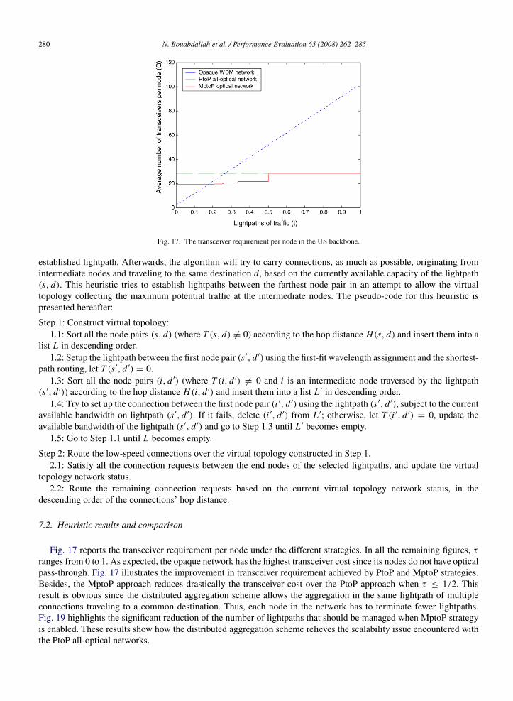
Fig. 17. The transceiver requirement per node in the US backbone.
established lightpath. Afterwards, the algorithm will try to carry connections, as much as possible, originating fromintermediate nodes and traveling to the same destination d, based on the currently available capacity of the lightpath(s, d). This heuristic tries to establish lightpaths between the farthest node pair in an attempt to allow the virtualtopology collecting the maximum potential traffic at the intermediate nodes. The pseudo-code for this heuristic ispresented hereafter:
Step 1: Construct virtual topology:1.1: Sort all the node pairs (s, d) (where T (s, d) 6= 0) according to the hop distance H(s, d) and insert them into a
list L in descending order.1.2: Setup the lightpath between the first node pair (s′, d ′) using the first-fit wavelength assignment and the shortest-
path routing, let T (s′, d ′) = 0.1.3: Sort all the node pairs (i, d ′) (where T (i, d ′) 6= 0 and i is an intermediate node traversed by the lightpath
(s′, d ′)) according to the hop distance H(i, d ′) and insert them into a list L ′ in descending order.1.4: Try to set up the connection between the first node pair (i ′, d ′) using the lightpath (s′, d ′), subject to the current
available bandwidth on lightpath (s′, d ′). If it fails, delete (i ′, d ′) from L ′; otherwise, let T (i ′, d ′) = 0, update theavailable bandwidth of the lightpath (s′, d ′) and go to Step 1.3 until L ′ becomes empty.
1.5: Go to Step 1.1 until L becomes empty.
Step 2: Route the low-speed connections over the virtual topology constructed in Step 1.2.1: Satisfy all the connection requests between the end nodes of the selected lightpaths, and update the virtual
topology network status.2.2: Route the remaining connection requests based on the current virtual topology network status, in the
descending order of the connections’ hop distance.
7.2. Heuristic results and comparison
Fig. 17 reports the transceiver requirement per node under the different strategies. In all the remaining figures, τ
ranges from 0 to 1. As expected, the opaque network has the highest transceiver cost since its nodes do not have opticalpass-through. Fig. 17 illustrates the improvement in transceiver requirement achieved by PtoP and MptoP strategies.Besides, the MptoP approach reduces drastically the transceiver cost over the PtoP approach when τ ≤ 1/2. Thisresult is obvious since the distributed aggregation scheme allows the aggregation in the same lightpath of multipleconnections traveling to a common destination. Thus, each node in the network has to terminate fewer lightpaths.Fig. 19 highlights the significant reduction of the number of lightpaths that should be managed when MptoP strategyis enabled. These results show how the distributed aggregation scheme relieves the scalability issue encountered withthe PtoP all-optical networks.
N. Bouabdallah et al. / Performance Evaluation 65 (2008) 262–285 281
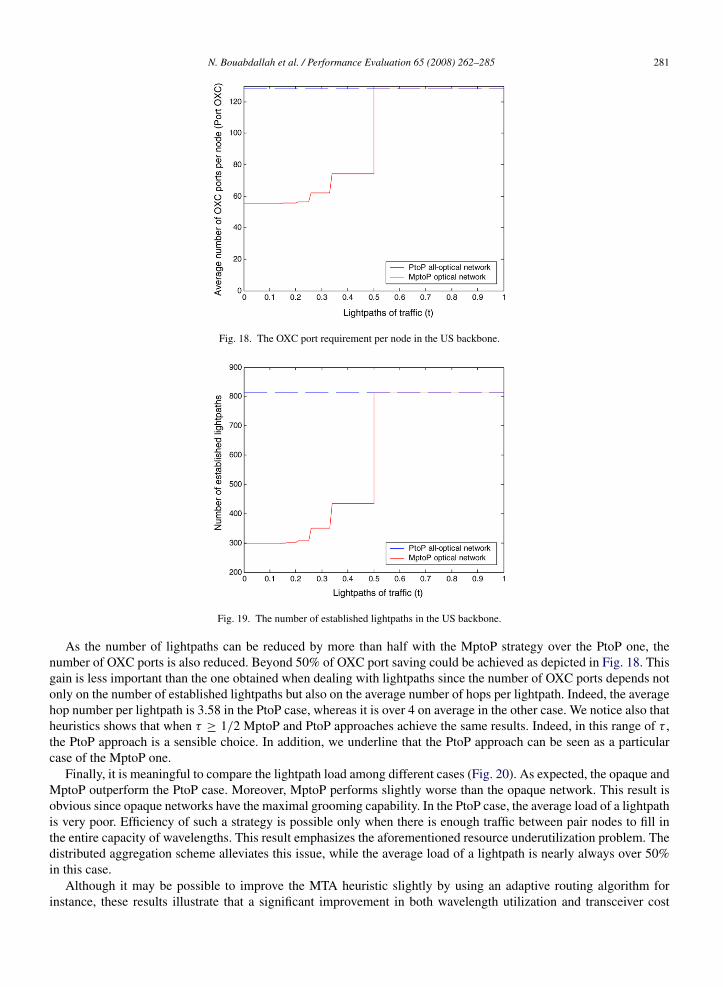
Fig. 18. The OXC port requirement per node in the US backbone.
Fig. 19. The number of established lightpaths in the US backbone.
As the number of lightpaths can be reduced by more than half with the MptoP strategy over the PtoP one, thenumber of OXC ports is also reduced. Beyond 50% of OXC port saving could be achieved as depicted in Fig. 18. Thisgain is less important than the one obtained when dealing with lightpaths since the number of OXC ports depends notonly on the number of established lightpaths but also on the average number of hops per lightpath. Indeed, the averagehop number per lightpath is 3.58 in the PtoP case, whereas it is over 4 on average in the other case. We notice also thatheuristics shows that when τ ≥ 1/2 MptoP and PtoP approaches achieve the same results. Indeed, in this range of τ ,the PtoP approach is a sensible choice. In addition, we underline that the PtoP approach can be seen as a particularcase of the MptoP one.
Finally, it is meaningful to compare the lightpath load among different cases (Fig. 20). As expected, the opaque andMptoP outperform the PtoP case. Moreover, MptoP performs slightly worse than the opaque network. This result isobvious since opaque networks have the maximal grooming capability. In the PtoP case, the average load of a lightpathis very poor. Efficiency of such a strategy is possible only when there is enough traffic between pair nodes to fill inthe entire capacity of wavelengths. This result emphasizes the aforementioned resource underutilization problem. Thedistributed aggregation scheme alleviates this issue, while the average load of a lightpath is nearly always over 50%in this case.
Although it may be possible to improve the MTA heuristic slightly by using an adaptive routing algorithm forinstance, these results illustrate that a significant improvement in both wavelength utilization and transceiver cost

282 N. Bouabdallah et al. / Performance Evaluation 65 (2008) 262–285
Fig. 20. The average wavelength utilization in the US backbone.
is possible with the distributed aggregation scheme. Synthetically and as previously seen with theoretical study, theMptoP approach always shows the smallest transceiver cost and leads to an efficient use of the wavelength resources.
8. Blocking probability comparison
In this section, we evaluate the blocking probability when using all underlying approaches. In addition to PtoPall-optical and opaque networks, we compare our MptoP solution to MH networks. Recall that MH networks can beseen as a hybrid solution between PtoP all-optical and opaque networks. To evaluate the gain introduced by our MptoPscheme over the MH networks, we use the heuristic proposed in [6]. Accordingly, we developed a new discrete-eventsimulation tool to calculate the blocking probability of dynamically arriving connection requests, under differentstrategies (PtoP all-optical networks, opaque networks, MH networks, and MptoP networks).
The following assumptions were made in our simulations: (1) The US backbone shown in Fig. 16 is used; (2) Eachlink in the network represents two fibers that are used to communicate in opposite directions. Each fiber carries 32wavelengths; (3) Each node is equipped with 20 transceivers and 40 OXC interfaces; 4) The shortest path adaptiverouting is used; (4) The first fit (FF) wavelength assignment approach is adopted; (5) Connection requests arrive ateach ingress node following the Poisson distribution, and the holding time of each request is exponentially distributed.The total traffic load offered to the network by each node is ρ = λ/µ, where λ and µ are the arrival and departure ratesat each ingress node, respectively; (6) The destination node of each arriving connection is randomly chosen amongthe N − 1 remaining edge nodes of the network; (6) The bandwidth requirement of each connection request T (s, d)
is randomly chosen in the interval [0, 1], so at most one lightpath is needed to carry any traffic request. We note that,in our simulations, we do not allow the traffic from the same connection to be bifurcated among multiple lightpaths.Finally, each value of the blocking probability has been calculated over multiple simulations to achieve very narrow97.5% confidence intervals.
In our simulations, each arriving connection tries first to use the lightpaths already established. If the availablebandwidth of the existing lightpaths is not sufficient, the connection will try to establish new lightpaths subject totransceiver, OXC port and wavelength constraints. Specifically, when the MptoP case is considered, the ingress node sof an arriving connection request with destination d , looks first for a pass-through lightpath traveling towards the sameegress node d which has sufficient available bandwidth. Otherwise, node s tries to establish a new lightpath subjectto resource availability. If there are not enough resources to satisfy the connection request, it is simply blocked. In thesame way, when the MH approach is adopted, the source node s first tries to find an available route through the existinglightpaths. In this case, the connection may span multiple lightpaths before reaching its destination. If such a route isnot available, the connection tries to establish the missing lightpaths (end-to-end lightpath, or missing segments alongthe route) to reach its destination.
Fig. 21 plots different blocking probabilities as a function of the network load ρ. We observe that the opaquestrategy always leads to the maximum blocking probability. This is mainly due to the lack of available transceivers.

N. Bouabdallah et al. / Performance Evaluation 65 (2008) 262–285 283
Fig. 21. Blocking probability evolution with the network load.
Indeed, the total network capacity (in terms of transceiver equipments) is quickly exhausted, since the nodes do notpermit transit connections to pass through optically. The PtoP all-optical circuit-switched strategy slightly alleviatesthis problem due to the optical transparency. Even so, the blocking probability remains relatively high due to the greatnumber of P-to-P lightpaths that are required in this case. These lightpaths require a large number of OXC interfacesand wavelengths. The MH and MptoP schemes reduce significantly the blocking probability since they alleviate thescalability issue of the PtoP all-optical networks by increasing their grooming capacity.
In addition, the MptoP scheme outperforms the MH scheme, since it requires fewer transceivers and OXCinterfaces. Indeed, the MptoP scheme improves the PtoP all-optical circuit-switched network grooming capacitywhile conserving its entire transparency as opposed to the MH approach, where electronic grooming is needed atsome network nodes. This active electronic processing operation enables an MH network to save in components overPtoP all-optical and opaque networks, but requires additional equipment, such as OXC interfaces and transceivers,when compared to the passive MptoP insertion. In addition, the MptoP scheme outperforms the MH scheme, sinceit requires fewer transceivers and OXC interfaces. Indeed, the MptoP scheme improves the PtoP all-optical circuit-switched network grooming capacity while conserving its entire transparency as opposed to the MH approach, whereelectronic grooming is needed at some network nodes. This active electronic processing operation enables an MHnetwork to save in components over PtoP all-optical and opaque networks, but requires additional equipment, such asOXC interfaces and transceivers, when compared to the passive MptoP insertion.
Fig. 22 plots the blocking probability as a function of the bandwidth requirement T (s, d) of each connectionrequest. In this case, we consider a uniform traffic matrix, i.e., T (s, d) = τ∀s and d, where τ ranges from 0 to 1, andρ = 10. This figure illustrates the general trade-off among the different strategies. According to the value of τ , we getdifferent optimal solutions. At one extreme, when each node transmits close to the wavelength capacity to each othernode, the PtoP all-optical circuit-switched approach is the best solution as the network is already well utilized withoutgrooming. At the other extreme, when the total demand from each node is a small fraction of the wavelength capacity,the opaque strategy stands out as the best solution due to its grooming capability. In most cases, when the demand ismoderate to normal, MH and MptoP schemes generally present the best solutions, with an advantage to the MptoPscheme. We note that MH, MptoP and PtoP all-optical strategies achieve almost the same results when τ > 1/2. Thisis due to the fact that we do not allow traffic belonging to the same connection request to be bifurcated among multiplelightpaths. In doing so, grooming multiple connections on the same lightpath is no more possible when τ > 1/2.
9. Conclusion
We have proposed a distributed aggregation approach in all-optical wavelength routed networks, relying on themultipoint-to-point lightpath concept. This approach combines the merits of both the optical bypass of all-opticalwavelength routing and the multiplexing gain of sub-wavelength routing. In order to assess the efficiency of ourproposal, all underlying network costs were compared. Theoretical study and heuristic approach showed that our

284 N. Bouabdallah et al. / Performance Evaluation 65 (2008) 262–285
Fig. 22. Blocking probability evolution with the bandwidth requirement per connection.
proposal always enables the smallest transceiver cost and leads to an efficient use of the wavelength resources.Distributed aggregation reduces the wasted bandwidth problem and alleviates the scalability issues encountered inall-optical wavelength routed networks while preserving the benefits of optical bypass.
References
[1] I. Chlamtac, A. Farago, T. Zhang, Lightpath (wavelength) routing in large WDM networks, IEEE J. Select. Areas Commun. 14 (1996)909–913.
[2] D. Banerjee, B. Mukherjee, Wavelength-routed optical networks: Linear formulation, resource budgeting tradeoffs, and a reconfigurationstudy, IEEE/ACM Trans. Netw. 8 (2000) 598–607.
[3] D. Banerjee, B. Mukherjee, A practical approach for routing and wavelength assignment in large wavelength-routed optical networks, IEEEJ. Select. Areas Commun. 14 (1996) 903–908.
[4] Mike J. O’ Mahony, et al., The application of optical packet switching in future communication networks, IEEE Commun. Mag. (2001)128–135.
[5] T. Battistilli, H. Perros, An introduction to optical burst switching, IEEE Commun. Mag. 41 (8) (2003) S10–S15.[6] K. Zhu, B. Mukherjee, Traffic grooming in an optical WDM mesh network, IEEE J. Select. Areas Commun. 20 (2002) 122–133.[7] B. Mukherjee, Optical Communication Networks, Mc-Graw-Hill, New York, 1997.[8] M. Mellia, E. Leonardi, M. Feletig, R. Gaudino, F. Neri, Exploiting OTDM technology in WDM networks, in: Proc. IEEE INFOCOM’2002,
New York, USA, June 2002, pp. 1822–1831.[9] N. Bouabdallah, et al. Matching fairness and performance by preventive traffic control in optical multiple access networks, in: Proc. of
OptiComm’2003, Dallas, October 2003.[10] G. Kramer, B. Mukherjee, G. Pesavento, Ethernet PON (ePON): Design and analysis of an optical access network, Phot. Net. Commun. 3 (3)
(2001) 307–319.[11] R. Gaudino, et al. RINGO: A WDM ring optical packet network demonstrator, in: Proc. of ECOC’01, vol. 4, Amsterdam, Netherlands,
September 2001, pp. 620–621.[12] N. Bouandallah, A.L. Beylot, E. Dotaro, G. Pujolle, Resolving the fairness issue in bus-based optical access networks, IEEE J. Select. Areas
Commun. 23 (8) (2005) 1444–1457.[13] O. Gerstel, R. Ramswami, Cost effective traffic grooming in WDM rings, in: Proc. of IEEE Infocom’1998, vol. 1, April 1998, pp. 69–77.[14] G. Kramer, G. Pesavento, Ethernet passive optical network (EPON): Building a next-generation optical access network, IEEE Commun. Mag.
(2002) 66–73.[15] M.G. Hluchyj, M.J. Karol, Shufflenet: An application of generalized perfect shuffles to multihop lightwave networks, J. Lightwave Technol.
9 (1991) 1386–1397.[16] K.N. Sivarajan, R. Ramaswami, Lightwave networks based on de Bruijn graphs, IEEE/ACM Trans. Netw. 2 (1994) 70–79.[17] I. Chlamtac, A. Ganz, G. Karmi, Lightnets: Topologies for highspeed optical networks, J. Lightwave Technol. 11 (1993) 951–961.[18] N.F. Maxemchuk, Routing in the Manhattan street network, IEEE Trans. Commun. Com-35 (1987) 503–512.[19] C.P. Ravikumar, T. Rai, V. Verma, Kautz graphs as attractive logical topologies in multihop lightwave networks, Comput. Commun. 20 (1997)
1259–1269.[20] N. Bouabdallah, E. Dotaro, N. LeSauze, L. Ciavaglia, G. Pujolle, Distributed aggregation in all-optical wavelength routed networks, in: Proc.
of IEEE ICC’2004, Paris, France, June 2004.

N. Bouabdallah et al. / Performance Evaluation 65 (2008) 262–285 285
Nizar Bouabdallah received the B.S. degree in telecommunications engineering from Ecole Superieur desCommunications (Sup’Com), Tunis, Tunisia, in 2001, and the M.S. and Ph.D. degrees in network and computer sciencefrom the University of Paris VI, Paris, France, in 2002 and 2004, respectively. He joined Alcatel Research Laboratories,Marcoussis, France, in 2002, while working on his Ph.D. degree. In 2005, he was with the North Carolina State University,Raleigh, NC, USA, as a Postdoctoral Fellow.
He is currently a researcher at INRIA (Institut National de Recherche en Informatique et en Automatique). SinceFebruary 2007, he has been a Visitor Researcher at the School of Computer Science, University of Waterloo, Waterloo,ON, Canada. His research interests include optical networking, wireless and sensor networks, performance evaluation,network planning and modeling, as well as control and management architectures.
Guy Pujolle received the Ph.D. and These d’Etat degrees in computer science from the University of Paris IX and XI,Paris, France, in 1975 and 1978, respectively.
He is currently a Professor at the University of Paris VI. He is Chairman of IFIP Working Group 6.2 on Networkand Internetwork Architectures. He is a pioneer in high-speed networking, having led the development of the first gigabitnetwork tested in 1980. He was also a European expert involved in the development of European high-speed networks. Heis a cofounder and CSO of QoSMOS and Ucopia Communications. He is an Editor for the International Journal of NetworkManagement, ACMWINET, and Ad Hoc Networks Journal. Dr. Pujolle is an Editor for the IEEE Tutorials and Surveys. Heis a Governor of the International Council for Computer Communications.
Harry Perros is a Professor of Computer Science, an Alumni Distinguished Graduate Professor, and the ProgramCoordinator of the Master of Science degree in Computer Networks at NC State University.
He received the B.Sc. degree in Mathematics in 1970 from Athens University, Greece, the M.Sc. degree in OperationalResearch with Computing from Leeds University, England, in 1971, and the Ph.D. degree in Operations Research fromTrinity College Dublin, Ireland, in 1975. He has held visiting faculty positions at INRIA, Rocquencourt, France (1979),NORTEL, Research Triangle Park, North Carolina (1988–89 and 1995–96), University of Paris 6, France (1995–96, 2000,and 2002), University of Paris 13, France (2005–2006), and Victoria University, Wellington, New Zealand (2006).
He has published extensively in the area of performance modelling of computer and communication systems, and hehas organized several national and international conferences. He has also published three print books: Queueing Networkswith Blocking: Exact and Approximate Solutions, Oxford University Press 1994, An Introduction to ATM Networks, Wiley
2001, Connection-Oriented Networks, Wiley 2005, and an e-book Computer Simulation Techniques—The Definitive Introduction, 2002.In 1995 he founded the IFIP Working Group 6.3 on the Performance of Communication Systems, and he was the chairman from 1995 to 2002.
From 2004 to 2006, he was the chairman of the IFIP Working Group 6.10 on Optical Networks. He is also a member of IFIP Working Groups 6.2and 7.3, a member of the National Lambda Rail Network Research Council, and an IEEE Senior Member. He is also an associate Editor for thePerformance EvaluationJournal, and the Telecommunications SystemsJournal.
His current research interests are in the areas of optical networks, grids, and service engineering.


![Point-to-Multipoint and Multipoint-to-Multipoint · PDF filedefined by IEEE 802.1Qay [2] is representative carrier Ethernet . Abstract — We have implemented point-to-multipoint (PtMP)](https://img.pdfslide.net/doc/110x75/5a75c0147f8b9a4b538cb6cd/point-to-multipoint-and-multipoint-to-multipoint-defined-by-ieee-8021qay.jpg)