Embed Size (px)
Citation preview
Multipulse modulation schemes for 100 Gigabit Ethernet
J. D. Ingham, R. V. Penty, I. H. White University of Cambridge, Department of Engineering, Cambridge, UK
D. G. Cunningham Avago Technologies, Framlingham Technology Centre, Framlingham, UK
Acknowledgment: Engineering and Physical Sciences Research Council
• Principle of multipulse modulation
• Motivation for a 100 Gb/s multipulse scheme
• Simulation results
• Power budget comparison with PAM4
• Performance improvement by interference cancellation
• Further power budget comparison with PAM4
• Power consumption
• Experimental result
• Conclusions
• References
Contents
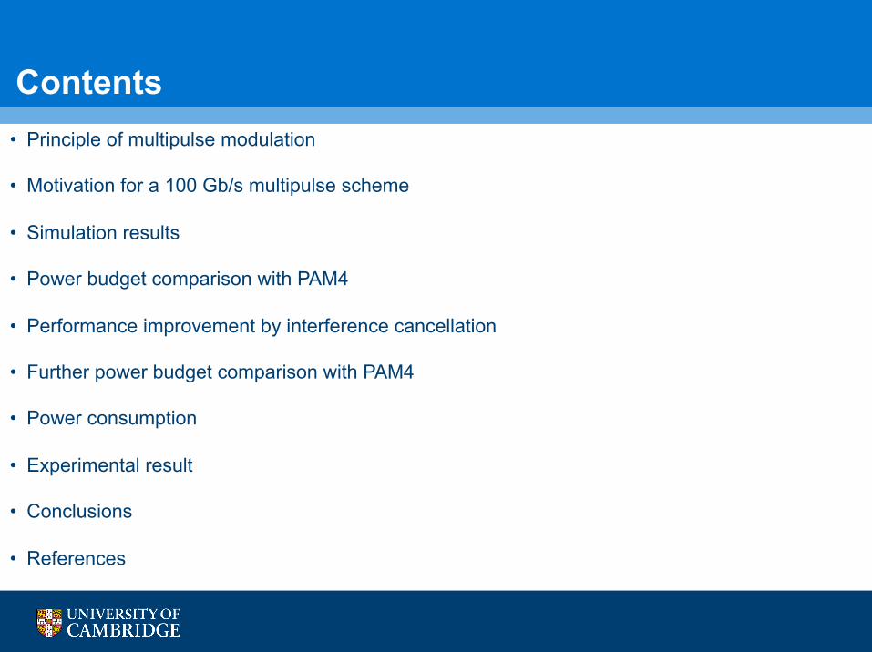
Principle of multipulse modulation • Consider a simple scheme using three pulses
• Pulse shapes: biphase (BP), modified biphase (MBP) and NRZ:
MBP
NRZ
BP 0
-1
+1
0
-1
+1
0
+1
Multiplying any pair of these
pulses, it is evident that they are
orthogonal, i.e. they have zero
cross-correlation
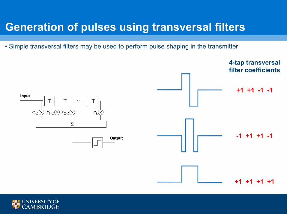
Generation of pulses using transversal filters
4-tap transversal filter coefficients
+1 +1 -1 -1
-1 +1 +1 -1
+1 +1 +1 +1
• Simple transversal filters may be used to perform pulse shaping in the transmitter
Comments on multipulse modulation • Advantages include:
• The use of multiple pulses, rather than multiple levels, avoids the large relative receiver sensitivity penalty seen in links using PAMn, where n > 2
• In effect, the multipulse receiver processes multiple NRZ signals from the outputs of the matched filters, which may simplify clock recovery and decision circuits relative to PAM
• The Tx pulse shaping and Rx matched filtering may be performed using simple and potentially low-power transversal filters. The delay lines may be implemented as passive analog structures
• Incoming independent data channels may be directly shaped to a corresponding pulse, without complicated symbol mapping, gearboxes etc. The number of pulses used may be chosen to be appropriate to the application
• Disadvantages include:
• The bandwidth requirements are generally larger than a corresponding PAM scheme
• Bandwidth limitations result in interference between pulses, although this may be cancelled
• The horizontal eye opening at the outputs of the matched filters may be restricted
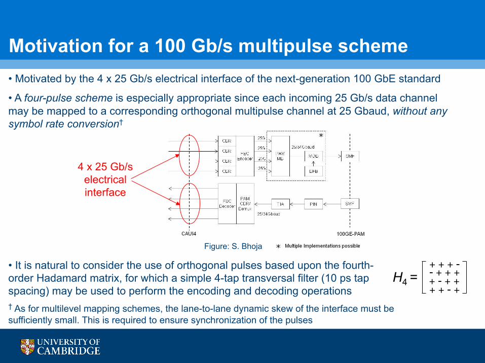
Motivation for a 100 Gb/s multipulse scheme • Motivated by the 4 x 25 Gb/s electrical interface of the next-generation 100 GbE standard
• A four-pulse scheme is especially appropriate since each incoming 25 Gb/s data channel may be mapped to a corresponding orthogonal multipulse channel at 25 Gbaud, without any symbol rate conversion†
4 x 25 Gb/s electrical interface
Figure: S. Bhoja
† As for multilevel mapping schemes, the lane-to-lane dynamic skew of the interface must be sufficiently small. This is required to ensure synchronization of the pulses
• It is natural to consider the use of orthogonal pulses based upon the fourth-order Hadamard matrix, for which a simple 4-tap transversal filter (10 ps tap spacing) may be used to perform the encoding and decoding operations
H4 =
+ + + - - + + + + - + + + + - +
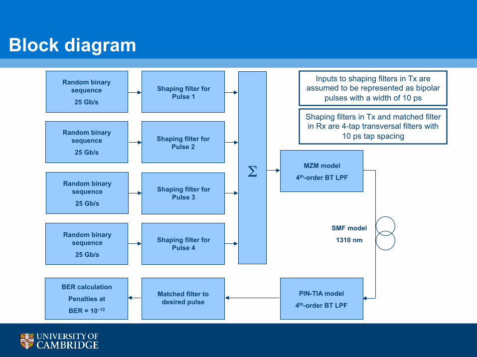
Block diagram
Random binary sequence
25 Gb/s
Shaping filter for Pulse 1
Random binary sequence
25 Gb/s
Random binary sequence
25 Gb/s
Random binary sequence
25 Gb/s
Shaping filter for Pulse 2
Shaping filter for Pulse 3
Shaping filter for Pulse 4
Σ MZM model
4th-order BT LPF
BER calculation
Penalties at
BER = 10–12
Matched filter to desired pulse
PIN-TIA model
4th-order BT LPF
Shaping filters in Tx and matched filter in Rx are 4-tap transversal filters with
10 ps tap spacing
SMF model
1310 nm
Inputs to shaping filters in Tx are assumed to be represented as bipolar
pulses with a width of 10 ps
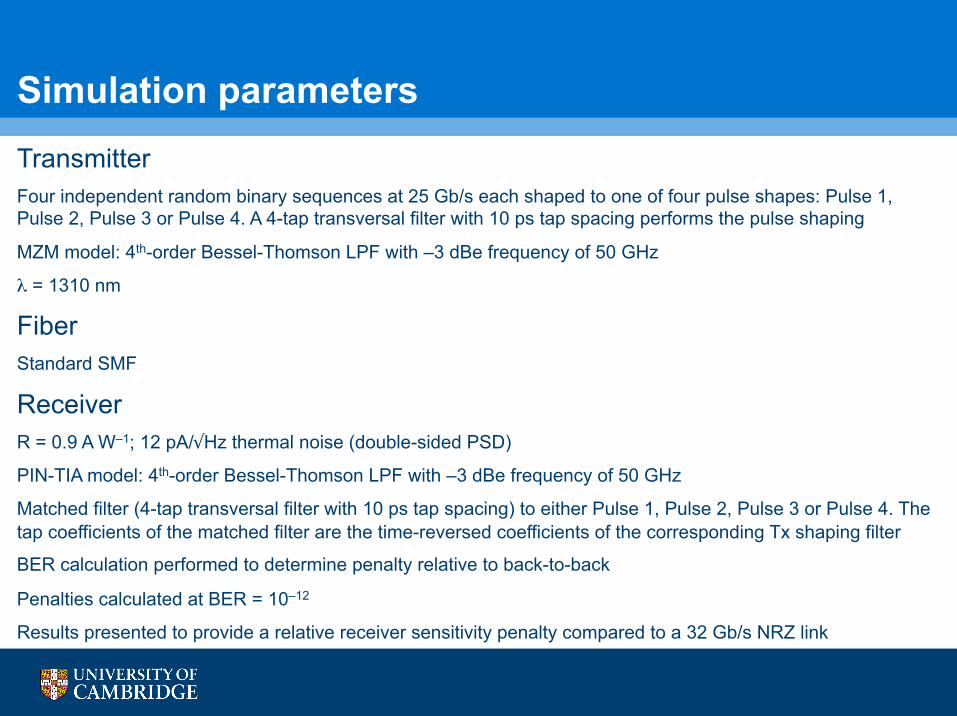
Simulation parameters Transmitter Four independent random binary sequences at 25 Gb/s each shaped to one of four pulse shapes: Pulse 1, Pulse 2, Pulse 3 or Pulse 4. A 4-tap transversal filter with 10 ps tap spacing performs the pulse shaping
MZM model: 4th-order Bessel-Thomson LPF with –3 dBe frequency of 50 GHz
λ = 1310 nm
Fiber Standard SMF
Receiver R = 0.9 A W–1; 12 pA/√Hz thermal noise (double-sided PSD)
PIN-TIA model: 4th-order Bessel-Thomson LPF with –3 dBe frequency of 50 GHz
Matched filter (4-tap transversal filter with 10 ps tap spacing) to either Pulse 1, Pulse 2, Pulse 3 or Pulse 4. The tap coefficients of the matched filter are the time-reversed coefficients of the corresponding Tx shaping filter
BER calculation performed to determine penalty relative to back-to-back
Penalties calculated at BER = 10–12
Results presented to provide a relative receiver sensitivity penalty compared to a 32 Gb/s NRZ link
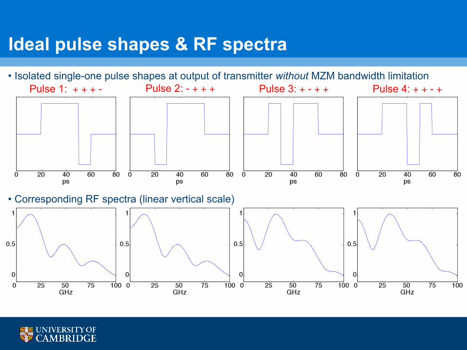
Ideal pulse shapes & RF spectra • Isolated single-one pulse shapes at output of transmitter without MZM bandwidth limitation
• Corresponding RF spectra (linear vertical scale)
Pulse 1: + + + - Pulse 2: - + + + Pulse 3: + - + + Pulse 4: + + - +
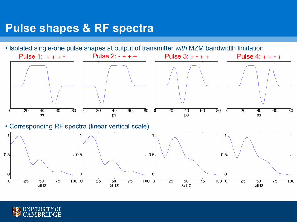
Pulse shapes & RF spectra • Isolated single-one pulse shapes at output of transmitter with MZM bandwidth limitation
• Corresponding RF spectra (linear vertical scale)
Pulse 1: + + + - Pulse 2: - + + + Pulse 3: + - + + Pulse 4: + + - +
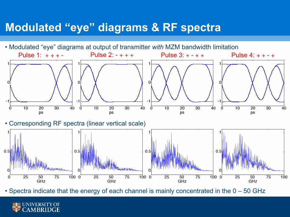
Modulated “eye” diagrams & RF spectra
• Spectra indicate that the energy of each channel is mainly concentrated in the 0 – 50 GHz range
Pulse 1: + + + - Pulse 2: - + + + Pulse 3: + - + + Pulse 4: + + - + • Modulated “eye” diagrams at output of transmitter with MZM bandwidth limitation
• Corresponding RF spectra (linear vertical scale)
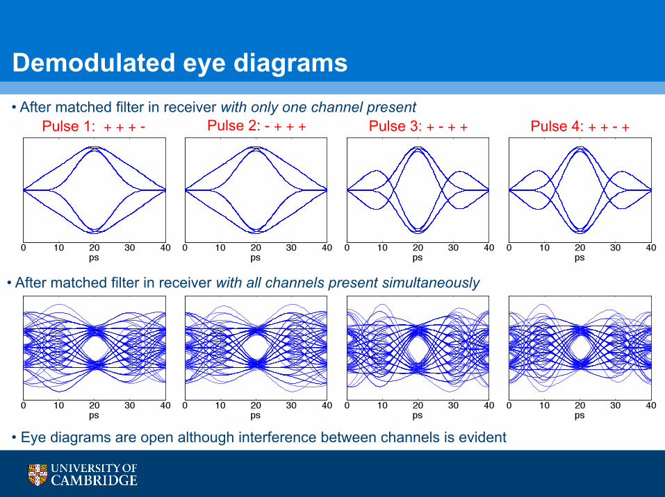
Demodulated eye diagrams • After matched filter in receiver with only one channel present
• After matched filter in receiver with all channels present simultaneously
Pulse 1: + + + - Pulse 2: - + + + Pulse 3: + - + + Pulse 4: + + - +
• Eye diagrams are open although interference between channels is evident
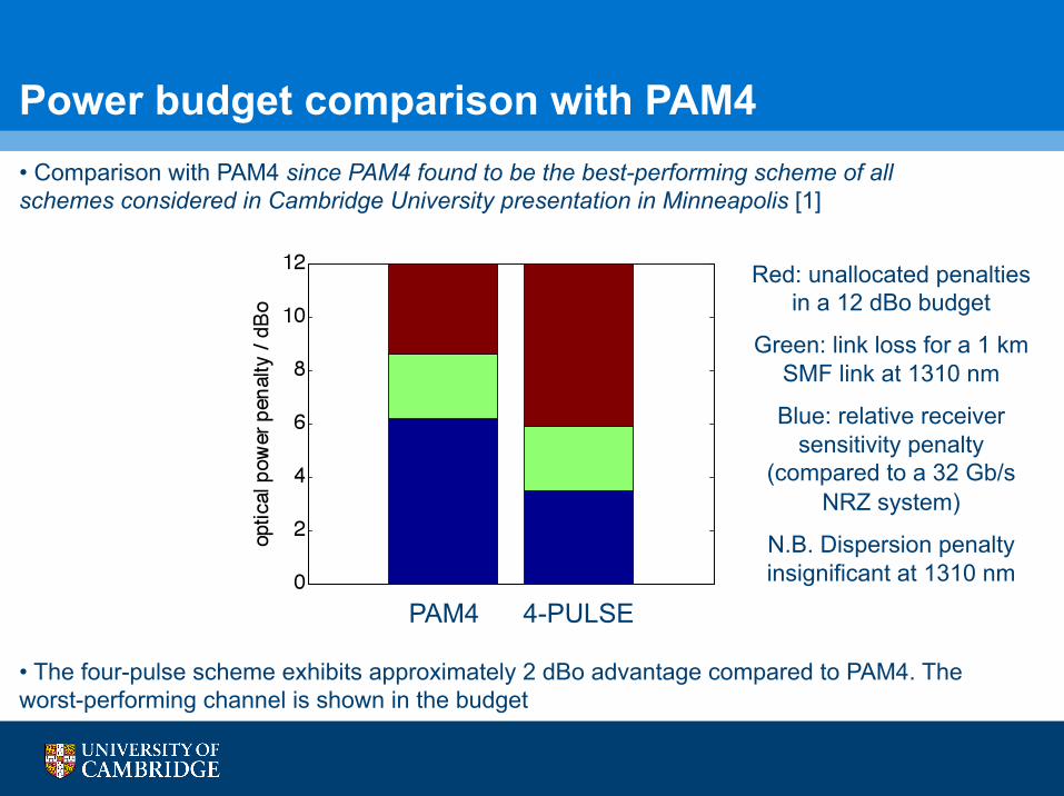
Power budget comparison with PAM4 • Comparison with PAM4 since PAM4 found to be the best-performing scheme of all schemes considered in Cambridge University presentation in Minneapolis [1]
• The four-pulse scheme exhibits approximately 2 dBo advantage compared to PAM4. The worst-performing channel is shown in the budget
PAM4 4-PULSE
Red: unallocated penalties in a 12 dBo budget
Green: link loss for a 1 km SMF link at 1310 nm
Blue: relative receiver sensitivity penalty
(compared to a 32 Gb/s NRZ system)
N.B. Dispersion penalty insignificant at 1310 nm
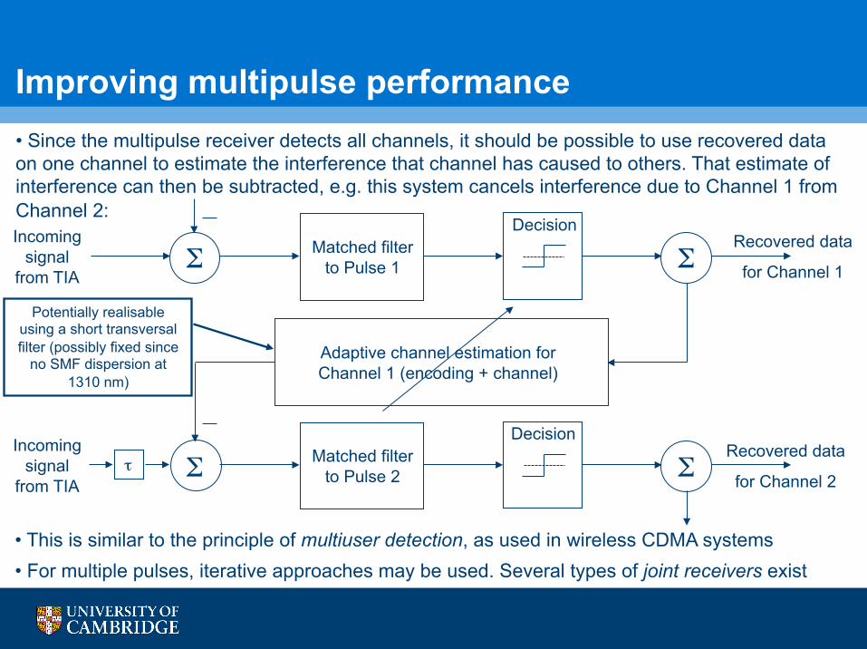
Improving multipulse performance • Since the multipulse receiver detects all channels, it should be possible to use recovered data on one channel to estimate the interference that channel has caused to others. That estimate of interference can then be subtracted, e.g. this system cancels interference due to Channel 1 from Channel 2:
• This is similar to the principle of multiuser detection, as used in wireless CDMA systems • For multiple pulses, iterative approaches may be used. Several types of joint receivers exist
Incoming signal
from TIA Σ Matched filter
to Pulse 1 Σ
Adaptive channel estimation for Channel 1 (encoding + channel)
Recovered data
for Channel 1
Incoming signal
from TIA Σ Matched filter
to Pulse 2 Σ Recovered data
for Channel 2
Decision
Decision
Potentially realisable using a short transversal filter (possibly fixed since
no SMF dispersion at 1310 nm)
τ
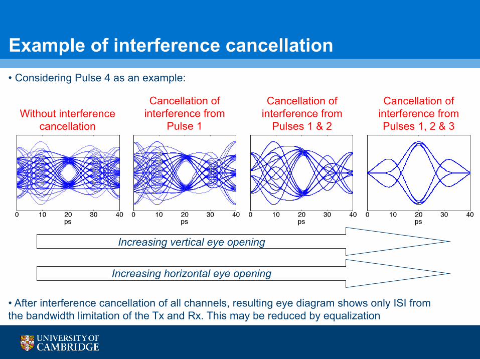
Example of interference cancellation • Considering Pulse 4 as an example:
Increasing vertical eye opening
Without interference cancellation
Cancellation of interference from
Pulse 1
Cancellation of interference from
Pulses 1 & 2
Cancellation of interference from Pulses 1, 2 & 3
Increasing horizontal eye opening
• After interference cancellation of all channels, resulting eye diagram shows only ISI from the bandwidth limitation of the Tx and Rx. This may be reduced by equalization
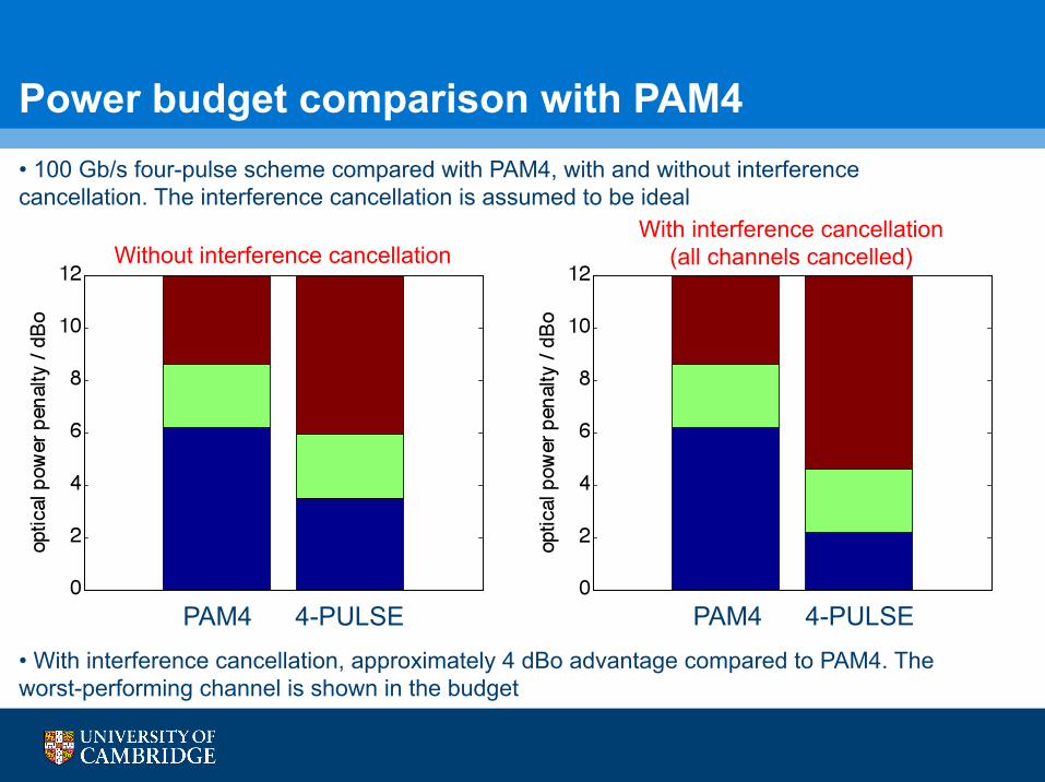
Power budget comparison with PAM4 • 100 Gb/s four-pulse scheme compared with PAM4, with and without interference cancellation. The interference cancellation is assumed to be ideal
PAM4 4-PULSE
Without interference cancellation
• With interference cancellation, approximately 4 dBo advantage compared to PAM4. The worst-performing channel is shown in the budget
PAM4 4-PULSE
With interference cancellation (all channels cancelled)
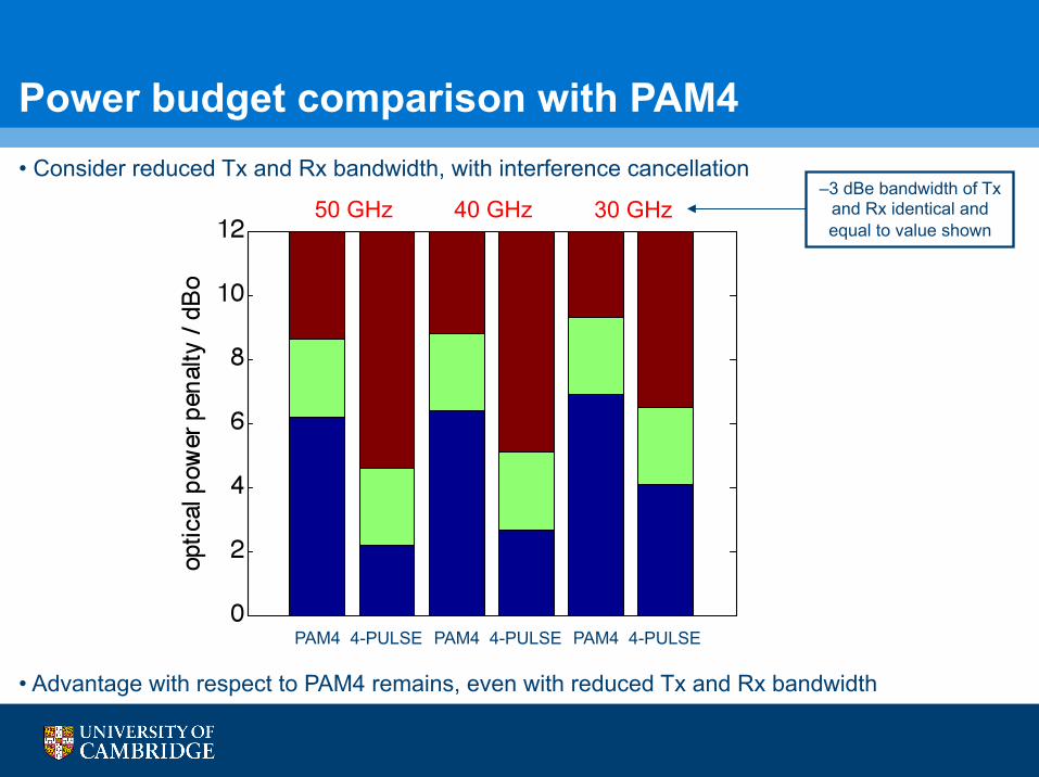
Power budget comparison with PAM4 • Consider reduced Tx and Rx bandwidth, with interference cancellation
50 GHz 40 GHz 30 GHz –3 dBe bandwidth of Tx
and Rx identical and equal to value shown
• Advantage with respect to PAM4 remains, even with reduced Tx and Rx bandwidth
PAM4 4-PULSE PAM4 4-PULSE PAM4 4-PULSE
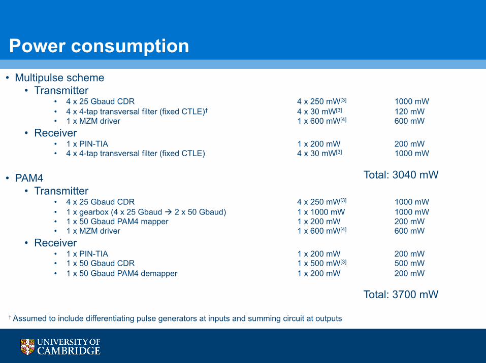
• Multipulse scheme • Transmitter
• 4 x 25 Gbaud CDR 4 x 250 mW[3] 1000 mW • 4 x 4-tap transversal filter (fixed CTLE)† 4 x 30 mW[3] 120 mW • 1 x MZM driver 1 x 600 mW[4] 600 mW
• Receiver • 1 x PIN-TIA 1 x 200 mW 200 mW • 4 x 4-tap transversal filter (fixed CTLE) 4 x 30 mW[3] 1000 mW
• PAM4
• Transmitter • 4 x 25 Gbaud CDR 4 x 250 mW[3] 1000 mW • 1 x gearbox (4 x 25 Gbaud 2 x 50 Gbaud) 1 x 1000 mW 1000 mW • 1 x 50 Gbaud PAM4 mapper 1 x 200 mW 200 mW • 1 x MZM driver 1 x 600 mW[4] 600 mW
• Receiver • 1 x PIN-TIA 1 x 200 mW 200 mW • 1 x 50 Gbaud CDR 1 x 500 mW[3] 500 mW • 1 x 50 Gbaud PAM4 demapper 1 x 200 mW 200 mW
Power consumption
† Assumed to include differentiating pulse generators at inputs and summing circuit at outputs
Total: 3040 mW
Total: 3700 mW
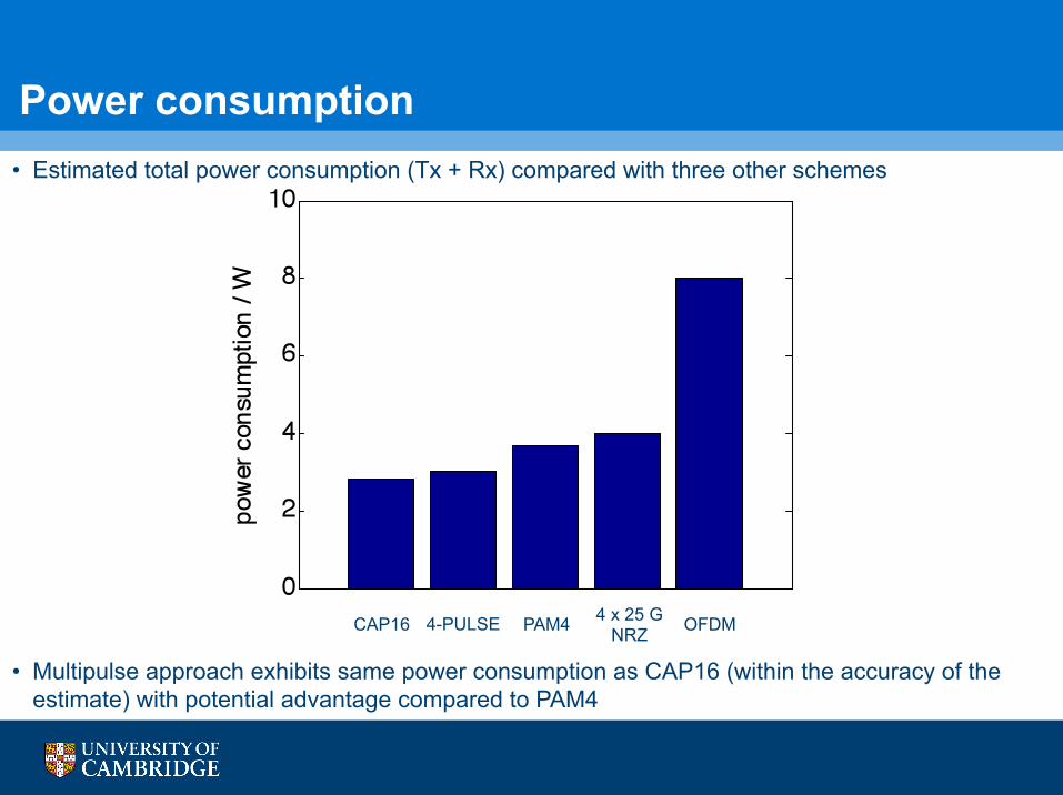
Power consumption • Estimated total power consumption (Tx + Rx) compared with three other schemes
CAP16 4-PULSE PAM4 OFDM
• Multipulse approach exhibits same power consumption as CAP16 (within the accuracy of the estimate) with potential advantage compared to PAM4
4 x 25 G NRZ
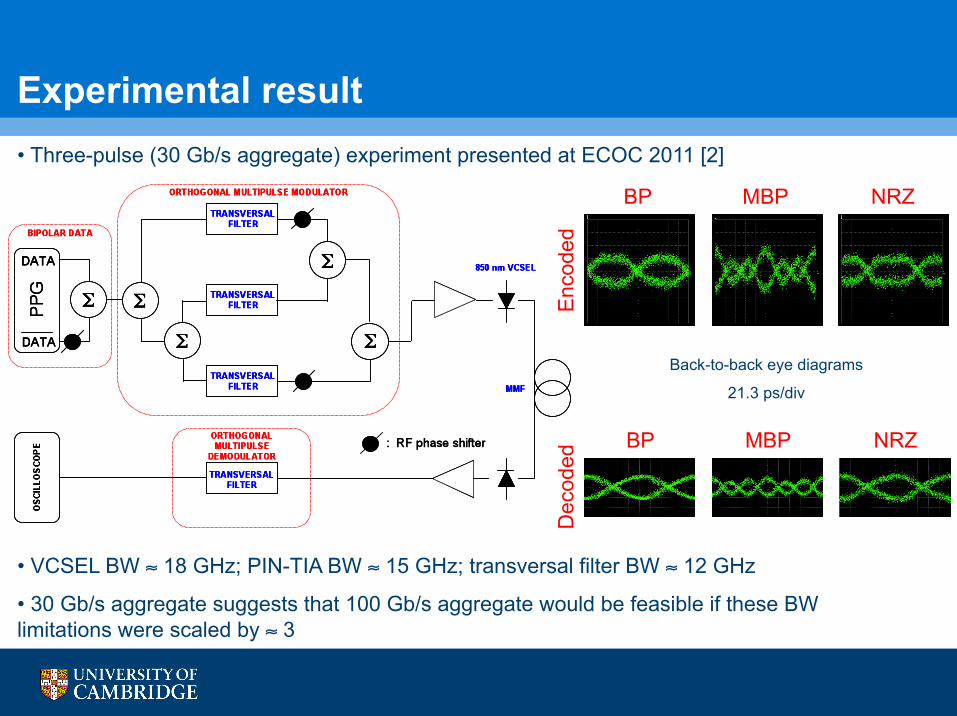
Experimental result • Three-pulse (30 Gb/s aggregate) experiment presented at ECOC 2011 [2]
• VCSEL BW ≈ 18 GHz; PIN-TIA BW ≈ 15 GHz; transversal filter BW ≈ 12 GHz
• 30 Gb/s aggregate suggests that 100 Gb/s aggregate would be feasible if these BW limitations were scaled by ≈ 3
Back-to-back eye diagrams
21.3 ps/div
BP MBP NRZ
Enc
oded
D
ecod
ed BP MBP NRZ
Conclusions • Multipulse schemes considered for 100 GbE links
• A four-pulse 4 x 25 Gb/s scheme is highly relevant to the 4 x 25 Gb/s electrical interface of 100 GbE, avoiding symbol mapping
• The multilevel penalty associated with PAMn, where n > 2, is avoided
• Power budgets indicate the potential for superior performance compared with the best performing scheme presented at the last meeting (PAM4)
• A receiver which exploits knowledge of all pulses has the potential to improve the performance further
• Experimental work at 30 Gb/s with low-bandwidth components suggests feasibility of 100 Gb/s
References [1] J. L. Wei, J. D. Ingham, R. V. Penty, I. H. White, “Performance studies of 100 Gigabit Ethernet enabled by advanced modulation formats,” IEEE 802.3 Interim Meeting: IEEE 802.3 Next Generation 40 Gb/s and 100 Gb/s Optical Ethernet Study Group. Minneapolis, MN, USA, May 2012
[2] J. D. Ingham, R. V. Penty, I. H. White, D. G. Cunningham, P. Westbergh, J. Gustavsson, Å. Haglund, A. Larsson, “Orthogonal multipulse modulation for next-generation datacommunication links,” 37th European Conference on Optical Communication, paper Tu.3.C.2. Geneva, Switzerland, September 2011
[3] J. King, S. Bhoja, “MMF links, EQ and FEC,” IEEE 802 Plenary Meeting: IEEE 802.3 Next Generation 40 Gb/s and 100 Gb/s Optical Ethernet Study Group. Atlanta, GA, USA, November 2011
[4] S. Bhoja, “Study of PAM modulation for 100GE over a single laser,” IEEE 802.3 Interim Meeting: IEEE 802.3 Next Generation 40 Gb/s and 100 Gb/s Optical Ethernet Study Group. Newport Beach, CA, USA, January 2012