Embed Size (px)
Citation preview
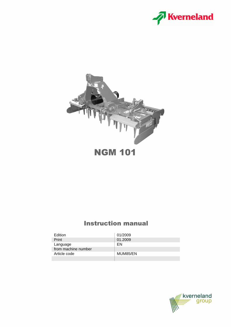
NGM 101
Instruction manual
Edition 01/2009Print 01.2009Language ENfrom machine numberArticle code MUM85/EN
Machine identificationTo enable your dealer to help quickly and efficiently, you need to supply certain information about your ma-chine.Use the spaces below to record this information.
Designation
Serial number
Accessories
Dealer's address
Manufacturer's address
Copyright owned by Kverneland Group Modena, ITALY. All copying, transcription to other media, translation and use of extracts or parts is pro-hibited without the express authorization of Kverneland. All right reserved. The contents of this instruction manual are subject to modifcation with-out prior notice. We reserve the right to make technical modifcations.
NGM...................
Kverneland Group ModenaStrada Ponte Alto, 7441100 Modena ITALIATelefono +39 059 380 511
Contents
3
Contents
Introduction . . . . . . . . . . . . . . . . . . . . . . . . . . 4About this manual 4Meaning of symbols 4
Safety . . . . . . . . . . . . . . . . . . . . . . . . . . . . . . . 5For your safety 5Other regulations to be observed 5Safety symbols 5Meanings of the safety symbols 5Positions of the safety warning labels 7Sound pressure levels 7Lifting 8
Getting to know your machine . . . . . . . . . . 9Intended use 9Key to parts 9Technical specifications 10
Delivery and preparation of the machine . 11Checking the machine 11Preparation 11
Hitching the machine . . . . . . . . . . . . . . . . . 13
Preparation for work . . . . . . . . . . . . . . . . . 16Checking the levels 16Working speed 17Speed selection 17
Transporting the implement on the road . 19
Preparations in the field . . . . . . . . . . . . . . . 20Lateral stone guards 20Adjusting the working depth 20Adjustment of the levelling bar 21Positioning the track eradicator 22
Cleaning, maintenance and storage . . . . . 23Safe storage 23Winter storage 23
Maintenance . . . . . . . . . . . . . . . . . . . . . . . . 24Changing the oil 24Comparative classification of viscosity 26Replacing the tines of the harrow 27Replacing the tines with bolt fastening 27Replacing the tines with rapid fastening 28Packer roller 29Disc rollers 30
Accessories . . . . . . . . . . . . . . . . . . . . . . . . 32Universal seed drill attachment 32Hydraulic seed drill attachment 34
Accord seed drill triangular mounting frame 36
Troubleshooting . . . . . . . . . . . . . . . . . . . . . 37
Warranty . . . . . . . . . . . . . . . . . . . . . . . . . . . . 38Guide to warranty conditions 38Service information 38
Disposal of the machine . . . . . . . . . . . . . . . 39
EC Declaration of Conformity . . . . . . . . . . 40
Index . . . . . . . . . . . . . . . . . . . . . . . . . . . . . . . 41

4
Introduction
Introduction
About this manual This Instruction Manual is addressed to qualified users or experiencedagricultural operatives who have received suitable training on the useof the machine.
For your safety Before hitching up or operating the machine, please familiariseyourself with the contents of this Instruction Manual. This will ensurethat you achieve optimum results and work in conditions of safety.
The manufacturer accepts no liability for any damage or operatingproblems caused by failure to adhere to the instructions given in thismanual.
For the employerAll personnel must receive proper training in the use of the machine(at least once a year) in accordance with the guidelines on safety atwork. Unauthorized and untrained persons are prohibited from using themachine.
Training Your dealer will provide instructions on the operation and care of themachine.
Meaning of symbols
The following symbols are used in this manual as an aid tocomprehension: • a bullet point denotes the individual items in a list > a triangle indicates the operations to be carried out -->an arrow refers the reader to information in other sections of themanual
Furthermore, other graphic symbols are used to help the reader to findthe relative instructions more quickly:
NOTE The term "Note" is used to indicate suggestions and notes on use ofthe machine.
The wrench symbol denotes suggestions for attachment oradjustment of the machine.
The warning triangle is used to highlight important safety warnings.Failure to observe these warnings may result in: • Serious malfunction of the machine • Damage to the machine • Personal injury or accidents
An asterisk indicates examples provided to aid comprehension of theinstructions in the text.

Safety
5
Safety
For your safety This section contains general safety warnings. The individual sectionsof manual contain additional specific safety warnings which are notincluded in this section. Take particular care to observe the safetywarnings • for your own personal safety • for the safety of other persons and • to prevent damage to the machine.
Improper use of the machine and other agricultural equipment cancreate serious hazards. Always work with maximum care andattention and never in haste.
The employer should:At regular intervals and in accordance with legal requirements, ensurethat all persons working with the machine are informed of these safetywarnings.
Other regulations to be observed
Respect regulationsIn addition to these warnings, you must also observe: • accident prevention regulations • technical rules for safety, occupational health and the highway
code • the warnings contained in this Instruction Manual• the instructions for use, maintenance and repair.
Safety symbols Adhesive labels bearing safety symbols are affixed to the machine towarn the operator of potential hazards.
Observe the safety warnings!
Always:• Keep the safety warning labels clean and legible• Replace any damaged or missing labels
Meanings of the safety symbols
Read the instructionsRead the Instruction Manual and the safety warnings carefully beforeputting the machine into service. Keep this manual in a safe place.Adhesive label code: ZD75500710

6
Safety
Switch off the engine and remove the starter keyBefore proceeding with any maintenance or repair operations, firstswitch off the engine and remove the key from the starter switch, thenconsult the instruction manual Adhesive label code: ZD75500711
Keep clear of moving partsRotating parts hazard.Keep hands and feet clearAdhesive label code: ZD75500713
Keep clear of moving partsCrushing hazard.Keep hands clear of the danger zone.Wait until all moving parts have come to a complete stopAdhesive label code: ZD75500703
Keep clear of hot surfacesKeep a safe distance from hot surfacesAdhesive label code: ZD75500706
Moving partsDo not lean over the moving parts of the transmission.Do not open or remove the safety shields when the engine is runningAdhesive label code: ZD75500708
Safety
7
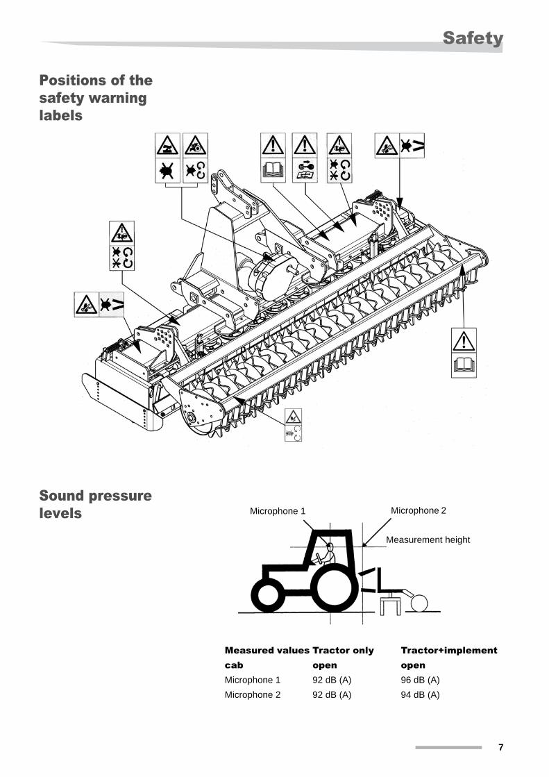
Positions of the safety warning labels
Sound pressure levels
Measured values Tractor only Tractor+implementcab open openMicrophone 1 92 dB (A) 96 dB (A)Microphone 2 92 dB (A) 94 dB (A)
Microphone 1 Microphone 2
Measurement height
8
Safety
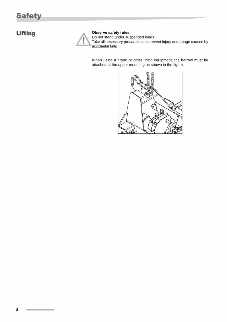
Lifting Observe safety rules!Do not stand under suspended loadsTake all necessary precautions to prevent injury or damage caused byaccidental falls
When using a crane or other lifting equipment, the harrow must beattached at the upper mounting as shown in the figure
Getting to know your machine
9
Getting to know your machineThis section contains general information on the machine andinformation on:• characteristics• Technical specifications
Intended use The NGM harrows have been constructed for the usual agriculturalapplications. Any other use is to be considered improper.
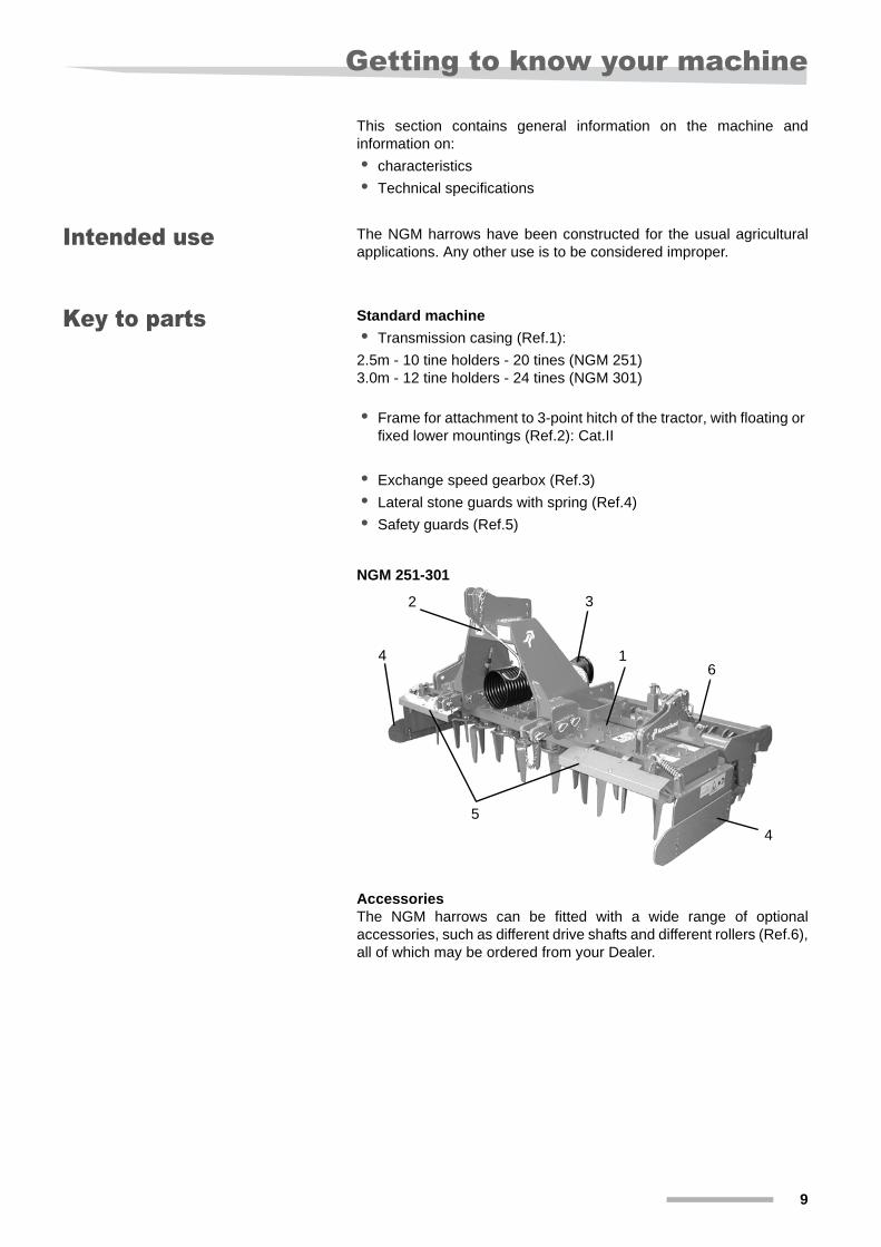
Key to parts Standard machine• Transmission casing (Ref.1):
2.5m - 10 tine holders - 20 tines (NGM 251)3.0m - 12 tine holders - 24 tines (NGM 301)
• Frame for attachment to 3-point hitch of the tractor, with floating or fixed lower mountings (Ref.2): Cat.II
• Exchange speed gearbox (Ref.3)• Lateral stone guards with spring (Ref.4)• Safety guards (Ref.5)
AccessoriesThe NGM harrows can be fitted with a wide range of optionalaccessories, such as different drive shafts and different rollers (Ref.6),all of which may be ordered from your Dealer.
NGM 251-301
1
2 3
4
4
5
6
10
Getting to know your machine
Technical specifications
Identification plate
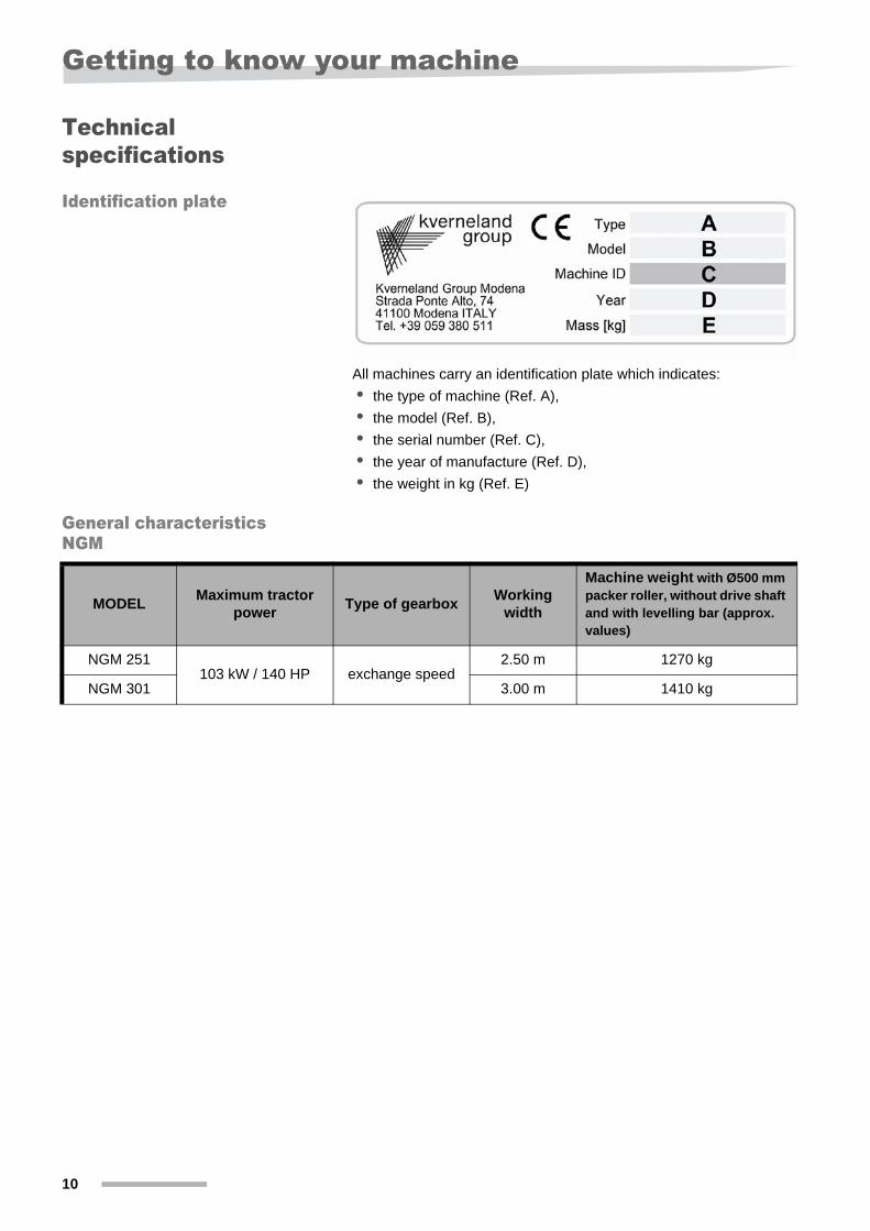
All machines carry an identification plate which indicates:• the type of machine (Ref. A),• the model (Ref. B),• the serial number (Ref. C), • the year of manufacture (Ref. D),• the weight in kg (Ref. E)
General characteristics NGM
MODEL Maximum tractor power Type of gearbox Working
width
Machine weight with Ø500 mm packer roller, without drive shaft and with levelling bar (approx. values)
NGM 251103 kW / 140 HP exchange speed
2.50 m 1270 kg
NGM 301 3.00 m 1410 kg
Delivery and preparation of the machine
11
Delivery and preparation of the machine
Checking the machine
On delivery, check that all parts of the machine are present and thatthey have not been damaged in transit; notify your dealer, importer orthe manufacturer immediately of any defects found.
NOTE For shipping purposes, some of the components may be supplied pre-assembled on the machine, while others may be fixed temporarily.
Pre-delivery checks The machine leaves the Manufacturer with all parts in fully workingorder. In all cases, it is the Retailer's responsibility to check thefollowing upon delivery to the User: • the three-point attachment is correctly mounted,• the grease in the transmission unit and the oil in the gearbox is at prescribed levels, • grease injected into the greasers is present, • all adhesive safety labels indicated in the present booklet must be
present and legible, • screws and bolts must be securely tightened, • EEC-compliant guards are provided, • the machine must be free of imperfections upon general
inspection.
The Retailer must draw the user's attention to this manual and thedrive shaft manual also provided, which must both be kept by the userthroughout the machine's service life. The Retailer is also responsiblefor recommending that the user reads these manuals carefully.
NOTE For shipping purposes, some of the components may be supplied pre- assembled on the machine, while others may be fixed temporarily.
Preparation Risk of crushing and cuts!During machine preparation operations, observe the SAFETY rules, inparticular:• make sure that the machine is in a very stable position.• Do not stand between the tractor and the machine during hitching
or unhitching operations. If it is necessary to work in the area between the tractor and the machine, observe the safety rules (tractor engine switched off, Pto disengaged, tractor parking brake applied, key removed from starter switch, chocks placed under wheels of the tractor)
• Before hitching or unhitching the machine to/from the tractor, position the lift control lever in a position where it is not possible to operate it.
• Do not stand under suspended loads• Take all necessary precautions to prevent injury or damage
caused by accidental fallsReposition and securely fix in working position all those parts of themachine that were secured in temporary positions for shipment.
12
Delivery and preparation of the machine
Positioning the roller for work
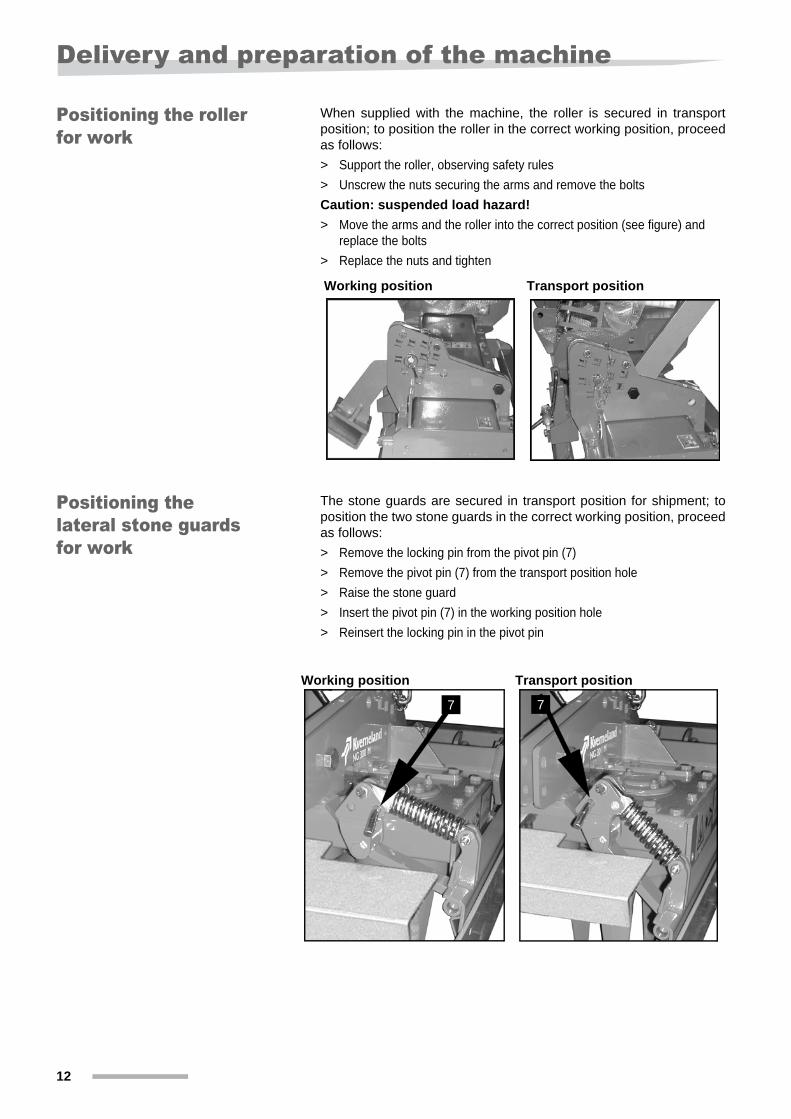
When supplied with the machine, the roller is secured in transportposition; to position the roller in the correct working position, proceedas follows:> Support the roller, observing safety rules > Unscrew the nuts securing the arms and remove the boltsCaution: suspended load hazard!> Move the arms and the roller into the correct position (see figure) and
replace the bolts> Replace the nuts and tighten
Positioning the lateral stone guards for work
The stone guards are secured in transport position for shipment; toposition the two stone guards in the correct working position, proceedas follows:> Remove the locking pin from the pivot pin (7)> Remove the pivot pin (7) from the transport position hole> Raise the stone guard> Insert the pivot pin (7) in the working position hole> Reinsert the locking pin in the pivot pin
Working position Transport position
Working position Transport position
7 7
Hitching the machine
13
Hitching the machine We strongly recommend that you observe the safety warnings given in the previous pages of this manual.
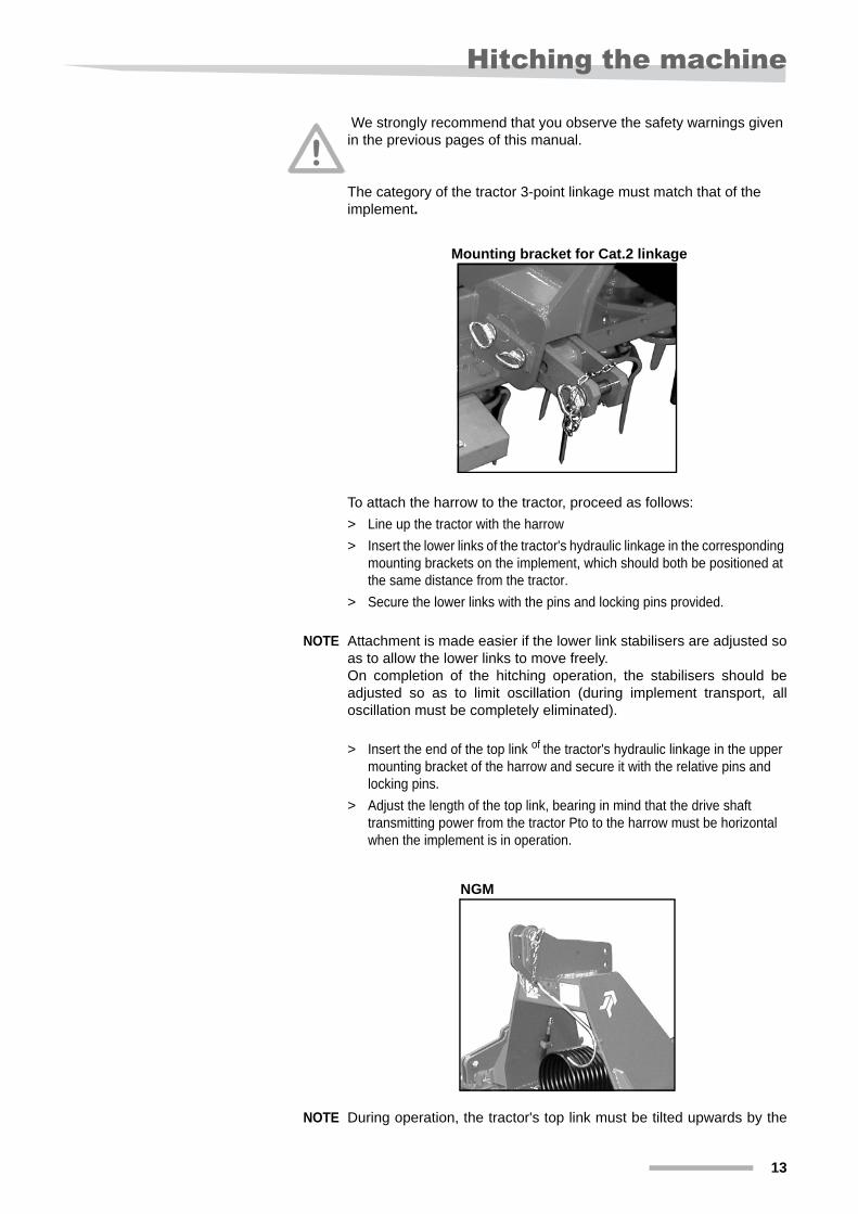
The category of the tractor 3-point linkage must match that of the implement.
To attach the harrow to the tractor, proceed as follows:> Line up the tractor with the harrow> Insert the lower links of the tractor's hydraulic linkage in the corresponding
mounting brackets on the implement, which should both be positioned at the same distance from the tractor.
> Secure the lower links with the pins and locking pins provided.
NOTE Attachment is made easier if the lower link stabilisers are adjusted soas to allow the lower links to move freely.On completion of the hitching operation, the stabilisers should beadjusted so as to limit oscillation (during implement transport, alloscillation must be completely eliminated).
> Insert the end of the top link of the tractor's hydraulic linkage in the upper mounting bracket of the harrow and secure it with the relative pins and locking pins.
> Adjust the length of the top link, bearing in mind that the drive shaft transmitting power from the tractor Pto to the harrow must be horizontal when the implement is in operation.
NOTE During operation, the tractor's top link must be tilted upwards by the
Mounting bracket for Cat.2 linkage
NGM
14
Hitching the machine
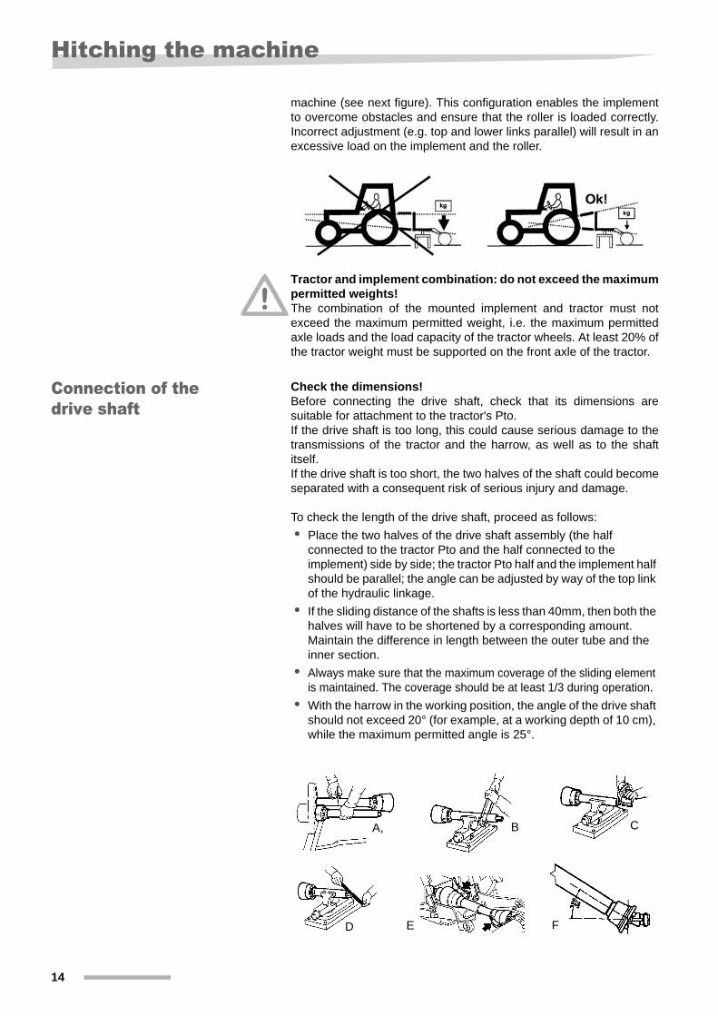
machine (see next figure). This configuration enables the implementto overcome obstacles and ensure that the roller is loaded correctly.Incorrect adjustment (e.g. top and lower links parallel) will result in anexcessive load on the implement and the roller.
Tractor and implement combination: do not exceed the maximumpermitted weights!The combination of the mounted implement and tractor must notexceed the maximum permitted weight, i.e. the maximum permittedaxle loads and the load capacity of the tractor wheels. At least 20% ofthe tractor weight must be supported on the front axle of the tractor.
Connection of the drive shaft
Check the dimensions!Before connecting the drive shaft, check that its dimensions aresuitable for attachment to the tractor's Pto.If the drive shaft is too long, this could cause serious damage to thetransmissions of the tractor and the harrow, as well as to the shaftitself.If the drive shaft is too short, the two halves of the shaft could becomeseparated with a consequent risk of serious injury and damage.
To check the length of the drive shaft, proceed as follows:• Place the two halves of the drive shaft assembly (the half
connected to the tractor Pto and the half connected to the implement) side by side; the tractor Pto half and the implement half should be parallel; the angle can be adjusted by way of the top link of the hydraulic linkage.
• If the sliding distance of the shafts is less than 40mm, then both the halves will have to be shortened by a corresponding amount. Maintain the difference in length between the outer tube and the inner section.
• Always make sure that the maximum coverage of the sliding element is maintained. The coverage should be at least 1/3 during operation.
• With the harrow in the working position, the angle of the drive shaft should not exceed 20° (for example, at a working depth of 10 cm), while the maximum permitted angle is 25°.
A, B C
D E F
Hitching the machine
15
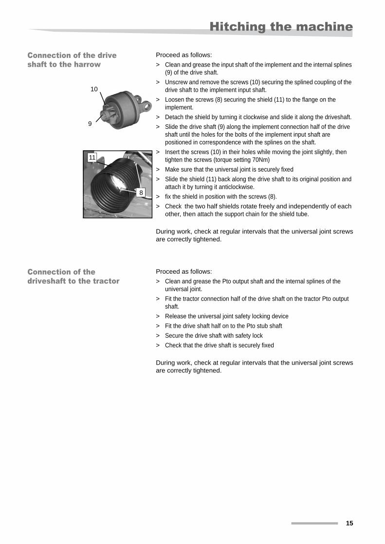
Connection of the drive shaft to the harrow
Proceed as follows:> Clean and grease the input shaft of the implement and the internal splines
(9) of the drive shaft.> Unscrew and remove the screws (10) securing the splined coupling of the
drive shaft to the implement input shaft.> Loosen the screws (8) securing the shield (11) to the flange on the
implement.> Detach the shield by turning it clockwise and slide it along the driveshaft.> Slide the drive shaft (9) along the implement connection half of the drive
shaft until the holes for the bolts of the implement input shaft are positioned in correspondence with the splines on the shaft.
> Insert the screws (10) in their holes while moving the joint slightly, then tighten the screws (torque setting 70Nm)
> Make sure that the universal joint is securely fixed > Slide the shield (11) back along the drive shaft to its original position and
attach it by turning it anticlockwise.> fix the shield in position with the screws (8).> Check the two half shields rotate freely and independently of each
other, then attach the support chain for the shield tube.
During work, check at regular intervals that the universal joint screwsare correctly tightened.
Connection of the driveshaft to the tractor
Proceed as follows:> Clean and grease the Pto output shaft and the internal splines of the
universal joint.> Fit the tractor connection half of the drive shaft on the tractor Pto output
shaft.> Release the universal joint safety locking device> Fit the drive shaft half on to the Pto stub shaft> Secure the drive shaft with safety lock> Check that the drive shaft is securely fixed
During work, check at regular intervals that the universal joint screwsare correctly tightened.
10
9
11
8
16
Preparation for work
Preparation for work
Checking the oil levels
We strongly recommend that you observe the safety warnings givenin the previous pages of this manual.Risk of burns!Beware of hot surfaces and hot oil / grease.
Before proceeding, check:• the transmission grease level• the gearbox oil level• that all the components that require greasing have been greased
(see maintenance section)
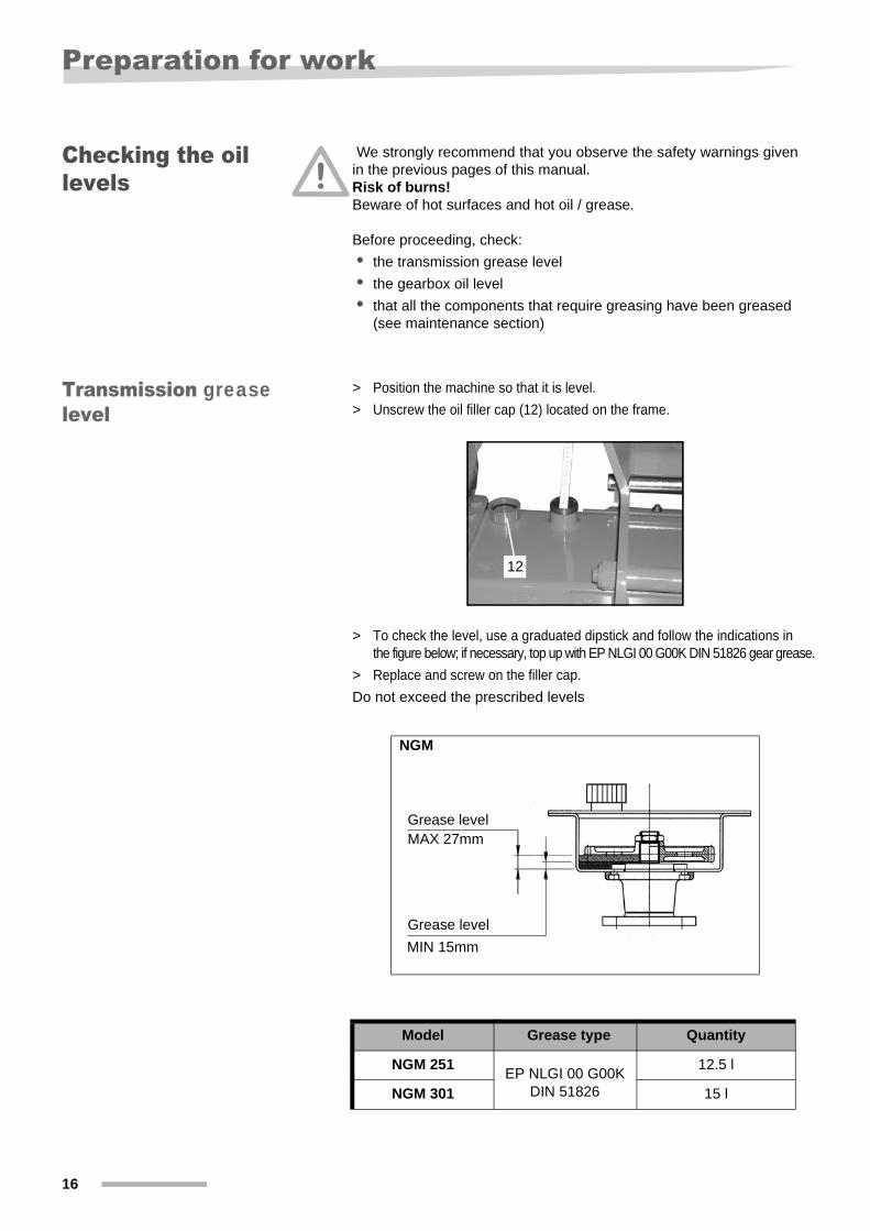
Transmission greaselevel
> Position the machine so that it is level.> Unscrew the oil filler cap (12) located on the frame.
> To check the level, use a graduated dipstick and follow the indications in the figure below; if necessary, top up with EP NLGI 00 G00K DIN 51826 gear grease.
> Replace and screw on the filler cap.Do not exceed the prescribed levels
NGM
Model Grease type Quantity
NGM 251 12.5 l
NGM 301 15 l
12
Grease level
Grease level
MAX 27mm
MIN 15mm
EP NLGI 00 G00K DIN 51826
Preparation for work
17
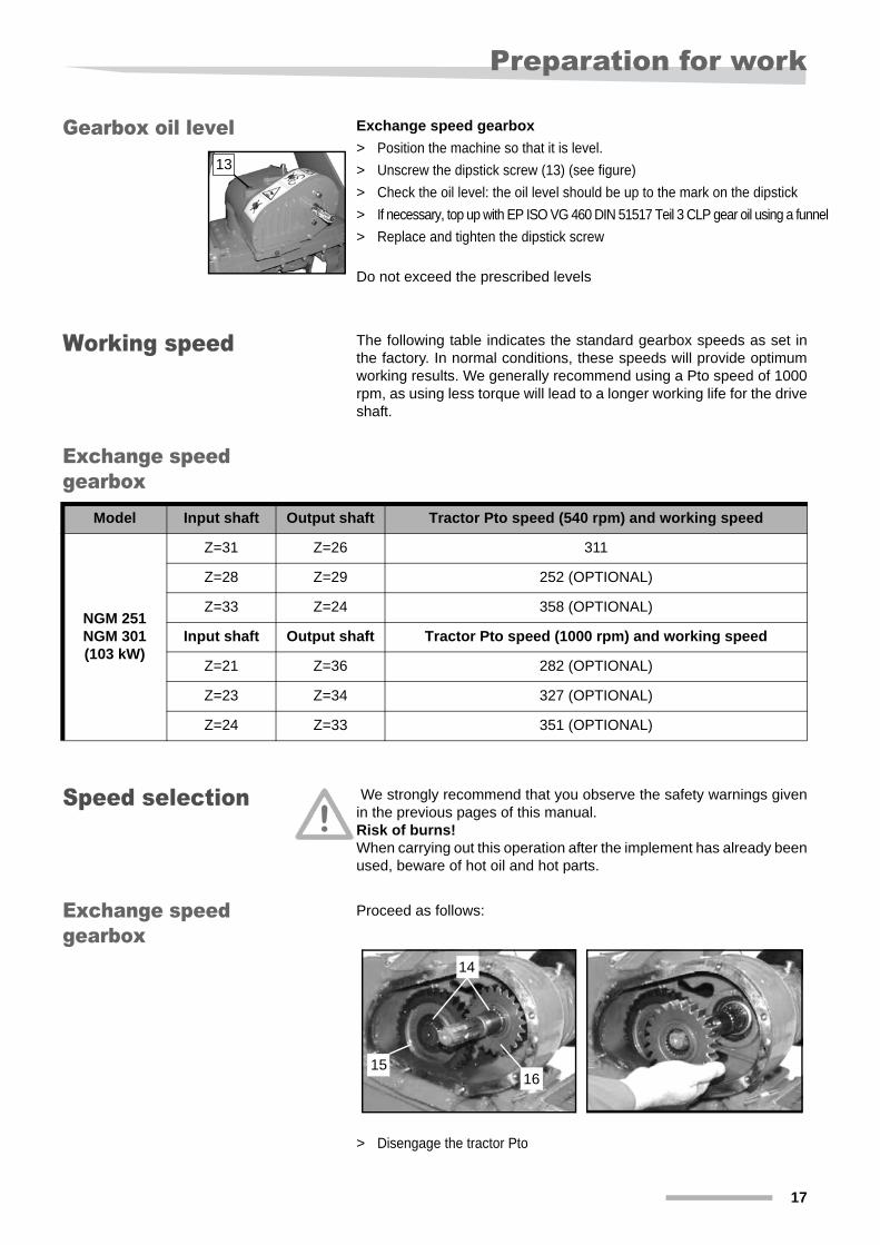
Gearbox oil level Exchange speed gearbox> Position the machine so that it is level.> Unscrew the dipstick screw (13) (see figure)> Check the oil level: the oil level should be up to the mark on the dipstick> If necessary, top up with EP ISO VG 460 DIN 51517 Teil 3 CLP gear oil using a funnel> Replace and tighten the dipstick screw
Do not exceed the prescribed levels
Working speed The following table indicates the standard gearbox speeds as set inthe factory. In normal conditions, these speeds will provide optimumworking results. We generally recommend using a Pto speed of 1000rpm, as using less torque will lead to a longer working life for the driveshaft.
Exchange speed gearbox
Speed selection We strongly recommend that you observe the safety warnings givenin the previous pages of this manual.Risk of burns!When carrying out this operation after the implement has already beenused, beware of hot oil and hot parts.
Exchange speed gearbox
Proceed as follows:
> Disengage the tractor Pto
13
Model Input shaft Output shaft Tractor Pto speed (540 rpm) and working speed
NGM 251NGM 301(103 kW)
Z=31 Z=26 311
Z=28 Z=29 252 (OPTIONAL)
Z=33 Z=24 358 (OPTIONAL)
Input shaft Output shaft Tractor Pto speed (1000 rpm) and working speed
Z=21 Z=36 282 (OPTIONAL)
Z=23 Z=34 327 (OPTIONAL)
Z=24 Z=33 351 (OPTIONAL)
14
1516

18
Preparation for work
> Wait until all moving parts have come to a complete stop> raise the implement completely or tilt it forwards to prevent oil spillage
when the gearbox cover is removed> shut off the tractor engine and remove the key from the starter switch> chock the wheels of the tractor> lock the tractor hydraulic system to prevent accidental lowering of the
linkage> Clean the gearbox casing
Warning! Risk of burns
> Remove the screws and open the rear transmission cover. Take care not to damage the gasket.
> Remove the circlips (14) and change the gears (15) and (16) according to the table above.
> Carefully install the circlips in their grooves.> Replace the gearbox cover. Check that the gasket is positioned correctly
and tighten the cover screws evenly.> Check the oil level> Apply a protective layer of lubricant to the removed gears and store them
a dry place.
Transporting the implement on the road
19
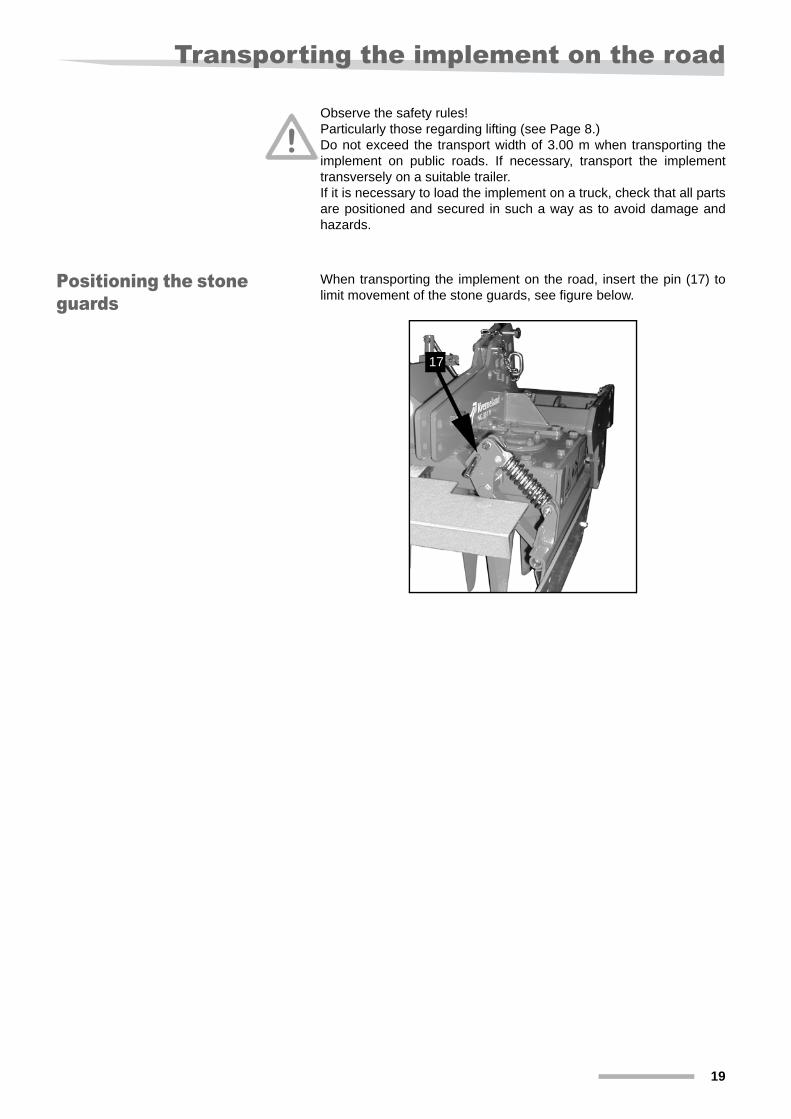
Transporting the implement on the roadObserve the safety rules!Particularly those regarding lifting (see Page 8.)Do not exceed the transport width of 3.00 m when transporting theimplement on public roads. If necessary, transport the implementtransversely on a suitable trailer.If it is necessary to load the implement on a truck, check that all partsare positioned and secured in such a way as to avoid damage andhazards.
Positioning the stone guards
When transporting the implement on the road, insert the pin (17) tolimit movement of the stone guards, see figure below.
17
20
Preparations in the field
Preparations in the field
Lateral stone guards
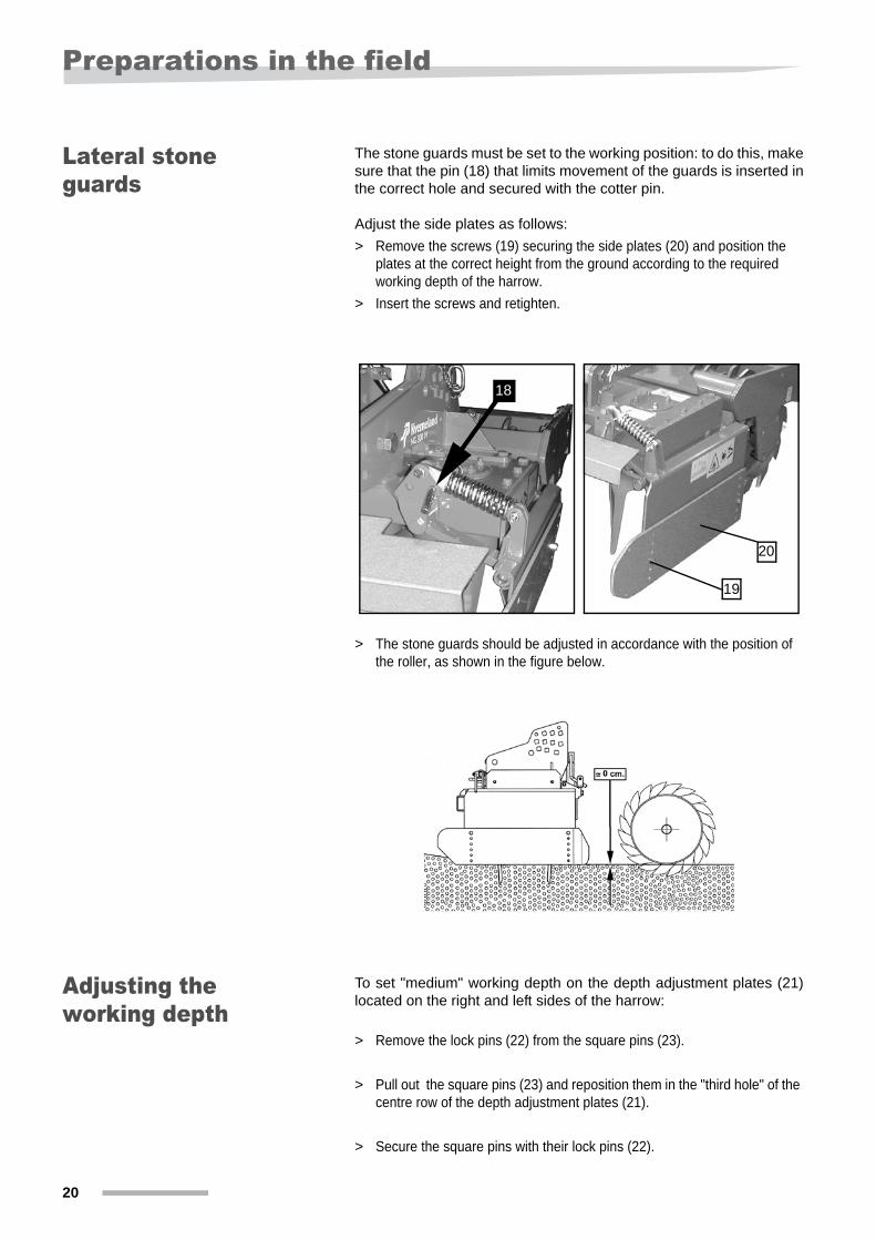
The stone guards must be set to the working position: to do this, makesure that the pin (18) that limits movement of the guards is inserted inthe correct hole and secured with the cotter pin.
Adjust the side plates as follows:> Remove the screws (19) securing the side plates (20) and position the
plates at the correct height from the ground according to the required working depth of the harrow.
> Insert the screws and retighten.
> The stone guards should be adjusted in accordance with the position of the roller, as shown in the figure below.
Adjusting the working depth
To set "medium" working depth on the depth adjustment plates (21)located on the right and left sides of the harrow:
> Remove the lock pins (22) from the square pins (23).
> Pull out the square pins (23) and reposition them in the "third hole" of the centre row of the depth adjustment plates (21).
> Secure the square pins with their lock pins (22).
18
20
19
Preparations in the field
21
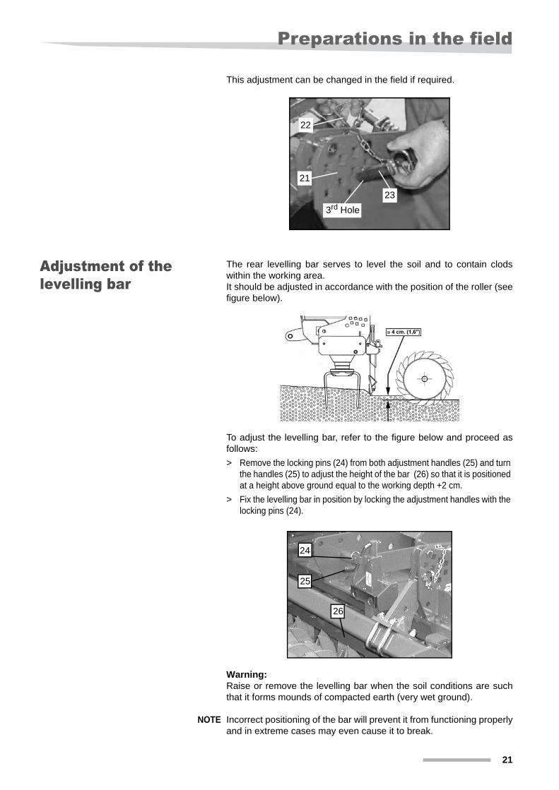
This adjustment can be changed in the field if required.
Adjustment of the levelling bar
The rear levelling bar serves to level the soil and to contain clodswithin the working area.It should be adjusted in accordance with the position of the roller (seefigure below).
To adjust the levelling bar, refer to the figure below and proceed asfollows:> Remove the locking pins (24) from both adjustment handles (25) and turn
the handles (25) to adjust the height of the bar (26) so that it is positioned at a height above ground equal to the working depth +2 cm.
> Fix the levelling bar in position by locking the adjustment handles with the locking pins (24).
Warning:Raise or remove the levelling bar when the soil conditions are suchthat it forms mounds of compacted earth (very wet ground).
NOTE Incorrect positioning of the bar will prevent it from functioning properlyand in extreme cases may even cause it to break.
3rd Hole
22
23
21
24
26
25
22
Preparations in the field
Positioning the track eradicator
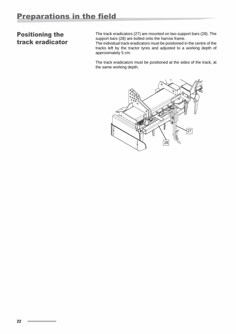
The track eradicators (27) are mounted on two support bars (28). Thesupport bars (28) are bolted onto the harrow frame.The individual track eradicators must be positioned in the centre of thetracks left by the tractor tyres and adjusted to a working depth ofapproximately 5 cm.
The track eradicators must be positioned at the sides of the track, atthe same working depth.
27
28

Cleaning, maintenance and storage
23
Cleaning, maintenance and storage
Safe storage Store the machine in a dedicated storage area away from vehicles,people or animals in transit! Do not allow children to come near or toplay on the stored machine! Park the machine so that it is stable!
Observe all applicable safety rules when unhitching the machine fromthe tractor
Winter storage To ensure that the machine is in perfect working order at the start ofthe next season:• clean the machine• apply grease where indicated• check the condition of the machine• check that all bolt, nuts and screws are fully tightened• replace any worn components• replace any damaged components• check the oil and grease levels• carry out all the necessary maintenance work• spray the machine with an anticorrosion product
NOTE Do not use a power washer in the vicinity of the breather plugs on themachine covers or on the gearbox or any other parts of the machinewhere water penetration could cause damage.
24
Maintenance
MaintenanceBefore proceeding with any maintenance work on the machine, it isessential to carry out the following operations:• never carry out any work on the machine while it is in operation• the tractor Pto must be disengaged, the engine switched off and
the key removed from the starter switch• the machine and the tractor must be secured in a stable position;
the tractor's hydraulic linkage control must be locked to prevent it being lowered accidentally.
After the first two (2) hours of operation, check the tightness of thebolts and screws; also check their tightness each day before startingwork.
We recommend that you use only original replacement parts.
Each day, before starting work, check the oil levels in the gearbox andthe grease in the transmission casing.
Lubricate the levelling bar height adjuster with multi-purpose grease(every 50 hours).
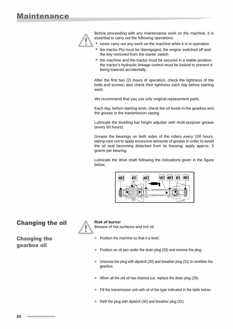
Grease the bearings on both sides of the rollers every 100 hours,taking care not to apply excessive amounts of grease in order to avoidthe oil seal becoming detached from its housing: apply approx. 3grams per bearing.
Lubricate the drive shaft following the indications given in the figurebelow.
Changing the oil Risk of burns!Beware of hot surfaces and hot oil.
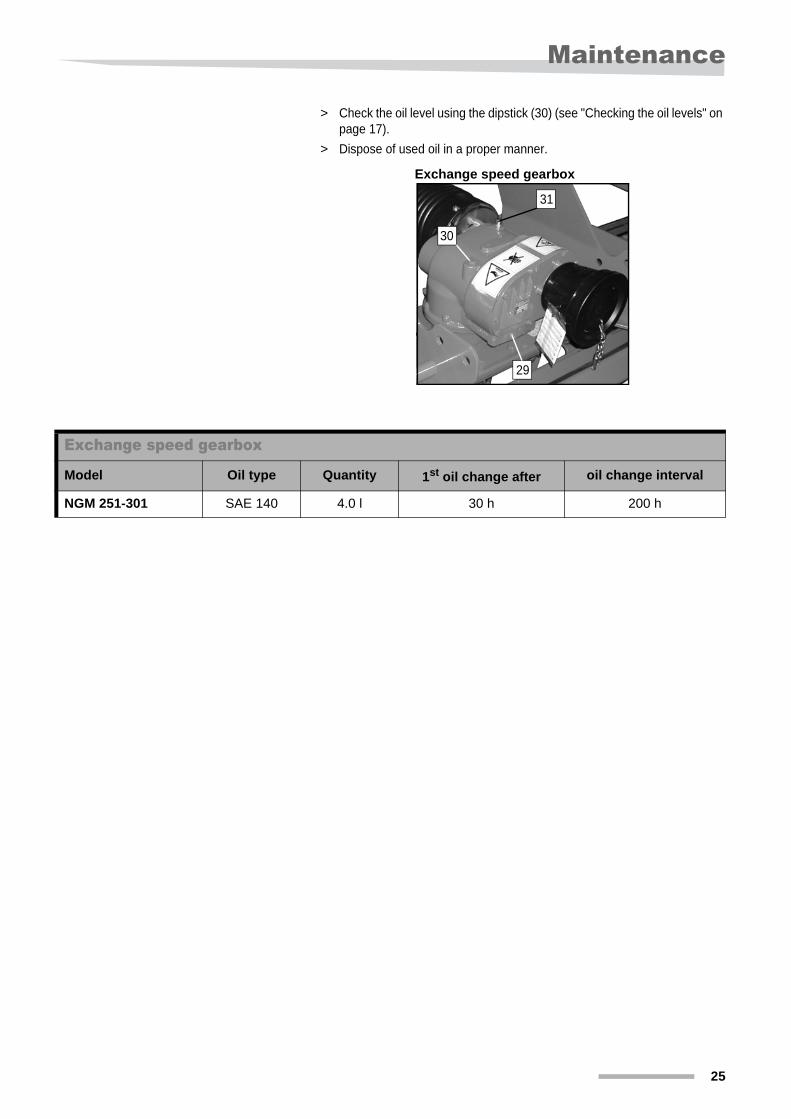
Changing the gearbox oil
> Position the machine so that it is level.
> Position an oil pan under the drain plug (29) and remove the plug.
> Unscrew the plug with dipstick (30) and breather plug (31) to ventilate the gearbox.
> When all the old oil has drained out, replace the drain plug (29).
> Fill the transmission unit with oil of the type indicated in the table below.
> Refit the plug with dipstick (30) and breather plug (31).
Maintenance
25
> Check the oil level using the dipstick (30) (see "Checking the oil levels" on page 17).
> Dispose of used oil in a proper manner.
Exchange speed gearbox
29
30
31
Exchange speed gearbox
Model Oil type Quantity 1st oil change after oil change interval
NGM 251-301 SAE 140 4.0 l 30 h 200 h
26
Maintenance
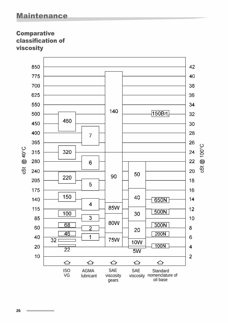
Comparative classification of viscosity
ISO AGMA SAE SAE nomenclature ofVG lubricant viscosity viscosity
gears
Standard
oil base
Maintenance
27
Replacing the tines of the harrow
We strongly recommend that you observe the safety warnings givenin the previous pages of this manual.Before proceeding, check that:• the tractor Pto is disengaged, the engine is switched off and the
key has been removed from the starter switch• that the tractor wheels are chocked• that the hydraulic linkage control has been locked to prevent the
linkage being lowered accidentally.
We recommend that you use only Kverneland original replacementparts.
NOTE The tines may continue to be used until they are worn down to halftheir original length, at which point they should be replaced. Tinesworn down to 150 mm in length (half the original length) may only beused at very shallow working depths.
Replacing the tines with bolt fastening
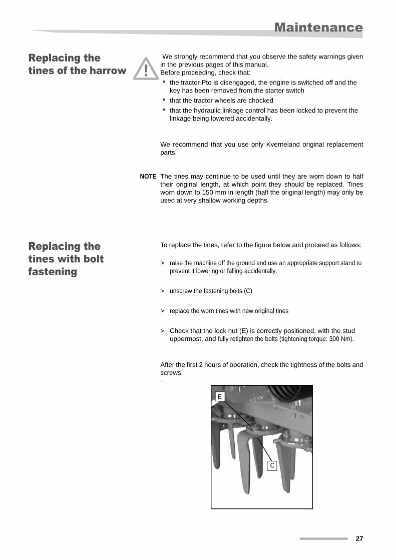
To replace the tines, refer to the figure below and proceed as follows:
> raise the machine off the ground and use an appropriate support stand to prevent it lowering or falling accidentally.
> unscrew the fastening bolts (C)
> replace the worn tines with new original tines
> Check that the lock nut (E) is correctly positioned, with the stud uppermost, and fully retighten the bolts (tightening torque: 300 Nm).
After the first 2 hours of operation, check the tightness of the bolts andscrews.· .
E
C
28
Maintenance
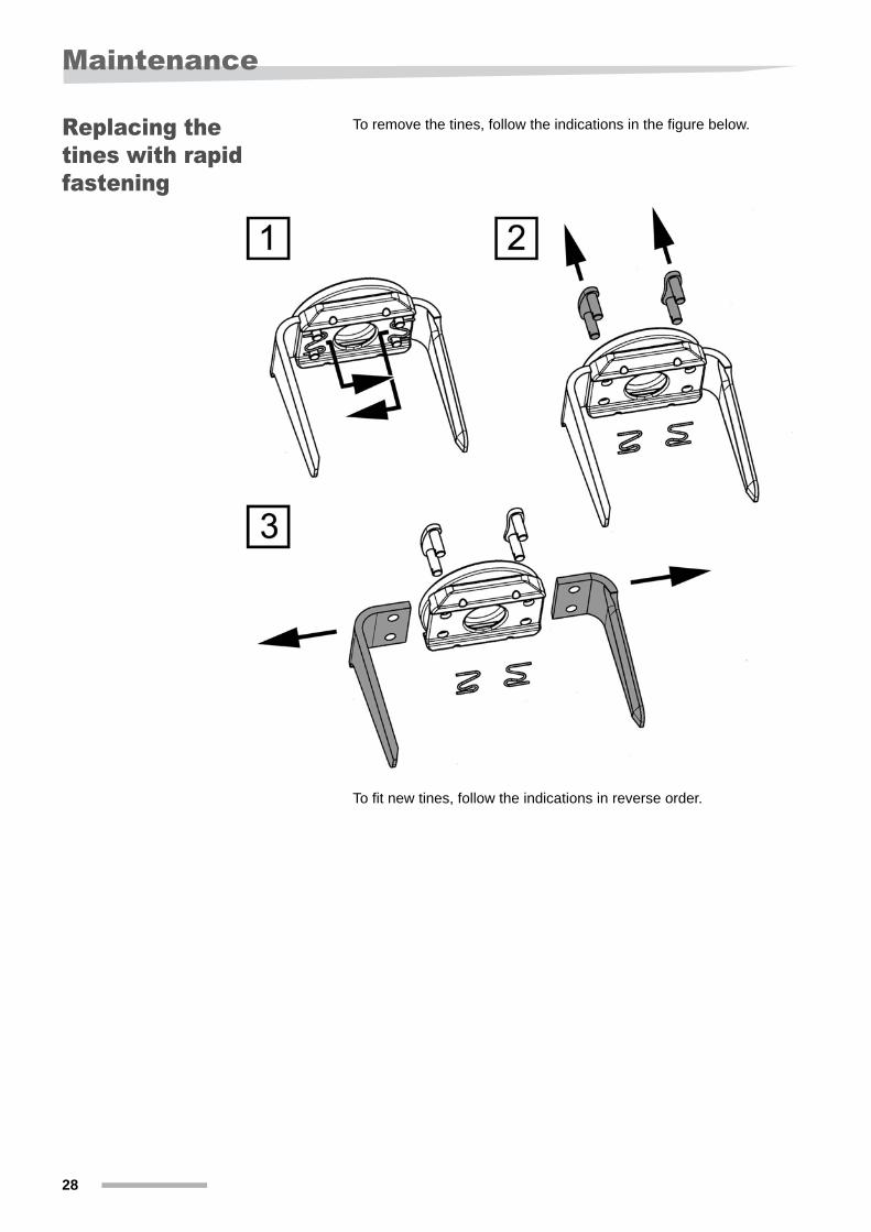
Replacing the tines with rapid fastening
To remove the tines, follow the indications in the figure below.
To fit new tines, follow the indications in reverse order.
Maintenance
29
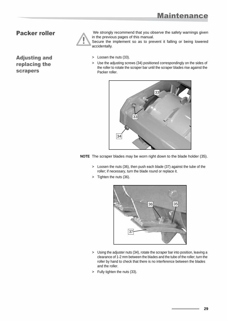
Packer roller We strongly recommend that you observe the safety warnings givenin the previous pages of this manual.Secure the implement so as to prevent it falling or being loweredaccidentally.
Adjusting and replacing the scrapers
> Loosen the nuts (33).> Use the adjusting screws (34) positioned correspondingly on the sides of
the roller to rotate the scraper bar until the scraper blades rise against the Packer roller.
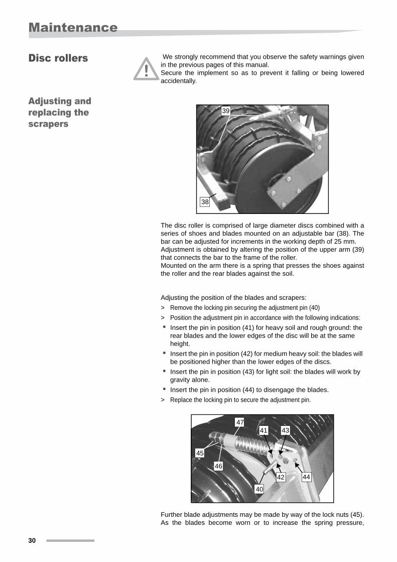
NOTE The scraper blades may be worn right down to the blade holder (35).
> Loosen the nuts (36), then push each blade (37) against the tube of the roller; if necessary, turn the blade round or replace it.
> Tighten the nuts (36).
> Using the adjuster nuts (34), rotate the scraper bar into position, leaving a clearance of 1-2 mm between the blades and the tube of the roller; turn the roller by hand to check that there is no interference between the blades and the roller.
> Fully tighten the nuts (33).
34
33
33
3536
37
30
Maintenance
Disc rollers We strongly recommend that you observe the safety warnings givenin the previous pages of this manual.Secure the implement so as to prevent it falling or being loweredaccidentally.
Adjusting and replacing the scrapers
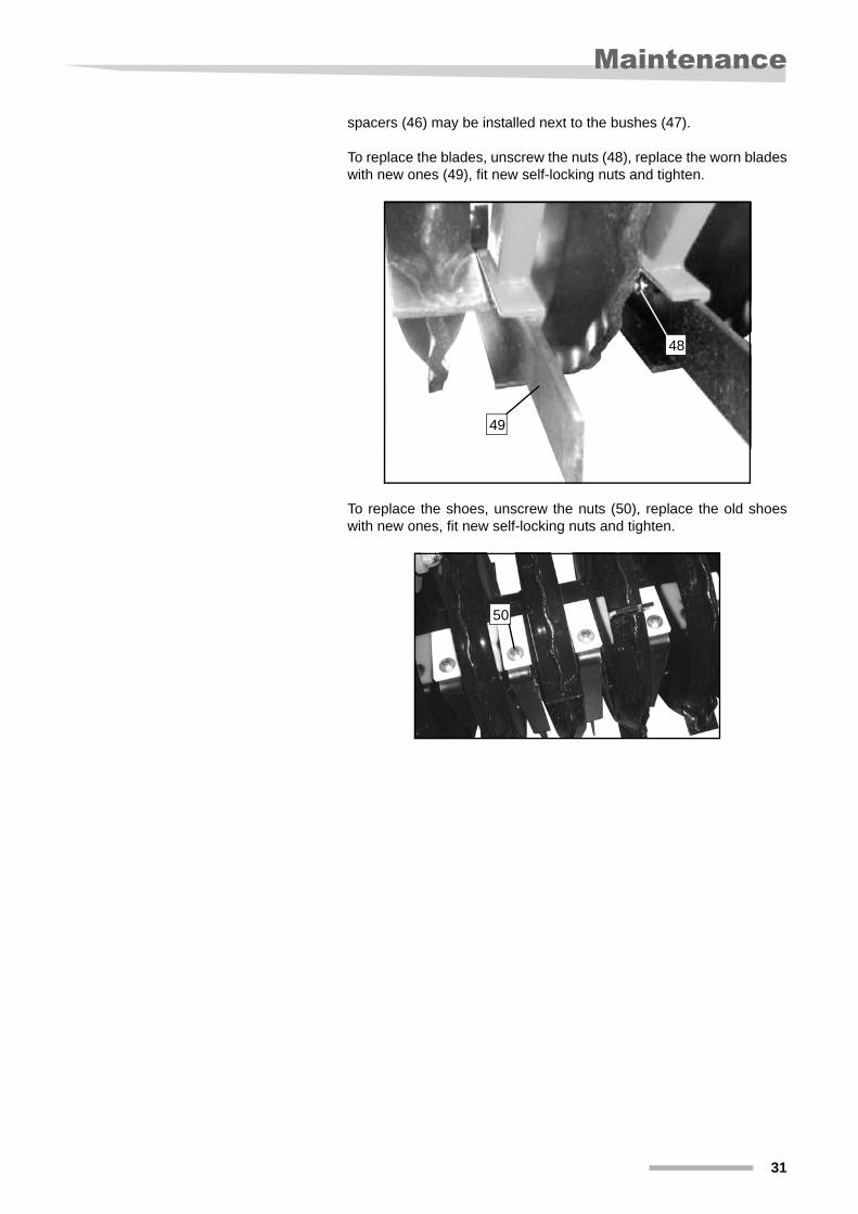
The disc roller is comprised of large diameter discs combined with aseries of shoes and blades mounted on an adjustable bar (38). Thebar can be adjusted for increments in the working depth of 25 mm. Adjustment is obtained by altering the position of the upper arm (39)that connects the bar to the frame of the roller.Mounted on the arm there is a spring that presses the shoes againstthe roller and the rear blades against the soil.
Adjusting the position of the blades and scrapers:> Remove the locking pin securing the adjustment pin (40)> Position the adjustment pin in accordance with the following indications:• Insert the pin in position (41) for heavy soil and rough ground: the
rear blades and the lower edges of the disc will be at the same height.
• Insert the pin in position (42) for medium heavy soil: the blades will be positioned higher than the lower edges of the discs.
• Insert the pin in position (43) for light soil: the blades will work by gravity alone.
• Insert the pin in position (44) to disengage the blades.> Replace the locking pin to secure the adjustment pin.
Further blade adjustments may be made by way of the lock nuts (45).As the blades become worn or to increase the spring pressure,
38
39
40
44
4341
46
45
42
47
Maintenance
31
spacers (46) may be installed next to the bushes (47).
To replace the blades, unscrew the nuts (48), replace the worn bladeswith new ones (49), fit new self-locking nuts and tighten.
To replace the shoes, unscrew the nuts (50), replace the old shoeswith new ones, fit new self-locking nuts and tighten.
48
49
50
32
Accessories
Accessories
Universal seed drill attachment
We strongly recommend that you observe the safety warnings givenin the previous pages of this manual.
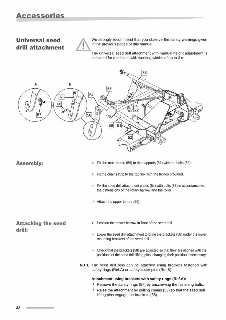
The universal seed drill attachment with manual height adjustment isindicated for machines with working widths of up to 3 m.
Assembly: > Fix the main frame (59) to the supports (51) with the bolts (52).
> Fit the chains (53) to the top link with the fixings provided.
> Fix the seed drill attachment plates (54) with bolts (55) in accordance with the dimensions of the rotary harrow and the roller.
> Attach the upper tie rod (56).
Attaching the seed drill:
> Position the power harrow in front of the seed drill.
> Lower the seed drill attachment to bring the brackets (58) under the lower mounting brackets of the seed drill.
> Check that the brackets (58) are adjusted so that they are aligned with the positions of the seed drill lifting pins, changing their position if necessary.
NOTE The seed drill pins can be attached using brackets fastened withsafety rings (Ref.A) or safety cotter pins (Ref.B)
Attachment using brackets with safety rings (Ref.A):• Remove the safety rings (57) by unscrewing the fastening bolts.• Raise the attachment by pulling chains (53) so that the seed drill
lifting pins engage the brackets (58).
56
5554
57
59 51
52
5358
61
60
Accessories
33
• Fit the rings (57) on the seed drill lifting pins and secure them in position with the screws provided.
> Attach the tie rod (56) to the upper mounting bracket of the seed drill and adjust it so that the seed drill is in the correct working position.
Attachment using brackets with safety cotter pins (Ref.B):• Disengage the safety cotter pins (60) and remove the locking pins
(61).• Raise the attachment by pulling chains (53) so that the seed drill
lifting pins engage the brackets (58).• Insert the locking pins (61) and secure them with the cotter pins
(60).
> Attach the tie rod (56) to the upper mounting bracket of the seed drill and adjust it so that the seed drill is in the correct working position.
NOTE The chains (53) should be slightly slack when the seed drill is in theworking position, so that the drill can move freely on the wheels. Theyshould not, however, be too slack as this would reduce the groundclearance when the harrow and seed drill are lifted together.
34
Accessories
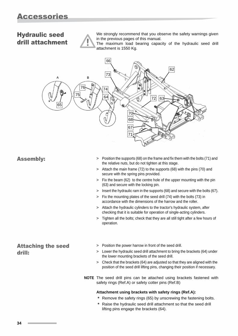
Hydraulic seed drill attachment
We strongly recommend that you observe the safety warnings givenin the previous pages of this manual.The maximum load bearing capacity of the hydraulic seed drillattachment is 1550 Kg.
Assembly: > Position the supports (68) on the frame and fix them with the bolts (71) and the relative nuts, but do not tighten at this stage.
> Attach the main frame (72) to the supports (68) with the pins (70) and secure with the spring pins provided.
> Fix the beam (62) to the centre hole of the upper mounting with the pin (63) and secure with the locking pin.
> Insert the hydraulic ram in the supports (68) and secure with the bolts (67).> Fix the mounting plates of the seed drill (74) with the bolts (73) in
accordance with the dimensions of the harrow and the roller.> Attach the hydraulic cylinders to the tractor's hydraulic system, after
checking that it is suitable for operation of single-acting cylinders.> Tighten all the bolts; check that they are all still tight after a few hours of
operation.
Attaching the seed drill:
> Position the power harrow in front of the seed drill.> Lower the hydraulic seed drill attachment to bring the brackets (64) under
the lower mounting brackets of the seed drill. > Check that the brackets (64) are adjusted so that they are aligned with the
position of the seed drill lifting pins, changing their position if necessary.
NOTE The seed drill pins can be attached using brackets fastened withsafety rings (Ref.A) or safety cotter pins (Ref.B)
Attachment using brackets with safety rings (Ref.A):• Remove the safety rings (65) by unscrewing the fastening bolts.• Raise the hydraulic seed drill attachment so that the seed drill
lifting pins engage the brackets (64).
71
67
68
64
7362
72 63
70
66
65
76 7475

Accessories
35
• Fit the rings (65) on the seed drill lifting pins and secure them in position with the screws provided.
> Attach the tie rod (66) to the upper mounting bracket of the seed drill and adjust it so that the seed drill is in the correct working position.
Attachment using brackets with safety cotter pins (Ref.B):• Disengage the safety cotter pins (75) and remove the locking pins
(76).• Raise the hydraulic seed drill attachment so that the seed drill
lifting pins engage the brackets (64).• Insert the locking pins (76) and secure them with the cotter pins
(75).
> Attach the tie rod (66) to the upper mounting bracket of the seed drill and adjust it so that the seed drill is in the correct working position.
36
Accessories
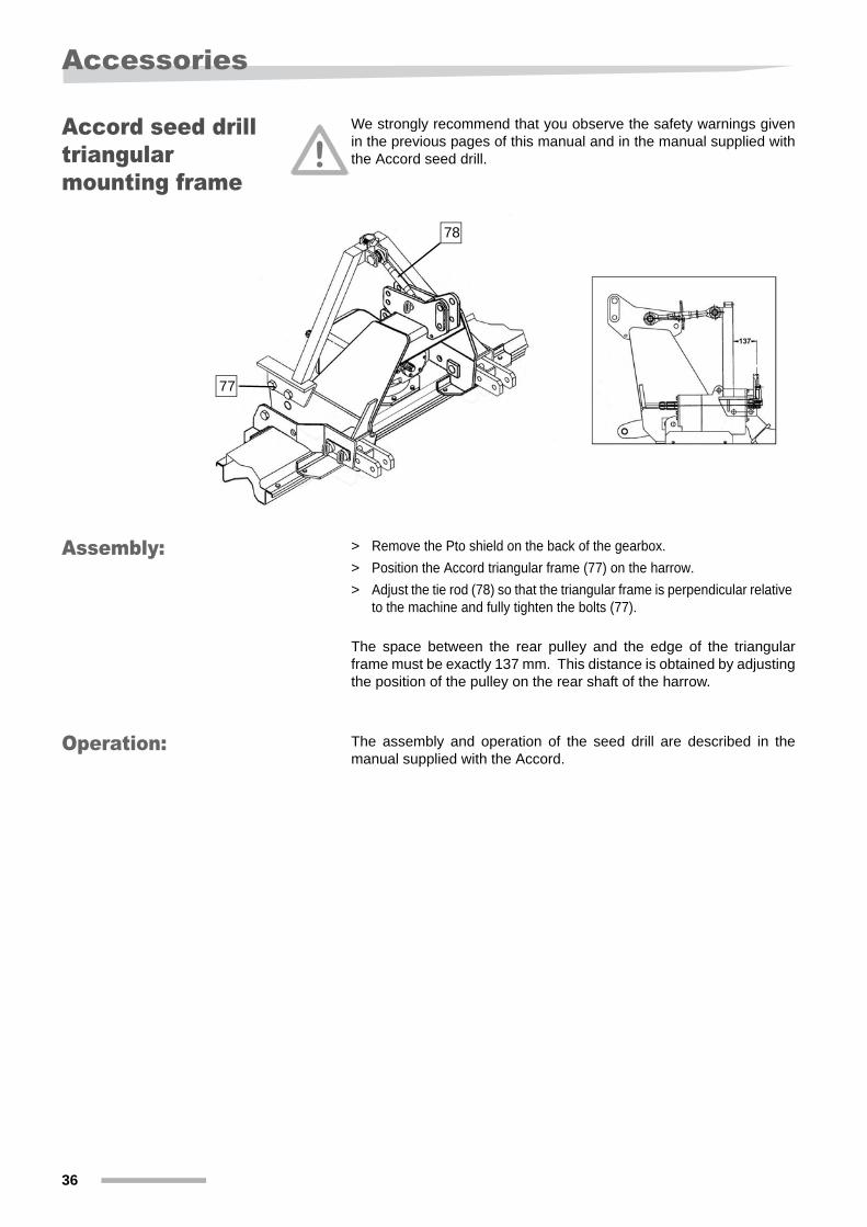
Accord seed drill triangular mounting frame
We strongly recommend that you observe the safety warnings givenin the previous pages of this manual and in the manual supplied withthe Accord seed drill.
Assembly: > Remove the Pto shield on the back of the gearbox.> Position the Accord triangular frame (77) on the harrow.> Adjust the tie rod (78) so that the triangular frame is perpendicular relative
to the machine and fully tighten the bolts (77).
The space between the rear pulley and the edge of the triangularframe must be exactly 137 mm. This distance is obtained by adjustingthe position of the pulley on the rear shaft of the harrow.
Operation: The assembly and operation of the seed drill are described in themanual supplied with the Accord.
78
77
Troubleshooting
37
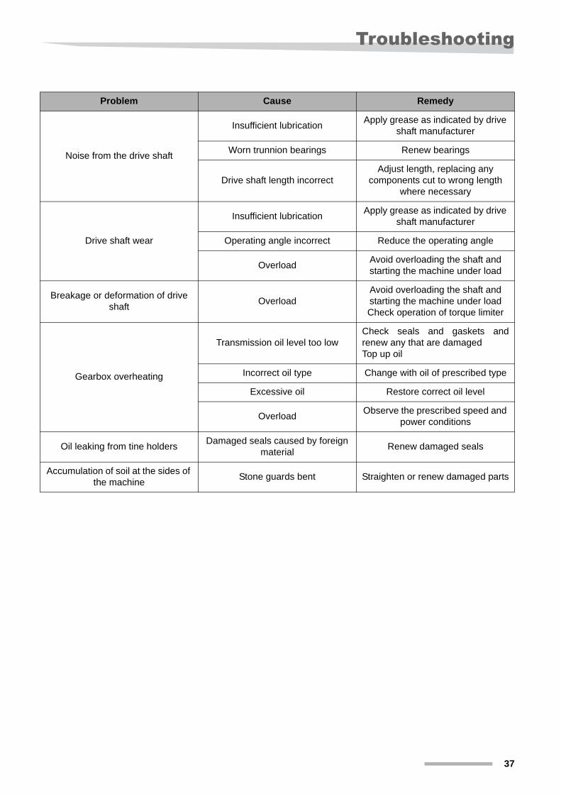
Troubleshooting
Problem Cause Remedy
Noise from the drive shaft
Insufficient lubrication Apply grease as indicated by drive shaft manufacturer
Worn trunnion bearings Renew bearings
Drive shaft length incorrectAdjust length, replacing any
components cut to wrong length where necessary
Drive shaft wear
Insufficient lubrication Apply grease as indicated by drive shaft manufacturer
Operating angle incorrect Reduce the operating angle
Overload Avoid overloading the shaft and starting the machine under load
Breakage or deformation of drive shaft Overload
Avoid overloading the shaft and starting the machine under loadCheck operation of torque limiter
Gearbox overheating
Transmission oil level too lowCheck seals and gaskets andrenew any that are damagedTop up oil
Incorrect oil type Change with oil of prescribed type
Excessive oil Restore correct oil level
Overload Observe the prescribed speed and power conditions
Oil leaking from tine holders Damaged seals caused by foreign material Renew damaged seals
Accumulation of soil at the sides of the machine Stone guards bent Straighten or renew damaged parts

38
Warranty
Warranty
Guide to warranty conditions
The machine is guaranteed for a period of 12 consecutive monthsfrom the date of delivery to the user
The warranty does not cover:1. parts subject to wear2. defects caused by modifications to the machine3. defects resulting from repairs carried out by unauthorized persons4. defects caused by repairs carried out with the use of non-originalparts5. defects caused by improper use of the machine
The manufacturer accepts no liability for any damages other than those directly affecting the machine.
Service information
Your power harrow has been completed and prepared by your dealer.All accessories have been fitted.Your dealer will provide initial information about operation of themachine and will be able to give you any further advice you mayrequire. Your dealer is also in direct contact with KVERNELANDcustomer service.Should you wish to present a claim to KVERNELAND customerservice, it is essential that you provide the following information aboutyour machine.
• Your complete address and telephone number
• Date of delivery of the machine and relative invoice number
• Type of tractor, kW - PS
• Serial number
• Date of purchase
• Date fault first occurred
• Total number of hectares worked or operating hours
• Description of conditions of use and the fault, with photographs where applicable.
This information will help us to solve the problemThank you for your cooperation!

Disposal of the machine
39
Disposal of the machineAt the end of its working life, the machine must be disposed of in aproper manner. Observe the applicable regulations governing wastedisposal.
Metal partsAll metal parts must be taken to a metals recycling centre.
Rubber partsAll rubber parts, such hydraulic and pneumatic hoses, should be takento a specialized recycling centre
PlasticsAll plastic parts should be recycled
OilUse oil must be disposed of by a specialized recycling centre
Electrical componentsShould be taken to a specialized recycling centre.
40
EC Declaration of Conformity
EC Declaration of Conformity
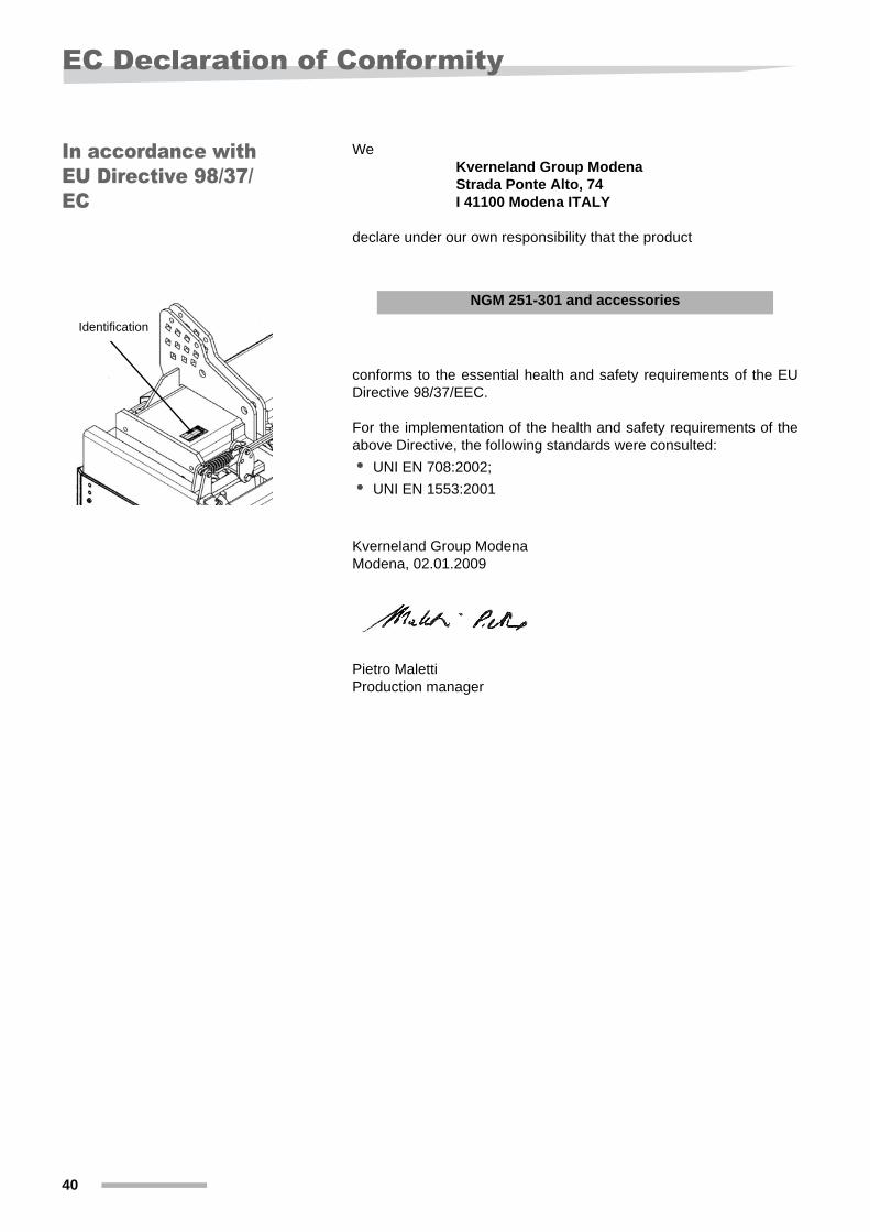
In accordance with EU Directive 98/37/EC
WeKverneland Group ModenaStrada Ponte Alto, 74I 41100 Modena ITALY
declare under our own responsibility that the product
conforms to the essential health and safety requirements of the EUDirective 98/37/EEC.
For the implementation of the health and safety requirements of theabove Directive, the following standards were consulted:• UNI EN 708:2002;• UNI EN 1553:2001
Kverneland Group ModenaModena, 02.01.2009
Pietro MalettiProduction manager
Identification
NGM 251-301 and accessories
Index
41
Index
AAccessories 32Accord seed drill attachment 36Adjusting the working depth 20Adjustment of the levelling bar 21
CChanging the gearbox oil 24Transmission grease 16Checks 11Connection of the drive shaft 15
DDisc rollers
adjusting and replacing the scrapers 30Disposal of the machine 39Drive shaft dimensions 14
EEC Declaration of Conformity 40
GGeneral characteristics 9
HHitching the machine 13Hydraulic seed drill attachment 34
IIdentification plate 10Introduction 4
KKey to parts 9
LLateral stone guards 20Lifting 8Linkage mountings 13
MMaintenance 24
NNoise emissions 7
OOil levels 16
PPacker roller
adjusting and replacing the scrapers 29Positioning the roller 12Positioning the stone guards 12Preparation for work 11
RReplacing the tines 27Rollers 29
SSafety symbols 5Speed selection 17Storage 23Symbols used 4
TTechnical specifications 10Track eradicator 22Transporting the implement on the road 19
UUniversal seed drill attachment 32
Vviscosity 26
WWarranty 38Working speed 17
Transmission grease 16