Embed Size (px)
Citation preview

Difficult Airway Management SimulatorAssessment System
User's Manual
Table of Contents
MW11
Introduction
Preparation
Before use
Training
P.1
P.9-11
Safety guidelines P.2-3
Unit contents and recommended device P.4P.5-6Assessment criteriaP.7Difficulty levelsP.7Two learning modesP.8Software icons
P.28-33
P.12-15Self-learning modeP.16Guest-learning modeP.17Using the video laryngoscope
(analog image output)
(USB image output)P.18Using the video laryngoscope
P.20Changing the assessment time limitP.19Connecting the external monitor
P.21Overview of assessment results
Replacing partsP.34-36Q&A
P.22Overview of long-term assessment resultsP.23Exporting past assessment resultsP.24Printing the assessment resultsP.25Creating a new accountP.26Editing an existing accountP.27Changing accounts
/ Turn off the power
Product Collaboration:Atsuo Takanishi Laboratory of Faculty of Science and Engineering, Waseda University

Introduction
Features●
This Di�cult Airway Management Simulator Assessment Model has been developed for the training of medical and paramedical professionals only. Any other use, or any use not in accordance with the enclosed instructions, is strongly discouraged. The manufacturer cannot be held responsible for any accident or damage resulting from such use. Please use this model carefully and refrain from subjectingto any unnecessary stress or wear. Should you have any questions on this simulator, please feel free to contact our distributor in your area or KYOTO KAGAKU at any time. (Our contact address is on the back cover of this manual)
The Di�cult Airway Management Simulator Assessment System is the world exclusive system that o�ers objective feedback on intubation skills carried out by "hands-on" with the true-to-life airwaymanikin and real instruments. Real time visualization of performance on each evaluation point helps to assess trainees' skill as well as to identify the area where trainees need further improvement.
Objective feed-back is given at two levels:-Intubation Result: higher possibility of saving patient's lives-Skills Assessment: lower negative impact on patients
Manufacturer s note’
Each session can be saved and stored for review and debrie�ng.
Feedback on assessment criteria is quantitatively monitored and displayed.-Sni�ng position, Force on incisor, Blade position, Force on tongue, Lift epiglottis, Tube positioningand Cu� pressure
A variety of di�cult airway can be set by touch panel control.
All-in-one unit is convenient for training.
● Training SkillsTracheal intubationIntubation and ventilation on di�cult airways
Safety guidelines
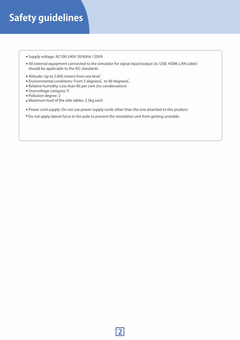
Supply voltage: AC100-240V 50/60Hz 120VA
All external equipment connected to the simulator for signal input/output (ie. USB, HDMI, LAN cable) should be applicable to the IEC standards.
Altitude: Up to 2.000 meters from sea-levelEnvironmental conditions: From 5 degreesC. to 40 degreesC.Relative humidity: Less than 80 per cent (no condensation)Overvoltage category:ⅡPollution degree: 2Maximum load of the side tables: 2.5kg each
Power cord supply: Do not use power supply cords other than the one attached to this product.
Do not apply lateral force to the pole to prevent the simulation unit from getting unstable.
●
●
●
●
●
●
●
●
●
●

Safety guidelines
3
DOs and DONʼTsDOs DONʼTs●Operate the system under the designated circumstances
●Do not disassemble or open electric or precision components
Power input: AC100V~230V plus or minus 10%, 50Hz/60Hz Temperature range: between 0 degrees C and 40 degrees C (no congelation)Relative humidity; between 0%to 80% (no condensation)*Connecting to power source outside of the designated range may lead to fire.
●Safe disposition
●Handle with care
●When the electric parts get warm or produce smoke, immediately turn off the power and unplug from the power source
●Storage
●Handle the power plug and cord observing following precautions
●Never wipe the product and components with thinner or organic solvant
Don’t mark on the product and components with pen or leave any printed materials in contact with their surface.
The electric components are precision instruments.Strong shocks or continuous vibration may cause breakages of its internal structure.
Take at least 30 minutes shutdown, turning off the power, every 2 hours.
Risk of shock.
Do not pour or spill water or liquid detergent over the electric components, power cable and power plug.Running the system while the electric components are wet may create a shock hazard or a risk of fire.
Do not put the product close to fire. It may lead to discolor-ation or deformation of the product as well as short circuit, creating a risk of fire.
This simulator is not designed for tracheotomy training. Do not apply excessive force or pressure onto the simulator.
●Do not give shocks
●Do not wet the electric components
●Do not handle the power plug with wet hands
●No fire
●Do not use the manikin for tracheotomy.
It may lead to system malfunctions.
●Do not install other software onto the computer
●Do not run the system continuously over 2 hours
●Ink marks on the soft surface wonʼt be removable
To avoid short circuit, do not run the simulator set above a power receptacle.
Risk of fire. Contact your distributor or the manufacturer for repair.
The materials for the models are special compositions of soft resin. Please handle them with utmost care at all times.Clean the manikin with water or mild detergent and coat with baby powder. Be careful not to apply water or detergent on the internal machinery.Hold the handle when moving the simulator. It is dangerous to move the simulator by holding manikin the monitor, its pole or the manikin. Be sure to lift the unit at least 2 people if transfering from one level to another.
Store the simulator at room temperature, away from heat, moisture and direct sunlight.Storage under the temperature above 50 degrees C may reduce the performance quality of the simulator.
●Follow the instructed shutting down procedures
Shut down your computer first. Do not turn off the power or unplug the power cord without shutting down the program. Misuse may lead to damages.
Discoloration of the surface may occur after used after a long period of time. Discoloration does not affect the function of the simulator.
1. Clean the head of the plug periodically.2. Plug in the plug to the outlet firmly to the end.3. Always hold the plug when unplugging. Do not pull the cable.4. Do not force to bend, twist the cable and avoid scratching or cutting on it.5. Unplug the power cord when the simulator is not in use.6. Remove any dust that has accumulateed on the power plug and insert the plug completely into the power socket.Failing to follow the above precautions can result in damage in the plug and the cable, constituting risk of fire or shock.
Do not open up or disassemble the housing for electric parts or precision components.Refrain from opening up any lids, caps or covers for such area, and never run the system while any of such covers are open.*Never disassembling the electric components, power plug and cable as it may create a risk of fire, shock or injury. Contact your distributor or the manufacturer for repair.
Before use Unit contentsRecommended devices
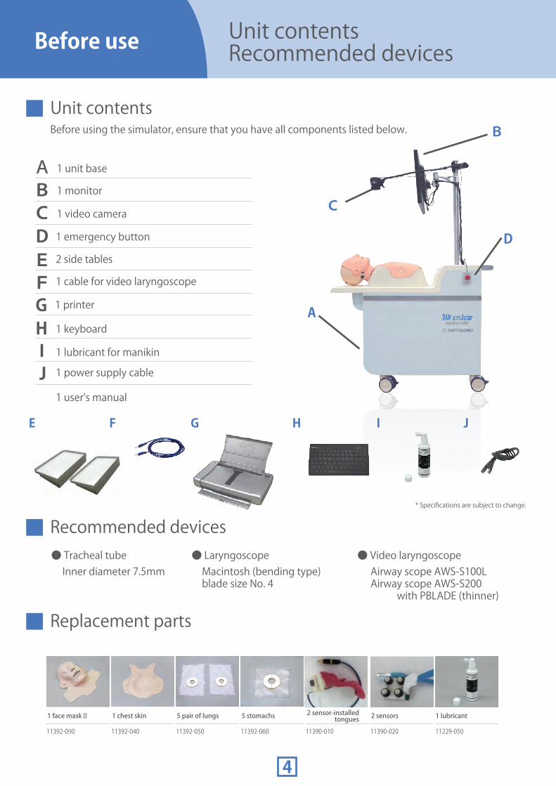
Unit contentsBefore using the simulator, ensure that you have all components listed below.
● LaryngoscopeInner diameter 7.5mm Macintosh (bending type)
blade size No. 4Airway scope AWS-S100LAirway scope AWS-S200 with PBLADE (thinner)
● Video laryngoscope● Tracheal tube
1 unit base
1 monitor
1 video camera
Replacement parts
Recommended devices
A
B
D
A
BCC
F HE G
1 printer
2 side tables
1 cable for video laryngoscope
1 lubricant for manikin
DEF
HI
1 user's manual
1 emergency button
1 keyboard
G
2 sensors
11390-020
1 lubricant
11229-050
2 sensor-installed tongues
11390-010
5 stomachs
11392-060
5 pair of lungs
11392-050
1 chest skin
11392-040
1 face maskⅡ
11392-090
I
1 power supply cable
* Specifications are subject to change.
J
J

Before use Assessment criteria
MW11 Difficult Airway Management Simulator Assessment System provide objective assessment and analysis of the user's performance.
Intubation result on the left of the screen is the Successful/Failure assessment with criteria and , and on the right of the screen is the skills assessment with criteria to . The skills assessment focuses on the negative impact given to the patient during the procedure.
Blade Position
normal
laryngoscope
name
★☆☆☆
SUCCESS
X: 16° Y:32° 180 N
Grade 2 Good 7.9 cc
Before use Assessment criteria
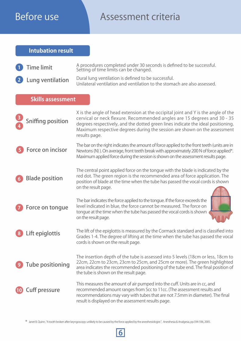
Time limit A procedures completed under 30 seconds is defined to be successful.Setting of time limits can be changed.
X is the angle of head extension at the occipital joint and Y is the angle of the cervical or neck flexure. Recommended angles are 15 degrees and 30 - 35 degrees respectively, and the dotted green lines indicate the ideal positioning. Maximum respective degrees during the session are shown on the assessment results page.
The bar on the right indicates the amount of force applied to the front teeth (units are in Newtons (N) ). On average, front teeth break with approximately 200 N of force applied*. Maximum applied force during the session is shown on the assessment results page.
* Janet B. Quinn, “A tooth broken after laryngoscopy: unlikely to be caused by the force applied by the anesthesiologist.", Anesthesia & Analgesia, pp.594-596, 2005.
The central point applied force on the tongue with the blade is indicated by the red dot. The green region is the recommended area of force application. The position of blade at the time when the tube has passed the vocal cords is shown on the result page.
The bar indicates the force applied to the tongue. If the force exceeds the level indicated in blue, the force cannot be measured. The force on tongue at the time when the tube has passed the vocal cords is shown on the result page.
The lift of the epiglottis is measured by the Cormack standard and is classified into Grades 1-4. The degree of lifting at the time when the tube has passed the vocal cords is shown on the result page.
The insertion depth of the tube is assessed into 5 levels (18cm or less, 18cm to 22cm, 22cm to 23cm, 23cm to 25cm, and 25cm or more). The green highlighted area indicates the recommended positioning of the tube end. The final position of the tube is shown on the result page.
This measures the amount of air pumped into the cuff. Units are in cc, and recommended amount ranges from 5cc to 11cc. (The assessment results and recommendations may vary with tubes that are not 7.5mm in diameter). The final result is displayed on the assessment results page.
Dural lung ventilation is defined to be successful.Unilateral ventilation and ventilation to the stomach are also assessed.Lung ventilation
Sniffing position
Force on incisor
Blade position
Force on tongue
Lift epiglottis
Tube positioning
Cuff pressure
Intubation result
Skills assessment

Successful lung ventilation in both lungs will receive a passing assessment.Sensors will also be able to detect ventilation to just one lung or to the stomach.
Self-learning Mode
Guest-learning Mode
Before use Difficulty levels
Before use Two learning modes
Simulation of patient with no airway difficulties. Opening the mouth and retroflexion of the neck is most easy out of all four levels.
Simulation of patient with locked jaw. Opening the mouth is more difficult.
Simulation of patient with limitations in neck retroflexion. Users face difficulty when trying to raise the chin.
Simulation of patient with micrognathism (recess of lower jaw). Opening the mouth as well as retroflexion of neck are more difficult.
Definitions of each difficulty level
Login with a user account to save training data.
Login as a guest user to take the assessment and see the results. Results cannot be saved in the Guest-learning mode. This mode is useful for seminars.
When creating an individual user account, following information is required:●User ID ●Name ●Password ●Name of Department/Organization●Grade in School ●Years of Experience
Normal(Difficulty level ★)
Lock Jaw(Difficulty level ★★)
Rigid Neck(Difficulty level ★★★)
Micrognathia(Difficulty level ★★★★)

Before use Software icons
Help icon guides you through the help menu during your simulation procedure.
Following icons are on the top right corner of your screen.
Tap on the “Help” icon
Home Data Accounts
Print Help Power
Tap on the “Help” icon on the top right corner.
Return to the main scenario selection menu
Display all assessment results data from the past
Manage your accounts
Print your assessment results page
Open the help menu Log out of an account orshut down the system
1
Help menu displayOnce the help menu is displayed, tap on the topic of interest. To close the help menu, tap on the X button on the top right corner.
2

Help Icon will guide you through the help menu during your simulation procedure.
Preparation
Lock the wheels before using the simulation unit to prevent the unit from moving.
Move the simulation unit to the designated location and push down on the black tab on each wheel. Do this to all four wheels to secure the unit in place.
Locking the wheels
Attach side tables on the simulation unit for additional equipment space.
Lift and handle the side tables with both hands to prevent injuries or damages.
Insert the side tables onto the bar along the simulation unit. Refer to the images on the right for more details.
If the side tables are not in use, store the side tables in the drawer of the simulation unit.
Attaching the side tables

1
2
The simulation unit does not work properly if the emergency button is pushed down. Verify that the emergency button is set up correctly.
Setting up accessories for the simulation unit
The keyboard is used to set up account information.
Turn on the power switch on the back of the keyboard. The keyboard is wirelessly connected to the PC.
Turn on the printer with the power switch on the top. The printer is used to print out the result screen.
Setting up the keyboard
Setting up the emergency button
Setting up the printer
Released- Emergency button not activated
Verify that the emergency button is not pressed down.
If the button is pressed down, turn the button clockwise to release the lock.
○ × Pressed down- Emergency button activated
Preparation

Setting up the simulation unit
Connect the power cord to the socket on the rear side of the simulation unit.
Connecting the power cord 1
Push the power switch next to the power socket to the [-] sign. The light of the simulation unit poser button on the top edge of the table will blink dimly.
Turning on the power 2
Push the simulation unit power button on the top edge of the table. The button will blink light up green when it is turned on. The software will automatically turn on with the simulation unit. Wait for the login screen to appear on the monitor.
Turning on the simulation unit3
Do not press the power button of the touch-screen monitor.
Trouble shooting P. 34
Preparation
The touch-screen monitor will automatically power on when the simulator power switch is turned on. If the monitor does not turn on after the simulator power switch has been turned on, please check the monitor power button.

Training Self-learning mode
Please use the pen attached to the right bottom corner of the monitor to operate the touch-screen feature. Touch-screen monitors can also be operated with the fingers.
When the login screen is displayed, enter the user ID and password, and tap on the Login button.
To login as a guest P. 16To create a new account P. 25
Login1
Select the case and equipment you are using 2
Select the case.
Select equipment.
To use video laryngoscope P. 17, 18
Select a case scenario and an equipment from the buttons on the left half of the window. Then adjust the head of the manikin so that it lies parallel to the simulator table. When the head is positioned correctly, the indicator on the right side shows “OK” (see below). In case the manikin neck is rigid, press the button under the “Incorrect” indicator to release. Then retry positioning till the indicator confirms “OK” .Press “Next” to proceed.
In case of using video laryngoscope with USB output video, first turn on the video laryngoscope and connect the USB cable and press the “Next” button on this screen.

Self-learning mode
Initial positioning of manikin head3Initial position and scenario are set automatically. Do not touch the manikin until the indicator gauge reaches 100% and the display transits to a new screen.
Do not touch the manikin while the bar is loading.
Training
Abnormal operation of the chin P. 35
Manual setting of manikin headInitial position of manikin head can be set manually when the automatic initialization is failed.
Adjust the head of manikin until all 3 indicators show “OK”Once the manikin has been positioned correctly, “Next” button appears. Press “Next” to proceed.
4
.
Incorrect

Self-learning mode
Beginning the assessment4When the positioning is completed, the below image appears on the screen.
Tap on the “Start” button to begin the session. The video recording and sensor data recording will also begin.
Adjust the camera to capture your hand motions for video recording so that image of the trainee and the manikin head is displayed on the left side of the screen.
When intubation is completed and air inflow is verified at lungs, the assessment will automatically stop and the assessment results page will appear. The session can also be finished manually by tapping on the “Stop” button.
Details on assessment criteria P. 5-6
Trouble shooting P. 35
start back
In order to measure the cuff pressure correctly, release all air from the cuff before procedure implementation.
Spray lubricant to intraoral, tube and blade before procedure implementation.
Training
Blade Position
normal
laryngoscope
name
X: 16° Y:32° 180 N
Grade 2 Good 7.9 cc

★☆☆☆
Blade Position
normal
laryngoscope
name
Grade 3 Good 7.9 cc
185NX: 16° Y:32°
Details on assessment criteria P. 5-6
Session finishes automatically when the procedure lasts certain length of time. P. 35
Before moving onto next session, release all air from the cuff and spray lubricant to intraoral, tube and blade.
Self-learning mode
Assessment results5The results page will appear once the assessment is completed. The results page displays intubation result of successful or failure, as well as the multidimensional skills assessment.
“Success” procedure is defined as the procedure that completes under 30 seconds. Procedures that exceed the time limit will be a "Failure". Time limits can be adjusted.
The skills assessment evaluates the amount of stress applied to the patient during the procedure. Assessment components include the sniffing position, pressure on front teeth, positioning of blade, force on the tongue, lifting of the epiglottis, depth of the tube and cuff pressure.
Successor Not
SkillsAssessment
Training
SUCCESS

Training Guest-learning mode
Train as a guest
Assessment record of guest users cannot be saved.
Go to the Login page and check the “Login as Guest” option. The ID and Password can remain blank. Tap on the Login button.
After logging in, the guest user can select a difficulty level, a case scenario and an equipment and start the session in the same way as an individual account user.
Guest users cannot save their assessment results. To save assessment records, create an individual user account before starting the session.
Check the “Login as Guest” option.
Create a new account P.25
Self-learning mode P. 12

Using the video laryngoscope(analog image output)
To use the video laryngoscope (analog image output) for assessment, the equipment must be connected to the simulator before beginning the session.
■Pentax Airway Scope - AWS S100LRecommended device
Use a video laryngoscope(analog image output) with a mini plug compatibility.
Prepare the included cable for the video laryngoscope.
Insert one end of the cord into the port near the simulator power switch, and connect to the video laryngoscope.
1
2
Then select the video laryngoscope on the screen. When you proceed to the assessment page, tap on the camera 2 tab to see the image captured by the video laryngoscope.
The simulator uses mini-plug to connect with a video laryngoscope. Be sure to use a device that is compatible with the mini-plug.
3カメラ 21
Training
camera1 camera2

Using the video laryngoscope(USB image output)
In case of using the video laryngoscope (USB image output) for the training session, turn on the video laryngoscope and connect it to the simulator before selecting the devices to be used.
Recommended the blade for AWS S200:PBLADE (THINNER)
Prepare the USB cable attached to the video laryngoscope
Connect one of the plugs in the USB port near the simulator’ s switch, and the other one in the video laryngoscope.
1
2
After connecting the plugs, turn on the video laryngoscope and select “AWS S200” . Once entering into the training page, select the tab “Camera 2” displayed on the video reproduction window. The images from the laryngoscope will be displayed on the screen.
3
Training
Connecting the external monitor
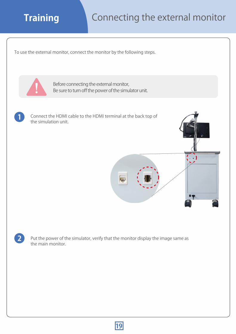
To use the external monitor, connect the monitor by the following steps.
Before connecting the external monitor,Be sure to turn off the power of the simulator unit.
Connect the HDMI cable to the HDMI terminal at the back top of the simulation unit.
Put the power of the simulator, verify that the monitor display the image same as the main monitor.
1
2
19
Training

Changing the assessmenttime limit
Open the Login page
How to change the time limit (default is 30 seconds.)
Tap on the Power Icon on the top right corner and log out.
1
Open the Settings page
Check the Setting option. Then ID will automatically fill in.Enter in " " as the password.Tap on the Login button.
admini
2
Change the time limit
In the settings page, select the difficulty level on the top left corner, as well as the case scenario. The time limit for the chosen scenario can be changed on the lower right section of the screen. Tap on the “Configuration” button to save the change.
3
20
① Select case scenario ② Change time limit
③ Save
Training

Overview of assessment result
Displaying the 5 most recent assessment results
Tap on the “Performance” tab on the assessment results page. For each respective case scenario, the total number of assessments completed, the number of passing assessments completed, results of the 5 most recent assessments and the success rate of last 5 trials will display.
On each assessment result display, recorded video of the training session can be replayed by tapping on the review button.
Details of each of last 5 assessment can display by clicking the tabs.
21
③ Change time limit
Training
Laryngoscope

Blade Position
normal
laryngoscope
name
X:16° Y: 32° 180 N
7.9 ccGrade 2 Good
Overview of long term assessment results
To see an overview of past assessment results of longer period, tap on the Data Icon on the top right corner.
List of the past assessment result is shown.Each assessment result can be opened in sheet format by selecting the line and tapping on the “Sheet” button.
22
1
2
Training

Exporting past assessment results
Connect the USB drive
Display the assessment data
Select the data to export
Export
Tap on the Data Icon to display the assessment data.
Select the data to export and tap on the Export button.
Select your USB drive on the computer and save the data. The assessment video file, sensor file and an image of the assessment results page are saved.
Insert a USB drive to the USB port beneath the simulation unit power button.
Assessment data can be exported onto USB drives.
1
4
3
2
Training
23

Print the assessment results
Use the included printer to print your assessment results.
Open the assessment results data to print and tap on the Print icon on the top right corner.
1
Press OK to print. 2Do you print this screen?
24
Training

Create the new account
Open the “Creating an account” page
An individual user account needs to be created to save assessment data.
Tap on the Create an account link on the Login screen.
1
Account information
Input the following information for the new account.
●User ID ●Name ●Password●Name of Department/Organization●Grade in School ●Years of Experience
When all information is completed, tap on the Confirm button on the bottom right corner.
*Enter your password twice for confirmation.*Enter N/A for inapplicable fields
2
Verification of account information
Verify your account information and tap on the “Save” button to submit. Tap on the “Change” button to edit your account information.
3
Training
25

Training Editing an existing account
Open the account information page
How to edit your account information
Tap on the “Accounts” icon on the top rightcorner to open the account information page.
1
Open the account editing page
Tap on the “Change” button on the bottom right corner to open the editing window.
2
Editing the account information
Edit the account information and tap on the Update button on the bottom right corner to save the change.
3
26

27
Changing accounts/Turn off the power
Tap on the “Power” icon Tap on the “Power” icon on the top right corner of the screen.
1
Logout / Exit the systemA pop up will appear.
Tap on the “Logout” button to return to the Login page.When the login screenis displayed, enter the other user ID and password.
2
To turn off the powerTo switch accounts
When you tap on the “Exit this software” button, the simulator power will automatically turn off. The simulation unit power button blinks dimly indicating “stand-by”
Once the light for the simulation power button changes to dim blinking, turn off the electricity power switch to the "O" mark, and plug out the power cable.
Training
.

28
● To switch accounts
Replacing parts Replacing the face maskand the chest skin
1. Reach behind the neck to disengage the face mask from the transparent band.
Turn off the power before start replacing any parts.!
1. Unhook the chest skin layer from the torso and remove the skin.
2. Place the new chest skin layer on top of the torso and hook to secure it in place.
Replacing the face mask
Exchanging the chest skin
4. Hook the mask onto the ears and connect the back of the neck with the transparent band.
2. Unhook the mask from the ears and remove it.
3. Place the new mask on the manikin head.

29
Turn off the power before start replacing any parts.
Replacing the lungs
1.Remove the chest skin from the torso.
2.Remove the plastic lung pouch from the torso.
Replacing the lungs
3.Take the new plastic lung pouch and peel off the cover of the double-sided tape. Align the hole of the model with the pouch and seal it tightly to prevent air from leaking. Place the chest skin layer back onto the torso.
!
Replacing the parts

Turn off the power before start replacing any parts.
Replacing the stomach
1.Remove the chest skin layer from the torso.
Replacing the stomach
2. Remove the plastic stomach pouch from the torso. Remove any remaining double-sided tape from the surface of the torso.
3. Take the new plastic stomach pouch and peel off the cover of the double-sided tape. Align the hole of the model with the pouch and seal it tightly to prevent air from leaking. Place the chest skin layer back onto the model.
Refer to the image above to align the plastic lungsand stomach pouches correctly on the torso.
!
Replacing theparts
30

Turn off the power before start replacing any parts.!
Replacing the tongue
1. Remove the facial mask, and remove the body cover from the simulation unit.
Removing the tongue
* When removing the body cover, slowly pull it away from the simulation unit to prevent any damages to the internal machinery.
3. Unscrew the screw with white knob on the side of the white band to remove. Next, unlock the metal locks on sides of the tracheal section to disengage and remove the trachea from the tongue. Then pull off the white ring around the throat portion.
4. Open the mouth and remove the pin under the tongue from the lower jaw. To tilt model's head back makes easier to pull out the tongue.
5. Spread the red throat portion outward and pull away the internal parts.
2. Remove the tongue unit. Pull out the cable of the tongue from the terminal.
cable terminal
Replacing the parts
31

32
Turn off the power before start replacing any parts.
joining terminal
Replacing the tongue
1. Spray lubricant on the lower part of the tongue, and insert it into the throat. Pull open the red throat portion around the white base of the tongue. Be sure to place the blue cord above the base of the tongue.
Attaching the tongue
2. Spray lubricant on top of the throat and place the white ring to secure the tongue in place.
3. Open the mouth and insert the pin under the tongue to the lower jaw. Pull the blue cord until the arrow comes into view.
4. Align the tracheal part with the tongue and then connect them together with the metal parts. Attach the white band onto the throat part to secure it in place.
○ ×
Be sure to cover the entire internal machinery with the throat portion
5. Insert the cable from the new tongue part to the terminal. Place the body cover back onto the torso and cover the manikin head with the face mask.
!
Replacing theparts

1. Insert the new sensor unit from the tracheal opening. Adjust its position with fingers put through the oral cavity. Be sure to place the blue cord above the tongue parts and place the flat side of the sensor unit (with the four knobs) against the white dashed area in the right bottom image. Fasten the white screw on the bottom of the chin to fix the sensor unit. Look in through the oral cavity to verify the positioning of the sensor unit and then attach the tongue back in place.
Turn off the power before start replacing any parts.
cable
joining terminal
Replacing the force on tongue sensors
Removing the sensors
Installing the sensors
2. Unscrew the white screw on the bottom of the chin. Hold down on the lower jaw and push the sensors from outside of the red part to disengage the sensor unit and push it into the oral cavity. Once the sensor unit has released from the housing, pull it out from the tracheal opening.
2. Connect the cable from the new sensor unit into the terminal.
Removing the tongue P.31
Attaching the tongue P.32
!
1. Remove sensors that are used to measure the force on the tongue and blade placement. The sensors are located in the portion circled in the image below. First, remove the tongue part, following the instruction on page 30. Then, remove the cable from its terminal by pushing down on the white tab of the cable and pulling the cable head outward.
Replacing the parts
33
Trouble shootingQ&A
34
Power falls on its own immediately after turning on the simulation unit power button.Check the emergency button.
Check the switch of the monitor.
Simulation unit power button lights up but the monitor is not turned on.
If the emergency button is turned on when the simulator starts, the simulator will be force terminated for safety.
Initial setting of the monitor is “on” .But if it might have been turned off, check whether the monitor switch on the bottom of the monitor is turned on.At the same time, check connection between the simulator and the monitor.
After having verified that power button indicates stand-by (dim blinking), turn off the main power switch on the back bottom of the simulator and wait for about five minutes.Then, release the emergency button and turn on the main switch.
* Always keep the monitor s power turned on.
P.10
‘

Q&A Trouble shooting during assessment
35
Setting up emergency button P.10
The cuff of the trachea tube can be stretched and expanded by repeated use. This may result in variation between measured volume and real volume of the injected air.
Cause of abnormal operation may be the motor is getting to be unstable.Press the emergency button. Then the chin becomes free.
To prevent an abnormal heating of the monitor, the measurement screen returns to the initial positioning display automatically if the session has not started for over five minutes.
Also, to save the memory for recording data, measurement finishes automatically if the procedure takes up more than 5 minutes.
The simulator is turned off automatically for safety when the emergency switch is pressed.Once the simulation unit power switch indicates stand-by (dim blinking), turn off the main power switch on the back bottom of the simulator and wait for about five minutes.Then, release the emergency button and turn on the main power switch.
If there is a big difference between the actual amount of air injected into the cuff and the amount of air measured, replace the trachea tube with a new one.
There is a big difference between the actual amount of air injected into thecuff and the amount of air measured.
Replace the tube.
Abnormal operation of the chin. (The chin is wobbled or the mouth is shut tight)
Press the emergency button to stop the motor.
① The screen returns to the initial positioning display automatically when start button on measurement screen is not tapped for a while. ② Measurement finishes automatically if the procedure lasts longer than usual.
The measurement screen is designed to be switched over after five minutes.

Q&A Trouble shootingduring assessment
36
Move the head back and forth and turn the head to the right. Place the head back in place with the face upright and re-adjust it to meet settings requirements on the initial positioning screen.
In spite of being set to the normal mode, the manikin s neck is rigid.
Reset the neck with following procedures.
While training, the sensors do not react.
Tap on the “Back” button circled in yellow and restart the initialization procedure on the installation screen.
When problems still persist, shut down and restart the simulator.
Move the chin back and forth and turn the face to the left. Place the head back in place with the face upright and re-adjust it to meet settings requirements on the initial positioning screen.
In spite of being set to the normal mode, the movement of the jaw is rigid.
Reset the jaw with following procedures.
Turn off the simulator power P.27
‘

MW11
Difficult Airway Management SimulatorAssessment System
Caution Do not mark on the model and its components with a pen or leave printed materials in contact with the model surface. Ink marks on the model are not removable.


![[MW11] OSS on Azure で構築する ウェブアプリケーション](https://img.pdfslide.net/doc/110x75/5a648a8a7f8b9a40568b4c21/mw11-oss-on-azure-.jpg)