Embed Size (px)
Citation preview

FB
How To Use This Manual . . . . . . . . . . . . . . . . . . . . . . . . . . . . . . . . . . . . . . . . . . . . . . . . . 2
Drop-In Decoder Familiarization . . . . . . . . . . . . . . . . . . . . . . . . . . . . . . . . . . . . . . . . . . 3
USA-Trains F3 Disassembly Instructions. . . . . . . . . . . . . . . . . . . . . . . . . . . . . . . . . . . . 6
Installing the Optional Phoenix P8 Speaker and Interface Jack . . . . . . . . . . . . . . . . . 11
Mounting the P8 Module . . . . . . . . . . . . . . . . . . . . . . . . . . . . . . . . . . . . . . . . . . . . . . . . . 14
Mounting the F3 Drop-In Decoder . . . . . . . . . . . . . . . . . . . . . . . . . . . . . . . . . . . . . . . . . 15
Initial Operation Check Before Reassembly . . . . . . . . . . . . . . . . . . . . . . . . . . . . . . . . . 17
Quick Start Guide. . . . . . . . . . . . . . . . . . . . . . . . . . . . . . . . . . . . . . . . . . . . . . . . . . . . . . . 20
Detailed P8 Hookup Diagram and Operating Notes . . . . . . . . . . . . . . . . . . . . . . . . . . . 22
Resetting Decoder . . . . . . . . . . . . . . . . . . . . . . . . . . . . . . . . . . . . . . . . . . . . . . . . . . . . . . 23
Forgotten Frequency Procedure . . . . . . . . . . . . . . . . . . . . . . . . . . . . . . . . . . . . . . . . . . . 23
Listing of All CVs, Actions and Values . . . . . . . . . . . . . . . . . . . . . . . . . . . . . . . . . . . . . . Back
r0 NOV 2018® AirWire900
Drop-In, AirWire, AirWire900, AirWire name and logo are registered trademarks of CVP Products © 2018
AIRWIRE900
®Contents
F3 Drop-In DecoderCharger Pigtail
Rear Lamp JumperF3 Installation GuidDrop-In User Guide
The F3A locomotive and the F3B locomotive use the same F3 Drop-In decoder board and this installation manual is for both. Disassembly will be similar although the B unit is easier to work with since it has only the smoke units and a single backup light. The B-unit also doesn’t have the challenge of a hard to reach screw in the front. Otherwise, the installation procedure for the A or B unit is basically the same.
© 2018 By CVP Products – All Rights ReservedP.O. Box 835772 Richardson, TX 75083 www.cvpusa.com
Installation Guide
TMF3 Drop-In Decoder
F3 Drop-In Configuration Variables ListThis is the complete list of all CVs used in the F3 Drop-In. The factory settings are what the S4Drop-In decoder has when it is new or reset. If the CV or value is grayed out, it is not available on the S4.
CV #
Orig
Value
Value
Range DescriptionCV1 3 0-99 1-99 Primary Address
CV2 9 0-255 Motor Starting Voltage MSV
CV3 2 0-255 Motor Acceleration Rate
CV4 2 0-255 Motor Deceleration Rate
CV5 255 0-255 Maximum Motor Voltage Vmax
CV6 128 0-255 Mid-point Motor Voltage Vmid
CV8 135 135 CVP Manufacturer ID
CV11 0 0-255 Loss of Signal Timer (seconds)
CV17 0 0-255 Loco Address Hi-Byte
CV18 0 0-255 Loco Address Lo Byte
CV29 2 0-255 Decoder configuration
CV35 0 0-99 F1 Function Key Action
CV36 0 0-99 F2 Function Key Action
CV37 9 0-99 F3 Function Key [RCOUPLR]
CV38 15 0-99 F4 Function Key Action [DL On]
CV39 1 0-99 F5 Function Key Action [CRUISE]
CV40 3 0-99 F6 Function Key Action [CAB] [E1]
CV41 0 0-99 F7 Function Key Action
CV42 0 0-99 F8 Function Key Action
CV43 4 0-99 F9 Function Key Action [AUX1] [E2]
CV44 2 0-99 F10 Function Key Action [SMOKE]
CV45 5 0-99 F11 Function Key [AUX2] [E3]
CV46 0 0-99 F12 Function Key Action
CV56 0 0-255 Bump Amount
CV57 0 0 - 127 Bump duration in us
CV59 3 1-15 Headlites Effect Period (x512ms)
CV60 0 0-15 Headlights Mode 0=normal/autorev
CV61 4 0-15 Headlight Front Effect
CV62 4 0-15 Headlight Rear Effect
CV63 0 0-1 Cruise Mode - 0 Norm, 1=Track
CV64 4 1-16 Cuise Track Rate (ms)
CV65 2 1-3 Cruise Track Step Size
CV200 0 0-16 RF Frequency number
CV201 3 1-15 Light Effect Period (x512ms)
CV202 4 0-15 CAB Special Effect [E1]
CV203 4 0-15 AUX1 Special Effect [E2]
CV204 4 0-15 AUX2 Special Effect [E3]
CV205 4 0-15 E4 Special Effect
CV206 0 0-255 E4 Auto-off Timer
CV207 3 0-255 DLites Flash period (x256ms)
CV208 0 0-255 DLites Mode (0=On, 1=Off)
CV209 15 0-255 DLites Flash TImeout (seconds)
CV212 3 0-255 Smoke Timout (3 minutes)
CV213 8 0-99 Function Key 13 [FCOUPLR]
CV214 0 0-99 Function Key 14 Action
CV215 99 0-99 Function Key 15 [Cruise Off]
CV
Value Function Key Action0 No Function1 Activate Cruise Control2 Smoke Enable3 Toggle CAB Lite [E1] on/off 4 Toggle AUX1 Lite [E2] on/off 5 Toggle AUX2 Lite [E3] on/off6 Toggle E4 [not available] on/off7 Dim Headlighs on/off [Rule 17]8 Activate Front Coupler 9 Activate Rear Coupler
10-14 reserved15 Activate Ditch Lights99 Deactivate Cruise Control
CV
Value Special Lighting Effects0 Off 0%1 Dim 6%2 Dim 25%3 Dim 50%4 On 100%5 Strato Light6 Oscillating Light7 FRED8 Rotary Dome light 19 Gyra Light
10 Mars Light11 Rotary Dome Light 212 Strobe Single Pulse13 Strobe Double Pulse14 Reserved15 Random flicker
CV
Value Cruise Control Mode
0 Normal (cruise off w/speed change)1 Tracking mode (Cruise stays on)
CV
Value Head/Rear Lites Action0 Normal, autoreverse1 Normal with rule172 Front headlite on always3 Front headlite on always w/ rule 174 Rear headlite on always5 Rear headlite on always w/ rule 176 Front & Rear both on7 Front & Rear both on w/ rule 178 Swap F to R Auto Reverse9 Swap F to R Auto Reverse w/ rule 17
10-15 reserved
NEW
232
How To Use This Booklet
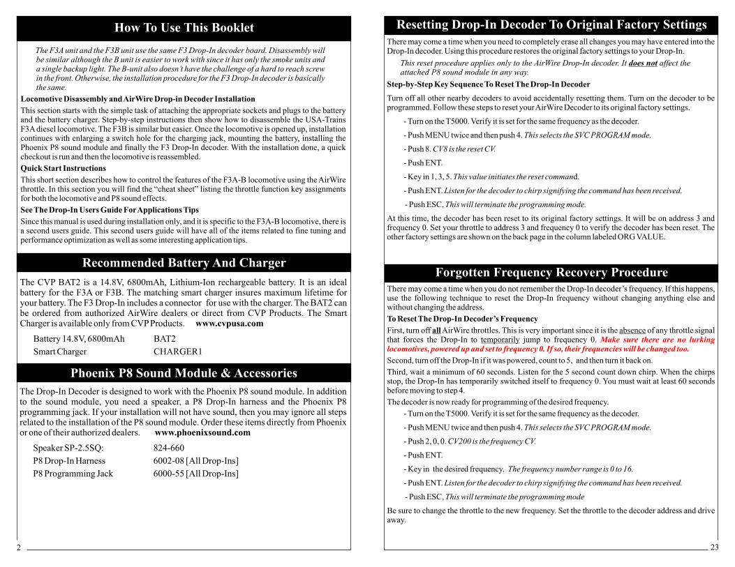
The F3A unit and the F3B unit use the same F3 Drop-In decoder board. Disassembly will be similar although the B unit is easier to work with since it has only the smoke units and a single backup light. The B-unit also doesn’t have the challenge of a hard to reach screw in the front. Otherwise, the installation procedure for the F3 Drop-In decoder is basically the same.
Locomotive Disassembly and AirWire Drop-in Decoder Installation
This section starts with the simple task of attaching the appropriate sockets and plugs to the battery and the battery charger. Step-by-step instructions then show how to disassemble the USA-Trains F3A diesel locomotive. The F3B is similar but easier. Once the locomotive is opened up, installation continues with enlarging a switch hole for the charging jack, mounting the battery, installing the Phoenix P8 sound module and finally the F3 Drop-In decoder. With the installation done, a quick checkout is run and then the locomotive is reassembled.
Quick Start Instructions
This short section describes how to control the features of the F3A-B locomotive using the AirWire throttle. In this section you will find the “cheat sheet” listing the throttle function key assignments for both the locomotive and P8 sound effects.
See The Drop-In Users Guide For Applications Tips
Since this manual is used during installation only, and it is specific to the F3A-B locomotive, there is a second users guide. This second users guide will have
some interesting application tips. all of the items related to fine tuning and
performance optimization as well as
There may come a time when you need to completely erase all changes you may have entered into the Drop-In decoder. Using this procedure restores the original factory settings to your Drop-In.
This reset procedure applies only to the AirWire Drop-In decoder. It does not affect the attached P8 sound module in any way.
Step-by-Step Key Sequence To Reset The Drop-In Decoder
Turn off all other nearby decoders to avoid accidentally resetting them. Turn on the decoder to be programmed. Follow these steps to reset your AirWire Decoder to its original factory settings.
- Turn on the T5000. Verify it is set for the same frequency as the decoder.
- Push MENU twice and then push 4. This selects the SVC PROGRAM mode.
- Push 8. CV8 is the reset CV.
- Push ENT.
- Key in 1, 3, 5. This value initiates the reset command.
- Push ENT. Listen for the decoder to chirp signifying the command has been received.
- Push ESC, This will terminate the programming mode.
At this time, the decoder has been reset to its original factory settings. It will be on address 3 and frequency 0. Set your throttle to address 3 and frequency 0 to verify the decoder has been reset. The other factory settings are shown on the back page in the column labeled ORG VALUE.
Resetting Drop-In Decoder To Original Factory Settings
Forgotten Frequency Recovery Procedure
Phoenix P8 Sound Module & Accessories
Recommended Battery And Charger
The Drop-In Decoder is designed to work with the Phoenix P8 sound module. In addition to the sound module, you need a speaker, a P8 Drop-In harness and the Phoenix P8 programming jack. If your installation will not have sound, then you may ignore all steps related to the installation of the P8 sound module. Order these items directly from Phoenix or one of their authorized dealers. www.phoenixsound.com
Speaker SP-2.5SQ: 824-660
P8 Drop-In Harness 6002-08 [All Drop-Ins]
P8 Programming Jack 6000-55 [All Drop-Ins]
The CVP BAT2 is a 14.8V, 6800mAh, Lithium-Ion rechargeable battery. It is an ideal battery for the F3A or F3B. The matching smart charger insures maximum lifetime for your battery. The F3 Drop-In includes a connector for use with the charger. The BAT2 can be ordered from authorized AirWire dealers or direct from CVP Products. The Smart Charger is available only from CVP Products. www.cvpusa.com
Battery 14.8V, 6800mAh BAT2
Smart Charger CHARGER1
There may come a time when you do not remember the Drop-In decoder’s frequency. If this happens, use the following technique to reset the Drop-In frequency without changing anything else and without changing the address.
To Reset The Drop-In Decoder’s Frequency
First, turn off all AirWire throttles. This is very important since it is the absence of any throttle signal that forces the Drop-In to temporarily jump to frequency 0.
Second, turn off the Drop-In if it was powered, count to 5, and then turn it back on.
Third, wait a minimum of 60 seconds. Listen for the 5 second count down chirp. When the chirps stop, the Drop-In has temporarily switched itself to frequency 0. You must wait at least 60 seconds before moving to step 4.
The decoder is now ready for programming of the desired frequency.
Be sure to change the throttle to the new frequency. Set the throttle to the decoder address and drive away.
Make sure there are no lurking locomotives, powered up and set to frequency 0. If so, their frequencies will be changed too.
- Turn on the T5000. Verify it is set for the same frequency as the decoder.
- Push MENU twice and then push 4. This selects the SVC PROGRAM mode.
- Push 2, 0, 0. CV200 is the frequency CV.
- Push ENT.
- Key in the desired frequency. The frequency number range is 0 to 16.
- Push ENT. Listen for the decoder to chirp signifying the command has been received.
- Push ESC, This will terminate the programming mode
322
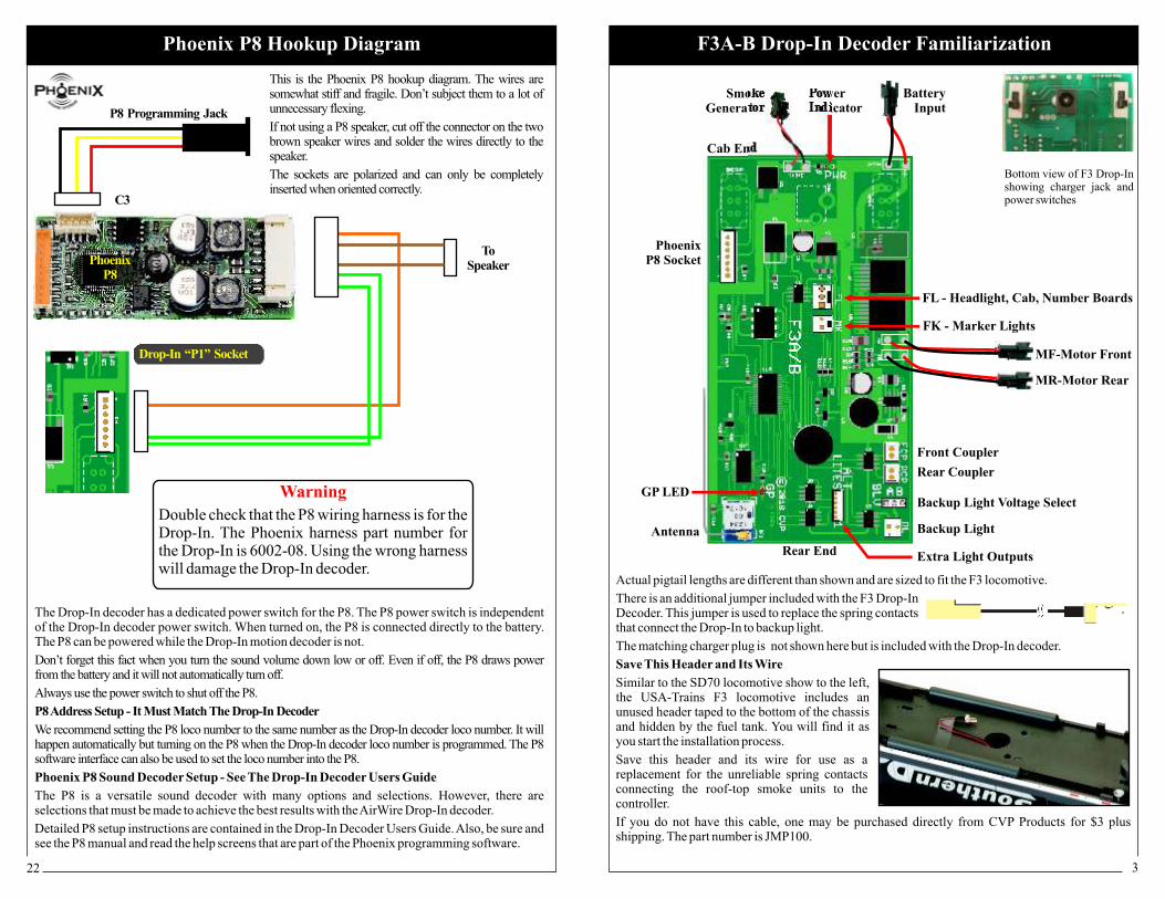
Double check that the P8 wiring harness is for the Drop-In. The Phoenix harness part number for the Drop-In is 6002-08. Using the wrong harness will damage the Drop-In decoder.
Actual pigtail lengths are different than shown and are sized to fit the F3 locomotive.
There is an additional jumper included with the F3 Drop-In Decoder. This jumper is used to replace the spring contacts that connect the Drop-In to backup light.
The matching charger plug is not shown here but is included with the Drop-In decoder.
Save This Header and Its Wire
Similar to the SD70 locomotive show to the left, the USA-Trains F3 locomotive includes an unused header taped to the bottom of the chassis and hidden by the fuel tank. You will find it as you start the installation process.
Save this header and its wire for use as a replacement for the unreliable spring contacts connecting the roof-top smoke units to the controller.
If you do not have this cable, one may be purchased directly from CVP Products for $3 plus shipping. The part number is JMP100.
F3A-B Drop-In Decoder FamiliarizationPhoenix P8 Hookup Diagram
C3
P8 Programming Jack
ToSpeaker
This is the Phoenix P8 hookup diagram. The wires are somewhat stiff and fragile. Don’t subject them to a lot of unnecessary flexing.
If not using a P8 speaker, cut off the connector on the two brown speaker wires and solder the wires directly to the speaker.
The sockets are polarized and can only be completely inserted when oriented correctly.
The Drop-In decoder has a dedicated power switch for the P8. of the Drop-In decoder power switch. When turned on, the P8 is connected directly to the battery. The P8 can be powered while the Drop-In motion decoder is not.
Don’t forget this fact when you turn the sound volume down low or off. Even if off, the P8 draws power from the battery and it will not automatically turn off.
Always use the power switch to shut off the P8.
The P8 power switch is independent
P8 Address Setup - It Must Match The Drop-In Decoder
We recommend setting the P8 loco number to the same number as the Drop-In decoder loco number. It will happen automatically but turning on the P8 when the Drop-In decoder loco number is programmed. The P8 software interface can also be used to set the loco number into the P8.
Phoenix P8 Sound Decoder Setup - See The Drop-In Decoder Users Guide
The P8 is a versatile sound decoder with many options and selections. However, there are selections that must be made to achieve the best results with the AirWire Drop-In decoder.
Detailed P8 setup instructions are contained in the Drop-In Decoder Users Guide. Also, be sure and see the P8 manual and read the help screens that are part of the Phoenix programming software.
PhoenixP8
Drop-In “P1” Socket
Bottom view of F3 Drop-In showing charger jack and power switches
Cab End
Rear End
MF-Motor Front
MR-Motor Rear
SmokeGenerator
Backup Light
Extra Light Outputs
Backup Light Voltage Select
FK - Marker Lights
FL - Headlight, Cab, Number Boards
Power Indicator
Antenna
Battery Input
Phoenix P8 Socket
GP LED
Front Coupler
Rear Coupler
Warning
214
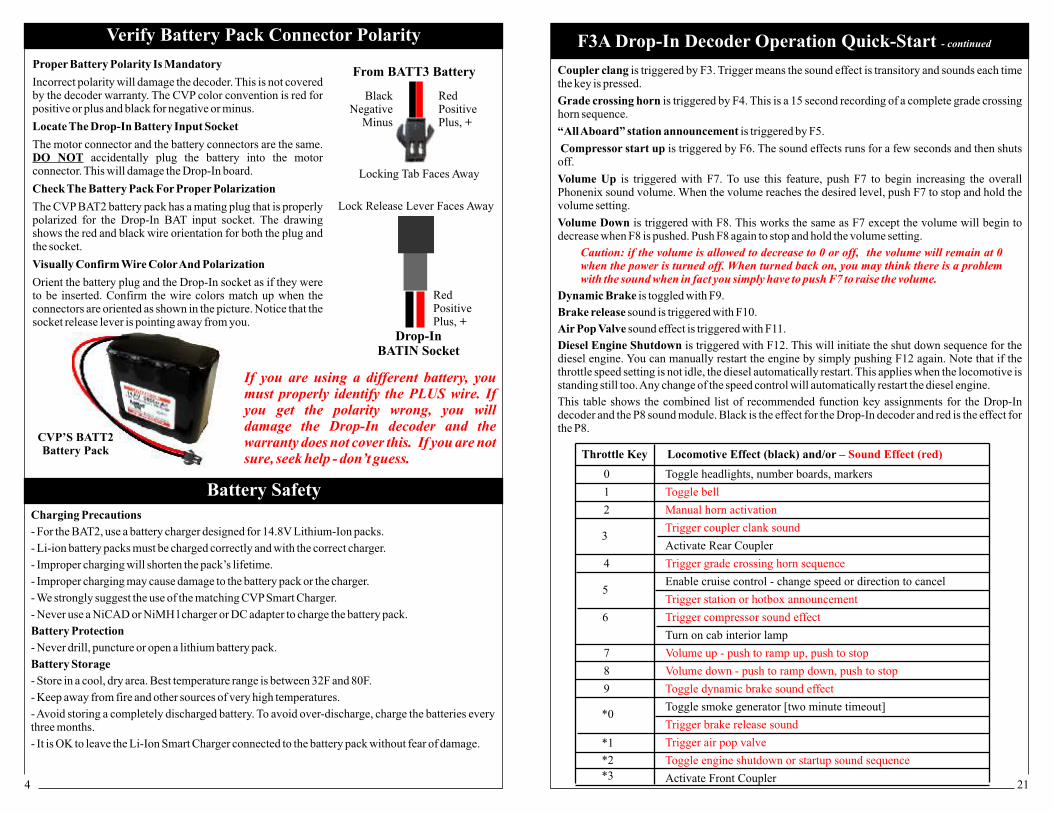
Coupler clang is triggered by F3. Trigger means the sound effect is transitory and sounds each time the key is pressed.
Grade crossing horn is triggered by F4. This is a 15 second recording of a complete grade crossing horn sequence.
“All Aboard” station announcement is triggered by F5.
Compressor start up is triggered by F6. The sound effects runs for a few seconds and then shuts off.
Volume Up is triggered with F7. To use this feature, push F7 to begin increasing the overall Phonenix sound volume. When the volume reaches the desired level, push F7 to stop and hold the volume setting.
Volume Down is triggered with F8. This works the same as F7 except the volume will begin to decrease when F8 is pushed. Push F8 again to stop and hold the volume setting.
Dynamic Brake is toggled with F9.
Brake release sound is triggered with F10.
Air Pop Valve sound effect is triggered with F11.
Diesel Engine Shutdown is triggered with F12. This will initiate the shut down sequence for the diesel engine. You can manually restart the engine by simply pushing F12 again. Note that if the throttle speed setting is not idle, the diesel automatically restart. This applies when the locomotive is standing still too. Any change of the speed control will automatically restart the diesel engine.
This table shows the combined list of recommended function key assignments for the Drop-In decoder and the P8 sound module. Black is the effect for the Drop-In decoder and red is the effect for the P8.
Caution: if the volume is allowed to decrease to 0 or off, the volume will remain at 0 when the power is turned off. When turned back on, you may think there is a problem with the sound when in fact you simply have to push F7 to raise the volume.
0 Toggle headlights, number boards, markers
1
2
Activate Rear Coupler
4
Enable cruise control - change speed or direction to cancel
Turn on cab interior lamp
7
8
9
Toggle smoke generator [two minute timeout]
Activate Front Coupler
Toggle bell
Manual horn activation
Trigger coupler clank sound
Trigger grade crossing horn sequence
Trigger station or hotbox announcement
Trigger compressor sound effect
Volume up - push to ramp up, push to stop
Volume down - push to ramp down, push to stop
Toggle dynamic brake sound effect
Trigger brake release sound
Trigger air pop valve
Toggle engine shutdown or startup sound sequence
Throttle Key Locomotive Effect (black) and/or – Sound Effect (red)
F3A Drop-In Decoder Operation Quick-Start - continued
Proper Battery Polarity Is Mandatory
Incorrect polarity will damage the decoder. This is not covered by the decoder warranty. The CVP color convention is red for positive or plus and black for negative or minus.
Locate The Drop-In Battery Input Socket
The motor connector and the battery connectors are the same. DO NOT accidentally plug the battery into the motor connector. This will damage the Drop-In board.
Check The Battery Pack For Proper Polarization
The CVP BAT2 battery pack has a mating plug that is properly polarized for the Drop-In BAT input socket. The drawing shows the red and black wire orientation for both the plug and the socket.
Visually Confirm Wire Color And Polarization
Orient the battery plug and the Drop-In socket as if they were to be inserted. Confirm the wire colors match up when the connectors are oriented as shown in the picture. Notice that the socket release lever is pointing away from you.
RedPositivePlus, +
BlackNegative
Minus
Locking Tab Faces Away
From BATT3 Battery
Drop-In BATIN Socket
Lock Release Lever Faces Away
RedPositivePlus, +
If you are using a different battery, you must properly identify the PLUS wire. If you get the polarity wrong, you will damage the Drop-In decoder and the warranty does not cover this. If you are not sure, seek help - don’t guess.
Battery SafetyCharging Precautions
- For the BAT2, use a battery charger designed for 14.8V Lithium-Ion packs.
- Li-ion battery packs must be charged correctly and with the correct charger.
- Improper charging will shorten the pack’s lifetime.
- Improper charging may cause damage to the battery pack or the charger.
- We strongly suggest the use of the matching CVP Smart Charger.
- Never use a NiCAD or NiMH l charger or DC adapter to charge the battery pack.
Battery Protection
- Never drill, puncture or open a lithium battery pack.
Battery Storage
- Store in a cool, dry area. Best temperature range is between 32F and 80F.
- Keep away from fire and other sources of very high temperatures.
- Avoid storing a completely discharged battery. To avoid over-discharge, charge the batteries every three months.
- It is OK to leave the Li-Ion Smart Charger connected to the battery pack without fear of damage.
Verify Battery Pack Connector Polarity
CVP’S BATT2Battery Pack
*2
3
*1
*0
6
5
*3

520
Replace The Roof-Top DetailsDon’t forget to reinstall the air horn assembly you removed prior to beginning loco disassembly.
Locomotive Motion ControlSpeed and direction are controlled from the throttle. Use the throttle’s knob to change speed. To change direction, push the direction key. “Forward” direction is defined as if you were sitting in the locomotive cab.
Cruise control activation is easy. Once the locomotive is running at the desired speed, push F5 to activate cruise control. A beep will be heard when cruise control is activated. To deactivate cruise control simply change the speed or direction. A beep will be heard when cruise control is deactivated. At very slow speeds, you may hear a double beep. This means that the locomotive is going too slow for reliable cruise control so you need to increase the speed slightly and push F5 again.
Locomotive Lighting and Smoke Generator ControlHeadlights, number boards, and marker lights are all turned on and off with the throttle’s 0 key. This is function 0 which we shorten to F0. When going in reverse, The front headlight automatically turns off and the rear headlight turns on. The front marker lights are red when going in the reverse direction.
Cab interior light is turned on and off with F6.
Smoke unit is toggled on and off with F10. Once turned on, the smoke generator has an automatic 2 minute timeout. However, if the smoke fluid has run out, the locomotive’s own smoke generator controller will turn off even if the 3 minute timer has not run out. Remember, F10 is the * key followed by the 0 key. Do not depend on the factory installed smoke controller circuit to shut off the Smoke unit. The timer can be set to any value from 1 minute to 255 minutes. The original setting is 3 minues.
Phoenix P8 Sound Effects ControlThe table on the next page assumes you have used the recommended configuration file or have set up the P8 to match our recommended settings (see page 21). If you have not yet configured the P8, the sound effects and throttle activation keys will not match and the sound may shut off after only a few minutes of operation. This is normal if the configuration has not been changed - it is not a Drop-In or sound module problem.
Bell is toggled on and off by F1. Toggle means push and release the F1 key to turn on the bell. To turn off the bell, push F1 again.
Horn is activated by F2. This is a momentary activation which means push to turn on and release to turn off. There is an automatic timer tied to the horn activation. Sometimes, when the horn is activated, it does not receive the turn off command. This can be caused by motor noise, distance from the throttle or momentary jamming. To prevent the horn from being stuck on, the Drop-In decoder will automatically shut off the horn.
Coupler clang is triggered by GP30. Trigger means the sound effect is transitory and sounds each time the key is pressed.
Grade crossing horn is triggered by F4. This is a 15 second recording of a complete grade crossing horn sequence.
“All Aboard” (or hot-box) announcement is triggered by F5.
Compressor start up is triggered by F6. The sound effects runs for a few seconds and then shuts off.
continued on next page
F3A Drop-In Decoder Operation Quick-Start Attaching Charger Plug Pigtail To Charger
First, open up the charger box. Inside will be the charger with alligator clips and the AC power cord.
Locate the charger pigtail that came with your AirWire Drop-In decoder. The 2-conductor pigtail comes with stripped wires on one end and a right angle plug on the other.
The pigtail needs to be permanently attached to the charger output wires. This is not difficult and no special tools are needed.
Wire polarity is very important and reversing the polarity could damage the charger or the battery or both. On the pigtail, the plus wire is the wire with the white stripe. The minus wire is the solid black wire. The charger uses the conventional red wire for plus and black for the minus wire.
Take the pigtail and separate the 2 wires for about 2 inches. Cut the plus wire so it is 1 inch shorter than the minus wire. Remove about ½ inch of insulation from the plus wire. Twist and apply solder to the twist end of the plus wire. Next, remove about ½ inch of the insulation from the minus wire. Twist the strands together and touch a tiny bit of solder to the twisted wire.
Take the charger wires and split the red and black wires apart for about 3 inches. Cut off the alligator clips and cut the minus (black) wire so it is shorter than the plus (red) wire. Remove about ½ inch of the insulation from both the black and red ends of the wires. Twist and tin the wires.
If you are using heatshrink tubing to insulate the solder joints, now is the time to slide a piece over the minus wire. Otherwise, use electrical tape to insulate each connection. Overlap or twist together the two minus wires and solder them together. Once the solder joint has cooled, slide the heatshrink over the connection and heat it up to shrink the tubing around the connection. Make sure no wire is visible.
Slide a piece of heatshrink over the plus wire. Overlap or twist together the two plus wires and solder them together. Once the solder joint has cooled, slide the heatshrink over the connection and heat it up to shrink the tubing around the connection. Make sure no wire is visible.
Inspect for proper polarity matching and that no bare wire is visible outside the heatshrink tubing. This completes the wiring.
This is called tinning and keeps the twisted wires from unraveling.
Heatshrink TubingNo Stripe/Minus
MinusBlack Wire
Plus/Red WireWhite Stripe/Plus
Charger Wires
Heatshrink tubing may be ordered from Mouser Electronics. Use 0.25 inch diameter tubing with part number 5174-1141. It sells for about $2 and comes in a 4 foot length. www.mouser.com
From Charger Plug

196
Warning: Many parts of the shell and chassis are fragile and easily break. Especially vulnerable are the steps, doors, side-frame assemblies, window detail. Gently pull up and remove both of the horn assemblies and the little steam vent near the rear.
You Must Have The Proper Screwdriver
You must have a thin-shafted, #1 phillips-head screwdriver that is at least 4 inches long to reach the screws. The thin shaft is necessary to fit between the wheel and side frame. This one is from General and has a 4 inch long, narrow shaft with a #1 Philips tip. It is also magnetized which comes in handy for pulling the screws from deep recesses.
A Soft Work Surface Pays Big Dividends
Spread a couple layers of thick towels on your work surface to serve as a cushion for the locomotive. The top of the locomotive is uneven and is unstable when upside down. The towel will help prevent damage should it fall over.
Use a Foam Block To Hold Screws
Take a rectangular sheet of foam and label it B and F to represent the loco’s front and back end. As each screw is removed, position it in the foam at about the same location as found on the locomotive.
Total Mounting Screw Count is 11
When all the screws are removed, there will be a total of 11 screws. When you are done, if your count doesn’t match, go back and check to see which ones you missed. The next series of illustrations shows the location of the screws and have been numbered for easy reference.
Remove Fuel Tank - 2 Screws
The 2 screws are numbered below and the black circles show where you will find the screws. Remove the 2 screws, place them in the foam block, then lift off the tank and set it aside for now.
USA-Trains F3A-B Disassembly
21
Common Errors and Fixes
Make sure everything checks - you don’t want to have to take the locomotive apart more than once.
Closing Up The Locomotive
This will take a few minutes and can be the toughest part of the job. Don’t rush - take your time. The first task is to push the P8 programming plug up through the round hole in the chassis and plug it into the P8.
Next, bundle the backup light wiring and smoke unit wiring together. Use some tape to fasten the backup light wiring to the roof of the shell. Keep it away from the all the mounting posts. Lift the shell over the chassis and observe the wiring. To insure that the wires don’t obstruct the mounting posts, make sure that they naturally fall inside, and between the mounting posts. Use additional tape, twist ties or cable ties if necessary to keep them in place. Continue to bring the top half down onto the chassis. Watch and make sure all wires are INSIDE the mounting posts.
Look on both sides of the locomotive.
The bundle of wires going to the cab area lights are the ones that generally cause trouble with the mounting screw #3 which is near the coupler pocket. Make sure they all go through the notch in the wall. You can lift up the shell a bit to verify that the wires are clear of the mounting hole.
The two halves should seat themselves correctly although the nose may droop a bit until the #3 screw is installed. It is easy to be off by a small amount which will prevent the two halves from mating. Once the two halves are together, turn the locomotive on its side or on its back. If upside down, do not strain the speaker and programming wires. Install the #3 screw first.
Then install the rear end screws.
Before mounting the fuel tank, push the extra speaker and programming wires up through the hole in the floor. No wires should be allowed to touch the black speaker cone or the sound will distort. Now attach the fuel tank. Finish the reassembly by installing the remaining screws.
If A Screw Just Spins
If a screw spins in the hole without tightening, the hole is not stripped. Rather the top and bottom halves are too far apart or slightly misaligned. This can be caused by a wire that is pinched between the two halves. Take the locomotive apart and try again. If you find a broken wire, splice it. If just kinked or creased, move it out of the way and fasten it down before continuing. Always insulate splices. No bare wires are allowed inside the locomotive.
Green Power LED doesn’t turn on: Make sure the BOTH Drop-In decoder power switches are on. The sound module switch is independent of the Drop-In decoder switch.
Red GP LED only has a very slow flash rate: This is your indication that nothing is being received from the throttle. The throttle has either turned itself off, or is on the wrong frequency.
Don’t allow a wire to fall on the outside of the post or you risk pinching it when the top half is mated to the bottom half.
Keep all wires as far away from the antenna as possible.
To start the screw, first turn it slightly counter-clockwise to get it seated in the threads, then turn it clockwise to tighten. Do not over tighten.
Be very careful with the antenna. If it is cut by a mounting screw, you’ll get poor reception and it will have to be replaced.
F3A-B Closing Up The Locomotive
Drop-In Power Switch [shown OFF]
Battery Charger Jack
Phoenix P8 Module Power Switch [shown OFF]
Power Switches And Charger Jack
Move the switches towards the cab to turn on the Drop-In decoder and the P8 sound module. The switches must be off to charge the battery.

718
USA-Trains F3A-B Disassembly
Cab End Mounting Screws - 3 Screws
You will need to rotate the truck to see the holes in which the screws will be found. The screws are located in deep hollow tubes and you will need to use the long, thin-shafted screw driver.
Take care not to damage the truck wiring. Be careful not to damage the side frame’s delicate detail.
The number 3 screw may be difficult to see. Its hole is directly behind the coupler pocket. Rotate the truck to see it better. Wedge the screwdriver into the hole while gently pushing the truck away. You can also remove the side frame to provide better visibility.
If a screw does not come out with the screwdriver’s magnetic tip, give the screw several more turns to insure it has released from the upper shell. The screw is usually hung in the burrs at the end of the tube. Just make sure it has released from the top shell. You can retrieve it once the top and bottom sections are separated.
As each screw is removed, place it into the foam block.
Under Fuel Tank Mounting Screws - 4 Screws
Remove the 4 screws that are visible once the fuel tank is removed. Place the screws into the foam block.
3
4
5
6
8
7
9
Quick Start - Setting Address and Frequency
Your Drop-In decoder features an all new and much improved method for setting its radio frequency. Unlike the older style Drop-In decoder, there isn’t a tiny rotary frequency selector switch. In its place is a new RF module that uses your throttle to set the frequency. With this new module, you may change the frequency at any time and without opening up the locomotive.
The “Quick Start” section assumes you have already installed your Drop-In. As delivered from the factory, the Drop-In’s frequency is set for 0 and the locomotive address is 3. The steps below are for the T5000 throttle. If you have a different throttle, refer to your throttle’s user guide.
Note, the LEDs may not be visible in your locomotive. If so, just ignore the comments but do follow the instructions in sequence.
Step 1: Turn Power on to the Drop-In and Turn on Throttle! The Drop-In’s power green LED and the red GP LED will glow brightly indicating power is connected and the throttle is being received. ! If you have not done so, set the throttle to frequency 0. Assuming your Drop-In still has the factory default address setting, also set the throttle’s locomotive number to 3.
Step 2: Set the Drop-In Decoder Address! Press the green menu key twice and then push the number 4 to select SVC PROGRAM mode. ! Push 1 and push ENT which selects CV1 which is where the loco number is stored inside the decoder. ! Key in the desired loco number you want to use. The loco number should be unique. The loco’s cab number is always a good idea. Once you have entered the numbers, push ENT. [Loco number 0 is not allowed]. The decoder will chirp when it gets the command.! Push ESC when done.
Step 3: set the throttle to the new loco number and verify that the loco runs
Step 4: Changing The Drop-In Frequency
! Press the green menu key twice and then push the number 4 to select SVC PROGRAM mode.
! Key in 2, 0, 0 and push ENT which selects CV200 which is where the decoder frequency is stored.! Key in the desired frequency (range is 0 to 16) then push ENT. ! Enter the desired frequency number and push ENT. Your Drop-In is now on the new frequency.
! Push ESC to cancel SVC PROGRAM mode.
! Step 5: Set the Throttle to the new frequency and verify the loco runs.
To store the loco number and frequency combination inside the throttle’s memory, push the LOCO MEM key twice.
Quick-Start - Resetting The Drop-In FrequencyThere may come a time when your locomotive no longer responds to what you believe is the correct frequency, or you can not remember the correct frequency. Here’s how to reset the frequency
Step 1 Turn off all AirWire throttles. This is very important since it is the of the absence of a throttle signal, plus a decoder power-cycle (turning the decoder’s power off and then back) that allows the decoder to temporarily jump to frequency 0 where you can set a new frequency.
Step 2 Turn off the Drop-In decoder if it was powered on.
Step 3 Turn on the Drop-In decoder and wait at least one minute. Do not turn on any throttles during this time. After one minute, the Drop-In will chirp 5 times and will be temporarily on frequency 0.
Step 4 Turn on your throttle, and set it to frequency 0.
Step 5 - Use SVC PROGRAM to set CV200 to the desired frequency. The locomotive address does not matter when using SVC PROGRAM mode. Be sure and make a note of the new frequency. When done, power-cycle the decoder to accept the new frequency.

178
10
11
USA-Trains F3A-B Disassembly
Rear Mounting Screws - 2 Screws
The last 2 screws are located in hollow tubes that the truck partially obscures. Rotate the truck to expose the holes and remove the last two screws.
Check Your Screw Count
With all screws now removed, take a moment and compare your count and foam board holder to the one below. The total count is 11. If your count is different, you’ve missed one. Go back and find the missing screw and remove it. If it is hung in the tube, that is OK, just make sure the screw has been released from the top half. If all screws are not removed, the top shell and bottom chassis can not be separated.
Separate The Top Shell From The Chassis
Turn the locomotive over and gently remove the shell. It will separate easily if all the screws have been removed. If it doesn’t come apart, you have missed a screw. Find it and remove it.
F3A-B Preliminary Checkout
Red GP LED
Green Power LED
Preliminary CheckoutAs delivered from the factory, the Drop-In decoder is set to locomotive number 3. The factory setting for the radio frequency is frequency 0.
1. Turn on both power switches on the Drop-In. The ON position is when the slide switch is towards the cab. The green LED will turn on indicating that battery power is present.
2. You will hear the Phoenix P8 module turn on (if installed). Don’t be alarmed if the sound turns off in a minute or so - that is normal and changing this feature is discussed in the Users Guide.
3. Turn on the throttle and set it for loco number 3. Also set the throttle to frequency 0. See your throttle manual for how to do this. Now look at the red GP LED - it will be on. It may appear to flicker a bit which is normal. This tells you that the address and frequency are set to match the throttle.
4. Slowly turn up the throttle until you see the motor attempt to move. Verify that both motors turn in the same direction.
5. Push the throttle’s 0 key to turn on the front headlight, number boards and front marker lights.Set the throttle for reverse and confirm the backup light turns on, the front markers are red and the headlight is off. Push 0 to turn off the headlights.
6. Push the 6 key to turn on the cab interior light.
7. To test the smoke unit, you must add a just 5 drops of smoke fluid to both smoke units. Make sure the cab is right side up when adding drops and testing the smoke unit. The smoke unit is turned on by pushing the * key followed by the 0 key. After a few minutes, smoke will appear or you will notice the warm air from the heater. Push * and 0 again to turn off the smoke unit. Do not rely on the factory smoke controller to automatically turn off - it is unreliable. Use the throttle to turn it off.
8. If you have installed the Phoenix sound decoder, push the 2 key and the P8 horn will sound.
This concludes the preliminary checkout. Rotate the antenna connector so the antenna wire is vertical for best reception. Keep it away from all wires.
What About The ALT LIGHT Connector?
Using the ALT LIGHT connector, requires the addition of more wires and installing extra LEDs to achieve the desired effect. Since these are not part of the standard installation, details are not covered in this installation manual. The use of the ALT LIGHT connector is described in the accompanying Drop-In user guide.
What About Fine Tuning?
All motion control settings, options and selections as well as changes to the frequency are made from the throttle. The Phoenix P8 settings are changed via the programming interface jack you mounted in the fuel tank. A summary of the P8 changes is on page 21. Complete information is in the Drop-In Users Guide.

916
If You Break A Wire...
We have noticed that some of the factory wires may be frayed or outright broken. If you notice this, stop and resolder the wire to the appropriate location. The most common wire breaks are on the smoke controller board, and the spring contact circuit board for the smoke units.
To resolder a broken wire, first remove the circuit board from the chassis. Next, strip the wire back about a quarter to half of an inch. Twist the copper strands tightly and then tin with a little solder. Then reinsert back into the circuit board. You may have to heat the back side to allow the wire to enter the hole.
Plugging In The Top Shell Connectors and Preparing For Preliminary Checkout
Double check the backup light voltage select jumper setting. As delivered from the factory, it is set for an FA locomotive. If in doubt, leave it across the A pins which is a low voltage setting. Before closing everything up, it is best to perform a preliminary checkout. This checkout verifies that everything is working and ready to go. For this checkout, you will need to connect the top shell connectors to their appropriate locations on the Drop-In decoder. Once everything checks OK, the locomotive will be ready for final reassembly
Bring the shell near to the chassis and plug in the connectors to the appropriate headers on the Drop-In board.
For the backup light, temporarily connect the jumper and plug it into the Drop-In. Also plug in the smoke unit to the new pigtail. Finally, plug in the speaker. The photo below shows the setup ready for preliminary testing. The P8 programming cable is not connected at this time.
USA-Trains F3A-B Disassembly
Backup LightBackup Voltage Select
Light FrontMarkers
Unplug All Connectors From Old Circuit Board and Remove The Board
This is relatively easy. Unplug all the connectors from the circuit board. Remove and save the little twist ties. These will be used later.
The lighting connectors are relatively robust and are held in place by friction. Grasp the white plug and pull straight up. Do not pull on the wires.
Disconnect the motor and pickup wires as well as the smoke generator controller connector from the main board. These connectors have a locking tab. To release the lock tab, push the down on the tab while gently pulling the connectors apart.
Remove the screw holding the small circuit board (indicated with the
Do not remove the light gray connector with the springs.
Finally, remove the 3 screws holding the old circuit board and remove it. Save the screws for mounting the new Drop-In decoder. .
Save the and Its Wires
The speaker header taped to the bottom of the chassis is unused. It is perfect for use as a replacement for the unreliable spring contacts used on the smoke generator wiring. Cut the wires at the old board and save the header for later use.
cyan colored arrow). Both may be discarded.
Remove the screw holding the 3 legged transistor to the front weight. Its wires are soldered to the old circuit board. It is no longer needed and can be discarded along with the old circuit board. The transistor on the rear weight is used with the smoke units and must be retained.
“Speaker Header”
“speaker header”
Push Here To Release Lock Tab
Connect Shell Lights and Smoke Unit
RemoveTransistor
Front Weight
Headlight, Caband Number Boards
Voltage Select Jumper
For the F3A loco, place the jumper across the middle and lower terminals marked by an A. The voltage to the rear bulb is 3.3V
For the F3B loco, place the jumper across the middle and upper terminals labeled B. The voltage to the rear bulb is equal to the battery voltage.

1510
Mount F3 Drop-In
Place the decoder onto the mounting posts. Make sure the jack and switches fit through the holes and the board is flush to the mounting posts. Verify the P8 plug and wires are not caught under the switches or charger jack. Use the 3 screws from the original circuit board to mount the Drop-In.
Plug In P8 Connector
Plug in the P8 cable to the white connector on the Drop-In. It only goes one way, so don’t force it.
Plug In Front Motor, Rear Motor, Smoke Controller and Battery Pack
Plug in the front and rear motor connectors. Plug in the battery pack. Be sure and connect the battery pack only to the proper socket on the Drop-In. Accidentally plugging it into a motor socket will damage the decoder. Finally, connect the smoke controller to the Drop-In’s smoke output.
Neatness Counts - Keep Wires Clear of Antenna
Make sure all wires lie between the tall mounting posts. Keep the wire bundles away from the antenna as much as possible. Arrange the wires to favor the side of the locomotive opposite of the antenna. The yellow tie-wraps make it easy to form the wire bundles and keep them in place.
The small tie-wraps are from Home Depot. Plastic twist ties are OK but don’t use twist-ties with a wire center. The wire might cause accidental short circuits if it becomes exposed.
Before mounting the Drop-In decoder, verify that both power switches are off. The actuators will be towards the rear of the locomotive when off.
The photos show the use of bright yellow 4 inch wire tie-wraps to manage all the wires.
USA-Trains F3A-B Disassembly
Removing The Font Truck - Optional But Recommended
The front truck and the connecting wires are in the way of the work that needs to be done to enlarge the switch holes to accept the F3 Drop-In decoder. Although the truck doesn’t have to be removed, it is real easy to nick or break the truck wires so we recommend removing it. It isn’t hard.
The truck is held with a single screw in the middle of the weight (red arrow). Remove the screw to free the truck. Retrieve the washer so as to avoid losing it. Gently pull the truck wire through the chassis hole and set the truck aside.
Enlarge Switch Openings In Chassis FloorLook at the bottom of the Drop-In board. Note the two switches and jack. The switches fit the outside switch holes in the locomotive floor. However, the area for the charging jack needs to be enlarged.
The area to be enlarged is outlined by a white box. Use a hobby knife or motor tool with an abrasive or routing bit to enlarge this area so the jack simply drops through. The jack must not bind. Temporarily mount the Drop-In board when the hole is complete. It must fit flush to the mounting posts (white arrows) and the jack must not bind in the opening. When you get a good fit, remove the Drop-In, clean away the debris and proceed on to the next step.
Reattach Front TruckWith the switch holes enlarged, you can now reattach the front truck. Feed the wires through the hole in the chassis floor. Do not forget the washer when attaching the truck.
Mounting The F3 Drop-In Decoder
Remove Track PickupsWhile the truck is detached from the chassis, now is a good time to remove the connector for the track pickups and track sliders. Find the large black connecter with 4 wires. The wires can be cut at the side frame and slipped off the truck pin. The smaller black plug with only two wires is for the motor.
Bend Antenna Vertical
The transistor must mount tightly to the lead weight. The weight is used as a heatsink. The transistor is used by the smoke controller board.
14 11
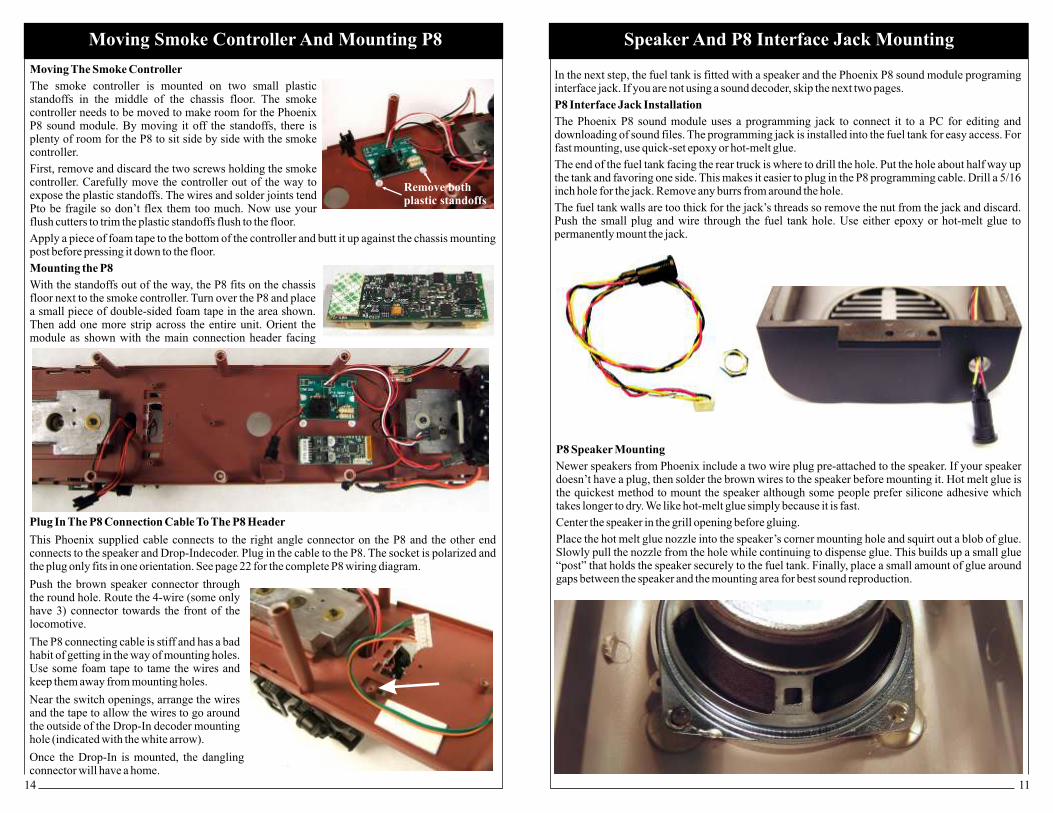
P8 Speaker Mounting
Newer speakers from Phoenix include a two wire plug pre-attached to the speaker. If your speaker doesn’t have a plug, then solder the brown wires to the speaker before mounting it. Hot melt glue is the quickest method to mount the speaker although some people prefer silicone adhesive which takes longer to dry. We like hot-melt glue simply because it is fast.
Center the speaker in the grill opening before gluing.
Place the hot melt glue nozzle into the speaker’s corner mounting hole and squirt out a blob of glue. Slowly pull the nozzle from the hole while continuing to dispense glue. This builds up a small glue “post” that holds the speaker securely to the fuel tank. Finally, place a small amount of glue around gaps between the speaker and the mounting area for best sound reproduction.
In the next step, the fuel tank is fitted with a speaker and the Phoenix P8 sound module programing interface jack. If you are not using a sound decoder, skip the next two pages.
P8 Interface Jack Installation
The Phoenix P8 sound module uses a programming jack to connect it to a PC for editing and downloading of sound files. The programming jack is installed into the fuel tank for easy access. For fast mounting, use quick-set epoxy or hot-melt glue.
The end of the fuel tank facing the rear truck is where to drill the hole. Put the hole about half way up the tank and favoring one side. This makes it easier to plug in the P8 programming cable. Drill a 5/16 inch hole for the jack. Remove any burrs from around the hole.
The fuel tank walls are too thick for the jack’s threads so remove the nut from the jack and discard. Push the small plug and wire through the fuel tank hole. Use either epoxy or hot-melt glue to permanently mount the jack.
Speaker And P8 Interface Jack MountingMoving Smoke Controller And Mounting P8
Moving The Smoke Controller
The smoke controller needs to be moved to make room for the Phoenix P8 sound module. By moving it off the standoffs, there is plenty of room for the P8 to sit side by side with the smoke controller.
First, remove and discard the two screws holding the smoke controller. Carefully move the controller out of the way to expose the plastic standoffs. The wires and solder joints tend Pto be fragile so don’t flex them too much. Now use your flush cutters to trim the plastic standoffs flush to the floor.
Apply a piece of foam tape to the bottom of the controller and butt it up against the chassis mounting post before pressing it down to the floor.
Mounting the P8
With the standoffs out of the way, the P8 fits on the chassis floor next to the smoke controller.
The smoke controller is mounted on two small plastic standoffs in the middle of the chassis floor.
Turn over the P8 and place a small piece of double-sided foam tape in the area shown. Then add one more strip across the entire unit. Orient the module as shown with the main connection header facing
Plug In The P8 Connection Cable To The P8 Header
This Phoenix supplied cable connects to the right angle connector on the P8 and the other end connects to the speaker and Drop-Indecoder. Plug in the cable to the P8. The socket is polarized and the plug only fits in one orientation. See page 22 for the complete P8 wiring diagram.
Push the brown speaker connector through the round hole. Route the 4-wire (some only have 3) connector towards the front of the locomotive.
The P8 connecting cable is stiff and has a bad habit of getting in the way of mounting holes. Use some foam tape to tame the wires and keep them away from mounting holes.
Near the switch openings, arrange the wires and the tape to allow the wires to go around the outside of the Drop-In decoder mounting hole (indicated with the white arrow).
Once the Drop-In is mounted, the dangling connector will have a home.
Remove bothplastic standoffs
1312
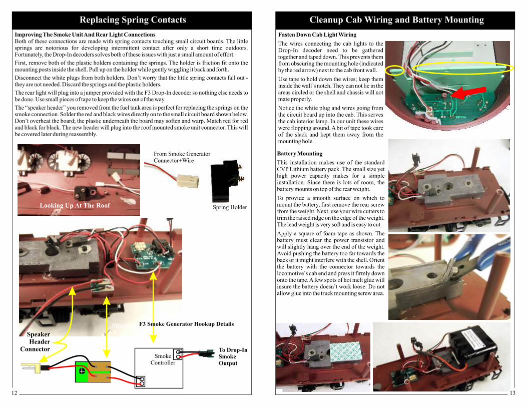
Fasten Down Cab Light Wiring
The wires connecting the cab lights to the Drop-In decoder need to be gathered together and taped down. This prevents them from obscuring the mounting hole (indicated by the red arrow) next to the cab front wall.
Use tape to hold down the wires; keep them inside the wall’s notch. They can not lie in the areas circled or the shell and chassis will not mate properly.
Notice the white plug and wires going from the circuit board up into the cab. This serves the cab interior lamp. In our unit these wires were flopping around. A bit of tape took care of the slack and kept them away from the mounting hole.
Cleanup Cab Wiring and Battery Mounting
Battery Mounting
This installation makes use of the standard CVP Lithium battery pack. The small size yet high power capacity makes for a simple installation. Since there is lots of room, the battery mounts on top of the rear weight.
To provide a smooth surface on which to mount the battery, first remove the rear screw from the weight. Next, use your wire cutters to trim the raised ridge on the edge of the weight. The lead weight is very soft and is easy to cut.
Apply a square of foam tape as shown. The battery must clear the power transistor and will slightly hang over the end of the weight. Avoid pushing the battery too far towards the back or it might interfere with the shell. Orient the battery with the connector towards the locomotive’s cab end and press it firmly down onto the tape. A few spots of hot melt glue will insure the battery doesn’t work loose. Do not allow glue into the truck mounting screw area.
Replacing Spring Contacts
Improving The Smoke Unit And Rear Light ConnectionsBoth of these connections are made with spring contacts touching small circuit boards. The little springs are notorious for developing intermittent contact after only a short time outdoors. Fortunately, the Drop-In decoders solves both of these issues with just a small amount of effort.
First, remove both of the plastic holders containing the springs. The holder is friction fit onto the mounting posts inside the shell. Pull up on the holder while gently wiggling it back and forth.
Disconnect the white plugs from both holders. Don’t worry that the little spring contacts fall out - they are not needed. Discard the springs and the plastic holders.
The rear light will plug into a jumper provided with the F3 Drop-In decoder so nothing else needs to be done. Use small pieces of tape to keep the wires out of the way.
The “speaker header” you removed from the fuel tank area is perfect for replacing the springs on the smoke connection. Solder the red and black wires directly on to the small circuit board shown below. Don’t overheat the board; the plastic underneath the board may soften and warp. Match red for red and black for black. The new header will plug into the roof mounted smoke unit connector. This will be covered later during reassembly.
Smoke Connector
Speaker Header
Connector
Spring Holder
From Smoke GeneratorConnector+Wire
Looking Up At The Roof
SmokeController
To Drop-InSmokeOutput
F3 Smoke Generator Hookup Details