Embed Size (px)
DESCRIPTION
K2 Systems
Citation preview
ASSEMBLY INSTRUCTIONSGround Mounted SySteM n-rack
concrete FoundatIon
GB
Mounting systems for solar technology
2
3
4
5
7
9
16
17
TABLE OF CONTENTS
THE COMPANY
SAFETY REGULATIONS
MATERIALS REQUIRED
TOOLS REQUIRED
ASSEMBLY
TERMS AND CONDITIONS
NOTES
Table of ConTenTs
2 | 18Content

PaRTneR WITH a sYsTeM
TesTeD QUalITY – foUR CeRTIfICaTIons
With sophisticated, fully developed product ideas and obvious customer-orientation, K2 Systems is your friendly partner in the field of mounting systems for solar technology.International customers appreciate the tried and tested designs for use on roofs or facades and in outdoor and individual solutions.
Mounting systems from K2 Systems impress with their attractive design and many well thought-out details. High grade materials and quality workmanship guarantee outstanding functionality and durability.
Our products consist of few yet perfectly matching components - this reduces the amount of material used, simplifies assembly while saving time and money.
As a young company, and in keeping with the times, we benefit from cooperation as partners in order to ensure the dynamic development of our company. The experiences from the personal dialogue with our customers forms the basis for permanent optimisation of our range of products.The team of K2 Systems looks forward to a successful cooperation with you.
K2 Systems stands for secure connection, highest quality and precision. Our customers and business partners have already known that for a long time. And three independent institutes have tested, confirmed and certified our capabilities and components.
3 | 18The Company
GeneRal safeTY InsTRUCTIons
Please be aware that our General Assembly Regulations must be adhered to.They can be viewed under http://www.k2-systems.de/english/downloads/customer-area.html.If you don’t already have them, you can obtain access data for our customer area on request.
In general, the following applies:
¬ Systems may only be installed and put into use by people who can ensure the proper carrying-out of the work due to their technical suitability (e.g. training or occupation) and/or experience.
¬ Before assembly, it must be checked that the product meets the local static requirements. For roof systems, the load-bearing capacity of the roof is also to be checked.
¬ National and local building regulations, standards and environmental regulations are always to be adhered to.
¬ Work safety and accident prevention regulations and corresponding standards and regulations of occupational associations are to be adhered to! In particular, it is to be ensured that: - Safety clothing is worn (especially safety helmets, work shoes and gloves). - For work on roofs, the regulations for working on roofs are to be adhered to (e.g. use of anti-fall guards, scaffolding with arrestor equipment from an eaves height of 3m etc.) - Presence of two people is vital for the entire course of the assembly, so that swift help can be ensured in the case of an accident.
¬ K2 mounting systems are constantly being developed further. Because of this, assembly procedures can change. Therefore, before assembly, always check that the assembly instructions are up-to-date under http://www.k2-systems.de/english/downloads/customer-area.html. We can also send you the latest version on request.
¬ The assembly instructions of the module manufacturer are to be adhered to.
¬ Earthing must be ensured, use lightning arrestor clamp if necessary.
¬ During the entire assembly time it is to be ensured that at least one copy of the assembly instructions is available on site.
¬ In the event of non-adherence to our General Safety Instructions and if competitor’s parts are built in or attached, K2 Systems GmbH reserves the right to refuse liability.
¬ If all safety instructions are adhered to and the system is correctly installed, there is a guarantee entitlement of 12 years! Please read out Terms and Conditions of Warranty which can be viewed under www.k2-systems.de/english/downloads. We can also send them to you on request.
¬ The dismantling of the system takes place according to the assembly steps, in reverse order.
4 | 18Safety Regulations
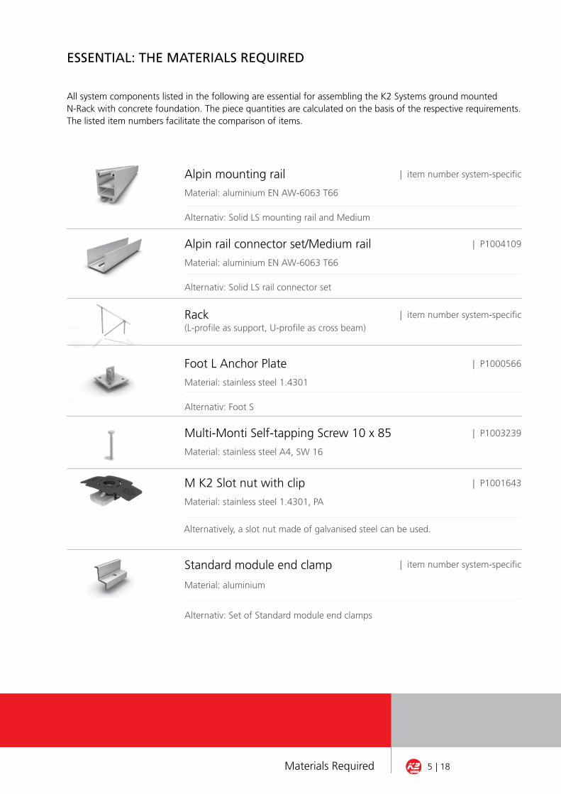
essenTIal: THe MaTeRIals ReQUIReD
All system components listed in the following are essential for assembling the K2 Systems ground mounted N-Rack with concrete foundation. The piece quantities are calculated on the basis of the respective requirements. The listed item numbers facilitate the comparison of items.
Alpin mounting rail
Material: aluminium EN AW-6063 T66
Alternativ: Solid LS mounting rail and Medium
Standard module end clamp
Material: aluminium
Alternativ: Set of Standard module end clamps
| P1000566Foot L Anchor Plate
Material: stainless steel 1.4301
Alternativ: Foot S
| P1003239Multi-Monti Self-tapping Screw 10 x 85
Material: stainless steel A4, SW 16
M K2 Slot nut with clip
Material: stainless steel 1.4301, PA
| P1001643
| item number system-specificRack(L-profile as support, U-profile as cross beam)
| item number system-specific
| item number system-specific
Alternatively, a slot nut made of galvanised steel can be used.
| P1004109Alpin rail connector set/Medium rail
Material: aluminium EN AW-6063 T66
Alternativ: Solid LS rail connector set
5 | 18Materials Required
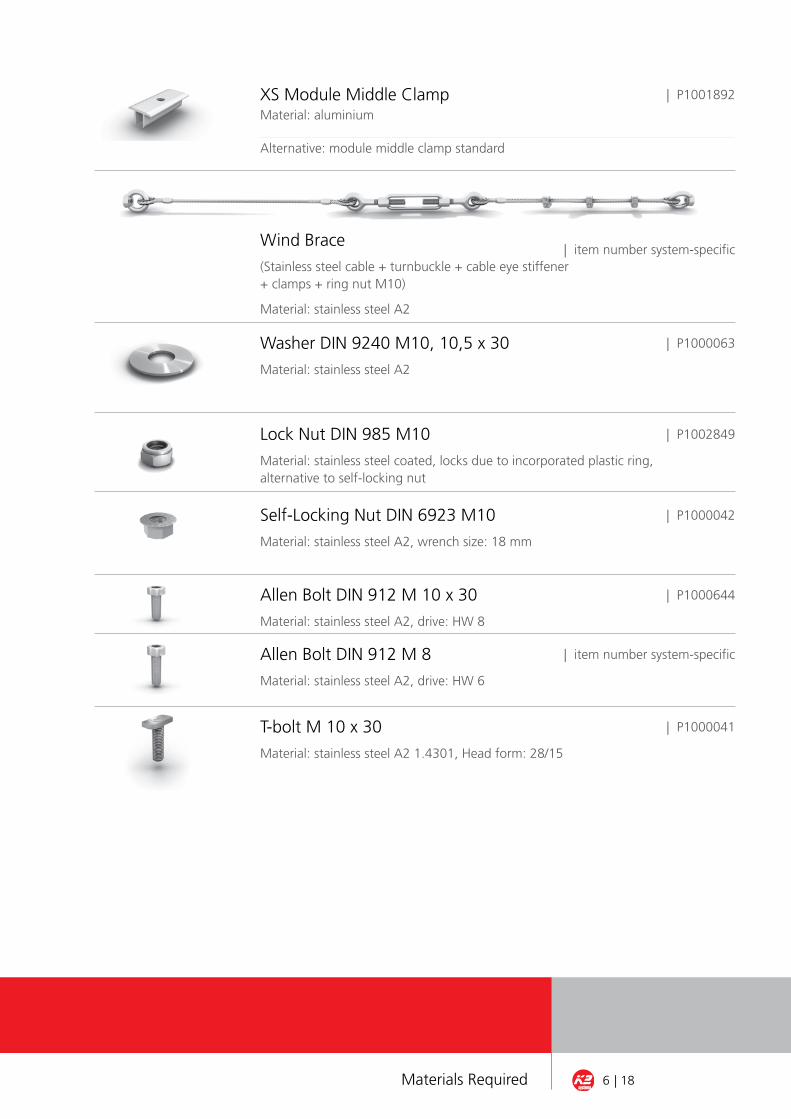
XS Module Middle ClampMaterial: aluminium
Alternative: module middle clamp standard
| item number system-specific
| P1000063
Wind Brace
(Stainless steel cable + turnbuckle + cable eye stiffener + clamps + ring nut M10)
Material: stainless steel A2
Washer DIN 9240 M10, 10,5 x 30
Material: stainless steel A2
| P1002849Lock Nut DIN 985 M10
Material: stainless steel coated, locks due to incorporated plastic ring,alternative to self-locking nut
| P1000042Self-Locking Nut DIN 6923 M10
Material: stainless steel A2, wrench size: 18 mm
Allen Bolt DIN 912 M 10 x 30
Material: stainless steel A2, drive: HW 8
Allen Bolt DIN 912 M 8
Material: stainless steel A2, drive: HW 6
T-bolt M 10 x 30
Material: stainless steel A2 1.4301, Head form: 28/15
| P1000644
| item number system-specific
| P1000041
| P1001892
6 | 18Materials Required
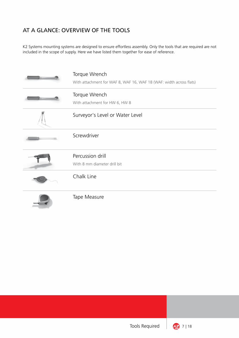
aT a GlanCe: oVeRVIeW of THe Tools
K2 Systems mounting systems are designed to ensure effortless assembly. Only the tools that are required are notincluded in the scope of supply. Here we have listed them together for ease of reference.
Surveyor‘s Level or Water Level
Screwdriver
Percussion drill
With 8 mm diameter drill bit
Chalk Line
Tape Measure
Torque Wrench
With attachment for WAF 8, WAF 16, WAF 18 (WAF: width across flats)
Torque Wrench
With attachment for HW 6, HW 8
7 | 18Tools Required

n-RaCK ConCReTe foUnDaTIon asseMblY: sTeP bY sTeP
In order to ensure safe and correct assembly of the system, please first read through all of the steps. For each step, the materials required are listed. If you have problems or questions relating to the system, ple-ase contact our
SERvICE-HOTLINE ON THE NUMBER: +49 (0) 7152-3560-0
GENERAL INSTRUCTION:
¬ The General Mounting Regulations absolutely must be adhered to. You will find these instructions under: www.k2-systems.de/english/downloads/customer-area.html If you don’t already have them, you can obtain access data for our customer area on request.
8 | 18Assembly of ground mounted N-Rack concrete

concrete Feet aSSeMBLy
The foundation(s) is/are constructed following the foundati-on plan. The foundation surface must be level.Use the chalk line and tape measure to determine and mark the position of the Foot L anchor plates. Maintain the minimum distance of the Foot L anchor plates to the edge of the foundation. Use a percussion drill to drill directly into the positions for the foot L anchor plates. Use self-tapping screws and washers to bolt the foot L anchor plates to the foundation. Make sure that all Foot L anchor plates are positioned at the same level and properly aligned. Assemble the foot L anchor plates in a level position.
Additional information:
¬ The foundation may be strip or block foundation in in-situ or precast concrete construction. The type of construction is defined by planning. Follow the planning guidelines.¬ To connect the wind braces to the foundation attach the wind brace connection area to the Foot L anchor plates.¬ The foot L anchor plates can be levelled by placing metal plates below them and checking them with a water level or levelling instrument.¬ For the self-tapping screws use an 8 mm diameter drill bit to drill to a depth of 90 mm. Fasten the self-tapping screws to the specified torque of 40 nm.
Required materials: Foundation on site, Foot L anchor pla-tes, 10 x 85 stainless steel self-tapping screws, M10 washer
1a of 13
1b of 13
9 | 18Assembly of ground mounted N-Rack concrete
n-RaCK ConCReTe foUnDaTIon asseMblY: sTeP bY sTeP
Assembly of ground mounted N-Rack concrete 10 | 18
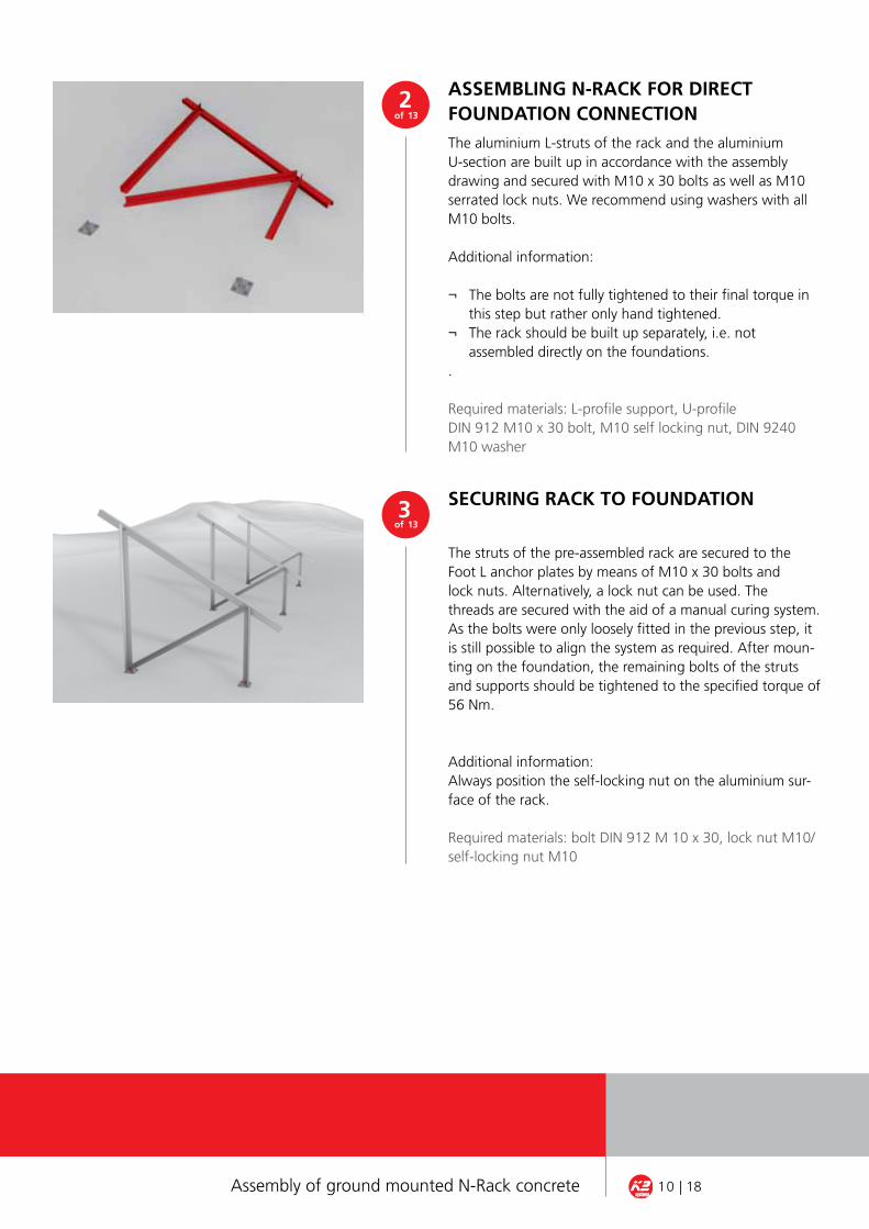
SecurInG rack to FoundatIon
The struts of the pre-assembled rack are secured to the Foot L anchor plates by means of M10 x 30 bolts andlock nuts. Alternatively, a lock nut can be used. Thethreads are secured with the aid of a manual curing system.As the bolts were only loosely fitted in the previous step, itis still possible to align the system as required. After moun-ting on the foundation, the remaining bolts of the strutsand supports should be tightened to the specified torque of56 Nm.
Additional information:Always position the self-locking nut on the aluminium sur-face of the rack.
Required materials: bolt DIN 912 M 10 x 30, lock nut M10/self-locking nut M10
3 of 13
The aluminium L-struts of the rack and the aluminiumU-section are built up in accordance with the assemblydrawing and secured with M10 x 30 bolts as well as M10serrated lock nuts. We recommend using washers with allM10 bolts.
Additional information:
¬ The bolts are not fully tightened to their final torque in this step but rather only hand tightened.¬ The rack should be built up separately, i.e. not assembled directly on the foundations..
Required materials: L-profile support, U-profileDIN 912 M10 x 30 bolt, M10 self locking nut, DIN 9240M10 washer
aSSeMBLInG n-rack For dIrect FoundatIon connectIon
2 of 13

4 of 13
Assembly of ground mounted N-Rack concrete 11 | 18
5 of 13
MountInG WInd BraceS
The wind braces are supplied preassembled. Should the wind braces need adjustment, carry out the following pro-cedure:The cable eye stiffeners are inserted in the ring of the ringnut and clamped together. The steel cable is then placedover the cable eye stiffeners, passed through the ring nutand secured with three cable clamps – each with two M5nuts – at the overlapping end of the steel cable. The clampsshould be evenly distributed. The first clamp should be secu-red as close as possible to the cable eye stiffener. The windbraces are now pulled taut with the aid of the turnbuckleand a screwdriver.Additional information:¬ Tighten the screws of the clamps to max. 4 Nm.¬ To ensure the steel cables can be retightened, a sufficient number of thread turns should be available in the turnbuckle after tightening.
Required materials: Wind brace
6 of 13
On structures with a wind brace, the lock nuts/serrated locknuts are replaced by the M10 ring nuts of the wind brace.
Additional information: Use high-strength thread lock to secure the ring nuts.
Required materials: DIN 912 M10 x 30 hexagon sockethead cap screw, M10 ring nut, High-strength thread lock
For WInd Brace: uSe rInG nutS
Use Allen screw and self-locking nut to screw together all foundation connections without wind brace connections.
Required materials: DIN 912 M10 x 30 hexagon sockethead cap screw, M10 lock nut
Additional information:Always position the self-locking nut on the aluminium sur-face of the rack. Alternatively to the self-locking nut, a lock nut can be used.
SecurInG FoundatIon connectIonS
Assembly of ground mounted N-Rack concrete 12 | 18
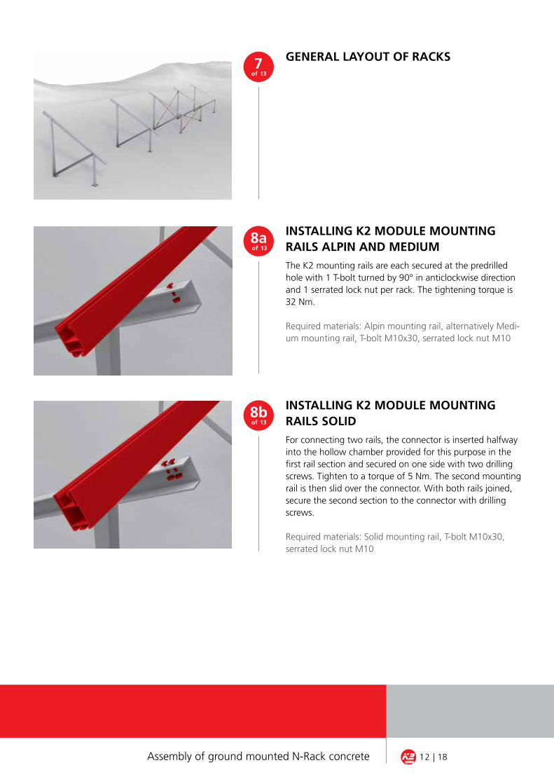
InStaLLInG k2 ModuLe MountInG raILS SoLIdFor connecting two rails, the connector is inserted halfwayinto the hollow chamber provided for this purpose in thefirst rail section and secured on one side with two drillingscrews. Tighten to a torque of 5 Nm. The second mountingrail is then slid over the connector. With both rails joined,secure the second section to the connector with drillingscrews.
Required materials: Solid mounting rail, T-bolt M10x30, serrated lock nut M10
8b of 13
The K2 mounting rails are each secured at the predrilled hole with 1 T-bolt turned by 90° in anticlockwise direction and 1 serrated lock nut per rack. The tightening torque is 32 Nm.
Required materials: Alpin mounting rail, alternatively Medi-um mounting rail, T-bolt M10x30, serrated lock nut M10
InStaLLInG k2 ModuLe MountInG raILS aLPIn and MedIuM
8a of 13
GeneraL Layout oF rackS 7 of 13
Assembly of ground mounted N-Rack concrete 13 | 18
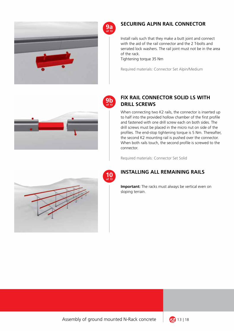
FIX raIL connector SoLId LS WItH drILL ScreWSWhen connecting two K2 rails, the connector is inserted upto half into the provided hollow chamber of the first profileand fastened with one drill screw each on both sides. Thedrill screws must be placed in the micro nut on side of theprofiles. The end-stop tightening torque is 5 Nm. Thereafter,the second K2 mounting rail is pushed over the connector.When both rails touch, the second profile is screwed to theconnector.
Required materials: Connector Set Solid
9b of 13
Install rails such that they make a butt joint and connect with the aid of the rail connector and the 2 T-bolts and serrated lock washers. The rail joint must not be in the area of the rack.Tightening torque 35 Nm
Required materials: Connector Set Alpin/Medium
SecurInG aLPIn raIL connector9a of 13
Neues Bild mit Alpin-Schiene und passendem verbinder-Set für Freiland
InStaLLInG aLL reMaInInG raILS
Important: The racks must always be vertical even onsloping terrain.
10 of 13

Assembly of ground mounted N-Rack concrete 14 | 18
FIttInG end cLaMP
FIXInG SPacInG BetWeen PaneLS
First insert the M K2 slot nut in the Solid rail and turn by 90°in clockwise direction. If the end and middle clamps comeas a set, fit the entire set on the rail. Secure the solar panelson the mounting rails according to the manufacturer’sinstructions and fix with end clamps, DIN 912 M8 hexagonsocket head cap screws and slot nuts at the ends of therows. Tightening torque 14 Nm
Required materials: M K2 slot nut, end clamps, DIN 912 M8hexagon socket head cap screw
Fixing with XS middle clamp
Use two XS middle clamps between two solar panels andscrew into the slotted nuts (DIN 912 M8 screws). Longerscrews are required for the XS middle clamp than for theStandard middle clamp. Tightening torque 14 Nm
Required materials: Slot nut, XS middle clamp, M8 screw
11 of 13
12a of 13
Fixing with Standard middle clamp
Use two Standard middle clamps between two solar panelsand screw into the slotted nuts (DIN 912 M8 screws). Tigh-tening torque 14 Nm
Required materials: Slot nut, Standard middle clamp,M8 screw
12b of 13
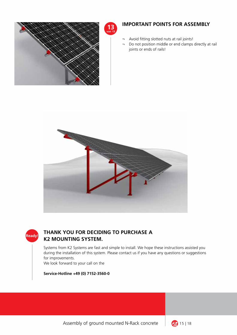
tHank you For decIdInG to PurcHaSe ak2 MountInG SySteM.
Systems from K2 Systems are fast and simple to install. We hope these instructions assisted you during the installation of this system. Please contact us if you have any questions or suggestions for improvements.We look forward to your call on the
Service-Hotline +49 (0) 7152-3560-0
ready!
Assembly of ground mounted N-Rack concrete 15 | 18
IMPortant PoIntS For aSSeMBLy
¬ Avoid fitting slotted nuts at rail joints!¬ Do not position middle or end clamps directly at rail joints or ends of rails!
13 von 13

§ 1 Ambit, contractual item1. Our General Business Terms and Conditions apply to the delivery of moveable merchandise in accordance with the contract concluded between us and the customer. These therefore also apply for all future business relations, even where they have not been expressly agreed upon once again.2. Our General Business Terms and Conditions apply exclusively. We do not recognise customer conditions contradictory to or deviating from our General Business Terms and Conditions, unless we have expressly approved their validity in writing. Our General Business Terms and Conditions also apply if, in circumstances where we are aware of customer conditions contradictory to or deviating from our General Business Terms and Conditions, we realise the delivery without any reservation.
§ 2 Offer, documentation at conclusion of contract1. The customer’s order represents a binding offer which we can accept within four weeks by forwarding an order confirmation or through delivery of the merchandise. Offers submitted by us in advance are non-binding.2. We reserve rights of ownership and copyright to all illustrations, drawings, calculations and other documents. This also applies to those written documents designated as “confidential”. The customer requires our express written permission prior to their transfer to third parties.3. Drawings, illustrations, dimensions, weights or other performance data are only binding when this is expressly agreed in writing.
§ 3 Prices and payment conditions1. The agreed remuneration must be paid. In cases where the price has increased at the time of performance of service as a result of a change in the market price or an increase in remuneration paid to third parties involved in performance of service, the higher price applies. The customer is entitled to withdraw from the contract if the higher price is twenty percent or more greater than the agreed price. This right must be exercised immediately on communication of the increased price.2. Prices should be understood with the addition of the mandatory turnover tax (vAT) valid on the day of invoicing.3. The complete remuneration should be paid within 14 days after receipt of the merchandise and without any discount, provided no other agreement has been reached. Statutory regula-tions governing the consequences relating to arrears of payments apply.4. The customer is only entitled to offset payment if his counterclaims have been determined to be valid, indisputable or are recognised by us. The customer is only entitled to exercise a right of retention if his counterclaim relates to the same contractual relationship.
§ 4 Time of performance, transfer of risk1. Delivery deadlines or delivery times which can be agreed upon as binding or non-binding require the written form.2. Even where agreed and binding periods and deadlines are involved, we are not obliged to answer for delays in delivery and performance due to force majeure and due to events which render delivery by us considerably difficult for a period that is not only temporary, or render delivery impossible, these including in particular strikes, lockouts, official ordinances, etc. We are also not obliged to answer for these if our suppliers or their contractors are affected by the same. They entitle us to delay the delivery or service for the duration of the obstruction and an appropriate start-up period, or to withdraw completely or partially from the contract because of the unfulfilled part of the same.3. Where the obstruction lasts for longer than three months, the purchaser is, after an ap-propriate additional period of time, entitled to withdraw from the contract with regard to the unfulfilled part of same. In the event of the delivery duration being extended or where we are freed of our obligations, the purchaser is not entitled to claim any compensation on the basis of these circumstances. We can only invoke the circumstances mentioned if we inform the purchaser immediately.4. Insofar as we must answer for the failure to honour agreed periods and deadlines, or where we find ourselves in arrears, the purchaser is entitled to claim compensation for the delay to the value of a half a percent of the invoice value for each complete week of default, but only to a maximum of up to five percent of the invoice value of the deliveries and services affected by the delay. Claims above and beyond this are excluded, unless the delay can be at least traced back to gross negligence.5. We are entitled to make partial deliveries and perform partial services at any time, unless the purchaser is not interested in the partial delivery or performance of the partial service.6. Observance of delivery and performance obligations depends on the timely and correct fulfil-ment of the purchaser’s obligations.7. In the event of a delay in acceptance on the part of the purchaser, we are entitled to demand compensation for the damages accrued. The risk of accidental deterioration and accidental loss is transferred to the purchaser as soon as a delay in acceptance occurs.8. Delivery ex works is agreed, provided no other arrangements are stipulated in the order confirmation.
§ 5 Packaging1. Packaging is invoiced separately.2. The packaging arrangement stipulates that transportation and all other packaging will not be taken back. The purchaser is obliged to bear the costs for disposal of packaging himself.
§ 6 Rights of purchaser in case of deficiency or defects1. Products are delivered free of manufacturing and material defects or deficiencies. The dura-tion for asserting warranty claims is one year after delivery of the products.2. Claims relating to product deficiencies are excluded if operating or maintenance instructions supplied by the seller are not followed, modifications to the products are realised, parts are changed or consumable materials utilised that do not conform to the original specification and the purchaser cannot refute an appropriately-substantiated allegation that only one of the above circumstances has caused the deficiencies in question.3. We reserve the right to choose the manner of subsequent fulfilment in the event of a defi-ciency occurring.4. Any liability for normal wear is excluded.5. Claims relating to deficiencies made against the seller can only be made by the immediate purchaser and cannot be transferred.
§ 7 Liability for damages1. Our liability for breaches of contractual obligation and breaches arising from an offence is limited to intent and gross negligence. This does not apply to injury to the life, limb and health of the customer, claims relating to breach of contractual obligations and compensation for dam-ages relating to delay (§ 286BGB – Civil Code). We will bear liability for every degree of responsibility in this respect.2. Also excluded is any liability in the case of claims for the loss of earnings relating to the Pv system.3. The afore-mentioned exclusion of liability also applies to minor negligent breaches of obliga-tion by our vicarious agents.4. Insofar as liability for damages for minor negligence not relating to injury to the life, limb or health of the customer is not excluded, such claims lapse within a year, commencing with the assertion of the claim or, in the case of compensation claims relating to a deficiency, from the time of transfer of the merchandise.5. Insofar as liability for compensation is excluded and limited on our part, this also applies with regard to personal liability for compensation on the part of our employees, workers, personnel, representatives and vicarious agents.
§ 8 Retention of title1. Until fulfilment of all demands (including all demands relating to the current account balance) which the seller is entitled for any legal reason to exercise now or in future against the purchaser, the seller is granted the following securities which will be released by him on demand and freely selected at his discretion, provided their value exceeds the demands on a sustained level by more than 20 %.2. The merchandise remains the property of the seller. Processing or transformation is realised in all cases for the seller as manufacturer, but without any obligation on the part of the seller. Where the (co-) ownership of the seller expires through adjunction, an agreement will be con-cluded now that the (co-) ownership of the purchaser of the uniform object will be transferred proportionally according to value (invoice value) to the seller. The purchaser will take safe custody of the (common) property of the seller free of charge. Merchandise to which the seller is entitled to (co-) ownership will be referred to as reserved merchandise in the provisions below.3. The purchaser is entitled to process and dispose of the reserved merchandise through orderly business channels, provided he is not in default. Assignments or transfers of ownership by way of security are not permitted. The purchaser will transfer all demands in full relating to the re-served merchandise arising from resale or other legal reasons (insurance, impermissible actions), including all demands relating to the current account balance, to the seller with immediate effect. The seller empowers him precariously to collect the transferred demands for his invoice in his own name. This authorisation to collect can only be rescinded if the purchaser fails to honour his payment obligations in an orderly fashion.4. In the event of seizure of the reserved merchandise by third parties, particularly under war-rants of execution (fieri facias), the purchaser will indicate the property of the seller and inform him immediately so that the seller can exercise his rights of ownership. Insofar as the third party is incapable of recompensing the seller for any legal or extra-judicial costs accrued in this context, the purchaser will bear liability for these.5. The seller is entitled to withdraw from the contract and reclaim the reserved merchandise in the event of breach of contract on the part of the purchaser, particularly default of payment.
§ 9 Statute of limitation on own demandsOur demands for payment lapse in deviation to § 195 BGB (Civil Code) in five years. § 199 BGB (Civil Code) applies with regard to commencement of the period of limitation.
§ 10 Form of declarationsLegally-relevant declarations and notifications made by the customer to us or a third party require the written form.
§ 11 Place of fulfilment, choice of prevailing law, place of litigation1. The place of fulfilment and payment is our seat of business, provided no other provisions are made in the contract.2. The law of the Federal Republic of Germany applies to this contract. The validity of the United Nations Convention on Contracts for the International Sale of Goods (CISG) is excluded.3. Insofar as the purchaser is a merchant, legal person as defined in public law or special fund as defined in public law, Leonberg is the exclusive place of litigation for all disputes arising directly or indirectly from the contractual relationship.4. In the event of a provision in these business conditions or a provision in the context of other agreements proving to be or becoming ineffective, the effectiveness of all other provision or agreements remains unaffected.
valid as of September 2009
TeRMs anD ConDITIons
16 | 18Terms and Conditions

k2 Systems GmbHRiedwiesenstraße 13 – 17 71229 Leonberg | Germany Tel. +49 (0)7152 3560-0Fax +49 (0)7152 3560-179 [email protected]
SERvICE-HOTLINE+49 (0)7152 3560-0
noTes
17 | 18Notes
N-R
ack
Beto
n M
onta
gean
leitu
ng |
GB2
| 08
11 |
Änd
erun
gen
vorb
ehal
ten
Mounting systems for solar technology
K2 Systems SARL - Agence FRANCE NORD 14, rue des Hérons 67960 EntzheimFranceTel. +33 (0) 3 88 21 66 02Fax +33 (0) 3 88 21 66 [email protected] www.k2-systems.com
K2 Systems SARL - Agence FRANCE SUD 19 Avenue du Pré de Challes Parc des Glaisins74940 Annecy le vieuxFranceTel. +33 (0) 4 50 51 22 53Fax +33 (0) 4 50 51 16 [email protected] www.k2-systems.com
K2 Systems GmbHRiedwiesenstraße 13 - 1771229 LeonbergGermanyPhone +49 (0) 7152 - 3560 - 0Fax +49 (0) 7152 - 3560 - [email protected]
K2 Systems s.r.l.via Madonna dello Schioppo 67Secondo Piano Int. 17-1947521 Cesena (FC)ItalyTel. +39 0547 63 20 80Fax +39 0547 63 50 [email protected] www.k2-systems.it


![GangBusters [TSR] - GB3 - Death on the Docks](https://img.pdfslide.net/doc/110x75/55198f784a795911038b4713/gangbusters-tsr-gb3-death-on-the-docks.jpg)