Embed Size (px)
Citation preview
#
NASA Technical Memorandum 101581
Characteristic Impedanceof Microstrip Lines
M. C. Bailey and M. D. Despande
November 1989
(NAS A-TM-IOI. 5_I) CHARAC TEi_I ST [C
OF NICRrJSTRIP LINES (NASA) 59IMPEDANCE
p CSCL 17B
G3/32
N90-1_694
N/ /XNational Aeronautics andSpace Administration
Langley Research CenterHampton, Virginia 23665-5225
https://ntrs.nasa.gov/search.jsp?R=19900004378 2020-03-30T11:03:08+00:00Z

Characteristic Impedance of Microstrip Lines
by
M. C. Bailey and M. D. Deshpande
Abstract
The dyadic Green's function for a current embedded in
a grounded dielectric slab is used to analyze microstrip
lines at millimeter wave frequencies. The dyadic Green's
function accounts accurately for fringing fields and
dielectric cover over the microstrip line. Using
Rumsey's reaction concept, an expression for the
characteristic impedance is obtained. The numerical
results are compared with results_reported by others.
Introduction
In recent years there has been a great deal of interest
in analyzing microstrip lines at millimeter wavefrequencies due to use of these lines in monolithic phased
array systems.Microstrip lines were initially analyzed using a
quasi-static approach and later by a waveguide model to
study dispersion characteristics [4]. However, thesemodels do not take into account losses due to radiation and
surface wave excitation. These losses can be significant
at high frequencies and some attempts [i-3] have been madeto account for these losses. In reference i, the current
distribution on the microstrip discontinuity is determined
by solving the electric field integral equation. From a
knowledge of the current distribution, characteristics such
as impedance and guide wavelength can then be determined.
The microstrip line embedded in a multilayer dielectric has
also been analyzed using a generalized spectral domain
Green's function [3].In this paper, the dyadic Green's function for a
current source embedded in a grounded dielectric slab isused to determine the field due to the microstrip line
current. Using Rumsey's reaction concept [5], the
characteristic impedance of the microstrip line embedded ina dielectric slab is then determined. The numerical
results obtained using the present method are compared with
earlier published data.
Symbols
d
E
E !
f0
f (y)X
In
Io
J(x,y)
J
J (x,y)X
Jx(kx, ky)
Jt 'Jxt
J,JU XU
k
kO
Ke
kX
kY
N
W
x,y,z
Yn
Z0
Z'
Ay
Cr
A0
_o
Total thickness of dielectric.
Electric field vector.
Incident electric field.
Frequency.
Transverse distribution function.
Complex amplitude of nthpulse.
Total input current.
Surface electric current density vector.
VcY .
x-component of J(x,y).
Bidimensional Fourier transform of J (x,y).X
Surface current distribution on microstrip.
Surface current distribution on microstrip
induced by x-polarized plane wave.
Wave propagation constant in dielectric, k0qF_r
Wave propagation constant in free space.
Dominant mode propagation constant.
Fourier transform variable with respect to x.
Fourier transform variable with respect to y.
Number of pulses in y-direction.
Width of microstrip line.
Unit vector along x-,y-,z-axis respectively.
-W/2 + (2n-l)Ay/2.
Characteristic impedance of microstrip line.
Microstrip location from ground plane.
Imaginary part of K .
Real part of K .e
W/N.
Relative permittivity of dielectric substrate.
Wavelength in free space.
Characteristic impedance of free space.
Theory
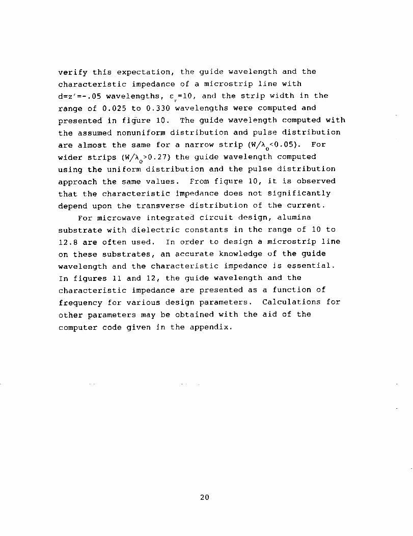
The geometry of a microstrip line embedded in a
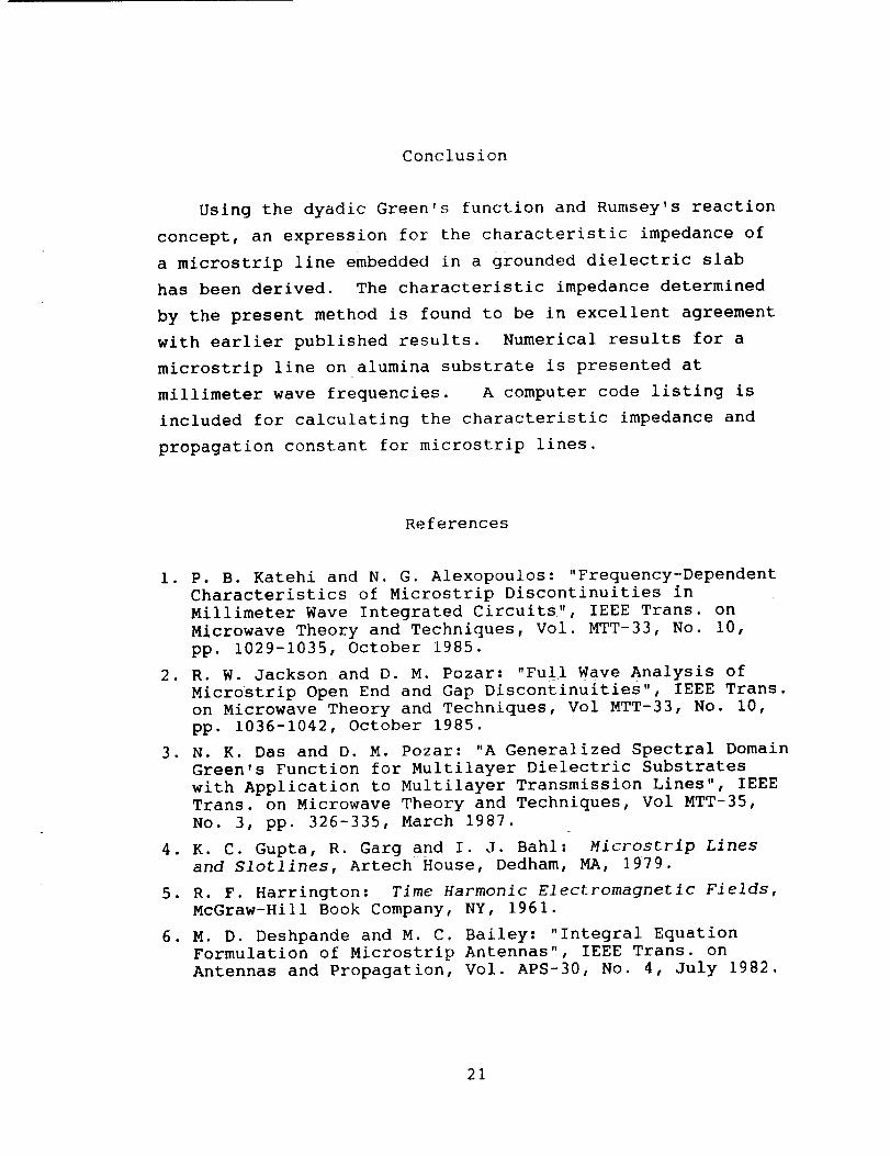
grounded dielectric slab is shown in figure 1 along withthe notation to be used. In order to determine the
characteristic impedance, consider a microstrip line being
excited by a current source backed by a perfect electricconductor at the x=0 plane, as shown in the current source
looks into a semi-infinite transmission line, the
characteristic impedance of the line would be the same as
the input impedance seen by the source. Assuming the strip
width, W, is much smaller than the operating wavelength,
the y-component of the strip current can be neglected. The
surface current, J(x,y), on the z=z' plane may then be
represented by
J(x,y) = xf(y) exp(-jK txl) -_-_x-_ (1 )
where K =B+j_ is the dominant mode propagation constante
along the strip. The range of x is extended to -_ due to
the image of the strip behind the conducting plane at x=0
and the magnitude of x is used to indicate propagation away
from the source at x=0. The transverse distribution, f(y),
in equation 1 may be assumed to be of the form
N
f(y) = _ I Pn(y ) (2)n= 1 n
where
Pn(y ) = i/Ay
=0
for (Yn- --_) -< y -_ (Yn + 2--_)
otherwi se.
From the continuity condition, the distribution f(y)
must satisfy
W/2
--W/ 2
f(y) dy = I° (3)
The pulse amplitudes, I , in equation 2 are determined,n
as explained later, by using the integral equation method
in conjunction with the method of moments.
If E(x,y,z) is the electric field due to the strip
current, J(x,y), then the input impedance seen by the
source is obtained from
W/2
1 J x,y • Ecx,y,z')dx dy (4)Z ln = Z 0 = 12
0 -W/2 0
This approach thus differs from the solution to the
multilayer transmission line problem [3], where the
characteristic impedance is obtained after dividing the
average voltage by the total current on the strip.
Furthermore, by taking into account the actual current
distribution in the y-direction, it is expected that the
present approach would give more accurate results. Using
the dyadic Green's function for a current embedded in a
grounded dielectric slab [6], the x-component of the
electric field E(x,y,z) is obtained as
x • E(x,y,z') =
CO 00
-Jnok0Z'
2k2 _ _ O(kx'ky) Jx (k× ,ky)(2n)
--CO --03
where,
• exp(jk×x+jkyy) dk dk× Y
(5)
O(kx,ky ) = (ke-kx_)_ (k×,ky) + jk_-_'2(k×,ky ) (6)
sin(k z')}_1(kx,ky) = (k z !)
cos(k (d-z')) + Ok sin(k (d-z'))]
ki 1 _i i
Ikicos(kid ) + jktlsin(k,d )
(7a)
N2 (kx,ky) _k2sin(kiz,) }I
erk_icos(kld) + jklsin(kld)
"{ sin(klz')(kz)
(cr_l)klcos(k,d ) + jk, isin(kid )
(7b)
kI
k2-k_-k 2 [k2+k 2] _< k2× y - x y-
-j/k_+k2-k 2 [k2+k e) > key " x y-
/k 2-k 2 _k 2
V 0 x y
kll = _j/k2+k2 k 2 'V _ Y 0
0
k2+k ] > k_x y" 0
In equation 5, _o is the free space characteristic
impedance, _I and g2 are derived in reference 6, and
Jx(k×'ky) is given by
W/2
j×(kx,ky ) : j" J" f(y) exp(-jKelxl-jkxx-jkyy ) dx dy
W/2 -co
(8)
From equations 2 and 8, and assuming a to be a finite
negative value, the integral in equation 8 may be evaluated
in closed form as
N [sin (k Ay/2)-J× (kx, ky ) - _ jI Y
n=l n (kyAy/2)
[_x l_Ke x_Ke]exp(-JkvYn), (9)
Substituting equation 5 into equation 4 and after some
mathematical manipulations, the characteristic impedance is
obtained as
ZO J_okoZl Nn_l _I o° °°{ Is,2.,2k2 2°f
I O -co -coin (ky Ay/2) ](kyAy/2)
-Kx
• $ (-k x -k ) exp(-jkyyn) } dk dkx ! y x y(I0)
where
W/2
A(-k'-k) ---W/ 2
co
_ f(y) exp(-jKex + JkxX + jkyy) dx dy
O
N
Z jim= I m
-sin (kyAy/2)
(kyAy/2)
[ex_p (jkyy m )
kx-Ke ](ii)
Substituting equation Ii into equation 10 gives
7
Z0
-JnokoZ" N N I I= Z Z n m
2
(2R) 2k 2 n=l m=l I o
--00 --CO
-sin(kyAy/2)
(kAy/2)
2
[ i i I-Ko k -Ko
Q(kx,ky ) exp(jkv(ym-yn) )} dk× dk Y(12)
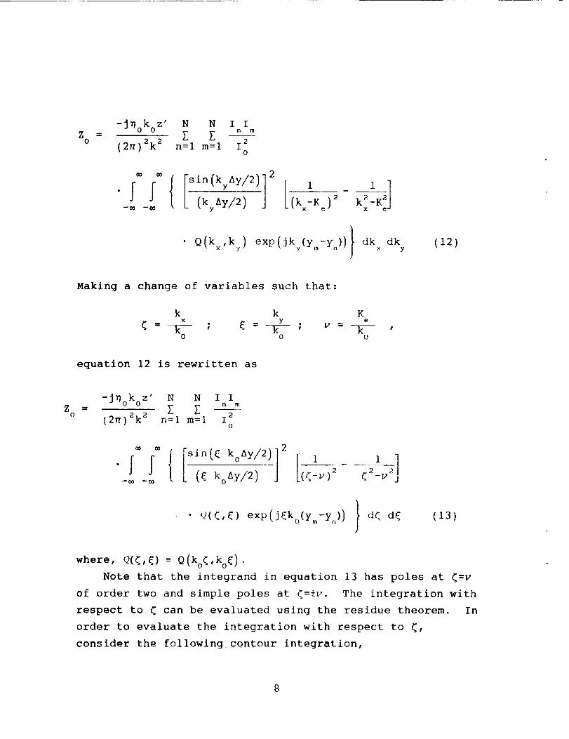
Making a change of variables such that:
k k K× y e
_ = k ; _- ]_ ; v =-_ ,0 0 o
equation 12 is rewritten as
Zo
-JDoko z' N N I In m
= Z Z(2n)Zk 2 n=l m--1 1 2
o
-m -m ([ koAy/2) (q-v) 2 <2-v2
• Q(<,{) exp(j_ko(ym-yn) ) } d< d_(13)
where, Q(_,_) m Q(ko_ ,ko_ ) .
Note that the integrand in equation 13 has poles at _=v
of order two and simple poles at _=±v. The integration with
respect to _ can be evaluated using the residue theorem. In
order to evaluate the integration with respect to _,
consider the following contour integration,
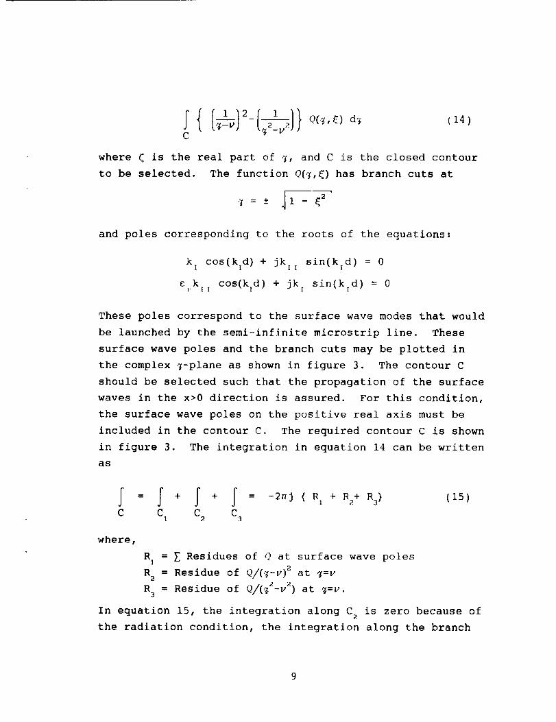
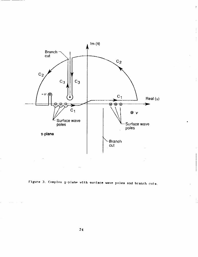
C
(14)
where _ is the real part of Z, and C is the closed contour
to be selected. The function O(_,_) has branch cuts at
_ = t 11 - _ 2
and poles corresponding to the roots of the equations:
k i cos(kld) + jk l,
crkll c°s(kld) + jk
sin(kld ) = 0
sin(kld ) = 0
These poles correspond to the surface wave modes that would
be launched by the semi-infinite microstrip line. These
surface wave poles and the branch cuts may be plotted in
the complex 7-plane as shown in figure 3. The contour C
should be selected such that the propagation of the surface
waves in the x>0 direction is assured. For this condition,
the surface wave poles on the positive real axis must be
included in the contour C. The required contour C is shown
in figure 3. The integration in equation 14 can be written
as
f f=+ + -2n9 ( RI 2 Ra) (15)
C C C CI 2 3
where,
R I = _ Residues of Q at surface wave poles
R2 = Residue of Q/(_-v) 2 at g=v
R 3 = Residue of Q/(_2-v2) at 7=u.
In equation 15, the integration along C2
is zero because of
the radiation condition, the integration along the branch
9
cut, C3, represents a radiation field, and the integration
along C I is the required integration to be evaluated with
respect to _. Since the radiation field due to the
microstrip line would be very small, the integration along
C 3 will be neglected. For the present case, the
contribution due to surface wave modes will also be
neglected. The integration with respect to < becomes
--00
<=v } (16)
Substituting equation 16 into equation 13, the expression
for Z reduces to0
-WokoZ' N N I In m
Zo= I2_k a n=l m=l I s
O
'2aQ(_,_) Q(<,_)
co
sin (ko Ay/2)
0
cos(_(m-n)koAY )} d_(17)
From the characteristic equation (27), it can be seen that
the term
N N
n=l m=l
co
I,,Im ] { O(('_)I o
0
" cos (((m-n)koAY) d(
(ko Ay/2)
in equation 17 is alway_ zero.
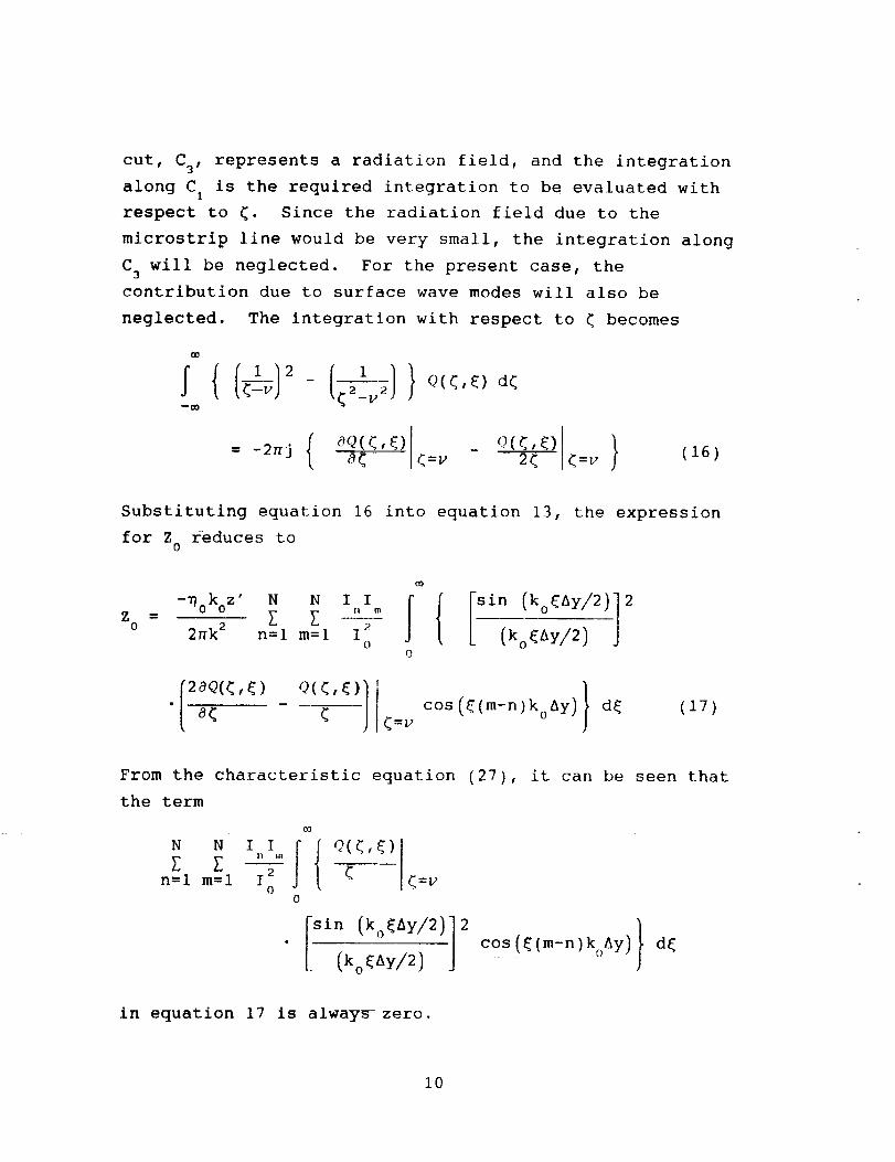
i0
For a uniform current distribution in the y-direction
(I =Io), the expression in equation 17 becomes
{ I ]}= d_ (_8)Zo ;_ ] o< _=_ (koOkY/2)
0
For a nonuniform current distribution of
21J(.w)f(y) = (19 )
/ 1 - (2y/W) 2
the characteristic impedance of the transmission line
becomes
o0
Zo = nk 2 a< <=v o
0
where Jo(. ) denotes the Bessel function of the first kind
of zero order.
11
Evaluation of K and Ic n
In order to determine K , consider the infinite
microstrip line as shown in figure i. The surface current
distribution on the strip may be assumed to be of the form
Jt(x,y) = x Jxt(X,y) = x f(y) exp(-jK x) -_-<x-_ (21)
where f(y) is as given in equation 2.
Using equation 8, the Fourier transform of Jt(x,y) is
obtained as
Jt(kx,ky) = X Jxt(kx,ky)
N [sin (kyAy/2)]= x [ 12,n= 1 . (kyAy/2)
" 6(kx+K ) exp(-jkyyn) (22)
where 6(.) is a delta function and is the result of
assuming a traveling wave current in the x-direction on the
strip as denoted by the exponential factor in equation 21.
The x-component of the electric field radiated by J×t
is obtained by replacing J×(kx,ky ) with Jxt(k×,ky) in
equation 5. Then by equating the x-component of the
electric field to zero on the surface of the strip, since
the total field must be zero and there is no incident
field, an electric field integral equation is obtained
12
-Jnok z' No [ I 2_
(2.)2k 2 n=l "
• (kyAy/2) j Q(k×,ky) 6(k×+Ke)m m_
exp(-jkyyn) exp(jk×x+jkyy)_ dk×i
)
dk (23)Y
By setting x=0 in equation 23 and selecting Pm(y ) as a
testing function and multiplying both sides of equation 23
by Pm(y ) yields
-JnokoZ' N0 = _ I 2_
(2.)2k _ n=l n
--_ --CO
-_in(kAy/2)]Q(k ,k) _(k+K )
• P (y) exp(-jk y_) exp(jkyy)} dkm y x
dk (24)Y
Integrating both sides of equation 24 with respect to y and
rearranging gives
jokozlN {[sinkyyJ2112_12k2 _ 12_f_n:l " -m -co (kyAy/2)
• Q(k×,ky) 6(kx+K ) exp(-jkyy_]
y +Ay/2 ] }mf Pm(y ) exp(jkyy) dy dk×
Ym -Ay/2
dk (25)Y
13
Using the property,
f(x) 8(x+x') dx = f(-x')
of a delta function, equation 25 can be written in the
form
-, okoz,. I0- £ i Q(k ,ky)2r_ k 2 nn= 1 k =-K
--CO x e
exp(-jky(Yn-ym) ) ',dkI y;
(26)
Since Q(kx,ky):Q(kx,-ky), equation 26 may be rewritten as
-jnoZ' Nr n=l n
O
"sin (_koAy/2)]cos (_koAy(m-n)) } d_
(27)
where _:k/k o, (:kx/k o, v=Ke/k o, and Q((,_)-O(ko(,ko{ ).
By selecting m=I,2,3 --- N, equation 27 may be written
in matrix form as
0
0
0 'd
Z Z .,. 71[ 12 13 1N
Z Z Z -.. f21 22 23 2N
Z f Z --. Z31 32 33 3N
Z Z /. ... ZN 1 N2 N3 NN
11
12
13
IN
(28)
14
where the components of the square matrix are given by
Zmn { i
0
-sin (_koAY/2)]
• cos((k0Ay(m-n)) } d_(29)
For a nontrivial solution of equation 28,-the determinant
of the square matrix in equation 28 must be set to zero,
therefore,
Z Z Z ... Z1 1 12 13 1N
Z Z Z • Z2 1 22 23 2N
Z Z Z --. Z3 1 32 33 3N
Z Z Z "." ZN 1 N2 N3 NN
0 (30)
Equation 30 is solved for K e in a numerical procedure
by selecting N and then starting with an estimate of K =ke
and iterating K until equation 30 is satisfied to thee
desired accuracy.
In order to determine the current distribution in the
transverse direction, it is assumed that the infinite
microstrlp line shown in figure 1 is excited by an
x-polarized plane wave. The surface current induced on the
strip may be assumed to be of the form
N
J(x,y) = x Jxu(X,y) = Z I Pn(y ) x (31)n= 1 n
If Exu(X,y,z) is the x-component of the scattered
electric field due to Jxu(X,y), and Ei(x'Y'Z)x is the
incident electric field, the boundary condition of zero
tangential electric field on the conducting strip gives
15
-EIx(x,y,z ') = E×u(x,y,z' )
Exu(X,y,z') can be obtained from equations 5,6 and 8.
Equation 32 then becomes
x,y,z')-- _k2 _ _ O(k, )(2n) n= I n k =0
--00 X
•[.sin(kyAy/2)(k_y/_)
exp(-jkyYn) } dky
(32)
(33)
Equation 33 is an integral equation with I as then
unknown complex values to be determined. Equation 33 can
be solved by selecting Pm(y ) as a testing function and
applying the method of moments to yield
N
I Z = - Ay Ei(z') for m=l,2,3,..-,N1
Z (34)= 1 n mn
u -
where E_(z') is the x-polarized plane-wave electri 9 field
incident on the strip from the z-direction (normal
incidence.) and Zmn is given by
-Jno k2z'o AyZ =
mn _
r
0
sin (_koAY/2)
(_koAY/2)cos(_(m-n)koAY )} d E
(35)
Equation 34 can be written in matrix notation as
16
11
12
13
I
Z Z Z -'- Z11 12 13 1N
Z21 Z22 Z23''" Z2.
Z31 Z32 Z33"'" Z3.
Z.i Z_2 Z.3''" Z.N
-Ay E io
-Ay E i0
-Ay E l0
(36)
and the complex values of I are obtained by matrix
inversion.
17
Numerical Results
In order to obtain numerical results, the semi-infinite
integrals appearing in equations 17, 18, 20, 29 and 35 are
evaluated using Gauss Quadrature integration techniques and
the upper limit on the integration is truncated to a large
finite value. From numerical results, it was found that
the upper limit on the integration depended upon frequency
and could vary from t=200 (for high frequencies) to t_1000
(for frequencies below 5 GHz). Because of the complexity
of the expression for Q(kx,k) , the derivative, aQ/ak ory x
aQ/a_, is evaluated numerically.
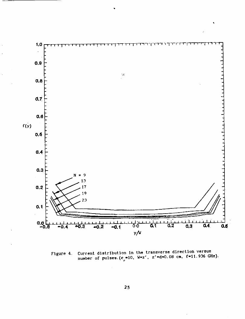
In order to obtain meaningful numerical results, it is
desirable to apply convergence tests to I , K and Z . Then _ 0
matrix equation is solved for I for various values of Nn
and plotted in figure 4. It is observed that a stable
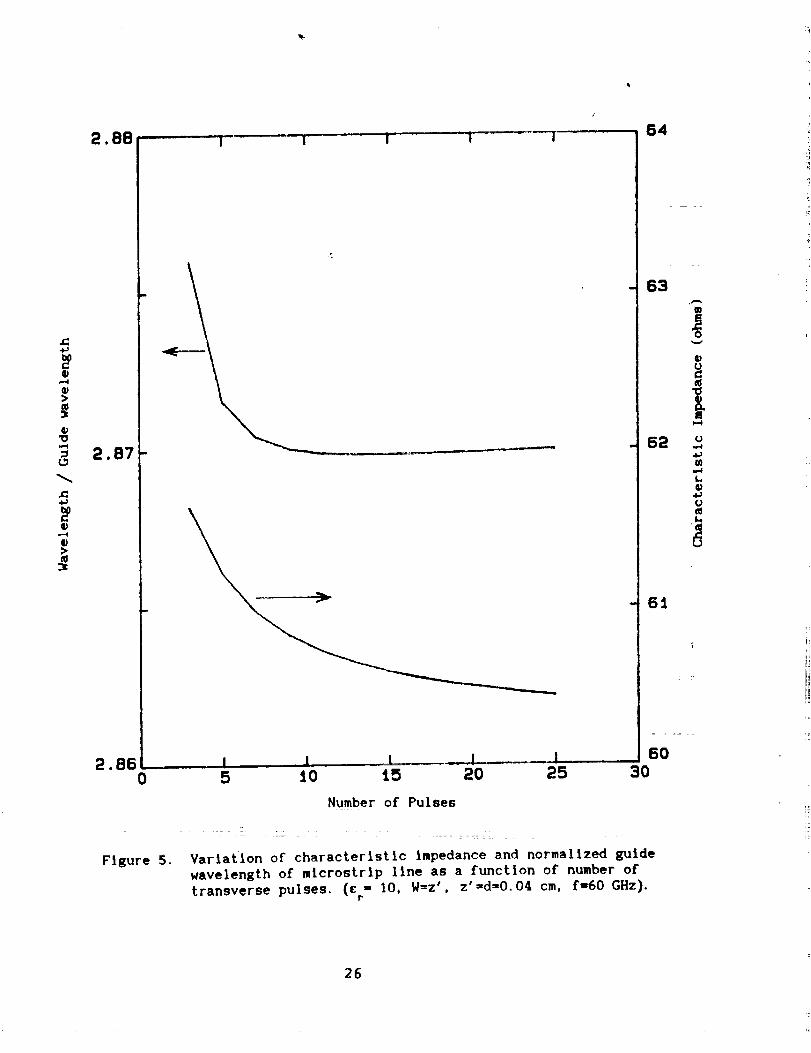
solution for I is obtained when Na25. Figure 5 shows then
variation of K and Z as a function of N. It is notede 0
that Na25 also gives converged values for these quantities.
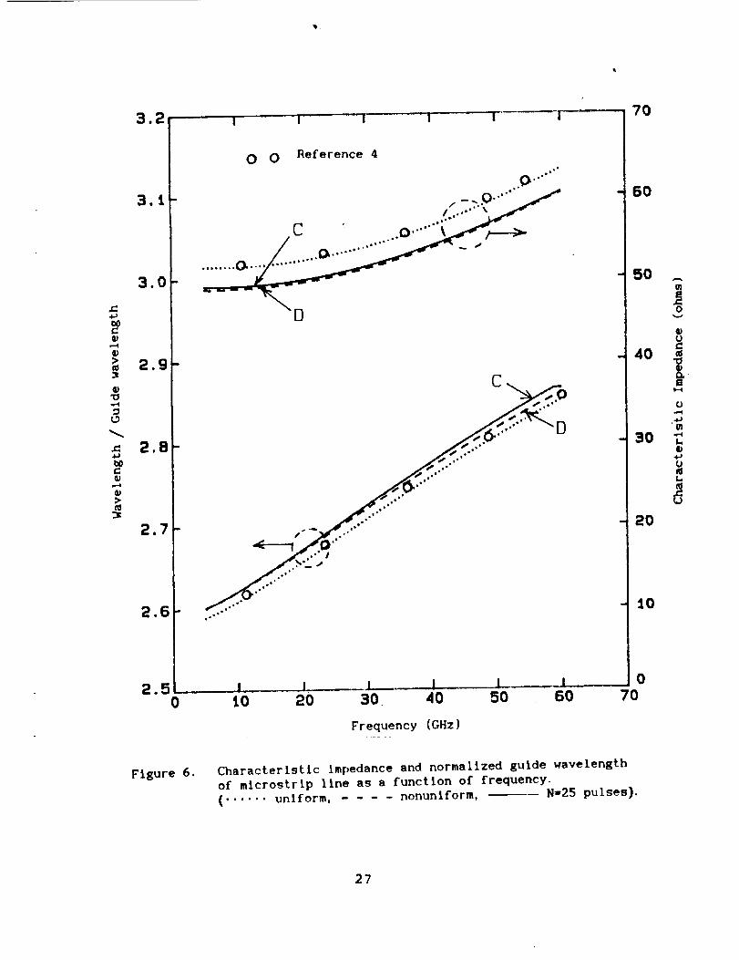
To verify the present formulation, the characteristic
impedance and the guide wavelength of a microstrip line
with W/z'=l.O, d=z'=-.04 cm, and e =i0, is computed using
equations 13 and 22 for N=25. These results are presented
in figure 6 as a function of frequency along with results
reported earlier [5]. Using the present method, Z ° and K e
are also computed for uniform current distribution and
nonuniform (see eq.14) current distributions and presented
in figure 6. The results obtained by the present method
with uniform distribution are in excellent agreement with
the results reported earlier [4]. However, Z ° and K e
calculated by taking into account the actual current
distribution (as obtained from equation 36) is believed to
give more accurate results than the results obtained with
18
uniform current distribution. It is also observed from
curves C & D of figure 6, that the assumed nonuniform
distribution is close to the actual calculated current
distribution and may be used instead of the pulse
distribution in order to save computation time. To compare
the present method with the approach in reference 3, the
characteristic impedance of a microstrip line with d=z" and
d=4z ', e =2.53, f =3GHz is computed as a function of stripr o
width, W/z', and presented in figures 7 and 8. It is noted
that there is a small discrepancy between the two results
in figure 8. This may be attributed to the different type
of current distribution assumed in the two cases. With an
assumption of uniform current distribution in the
y-direction, the results obtained by the present method are
also presented in figure 7. There is good agreement
between the results obtained by the two methods. Figure 8
shows the characteristic impedance of a microstrip line
covered with a dielectric slab.
The results obtained by the present method are also
compared in figure 9 with data taken from reference i. For
frequencies greater than 42 GHz, the dielectric thickness
becomes greater than a quarter-wavelength and the current
distribution in the y-direction may not be of the assumed
form. Furthermore, for thicknesses greater than a
quarter-wavelength, the microstrip line would act as a
radiator rather than a transmission line.
It is interesting to study the effect of distribution
in the y-direction on the guide wavelength and the
characteristic impedance of a microstrip line. It is
expected that for a narrow strip, the distribution may be
closer to the assumed nonuniform function (equation 19);
whereas, for a wider strip, the distribution is expected to
be closer to uniform, except near the strip edges. To
19
verify this expectation, the guide wavelength and thecharacteristic impedance of a microstrip line with
d=z'=-.05 wavelengths, c =i0, and the strip width in theF
range of 0.025 to 0.330 wavelengths were computed and
presented in figure i0. The guide wavelength computed with
the assumed nonuniform distribution and pulse distribution
are almost the same for a narrow strip (W/lo<0.05). For
wider strips (W/A0>0.27) the guide wavelength computed
using the uniform distribution and the pulse distribution
approach the same values. From figure 10, it is observed
that the characteristic impedance does not significantly
depend upon the transverse distribution of the current.
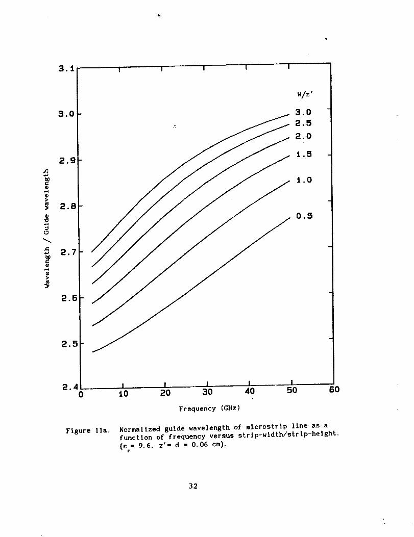
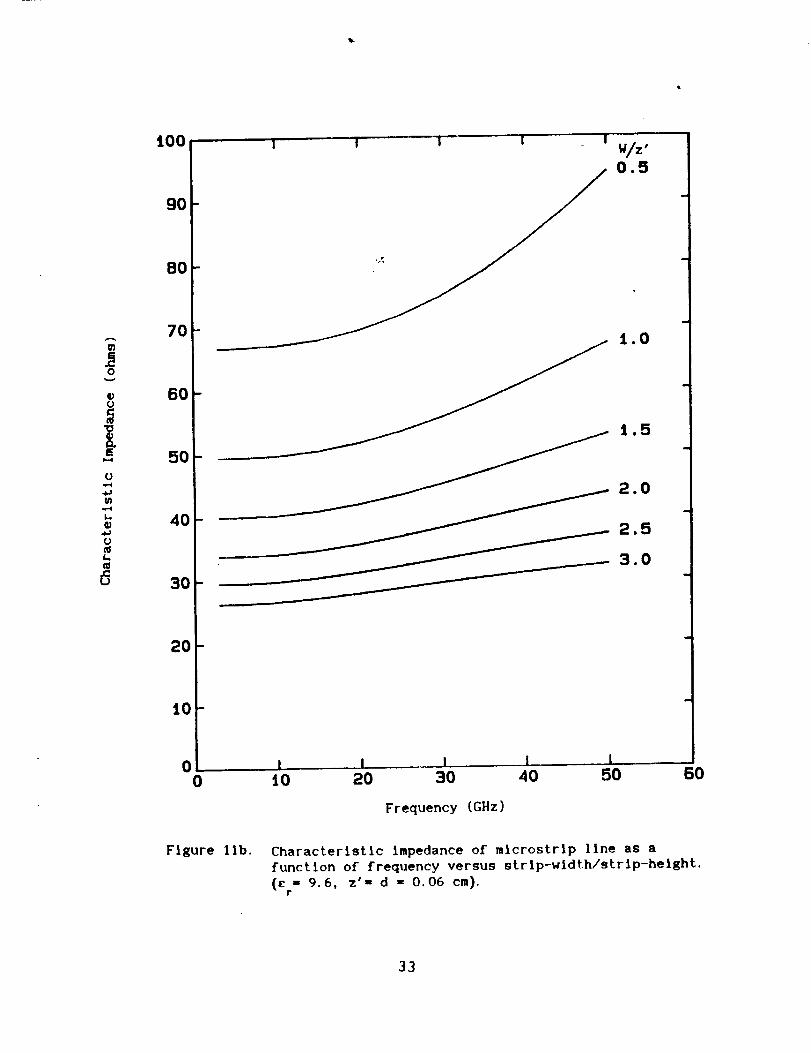
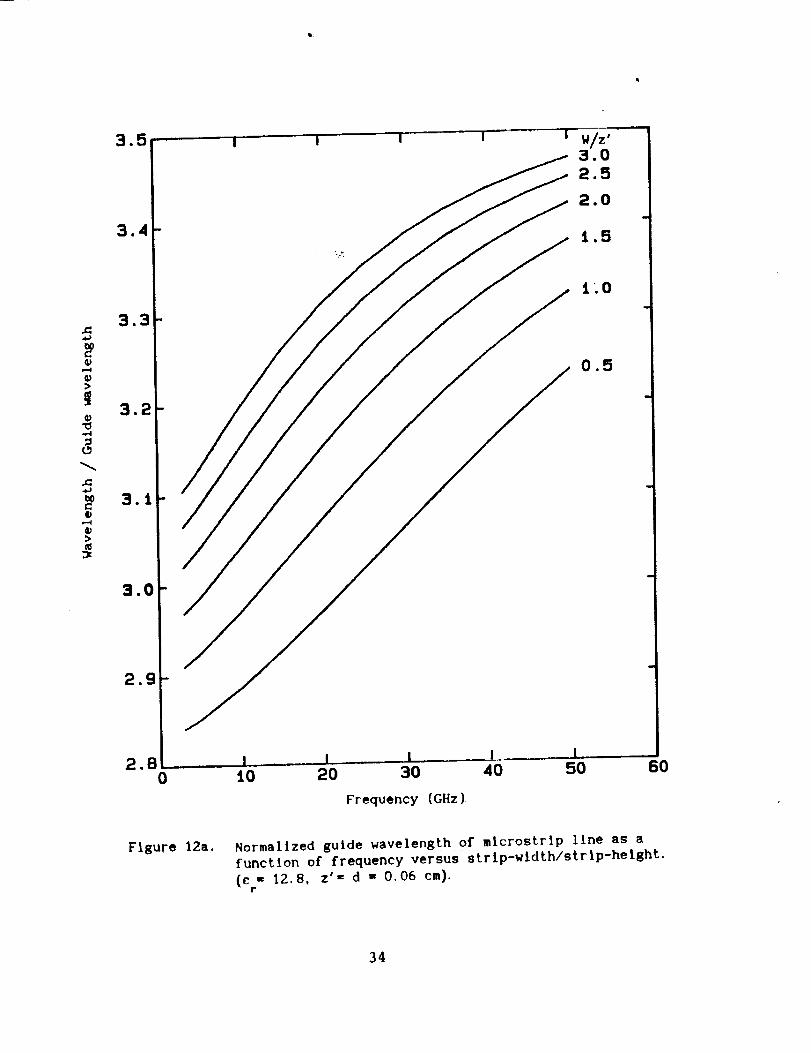
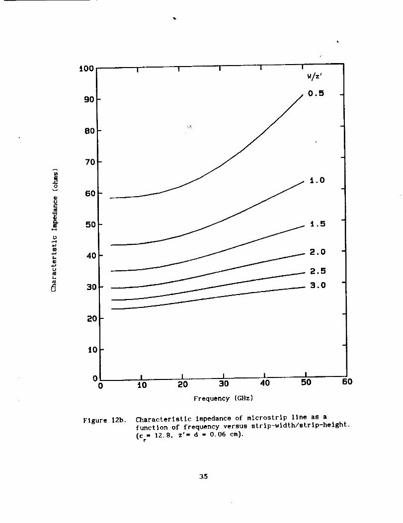
For microwave integrated circuit design, alumina
substrata with dielectric constants in the range of 10 to
12.8 are often used. In order to design a microstrip line
on these substrates, an accurate knowledge of the guide
wavelength and the characteristic impedance is essential.
In figures ii and 12, the guide wavelength and the
characteristic impedance are presented as a function of
frequency for various design parameters. Calculations for
other parameters may be obtained with the aid of the
computer code given in the appendix.
20
Conclusion
Using the dyadic Green's function and Rumsey's reaction
concept, an expression for the characteristic impedance of
a microstrip line embedded in a grounded dielectric slab
has been derived. The characteristic impedance determined
by the present method is found to be in excellent agreement
with earlier published results. Numerical results for a
microstrip line on alumina substrate is presented at
millimeter wave frequencies. A computer code listing is
included for calculating the characteristic impedance and
propagation constant for microstrip lines.
References
I. P. B. Katehi and N. G. Alexopoulos: "Frequency-DependentCharacteristics of Microstrip Discontinuities inMillimeter Wave Integrated Circuits", IEEE Trans. onMicrowave Theory and Techniques, Vol. MTT-33, No. i0,pp. 1029-1035, October 1985.
2. R. W. Jackson and D. M. Pozar: "Full Wave Analysis ofMicrostrip Open End and Gap Discontinuities", IEEE Trans.on Microwave Theory and Techniques, Vol MTT-33, No. 10,pp. 1036-1042, October 1985.
3. N. K. Das and D. M. Pozar: "A Generalized Spectral Domain
Green's Function for Multilayer Dielectric Substrates
with Application to Multilayer Transmission Lines", IEEE
Trans. on Microwave Theory and Techniques, Vol MTT-35,
No. 3, pp. 326-335, March 1987.
4. K. C. Gupta, R. Garg and I. J. Bahl: Microstrlp Lines
and Slotlines, Artech House, Dedham, MA, 1979.
5. R. F. Harrington: Time Harmonic Electromagnetic Fields,
McGraw-Hill Book Company, NY, 1961.
6. M. D. Deshpande and M. C. Bailey: "Integral Equation
Formulation of Microstrip Antennas", IEEE Trans. on
Antennas and Propagation, Vol. APS-30, No. 4, July 1982.
21
d Z• P •
Microstrlp Line
/
l
t
/
Ground Plane
Figure I. Geometry of mlcrostrip Line.
22
F
Perfect Electric Conductor
Ground Plane
Flsure 2. Current source exciting microstrlp line.
23
Branchcut I
Im (_)
C2
C2
C3 C3
_-plane
CI
Surface wavepoles
C 1 Real (,_)
- Surface wave
poles
_- Branch
cut
Figure 3, Complex v-plane wlth surface wave poles and branch cuts.
24
r(y)
o.8
N=9
13
17
19
23
Figure 4. Current distribution In the transverse direction versus
number of pulses.(e -10, W=z', z'=d=O.08 cm, f-11.936 GHz).r
25
J_4J
@
@>
@_0
0
4J
@
@
2.88
2.B7
2.86
i :- " I* I .... -_i i
0I J _ ...... ! !5 10 15 20 25
Number of Pulses
64
63
Figure 5. Variatlon of characteristic impedance and normallzed guide
wavelength of mtcrostrlp llne as a function of number oftrangverse pulses. (e = 10, W=z', z'=d=O.04 cm, f=60 GHz).
P
m
o
¢J
k-4
¢J
.bJ
,,-4
¢,@
4J¢J
- 62
- 61
6030
26
X:
a),-4
a)
i)
.,4
L9
4J
G),-4
Q)>
3=
3.t
3,0-
2.9-
2,8-
2.7-
2.6
2.50
Figure 6.
0 0 Reference 4
D
I I I i ! !
lO 20 30 40 50 60
Frequency (GHz)
7O
- 60
- 50
- 40
30
- 20
- lO
0rO
Characteristic impedance and normalized guide wavelength
of mlcrostrip line as a function of frequency.
( ...... uniform, - - - - nonuniform, N=25 pulses).
w
ml-4
0.,4
4J
.,d
I.
4-)
U
L
27
150
125
IO00
J=
U
r,..,
u
L.
75-
50
25 -
0
0
I I I I I
Present Method (nonuniform)-Present Method {uniform)
Reference 3
! 1 l 1 I ,
1 2 3 4 5 6
W//Z o
Figure 7. Characteristic ilmpedance of covered mlcrostrip llne.
(d = 0.64 cm, z'= 0.16 cm, c = 2.53, f = 3 GHz).r
28
o
U
iJi
U
t_
I,,,,
0
L.
d
150 ,
125 -
100 -
75-
50-
25-
00
I I I I I
Present Method (nonuniform)Reference 3
"\
.1 I I I, i1 2 3 4 5
_Z J
6
Figure 8.Characteristic Impedance of mlcrostrtp line.(z'= d = 0.16 ce, e = 2.53, f = 3 GHz).
r
29
J=
p=d
>
_J
e.4J
,=d
>
3.3
3.2
3.!
3.0
2.g "
2.8-
2.7-
2.6
2.50
Figure 9.
.... i j j '| w
0 0 Reference I ..f
fT"
IB I
oe,loe _" , 16e°_° o- °°_°el°'ll''jl
a,I Qa
.._...-'"
,I _1___- _ , i .... I ! 0t0 20 30 40 50 60
BO
7O
6O
50 ®
t
40 u
m
4)
U
L.
20
iO
Frequency (GHz)
Characteristic Impedance and normalized guide wavelength
of mlcrostrIp llne as a function of frequency.
(c - 9.6, W = z', z'= d- 0.6 cm}P
(...... uniform, nonuniform, N=25 pulses).
3O
4_
bO
>
_O
L_
3.10i
3.05
3.00
2. g5
2. go
2.85 -
2.80
2.75
2.70 -
2.65
2.60 ....0.00
I
(
u i " u ! u t00
- 9O
- 8O
- 7O
60
5O
4O
3O
- 2O
- tO
I I i I ,I I.. _0O. 05 O. 10 O. i5 O. 20 O. 25 O. 30 O. 35
Strip width / Wavelensth
Figure 10. Characteristic impedance and normalized guide wavelengthof microstrip line as a function of strip width.
(c- lo, z'= d - O. OS _)r
( ...... uniform, - .... nonuniform, N=25 pulses).
¢/I
0
0
o
0
e_
e_
31
3.!
3.0
2.g
2.8
i 2.7
2.6
2.5
I I I ! I
3.0
2.5
2.0
1.5
2.4 l t I I.. I
0 t0 20 30 40 50 60
Frequency (GHz)
Figure fla. Normalized guide wavelength of mlcrostrip line as a
function of frequency versus strip-width�strip-height.
(e = 9.6, z'= d = 0.06 cm).
32
IO0
9O
80
,0_ 60
5O
40
_ 3o
2O
10
i t 1 i ww/.,0.5
t.O
1.5
2.0
2.5
3.0
0 1 I I 1 I0 t0 20 30 40 50 60
Frequency (GHz)
Figure llb. Characteristic impedance of mlcrostrlp llne as a
function of frequency versus strtp-wldth/strlp-height.
(c = 9.6, z'= d = 0.06 cm).r
33
@,--4
"o
,-4
>
2.B0
I
i Jt0 20 30 40 50 60
Frequency (GHz)
Figure 12a. Normalized guide wavelength of microstrlp llne as a
function of frequency versus strlp-wldth/strlp-helght.
(c = 12.8, z '= d = 0.06 cm).r
34
t00
90
BO
70
4, 60
_ 3o
2O
iO-
00
I I I I I
N/z '
0.5
i.O
- i.5 "
2.0 "
2.5
3.0 -
I I I I IiO 20 30 40 50 60
Frequency (GHz}
Figure 12b. Characteristic impedance of mlcrostrlp llne as a
function of frequency versus strlp-wldth/strlp-helght.
(c = 12.8, z'= d = 0.06 cm).r
3,5
Appendix
Instruction for us!ng computer code
The main program HSTRIP. FOR calculates the characteristic
impedance, Zo, and the dominant mode propagation constant, K_, of
a microstrlp llne embedded in a grounded dielectric slab.
The main program must be linked to the following subroutines:
ZTEMP. FOR
SRMN. FOR
MATINV. FOR
MATROW. FOR
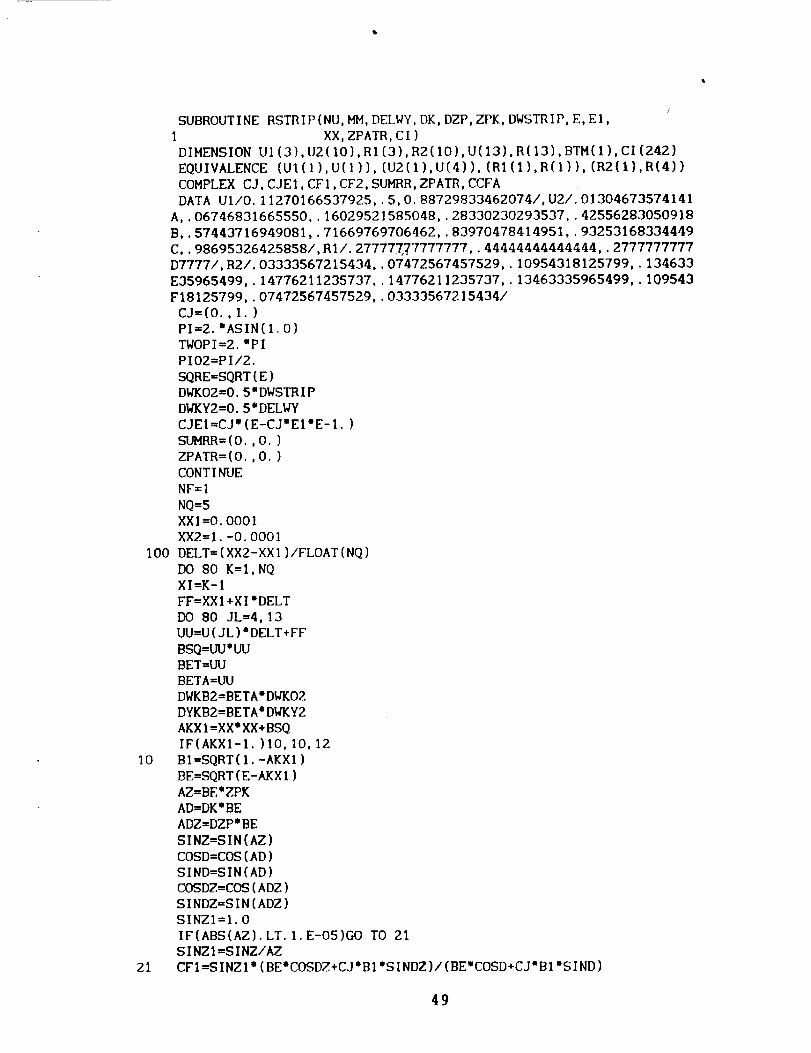
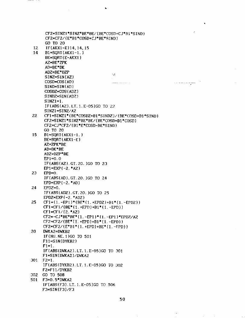
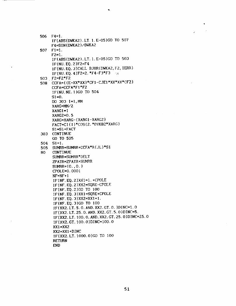
RSTRIPI.FOR
RSTRIP. FOR
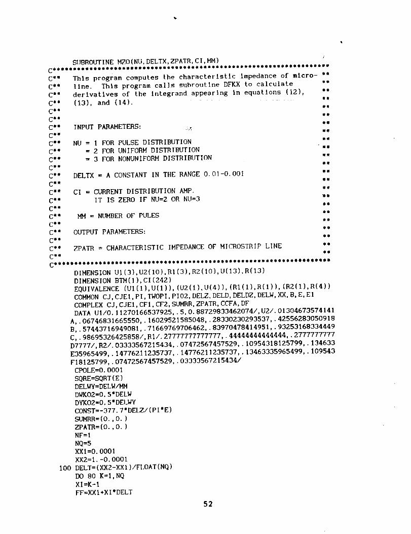
I'-rZO. FOR
DFKX. FOR
INPUT DATA :
NU = Integer selecting the type of current distribution.
I for pulse distribution.
2 for uniform distribution.
3 for nonuniform distribution.
= Number of pulses assumed in the pulse distribution.
(maximum number = 242).
ED _ Dielectric slab thickness In free space wavelengths.
EZP = Height of strip above ground plane in free space
wavelengths.
Dielectric constant or slab.
= Loss tangent of dielectric slab material.
= Minimum mlcrostrip width in free space wavelengths.
= Maximum mlcrostrlp widlh in free space wavelengths.
For pulse distribution, the transverse current distribution is
output to file FOROIO. DAT.
The characterlstlc impedance and domlnant mode propagatlon
constant as a function or mlcrostrlp width are output to file
FOROI3. DAT.
MM
E
El
WSTR IP
WMAX
36
BRIEF OUT_IN_ OF METHOD :
The current distribution is assumed In the form;
Jx( x, y) = f(y) exp(-JK x)
a ,(x,y) = o.y
For the above current dlstributlonl the program calculates the
dominant mode propagation constant:_nd the characteristic
Impedance /or one of three cases:
f(y) = Io/44 (uniform)
21
f(y) = o (nonuniform)
,wV 1 - (2y/w)
f(y) = InPn(y ) n=I,2,...,MM (pulses).
For the distributions, the program calculates the K first bye
calling subroutine RSTRIPI. The subroutine RSTRIP1 solves
equation 27 for K . RSTRIP1 uses standard technique to find zerose
of a polynomial..
For the pulse distribution, the main program solves the matrix
equation Eiven in equation 36. This is done by computing mutual
impedances by calling subroutine SRMN. The mutual impedance
matrix is inverted using MATINV. I are found using HATROW.N
Equation 28 is then solved for K by using subroutine RSTRIP1.@
The characteristic Impedance for either distribution is computed
by calling subroutine HZO.
37
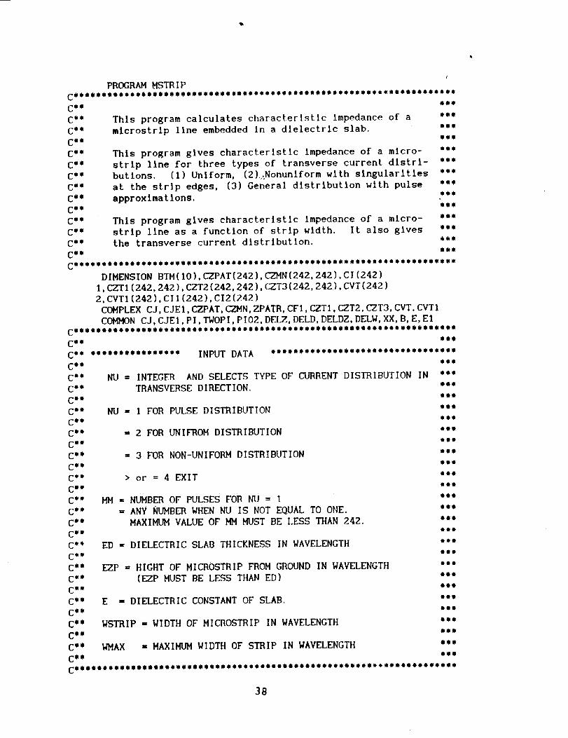
PROGRAM MSTRIP
CO_ejooooemooi_o_llo,o_oool,o,mee_ooeomoooo_o*oomoe_oe_oo_oleloloee_
Cm o foe
C'" This program calculates characterlstLc Impedance of a **m
C** microstrlp line embedded In a dielectric slab. "'*
C_ e iol
C °" This program gives characteristic impedance of a micro- "'"
C ee strip llne for three types of transverse current distrl- .oo
C*" butions. (I) Uniform, (2)_Nonunlform with singularities "''
C'" at the strip edges, (3) General distribution with pulse ,m,
C o" approximations. ,,o
CO e mee
C'" This program gives characteristic impedance of a micro- eom
C ml strip line as a function of strip width. It also gives '*"C "° the transverse current distribution. _oo
Ce I I@e
DIMENSION BTM(IO),CZPAT(242),CZMN(242,242),CI(242)
I,CZTI(242,242),CZT2(242,242),CZT3(242,242),CVT(242)
2,CVT1(242),CI1(242),CI2(242)COMPLEX CJ,CJEI,L-ZPAT, CZMN,ZPATR, CFI,CZT1,CZT2,C-ZT3, CVT, CVTI
COMMON C J,C JEt, PI, TWOPI, PI02, DELZ, DELD, DELDZ, DELW, XX, B, E, El
CmeOemoeeeeemeo_eeoeomeomoeomo_eoeooQeeee_mmeooeo omeeOoeeeomemeee'Q_
CO e eom
Ce, emem,moee_mm,,,, INPUT DATA ,,,ememm,emmeemmmmme,mmm_em_mmm_m
C_ e eee
C_ _ _I
C_ "_m
C_ _ ml_
Co m m_m
C_ _ _
C_, _m
C_ _ ,_I
C_ _
Cm _ _"
C_ _ _
C, _ ml_
C_ _
Cm e eee
Cm e eee
C_ 0 OmO
C_ _
Ce m mee
C_ O ,me
C'' "''
NU = INTEGER AND SELECTS TYPE OF CI/RRENT DISTRIBUTION IN
TRANSVERSE DIRECTION.
NU = I FOR PULSE DISTRIBUTION
= 2 FOR UNIFROM DISTRIBUTION
= 3 FOR NON-UNIFORM DISTRIBUTION
> or = 4 EXIT
MM = NUMBER OF PULSES FOR NU = I
= ANY NUMBER WHEN NU IS NOT EQUAL TO ONE.
MAXIMUM VALUE OF MM MUST BE LESS THAN 242.
ED = DIELECTRIC SLAB THICKNESS IN WAVELENGTH
EZP = HIGHT OF MICROSTRIP FROM GROUND IN WAVELENGTH
(F_.ZPMUST BE LESS THAN ED)
E = DIELECTRIC CONSTANT OF SLAB.
WSTRIP = WIDTH OF MICROSTRIP IN WAVELENGTH
WMAX = MAXIMUM WIDTH OF STRIP IN WAVELENGTH
38
WRITE(5,') 'GIVE THEVALUEOFNU'WRITE(S,')'FOR PULSEDISTRIBUTIONNU=I,
INU=2, FORNONUNIFORMDISTRIBUTIONNU=3,READ(5,')NUWRITE(5,')'GIVE THEVALUEOFMM'WRITE(5,')'MM = I TO242'READ(5,')MMWRITE(5,')'GIVE THEVALUEOFDILECTRICSLABTHICKNESS1 IN WAVELENGTH' .z
READ(5,')ED
WRITE(5,')'GIVE THE POSTION OF STRIP FROM GROUND IN
I WAVELENGTH'
READ(5,')EZP
WRITE(5,')'GIVE DIELECTRIC CONSTANT AND LOSS TANGENT
I OF SLAB MATERIAL'
READ(5,')E, EI
WRITE(5,')'GIVE STRIP WIDTH, MAXIMUM STRIP WIDTII IN
I WAVELENGTH'
READ(5,')WSTRIP,WMAX
IF(NU. GT. 3)GO TO 105
DELTX=O. O01
CJ=(O.,1.)PI=2.'ASIN(1.O)
PIO2=PIIO. 5
TWOPI=2.°PI
CJEI=CJ'(E-CJ*E*EI-I.)
SQRE=SQRT(E)
WRITE(13,')'CHARACTERISTIC IMPEDANCE, PROPAGATION CONSTANT'
WRITE(13,*)' OF MICROSTRIP LINE
WRITE(13,')'SLAB THICKNESS ED = ',ED
WRITE(13,*)'POSITION OF STRIP EZP =',EZP
IF(NU. EQ.I)WRITE(13,')'DISTRIBUTION PULSE WITH MM =',MM
IF(NU. EQ.2)WRITE(13,')'UNIFORM DISTRIBUTION'
IF(NU. EQ.3)WRITE(13,')'NONUNIFORM DISTRIBUTION'
WRITE(13,')'''STRIPWIDTH'",'''PROPAGATION CONST. _'', '''IMP.'"
103 DELD=TWOPI'ED
DELZ=TWOPI'EZP
DELW=TWOPI'WSTRIP
DELDZ=DELD-DELZ
DELWY=DELW/MM
B=O
CQ " ommo
C'" If dielectric constant of the slab = I "'""
C'" then avoid surface wave calculation. ,,m_
COm i,_,
COmOoeoI_o_ooleo_leo,oloeo_omo_*,,,o_e,ee,oleo,oom*o_o_o*QoBt,I
IF(E. EQ.I.)GO TO 501
NE=I
NNMAX=I
CALL ZTEMP(BTM, NE, NNMAX, E, DELD)
B=BTH ( ! )
FOR UNIFORM DISTRIBUTION
NU GREATER THAN 3 EXIT.'
39
COO.oo._oeo..,ooQ,o_o_eooooooooo..o_oo.moeoooo_omo.,oo.oooo,o. 0 ,"
C_ m mom
C"° If NU = I calculate mutual impedance matrix using *'"
C'' subroutine SRMN. When NU not equal to I mutual ''"
C"i matrix is not required. "'"
C'" mmm
C"'""'''''''"'"***'*"'*'""'"***"*'*''*''"****''""'*''''''''"
IF(NU. NE.I)GO TO 502
501 CALL SRMN(MM, CZPAT) =_DO 10 I=I,MM
DO 10 J=I,MM
IF(J. LT.I)GO TO 10
CZMN(I,J)=CZPAT(J-I+I)
I0 CONTINUE
DO 20 I=I,MM
DO 20 J=l,MMIF(J. LE.I)GO TO 20CZ_4N(J,I)=CZMN(I,J)
20 CONTINUE
DO 30 I=I,MM
DO 30 J=I,MM
CZTI(I,J)=CZMN(I,J)30 CONTINUE
EDK=SQRE'DELZ
DKK=SQREIDELDCFI=2.'CJ'SIN(EDK)'CEXP(CJ'DELZ)/(SQRE'COS(DKK)+CJ'SIN(DKK))
DO 50 I=I,MM
CVT(1)=-CFI
5O CONTINUE
CALL MATINV(CZTI,MM, CZT2)
CALL MATROW(CZT2,MM, CVT, CVTI)
SI=O.
DO 301 I=I,MMFACT=CABS(CVTi(1))
SI=SI+FACT
301 CONTINUE
DO 302 I=I,MMCVTI(1)=CVTI(1)/SI
302 CONTINUE
DO 303 I=I,MMCI(I)=CABS(CVTI(1))
303 CONTINUECm_ie_oo*ooe,m_om.o*.Qo.o_ooomm,ooomm_o..,,o. O'."'"'_""""Om_''"'O0''
C_ "_"
C'" CI(1) is the current distribution in the transverse direction ''°
CO , ,co
CeeOee.oee,,eee,eooeeoeo.oeeeo...ee.*oooe6oooee,oe. ''','eee_eeOeeoe'e"
WRITE(IO,') 'TRANSVERSE CURRENT DISTRIBUTION'
WRITE(IO,") '''"'"" Y/W ""''",''''''""CURRENT AMP.'''"
DO 304 I=I,MMDWY=(2"I-I)
DWY=DWY'DELWY'O.5/DELW
WRITE(IO,')DWY, CI(1)
304 CONTINUE
40
C_WWeemewoweWewmemeewweww4ww_emeeoeoe,_QwoewmwowmoweewwewmowoQewOee_
C '° The transverse current distribution calculation for NU =1 e,,
C'" is completed here. The CI(1) as a function of DWY is ,.o
C'" outputted at FOROIO. DAT file. The C[(1) is not computed "'"
C'" when NU Is not equal to one. "_"COm ooo
502 NNMAX=I
C'" "''"
C'" For the current distribution CI(1) the SUBROUTINE RSTR|PI "&'"
C'" calculates dominant mode propagation cons%ant for the micro- "
C'" strip llne. "''"
C "° RSTRIP1 solves equat|on (17) for Ke. _,o,
C'" RSTRIPI must be linked to RTSRIP SUBROUTINUE "''"
CO. oooo
CALL RSTRIPI(NU, NNMAX, MM, DELWY, DELD, DELDZ, DELZ, DELW,
IE, EI,BTM, CI)
XX=BTM(1)
CALL MZO(NU, DELTX, ZPATR, CI,MM)
WRITE(13,')WSTRIP, XX, ZPATR
WSTRIP=WSTRIP+O. O05
IF(WSTRIP°GT. WMAX)GO TO 104
GO TO 103
105 WRITE(5,') 'CURRENT DISTRIBUTION NOT SELECTED PROPERLY'104 STOP
END
41
%,.
I0
12
13
14
1S
16
17
SUBROUTINE ZTEMP(BTM, NE, MAX, E, DK)
DIMENSION BTM(1)
SQRE:SQRT(E)
DELTA:O.I
BI=I.O
BR=I.O+DELTA
IF(B2. GT.SQRE)B2=SQRE
BT:B2
N=O
DI:SQRT(E-BI'BI) ....
DKI=DK*DI
SI=SIN(DKI)CI=COS(DKI)
FI=E*SQRT(BIOBI-I.O),CI-DI,SI
D2=SQRT(ABS(E-B2"B2))DK2=DK'D2
S2:SIN(DK2)
C2=COS(DK2)
F2=E_SQRT(B2,B2-1.0)'C2-D2"S2
FT=F2
IF(FI.LT.O.O. AND. F2. LT.O.O) GO TO
IF(FI.GT.O.O. AND. F2.GT.O.O) GO TO
AFI=ABS(FI)
AF2=ABS(F2)
BP=BI+(B2-BI)'AFI/(AFI+AF2)
IF(ABS(B2-BI).LE.I.E-04) GO TO 14
DP=SQRT(E-BP°BP)
DKP=DK'DP
SP:SIN(DKP)
CP:COS(DKP)
FP=E'SQRT(BP'BP-I.O)'CP-DP'SP
IF(ABS(FP).LE.I.E-04) GO TO
IF(FI.LT.O.O. AND. FP. LT.O.O)
IF(FI.GT.O.O. AND. FP. GT.O.O)
B2=BP
F2=FP
GO TO 12BI=BP
FI =FP
GO TO 12
N=N+I
IF(N.GT. HAX) GO TO ]7
BTM (N )=BP
BI=BT
IF(ABS(BI-SQRE).LE.I.E-O5) GO TO 16
B2=BI+DELTA
IF(B2. GT. SQRE)B2=SQREBT=B2
GO TO I0
NE=N
RETURN
END
15
15
14
GO TO 13
GO TO 13
42
SUBROUTINE SRMN(MM, ZPATR)
DIMENSION U1(3),U2(10),RI(3),RZ(10),U(13),R(13)
DIMENSION BTM(1),SU_R(242),ZPATR(242)
EQUIVALENCE (UI(1),U(1)),(U2(1),U{4)),(RI(1),R(1)),(R2(1),R(4))
COMMON CJ, CJEI,PI,TWOPI,PIO2, DELZ, DELD, DELDZ, DELW, XX, B,E, EI
COMPLEX CJ, CJEI,CFI,SUMRR,ZPATR, CCFA
DATA UI/O. IIZ70166537925,.5,0. BB729833462074/,U2/.OI304673574141
A,.06746831665550,.16029521585048,.28330230293537,.42556283050918
B,.57443716949081,.7166976970_462,.83970478414951,.93253168334449
C,.98695326425858/,RI/.27777777777777,.44444444444444,.2777777777
D7777/,R2/.03333567215434,.07472567457529,.10954318125799,.13_633
E35965499,.14776211235737,.14776211235737,.13463335965499,.109543
F18125799,.07472567457529,.03333567215434/
DELWY=DELW/MM
SQRE=SQRT(E)
DWKO2=O. 5"DELWY
CONST=377.7"DELZ'DELWY/PI
DO 201 I=I,MM
SL_R(1)=(O.,O.)
ZPATR(1)=(O.,O.)
201 CONTINUE
NF=I
NQ=5
XXI=O. O001
XX2=l.-O. O00l
I00 DELT=(XX2-XXI)/FLOAT(NQ)
DO 80 K=I,NQ
XI=K-I
FF=XXI+XI'DELT
DO 80 3L=4,13
UU=U(JL)'DELT+FF
BSQ=UU'UU
BET=UU
BETA=UU
DWKB2=BETA'DWK02
AKXI=BSQ
IF(E. EQ.I.)GO TO 501
IF(AKXI-I.)IO, IO,12
IO BI=SQRT(I.-AKXI)
BE=SQRT(E-AKXI)
AZ=BE'DELZ
AD=DELD'BE
ADZ=DELDZIBE
SINZ=SIN(AZ)
COSD=COS(AD)
SIND=SIN(AD)
COSDZ=COS(ADZ)
SINDZ=SIN(ADZ)
SINZI=I.O
IF(ABS(AZ).LT.I.E-O5)GO TO 21
SINZI=SINZ/AZ
21 CFI=SINZI°(BE'COSDZ+CJ'BI"SINDZ)/(BE'COSD+CJ'BI"SIND)
GO TO 20
12 IF(AKX1-E)14,14,15
43
14
22
15
23
24
25
BI=SORT(AKXI-I.)
BE=SQRT(E-AKXI)AZ=BE*DELZ
AD=BE*DELD
ADZ=BE*DELDZ
SINZ=SIN(AZ)
COSD=CDS(AD)
SIND=SIN(AD)
COSDZ=COS(ADZ)
SINDZ=SIN(ADZ)
SINZI=I.
IF(ABS(AZ).LT.I,E-OS)GO TO 22
SINZI=SINZ/AZ
CFI=SINZI"(BE'COSDZ+BI*SINDZ)/(BE'COSD+BI'SIND)
GO TO 20
BI=_RT(AKXI-I.)
BE=SQRT(AKXI-E)
AZ=DEII'BE
AD=DELD'BE
ADZ=DELDZ'BE
EPI=O.O
IF(ABS(AZ).GT.20.)GO TO 23
EPI=EXP(-2.'AZ)EPD=O.
IF(ABS(AD).GT.20.)GO TO 24
EPD=EXP(-2.'AD)
EPDZ=O.
IF(ABS(ADZ).GT. 20.}GO TO !5
EPDZ=EXP(-2.'ADZ)
CFI=(I.-EPI)'(BE*(I.+EPDZ)+BI'(i.-EPDZ))
CFI=CF1/(BE*(1.+EPD)+BI*{1.-EPD))
CFI=CFI/(2.'AZ)GO TO 20
501 IF(AKXI-1.)502,502,503
502 BE=SQRT(1.-AKX1)
AZ=BE'DELZ
SINZ=SIN(AZ)
IF(ABS(AZ).LT. 1.E-O5)GO TO 504SINEI=SINZ/AZ
504 CFI=SINZI*(COS(AZ)-CJ*SiNZ)
503 BE=SQRT(AKXI-I.)
AZ=BEODELZ
EZ=O.
IF(ABS(AZ),GT. 20.)GO TO 505
EZ=EXP(-2.'AZ)
505 CFI=(I.-EZ)/(2.'AZ)
20 DWKA2=DWKB2
FI=I.O
IF(ABS{DWKA2).LT.I.E-O5)GO TO 301
FI=SIN(DWKA2)/DWKA2
301 CCFA=-CJ*CONST'CFI
CCFA=CCFA'FI'FI
DO 202 I=I,MM
44
20280
203
204
205
SUHRR(I)=SUMRR(I)+CCFA'R(JL)'COS(2.'DWKA2"(I-I))
CONTINUE
CONTINUE
DO 203 I=l,HHSUHRR(I)=SUMRR(I)'DELTCONTINUEDO 204 I=I,HHZPATR(I)=ZPATR(I)+SUHRR(I)
CONTINUEDO 205 I=1,HH
SUMRR(I)=(O.,O.)CONTINUE
CPOLE=O. O00]NF=NF+I
IF(NF. EQ.2)XXI=I.+CPOLE
IF(NF. EQ.2)XX2=SQRE-CPOLE
IF(NF. EQ.2)GO TO I00
IF(NF.EQ.3)XXI=SQRE+CPOLE
IF(NF. EQ.3)XX2=XXI+I.
IF(NF. EQ.3)GO TO I00
IF(XX2. LT.5.0. AND. XX2. GT.O.)DINC=I.0IF(XX2. LT.25.0. AND. XX2.GT.5.0)DINC=5.
IF(XX2. LT. IOO.O.AND. XX2. GT. 25.0)DINC=25. O
IF(XX2.GT. IOO.O)DINC=IO0. OXXI=XX2
XX2=XXI+DINC
IF(XX2. LT. 2OOO. O)GO TO IO0RETURN
END
'15
SUBROUTINE MATINV(SUHI,N, SUH2)
DIMENSION IST(242),JST(242)
COMPLEX SUHI(242,242),SUM2(242,242)
DO ! I=I,N
IST(1)=O
I JST(I)=O
DO 30 IND=I,N
H=O.O
DO 10 I=I,N _._
DO 3 KCH=I,N
IF{IST(KCH).EQ.I)GO TO 10
3 CONTINUE
DO 9 J=I,N
DO 4 KCH=I,N
IF(JST(KCH).EQ. 3} GO TO 9
4 CONTINUE
IF(H. GE. CABS(SUMI(I,3))) GO TO 9
H=CABS(SUMI(I,J))
IM=I
JM=J
9 CONTINUE
I0 CONTINUE
IST(IND)=IM
JST(IND)=JM
DO 20 Im1,N
DO20 J=I,N
IF(I-IM)5,6,5
6 SUM2(I,J)=-SUMI(I,J)/SUMI(IH, 3M)
GO TO 20
5 IF(J-JM)7,8,7
8 SUM2(I,J)=SUMI(I,J)/SUHI(IM, JH)
GO TO 2O
7 SUM2(I,J)=SUMI(I,J)-SUMI(I,JH)'SUMI(IH, J)/SUMI(IH, JM)
20 CONTINUE
SUM2(IM, JM)=I./SUMI(IM, JM)
DO 25 I=I,N
DO 25 J=I,N
25 SUMI(I,J)=SUH2(I,J)
30 CONTINUE
DO 35 I=I,N
IF(IST(1).EQ. JST(1))GO TO 35
DO 45 J=I,N
45 SUH2(JST(1),J)=SUH!(IST(I),J)35 CONTINUE
DO 26 I=I,N
DO 26 J=I,N
26 SUHI(I,J)=SUH2(I,J)
DO 50 I=I,N
IF(IST(I).EQ. JST(I))GO TO 50
DO 55 J_I,N
55 SUH2(J, IST(I))=SUMI(J,JST(I))
50 CONTINUE
RETURN
END
46

110
120
SUBROUT INE MATROW (SUM2,N,SUM, SUM5 )
COMPLEX SUM2 (242,242), SLIM(242), SUM5 (242 )
DO 110 I=I,N
SUM5 (I)=(0.,O. )
CONT INUE
DO 120 I:I,N
130 120 J:I,NSUM5 (I)=SUM2 (I,J )"SUM (.I)+SUM5 (I)
CONT INUE ::RETURN
END
47
I0
12
13
14
19
15
16
17
SUBROUTINE RSTRIPI(NU, NNHAX, HH, DELWY, DK, DZP,ZPK, DWSTRIP,
IE,EI,BTM, CI)
DIMENSION BTH(1),CI(242)COMPLEX ZPATRR
SQRE=SQRT(E)
N=O
DELTA=O,I
BI=SQRE
B2=BI-DELTA .._
CALL RSTRIP(NU, MM, DELWY, DK, DZP,ZPK, DWSTRIP, E, E1,BI,ZPATRR, CI)FI=REAL(ZPATRR)
CALL RSTRIP(NU, MM, DELWY, DK, DZP, ZPK, DWSTRIP, E,E1,B2,ZPATRR, CI)F2=REAL(ZPATRR)
FT=F2IF(FI.LT.O.O. AND. F2. LT.O.O) GO TO 15IF(FI.GT.O.O. AND. F2.GT.O.O) GO TO 15
AFt=ABS (FI)AF2=ABS(F2)BP=BI-(BI-B2)'AF1/(AFI+AF2)IF(ABS(BZ-B1).LE.I.E-04) GO TO 14CALL RSTRIP(NU, HH, DELWY, DK, DZP, ZPK, DWSTRIP, E,EI,BP,ZPATRR, CI)
FP=REAL(ZPATRR)
IF(ABS(FP).LE. 1.E-04) GO TO 14
IF(FI.LT.O.O. AND. FP. LT.O.O) GO TO
IF(FI.GT.O.O. AND. FP. GT.O.O) GO TOB2=BP
F2=FPGO TO 12BI=BP
FI=FP
GO TO 12IF(ABS(FP).LT.I.E-O4)GO TO 19GO TO 15N=N+IBTH (N) =BPIF(N. GE.I)GO TO 17RI=B2
B2=B1-DELTAGO TO I0
NE=N
RETURN
END
1313
48
100
10
21
/
SUBROUTINE RSTRIP(NU, MM, DELWY, DK, DZP, ZPK, DWSTRIP, E, EI,
I XX, ZPATR, CI)
DIMENSION UI(3),UZ(IO),RI(3),RZ(IO),U(13),R(13),BTM(1),CI(242)
EQUIVALENCE (UI(1),U(1)),(U2(1),U(4)),(RI(1),R(1)),(RZ(1),R(4))
COMPLEX CJ, CJEI,CFI,CF2,SUMRR, ZPATR, CCFA
DATA UI/O. II270166537925,.5,0. BB729833462074/,U2/.OI304673574141
A,.06746831665550,.16029521585048,.28330230293537,.42556283050918
B,.57443716949081,.71669769706462,.83970478414951,.93253168334449
C,.98695326425858/,RI/.27777_77777777,.44444444444444,.2777777777
D7777/,R2/.03333567215434,.07472567457529,.I0954318125799,.134633
E35965499,.14776211235737,.14776211235737,.13463335965499,.I09543
F18125799,.07472567457529,.03333567215434/
CJ=(O.,l.)
PI=2.'ASIN(I.O)
TWOPI=2.'PI
PIO2=PI/2.
SQRE=SQRT(E)DWKO2=O. 5"DWSTRIP
DWKY2=O. 5°DELWY
CJEI=CJ'(E-CJ'EI'E-I.)
SUMRR=(O.,O.)
ZPATR=(O.,O.)
CONTINUE
NF=I
NQ=5
XXl=O. O001
XX2=I.-O. O00]
DELT=(XXZ-XXI)/FLOAY(NQ)
DO 80 K=I,NQ
XI=K-I
FF=XXI+XI'DELT
DO 80 JL=4,13
UU=U(JL)'DELT+FF
BSQ=UU'UU
BET=UU
BETA=UU
DWKB2=BETA'DWK02
DYKB2=BETA'DWKY2
AKXI=XX'XX+BSQ
IF(AKXI-I.)IO, IO, 12
BI=SQRT(I.-AKXI)
BE=SQRT(E-AKXI)
AZ=BE'ZPK
AD=DK'BE
ADZ=DZP'BE
SINZ=SIN(AZ)
COSD=COS(AD)
SIND=SIN(AD)
COSDZ=COS(ADZ)
SINDZ=SIN(ADZ)
SINZI=I.O
IF(ABS(AZ).LT.I.E-O5)GO TO 21
SINZI=SINZ/AZ
CFI=SINZI°(BE'COSDZ+CJ'BI"SINDZ)/(BE'COSD+CJ'BI"SIND)
49
CF2=SINZI"SINZ'BE_BE/(BE'COSD+CJ'BI"SIND)
CF2:CF2/(E'BIOCOSD+CJ*BE'SIND)
GO TO 20
12 IF(AKX1-E)14,14,1514 BI=SQRT(AKXI-1.)
BE=SQRT(E-AKXI)
AZ=BE'ZPK
AD=BE'DK
ADZ=BE'DZP
SINZ=SIN(AZ)
COSD=COS ( AD )
SIND=SIN(AD)
COSDZ=COS(ADZ)
SINDZ:SIN(ADZ)
SINZI=I.
IF(ABS(AZ).LT.I.E-O5)GO TO 22
SINZI=SINZ/AZ
22 CFI=SINZI"(BE'COSDZ+BI"SINDZ)/(BE'COSD+BI'SIND)
CFR=SINZI'SINZ'BE'BE/(BE'COSD+BI"COSD)
CFZ=CJ'CFR/(BI"E'COSD-BE'SIND)
GO TO 20
15 BI=SQRT(AKXI-I.)
BE=SQRT(AKXI-E)
AZ=ZPK'BE
AD=DK°BE
ADZ=DZP'BE
EPI=O.O
IF(ABS(AZ).GT. RO.)GO TO 23
EPI=EXP(-2.'AZ)
23 EPD=O.
IF(ABS(AD).GT. 20.)GO TO 24
EPD=EXP(-Z.'AD)
24 EPDZ=O.
IF(ABS(ADZ).GT. RO.)GO TO 25
EPDZ=EXP(-2.'ADZ)
25 CFI=(I.-EPI)'(BE'(I.+EPDZ)+BI'(I.-EPDZ))
CFI=CFI/(BE*(I.+EPD)+BIe(I.-EPD))
CFI=CFI/(2. eAZ)
CF2=-CJmBE*BE*(I.-EPI)*(I -EPI)'EPDZ/AZ
CF2=CF2/(BE'(I.+EPD)+BI'(I.-EPD))
CF2=CF2/(E'BI"{I.+EPD}+BE'(I.-EPD))
20 DWKA2=DWKB2
IF(NU. NE.I)GO TO 501
FII=SIN(DYKB2)
FI=I.
IF(ABS(DWKA2).LT.I.E-OS)GO TO 301
FI=SIN(DWKA2)/DWKA2
301 F2=I.
IF(ABS(DYKB2).LT.I.E-OS)GO TO 302
F2=FII/DYKB2
302 GO TO 508
501 F3=O.S*DWKA2
IF(ABS(F3).LT.I.E-O5)GO TO 506
F3=SIN(F3)/F3
50
506 F4=1.
IF(ABS(DWKA2).LT. 1.E-O5)GO TO 507
F4=SIN(DWKA2)/DWKA2
507 FI=I.
F2=1.
IF(ABS(DWKA2).LT.I.E-O5)GO TO 503
IF(NU. EQ.2)F2=F4
IF(NU. EQ, 3)CALL BJOR(DWKA2, F2, IERR)
IF(NU. EQ.4)F2=2, OF4-F3OF3 _.n503 F2=F2"F2
508 CCFA:((E-XX'XX)_CF1-CJEI'XX'XX_CF2)
CCFA:CCFA'FI"F2
IF(NU. NE. 1)GO TO 504
SI=O.
DO 303 I=I,MMXARG=MH/2
XARGI=I
XARG2=0.5
XARG=XARG-(XARGI-XARG2)
FACT=CI(I}'COS(Z.'DYKB2"XARG)
SI=SI+FACT
303 CONTINUE
GO TO 505
504 Sl=l.
505 SUHRR=SUMRR+CCFA°R(JL)°S180 CONTINUE
SUMRR=SUMRR°DELT
ZPATR=ZPATR+SUMRR
SUMRR=(O.,O.)
CPOLE=O. O001
NF=NF+I
IF(NF, EQ, 2)XXI=I.+CPOLE
IF(NF. EQ.2)XX2=SQRE-CPOLE
IF(NF. EQ. 2)GO TO I00
IF(NF. EQ. 3)XXI=SQRE+CPOLE
IF(NF. EQ.3)XX2=XXI+I.
IF(NF. EQ.3)GO TO 100
IF(XX2. LT. 5.0. AND. XX2. GT.O.)DINC=I.0
IF(XX2. LT. 25.0. AND. XX2. GT. 5.0)DINC=5.
IF(XX2. LT. IOO. O. AND. XX2.GT.25.0)DINC=25. O
IF(XX2. GT. IOO. O)DINC=IO0. O
XXI=XX2
XX2=XXI+DINC
IF(XX2. LT. IOOO. O)GO TO 100
RETURN
END
51
SUBROUTINE MZO(NU, DELTX, ZPATR, CI,H_)
This program computes the characteristic Impedance of micro- ,o
llne. Thls program calls subroutine DFKX to calculate ""
derivatives of the Integrand appearing In equations (12),
(13), and (14).
C oe
C'"
C,_,
CeO
C.e
CmO
Ct, t,
C.!,
C1,t,
C*_
C_,m
CO_,Cd, m
CO_,
C_,o
C m,
C.O
C,m_,
INPUT PARAMETERS: _,_
NU = ! FOR PULSE DISTRIBUTION
= 2 FOR UNIFORM DISTRIBUTION
= 3 FOR NONUNIFORM DISTRIBUTION
DELTX = A CONSTANT IN THE RANGE 0.01-0.001
CI = CURRENT DISTRIBUTION AMP.
IT IS ZERO IF NU=2 OR NU=3
MM _ NUMBER OF PULES
OUTPUT PARAMETERS:
O0
DU
UU
ZPATR = CHARACTERISTIC IMPEDANCE OF MICROSTRIP LINE
DIMENSION UI(3),U2(IO),RI(3),R2(IO),U(13),R(13)
DIMENSION BTM(1),CI(242)
EQUIVALENCE (UI(1),U(1)),(U2(1),U(4)),(RI(1),R(1)),(R2(I),R(4))
COMMON CJ,CJEI,PI,TWOPI,PIO2,DELZ, DELD, DELDZ, DELW, XX, B,E, EI
COMPLEX CJ,CJE1,CFI,CF2, SLrMRR, ZPATR, CCFA, DF
DATA U1/O. 1127016653792S,.S,O. B8729833462074/,U2/.O1304673574141
A,.06746831665550,.16029521585048,.28330230293537,.42S56283050918
B,.574437169490Sl,.7|669769706462,.83970478414951,.93253168334449
C,.9869532642585S/,R1/.27777777777777,.44444444444444,.2777777777
D7777/,R2/.03333567215434,.07472567457529,.I0954318125799,.134633
E35965499,.14776211235737,.14776211235737,.13463335965499,.I09543
F18125799,.07472567457529,.033335672|5434/
CPOLE:O. O001
SQRE=SQRT(E)
DELWY=DELW/MM
DWKO2=O.S'DELW
DYKO2=O. SQDELWY
CONST=-377.7"DELZ/(PI_E)
SUMRR=(O.,O.)
ZPATR=(O.,O.)
NF=I
NQ=5
XXI=O. O001
XX2=I.-0.0001
100 DELT=(XX2-XXI)/FLOAT(NQ)
DO 80 K=I,NQ
XI=K-!
FF=XXI+XI'DELT
52
DO 80 JL=4,13UU=U(JL)ODELT+FF
BSQ=UUIUU
BET=UU
BETA=UU
DWKB2=BETA'DWKO2
DYKB2=BETA'DYK02
CALL DFKX(XX, DELTX, DELD, DELDZ, DEI.Z,E, CJ, CJE1,BETA, DF)
AKXI=XX'XX+BSQ _,_IF(AKXI-I,)IO, IO, 12
10 BI=SQRT(I.-AKXl)
BE=SQRT(E-AKXI)
AD=DELD'BE
AZ:DELZ°BE
ADZ=DELDZ*BE
SINZ=SIN(AZ)
SIND=SIN(AD)
COSD=COS(AD)
SINDZ=SIN(ADZ)
COSDZ=COS(ADZ)
SINZI=I.
IF(ABS(AZ).LT. 1.E-OS)GO TO 201
SINZI=SINZ/AZ
201 CFI=SINZI'(BE'COSDZ+CJ'BI"SINDZ)
CFI=CFI/(BE'COSD+CJ'BIeSIND)
CF2:BE'BE'SINZI'SINZ/(BE'COSD+CJ'BI'SIND)
CF2=CF2/(E'BI"COSD+CJ'BE'SIND)
GO TO 20
12 IF(AKX1-E)14,14,18
14 BI=SQRT(AKXI-I.)
BE=SQRT(E-AKXI)
AD=DELD'BE
AZ=DELZ'BEADZ=DELDZ°BE
SINZ=SIN(AZ)
SIND=SIN(AD)
COSD=COS(AD)
SINDZ=SIN(ADZ)
COSDZ=COS(ADZ)
SINZI=I.
IF(ABS(AZ).LT.I.E-O5)GO TO 202
SINZI=SINZ/AZ
202 CFI=SINZI*(BE*COSDZ+BI"SINDZ)/(BE'COSD+BI'SIND)
CF2=CJ'BE'BE*SINZI'SINZ/(BE'COSD+BI'SIND)
CF2=CF2/(E*BI'COSD-BE'SIND)
18
GO TO 20
BI:SQRT(AKXI-I.)
BE=SQRT(AKXI-E}
AD=DELD'BE
AZ=DELZ'BE
ADZ=DELDZ'BE
AZ2=2. tAZ
AD2=2. nADADZ2=2.*ADZ
53
EZ_O.
IF(ABS(AZ2).GT. 15.)GO TO 203
F_.Z=EXP(-AZ2)
203 EDD=O.
IF(ABS(AD2).GT. IS.)GO TO 204
EDD=EXP(-AD2)
204 EDZ=O.IF(ABS(ADZ2).GTIIS.)GO TO 20S
EDZ=EXP(-ADZ2) .,. .
205 CFI=(I.-EZ)'(BE'(I.+EDZ)+BI_(I.-EDZ))
CFI:CFI/(BE'(I.+EDD)+BI"(I.-EDD))
CFI:CFI/AZ2
CF2=BE'BE'(1.-EZ)*(I.-EZ)'EDZ/AZ
CF2=-CJ°CF2/(BE*(I.+EDD)+BI'(I,-EDD))
CF2=CF2/(EIBI*(I.+EDD)+BE*(I.-EDD))
20 IF(NU. NE, I)GO TO S01SI=O.
DO 3O2 I=I,MM
IX) 302 J=l,t_t4
XARG=(I-J)
FACT=CI(1)'CI(J)'COS(R.'DYKB2"XARG)
SI=SI+FACT
302 CONTINUE
F2=I.
IF(ABS(DYKB2).LT.I.E-O5)GO TO 303
F2=SIN(DYKB2)/DYKB2
303 GO TO S02
501 $I=I,
F3=O.S'DWKB2
IF(ABS(F3).LT.I.E-OS)GO TO 507
F3=SIN(F3)/F3
507 F2=I,
IF(ABS(DWKB2).LT, I.E-OS)GO TO 508F2=SIN(DWKB2)/DWKB2
508 IF(NU. EQ. 2)F2=F2
IF(NU. EQ. 3)CALL BJOR(DWKB2,F2,1ERR)
IF(NU. EQ. 4)F2=2.'F2-F3"F3
502 CCFA=((E-XX'XX)'CFI-CJEI"XX'XX'CF2-XX'DF)/XX
CCFA=CONST*DFeF2"F2*SI
SUHIRR=SUHRR+CCFA_R(JL)80 CONTINUE
SUMRR=SUHRRIDELT
ZPATR=ZPATR+SUHRR
SUMRR=(O.,O.)NF=NF+!
IF(NF. EQ.2)XXI=I.+CPOLE
IF(NF. EQ. 2)XX2=B-CPOLE
IF(NF. EQ. 2)GO TO 100
IF(NF. EQ.J)XXI=B+CPOLE
IF(NF. EQ. 3)XX2=SQRE-CPOLE
IF(NF. EQ. 3)GO TO 100
IF(NF. EQ. 4)XXI=SQRE+CPOLE
IF(NF. EQ. 4)XX2=XX2+I.O
IF(NF. EQ. 4)GO TO I00
54
IF(XX2. LT.5.0. AND. XXZ.GT.O.)DINC=I.0
IF(XX2. LT.25. O. AND.XX2.GT.S.O)DINC=5.IF(XX2. LT. IOO. O. AND. XX2. GT.25. O)DINC=25.0
IF(XX2.GT. IOO. O)DINC=I00. O
XXI=XXZ
XXZ=XXI+DINC
IF(XX2. LT.3OOO.O)GO TO 100
ZPATR=ZPATR/4.
RETURN :,_
END
55
SUBROUTINE DFKX(XX, DELTX, DK, D_P, ZPK,E, CJ,CjEI,RETA, DF)COO_BQm_Itoi_QoQo_eomolaoOoooomeoele_oemoimsemo,oo_o,moeoo_oolgm
C eO Im
C _a Thls program calculates the derivative of Integrand oa
C'* appearing in equations (12), (13), and (14), ""Cme ee
CmOmomoQmmmoeemoomwmmmemeomommmmmeemmmmmme_oi_mmmmmomoemmmmmm,m_m_
DIMENSION DFI(2)
COMPLEX DF, DFI
COMPLEX CJ, CJEi,CFI,CF2
AKXI=XX-DELTX
I=I
BSQ=BETA'BETA
100 ABI=BSQ+AKX]'AKX]
IF(ABI-I.)IO, IO, 12
10 BI=SQRT(I.-ABI)
BEI=SQRT(E-ABI)
AD=BEI'DK
AZ=BEltZPKADZ=BEI'ADZ
SINZ=SIN(AZ)
SIND:SIN(AD)
COSD=COS(AD)
SINDZ=SIN(ADZ)
COSDZ=COS(AD_)SINZI:I.0
IF(ABS(AZ).LT.I.E-O5)GO TO 2I
SINZI=SINZ/AZ
21 CFI:SINZI"(BEI"COSDZ+CJ'BI"SINDZ)/(BEI_COSD+CJ'BI"SIND)
CF2=SINZI"SINZ'BEIIBEI/(BEI"COSD+C.I'BI"SIND)
CF2=CF2/(E'BI'COSD+CJ'BEI'SIND)
GO TO 20
12 IF(AB1-E)14,14,15
I4 BI=SQRT(ABI-I.}
BEI=SQBT(E-ABI)
AD=BEI'DK
AZ=BEI"ZPKADZ=BEIeDZP
SINZ=SIN(AZ)
SIND=SIN(AD)
COSD=COS(AD)
SINDZ=SIN(ADZ)
COSDZ=COS(ADZ)
SINZI=I.
IF(ABS(AZ).LT.I.E-OS)GO TO 22
SINZI=SINZ/AZ
22 CFI=SINZI*(BEI'COSDZ+BI'SINDZ)/(BEI'COSD+BI"SIND)
CF2=SINZI"SINZ'BEI_BEI/(BEI"COSD+BIJSIND)
CFR=CJ_CFR/(E°BI'COSD-BEI"SIND)
GO TO 20
15 BI=SQRT(ABI-I.)
BEI=SQRT(AB1-E)AZ=BEI"ZPK
AD=BEI°DK
56
ADZ=BEI*DZP
EPI=O.O
IF(ABS(AZ).GT.20.)GO TO 23
EPI=EXP(-2.°AZ)
23 EPD=O.O
IF(ABS{AD).GT.20.)GO TO 24
EPD=EXP(-2.*AD)
24 EPDZ=O.O
IF(ABS(ADZ).GT.20.)GO TO 25 _:
EPDZ=EXP(-2.'ADZ)25 CFI=(I.-EPI)'{BEI°(I.+EPDZ)+BIi(I.-EPDZ))
CFI=CFI/(BEII(I.+EPD)+BII(I.-EPD))
CFI=CFI/(2. eAZ)
CF2=-CJIBEI_BEI°(I.-EPI)*(I.-EPI)*EPDZ/AZ
CF2=CF2/(BEI*(I.+EPD)+BIQ(I.-EPD))
CF2=CF2/(EeBI*(1.+EPD)+BEI*(1.-EPD))
20 DFI(I)=(E-AKXIWAKXI)ICFI-CJEI°AKXImAKXIICF2
AKXI=XX+DELTX
I=I+1
IF(I.LE. 2)GO TO 100
DF=(DFI(2)-DFI(1))/DELTX
RETURN
END
57
1. Report No.
NASA TM- 101581
4. Title and Subtitle
Report Documentation
l 2. Government Accession No.
Characteristic Impedance of Microstrip Lines
7. Author(s)
M. C. Bailey and M. D. Deshpande
9. Performing Organization Name and Address
NASA Langley Research Center
Hampton, VA 23665-5225
Sponsoring Agency Name and Address
National Aeronautics and Space AdministrationWashington, D. C. 20546-0001
Page
3. Recipient's Catalog No.
5. Report Date
November 1989
6. Performing Organization Code
8. Performing Organization Report No.
10.Wo;k=UnitNo.
506-44-21-03
tl. Contract or Grant No.
13. Type of Report and Period Covered
Technical Memorandum
14. Sponsoring Agency Code
15. Supplementary Notes
M. C. Bailey: Langley Research Center, Hampton, Virginia.
M. D. Deshpande: Vigyan Research Associates, Inc., Hampton, Virginia.
16. Abstract
The dyadic Green's function for a current embedded in a grounded dielectric slab
is used to analyze microstrip lines at millimeter wave frequencies. The dyadic
Green's function accounts accurately for fringing fields and dielectric cover over
the microstrip line. Using Rumsey's reaction concept an expression for the
characteristic impedance is obtained. The numerical results are compared with the
results reported earlier.
17. Key Words (Suggested by Author(s))
microstripimpedance
19. Security Classif. (of this report)
Uncl assi fied
1B, Distribution Statement
Uncl ass ified-Unl imited
Subject Category 32
20. Security Classif. (of this page)
Unclassified 21. No. of pages58
22. Price
A04
NASA FORM 1626 OCT