Embed Size (px)
Citation preview
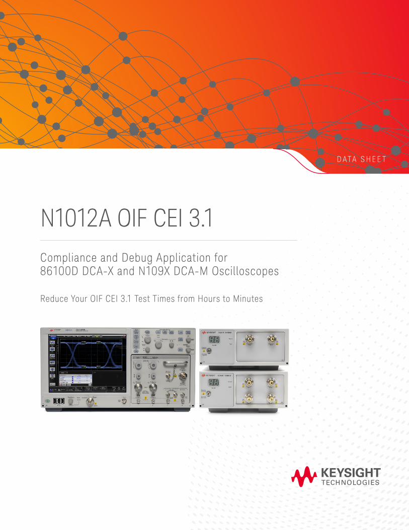
D A T A S H E E T
N1012A OIF CEI 3.1Compliance and Debug Application for 86100D DCA-X and N109X DCA-M Oscilloscopes
Reduce Your OIF CEI 3.1 Test Times from Hours to Minutes
Page 2Find us at www.keysight.com
Introduction
Rapidly increasing worldwide demand for video and data transfer is placing new requirements for network expansion. Designers are creating innovative network elements that allow up to 100 Gb/s, which will be delivered using four lanes of 25 to 28 Gb/s. Extra challenges abound when transferring these signals on printed circuit boards, even for short distances. The Implementation Agreement for Optical Internetworking Forum Common Electrical Interface (OIF CEI) specifies the tests and limits for these devices.
These parameters can take a full day when characterized manually, and the recalculation of factors and CTLE values adds to the time the designer spends on testing. Keysight Technologies, Inc. has created the N1012A OIF CEI 3.1 Compliance and Debug Application for you to simplify measurement of these transmitter parameters and to obtain full results to test limits in a few minutes. This will keep you focused on getting your products to market knowing that your results are built on the heritage and consistency of Keysight measurement technology.
Easy-to-use compliance application that enables you to: – Quickly set up equipment and make transmitter measurements – Test your device to compliance or chosen limits – Debug your device using custom configurations – Remove effects of cables and fixtures – Automatically determine optimal value of CTLE Peaking – Generate reports to share with others
Page 3Find us at www.keysight.com
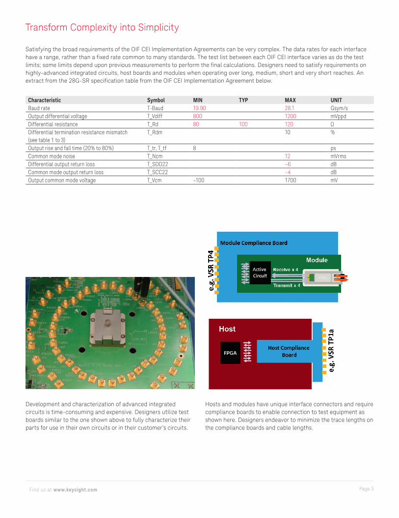
Satisfying the broad requirements of the OIF CEI Implementation Agreements can be very complex. The data rates for each interface have a range, rather than a fixed rate common to many standards. The test list between each OIF CEI interface varies as do the test limits; some limits depend upon previous measurements to perform the final calculations. Designers need to satisfy requirements on highly-advanced integrated circuits, host boards and modules when operating over long, medium, short and very short reaches. An extract from the 28G-SR specification table from the OIF CEI Implementation Agreement below.
Transform Complexity into Simplicity
Hosts and modules have unique interface connectors and require compliance boards to enable connection to test equipment as shown here. Designers endeavor to minimize the trace lengths on the compliance boards and cable lengths.
Development and characterization of advanced integrated circuits is time-consuming and expensive. Designers utilize test boards similar to the one shown above to fully characterize their parts for use in their own circuits or in their customer’s circuits.
Characteristic Symbol MIN TYP MAX UNITBaud rate T-Baud 19.90 28.1 Gsym/sOutput differential voltage T_Vdiff 800 1200 mVppdDifferential resistance T_Rd 80 100 120 ΩDifferential termination resistance mismatch (see table 1 to 3)
T_Rdm 10 %
Output rise and fall time (20% to 80%) T_tr, T_tf 8 psCommon mode noise T_Ncm 12 mVrmsDifferential output return loss T_SDD22 –6 dBCommon mode output return loss T_SCC22 –4 dBOutput common mode voltage T_Vcm –100 1700 mV
Page 4Find us at www.keysight.com
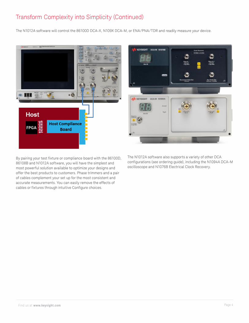
The N1012A software also supports a variety of other DCA configurations (see ordering guide), including the N1094A DCA-M oscilloscope and N1076B Electrical Clock Recovery.
By pairing your test fixture or compliance board with the 86100D, 86108B and N1012A software, you will have the simplest and most powerful solution available to optimize your designs and offer the best products to customers. Phase trimmers and a pair of cables complement your set up for the most consistent and accurate measurements. You can easily remove the effects of cables or fixtures through intuitive Configure choices.
Transform Complexity into Simplicity (Continued)
The N1012A software will control the 86100D DCA-X, N109X DCA-M, or ENA/PNA/TDR and readily measure your device.
Page 5Find us at www.keysight.com
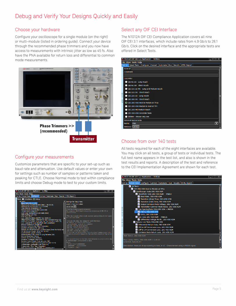
Choose your hardwareConfigure your oscilloscope for a single module (on the right) or multi-module (listed in ordering guide). Connect your device through the recommended phase trimmers and you now have access to measurements with intrinsic jitter as low as 45 fs. Also have the PNA available for return loss and differential to common mode measurements.
Debug and Verify Your Designs Quickly and Easily
Select any OIF CEI InterfaceThe N1012A OIF CEI Compliance Application covers all nine OIF CEI 3.1 interfaces, which include rates from 4.9 Gb/s to 28.1 Gb/s. Click on the desired interface and the appropriate tests are offered in Select Tests.
Configure your measurementsCustomize parameters that are specific to your set-up such as baud rate and attenuation. Use default values or enter your own for settings such as number of samples or patterns taken and peaking for CTLE. Choose Normal mode to test within compliance limits and choose Debug mode to test to your custom limits.
Choose from over 140 testsAll tests required for each of the eight interfaces are available. You may click on all tests, a group of tests or individual tests. The full test name appears in the test list, and also is shown in the test results and reports. A description of the test and reference to the CEI Implementation Agreement are shown for each test.
Page 6Find us at www.keysight.com
Debug and Verify Your Designs Quickly and Easily (Continued)
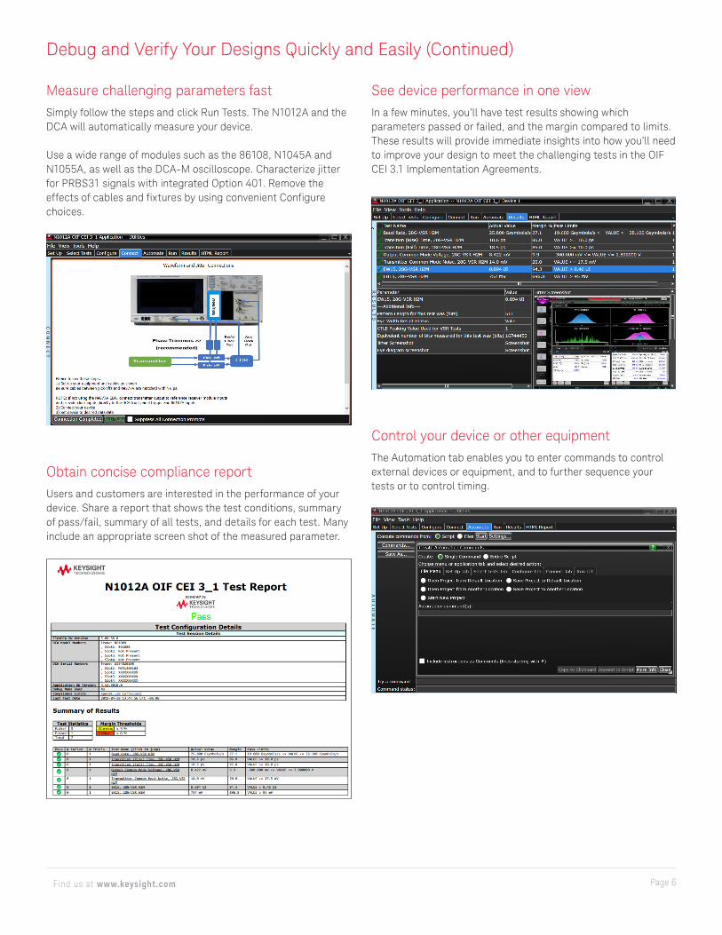
Measure challenging parameters fastSimply follow the steps and click Run Tests. The N1012A and the DCA will automatically measure your device.
Use a wide range of modules such as the 86108, N1045A and N1055A, as well as the DCA-M oscilloscope. Characterize jitter for PRBS31 signals with integrated Option 401. Remove the effects of cables and fixtures by using convenient Configure choices.
Obtain concise compliance reportUsers and customers are interested in the performance of your device. Share a report that shows the test conditions, summary of pass/fail, summary of all tests, and details for each test. Many include an appropriate screen shot of the measured parameter.
See device performance in one viewIn a few minutes, you’ll have test results showing which parameters passed or failed, and the margin compared to limits. These results will provide immediate insights into how you’ll need to improve your design to meet the challenging tests in the OIF CEI 3.1 Implementation Agreements.
Control your device or other equipmentThe Automation tab enables you to enter commands to control external devices or equipment, and to further sequence your tests or to control timing.
Page 7Find us at www.keysight.com
More Features to Further Streamline Your Development
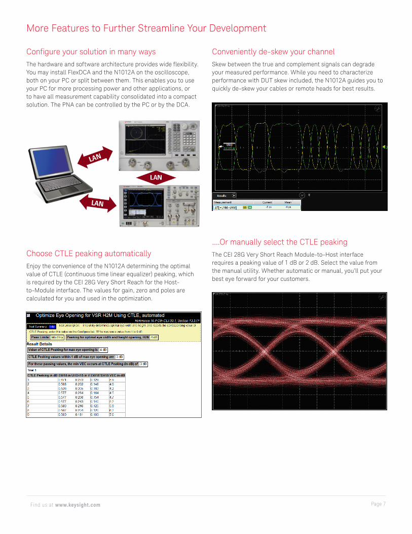
Choose CTLE peaking automaticallyEnjoy the convenience of the N1012A determining the optimal value of CTLE (continuous time linear equalizer) peaking, which is required by the CEI 28G Very Short Reach for the Host-to-Module interface. The values for gain, zero and poles are calculated for you and used in the optimization.
Configure your solution in many waysThe hardware and software architecture provides wide flexibility. You may install FlexDCA and the N1012A on the oscilloscope, both on your PC or split between them. This enables you to use your PC for more processing power and other applications, or to have all measurement capability consolidated into a compact solution. The PNA can be controlled by the PC or by the DCA.
Conveniently de-skew your channelSkew between the true and complement signals can degrade your measured performance. While you need to characterize performance with DUT skew included, the N1012A guides you to quickly de-skew your cables or remote heads for best results.
....Or manually select the CTLE peakingThe CEI 28G Very Short Reach Module-to-Host interface requires a peaking value of 1 dB or 2 dB. Select the value from the manual utility. Whether automatic or manual, you’ll put your best eye forward for your customers.
Page 8Find us at www.keysight.com
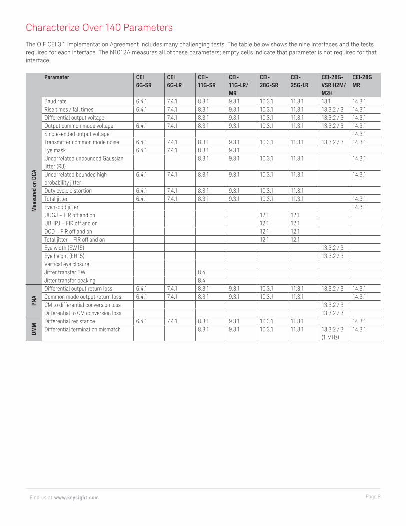
Characterize Over 140 Parameters
The OIF CEI 3.1 Implementation Agreement includes many challenging tests. The table below shows the nine interfaces and the tests required for each interface. The N1012A measures all of these parameters; empty cells indicate that parameter is not required for that interface.
Parameter CEI 6G-SR
CEI 6G-LR
CEI- 11G-SR
CEI-11G-LR/MR
CEI- 28G-SR
CEI- 25G-LR
CEI-28G-VSR H2M/M2H
CEI-28G MR
Mea
sure
d on
DCA
Baud rate 6.4.1 7.4.1 8.3.1 9.3.1 10.3.1 11.3.1 13.1 14.3.1Rise times / fall times 6.4.1 7.4.1 8.3.1 9.3.1 10.3.1 11.3.1 13.3.2 / 3 14.3.1Differential output voltage 7.4.1 8.3.1 9.3.1 10.3.1 11.3.1 13.3.2 / 3 14.3.1Output common mode voltage 6.4.1 7.4.1 8.3.1 9.3.1 10.3.1 11.3.1 13.3.2 / 3 14.3.1Single-ended output voltage 14.3.1Transmitter common mode noise 6.4.1 7.4.1 8.3.1 9.3.1 10.3.1 11.3.1 13.3.2 / 3 14.3.1Eye mask 6.4.1 7.4.1 8.3.1 9.3.1Uncorrelated unbounded Gaussian jitter (RJ)
8.3.1 9.3.1 10.3.1 11.3.1 14.3.1
Uncorrelated bounded high probability jitter
6.4.1 7.4.1 8.3.1 9.3.1 10.3.1 11.3.1 14.3.1
Duty cycle distortion 6.4.1 7.4.1 8.3.1 9.3.1 10.3.1 11.3.1Total jitter 6.4.1 7.4.1 8.3.1 9.3.1 10.3.1 11.3.1 14.3.1Even-odd jitter 14.3.1UUGJ – FIR off and on 12.1 12.1UBHPJ – FIR off and on 12.1 12.1DCD – FIR off and on 12.1 12.1Total jitter – FIR off and on 12.1 12.1Eye width (EW15) 13.3.2 / 3Eye height (EH15) 13.3.2 / 3Vertical eye closureJitter transfer BW 8.4Jitter transfer peaking 8.4
PNA
Differential output return loss 6.4.1 7.4.1 8.3.1 9.3.1 10.3.1 11.3.1 13.3.2 / 3 14.3.1Common mode output return loss 6.4.1 7.4.1 8.3.1 9.3.1 10.3.1 11.3.1 14.3.1CM to differential conversion loss 13.3.2 / 3Differential to CM conversion loss 13.3.2 / 3
DMM
Differential resistance 6.4.1 7.4.1 8.3.1 9.3.1 10.3.1 11.3.1 14.3.1Differential termination mismatch 8.3.1 9.3.1 10.3.1 11.3.1 13.3.2 / 3
(1 MHz)14.3.1
Page 9Find us at www.keysight.com
Choose Industry-Leading Solutions
Keysight offers a wide range of electrical and optical test solutions to address current and emerging communications standards. For OIF-CEI-3.1, you may choose a hardware combination that addresses your test needs for today, and into the future:
1. 86100D DCA-X with 86108B (Integrated “One-Box” solution) - recommended2. 86100D DCA-X with DCA module and external clock recovery3. N109X Electrical DCA-M with external clock recovery
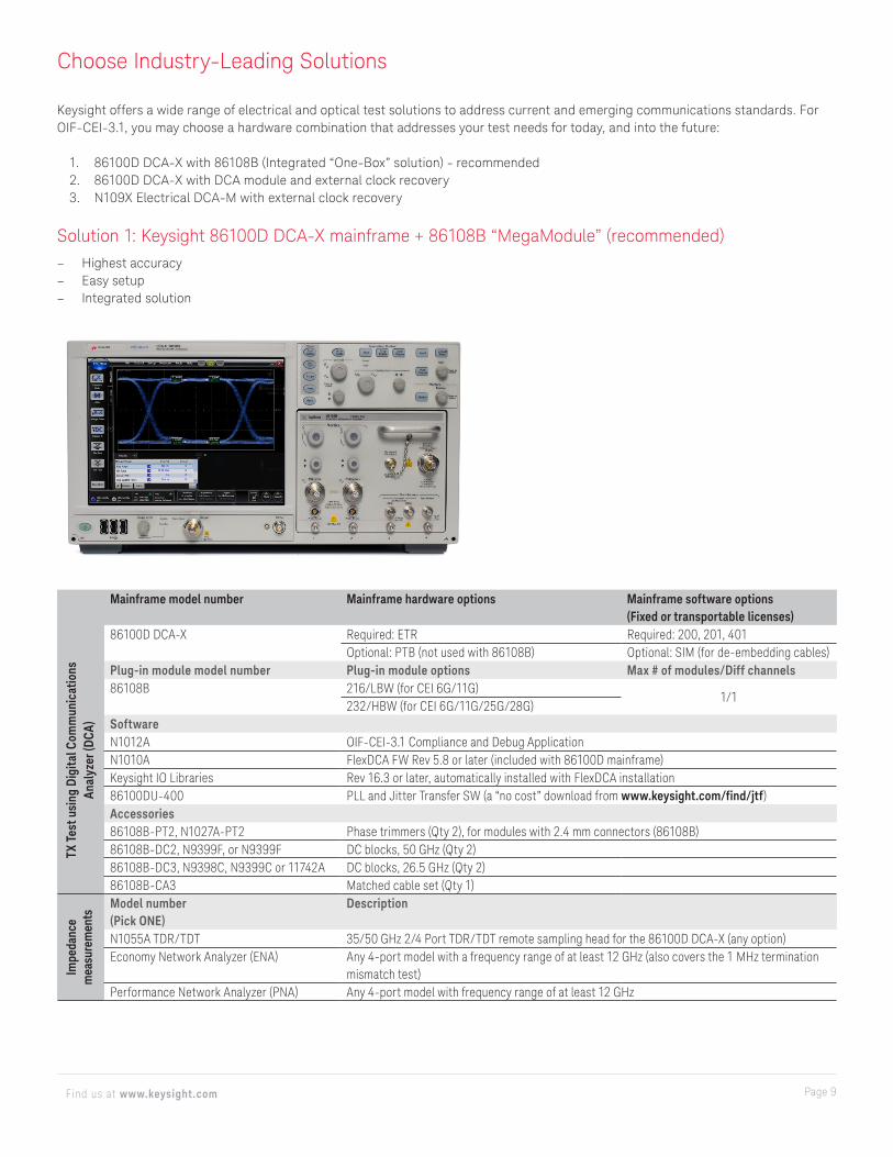
Solution 1: Keysight 86100D DCA-X mainframe + 86108B “MegaModule” (recommended) – Highest accuracy – Easy setup – Integrated solution
Mainframe model number Mainframe hardware options Mainframe software options (Fixed or transportable licenses)
86100D DCA-X Required: ETR Required: 200, 201, 401Optional: PTB (not used with 86108B) Optional: SIM (for de-embedding cables)
Plug-in module model number Plug-in module options Max # of modules/Diff channels86108B 216/LBW (for CEI 6G/11G)
1/1232/HBW (for CEI 6G/11G/25G/28G)
SoftwareN1012A OIF-CEI-3.1 Compliance and Debug ApplicationN1010A FlexDCA FW Rev 5.8 or later (included with 86100D mainframe)Keysight IO Libraries Rev 16.3 or later, automatically installed with FlexDCA installation86100DU-400 PLL and Jitter Transfer SW (a “no cost” download from www.keysight.com/find/jtf)Accessories86108B-PT2, N1027A-PT2 Phase trimmers (Qty 2), for modules with 2.4 mm connectors (86108B)86108B-DC2, N9399F, or N9399F DC blocks, 50 GHz (Qty 2)86108B-DC3, N9398C, N9399C or 11742A DC blocks, 26.5 GHz (Qty 2)86108B-CA3 Matched cable set (Qty 1)Model number (Pick ONE)
Description
N1055A TDR/TDT 35/50 GHz 2/4 Port TDR/TDT remote sampling head for the 86100D DCA-X (any option)Economy Network Analyzer (ENA) Any 4-port model with a frequency range of at least 12 GHz (also covers the 1 MHz termination
mismatch test)Performance Network Analyzer (PNA) Any 4-port model with frequency range of at least 12 GHz
TX T
est u
sing
Dig
ital C
omm
unic
atio
ns
Anal
yzer
(DCA
)Im
peda
nce
mea
sure
men
ts
Page 10Find us at www.keysight.com
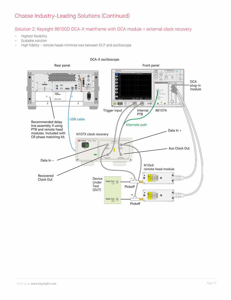
Choose Industry-Leading Solutions (Continued)
Solution 2: Keysight 86100D DCA-X mainframe with DCA module + external clock recovery – Highest flexibility – Scalable solution – High fidelity – remote heads minimize loss between DUT and oscilloscope
Data Out(–)
Data Out(+)
Locked
Slot ID
DCA-M N1076A
Data In -2.92 mm, 5 0Ω
2 Vpp Max
Data In +2.92 mm, 5 0Ω
2 Vpp Max
Recovered Clock Out2.92 mm, 5 0Ω
Aux Clock Out2.92 mm, 5 0Ω, 4-8 GHz
Clock Recovery
Markers
TriggerTrigger Level DC Cal
50Ω2Vpp Max
Horizontal
Vertical
Press toselect
Press toselect
Press toselect
Press toselect Source
User
Position
Mode Acquisition Control
Module Front Panel
Free Run
Armed
Trig’d
DefaultSetup
ClearDisplay
StopSingleRunAuto
Scale
Apps
Multi-Purpose
TDR/TDT
Jitter
Scope
Marker
LocalEye/Mask
40 Gb/s
20 Gb/s
10 Gb/s
Caution: Connect ReferenceClock to only one input at a time
2.4 mm50
3.5 mm50
2V Max DC
86107A
Ch A
Ch B
N1045A
±2
V M
ax5
lb-in Max Torque
Static
Sensitive
N1045A
60G
Hz R
emote
Sam
pling Head
1.85m
m 5
0Ω(2.4
mm
compatible)
Ch B
±2
V M
ax5
lb-in Max Torque
Static
Sensitive
N1045A
6 0G
Hz R
emote
Sam
pling Head
1.85m
m 5
0Ω(2.4
mm
compatible)
Ch A
ICES/NMB-001ISM GRP.1 CLASS A
C US
WARNING: NO OPERATORSERVICEABLE PARTS INSIDE,REFER SERVICING TO QUALIFIEDPERSONNEL
TRIGGERGATE (TTL)
PRECISIONTIME BASE
DELAY LOOP
INPUT
OUTPUT
+
–Recovered Clock Out
Recommended delay line assembly if using PTB and remote head modules. Included with CR phase matching kit.
Data In –
Front panel
DCA plug-in module
86107ATrigger input Internal PTB
Alternate path
N107X clock recovery
USB cable
Data In +
DCA-X oscilloscope
Rear panel
N104X remote head module
Aux Clock Out
Device Under Test (DUT)
Pickoff
Pickoff
Page 11Find us at www.keysight.com
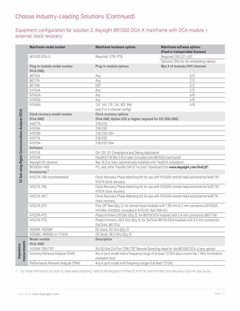
Mainframe model number Mainframe hardware options Mainframe software options (Fixed or transportable licenses)
86100D DCA-X Required: ETR, PTB Required: 200 201, 401Optional: SIM (for de-embedding cables)
Plug-in module model number (Pick ONE)
Plug-in module options Max # of modules/Diff channels
86112A Any 2/286117A Any 2/286118A H01 2/254754A Any 2/2N1045A Any 4/8N1055A Any 4/8N1046A 12F, 14F, 72F, 74F, 82F, 84F
(any 2 or 4 channel config)4/8
Clock recovery model number (Pick ONE)
Clock recovery options (Pick ONE; Option 232 or higher required for CEI 25G/28G)
N4877A 216/232N1076A 216/232N1076B 216/232/264N1077A 216/232N1078A 216/232/264SoftwareN1012A OIF-CEI-3.1 Compliance and Debug ApplicationN1010A FlexDCA FW Rev 5.8 or later (included with 86100D mainframe)Keysight IO Libraries Rev 16.3 or later, automatically installed with FlexDCA installation86100DU-400 PLL and Jitter Transfer SW (a “no cost” download from www.keysight.com/find/jtf)Accessories 1
N1027A-76B (recommended) Clock Recovery Phase Matching Kit for use with N104XA remote head and external N4877A/N107X clock recovery
N1027A-76A Clock Recovery Phase Matching Kit for use with N104XA remote head and external N4877A/N107X clock recovery
N1027A-MC1 Clock Recovery Phase Matching Kit for use with N104XA remote head and external N4877A clock recovery
N1027A-2P2 Pick-Off Tees (Qty 2), for remote head modules with 1.85 mm/2.4 mm connectors (N1045A, N1046A, N1055A), (included in N1027A-76A/76B Kit)
N1027A-PT2 Phase trimmers,50 GHz (Qty 2), for 861XX DCA modules with 2.4 mm connectors (86117A)N1027A-PT3 Phase trimmers, 26.5 GHz (Qty 2), for 54754A/861XX DCA modules with 3.5 mm connectors
(54754A, 86112A)N9399F, N9399F DC block, 50 GHz (Qty 2)N9398C, N9399C or 11742A DC block, 26.5 GHz (Qty 2)Model number (Pick ONE)
Description
N1055A TDR/TDT 35/50 GHz 2/4 Port TDR/TDT Remote Sampling Head for the 86100D DCA-X (any option)Economy Network Analyzer (ENA) Any 4-port model with a frequency range of at least 12 GHz (also covers the 1 MHz termination
mismatch test)Performance Network Analyzer (PNA) Any 4-port model with frequency range of at least 12 GHz
1. For more information on clock-to-data delay matching, refer to the Keysight N1076A/B, N1077A, and N1078A Clock Recovery DCA-M User Guide.
TX T
est u
sing
Dig
ital C
omm
unic
atio
ns A
naly
zer (
DCA)
Impe
danc
e m
easu
rem
ents
Choose Industry-Leading Solutions (Continued)
Equipment configuration for solution 2: Keysight 86100D DCA-X mainframe with DCA module + external clock recovery
Page 12Find us at www.keysight.com
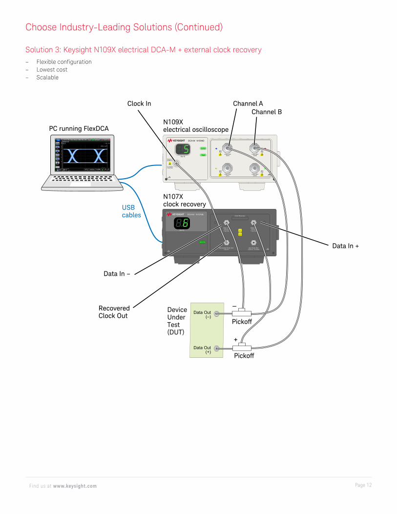
Choose Industry-Leading Solutions (Continued)
Solution 3: Keysight N109X electrical DCA-M + external clock recovery – Flexible configuration – Lowest cost – Scalable
Data Out(–)
Data Out(+)
Data In -2.92 mm
1 Vpp Max
Data In +2.92 mm
1 Vpp Max
Recovered Clock Out2.92 mm
Aux Clock Out2.92 mm, 8-16 GHz
Clock Recovery
Locked
Slot ID
DCA-M N1076B
Clock In(2.92mm)
Armed
Slot IDTrig’d
DCA-M N1094D
0.1-32 GHz2 Vpp Max
Ch C Ch D2.4mm 50Ω 2.4mm 50Ω
Ch A Ch B2.4mm 50Ω 2.4mm 50Ω
±2 VMax
±2 VMax
±2 VMax
±2 VMax
+
–
Data In +
N109X electrical oscilloscope
Clock In Channel AChannel B
USB cables
N107X clock recovery
PC running FlexDCA
Recovered Clock Out
Data In –
Device Under Test (DUT)
Pickoff
Pickoff
This information is subject to change without notice. © Keysight Technologies, 2012 - 2018, Published in USA, June 12, 2018, 5991-0561EN
Page 13Find us at www.keysight.com
Learn more at: www.keysight.comFor more information on Keysight Technologies’ products, applications or services,
please contact your local Keysight office. The complete list is available at:
www.keysight.com/find/contactus
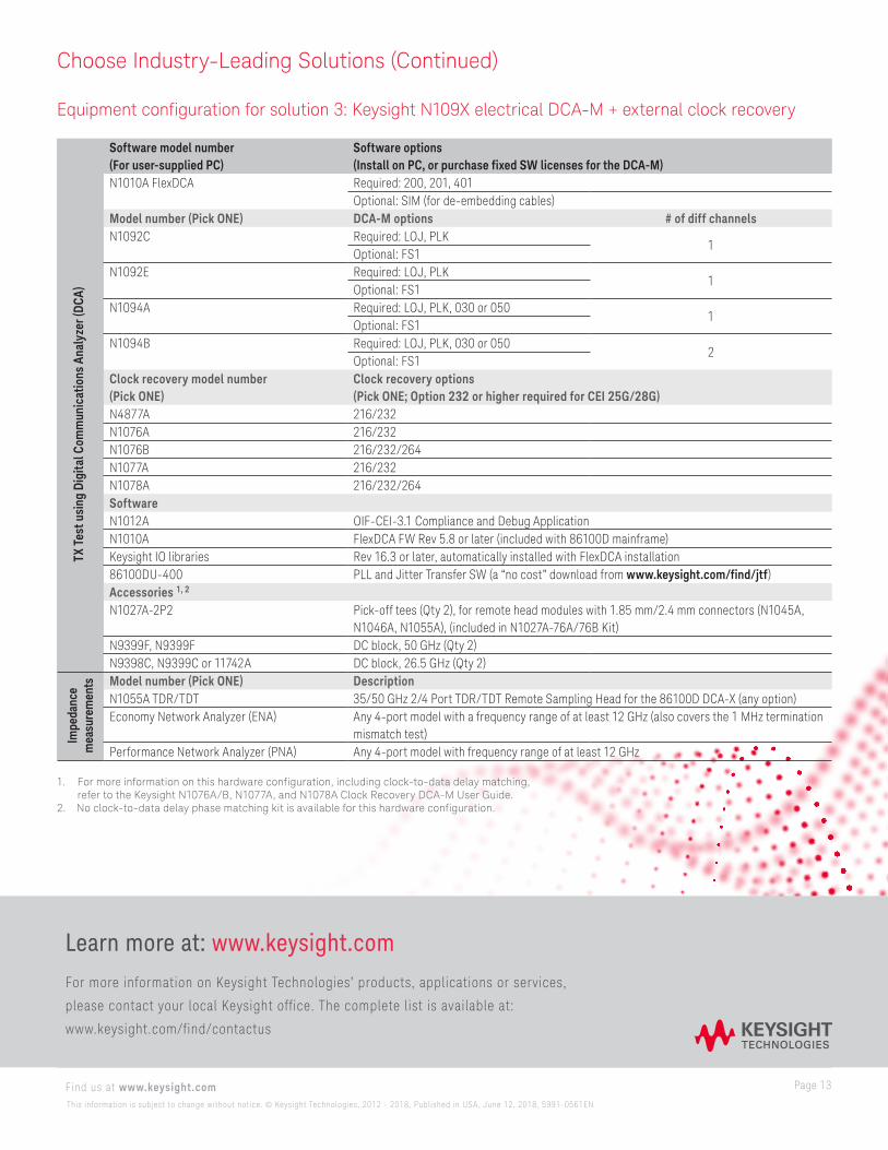
Software model number (For user-supplied PC)
Software options (Install on PC, or purchase fixed SW licenses for the DCA-M)
N1010A FlexDCA Required: 200, 201, 401Optional: SIM (for de-embedding cables)
Model number (Pick ONE) DCA-M options # of diff channelsN1092C Required: LOJ, PLK
1Optional: FS1
N1092E Required: LOJ, PLK1
Optional: FS1N1094A Required: LOJ, PLK, 030 or 050
1Optional: FS1
N1094B Required: LOJ, PLK, 030 or 0502
Optional: FS1Clock recovery model number (Pick ONE)
Clock recovery options (Pick ONE; Option 232 or higher required for CEI 25G/28G)
N4877A 216/232N1076A 216/232N1076B 216/232/264N1077A 216/232N1078A 216/232/264SoftwareN1012A OIF-CEI-3.1 Compliance and Debug ApplicationN1010A FlexDCA FW Rev 5.8 or later (included with 86100D mainframe)Keysight IO libraries Rev 16.3 or later, automatically installed with FlexDCA installation86100DU-400 PLL and Jitter Transfer SW (a “no cost” download from www.keysight.com/find/jtf)Accessories 1, 2
N1027A-2P2 Pick-off tees (Qty 2), for remote head modules with 1.85 mm/2.4 mm connectors (N1045A, N1046A, N1055A), (included in N1027A-76A/76B Kit)
N9399F, N9399F DC block, 50 GHz (Qty 2)N9398C, N9399C or 11742A DC block, 26.5 GHz (Qty 2)Model number (Pick ONE) DescriptionN1055A TDR/TDT 35/50 GHz 2/4 Port TDR/TDT Remote Sampling Head for the 86100D DCA-X (any option)Economy Network Analyzer (ENA) Any 4-port model with a frequency range of at least 12 GHz (also covers the 1 MHz termination
mismatch test)Performance Network Analyzer (PNA) Any 4-port model with frequency range of at least 12 GHz
1. For more information on this hardware configuration, including clock-to-data delay matching, refer to the Keysight N1076A/B, N1077A, and N1078A Clock Recovery DCA-M User Guide.
2. No clock-to-data delay phase matching kit is available for this hardware configuration.
TX T
est u
sing
Dig
ital C
omm
unic
atio
ns A
naly
zer (
DCA)
Impe
danc
e m
easu
rem
ents
Choose Industry-Leading Solutions (Continued)
Equipment configuration for solution 3: Keysight N109X electrical DCA-M + external clock recovery