Embed Size (px)
Citation preview

7/27/2019 N110IL4
http://slidepdf.com/reader/full/n110il4 1/28
1EGR 110 – Inventor Lecture #4
Features in Inventor
Inventor includes two types of
geometric features:
• Sketched features (includingextrusions, revolutions, and
sweeps)
• Placed features (including holes,
fillets, chamfers, and shells)
Sketched features required that 1 or
2 sketches be drawn first. Placed
features do not require a sketch.
So far we have only used sketchedfeatures (extrusions) to create solid
models.
The Model browser shows a series
of sequential sketched and placed
features (see example to the right).
Sketched featur e
Sketched featur e
Sketched featur e
Sketched featur e
Placed feature
Placed featur e
Placed featur e
Placed feature
Placed featur e

7/27/2019 N110IL4
http://slidepdf.com/reader/full/n110il4 2/28
2EGR 110 – Inventor Lecture #4
Holes
We can create holes using extrusions, but an easier way is to use Hole from the 3D
Model menu.
Example:
Create a simple solid block (extrude a rectangle) and switch to an isometric view.
Select Hole from the 3D Model menu (or press H on the keyboard).

7/27/2019 N110IL4
http://slidepdf.com/reader/full/n110il4 3/28
3EGR 110 – Inventor Lecture #4
Holes (continued)
On the Hole menu, select Linear under Placement . Then select three items:
1) Face – Pick the face where you want the hole (pick the approximate location)
2) Reference 1 –
Pick an edge for a distance measurement to the center of the hole3) Reference 2 – Pick another edge for a second distance measurement

7/27/2019 N110IL4
http://slidepdf.com/reader/full/n110il4 4/28
4EGR 110 – Inventor Lecture #4
Holes (continued)
Experiment by creating various types of holes, including:
• Through holes
• Holes with a specified depth
• Tapped (threaded) holes
• Countersink holes
• Counterbore holes
• Holes that intersect holes
Also try editing various holes to
change their type, size, location, etc.

7/27/2019 N110IL4
http://slidepdf.com/reader/full/n110il4 5/28
5EGR 110 – Inventor Lecture #4
Threads
Note that threads placed inside holes are bit-map images added for appearance only (although the
thread sizes used can be referred to when dimensioning). Threads do not appear on isometrics in
drawing files; however, the threads are properly represented in other views.
Dashed li nes
represents threads

7/27/2019 N110IL4
http://slidepdf.com/reader/full/n110il4 6/28
6
EGR 110 – Inventor Lecture #4
External threads – Internal threads are typically added with
the Hole command. External threads can be applied to the
3D model using the Thread command.
Example: Try creating the following object. Discuss
the sequence of operations used as shown in the browser.
7/27/2019 N110IL4
http://slidepdf.com/reader/full/n110il4 7/28
7EGR 110 – Inventor Lecture #4
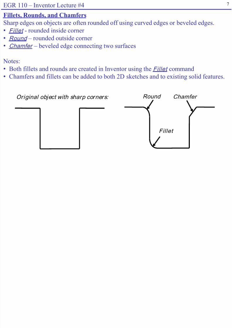
Fillets, Rounds, and Chamfers
Sharp edges on objects are often rounded off using curved edges or beveled edges.
• Fillet - rounded inside corner
•
Round –
rounded outside corner• Chamfer – beveled edge connecting two surfaces
Notes:
• Both fillets and rounds are created in Inventor using the Fillet command
• Chamfers and fillets can be added to both 2D sketches and to existing solid features.
ChamferRound
Fillet
Original object with sharp corners:

7/27/2019 N110IL4
http://slidepdf.com/reader/full/n110il4 8/28
8EGR 110 – Inventor Lecture #4
Adding a Fillet to a 2D Sketch
Pick two edges
and fi ll et (round)wil l appear
Enter radius

7/27/2019 N110IL4
http://slidepdf.com/reader/full/n110il4 9/28
7/27/2019 N110IL4
http://slidepdf.com/reader/full/n110il4 10/28
10EGR 110 – Inventor Lecture #4
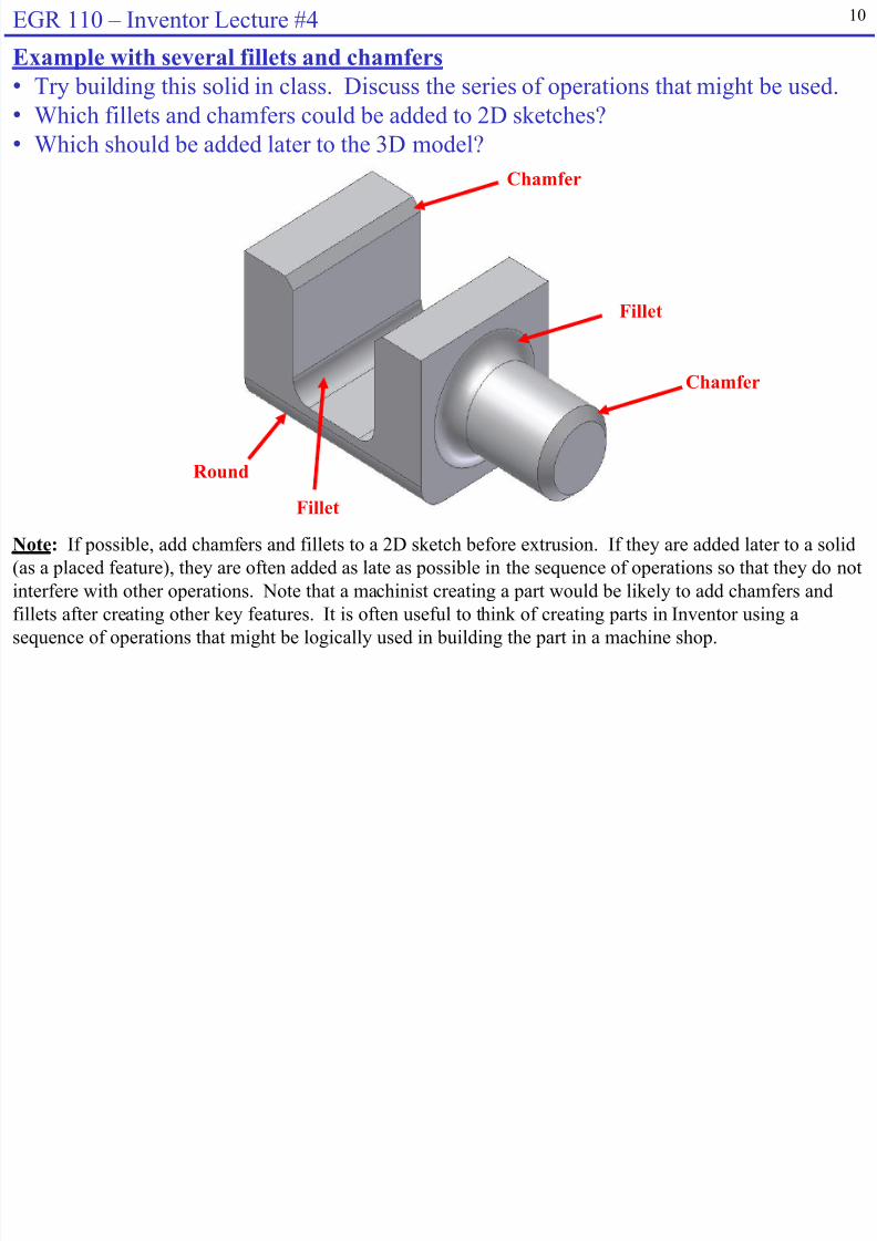
Example with several fillets and chamfers
• Try building this solid in class. Discuss the series of operations that might be used.
• Which fillets and chamfers could be added to 2D sketches?
•
Which should be added later to the 3D model?
Fillet
Chamfer
Round
Chamfer
Fillet
Note: If possible, add chamfers and fillets to a 2D sketch before extrusion. If they are added later to a solid
(as a placed feature), they are often added as late as possible in the sequence of operations so that they do not
interfere with other operations. Note that a machinist creating a part would be likely to add chamfers and
fillets after creating other key features. It is often useful to think of creating parts in Inventor using asequence of operations that might be logically used in building the part in a machine shop.

7/27/2019 N110IL4
http://slidepdf.com/reader/full/n110il4 11/28

7/27/2019 N110IL4
http://slidepdf.com/reader/full/n110il4 12/2812
EGR 110 – Inventor Lecture #4
Quick Test
The profile shown could be revolved around lines A, B, C, D, E, or F.
Can you determine which line was used for each solid shown below?
Circle the correct letter in each case.
A
B
D
C
E
F
A B C D E F A B C D E F A B C D E F
A B C D E F A B C D E F A B C D E F
7/27/2019 N110IL4
http://slidepdf.com/reader/full/n110il4 13/28

7/27/2019 N110IL4
http://slidepdf.com/reader/full/n110il4 14/28
14EGR 110 – Inventor Lecture #4
Symmetrical Features
Symmetrical Features can be added in Inventor using:
• Circular Pattern
•
Rectangular Pattern• M ir ror Pattern
The patterns above can be added to the following:
• 2D Sketch
• 3D Model

7/27/2019 N110IL4
http://slidepdf.com/reader/full/n110il4 15/28

7/27/2019 N110IL4
http://slidepdf.com/reader/full/n110il4 16/28
17G 110 #4

7/27/2019 N110IL4
http://slidepdf.com/reader/full/n110il4 17/28
17EGR 110 – Inventor Lecture #4
Example of Mirror Pattern
Mirror
Line
1. Draw half of object. I nclude mir rorl ine (construction l ine may be useful )
2. Select sketch features tomirr or and the mirr or l ine
3. Extrude to create
soli d model
18EGR 110 I L #4
7/27/2019 N110IL4
http://slidepdf.com/reader/full/n110il4 18/28
18EGR 110 – Inventor Lecture #4
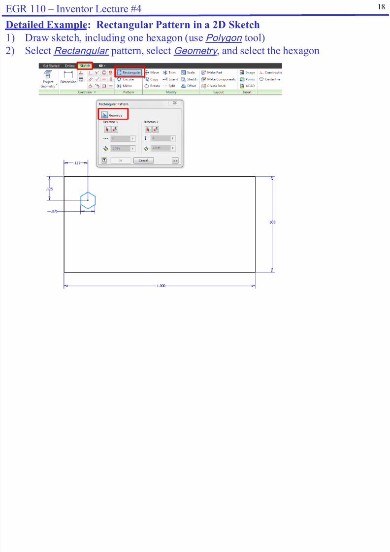
Detailed Example: Rectangular Pattern in a 2D Sketch
1) Draw sketch, including one hexagon (use Polygon tool)
2) Select Rectangular pattern, select Geometry , and select the hexagon
19EGR 110 I L #4

7/27/2019 N110IL4
http://slidepdf.com/reader/full/n110il4 19/28
19EGR 110 – Inventor Lecture #4
Detailed Example: Rectangular Pattern in a 2D Sketch (continued)
3) Select Di rection 1 and pick a line in the direction the pattern should go (a
horizontal line in this case). An arrow appears showing the direction selected. If
the arrow is in the opposite direction, select the Fl ip button.
4) Enter the number of pattern elements and spacing for Direction 1
Number of elements
Spacing between elements
Di rection arrow and F li p
button
Ar row appears in the
direction selected
for Di rection 1

7/27/2019 N110IL4
http://slidepdf.com/reader/full/n110il4 20/28
21EGR 110 I t L t #4

7/27/2019 N110IL4
http://slidepdf.com/reader/full/n110il4 21/28
21EGR 110 – Inventor Lecture #4
Detailed Example: Circular Pattern in a 3D Model
Create a wheel with 6 equally space threaded holes shown below.
1. Create the basic wheel using a revolution
7/27/2019 N110IL4
http://slidepdf.com/reader/full/n110il4 22/28
23EGR 110 I t L t #4

7/27/2019 N110IL4
http://slidepdf.com/reader/full/n110il4 23/28
23EGR 110 – Inventor Lecture #4
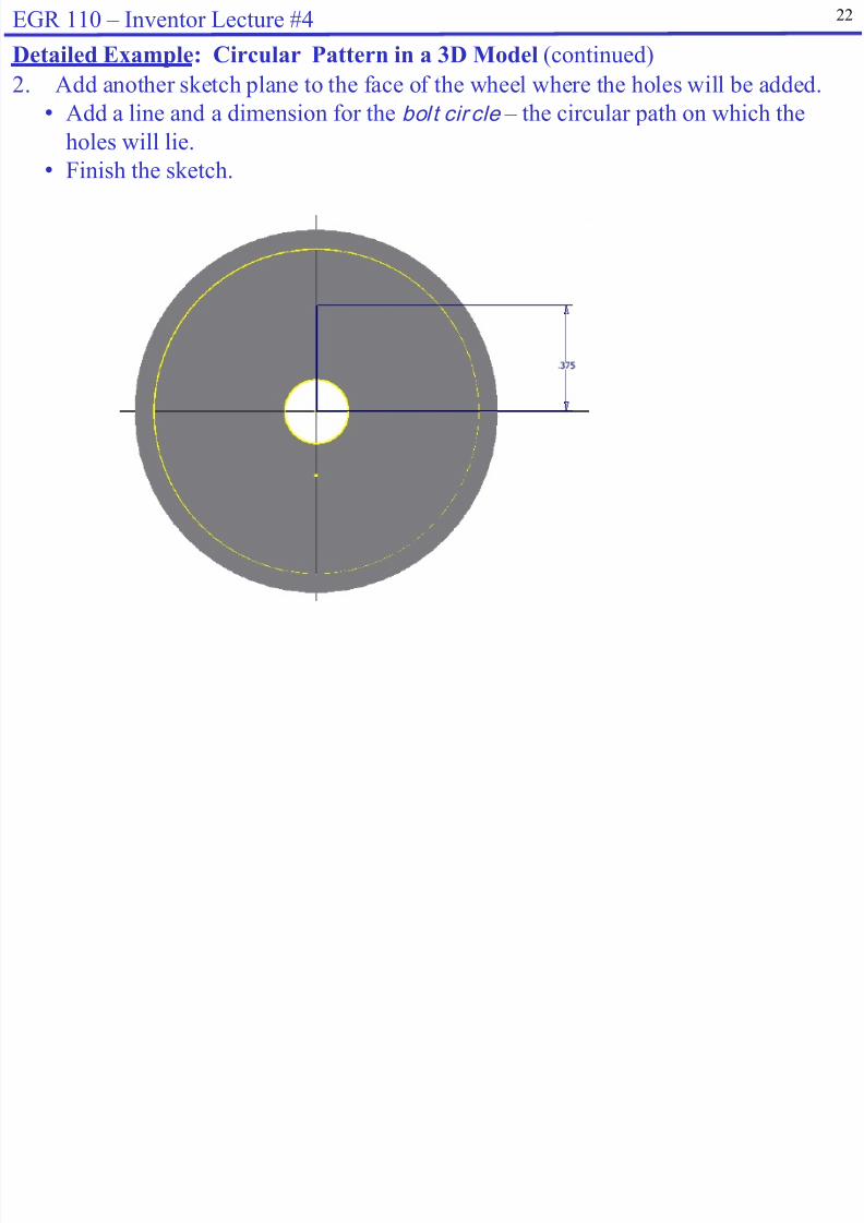
Detailed Example: Circular Pattern in a 3D Model (continued)
3. Select Hole from the 3D Model menu. Use the following options:
• Placement: From Sketch
• Pick the center point where the hole is to be placed
• Termination: Through All
• Diameter: 0.75 in (or your choice)
• Select Threaded Hole and then select OK

7/27/2019 N110IL4
http://slidepdf.com/reader/full/n110il4 24/28
25EGR 110 Inventor Lecture #4

7/27/2019 N110IL4
http://slidepdf.com/reader/full/n110il4 25/28
25EGR 110 – Inventor Lecture #4
f15
f25
f5
Front Right
f15
f25
f5
Front
Centerlines and Linear Diametric Dimensions
For revolved features it is common to use l inear diametr ic dimensions instead of
radial dimensions . An example of the difference is shown below.
Example using
radial dimensions
Example using
l inear diametr ic dimensions

7/27/2019 N110IL4
http://slidepdf.com/reader/full/n110il4 26/28
27EGR 110 Inventor Lecture #4

7/27/2019 N110IL4
http://slidepdf.com/reader/full/n110il4 27/28
27EGR 110 – Inventor Lecture #4
Revolved Features with Linear Diametric Dimensions (continued)
2. Add dimensions by selecting:
a) The centerline (not its endpoint)
b) A line on the profile3. Finish the sketch and revolve the sketch
28EGR 110 Inventor Lecture #4
7/27/2019 N110IL4
http://slidepdf.com/reader/full/n110il4 28/28
28EGR 110 – Inventor Lecture #4
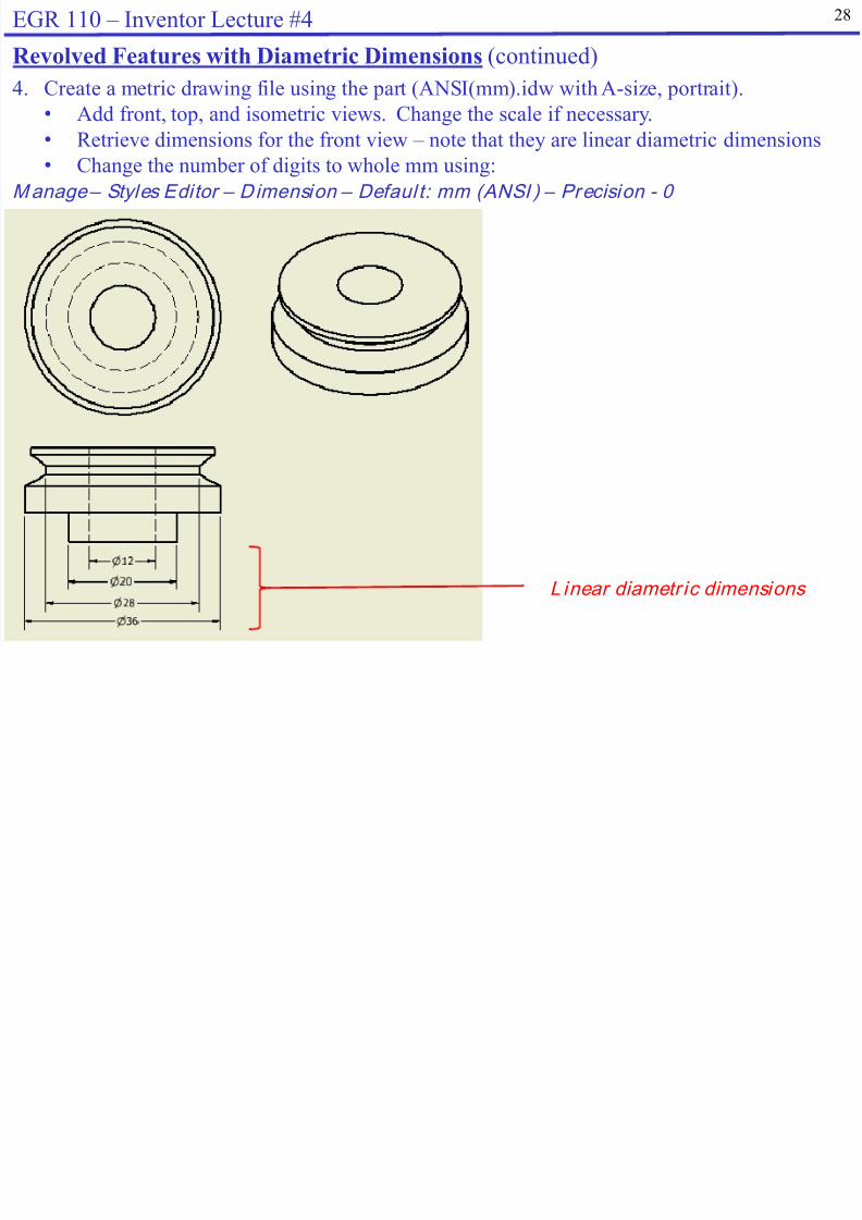
Revolved Features with Diametric Dimensions (continued)
4. Create a metric drawing file using the part (ANSI(mm).idw with A-size, portrait).
• Add front, top, and isometric views. Change the scale if necessary.
• Retrieve dimensions for the front view – note that they are linear diametric dimensions
• Change the number of digits to whole mm using:
Manage – Styles Editor – Dimension – Defaul t: mm (ANSI ) – Precision - 0
L inear diametr ic dimensions


