Embed Size (px)
Citation preview
85
WOOD RESEARCH 63 (1): 2018 85-96
NAIL METAL CONNECTOR PLATE – LOAD-BEARING
CAPACITY OF CONNECTOR IN FUNCTION OF
NAIL-TO-PLATE CONNECTION RIGIDITY
Žikica Tekić, Aleksandra Nenadović, Saša ĐorđevićUniversity of Belgrade, Faculty of Architecture
Belgrade, Serbia
Snježan LukićTown Planning and Building Inspector, Municipality Ugljevik
Ugljevik, Republic of Srpska - Bosnia and Herzegovina
(Received June 2017)
ABSTRACT
This paper deals with the results of experimental determination of load-bearing capacity of structural timber connections realized by nail metal connector plates, in the function of nail to steel plate connection rigidity. In the first group of test samples, the nails are embedded in pre-drilled holes in the steel plate. In the second group, the nails are embedded in pre-drilled holes and then the head of nail is welded to steel plate by its circumference. The main originality of the study is reflected in the achievement of rigidity of the connection of nails and the sleet plate, that is, in provision of rotation resistance, which leads to the plastic hinge formation at the surface of the steel plate, and thus to the increase of connection ductility. The study showed to what extent the degree of nail-to-plate connection rigidity affects the load-bearing capacity of structural timber member connections. Experimental testing was conducted in accordance with the provisions of Eurocode 5.
KEYWORDS: failure mode, load-bearing capacity, metal connector plate, nail, nail-to-plate connection rigidity
INTRODUCTION
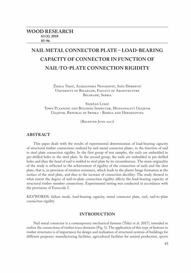
Nail metal connector is a contemporary mechanical fastener (Tekić et al. 2017), intended to realize the connections of timber truss elements (Fig. 1). The application of this type of fastener in timber structures is of importance for design and realisation of structural systems of buildings for different purposes: manufacturing facilities, agricultural facilities for animal production, sports
86
WOOD RESEARCH
facilities, exhibition halls, showrooms, hangars for agricultural machines, multi-purpose halls, etc. This type of metal connector differs from standard metal connectors which are produced by perforation of the steel sheet, where, in the final form, the teeth of connector take a certain position in relation to the longitudinal axis of the connector. The position and geometry of the holes in the standard connector plate, which remain after the extraction of teeth out of connector’s plane, affect its resistance to pressure, tension and shear. Nail metal connector is designed to eliminate the deficiencies of standard types of metal connectors, in order to achieve higher load bearing capacity of connections constituted of timber elements. It is composed of metal plate and nails, which are perpendicular to the metal plate. The nails which are used for the production of connector have a circular cross-section. In this way, the angle α, as the angle between direction of force and direction of the longitudinal axis of connector, which is characteristic for standard types of metal connectors, can be excluded from the connection dimensioning, thus simplifying the dimensioning process.
Fig. 1: Nail metal connector plate.
Dimensioning of connections in timber structures, realized by dowels (nails, bolts, screws), is conducted according to Johansen's theory (Johansen 1949). The nail is modelled as a beam where plastic hinges form under the loading of the embedding pressure from the surrounding timber. For load-bearing capacity of the connection, the lowest value obtained for possible failure modes of the connection is adopted. This theory is the basis for determining the load-bearing capacity of the fasteners defined in Eurocode 5 (EN 1995-1-1, 2004).
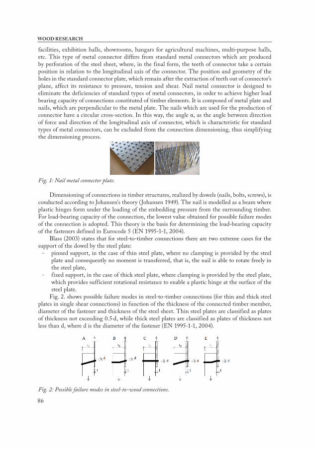
Blass (2003) states that for steel-to-timber connections there are two extreme cases for the support of the dowel by the steel plate:
- pinned support, in the case of thin steel plate, where no clamping is provided by the steel plate and consequently no moment is transferred, that is, the nail is able to rotate freely in the steel plate,
- fixed support, in the case of thick steel plate, where clamping is provided by the steel plate, which provides sufficient rotational resistance to enable a plastic hinge at the surface of the steel plate.
Fig. 2. shows possible failure modes in steel-to-timber connections (for thin and thick steel plates in single shear connections) in function of the thickness of the connected timber member, diameter of the fastener and thickness of the steel sheet. Thin steel plates are classified as plates of thickness not exceeding 0.5.d, while thick steel plates are classified as plates of thickness not less than d, where d is the diameter of the fastener (EN 1995-1-1, 2004).
Fig. 2: Possible failure modes in steel-to-wood connections.
87
Vol. 63 (1): 2018
According to Johnsson (2004), in the case of nailed connections, if the thickness of the steel plate is less than half of the diameter of the nail, no plastic hinge will form and the resistance of the connection will be lower, in relation to the connection realized by steel plate of thickness larger than the diameter of the nail. As stated by Johnsson (2004), a failure mode E is desirable, characterized by ductile behaviour, which provides energy dissipation in the case of earthquake loading and thus greater safety of timber structure. In this respect, in the case of the connections realized by thin steel plate it is possible to achieve the rigidity of the connection of nails and sleet plate by welding of the nails head to the steel plate, and thus to prevent the rotation of nails and to achieve ductility of connection. In this way, the behaviour of a connection that resembles that of the punched metal plate connection can be achieved. The punched metal plate, formed by the perforation of the metal sheet and extraction of the teeth, which provides the rigid connection of teeth to steel plate, is characterized by semi-rigid behaviour (Kevarinmäki 2000), relatively higher displacements (approximately 3.0 mm), but also higher ductility, which contributes to better behaviour of the entire structure under the failure conditions.
Connection of timber elements realized by nail metal connector has similarities with connection realized in artisanal and semi-industrial way, using nails and both sides positioned metal plates. The difference between these connections is in the technique of installation of nails into the wood. In artisanal way the nails are manually installed, in semi-industrial way the nails are installed by pneumatic gun, while in the case of nail metal connector they are installed in wood by hydraulic presses, as a part of industrial process. Considering the previous ascertainment, the load-bearing capacity of structural timber member connections realized by nail metal connector plates could be determined analytically, according to the concept of limit bearing capacity, in accordance with the provisions of Eurocode 5 (EN 1995-1-1, 2004). The concept of limit bearing capacity is based on the partial safety factors and analytical expressions obtained from specific experimental tests.
The proposed concept of nail metal connector plate allows the nails either to be or not to be rigidly joined to connector’s plate, and, in this context, the load-bearing capacity of this type of fastener can be analysed (Tekić 2007). For this purpose, the experimental tests have been carried out, with the aim of determining to what extent the degree of nail-to-plate connection rigidity affects the load-bearing capacity of structural timber member connections realized by nail metal connector plates. The nail connector plates which are subjected to experimental testing are made in two variants. In the first variant, the nails are embedded in the pre-drilled holes in steel plate. In the second variant, the nails are embedded in the pre-drilled holes in steel plate and then the head of the nail is welded to the steel plate by its circumference, which provides a moment resisting connection. Experimental testing was conducted by loading of multiple samples up to the limit bearing capacity of connection realized by nail metal connector plate, in accordance with the provisions of Eurocode 5.
Dimensioning of the connections formed by metal connectorsThe nail metal connector plate anchorage capacity is defined on the basis of EN 1075 (1999)
and EN 28970 (1991) standarts, in function of the limit load, effective connector area and wood density:
, (MPa) (1)
where: fa,α,β - limit plate anchorage capacity for given angles α and β (for one connector in connection),
88
WOOD RESEARCH
α - angle between direction of force and direction of the longitudinal axis of connector,β - angle between direction of force and direction of the longitudinal axis of timber member,Fa,α,β,max - maximum load,Aef - effective connector area,ρk - characteristic density of wood, for certain class of wood,ρ - density of wood, for the test sample,c - dimensionless coefficient.
MATERIAL AND METHODS
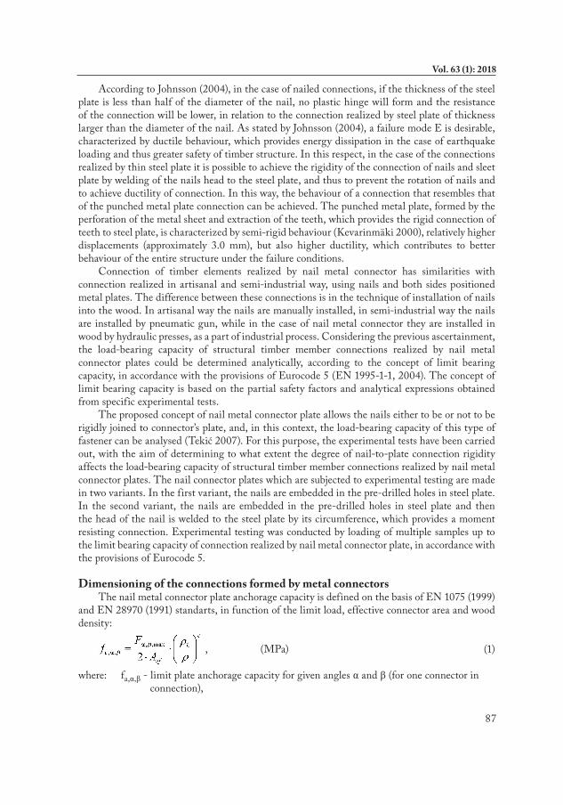
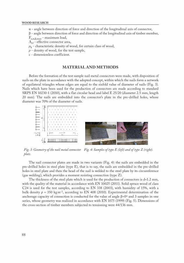
Before the formation of the test sample nail metal connectors were made, with disposition of nails on the plate in accordance with the adopted concept, within which the nails form a network of equilateral triangles whose edges are equal to the sixfold value of diameter of nails (Fig. 3). Nails which have been used for the production of connectors are made according to standard SRPS EN 10230-1 (2010), with a f lat circular head and label E 25/20 (diameter 2.5 mm, length 20 mm). The nails are embedded into the connector’s plate in the pre-drilled holes, whose diameter was 70% of the diameter of nails.
Fig. 3: Geometry of the nail metal connector plate.
Fig. 4: Samples of type E (left) and of type Z (right).
The nail connector plates are made in two variants (Fig. 4): the nails are embedded in the pre-drilled holes in steel plate (type E), that is to say, the nails are embedded in the pre-drilled holes in steel plate and then the head of the nail is welded to the steel plate by its circumference (gas welding), which provides a moment resisting connection (type Z).
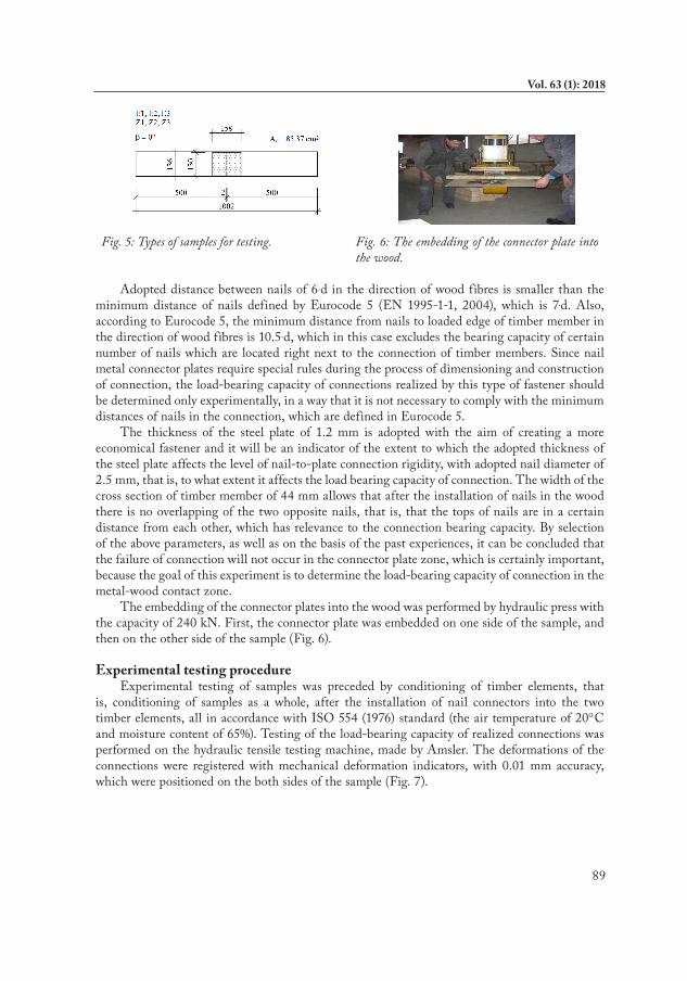
The thickness of the steel plate which is used for the production of connectors is d=1.2 mm, with the quality of the material in accordance with EN 10025 (2011). Solid spruce wood of class C24 is used for the test samples, according to EN 338 (2003), with humidity of 15%, with a bulk density ρ = 350 kg.m-3, according to EN 408 (2010). Experimental determination of the anchorage capacity of connection is conducted for the value of angle β=0º and 3 samples in one series, whose geometry was realized in accordance with EN 1075 (1999) (Fig. 5). Dimensions of the cross-section of timber members subjected to tensioning were 44/136 mm.
89
Vol. 63 (1): 2018
Fig. 5: Types of samples for testing. Fig. 6: The embedding of the connector plate into
the wood.
Adopted distance between nails of 6.d in the direction of wood fibres is smaller than the minimum distance of nails defined by Eurocode 5 (EN 1995-1-1, 2004), which is 7.d. Also, according to Eurocode 5, the minimum distance from nails to loaded edge of timber member in the direction of wood fibres is 10.5.d, which in this case excludes the bearing capacity of certain number of nails which are located right next to the connection of timber members. Since nail metal connector plates require special rules during the process of dimensioning and construction of connection, the load-bearing capacity of connections realized by this type of fastener should be determined only experimentally, in a way that it is not necessary to comply with the minimum distances of nails in the connection, which are defined in Eurocode 5.
The thickness of the steel plate of 1.2 mm is adopted with the aim of creating a more economical fastener and it will be an indicator of the extent to which the adopted thickness of the steel plate affects the level of nail-to-plate connection rigidity, with adopted nail diameter of 2.5 mm, that is, to what extent it affects the load bearing capacity of connection. The width of the cross section of timber member of 44 mm allows that after the installation of nails in the wood there is no overlapping of the two opposite nails, that is, that the tops of nails are in a certain distance from each other, which has relevance to the connection bearing capacity. By selection of the above parameters, as well as on the basis of the past experiences, it can be concluded that the failure of connection will not occur in the connector plate zone, which is certainly important, because the goal of this experiment is to determine the load-bearing capacity of connection in the metal-wood contact zone.
The embedding of the connector plates into the wood was performed by hydraulic press with the capacity of 240 kN. First, the connector plate was embedded on one side of the sample, and then on the other side of the sample (Fig. 6).
Experimental testing procedureExperimental testing of samples was preceded by conditioning of timber elements, that
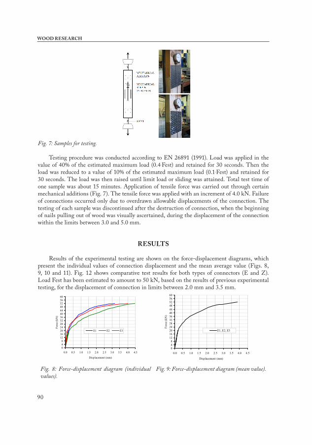
is, conditioning of samples as a whole, after the installation of nail connectors into the two timber elements, all in accordance with ISO 554 (1976) standard (the air temperature of 20°C and moisture content of 65%). Testing of the load-bearing capacity of realized connections was performed on the hydraulic tensile testing machine, made by Amsler. The deformations of the connections were registered with mechanical deformation indicators, with 0.01 mm accuracy, which were positioned on the both sides of the sample (Fig. 7).
90
WOOD RESEARCH
Fig. 7: Samples for testing.
Testing procedure was conducted according to EN 26891 (1991). Load was applied in the value of 40% of the estimated maximum load (0.4.Fest) and retained for 30 seconds. Then the load was reduced to a value of 10% of the estimated maximum load (0.1.Fest) and retained for 30 seconds. The load was then raised until limit load or sliding was attained. Total test time of one sample was about 15 minutes. Application of tensile force was carried out through certain mechanical additions (Fig. 7). The tensile force was applied with an increment of 4.0 kN. Failure of connections occurred only due to overdrawn allowable displacements of the connection. The testing of each sample was discontinued after the destruction of connection, when the beginning of nails pulling out of wood was visually ascertained, during the displacement of the connection within the limits between 3.0 and 5.0 mm.
RESULTS
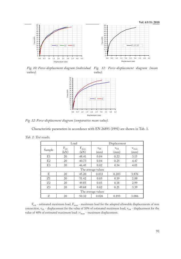
Results of the experimental testing are shown on the force-displacement diagrams, which present the individual values of connection displacement and the mean average value (Figs. 8, 9, 10 and 11). Fig. 12 shows comparative test results for both types of connectors (E and Z). Load Fest has been estimated to amount to 50 kN, based on the results of previous experimental testing, for the displacement of connection in limits between 2.0 mm and 3.5 mm.
048
12162024283236404448525660
0.0 0.5 1.0 1.5 2.0 2.5 3.0 3.5 4.0 4.5
Displacement (mm)
Forc
e (k
N)
E1 E2 E3
048
12162024283236404448525660
0.0 0.5 1.0 1.5 2.0 2.5 3.0 3.5 4.0 4.5
Displacement (mm)
Forc
e (k
N)
E1, E2, E3
Fig. 8: Force-displacement diagram (individual values).
Fig. 9: Force-displacement diagram (mean value).
91
Vol. 63 (1): 2018
048
12162024283236404448525660
0.0 0.5 1.0 1.5 2.0 2.5 3.0 3.5 4.0 4.5
Displacement (mm)
Forc
e (k
N)
Z1 Z2 Z3
048
12162024283236404448525660
0.0 0.5 1.0 1.5 2.0 2.5 3.0 3.5 4.0 4.5
Displacement (mm)
Forc
e (k
N)
Z1, Z2, Z3
Fig. 10: Force-displacement diagram (individual values).
Fig. 11: Force-displacement diagram (mean value).
048
12162024283236404448525660
0.0 0.5 1.0 1.5 2.0 2.5 3.0 3.5 4.0 4.5
Displacement (mm)
Forc
e (k
N)
E Z
Fig. 12: Force-displacement diagram (comparative mean value).
Characteristic parameters in accordance with EN 26891 (1991) are shown in Tab. 1.
Tab. 1: Test results.
Load Displacement
Sample Fest (kN)
Fmax (kN)
v01 (mm)
v04(mm)
vmax (mm)
E1 20 48.41 0.04 0.22 3.15E2 20 40.73 0.04 0.25 4.47E3 20 46.45 0.02 0.14 4.01
The average valuesE 20 45.20 0.033 0.203 3.876Z1 20 51.42 0.03 0.19 2.88Z2 20 49.85 0.03 0.18 2.99Z3 20 49.68 0.02 0.21 3.39
The average valuesZ 20 50.32 0.026 0.193 3.086
Fest - estimated maximum load, Fmax - maximum load for the adopted allowable displacements of mm connection, v01 - displacement for the value of 10% of estimated maximum load, v04 - displacement for the value of 40% of estimated maximum load i vmax - maximum displacement.
92
WOOD RESEARCH
DISCUSSION
Based on the given diagrams, the differences in displacements of connections realized by metal connectors of both types (E and Z), can be noted, for the same values of the applied load. For all samples, for the connector of type E and for the connector of type Z, minor differences in displacements to the extent of 0.4.Fest can be noted, whereupon the increase of deformation is higher for the connector of type E, relative to connector of type Z, for the same value of applied load.
Testing has shown that for type E connectors the failure takes place according to the failure mode A, and not B, which can be considered as expected failure in the connection of thin plate and nails of smaller lengths, given the penetration depth of s = 19 mm. In the case of the connectors of type Z, the failure takes place according to the failure mode D. The most ductile failure, characteristic for the failure mode E, was not achieved (Blass and Ehlbeck 1998). In the case of nails welded to the steel plate (type Z) it is shown that it is possible to partially utilize the plastic capacity of the nail and in the case of the connections realised by thin steel plate and nails of smaller lengths, where the nail bending angles are far less than 45° (Blass et al. 2001). Relatively short nails are used in the study, which approximately correspond to the length of the teeth of the punched metal connector plates (Tekić et al. 2015), resulting in failure with one plastic hinge at the surface of the steel plate (failure mode D). Higher load-bearing capacity and ductility of the connection could be achieved with further optimisation of the embedded length of the nail (Bruehl et al. 2011).
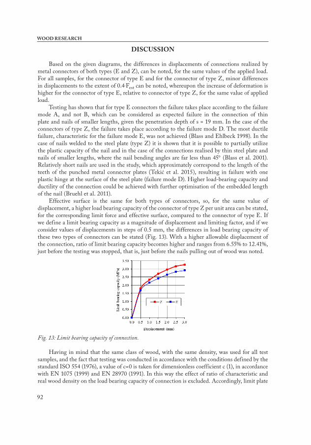
Effective surface is the same for both types of connectors, so, for the same value of displacement, a higher load bearing capacity of the connector of type Z per unit area can be stated, for the corresponding limit force and effective surface, compared to the connector of type E. If we define a limit bearing capacity as a magnitude of displacement and limiting factor, and if we consider values of displacements in steps of 0.5 mm, the differences in load bearing capacity of these two types of connectors can be stated (Fig. 13). With a higher allowable displacement of the connection, ratio of limit bearing capacity becomes higher and ranges from 6.55% to 12.41%, just before the testing was stopped, that is, just before the nails pulling out of wood was noted.
Fig. 13: Limit bearing capacity of connection.
Having in mind that the same class of wood, with the same density, was used for all test samples, and the fact that testing was conducted in accordance with the conditions defined by the standard ISO 554 (1976), a value of c=0 is taken for dimensionless coefficient c (1), in accordance with EN 1075 (1999) and EN 28970 (1991). In this way the effect of ratio of characteristic and real wood density on the load bearing capacity of connection is excluded. Accordingly, limit plate
93
Vol. 63 (1): 2018
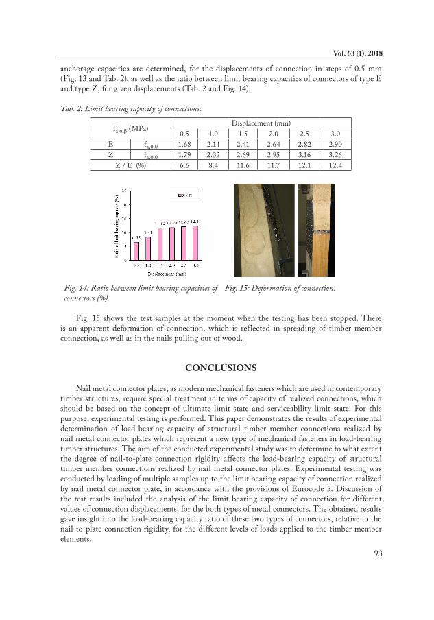
anchorage capacities are determined, for the displacements of connection in steps of 0.5 mm (Fig. 13 and Tab. 2), as well as the ratio between limit bearing capacities of connectors of type E and type Z, for given displacements (Tab. 2 and Fig. 14).
Tab. 2: Limit bearing capacity of connections.
fa,α,β (MPa)Displacement (mm)
0.5 1.0 1.5 2.0 2.5 3.0E fa,0,0 1.68 2.14 2.41 2.64 2.82 2.90Z fa,0,0 1.79 2.32 2.69 2.95 3.16 3.26
Z / E (%) 6.6 8.4 11.6 11.7 12.1 12.4
Fig. 14: Ratio between limit bearing capacities of connectors (%).
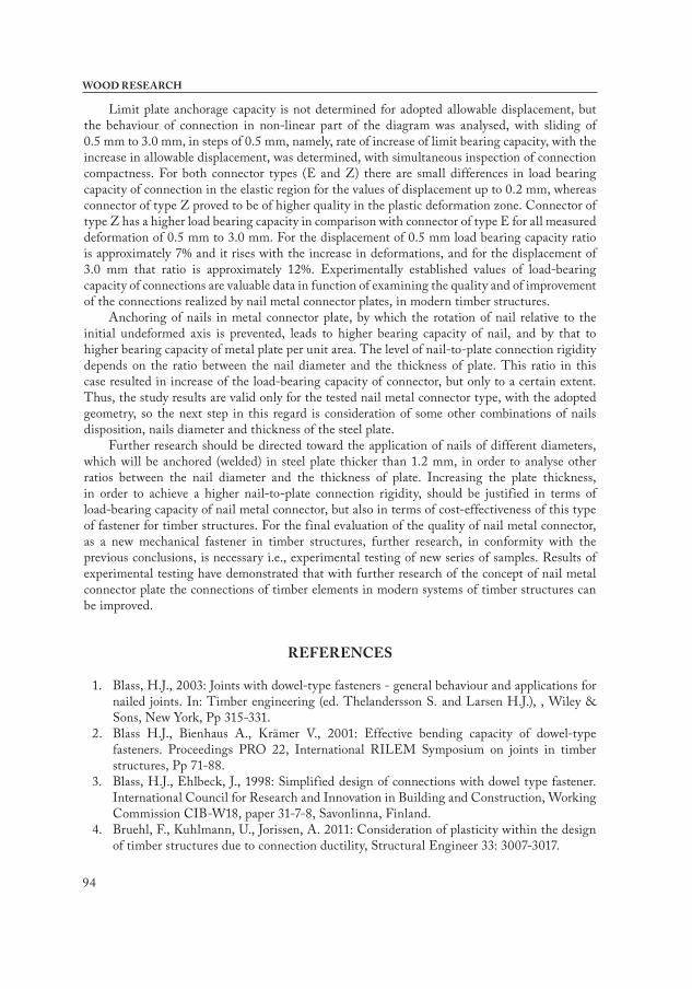
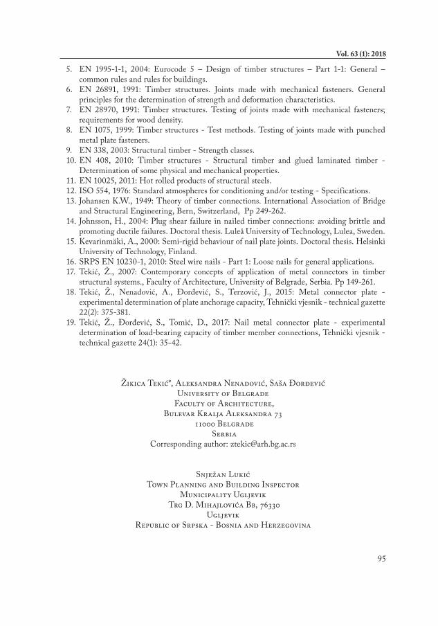
Fig. 15: Deformation of connection.
Fig. 15 shows the test samples at the moment when the testing has been stopped. There
is an apparent deformation of connection, which is reflected in spreading of timber member connection, as well as in the nails pulling out of wood.
CONCLUSIONS
Nail metal connector plates, as modern mechanical fasteners which are used in contemporary timber structures, require special treatment in terms of capacity of realized connections, which should be based on the concept of ultimate limit state and serviceability limit state. For this purpose, experimental testing is performed. This paper demonstrates the results of experimental determination of load-bearing capacity of structural timber member connections realized by nail metal connector plates which represent a new type of mechanical fasteners in load-bearing timber structures. The aim of the conducted experimental study was to determine to what extent the degree of nail-to-plate connection rigidity affects the load-bearing capacity of structural timber member connections realized by nail metal connector plates. Experimental testing was conducted by loading of multiple samples up to the limit bearing capacity of connection realized by nail metal connector plate, in accordance with the provisions of Eurocode 5. Discussion of the test results included the analysis of the limit bearing capacity of connection for different values of connection displacements, for the both types of metal connectors. The obtained results gave insight into the load-bearing capacity ratio of these two types of connectors, relative to the nail-to-plate connection rigidity, for the different levels of loads applied to the timber member elements.
94
WOOD RESEARCH
Limit plate anchorage capacity is not determined for adopted allowable displacement, but the behaviour of connection in non-linear part of the diagram was analysed, with sliding of 0.5 mm to 3.0 mm, in steps of 0.5 mm, namely, rate of increase of limit bearing capacity, with the increase in allowable displacement, was determined, with simultaneous inspection of connection compactness. For both connector types (E and Z) there are small differences in load bearing capacity of connection in the elastic region for the values of displacement up to 0.2 mm, whereas connector of type Z proved to be of higher quality in the plastic deformation zone. Connector of type Z has a higher load bearing capacity in comparison with connector of type E for all measured deformation of 0.5 mm to 3.0 mm. For the displacement of 0.5 mm load bearing capacity ratio is approximately 7% and it rises with the increase in deformations, and for the displacement of 3.0 mm that ratio is approximately 12%. Experimentally established values of load-bearing capacity of connections are valuable data in function of examining the quality and of improvement of the connections realized by nail metal connector plates, in modern timber structures.
Anchoring of nails in metal connector plate, by which the rotation of nail relative to the initial undeformed axis is prevented, leads to higher bearing capacity of nail, and by that to higher bearing capacity of metal plate per unit area. The level of nail-to-plate connection rigidity depends on the ratio between the nail diameter and the thickness of plate. This ratio in this case resulted in increase of the load-bearing capacity of connector, but only to a certain extent. Thus, the study results are valid only for the tested nail metal connector type, with the adopted geometry, so the next step in this regard is consideration of some other combinations of nails disposition, nails diameter and thickness of the steel plate.
Further research should be directed toward the application of nails of different diameters, which will be anchored (welded) in steel plate thicker than 1.2 mm, in order to analyse other ratios between the nail diameter and the thickness of plate. Increasing the plate thickness, in order to achieve a higher nail-to-plate connection rigidity, should be justified in terms of load-bearing capacity of nail metal connector, but also in terms of cost-effectiveness of this type of fastener for timber structures. For the final evaluation of the quality of nail metal connector, as a new mechanical fastener in timber structures, further research, in conformity with the previous conclusions, is necessary i.e., experimental testing of new series of samples. Results of experimental testing have demonstrated that with further research of the concept of nail metal connector plate the connections of timber elements in modern systems of timber structures can be improved.
REFERENCES
1. Blass, H.J., 2003: Joints with dowel-type fasteners - general behaviour and applications for nailed joints. In: Timber engineering (ed. Thelandersson S. and Larsen H.J.), , Wiley & Sons, New York, Pp 315-331.
2. Blass H.J., Bienhaus A., Krämer V., 2001: Effective bending capacity of dowel-type fasteners. Proceedings PRO 22, International RILEM Symposium on joints in timber structures, Pp 71-88.
3. Blass, H.J., Ehlbeck, J., 1998: Simplified design of connections with dowel type fastener. International Council for Research and Innovation in Building and Construction, Working Commission CIB-W18, paper 31-7-8, Savonlinna, Finland.
4. Bruehl, F., Kuhlmann, U., Jorissen, A. 2011: Consideration of plasticity within the design of timber structures due to connection ductility, Structural Engineer 33: 3007-3017.
95
Vol. 63 (1): 2018
5. EN 1995-1-1, 2004: Eurocode 5 – Design of timber structures – Part 1-1: General – common rules and rules for buildings.
6. EN 26891, 1991: Timber structures. Joints made with mechanical fasteners. General principles for the determination of strength and deformation characteristics.
7. EN 28970, 1991: Timber structures. Testing of joints made with mechanical fasteners; requirements for wood density.
8. EN 1075, 1999: Timber structures - Test methods. Testing of joints made with punched metal plate fasteners.
9. EN 338, 2003: Structural timber - Strength classes.10. EN 408, 2010: Timber structures - Structural timber and glued laminated timber -
Determination of some physical and mechanical properties.11. EN 10025, 2011: Hot rolled products of structural steels.12. ISO 554, 1976: Standard atmospheres for conditioning and/or testing - Specifications.13. Johansen K.W., 1949: Theory of timber connections. International Association of Bridge
and Structural Engineering, Bern, Switzerland, Pp 249-262.14. Johnsson, H., 2004: Plug shear failure in nailed timber connections: avoiding brittle and
promoting ductile failures. Doctoral thesis. Luleå University of Technology, Lulea, Sweden.15. Kevarinmäki, A., 2000: Semi-rigid behaviour of nail plate joints. Doctoral thesis. Helsinki
University of Technology, Finland. 16. SRPS EN 10230-1, 2010: Steel wire nails - Part 1: Loose nails for general applications.17. Tekić, Ž., 2007: Contemporary concepts of application of metal connectors in timber
structural systems., Faculty of Architecture, University of Belgrade, Serbia. Pp 149-261.18. Tekić, Ž., Nenadović, A., Đorđević, S., Terzović, J., 2015: Metal connector plate -
experimental determination of plate anchorage capacity, Tehnički vjesnik - technical gazette 22(2): 375-381.
19. Tekić, Ž., Đorđević, S., Tomić, D., 2017: Nail metal connector plate - experimental determination of load-bearing capacity of timber member connections, Tehnički vjesnik - technical gazette 24(1): 35-42.
Žikica Tekić*, Aleksandra Nenadović, Saša ĐorđevićUniversity of Belgrade
Faculty of Architecture,Bulevar Kralja Aleksandra 73
11000 Belgrade Serbia
Corresponding author: [email protected]
Snježan LukićTown Planning and Building Inspector
Municipality Ugljevik Trg D. Mihajlovića Bb, 76330
UgljevikRepublic of Srpska - Bosnia and Herzegovina

96
WOOD RESEARCH