Embed Size (px)
Citation preview

Wood Science and Technology Vol. 9 (1975) p. 129-144 �9 by Springer-Verlag 1975
N a i l e d W o o d J o i n t s u n d e r C o m b i n e d L o a d i n g
By A. Louis DeBonis and J. Bodig*
Department of Forest and Wood Sciences, Colorado State University, Fort Collins, Col.
Summary. A new testing apparatus was designed and a test method developed to enable the application of axial loads, lateral loads, and controlled ratios of axial to lateral loads to nailed wood joints. The effect of axial load components on ultimate lateral load, joint deformations and several slip moduli were evaluated. These load-slip parameters were determined for three species of wood, three depths of nail penetration, and eight angles of load application. Several basic equations were examined to quantitatively describe the effect of combined axial and lateral loads. These included Hankinson's formula, a modified stress interaction formula, and a semi-log curve fitting process. Hankinson's formula proved to be a poor equation to describe the combined load effect, pro- ducing errors in excess of 500 percent in some cases. The stress interaction formula modified with a sine function produced an accurate method for describing ultimate load with errors be- low 15 percent. This is recommended as a design equation for nailed joints loaded in a com- bined manner. The use of a semi-log curve fitting process and a simple linear regression made it possible to describe the effect of axial load components on stiffness parameters of nailed joints.
Literature review
Current design practices with nailed joints are categorized into withdrawal and
lateral load conditions. In past investigations, these two types of nailed joints have
been evaluated differently. In the case of withdrawal resistance only ultimate load
is determined [Perkins 1971; U.S. Dept. Agr. 1965]. However, for lateral shear
resistance, the entire non-linear load-deformation curve is studied.
The joint displacement for lateral load is commonly called interlayer slip and results
from the semi-rigid nature of the connection. Laterally loaded nailed joints fail by
both yielding of the nail in bending and failure of the wood in bearing along the
nail shank [Nor6n 1962]. Therefore, the non-linear effect is a function of the load-
slip characteristics of the fastener-wood combination.
Some investigators have attempted to describe theoretically the load-slip behavior
of nailed joints [Kuenzi 1955; Wilkinson 1972] while others used empirical equations
for the same purpose !Foschi 1973; Mack 1966; Morris 1970; Vanderbilt et al. 1974;
Wilkinson 1972].
Both withdrawal and lateral resistance are affected by a number of factors. These
include specific gravity [Brock 1957, U.S. Forest Prod. Lab. 1931 ] and moisture
content [Morris 1970; Stern 1964] of the material to be fastened, depth of penetra-
* The authors wish to acknowledge the National Science Foundation for financial support under NSF Grant GK-30853 entitled "A Rational Analysis and Design Procedure for Wood Joist Floor Systems" and the Mclntire-Stennis Cooperative Forestry Research Program for additional financial support.

130 A.L. DeBonis and J. Bodig Nailed wood joints under combined loading
tion, diameter [Albert, Johnson 1967; U.S. Forest Prod. Lab. 1931], point and shank characteristics [Scholten 1962; Stern 1956] of nails, and modifications such as clinching and preboring [Stern 1964; U.S. Dept. Agr. 1974]. Several investigators have discussed the fact that nailed joints are often loaded in a combined axial and lateral manner [Hoyle 1972; Stern 1962; Vanderbilt et al. 1974]. The extent of the work carried out on this topic, however, amounts to the general behavior of toe-nailed joints [Scholten 1965; Scholten, Molander 1950], slant driven
nails [Stern 1952], and overall comparisons of racked wall frames constructed with various types of nails [Stern 1950].
It has been suggested that in cases where combined load situations exist, both with- drawal and lateral load components be taken into account [Hoyle 1972]. However,
the only design consideration presently given to this combined load situation in the
U.S. is for the case of toe-nailed joints in which the design load is reduced in rela-
tion to the allowable loads [National Forest Prod. Assoc. 1973]. Current design methods employed for multi-layered semi-rigidly connected structural
wood members often overlook the interlayer slip effect. For example, consider the case of a nailed wood joist floor system. The behavior of such a system may be
thought of as consisting of the actions of T-beams along the joist and sheathing
beams perpendicular to the joist. The T-beam possesses incomplete composite action
due to the semi-rigid nail connections. For the case when concentrated loads are applied to such a floor system, the nails are loaded both in lateral and axial manners [Vanderbilt et al. 1974]. Although much information is available on the behavior of nailed joints loaded only in an axial [Perkins 1971; U.S. Dept. Agr. 1965; U.S. Forest Prod. Lab. 1931; West- man, McAdoo 1969] or in a lateral [Foschi 1973; Mack 1960, 1966; Morris 1970] manner, virtually no quantitative data are available concerning the behavior of nailed
joir/ts in combined loading. Therefore, this study was designed to investigate the effect
of combined axial and lateral loading of nailed joints. With knowledge of the com-
bined load effect on slip behavior, coupled with its effect on ultimate load, present
design techniques may be improved.
Development of testing apparatus
Previously used test specimens for determining withdrawal or lateral shear resistance
are not satisfactory to evaluate the combined load effect. Since different types of test specimens are used in each procedure the need for a new test method is apparent. An integral part of this study was the design and construction of a new testing apparatus which would permit the application of controlled ratios of withdrawal to lateral loads to a uniform test specimen with the use of a single apparatus. To achieve these goals a modified version of an apparatus developed by Munse and Cox [ 1956] was used. These authors used their apparatus previously to study the
ultimate strength of rivets under combined tension and shear loads. Fig. 1 illustrates the detailed design of the apparatus used in this study. It can be seen in Fig. I a that when a tensile load is applied through the paired loading holes

A. L. DeBonis and J. Bodig Nailed wood joints under combined loading 131
Fig. 1.
J A
0.50"
8
2- . . . . . ~__
b
Combined loading apparatus. (a) front view; (b) side view
_i
numbered (1), which are parallel to the longitudinal axis of the nail, an axial load results. By rotating the apparatus 90 degrees counter-clockwise and applying the tensile load through the paired loading holes numbered (8), orthogonal to the longitudinal axis of the nail, a lateral load is produced. Application of the same type of load through any of the other paired loading holes permits the application of various controlled ratios of axial to lateral load. Thus with the use of this test- ing apparatus it is possible to attain the desired loading conditions with a uniform test specimen. The test specimen illustrated in Fig. 2 was placed between the loading plates (A, B, C and D) of Fig. 1 b and pressure was applied to the specimen (d), through the pressure plates (c), by tightening the pressure nuts and bolts (a) and (b), respectively. These pressure plates were located 2.0 in. from the nail and therefore should have little influence on the load-slip behavior of the joint. Since in the most general case both axial and lateral load components were applied to the nailed specimen, it was necessary to measure the deformations both perpendic-
Vuri~Qble thickness / ~ - - ~ --~"--1- -J-1 i x
~F ~i ~ il [ I Penetp tr0'
Fig. 2. Generalized test specimen

132 A.L. DeBonis and J. Bodig Nailed wood joints under combined loading
Fig. 3. Assembled testing apparatus loaded in an axial load situation
ular and parallel to the longitudinal axis of the nail (X and Y axes respectively).
This was accomplished by using two sets of two linear variable differential trans-
formers (LVDTs). The LVDT arrangement can be seen in Fig. 3. The vertically
aligned LVDTs measured the relative axial deformation while the horizontally aligned
Fig. 4.
LoGd [[b~
~- ?-/ //---7~-/ / / ~ / /
DeformQtien [in~]
Typical load-slip curve illustrating parameters evaluated

A. L. DeBonis and J. Bodig Nailed wood joints under combined loading 133
LVDTs measured the relative lateral deformation of the plates holding the specimen.
The testing apparatus was designed to be symmetrical about its principal axes.
Therefore, this LVDT arrangement not only existed on loading plates (A) and (B),
as pictured here, but also on loading plates (C) and (D). The output from both
vertically oriented LVDTs was electronically averaged as was that from both hori-
zontal LVDTs. This averaging technique provided the opportunity to minimize
error introduced by any unknown bending of the testing apparatus about its axes of symmetry.
Two X-Y recorders were used to record separately the relationships between the
applied load and the axial and lateral deformation. The electronic signal for the
load was obtained through the load cell of an Instron testing machine. A typical
load-slip curve is shown in Fig. 4.
Experimental procedure
To effectively evaluate the influence of Wood specific gravity three species, cover-
ing a wide density spectrum, were used. Three nail penetration depths were selected to correspond to 6, 10, and 14 times the diameter of an eight penny common wire
nail (~ = 0.131 in.). The load angle variation ranged from lateral load (0 degrees) to axial load (90 degrees, withdrawal) with six intermediate controlled ratios. Since the experimental design was a factorial design with one replication of each test, a total of 144 nailed joints as tested. The moisture content, nail size, and grain direction were held constant. Eight penny common wire nails were used, since this is the nail size most commonly used in wood frame construction. To minimize variation, the nails were driven in the radial direction (tangential face) of the specimens. Also, each subsequent test specimen was taken in line along the plank from which it was cut in an attempt to minimize material variability between replications. All materials were conditioned in a room
set at 70 ~ and a relative humidity of 66 percent. Due to the fact that the Engel-
mann spruce and Douglas-fir specimens were conditioned from dryeI, and the oak specimens from wetter conditions than 12 percent, they did not attain the same
equilibrium moisture content in the conditioning room. This can be seen in Table 1.
The oven-dry method was used for the moisture content determination. Specific gravity based on air-dry volume was determined and converted to specific gravity based on green volume [Brown, Panshin, Forsaith 1952].
Table I. Material properties
Species Ave. Ave. specific moisture gravity content
Engelmann spruce 0.314 10.78 Douglas-fir 0.440 9.92 Red oak 0.604 15.74

134 A.L. DeBonis and J. Bodig Nailed wood joints under combined loading
Each test was carried out on a predetermined time schedule to eliminate the in-
fluence of time dependency. An arbitrary period of one hour between specimen
nailing and testing was chosen. After the specimens were cut to their required
dimensions, the component parts were nailed together with use of a nailing jig and
placed in polyethylene bags until testing. All recording apparatus was balanced and the nailed specimen was placed on loading plates (C) and (D) which were resting on an alignment base. Loading plates (A)
and (B) were then placed on top of the specimen, the loading grips positioned in
the appropriate loading holes and the apparatus tightened with a torque wrench
preset to apply sufficient pressure to avoid slippage of the specimen in the appara- tus. With the use of the alignment base the origins of the reference coordinate systems of the specimen, loading apparatus and axes of deformation were matched. Alignment was transferred from the alignment base to the loading plates through the aligmnent holes (f). The entire apparatus was then clamped together to keep it rigid in order to assure that the nailed joint would not sustain a pre-load during transferral of the assembled testing apparatus from the alignment base to the testing
machine. After placement of the apparatus in the testing machine, the clamps were removed and the load was applied at a rate of 0.1 inch per minute. All tests were
carried out to ultimate load. After the specimens were removed from the testing apparatus the moisture content
and specific gravity of the specimens were determined. From each test two load-
slip curves were obtained, one relating the applied angular load to the deformation
in the axial (Y) direction and the other relating the applied angular load to the
deformation in the lateral (X) direction. Fig. 4 illustrates a generalized load-slip
curve from which several parameters were evaluated. The parameters evaluated are
listed in Table 2 and were determined by applying the formulas given as:
Pu KTi = U---~. ' (1)
where K T = tangent modulus (lb./in.),
Pu = ultimate load (lb.), U = deformation measured by projected tangent line (in.),
i = initial load, one-third ultimate load, two thirds ultimate load.
Table 2. Load slip parameters evaluated
Pu KS1/3 KS2/3 KS u KT I KTI[3 KT2/3
Ultimate load Secant modulus at ~- ultimate load Secant modulus at ~- ultimate load Secant modulus at ultimate load Initial tangent modulus Tangent modulus at ~r ultimate load Tangent modulus at ~- ultimate load

A. L. DeBonis and J. Bodig Nailed wood joints under combined loading 135
PJ (2) KS = - - A i '
where KS = secant modulus (lb./in.), P = load at j (lb.), A --- deformation (in.), j = one-third ultimate load, two-thirds ultimate load, ultimate load.
In all of the analysis techniques, except for the determination of the effect of axial
load component on the lateral stiffness, the deformation parallel to the applied load,
U a was used in solving (1) and (2). This was clone by a simple vector relationship
ua = ~ , (3)
where U x = deformation measured in the lateral direction Uy = deformation measured in the axial direction.
In the case of axial load effects on lateral stiffness the lateral load component and
lateral deformations were used.
Analysis of variance
To evaluate the significance of the selected variables on a number of the load-slip parameters, analyses of variance were performed on the data. It can be seen in
Table 3 that the variables used in this study significantly affect all load-slip para-
meters. The interaction of specific gravity and depth of penetration also significantly
affects all values. When angular variation is included in the interaction, several
significant values still appear. This illustrates the fact that for several, properties an
interaction exists between all three variables. The meaning of this interaction is
that a given load-slip parameter is affected differently for a given species, depth of nail penetration, and angle of the applied load. Therefore, for further analysis, none of the variables may be combined and each series of data has to be evaluated
independently. I t was decided to omit the evaluation of the initial tangent modulus
from any further analysis since the evaluation of this property is very" difficult.
A small error in deformation measurement produced large differences in the final
tangent modulus value.
Hankinson's formula
Several methods of analysis were employed to find the most suitable means of des- cribing the angular variation of given slip-curve parameters. One method assumed the existence of an empirical relationship, between the evaluated parameters and the angle of load given by Hankinson's formula [Hankinson 1921]. By recalling the angular variation as illustrated by Fig. 2 it can be seen that Hankinson's formula may be expressed as
N x Ny Na = N x sinZa + Ny cos20~ ' (4)

Tab
le 3
. S
um
mar
y o
f th
e an
aly
ses
of
var
ian
ce r
esu
lts
for
the
load
-sli
p p
aram
eter
s
Var
iab
le
D.F
. P
u K
S 1
[3
K S
2]3
K
S u
K
T 1
K
T 1
]3
K T
2/3
F v
alu
e 4
66
.20
5
.55
7
.61
1
7.9
4
4.3
5
10
.01
8
.15
1 2
sig
nif
ican
ce
**
**
**
**
, **
**
lev
el
F v
alu
e 2
7.8
8
15
.07
3
5.8
9
16
.23
6
.75
1
9.6
8
28
.63
2 2
sig
nif
ican
ce
**
**
**
**
**
**
**
leve
l
F v
alu
e 3
7.5
6
18
.35
4
5.1
6
40
.66
2
.84
2
6.8
8
42
.94
3 7
sig
nif
ican
ce
**
**
**
**
. **
**
lev
el
F v
alu
e 1
1.5
2
4.4
7
7.1
9
9.4
4
9.0
0
4.7
6
2.6
0
1,2
4
sig
nif
ican
ce
**
**
**
**
**
**
, le
vel
F v
alu
e 3
.35
1.
45
1.2
8
3.2
0
6.5
1
1.6
2
1.3
7
1, 3
14
si
gn
ific
ance
**
N
.S.
N.S
. **
**
N
.S.
N.S
. le
vel
F v
alu
e 1.
65
2.9
1
6.1
6
5.8
3
2.5
9
3.8
6
6.8
2
2, 3
14
si
gn
ific
ance
N
.S.
**
**
**
**
**
**
lev
el
F v
alu
e 4
.06
1.
29
1.76
3
.47
1
0.5
0
1.3
3
1.67
1, 2
, 3
28
sig
nif
ican
ce
**
N.S
. *
**
**
N.S
. *
lev
el
Var
iab
les:
1
spec
ific
gra
vit
y
Sig
nif
ican
ce l
evel
: N
.S.
no
n-s
ign
ific
ant
2 d
epth
of
pen
etra
tio
n
* 5
%
3 an
gle
of
load
**
1%
A. L. DeBonis and J. Bodig Nailed wood joints under combined loading 137
where
N a = load-slip parameter at angle a,
N x = load-slip parameter perpendicular to the axis of the nail, Ny = load-slip parameter parallel to the axis of the nail,
a = angle between the direction of load and the direction of the plane of the joint.
Two statistical parameters were used, allowing the evaluation of the applicability of
any prediction equation to actual experimental data [Goodman, Bodig 1971]. These
are the standard error of estimate (S.E.E.) and the mean deviation (M.D.). The
smaller the values of these parameters the better the fit of the data to the predicted
line. In addition, the sign of the mean deviation illustrates whether the majority of
the actual points lie above or below the predicted line.
Analysis of ultimate load by Hankinson's formula produced the best results with
S.E.E. ranging from 40 to 70 percent. Analysis of all other parameters produced
much larger errors with S.E.E. values as high as 800 %. From this it was concluded
that Hankinson's formula is an extremely poor method of describing the effect of
combined axial and lateral loading of nailed joints.
The basis of Hankinson's formula, centers around grain angle variation for which this emperical relationship is well adapted. Although through the angular variation the nails are loaded at different grain angles of the wood, they do not seem to have the same mechanism governing their behavior as does the crushing strength of wood. The magnitude of errors obtained substantiates this view.
Interaction formula
The second method used to describe the effect of angular variation on the ultimate load is a modified stress interaction formula. The general form of this equation is presently used in the design of structures for evaluating the effects of combined stresses in structural members. For the case of combined nail force effects, the
interaction concept may be expressed as
Pax Pay = p x + 1.0, (s)
where
Pax = x component of the toad at angle a,
P a y = Y component of the load at angle a, Px = load applied perpendicular to the nail axis,
Py = load applied parallel to the nail axis.
Considering the basic vector relationships, the component of Pa in the X direction is given by
Pax = Pa (cos a) (6)
and the component of Pa in the Y direction is given by
P a y = Pa (sin a) (7)
138 A.L. DeBonis and J. Bodig Nailed wood joints under combined loading
Substitution of (6) and (7) into (5) gives
Pa(cosa______) + Pa(sin a) _ 1.0. (8) Px Py
Present use of the concept of stress interaction would entail restriction in the size of the components of Pa such that a maximum value of 1.0 on the right hand side of (8) would be obtained. However, in the case of this study it was desired to determine what values of the sum on the left hand side of (8) would be produced by substitution of actual experimental values for Pa, Px and Py. This was accom-
plished by removal of the restraint of 1.0 (8)and assigning it the variable value of Z a. Therefore, (8) can be rewritten as
Pa (cos a) Pa (sin a) p------~ + py = Za (9)
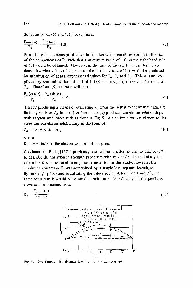
thereby producing a means of evaluating Z a from the actual experimental data. Pre- liminary plots of Z a from (9) vs. load angle (a) produced curvilinear relationships with varying amplitudes such as those in Fig. 5. A sine function was chosen to des-
cribe this curvilinear relationship in the form of
Z a = 1.0 + K sin 2 a , (10)
where
K = amplitude of the sine curve at a = 45 degrees.
Goodman and Bodig [ 1971] previously used a sine function similar to that of (10)
to describe the variation in strength properties with ring angle. In that study the
values for K were selected as empirical constants. In this study, however, the
amplitude correction K, was determined by a simple least squares technique.
By rearranging (10) and substituting the values for Z a determined from (9), the
value for K which would place the data point at angle a directly on the predicted
curve can be obtained from
Z a - 1.0 K a = s i n 2 a ' (11)
Fig. 5.
2.5 I I ] I �9 --.-- Enge{mann spruce at 14r penetration I
Z~=1.0+0.%4 sin2o~ r=0.s .... OouglQs-fir ot 14r penetrotion
7,0 Z~=1.0+0.151 sin2o~ r(NS) - - F(Z~ =1.0+Ksin2~ I ,}/ �9
, - - - =1.o _ 1.5 ~
2
1.o i 0,500 15 ~ 30" 45" 60 ~ 75" 00 ~
Sine function for ultimate load from interaction concept
A. L. DeBonis and J. Bodig Nailed wood joints under combined loading 139
where
K a = amplitude at 45 degrees which would place the actual data point at angle a
directly on the predicted line.
For the fmal K value, a weighted average was choosen with tile weighting constant,
Wa, corresponding to the error probability. This in equation form is
_+ (• K
-+ (w-5 J (12)
Extremely good results were obtained in attempting to describe ultimate load using
the stress interaction concept as can be seen in Table 4. Present design practices
using the stress interaction concept do not permit values to exceed 1.0. This would
suggest the use of (9) rather than (10). In this study, the correlation coefficient was
computed to determine how much better the derived sine function fit the data than
the assumption of 1.0 which is a straight line (Fig. 5).
By referring to Table 4 it can be seen that in the case of ultimate load S.E.E. values
range from 6.84 percent to 14.91 percent and M. D. values range from - 1.64 per-
cent to - 4 . 3 5 percent. In only two cases were the r values found non-significant.
In each of these cases the amplitude correction to the sine curve (K) is extremely
small. At very low amplitudes it is not unreasonable to expect that the data fit an
equation for a straight line as well as that for the sine curve. However, in these
cases, since the S.E.E. and M.D. are extremely small, the sine function modification
of the stress interaction formula produces little if any error over the straight-line
prediction. Fig. 5 illustrates two sets of typical data for ultimate load and shows
the scatter of data about the line predicted by the sine function. In the case of
Table 4. Summary of amplitude corrections and statistical evaluation of stress interaction con- cept for ultimate load
S.E.E. M.D. Penetration K r % %
Engelmann spruce
A (6 r 1.406 14.91 - 2.65 .94 B (10 r 0.542 11.80 - 3.04 .85 C (14r 0.644 11.22 - 2.50 .91
Douglas-fir
A (6r 0.222 12.02 - 2,91 N.S. B (10r 0.924 11.69 - 2.33 .95 C (t4 r 0.15t 9.98 - 4.35 N.S.
Red oak
A (6 r 0.236 6.84 - 1.64 .89 B (10 ~) 0.205 7.01 - 2.02 .74 C (14r 0.485 10.10 - 2.42 .84
* Data for other toad-slip curve parameters available from DeBonis [19741

140 A.L. DeBonis and J. Bodig Nailed wood joints under combined loading
Engelmann spruce at 14 ~ penetration a large K was obtained and thus a good r
value. For the case of Douglas-fir at 14 ~ penetration a small K was obtained and
thus a poor r value.
For purposes of accuracy it is suggested that the interaction concept with the sine
function be used for describing ultimate load when the load has been applied at
various angles. However, for design purposes the interaction formula with 1.0 may be used with the understanding that this is a conservative approach.
This type o f curve was fit to the data for both joint deformations and the various slip moduli. Generally the values o f S.E.E. and M.D. were somewhat higher than
those given in Table 4 and were in the range o f 50 percent for S.E.E. and - 30 per- cent for M.D.
Semi-log relationship
Preliminary plots of data revealed that a nonlinear relationship could be expected
between the slip moduli and the angular variation. To describe these data in a simple
linear form a logarithmic transformation was used. This involved the nonlinear
reduction of the magnitude of the slip curve parameters by converting them to
their logarithmic counterparts. The generalized equation thus used to describe the
data is given by
Log N a = a + b (a) , (13)
where
N a = load-slip parameter at angle a,
a, b = equation constants.
The line obtained by this equation was fitted to the data by means of a simple linear
regression. Table 5 lists the values obtained for the equation constants (a, b), correla-
tion coefficient (r), and standard error of estimate (S.E.E.) for Douglas-fir at 10 (l)
penetration. By referring to Fig. 6 it can be seen that as the angle increases from 0 to 90 degrees,
that is when the load shifts from lateral shear to withdrawal, the slip moduli values
also increase. Since the values o f S.E.E. are very low and most of the r values
Table 5. Example of equation parameters obtained by semi-log curve fitting for Douglas-fir at 10 r penetration
I log lb./in.~ S.E.E. Penetration Parameter a (log lb./in.) b ~ ] r %
B (10 ~)
KS1/3 4.121 .0076 .94 2.09 KS2/3 3.582 .0115 .98 2.00 KS u 2.933 .0149 .97 3.92 K T 1/3 3.756 .0089 .98 4.29 KT2/3 3.024 .0155 .97 3.56
* Complete data available from DeBonis [19741

A. L. DeBonis and J. Bodig Nailed wood joints under combined loading 141
Fig. 6.
s0 ! I 2 . - - - < I i I I | . f " v I
=40 L I . y " " . . - ' ~ I 1 . 1 "
? o . ~ ~ I ! - - ~ - - ~ " I o �9 / i
I b J - / i �9 cso
�9 F- I . . . . r
0 ~ q5 ~ 30 ~ 45 ~ SO ~ 75 o 90 ~
Log slip modulus vs. angular variation for Douglas-fir at 10 ~ penetration
significant, this relationship is well adapted to explain the effect of arlgular variation
on slip modulus. Since preliminary plots of ultimate load values did not produce this type of curvi-
linear relationship, ultimate load was not evaluated by this method.
Effect of axial load on lateral stiffness
Often, the knowledge of the manner in which an axial load component affects
lateral stiffness is desirable. To evaluate this relationship, rather than using the
angular load and resultant deformation, the component of these values in the lateral
(X) direction were used. Fig. 7 illustrates the effect of axial load components on
lateral stiffness. In this case a simple linear regression was satisfactory to describe
the experimental data. The equation parameters for these regressions are listed in
Table 6. Fig. 7 shows that as the axial component of load increases, the lateral stiffness also
increases. This demonstrates the fact that a more complete interaction of nailed
Fig. 7.
Lb./in o . . . . . / ( $213 � 9 KT2/3 ..~ ~
~s - - . cso J . L 7 " ~ - ~ l . l q
' i ! + J - < C . - - - . ? !
' ~ ~ , . _ . _ _ . . 5 - - ~ s - - ~ ~ I
Effect of axial load components on lateral stiffness for Douglas-fir at 10r penetration

142 A.L. DeBonis and J. Bodig Nailed wood joints under combined loading
Table 6. Summary of equation parameters for the effect of axial load components on lateral stiffness for Douglas-fir at 10 ~ penetration
Parameter a b r
KS1/3 13 957 153.39 .86 KS2/3 3 027 169.27 .93 KS u 528 65.65 .95 K T1/3 6 376 94.88 .88 K T2/3 1 026 59.95 .95
composite systems, such as in wood joist floors, exists when an axial load compo-
nent is simultaneously present with a lateral load component.
Although hypotheses can be formulated in an attempt to describe this increased
stiffening effect, the qomplexity of the inelastic interaction of the fastener-wood
combination tends to hinder experimental verification.
Summary and conclusions
A new testing apparatus was designed and a test method developed to enable the
application of axial loads, lateral loads and controlled ratios of axial to lateral loads
to the nailed joints. Three species of wood: Engelmann spruce, Douglas-fir, and red oak were selected. Three depths of nail penetration: six, ten, and fourteen
times the diameter o f an eight penny common wire nail and eight ratios of axial to lateral load were evaluated. Axial and lateral components of load-slip curves were
obtained for all tests. Parameters evaluated from these curves included ultimate load,
joint deformation, and tangent and secant moduli at various load levels. Several
basic empirical equations were used in an attempt to describe the effect of combined
axial and lateral loading on these various parameters.
Hankinson's formula proved to be a poor method for describing this combined load
effect with errors expressed by the standard error of estimate ranging upwards to
800 percent for some slip moduli.
A form of the stress interaction formula modified with a sine function proved to be
a workable means for describing the effect of angle of loading on the ultimate load.
A correction factor to adjust the amplitude of the sine curve was developed using
the principle of least squares fit. This amplitude correction varied for both species
and depth o f nail penetration. For the case of ultimate load, errors were less than
15 percent, while for joint deformation and tangent and secant moduli errors gener-
ally ranged below 50 percent. It is suggested that for the case of ultimate load, the modified stress interaction
concept be used as a general design formula for the case when nailed joints are
loaded at some angle to the axis of the nail. It may be set equal to 1.0 in accord- ance with present beam design practices which produces a conservative estimate in
all cases or used such that the values obtained by this interaction concept may be described by a sine function.

A. L. DeBonis and J. Bodig Nailed wood joints under combined loading 143
The ef fec t o f angular variat ion on the tangent and secant modul i measured in the
direct ion o f the applied load is explained by a semi-log curve fi t t ing process. As
the load angle increases relative to the lateral direct ion the magni tude o f the tangent
and secant slip modulus also increases. The r values for this relat ionship ranged
f rom 0.71 to 0.99, wi th one except ion.
The ef fec t o f axial load componen t s on lateral stiffness was also evaluated. This
proved to be a straight line relationship in which lateral stiffness increases wi th in-
creased axial load components .
The testing and evaluat ion o f nailed jo in ts under combined axial and lateral loading
permi t the assessment o f the significance of the interact ion. Further , by separately
expressing the load-slip parameters in the axial and lateral directions, the possibil i ty
exists for designing nailed joints wi th loads resolved into componen t s in a rectangular
coordinate system.
References
Albert, T. J.; Johnson, J. W. 1967. Lateral holding capacity of power driven fasteners. Forest Prod. J. 17 (9): 50-67
Brock, G, R. 1957. The strength of nailed joints. Bull. For. Prod. Res., London, No. 41 Brown, H. P.; Panshin, A. J.; Forsalth, C. C. 1952. Textbook of wood technology. McGraw Hill
Book Company, New York. 783 p. DeBonis, A. Louis. 1974. Combined axial and lateral loading of nailed joints. Masters Thesis.
Colorado State University, Fort Collins, Colorado Foschi, R. O. 1973. The load-slip characteristics of nails. Dept. of the Environment, Can. For.
Set., Western Forest Products Laboratory. Vancouver, British Columbia. 27 p. Goodman, J. R.; Bodig, J. 1971. Orthotropic strength of wood in compression~ Wood Science
4 (2): 83-94 Hankinson, R. L. 1921. Investigation of crushing strength of spruce at varying angles of grain,
Air Service Information Circular Vol. II1, No. 259 (Material Section Paper No. 130) Hoyle, R. J., Jr. 1972. Wood technology in the design of structures. Mountain Press Publishing
Company. Missoula, Montana. 370 p. Kuenzi, E. W. 1955. Theoretical design of a nailed or bolted joint under lateral load. U.S. Forest
Products Laboratory Report No. 1951. 31 p. Mack, J. J. 1960. The strength of nailed timber joints, I, in messmate stringybark. Common-
wealth Scientific and Industrial Research Organization. Aust. Div. For. Prod. Tech. Paper No. 9
Mack, J. J. 1966. The strength and stiffness of nailed joints under short duration loading. Commonwealth Scientific and Industrial Research Organization. Aust. Div. For. Prod. Tech. Paper No. 10
Morris, E. N. 1970. An analysis of the load-slip curve for a nailed joint and the effect of moisture content. Journal of the Institute of Wood Science 5 (1): 3 -9
Munse, H.; Cox, H. L. 1956. The static strenght of rivets subjected to combined tension and shear. Eng. Exp. Sta. Bull. No. 437. University of Illinois, Urbana. 28 p.
National Forest Products Association. 1973. National design specifications for stress-grade lumber and its fastenings. Washington, D.C.
Nor4n, B. 1962. Nailed joints-a contribution to the theoretical analysis of yield and strength. Swedish For. Prod. Res. Laboratory Report No. 123B. Stockholm. 8 p.
Perkins, R. H. 1971. Nail withdrawal resistance in plantation red pine grown in Indiana. Forest Prod. J. 21 (6): 29-32
Scholten, J. A.; Molander, E. G. 1950. Strength of nailed joints in frame walls. Agricultural Engineering 31 (11): 551-555

144 A.L. DeBonis and J. Bodig Nailed wood joints under combined loading
Scholten, J. A. 1962. Effect of nail points on the withdrawal resistance of plain nails. Forest Prod. Lab. Report No. 1226
Scholten, J. A. 1965. Strength of wood joints made with nails, staples and screws. Forest Prod. Lab. Res. Note No. FPL-0100. 16p.
Stern, E. G. 1950. Grooved nails strengthen house frames. Engineering News Record. April 6. 3p.
Stern, E. G. 1951. Nail tests show effectiveness of straight over slant driving. Wooden Box and Crate 13 (4): 14-17
Stern, E. G. 1952. Immediate vs. delayed holding power of nails. V. P. I. Wood Research Laboratory Bull. No. 8. 12 p.
Stern, E. G. 1956. Plain-shank vs. fluted vs. threaded nails. V. P. I. Wood Research Laboratory Bull. No. 27. 24 p.
Stern, E. G. 1964. Moisture content of lumber influencing nail holding power. V. P. I. Wood Research Laboratory Bull. No. 53. 3 p.
Stern, E. G. 1964. Load transmission by nails in double shear. V. P. I. Wood Research Labora- tory Bull. No. 55. 11 p.
United States Department of Agriculture. 1974. Wood handbook. Agricultural handbook No. 72 United States Department of Agriculture. 1965. Nail withdrawal resistance of American woods.
U.S. Forest Service Note No. FPL-093. 5 p. United States Forest Product Laboratory. 1931. Nail holding power of American woods. U.S.
Forest Products Lab. Tech. Note No. 236. 4 p. Vanderbilt, M. D.; Goodman, J. R.; Criswell, M. E. 1974. Service and overload behavior of wood
joist floor systems. Journal of the Structural Division, A.S.C.E. 100 (ST 1): 11-29 Westman, E. F.; McAdoo, J. C. 1969. Nail withdrawal resistance of Douglas-fir and western hem-
lock. Forest Prod. J. 19 (5): 38 Wilkinson, T. L. 1971. Theoretical lateral resistance of nailed joints. Journal of the Structural
Division, A.S.C.E. 91 (ST5): 1381-1398 Wilkinson, T. L. 1972. Analysis of nailed joints with dissimilar members. Journal of the Struc-
tural Division, A.S.C.E. 98 (ST 9): 2005-2013 Wilkinson, T. L. 1972. Effect of deformed shanks, prebored lead holes, and grain orientation
on the elastic bearing constants for laterally loaded nailed joints. Forest Prod. Lab. Res. Paper No. 192. t3 p.
(Received January 13, 1975)
A. Louis DeBonis Research Assistant
J. Bodig Professor of Wood Science and Technology Department of Forest and Wood Sciences Colorado State University Fort Collins, Colorado 80523


![[CIDECT DG3] -- Design Guide for Rectangular Hollow Section (RHS) Joints Under Predominantly Static Loading](https://img.pdfslide.net/doc/110x75/577d210a1a28ab4e1e94553f/cidect-dg3-design-guide-for-rectangular-hollow-section-rhs-joints-under.jpg)